
PROMIX 2KS - Spraying Equipment GRACO - Free user manual and instructions
Find the device manual for free PROMIX 2KS GRACO in PDF.

| Product Type | Electronic two-component paint metering system, automatic proportional mixing system |
| Brand | Graco |
| Model | ProMix 2KS |
| Maximum working pressure | Up to 4000 psi (27.58 MPa) depending on configuration (options: 300 psi for low-pressure color change, 190 psi with flow control) |
| Mix ratio range | 0.1:1 to 50:1 in 0.1 increments |
| Ratio accuracy | ±1% (user-adjustable) |
| Available flow meters | G3000 (75-3800 cc/min), G3000HR (38-1900 cc/min), Coriolis 1/8" or 3/8" (20-3800 cc/min), G250/G250HR (for RoboMix systems) |
| Power supply | 85-250 VAC, 50/60 Hz, 2 A max; 15 A max circuit breaker required |
| Air supply | 75-120 psi (0.52-0.84 MPa); 120 psi recommended |
| Operating temperature range | 5 to 50 °C (41-122 °F) |
| Operating modes | Sequential metering, dynamic metering, color change, flow control |
| Display and control | EasyKey with LCD screen and keypad; Web interface available |
| Valve configuration | Up to 30 color change valves (low or high pressure) and 4 catalyst valves |
| Wetted parts | Stainless steel 303/304, tungsten carbide (nickel binder), perfluoroelastomer, PTFE |
| Required filtration | Air: 5 microns (logic/purge), 30 microns (atomization); fluid: 100 mesh minimum (user-supplied) |
| Noise level | Sound pressure < 70 dBA; sound power < 85 dBA |
| Routine maintenance | Flow meter calibration, purge after use, daily check of hoses and fittings |
| Safety | Grounding mandatory; do not use in presence of flammable vapors; wear PPE (goggles, gloves, protective clothing) |
| Repairability | Genuine Graco replacement parts available; standard 12-month warranty |
| General information | Professional use only; approved for explosive areas (except EasyKey); available in wall-mount or RoboMix versions |
Frequently Asked Questions - PROMIX 2KS GRACO
User questions about PROMIX 2KS GRACO
0 question about this device. Answer the ones you know or ask your own.
Ask a new question about this device
Download the instructions for your Spraying Equipment in PDF format for free! Find your manual PROMIX 2KS - GRACO and take your electronic device back in hand. On this page are published all the documents necessary for the use of your device. PROMIX 2KS by GRACO.
USER MANUAL PROMIX 2KS GRACO
Electronic Proportioner

FM08A
II2G Ex in II

TEX0074
T3
equipment for Class I,
Div 1, Group D, T3
Ta = -20°C to 50°C

MAX AIR WPR
FLUID PANEL
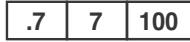
| .7 | 7 | 100 |
| MPa | bar | PSI |
| MAX FLUID WPR | ||
| MPa | bar | PSI |
| MAX TEMP 50°C (122°F) | ||
Intrinsically Safe (IS) System. Install
per IS Control Drawing No. 289833
EasyKey Interface IS Associated
Apparatus for use in non hazardous
location, with IS Connection to Smart
Fluid Plate IS
Apparatus for use in:
Class I, Division 1, Group D T3 C
Hazardous Locations
Read Instruction Manual
Warning: Substitution of components
may impair intrinsic safety.
PART NO.
SERIAL

MFG. YR.

D INC.
P.O.Box 1441
Minneapolis, MN
55440 U.S.A.
TI12421a
Étiquette de la station de fluide
ProMix® 2KS
PART NO. SERIES SERIAL MFG.YR.

Intrinsically
for Class I, Div 1, Group D, To = -20^ to 50^
Ta = 20°C to 50°C Install per 289833
Instal per 20000
3538

0359

FM08ATEX0073
MAX AIR WPR
MPa bar PSI

GRACO INC.
P.O.Box 1441
Minneapolis, MN
U.S.A.
TI13581a
Recipe & Advanced Setup
System Configuration
ST1
ST1
EK 2.00.012 BC 1.XX C1 2.01
FP 2.00.012 AK 2K-Auto C2 --
XP V6.6.0.2 MC 1042.0198
IP 10.33.131.205 MAC 00204AAD1810
Flush and Fill Input
K-Factor Input
Min Material Fill Volume


FIG. 36: Ecran d'option 1
Configure
Options
Home
Warning: Switching to Global Source
Global source recipe for Flush and Fill Input
This will overwrite recipe data. Are you sure?

Minimum Flush Volume
Potlife Time
Color/Catalyst Purge
Color/Catalyst Fill
Advanced
Recipe

FIG. 49: Écran de configuration des compositions 1
2cc

minutes

seconds

seconds


FIG. 50: Écran de configuration des compositions 2
Home
Volume de rinceage minimum
| Rapport = 2,0:1 | Dose 1 | Dose 2 | Dose 3 | |||
| A = 2 | ||||||
| B = 1 | ||||||
ProMix 2KS Recipe Change
Chart 1: A1 to A2, B1 to B2 with Dump Valves
Notes:
Purge from old recipe
Fill from new recipe
Load tables from new recipe
ProMix 2KS Recipe Change
Chart 2: A1 to A2, B1 to B2 with Dump Valves and 3rd Flush Valve
Purge from old recipe
Fill from new recipe
*Applies to ALL charts when 3rd Flush Valve is ON
Load tables from new recipe
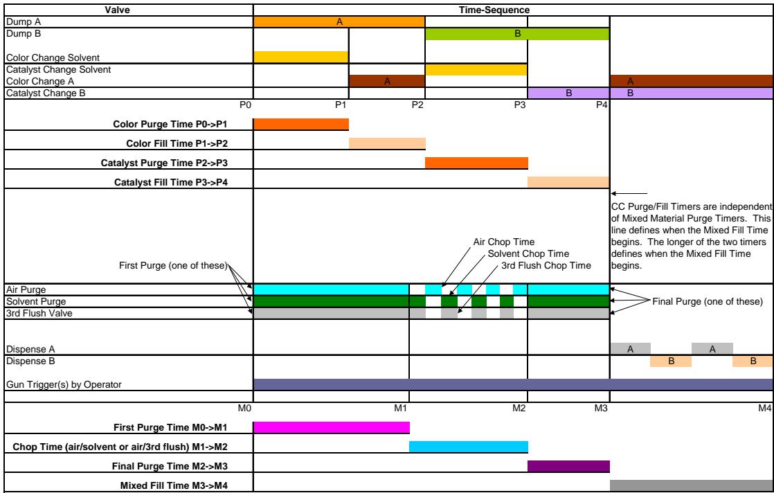
ProMix 2KS Recipe Change
Chart 3: A1 to A2, same B with Dump Valves
| Valve | Time-Sequence | |||||
| Dump A | A | |||||
| Dump B | ||||||
| Color Change Solvent | ||||||
| Catalyst Change Solvent | ||||||
| Color Change A | A | A | ||||
| Catalyst Change B | B | |||||
| P0 | P1 | P2 | P3 | P4 | ||
| Color Purge Time P0>P1 | ||||||
| Color Fill Time P1>P2 | ||||||
| First Purge (one of these) | Air Chop Time Solvent Chop Time 3rd Flush Chop Time | CC Purge/Fill Timers are independent of Mixed Material Purge Timers. This line defines when the Mixed Fill Time begins. The longer of the two timers defines when the Mixed Fill Time begins. | ||||
| Air Purge | Final Purge (one of these) | |||||
| Solvent Purge | ||||||
| 3rd Flush Valve | ||||||
| Dispense A | A | A | ||||
| Dispense B | B | B | ||||
| Gun Trigger(s) by Operator | ||||||
| M0 | M1 | M2 | M3 | M4 | ||
| First Purge Time M0>M1 | ||||||
| Chop Time (air/solvent or air/3rd flush) M1>M2 | ||||||
| Final Purge Time M2>M3 | ||||||
| Mixed Fill Time M3>M4 | ||||||
Notes:
Purge from old recipe
Fill from new recipe
Load tables from new recipe
ProMix 2KS Recipe Change
Chart 4: A1-A2, same B without Dump Valves
| Valve | Time-Sequence | ||||||
| Dump A | |||||||
| Dump B | |||||||
| Color Change Solvent | |||||||
| Catalyst Change Solvent | |||||||
| Color Change A | A | A | |||||
| Catalyst Change B | Air Chop Time | B | |||||
| First Purge (one of these) | Solvent Chop Time | ||||||
| Air Purge | 3rd Flush Chop Time | ||||||
| Solvent Purge | |||||||
| 3rd Flush Valve | |||||||
| Dispense A | A | A | B | ||||
| Dispense B | B | B | |||||
| Gun Trigger(s) by Operator | |||||||
| 0 | 1 | 2 | 3 | 4 | 5 | 6 | |
| Color Purge Time 0->1 | |||||||
| Color Fill Time 1->2 | |||||||
| First Purge Time 2->3 | |||||||
| Chop Time (air/solvent or air/3rd flush) 3->4 | |||||||
| Final Purge Time 4->5 | |||||||
| Mixed Fill Time 5->6 | |||||||
Notes:
Purge from old recipe
Fill from new recipe
Load tables from new recipe
ProMix 2KS Recipe Change
Chart 5: B1 to B2, same A with Dump Valves
| Valve | Time-Sequence | ||||
| Dump A | |||||
| Dump B | B | ||||
| Color Change Solvent | |||||
| Catalyst Change Solvent | |||||
| Color Change A | A | ||||
| Catalyst Change B | B | B | |||
| P0 | P1 | P2 | P3 | P4 | |
| Catalyst Purge Time P0>P1 | |||||
| Catalyst Fill Time P1>P2 | |||||
| First Purge (one of these) | Air Chop Time Solvent Chop Time 3rd Flush Chop Time | CC Purge/Fill Timers are independent of Mixed Material Purge Timers. This line defines when the Mixed Fill Time begins. The longer of the two timers defines when the Mixed Fill Time begins. | |||
| Air Purge | Final Purge (one of these) | ||||
| Solvent Purge | |||||
| 3rd Flush Valve | |||||
| Dispense A | A A B | ||||
| Dispense B | |||||
| Gun Trigger(s) by Operator | |||||
| M0 | M1 | M2 | M3 | M4 | |
| First Purge Time M0>M1 | |||||
| Chop Time (air/solvent or air/3rd flush) M1>M2 | |||||
| Final Purge Time M2>M3 | |||||
| Mixed Fill Time M3>M4 | |||||
Notes:
Purge from old recipe
Fill from new recipe
Load tables from new recipe
ProMix 2KS Recipe Change
Chart 6: A1 to A2, B1 to B2 with Dump Valves, 2 GFBs
| Valve | Time-Sequence | |||||
| Dump A | A | B | A | |||
| Dump B | ||||||
| Color Change Solvent | ||||||
| Catalyst Change Solvent | ||||||
| Color Change A | A | |||||
| Catalyst Change B | B | B | ||||
| P0 | P1 | P2 | P3 | P4 | ||
| Color Purge Time P0>P1 | ||||||
| Color Fill Time P1>P2 | ||||||
| Catalyst Purge Time P2>P3 | ||||||
| Catalyst Fill Time P3>P4 | ||||||
| First Purge (one of these) | Air Chop Time Solvent Chop Time 3rd Flush Chop Time | CC Purge/Fill Timers are independent of System Purge Timers. This line defines when the System Fill Time begins. The longer of the two timers defines when the System Fill Time begins. | ||||
| Air Purge | ||||||
| Solvent Purge | Final Purge (one of these) | |||||
| 3rd Flush Valve | ||||||
| Dispense A | A | A | ||||
| Dispense B | B | B | ||||
| Gun Flush Box Output #1 | ||||||
| Gun Flush Box Output #2 | ||||||
| M0 | M1 | M2 | M3 | M4 | ||
| First Purge Time M0>M1 | ||||||
| Chop Time (air/solvent or air/3rd flush) M1>M2 | ||||||
| Final Purge Time M2>M3 | ||||||
| Mixed Fill Time M3>M4 | ||||||
Notes:
Purge from old recipe
Fill from new recipe
Load tables from new recipe
ProMix 2KS Recipe Change Chart 7: A1 to A2, B1 to B2 with Dump Valves, 1 GFB
| Valve | Time-Sequence | |||||
| Dump A | A | |||||
| Dump B | B | |||||
| Color Change Solvent | ||||||
| Catalyst Change Solvent | ||||||
| Color Change A | A | A | ||||
| Catalyst Change B | B | B | ||||
| P0 | P1 | P2 | P3 | P4 | ||
| Color Purge Time P0>P1 | ||||||
| Color Fill Time P1>P2 | ||||||
| Catalyst Purge Time P2>P3 | ||||||
| Catalyst Fill Time P3>P4 | ||||||
| First Purge (one of these) | Air Chop Time Solvent Chop Time 3rd Flush Chop Time | CC Purge/Fill Timers are independent of Mixed Material Purge Timers. This line defines when the Mixed Fill Time begins. The longer of the two timers defines when the Mixed Fill Time begins. | ||||
| Air Purge | Final Purge (one of these) | |||||
| Solvent Purge | ||||||
| 3rd Flush Valve | ||||||
| Dispense A | A | B | ||||
| Dispense B | ||||||
| Gun Flush Box Output #1 | ||||||
| Gun Flush Box Output #2 | ||||||
| M0 | M1 | M2 | M3 | M4 | ||
| First Purge Time M0>M1 | ||||||
| Chop Time (air/solvent or air/3rd flush) M1>M2 | ||||||
| Final Purge Time M2>M3 | ||||||
| Mixed Fill Time M3>M4 | ||||||
Notes:
Load tables from new recipe
Purge from old recipe
Fill from new recipe
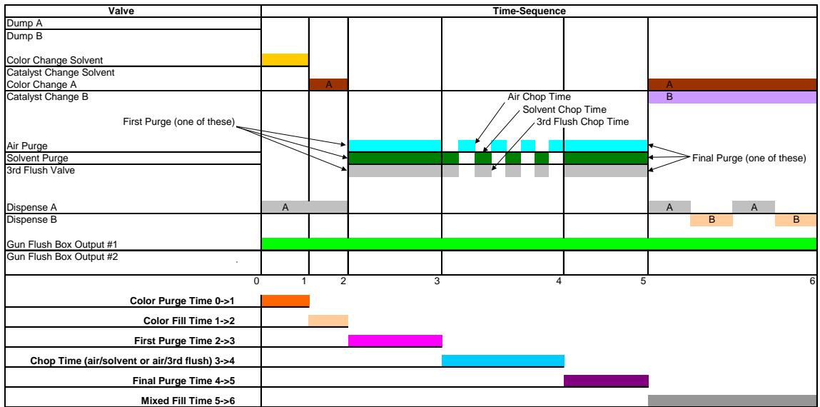
ProMix 2KS Recipe Change Chart 8: A1-A2, same B without Dump Valves, 2 GFBs
| Valve | Time-Sequence | |||||||
| Dump A | ||||||||
| Dump B | ||||||||
| Color Change Solvent | ||||||||
| Catalyst Change Solvent | ||||||||
| Color Change A | A | A | ||||||
| Catalyst Change B | Air Chop Time | B | ||||||
| First Purge (one of these) | Solvent Chop Time | |||||||
| Air Purge | 3rd Flush Chop Time | |||||||
| Solvent Purge | ||||||||
| 3rd Flush Valve | Final Purge (one of these) | |||||||
| Dispense A | A | A | A | |||||
| Dispense B | B | B | ||||||
| Gun Flush Box Output #1 | ||||||||
| Gun Flush Box Output #2 | ||||||||
| 0 | 1 | 2 | 3 | 4 | 5 | 6 | ||
| Color Purge Time 0->1 | ||||||||
| Color Fill Time 1->2 | ||||||||
| First Purge Time 2->3 | ||||||||
| Chop Time (air/solvent or air/3rd flush) 3->4 | ||||||||
| Final Purge Time 4->5 | ||||||||
| Mixed Fill Time 5->6 | ||||||||
Notes:
Load tables from new recipe
Purge from old recipe
Fill from new recipe
ProMix 2KS Recipe Change
Chart 9: A1-A2, same B without Dump Valves, 1 GFB
Notes:
Purge from old recipe
Fill from new recipe
Load tables from new recipe
ProMix 2KS Recipe Change
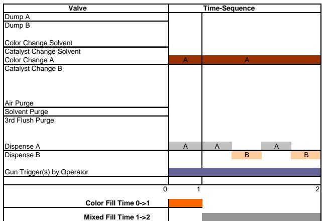
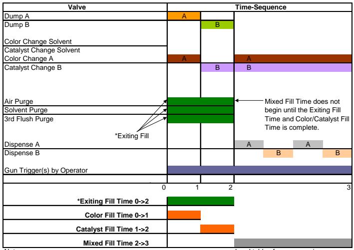
Chart 10: Recipe X, 0, OR 61 to Recipe 0 with Dump Valves
ProMix 2KS Recipe Change
Chart 11: Recipe 0 OR 61 to Recipe X with Dump Valves
| Valve | Time-Sequence | ||
| Dump A | A | ||
| Dump B | B | ||
| Color Change Solvent | |||
| Catalyst Change Solvent | |||
| Color Change A | A | A | |
| Catalyst Change B | B | B | |
| Air Purge | |||
| Solvent Purge | |||
| 3rd Flush Purge | |||
| Dispense A | A | ||
| Dispense B | B | ||
| Gun Trigger(s) by Operator | |||
| 0 | 1 | 2 | 3 |
| Color Fill Time 0->1 | |||
| Catalyst Fill Time 1->2 | |||
| Mixed Fill Time 2->3 | |||
Notes:
Purge from old recipe
Fill from new recipe
Load tables from new recipe
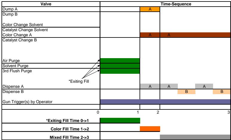
ProMix 2KS Recipe Change
Chart 12: Recipe X, 0, OR 61 to Recipe 0 without Dump Valves
| Valve | Time-Sequence | ||||
| Dump A | |||||
| Dump B | |||||
| Color Change Solvent | |||||
| Catalyst Change Solvent | |||||
| Color Change A | |||||
| Catalyst Change B | |||||
| First Purge (one of these) | |||||
| Air Purge | |||||
| Solvent Purge | |||||
| 3rd Flush Valve | |||||
| Dispense A | A | ||||
| Dispense B | |||||
| Gun Trigger(s) by Operator | |||||
| 0 | 1 | 2 | 3 | 4 | |
| Color Purge Time 0->1 | |||||
| First Purge Time 1->2 | |||||
| Chop Time (air/solvent or air/3rd flush) 2->3 | |||||
| Final Purge Time 3->4 | |||||
Notes:
All timing from Recipe 0
ProMix 2KS Recipe Change
Chart 13: Recipe 0 OR 61 to Recipe X without Dump Valves
Notes:
Purge from old recipe
Fill from new recipe
Load tables from new recipe
ProMix 2KS Recipe Change
Chart 14: A1 to A2, B1 to B2 with All
Purge from old recipe
Fill from new recipe
Load tables from new recipe
ProMix 2KS Recipe Change 16:External Color Change Option
ProMix 2KS Recipe Change
Chart 17: Recipe 0 OR 61 to Recipe X with Dump Valves and 3rd Flush Valve
Notes: Mixed Material Purge Timers from old recipe
CC Purge/Fill Timers and Mixed Fill Time from new recipe
*Exiting Fill Source and Length are Programmable
ProMix 2KS Recipe Change
Chart 18: Recipe 0 OR 61 to Recipe X without Dump Valves and 3rd Flush Valve
FIG. 106 : Diagramme de changement de couleur 18
Notes
Load tables from new recipe
Mixed Material Purge Timers from old recipe
CC Purge/Fill Timers and Mixed Fill Time from new recipe
*Exiting Fill Source and Length are Programmable
This manual contains French. MM 312779
GRACO INC. P.O. BOX 1441 MINNEAPOLIS, MN 55440-1441
Brand : GRACO
Model : PROMIX 2KS
Category : Spraying Equipment