
PRO MIX 2KS - Painting Equipment GRACO - Free user manual and instructions
Find the device manual for free PRO MIX 2KS GRACO in PDF.


| Product Type | Two-component electronic paint proportioner for professional use |
| Brand and Model | GRACO PRO MIX 2KS |
| Power Supply | 85-250 VAC, 50/60 Hz, 2 A max, 15 A max circuit breaker required |
| Maximum Fluid Working Pressure | Base system: 4000 psi (28 MPa); with Coriolis flowmeter: 2300 psi (16.1 MPa) |
| Working Air Pressure | 75-100 psi (0.5-0.7 MPa, 5.2-7 bar) |
| Mix Ratio Range | 0.1:1 to 50:1 in increments of 0.1 |
| Ratio Accuracy | Up to ±1%, user-adjustable |
| Flowmeter Flow Range | G3000: 75-3800 cc/min; G3000HR: 38-1900 cc/min; Coriolis: 20-3800 cc/min |
| Fluid Viscosity | 20-5000 cps |
| Operating Temperature | 41-122°F (5-50°C) |
| Main Functions | Sequential or dynamic metering, color change, purge, flowmeter calibration, web interface |
| Display and Control | EasyKey with LCD screen (MD model) or no screen (ME model); operator control cabinet |
| Suitable Material Types | Two-component paints: epoxy, polyurethane, acid catalyst, waterborne or solvent-based; do not use for fast-drying (< 15 min pot life) |
| Wetted Parts | 303, 304 SST, tungsten carbide (nickel binder), perfluoroelastomer, PTFE |
| Safety and Certifications | Approved for hazardous areas (Class I, Div I, Group D, T3); protective equipment required (goggles, gloves, respirator) |
| Maintenance and Cleaning | Regular purge with air and solvent; periodic flowmeter calibration; depressurization procedure before maintenance |
| Warranty | 12 months (parts and labor), except normal wear |
Frequently Asked Questions - PRO MIX 2KS GRACO
User questions about PRO MIX 2KS GRACO
0 question about this device. Answer the ones you know or ask your own.
Ask a new question about this device
Download the instructions for your Painting Equipment in PDF format for free! Find your manual PRO MIX 2KS - GRACO and take your electronic device back in hand. On this page are published all the documents necessary for the use of your device. PRO MIX 2KS by GRACO.
USER MANUAL PRO MIX 2KS GRACO
Warning: Tank Level Low Alarm
Color 1
10 Liters Alarm Level
10 Liters Current Volume
- Refill Tank Volume
- Spray 25% of Remainder
Selection
| Rapport = 2,0:1 | Dosage 1 | Dosage 2 | Dosage 3 | |||
| A = 2 | ||||||
| B = 1 | ||||||
ProMix 2KS Recipe Change
Chart 1: A1 to A2, B1 to B2 with Dump Valves
| Valve | Time-Sequence | |||||||
| Dump A | A | B | A | |||||
| Dump B | ||||||||
| Color Change Solvent | ||||||||
| Catalyst Change Solvent | ||||||||
| Color Change A | A | |||||||
| Catalyst Change B | B | B | ||||||
| P0 | P1 | P2 | P3 | P4 | ||||
| Color Purge Time P0->P1 | ||||||||
| Color Fill Time P1->P2 | ||||||||
| Catalyst Purge Time P2->P3 | ||||||||
| Catalyst Fill Time P3->P4 | ||||||||
| First Purge (one of these) | Air Chop Time Solvent Chop Time 3rd Flush Chop Time | CC Purge/Fill Timers are independent of Mixed Material Purge Timers. This line defines when the Mixed Fill Time begins. The longer of the two timers defines when the Mixed Fill Time begins. | ||||||
| Air Purge | ||||||||
| Solvent Purge | Final Purge (one of these) | |||||||
| 3rd Flush Valve | ||||||||
| Dispense A | A | B | A | B | ||||
| Dispense B | ||||||||
| Gun Trigger(s) by Operator | ||||||||
| M0 | M1 | M2 | M3 | M4 | ||||
| First Purge Time M0->M1 | ||||||||
| Chop Time (air/solvent or air/3rd flush) M1->M2 | ||||||||
| Final Purge Time M2->M3 | ||||||||
| Mixed Fill Time M3->M4 | ||||||||
Notes:
Load tables from new recipe
Purge from old recipe
Fill from new recipe
ProMix 2KS Recipe Change
Chart 2: A1 to A2, B1 to B2 with Dump Valves and 3rd Flush Valve
| Valve | Time-Sequence | |||||||
| Dump A | A | B | A | |||||
| Dump B | ||||||||
| Color Change Solvent | ||||||||
| Catalyst Change Solvent | ||||||||
| Color Change A | A | |||||||
| Catalyst Change B | B | B | ||||||
| P0 | P1 | P2 | P3 | P4 | ||||
| Color Purge Time P0->P1 | ||||||||
| Color Fill Time P1->P2 | ||||||||
| Catalyst Purge Time P2->P3 | ||||||||
| Catalyst Fill Time P3->P4 | ||||||||
| First Purge (one of these) | Air Chop Time Solvent Chop Time 3rd Flush Chop Time | CC Purge/Fill Timers are independent of Mixed Material Purge Timers. This line defines when the Mixed Fill Time begins. The longer of the two timers defines when the Mixed Fill Time begins. | ||||||
| Air Purge | Final Purge (one of these) | |||||||
| Solvent Purge | ||||||||
| 3rd Flush Valve | ||||||||
| *Two Second Solvent Purge | A | B | A | B | ||||
| Dispense A | ||||||||
| Dispense B | B | B | ||||||
| Gun Trigger(s) by Operator | ||||||||
| M0 | M1 | M2 | M3 | M4 | M5 | |||
| *Two Second Initial Purge Time M0->M1 | ||||||||
| First Purge Time M1->M2 | ||||||||
| Chop Time (air/solvent or air/3rd flush) M2->M3 | ||||||||
| Final Purge Time M3->M4 | ||||||||
| Mixed Fill Time M4->M5 | ||||||||
Notes:
Load tables from new recipe
Purge from old recipe
Fill from new recipe
*Applies to ALL charts when 3rd Flush Valve is ON
ProMix 2KS Recipe Change
Chart 3: A1 to A2, same B with Dump Valves
| Valve | Time-Sequence | |||||
| Dump A | A | |||||
| Dump B | ||||||
| Color Change Solvent | ||||||
| Catalyst Change Solvent | ||||||
| Color Change A | A | A | ||||
| Catalyst Change B | B | |||||
| P0 | P1 | P2 | P3 | P4 | ||
| Color Purge Time P0->P1 | ||||||
| Color Fill Time P1->P2 | ||||||
| First Purge (one of these) | Air Chop Time Solvent Chop Time 3rd Flush Chop Time | CC Purge/Fill Timers are independent of Mixed Material Purge Timers. This line defines when the Mixed Fill Time begins. The longer of the two timers defines when the Mixed Fill Time begins. | ||||
| Air Purge | Final Purge (one of these) | |||||
| Solvent Purge | ||||||
| 3rd Flush Valve | ||||||
| Dispense A | A | A | ||||
| Dispense B | B | B | ||||
| Gun Trigger(s) by Operator | ||||||
| M0 | M1 | M2 | M3 | M4 | ||
| First Purge Time M0->M1 | ||||||
| Chop Time (air/solvent or air/3rd flush) M1->M2 | ||||||
| Final Purge Time M2->M3 | ||||||
| Mixed Fill Time M3->M4 | ||||||
Notes:
Purge from old recipe
Fill from new recipe
Load tables from new recipe
ProMix 2KS Recipe Change
Chart 4: A1-A2, same B without Dump Valves
| Valve | Time-Sequence | ||||||
| Dump A | |||||||
| Dump B | |||||||
| Color Change Solvent | |||||||
| Catalyst Change Solvent | |||||||
| Color Change A | A | A | |||||
| Catalyst Change B | Air Chop Time | B | |||||
| First Purge (one of these) | Solvent Chop Time | ||||||
| Air Purge | 3rd Flush Chop Time | ||||||
| Solvent Purge | |||||||
| 3rd Flush Valve | |||||||
| Dispense A | A | A | B | ||||
| Dispense B | B | B | |||||
| Gun Trigger(s) by Operator | |||||||
| 0 | 1 | 2 | 3 | 4 | 5 | 6 | |
| Color Purge Time 0->1 | |||||||
| Color Fill Time 1->2 | |||||||
| First Purge Time 2->3 | |||||||
| Chop Time (air/solvent or air/3rd flush) 3->4 | |||||||
| Final Purge Time 4->5 | |||||||
| Mixed Fill Time 5->6 | |||||||
Notes:
Purge from old recipe
Fill from new recipe
Load tables from new recipe
ProMix 2KS Recipe Change
Chart 5: B1 to B2, same A with Dump Valves
| Valve | Time-Sequence | |||||
| Dump A | ||||||
| Dump B | B | |||||
| Color Change Solvent | ||||||
| Catalyst Change Solvent | ||||||
| Color Change A | A | |||||
| Catalyst Change B | B | B | ||||
| P0 | P1 | P2 | P3 | P4 | ||
| Catalyst Purge Time P0->P1 | ||||||
| Catalyst Fill Time P1->P2 | ||||||
| First Purge (one of these) | Air Chop Time Solvent Chop Time 3rd Flush Chop Time | CC Purge/Fill Timers are independent of Mixed Material Purge Timers. This line defines when the Mixed Fill Time begins. The longer of the two timers defines when the Mixed Fill Time begins. | ||||
| Air Purge | ||||||
| Solvent Purge | Final Purge (one of these) | |||||
| 3rd Flush Valve | ||||||
| Dispense A | A | A | ||||
| Dispense B | B | B | ||||
| Gun Trigger(s) by Operator | ||||||
| M0 | M1 | M2 | M3 | M4 | ||
| First Purge Time M0->M1 | ||||||
| Chop Time (air/solvent or air/3rd flush) M1->M2 | ||||||
| Final Purge Time M2->M3 | ||||||
| Mixed Fill Time M3->M4 | ||||||
Notes:
Purge from old recipe
Fill from new recipe
Load tables from new recipe
ProMix 2KS Recipe Change
Chart 6: A1 to A2, B1 to B2 with Dump Valves, 2 GFBs
| Valve | Time-Sequence | ||||
| Dump A | A | B | A | ||
| Dump B | |||||
| Color Change Solvent | |||||
| Catalyst Change Solvent | |||||
| Color Change A | A | ||||
| Catalyst Change B | B | B | |||
| P0 | P1 | P2 | P3 | P4 | |
| Color Purge Time P0->P1 | |||||
| Color Fill Time P1->P2 | |||||
| Catalyst Purge Time P2->P3 | |||||
| Catalyst Fill Time P3->P4 | |||||
| First Purge (one of these) | Air Chop Time Solvent Chop Time 3rd Flush Chop Time | CC Purge/Fill Timers are independent of System Purge Timers. This line defines when the System Fill Time begins. The longer of the two timers defines when the System Fill Time begins. | |||
| Air Purge | |||||
| Solvent Purge | |||||
| 3rd Flush Valve | |||||
| Dispense A | |||||
| Dispense B | |||||
| Gun Flush Box Output #1 | |||||
| Gun Flush Box Output #2 | |||||
| M0 | M1 | M2 | M3 | M4 | |
| First Purge Time M0->M1 | |||||
| Chop Time (air/solvent or air/3rd flush) M1->M2 | |||||
| Final Purge Time M2->M3 | |||||
| Mixed Fill Time M3->M4 | |||||
Notes:
Purge from old recipe
Fill from new recipe
Load tables from new recipe
ProMix 2KS Recipe Change
Chart 7: A1 to A2, B1 to B2 with Dump Valves, 1 GFB
| Valve | Time-Sequence | ||||
| Dump A | A | B | A | ||
| Dump B | |||||
| Color Change Solvent | |||||
| Catalyst Change Solvent | |||||
| Color Change A | A | ||||
| Catalyst Change B | B | B | |||
| P0 | P1 | P2 | P3 | P4 | |
| Color Purge Time P0->P1 | |||||
| Color Fill Time P1->P2 | |||||
| Catalyst Purge Time P2->P3 | |||||
| Catalyst Fill Time P3->P4 | |||||
| First Purge (one of these) | Air Chop Time Solvent Chop Time 3rd Flush Chop Time | CC Purge/Fill Timers are independent of Mixed Material Purge Timers. This line defines when the Mixed Fill Time begins. The longer of the two timers defines when the Mixed Fill Time begins. | |||
| Air Purge | |||||
| Solvent Purge | |||||
| 3rd Flush Valve | |||||
| Dispense A | |||||
| Dispense B | |||||
| Gun Flush Box Output #1 | |||||
| Gun Flush Box Output #2 | |||||
| M0 | M1 | M2 | M3 | M4 | |
| First Purge Time M0->M1 | |||||
| Chop Time (air/solvent or air/3rd flush) M1->M2 | |||||
| Final Purge Time M2->M3 | |||||
| Mixed Fill Time M3->M4 | |||||
Notes:
Purge from old recipe
Fill from new recipe
Load tables from new recipe
ProMix 2KS Recipe Change
Chart 8: A1-A2, same B without Dump Valves, 2 GFBs
| Valve | Time-Sequence | |||||||
| Dump A | ||||||||
| Dump B | ||||||||
| Color Change Solvent | ||||||||
| Catalyst Change Solvent | ||||||||
| Color Change A | A | A | ||||||
| Catalyst Change B | Air Chop Time | B | ||||||
| First Purge (one of these) | Solvent Chop Time | |||||||
| Air Purge | 3rd Flush Chop Time | |||||||
| Solvent Purge | ||||||||
| 3rd Flush Valve | Final Purge (one of these) | |||||||
| Dispense A | A | A | A | |||||
| Dispense B | B | B | ||||||
| Gun Flush Box Output #1 | ||||||||
| Gun Flush Box Output #2 | ||||||||
| 0 | 1 | 2 | 3 | 4 | 5 | 6 | ||
| Color Purge Time 0->1 | ||||||||
| Color Fill Time 1->2 | ||||||||
| First Purge Time 2->3 | ||||||||
| Chop Time (air/solvent or air/3rd flush) 3->4 | ||||||||
| Final Purge Time 4->5 | ||||||||
| Mixed Fill Time 5->6 | ||||||||
Notes:
Purge from old recipe
Fill from new recipe
Load tables from new recipe
ProMix 2KS Recipe Change
Chart 9: A1-A2, same B without Dump Valves, 1 GFB
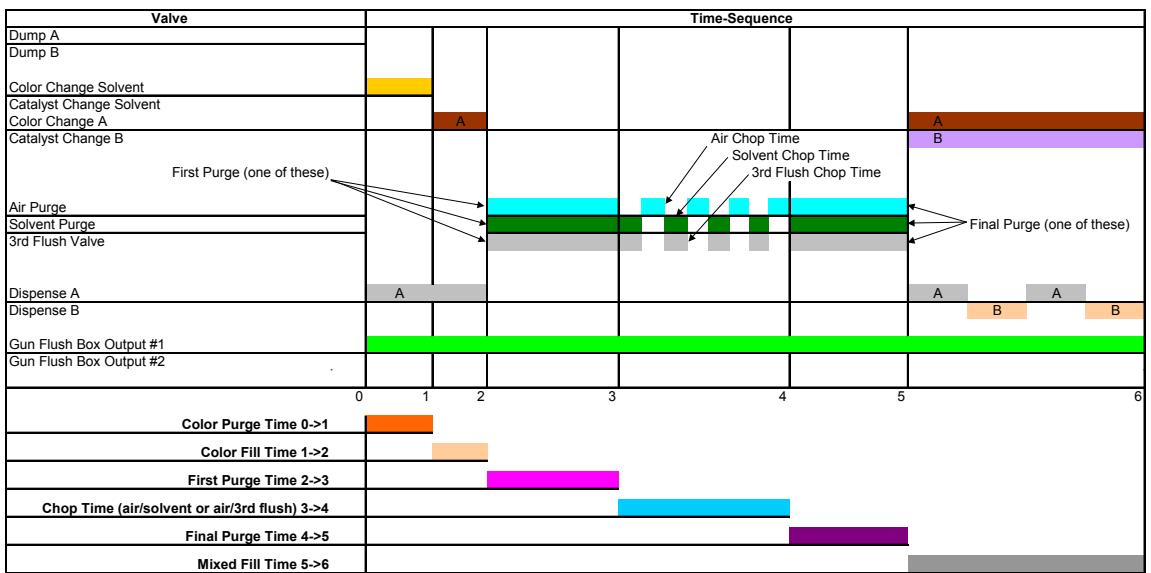
Notes:
Purge from old recipe
Fill from new recipe
Load tables from new recipe
ProMix 2KS Recipe Change
Chart 10: Recipe X, 0, OR 61 to Recipe 0 with Dump Valves
ProMix 2KS Recipe Change
Chart 11: Recipe 0 OR 61 to Recipe X with Dump Valves
| Valve | Time-Sequence | ||
| Dump A | A | ||
| Dump B | B | ||
| Color Change Solvent | |||
| Catalyst Change Solvent | |||
| Color Change A | A | A | |
| Catalyst Change B | B | B | |
| Air Purge | |||
| Solvent Purge | |||
| 3rd Flush Purge | |||
| Dispense A | A | ||
| Dispense B | B | ||
| Gun Trigger(s) by Operator | |||
| 0 | 1 | 2 | 3 |
| Color Fill Time 0->1 | |||
| Catalyst Fill Time 1->2 | |||
| Mixed Fill Time 2->3 | |||
Notes
Load tables from new recipe
Purge from old recipe
Fill from new recipe
ProMix 2KS Recipe Change
Chart 12: Recipe X, 0, OR 61 to Recipe 0 without Dump Valves
| Valve | Time-Sequence | ||||
| Dump A | |||||
| Dump B | |||||
| Color Change Solvent | |||||
| Catalyst Change Solvent | |||||
| Color Change A | |||||
| Catalyst Change B | |||||
| First Purge (one of these) | |||||
| Air Purge | |||||
| Solvent Purge | |||||
| 3rd Flush Valve | |||||
| Dispense A | A | ||||
| Dispense B | |||||
| Gun Trigger(s) by Operator | |||||
| 0 | 1 | 2 | 3 | 4 | |
| Color Purge Time 0->1 | |||||
| First Purge Time 1->2 | |||||
| Chop Time (air/solvent or air/3rd flush) 2->3 | |||||
| Final Purge Time 3->4 | |||||
Notes
All timing from Recipe 0
ProMix 2KS Recipe Change
Chart 13: Recipe 0 OR 61 to Recipe X without Dump Valves
| Valve | Time-Sequence | |||
| Dump A | ||||
| Dump B | ||||
| Color Change Solvent | ||||
| Catalyst Change Solvent | ||||
| Color Change A | A | A | ||
| Catalyst Change B | ||||
| Air Purge | ||||
| Solvent Purge | ||||
| 3rd Flush Purge | ||||
| Dispense A | A | A | A | |
| Dispense B | B | B | ||
| Gun Trigger(s) by Operator | ||||
| 0 | 1 | 2 | ||
| Color Fill Time 0->1 | ||||
| Mixed Fill Time 1->2 | ||||
Notes
Purge from old recipe
Fill from new recipe
Load tables from new recipe
ProMix 2KS Recipe Change
Chart 14: A1 to A2, B1 to B2 with All
| Valve | Time-Sequence | |||||
| Dump A | A | |||||
| Dump B | B | |||||
| Color Change Solvent | ||||||
| Catalyst Change Solvent | ||||||
| Color Change A | A | A | ||||
| Catalyst Change B | B | B | ||||
| P0 | P1 | P2 | P3 | P4 | CC Purge/Fill Timers are independent of Mixed Material Purge Timers. This line defines when the Mixed Fill Time begins. The longer of the two timers defines when the Mixed Fill Time begins. | |
| Color Purge Time P0->P1 | ||||||
| Color Fill Time P1->P2 | ||||||
| Catalyst Purge Time P2->P3 | ||||||
| Catalyst Fill Time P3->P4 | ||||||
| First Purge (one of these) | Air Chop Time Solvent Chop Time 3rd Flush Chop Time | |||||
| Air Purge | Final Purge (one of these) | |||||
| Solvent Purge | ||||||
| 3rd Flush Valve | ||||||
| Dispense A | A | A | ||||
| Dispense B | B | B | ||||
| Gun Trigger(s) by Operator | ||||||
| M0 | M1 | M2 | M3 | M4 | ||
| First Purge Time M0->M1 | ||||||
| Chop Time (air/solvent or air/3rd flush) M1->M2 | ||||||
| Final Purge Time M2->M3 | ||||||
| Mixed Fill Time M3->M4 | ||||||
| Notes: Purge from old recipe Fill from new recipe 1st On/Start | 1st On Length/Duration | 2nd On/Start | 2nd On Length | |||
| Special Output #1 | ||||||
| Special Output #2 | ||||||
| Special Output #3 | ||||||
| Special Output #4 | ||||||
| Recipe Change Purge Active Output | ||||||
| Recipe Change Fill Active Output | ||||||
ProMix 2KS Recipe Change
Chart 17: Recipe 0 OR 61 to Recipe X with Dump Valves and 3rd Flush Valve
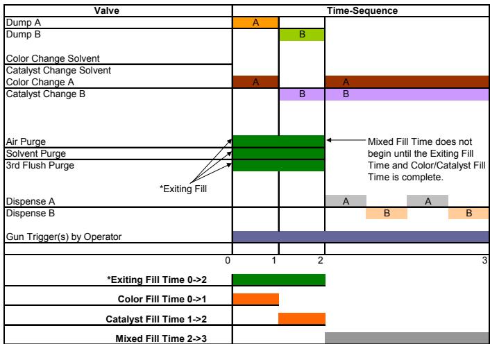
Notes:
Load tables from new recipe
Mixed Material Purge Timers from old recipe
CC Purge/Fill Timers and Mixed Fill Time from new recipe
*Exiting Fill Source and Length are Programmable
ProMix 2KS Recipe Change
Chart 18: Recipe 0 OR 61 to Recipe X without Dump Valves and 3rd Flush Valve
FIG. 86. Diagramme de changement de couleur 18
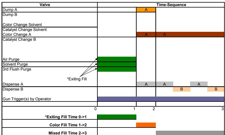
Notes:
Load tables from new recipe
Mixed Material Purge Timers from old recipe
CC Purge/Fill Timers and Mixed Fill Time from new recipe
*Exiting Fill Source and Length are Programmable
This manual contains French. MM 312776
GRACO INC. P.O. BOX 1441 MINNEAPOLIS, MN 55440-1441
Brand : GRACO
Model : PRO MIX 2KS
Category : Painting Equipment