
Z41 Pro - Touch Interface Zennio - Free user manual and instructions
Find the device manual for free Z41 Pro Zennio in PDF.


| Product Type | Multi-touch touch panel for home automation |
| Brand | Zennio |
| Model | Z41 Pro |
| Display Size | 4.3 inches |
| Resolution | 480 x 272 pixels |
| Touch Technology | Capacitive multi-touch |
| Power Supply | 24 V DC (from KNX bus or external power supply) |
| Power Consumption | Typically less than 5 W |
| Dimensions (W x H x D) | 132 x 88 x 30 mm |
| Weight | Approximately 200 g |
| Mounting | Flush mounting in standard 65 mm box |
| Environmental Protection | IP20 (indoor use only) |
| Operating Temperature | 0°C to 45°C |
| Humidity | 5% to 95% non-condensing |
| Connectivity | KNX bus (TP-256) |
| Main Functions | Control lighting, blinds, HVAC, scenes, alarms; display status and messages |
| Programming | Via ETS software (KNX tool) |
| Supported KNX Objects | Up to 200 communication objects |
| Maintenance and Cleaning | Wipe with a soft, dry cloth; avoid liquids and abrasives |
| Safety | Designed for safe operation; only qualified personnel should install and configure |
| Spare Parts and Repairability | Contact Zennio support for replacement parts; device is not user-serviceable |
| General Information | Free user manual available in PDF format; additional language translations via email request |
Frequently Asked Questions - Z41 Pro Zennio
User questions about Z41 Pro Zennio
0 question about this device. Answer the ones you know or ask your own.
Ask a new question about this device
Download the instructions for your Touch Interface in PDF format for free! Find your manual Z41 Pro - Zennio and take your electronic device back in hand. On this page are published all the documents necessary for the use of your device. Z41 Pro by Zennio.
USER MANUAL Z41 Pro Zennio



KNX Capacitive Colour Touch Panel
ZVI-Z41LIT
ZVI-Z41PRO
ZVI-Z41COM
Application Program Version Z41 Pro / Lite: [3.6]
Application Program Version Z41 COM: [1.4]
User Manual Version: [3.6]_c
www.zennio.com
CONTENTS
Contents 2
Document Updates 6
1 Introduction 9
1.1 Z41 Pro / Z41 Lite / Z41 COM 9
1.2 Functionality.... 11
1.3 Installation.... 13
1.3.1 Firmware Updates.... 15
2 Configuration....17
2.1 Menu Page 17
2.2 General-Purpose Pages 18
2.3 Configuration Page....18
2.3.1 Device....22
2.3.2 Program Configuration (Z41 Pro and Z41 Lite) 23
2.3.3 Profile 24
2.3.4 VoIP Calls (Z41 COM).... 26
2.4 Screen Orientation 28
2.5 Screensaver 29
2.5.1 Screensaver image charging.... 29
2.6 Welcome Back Object 30
2.7 Welcome Greeting 30
2.8 Backlight 30
2.9 Security....31
2.10 Page Shaping 32
2.11 Translations....33
2.11.1 Import and export translations....33
2.12 VoIP Calls (Z41 COM) 35
2.12.1 Video Intercom.... 35
2.12.1.1 Video Intercom Control 35
2.12.1.1.1 Call log....36
2.12.1.1.2 Viewing images from the camera 37
2.12.1.2 Incoming Call 38
2.12.1.3 Ongoing Call....39
2.12.2 Internal call....40
2.12.2.1 Internal call Control 40
2.12.2.2 Contacts....41
2.12.2.2.1 ETS 41
2.12.2.2.2 USB 41
2.12.2.3 Incoming Call 43
2.12.2.4 Outgoing Call 44
2.12.2.5 Ongoing Call....44
3 ETS Parameterisation 46
3.1 Default Configuration....46
3.2 Main Configuration 50
3.2.1 General 50
3.2.2 Translations....53
3.2.3 Backlight....54
3.2.4 Screensaver 56
3.2.5 Welcome Back Object 57
3.2.6 Welcome Greeting .... 58
3.2.7 Calendar 59
3.2.8 Security....60
3.2.9 Touch Lock....62
3.2.10 Internal Temperature Sensor 63
3.2.11 Ethernet (Z41 Pro and Z41 COM)....64
3.2.12 Firmware Update 65
3.2.13 VoIP Calls (Z41 COM)....66
3.2.13.1 Video Intercom....67
3.2.13.2 Internal Call 69
2.14 NTP (Z41 Pro and Z41 COM)....71
3.3 Outdoor Unit n (Z41 COM) 72
3.4 Internal Call (Z41 COM)....75
3.5 Menu 76
3.5.1 Configuration....76
3.6 Page n 78
3.6.1 Configuration....78
3.6.2 Box i....79
3.6.2.1 Indicator 81
3.6.2.1.1 Binary Indicator (Icon)....81
3.6.2.1.2 Binary Indicator (Text) 82
3.6.2.1.3 Enumerated Indicator (Icon) 82
3.6.2.1.4 Enumerated Indicator (Text) 83
3.6.2.1.5 Numerical Indicators 84
3.6.2.1.6 14-Byte Text Indicator....87
3.6.2.2 1-button Control....87
3.6.2.2.1 Binary Control 87
3.6.2.2.2 Numerical Constant Controls 88
3.6.2.2.3 Scene Control....89
3.6.2.3 2-button Control....90
3.6.2.3.1 Binary Control (Icon) 90
3.6.2.3.2 Binary Control (Text) 91
3.6.2.3.3 Enumerated Control (Icon) 92
3.6.2.3.4 Enumerated Control (Text) 93
3.6.2.3.5 Numerical Controls 94
3.6.2.3.6 Two-button Scene Control 96
3.6.2.3.7 Shutter Control....97
3.6.2.3.8 Light Dimming 98
3.6.2.4 Climate Control....99
3.6.2.4.1 Setpoint Control.... 100
3.6.2.4.2 Mode Control....103
3.6.2.4.3 Fan Control....105
3.6.2.4.4 Special Mode Control....108
3.6.2.5 Other....109
3.6.2.5.1 RGB....109
3.6.2.5.2 RGBW 112
3.6.2.5.3 Consumption Monitor....113
3.6.2.5.4 Daily Timer 116
3.6.2.5.5 Weekly Timer 118
3.6.2.5.6 Chrono-thermostat 120
3.6.2.5.7 Alarm....123
3.6.2.5.8 Holiday Calendar 125
3.6.2.5.9 Macro 128
3.6.2.5.10 Scheduler.... 130
3.6.2.5.11 Logic Function 131
3.6.2.5.12 Page Direct Link.... 133
3.6.2.5.13 Video Intercom (Z41 COM) 134
3.6.2.5.14 Internal Call (Z41 COM).... 135
3.7 Configuration Page....137
3.7.1 Configuration.... 137
3.7.2 Device....138
3.7.3 Program Configuration.... 139
3.7.4 Profile 139
3.7.5 VoIP Calls (Z41 COM).... 140
3.8 Thermostat n....142
3.9 Inputs (Z41 Pro and Z41 Lite) 143
3.9.1 Configuration.... 143
3.9.2 Binary Input....143
3.9.3 Temperature Probe 143
3.9.4 Motion Detector.... 143
3.10 Status After Programming and Bus Failure 144
ANNEX I. Remote Control via IP (Z41 Pro and Z41 COM).... 145
Configuring Z41 Pro Z41 Pro / Z41 COM 145
Pairing Procedure....146
'Push' Notifications 148
Remote Applications....149
ANNEX II. Communication Objects of Z41 Lite and Z41 Pro 150
ANNEX III. Communication Objects of Z41 COM 163
DOCUMENT UPDATES
| Version | Modifications | Page(s) |
| [3.6]_c | Changes in the document:- Change of application for remote control. | 148 |
| [3.6]_b | Changes in the application program Z41 COM:- Warning about changing My ID parameter and network settings. | - |
| [3.6]_a | Changes in the application program Z41 Pro / Z41 Lite:- Optimisation of the motion detector, binary inputs, temperature probe and thermostat modules.Changes in the application program Z41 COM:- New KNX object for opening doors- New parameter to define number of tones when receiving a call.- Optimisation of the thermostat module. | - |
| [3.5]_a | Changes in the application program:- Internal optimisation. | - |
| [3.4]_a | Changes in the application program Z41 Pro / Z41 Lite:- Support for new touch panel.- Ability to launch the welcome greeting when a text of the message is updatedChanges in the application program Z41 COM:- Incremented up to 20 the number of intercom outdoor units.- Clarification on the encoding of the internal call contacts file- Optimisation of the thermostat module. | - |
| [3.3]_a | Changes in the application program:- New icons.- Object to change the temperature scale.- New parameters to define the length of each lighting state.- Possibility to hide welcome greeting by object.- Macro, Scheduler and Logic Function: control only boxes with security level lower or equal to itself.- Heartbeat module.- Optimisation of the binary inputs, temperature probe, motion detector and thermostat modules. | - |
| [3.1]_c | Changes in the application program of Z41 COM:- Internal calls.- Heartbeat module. | - |
| [3.1]_b | Changes in the application program:- Synchronize Time/Date via NTP (Z41 Pro / Z41 COM).- Video Intercom (Z41 COM) | - |
| [3.1]_a | Changes in the application program:- Translations- Backlight brightness level- Screensaver- Welcome back object- Welcome Greeting- Update object- Security for boxes- 14-byte indicators- New controls: Macro, Scheduler, Logic Function and Page Direct Link. | - |
| [2.3]_a | Changes in General Configuration:- Screen Orientation | - |
| [2.2]_a | Changes in the application program:- Twelve general-purpose control pages.- Holiday calendar.- Water/gas monitor.- Four-byte indicators.- Error log.- Light intensity regulation on RGB / RGBW controls.- Fan speed control.- New outline of the Configuration page. | - |
1 INTRODUCTION
1.1 Z41 PRO / Z41 LITE / Z41 COM
Z41 Pro, Z41 Lite y Z41 COM are the easily and intuitively controllable high-performance colour touch screens from Zennio. The built-in features and functions make them the ideal solution for integral room control in hotels, offices or any other environments where controlling climate systems, lighting systems, shutters, scenes, etc. is required.
The main differences between Z41 Lite, Z41 Pro and Z41 COM are indicated in the following table:
| Functionality | Z41 Lite | Z41 Pro | Z41 COM |
| Analogue-digital inputs |  | [HXX5] |  |
| Ethernet Interface:- Firmware update via Ethernet.- Synchronize Time/Date via NTP.- Remote control, |  |  |  |
| Video Intercom. |  |  | [044Z] |
| Internal Calls | [6DAV] | [227K] |  |
| Battery (internal clock without power) |  |  |  |
Table 1. Differences between Z41 Lite, Z41 Pro and Z41 COM
The most outstanding features of Z41 Pro, Z41 Lite and Z41 COM are:
4.1-inch backlit capacitive touch panel, with screen resolution of 320 x 240 pixel.
- User interface with various pre-set colour patterns and themes.
Multiple direct-action functions, fully customisable.
• Control distribution across up to 12 customisable pages.
Video Intercom function compatible with GetFace IP (Only in Z41 COM).
Internal call functionality to other Z41 (Only in Z41 COM).
Full climate management.
Programmable timers.
Holiday calendar.
Scene control.
Alarm control.
Macros.
Schedulers.
Logic functions.
Direct links to other pages.
• Screensaver with custom image.
Multi-Language.
2 independent thermostats.
Built-in temperature sensor.
2 customisable analogue-digital inputs (Only in Z41 Pro and Z41 Lite).
- Ethernet interface for firmware updates and for the control of the device from remote IP applications (Only in Z41 Pro and Z41 COM).
Elegant design, available in various colours.
Celsius and Fahrenheit scales for the on-screen temperature indicators, being possible to select them in parameters or through communication object (Only in Z41 Lite and Z41 Pro).
Heartbeat or periodic "still-alive" notification.
1.2 FUNCTIONALITY
Versions 2.0 and later of the Z41 Pro / Lite / COM application program feature the following functions:
12 General-Purpose Pages, with up to 8 Fully-Customisable Boxes each, which the integrator may configure as indicators or controls.
Indicators:
○ Binary (icon or text).
- Enumerated (icon or text).
○ Unsigned integer (2 / 4 bytes)
- Signed integer (1 / 2 / 4 bytes).
- Scaling (percentage).
- Floating point (2 / 4 bytes)
○ Text (14 bytes).
1-button Controls:
- Binary (pre-set value; switch; hold & release; short press, long press...).
- Unsigned integer (1 / 2 bytes).
- Signed integer (1 / 2 bytes).
○ Scaling (percentage).
- Floating point (2 bytes).
- Scene (run / save).
2-button Controls:
- Binary (icon, text, number).
o Enumerated (icon, text). - Unsigned integer (1 / 2 bytes).
-
Signed integer (1 / 2 bytes).
○ Percentage (Scaling). -
Floating point (2 bytes).
- 2 scenes (run / save).
○ Shutters.
○ Light dimming.
▶ Climate Specific Controls:
o Temperature Setpoint control.
○ Mode (cool/heat or extended).
- Special modes.
○ Fan.
Other Controls:
○ RGB.
○ RGBW.
- Energy or Water/gas consumption.
- Daily / Weekly timer.
○ Chrono-thermostat.
○ Alarm.
- Holiday calendar.
○ Macro.
- Scheduler.
- Logic function.
- Page direct link.
- Video Intercom (Only in Z41 COM).
- Internal Calls (Only in Z41 COM).
1 Configuration Page (optional), which contains the time/date settings, the calibration of the built-in temperature probe, the alarm, error and/or call log and the contrast & brightness adjustment, among others.
Notes:
Z41 Pro / Lite / COM supports Latin, Arab, Chinese, Korean, Japanese, Greek, Cyrillic and Hebrew characters for the on-screen, customisable labels. However, only certain combinations are possible within the same parameterisation:
➢ Latin and Arab characters,
➢ Latin, Chinese, Korean and Japanese characters,
➢ Latin, Greek, Cyrillic and Hebrew characters
- Texts parameterised in ETS that may show in Z41 must comply with the UTF-8 codification format.
1.3 INSTALLATION
Figure 1 shows the connection outline of the device:
- Internal temperature probe.
- KNX connector.
- Input connectors.
(Only in Z41 Pro and Z41 Lite) - Battery.
(Only in Z41 Pro and Z41 Lite) - Prog./Test button.
- Prog./Test LED.
- Ethernet connector
(Only in Z41 Pro and Z41 COM). - Magnet.
- Mini-USB connector.
- External power supply.

Figure 1 Schematic diagram.
Z41 Pro / Lite / COM is connected to the KNX bus through the built-in terminal (2). An external DC power supply (12v / 24v / 29v) which delivers at least 150 mA of current is also required. The KNX power and the external power must be electrically isolated and provided by separate supplies, in order to avoid interference to the KNX bus. Zennio power supplies meet this requirement and can be used for Z41 Pro / Lite / COM auxiliary power supply. This external power must be supplied to the device through the corresponding terminal (10) provided within the original packaging, ensuring that each cable is properly connected and respecting the electrical polarities –positive and negative– from the supply to the device.
In addition to the external supply, Z41 Pro / Lite makes use of a button battery, located at the corresponding slot (4), to help maintain the time and date updated in case of a failure of the external power supply.
Note: immediately after connecting the external supply, the device will perform an automatic calibration, which may result deviated if it takes place while any type of pressure is being made over the front panel. In case of an unexpected behaviour in touch recognition, it will be necessary to disconnect and connect the device back, avoiding making pressure over the panel, in order to perform a new calibration.
After the connection of the external power supply, the screen will blink for an instant. A few seconds later, a welcome screen containing the Zennio logo and the "Loading..." label will be shown. Once the load process ends, the Status page will come up (see Figure 2).

Figure 2 Status Page.
This screen is divided into boxes, which contain the following information:
The "KNX" box shows the individual address assigned to the screen (in case of no assignment or no bus connection, this will show as "x.x.x").
The "Software" box will show empty in absence of an application program. In general, it will indicate if the download software is correct ("OK") or if it is found to be corrupt due to download issues ("ERROR").
The "Sync" box shows, as a percentage, the progress of the internal synchronisation of the device during the start-up. Once it reaches 100%, the Status page will disappear and the Menu page will come up.
The “Ethernet” box (only in Z41 Pro and Z41 COM) shows the IP address assigned to the device, provided that an Ethernet cable has been attached (7) and the network is running a DHCP server
- Last, the "SW Version" box shows the version of the firmware currently loaded to the device.
The Status page will also show up during bus failures in case the external power (12-24-29v) is not interrupted.
Note: although the device will not turn functional until it is powered with the external supply, the KNX bus power should be enough to perform downloads from ETS (application program, group addresses, etc.).
A short press on the Prog./Test button (5) will make the device enter the programming mode. The Prog./Test LED (6) will then light in red. On the contrary, if this button is held while the device gets connected to the bus, Z41 Pro / Lite / COM will enter the safe mode. In such case, the programming LED will blink in red colour.
Firmware updates (see section 1.3.1) can be performed through the Mini-USB (9) and Ethernet (7) connectors. It is important to take into account that USB memories must be formatted in FAT32.
For detailed information about the technical features of Z41 Pro / Lite / COM, as well as on security and installation procedures, please refer to the device Datasheet, bundled within the device packaging and also available at www.zennio.com.
1.3.1 FIRMWARE UPDATES
This device incorporates two separate microcontrollers. One of them is focused on interfacing with the KNX bus and on running the application program itself, while the second one is dedicated to running the firmware that implements the operating system and the management of the peripherals.
Therefore, updating Z41 Pro / Lite / COM may consist in two stages:
- Downloading the new application program (from ETS),
- Downloading the new firmware. There are two methods available:
Connect a flash memory USB drive to the Mini-USB port (see 9 in Figure 1), through the proper adapter cable.
In the particular case of Z41 Pro and Z41 COM, it is also possible to perform this update via Ethernet (see 7 in Figure 1).
For further details on the update process, please refer to the “Firmware update” specific document, available at www.zennio.com.
Note: firmware updates do not re-set the consumption, alarm and error logs, nor does it clear the on-screen user configuration. For further information please consult section 3.10.
Important: firmware updates via USB can be disabled in parameters (see section 3.2.12). Please bear in mind that if such possibility is left disabled and a new version of the application is downloaded before having updated the firmware to the corresponding version, then it will not be possible to re-enable it unless the application program is reverted to the version that corresponds to the current firmware version.
In other words: the device does not apply any further parameter changes in case of a version mismatch between the application program and the firmware. Therefore, it is always advisable to update the firmware (which will imply having the USB option already enabled, if necessary) prior to updating the application program.
2 CONFIGURATION
2.1 MENU PAGE
The user interface is organised into pages (up to twelve different pages, in addition to the Configuration page), each of which can be accessed from the Menu page, which (unless the contrary has been parameterised) is automatically shown after the start-up.

Figure 3 Menu Page (example).
As Figure 3 shows, the access to the pages is provided by a set of icons, which may show other (smaller) icons overlaid, such as an exclamation or a lock. Exclamations reflect that there are active alarms (see epigraph 3.6.2.5.7 in section 3.6.2.5) within the page, while a lock reflects that the access to the page is password-protected (see section 3.2.8), which also applies to the Configuration page.
All the twelve pages are general-purpose, at the entire disposal of the integrator, who may include up to 8 controls/indicators (with different functionalities) per page, being even possible to combine alarm, climate or any other controls within the same page. The remaining Configuration page is specific-purpose, as it is provided for user customisation of the device.
The user interface permanently shows a top bar (containing the name of the current page as well as the current time of day and temperature) and a button at the bottom of every page to get back to the Menu page:

Figure 4 Menu button.
2.2 GENERAL-PURPOSE PAGES
The integrator can make use of up to 12 general-purpose pages, each of which can host up to 8 different indicators or controls (with no restrictions for combining them) which will show inside the pages, automatically distributed or not, according to page parameterisation. For more details on the box distribution, refer to section 2.10.
The configurable control parameters for the general-purpose pages and their behaviour will be described in detail in section 3.
The Configuration page lets the user know or adjust certain technical values about the device, as well as customise the visual and audio adjustments of the user interface:
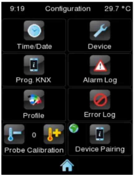
Figure 5 Configuration Page.
The specific controls that can be enabled for the Configuration page are:
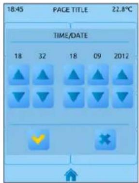
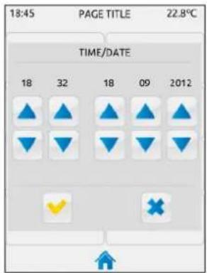
- Date/Time: even though the device implements two communication objects (see section 3.1) for setting the internal time and date from an external device, they can also be adjusted (if such option has been enabled by parameter) directly from the user interface.
Pressing this button pops up a set of controls to let the user set the current hour (0-23), minutes, day, month and year.

Figure 6 Time Set Control.
Notes:
Z41 Pro / Lite incorporate an internal clock powered by a battery (see section 1.3). Therefore, time/date is not lost after downloads or reboots.
Z41 COM has no battery, so it is recommended to enable the NTP functionality (see section 3.2.14) or to obtain the date and hour externally, through the bus.
In Z41 COM, having the date and time updated is very important, so that the data of the call log entries of the video intercom are reliable. This is particularly important when there are several Z41 COM synchronized in the installation. It is recommended that all of the Z41 obtain the date and hour from the same source.
• Device: button that provides access to a set of device-specific controls, such as the programming button or the reset button. For further details please refer to section 2.3.1.
- Program Configuration (only in Z41 Pro and Z41 Lite): button that provides access to the program information window, which shows the current version of the application program and the individual address. For further details please refer to section 2.3.2.
Note: In Z41 COM, the information of "Program Configuration" will be shown in the "Device" window.
- Alarm Log: button that provides access to the log file where alarm events are incorporated as soon as they occur. This centralised file may be useful when the user needs to check the status of a set of alarm controls distributed across several pages.
Hence, the alarm log will contain a listing, in reverse chronological order, where the name, time and date of every alarm event will be shown. In addition, the log will show the current status of each of them, which may be:
“ON”: the alarm is still active or has not been acknowledged by the user.
“OK”: the user has acknowledged the alarm event, but the corresponding object is still in the alarm state.
“OFF”: the user has acknowledged the alarm event and the corresponding object has already left the alarm state.
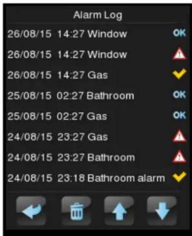
Figure 7 Alarm Log
For more information on alarms, see epigraph 3.6.2.5.7 in section 3.6.2.5.
• Profile: button that permits entering the visual and audio settings of the user interface. For further information please refer to section 2.3.3.
Error Log: button that provides access to the log file where any errors that may arise during normal operation of the device will be incorporated chronologically.

Figure 8 Error Log.
The following error types will be registered into the log:
KNX bus failure: labelled as "KNX".
External power failure: labelled as "Reboot".
Loss of LAN connectivity (Z41 Pro / COM): labelled as "Network".
Loss of WAN connectivity (Z41 Pro / COM): labelled as "Internet".
Inconsistent firmware / application program versions: labelled as "Version Mismatch". See section 1.3.1.
➢ Loss of remote control service connectivity (Zennio Remote) (Z41 Pro / COM): labelled as “Remote Control”.
The dialogue will look quite similar to the alarm log, as illustrated in the above figure. One text line with the following fields will be shown per registered error:
Date (format yyyy/mm/dd).
Time (format hh:mm:ss).
Error Type:
- KNX.
- Reboot.
-
Network.
-
Internet.
- Version Mismatch.
- Remote Control.
- Probe Calibration: control for setting a certain correction over the values thrown by the internal temperature probe. This way, if the value of the measurement is found to be slightly over (or below) the actual temperature due to external factors, the final user will have the option to set an adjustment of between -5.0°C and +5.0°C , in steps of 0.1°C . In addition, it is possible to set an initial value for such correction by parameter.
Note: any changes made to the calibration of the internal probe will be applied once the next measurement takes place. Therefore, they may not be perceived immediately.
• Device Pairing (only in Z41 Pro / Z41 COM): button for entering the device pairing function, which needs to be run prior to be controlling the device from a remote IP application. See ANNEX I. Remote Control via IP for more details about controlling Z41 remotely.
VoIP Calls Configuration (Only in Z41 COM): button for entering to video intercom and internal calls sound adjustments page, ringtone, volume and "Do Not Disturb" mode.
The labels of the controls in the Configuration page, as well as the title of the page itself, are customisable in ETS. Moreover, it is possible to make any of the described controls stay hidden for the final user. These details are explained in section 3, together with the entire parameterisation process.
2.3.1 DEVICE
The following controls may be found in the Device screen, although they can be disabled in parameters:

Figure 9 Configuration. Device. (Z41 Lite / Pro)
- Programming Button: control/indicator that shows the status of the Prog./Test LED of the device. In particular, it permits entering/leaving the programming
mode as by pressing the actual programming button of the device (see 1.3) in case the rear side of Z41 Pro / Lite / COM cannot be accessed.
- Reset: holding this button for a few seconds (i.e., a long press is required) sets the device back to a certain state, which can be set in ETS:
“Parameters Reset”: similar to restoring the device to the just-parameterised state, with the subsequent reset of the object values, alarm controls, timers, etc.
“Z41 Reboot”: simple device reset, with no data loss.
“Parameters Reset and Z41 Reboot”: the above two, combined.
Note: alarm logs, consumption logs or any other logs are not reset to zero in any case. Nevertheless, the "ETS Reset Device" option does reset any adjustment performed by the final user from the Profile and Configuration pages (excepting the time / date, which is controlled by an internal clock).
In Z41 COM, in addition, the indicators listed in the section 2.3.2 can be enabled in this page, as shows the following figure:

Figure 10 Configuration. Device. (Z41 COM)
2.3.2 PROGRAM CONFIGURATION (Z41 PRO AND Z41 LITE)
The indicators that can be enabled for the Program Configuration window are:
- KNX: indicator that reflects the current individual address of the device within the KNX installation.
Program version: indicator that shows the version of the device and, on the right, of the application program currently installed on the device. See section 1.3.1 for more details.
IP Address (only in Z41 Pro / Z41 COM): indicator showing the IP address of the device. The IP address can be static (only in Z41 COM) or dynamic, assigned for a DHCP server.
MAC Address (only in Z41 Pro / Z41 COM): indicator showing the MAC address of the device.

Figure 11 Configuration. Program Configuration.
Note: In Z41 COM these indicators can be found in the Device window (see section 2.3.1)
2.3.3 PROFILE
It is possible to enable the following controls for the Profile page:
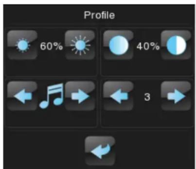

Figure 12 Configuration. Profile (Left: Z41 Lite / Z41 Pro, right: Z41 COM).
Contrast.
Brightness.
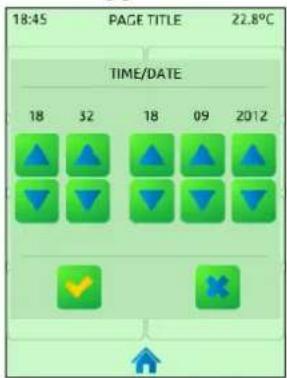
Theme: desired colour combination, among eight different options:

Ocean
Sky

Night

Twilight
Egg Shell

Seaside

Rioja
Forest
Figure 13 Themes
Melody (Z41 Lite and Pro): desired tune (among three different options) for the beeps emitted on button presses or as a feedback on action executions. One more possibility is to make these beeps silent (alarm beeps will still sound).
• Volume (Z41 COM): in Z41 COM, instead of melody, the lower left box will control the volume of the beeps. There are three volume levels, apart from the mute option.
Note that the labels of the controls in the Profile page, as well as the title of the page itself, are customisable in ETS. Moreover, it is possible to make any of the described
controls remain hidden for the final user. These details are explained in section 3, together with the entire parameterisation process.
2.3.4 VoIP CALLS (Z41 COM)
Only in Z41 COM the Video Intercom and Internal Calls function is available (see section 2.12 for details). In its configuration page there are five controls and one indicator, as shown in the following figure:
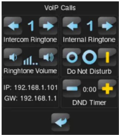
Figure 14 VoIP Calls Configuration
Video Intercom Ringtone: Desired tune reproduced when receiving a call from an outdoor unit. There are seven different ringtones. Browsing through them, the selected one will play once.
- Internal Call Ringtone: Desired tune reproduced when receiving a call from an indoor unit. There are seven different ringtones. Browsing through them, the selected one will play once.
- Ringtone Volume: Control to select the ringtone volume when receiving a call. There are five levels available and the mute option.
- “Do Not Disturb” Mode: Enabling: When enabled, incoming calls will not be received. However, in case of Video Intercom functionality, they will be registered in the call log.
When enabling the mode, the value '1' is sent through the object "[VoIP] "Do Not Disturb" Mode" and when disabling it is sent the value '0'.
Note: if "Do Not Disturb" mode is enabled during a call, the call will go on normally and the "Do Not Disturb" mode will be activated when the call finishes.
- “Do Not Disturb” Mode: Timing: Countdown to disable do not disturb mode. If set to 0 this mode will be active indefinitely.
When enabling the mode, the value '1' is sent through the object "[VoIP] "Do Not Disturb" Mode" and when the timing expires it is sent the value '0'. It is also possible to stop the countdown by manually disabling the mode (or through the communication object).
IP Address: IP address to be indicated on the outdoor video intercom unit or on another indoor unit to establish communication. It is set by parameter (see section 3.2.13).
• Gateway: Gateway of the outdoor or indoor unit, set by parameter (see section 3.2.13).
By default, all figures in this manual show a vertical arrangement of the device. However, it is also possible to set a horizontal orientation (see section 3.2.1):
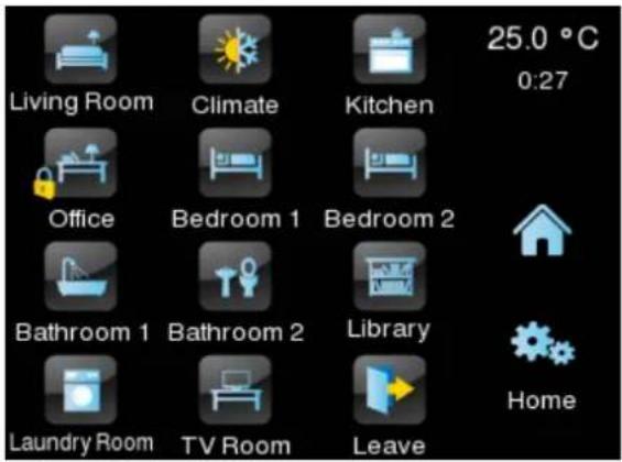
Figure 15 Horizontal orientation
In the case of a horizontal arrangement, page titles can be configured as two separate text lines, instead of as only one:

Figure 16 Page title
Therefore, the current page label (at the bottom right in Figure 15) will make better use of the available space. However, the boxes that provide access to the pages will always show a sole text line by concatenating both texts (with a blank between them) and stretching accordingly so the whole text can fit, as in the “Laundry Room” box in Figure 15.
2.5 SCREENSAVER
The screensaver is a special page that will only be shown after a period of inactivity, configurable by parameter.
It is possible to configure the screensaver to show the current Time, the current Temperature (selecting the desired measurement source: the internal temperature sensor or an external value), both or an image uploaded via USB (see section 2.5.1).
The screensaver will disappear when touching the screen (also when the illumination mode or the language changes).
Note: when showing the welcome greeting (see section 2.7), screensaver will not become active.
2.5.1 SCREENSAVER IMAGE CHARGING
To upload a screensaver image just need to be copied into an USB memory device and connect it to the USB connector of Z41. The image must fulfil the following requirements:
It has to be a JPEG image (file extension ".jpg") with 240 x 320 pixels resolution for vertical orientation or 320 x 240 pixels for horizontal orientation.
The image name must be "screensaver", without capital letters.
The product of the width by the height of the image in pixels should not exceed 2.5 megapixels.
The image size must be less than 10MB. However, depending on the device configuration and parameterisation, images with smaller sizes may not be set correctly.
The USB memories must be formatted in FAT32.
If there was already a screensaver image in Z41, the image will be overwritten.
If the image resolution is greater than the screen's, the image will be resized. To obtain an ideal visualization it is recommended to choose an image which has the same aspect ratio than the screen, depending on the parameterized orientation.
2.6 WELCOME BACK OBJECT
Z41 Pro / Lite / COM can send a specific object (the welcome back object) to the KNX bus when the user presses a touch button after a significant amount of time since the last press. Sending it or not can also depend on an additional, configurable condition consisting in the evaluation of up to five binary objects.
The welcome back object can consist in a one-bit value or a scene value (or both), depending on the parameterisation.
2.7 WELCOME GREETING
This function permits showing the user a welcome message of up to four lines of text on the display, each of which can be object-dependant or set in parameters.
When a “1” is received through the welcome greeting one-bit object, the display will become blank and show the welcome text. The same will happen if any of the 14-byte objects that define the text lines receives a new value from the bus.
2.8 BACKLIGHT
It is possible to configure brightness user-defined levels for the display of Z41 Pro / Lite / COM. Two operation modes are available: the normal mode and the night mode. The second one is optional. It is provided for temporary situations and environments where an excess of brightness may disturb the user. In such cases, it will be possible to switch the mode by means of a one-bit object and/or a scene object.
In order to prevent unnecessary power consumption while the device is idle in normal mode, the backlight of the screen is partially faded out after a few minutes without any user interaction. After that, if the inactivity persists for a few more minutes, the backlight is completely turned off. While partially or totally faded out, any press on the screen will bring back the normal light level.
The timings for the above behaviour may differ in case a pop-up window is open, as well as depending on the configuration set in parameters (see section 3.2.3 for details).
The behaviour is different during night mode. When this mode is active, brightness level established by parameter will remain constant but it is possible to define a specific
brightness level to be applied when the user interacts with the screen. In addition, a duration time for this lighting can be set, after which it will return to the level set for the night mode if no activity is detected.
2.9 SECURITY
It is possible to configure one or two different passwords, so the integrator can afterwards configure whether the access to a page or box will be protected by one password or another, or remain unprotected – every page can be independently configured. Figure 17 shows the “enter password” dialog shown to the user when trying to access a protected page.
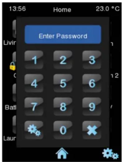
Figure 17 Password Insertion Dialog (for password-protected pages)
In case of setting up two levels, the first one is assumed to be enclosed by the second one. This means that whenever the device asks the user to type password #1 (to enter a certain page); password #2 will also be accepted. On the contrary, password #1 cannot be used instead of password #2. This behaviour permits, therefore, making password #2 available to users with further privileges while password #1 is assigned to users with fewer privileges.
Moreover, when accessing to a protected page, all the boxes and pages with the same or lower access level of the introduced password, are automatically unlocked. It can be set if the elements are relocked after a time period or a page switch.
2.10 PAGE SHAPING
Each of the pages of the user interface –including Menu and Profile– can be independently parameterised to display its control/indicator boxes statically distributed or automatically ordered.
Static (grid) Distribution: all the eight boxes of the page will be shown, remaining empty those not having been assigned a function.

Figure 18 Static Distribution
• Automatic Distribution: the active boxes will be dynamically ordered, so that they make use of all the available space. The final distribution of the page will therefore depend on the number of boxes with a function assigned.

Figure 19 Dynamic Distribution of the enabled boxes
2.11 TRANSLATIONS
Texts shown on the screen can be translated into up to five different languages. Switching from language to another can be done through two types of communication objects:
A one-byte object. The values expected by this object are fixed from 0 to 4, to select the corresponding language. When receiving the value of a non-enabled language, the main language will be activated. When the received value is out of range, the active language remains unchanged.
A two-byte ASCII object. The values expected by this object are two ASCII code characters corresponding to the ISO 639-1 standard. When receiving the value of a non-enabled language, the main language is selected.
Note: please refer to http://en.wikipedia.org/wiki/List_of_ISO_639-1_codes for a table with the language codes
The language corresponding to the texts introduced in ETS must be indicated by means of a parameter and will be the one shown by default (main language).
Translations should be uploaded to the device through an external USB memory. The desired language can be selected by means of the mentioned communication object. If the value does not correspond to any language the current language will be maintained.
2.11.1 IMPORT AND EXPORT TRANSLATIONS
The translations will be saved in “.xlf” files in the Z41. After a download, the ETS parameterized texts will be the ones in the main language (or language 0 file), and it will be overwritten.
Other languages files will have to be generated externally and, afterwards, uploaded to the Z41. For this purpose, it will be possible to export and import languages via USB. Only 1 to 4 languages can be imported and only de main language or language 0 can be exported. The next requirements must be fulfilled:
- Export: it must be created an empty folder named "lang_export" on the root directory of a pen drive and connect it to the Z41. A file named "text-dflt_0.xlf", with all the parameterised texts in ETS will be created in the mentioned folder.
- Import: it must be created another folder named "lang_import" containing the files with extension ".xlf" of the desired languages to incorporate. The files names should follow the nomenclature "text-xx_n.xlf", where "xx" must be the two letters code from the ISO-639-1 rule, and "n" the number associated to the translation. For example, "text-es_1.xlf" would be language 1 corresponding to Spanish. Once the translations are finished, plug in the USB to the Z41, and the translations will be imported automatically.
Notes:
The duration of actions to import/export translations via USB can become 1 min. During this time there should be no interruptions on the connection.
The USB memories must be formatted in FAT32.
After partial download, the .xlf file for the main language is overwritten, but not for the other languages.
- Translations files should not include the characters <' or '&'. Their escape symbols should be used instead: '& It;' and '&', respectively.
For texts translations, it is recommended to use a translation management tool such as OLT (Open Language Tool), to facilitate the translation process with '.xlf' files.
2.12 VoIP CALLS (Z41 COM)
Z41 COM is capable of receiving, over its Ethernet connection, voice and video calls from:
A Zennio outdoor unit: GetFace IP. These calls are referred in this document as video intercom calls.
A Zennio indoor unit, i.e., other Z41 COM. These calls are referred in this document as internal calls.
The following sections detail each type of call.
2.12.1 VIDEO INTERCOM
Z41 COM will be able to receive calls and show images from the camera of a Zennio video intercom outdoor unit, GetFace IP. Moreover, it is possible to open the door and a call log will be available for each video intercom configured.
Up to 20 outdoor units are available in a Z41 COM, each one controlling up to 3 doors, for a total of up to 60 doors controllable by one Z41 COM. GetFace IP is responsible for controlling the doors locks.
On the other hand, one GetFace IP can make a call to a maximum of 8 Z41 COM at a time. There is a communication object to synchronize the call logs of the Z41 COM connected to the same GetFace IP when the call is accepted or rejected by one of them.
For more information about the Zennio GetFace IP, its parameterisation and the network configuration, please refer to the user manual of this device.
The following sections detail the functions and controls available in the pop ups of Z41 COM related to the functionalities of the video intercom.
2.12.1.1 VIDEO INTERCOM CONTROL
There are two types of video intercom: community or private.
The community video intercom only has access to the call log. However, the private video intercom can access to the visualization of the images of the camera of the outdoor unit (GetFace IP) at any time, without receiving a call.
2.12.1.1.1 Call log
A box configured as a Video Intercom (see section 3.6.2.5.13) has a button to access to a Call Log.
An example of a Call Log is shown in the Figure 20. Every entry contains the first image captured by the video intercom camera, the number of the entry and the date and hour of the call reception, as well as whether the call has been attended or not. In case the image cannot be captured, a default image will be shown (see Figure 21).


Figure 20 Video Intercom. Call Log

Figure 21 Video Intercom. Call Log. Default Image
The attended calls, considering attended calls the accepted and the rejected calls and those where the door has been opened, are represented by the icon , and the not attended ones by the icon . Moreover, if there is a not attended call since the last
time the call log was accessed, the indicative icon appears on the button to access the call log, as shows the following figure.

Figure 22 Video Intercom. Not attended call.
If several Z41 COM are associated to the same GetFace IP, it is required a synchronization between them to prevent inconsistent data in the call log. This synchronization is carried out by notifying the actions performed in a Z41 COM via communication object. When another Z41 COM receives, through the mentioned object, a call has been accepted or rejected from another device, a message will be displayed for a short time (see Figure 23). These messages can be changed by parameter (see section 3.2.2)


Figure 23 Video Intercom. Synchronisation messages
2.12.1.1.2 Viewing images from the camera
When a Video Intercom is parameterised as private, another button is available to access to the camera visualization page. In this page it is possible to open the doors. (see Figure 24).
Note: if the external unit is in the same network (and therefore its IP is not specified in the Z41 COM settings), the preview of the camera image will not be accessible until at least one incoming call has been received.

Figure 24 Video Intercom. Camera Visualization Page.
2.12.1.2 INCOMING CALL
The interface of the Z41 during an incoming call is as shown in the Figure 25.
It comprises: the camera images visualization, the buttons for accept or reject the call, the buttons to open the doors, the button to silence the call and the exit button.


Figure 25 Video Intercom. Incoming Call
During an incoming call, the functions available are:
- Reject Call: the call dialog is closed and the synchronisation object is sent to the bus to notify others Z41 COM linked to the same GetFace IP. The call is registered as attended. The GetFace IP does not manifest the call rejected, so the call continues from the point of view of the visitor.
- Accept Call: opens the ongoing call dialog (see section 2.12.1.3 for details) and the synchronisation object is sent to the bus to notify others Z41 COM linked to the same GetFace IP. The call is registered as attended
- Open Door: sends the command to open the door through a communication object or/and through a HTTP command (it is possible to enable secure opening with username and password), as parameterised. Besides the synchronisation object is sent to the bus to notify others Z41 COM linked to the same GetFace IP. The call will continue but is saved in the log as attended. Up to three buttons can be enabled to open up to three doors.
Notes: it is possible to configure automatic door opening when receiving a call (see section 3.3)
Exit: the incoming call dialog is closed but no notification is sent to the bus, so the call will continue in the others Z41 COM.
Mute Call: mutes the call ringtone and the synchronisation object is sent to the bus to mute the others Z41 COM linked to the same GetFace IP.
2.12.1.3 ONGOING CALL
When accepting the call, the ongoing call dialog poops up, as shown in Figure 26:
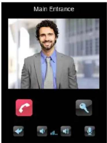

Figure 26 Video Intercom. Established Call
During an ongoing call, i.e. a call accepted the voice communication with the GetFace IP starts. The functions available are:
Reject Call: ends the communication and closes the ongoing call dialog.
- Open Door: sends the command to open the door through a communication object or/and through a HTTP command (it is possible to enable secure opening with username and password), as parameterised.
Notes: it is possible to configure automatic door opening when receiving a call (see section 3.3).
Speakers Volume: up to 5 levels of volume available plus level 0 or mute. The selected value is saved to apply in future calls.
Mute Microphone: toggles between mute and enable the microphone.
Exit: equivalent to reject call button.
2.12.2 INTERNAL CALL
Z41 COM can, via its Ethernet connection, make and receive calls from other Z41 COM.
For two screens to communicate with each other, each must have the other configured as the contact.
The following sections detail the functions and controls of the dialogs that appear in Z41 COM related to the internal calls functionalities.
2.12.2.1 INTERNAL CALL CONTROL
The interface of a box configured as internal call can be of two types: contact list or numeric keypad.
- Contact list: the screen to be contacted will be searched and selected using arrows. This option is best suited for a low number of contacts.

Figure 27 Internal Call. Contact list
- Numeric keypad: it is necessary to enter the numeric code associated with the contact to make the call. This option is best suited for a high number of contacts.

Figure 28 Internal Call. Numeric keypad.
2.12.2.2 CONTACTS
There are two ways to configure the Z41 COM contact list: via ETS or by importing contact information via USB.
The following sections explain each of these ways.
2.12.2.2.1 ETS
Up to 7 contacts can be configured in ETS. For more information, see section 3.4.
2.12.2.2.2 USB
It is possible to define the contact list in a “contacts.json” file for later import. The “contacts.json” file should contain the following information:
{
    "type": "internal_call_contacts_cfg",
    "version": 1,
    "contacts": [
    {
    "code": "001",
    "displayName": "David Adams",
    "sipId": "MY_ID_1",
    "ipAddress": "192.168.1.100",
    "differentNetwork": false
    },
    {
"code": "002",
"displayName": "Alice Jackson",
"sipId": "MY_ID_2",
"ipAddress": "192.168.1.101",
"differentNetwork": false
}
Figure 29 Two contacts example "contacts.json" file format.
The fields that must be modified for each contact are:
- “code”: numeric code associated with the contact. This field is used to call the contact using the numeric keypad.
Note: if two contacts have the same numeric code, the first contact in the imported file will be called.
- “displayName”: name that will appear in contact list and call dialogs.
- “sipId”: identifier required to carry out the communication. The corresponding screen must have this id configured in “My ID” field (see section 3.2.13.2).
Note: This field must not contain spaces or characters: >, <, ·, [, ], ( , ), &, %, ;.
- “ipAddress”: IP address of the contact. The corresponding screen must have this IP Address configured in “IP Address” field (see section 3.2.13).
• “bDifferentNetwork”: indicates whether or the contact is on different network.
To import the contact list into Z41 COM, save the contacts.json file in the root directory of an USB memory, connect it to the Z41 and restart (press the reset button or perform a bus and/or external power failure).
Important:
It is highly recommended to edit the json file with Notepad++ or a similar tool.
File encoding must be UTF-8 without BOM.
The USB memories must be formatted in FAT32.
The file name must be exactly contacts.json.
There should be no other contacts.json file in the USB memory, not even in another folder.
2.12.2.3 INCOMING CALL
The interface of the Z41 during an incoming call is shown in the Figure 30. It comprises the contact name, the buttons to accept, reject and silence the call and the exit button.

Figure 30 Incoming Internal Call
During an incoming call, the functions available are:
Reject Call: ends the call and closes the dialog. Also, for a period of time, the Z41 COM that made the internal call will display the message shown in Figure 31. This message can be changed by parameter (see section 3.2.13.2).

Figure 31 "Call Rejected" message
- Accept Call: opens the ongoing call dialog (see section 2.12.2.5 for details).
Exit: closes the incoming call dialog and the default page is displayed again. The call is not rejected, so the other Z41 COM does not get any response.
Mute: the playback of the ringtone is muted.
Note: There is no maximum incoming call time so the display will remain in this state until one of the above events mentioned is performed.
2.12.2.4 OUTGOING CALL
The interface of the Z41 during an outgoing call is shown in the Figure 32. It comprises the contact name and the buttons to reject and exit the call.
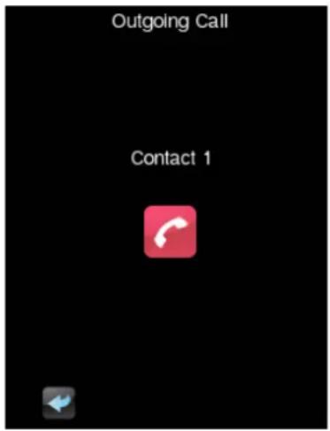
Figure 32 Outgoing Internal Call
During an incoming call, the functions available are:
- Reject Call / Exit: ends the call and closes the dialog, returning to the default page.
When the call is accepted, the ongoing call dialog will be shown and voice communication between the Z41 COM will begin:

Figure 33 Ongoing Internal Call
The functions available in this dialog are:
Reject Call: ends the communication and closes the ongoing call dialog.
Speakers Volume: up to 5 levels of volume available plus level 0 or mute. The selected value is saved to apply in future calls.
Mute Microphone: toggles between mute and enable the microphone.
Exit: equivalent to reject call button.
3 ETS PARAMETERISATION
To begin with the parameterisation of the device, once the ETS program is running it is necessary to import the product database (Z41 Pro, Z41 Lite or Z41 COM application programs). Next, the device is added to the project. The configuration process begins by entering the Parameters tab of the device.
The next sections explain the ETS parameterisation of the device in depth.
Note: the amount of characters permitted for text parameters (labels, etc.) by ETS may differ depending on whether they contain special characters (symbols, accents...) coded with more than one byte. It is advisable to verify that these texts fit properly on the screen, with independence of whether they reach the maximum text length allowed by ETS or not.
Important: whenever the device is updated to a new version of the application program from ETS, it is also necessary to update the firmware of the secondary microcontroller (responsible for the operating system; see section 1.3.1) in case an updated version exists. If the installed versions of the application program and the firmware do not match, the device may not work correctly (the Software box in the Status page will show the word "Error").
3.1 DEFAULT CONFIGURATION
This section illustrates the default initial state of the device.
| 1 | [General] Time | Current Time | 3 bytes | C | R | W | T | U | time of day |
| 2 | [General] Date | Current Date | 3 bytes | C | R | W | T | U | date |
| 3 | [General] Scenes: Send | Scene Value | 1 byte | C | - | - | T | - | scene control |
| 4 | [General] Scenes: Receive | Scene Value | 1 byte | C | - | W | - | - | scene number |
| 5 | [General] Internal Temperature | Current Temperature (Built-in Sensor) | 2 bytes | C | R | - | T | - | temperature (℃) |
| 7 | [General] Select Language | 0 = Main; 1 = Lang. 2; ... ; 4 = Lang. 5 | 1 byte | C | - | W | - | - | |
| 8 | [General] Select Language | Language selection through ISO 639-1 two letters code | 2 bytes | C | - | W | - | - | language code (ASCII) |
| 9 | [General] Illumination | 0=No Action; 1=Light Display | 1 bit | C | - | W | - | - | acknowledge |
| 11 | [General] Touch Lock | 0=Unlocked; 1=Locked | 1 bit | C | - | W | - | - | enable |
| 23 | [General] Temperature Scale | 0 = ℃; 1 = ℉F | 1 bit | C | - | W | T | U | switch |
| 24 | [Profile] Brightness | 0-100% | 1 byte | C | - | W | T | - | percentage (0..100%) |
| 25 | [Profile] Contrast | 0-100% | 1 byte | C | - | W | T | - | percentage (0..100%) |
| 26 | [Profile] Melody | 0=Mute; 1=Melody 1; 2=Melody 2; 3=Melody 3 | 1 byte | C | - | W | T | - | |
| 27 | [Profile] Theme | 0=Ocean; 1=Sky; 2=Night; 3=Twilight; 4=Egg Shell; 5=... | 1 byte | C | - | W T |
Figure 34 Default Configuration.
The general objects enabled by default are:
[General] Time: 3-byte object for setting the internal time of the device, for example, by linking it to a KNX clock. This object also allows read requests, so the current time of the device can be checked. It is also automatically sent after time changes made by the user from the screen itself.
Note: although the DPT of this object considers a field for setting the day of the week, Z41 Pro / Lite / COM calculates it from the date and therefore ignores that field.
[General] Date: 3-byte object for setting the internal date of the device, for example, by linking it to a KNX clock. This object also allows read requests, so the current date of the device can be checked. It is also automatically sent after date changes made by the user from the screen itself.
[General] Scene: Receive and [General] Scene: Send: objects for respectively receiving and sending scene values from/to the KNX bus whenever it is necessary (e.g., when the user touches a button that has been configured to send scene commands; see section 3.6.2.2).
[General] Internal Temperature: 2-byte object through which the value of the current measurement of the built-in sensor will be sent to the bus, according to the parameterisation (see section 3.2.10).
• [General] Select Language: 1 and 2-byte objects for changing the language showed in the screen when receiving a value through the bus (see section 3.2.2)
[General] Illumination: 1-bit object that, after the reception of the value "1" from the bus, will bring the backlight of the screen to the maximum level, while the reception of the value "0" will have no effect. This maximum illumination will last for a certain time, according to the explanation in section 2.8.
[General] Touch Lock: 1-bit object that, after the reception of the value "1" from the bus, will lock the touch panel so that user presses are ignored from that moment. Touch locking will be interrupted as soon as the value "0" is received through this object. See section 3.2.9.
• [General] Temperature Scale: 1-bit object which permits changing in runtime the scale of the temperatures that may show on the screen (see section 3.2.1).
• [Profile] Brightness: 1-byte object for changing the screen brightness level when receiving a value through the bus (1-100%).
• [Profile] Contrast: 1-byte object for changing the screen contrast level when receiving a value through the bus (1-100%).
• [Profile] Melody: 1-byte object for changing the melody when receiving a value through the bus (0-2 for selecting the melody and 3 for muting).
• [Profile] Theme: 1-byte object for changing the theme when receiving a value through the bus (0-7).
In addition, in Z41 COM, some video intercom objects are shown by default, which are explained in section 3.2.13.1.
During the parameter configuration, a screen similar to Figure 35 will be shown.

Figure 35 Parameter Screen shown by default
As shown in Figure 35, the parameter window is initially divided into several main tabs:
• Main Configuration, which contains a few more tabs:
▶ General,
▶ Translations,
Backlight,
▶ Calendar,
▶ Security,
▶ Touch Lock,
▶ Internal Temperature Sensor,
➢ Ethernet (Z41 Pro and Z41 COM),
➢ Firmware Update,
▶ VoIP Calls (only in Z41 COM).
Menu, which contains one more screen by default:
Configuration, from which it is possible to activate and configure each of the general-purpose pages of the device (see section 2.2).
Configuration Page, which itself will contain the following tabs:
Configuration, from which it will be possible to activate and configure the Configuration page (see section 2.3).
➢ Device, which allows enabling and configuring the controls of the Device screen (see section 2.3.1).
➢ Profile, which allows enabling and configuring the controls of the Profile screen (see section 2.3.3).
The following sections will detail the parameterisation process of each of the above tabs, including the initially hidden screens, which will become visible depending on the selected options.
3.2 MAIN CONFIGURATION
This tab is divided into multiple screens, all of which contain a set of global parameters regarding the general functionality of the device, and therefore not specifically related to a particular page of the user interface.
3.2.1 GENERAL
The General screen contains the following parameters:

Figure 36 General (Main Configuration).
Power Supply Voltage: lets the integrator specify the particular voltage of the external supply powering Z41 Pro / Lite / COM. The available values are "12" (by default), "24" and "29" volts. Selecting one option or another will only cause an internal correction over the temperature value measured by the built-in probe.
Screen Orientation: sets the desired on-screen orientation: "Vertical" or "Horizontal" (see section 2.4).
Default Theme (after programming): permits selecting the user interface colour scheme (out of 8 different options) to be loaded after the ETS download. The final user will have the option to switch the scheme from the Profile window of the Configuration page (see section 2.3.3), unless such option is disabled by parameter.
• Show Time: sets whether the current time (according to the internal clock) should show in the upper left corner of every page. The default is "Yes".
• Show Temperature: sets whether the current temperature should show or not in the upper right corner of every page, being necessary in such case to choose the source of the temperature value: "Internal temperature probe" or "External value". If the latter is chosen, an object named [General] External temperature will be enabled, so that it can be grouped with any other object that sends temperature values.
Object to change the temperature scale (only in Z41 Lite and Z41 Pro): enables or disables the 1-bit object “[General] Temperature scale”, which permits changing the scale of the temperatures. By receiving one ‘0’ through this object, the scale will switch to Celsius, while after receiving one ‘1’ it will switch to Fahrenheit.
The selected scale applies to any temperatures shown on the screen, such as:
• The screensaver temperature.
- Indicators of temperature controls linked to a box in the display.
• Temperature indicators.
In this functionality, the following parameter will also appear:
Scale after programming: sets the scale (Celsius (°C) or Fahrenheit (°F)) in use after download.
- Screensaver: enables or disables the "Screensaver" tab in the tree on the left. See section 3.2.4 for details.
- Welcome back object: enables or disables the "Welcome back" tab in the tree on the left. See section 3.2.5 for details.
- Welcome greeting: enables or disables the "Welcome greeting" tab in the tree on the left. See section 3.2.6 for details.
- Update Objects: enables the sending of read requests to update status objects and indicators. There are four options available, some of them with a configurable delay:
“Disabled”: no read request, therefore objects are not updated.
"After Programming": read requests are sent after a complete or partial download (or when pressing the reset button in the configuration page, if set as "Parameters Reset", see section 3.7.2).
"After Reset": read request are sent when a reset occurs (bus failure or the Reset Device ETS option), after the parameterised delay (0-65535 s).
“After Programming and Reset”: combination of the two above options.
- Synchronize Time/Date via NTP (only in Z41 Pro and Z41 COM): when enabled, the device will update the time and date obtained from the parameterised NTP server and time zone. This functionality is only available in Z41 Pro and Z41 COM. See section 3.2.14.
Time/Date Sending Period: when enabled (value different from zero), whenever the device is restarted, the date and time objects ("[General] Date and "[General] Time") will be sent to the bus, and thereafter, they will be sent again every time the period expires. Setting a new time to the device either through object or from the date/time configuration window will not restart the count of the sending period. Range: [0-65535] x 1 min. The default value is 10 min.
Note: to prevent time lags, it is advisable to only have one master clock within the installation. Having multiple devices overwriting each other their time and date registers periodically may end up inducing delays.
- Thermostat n: checkbox (unselected by default) that activates/deactivates the Thermostat n parameter screen. See section 3.8.
- Inputs (only in Z41 Lite and Z41 Pro): checkbox (disabled by default) to show/hide the additional Inputs screen. See section 3.9.
- Heartbeat: checkbox (disabled by default) to incorporate a one-bit object to the project ("[Heartbeat] Object to Send '1'") that will be sent periodically with value "1" to notify that the device is still working (still alive).

Figura 37 Heartbeat
Note: the first sending after download or bus failure takes place with a delay of up to 255 seconds, to prevent bus overload. The following sendings march the period set.
3.2.2 TRANSLATIONS
This screen entails certain aspects in relation to the texts languages shown on the display.

Figure 38 Translations (Main Configuration)
- Main language: read-only parameter to make it evident that the main language is always enabled.
Select language: list of the available languages.
Language X: enables or disables the additional language X.
Select language: list of available languages to select the language X.
- Label for "X": sets certain labels showed in boxes of type macro, scheduler, logic functions, video intercom or internal call (see section 3.6.2.5).
Only the Main language is enabled by default.
While Translations stays enabled, the following objects are visible:
• “[General] Select language” (one-byte).
• “[General] Select language” (two-byte).
These objects work accordingly to the behaviour mentioned in section 2.11.
After download, the main language is loaded.
3.2.3 BACKLIGHT
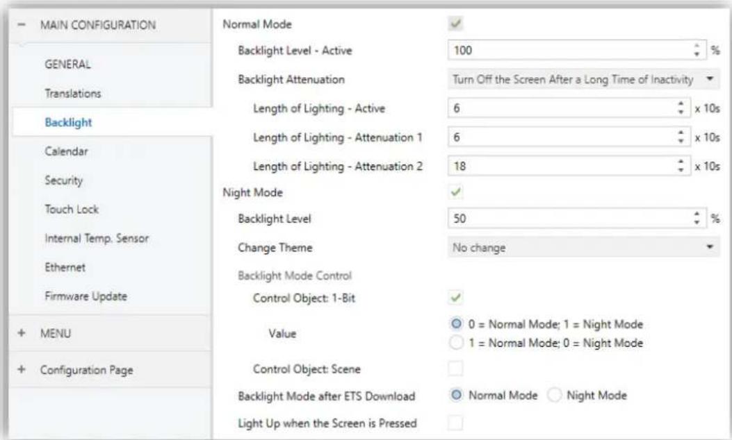
Figure 39 Backlight (Main Configuration)
This screen entails certain aspects in relation to the backlight of the display.
Normal Mode: enabled by default.
Backlight Level: display brightness percentage (0-100%).
Backlight Attenuation: lets defining whether the backlight should behave during inactivity according to section 2.8 ("Turn Off the Screen after a Long Time of Inactivity"), or if on the contrary the screen should never turn off entirely ("Attenuate the Screen after a Long Time of Inactivity") or not even attenuate the light level ("Max illumination always").
When selecting "Turn Off the Screen after a Long Time of Inactivity" or "Attenuate the Screen after a Long Time of Inactivity", the following parameters appear:
- Length of Lighting - Active, Attenuation 1, Attenuation 2: allow define how long the display remain in each lighting level.
Notes:
- "Backlight Attenuation" parameter is not available when the screensaver is enabling. However, it is possible to configure an attenuation when the screensaver activates (see section 3.2.4)
- Maintaining the default option is encouraged. Permanent illumination may affect adversely the device lifetime, and is only intended for special circumstances.
Night Mode: in case of being this mode necessary, this checkbox needs to be marked, which will incorporate some new parameters:
Backlight Level: display brightness percentage (0-100%).
Change Theme: lets select the theme when night mode is active. Options: "No change" or any of the available themes (see section 2.3.3).
In case of enabling the night mode, some more options can be configured to carry out the backlight mode control:
- Control Object: 1-Bit: when marked, it will be possible to switch the mode by writing to a binary object ("[General] Illumination"). It is possible to select which value should trigger which mode ("0 = Normal Mode; 1 = Night Mode" or "0 = Night Mode; 1 = Normal Mode").
- Control object: Scene: when marked, it will be possible to switch the mode by writing a certain scene value to “[General] Scene: Receive”. Two specific textboxes will show up to enter what scenes (1 through 64) will trigger each mode.
Backlight Mode after ETS download: sets which of the two modes ("Normal Mode" or "Night Mode") will be active after an ETS Download.
Light Up when the Screen is Pressed: allows changing temporarily the brightness level when the screen is touched in night mode.
Backlight Level after Touch: display brightness percentage (0-100%).
➢ Lenght of Lighting: when the time set in this parameter elapses, Z41 Lite / Pro / COM will switch to Night Mode (provided that it was not already in this mode). The range is 1 to 65535 seconds (10 by default).
3.2.4 SCREENSAVER
After enabling “Screensaver” from “General” screen (see section 3.2.1), a new tab will be incorporated into the tree on the left.

Figure 40 Screensaver (Main Configuration)
This screen contains the following parameters:
- Activation timeout: time to automatically show the screensaver after the last button touch. Range: 1 – 255 seconds, minutes or hours.
Attenuate Display: sets whether to decrease the display brightness when showing the screensaver.
Time/Date: sets whether to show the current time or not.
• Temperature: sets whether to show the current temperature or not. When enabled, the following parameter will show up:
Taken from: defines the source of the temperature value: "Internal sensor" or "External reference". The latter will bring a new two-byte object to the
project topology ("[General] External Temperature") so that through it the device can receive the values from the bus.
Image: sets whether to show the screensaver image (see section 2.5).
Note: The Screensaver will not appear if the Welcome Greeting is shown.
3.2.5 WELCOME BACK OBJECT
After enabling "Welcome Back Object" (see section 3.2.1), a new tab will be incorporated into the tree on the left.
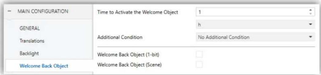
Figure 41 Welcome Back Object (Main Configuration)
Time to Active the Welcome Object: sets the minimum time (1 to 255 seconds, 1 to 255 minutes, or 1 to 255 hours) that should elapse after the last button touch before the next one trigger the execution of the welcome back function.
• Additional Condition: sets if sending the welcome back object should also depend on an external condition. The option by default is "No Additional Condition". The following are available too:
Do not send unless all additional conditions are 0: the welcome back object will only be sent if all the condition objects are found to have the value "0".
Do not send unless all additional conditions are 1: the welcome back object will only be sent if all the condition objects are found to have the value "1".
Do not send unless at least one of the additional conditions is 0: the welcome back object will only be sent if at least one of the condition objects is found to have the value "0".
Do not send unless at least one of the additional conditions is 1: the welcome back object will only be sent if at least one of the condition objects is found to have the value "1".
- Welcome Back Object (1 Bit): checkbox to enable the sending of a 1-bit value (through “[General] Welcome back”) when the welcome back function is triggered and the condition (if any) evaluates to true. The desired value (0 or 1) should be set in “Value”.
- Welcome Back Object (Scene): checkbox to enable the sending of a scene run request (through “[General] Scene: send”) when the welcome back function is triggered and the condition (if any) evaluates to true. The desired scene number (1 through 64) should be entered in “Scene Number”.
3.2.6 WELCOME GREETING
After enabling “Welcome Greeting” (see section 3.2.1), a new tab will be incorporated into the tab tree. A one-bit object named “[General] Welcome Greeting” will also be shown in the project topology, which triggers the welcome message when receives the value “1”. The message disappears when touching the screen or when receiving value “0” through the object.

Figure 42 Welcome Greeting (Main Configuration)
This screen contains the following parameters:
Line X: sets whether the corresponding text line will be pre-defined ("Fixed") or object-dependent ("Received form text object").
If "Fixed" is selected, the following parameter will appear:
Text: textbox to enter the desired text for the corresponding line.
The 14-byte object “[General] Welcome Greeting – Line X” will be shown up to four times, depending on how many text lines have been assigned the option “Received from text object”.
- Run Welcome Greeting with Text Object Update: if enabled, the welcome greeting will be launched when one of the objects “[General] Welcome Greeting – Line X” is updated.
With a parameterisation as the one shown in Figure 42, if "Mr. Marshall" is received through the "[General] Welcome Greeting – Line 2" object, the display will show the following message:

Figure 43 Welcome greeting message example.
3.2.7 CALENDAR
This screen entails certain aspects in relation to the following controls: Calendar, Daily Timer, Weekly Timer and Chrono-Thermostat (see section 3.6.2.5).
| - MAIN CONFIGURATION | First Weekday | ○ Monday ○ Sunday |
| GENERAL Translations Backlight | Default Labels (Main Language) Weekdays Initials [e.g. MTWTFSS] January Label | MTWTFSS JANUARY |
| Calendar Security Touch Lock Internal Temp. Sensor Ethernet Firmware Update | February Label March Label April Label May Label June Label July Label August Label September Label October Label November Label December Label | FEBRUARY MARCH APRIL MAY JUNE JULY AUGUST SEPTEMBER OCTOBER NOVEMBER DECEMBER |
| + MENU + Configuration Page |
Figure 44 Calendar (Main Configuration)
The parameters involved are:
- First Weekday: sets the first weekday in the calendar. The options are "Sunday" and "Monday" (default option).
- Weekdays Initials (Mon... Sun): permits customising the label that will represent each of the weekdays on the screen. A seven-character string (including letters or numbers), ordered according to the above First Weekday parameter, must be entered – each of the characters will represent one weekday. The default value is “MTWTFSS”, which stands for the day names in English.
- Label for "X": sets the label that will represent the twelve months of the year. They default values are the English names.
3.2.8 SECURITY
This screen permits selecting how many security levels (one or two) will be available for the configuration of the access to the control pages or the boxes.

Figure 45 Security: Two Security Levels
The parameters on the Security screen are:
• Security Levels: dropdown list for selecting whether one (default option) or two security levels will be available. Depending on the selection, the parameter below (Password) may show once or twice.
Note: with independence of the option selected here, it will be necessary to establish the security level desired for each specific page of controls.
- Protect again: sets when is re-activated the security of pages or boxes unlocked. The options are: "After a Time Period", "After a Page Switch" or "After a Time Period or a Page Switch" (by default). When selecting the first or the last option, a new parameter Time appears to set the time period (from 10 to 655350 seconds).
- Password: parameter made of four additional textboxes, each of which should contain one of the four consecutive digits (0-9) that will compose the password. The default password is "1234".
In case of enabling two security levels, the Password parameter will show twice, being the first one referred to the password of Level 1, and the second one to the password of Level 2. The default password for Level 2 is "5678".
Important: the password insertion dialog features a specific option (lower left button) that lets the user change, in runtime, the passwords originally set by parameter. After accessing this option and prior to typing the new password, the user will be required to type the corresponding old password (level 1 or level 2). Note that although it will be possible to type password 2 even if the device asks for password 1, the new password typed afterwards will be anyway stored as the new password for level 1.
• Security Pad Labels: parameter consisting in six additional textboxes, intended for the customisation of the messages that the device shows (or may show) when the user interacts with the password insertion dialog. Up to 15 characters are permitted per label.
Label for "Password 1": message shown when the user is required to type in the password for level 1. By default, "Password 1".
Label for "Password 2": message shown when the user is required to type in the password for level 2. By default, "Password 2".
Label for "Error": message shown to the user when the typed password is not valid. By default, "ERROR".
Label for "New password": message shown to ask the user for a new password, during the password change process. By default, "New password".
Label for "Repeat password": message shown when the user is required to re-type the new password. By default, "Repeat password".
Label for "Updated": message shown to the user as a confirmation of the password change. By default, "Updated".
Buttons that lead to a protected page or box will show a little lock icon overlaid on their lower left corner.
3.2.9 TOUCH LOCK
| MAIN CONFIGURATION | Touch Locking | ○ 0=Unlocked; 1=Locked ○ 0=Locked; 1=Unlocked |
| GENERAL | ||
| Translations | ||
| Backlight | ||
| Calendar | ||
| Security | ||
| Touch Lock |
Figure 46 Touch Lock (Main Configuration)
This screen is provided for the configuration of the "welcome" and "touch lock" objects. Contains a single parameter:
- Touch Locking: dropdown list with the following options: "0=Unlocked; 1=Locked" (default value) and "0=Locked; 1=Unlocked". Depending on the selection, sending one value or another ("0" or "1") to object [General] Touch lock will lock/unlock the touch panel. The detailed behaviour of this object is described in section 3.1.
3.2.10 INTERNAL TEMPERATURE SENSOR
This screen permits configuring the internal temperature sensor of the device.

Figure 47 Internal Temperature Sensor (Main Configuration)
Three parameters are provided for this:
- Temperature Sensor Calibration: permits setting a certain correction over the values thrown by the internal temperature probe. This way, if the value of the measurement is found to be slightly over (or below) the actual temperature due to external factors, it is possible to set an adjustment between -5.0°C and 5.0°C (0.0°C by default), in steps of 0.1°C. The value set here may be optionally changed, in runtime, from the Configuration page (see section 2.3).
- Temperature Sending Period: cycle time (in tens of a second) for sending the value of the measured temperature to the bus. This sending is made through the [General] Internal temperature object (see section 3.1), enabled by default. The permitted values are 0 to 100 tens of a second. The value “0” (set by default) deactivates this sending to the bus.
- Send with a Temperature Change: permits performing a specific sending of the temperature value to the bus – through the [General] Internal Temperature object– whenever an increase or decrease greater or equal than a certain value is detected between two consecutive measurements, no matter if a periodic sending has been enabled or not. Such value (unsigned) must be entered here, in terms of tenths of a degree. To avoid having this extra sending on temperature changes, simply leave the default value (“0”).
3.2.11 ETHERNET (Z41 PRO AND Z41 COM)
The Ethernet tab permits configuring the Ethernet network interface of Z41 Pro or Z41 COM.

Figure 48 Ethernet (Main Configuration)
The parameters available are:
• Remote Control through the Internet: enables or disables the remote control function (see ANNEX I. Remote Control via IP).
• Device Description: gives a name to the device, so that it turns easier to identify it from the “ZenPak Updater” desktop application (which may detect other Z41 devices on the same local network), provided for performing firmware updates on Z41 Pro / COM through the Ethernet interface.
IP Address Assignment: allows selecting whether the IP is set by the "DHCP" protocol or it is "Static" (only available in Z41 COM).
This IP address is used to communicate with the Z41 Pro / COM remote control from the mobile application as well as to update its firmware (see section 1.3.1) over a local network. The options for the firmware update are listed in the specific Firmware Update tab (see section 3.2.12).
Important: In order to correctly update the changes made to the network configuration after downloading, the steps below are required:
- After downloading, wait for the screen synchronization to complete.
- Once the device has started in normal operating mode, perform a power failure.
3.2.12 FIRMWARE UPDATE
This tab lets the integrator enable or disable the device firmware update function (see section 1.3.1) through the USB port.
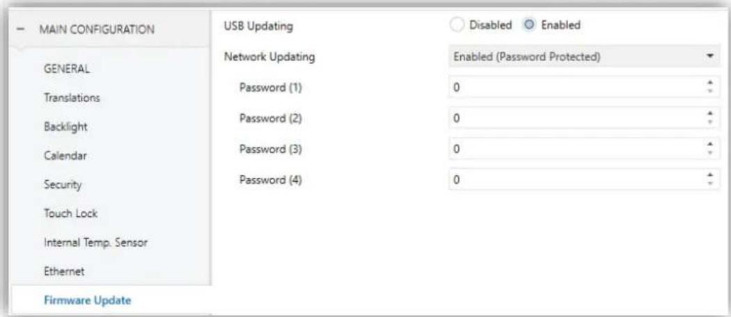
Figure 49 Firmware Update (Main Configuration)
USB Updating: "Enabled" (default option) or "Disabled".
Network Updating (Z41 Pro / Z41 COM): "Enabled" (default option), "Disabled" or "Enabled (Password Protected)". The latter brings the option to restrict the updates via Ethernet to those who can provide the required password to the update tool before the firmware download starts. This password, consisting in four numerical figures, needs to be set in ETS by the integrator.
Note: reading the specific user manual of the firmware update process available at the Zennio webpage is encouraged, as it contains particular remarks regarding the password protection.
3.2.13 VoIP CALLS (Z41 COM)
In this tab is possible to set the network configuration for voice calls as well as enabling the Video Intercoms and Internal Calls.
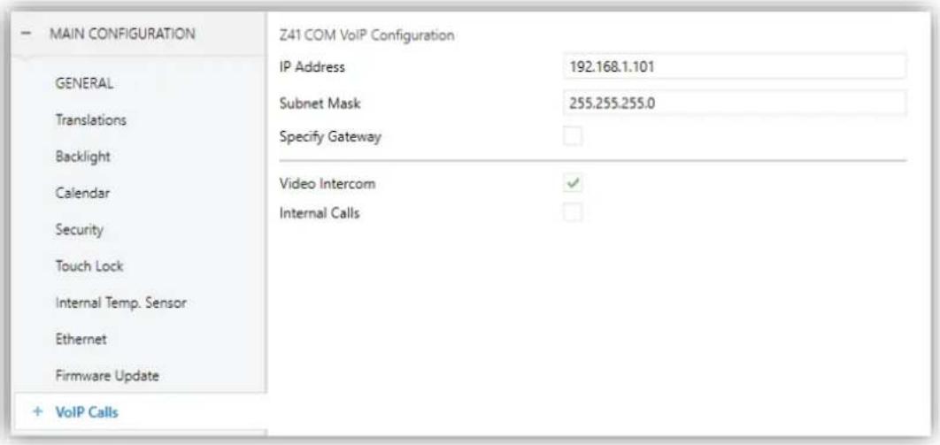
Figure 50 VoIP Calls. Main Configuration.
Z41 COM VoIP Configuration:
IP Address: IP address that is used to uniquely identify the Z41 COM for VoIP functionality. This is the IP address that will be indicated on the outdoor unit (GetFace IP) and on a contact on another screen to make an internal call.
Note: it is recommended to set this IP address out of the range of addresses assigned by the home router to prevent possible conflicts with the IP address visible to the internet.
Subnet Mask: must match the mask of the network to which Z41 COM belongs.
➢ Specify Gateway: when enabled permits introduce a gateway. It is required when the outdoor unit and/or any contact for internal calls are in a different network from Z41 COM.
- Video Intercom: enables or disables the "Video Intercom" tab where the video intercom outdoor units (GetFace IP) can be configured. See section 3.2.13.1 for details.
Internal Calls: enables or disables the "Internal Calls" tab where the calls to other Z41 COM can be configured. See section 3.2.13.2 for details.
Important: In order to correctly update the changes made to the network configuration after downloading, the steps below are required:
- After downloading, wait for the screen synchronization to complete.
- Once Z41 COM has started in normal operating mode, perform a power failure.
Note: When enabling and configuring a Video Intercom and/or an Internal Call, the Z41 COM will receive calls but it is required necessary to parameterise a box as a Video Intercom and/or Internal Call to access his call log and also for the visualization of the image of the camera on private Video Intercoms and/or be able to make calls to other contacts. For further information see section 3.6.2.5.13 y 3.6.2.5.14.
3.2.13.1 VIDEO INTERCOM
After enabling "Video Intercom" in the "VoIP Calls" screen (section 3.2.13), a new tab will be incorporated into the tree on the left.

Figure 51 Video Intercom. VoIP Calls.
Default Ringtone: allows selecting the sound Z41 COM will emit when a call from an outdoor unit is received. There are seven different ringtones available. The ringtone selected in this parameter will be the one applied after downloading, but it can be modified later from the configuration page.
Number of tones: allows selecting the number of tones that Z41 will sound when a call from an outdoor unit is received.
Outdoor Unit n: checkbox that enables a new tab with the same name in the left menu where each video intercom is configured (see section 3.3). The following objects are also enabled:
➢ “[VoIP] “Do Not Disturb” Mode”: 1-bit object to activate or deactivate the do not disturb mode.
➢ “[VoIP] Ringtone Volume”: 1-byte object to change the ringtone volume (0-100%).
➢ “[Video Intercom] Ringtone”: 1-byte object to change the ringtone of a call made from an external unit. Seven values available: 0 = Ringtone 1; 1 = Ringtone 2; ... ; 6 = Ringtone 7.
➢ “[Video Intercom] Synchronization”: 14-byte object for sharing information between different Z41 COM linked to the same GetFace IP. Therefore, this object should be linked to the same group address in each Z41 COM that require to be synchronized.
Through this object is notified to the bus if a call has been attended, muted, rejected or if the call log has been consulted (for removing the notification in case there was a not attended call, see Figure 22).
➢ “[Video Intercom] Incoming Call”: 1-bit object which is sent with value ‘1’ when Z41 COM receives a call from an outdoor unit and with value ‘0’ when the call ends.
➢ “[Video Intercom] Play Ringtone”: when this object receives the value “1”, the ringtone is reproduced one time.
3.2.13.2 INTERNAL CALL
After enabling "Internal Call" in the "VoIP Calls" screen (section 3.2.13), the following parameters can be configured:

Figure 52 Internal Call. VoIP Calls.
Z41 COM Configuration:
My ID: Z41 COM identifier code required to establish communication with other screens.
Important:
• This field must not contain spaces or characters: >, <, ·, [, ], (, ), &, %, ;.
- In order to update the My ID field of an internal call after downloading, the steps below are required:
- After downloading wait for the screen synchronization to complete.
- Once Z41 COM has started in normal operating mode, perform a power failure.
Page Title: Incoming Call / Outgoing Call / Ongoing Call: titles of the different internal calls dialogs.
Default Ringtone: allows selecting the sound Z41 COM will emit when a call from another Z41 COM is received. There are seven different ringtones available. The ringtone selected in this parameter will be the one applied after downloading, but it can be modified later from the configuration page.
Number of tones: allows selecting the number of tones that Z41 will sound when a call from another Z41 COM is received.
- Import Contacts from USB: if this option is selected, the contact list should be configured and imported as described in section 2.12.2.2.2
- Contact n: up to 7 contacts can be enabled. A new tab ("Internal Call n") will be added in the left tree for each contact enabled.
When the option “Import Contacts from USB” or “Contact n” is enabled, the following objects, in addition to “[VoIP] “Do Not Disturb” Mode” and “[VoIP] Ringtone Volume” already mentioned (see section 3.2.13.1), are shown:
➢ “[Internal Call] Ringtone”: 1-Byte object to change the ringtone of internal call. Seven values available: 0 = Ringtone 1; 1 = Ringtone 2; ... ; 6 = Ringtone 7.
3.2.14 NTP (Z41 PRO AND Z41 COM)
After enabling "Synchronize Time/Data via NTP" from "General" screen (see section 3.2.1), a new tab will be incorporated into the tree on the left.
The "NTP" tab allows configuring the time zone and NTP server to automatically update the internal clock of Z41 Pro / COM.

Figure 53 NTP (Main Configuration).
Time Zone: dropdown list for selecting a time zone from the Coordinated Universal Time (UTC) standard. "(UTC) Coordinated Universal Time" is the default option, which corresponds to GMT+00 (Greenwich Mean Time standard).
NTP Server: NTP server for Z41 Pro / Z41 COM internal clock synchronization. "0.pool.ntp.org" is the default server, which belongs to NTP Pool Project's servers.
Note: it is recommended to use the specific server of the continental zone where the installation is. For example, "0.europe.pool.ntp.org" for Europe or "uk.pool.ntp.org" for United Kingdom. Please refer to www.pool.ntp.org for further information.
3.3 OUTDOOR UNIT n (Z41 COM)
After enabling "Outdoor Unit n" in the "Video Intercom" subtab (section 3.2.13.1), a new tab will be incorporated into the tab tree.

Figura 54 Outdoor Unit n. Configuration
The parameters available are:
Name: title of the call dialogs and the call log.
• Type: "Private" or "Community". The private type allows accessing at any time to the visualization of images from the camera of the outdoor unit. The community type does not.
The Outdoor Unit Is in a Different Network: required when Z41 COM and GetFace IP are in different networks. When enabled, two parameters appear:
➢ Outdoor Unit ID: numerical identifier of GetFace IP (field Phone Number (ID), in Services → Phone).
IP Address: IP address of GetFace IP.
Note: It is the IP address set in "Static IP Address" field in System → Network → Basic, provided that it has been set manually and not by DHCP. I the option Use DHCP Server is enabled, the IP address can be found out by pressing the main button of the unit 5 times after starting.
Define ID: when enabled the following parameter appear:
➢ Outdoor Unit ID: numerical identifier of GetFace IP (field Phone Number (ID), in Services → Phone).
Note:
- This parameter is only available when the parameter The Outdoor Unit is in a Different network is disabled.
- This field must not contain spaces or characters: >, <, ·, [, ], ( , ), &, %, ;
Number of Doors: up to 3 doors per outdoor unit.
Important: the Door concept in Z41 COM refers to the switches configured in GetFace IP in section Hardware → Switches.
Opening Settings
HTTP Command: the order to open a door will be sent via a HTTP command. When enabled, the following parameters appear:
- Secure Opening: allows setting a username and password required to send through the HTTP command to open de door in order to increase the security (must match with the ones set in GetFace IP in section Services → HTTP API).
KNX Object: enables the 1-bit object “[VI n] Switch X” by means of which the output of a KNX actuator with the door lock connected to it can be controlled. It is possible to choose the value of the object that will open the door (“1 = Open” or “0 = Open”).
Enable KNX Objects to Trigger Opening: enables the 1-bit object “[VI n] Trigger Switch n” which can open the door by writing on the KNX object. Choosing the value of the object that will open the door is possible (“1 = Open” or “0 = Open”).
Important: For safety reasons, it is recommended not to use this communication object or to use it under the responsibility of the integrator.
• Automatic Door Opening (DOORMATIC): allows opening the doors automatically when receiving a call.
➢ Door n: door/s responding to the automatic opening.
Initial Status after ETS Download: sets whether the automatic opening is enabled or not after ETS Download. It also can be changed at runtime through the object “[VI n] Enable Automatic Door Opening”.
➢ Disable if “Do Not Disturb” Mode Is Active: disables the automatic door opening when do not disturb mode is active.
➢ Opening Delay: allows setting a time from 0 to 255 seconds after which the automatic door opening command will be sent.
For further information about the configuration of Z41 COM and external units GetFace IP, please refer to the Manual for Video Intercom Setting (Z41 COM / Z70 + GetFace IP Configuration Guide) and/or GetFace IP user manual (ZVP-CAM o ZVP-WOCAM) available at www.zennio.com.
3.4 INTERNAL CALL (Z41 COM)
After enabling "Internal Call n" in the "Video Intercom" subtab (section 3.2.13.2), a new tab will be incorporated into the tab tree:

Figura 55 Internal Call. Configuration.
The parameters available are:
Name: name shown in the contact list (see Figure 142).
ID: contact identifier. If the contacts are imported via USB, this field corresponds to the sipID.
Important: It must match the My ID parameter configured in the "Internal call" tab of the Z41 COM to which the contact refers (see section 3.2.13.2).
IP Address: IP Address of the contact
Important: It must match the IP address in the "VoIP Calls" tab of the Z41 COM to which the contact refers (see section 3.2.13).
• Different Network: this option must be enabled when the contact is in a different network. In this case it is necessary to indicate the gateway in the "VoIP Calls" tab (see section 3.2.13).
3.5 MENU
The Menu tab contains only one screen, Configuration.
3.5.1 CONFIGURATION

Figure 56 Configuration (Menu) (Vertical)
If the screen orientation is set horizontally (see section 3.2.1), the title field is divided into two maximum 10-character fields (instead of one maximum 20-character field).

Figure 57. Configuration (Menu) (Horizontal)
The Configuration screen, under the Menu tab, permits configuring the Menu page itself, as well as a set of general options related to the enabled pages of controls that can be accessed from the Menu page.
The parameters available are:
• Title: text field that defines the title that will be shown on the top of the Menu page.
Automatic Page Shaping: dropdown list that allows choosing whether the boxes in the Menu page should be automatically distributed (option "Yes") depending on the number of boxes configured or be displayed as a static 2x4 grid (option "No"). See section 2.10.
Default Page: dropdown list that sets the page (Menu, or any of the general-purpose pages) that will behave as the default page. This page will be the one shown after one minute of inactivity. If the page selected has not been enabled or it is protected with password, the menu page will be shown.
In addition, one checkbox is shown per general-purpose page (that is, pages 1 to 12), as well as one more checkbox for the Configuration page. Each of these checkboxes will allow enabling or disabling the corresponding page in the device – a specific ETS tab will appear upon the activation of a page.
3.6 PAGE n
When any of the general-purpose pages is enabled from the Configuration screen under the Menu tab, a new tab named Page n will appear, where n is the number of the page.
Under this tab, one screen (Configuration) will be initially displayed to let the integrator enable or disable each of the boxes in the page. Depending on that, more parameter screens will appear.
Note: figures in this section will show the parameters of a certain page (for instance, page 1) or a certain box (for instance, box 1). The parameters for other pages or boxes are totally analogous.
3.6.1 CONFIGURATION
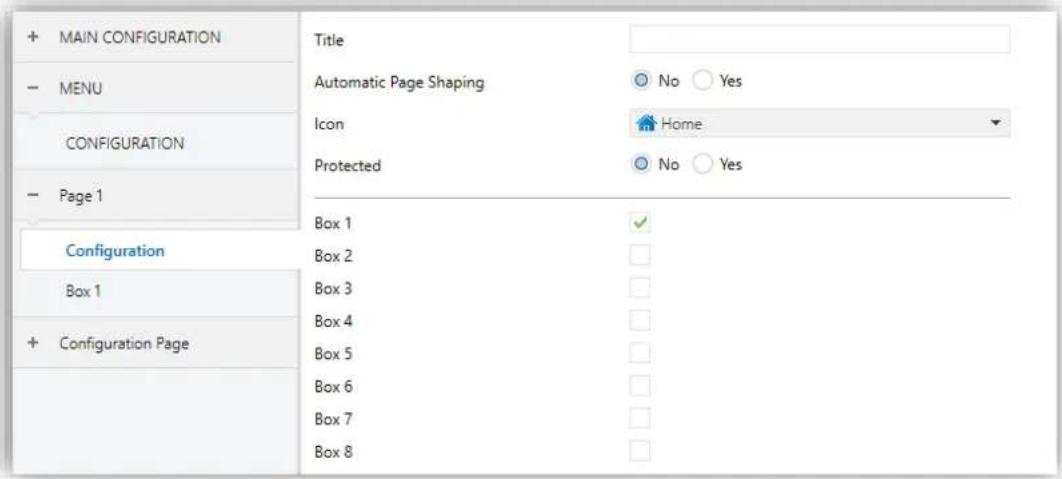
Figure 58 Configuration (Page n)
This screen contains the following parameters:
• Title: text field that sets the title shown on the top of the Menu page.
• Automatic Page Shaping: dropdown list that allows choosing whether the boxes in the Menu page should be automatically distributed (option "Yes") depending on the number of boxes configured or be displayed as a static 2x4 grid (option "No"). See section 2.10.
- Icon: sets the icon that will represent the page in the Menu page.
Note: a list with all icons available can be found in document "Z41 Icon list", available at www.zennio.com.
- Protected: sets whether the page will be password-protected or not. Depending on the security levels configured (one or two; see section 3.2.8) this list will contain the following options:
One level:
No: the page will not be protected by password. All users can access it.
Yes: the page will be protected by password. Users will be asked to type the password when trying to access it.
Two levels:
No: the page will not be protected by password. All users can access it.
Level 1: the page will implement security level 1. To access it, users will be required to enter password 1 or password 2.
Level 2: the page will implement security level 2. To access it, users will be required to enter password 2.
Finally, eight checkboxes are provided to let the integrator enable or disable each of the eight boxes in the page. When enabled, every box will have its own parameter screen (Box i) under the corresponding Page n tab. The next section explains the parameterisation process of these boxes.
3.6.2 BOX i
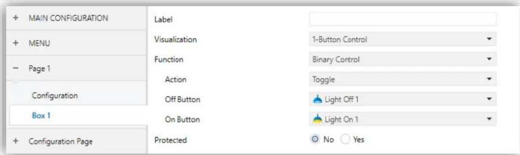
Figure 59 Box i (Page n)
This screen contains the following parameters common to all type of boxes:
Label: identifying title for the box.
Visualization: box format, which may be: Indicator (default option; the box will simply work as a status indicator), 1-button control (the box will work as a one-button control), 2-button control (the box will work not only as a status indicator, but also as a two-button control), Climate control (the box will act as a climate indicator and a climate control) or Other (the box will implement some other functionality).
Depending on the Visualization type selected, the parameters below will change. The following sections explain the available parameters depending on the visualization type selected.
- Protected: sets whether the control will be password-protected or not (does not apply to indicator type boxes). Depending on the security levels configured (one or two; see section 3.2.8) this list will contain the following options:
One level:
No: the box will not be protected by password. All users can access it.
Yes: the box will be protected by password. Users will be asked to type the password when trying to access it.
Two levels:
No: the box will not be protected by password. All users can access it.
➢ Level 1: the box will implement security level 1. To access it, users will be required to enter password 1 or password 2.
Level 2: the box will implement security level 2. To access it, users will be required to enter password 2.
When selecting the protection to controls of type macro, logical function or scheduler, one more parameter appears:
Protected
Protect
○ No ○ Yes
○ Both Buttons ○ Only Configuration Button
Figure 60 Protection parameters of macro, logic function and scheduler controls.
Protect: determines if the password protection will apply to both buttons ("Both Buttons") or only o the configuration button ("Only Configuration Button"). The second case allows triggering the macro without the password restriction.
Important: macros will in any case allow setting actions corresponding to password-protected boxes (see section 3.6.2.5 for details about the configuration of these type of controls).
3.6.2.1 INDICATOR

Figure 61 Indicator (Box)
Boxes configured as indicators permit implementing a set of different functions. The desired function must be selected through the Function parameter. The available functions and the related parameters are:
3.6.2.1.1 Binary Indicator (Icon)
The box will behave as a binary state indicator. Each of the two states will be shown in the box through the selected icon. When this function is assigned to the box, the [Pn][Bi] Binary indicator communication object become available, as well as the parameters that permit selecting the icon to be displayed when the object acquires the value "0" (Icon Off) and the icon to be displayed when it acquires the value "1" (Icon On).

Figure 62 Binary Indicator (Icon)
Therefore, when the device receives the values "0" or "1" through the aforementioned object, the box will show one icon or another.
Note: a list with all icons available can be found in document "Z41 Icon list", available at www.zennio.com.
3.6.2.1.2 Binary Indicator (Text)
The box will behave as a binary state indicator. Each of the two states will be shown in the box through a different label. When the box is assigned this function, the [Pn][Bi] Binary indicator object will become available, as well as the parameters that permit typing the text to be shown when the object receives a "0" (Text Off) and that to be shown when it becomes "1" (Text On).
Therefore, when the device receives the values "0" or "1" through the aforementioned object, the box will show one text or another.

Figure 63 Binary Indicator (Text)
3.6.2.1.3 Enumerated Indicator (Icon)
The box will behave analogously to the case of the Binary indicator, (Icon) however, it will be possible to distinguish up to 6 states (configurable through the # Enums parameter) instead of only two. The states will be determined by the reception of any values between 0 and 255, instead of only values 0 and 1.

Figure 64 Enumerated Indicator (Icon)
When this function is assigned to the box, a 1-byte communication object, [Pn][Bi] Enumerated Indicator, will become available as well as two more parameters (Value and Icon) for each of the states to be distinguished. This allows setting which icon will
be shown in the box upon the reception of which value through the communication object.
Example: a three-state enumerated indicator ("3" under "# Enum") is parameterised as follows:
Value 1 = "1" Icon 1 = "One"
Value 2 = "3" Icon 2 = "Two"
Value 3 = "5" Icon 3 = "Three"
When the [Pn][Bi] Enumerated Indicator object receives the value "1", the box will show icon "One". When it receives the value "3", icon "Two" will be shown. And when it receives the value "5", icon "Three" will show. In case of receiving any other value, no icon will be shown.
3.6.2.1.4 Enumerated Indicator (Text)
The box will behave analogously to the case of the Binary indicator (Text) however it will be possible to distinguish up to 6 states (configurable through the # Enums parameter) instead of only two. The states will be determined by the reception of any values between 0 and 255, instead only by values 0 and 1.
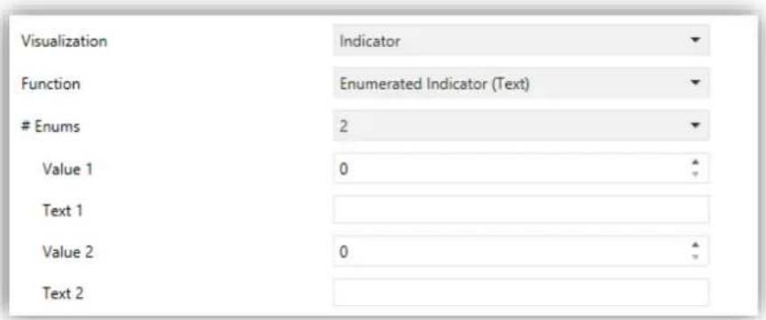
Figure 65 Enumerated Indicator (Text)
When this function is assigned to the box, one 1-byte communication object, [Pn][Bi] Enumerated Indicator, will become available as well as two additional parameters (Value and Text) for each of the states to be distinguished. This allows setting which texts will be displayed in the box upon the reception of which values through the communication object.
3.6.2.1.5 Numerical Indicators

Figure 66 1-Byte Indicator (Unsigned Integer)
The remaining functions under Indicator are shown in Table 2. Numerical indicators
. In all of these cases, the box will behave as a numerical state indicator that permanently displays the value of a certain communication object, which is enabled when the function is assigned to the box.
| Function | Range | Related object |
| 1-byte (unsigned int.) | 0–255 | [Pn][Bi] 1-byte unsigned int indicator |
| 1-byte (signed int.) | -128 – 127 | [Pn][Bi] 1-byte signed int indicator |
| Percentage indicator | 0% – 100% | [Pn][Bi] Percentage indicator |
| 2-byte (unsigned int.) | 0 – 65535 | [Pn][Bi] 2-byte unsigned int indicator |
| 2-byte (signed int.) | -32768 – 32767 | [Pn][Bi] 2-byte signed int indicator |
| 2-byte (floating point) | -671088.64 – 670433.28 | [Pn][Bi] 2-byte float indicator |
| 4-byte (signed integer) | -2147483648 – 2147483647 | [Pn][Bi] 4-byte Signed Int Indicator |
| 4-byte (floating point) | -3.403E-38 – 3.403E-38 | [Pn][Bi] 4-byte Float Indicator |
Table 2. Numerical indicators
The table also reflects the allowed value ranges and the name of the object for each case.
In all cases the integrator will be shown a text field (Unit), empty by default, that permits specifying the measuring units (up to 6 characters) of the displayed value. For percentage indicators, the symbol % always will be displayed as unit.
In the particular case of the floating point indicators (2-byte or 4-byte), the device will dynamically adjust the number of the decimal figures shown depending on the order of magnitude of the current value: two for values greater than 0 and lower than 0.1; one for values between 0.1 and 100; and none for other cases (and analogously for negative values).
All these numerical indicators incorporate an additional parameter, Save Log? In case of enabling this option (“Yes”), any changes in the value of the indicator will be continuously saved to an internal log file, so the final user can be afterwards offered a visual representation that reflects the chronological evolution of such value with several levels of detail, depending on the parameterisation:

Figure 67 Plot Zoom Levels
Boxes for which this option has been enabled will show a small icon overlaid on their upper left corner.

Figure 68 Indicator implementing the Log Function
Boxes showing this icon let the user press them, which will bring up a pop-up window similar to Figure 69. If password protection is enabled, the user must enter the correct password in order to view the graph dialog.

Figure 69 Graphical representation of the Log File
The graph (where the vertical scale will dynamically adapt to the values being represented) shows the chronological evolution of the value, with higher or lower detail (hourly, daily, weekly or monthly, depending on the zoom levels enabled and on the level selected by the user through the on-screen magnifying glass control; see Figure 70). In the case of the lower detail levels, the graph will show the average values per time unit (day or month) as well as the maximum and minimum values.
Finally, the bin icon (lower right corner of the screen) lets the user, by performing a long press the contents will be deleted from the log file, thus setting the values of the monitor to zero.

Figure 70 Different Detail Levels (log file)
Note: large values (especially 2-byte and 4-byte values) may be rounded in order to make them fit on the screen. In some cases, the measuring units defined in parameters may show with a prefix (kilo, Mega, Tera, etc.).
3.6.2.1.6 14-Byte Text Indicator

Figure 71 14-byte text indicator
The box will show the text received through the communication object “[Pn][Bi] 14-Byte Text Indicator”.
Note: objects associated to the text indicator are stored in non-salved zone, so its value will not be maintained after a restart.
3.6.2.2 1-BUTTON CONTROL
Boxes configured as 1-button controls show one centred button and a title.

Figure 72 1-Button Control (Box)
The desired function must be selected through the Function parameter. The available functions and the parameters related to each are:
3.6.2.2.1 Binary Control
The central button of the box will react to user presses by sending a binary value to the bus through the [Pn][Bi] Binary control object, which turns visible as soon as this function is assigned to the box.

Figure 73 Binary control
On the other hand, Action permits setting what value will be sent to the bus through the mentioned object, and on what events. The options are:
Toggle: pressing the button will cause an alternate sending of the values "1" and "0". Particularly, on the first press one "1" will be sent; on the second, one "0"; on the third, one "1"; and so on.
➢ 0: one "0" will be sent whenever the button is pressed.
➢ 1: one "1" will be sent whenever the button is pressed.
Short 1 – Long 0: short presses will cause the sending of the value “1”, while long presses will cause the sending of the value “0”.
Short 0 – Long 1: inverse to the previous case.
Hold 0 – Release 1: one "0" will be sent when the button press starts, and one "1" as soon as the button is released.
Hold 1 – Release 0: one "1" will be sent when the button press starts, and one "0" as soon as the button is released.
Finally, the dropdown list next to Button off and Button on (or Button (in the middle) when only one value is sent) permits selecting the icon to be displayed inside the button for each value.
Note: a list with all icons available can be found in document "Z41 Icon list", available at www.zennio.com.
3.6.2.2.2 Numerical Constant Controls

Figure 74 1-byte constant (unsigned int)
If the box is assigned any of the remaining "constant" control options, the central button in the box will react to user presses by sending a certain numerical value, which is required to be specified under Constant value.
Table 3. Numerical constant controls.
shows, for every available Function, the permitted value range and the name of the object through which the values are sent to the bus.
| Function | Range | Object |
| 1-byte constant (unsigned int.) | 0 – 255 | [Pn][Bi] 1-byte unsigned int control |
| 1-byte constant (signed int.) | -128 – 127 | [Pn][Bi] 1-byte signed int control |
| Constant percentage value | 0% – 100% | [Pn][Bi] Percentage control |
| 2-byte constant (unsigned int.) | 0 – 65535 | [Pn][Bi] 2-byte unsigned int control |
| 2-byte constant (signed int.) | -32768 – 32767 | [Pn][Bi] 2-byte signed int control |
| 2-byte constant (float) | -671088.64 – 670433.28 | [Pn][Bi] 2-byte float control |
Table 3. Numerical constant controls.
Finally, the dropdown list next to Button (in the middle) permits selecting an icon to be displayed inside the button.
Note: a list with all icons available can be found in document "Z41 Icon list", available at www.zennio.com.
3.6.2.2.3 Scene Control

Figure 75 Scene control
In this case, the central button of the box will react to user presses by sending a scene value to the KNX bus through the [General] Scenes: send object, which is enabled by default. Parameter Scene number permits specifying the number of the scene (1 – 64) to be sent. Moreover, Action (which shows the options "Run" and "Run and save") sets whether the device will only send scene execution orders (after a short press) or if it will be possible, in addition to sending execution orders upon short presses, to send scene save orders in the case of a long press.
Finally, the dropdown list next to Button (in the middle) permits selecting an icon to be displayed inside the button.
Note: a list with all icons available can be found in document "Z41 Icon list", available at www.zennio.com.
3.6.2.3 2-BUTTON CONTROL
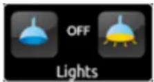
Figure 76 2-button control (Box)
Boxes configured as 2-button controls consist in an indicator and two buttons that, when touched, trigger the sending of an action to the KNX bus through a certain object. This category also includes some specific controls such as light dimming and shutter control.
As a general rule, most of the 2-button controls permit configuring a pair of parameters, Left button and Right button, each containing a dropdown list for the selection of the icons to be displayed inside the buttons in the box.
Notes:
A list with all icons available can be found in document "Z41 Icon list", available at www.zennio.com.
- When multiple presses are made consecutively on the buttons of a control that regulates (e.g. increases / decreases) the value of a certain variable, only the final value selected by the user will be sent to the bus, to prevent an unnecessary bus traffic due to all the intermediate values.
On the other hand, the Function parameter contains a dropdown list for the selection of the particular two-button control type to be assigned to the box. The available options (and their related parameters) are:
3.6.2.3.1 Binary Control (Icon)
When the user touches the buttons, a binary value will be sent through the [Pn][Bi] Binary control object, while the status object, [Pn][Bi] Binary indicator, will determine the icon shown in the box.

Figure 77 Binary Control (Icon)
The parameters available are:
• Action: sets the value to be sent on button touches. This can be "Left 0, Right 1" (by default) or "Left 1, Right 0".
- Off Icon and On Icon: dropdown lists for the selection of the icons that will represent the two states (0 / 1) of the [Pn][Bi] Binary Indicator object, which gets automatically updated whenever an order is sent through the control object. It may also receive values from the bus.
3.6.2.3.2 Binary Control (Text)

Figure 78 Binary Control (Text)
When the user touches the buttons, a binary value will be sent through the [Pn][Bi] Binary Control object, while the status object, [Pn][Bi] Binary Indicator, will determine the text that will be shown in the box.
The parameters available are:
- Action: sets the value to be sent on button touches. This can be "Left 0, Right 1" (default) or "Left 1, Right 0".
- Text Off and Text On: indicative texts that will be shown in the box depending on the state (0 / 1) of the [Pn][Bi] Binary Indicator object, which gets automatically updated whenever an order is sent through the control object. It may also receive values from the bus.
3.6.2.3.3 Enumerated Control (Icon)
The box will behave analogously to the case of the Binary control (Icon) however it will be possible to distinguish up to 6 states (configurable through the # Enums parameter) instead of only two. The states will be determined by the reception of any values between 0 and 255, as the control ([Pn][Bi] Enumerated Control) and the status ([Pn][Bi] Enumerated Indicator) objects are not binary but 1-byte objects.
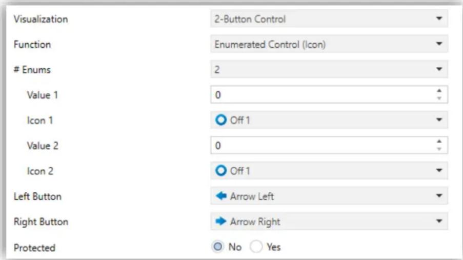
Figure 79 Enumerated Control (Icon)
The parameters available are:
-
Enums: number of states (up to 6) that will be distinguished. For every distinguished state, the parameters Value and Icon will become available, in order to relate every significant value of the communication object to a certain icon that will represent it. Value j: numerical value (0 - 255) that will be sent through the control object when the user, after pressing the buttons, sets the control box to state j.
- Icon j: indicative icon that will be displayed in the box when the status object (which gets automatically updated whenever a control order is sent, although it may also receive values from the bus) acquires the numerical value defined in the above parameter.
3.6.2.3.4 Enumerated Control (Text)
The box will behave analogously to the case of the Binary control (Text) however it will be possible to distinguish up to 6 states (configurable through the # Enums parameter) instead of only two. The states will be determined by the reception of any values between 0 and 255, as the control ([Pn][Bi] Enumerated Control) and the status ([Pn][Bi] Enumerated Indicator) objects are not binary but 1-byte objects.

Figure 80 Enumerated Control (Text)
The parameters available are:
-
Enums: number of states (up to 6) that will be distinguished. For every distinguished state, the parameters Value and Icon will become available, in order to relate every significant value of the communication object to a certain icon that will represent it. Value j: value (0 - 255) that will be sent through the control object when the user, after pressing the buttons, sets the control box to state j.
Text j: indicative text that will be displayed in the box when the status object (which gets automatically updated whenever a control order is sent, although it may also receive values from the bus) acquires the numerical value defined in the above parameter.
3.6.2.3.5 Numerical Controls
If the box is assigned any of the six numerical functions, user touches over the buttons will trigger the sending of a certain numerical value to the bus (which will be progressively increased or decreased with every touch on one button or the other) through the control object, while the box itself will permanently reflect the current value of the status object (which gets automatically updated after a control order is sent, although it may also receive values from the bus).
Table 4. Numerical Controls
shows, for each of the six functions, the permitted value range and the name of the control and status objects.
| Range | Control object | Status object |
| 1-byte (unsigned int.) | ||
| 0 – 255 | [Pn][Bi] 1-byte unsigned int control | [Pn][Bi] 1-byte unsigned int indicator |
| 1-byte (signed int.) | ||
| -128 – 127 | [Pn][Bi] 1-byte signed int control | [Pn][Bi] 1-byte signed int indicator |
| Percentage control | ||
| 0% – 100% | [Pn][Bi] Percentage control | [Pn][Bi] Percentage indicator |
| 2-byte (unsigned int.) | ||
| 0 – 65535 | [Pn][Bi] 2-byte unsigned int control | [Pn][Bi] 2-byte unsigned int indicator |
| 2-byte (signed int.) | ||
| -32768 – 32767 | [Pn][Bi] 2-byte signed int control | [Pn][Bi] 2-byte signed int indicator |
| 2-byte (float) | ||
| -671088.64 – 670433.28 | [Pn][Bi] 2-byte float control | [Pn][Bi] 2-byte float indicator |
Table 4. Numerical Controls
For all the six functions, the parameters available are:

Figure 81 1-Byte (Unsigned Int.) 2-Button Control
• Action: sets which of the two buttons will increase the current numerical value and which will decrease it on user presses. The allowed options are "Left Decrease, Right Increase" (default) and "Left increase, Right Decrease".
Initial Value: sets which value from the permitted range will be assumed by the control prior to any button presses. It is always 0 by default.
• Minimum Value: sets which value from the available range will be the minimum value permitted by the control after a number of presses on the decrease button.
• Maximum Value: sets which value from the available range will be the maximum value permitted by the control after a number of presses on the increase button.
- Short Increment: sets the increase or decrease to be applied to the current value on every short press over the increase or decrease buttons, respectively (i.e., the smaller the increment is, the more presses will be required). It is 1 by default, except for the case of the 2-byte floating point control, where it is 0.5.
- Long Increment: sets the increase or decrease to be applied to the current value on every long press over the increase or decrease buttons, respectively (i.e., the smaller the increment is, the more presses will be required). It is 10 by default, except for the case of the 2-byte floating point control, where it is 1.
Note: if the increments configured are too small, certain button touches may not cause a perceptible value change on the indicator, due to precision restrictions of the KNX standard.
3.6.2.3.6 Two-button Scene Control
Analogously to the 1-button scene control, 2-button scene controls allows sending the KNX bus a scene value through the [General] Scenes: send object, however in this case there will be two buttons in the box, each of which can be configured independently.
Through the Scene parameter it is possible to assign each of the two buttons (left / right) the number of the scene to be sent (1 - 64). In addition, Action (which permits the options "Run" and "Run and save") lets the integrator set whether the device will only send execution orders for the specified scene (after a short press), or it will possible, apart from sending execution orders on short presses, to also send save orders for such scene, in the case of performing a long press on the button
Last, the dropdown list under Button Icon sets the icon to be displayed by the buttons.
Note: a list with all icons available can be found in document "Z41 Icon list", available at www.zennio.com.

Figure 82 2-Button Scene Control
3.6.2.3.7 Shutter Control

Figure 83 Shutter Control
Shutter controls permit sending move up, move down, stop or step shutter orders to the KNX bus by pressing the buttons in the box. In addition, the box will contain an indicator that will permanently show, as a percentage, the value of the status object.
The only specific parameter for this function is:
• Action: sets which of the two buttons will send the move up orders and which the move down orders. Options are "Left Down, Right Up" (default) and "Left Up, Right Down".
Setting up a box as a shutter control enables three communication objects, [Pn][Bi] Shutter Position (1 byte), [Pn][Bi] Move Shutter and [Pn][Bi] Stop Shutter (both, binary objects). The first one acts as the status object, which determines the value shown in the box; it will be necessary to link it to the analogous object from the shutter actuator (as it does not get automatically updated on user presses) so it receives the value 100% when the shutter is completely down, and the value 0% when it is totally up. On their side, control orders will be sent through one of the two remaining objects:
Orders to move the shutter up/down (completely) are sent through [Pn][Bi] Move Shutter after a long press on the corresponding button. Value "0" represents the move up order, while "1" represents the move down order.
Orders to perform a step movement (value "0" for steps up and "1" for steps down) are sent through [Pn][Bi] Stop Shutter after a short press on the corresponding button. If the shutter was already in movement, these orders are interpreted by the actuator as a stop order.
State indicator: enables (by default) or disables the shutter status indicator.
3.6.2.3.8 Light Dimming

Figure 84 Light Dimming.
The light control function permits making use of the two buttons in the box to send orders to a light dimmer, either through a binary object or through a 4-bit object. Moreover, the box will permanently display the current value of the dimming status object, which needs to be linked to the analogous object from the dimmer (as it does not get automatically updated on button presses).
The parameters available are:
• Action: sets which of the two buttons will send the "turn on" orders and which the "turn off" orders. Options are "Left Off, Right On" (default) and "Left On, Right Off".
Dimming Step: sets the increase or decrease in the light level (in terms of percentage) the dimmer must perform with every step order. How step dimming works is detailed below.
Setting up a box as a dimming control brings up the objects [Pn][Bi] Light Indicator (1 byte), [Pn][Bi] Light On/Off (1 bit) and [Pn][Bi] Light Dimming (4 bits). The first one acts as the dimming status object, which is required to be linked to the analogous object from the dimmer and whose value, in percentage, will be permanently reflected in the box. On their side, control orders will be sent through one of the two remaining objects:
After a short press on the "turn on" button, the value "1" will be sent through the [Pn][Bi] Light On/Off binary object, while a short press on the "turn off" button will trigger the sending of the value "0".
When a long press on the "turn on" button takes place, the object [Pn][Bi] Light Dimming will send the light increment order corresponding to the parameterised dimming step, while a stop order (value "8") will be sent through the same object as soon as the user releases the button.
When a long press on the "turn off" button takes place, the object [Pn][Bi] Light Dimming will send the light decrement order corresponding to the parameterised dimming step, while a stop order (value "0") will be sent through the same object as soon as the user releases the button.
Table 5. Dimming Steps
shows the number of steps (that is, of long presses) required for a complete light regulation (from totally off to totally on, or vice versa) depending on the value parameterised as the dimming step.
| Dimming Step | Button Presses Required for Complete Dimming (0 – 100%) |
| (1) 100% | 1 |
| (2) 50% | 2 |
| (3) 25% | 4 |
| (4) 12,5% | 8 |
| (5) 6,25% | 16 |
| (6) 3,1% | 32 |
| (7) 1,5% | 64 |
Table 5. Dimming Steps
Note: most light dimmers implement light step dimming progressively (i.e., sending a dimmer a step order of 25% typically does not imply that the light level is suddenly incremented/decremented by 25%, but a progressive increment or decrement of the light level by 25% which is in fact interrupted if a stop order arrives (such order is sent by Z41 Pro / Lite / COM when the user releases the button). Due to this behaviour, it is advised to parameterise dimming steps of 100%, so that the user can perform a complete dimming (from totally off to totally on, or vice versa) or a partial dimming by simply holding the button and then releasing it as soon as he gets the desired light level, therefore with no need of performing successive long presses for regulations greater than the parameterised step.
3.6.2.4 CLIMATE CONTROL
This category covers a set of functions related to the climate control. The available options for Function (and for the dependent parameters) are as follows:
3.6.2.4.1 Setpoint Control
This function permits controlling the temperature setpoint of an external thermostat by means of a two-button box and of the parameters enabled to that effect: [Pn][Bi] Temperature Control for the control and [Pn][Bi] Temperature Indicator for the status. In addition, the box itself will permanently reflect the value (in °C) of the status object, whose value gets automatically updated after sending control orders (that is, after pressing the buttons), being even possible to receive values from the bus, for example, from the corresponding setpoint status object from the external thermostat.

Figure 85 Setpoint
Therefore, after every press on the temperature increment button, the bus will be sent (through the control object) a certain value, progressively increased on every button press until the parameterisable maximum setpoint value has been reached. Analogously, after every press on the temperature decrement button, the bus will be sent a progressively decreased value until the parameterisable minimum setpoint value has been reached.
The parameters available are:
Action: sets which of the two buttons will permit increasing the setpoint value and which one will permit decreasing it. Options are "Left decrease, Right increase" (default) and "Left increase, Right decrease".
- Setpoint Type: it may be "Absolute" (default), "Relative (1-bit object)" or "Relative (Float Object)".
If the first is selected, the control object will be a 2-byte floating point object and its value will correspond to the actual setpoint value to be sent to the thermostat, being progressively higher or lower as the user touches the control buttons. It is possible to set different increments for short press (short increment) and long press (long increment). On the other hand, the permitted temperature setpoints will be delimited by a maximum value and a minimum value, defined by the so-named parameters.

Figure 86 Absolute Setpoint Control
If the second option is selected (1-bit object setpoint control), the control object will be binary, and it will throw a "0" to the bus whenever the user asks for a setpoint decrement, and a "1" when the user asks for an increment. How much it is incremented or decreased after every order is defined through the offset parameter (which accepts values between 1 and 255 tenths of a degree), thus permitting a consistent self-update of the label in the box after every user press, although the status object will also admit the reception of feedback from the bus, i.e., the updated absolute setpoint value sent from the external thermostat.

Figure 87 Relative (1 Bit) Setpoint Control
Finally, when “Relative (float object)” is selected, the control will send 2-byte floating point values. However, these values will correspond to the particular increment or decrement (or offset) to be applied each time. This offset refers to a base temperature and will always be a multiple of 0.5° C. As the user touches the increase/decrease buttons in the box, this offset will vary, always within a certain range defined through the Minimum Offset and Maximum Offset parameters.

Figure 88 Relative (Float Object) Setpoint Control
Example: suppose the following parameterisation:
- Relative setpoint with a floating point object,
- Minimum offset = -10°C,
- Maximum offset = 10° C.
The objects are linked to those from an external thermostat, which can be supposed to have a base temperature setpoint of 25° C. After the parameter download:
- The first touch on the increase button will trigger the sending of the value "0.5", so that the thermostat sets the setpoint to 25.5° C . This value will be then sent through the status object, and afterwards shown on screen in the corresponding box.
- A second touch will trigger the value "1", after which the setpoint will become 26°C .
- On the third touch, the value sent will be "1.5", so the setpoint will be set to 26.5°C.
And so on until the offset sent becomes 10 (setpoint of 35°C ). Any further presses on the increase button will send the value "10" again, so the setpoint will remain at 35°C , while touching the decrease button for the first time will trigger the sending of the value "9.5", setting the temperature back to 34.5°C . On the second button press, the value "9" will be sent, and the setpoint will become 34°C . And so on until an offset of "-10" (setpoint of 15°C ) is reached. From that moment, any further presses on the decrease button will re-send the value "-10" and the setpoint will remain at 15°C .
Important: the control object for the floating point relative setpoint control has its Write flag enabled with the intention of permitting the reception of feedback from the thermostat, which may reset or modify the status of the offset for any reason at any time. This feedback lets Z41 Pro / Lite / COM update its own value to equal that from the external thermostat. Thinking of the above example, if Z41 Pro / Lite / COM receives the value "0" after having the user performed three presses on the increase button (therefore, after having been sent the value "1.5" to the bus), it will happen that on the forth press the value sent will be "0.5" and not "2".
![graph LR A["Control object"] --> B["Offset"] C["Status object"] --> D["Setpoint T. (status)"] B --> E["Offset (status)"] D --> F["Setpoint T. (status)"]](/content/2026/07/1421749/images/f1f208bacff6631b875022778efecee6f75cb432f3921743ed08b977121e84de.jpg)
Figure 89 Relative (Float) Setpoint Control. Object Linking.
Note: the parameterised setpoint type becomes transparent to the final user, as the aspect of the on-screen box remains the same in all cases. In addition, the setpoint status object is always a 2-byte floating point object and will represent, in any case, the absolute value of the current temperature setpoint.
- Left Button and Right Button: permit selecting the desired icon to be displayed inside each button in the box.
Note: a list with all icons available can be found in document "Z41 Icon list", available at www.zennio.com.
3.6.2.4.2 Mode Control
This function turns the box into a climate mode control.
Two mode control types are possible: Heat / Cool control type and the Extended (HVAC) control type. Selecting the former or the latter is possible through the Mode Type parameter.

Figure 90 Heat/Cool Mode Type
Heat / Cool
Selecting this type of mode control turns the box into a 2-button control one of which will activate the Heat mode, while the other one will activate the Cool mode. A centred indicator will reflect, as an icon, the currently active mode.

Figure 91 Heat/cool Mode (Box)
Two communication objects are also enabled: the [Pn][Bi] Mode Control control object and the [Pn][Bi] Mode Indicator status object. When the user activates the Cool mode, the device will send the value "0" through the control object, while on the activation of the Heat mode the value "1" will be sent. Moreover, the box will automatically commute between one icon and the other every time the user executes a mode change, and also on the reception of a new value (from the bus) through the status object.
Extended
Selecting this type of mode control turns the box into a 2-button control, which permit sequentially commuting among the different HVAC climate modes. A centred indicator will reflect, as an icon, the currently active mode.

Figure 92 Extended Mode (Box)
Up to five modes (Heat, Cool, Auto, Fan and Dry) are available, each of which can be enabled/disabled in ETS by means of the proper checkbox, which permits setting which of all the five extended modes will be included into the sequential scrolling implemented by the buttons.

Figure 93 Extended Mode
When this type of mode control is assigned to the box, two 1-byte communication objects are enabled: the [Pn][Bi] Mode Control control object, and the [Pn][Bi] Mode Indicator status object. Depending on the mode selected by the user, the control object will be sent to the bus a certain value (see Table 6. HVAC Mode vs. Object Value), after which the box will display the icon that corresponds to the new mode. Additionally, if the status object receives from the bus a value that represents any of the modes, the box will adopt the corresponding icon, while if an unrecognised value is received, no icon will be shown.
| Mode | Value sent |
| Heat | 1 (0x01) |
| Cool | 3 (0x03) |
| Auto | 0 (0x00) |
| Fan | 9 (0x09) |
| Dry | 14 (0x0E) |
Table 6. HVAC Mode vs. Object Value
Finally, the Left Button and Right Button parameters permit selecting the icon that will be displayed inside the buttons of the box.
Note: a list with all icons available can be found in document "Z41 Icon list", available at www.zennio.com.
3.6.2.4.3 Fan Control
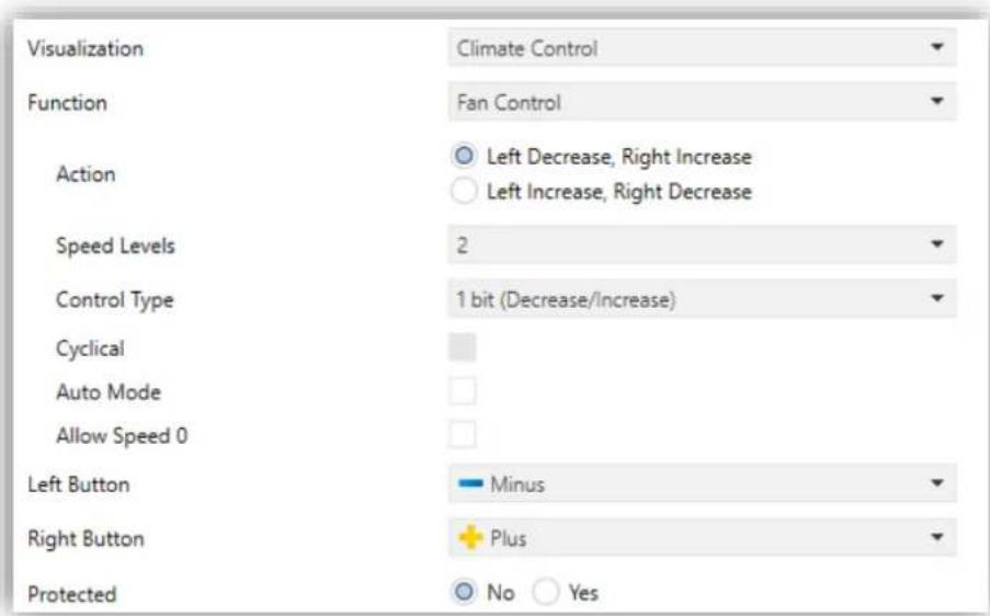
Figure 94 Fan Control
This function implements a 2-button (increase / decrease) fan control, as well as an icon indicator.
When this function is assigned to the box, object [Pn][Bi] Fan Control as well as the [Pn][Bi] Fan Indicator 1-byte status object are enabled. The status object (which needs to be linked to the status object of the fan actuator) will express, as a percentage, the value of the current fan level, which will be represented with a variable icon on the box.
Action: permits setting the increase or decrease actions to one button or another. Options are: "Left: decrease, Right increase" (default) and "Left increase, Right decrease".
• Speed Levels: sets how many speed levels will be available in the control. 1 to 5 levels.
• Control Type: sets the type of the communication objects that will control the fan level.
“1 bit (decrease/increase)”: orders of speed increase/decrease are sent through the one-bit object “[Btn] [X] Fan control (1 bit)”.
“Scaling”: scaling values are sent through the one-byte object “[Btn] [X] Fan control (scaling)”.
“Enumeration”: integer values are sent through the one-byte object “[Btn] [X] Fan control enumerated”.
Cyclical: sets whether scrolling through the speed levels is circular or not. If checked, an increase order in the maximum level switches to the minimum and vice versa (in the minimum level a decrease order switches to the maximum).
Auto Mode: sets whether the fan Auto mode will be available or not. If checked, the following parameters are also shown.
➢ Dedicated Object for Auto Mode: sets how the Auto mode should be activated. In the absence of a dedicated object, the Auto fan mode will be activated by switching to fan level 0.
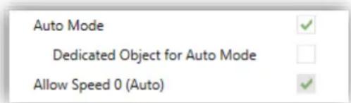
Figure 95 Fan Control – Auto Mode.
In this case (supposing that Speed Levels has been set to "3"), the fan levels that can be navigated through short presses are:
| Auto (0) | Minimum | Medium | Maximum |
On the other hand, marking the checkbox enables the one-bit object "[Btn] [X] Fan control – Auto mode", which will trigger the Auto mode when it receives the value "1" (or "0", depending on the subsequent parameter "Value to Set the Auto Mode").
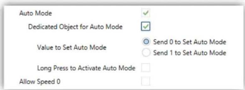
Figure 96 Fan Control – Dedicated Object for Auto Mode.
However, two alternative (and mutually exclusive) methods are possible to activate this mode:
- By short press: the Auto mode can be reached as a further level above the maximum one. In this case the fan levels activated by short presses are (note that speed 0 is optional):
| (0) | Minimum | Medium | Maximum | Auto |
- By long press on any of the buttons of the control (requires checking Long Press to Activate Auto Mode).
A further long press deactivates back the Auto mode and sends the minimum fan level. Instead, a short press deactivates the Auto mode and switches to the next level (or previous, depending on the button). In this case the fan levels reachable through short presses are (speed 0 is optional):
| (0) | Minimum | Medium | Maximum |
Here, the Auto mode is only activated by long press.
- Allow speed 0: sets whether the speed level 0 will be present or not. When the Auto Mode without a dedicated object has been configured, this option will be necessarily activated.
Finally, the Left Button and Right Button parameters permit selecting the icon that will be displayed inside the buttons of the box
Note: a list with all icons available can be found in document "Z41 Icon list", available at www.zennio.com.
3.6.2.4.4 Special Mode Control
Boxes configured as special mode controls include two buttons that let the user sequentially commute between the different special climate modes, as well as an icon indicator that will adopt an aspect or another depending on the currently active special mode.

Figure 97 Special Mode Control (Box)

Figure 98 Special Modes
When this function is assigned to the box, two 1-byte objects ([Pn][Bi] Special Mode Control as the control object, and [Pn][Bi] Special Mode Indicator as the status object) will be enabled. The former will be sending the bus the value that corresponds to the mode that the user selects by touching the buttons (see Table 7. Special Modes vs. Icon vs. Object Value
), while the status object (which can receive values from the bus although it gets self-updated as well on button presses) will determine the indicative icon represented in the
box at any time. If this object receives an unrecognised value from the bus, no icon will be displayed in the indicator.
| Special Mode | Icon | Object Value |
| Comfort |  | 1 (0x001) |
| Standby | [ABGT] | 2 (0x002) |
| Economy |  | 3 (0x003) |
| Protection |  | 4 (0x004) |
| Auto Mode |  | 5 (0x005) |
Table 7. Special Modes vs. Icon vs. Object Value
The remaining parameters for this function are:
- Allow Protection Mode: this parameter permits excluding ("No", default option) or including ("Yes") the "building protection" mode from the special modes listed in the sequential scrolling performed by the buttons.
- Allow Auto Mode: this parameter permits excluding ("No", default option) or including ("Yes") the "auto" mode from the special modes listed in the sequential scrolling performed by the buttons.
- Left Button and Right Button: permit selecting the icon that will be displayed inside the buttons in the box.
Note: a list with all icons available can be found in document "Z41 Icon list", available at www.zennio.com.
3.6.2.5 OTHER
This category involves the following functions, which can be selected through the Function parameter.
3.6.2.5.1 RGB
This function is intended for sending orders to thee-colour LED light regulators, such as LUMENTO X3 RGB from Zennio.

Figure 99 RGB
When the function is assigned to the box, the following parameters come up:
- Object Type: permits selecting what type of object will be used for controlling the light level of the RGB channels. It may be "Three single colour objects (DPT 5.001)" (by default) or "One RGB object (DPT 232.600)". If the former is selected, three 1-byte objects will be enabled (with their Write and Read flags activated, so they can both send regulation orders and receive the status from the regulator) named:
[Pn][Bi] Red Channel
[Pn][Bi] Green Channel
[Pn][Bi] Blue Channel
Control orders will consist in sending the light level (as a percentage) of the different channels through the corresponding objects.
If the second option is selected, only one 3-byte object will be enabled:
[Pn][Bi] RGB Colour
In this case, the light levels of the three channels are sent (and received) concatenated into the above 3-byte object.
Note: if statuses are received while the luminaire performs a regulation, this control may become hardly serviceable until such regulation ends.
- Left Button and Right Button: permit selecting the icon that will be displayed inside the buttons in the box.
Regarding the RGB control boxes themselves, a central label will permanently show, as a percentage, the current light level (which is determined by the channel with the highest current light level). This indicator gets updated automatically as the user interacts with the box, but is also conditioned by the values received from the bus through the already described objects.

Figure 100 RGB (Box)
Moreover, two buttons can be found in the box:
- Short-pressing on the left button it permits commuting between a total absence of light in the three channels, and their respective states previous to the switch-off. Long-pressing it, on the other hand, will make the device send a 4-bit dimming order through object [Pn][Bi] Intensity Dimming, analogously as in a light dimming control (see h) in section 3.6.2.3).
The button on the right, when pressed, launches a pop-up 1 containing colour palette that permits the selection of a light level for every channel, either by touching on any of the pre-set colours, or by separately selecting the level of each channel (R, G, B).

Figure 101 RGB Colour Palette
A set of recently used colours is shown at the bottom of the palette. These colours refer to those recently used within that particular box.
3.6.2.5.2 RGBW
The RGBW control is entirely analogous to the above RGB control, although it also lets controlling a specific fourth channel for white, in case such feature is supported by the dimmer, as in Lumento from Zennio.
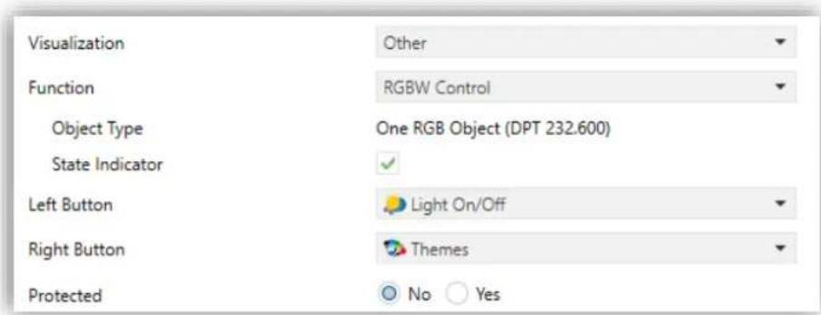
Figure 102 RGBW
Therefore, the functionality is similar to that of the RGB control, although in this case the R, G and B channels must be controlled through a joint 3-byte object. In addition, object [Pn][Bi] White Channel will send the dimming orders to the white channel.
Finally, RGBW control boxes look similarly to RGB control boxes:

Figure 103 RGBW (Box)
Nevertheless, when the colour palette of an RGBW box is accessed, a fourth increase/decrease regulator is shown together with the three regulators shown in the case of the RGB control boxes:

Figure 104 RGBW Colour Palette
3.6.2.5.3 Consumption Monitor
This function permits making use of one of the boxes of Z41 Pro / Lite / COM as a monitor of the consumption of energy or water/gas (as reported by external devices such as KES and KCI from Zennio), and particularly as a monitor of the evolution of the instant power or water/gas flow.

Figure 105 Consumption Monitor

Figure 106 Consumption Monitor. Box.
The box indicator shows the instant power or flow. When the user touches any of these boxes, a pop-up window similar to the Figure 107 will be shown.
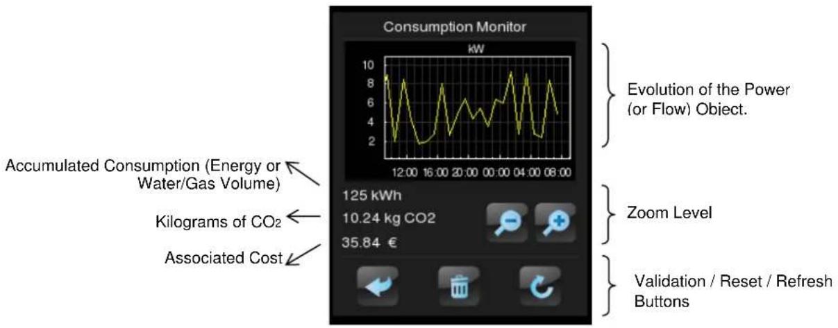
Figure 107 Energy Monitor. Pop-Up Window.
Prior to detailing the elements shown in the pop-up window, the ETS parameters for this type of function are described next:
• Measurement Type: sets whether the values received refer to electric power or water/gas flow. Both are managed analogously; however, the units of measurement and the parameter/object names will differ.
If "Power", specific parameters will show up to set the electric power units (kW or W) and whether the accumulated energy consumption should be shown within the pop-up window (and, if so, the energy measurement units: kWh or Wh).

Figure 108 Energy consumption monitor.
If "Water/Gas", two specific parameters will show up to set the water/gas flow units (litres per hour or m3 por second) and whether the accumulated volume should be shown within the pop-up window (in such case, the volume units will be m3 , as defined by the KNX standard).
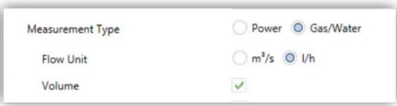
Figure 109 Water/Gas Consumption Monitor.
The electric power or water/gas flow measurement reports should be received, respectively, through objects [Pn][Bi] Consumption Monitor: Power and [Pn][Bi] Consumption Monitor: Flow.
The energy or water/gas volume consumption reports should be received, respectively, through objects [Pn][Bi] Consumption Monitor: Energy and [Pn][Bi] Consumption Monitor: Volume.
CO2: determines whether the pop-up window should show the instant value of the [Energy x] CO2 object or not.
Cost: determines whether the pop-up window should show the instant value of the [Energy x] Cost object or not.
When this function is assigned to the box, two 1-bit communication objects will also be added to the project topology:
[Pn][Bi] Energy Monitor: Request, which will be sent to the bus (value "1") to request the updated value of the measurements. This object must be linked to the analogous object of the external measurement device.
[Pn][Bi] Energy Monitor: Reset, which will be sent to the bus (value "1") to request a value reset to the external measurement device, so the consumption, CO2 and cost variables are re-set to zero. This object must be linked to the analogous object of the external measurement device.
Finally, back to the pop-up window that shows up when the box is pressed, the following elements must be highlighted
• Evolution of the Power/Flow object: shows, as a graph, the chronological evolution of the value of the power or flow object, according to the measurement type. The horizontal axis will show different time lapses (hours, days, or months), depending on the selected zoom level.
- Instant Value of the Energy, CO 2 and Cost objects: indicator that shows the current value of the already mentioned energy / volume, CO 2 and cost objects, provided that the Energy Consumption / Volume, CO2 and Cost checkboxes have been marked.
- Zoom Level: two-button control that lets the user change the time scale, so more / less detail is shown in the graph of the evolution of the power / flow object. The behaviour and the representation of the data are similar to those of the numeric data log (see epigraph 3.6.2.1.5 in section 1).
- Validation / Refresh / Reset buttons: permit, respectively, closing the pop-up window, sending an order to re-set the consumption data (through the already mentioned reset object) and requesting an updated sending of the consumption data (through the request object, already mentioned as well). Note that the Reset button requires a long press to perform this action.
3.6.2.5.4 Daily Timer

Figure 110 Daily Timer
Boxes configured as daily timers let the final user program a timed sending of a value to the bus, being possible to send binary or scene values (according to the parameterisation) at a certain time (either every day or only once) or at the end of a countdown.

Binary value to be sent, or "Scene" icon
Figure 111 Daily Timer (Box)
Hence, when the user presses on the box, a window containing the necessary controls for setting up a timed sending (either at a specific time or after a countdown) will pop up.

Figure 112 Daily Timer (Pop-Up Window)
This window contains the following elements:
Timer Type: two-button selector to step through the following options:
 |  |  | [HA0X] |
| Timer inactive. | Timer active (every day). | Timer active (no repetition). | Timer active (countdown). |
• Time Selector: depending on the selected timer type, permits setting the time for the automated sending, or the length of the countdown.
Value to be Sent: in case of having parameterised the sending of a binary value, this control lets the user determine the concrete value to be sent ("OFF" or "ON"). In the case of the sending of a scene, this control is not shown, as the scene number is set by parameter.
Hence, at the time set by the user or once the countdown ends, the bus will be automatically sent the corresponding value, through the [Pn][Bi] Daily Timer Control object (for binary values) or through the [General] Scenes: Send object (in case of scene values). In both cases the [Pn][Bi] Daily Timer Enabling binary object will be available, making it possible to disable (by sending the value "0") or to enable (value "1") the execution of the timed sending set by the user. By default, timed sending is always enabled.
Note: in case of disabling a sending through [Pn][Bi] Daily Timer Enabling, the corresponding box will show the "forbidden" icon, although the box will not lose the configuration previously set by the user.
Finally, this function offers the following parameters in ETS:
Timer Type: switches between "1-bit value" (default option) and "Scene".
- Scene Number: shown only after selecting "Scene" for the above parameter. This field defines the number of the scene (1-64) that will be sent to the bus on the execution of the timed sending.
- Enablement: sets the value to enable and disable the timer through the object [Pn][Bi] Daily Timer Enabling. The options are "0=Disable; 1=Enable" (default option) "0=Enable; 1=Disable".
3.6.2.5.5 Weekly Timer
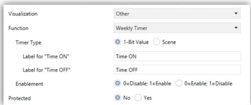
Figure 113 Weekly Timer
Boxes configured as weekly timers let the final user program a timed sending of a binary or scene value to the bus (according to the parameterisation) at a certain time on certain days (on a weekly basis).
The difference between the daily and the weekly timers is that the latter does not permit the countdown-based sending, although it does permit that a time-based sending takes place every week, on the days selected by the user.

Figure 114 Weekly Timer (Box).
Hence, when the user presses on the box, a window similar to Figure 115 will pop up.

Figure 115 Weekly Timer (Pop-Up Window).
This window contains the following elements:
Day Selector: lets the user select the days the timed sending will take place on. The first day of the week depends on the parameterisation of the Calendar tab (see section 3.2.7).
Value to be Sent (ON / OFF): lets the user set the value to be sent. It can be "ON" or "OFF", or even both at different times. One time selector is provided for each of the two values.
Note: if instead of the sending of a binary value, the sending of a scene value has been parameterised, only one checkbox and one time selector will be shown, so the user can enable/disable the sending of the scene value and, if enabled, set the desired time.
• Time Selector: let the user set the time at which the automatic sending will take place.
Hence, at the specified time on the days selected by the user, the bus will be automatically sent the corresponding value through the [Pn][Bi] Weekly Timer Control object (in the case of sending a binary value) or through the [General] Scenes: Send object (in the case of sending a scene number).
In both cases the [Pn][Bi] Weekly Timer Enabling binary object will be available, making it possible to disable (by sending the value "0") or to enable (value "1") the execution of the timings set by the user. By default, user timings are always enabled.
Note: in case of disabling a sending through [Pn][Bi] Weekly Timer Enabling, the corresponding box will show the "forbidden" icon, although the box will not lose the configuration previously set by the user.
Finally, this function offers the following parameters in ETS:
Timer Type: switches between "1-bit value" (default option) and "Scene".
- Scene Number: shown only after selecting "Scene" for the above parameter. This field defines the number of the scene (1-64) that will be sent to the bus on the execution of the timed sending.
- Label for "Time ON": permits customising the label shown next to the checkbox that enables/disables the sending of the switch-on order. The default value is "Time ON".
- Label for "Time OFF": permits customising the label shown next to the checkbox that enables/disables the sending of the switch-off order. The default value is "Time OFF".
- Label for "Scene": permits customising the label shown next to the checkbox that enables/disables the scene sending. The default value is "Scene".
- Enablement: sets the value to enable and disable the timer through the object [Pn][Bi] Daily Timer Enabling. The options are "0=Disable; 1=Enable" (default option) "0=Enable; 1=Disable".
Note: the execution of user-defined timers is triggered on the detection of state transitions, even if the clock does not specifically pass through the specified time. In other words, supposing one timed sending of the value "ON" at 10:00h am and one timed sending of the value "OFF" at 8:00h pm, if the internal clock is set to 9:00h pm just after 10:00h am (and therefore after having sent the value "ON"), then the "OFF" order corresponding to 8:00h pm will take place immediately after the time change.
3.6.2.5.6 Chrono-thermostat
Boxes configured as chrono-thermostats let the final user schedule the timed sending of temperature setpoint orders (preceded by switch-on orders) or switch-off orders to a thermostat through the KNX bus.
To that end, it is necessary to configure the following two parameters:

Figure 116 Chrono-thermostat
• Minimum Setpoint Value: minimum setpoint value the user will be able to set.
Range: [-20, 95] x 1°C. Default value: 18°C.
• Maximum Setpoint Value: maximum setpoint value the user will be able to set. Range: [-20, 95] x 1°C. Default value: 30°C.
- Enablement: sets the value to enable and disable the chrono-thermostat through the object [Pn][Bi] Daily Timer Enabling. The options are "0=Disable; 1=Enable" (default option) "0=Enable; 1=Disable".
When a box is configured as a chrono-thermostat, it looks as follows:

Figure 117 Chrono-thermostat (box)
The switch button on the left activates / deactivates the chrono-thermostat, that is, resumes or stops the execution of the timed actions that may have been configured (the configuration is not lost during the deactivation). While the chrono-thermostat is not active, icon ☑ is shown next to the switch button.
On the other hand, when the user touches on the calendar icon, a new window will pop up to let the user set the actions to be executed:

Figure 118 Chrono-thermostat (pop up)
Each box configured as a chrono-thermostat contains four pages with six customisable timers each, being possible for the user to configure up to 24 timed actions.
The buttons on the bottom of the window let switching across the four pages, as well as closing the pop-up window (button 1).
For each of the six timed actions of each page it is necessary to select, on the first hand, the days of the week on which the action should be performed, as well as the specific time of day (the first day of the week will depend on the parameterisation of the Calendar tab; see section 3.2.7).
After that, the user should select (through controls ⚠️ and ⚠️) the temperature setpoint that will be sent. The range of this value is restricted by parameters “Minimum Setpoint Value” and “Maximum Setpoint Value”.
Note: the timed sending of a temperature setpoint is always preceded by a switch-on order.
Instead of a temperature setpoint, it is also possible to send a switch-off order to the thermostat. In such case, the user must successively press on the above control until one of the range limits is reached, after which the word "OFF" will show on the screen instead of a temperature value.
On the other hand, it is possible to activate or deactivate each action separately by marking its corresponding checkbox. While this checkbox remains unmarked, the action configured will not take place.
On power failures and ETS downloads, chrono-thermostat boxes behave as detailed in section 3.8.
Each chrono-thermostat box entails the following three objects:
• “[Pn][Bi] Chrono-thermostat: Enabling”: permits activating (value “1”) or deactivating (value “0”) the chrono-thermostat analogously as from the on-screen switch button of the box, which will show the icon ☑ while deactivated.
• “[Pn][Bi] Chrono-thermostat: Temperature Setpoint”: this is the object through which the timed temperature setpoints will be sent.
• “[Pn][Bi] Chrono-Thermostat: On/Off”: this is the object through which the timed switch-off orders will be sent.
3.6.2.5.7 Alarm
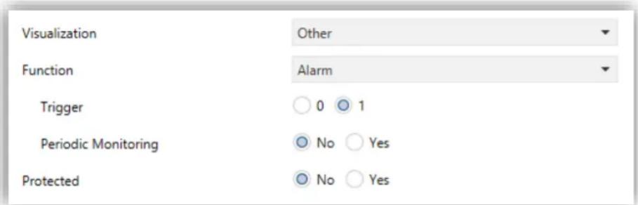
Figure 119 Alarm
Boxes configured as alarms perform user warnings on anomalous events. For this purpose, boxes of this type are related to a binary object ([Pn][Bi] Alarm Trigger) that permits receiving alarm messages from the bus, thus making Z41 Pro / Lite / COM emit a continuous beep while the screen light blinks. In addition, the screen will automatically browse to the page containing the alarm box that has been triggered. After that moment, pressing on the "Menu" button will interrupt the beeps and blinks although the box will still show an intermitting icon, which means that the alarm is still active and unconfirmed. Additionally, the icon of the page that contains the box will also show an exclamation.

Figure 120 Alarm (Box).
The intermitting exclamation means that the alarm is active and unconfirmed.
However, alarm boxes implement an additional binary object, [Pn][Bi] Alarm Confirmation, intended for receiving the value "1" from the bus, which will be interpreted as an acknowledgement of the alarm, thus making the icon intermittence stop. Alternatively, the alarm can be acknowledged (and muted) by touching on the "OK" button in the box itself, which will cause the sending of the value "1" through the mentioned object.
The alarm will definitely become inactive once it has been confirmed and, in addition, once the [Pn][Bi] Alarm Trigger object goes back to the “no alarm” state (the order of these two events is irrelevant), after which the icon will finally turn off.
![graph TD A["No Alarm"] -->|Trigger| B["Alarm"] B -->|Random Button Press| C["Alarm Muted"] C -->|Acknowledgmt.| D["Alarm Confirmed"] D -->|Not(Trigger)| A](/content/2026/07/1421749/images/9f60436febe9b8749ad50552005bdcc2fbc31a7ac45e7e0b00ef41927fd325d8.jpg)
Figure 121 Alarm state diagram (case of confirmation previous to the alarm end)
There is also the possibility of periodically monitoring the status of the trigger object, for situations where this object is periodically received from the bus. This will let Z41 Pro / Lite / COM automatically assume the alarm situation if the “no alarm” value does not get sent through the trigger object after a certain time, for example upon failures of the transmitter. The maximum time window can be defined by parameter.
Consequently, alarm boxes permit configuring the following parameters:
Trigger: defines the value that will trigger the alarm ("0" or "1"; it is "1" by default), i.e., the value that, when received through [Pn][Bi] Alarm Trigger, should be interpreted by Z41 Pro / Lite / COM as an alarm situation. Implicitly, this parameter also defines the inverse "no alarm" value.
Periodic Monitoring: activates ("Yes") or deactivates ("No", default option) periodic monitoring of the alarm trigger object.
Cycle Time (x 1min.): in case of having selected "Yes" under the above parameter, sets the maximum accepted time space without receiving the "no alarm" value before Z41 Pro / Lite / COM adopts the alarm situation.
Example I: supposing a certain sensor responsible for sending the value “1” (once) to the bus when a flood is detected, and the value “0” (again, only once) when such situation terminates, if the object sent is linked to the alarm trigger object from an alarm box in Z41 Pro / Lite / COM where no periodical monitoring has been parameterised and where the value “1” has been set as the alarm value, then Z41 Pro / Lite / COM will notify an emergency every time a flood takes place. The notification will stop as soon as the user touches any button, although a warning icon will still blink on the screen. After that, if the user acknowledges the alarm, the icon will stop blinking; switching then off once the sensor sends a “0”.
Example II: suppose a certain CO2 sensor responsible for sending the value “0” to the bus every two minutes, except when it detects a dangerous CO2 level; in such case, it will immediately send the value “1”. If the object being sent is linked to the alarm trigger object from an alarm box in Z41 Pro / Lite / COM where periodic monitoring has been parameterised and where the value “1” is configured as the alarm trigger value, then Z41 Pro / Lite / COM will notify the user about the emergency both if the CO2 level reaches a dangerous level and if the sensor stops sending the value “0”, for example due to failures or sabotage. The user should proceed in the same manner as in the above example to manage the alarm notification.
3.6.2.5.8 Holiday Calendar

Figure 122 Holiday Calendar
Boxes configured as a Holiday Calendar let the end user set a number of holidays on a calendar, and to program the sending of one value or another when the date changes, depending on whether the new date is a weekday or not.
It is necessary to configure the following parameters:
- Send 1-bit Object: always-enabled parameter to make it evident that on a date change, the device will always send a 1-bit object to indicate whether the new day is a weekday or a holiday.
Value: values that will be sent through the 1-bit object depending on whether the day is a weekday or a holiday. Options: "0 = Weekday; 1 = Holiday" (default option) and "1 = Weekday; 0 = Holiday". - Send Scene: checkbox to enable or disable a scene sending on date changes. When enabled, two more parameters will show:
➢ Scene Number (Workday): number of the scene (between 1 and 64) that will be sent to the bus if the new day is a workday. If set to 0, no values will be sent.
➢ Scene Number (Holiday): number of the scene (between 1 and 64) that will be sent to the bus if the new day is a holiday. If set to 0, no values will be sent.

Figure 123 Send Scene
Send 1-byte Object: checkbox to enable or disable the sending of a 1-byte object (0 to 255) on date changes. When enabled, two more parameters will show:
Value (Workday): number of the scene (between 0 and 255) that will be sent to the bus if the new day is a workday.
Value (Holiday): value (between 0 and 255) that will be sent to the bus if the new day is a holiday.

Figure 124 Send 1-byte Object.
- Sending Frequency: defines when the 1-bit, 1-byte and scene objects should be sent. Options: "Everyday" (default) and "Only on Transitions" (i.e., only when the new day is a different type).
- Button Icon: permits selecting the icon of the button that provides access to the calendar.
Note: a list with all icons available can be found in document "Z41 Icon list", available at www.zennio.com.
Boxes of this type look similar to the following figure:

Figure 125 Holiday Calendar (box).
When the user presses on the calendar button, a new window will pop up to let them set the holidays by simply tapping on the calendar – days marked as holidays will remain highlighted in orange colour (all days are considered workdays by default).

Figure 126 Holiday Calendar.
Note: this configuration is year-dependent. Therefore, the holiday selection only applies to the year shown on the calendar, although it is possible to navigate to the subsequent years in order to set the corresponding holidays in advance.
The buttons on the upper section of the pop-up window let the user browse through the months of the year, while the button on the bottom ( ) lets leaving the pop-up window.
On the change of day, the device considers the previous date and the new one, and determines their types (workday or holiday). Depending on the sending frequency configured, the corresponding one-bit, one-byte or scene objects (which are not exclusive of each other) will be sent or not.
3.6.2.5.9 Macro
Macros let the end user configure and execute a set of sequential actions, which will consist in actions from other boxes. A delay between them can also be configured.
This function allows defining scenes manually from the on-screen menu.
To configure a box as a macro control, the following parameters must be set:

Figure 127 Macro
Trigger Object: sets the type of the object that will trigger the execution of the macro upon the reception of the proper value. If set to "1-Bit Object", an object with name "[Pn][Bi] Macro: trigger" will be incorporated to the project topology. On the contrary, if set to "Scene Object", the trigger value will be expected through the "[General] Scenes: Receive" object.
Value: "0=Stop; 1=Start" or "0=Start; 1=Stop" (in the case of the one-bit object) or two integer values in the range 1-64, one for triggering the execution and another one to stop it (in the case of the scene object).
- Send Object When Macro Starts: sets whether the device should send a value to the bus upon the execution of the macro. The options are: "Disabled", "1-Bit Object" (in which case the value will be sent through "[Pn][Bi] Macro: Started") or "Scene Object" (in which case the value will be sent through "[General] Scenes: Send").
Value: sets the value to be sent, either "0", "1" or an integer value in the range 1-64, depending on the above parameter.
A box configured as a Macro will be composed of two buttons, as shown in the Figure 128.

Figure 128 Macro (box)
Left button: runs / stops the execution of the macro.
Right button: opens up the macro configuration panel 2 (Figure 129).

Figure 129 Macro Pop-Up
The centre of the panel shows the list of actions that make up the macro. The ↑ and ↓ arrows allow stepping through these actions, while a long press on the garbage icon allows removing the selected action. On the other hand, the ← and → arrows should be used to set the desired delay of the action, while the “+” icon allows inserting additional actions. The page, box and value corresponding to each of the actions in the list can be set through the upper section of the panel.
Up to 30 actions are available per macro.
Note: A Macro box can only be configured with actions set in boxes such as 1-button Control, 2-button Control, Climate Control, RGB/RGBW, Macro (as long as it is not the
macro itself) or Logic function with a security level equal to or less than the macro box itself. Boxes configured as indicators or actions that are not compatible with macros will not appear in the action selector of the macro dialog.
3.6.2.5.10 Scheduler
Schedulers allow the execution of time-controlled actions of other boxes.
To configure a box as a scheduler control, the following parameters must be set:
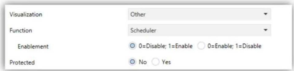
Figure 130 Scheduler
- Enablement: sets the value to enable and disable the sending of actions of the scheduler through the object “[Pn][Bi] Scheduler Enabling”. The options are: “0=Disable; 1=Enable” or “0=Enable; 1=Disable”.
A box configured as a Scheduler will have the same appearance as a Chrono-Thermostat, as shown in Figure 131, and will be composed of two buttons and an indicator.

Figure 131 Scheduler (box)
Left Button: enables or disables the Scheduler.
Right Button: opens up the macro configuration panel 3 (Figure 132).
Indicator: nothing (enabled) or ⏱ (disabled).
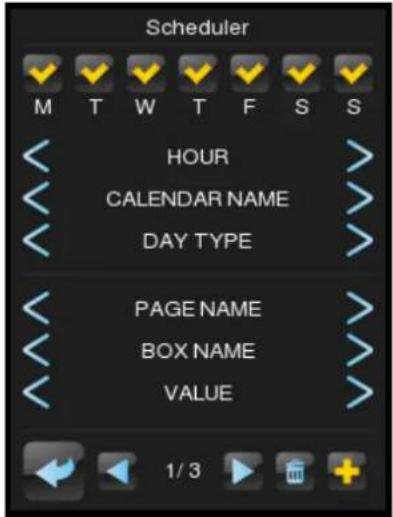
Figure 132 Scheduler
In the upper section of the panel can be configured the day of the week and the hour of the execution of the action. Moreover, if there is any calendar configured (see section 3.6.2.5.8 above) it is possible to set if the action is executed in holidays or in workdays (or both if no calendar is selected). The page, box and value corresponding to the actions can be set through the central section of the panel. The “+” icon allows inserting additional actions. The ← and → arrows allow stepping through the time-controlled actions, while a long press on the garbage icon allows removing the action
Up to 30 time-controlled actions are available per scheduler.
Note: A Scheduler box can only be configured with actions set in boxes such as 1-button Control, 2-button Control, Climate Control, RGB/RGBW, Macro (as long as it is not the macro itself) or Logic function with a security level equal to or less than the scheduler box itself. Boxes configured as indicators or actions that are not compatible will not appear in the action selector of the scheduler dialog.
3.6.2.5.11 Logic Function
A logical function allows the execution of the action any other box when certain conditions are fulfilled.
To configure a box as a Logic Function control, the following parameters must be set:
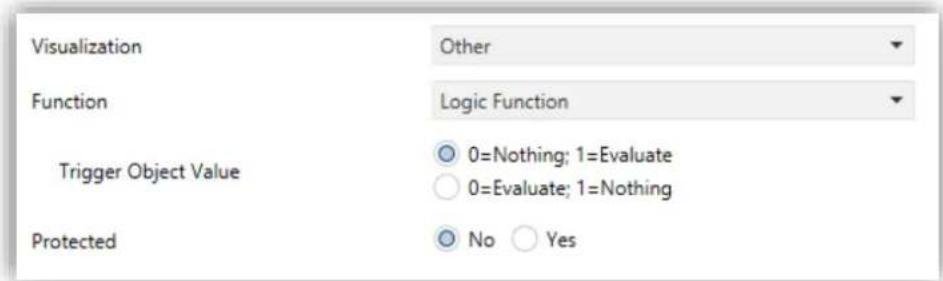
Figure 133 Logic Function
- Trigger Object Value: sets the value that triggers the execution of the logic function when received through the object “[Pn][Bi] Logical Function: Trigger”. The options are: “0=Nothing; 1=Evaluate” or “0=Evaluate; 1=Nothing”
A box configured as a logical function will be displayed as shown in Figure 134, and will be composed of two buttons without indicator.

Figure 134 Logic Function (box)
Left Button: starts the execution of the logical function.
Right Button: opens up the logical function configuration panel 4 (Figure 135).
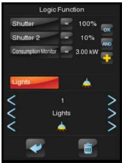
Figure 135 Logic Function
In the upper section of the panel can be configured the restrictions. The “+” icon allows inserting additional restrictions. In the central section of the panel the action to execute can be configured. The page, box and value corresponding to the selected item (either a restriction or an action) are set at the bottom of the display. A long pulse on the trash icon will remove whole configuration.
Up to 4 restrictions and one action per box are available.
Note: A Logic Function box can only be configured with actions set in boxes such as 1-button Control, 2-button Control (Enumerated, Numeric, Shutter Control or Dimming Control), Climate Control, Consumption Monitor or RGB/RGBW with a security level equal to or less than the logic function box itself. Boxes configured as indicators or actions that are not compatible will not appear in the action selector of the logic function dialog.
3.6.2.5.12 Page Direct Link
It is a shortcut to the page indicated by parameter.
To configure a box as a Logic Function control, the following parameters must be set:
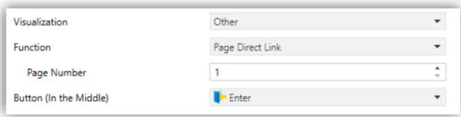
Figure 136 Page Direct Link
Page Number: 1 (by default) to 12.
Button (In the Middle): permits selecting the icon of the button.
Note: a list with all icons available can be found in document "Z41 Icon list", available at www.zennio.com.
The default aspect of a Page Direct Link box is show in Figure 137, but the icon and the text are also configurable:
Figure 137 Page Direct Link (box)
3.6.2.5.13 Video Intercom (Z41 COM)
Permits accessing to the call log of a video intercom and, if the video intercom type is private (see section 3.3), accessing to the visualization of the images from the camera of the outdoor unit (GetFace IP).


Figure 138 Video Intercom (box).
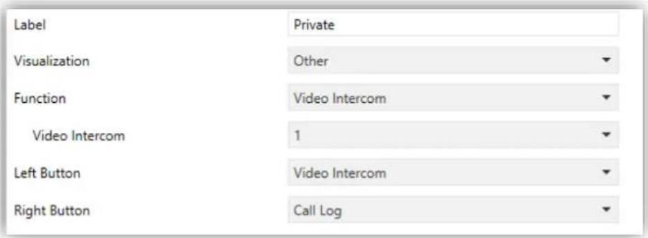
Figure 139 Video Intercom
To configure a box as a Video Intercom, the following parameters must be set:
Video Intercom: number of the VI to which the box is associated.
Note: A warning message will be shown in case that the video intercom selected is not enabled.
- Left Button / Right Button: dropdown list for the selection of the icons to be displayed inside the buttons in the box.
3.6.2.5.14 Internal Call (Z41 COM)
Permits calling to any of the configured contacts or those imported via USB.

Figure 140 Internal Call (box).
To configure a box as Internal Call, the following parameters must be set:
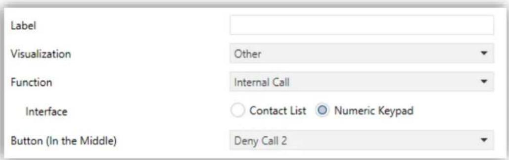
Figure 141 Internal Call parameters.
- Interface: dialog type for internal calls box. This parameter is only available if "Import contacts via USB" has been selected in the general screen of internal calls (see section 3.2.13.2).
Contact List: shows a list of contacts and two arrows to go through it.
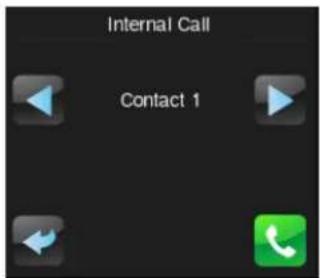
Figure 142 Contact list interface.
Note: This is the interface that will be displayed if the "Import contacts via USB" option is not enabled and the contact list is configured in ETS.
Numeric Keypad: shows a keypad to enter the code number associated with the contact intended to call. This option is suitable for a large number of contacts imported via USB (see section 2.12.2.2.2).

Figure 143 Numeric Keypad.Interface.
The Configuration Page tab contains a set of secondary tabs.
3.7.1 CONFIGURATION
This screen permits the integrator configure the controls that will be available for the final user within the Configuration page (see section 2.3), as well as the label that will identify them on the screen. Note that the Configuration page itself can be activated or hidden from the Configuration screen, under the Menu tab (see section 3.5.1).

Figure 144 Configuration (Configuration Page)
By default, the Time/Date controls and the Device and Profile screens are marked as active. Please refer to section 2.3 for details.
On the other hand, for the Configuration page – as for any other page—, a label (parameter Title), a security level (parameter Protected; see section 3.2.8) can be set, and whether Automatic Page Shaping is required (see section 2.10).
Notes:
The Device Pairing option is only available in Z41 Pro / COM
In Z41 COM there is an additional option VoIP Calls.
3.7.2 DEVICE
If the Device checkbox is marked in Configuration, a new tab named Device will also be shown.
From here it is possible to set the controls that will be accessible from within the Device window:
Programming Button.
Reset.

Figure 145 Device in Z41 Lite and Pro (Configuration Page)
Each of the two controls can be labelled on screen with a custom text (parameter Label).
In Z41 COM, in addition, the indicators listed in the section 3.7.3 can be enabled in this page, as shows the following figure:

Figure 146 Device in Z41 COM (Configuration Page)
Please refer to section 2.3.1 for details.
3.7.3 PROGRAM CONFIGURATION
If the Program Configuration checkbox is marked in Configuration, a new tab named Program Configuration will also be shown.
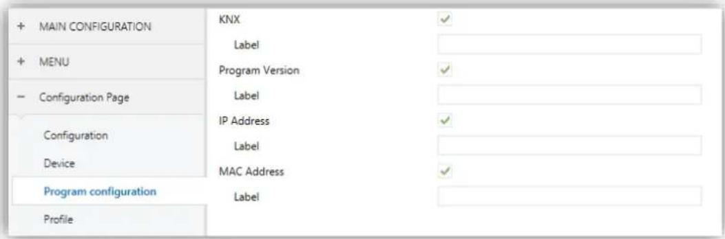
Figure 147 Program Configuration (Configuration Page)
From here it is possible to set the indicators that will be included into the Program Configuration window:
KNX (individual address).
Program Version.
In addition, for the Z41 Pro to select two other indicators will also be possible:
IP Address.
MAC Address.
Each indicator can be labelled on screen with a custom text (parameter Label).
Note: In Z41 COM these indicators can be set in the Device tab (see section 3.7.2)
Please refer to section 2.3.2 for details.
3.7.4 PROFILE
If the Profile checkbox is marked in Configuration, a new tab named Profile will also be shown.

Figure 148 Configuration (Profile Page)
From here it is possible to set the controls that will be accessible from within the Profile window:
Brightness,
Melody,
Contrast,
Theme.
Each control can be labelled on screen with a custom text (parameter Label).
Please refer to section 2.3.3 for details.
3.7.5 VoIP CALLS (Z41 COM)
If the VoIP Calls checkbox is marked in Configuration, a new tab with the same name will also be shown.

Figure 149 Configuration (Video Intercom Configuration Page)
From here it is possible to set the controls that will be accessible from within the VoIP Calls configuration window:
Video Intercom Ringtone,
Internal Call Ringtone,
Ringtone Volume,
• “Do Not Disturb” Mode: Enabling,
• “Do Not Disturb” Mode: Timing,
IP Address / Gateway.
Each control can be labelled on screen with a custom text (parameter Label).
Please refer to section 2.3.4 for details.
3.8 THERMOSTAT N

Figure 150 Configuration Screen (Thermostat n)
When functions “Thermostat 1” and “Thermostat 2” from the General screen under the Main configuration tab are enabled, the integrator will be shown two more tabs, both similar to each other, for the parameterisation of these functions independently. Under each of the tabs, a set of screens (Configuration, Setpoint, etc.) is provided to define the type of the thermostatic control the user will be performing from Z41 Pro / Lite / COM.
Note: for further information about the behaviour and the parameterisation of the Zennio "Building" thermostat implemented by Z41 Pro / Lite / COM, please refer to the specific documentation ("Building Thermostat") available at www.zennio.com.
3.9 INPUTS (Z41 PRO AND Z41 LITE)
3.9.1 CONFIGURATION
Z41 Pro / Lite incorporates two analogue/digital inputs, each configurable as a:
Binary Input, for the connection of a pushbutton or a switch/sensor.
• Temperature Probe, to connect a temperature probe.
• Motion Detector, to connect a motion detector from Zennio.
3.9.2 BINARY INPUT
Please refer to the specific user manual "Binary Inputs", available in the Z41 Pro / Lite product section, at the Zennio website (www.zennio.com).
3.9.3 TEMPERATURE PROBE
Please refer to the specific user manual "Temperature Probe", available in the Z41 Pro / Lite product section, at the Zennio website (www.zennio.com).
3.9.4 MOTION DETECTOR
It is possible to connect motion detectors from Zennio to the input ports of Z41 Pro / Lite.
Please refer to the specific user manual "Motion Detector", available in the Z41 Pro / Lite product section, at the Zennio website (www.zennio.com).
3.10 STATUS AFTER PROGRAMMING AND BUS FAILURE
After a power failure (either of KNX bus or auxiliary power), the status of all the controls will be recovered except:
14-byte indicator (see section 3.6.2.1).
• Energy consumption and cost indicators in consumption monitor boxes (see section 3.6.2.5).
On the other hand, after a software update the configuration of the following controls is maintained (while they remain in the same box and page in the new version):
Chronothermostat,
Calendar,
Daily timer and Weekly timer (although need to be enabled again),
Macro,
Scheduler,
Logic function.
RGB and RGBW colour selection history, indicators and consumption monitor logs as well as alarm, error and call logs are also maintained after software updating.
ANNEX I. REMOTE CONTROL VIA IP (Z41 PRO AND Z41 COM)
Z41 Pro and Z41 COM feature an Ethernet interface that makes it possible to perform actions over the device by means of remote IP applications. This brings the option to control its functions analogously as if the device were actually being controlled on site.
CONFIGURING Z41 PRO Z41 PRO / Z41 COM
In order to make the Z41 Pro / Z41 COM control function available for remote applications, it is necessary that the integrator specifically enables it in ETS through the Remote Control through the Internet parameter from the “Ethernet” window, under the “Main Configuration” tab (see section 3.2.11).
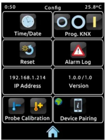
Figure 151 Configuration page with Device Paring enabled.
In addition, before being possible to remotely control Z41 Pro / Z41 COM, it is first necessary to pair it to the remote application. This requires that the integrator also enables the Device Pairing parameter in the “Configuration” window, under the “Configuration Page” tab (see section 2.3). After that, Z41 Pro / Z41 COM will include a new icon into its Configuration page (as in Figure 151), which lets the final user start the pairing process.
The icon of the pairing function contains, on the upper left corner, a service state indicator. This indicator will automatically update if the state changes.
| Indicator | Meaning | |
 | No network connection available. | |
 | No Internet access available. | |
 | Waiting for the Remote Control service. | |
 | Connection and service OK. | |
| [044X] | Remote control in process (remote device currently connected). | |
Table 1 Service States
Note that the decision of disabling back the Device Pairing parameter or not after the pairing process is up to the integrator, depending on whether the final user needs or not to be allowed to pair their Z41 Pro / Z41 COM with further remote applications in the future.
It is also remarkable that disabling this icon is independent from disabling the remote control function itself (preventing further pairing does not block the remote access from previously paired devices), and that the access to this icon will be anyway subject to the security level set for the Configuration page by the integrator (see section 3.2.8).
Note: it is possible to pair multiple Z41 Pro / Z41 COM devices to a particular remote application (or mobile device), as well as pairing a particular Z41 Pro / Z41 COM to multiple remote applications (or mobile devices).
PAIRING PROCEDURE
Once Z41 Pro / Z41 COM has been configured as explained above, pressing on the Device Pairing icon will bring up a pop-up window similar to Figure 152.
The upper section of the pop-up window may display text messages to notify events to the user along the process, while the middle section contains the Pairing Code Request button and an icon with a numeric indicator:

Figure 152 Device Pairing dialog window
- On a short press, the Pairing Code Request button sends a Pairing Code request, which will be responded with an alphanumeric key word that Z41 Pro / Z41 COM will show on the upper section of the window, unless a communication error takes place (in such case, the word "ERROR" will be displayed on the screen). The user will be required to enter this key word on the remote application in order to set the link with Z41 Pro / Z41 COM. The key word will be active for 2 minutes; after that time, it expires and a new one has to be requested again.
Note that this process is only required once, so the mobile device can register the particular Z41 Pro / Z41 COM.
The indicator on the right shows the currently active pairings of the device, that is, the number of remote applications or devices Z41 Pro / Z41 COM remains paired to, and from which it can be controlled. The initial value is 0.
Finally, the lower portion of the window comprises the validation button, which lets the user confirm the process and close the pop-up window, and the bin button, which (after a long press) deletes all current pairings and clears the pairing counter.
'PUSH' NOTIFICATIONS
Z41 Pro / Z41 COM incorporates the “push” notification function, which consists in notifying the mobile devices (no matter if the remote control application has been started or not) about alarm events (see section 3.6.2.5):
- Alarm activation: a box that has been assigned the Alarm function has either received the alarm trigger value from the KNX bus, or exceeded the cyclical monitoring period.
- Alarm confirmation: a box with an active alarm has been acknowledged by the user.
- Alarm deactivation: a box that has already been acknowledged by the user has also received the no-alarm trigger value. Therefore, the alarm has been deactivated and acknowledged.
The above notifications are shown on the mobile device (unless “push” notifications are disabled by the operating system of the device, depending on the user settings) through messages similar to the following figure, and according to the label assigned to the involved alarm box:

Figure 153 Push Notification
Notes:
In case of network unavailability, Z41 Pro / Z41 COM will queue all notifications related to the alarm events that may take place and will send them as soon as the network is available.
- Queued (unsent) notifications are discarded on external power failures, but not on KNX bus power failures.
• In the unlikely event of a very long network failure, the queue may become out of space, and therefore further notifications will not be queued.
Zennio Avance y Tecnología S.L. does not accept any responsibility for losses of "push" messages due to network, hardware or software failures of any kind.
REMOTE APPLICATIONS
For instructions on configuring and using the available remote applications, please refer to the "Zennio Remote" specific document, available at the Zennio home site: http://www.zennio.com.
ANNEX II. COMMUNICATION OBJECTS OF Z41 LITE AND Z41 PRO
- "Functional range" shows the values that, with independence of any other values permitted by the bus according to the object size, may be of any use or have a particular meaning because of the specifications or restrictions from both the KNX standard or the application program itself.
| Number | Size | I/O | Flags | Data type (DPT) | Functional Range | Name | Function |
| 1 | 3 Bytes | I/O | C R W T U | DPT_TimeOfDay | 00:00:00 - 23:59:59 | [General] Time | Current Time |
| 2 | 3 Bytes | I/O | C R W T U | DPT_Date | 01/01/1990 - 31/12/2089 | [General] Date | Current Date |
| 3 | 1 Byte | C -- T - | DPT_SceneControl | 0-63; 128-191 | [General] Scenes: Send | Scene Value | |
| 4 | 1 Byte | I | C - W -- | DPT_SceneNumber | 0 - 63 | [General] Scenes: Receive | Scene Value |
| 5 | 2 Bytes | O | C R - T - | DPT_Value_Temp | -273.00° - 670433.28° | [General] Internal Temperature | Current Temperature (Built-in Sensor) |
| 6 | 2 Bytes | I | C - W - U | DPT_Value_Temp | -273.00° - 670433.28° | [General] External Temperature | Temperature to Show in the Display |
| 7 | 1 Byte | I | C - W -- | 1.xxx | 0/1 | [General] Select Language | 0 = Main; 1 = Lang. 2; ... ; 4 = Lang. 5 |
| 8 | 2 Bytes | I | C - W -- | DPT_LanguageCodeAlpha2_ASCII | [General] Select Language | Language selection through ISO 639-1 two letters code | |
| 9 | 1 Bit | I | C - W -- | DPT_Ack | 0/1 | [General] Illumination | 0=No Action; 1=Light Display |
| 10 | 1 Bit | I | C - W -- | DPT_DayNight | 0/1 | [General] Backlight Mode | 0=Normal Mode; 1=Night Mode |
| 1 Bit | I | C - W -- | DPT_DayNight | 0/1 | [General] Backlight Mode | 0=Night Mode; 1=Normal Mode | |
| 11 | 1 Bit | I | C - W -- | DPT_Enable | 0/1 | [General] Touch Lock | 0=Unlocked; 1=Locked |
| 1 Bit | I | C - W -- | DPT_Enable | 0/1 | [General] Touch Lock | 0=Locked; 1=Unlocked | |
| 12 | 1 Bit | O | C R - T - | DPT_Switch | 0/1 | [General] Welcome Object | 1-Bit Generic Control |
| 13, 14, 15, 16, 17 | 1 Bit | I | C - W -- | DPT_Switch | 0/1 | [General] Welcome Object - Additional Condition | Additional Condition Object x |
| 18 | 1 Bit | I | C - W T U | DPT_Switch | 0/1 | [General] Welcome Greeting | 0 = Finish Welcome; 1 = Run Welcome |
| 19 | 14 Bytes | I | C - W -- | DPT_String_UTF-8 | [General] Welcome Greeting - Line x | Text to show on the display at Line 1 | |
| 20 | 14 Bytes | I | C - W -- | DPT_String_UTF-8 | [General] Welcome Greeting - Line x | Text to show on the display at Line 2 | |
| 21 | 14 Bytes | I | C - W -- | DPT_String_UTF-8 | [General] Welcome Greeting - Line x | Text to show on the display at Line 3 |
•Ze41iPro / Lite / COM
| 22 | 14 Bytes | I | C - W - - | DPT_String_UTF-8 | [General] Welcome Greeting - Line x | Text to show on the display at Line 4 | |
| 23 | 1 Bit | I | C - W T U | DPT_Switch | 0/1 | [General] Temperature Scale | 0 = °C; 1 = °F |
| 24 | 1 Byte | I | C - W T - | DPT_Scaling | 0% - 100% | [Profile] Brightness | 0-100% |
| 25 | 1 Byte | I | C - W T - | DPT_Scaling | 0% - 100% | [Profile] Contrast | 0-100% |
| 26 | 1 Byte | I | C - W T - | 1.xxx | 0/1 | [Profile] Melody | 0=Mute; 1=Melody 1; 2=Melody 2; 3=Melody 3 |
| 27 | 1 Byte | I | C - W T - | 1.xxx | 0/1 | [Profile] Theme | 0=Ocean; 1=Sky; 2=Night; 3=Twilight; 4=Egg Shell; 5=Seaside; 6=Rioja; 7=Forest |
| 28, 36, 44, 52, 60, 68, 76, 84, 92, 100, 108, 116, 124, 132, 140, 148, 156, 164, 172, 180, 188, 196, 204, 212, 220, 228, 236, 244, 252, 260, 268, 276, 284, 292, 300, 308, 316, 324, 332, 340, 348, 356, 364, 372, 380, 388, 396, 404, 412, 420, 428, 436, 444, 452, 460, 468, 476, 484, 492, 500, 508, 516, 524, 532, 540, 548, 556, 564, 572, 580, 588, 596, 604, 612, 620, 628, 636, 644, 652, 660, 668, 676, 684, 692, 700, 708, 716, 724, 732, 740, 748, 756, 764, 772, 780, 788 | 1 Bit | I | C - W T U | DPT Switch | 0/1 | [Px][Bx] Binary Indicator | 1-Bit Indicator |
| 1 Byte | I | C - W T U | DPT_Value_1_Ucount | 0 - 255 | [Px][Bx] Enumerated Indicator | 0...255 | |
| 1 Byte | I | C - W T U | DPT_Value_1_Ucount | 0 - 255 | [Px][Bx] 1-Byte Unsigned Int Indicator | 0...255 | |
| 1 Byte | I | C - W T U | DPT_Value_1_Count | -128 - 127 | [Px][Bx] 1-Byte Signed Int Indicator | -128...127 | |
| 1 Byte | I | C - W T U | DPT_Scaling | 0% - 100% | [Px][Bx] Percentage Indicator | 0-100% | |
| 2 Bytes | I | C - W T U | DPT_Value_2_Ucount | 0 - 65535 | [Px][Bx] 2-Byte Unsigned Int Indicator | 0...65535 | |
| 2 Bytes | I | C - W T U | DPT_Value_2_Count | -32768 - 32767 | [Px][Bx] 2-Byte Signed Int Indicator | -32768...32767 | |
| 2 Bytes | I | C - W T U | 9.xxx | -671088.64 - 670433.28 | [Px][Bx] 2-Byte Float Indicator | -671088.64...670433.28 | |
| 1 Byte | I | C - W T U | DPT_Scaling | 0% - 100% | [Px][Bx] Shutter Position | 0%=Top; 100%=Bottom | |
| 1 Byte | I | C - W T U | DPT_Scaling | 0% - 100% | [Px][Bx] Light Indicator | 0%=Off; 100%=On | |
| 2 Bytes | I | C - W T U | DPT_Value_Temp | -273.00° - 670433.28° | [Px][Bx] Temperature Indicator | Absolute Float Value | |
| 1 Bit | I | C - W T U | DPT_Heat_Cool | 0/1 | [Px][Bx] Mode Indicator | 0 = Cool; 1 = Heat | |
| 1 Byte | I | C - W T U | DPT_HVACContrMode | 0=Auto1=Heat3=Cool9=Fan14=Dry | [Px][Bx] Mode Indicator | Heat, Cool, Auto, Fan and Dry | |
| 1 Byte | I | C - W T U | DPT_HVACMode | 1=Comfort2=Standby3=Economy4=Building Protection | [Px][Bx] Special Mode Indicator | Comfort, Standby, Economy, Building Protection and Auto | |
| 1 Byte | I/O | CRWTU | DPT_Scaling | 0% - 100% | [Px][Bx] Red Channel | 0-100% | |
| 1 Bit | I | C - W - U | DPT_Alarm | 0/1 | [Px][Bx] Alarm Trigger | Trigger |
•Ze41iPro / Lite / COM
| 1 Bit | I | C - W T U | DPT_Enable | 0/1 | [Px][Bx] Weekly Timer Enabling | 0 = Disabled; 1 = Enabled | |
| 1 Bit | I | C - W T U | DPT_Enable | 0/1 | [Px][Bx] Daily Timer Enabling | 0 = Disabled; 1 = Enabled | |
| 3 Bytes | I/O | C R W T U | DPT_Colour_RGB | [0 - 255] * 3 | [Px][Bx] RGB Color | Red, Green and Blue Components | |
| 1 Bit | I | C - W T U | DPT_Enable | 0/1 | [Px][Bx] Chrono-thermostat: Enabling | 0 = Disabled; 1 = Enabled | |
| 4 Bytes | I | C - W T U | DPT_Value_Power | [Px][Bx] Consumption Monitor: Power | W | ||
| 2 Bytes | I | C - W T U | DPT_Power | -671088.64 - 670433.28 kW | [Px][Bx] Consumption Monitor: Power | kW | |
| 4 Bytes | I | C - W T U | DPT_Value_Volume_Flux | [Px][Bx] Consumption Monitor: Flow | m3/s | ||
| 2 Bytes | I | C - W T U | DPT_Value_Volume_Flow | [Px][Bx] Consumption Monitor: Flow | l/h | ||
| 4 Bytes | I | C - W T U | 14.xxx | [Px][Bx] 4-Byte Float Indicator | -3.403E+38...3.403E+38 | ||
| 4 Bytes | I | C - W T U | DPT_Value_4_Count | -2147483648 - 2147483647 | [Px][Bx] 4-Byte Signed Int Indicator | -2147483648...2147483647 | |
| 1 Byte | I | C - W T U | DPT_Scaling | 0% - 100% | [Px][Bx] Fan Indicator | 0 - 100% | |
| 1 Byte | I | C - W T U | DPT_Value_1_Ucount | 0 - 255 | [Px][Bx] Fan Indicator | Enumerated Value | |
| 1 Bit | I | C - W - U | DPT_Switch | 0/1 | [Px][Bx] Macro: Trigger | 0 = Start; 1 = Stop | |
| 1 Bit | I | C - W - U | DPT_Switch | 0/1 | [Px][Bx] Macro: Trigger | 0 = Stop; 1 = Start | |
| 1 Bit | I | C - W T U | DPT_Enable | 0/1 | [Px][Bx] Scheduler Enabling | 0 = Disabled; 1 = Enabled | |
| 1 Bit | I | C - W - U | DPT_Ack | 0/1 | [Px][Bx] Logic Function: Trigger | 0 = Nothing; 1 = Evaluate | |
| 1 Bit | I | C - W - U | DPT_Ack | 0/1 | [Px][Bx] Logic Function: Trigger | 0 = Evaluate; 1 = Nothing | |
| 1 Bit | I | C - W T U | DPT_Enable | 0/1 | [Px][Bx] Daily Timer Enabling | 0 = Enabled; 1 = Disabled | |
| 1 Bit | I | C - W T U | DPT_Enable | 0/1 | [Px][Bx] Chrono-thermostat: Enabling | 0 = Enabled; 1 = Disabled | |
| 1 Bit | I | C - W T U | DPT_Enable | 0/1 | [Px][Bx] Weekly Timer Enabling | 0 = Enabled; 1 = Disabled | |
| 1 Bit | I | C - W T U | DPT_Enable | 0/1 | [Px][Bx] Scheduler Enabling | 0 = Enabled; 1 = Disabled | |
| 29, 37, 45, 53, 61, 69, 77, 85, 93, 101, 109, 117, 125, 133, 141, 149, 157, 165, 173, 181, 189, 197, 205, 213, 221, 229, 237, 245, 253, 261, 269, 277, 285, 293, 301, 309, 317, 325, 333, 341, 349, 357, 365, 373, | 1 Bit | O | CR - T - | DPT_Switch | 0/1 | [Px][Bx] Binary Control | 1-Bit Control |
| 1 Byte | O | CR - T - | DPT_Value_1_Ucount | 0 - 255 | [Px][Bx] 1-Byte Unsigned Int Control | 0...255 | |
| 1 Byte | O | CR - T - | DPT_Value_1_Count | -128 - 127 | [Px][Bx] 1-Byte Signed Int Control | -128...127 | |
| 1 Byte | O | CR - T - | DPT_Scaling | 0% - 100% | [Px][Bx] Percentage Control | 0-100% |
•Ze41iPro / Lite / COM
| 381, 389, 397, 405, 413, 421, 429, 437, 445, 453, 461, 469, 477, 485, 493, 501, 509, 517, 525, 533, 541, 549, 557, 565, 573, 581, 589, 597, 605, 613, 621, 629, 637, 645, 653, 661, 669, 677, 685, 693, 701, 709, 717, 725, 733, 741, 749, 757, 765, 773, 781, 789 | 2 Bytes | O | CR-T- | DPT_Value_2_Ucount | 0 - 65535 | [Px][Bx] 2-Byte Unsigned Int Control | 0...65535 |
| 2 Bytes | O | CR-T- | DPT_Value_2_Count | -32768 - 32767 | [Px][Bx] 2-Byte Signed Int Control | -32768...32767 | |
| 2 Bytes | O | CR-T- | 9.xxx | -671088.64 - 670433.28 | [Px][Bx] 2-Byte Float Control | -671088.64...670433.28 | |
| 1 Byte | O | CR-T- | DPT_Value_1_Ucount | 0 - 255 | [Px][Bx] Enumerated Control | 0...255 | |
| 1 Bit | O | CR-T- | DPTUpDown | 0/1 | [Px][Bx] Move Shutter | 0=Up; 1=Down | |
| 1 Bit | O | CR-T- | DPT_Switch | 0/1 | [Px][Bx] Light On/Off | 0=Off; 1=On | |
| 2 Bytes | O | CR-T- | DPT_Value_Temp | -273.00° - 670433.28° | [Px][Bx] Temperature Control | Absolute Float Value | |
| 2 Bytes | I/O | CR_WT- | DPT_Value_Tempd | -671088.64° - 670433.28° | [Px][Bx] Temperature Offset Control | Relative Float Value | |
| 1 Bit | O | CR-T- | DPT_Step | 0/1 | [Px][Bx] Temperature Offset Control | 0=Decrease; 1=Increase | |
| 1 Bit | O | CR-T- | DPT_Heat_Cool | 0/1 | [Px][Bx] Mode Control | 0=Cool; 1=Heat | |
| 1 Byte | O | CR-T- | DPT_HVACContrMode | 0=Auto1=Heat3=Cool9=Fan14=Dry | [Px][Bx] Mode Control | Heat, Cool, Auto, Fan and Dry | |
| 1 Byte | O | CR-T- | DPT_HVACMode | 1=Comfort2=Standby3=Economy4=Building Protection | [Px][Bx] Special Mode Control | Comfort, Standby, Economy, Building Protection and Auto | |
| 1 Byte | I/O | CR_WTU | DPT_Scaling | 0% - 100% | [Px][Bx] Green Channel | 0-100% | |
| 1 Bit | O | CR-T- | DPT_Switch | 0/1 | [Px][Bx] Daily Timer Control | 1-Bit Control | |
| 1 Bit | O | CR-T- | DPT_Switch | 0/1 | [Px][Bx] Weekly Timer Control | 1-Bit Control | |
| 1 Bit | I | C-WTU | DPT_Ack | 0/1 | [Px][Bx] Alarm Confirmation | 0=No Action; 1=Confirm | |
| 2 Bytes | O | CR-T- | DPT_Value_Temp | -273.00° - 670433.28° | [Px][Bx] Chrono-thermostat: Temperature Setpoint | Absolute Float Value | |
| 1 Bit | O | CR-T- | DPT_Bool | 0/1 | [Px][Bx] Holiday (1 bit) | 0 = Holiday; 1 = Workday | |
| 1 Bit | O | CR-T- | DPT_Bool | 0/1 | [Px][Bx] Holiday (1 bit) | 0 = Workday; 1 = Holiday | |
| 1 Bit | O | CR-T- | DPT_Step | 0/1 | [Px][Bx] Fan Control (1-Bit) | 0 = Decrease; 1 = Increase | |
| 1 Byte | O | CR-T- | DPT_Scaling | 0% - 100% | [Px][Bx] Fan Control (Scaling) | Auto, 20%, 40%, 60%, 80%, 100% | |
| 1 Byte | O | CR-T- | DPT_Scaling | 0% - 100% | [Px][Bx] Fan Control (Scaling) | Auto, 25%, 50%, 75%, 100% | |
| 1 Byte | O | CR-T- | DPT_Scaling | 0% - 100% | [Px][Bx] Fan Control (Scaling) | Auto, 33%, 67%, 100% | |
| 1 Byte | O | CR-T- | DPT_Scaling | 0% - 100% | [Px][Bx] Fan Control (Scaling) | Auto, 50%, 100% |
•Ze41iPro / Lite / COM
| 1 Byte | O | CR-T- | DPTScaling | 0% - 100% | [Px][Bx] Fan Control (Scaling) | Auto, 100% | |
| 1 Byte | O | CR-T- | DPTScaling | 0% - 100% | [Px][Bx] Fan Control (Scaling) | 0%, 25%, 50%, 75%, 100% | |
| 1 Byte | O | CR-T- | DPTScaling | 0% - 100% | [Px][Bx] Fan Control (Scaling) | 0%, 33%, 67%, 100% | |
| 1 Byte | O | CR-T- | DPTScaling | 0% - 100% | [Px][Bx] Fan Control (Scaling) | 0%, 50%, 100% | |
| 1 Byte | O | CR-T- | DPTScaling | 0% - 100% | [Px][Bx] Fan Control (Scaling) | 0%, 100% | |
| 1 Byte | O | CR-T- | DPTScaling | 0% - 100% | [Px][Bx] Fan Control (Scaling) | 0%, 20%, 40%, 60%, 80%, 100% | |
| 1 Byte | O | CR-T- | DPTScaling | 0% - 100% | [Px][Bx] Fan Control (Scaling) | 20%, 40%, 60%, 80%, 100% | |
| 1 Byte | O | CR-T- | DPTScaling | 0% - 100% | [Px][Bx] Fan Control (Scaling) | 25%, 50%, 75%, 100% | |
| 1 Byte | O | CR-T- | DPTScaling | 0% - 100% | [Px][Bx] Fan Control (Scaling) | 33%, 67%, 100% | |
| 1 Byte | O | CR-T- | DPTScaling | 0% - 100% | [Px][Bx] Fan Control (Scaling) | 50%, 100% | |
| 1 Byte | O | CR-T- | DPTScaling | 0% - 100% | [Px][Bx] Fan Control (Scaling) | 100% | |
| 1 Byte | O | CR-T- | DPT_Value_1_Ucount | 0 - 255 | [Px][Bx] Fan Control (Enumerated) | Auto, 1, 2, 3, 4, 5 | |
| 1 Byte | O | CR-T- | DPT_Value_1_Ucount | 0 - 255 | [Px][Bx] Fan Control (Enumerated) | Auto, 1, 2, 3, 4 | |
| 1 Byte | O | CR-T- | DPT_Value_1_Ucount | 0 - 255 | [Px][Bx] Fan Control (Enumerated) | Auto, 1, 2, 3 | |
| 1 Byte | O | CR-T- | DPT_Value_1_Ucount | 0 - 255 | [Px][Bx] Fan Control (Enumerated) | Auto, 1, 2 | |
| 1 Byte | O | CR-T- | DPT_Value_1_Ucount | 0 - 255 | [Px][Bx] Fan Control (Enumerated) | Auto, 1 | |
| 1 Byte | O | CR-T- | DPT_Value_1_Ucount | 0 - 255 | [Px][Bx] Fan Control (Enumerated) | 0, 1, 2, 3, 4, 5 | |
| 1 Byte | O | CR-T- | DPT_Value_1_Ucount | 0 - 255 | [Px][Bx] Fan Control (Enumerated) | 0, 1, 2, 3, 4 | |
| 1 Byte | O | CR-T- | DPT_Value_1_Ucount | 0 - 255 | [Px][Bx] Fan Control (Enumerated) | 0, 1, 2, 3 | |
| 1 Byte | O | CR-T- | DPT_Value_1_Ucount | 0 - 255 | [Px][Bx] Fan Control (Enumerated) | 0, 1, 2 | |
| 1 Byte | O | CR-T- | DPT_Value_1_Ucount | 0 - 255 | [Px][Bx] Fan Control (Enumerated) | 0, 1 |
•Ze41iPro / Lite / COM
| 1 Byte | O | CR-T- | DPT_Value_1_Ucount | 0 - 255 | [Px][Bx] Fan Control (Enumerated) | 1, 2, 3, 4 | |
| 1 Byte | O | CR-T- | DPT_Value_1_Ucount | 0 - 255 | [Px][Bx] Fan Control (Enumerated) | 1, 2, 3 | |
| 1 Byte | O | CR-T- | DPT_Value_1_Ucount | 0 - 255 | [Px][Bx] Fan Control (Enumerated) | 1, 2 | |
| 1 Byte | O | CR-T- | DPT_Value_1_Ucount | 0 - 255 | [Px][Bx] Fan Control (Enumerated) | 1 | |
| 1 Bit | O | CR-T- | DPT_Switch | 0/1 | [Px][Bx] Macro: Started | 0 = Macro Started; 1 = Nothing | |
| 1 Bit | O | CR-T- | DPT_Switch | 0/1 | [Px][Bx] Macro: Started | 0 = Nothing; 1 = Macro Started | |
| 30, 38, 46, 54, 62, 70, 78, 86, 94, 102, 110, 118, 126, 134, 142, 150, 158, 166, 174, 182, 190, 198, 206, 214, 222, 230, 238, 246, 254, 262, 270, 278, 286, 294, 302, 310, 318, 326, 334, 342, 350, 358, 366, 374, 382, 390, 398, 406, 414, 422, 430, 438, 446, 454, 462, 470, 478, 486, 494, 502, 510, 518, 526, 534, 542, 550, 558, 566, 574, 582, 590, 598, 606, 614, 622, 630, 638, 646, 654, 662, 670, 678, 686, 694, 702, 710, 718, 726, 734, 742, 750, 758, 766, 774, 782, 790 | 1 Bit | O | CR-T- | DPT_Step | 0/1 | [Px][Bx] Shutter - Stop/Step | 0=Stop/Step Up; 1=Stop/Step Down |
| 30, 31, 38, 39, 46, 47, 54, 55, 62, 63, 70, 71, 78, 79, 86, 87, 94, 95, 102, 103, 110, 111, 118, 119, 126, 127, 134, 135, 142, 143, 150, 151, 158, 159, 166, 167, 174, 175, 182, 183, 190, 191, 198, 199, 206, 207, 214, 215, 222, 223, 230, 231, 238, 239, 246, 247, 254, 255, 262, 263, 270, 271, 278, 279, 286, 287, 294, 295, 302, 303, 310, 311, 318, 319, 326, 327, 334, 335, 342, 343, 350, 351, 358, 359, 366, 367, 374, 375, 382, 383, 390, 391, 398, 399, 406, 407, 414, 415, 422, 423, 430, 431, 438, 439, 446, 447, 454, 455, 462, 463, 470, 471, 478, 479, 486, 487, 494, 495, 502, 503, 510, 511, 518, 519, 526, 527, 534, 535, 542, 543, 550, 551, 558, 559, 566, 567, 574, 575, 582, 583, 590, 591, 598, 599, 606, 607, 614, 615, 622, 623, 630, 631, | 4 Bit | O | CR-T- | DPT_Control_Dimming | 0x0 (Stop)0x1 (Dec. by 100%)...0x7 (Dec. by 1%)0x8 (Stop)0xD (Inc. by 100%)...0xF (Inc. by 1%) | [Px][Bx] Light Dimming | 4-bit Dimming Control |
•Ze41iPro / Lite / COM
| 638, 639, 646, 647, 654, 655, 662, 663, 670, 671, 678, 679, 686, 687, 694, 695, 702, 703, 710, 711, 718, 719, 726, 727, 734, 735, 742, 743, 750, 751, 758, 759, 766, 767, 774, 775, 782, 783, 790, 791 | |||||||
| 30, 38, 46, 54, 62, 70, 78, 86, 94, 102, 110, 118, 126, 134, 142, 150, 158, 166, 174, 182, 190, 198, 206, 214, 222, 230, 238, 246, 254, 262, 270, 278, 286, 294, 302, 310, 318, 326, 334, 342, 350, 358, 366, 374, 382, 390, 398, 406, 414, 422, 430, 438, 446, 454, 462, 470, 478, 486, 494, 502, 510, 518, 526, 534, 542, 550, 558, 566, 574, 582, 590, 598, 606, 614, 622, 630, 638, 646, 654, 662, 670, 678, 686, 694, 702, 710, 718, 726, 734, 742, 750, 758, 766, 774, 782, 790 | 1 Byte | I/O | CRWTU | DPT Scaling | 0% - 100% | [Px][Bx] Blue Channel | 0-100% |
| 2 Bytes | I | C-WTU | 1.xxx | 0/1 | [Px][Bx] Consumption Monitor: Cost | Local Currency | |
| 1 Bit | O | CR-T- | DPT_Switch | 0/1 | [Px][Bx] Chrono-thermostat: On/Off | 0 = Off; 1 = On | |
| 1 Byte | I/O | CRWTU | DPT Scaling | 0% - 100% | [Px][Bx] White Channel | 0-100% | |
| 1 Byte | O | CR-T- | DPT_Value_1_Ucount | 0 - 255 | [Px][Bx] Holiday (1 Byte) | 0...255 | |
| 1 Bit | I/O | CRWTU | DPT_Enable | 0/1 | [Px][Bx] Fan Control - Auto Mode | Switch Auto Mode on Short Press | |
| 1 Bit | I/O | CRWTU | DPT_Enable | 0/1 | [Px][Bx] Fan Control - Auto Mode | Switch Auto Mode on Long Press | |
| 31, 39, 47, 55, 63, 71, 79, 87, 95, 103, 111, 119, 127, 135, 143, 151, 159, 167, 175, 183, 191, 199, 207, 215, 223, 231, 239, 247, 255, 263, 271, 279, 287, 295, 303, 311, 319, 327, 335, 343, 351, 359, 367, 375, 383, 391, 399, 407, 415, 423, 431, 439, 447, 455, 463, 471, 479, 487, 495, 503, 511, 519, 527, 535, 543, 551, 559, 567, 575, 583, 591, 599, 607, 615, 623, 631, 639, 647, 655, 663, 671, 679, 687, 695, 703, 711, 719, 727, 735, 743, 751, 759, 767, 775, 783, 791 | 1 Byte | O | CR-T- | DPT Scaling | 0% - 100% | [Px][Bx] Shutter Positioning (Only Macros) | 0%=Top; 100%=Bottom |
| 1 Byte | O | CR-T- | DPT Scaling | 0% - 100% | [Px][Bx] Precise Dimming (Only Macros) | 1-Byte Dimmer Control | |
| 32, 40, 48, 56, 64, 72, 80, 88, 96, 104, 112, 120, 128, 136, 144, 152, 160, 168, 176, 184, 192, 200, 208, 216, 224, 232, 240, 248, 256, 264, 272, 280, 288, 296, 304, 312, 320, 328, 336, 344, 352, 360, 368, 376, 384, 392, 400, 408, 416, 424, 432, 440, 448, 456, 464, 472, 480, 488, 496, 504, 512, 520, 528, 536, 544, 552, 560, 568, 576, 584, 592, 600, 608, 616, 624, 632, 640, 648, 656, 664, 672, 680, 688, 696, 704, 712, 720, 728, 736, 744, 752, 760, 768, 776, 784, 792 | 4 Bytes | I | C-WTU | DPT_Value_Volume | [Px][Bx] Consumption Monitor: Volume | m3 | |
| 4 Bytes | I | C-WTU | DPT_ActiveEnergy | [Px][Bx] Consumption Monitor: Energy | Wh | ||
| 4 Bytes | I | C-WTU | DPT_ActiveEnergy_kWh | -2147483648 - 2147483647 | [Px][Bx] Consumption Monitor: Energy | kWh | |
| 14 Bytes | I | C-WTU | DPT_String_UTF-8 | [Px][Bx] 14-Byte Text Indicator | UTF-8 Text String |
•Ze41iPro / Lite / COM
| 33, 41, 49, 57, 65, 73, 81, 89, 97, 105, 113, 121, 129, 137, 145, 153, 161, 169, 177, 185, 193, 201, 209, 217, 225, 233, 241, 249, 257, 265, 273, 281, 289, 297, 305, 313, 321, 329, 337, 345, 353, 361, 369, 377, 385, 393, 401, 409, 417, 425, 433, 441, 449, 457, 465, 473, 481, 489, 497, 505, 513, 521, 529, 537, 545, 553, 561, 569, 577, 585, 593, 601, 609, 617, 625, 633, 641, 649, 657, 665, 673, 681, 689, 697, 705, 713, 721, 729, 737, 745, 753, 761, 769, 777, 785, 793 | 2 Bytes | I | C - W T U | 1.xxx | 0/1 | [Px][Bx] Consumption Monitor: CO2 | kg CO2 |
| 34, 42, 50, 58, 66, 74, 82, 90, 98, 106, 114, 122, 130, 138, 146, 154, 162, 170, 178, 186, 194, 202, 210, 218, 226, 234, 242, 250, 258, 266, 274, 282, 290, 298, 306, 314, 322, 330, 338, 346, 354, 362, 370, 378, 386, 394, 402, 410, 418, 426, 434, 442, 450, 458, 466, 474, 482, 490, 498, 506, 514, 522, 530, 538, 546, 554, 562, 570, 578, 586, 594, 602, 610, 618, 626, 634, 642, 650, 658, 666, 674, 682, 690, 698, 706, 714, 722, 730, 738, 746, 754, 762, 770, 778, 786, 794 | 1 Bit | O | C R - T - | DPT_Switch | 0/1 | [Px][Bx] Consumption Monitor: Request | 0=No Action; 1=Request |
| 35, 43, 51, 59, 67, 75, 83, 91, 99, 107, 115, 123, 131, 139, 147, 155, 163, 171, 179, 187, 195, 203, 211, 219, 227, 235, 243, 251, 259, 267, 275, 283, 291, 299, 307, 315, 323, 331, 339, 347, 355, 363, 371, 379, 387, 395, 403, 411, 419, 427, 435, 443, 451, 459, 467, 475, 483, 491, 499, 507, 515, 523, 531, 539, 547, 555, 563, 571, 579, 587, 595, 603, 611, 619, 627, 635, 643, 651, 659, 667, 675, 683, 691, 699, 707, 715, 723, 731, 739, 747, 755, 763, 771, 779, 787, 795 | 1 Bit | O | C R - T - | DPT_Reset | 0/1 | [Px][Bx] Consumption Monitor: Reset | 0=No Action; 1=Reset |
| 796, 802 | 1 Bit | I | C - W -- | DPT_Enable | 0/1 | [IX] Input Lock | 0 = Unlock; 1 = Lock |
| 797, 803 | 1 Bit | C -- T - | DPT_Switch | 0/1 | [IX] [Short Press] 0 | Sending of 0 | |
| 1 Bit | C -- T - | DPT_Switch | 0/1 | [IX] [Short Press] 1 | Sending of 1 | ||
| 1 Bit | I | C - W T - | DPT_Switch | 0/1 | [IX] [Short Press] 0/1 Switching | Switching 0/1 |
•Ze41iPro / Lite / COM
| 1 Bit | C -- T - | DPT_UpDown | 0/1 | [IX] [Short Press] Move Up Shutter | Sending of 0 (Up) | |
| 1 Bit | C -- T - | DPT_UpDown | 0/1 | [IX] [Short Press] Move Down Shutter | Sending of 1 (Down) | |
| 1 Bit | C -- T - | DPT_UpDown | 0/1 | [IX] [Short Press] Move Up/Down Shutter | Switching 0/1 (Up/Down) | |
| 1 Bit | C -- T - | DPT_Step | 0/1 | [IX] [Short Press] Stop/Step Up Shutter | Sending of 0 (Stop/Step Up) | |
| 1 Bit | C -- T - | DPT_Step | 0/1 | [IX] [Short Press] Stop/Step Down Shutter | Sending of 1 (Stop/Step Down) | |
| 1 Bit | C -- T - | DPT_Step | 0/1 | [IX] [Short Press] Stop/Step Shutter (Switched) | Switching of 0/1 (Stop/Step Up/Down) | |
| 4 Bit | C -- T - | DPT_Control_Dimming | 0x0 (Stop)0x1 (Dec. by 100%)...0x7 (Dec. by 1%)0x8 (Stop)0xD (Inc. by 100%)...0xF (Inc. by 1%) | [IX] [Short Press] Brighter | Increase Brightness | |
| 4 Bit | C -- T - | DPT_Control_Dimming | 0x0 (Stop)0x1 (Dec. by 100%)...0x7 (Dec. by 1%)0x8 (Stop)0xD (Inc. by 100%)...0xF (Inc. by 1%) | [IX] [Short Press] Darker | Decrease Brightness | |
| 4 Bit | C -- T - | DPT_Control_Dimming | 0x0 (Stop)0x1 (Dec. by 100%)...0x7 (Dec. by 1%)0x8 (Stop)0xD (Inc. by 100%)...0xF (Inc. by 1%) | [IX] [Short Press] Brighter/Darker | Switch Bright/Dark | |
| 1 Bit | C -- T - | DPT_Switch | 0/1 | [IX] [Short Press] Light On | Sending of 1 (On) | |
| 1 Bit | C -- T - | DPT_Switch | 0/1 | [IX] [Short Press] Light Off | Sending of 0 (Off) | |
| 1 Bit | I | C - W T - | DPT_Switch | 0/1 | [IX] [Short Press] Light On/Off | Switching 0/1 |
| 1 Byte | C -- T - | DPT_SceneControl | 0-63; 128-191 | [IX] [Short Press] Run Scene | Sending of 0 - 63 | |
| 1 Byte | C -- T - | DPT_SceneControl | 0-63; 128-191 | [IX] [Short Press] Save Scene | Sending of 128 - 191 | |
| 1 Bit | I/O | C R W T - | DPT_Switch | 0/1 | [IX] [Switch/Sensor] Edge | Sending of 0 or 1 |
•Ze41iPro / Lite / COM
| 1 Byte | C -- T - | DPT_Value_1_Ucount | 0 - 255 | [IX] [Short Press] Constant Value (Integer) | 0 - 255 | ||
| 1 Byte | C -- T - | DPT_Scaling | 0% - 100% | [IX] [Short Press] Constant Value (Percentage) | 0% - 100% | ||
| 2 Bytes | C -- T - | DPT_Value_2_Ucount | 0 - 65535 | [IX] [Short Press] Constant Value (Integer) | 0 - 65535 | ||
| 2 Bytes | C -- T - | 9.xxx | -671088.64 - 670433.28 | [IX] [Short Press] Constant Value (Float) | Float Value | ||
| 798, 804 | 1 Byte | I | C - W -- | DPT_Scaling | 0% - 100% | [IX] [Short Press] Shutter Status (Input) | 0% = Top; 100% = Bottom |
| 1 Byte | I | C - W -- | DPT_Scaling | 0% - 100% | [IX] [Short Press] Dimming Status (Input) | 0% - 100% | |
| 799, 805 | 1 Bit | C -- T - | DPT_Switch | 0/1 | [IX] [Long Press] 0 | Sending of 0 | |
| 1 Bit | C -- T - | DPT_Switch | 0/1 | [IX] [Long Press] 1 | Sending of 1 | ||
| 1 Bit | I | C - W T - | DPT_Switch | 0/1 | [IX] [Long Press] 0/1 Switching | Switching 0/1 | |
| 1 Bit | C -- T - | DPTUpDown | 0/1 | [IX] [Long Press] Move Up Shutter | Sending of 0 (Up) | ||
| 1 Bit | C -- T - | DPTUpDown | 0/1 | [IX] [Long Press] Move Down Shutter | Sending of 1 (Down) | ||
| 1 Bit | C -- T - | DPTUpDown | 0/1 | [IX] [Long Press] Move Up/Down Shutter | Switching 0/1 (Up/Down) | ||
| 1 Bit | C -- T - | DPT_Step | 0/1 | [IX] [Long Press] Stop/Step Up Shutter | Sending of 0 (Stop/Step Up) | ||
| 1 Bit | C -- T - | DPT_Step | 0/1 | [IX] [Long Press] Stop/Step Down Shutter | Sending of 1 (Stop/Step Down) | ||
| 1 Bit | C -- T - | DPT_Step | 0/1 | [IX] [Long Press] Stop/Step Shutter (Switched) | Switching of 0/1 (Stop/Step Up/Down) | ||
| 4 Bit | C -- T - | DPT_Control_Dimming | 0x0 (Stop)0x1 (Dec. by 100%)...0x7 (Dec. by 1%)0x8 (Stop)0xD (Inc. by 100%)...0xF (Inc. by 1%) | [IX] [Long Press] Brighter | Long Pr. -> Brighter; Release -> Stop | ||
| 4 Bit | C -- T - | DPT_Control_Dimming | 0x0 (Stop)0x1 (Dec. by 100%)...0x7 (Dec. by 1%)0x8 (Stop)0xD (Inc. by 100%)...0xF (Inc. by 1%) | [IX] [Long Press] Darker | Long Pr. -> Darker; Release -> Stop |
•Ze41iPro / Lite / COM
| 4 Bit | C--T- | DPT_Control_Dimming | 0x0 (Stop)0x1 (Dec. by 100%)...0x7 (Dec. by 1%)0x8 (Stop)0xD (Inc. by 100%)...0xF (Inc. by 1%) | [IX] [Long Press]Brighter/Darker | Long Pr. ->Brighter/Darker; Release -> Stop | ||
| 1 Bit | C--T- | DPT_Switch | 0/1 | [IX] [Long Press] Light On | Sending of 1 (On) | ||
| 1 Bit | C--T- | DPT_Switch | 0/1 | [IX] [Long Press] Light Off | Sending of 0 (Off) | ||
| 1 Bit | I | C-W T- | DPT_Switch | 0/1 | [IX] [Long Press] Light On/Off | Switching 0/1 | |
| 1 Byte | C--T- | DPT_SceneControl | 0-63; 128-191 | [IX] [Long Press] Run Scene | Sending of 0 - 63 | ||
| 1 Byte | C--T- | DPT_SceneControl | 0-63; 128-191 | [IX] [Long Press] Save Scene | Sending of 128 - 191 | ||
| 1 Bit | O | C R-T- | DPT_Alarm | 0/1 | [IX] [Switch/Sensor] Alarm: Breakdown or Sabotage | 1 = Alarm; 0 = No Alarm | |
| 2 Bytes | C--T- | 9.xxx | -671088.64 - 670433.28 | [IX] [Long Press] Constant Value (Float) | Float Value | ||
| 2 Bytes | C--T- | DPT_Value_2_Ucount | 0 - 65535 | [IX] [Long Press] Constant Value (Integer) | 0 - 65535 | ||
| 1 Byte | C--T- | DPT_Scaling | 0% - 100% | [IX] [Long Press] Constant Value (Percentage) | 0% - 100% | ||
| 1 Byte | C--T- | DPT_Value_1_Ucount | 0 - 255 | [IX] [Long Press] Constant Value (Integer) | 0 - 255 | ||
| 800, 806 | 1 Bit | C--T- | DPT_Trigger | 0/1 | [IX] [Long Press/Release] Stop Shutter | Release -> Stop Shutter | |
| 801, 807 | 1 Byte | I | C-W -- | DPT_Scaling | 0% - 100% | [IX] [Long Press] Dimming Status (Input) | 0% - 100% |
| 1 Byte | I | C-W -- | DPT_Scaling | 0% - 100% | [IX] [Long Press] Shutter Status (Input) | 0% = Top; 100% = Bottom | |
| 808 | 1 Byte | I | C-W -- | DPT_SceneNumber | 0 - 63 | [Motion Detector] Scene Input | Scene Value |
| 809 | 1 Byte | C--T- | DPT_SceneControl | 0-63; 128-191 | [Motion Detector] Scene Output | Scene Value | |
| 810, 839 | 1 Byte | O | C R-T- | DPT_Scaling | 0% - 100% | [IX] Luminosity | 0-100% |
| 811, 840 | 1 Bit | O | C R-T- | DPT_Alarm | 0/1 | [IX] Open Circuit Error | 0 = No Error; 1 = Open Circuit Error |
| 812, 841 | 1 Bit | O | C R-T- | DPT_Alarm | 0/1 | [IX] Short Circuit Error | 0 = No Error; 1 = Short Circuit Error |
| 813, 842 | 1 Byte | O | C R-T- | DPT_Scaling | 0% - 100% | [IX] Presence State (Scaling) | 0-100% |
| 814, 843 | 1 Byte | O | C R-T- | DPT_HVACMode | 1=Comfort2=Standby3=Economy4=Building Protection | [IX] Presence State (HVAC) | Auto, Comfort, Standby, Economy, Building Protection |
•Ze41iPro / Lite / COM
| 815, 844 | 1 Bit | O | CR-T- | DPT_Switch | 0/1 | [IX] Presence State (Binary) | Binary Value |
| 1 Bit | O | CR-T- | DPT_Start | 0/1 | [IX] Presence: Slave Output | 1 = Motion Detected | |
| 816, 845 | 1 Bit | I | C-W-- | DPT_Window_Door | 0/1 | [IX] Presence Trigger | Binary Value to Trigger the Presence Detection |
| 817, 846 | 1 Bit | I | C-W-- | DPT_Start | 0/1 | [IX] Presence: Slave Input | 0 = Nothing; 1 = Detection from slave device |
| 818, 847 | 2 Bytes | I | C-W-- | DPT_TimePeriodSec | 0 - 65535 | [IX] Presence: Waiting Time | 0-65535 s. |
| 819, 848 | 2 Bytes | I | C-W-- | DPT_TimePeriodSec | 0 - 65535 | [IX] Presence: Listening Time | 1-65535 s. |
| 820, 849 | 1 Bit | I | C-W-- | DPT_Enable | 0/1 | [IX] Presence: Enable | According to parameters |
| 821, 850 | 1 Bit | I | C-W-- | DPT_DayNight | 0/1 | [IX] Presence: Day/Night | According to parameters |
| 822, 851 | 1 Bit | O | CR-T- | DPT_Occupancy | 0/1 | [IX] Presence: Occupancy State | 0 = Not Occupied; 1 = Occupied |
| 823, 852 | 1 Bit | I | C-W-- | DPT_Start | 0/1 | [IX] External Motion Detection | 0 = Nothing; 1 = Motion detected by an external sensor |
| 824, 829, 834, 853, 858, 863 | 1 Byte | O | CR-T- | DPT_Scaling | 0% - 100% | [IX] [Cx] Detection State (Scaling) | 0-100% |
| 825, 830, 835, 854, 859, 864 | 1 Byte | O | CR-T- | DPT_HVACMode | 1=Comfort2=Standby3=Economy4=Building Protection | [IX] [Cx] Detection State (HVAC) | Auto, Comfort, Standby, Economy, Building Protection |
| 826, 831, 836, 855, 860, 865 | 1 Bit | O | CR-T- | DPT_Switch | 0/1 | [IX] [Cx] Detection State (Binary) | Binary Value |
| 827, 832, 837, 856, 861, 866 | 1 Bit | I | C-W-- | DPT_Enable | 0/1 | [IX] [Cx] Enable Channel | According to parameters |
| 828, 833, 838, 857, 862, 867 | 1 Bit | I | C-W-- | DPT_Switch | 0/1 | [IX] [Cx] Force State | 0 = No Detection; 1 = Detection |
| 868, 872 | 2 Bytes | O | CR-T- | DPT_Value_Temp | -273.00° - 670433.28° | [IX] Current Temperature | Temperature Sensor Value |
| 869, 873 | 1 Bit | O | CR-T- | DPT_Alarm | 0/1 | [IX] Overcooling | 0 = No Alarm; 1 = Alarm |
| 870, 874 | 1 Bit | O | CR-T- | DPT_Alarm | 0/1 | [IX] Overheating | 0 = No Alarm; 1 = Alarm |
| 871, 875 | 1 Bit | O | CR-T- | DPT_Alarm | 0/1 | [IX] Probe Error | 0 = No Alarm; 1 = Alarm |
| 876 | 1 Byte | I | C-W-- | DPT_SceneControl | 0-63; 128-191 | [Thermostat] Scene Input | Scene Value |
| 879, 909 | 2 Bytes | O | CR-T- | DPT_Value_Temp | -273.00° - 670433.28° | [Tx] Effective Temperature | Effective Control Temperature |
| 880, 910 | 1 Byte | I | C-W-- | DPT_HVACMode | 1=Comfort2=Standby3=Economy4=Building Protection | [Tx] Special Mode | 1-byte HVAC Mode |
| 881, 911 | 1 Bit | I | C-W-- | DPT_Ack | 0/1 | [Tx] Special Mode: Comfort | 0 = Nothing; 1 = Trigger |
| 1 Bit | I | C-W-- | DPT_Switch | 0/1 | [Tx] Special Mode: Comfort | 0 = Off; 1 = On | |
| 882, 912 | 1 Bit | I | C-W-- | DPT_Ack | 0/1 | [Tx] Special Mode: Standby | 0 = Nothing; 1 = Trigger |
| 1 Bit | I | C-W-- | DPT_Switch | 0/1 | [Tx] Special Mode: Standby | 0 = Off; 1 = On | |
| 883, 913 | 1 Bit | I | C-W-- | DPT_Ack | 0/1 | [Tx] Special Mode: Economy | 0 = Nothing; 1 = Trigger |
•Ze41iPro / Lite / COM
| 1 Bit | I | C - W -- | DPT_Switch | 0/1 | [Tx] Special Mode: Economy | 0 = Off; 1 = On | |
| 884, 914 | 1 Bit | I | C - W -- | DPT_Ack | 0/1 | [Tx] Special Mode: Protection | 0 = Nothing; 1 = Trigger |
| 1 Bit | I | C - W -- | DPT_Switch | 0/1 | [Tx] Special Mode: Protection | 0 = Off; 1 = On | |
| 885, 915 | 1 Bit | I | C - W -- | DPT_Window_Door | 0/1 | [Tx] Window Status (Input) | 0 = Closed; 1 = Open |
| 886, 916 | 1 Bit | I | C - W -- | DPT_Trigger | 0/1 | [Tx] Comfort Prolongation | 0 = Nothing; 1 = Timed Comfort |
| 887, 917 | 1 Byte | O | C R - T - | DPT_HVACMode | 1=Comfort2=Standby3=Economy4=Building Protection | [Tx] Special Mode Status | 1-byte HVAC Mode |
| 888, 918 | 2 Bytes | I | C - W -- | DPT_Value_Temp | -273.00° - 670433.28° | [Tx] Setpoint | Thermostat Setpoint Input |
| 2 Bytes | I | C - W -- | DPT_Value_Temp | -273.00° - 670433.28° | [Tx] Basic Setpoint | Reference Setpoint | |
| 889, 919 | 1 Bit | I | C - W -- | DPT_Step | 0/1 | [Tx] Setpoint Step | 0 = -0.5°C; 1 = +0.5°C |
| 890, 920 | 2 Bytes | I | C - W -- | DPT_Value_Tempd | -671088.64° - 670433.28° | [Tx] Setpoint Offset | Float Offset Value |
| 891, 921 | 2 Bytes | O | C R - T - | DPT_Value_Temp | -273.00° - 670433.28° | [Tx] Setpoint Status | Current Setpoint |
| 892, 922 | 2 Bytes | O | C R - T - | DPT_Value_Temp | -273.00° - 670433.28° | [Tx] Basic Setpoint Status | Current Basic Setpoint |
| 893, 923 | 2 Bytes | O | C R - T - | DPT_Value_Tempd | -671088.64° - 670433.28° | [Tx] Setpoint Offset Status | Current Setpoint Offset |
| 894, 924 | 1 Bit | I | C - W -- | DPT_Reset | 0/1 | [Tx] Setpoint Reset | Reset Setpoint to Default |
| 1 Bit | I | C - W -- | DPT_Reset | 0/1 | [Tx] Offset Reset | Reset offset | |
| 895, 925 | 1 Bit | I | C - W -- | DPT_Heat_Cool | 0/1 | [Tx] Mode | 0 = Cool; 1 = Heat |
| 896, 926 | 1 Bit | O | C R - T - | DPT_Heat_Cool | 0/1 | [Tx] Mode Status | 0 = Cool; 1 = Heat |
| 897, 927 | 1 Bit | I | C - W -- | DPT_Switch | 0/1 | [Tx] On/Off | 0 = Off; 1 = On |
| 898, 928 | 1 Bit | O | C R - T - | DPT_Switch | 0/1 | [Tx] On/Off Status | 0 = Off; 1 = On |
| 899, 929 | 1 Byte | O | C R - T - | DPT_Scaling | 0% - 100% | [Tx] Control Variable (Cool) | PI Control (Continuous) |
| 900, 930 | 1 Byte | O | C R - T - | DPT_Scaling | 0% - 100% | [Tx] Control Variable (Heat) | PI Control (Continuous) |
| 901, 931 | 1 Bit | O | C R - T - | DPT_Switch | 0/1 | [Tx] Control Variable (Cool) | 2-Point Control |
| 1 Bit | O | C R - T - | DPT_Switch | 0/1 | [Tx] Control Variable (Cool) | PI Control (PWM) | |
| 902, 932 | 1 Bit | O | C R - T - | DPT_Switch | 0/1 | [Tx] Control Variable (Heat) | 2-Point Control |
| 1 Bit | O | C R - T - | DPT_Switch | 0/1 | [Tx] Control Variable (Heat) | PI Control (PWM) | |
| 903, 933 | 1 Bit | O | C R - T - | DPT_Switch | 0/1 | [Tx] Additional Cool | Temp >= (Setpoint+Band) => "1" |
| 904, 934 | 1 Bit | O | C R - T - | DPT_Switch | 0/1 | [Tx] Additional Heat | Temp <= (Setpoint-Band) => "1" |
| 905, 935 | 1 Bit | O | C R - T - | DPT_Switch | 0/1 | [Tx] PI State (Cool) | 0 = PI signal 0%; 1 = PI signal greater than 0% |
| 906, 936 | 1 Bit | O | C R - T - | DPT_Switch | 0/1 | [Tx] PI State (Heat) | 0 = PI signal 0%; 1 = PI signal greater than 0% |
| 937 | 1 Bit | C -- T - | DPT_Trigger | 0/1 | [Heartbeat] Object to Send '1' | Sending of '1' Periodically |
ANNEX III. COMMUNICATION OBJECTS OF Z41 COM
- "Functional range" shows the values that, with independence of any other values permitted by the bus according to the object size, may be of any use or have a particular meaning because of the specifications or restrictions from both the KNX standard or the application program itself.
| Number | Size | I/O | Flags | Data type (DPT) | Functional Range | Name | Function |
| 1 | 3 Bytes | I/O | C R W T U | DPT_TimeOfDay | 00:00:00 - 23:59:59 | [General] Time | Current Time |
| 2 | 3 Bytes | I/O | C R W T U | DPT_Date | 01/01/1990 - 31/12/2089 | [General] Date | Current Date |
| 3 | 1 Byte | C - - T - | DPT_SceneControl | 0-63; 128-191 | [General] Scenes: Send | Scene Value | |
| 4 | 1 Byte | I | C - W - - | DPT_SceneNumber | 0 - 63 | [General] Scenes: Receive | Scene Value |
| 5 | 2 Bytes | O | C R - T - | DPT_Value_Temp | -273.00° - 670433.28° | [General] Internal Temperature | Current Temperature (Built-in Sensor) |
| 6 | 2 Bytes | I | C - W - U | DPT_Value_Temp | -273.00° - 670433.28° | [General] External Temperature | Temperature to Show in the Display |
| 7 | 1 Byte | I | C - W - - | DPT_Language_Enumeration | 0 - 5 | [General] Select Language | 0 = Main; 1 = Lang. 2; ... ; 4 = Lang. 5 |
| 8 | 2 Bytes | I | C - W - - | DPT_LanguageCodeAlpha2_ASCII | [General] Select Language | Language Selection Through ISO 639_1 Two Letters Code | |
| 9 | 1 Bit | I | C - W - - | DPT_Ack | 0/1 | [General] Illumination | 0 = No Action; 1 = Light Display |
| 10 | 1 Bit | I | C - W - - | DPT_DayNight | 0/1 | [General] Backlight Mode | 0 = Normal Mode; 1 = Night Mode |
| 1 Bit | I | C - W - - | DPT_DayNight | 0/1 | [General] Backlight Mode | 0 = Night Mode; 1 = Normal Mode | |
| 11 | 1 Bit | I | C - W - - | DPT_Enable | 0/1 | [General] Touch Lock | 0 = Unlocked; 1 = Locked |
| 1 Bit | I | C - W - - | DPT_Enable | 0/1 | [General] Touch Lock | 0 = Locked; 1 = Unlocked | |
| 12 | 1 Bit | O | C R - T - | DPT_Switch | 0/1 | [General] Welcome Object | 1-Bit Generic Control |
| 13, 14, 15, 16, 17 | 1 Bit | I | C - W - - | DPT_Switch | 0/1 | [General] Welcome Object - Additional Condition | Additional Condition Object x |
| 18 | 1 Bit | I | C - W - - | DPT_Switch | 0/1 | [General] Welcome Greeting | 0 = Finish Welcome; 1 = Run Welcome |
| 19 | 14 Bytes | I | C - W - - | DPT_String_UTF-8 | [General] Welcome Greeting - Line x | Text to show on the display at Line 1 | |
| 20 | 14 Bytes | I | C - W - - | DPT_String_UTF-8 | [General] Welcome Greeting - Line x | Text to show on the display at Line 2 | |
| 21 | 14 Bytes | I | C - W - - | DPT_String_UTF-8 | [General] Welcome Greeting - Line x | Text to show on the display at Line 3 |
•Ze41iPro / Lite / COM
| 22 | 14 Bytes | I | C - W - - | DPT_String_UTF-8 | [General] Welcome Greeting - Line x | Text to show on the display at Line 4 | |
| 23 | 1 Byte | I | C - W T - | DPT_Scaling | 0% - 100% | [Profile] Brightness | 0-100% |
| 24 | 1 Byte | I | C - W T - | DPT_Scaling | 0% - 100% | [Profile] Contrast | 0-100% |
| 25 | 1 Byte | I | C - W T - | DPT_Scaling | 0% - 100% | [Profile] Volume | 0-100% |
| 1 Byte | I | C - W T - | DPT_Melody Enumeration | 0 = Mute1 = Melody 12 = Melody 23 = Melody 3 | [Profile] Melody | 0 = Mute; 1 = Melody 1; 2 = Melody 2; 3 = Melody 3 | |
| 26 | 1 Byte | I | C - W T - | DPT_Theme_Enumeration | 0 = Ocean1 = Sky2 = Night3 = Twilight4 = Egg Shell5 = Seaside6 = Rioja7 = Forest | [Profile] Theme | 0 = Ocean; 1 = Sky; 2 = Night; 3 = Twilight; 4 = Egg Shell; 5 = Seaside; 6 = Rioja; 7 = Forest |
| 27, 35, 43, 51, 59, 67, 75, 83, 91, 99, 107, 115, 123, 131, 139, 147, 155, 163, 171, 179, 187, 195, 203, 211, 219, 227, 235, 243, 251, 259, 267, 275, 283, 291, 299, 307, 315, 323, 331, 339, 347, 355, 363, 371, 379, 387, 395, 403, 411, 419, 427, 435, 443, 451, 459, 467, 475, 483, 491, 499, 507, 515, 523, 531, 539, 547, 555, 563, 571, 579, 587, 595, 603, 611, 619, 627, 635, 643, 651, 659, 667, 675, 683, 691, 699, 707, 715, 723, 731, 739, 747, 755, 763, 771, 779, 787 | 1 Bit | I | C - W T U | DPT_Switch | 0/1 | [Px][Bx] Binary Indicator | 1-Bit Indicator |
| 1 Byte | I | C - W T U | DPT_Value_1_Ucount | 0 - 255 | [Px][Bx] Enumerated Indicator | 0...255 | |
| 1 Byte | I | C - W T U | DPT_Value_1_Ucount | 0 - 255 | [Px][Bx] 1-Byte Unsigned Int Indicator | 0...255 | |
| 1 Byte | I | C - W T U | DPT_Value_1_Count | -128 - 127 | [Px][Bx] 1-Byte Signed Int Indicator | -128...127 | |
| 1 Byte | I | C - W T U | DPT_Scaling | 0% - 100% | [Px][Bx] Percentage Indicator | 0-100% | |
| 2 Bytes | I | C - W T U | DPT_Value_2_Ucount | 0 - 65535 | [Px][Bx] 2-Byte Unsigned Int Indicator | 0...65535 | |
| 2 Bytes | I | C - W T U | DPT_Value_2_Count | -32768 - 32767 | [Px][Bx] 2-Byte Signed Int Indicator | -32768...32767 | |
| 2 Bytes | I | C - W T U | 9.xxx | -671088.64 - 670433.28 | [Px][Bx] 2-Byte Float Indicator | -671088.64...670433.28 | |
| 1 Byte | I | C - W T U | DPT_Scaling | 0% - 100% | [Px][Bx] Shutter Position | 0% = Top; 100% = Bottom | |
| 1 Byte | I | C - W T U | DPT_Scaling | 0% - 100% | [Px][Bx] Light Indicator | 0% = Off; 100% = On | |
| 2 Bytes | I | C - W T U | DPT_Value_Temp | -273.00° - 670433.28° | [Px][Bx] Temperature Indicator | Absolute Float Value | |
| 1 Bit | I | C - W T U | DPT_Heat_Cool | 0/1 | [Px][Bx] Mode Indicator | 0 = Cool; 1 = Heat | |
| 1 Byte | I | C - W T U | DPT_HVACContrMode | 0=Auto1=Heat3=Cool9=Fan14=Dry | [Px][Bx] Mode Indicator | Heat, Cool, Auto, Fan and Dry |
•Ze41iPro / Lite / COM
| 1 Byte | I | C - W T U | DPT_HVACMode | 1=Comfort2=Standby3=Economy4=BuildingProtection | [Px][Bx] Special ModeIndicator | Comfort, Standby,Economy, BuildingProtection and Auto | |
| 1 Byte | I/O | C R W T U | DPT_Scaling | 0% - 100% | [Px][Bx] Red Channel | 0-100% | |
| 1 Bit | I | C - W - U | DPT_Alarm | 0/1 | [Px][Bx] Alarm Trigger | Trigger | |
| 1 Bit | I | C - W T U | DPT_Enable | 0/1 | [Px][Bx] Weekly Timer Enabling | 0 = Disabled; 1 = Enabled | |
| 1 Bit | I | C - W T U | DPT_Enable | 0/1 | [Px][Bx] Daily Timer Enabling | 0 = Disabled; 1 = Enabled | |
| 3 Bytes | I/O | C R W T U | DPT_Colour_RGB | [0 - 255] * 3 | [Px][Bx] RGB Color | Red, Green and Blue Components | |
| 1 Bit | I | C - W T U | DPT_Enable | 0/1 | [Px][Bx] Chrono-thermostat: Enabling | 0 = Disabled; 1 = Enabled | |
| 4 Bytes | I | C - W T U | DPT_Value_Power | [Px][Bx] Consumption Monitor: Power | W | ||
| 2 Bytes | I | C - W T U | DPT_Power | -671088.64 - 670433.28 kW | [Px][Bx] Consumption Monitor: Power | kW | |
| 4 Bytes | I | C - W T U | DPT_Value_Volume Flux | [Px][Bx] Consumption Monitor: Flow | m3/s | ||
| 2 Bytes | I | C - W T U | DPT_Value_Volume_Flow | [Px][Bx] Consumption Monitor: Flow | l/h | ||
| 4 Bytes | I | C - W T U | 14.xxx | [Px][Bx] 4-Byte Float Indicator | -3.403E+38...3.403E+38 | ||
| 4 Bytes | I | C - W T U | DPT_Value_4_Count | -2147483648 - 2147483647 | [Px][Bx] 4-Byte Signed Int Indicator | -2147483648...2147483647 | |
| 1 Byte | I | C - W T U | DPT_Scaling | 0% - 100% | [Px][Bx] Fan Indicator | 0 - 100% | |
| 1 Byte | I | C - W T U | DPT_Fan_Stage | 0 - 255 | [Px][Bx] Fan Indicator | Enumerated Value | |
| 1 Bit | I | C - W - U | DPT_Switch | 0/1 | [Px][Bx] Macro: Trigger | 0 = Start; 1 = Stop | |
| 1 Bit | I | C - W - U | DPT_Switch | 0/1 | [Px][Bx] Macro: Trigger | 0 = Stop; 1 = Start | |
| 1 Bit | I | C - W T U | DPT_Enable | 0/1 | [Px][Bx] Scheduler Enabling | 0 = Disabled; 1 = Enabled | |
| 1 Bit | I | C - W - U | DPT_Ack | 0/1 | [Px][Bx] Logic Function: Trigger | 0 = Nothing; 1 = Evaluate | |
| 1 Bit | I | C - W - U | DPT_Ack | 0/1 | [Px][Bx] Logic Function: Trigger | 0 = Evaluate; 1 = Nothing | |
| 1 Bit | I | C - W T U | DPT_Enable | 0/1 | [Px][Bx] Daily Timer Enabling | 0 = Enabled; 1 = Disabled | |
| 1 Bit | I | C - W T U | DPT_Enable | 0/1 | [Px][Bx] Chrono-thermostat: Enabling | 0 = Enabled; 1 = Disabled | |
| 1 Bit | I | C - W T U | DPT_Enable | 0/1 | [Px][Bx] Weekly Timer Enabling | 0 = Enabled; 1 = Disabled | |
| 1 Bit | I | C - W T U | DPT_Enable | 0/1 | [Px][Bx] Scheduler Enabling | 0 = Enabled; 1 = Disabled |
•Ze41iPro / Lite / COM
| 28, 36, 44, 52, 60, 68, 76, 84, 92,100, 108, 116, 124, 132, 140, 148,156, 164, 172, 180, 188, 196, 204,212, 220, 228, 236, 244, 252, 260,268, 276, 284, 292, 300, 308, 316,324, 332, 340, 348, 356, 364, 372,380, 388, 396, 404, 412, 420, 428,436, 444, 452, 460, 468, 476, 484,492, 500, 508, 516, 524, 532, 540,548, 556, 564, 572, 580, 588, 596,604, 612, 620, 628, 636, 644, 652,660, 668, 676, 684, 692, 700, 708,716, 724, 732, 740, 748, 756, 764,772, 780, 788 | 1 Bit | O | CR-T- | DPT_Switch | 0/1 | [Px][Bx] Binary Control | 1-Bit Control |
| 1 Byte | O | CR-T- | DPT_Value_1_Ucount | 0 - 255 | [Px][Bx] 1-Byte Unsigned IntControl | 0...255 | |
| 1 Byte | O | CR-T- | DPT_Value_1_Count | -128 - 127 | [Px][Bx] 1-Byte Signed IntControl | -128...127 | |
| 1 Byte | O | CR-T- | DPT_Scaling | 0% - 100% | [Px][Bx] Percentage Control | 0-100% | |
| 2 Bytes | O | CR-T- | DPT_Value_2_Ucount | 0 - 65535 | [Px][Bx] 2-Byte Unsigned IntControl | 0...65535 | |
| 2 Bytes | O | CR-T- | DPT_Value_2_Count | -32768 - 32767 | [Px][Bx] 2-Byte Signed IntControl | -32768...32767 | |
| 2 Bytes | O | CR-T- | 9.xxx | -671088.64 - 670433.28 | [Px][Bx] 2-Byte Float Control | -671088.64...670433.28 | |
| 1 Byte | O | CR-T- | DPT_Value_1_Ucount | 0 - 255 | [Px][Bx] Enumerated Control | 0...255 | |
| 1 Bit | O | CR-T- | DPTUpDown | 0/1 | [Px][Bx] Move Shutter | 0 = Up; 1 = Down | |
| 1 Bit | O | CR-T- | DPT_Switch | 0/1 | [Px][Bx] Light On/Off | 0 = Off; 1 = On | |
| 2 Bytes | O | CR-T- | DPT_Value_Temp | -273.00° - 670433.28° | [Px][Bx] TemperatureControl | Absolute Float Value | |
| 2 Bytes | I/O | CRWT- | DPT_Value_Tempd | -671088.64° - 670433.28° | [Px][Bx] Temperature OffsetControl | Relative Float Value | |
| 1 Bit | O | CR-T- | DPT_Step | 0/1 | [Px][Bx] Temperature OffsetControl | 0 = Decrease; 1 =Increase | |
| 1 Bit | O | CR-T- | DPT_Heat_Cool | 0/1 | [Px][Bx] Mode Control | 0 = Cool; 1 = Heat | |
| 1 Byte | O | CR-T- | DPT_HVACContrMode | 0=Auto1=Heat3=Cool9=Fan14=Dry | [Px][Bx] Mode Control | Heat, Cool, Auto, Fan andDry | |
| 1 Byte | O | CR-T- | DPT_HVACMode | 1=Comfort2=Standby3=Economy4=Building Protection | [Px][Bx] Special ModeControl | Comfort, Standby,Economy, BuildingProtection and Auto | |
| 1 Byte | I/O | CRWTU | DPT_Scaling | 0% - 100% | [Px][Bx] Green Channel | 0-100% | |
| 1 Bit | O | CR-T- | DPT_Switch | 0/1 | [Px][Bx] Daily Timer Control | 1-Bit Control | |
| 1 Bit | O | CR-T- | DPT_Switch | 0/1 | [Px][Bx] Weekly TimerControl | 1-Bit Control | |
| 1 Bit | I | C-WTU | DPT_Ack | 0/1 | [Px][Bx] Alarm Confirmation | 0 = No Action; 1 = Confirm | |
| 2 Bytes | O | CR-T- | DPT_Value_Temp | -273.00° - 670433.28° | [Px][Bx] Chrono-thermostat:Temperature Setpoint | Absolute Float Value | |
| 1 Bit | O | CR-T- | DPT_Bool | 0/1 | [Px][Bx] Holiday (1-Bit) | 0 = Holiday; 1 = Workday | |
| 1 Bit | O | CR-T- | DPT_Bool | 0/1 | [Px][Bx] Holiday (1-Bit) | 0 = Workday; 1 = Holiday | |
| 1 Bit | O | CR-T- | DPT_Step | 0/1 | [Px][Bx] Fan Control (1-Bit) | 0 = Decrease; 1 =Increase | |
| 1 Byte | O | CR-T- | DPT_Scaling | 0% - 100% | [Px][Bx] Fan Control(Scaling) | Auto, 20%, 40%, 60%,80%, 100% |
•Ze41iPro / Lite / COM
| 1 Byte | O | CR-T- | DPT_Scaling | 0% - 100% | [Px][Bx] Fan Control (Scaling) | Auto, 25%, 50%, 75%, 100% | |
| 1 Byte | O | CR-T- | DPT_Scaling | 0% - 100% | [Px][Bx] Fan Control (Scaling) | Auto, 33%, 67%, 100% | |
| 1 Byte | O | CR-T- | DPT_Scaling | 0% - 100% | [Px][Bx] Fan Control (Scaling) | Auto, 50%, 100% | |
| 1 Byte | O | CR-T- | DPT_Scaling | 0% - 100% | [Px][Bx] Fan Control (Scaling) | Auto, 100% | |
| 1 Byte | O | CR-T- | DPT_Scaling | 0% - 100% | [Px][Bx] Fan Control (Scaling) | 0%, 25%, 50%, 75%, 100% | |
| 1 Byte | O | CR-T- | DPT_Scaling | 0% - 100% | [Px][Bx] Fan Control (Scaling) | 0%, 33%, 67%, 100% | |
| 1 Byte | O | CR-T- | DPT_Scaling | 0% - 100% | [Px][Bx] Fan Control (Scaling) | 0%, 50%, 100% | |
| 1 Byte | O | CR-T- | DPT_Scaling | 0% - 100% | [Px][Bx] Fan Control (Scaling) | 0%, 100% | |
| 1 Byte | O | CR-T- | DPT_Scaling | 0% - 100% | [Px][Bx] Fan Control (Scaling) | 0%, 20%, 40%, 60%, 80%, 100% | |
| 1 Byte | O | CR-T- | DPT_Scaling | 0% - 100% | [Px][Bx] Fan Control (Scaling) | 20%, 40%, 60%, 80%, 100% | |
| 1 Byte | O | CR-T- | DPT_Scaling | 0% - 100% | [Px][Bx] Fan Control (Scaling) | 25%, 50%, 75%, 100% | |
| 1 Byte | O | CR-T- | DPT_Scaling | 0% - 100% | [Px][Bx] Fan Control (Scaling) | 33%, 67%, 100% | |
| 1 Byte | O | CR-T- | DPT_Scaling | 0% - 100% | [Px][Bx] Fan Control (Scaling) | 50%, 100% | |
| 1 Byte | O | CR-T- | DPT_Scaling | 0% - 100% | [Px][Bx] Fan Control (Scaling) | 100% | |
| 1 Byte | O | CR-T- | DPT_Fan_Stage | 0 - 255 | [Px][Bx] Fan Control (Enumerated) | Auto, 1, 2, 3, 4, 5 | |
| 1 Byte | O | CR-T- | DPT_Fan_Stage | 0 - 255 | [Px][Bx] Fan Control (Enumerated) | Auto, 1, 2, 3, 4 | |
| 1 Byte | O | CR-T- | DPT_Fan_Stage | 0 - 255 | [Px][Bx] Fan Control (Enumerated) | Auto, 1, 2, 3 | |
| 1 Byte | O | CR-T- | DPT_Fan_Stage | 0 - 255 | [Px][Bx] Fan Control (Enumerated) | Auto, 1, 2 | |
| 1 Byte | O | CR-T- | DPT_Fan_Stage | 0 - 255 | [Px][Bx] Fan Control (Enumerated) | Auto, 1 | |
| 1 Byte | O | CR-T- | DPT_Fan_Stage | 0 - 255 | [Px][Bx] Fan Control (Enumerated) | Auto, 1, 2, 3, 4, 5 | |
| 1 Byte | O | CR-T- | DPT_Fan_Stage | 0 - 255 | [Px][Bx] Fan Control (Enumerated) | 0, 1, 2, 3, 4 | |
| 1 Byte | O | CR-T- | DPT_Fan_Stage | 0 - 255 | [Px][Bx] Fan Control (Enumerated) | 0, 1, 2, 3 |
•Ze41iPro / Lite / COM
| 1 Byte | O | CR-T- | DPT_Fan_Stage | 0 - 255 | [Px][Bx] Fan Control (Enumerated) | 0, 1, 2 | |
| 1 Byte | O | CR-T- | DPT_Fan_Stage | 0 - 255 | [Px][Bx] Fan Control (Enumerated) | 0, 1 | |
| 1 Byte | O | CR-T- | DPT_Fan_Stage | 0 - 255 | [Px][Bx] Fan Control (Enumerated) | 1, 2, 3, 4, 5 | |
| 1 Byte | O | CR-T- | DPT_Fan_Stage | 0 - 255 | [Px][Bx] Fan Control (Enumerated) | 1, 2, 3, 4 | |
| 1 Byte | O | CR-T- | DPT_Fan_Stage | 0 - 255 | [Px][Bx] Fan Control (Enumerated) | 1, 2, 3 | |
| 1 Byte | O | CR-T- | DPT_Fan_Stage | 0 - 255 | [Px][Bx] Fan Control (Enumerated) | 1, 2 | |
| 1 Byte | O | CR-T- | DPT_Fan_Stage | 0 - 255 | [Px][Bx] Fan Control (Enumerated) | 1 | |
| 1 Bit | O | CR-T- | DPT_Switch | 0/1 | [Px][Bx] Macro: Started | 0 = Macro Started; 1 = Nothing | |
| 1 Bit | O | CR-T- | DPT_Switch | 0/1 | [Px][Bx] Macro: Started | 0 = Nothing; 1 = Macro Started | |
| 29, 37, 45, 53, 61, 69, 77, 85, 93, 101, 109, 117, 125, 133, 141, 149, 157, 165, 173, 181, 189, 197, 205, 213, 221, 229, 237, 245, 253, 261, 269, 277, 285, 293, 301, 309, 317, 325, 333, 341, 349, 357, 365, 373, 381, 389, 397, 405, 413, 421, 429, 437, 445, 453, 461, 469, 477, 485, 493, 501, 509, 517, 525, 533, 541, 549, 557, 565, 573, 581, 589, 597, 605, 613, 621, 629, 637, 645, 653, 661, 669, 677, 685, 693, 701, 709, 717, 725, 733, 741, 749, 757, 765, 773, 781, 789 | 1 Bit | O | CR-T- | DPT_Switch | 0/1 | [Px][Bx] Stop Shutter | 0 = Stop/Step Up; 1 = Stop/Step Down |
| 4 Bit | O | CR-T- | DPT_Control_Dimming | 0x0 (Stop)0x1 (Dec. by 100%)...0x7 (Dec. by 1%)0x8 (Stop)0xD (Inc. by 100%)...0xF (Inc. by 1%) | [Px][Bx] Light Dimming | 4-Bit Dimming Control | |
| 1 Byte | I/O | CR_WTU | DPT_Scaling | 0% - 100% | [Px][Bx] Blue Channel | 0-100% | |
| 2 Bytes | I | C-WTU | 9.xxx | -671088.64 - 670433.28 | [Px][Bx] Consumption Monitor: Cost | Local Currency | |
| 1 Bit | O | CR-T- | DPT_Switch | 0/1 | [Px][Bx] Chrono-thermostat: On/Off | 0 = Off; 1 = On | |
| 1 Byte | I/O | CR_WTU | DPT_Scaling | 0% - 100% | [Px][Bx] White Channel | 0-100% | |
| 1 Byte | O | CR-T- | DPT_Value_1_Ucount | 0 - 255 | [Px][Bx] Holiday (1-Byte) | 0...255 | |
| 1 Bit | I/O | CR_WTU | DPT_Enable | 0/1 | [Px][Bx] Fan Control - Auto Mode | Switch Auto Mode on Short Press | |
| 1 Bit | I/O | CR_WTU | DPT_Enable | 0/1 | [Px][Bx] Fan Control - Auto Mode | Switch Auto Mode on Long Press | |
| 30, 38, 46, 54, 62, 70, 78, 86, 94, 102, 110, 118, 126, 134, 142, 150, 158, 166, 174, 182, 190, 198, 206, 214, 222, 230, 238, 246, 254, 262, 270, 278, 286, 294, 302, 310, 318, | 4 Bit | O | CR-T- | DPT_Control_Dimming | 0x0 (Stop)0x1 (Dec. by 100%)...0x7 (Dec. by 1%)0x8 (Stop) | [Px][Bx] Light Dimming | 4-bit Dimming Control |
•Ze41iPro / Lite / COM
| 326, 334, 342, 350, 358, 366, 374, 382, 390, 398, 406, 414, 422, 430, 438, 446, 454, 462, 470, 478, 486, 494, 502, 510, 518, 526, 534, 542, 550, 558, 566, 574, 582, 590, 598, 606, 614, 622, 630, 638, 646, 654, 662, 670, 678, 686, 694, 702, 710, 718, 726, 734, 742, 750, 758, 766, 774, 782, 790 | 0xD (Inc. by 100%) ... 0xF (Inc. by 1%) | ||||||
| 1 Byte | O | CR-T- | DPTScaling | 0% - 100% | [Px][Bx] Shutter Positioning (Only Macros) | 0% = Top; 100% = Bottom | |
| 1 Byte | O | CR-T- | DPT Scaling | 0% - 100% | [Px][Bx] Precise Dimming (Only Macros) | 1-Byte Dimmer Control | |
| 31, 39, 47, 55, 63, 71, 79, 87, 95, 103, 111, 119, 127, 135, 143, 151, 159, 167, 175, 183, 191, 199, 207, 215, 223, 231, 239, 247, 255, 263, 271, 279, 287, 295, 303, 311, 319, 327, 335, 343, 351, 359, 367, 375, 383, 391, 399, 407, 415, 423, 431, 439, 447, 455, 463, 471, 479, 487, 495, 503, 511, 519, 527, 535, 543, 551, 559, 567, 575, 583, 591, 599, 607, 615, 623, 631, 639, 647, 655, 663, 671, 679, 687, 695, 703, 711, 719, 727, 735, 743, 751, 759, 767, 775, 783, 791 | 4 Bytes | I | C-WTU | DPT_Value_Volume | [Px][Bx] Consumption Monitor: Volume | m3 | |
| 4 Bytes | I | C-WTU | DPT_ActiveEnergy | [Px][Bx] Consumption Monitor: Energy | Wh | ||
| 4 Bytes | I | C-WTU | DPT_ActiveEnergy_kWh | -2147483648 - 2147483647 | [Px][Bx] Consumption Monitor: Energy | kWh | |
| 14 Bytes | I | C-WTU | DPT_String_UTF-8 | [Px][Bx] 14-Byte Text Indicator | UTF-8 Text String | ||
| 32, 40, 48, 56, 64, 72, 80, 88, 96, 104, 112, 120, 128, 136, 144, 152, 160, 168, 176, 184, 192, 200, 208, 216, 224, 232, 240, 248, 256, 264, 272, 280, 288, 296, 304, 312, 320, 328, 336, 344, 352, 360, 368, 376, 384, 392, 400, 408, 416, 424, 432, 440, 448, 456, 464, 472, 480, 488, 496, 504, 512, 520, 528, 536, 544, 552, 560, 568, 576, 584, 592, 600, 608, 616, 624, 632, 640, 648, 656, 664, 672, 680, 688, 696, 704, 712, 720, 728, 736, 744, 752, 760, 768, 776, 784, 792 | 2 Bytes | I | C-WTU | 9.xxx | -671088.64 - 670433.28 | [Px][Bx] Consumption Monitor: CO2 | kg CO2 |
| 33, 41, 49, 57, 65, 73, 81, 89, 97, 105, 113, 121, 129, 137, 145, 153, 161, 169, 177, 185, 193, 201, 209, 217, 225, 233, 241, 249, 257, 265, 273, 281, 289, 297, 305, 313, 321, 329, 337, 345, 353, 361, 369, 377, 385, 393, 401, 409, 417, 425, 433, 441, 449, 457, 465, 473, 481, 489, 497, 505, 513, 521, 529, 537, 545, 553, 561, 569, 577, 585, 593, 601, 609, 617, 625, 633, 641, 649, 657, | 1 Bit | O | CR-T- | DPT_Switch | 0/1 | [Px][Bx] Consumption Monitor: Request | 0 = No Action; 1 = Request |
•Ze41iPro / Lite / COM
| 665, 673, 681, 689, 697, 705, 713, 721, 729, 737, 745, 753, 761, 769, 777, 785, 793 | |||||||
| 34, 42, 50, 58, 66, 74, 82, 90, 98, 106, 114, 122, 130, 138, 146, 154, 162, 170, 178, 186, 194, 202, 210, 218, 226, 234, 242, 250, 258, 266, 274, 282, 290, 298, 306, 314, 322, 330, 338, 346, 354, 362, 370, 378, 386, 394, 402, 410, 418, 426, 434, 442, 450, 458, 466, 474, 482, 490, 498, 506, 514, 522, 530, 538, 546, 554, 562, 570, 578, 586, 594, 602, 610, 618, 626, 634, 642, 650, 658, 666, 674, 682, 690, 698, 706, 714, 722, 730, 738, 746, 754, 762, 770, 778, 786, 794 | 1 Bit | O | CR-T- | DPT_Reset | 0/1 | [Px][Bx] Consumption Monitor: Reset | 0 = No Action; 1 = Reset |
| 795 | 1 Bit | I/O | CRWT- | DPT_Enable | 0/1 | [VoIP] "Do Not Disturb" Mode | 0 = Normal; 1 = Do Not Disturb |
| 796 | 1 Byte | I | C-W-- | DPTScaling | 0% - 100% | [VoIP] Ringtone Volume | 0-100% |
| 797 | 1 Byte | I | C-W-- | DPT_Value_1_Ucount | 0 - 255 | [Video Intercom] Ringtone | 0 = Ringtone 1; 1 = Ringtone 2; ... ; 6 = Ringtone 7 |
| 798 | 14 Bytes | I/O | CRWT- | DPT_String_UTF-8 | [Video Intercom] Synchronization | Video Intercom Synchronization | |
| 799 | 1 Bit | C--T- | DPT_Switch | 0/1 | [Video Intercom] Incoming Call | 0 = Call Finished; 1 = Incoming Call | |
| 800 | 1 Bit | I | C-W-- | DPT_Ack | 0/1 | [Video Intercom] Play Ringtone | 0 = Nothing; 1 = Play Ringtone |
| 801 | 1 Byte | I | C-W-- | DPTScaling | 0% - 100% | [Video Intercom] Maximum Conversation Volume | 0-100% |
| 802, 803, 804, 809, 810, 811, 816, 8107, 818, 823, 824, 825, 830, 831, 832, 837, 838, 839, 844, 845, 846, 851, 852, 853, 858, 859, 860, 865, 866, 867, 872, 873, 874, 879, 880, 881, 886, 887, 888, 893, 894, 895, 900, 901, 902, 907, 908, 909, 914, 915, 916, 921, 922, 923, 928, 929, 930, 935, 936, 937 | 1 Bit | O | CR-T- | DPT_Ack | 0/1 | [VI x] Switch x | 1 = Open |
| 1 Bit | O | CR-T- | DPT_Ack | 0/1 | [VI x] Switch x | 0 = Open | |
| 805, 812, 819, 826, 833, 840, 847, 854, 861, 868, 875, 882, 889, 896, 903, 910, 917, 924, 931, 938 | 1 Bit | I/O | CRWT- | DPT_Enable | 0/1 | [VI x] Enable Automatic Door Opening | 0 = Disable; 1 = Enable |
| 806, 807, 808, 813, 814, 815, 820, 821, 822, 827, 828, 829, 834, 835, 836, 841, 842, 843, 848, 849, 850, | 1 Bit | I | C-W-- | DPT_Ack | 0/1 | [VI x] Trigger Switch x | 1 = Open |
| 1 Bit | I | C-W-- | DPT_Ack | 0/1 | [VI x] Trigger Switch x | 0 = Open |
•Ze41iPro / Lite / COM
| 855, 856, 857, 862, 863, 864, 869, 870, 871, 876, 877, 878, 883, 884, 885, 890, 891, 892, 897, 898, 899, 904, 905, 906, 911, 912, 913, 918, 919, 920, 925, 926, 927, 932, 933, 934, 939, 940, 941 | |||||||
| 942 | 1 Byte | I | C - W -- | DPT_Value_1_Ucount | 0 - 255 | [Internal Call] Ringtone | 0 = Ringtone 1; 1 = Ringtone 2; ... ; 6 = Ringtone 7 |
| 943 | 1 Byte | I | C - W -- | DPT_Scaling | 0% - 100% | [Internal Call] Maximum Conversation Volume | 0-100% |
| 944 | 1 Byte | I | C - W -- | DPT_SceneControl | 0-63; 128-191 | [Thermostat] Scene Input | Scene Value |
| 945, 975 | 2 Bytes | I | C - W -- | DPT_Value_Temp | -273.00° - 670433.28° | [Tx] Temperature Source 1 | External Sensor Temperature |
| 946, 976 | 2 Bytes | I | C - W -- | DPT_Value_Temp | -273.00° - 670433.28° | [Tx] Temperature Source 2 | External Sensor Temperature |
| 947, 977 | 2 Bytes | O | C R - T - | DPT_Value_Temp | -273.00° - 670433.28° | [Tx] Effective Temperature | Effective Control Temperature |
| 948, 978 | 1 Byte | I | C - W -- | DPT_HVACMode | 1=Comfort2=Standby3=Economy4=Building Protection | [Tx] Special Mode | 1-byte HVAC Mode |
| 949, 979 | 1 Bit | I | C - W -- | DPT_Ack | 0/1 | [Tx] Special Mode: Comfort | 0 = Nothing; 1 = Trigger |
| 1 Bit | I | C - W -- | DPT_Switch | 0/1 | [Tx] Special Mode: Comfort | 0 = Off; 1 = On | |
| 950, 980 | 1 Bit | I | C - W -- | DPT_Ack | 0/1 | [Tx] Special Mode: Standby | 0 = Nothing; 1 = Trigger |
| 1 Bit | I | C - W -- | DPT_Switch | 0/1 | [Tx] Special Mode: Standby | 0 = Off; 1 = On | |
| 951, 981 | 1 Bit | I | C - W -- | DPT_Ack | 0/1 | [Tx] Special Mode: Economy | 0 = Nothing; 1 = Trigger |
| 1 Bit | I | C - W -- | DPT_Switch | 0/1 | [Tx] Special Mode: Economy | 0 = Off; 1 = On | |
| 952, 982 | 1 Bit | I | C - W -- | DPT_Ack | 0/1 | [Tx] Special Mode: Protection | 0 = Nothing; 1 = Trigger |
| 1 Bit | I | C - W -- | DPT_Switch | 0/1 | [Tx] Special Mode: Protection | 0 = Off; 1 = On | |
| 953, 983 | 1 Bit | I | C - W -- | DPT_Window_Door | 0/1 | [Tx] Window Status (Input) | 0 = Closed; 1 = Open |
| 954, 984 | 1 Bit | I | C - W -- | DPT_Trigger | 0/1 | [Tx] Comfort Prolongation | 0 = Nothing; 1 = Timed Comfort |
| 955, 985 | 1 Byte | O | C R - T - | DPT_HVACMode | 1=Comfort2=Standby3=Economy4=Building Protection | [Tx] Special Mode Status | 1-byte HVAC Mode |
| 956, 986 | 2 Bytes | I | C - W -- | DPT_Value_Temp | -273.00° - 670433.28° | [Tx] Setpoint | Thermostat Setpoint Input |
| 2 Bytes | I | C - W -- | DPT_Value_Temp | -273.00° - 670433.28° | [Tx] Basic Setpoint | Reference Setpoint | |
| 957, 987 | 1 Bit | I | C - W -- | DPT_Step | 0/1 | [Tx] Setpoint Step | 0 = -0.5°C; 1 = +0.5°C |
| 958, 988 | 2 Bytes | I | C - W -- | DPT_Value_Tempd | -671088.64° - 670433.28° | [Tx] Setpoint Offset | Float Offset Value |
•Ze41iPro / Lite / COM
| 959, 989 | 2 Bytes | O | CR-T- | DPT_Value_Temp | -273.00° - 670433.28° | [Tx] Setpoint Status | Current Setpoint |
| 960, 990 | 2 Bytes | O | CR-T- | DPT_Value_Temp | -273.00° - 670433.28° | [Tx] Basic Setpoint Status | Current Basic Setpoint |
| 961, 991 | 2 Bytes | O | CR-T- | DPT_Value_Tempd | -671088.64° - 670433.28° | [Tx] Setpoint Offset Status | Current Setpoint Offset |
| 962, 992 | 1 Bit | I | C-W-- | DPT_Reset | 0/1 | [Tx] Setpoint Reset | Reset Setpoint to Default |
| 1 Bit | I | C-W-- | DPT_Reset | 0/1 | [Tx] Offset Reset | Reset offset | |
| 963, 993 | 1 Bit | I | C-W-- | DPT_Heat_Cool | 0/1 | [Tx] Mode | 0 = Cool; 1 = Heat |
| 964, 994 | 1 Bit | O | CR-T- | DPT_Heat_Cool | 0/1 | [Tx] Mode Status | 0 = Cool; 1 = Heat |
| 965, 995 | 1 Bit | I | C-W-- | DPT_Switch | 0/1 | [Tx] On/Off | 0 = Off; 1 = On |
| 966, 996 | 1 Bit | O | CR-T- | DPT_Switch | 0/1 | [Tx] On/Off Status | 0 = Off; 1 = On |
| 967, 997 | 1 Byte | O | CR-T- | DPT_Scaling | 0% - 100% | [Tx] Control Variable (Cool) | PI Control (Continuous) |
| 968, 998 | 1 Byte | O | CR-T- | DPT_Scaling | 0% - 100% | [Tx] Control Variable (Heat) | PI Control (Continuous) |
| 969, 999 | 1 Bit | O | CR-T- | DPT_Switch | 0/1 | [Tx] Control Variable (Cool) | 2-Point Control |
| 1 Bit | O | CR-T- | DPT_Switch | 0/1 | [Tx] Control Variable (Cool) | PI Control (PWM) | |
| 970, 1000 | 1 Bit | O | CR-T- | DPT_Switch | 0/1 | [Tx] Control Variable (Heat) | 2-Point Control |
| 1 Bit | O | CR-T- | DPT_Switch | 0/1 | [Tx] Control Variable (Heat) | PI Control (PWM) | |
| 971, 1001 | 1 Bit | O | CR-T- | DPT_Switch | 0/1 | [Tx] Additional Cool | Temp >= (Setpoint+Band) => "1" |
| 972, 1002 | 1 Bit | O | CR-T- | DPT_Switch | 0/1 | [Tx] Additional Heat | Temp <= (Setpoint-Band) => "1" |
| 973, 1003 | 1 Bit | O | CR-T- | DPT_Switch | 0/1 | [Tx] PI State (Cool) | 0 = PI signal 0%; 1 = PI signal greater than 0% |
| 974, 1004 | 1 Bit | O | CR-T- | DPT_Switch | 0/1 | [Tx] PI State (Heat) | 0 = PI signal 0%; 1 = PI signal greater than 0% |
| 1005 | 1 Bit | C--T- | DPT_Trigger | 0/1 | [Heartbeat] Object to Send '1' | Sending of '1' Periodically |
Join and send us your inquiries about Zennio devices:
https://support.zennio.com
45007 Toledo (Spain).
Tel. +34 925 232 002.
www.zennio.com
info@zennio.com


- KNX CAPACITIVE COLOUR TOUCH PANEL
- CONTENTS
- 3.6 PAGE N 78
- 1 INTRODUCTION
- 1.1 Z41 PRO / Z41 LITE / Z41 COM
- 1.2 FUNCTIONALITY
- INDICATORS
- 1-BUTTON CONTROLS
- 2-BUTTON CONTROLS
- CLIMATE SPECIFIC CONTROLS
- OTHER CONTROLS
- NOTES
- 1.3 INSTALLATION
- 1.3.1 FIRMWARE UPDATES
- 2 CONFIGURATION
- 2.1 MENU PAGE
- 2.2 GENERAL-PURPOSE PAGES
- 2.3.1 DEVICE
- 2.3.2 PROGRAM CONFIGURATION (Z41 PRO AND Z41 LITE)
- 2.3.3 PROFILE
- 2.3.4 VOIP CALLS (Z41 COM)
- 2.5 SCREENSAVER
- 2.5.1 SCREENSAVER IMAGE CHARGING
- 2.6 WELCOME BACK OBJECT
- 2.7 WELCOME GREETING
- 2.8 BACKLIGHT
- 2.9 SECURITY
- 2.10 PAGE SHAPING
- 2.11 TRANSLATIONS
- 2.11.1 IMPORT AND EXPORT TRANSLATIONS
- 2.12 VOIP CALLS (Z41 COM)
- 2.12.1 VIDEO INTERCOM
- 2.12.1.1 VIDEO INTERCOM CONTROL
- 2.12.1.1.1 CALL LOG
- 2.12.1.1.2 VIEWING IMAGES FROM THE CAMERA
- 2.12.1.2 INCOMING CALL
- 2.12.1.3 ONGOING CALL
- 2.12.2 INTERNAL CALL
- 2.12.2.1 INTERNAL CALL CONTROL
- 2.12.2.2 CONTACTS
- 2.12.2.2.1 ETS
- 2.12.2.2.2 USB
- IMPORTANT
- 2.12.2.3 INCOMING CALL
- 2.12.2.4 OUTGOING CALL
- 3 ETS PARAMETERISATION
- 3.1 DEFAULT CONFIGURATION
- MAIN CONFIGURATION, WHICH CONTAINS A FEW MORE TABS
- MENU, WHICH CONTAINS ONE MORE SCREEN BY DEFAULT
- CONFIGURATION PAGE, WHICH ITSELF WILL CONTAIN THE FOLLOWING TABS
- 3.2 MAIN CONFIGURATION
- 3.2.1 GENERAL
- 3.2.2 TRANSLATIONS
- 3.2.3 BACKLIGHT
- 3.2.4 SCREENSAVER
- 3.2.5 WELCOME BACK OBJECT
- 3.2.6 WELCOME GREETING
- 3.2.7 CALENDAR
- 3.2.8 SECURITY
- 3.2.9 TOUCH LOCK
- 3.2.10 INTERNAL TEMPERATURE SENSOR
- 3.2.11 ETHERNET (Z41 PRO AND Z41 COM)
- 3.2.12 FIRMWARE UPDATE
- 3.2.13 VOIP CALLS (Z41 COM)
- Z41 COM VOIP CONFIGURATION
- 3.2.13.1 VIDEO INTERCOM
- 3.2.13.2 INTERNAL CALL
- Z41 COM CONFIGURATION
- 3.2.14 NTP (Z41 PRO AND Z41 COM)
- 3.3 OUTDOOR UNIT N (Z41 COM)
- NOTE
- 3.4 INTERNAL CALL (Z41 COM)
- 3.5 MENU
- 3.5.1 CONFIGURATION
- 3.6 PAGE N
- 3.6.1 CONFIGURATION
- 3.6.2 BOX I
- ONE LEVEL
- TWO LEVELS
- 3.6.2.1 INDICATOR
- 3.6.2.1.1 BINARY INDICATOR (ICON)
- 3.6.2.1.2 BINARY INDICATOR (TEXT)
- 3.6.2.1.3 ENUMERATED INDICATOR (ICON)
- ENUMS
- 3.6.2.1.4 ENUMERATED INDICATOR (TEXT)
- 3.6.2.1.5 NUMERICAL INDICATORS
- 3.6.2.1.6 14-BYTE TEXT INDICATOR
- 3.6.2.2 1-BUTTON CONTROL
- 3.6.2.2.1 BINARY CONTROL
- 3.6.2.2.2 NUMERICAL CONSTANT CONTROLS
- TABLE 3. NUMERICAL CONSTANT CONTROLS
- 3.6.2.2.3 SCENE CONTROL
- 3.6.2.3 2-BUTTON CONTROL
- 3.6.2.3.1 BINARY CONTROL (ICON)
- 3.6.2.3.2 BINARY CONTROL (TEXT)
- 3.6.2.3.3 ENUMERATED CONTROL (ICON)
- ENUMS: NUMBER OF STATES (UP TO 6) THAT WILL BE DISTINGUISHED. FOR EVERY DISTINGUISHED STATE, THE PARAMETERS VALUE AND ICON WILL BECOME AVAILABLE, IN ORDER TO RELATE EVERY SIGNIFICANT VALUE OF THE COMMUNICATION OBJECT TO A CERTAIN ICON THAT WILL REPRESENT IT
- 3.6.2.3.4 ENUMERATED CONTROL (TEXT)
- 3.6.2.3.5 NUMERICAL CONTROLS
- TABLE 4. NUMERICAL CONTROLS
- 3.6.2.3.6 TWO-BUTTON SCENE CONTROL
- 3.6.2.3.7 SHUTTER CONTROL
- 3.6.2.3.8 LIGHT DIMMING
- 3.6.2.4 CLIMATE CONTROL
- 3.6.2.4.1 SETPOINT CONTROL
- EXAMPLE: SUPPOSE THE FOLLOWING PARAMETERISATION
- 3.6.2.4.2 MODE CONTROL
- HEAT / COOL
- EXTENDED
- 3.6.2.4.3 FAN CONTROL
- 3.6.2.4.4 SPECIAL MODE CONTROL
- 3.6.2.5 OTHER
- 3.6.2.5.1 RGB
- 3.6.2.5.2 RGBW
- 3.6.2.5.3 CONSUMPTION MONITOR
- 3.6.2.5.4 DAILY TIMER
- 3.6.2.5.5 WEEKLY TIMER
- 3.6.2.5.6 CHRONO-THERMOSTAT
- 3.6.2.5.7 ALARM
- 3.6.2.5.8 HOLIDAY CALENDAR
- 3.6.2.5.9 MACRO
- 3.6.2.5.10 SCHEDULER
- 3.6.2.5.11 LOGIC FUNCTION
- 3.6.2.5.12 PAGE DIRECT LINK
- 3.6.2.5.13 VIDEO INTERCOM (Z41 COM)
- 3.6.2.5.14 INTERNAL CALL (Z41 COM)
- 3.7.1 CONFIGURATION
- 3.7.2 DEVICE
- 3.7.3 PROGRAM CONFIGURATION
- 3.7.4 PROFILE
- 3.7.5 VOIP CALLS (Z41 COM)
- 3.8 THERMOSTAT N
- 3.9 INPUTS (Z41 PRO AND Z41 LITE)
- 3.9.1 CONFIGURATION
- 3.9.2 BINARY INPUT
- 3.9.3 TEMPERATURE PROBE
- 3.9.4 MOTION DETECTOR
- 3.10 STATUS AFTER PROGRAMMING AND BUS FAILURE
- ANNEX I. REMOTE CONTROL VIA IP (Z41 PRO AND Z41 COM)
- CONFIGURING Z41 PRO Z41 PRO / Z41 COM
- PAIRING PROCEDURE
- PUSH' NOTIFICATIONS
- REMOTE APPLICATIONS
- ANNEX II. COMMUNICATION OBJECTS OF Z41 LITE AND Z41 PRO
- ANNEX III. COMMUNICATION OBJECTS OF Z41 COM
Brand : Zennio
Model : Z41 Pro
Category : Touch Interface