MCS2003 - Chain saw MCCULLOCH - Free user manual and instructions
Find the device manual for free MCS2003 MCCULLOCH in PDF.
User questions about MCS2003 MCCULLOCH
0 question about this device. Answer the ones you know or ask your own.
Ask a new question about this device
Download the instructions for your Chain saw in PDF format for free! Find your manual MCS2003 - MCCULLOCH and take your electronic device back in hand. On this page are published all the documents necessary for the use of your device. MCS2003 by MCCULLOCH.
USER MANUAL MCS2003 MCCULLOCH
For problems or questions, DO NOT return this product to the store. Contact your Customer Service Agent.
10715 Springdale Avenue, Unit 2
Santa Fe Springs,
CA 90670
U.S.A
For your own safety please read this manual before attempting to operate your new unit. Failure to follow instructions can result in serious personal injury. Spend a few moments to familiarize yourself with your shredder before each use.
INTRODUCTION
PLEASE READ
Dear Customer,
Thank you for purchasing a McCulloch product. With proper operation and maintenance, it will provide you with years of service.
In order to make the best use of your investment, be CERTAIN to familiarize yourself with the contents of the ENTIRE user manual before attempting to operate and maintain your unit.
Be sure to carefully follow the step-by-step instructions in this manual to start, operate and maintain your new product.
In the manual there will be the following call-outs: NOTE:, WARNING / CAUTION and WARRANTY.
A NOTE: is used to convey additional information, to highlight a particular explanation, or to expand a step description.
A WARNING or CAUTION identifies a procedure which, if not undertaken or if improperly done, can result in serious personal injury and/or damage to the unit.

(WARRANTY SYMBOL) serves notice that unless instructions or procedures are followed, any damage caused will warranty and repairs will be at owner's expense.
Pay particular attention to the safety precautions. They are written for your protection and contain important information you must know to safely operate your shredder.
FOR WARRANTY OR SERVICE CONTACT THE NEAREST McCULLOCH AUTHORIZATIONED SERVICE CENTER - LOCATE YOUR NEAREST SERVICE CENTER BY CALLING THE TOLL FREE NUMBER IN THIS MANUAL.
1 - GENERAL INFORMATION
SPECIFICATIONS
Input 120V\~,60Hz,15Amp
No Load Speed 3300 RPM
Hopper Size 14.4"x9.4"x7.5"
Max.Cutting dia. 1-5/8" (40
Wheel Size 6" (154m)
Net Weight 48.5 Lbs. (22 Kg)
2 - SAFETY PRECAUTIONS
PLEASE READ - SAVE THESE INSTRUCTIONS
When using power equipment, basic precautions should always be followed to assure maximum safety and optimum performance. Read this manual before assembling and operating this chipper shredder. Failure to comply with instructions may result in electrical shock, burns, fire, or personal injury.
WARNING
2-1. TO REDUCE THE RISK OF ELECTRIC SHOCK, BURNS, FIRE OR PERSONAL INJURY:
- FOLLOW ALL SAFETY INSTRUCTIONS listed in this manual before/during operation of this shredder
- TO REDUCE THE RISK OF ELECTRIC SHOCK this shredder must be grounded. It is equipped with a cord having an equipment-grounding conductor and grounding plug to reduce the risk of electric shock. Plug into an appropriate outlet that is properly installed and grounded in accordance with all local codes and ordinances.
DANGER: Improper connection of the equipment-grounding conductor can result in a risk of electric shock in the event of a malfunction. Contact a qualified electrician if you are in doubt as to whether the receptacle is properly grounded. Do not modify the plug provided with the shredder.
-
INSPECT UNIT FOR DAMAGE to the housing, cord or plug. Keep all fasteners tight. Do not use if the switch does not turn the unit off properly. Never use unit if cord or plug has been damaged, the motor or unit itself is not working as it should or has been dropped, damaged, left outdoors or dropped in water. Never operate with any air opening blocked. Keep air openings free of debris that may reduce air flow. Replace damaged parts that are chipped, cracked or damaged in any way. This product is double insulated - there are no serviceable parts inside..
-
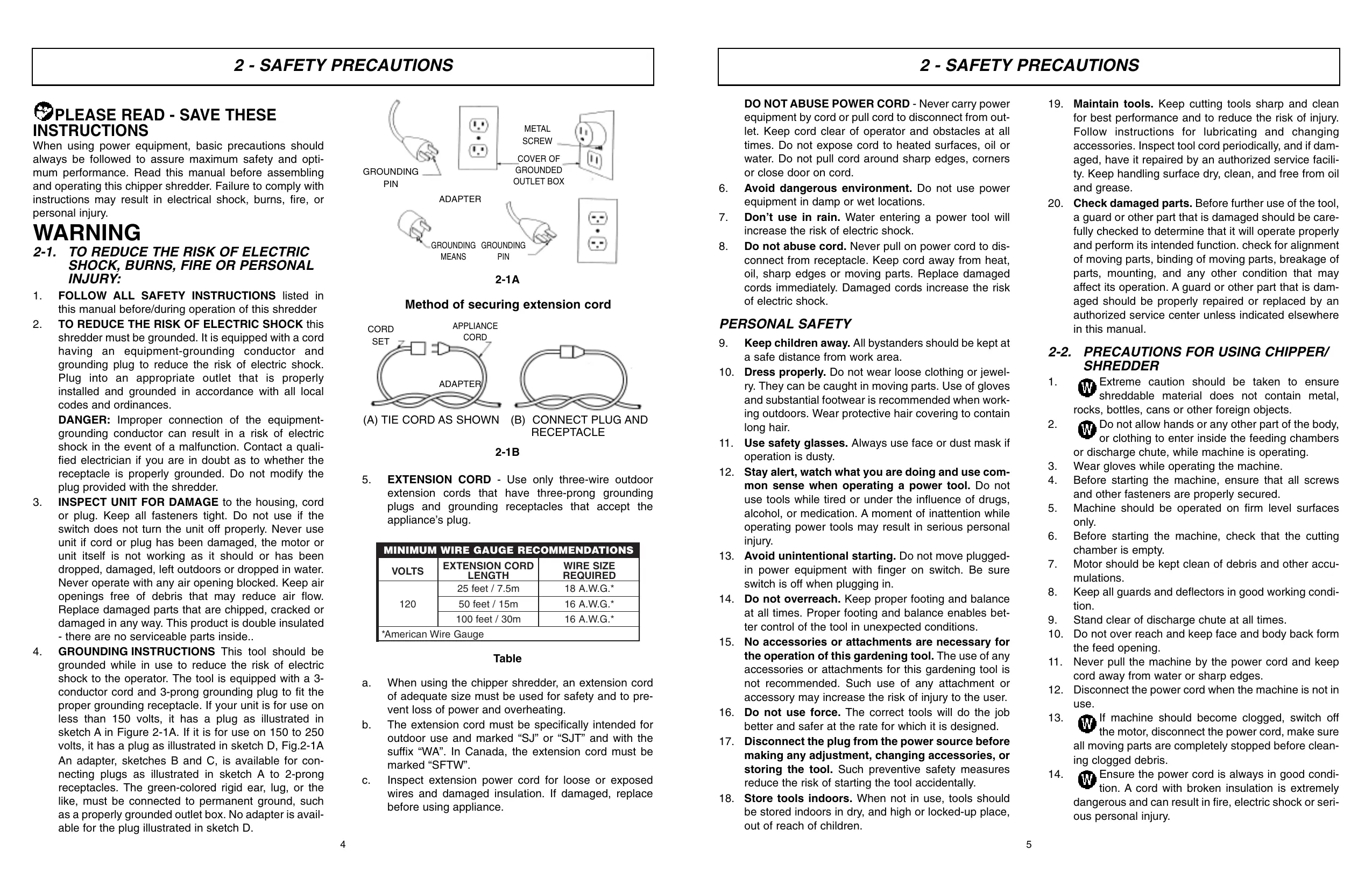
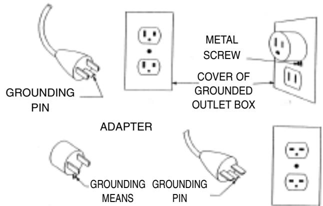
GROUNDING INSTRUCTIONS This tool should be grounded while in use to reduce the risk of electric shock to the operator. The tool is equipped with a 3-conductor cord and 3-prong grounding plug to fit the proper grounding receptacle. If your unit is for use on less than 150 volts, it has a plug as illustrated in sketch A in Figure 2-1A. If it is for use on 150 to 250 volts, it has a plug as illustrated in sketch D, Fig.2-1A. An adapter, sketches B and C, is available for connecting plugs as illustrated in sketch A to 2-prong receptacles. The green-colored rigid ear, lug, or the like, must be connected to permanent ground, such as a properly grounded outlet box. No adapter is available for the plug illustrated in sketch D.
2-1A
Method of securing extension cord
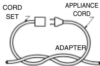
(A) TIE CORD AS SHOWN
(B) CONNECT PLUG AND RECEPTACLE
- EXTENSION CORD - Use only three-wire outdoor extension cords that have three-prong grounding plugs and grounding receptacles that accept the appliance's plug.
2-1B
| MINIMUM WIRE GAUGE RECOMMENDATIONS | ||
| VOLTS | EXTENSION CORD LENGTH | WIRE SIZE REQUIRED |
| 120 | 25 feet / 7.5m | 18 A.W.G.* |
| 50 feet / 15m | 16 A.W.G.* | |
| 100 feet / 30m | 16 A.W.G.* | |
| *American Wire Gauge | ||
Table
a. When using the chipper shredder, an extension cord of adequate size must be used for safety and to prevent loss of power and overheating.
b. The extension cord must be specifically intended for outdoor use and marked "SJ" or "SJT" and with the suffix "WA". In Canada, the extension cord must be marked "SFTW".
c. Inspect extension power cord for loose or exposed wires and damaged insulation. If damaged, replace before using appliance.
2 - SAFETY PRECAUTIONS
DO NOT ABUSE POWER CORD - Never carry power equipment by cord or pull cord to disconnect from outlet. Keep cord clear of operator and obstacles at all times. Do not expose cord to heated surfaces, oil or water. Do not pull cord around sharp edges, corners or close door on cord.
- Avoid dangerous environment. Do not use power equipment in damp or wet locations.
- Don't use in rain. Water entering a power tool will increase the risk of electric shock.
- Do not abuse cord. Never pull on power cord to disconnect from receptacle. Keep cord away from heat, oil, sharp edges or moving parts. Replace damaged cords immediately. Damaged cords increase the risk of electric shock.
PERSONAL SAFETY
- Keep children away. All bystanders should be kept at a safe distance from work area.
- Dress properly. Do not wear loose clothing or jewelry. They can be caught in moving parts. Use of gloves and substantial footwear is recommended when working outdoors. Wear protective hair covering to contain long hair.
- Use safety glasses. Always use face or dust mask if operation is dusty.
- Stay alert, watch what you are doing and use common sense when operating a power tool. Do not use tools while tired or under the influence of drugs, alcohol, or medication. A moment of inattention while operating power tools may result in serious personal injury.
- Avoid unintentional starting. Do not move plugged-in power equipment with finger on switch. Be sure switch is off when plugging in.
- Do not overreach. Keep proper footing and balance at all times. Proper footing and balance enables better control of the tool in unexpected conditions.
- No accessories or attachments are necessary for the operation of this gardening tool. The use of any accessories or attachments for this gardening tool is not recommended. Such use of any attachment or accessory may increase the risk of injury to the user.
- Do not use force. The correct tools will do the job better and safer at the rate for which it is designed.
- Disconnect the plug from the power source before making any adjustment, changing accessories, or storing the tool. Such preventive safety measures reduce the risk of starting the tool accidentally.
-
Store tools indoors. When not in use, tools should be stored indoors in dry, and high or locked-up place, out of reach of children.
-
Maintain tools. Keep cutting tools sharp and clean for best performance and to reduce the risk of injury. Follow instructions for lubricating and changing accessories. Inspect tool cord periodically, and if damaged, have it repaired by an authorized service facility. Keep handling surface dry, clean, and free from oil and grease.
- Check damaged parts. Before further use of the tool, a guard or other part that is damaged should be carefully checked to determine that it will operate properly and perform its intended function. check for alignment of moving parts, binding of moving parts, breakage of parts, mounting, and any other condition that may affect its operation. A guard or other part that is damaged should be properly repaired or replaced by an authorized service center unless indicated elsewhere in this manual.
2-2. PRECAUTIONS FOR USING CHIPPER/SHREDDER
- Extreme caution should be taken to ensure shreddable material does not contain metal, rocks, bottles, cans or other foreign objects.
- Do not allow hands or any other part of the body, or clothing to enter inside the feeding chambers or discharge chute, while machine is operating.
- Wear gloves while operating the machine.
- Before starting the machine, ensure that all screws and other fasteners are properly secured.
- Machine should be operated on firm level surfaces only.
- Before starting the machine, check that the cutting chamber is empty.
- Motor should be kept clean of debris and other accumulations.
- Keep all guards and deflectors in good working condition.
- Stand clear of discharge chute at all times.
- Do not over reach and keep face and body back form the feed opening.
- Never pull the machine by the power cord and keep cord away from water or sharp edges.
- Disconnect the power cord when the machine is not in use.
- If machine should become clogged, switch off the motor, disconnect the power cord, make sure all moving parts are completely stopped before cleaning clogged debris.
- Ensure the power cord is always in good condition. A cord with broken insulation is extremely dangerous and can result in fire, electric shock or serious personal injury.
2 - SAFETY PRECAUTIONS
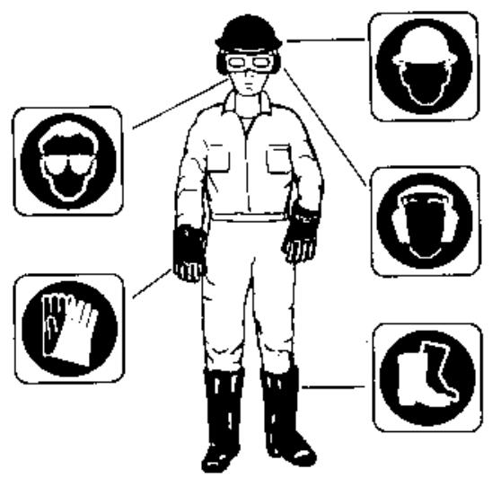
- The operation of any tool can result in foreign objects being thrown into your eyes, which can result in severe eye damage. Before operating power tool, always wear safety goggles or safety glasses with side shields and a full face shield when needed. We recommend wide Vision Safety Mask for use over eyeglasses or standard safety glasses with side shields.
2-3. EXPLANATION OF NOTE, WARNING, AND WARRANTY SYMBOL
- A NOTE is used to convey additional information, or highlight a particular explanation, or to expand a instruction.
- A WARNING identifies a procedure which, if not undertaken or if improperly done, can result in a serious personal injury or damage to the unit and/or both.
- (WARRANTY SYMBOL) serves notice that unless instructions or procedures are followed, any damage will void the warranty and repairs will be at owner's expense. Service other than user maintenance should be performed by a McCulloch Authorized Service Center. Damage or conditions caused BY improper maintenance practices which render this product inoperable will void the manufacturer's warranty.
- FOR WARRANTY OR SERVICE contact the nearest McCulloch Authorized Service Center.
Use of these personal safety items is highly recommended to reduce the risk of accidental injury.

2-1
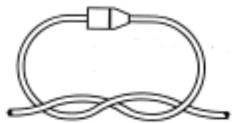
Never place hands into ejection chute as serious injury will occur.
2-4.INTERNATIONAL SYMBOLS
- Never place hands into discharge chute as serious injury will occur (Figure 2-1).
- Use of these personal safety items is highly recommended to reduce the risk of accidental injury (Figure 2-2).
SAVE THESE INSTRUCTIONS
2-2
3 - ASSEMBLY INSTRUCTIONS
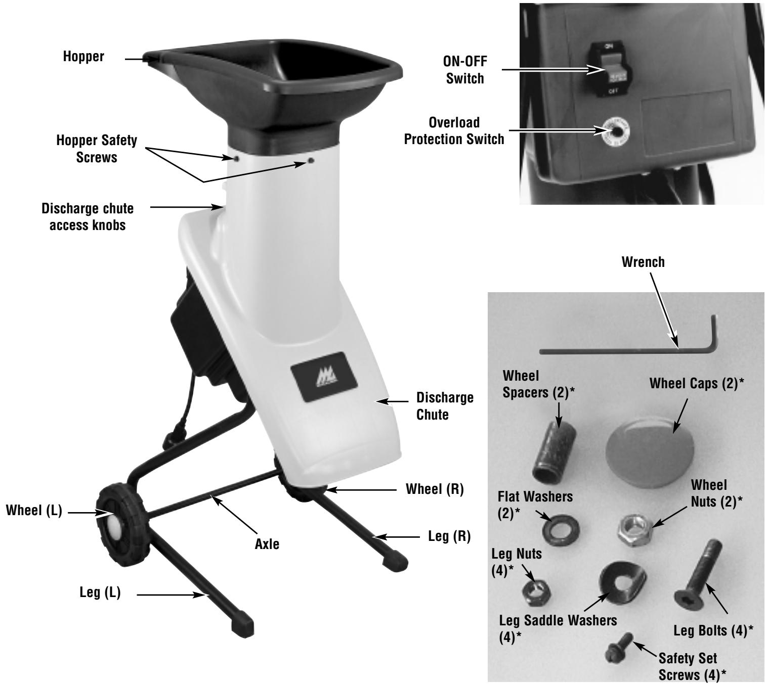
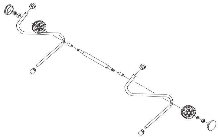
3-1. CONNECTING WHEEL ASSEMBLY
- Place legs onto axle. Put the wheel spacers and wheels onto the ends of the axle.
- Secure wheels using the flat wheel washers and wheel nuts.
- Put on wheel caps.

3-1A
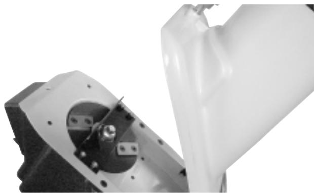
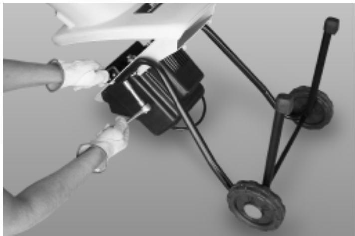
3-2. LEGS ASSEMBLY
- Open the hopper chute by turning the caging knob, then place the motor housing on a flat surface.
- Secure legs using the four bolts, saddle washers and nuts. (2 per side)
3-2A
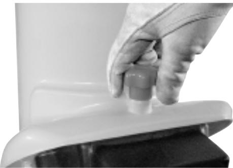
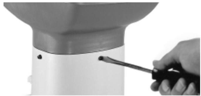
3-3. HOPPER ASSEMBLY
Place the hopper on top of the feed tube and align the fixing holes. Secure with the safety set screws.

3-3A
4 - OPERATING INSTRUCTIONS
4-1. OPERATION
Read and understand the safety instructions in this owners manual before using your shredder. Failure to comply can result in accidents involving fire, electric shock, or serious personal injury.
- Connect the shredder to a suitable power outlet.
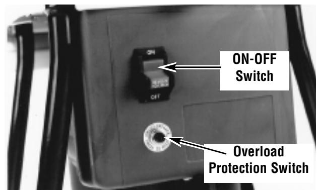
- To start and stop the shredder, depress the switch located at the rear of the Motor.
- To stop the shredder, switch to the off position. (Fig. 4-1)
4-1
4-2. OVERLOAD PROTECTION AND MOTOR
JAMMING If overfeeding clogs the machine the overload protection switch may cut out the motor. To restart, switch the machine off and disconnect the power cord.
Loosen discharge chute access knobs and open top cover assembly, then remove any clogged debris from the cutting chamber. If the top cover assembly becomes jammed and will not lift off, turn the V-cutter by pushing a piece of wood through the back chute of the top hopper to rotate the V-cutter to enable the top cover assembly to be removed. Reset motor overload protection switch. (See Fig. 4-1)
4-3. FEEDING LEAVES AND SMALL GARDEN CLIPPINGS - TOP HOPPER
The sloping chute of the top hopper is designed to accept leaves and small garden clippings.
Shredding and mulching is achieved by natural suction of the debris through the blade chamber. Do not overfeed and do not feed wet, soggy material into the garden shredder as this may clog the blade chamber and the discharge chute. (Fig. 4-3)

4-3
4-4. FEEDING TWIGS AND SMALL BRANCHES - TOP HOPPER
The smaller back chute of the top Hopper accepts medium to larger size garden clippings.
Shredding and mulching is achieved through the same action as the front chute. If a finer type mulch is required than is initially achieved, re-feed the mulch through again until the desired result is obtained. (Fig. 4-4).
Do not feed solid branches through the two Top Hopper chutes.

4-4
5 - MAINTENANCE INSTRUCTIONS
Your Shredder has been designed for a low level of maintenance, involving routine cleaning and inspection. The motor of the Shredder is maintenance free and requires no attention. For the best results the blades must be kept sharp at all times. The blades have dramatically less cutting power when blunt.
The Shredder will tear rather than cut when the blades are blunt. When this occurs rotate the double sided blades or replace the blades immediately.
WARNING
Before attempting any maintenance switch the machine off and disconnect the power cord.
- Switch the machine off and disconnect the power cord ensuring all moving parts are completely stopped.
- Wear gloves when attempting any maintenance to the cutting blades.
JAMMING if blades become jammed refer to disassembly instructions and then remove obstruction. (Fig. 5-1A)
- Open Top Hopper as illustrated in Fig. 5-1B

Take extreme care not to come in contact with cutting blades.
2. Remove obstruction from cutting chamber. Close Top Hopper and retighten discharge chute access knobs.
If discharge chute becomes clogged or cutting blades become jammed, under no circumstances should you place your hands in discharge chute to try to clear obstruction, as this will lead to serious injury.
5-1A
5-1B
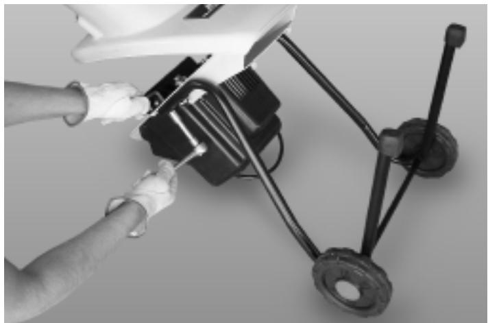
5-2. SHREDDING BLADES MAINTENANCE WARNING
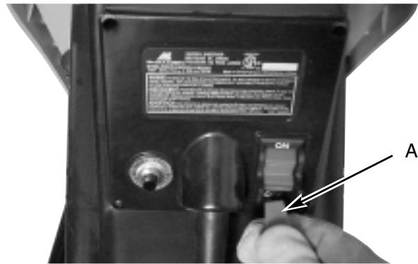
Before removing discharge chute access knobs, ensure the machine is switched off, the red safety switch extension lead (A) (Fig. 5-2A) is removed and wait until the machine comes to a complete stop.
To inspect or replace the double sided shredding blades, disconnect the power cord and open the Top Hopper.
To remove blades, remove the counter sunk screws with the hex wrench supplied (Fig. 5-2B). When blades are blunt on both sides replace with McCulloch blades and make sure they are screwed in tightly.
5-2A

5-2B
5-3. CLEANING
After use, always wipe clean the outside of the shredder to remove any build up of material with a damp cloth. Clean the inside of the cutting chamber and remove any left over material, Do not hose down with water.
6 - ONE YEAR LIMITED WARRANTY
1. DURATION
The duration of the warranty for this McCulloch product is as follows: ONE (1) YEAR from date of original purchase only when used for personal, family, household, farm or ranch, purposes, provided the unit is not used for rental purposes; NINETY (90) DAYS from date of original purchase when used for commercial, professional, institutional or rental purposes. This warranty gives you specific legal rights. You may also have other rights which vary from state to state. MCCulloCH CORPORATION HEREBY DISCLAIMS ALL IMPLIED WARRANTY AFTER THE APPLICABLE EXPIRATION DATES OF THIS EXPRESS LIMITED WARRANTY. (Some states do not allow limitations on how long an implied warranty lasts, so the above limitations may not apply to you.)
2. WHO GIVES THIS WARRANTY
McCulloch U.S.A
1-800-521-8559
10715 Springdale Avenue, Unit 2, Santa Fe Springs, CA 90670 USA
3. WHO RECEIVES THIS WARRANTY
A. The buyer (other than for purposes of resale) of the McCulloch Product.
B. Any person to whom such product is lawfully transferred within the duration of the implied or written warranty applicable to the product.
C. Any other person who is entitled by the terms of the warranty or under applicable state law to enforce against the Warrantor the obligation of the warranty. (The above mentioned parties are hereinafter referred to as "User.")
4. WHAT IS COVERED UNDER THIS WARRANTY
Any failure that occurs within the applicable duration of the warranty period that is the result of defects in materials or workmanship.
5. WHAT IS NOT COVERED UNDER THIS WARRANTY
A. Any incidental or consequential damages that may result from the failure or malfunction of the McCulloch product. (Some states do not allow the exclusion or limitation of incidental or consequential damages, so these limitations may not apply to you.)
B. Any failure that results from an accident, User abuse, neglect or failure to operate the product in accordance with the instructions provided in the User Manual(s) supplied with the product, or that results from improper servicing by an unauthorized repair facility.
C. Normal adjustments which are explained in the User Manual(s) provided with the product.
D. Any component(s) or accessories not sold or manufactured by the Warrantor.
E. Predelivery setup or assembly of units.
F. This warranty does not apply to accessories, normal maintenance or adjustment(s) of the product set forth in the User Manual(s).
6. RESPONSIBILITIES OF THE WARRANTYER UNDER THIS WARRANTY
A. Repair or replace components which have failed within the duration of the applicable warranty period at no cost to the User.
B. Ensure that the authorized repair station is reimbursed for parts and labor costs incurred due to performance of a warranty repair in accordance with established warranty policies and procedures.
7. RESPONSIBILITIES OF THE USER UNDER THIS WARRANTY
A. The User must deliver or ship the McCulloch product covered under this warranty to the dealer from whom it was originally purchased or to the nearest Authorized Service Center. Proof of purchase is required.
B. Freight costs, if any, will be borne by the user.
C. Use reasonable care in maintenance, operations and storage of the product as explained in the User Manual(s).
8. WHEN WARRANTYOR WILL PERFORM OBLIGATION UNDER THIS WARRANTY
A. Repair of warrantable products will be scheduled according to the normal work flow at the servicing location, depending on the availability of replacement parts.
B. Repair time which exceeds ten (10) days from the time the product was delivered to the servicing agent will extend the warranty coverage by the number of days the product remains inoperable.
C. If User does not receive satisfactory results from local servicing outlet, User must contact McCulloch Corporation, by calling our toll-free telephone number.
MANUEL DE UTILISATION
Poids Net 48.5 Lbs. (22 Kg)
2 - MEASURES DE SECURITE
LIRE ET CONSERVER CES INSTRUCTIONS
10715 Springdale Avenue, Unit 2, Santa Fe Springs, CA 90670 USA
3. QUI EST COUVERT PAR CETTE GARANTIE
Poids Net 48.5 Lbs. (22 Kg)
- Place legs onto axle. Put the wheel spacers and wheels onto the ends of the axle.
- Secure wheels using the flat wheel washers and wheel nuts.
- Put on wheel caps.
3-1A
3-3. HOPPER ASSEMBLY
Place the hopper on top of the feed tube and align the fixing holes. Secure with the safety set screws.
3-3A
3-2. LEGS ASSEMBLY
- Open the hopper chute by turning the caging knob, then place the motor housing on a flat surface.
- Secure legs using the four bolts, saddle washers and nuts. (2 per side)
3-2A
10715 Springdale Avenue, Unit 2, Santa Fe Springs, CA 90670 USA