
PRIME Z790M-PLUS D4 - Wall socket ASUS - Free user manual and instructions
Find the device manual for free PRIME Z790M-PLUS D4 ASUS in PDF.
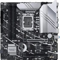


| Product Type | Motherboard |
| Brand | ASUS |
| Model | PRIME Z790M-PLUS D4 |
| Form Factor | Micro-ATX |
| Dimensions (W x D) | 244 mm x 244 mm |
| Weight | 0.8 kg |
| CPU Socket | LGA1700 |
| Supported CPUs | Intel Core 13th & 12th Gen |
| Memory Slots | 4 x DIMM, max 128 GB |
| Memory Type | DDR4 |
| Expansion Slots | 1 x PCIe 5.0 x16, 2 x PCIe 4.0 x16, 2 x PCIe 3.0 x1 |
| Storage Interfaces | 3 x M.2 (PCIe 4.0 x4), 4 x SATA 6 Gb/s |
| USB Ports (Rear) | 2 x USB 3.2 Gen2, 4 x USB 3.2 Gen1, 2 x USB 2.0 |
| Video Outputs | 1 x HDMI 2.1, 1 x DisplayPort 1.4 |
| Audio | Realtek ALC897 7.1 Surround Sound |
| LAN | Realtek 2.5 Gb Ethernet |
| Power Supply | ATX 24-pin + 8+4 pin EPS |
| Operating Temperature | 0°C to 40°C |
| Cleaning Instructions | Use compressed air; avoid liquids |
| Repairability Index | 7/10 |
| Spare Parts Availability | Batteries, capacitors, heatsinks |
| Warranty | 3 years limited |
Frequently Asked Questions - PRIME Z790M-PLUS D4 ASUS
User questions about PRIME Z790M-PLUS D4 ASUS
0 question about this device. Answer the ones you know or ask your own.
Ask a new question about this device
Download the instructions for your Wall socket in PDF format for free! Find your manual PRIME Z790M-PLUS D4 - ASUS and take your electronic device back in hand. On this page are published all the documents necessary for the use of your device. PRIME Z790M-PLUS D4 by ASUS.
USER MANUAL PRIME Z790M-PLUS D4 ASUS
Copyright © 2022 ASUSTeK COMPUTER INC. All Rights Reserved.
No part of this manual, including the products and software described in it, may be reproduced, transmitted, transcribed, stored in a retrieval system, or translated into any language in any form or by any means, except documentation kept by the purchaser for backup purposes, without the express written permission of ASUSTeK COMPUTER INC. ("ASUS").
Product warranty or service will not be extended if: (1) the product is repaired, modified or altered, unless such repair, modification of alteration is authorized in writing by ASUS; or (2) the serial number of the product is defaced or missing.
ASUS PROVIDES THIS MANUAL "AS IS" WITHOUT WARRANTY OF ANY KIND, EITHER EXPRESS OR IMPLIED, INCLUDING BUT NOT LIMITED TO THE IMPLIED WARRANTIES OR CONDITIONS OF MERCHANTABILITY OR FITNESS FOR A PARTICULAR PURPOSE. IN NO EVENT SHALL ASUS, ITS DIRECTORS, OFFICERS, EMPLOYEES OR AGENTS BE LIABLE FOR ANY INDIRECT, SPECIAL, INCIDENTAL, OR CONSEQUENTIAL DAMAGES (INCLUDING DAMAGES FOR LOSS OF PROFITS, LOSS OF BUSINESS, LOSS OF USE OR DATA, INTERRUPTION OF BUSINESS AND THE LIKE), EVEN IF ASUS HAS BEEN ADVISED OF THE POSSIBILITY OF SUCH DAMAGES ARISING FROM ANY DEFECT OR ERROR IN THIS MANUAL OR PRODUCT.
SPECIFICATIONS AND INFORMATION CONTAINED IN THIS MANUAL ARE FURNISHED FOR INFORMATIONAL USE ONLY, AND ARE SUBJECT TO CHANGE AT ANY TIME WITHOUT NOTICE, AND SHOULD NOT BE CONSTRUED AS A COMMITMENT BY ASUS. ASUS ASSUMES NO RESPONSIBILITY OR LIABILITY FOR ANY ERRORS OR INACCURACIES THAT MAY APPEAR IN THIS MANUAL, INCLUDING THE PRODUCTS AND SOFTWARE DESCRIBED IN IT.
Products and corporate names appearing in this manual may or may not be registered trademarks or copyrights of their respective companies, and are used only for identification or explanation and to the owners' benefit, without intent to infringe.
Contents
Safety information....iv
About this guide....v
PRIME Z790M-PLUS D4 specifications summary ...... vi
Package contents....x
Chapter 1: Product Introduction
1.1 Before you proceed 1-1
1.2 Motherboard layout....1-2
Chapter 2: Basic Installation
2.1 Building your PC system....2-1
2.1.1 CPU installation....2-1
2.1.2 Cooling system installation....2-3
2.1.3 DIMM installation....2-6
2.1.4 M.2 installation 2-7
2.1.5 Motherboard installation....2-9
2.1.6 ATX power connection....2-11
2.1.7 SATA device connection....2-12
2.1.8 Front I/O connector 2-13
2.1.9 Expansion card installation 2-14
2.2 Motherboard rear and audio connections 2-16
2.2.1 Rear I/O connection 2-16
2.2.2 Audio I/O connections....2-17
2.3 Starting up for the first time....2-20
2.4 Turning off the computer 2-20
Chapter 3: BIOS and RAID Support
3.1 Knowing BIOS....3-1
3.2 BIOS setup program....3-2
3.3 ASUS EZ Flash 3....3-3
3.4 ASUS CrashFree BIOS 3....3-4
3.5 RAID configurations 3-5
Appendix
Notices ...... A-1
Warranty....A-6
ASUS contact information.... A-8
Service and Support ...... A-8
Safety information
Electrical safety
- To prevent electrical shock hazard, disconnect the power cable from the electrical outlet before relocating the system.
- When adding or removing devices to or from the system, ensure that the power cables for the devices are unplugged before the signal cables are connected. If possible, disconnect all power cables from the existing system before you add a device.
- Before connecting or removing signal cables from the motherboard, ensure that all power cables are unplugged.
- Seek professional assistance before using an adapter or extension cord. These devices could interrupt the grounding circuit.
- Ensure that your power supply is set to the correct voltage in your area. If you are not sure about the voltage of the electrical outlet you are using, contact your local power company.
- If the power supply is broken, do not try to fix it by yourself. Contact a qualified service technician or your retailer.
Operation safety
- Before installing the motherboard and adding devices on it, carefully read all the manuals that came with the package.
- Before using the product, ensure all cables are correctly connected and the power cables are not damaged. If you detect any damage, contact your dealer immediately.
- To avoid short circuits, keep paper clips, screws, and staples away from connectors, slots, sockets and circuitry.
- Avoid dust, humidity, and temperature extremes. Do not place the product in any area where it may become wet.
- Place the product on a stable surface.
- If you encounter technical problems with the product, contact a qualified service technician or your retailer.
- Your motherboard should only be used in environments with ambient temperatures between 0°C and 40°C.
Button/Coin Batteries Safety Information


About this guide
This user guide contains the information you need when installing and configuring the motherboard.
How this guide is organized
This guide contains the following parts:
• Chapter 1: Product Introduction
This chapter describes the features of the motherboard and the new technology it supports. It includes description of the switches, jumpers, and connectors on the motherboard.
• Chapter 2: Basic Installation
This chapter lists the hardware setup procedures that you have to perform when installing system components.
• Chapter 3: BIOS and RAID Support
This chapter tells how to boot into the BIOS, upgrade BIOS using the EZ Flash Utility and support on RAID.
Where to find more information
Refer to the following sources for additional information and for product and software updates.
1. ASUS website
The ASUS website (www.asus.com) provides updated information on ASUS hardware and software products.
2. Optional documentation
Your product package may include optional documentation, such as warranty flyers, that may have been added by your dealer. These documents are not part of the standard package.
Conventions used in this guide
To ensure that you perform certain tasks properly, take note of the following symbols used throughout this user guide.

CAUTION: Information to prevent damage to the components and injuries to yourself when trying to complete a task.

IMPORTANT: Instructions that you MUST follow to complete a task.

NOTE: Tips and additional information to help you complete a task.
PRIME Z790M-PLUS D4 specifications summary
| CPU | Intel® Socket LGA1700 for 13thGen Intel® CoreTM Processors & 12thGen Intel® CoreTM, Pentium® Gold and Celeron® Processors*Supports Intel® Turbo Boost Technology 2.0 and Intel® Turbo Boost Max Technology 3.0*** Refer to www.asus.com for CPU support list.** Intel® Turbo Boost Max Technology 3.0 support depends on the CPU types. |
| Chipset | Intel® Z790 Chipset |
| Memory | 4 x DIMM, Max. 128GB, DDR4 5333(OC)/5133(OC)/5066(OC)/5000(OC)/4800(OC)/4700(OC)/4600(OC)/4500(OC)/4400(OC)/4266(OC)/4133(OC)/4000(OC)/3866(OC)/3733(OC)/3600(OC)/3466(OC)/3400(OC)/3333(OC)/3200/3000/2933/2800/2666/2400/2133Non-ECC, Un-buffered Memory*Dual Channel Memory ArchitectureSupports Intel® Extreme Memory Profile (XMP)OptiMem II* Supported memory types, data rate(Speed), and number of DRAM modules vary depending on the CPU and memory configuration, for more information refer to www.asus.com for memory support list. |
| Graphics | 1 x DisplayPort**1 x HDMI® port**** Graphics specifications may vary between CPU types. Please refer to www.intel.com for any updates.** Supports max. 4K@60Hz as specified in DisplayPort 1.4.*** Supports 4K@60Hz as specified in HDMI® 2.1. |
| Expansion Slots | Intel® 13th& 12thGen Processors*1 x PCIe 5.0 x16 slotIntel® Z790 Chipset1 x PCIe 4.0 x16 slot (supports x4 mode)2 x PCIe 4.0 x1 slots* Please check the PCIe bifurcation table on the support site (https://www.asus.com/support/FAQ/1037507/).Note: To ensure compatibility of the device installed, please refer to https://www.asus.com/support/ for the list of supported peripherals. |
| Storage | Total supports 3 x M.2 slots and 4 x SATA 6Gb/s ports*Intel® 13th& 12thGen ProcessorsM.2_1 slot (Key M), type 2242/2260/2280 (supports PCIe 4.0 x4 mode)Intel® Z790 ChipsetM.2_2 slot (Key M), type 2260/2280 (supports PCIe 4.0 x4 mode)M.2_3 slot (Key M), type 2242/2260/2280(supports PCIe 4.0 x4 & SATA modes)4 x SATA 6Gb/s ports* Intel® Rapid Storage Technology supports PCIe RAID 0/1/5/10 and SATA RAID 0/1/5/10. |
| Ethernet | 1 x Intel® 1Gb EthernetASUS LANGuard |
| Wireless & Bluetooth® | M.2 slot only (Key E, CNVi & PCIe)*Wi-Fi module is sold separately. |
(continued on the next page)
PRIME Z790M-PLUS D4 specifications summary
| USB | Rear USB (Total 8 ports)1 x USB 3.2 Gen 2x2 port (1 x USB Type-C®)1 x USB 3.2 Gen 2 port (1 x Type-A)4 x USB 3.2 Gen 1 ports (4 x Type-A)2 x USB 2.0 ports (2 x Type-A)Front USB (Total 7 ports)1 x USB 3.2 Gen 1 connector (supports USB Type-C®)1 x USB 3.2 Gen 1 header supports 2 additional USB 3.2 Gen 1 ports2 x USB 2.0 headers support 4 additional USB 2.0 ports** USB_E1 port, USB_E2 port, USB_E3 port and USB_E4 port share the bandwidth. |
| Audio | Realtek 7.1 Surround Sound High Definition Audio CODEC*- Supports: Jack-detection, Multi-streaming, Front Panel Jack-retasking-Supports up to 24-Bit/192 kHz playbackAudio Features-Audio Shielding-Premium audio capacitors-Dedicated audio PCB layers* A chassis with an HD audio module in the front panel is required to support 7.1 Surround Sound audio output. |
| Back Panel I/O Ports | 1 x USB 3.2 Gen 2x2 port (1 x USB Type-C®)1 x USB 3.2 Gen 2 port (1 x Type-A)4 x USB 3.2 Gen 1 ports (4 x Type-A)2 x USB 2.0 ports (2 x Type-A)1 x DisplayPort1 x HDMI® port1 x Intel® 1Gb Ethernet port3 x Audio jacks |
| Internal I/O Connectors | Fan and cooling related1 x 4-pin CPU Fan header1 x 4-pin CPU OPT Fan header1 x 4-pin AIO_Pump header3 x 4-pin Chassis Fan headersPower related1 x 24-pin Main Power connector1 x 8-pin +12V Power connector1 x 4-pin +12V Power connectorStorage related3 x M.2 slots (Key M)4 x SATA 6Gb/s portsUSB1 x USB 3.2 Gen 1 connector (supports USB Type-C®)1 x USB 3.2 Gen 1 header supports 2 additional USB 3.2 Gen 1 ports2 x USB 2.0 headers support 4 additional USB 2.0 ports |
(continued on the next page)
PRIME Z790M-PLUS D4 specifications summary
Miscellaneous
3 x Addressable Gen 2 headers
1 x Aura RGB header
1 x Clear CMOS header
1 x COM Port header
1 x Front Panel Audio header (AAFP)
1 x M.2 slot (Key E)
1 x S/PDIF Out header
1 x SPI TPM header (14-1pin)
1 x 20-3 pin System Panel header with Chassis intrude function
1 x Thunderbolt™ (USB4®) header
ASUS 5X PROTECTION III
- DIGI+ VRM (- Digital power design with DrMOS)
- LANGuard
- Overvoltage Protection
- SafeSlot Core+
- Stainless-Steel Back I/O
ASUS Q-Design
- Q-DIMM
- Q-LED Core
- Q-Slot
ASUS Thermal Solution
- VRM heatsink design
ASUS EZ DIY
- ProCool
Aura Sync
- Aura RGB header
- Addressable Gen 2 headers
ASUS Exclusive Software
Armoury Crate
- Aura Sync
- Fan Xpert 4 (with AI Cooling II)
- Power Saving
AI Suite 3
- TurboV EVO
- PC Cleaner
- DIGI+ VRM
ASUS CPU-Z
Norton 360 Deluxe (60 Days Free Trial)
WinRAR
(continued on the next page)
PRIME Z790M-PLUS D4 specifications summary
| Software Features | UEFI BIOSASUS EZ DIY- ASUS CrashFree BIOS 3- ASUS EZ Flash 3- ASUS UEFI BIOS EZ Mode |
| BIOS 192 (128+64) Mb Flash ROM, UEFI AMI BIOS | |
| Manageability WOL by PME, PXE | |
| Operating System Windows ® 11, Windows ® 10 64-bit | |
| Form Factor | mATX Form Factor9.6 inch x 9.6 inch (24.4 cm x 24.4 cm) |

Specifications are subject to change without notice. Please refer to the ASUS website for the latest specifications.
Package contents
Check your motherboard package for the following items.
| Motherboard 1 x PRIME Z790M-PLUS D4 motherboard | |
| Cables 2 x SATA 6Gb/s cables | |
| Miscellaneous | 1 x I/O Shield |
| 2 x Screw packages for M.2 SSD* | |
| * The package including 2 screws and 1 nut is for installing an M.2 WIFI module into the M.2 WIFI slot and an M.2 SSD module into the M.2_2 slot. | |
Documentation 1 x User guide

If any of the above items is damaged or missing, contact your retailer.
Product Introduction
1.1 Before you proceed
Take note of the following precautions before you install motherboard components or change any motherboard settings.

- Unplug the power cord from the wall socket before touching any component.
- Before handling components, use a grounded wrist strap or touch a safely grounded object or a metal object, such as the power supply case, to avoid damaging them due to static electricity.
- Hold components by the edges to avoid touching the ICs on them.
- Whenever you uninstall any component, place it on a grounded antistatic pad or in the bag that came with the component.
- Before you install or remove any component, ensure that the ATX power supply is switched off or the power cord is detached from the power supply. Failure to do so may cause severe damage to the motherboard, peripherals, or components.

- The pin definitions in this chapter are for reference only. The pin names depend on the location of the header/jumper/connector.
- For more information on installing your motherboard, please scan the QR code below:

1.2 Motherboard layout

| Layout contents Page | |
| 1. CPU socket 1-4 | |
| 2. DIMM slots 1-5 | |
| 3. Expansion slots 1-7 | |
| 4. Fan and Pump headers 1-8 | |
| 5. Power connectors 1-9 | |
| 6. M.2 slots (SOCKET 3) 1-10 | |
| 7. SATA 6Gb/s ports 1-11 | |
| 8. USB 3.2 Gen 1 Type-C® Front Panel connector 1-12 | |
| 9. USB 3.2 Gen 1 header 1-12 | |
| 10. USB 2.0 headers 1-13 | |
| 11. Addressable Gen 2 headers 1-14 | |
| 12. Aura RGB header 1-15 | |
| 13. Clear CMOS header 1-16 | |
| 14. COM Port header | 1-17 |
| 15. Front Panel Audio header | 1-17 |
| 16. M.2 slot (Key E) | 1-18 |
| 17. S/PDIF Out header | 1-18 |
| 18. SPI TPM header (14-1pin) | 1-19 |
| 19. System Panel header | 1-20 |
| 20. ThunderboltTM (USB4®) header | 1-21 |
1. CPU socket
The motherboard comes with a LGA1700 socket designed for 13th Gen Intel® Core™ Processors and 12th Gen Intel® Core™, Pentium® Gold and Celeron® Processors.


- Ensure that you install the correct CPU designed for LGA1700 socket only. DO NOT install a CPU designed for other sockets on the LGA1700 socket.
- The CPU fits in only one correct orientation. DO NOT force the CPU into the socket to prevent bending the connectors on the socket and damaging the CPU.
- Ensure that all power cables are unplugged before installing the CPU.
- Upon purchase of the motherboard, ensure that the PnP cap is on the socket and the socket contacts are not bent. Contact your retailer immediately if the PnP cap is missing, or if you see any damage to the PnP cap/socket contacts/motherboard components. ASUS will shoulder the cost of repair only if the damage is shipment/transit-related.
- Keep the cap after installing the motherboard. ASUS will process Return Merchandise Authorization (RMA) requests only if the motherboard comes with the cap on the LGA1700 socket.
- The product warranty does not cover damage to the socket contacts resulting from incorrect CPU installation/removal, or misplacement/loss/incorrect removal of the PnP cap.
2. DIMM slots
The motherboard comes with Dual Inline Memory Modules (DIMM) slots designed for DDR4 (Double Data Rate 4) memory modules.

A DDR4 memory module is notched differently from a DDR, DDR2, or DDR3 module. DO NOT install a DDR, DDR2, or DDR3 memory module to the DDR4 slot.

Recommended memory configurations
Memory configurations
You may install 4 GB, 8 GB, 16 GB, and 32 GB unbuffered and non-ECC DDR4 DIMMs into the DIMM sockets.

You may install varying memory sizes in Channel A and Channel B. The system maps the total size of the lower-sized channel for the dual-channel configuration. Any excess memory from the higher-sized channel is then mapped for single-channel operation.

- The default memory operation frequency is dependent on its Serial Presence Detect (SPD), which is the standard way of accessing information from a memory module. Under the default state, some memory modules for overclocking may operate at a lower frequency than the vendor-marked value.
- For system stability, use a more efficient memory cooling system to support a full memory load or overclocking condition.
- Always install the DIMMs with the same CAS Latency. For an optimum compatibility, we recommend that you install memory modules of the same version or data code (D/C) from the same vendor. Check with the vendor to get the correct memory modules.
- Visit the ASUS website for the latest QVL.
3. Expansion slots

Unplug the power cord before adding or removing expansion cards. Failure to do so may cause you physical injury and damage motherboard components.

Please refer to the following tables for the recommended VGA configuration and Hyper M.2 configuration.
Recommended VGA configuration
| Slot Slot Description | Single VGA Dual VGA | |
| 1. PCIEX16(G5) x16 x16 | ||
| 2. PCIEX16(G4) | - | x4 |

Connect chassis fans to the chassis fan connectors when using multiple graphics cards for better thermal environment.
PCIe bifurcation & M.2 settings in PCIe x16 slots (from CPU)
| Slot Description | Quantity of identifiable M.2 SSD (pcs) | ||
| Situation 1 | Situation 2 | ||
| 1 | PCIEX16(G5) | 1 (x16)* | 2 (x8+x8)** |
| * Install an M.2 SSD card to the M.2_1 or M.2_3 slot on the Hyper M.2 X16 series card.** Install two M.2 SSD cards to the M.2_1 and M.2_3 slots on the Hyper M.2 X16 series card. | |||

- Additional PCIe bifurcation and M.2 settings for RAID function are also supported when a Hyper M.2 x16 series card is installed.
- For full details on the PCIe bifurcation, you may visit the support site at https://www.asus.com/support/FAQ/1037507/. • The Hyper M.2 x16 series card is sold separately.
- Adjust the PCIe bifurcation under BIOS settings.
4. Fan and Pump headers
The Fan and Pump headers allow you to connect fans or pumps to cool the system.


- DO NOT forget to connect the fan cables to the fan headers. Insufficient air flow inside the system may damage the motherboard components. These are not jumpers! Do not place jumper caps on the fan headers!
- Ensure the cable is fully inserted into the header.
| Header Max. Current Max. Power Default Speed Shared Control | |
| CPU_FAN 1A 12W Q-Fan Controlled - | |
| CPU_OPT 1A 12W Q-Fan Controlled - | |
| CHA_FAN1 1A 12W Q-Fan Controlled - | |
| CHA_FAN2 1A 12W Q-Fan Controlled - | |
| CHA_FAN3 1A 12W Q-Fan Controlled - | |
| AIO_PUMP 1A 12W Full-Speed - |
5. Power connectors
These Power connectors allow you to connect your motherboard to a power supply. The power supply plugs are designed to fit in only one orientation. Find the proper orientation and push down firmly until the power supply plugs are fully inserted.


Ensure to connect the 8-pin power plug, or connect both the 8-pin and 4-pin power plugs.
- We recommend that you use a PSU with a higher power output when configuring a system with more power-consuming devices. The system may become unstable or may not boot up if the power is inadequate.
- If you want to use two or more high-end PCI Express x16 cards, use a PSU with 1000W power or above to ensure the system stability.
6. M.2 slots
The M.2 slots allow you to install M.2 devices such as M.2 SSD modules.

A M.2_1(SOCKET3)
B M.2_2(SOCKET3)
C M.2_3(SOCKET3)


- Intel® 13th and 12th Gen processors:
- M.2_1 supports PCIe 4.0 x4 mode M Key design and type 2242/2260/2280 storage devices.
- Intel® Z790 Chipset
- M.2_2 supports PCIe 4.0 x4 mode M Key design and type 2260/2280 storage devices.
- M.2_3 supports PCIe 4.0 x4 and SATA modes M Key design and type 2242/2260/2280 storage devices.
- Intel® Rapid Storage Technology supports PCIe RAID 0/1/5/10 and SATA RAID 0/1/5/10.

The M.2 SSD module is purchased separately.
7. SATA 6Gb/s ports
The SATA 6Gb/s ports allow you to connect SATA devices such as optical disc drives and hard disk drives via SATA cables.
NOTE: Connect the right-angle side of SATA signal cable to SATA device. You may also connect the right-angle side of SATA cable to the onboard SATA port to avoid mechanical conflict with huge graphics cards.

If you installed SATA storage devices, you can create a RAID 0, 1, 5, and 10 configuration with the Intel® Rapid Storage Technology through the onboard Intel® Z790 chipset.

Before creating a RAID set, refer to the RAID Configuration Guide. You can download the RAID Configuration Guide from the ASUS website.
8. USB 3.2 Gen 1 Type-C® Front Panel connector
The USB 3.2 Gen 1 Type-C® connector allows you to connect a USB 3.2 Gen 1 Type-C® module for an additional USB 3.2 Gen 1 Type-C® port. The USB 3.2 Gen 1 Type-C® connector provides data transfer speeds of up to 5 Gb/s.


The USB 3.2 Gen 1 Type-C® module is purchased separately.
9. USB 3.2 Gen 1 header
The USB 3.2 Gen 1 header allows you to connect a USB 3.2 Gen 1 module for additional USB 3.2 Gen 1 ports. The USB 3.2 Gen 1 header provides data transfer speeds of up to 5 Gb/s.


The USB 3.2 Gen 1 module is purchased separately.
10. USB 2.0 headers
The USB 2.0 headers allow you to connect USB modules for additional USB 2.0 ports. The USB 2.0 header provides data transfer speeds of up to 480 Mb/s.


DO NOT connect a 1394 cable to the USB connectors. Doing so will damage the motherboard!

- The USB 2.0 module is purchased separately.
- USB_E1 port, USB_E2 port, USB_E3 port and USB_E4 port share the bandwidth.
11. Addressable Gen 2 headers
The Addressable Gen 2 headers allow you to connect individually addressable RGB WS2812B LED strips or WS2812B based LED strips.

The Addressable Gen 2 header supports WS2812B addressable RGB LED strips (5V/Data/Ground), with a maximum power rating of 3A (5V), and the addressable headers on this board can handle a combined maximum of 500 LEDs.

Before you install or remove any component, ensure that the power supply is switched off or the power cord is detached from the power supply. Failure to do so may cause severe damage to the motherboard, peripherals, or components.

• Actual lighting and color will vary with LED strip. - If your LED strip does not light up, check if the addressable RGB LED strip is connected in the correct orientation, and the 5V connector is aligned with the 5V header on the motherboard. - The addressable RGB LED strip will only light up when the system is powered on. - The addressable RGB LED strip is purchased separately.
12. Aura RGB header
The RGB header allows you to connect RGB LED strips.


The RGB header supports 5050 RGB multi-color LED strips (12V/G/R/B), with a maximum power rating of 3A (12V).

Before you install or remove any component, ensure that the power supply is switched off or the power cord is detached from the power supply. Failure to do so may cause severe damage to the motherboard, peripherals, or components.

• Actual lighting and color will vary with LED strip. - If your LED strip does not light up, check if the RGB LED extension cable and the RGB LED strip is connected in the correct orientation, and the 12V connector is aligned with the 12V header on the motherboard. - The LED strip will only light up when the system is powered on. • The LED strip is purchased separately.
13. Clear CMOS header
The Clear CMOS header allows you to clear the Real Time Clock (RTC) RAM in the CMOS, which contains the date, time, system passwords, and system setup parameters.

To erase the RTC RAM:
- Turn OFF the computer and unplug the power cord.
- Use a metal object such as a screwdriver to short the two pins.
- Plug the power cord and turn on the computer.
- Hold down the key during the boot process and enter BIOS setup to re-enter data.

DO NOT short-circuit the pins except when clearing the RTC RAM. Short-circuiting or placing a jumper cap will cause system boot failure!

If the steps above do not help, remove the onboard button cell battery and short the two pins again to clear the CMOS RTC RAM data. After clearing the CMOS, reinstall the button cell battery.
14. COM Port header
The COM (Serial) Port header allows you to connect a COM port module. Connect the COM port module cable to this header, then install the module to a slot opening on the system chassis.


The COM port module is purchased separately.
15. Front Panel Audio header
The front panel audio header is for a chassis-mounted front panel audio I/O module that supports HD Audio. Connect one end of the front panel audio I/O module cable to this header.


We recommend that you connect a high-definition front panel audio module to this connector to avail of the motherboard's high-definition audio capability.
16. M.2 slot (Key E)
The M.2(WIFI) slot allows you to install an M.2 Wi-Fi module (E-key, type 2230).
M.2(WIFI)


The M.2 Wi-Fi module is purchased separately.
17. S/PDIF Out header
The S/PDIF Out header allows you to connect the Sony/Philips Digital Interface (S/PDIF) Out module.


The S/PDIF module is purchased separately.
18. SPI TPM header (14-1pin)
This header supports a Trusted Platform Module (TPM) system with a Serial Peripheral Interface (SPI), allowing you to securely store keys, digital certificates, passwords, and data. A TPM system also helps enhance network security, protects digital identities, and ensures platform integrity.

TPM

The TPM module is purchased separately.
19. System Panel header
The System Panel header supports several chassis-mounted functions.


• System Power LED header (PLED)
The 2-pin and/or 3-1 pin headers allow you to connect the System Power LED. The System Power LED lights up when the system is connected to a power source, or when you turn on the system power, and blinks when the system is in sleep mode.
• Storage Device Activity LED header (HDD_LED)
The 2-pin header allows you to connect the Storage Device Activity LED. The Storage Device Activity LED lights up or blinks when data is read from or written to the storage device or storage device add-on card.
• System Warning Speaker header (SPEAKER)
The 4-pin header allows you to connect the chassis-mounted system warning speaker. The speaker allows you to hear system beeps and warnings.
• Power Button/Soft-off Button header (PWRSW)
The 3-1 pin header allows you to connect the system power button. Press the power button to power up the system, or put the system into sleep or soft-off mode (depending on the operating system settings).
- Reset button header (RESET)
The 2-pin header allows you to connect the chassis-mounted reset button. Press the reset button to reboot the system.
• Chassis intrusion header (CHASSIS)
The 2-pin header allows you to connect the chassis-mounted intrusion detection sensor or switch. The chassis intrusion sensor or switch sends a high-level signal to the header when a chassis component is removed or replaced, the signal is then generated as a chassis intrusion event.
20. Thunderbolt™ (USB4®) header
The Thunderbolt™ (USB4®) header allows you to connect an add-on Thunderbolt™ I/O card that supports Intel®'s Thunderbolt™ Technology, allowing you to connect Thunderbolt™-enabled devices to form a daisy chain-configuration.


- The add-on Thunderbolt™ I/O card and Thunderbolt™ cables are purchased separately.
- Please visit the official website of your purchased Thunderbolt™ card for more details on compatibility.
Basic Installation
2
2.1 Building your PC system

The diagrams in this section are for reference only. The motherboard layout may vary with models, but the installation steps are the same for all models.
2.1.1 CPU installation

- Ensure that you install the correct CPU designed for LGA1700 socket only. DO NOT install a CPU designed for LGA1155, LGA1156, LGA1151, and LGA1200 sockets on the LGA1700 socket.
- ASUS will not cover damages resulting from incorrect CPU installation/removal, incorrect CPU orientation/placement, or other damages resulting from negligence by the user.


Take caution when lifting the load lever, ensure to hold onto the load lever when releasing the load lever. Letting go of the load lever immediately after releasing it may cause the load lever to spring back and cause damage to your motherboard.


2.1.2 Cooling system installation

Apply Thermal Interface Material to the CPU cooling system and CPU before you install the cooling system, if necessary.
To install a CPU heatsink and fan assembly
1
2


- We recommend using an LGA1700 compatible cooling system when installing a cooling system to an Intel® 700 and 600 series motherboard.
- An additional hole for LGA1200 compatible cooling systems is also available on ASUS' Intel® 700 and 600 series motherboards, allowing you more flexibility when installing a cooling system to your motherboard. However, we still strongly advise you to consult with your cooling system vendor on the compatibility and functionality of the cooling system and ASUS motherboard.
- Push-pin type LGA1200 compatible cooling systems cannot be installed to this motherboard.
To install an AIO cooler

- We recommend using an LGA1700 compatible cooling system on an Intel® 700 and 600 series motherboard.
- Additional holes for LGA1200 compatible cooling systems are also available on ASUS' Intel® 700 and 600 series motherboards. However, we still strongly advise consulting with your cooling system vendor or manufacturer on the compatibility and functionality of the cooling system.
- If you wish to install an AIO cooler, we recommend installing the AIO cooler after installing the motherboard into the chassis.
1
2
2.1.3 DIMM installation


To remove a DIMM
2.1.4 M.2 installation
To install an M.2 WIFI card

To install an M.2 SSD card


Supported M.2 type varies per motherboard.
• The M.2 modules are purchased separately. - Use the screw and nut in the bundled 2-screw & 1-nut package when installing an M.2 SSD module into the M.2_2 socket.
2.1.5 Motherboard installation
- Install the ASUS I/O Shield to the chassis rear I/O panel.

Some sharp edges and points might cause physical injury. We recommend you put on cut or puncture resistant gloves before motherboard and I/O shield installation.

- Place the motherboard into the chassis, ensuring that its rear I/O ports are aligned to the chassis' rear I/O panel.

- Place eight (8) screws into the holes indicated by circles to secure the motherboard to the chassis.


DO NOT over tighten the screws! Doing so can damage the motherboard.
2.1.6 ATX power connection


Ensure to connect the 8-pin power plug, or connect both the 8-pin and 4-pin power plugs.
2.1.7 SATA device connection


2.1.8 Front I/O connector
To install the front panel connector
To install USB 3.2 Gen 1 Type-C® connector
This connector will only fit in one orientation. Push the connector until it clicks into place.
To install USB 3.2 Gen 1 connector
USB 3.2 Gen 1
To install USB 2.0 connector
To install front panel audio connector
2.1.9 Expansion card installation To install PCIe x16 cards

To install PCIe x1 cards
To install Thunderbolt™ series card


Ensure to install the Thunderbolt™ series card to the PCIEX16(G4) slot.

- Step 6 is optional, please connect a 6-pin PCIe power connector when you wish to use the USB Type-C® port Thunderbolt™ quick charge feature to charge a 5V or more device.
- The TypeC_1 port can support up to 20V devices, and the TypeC_2 port can support up to 9V devices when the 6-pin PCIe power connector is connected.
- The Thunderbolt™ series card is sold separately.
- Please visit the official website of your purchased Thunderbolt™ card for more details on compatibility.
2.2 Motherboard rear and audio connections
2.2.1 Rear I/O connection

Rear panel connectors
| 1. USB 2.0 ports 11 and 12 |
| 2. USB 3.2 Gen 2 Type-A port 9 |
| 3. Intel ® I219-V 1Gb Ethernet port* |
| 4. HDMI ® port |
| 5. DisplayPort |
| 6. USB 3.2 Gen 2x2 Type-C ® port C1 |
| 7. USB 3.2 Gen 1 Type-A ports 3, 4 and 5, 6 |
| 8. Audio jacks** |
* and ** : Refer to the tables below for LAN port LEDs, and audio port definitions.

We strongly recommend that you connect your devices to ports with matching data transfer rate. Please connect your USB 3.2 Gen 1 devices to USB 3.2 Gen 1 ports and your USB 3.2 Gen 2 devices to USB 3.2 Gen 2 ports for faster and better performance for your devices.
* Intel® I219-V 1Gb Ethernet port LED indications
 | Speed LED | |
| Status Description | ||
| OFF 10 Mbps | connection | |
| ORANGE 100 | Mbps connection | |
| GREEN 1 Gbps | connection | |
** Audio 2, 4, 5.1, or 7.1-channel configuration
| Port 2-channel 4-channel 5.1-channel 7.1-channel | ||||
| Light Blue(Rear panel) | -- Rear | Speaker | Out | Rear Speaker Out |
| Lime(Rear panel) | Front Speaker Out | Front Speaker Out | Front Speaker Out | Front Speaker Out |
| Pink(Rear panel) | - Center /Subwoofer | Center / Subwoofer | Center / Subwoofer | |
| Lime(Front panel) | --- Side Speaker | Out | ||
| Pink(Front panel) | ---- | |||

To configure a 7.1-channel audio output:
Use a chassis with HD audio module in the front panel to support a 7.1-channel audio output.
2.2.2 Audio I/O connections
Audio I/O ports

Connect to Headphone and Mic

Connect to 2-channel Speakers
![graph TD A["Audio INPUTS"] --> B["Resistor"] A --> C["Color Indicator"] D["Video Units"] --> E["Resistor"] F["Color Indicator"] --> G["Resistor"]](/content/2026/07/1414962/images/11d2f4efe3a875e4a297bf453001c6c27819791d5448050b2c6096a49121d77a.jpg)
Connect to 4-channel Speakers
![graph TD A["Audio Inputs"] --> B["Front"] A --> C["Center Subwoofer"] C --> D["Sensor"] D --> E["Output"]](/content/2026/07/1414962/images/b211d8d29c9ac780afc74f23bd5d1fce1f425a6b38e6cbca0f1b6f9cf9c54188.jpg)
Connect to 5.1-channel Speakers
![graph TD A["Audio INPUTS"] --> B["Rear"] A --> C["Front"] A --> D["Central Subwoofer"] A --> E["AUDIO INPUTS"] E --> F["Display Unit"] G["Radio Station"] --> H["Antenna"] I["Radio Station"] --> J["Antenna"] K["Radio Station"] --> L["Antenna"]](/content/2026/07/1414962/images/d84b8a34bf69c9b88be1a06fe91b05a37903fa8b1350cbcc0494a8025f636810.jpg)
Connect to 7.1-channel Speakers![graph TD A["Input"] --> B["Audio Inputs"] B --> C["Side"] B --> D["Center/ Subwoofer"] C --> E["Output"] D --> E E --> F["Server"] subgraph Display G["Speaker 1"] H["Speaker 2"] I["Speaker 3"] J["Speaker 4"] K["Speaker 5"] end style Display fill:#f9f,stroke:#333 style Server fill:#ccf,stroke:#333](/content/2026/07/1414962/images/7e30db8cbc5b9dedc187e07d29b35c37f69769da7e0f0699e2f3ba5bccb46897.jpg)
2.3 Starting up for the first time
- After making all the connections, replace the system case cover.
- Ensure that all switches are off.
- Connect the power cord to the power connector at the back of the system chassis.
- Connect the power cord to a power outlet that is equipped with a surge protector.
- Turn on the devices in the following order:
a. Monitor
b. External SCSI devices (starting with the last device on the chain) c. System power
- After applying power, the system power LED on the system front panel case lights up. For systems with ATX power supplies, the system LED lights up when you press the ATX power button. If your monitor complies with the "green" standards or if it has a "power standby" feature, the monitor LED may light up or change from orange to green after the system LED turns on.
The system then runs the power-on self tests (POST). While the tests are running, the BIOS beeps (refer to the BIOS beep codes table) or additional messages appear on the screen. If you do not see anything within 30 seconds from the time you turned on the power, the system may have failed a power-on test. Check the jumper settings and connections or call your retailer for assistance.
| BIOS Beep Description | |
| One short beep | VGA detectedQuick boot set to disabledNo keyboard detected |
| One continuous beep followed by two short beeps then a pause (repeated) | No memory detected |
| One continuous beep followed by three short beeps | No VGA detected |
| One continuous beep followed by four short beeps | Hardware component failure |
- At power on, hold down the key to enter the BIOS Setup. Follow the instructions in Chapter 3.
2.4 Turning off the computer
While the system is ON, press the power button for less than four seconds to put the system on sleep mode or soft-off mode, depending on the BIOS setting. Press the power button for more than four seconds to let the system enter the soft-off mode regardless of the BIOS setting.
BIOS and RAID Support

For more details on BIOS and RAID configurations, please refer to www.asus.com/support.
3.1 Knowing BIOS

The new ASUS UEFI BIOS is a Unified Extensible Interface that complies with UEFI architecture, offering a user-friendly interface that goes beyond the traditional keyboard-only BIOS controls to enable a more flexible and convenient mouse input. You can easily navigate the new UEFI BIOS with the same smoothness as your operating system. The term "BIOS" in this user manual refers to "UEFI BIOS" unless otherwise specified.
BIOS (Basic Input and Output System) stores system hardware settings such as storage device configuration, overclocking settings, advanced power management, and boot device configuration that are needed for system startup in the motherboard CMOS. In normal circumstances, the default BIOS settings apply to most conditions to ensure optimal performance. DO NOT change the default BIOS settings except in the following circumstances:
- An error message appears on the screen during the system bootup and requests you to run the BIOS Setup.
- You have installed a new system component that requires further BIOS settings or update.

Inappropriate BIOS settings may result to instability or boot failure. We strongly recommend that you change the BIOS settings only with the help of a trained service personnel.

BIOS settings and options may vary due to different BIOS release versions. Please refer to the latest BIOS version for settings and options.

For more information on BIOS configurations, please refer to https://www.asus.com/support, or download the BIOS manual by scanning the QR code.

3.2 BIOS setup program
Use the BIOS Setup to update the BIOS or configure its parameters. The BIOS screen include navigation keys and brief onscreen help to guide you in using the BIOS Setup program.
Entering BIOS at startup
To enter BIOS Setup at startup, press <Del> or <F2> during the Power-On Self Test (POST). If you do not press <Del> or <F2>, POST continues with its routines.
Entering BIOS Setup after POST
To enter BIOS Setup after POST:
- Press + + simultaneously.
- Press the reset button on the system chassis.
- Press the power button to turn the system off then back on. Do this option only if you failed to enter BIOS Setup using the first two options.
After doing either of the three options, press key to enter BIOS.

- Ensure that a USB mouse is connected to your motherboard if you want to use the mouse to control the BIOS setup program.
- If the system becomes unstable after changing any BIOS setting, load the default settings to ensure system compatibility and stability. Select the Load Optimized Defaults item under the Exit menu or press hotkey .
- If the system fails to boot after changing any BIOS setting, try to clear the CMOS and reset the motherboard to the default value.
- The BIOS setup program does not support Bluetooth devices.
BIOS menu screen
The BIOS Setup program can be used under two modes: EZ Mode and Advanced Mode. You can change modes from Setup Mode in Boot menu or by pressing the hotkey.
3.3 ASUS EZ Flash 3
The ASUS EZ Flash 3 feature allows you to update the BIOS without using an OS-based utility.

Ensure to load the BIOS default settings to ensure system compatibility and stability. Select the Load Optimized Defaults item under the Exit menu or press hotkey .
To update the BIOS:

- This function can support devices such as a USB flash disk with FAT 32/16 format and single partition only.
- DO NOT shut down or reset the system while updating the BIOS to prevent system boot failure!
- Insert the USB flash disk that contains the latest BIOS file to the USB port.
- Enter the Advanced Mode of the BIOS setup program. Go to the Tool menu to select ASUS EZ Flash 3 Utility and press <Enter>.
- Press the Left/Right arrow keys to switch to the Drive field.
- Press the Up/Down arrow keys to find the USB flash disk that contains the latest BIOS, and then press <Enter>.
- Press the Left/Right arrow keys to switch to the Folder field.
- Press the Up/Down arrow keys to find the BIOS file, and then press <Enter> to perform the BIOS update process. Reboot the system when the update process is done.
3.4 ASUS CrashFree BIOS 3
The ASUS CrashFree BIOS 3 utility is an auto recovery tool that allows you to restore the BIOS file when it fails or gets corrupted during the updating process. You can restore a corrupted BIOS file using a USB flash drive that contains the BIOS file.
Recovering the BIOS
- Download the latest BIOS version for this motherboard from https://www.asus.com/support/.
- Rename the BIOS file as ASUS.CAP or PZ790MP4.CAP and copy the renamed BIOS file to a USB flash drive.
- Turn on the system.
- Insert the USB flash drive containing the BIOS file into a USB port.
- The utility automatically checks the devices for the BIOS file. When found, the utility reads the BIOS file and enters ASUS EZ Flash 3 automatically.
- The system requires you to enter BIOS Setup to recover the BIOS settings. To ensure system compatibility and stability, we recommend that you press to load default BIOS values.

DO NOT shut down or reset the system while updating the BIOS! Doing so can cause system boot failure!
3.5 RAID configurations
The motherboard comes with the Intel® Rapid Storage Technology that supports RAID 0, RAID 1, RAID 5 and RAID 10 configuration.

For more information on configuring your RAID sets, please refer to the RAID Configuration Guide which you can find at https://www.asus.com/support, or by scanning the QR code.

RAID definitions
RAID 0 (Data striping) optimizes two identical hard disk drives to read and write data in parallel, interleaved stacks. Two hard disks perform the same work as a single drive but at a sustained data transfer rate, double that of a single disk alone, thus improving data access and storage. Use of two new identical hard disk drives is required for this setup.
RAID 1 (Data mirroring) copies and maintains an identical image of data from one drive to a second drive. If one drive fails, the disk array management software directs all applications to the surviving drive as it contains a complete copy of the data in the other drive. This RAID configuration provides data protection and increases fault tolerance to the entire system. Use two new drives or use an existing drive and a new drive for this setup. The new drive must be of the same size or larger than the existing drive.
RAID 5 stripes both data and parity information across three or more hard disk drives. Among the advantages of RAID 5 configuration include better HDD performance, fault tolerance, and higher storage capacity. The RAID 5 configuration is best suited for transaction processing, relational database applications, enterprise resource planning, and other business systems. Use a minimum of three identical hard disk drives for this setup.
RAID 10 is data striping and data mirroring combined without parity (redundancy data) having to be calculated and written. With the RAID 10 configuration you get all the benefits of both RAID 0 and RAID 1 configurations. Use four new hard disk drives or use an existing drive and three new drives for this setup.
Appendix
Notices
FCC Compliance Information
Responsible Party: Asus Computer International
Address: 48720 Kato Rd., Fremont, CA 94538, USA
Phone / Fax No: (510)739-3777 / (510)608-4555
This device complies with part 15 of the FCC Rules. Operation is subject to the following two conditions: (1) This device may not cause harmful interference, and (2) this device must accept any interference received, including interference that may cause undesired operation.
This equipment has been tested and found to comply with the limits for a Class B digital device, pursuant to part 15 of the FCC Rules. These limits are designed to provide reasonable protection against harmful interference in a residential installation. This equipment generates, uses and can radiate radio frequency energy and, if not installed and used in accordance with the instructions, may cause harmful interference to radio communications. However, there is no guarantee that interference will not occur in a particular installation. If this equipment does cause harmful interference to radio or television reception, which can be determined by turning the equipment off and on, the user is encouraged to try to correct the interference by one or more of the following measures:
- Reorient or relocate the receiving antenna.
- Increase the separation between the equipment and receiver.
- Connect the equipment into an outlet on a circuit different from that to which the receiver is connected.
- Consult the dealer or an experienced radio/TV technician for help.
HDMI Trademark Notice
The terms HDMI, HDMI High-Definition Multimedia Interface, and the HDMI Logo are trademarks or registered trademarks of HDMI Licensing Administrator, Inc.
Compliance Statement of Innovation, Science and Economic Development Canada (ISED)
This device complies with Innovation, Science and Economic Development Canada licence exempt RSS standard(s). Operation is subject to the following two conditions: (1) this device may not cause interference, and (2) this device must accept any interference, including interference that may cause undesired operation of the device.
CAN ICES-003(B)/NMB-003(B)
KC: Korea Warning Statement
Class B equipment (for home use broadcasting and communication equipment)
Copyright© 2022 Google Inc. All Rights Reserved.
Licensed under the Apache License, Version 2.0 (the "License"); you may not use this file except in compliance with the License. You may obtain a copy of the License at:
http://www.apache.org/licenses/LICENSE-2.0
Unless required by applicable law or agreed to in writing, software distributed under the License is distributed on an "AS IS" BASIS, WITHOUT WARRANTIES OR CONDITIONS OF ANY KIND, either express or implied.
See the License for the specific language governing permissions and limitations under the License.
Declaration of compliance for product environmental regulation
ASUS follows the green design concept to design and manufacture our products, and makes sure that each stage of the product life cycle of ASUS product is in line with global environmental regulations. In addition, ASUS disclose the relevant information based on regulation requirements.
Please refer to http://csr.asus.com/Compliance.htm for information disclosure based on regulation requirements ASUS is complied with:
EU REACH and Article 33
Complying with the REACH (Registration, Evaluation, Authorisation, and Restriction of Chemicals) regulatory framework, we published the chemical substances in our products at ASUS REACH website at http://csr.asus.com/english/REACH.htm.
EU RoHS
This product complies with the EU RoHS Directive. For more details, see http://csr.asus.com/english/article.aspx?id=35.
India RoHS
This product complies with the "India E-Waste (Management) Rules, 2016" and prohibits use of lead, mercury, hexavalent chromium, polybrominated biphenyls (PBBs) and polybrominated diphenyl ethers (PBDEs) in concentrations exceeding 0.1% by weight in homogenous materials and 0.01% by weight in homogenous materials for cadmium, except for the exemptions listed in Schedule II of the Rule.
Vietnam RoHS
ASUS products sold in Vietnam, on or after September 23, 2011, meet the requirements of the Vietnam Circular 30/2011/TT-BCT.
ASUS recycling and takeback programs come from our commitment to the highest standards for protecting our environment. We believe in providing solutions for you to be able to responsibly recycle our products, batteries, other components as well as the packaging materials. Please go to http://csr.asus.com/english/Takeback.htm for detailed recycling information in different regions.

DO NOT throw the motherboard in municipal waste. This product has been designed to enable proper reuse of parts and recycling. This symbol of the crossed out wheeled bin indicates that the product (electrical and electronic equipment) should not be placed in municipal waste. Check local regulations for disposal of electronic products.

DO NOT throw the mercury-containing button cell battery in municipal waste. This symbol of the crossed out wheeled bin indicates that the battery should not be placed in municipal waste.
France sorting and recycling information


Accessories that came with this product have been designed and verified for the use in connection with this product. Never use accessories for other products to prevent the risk of electric shock or fire.
Safety precautions
Simplified UKCA Declaration of Conformity
ASUSTeK Computer Inc. hereby declares that this device is in compliance with the essential requirements and other relevant provisions of related UKCA Directives. Full text of UKCA declaration of conformity is available at: www.asus.com/support.
Simplified EU Declaration of Conformity
English ASUSTeK Computer Inc. hereby declares that this device is in compliance with the essential requirements and other relevant provisions of related Directives. Full text of EU declaration of conformity is available at: www.asus.com/support.
- ASUS offers a voluntary manufacturer's Commercial Guarantee.
• ASUS reserves the right to interpret the provisions of the ASUS Commercial Guarantee.
- This ASUS Commercial Guarantee is provided independently and in addition to the statutory Legal Guarantee and in no way affects or limits the rights under the Legal Guarantee.
For all the guarantee information, please visit https://www.asus.com/support.
F: ASUS Warranty
ASUS contact information
ASUSTeK COMPUTER INC.
Address: 1F., No. 15, Lide Rd., Beitou Dist., Taipei City 112
ASUS COMPUTER INTERNATIONAL (America)
Address: 48720 Kato Rd., Fremont, CA 94538, USA
ASUS COMPUTER GmbH (Germany and Austria)
Address: Harkortstrasse 21-23, 40880 Ratingen, Germany
ASUSTeK (UK) LIMITED
Address: 1st Floor, Sackville House, 143-149 Fenchurch Street, London, EC3M 6BL, England, United Kingdom
Service and Support
Visit our multi-language website at https://www.asus.com/support.

- COPYRIGHT © 2022 ASUSTEK COMPUTER INC. ALL RIGHTS RESERVED
- CONTENTS
- CHAPTER 1: PRODUCT INTRODUCTION
- CHAPTER 2: BASIC INSTALLATION
- CHAPTER 3: BIOS AND RAID SUPPORT
- APPENDIX
- SAFETY INFORMATION
- ELECTRICAL SAFETY
- OPERATION SAFETY
- BUTTON/COIN BATTERIES SAFETY INFORMATION
- ABOUT THIS GUIDE
- HOW THIS GUIDE IS ORGANIZED
- WHERE TO FIND MORE INFORMATION
- ASUS WEBSITE
- OPTIONAL DOCUMENTATION
- CONVENTIONS USED IN THIS GUIDE
- PRIME Z790M-PLUS D4 SPECIFICATIONS SUMMARY
- PACKAGE CONTENTS
- PRODUCT INTRODUCTION
- BEFORE YOU PROCEED
- MOTHERBOARD LAYOUT
- CPU SOCKET
- DIMM SLOTS
- MEMORY CONFIGURATIONS
- EXPANSION SLOTS
- FAN AND PUMP HEADERS
- POWER CONNECTORS
- M.2 SLOTS
- SATA 6GB/S PORTS
- USB 3.2 GEN 1 TYPE-C® FRONT PANEL CONNECTOR
- USB 3.2 GEN 1 HEADER
- USB 2.0 HEADERS
- ADDRESSABLE GEN 2 HEADERS
- AURA RGB HEADER
- CLEAR CMOS HEADER
- TO ERASE THE RTC RAM
- COM PORT HEADER
- FRONT PANEL AUDIO HEADER
- M.2 SLOT (KEY E)
- S/PDIF OUT HEADER
- SPI TPM HEADER (14-1PIN)
- SYSTEM PANEL HEADER
- SYSTEM POWER LED HEADER (PLED)
- STORAGE DEVICE ACTIVITY LED HEADER (HDD_LED)
- SYSTEM WARNING SPEAKER HEADER (SPEAKER)
- POWER BUTTON/SOFT-OFF BUTTON HEADER (PWRSW)
- RESET BUTTON HEADER (RESET)
- CHASSIS INTRUSION HEADER (CHASSIS)
- THUNDERBOLT™ (USB4®) HEADER
- BASIC INSTALLATION
- BUILDING YOUR PC SYSTEM
- CPU INSTALLATION
- COOLING SYSTEM INSTALLATION
- TO INSTALL A CPU HEATSINK AND FAN ASSEMBLY
- TO INSTALL AN AIO COOLER
- DIMM INSTALLATION
- M.2 INSTALLATION
- TO INSTALL AN M.2 SSD CARD
- MOTHERBOARD INSTALLATION
- ATX POWER CONNECTION
- SATA DEVICE CONNECTION
- FRONT I/O CONNECTOR
- EXPANSION CARD INSTALLATION TO INSTALL PCIE X16 CARDS
- TO INSTALL THUNDERBOLT™ SERIES CARD
- MOTHERBOARD REAR AND AUDIO CONNECTIONS
- REAR I/O CONNECTION
- AUDIO I/O CONNECTIONS
- CONNECT TO 2-CHANNEL SPEAKERS
- CONNECT TO 4-CHANNEL SPEAKERS
- CONNECT TO 5.1-CHANNEL SPEAKERS
- STARTING UP FOR THE FIRST TIME
- TURNING OFF THE COMPUTER
- BIOS AND RAID SUPPORT
- KNOWING BIOS
- BIOS SETUP PROGRAM
- ENTERING BIOS AT STARTUP
- ENTERING BIOS SETUP AFTER POST
- BIOS MENU SCREEN
- ASUS EZ FLASH
- TO UPDATE THE BIOS
- ASUS CRASHFREE BIOS
- RECOVERING THE BIOS
- RAID CONFIGURATIONS
- RAID DEFINITIONS
- NOTICES
- FCC COMPLIANCE INFORMATION
- HDMI TRADEMARK NOTICE
- COMPLIANCE STATEMENT OF INNOVATION, SCIENCE AND ECONOMIC DEVELOPMENT CANADA (ISED)
- KC: KOREA WARNING STATEMENT
- DECLARATION OF COMPLIANCE FOR PRODUCT ENVIRONMENTAL REGULATION
- EU REACH AND ARTICLE
- EU ROHS
- INDIA ROHS
- VIETNAM ROHS
- FRANCE SORTING AND RECYCLING INFORMATION
- SAFETY PRECAUTIONS
- SIMPLIFIED UKCA DECLARATION OF CONFORMITY
- SIMPLIFIED EU DECLARATION OF CONFORMITY
- F: ASUS WARRANTY
- ASUS CONTACT INFORMATION
Brand : ASUS
Model : PRIME Z790M-PLUS D4
Category : Wall socket