
ROG Maximus Z890 HERO BTF - Wall socket ASUS - Free user manual and instructions
Find the device manual for free ROG Maximus Z890 HERO BTF ASUS in PDF.
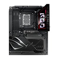


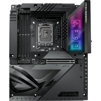
| Product Type | Motherboard |
| Form Factor | E-ATX (305 mm x 244 mm) |
| Weight | Approx. 1.5 kg |
| Socket | LGA 1851 |
| Chipset | Intel Z890 |
| Memory Support | 4x DDR5 DIMM, up to 192GB |
| Expansion Slots | 2x PCIe 5.0 x16, 1x PCIe 4.0 x4 |
| Storage | 4x M.2 (PCIe 5.0/4.0), 4x SATA 6Gb/s |
| Networking | Intel 2.5Gb Ethernet, Wi-Fi 7, Bluetooth 5.4 |
| Audio | Realtek ALC4080 with Savitech SV3H712 AMP |
| USB Ports (Rear) | 2x USB4 Type-C, 2x USB 3.2 Gen2 Type-A, 4x USB 3.2 Gen1, 2x USB 2.0 |
| Power Connectors | 24-pin ATX, 2x 8-pin EPS12V |
| Cooling Headers | 1x CPU fan, 1x AIO pump, 4x chassis fan |
| RGB Headers | 3x Addressable Gen2, 1x Aura RGB (4-pin) |
| BIOS | UEFI AMI with BIOS Flashback |
| Operating System | Windows 11 / 10 (64-bit) |
| Cleaning Instructions | Use compressed air to remove dust. Avoid liquid cleaners. |
| Safety Precautions | Handle with anti-static wrist strap. Power off and unplug before installation. |
| Spare Parts | Not available as single components. Contact ASUS support for warranty replacement. |
| Warranty | 3 years limited warranty |
Frequently Asked Questions - ROG Maximus Z890 HERO BTF ASUS
User questions about ROG Maximus Z890 HERO BTF ASUS
0 question about this device. Answer the ones you know or ask your own.
Ask a new question about this device
Download the instructions for your Wall socket in PDF format for free! Find your manual ROG Maximus Z890 HERO BTF - ASUS and take your electronic device back in hand. On this page are published all the documents necessary for the use of your device. ROG Maximus Z890 HERO BTF by ASUS.
USER MANUAL ROG Maximus Z890 HERO BTF ASUS
The items labeled below correspond to the installation steps, for steps 1 4 11 12 and more information on the steps, please refer to the rest of the guide.
Top side

Bottom side
![graph TD A["ATX_PWR"] --> B["CPU_GPT CHA_FAN AIO_PUMP"] C["USB 5Gbps"] --> D["USG_E12"] E["USB 20Gbps"] --> F["U20G_C9"] G["USB 10Gbps"] --> H["12V_2X6"] I["SATA6G_4"] --> J["U10G_C4"] K["SATA6G_3"] --> L["SATA6G_2"] M["SATA6G_1"] --> N["F PANEL"] O["Chassis Fan"] --> P["W_PUMP+ CHA_FAN4"] Q["Front…](/content/2026/07/1496647/images/b6ae670a54ee91f7ca2ed2429200973f5ba674538f4f6069a9fbe54f667b8ad9.jpg)
1 Prepare the components
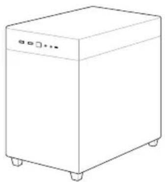
Chassis
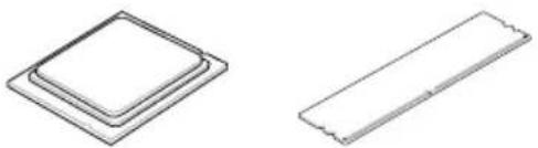
CPU Memory M.2 SSD


CPU Cooler

SATA device
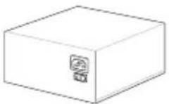
Power supply unit Graphics card

NOTE: The components listed above are recommendations, please prepare components according to your needs.
2 Install key components
- Install the CPU
Please scan for more information on CPU installation steps.


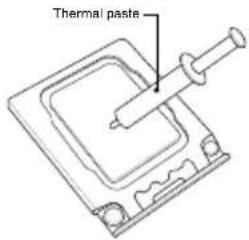

NOTE: Do not remove the PnP cap before the CPU is properly installed.
Please refer to the manual(s) for more information: Motherboard
• Install the Memory

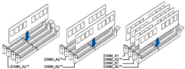
NOTE: Please refer to the manual(s) for more information: Motherboard
• Install the M.2 SSD
A

OPTIONAL

Install the bundled M.2 rubber when installing a single sided M.2 module
Make sure of the following:
• M.2 Q-Latch clicks and locks the M.2 SSD
- Secure the screw properly
- Insert the pin of the M.2 Anchor into the hole


B

OPTIONAL

Install the bundled M.2 rubber when installing a single sided M.2 module

Make sure the M.2 Q-Slide clicks and locks the M.2 SSD
Additional Information (on selected models)
M.2 Q-Release M.2 Q-Slide
Type-A Install
1

2
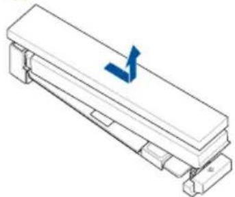

1

2

RemoveType-B

NOTE: Please refer to the manual(s) for more information: Motherboard
3 Install the cooling system
- Air Cooler


CPU_FAN / CPU_OPT
OR
- AIO Cooler


CPU_FAN / CPU_OPT (connect to radiator)
AIO_PUMP / W_PUMP (connect to pump)
NOTE: Please refer to these manual(s) for more information: Cooler Chassis
4 Install the motherboard into the chassis

For non pre-mounted I/O shield models only


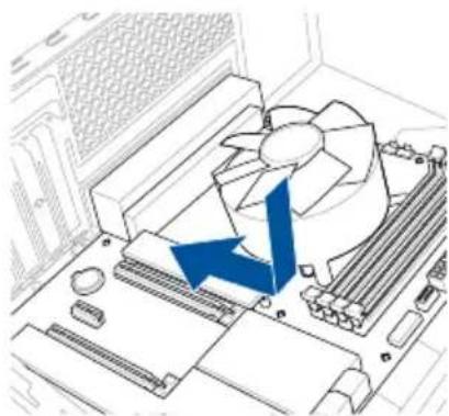


NOTE: Please refer to the manual(s) for more information: Motherboard Chassis
5 Connect to chassis fan and ARGB/RGB headers
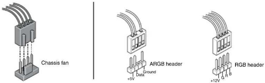
NOTE: Please refer to the manual(s) for more information: Motherboard Chassis Fan
6 Install and connect the power supply unit (PSU)


Make sure the PSU is secured to the chassis using screws, and that the chassis has proper airflow
NOTE: Input: AC 100\~240V, 6A/3A, 50/60Hz
Please refer to the manual(s) for more information: Chassis PSU
Connect cables from PSU
- Connect the power cables to the motherboard
A
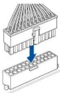
B


NOTE: Please refer to the manual(s) for more information: Motherboard PSU
7 Connect everything to the motherboard
- Front panel system header

- Front panel audio header

- USB connector/header
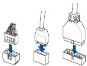
NOTE: Please refer to the manual(s) for more information:
Motherboard Chassis
Connect cables from PSU
- SATA

NOTE: Please refer to the manual(s) for more information: Motherboard
Connect cables from PSU
8 Install the graphics card

Please note that power connection is required for selected models.
NOTE: Ensure the all the golden fingers of the graphics card are seated securely in the slot.
Please refer to the manual(s) for more information:
Motherboard Chassis Graphics Card

9 Connect to the Internet via Ethernet/Wi-Fi antenna


NOTE: Please refer to the manual(s) for more information: Motherboard
10 Connect peripherals (monitor, keyboard, mouse, etc.)


11 Turn on the PSU and your PC


FAQ

NOTE: Please check the Q-LEDs or Q-LED Core on selected motherboards when powering on your PC for system status. If an error occurs, check if your CPU Fan header is properly connected; you can also scan the code or refer to the manual(s) for more information: Motherboard
12
Install the operating system and drivers

Driver and Utilities installation
Стъпки:
• To prevent electrical shock hazard, disconnect the power cable from the electrical outlet before relocating the system.
- When adding or removing devices to or from the system, ensure that the power cables for the devices are unplugged before the signal cables are connected. If possible, disconnect all power cables from the existing system before you add a device.
- Before connecting or removing signal cables from the motherboard, ensure that all power cables are unplugged.
- Seek professional assistance before using an adapter or extension cord. These devices could interrupt the grounding circuit.
- Ensure that your power supply is set to the correct voltage in your area. If you are not sure about the voltage of the electrical outlet you are using, contact your local power company.
• If the power supply is broken, do not try to fix it by yourself. Contact a qualified service technician or your retailer.
Operation safety
- Before installing the motherboard and adding devices on it, carefully read all the manuals that came with the package.
- Before using the product, ensure all cables are correctly connected and the power cables are not damaged. If you detect any damage, contact your dealer immediately.
- To avoid short circuits, keep paper clips, screws, and staples away from connectors, slots, sockets and circuitry.
- Avoid dust, humidity, and temperature extremes. Do not place the product in any area where it may become wet.
- Place the product on a stable surface.
- If you encounter technical problems with the product, contact a qualified service technician or your retailer.
- Your motherboard should only be used in environments with ambient temperatures between 10°C and 35°C .
Button/Coin Batteries Safety Information
- Remove and immediately recycle or dispose of used batteries according to local regulations and keep out of reach of children. Do not incinerate or dispose of batteries in household trash.
- If ingested or inserted inside any part of the body, call a local poison control center for treatment information. Even used batteries may cause serious injury or death.
- This product uses CR2032 type batteries with a nominal voltage of 3V.
- Do not attempt to recharge non-rechargeable batteries.
- Do not forcibly discharge, recharge, disassemble, heat above the battery manufacturer's specified temperature rating, or incinerate. Doing so may result in injury or chemical burns caused by venting, leakage, or explosion.
- This product contains non-replaceable batteries.
WARNING
- INGESTION HAZARD: This product contains a button cell or coin battery.
- DEATH or serious injury can occur if ingested.
- A swallowed button cell or coin battery can cause Internal Chemical Burns in as little as 2 hours.
- KEEP new and used batteries OUT OF REACH of CHILDREN.
- Seek immediate medical attention if a battery is suspected to be swallowed or inserted inside any part of the body.

General Notices
FCC Compliance Information
Responsible Party: Asus Computer International
Address: 48720 Kato Rd., Fremont, CA 94538, USA
Phone / Fax No: (510)739-3777 / (510)608-4555
This device complies with part 15 of the FCC Rules. Operation is subject to the following two conditions: (1) This device may not cause harmful interference, and (2) this device must accept any interference received, including interference that may cause undesired operation.
This equipment has been tested and found to comply with the limits for a Class B digital device, pursuant to part 15 of the FCC Rules. These limits are designed to provide reasonable protection against harmful interference in a residential installation. This equipment generates, uses and can radiate radio frequency energy and, if not installed and used in accordance with the instructions, may cause harmful interference to radio communications. However, there is no guarantee that interference will not occur in a particular installation. If this equipment does cause harmful interference to radio or television reception, which can be determined by turning the equipment off and on, the user is encouraged to try to correct the interference by one or more of the following measures:
- Reorient or relocate the receiving antenna.
- Increase the separation between the equipment and receiver.
- Connect the equipment into an outlet on a circuit different from that to which the receiver is connected.
- Consult the dealer or an experienced radio/TV technician for help.
HDMI Trademark Notice
The terms HDMI, HDMI High-Definition Multimedia Interface, HDMI trade dress and the HDMI Logos are trademarks or registered trademarks of HDMI Licensing Administrator, Inc.

HIGH-DEFINITION MULTIMEDIA INTERFACE
安全上のご注意
Australia statement notice
From 1 January 2012 updated warranties apply to all ASUS products, consistent with the Australian Consumer Law. For the latest product warranty details please visit https://www.asus.com/support/. Our goods come with guarantees that cannot be excluded under the Australian Consumer Law. You are entitled to a replacement or refund for a major failure and compensation for any other reasonably foreseeable loss or damage. You are also entitled to have the goods repaired or replaced if the goods fail to be of acceptable quality and the failure does not amount to a major failure.
If you require assistance please call ASUS Customer Service 1300 2787 88 or visit us at https://www.asus.com/support/.
Declaration of compliance for product environmental regulation
ASUS follows the green design concept to design and manufacture our products, and makes sure that each stage of the product life cycle of ASUS product is in line with global environmental regulations. In addition, ASUS disclose the relevant information based on regulation requirements.
Please refer to https://esg.asus.com/Compliance.htm for information disclosure based on regulation requirements ASUS is complied with:
EU REACH and Article 33
Complying with the REACH (Registration, Evaluation, Authorisation, and Restriction of Chemicals) regulatory framework, we published the chemical substances in our products at ASUS REACH website at https://esg.asus.com/Compliance.htm.
EU RoHS
This product complies with the EU RoHS Directive. For more details, see https://esg.asus.com/Compliance.htm.
India RoHS
This product complies with the “India E-Waste (Management) Rules, 2016” and prohibits use of lead, mercury, hexavalent chromium, polybrominated biphenyls (PBBs) and polybrominated diphenyl ethers (PBDEs) in concentrations exceeding 0.1% by weight in homogenous materials and 0.01% by weight in homogenous materials for cadmium, except for the exemptions listed in Schedule II of the Rule.
Vietnam RoHS
ASUS products sold in Vietnam, on or after September 23, 2011, meet the requirements of the Vietnam Circular 30/2011/TT-BCT.
ASUS recycling and takeback programs come from our commitment to the highest standards for protecting our environment. We believe in providing solutions for you to be able to responsibly recycle our products, batteries, other components as well as the packaging materials. Please go to https://esg.asus.com/en/Takeback.htm for detailed recycling information in different regions.

DO NOT throw the motherboard in municipal waste. This product has been designed to enable proper reuse of parts and recycling. This symbol of the crossed out wheeled bin indicates that the product (electrical and electronic equipment) should not be placed in municipal waste. Check local regulations for disposal of electronic products.

DO NOT throw the mercury-containing button cell battery in municipal waste. This symbol of the crossed out wheeled bin indicates that the battery should not be placed in municipal waste.
France sorting and recycling information

FR
Notices for Wi-Fi model
FCC RF Caution Statement
WARNING: Any changes or modifications not expressly approved by the party responsible for compliance could void your authority to operate the equipment.
FCC 5.925-7.125 GHz Caution Statement
Operation of transmitters in the 5.925-7.125 GHz band is prohibited for control of or communications with unmanned aircraft systems.
RF exposure warning
This equipment must be installed and operated in accordance with provided instructions and the antenna(s) used for this transmitter must be installed to provide a separation distance of at least 20 cm from all persons and must not be co-located or operating in conjunction with any other antenna or transmitter. End-users and installers must be provide with antenna installation instructions and transmitter operating conditions for satisfying RF exposure compliance.
Compliance Statement of Innovation, Science and Economic Development Canada (ISED)
This device complies with Innovation, Science and Economic Development Canada licence exempt RSS standard(s). Operation is subject to the following two conditions: (1) this device may not cause interference, and (2) this device must accept any interference, including interference that may cause undesired operation of the device. Operation in the band 5150–5250 MHz is only for indoor use to reduce the potential for harmful interference to co-channel mobile satellite systems.
CAN ICES-003(B)/NMB-003(B)
ISED 5.925-7.125 GHz Caution Statement (RLAN devices)
Devices shall not be used for control of or communications with unmanned aircraft systems.
KC: Korea Warning Statement
B급 기기 (가정용 방송통신기자재)
NCC: Wireless Statement
Japan RF Equipment Statement
屋外での使用について
Simplified UKCA Declaration of Conformity
ASUSTek Computer Inc. hereby declares that this device is in compliance with the essential requirements and other relevant provisions of The Radio Equipment Regulations 2017 (S.I. 2017/1206). Full text of UKCA declaration of conformity is available at https://www.asus.com/support/.
The WiFi operating in the band 5150-5350 MHz shall be restricted to indoor use for the country listed below:
UK
UKCA RF Output table (The Radio Equipment Regulations 2017) Model: BE200NGW
a. Low power indoor (LPI) Wi-Fi 5.945-6.425 GHz devices:
The device is restricted to indoor use only when operating in the 5925 to 6425 MHz frequency range in UK.
b. Very Low Power (VLP) Wi-Fi 5.945-6.425 GHz devices (portable devices):
The device is not permitted to be used on Unmanned Aircraft Systems (UAS) when operating in the 5925 to 6425 MHz frequency range in UK.
| Function Frequency Maximum Output Power EIRP (mW) | |
| WiFi | 2.4 - 2.4835 GHz < 100 |
| 5.15 - 5.35 GHz < 200 | |
| 5.47 - 5.725 GHz < 200 | |
| 5.725 - 5.875 GHz* < 25 | |
| 5.925 - 6.425 GHz < 200 | |
| Bluetooth | 2.4 - 2.4835 GHz < 100 |
Receiver Category 1
* Non-Intel modules: 5.725 - 5.85 GHz

Simplified EU Declaration of Conformity
Simplified EU Declaration of Conformity
ASUSTek Computer Inc. hereby declares that this device is in compliance with the essential requirements and other relevant provisions of Directive 2014/53/EU. Full text of EU declaration of conformity is available at
https://www.asus.com/support/.
The WiFi operating in the band 5150-5350 MHz shall be restricted to indoor use for countries listed in the table below:
a. Low power indoor (LPI) Wi-Fi 5.945-6.425 GHz devices:
The device is restricted to indoor use only when operating in the 5945 to 6425 MHz frequency range in Austria (AT), Belgium (BE), Bulgaria (BG), Cyprus (CY), Czech Republic (CZ), Estonia (EE), France (FR), Germany (DE), Iceland (IS), Ireland (IE), Latvia (LV), Luxembourg (LU), Netherlands (NL), Norway (NO), Romania (RO), Slovakia (SK), Slovenia (SI), Spain (ES), Switzerland (CH)
b. Very Low Power (VLP) Wi-Fi 5.945-6.425 GHz devices (portable devices):
The device is not permitted to be used on Unmanned Aircraft Systems (UAS) when operating in the 5945 to 6425 MHz frequency range in Austria (AT), Belgium (BE), Bulgaria (BG), Cyprus (CY), Czech Republic (CZ), Estonia (EE), France (FR), Germany (DE), Iceland (IS), Ireland (IE), Latvia (LV), Luxembourg (LU), Netherlands (NL), Norway (NO), Romania (RO), Slovakia (SK), Slovenia (SI), Spain (ES), Switzerland (CH).
https://www.asus.com/support/.
https://www.asus.com/support/
https://www.asus.com/support/.
Toliau nurodytose šalyse „WiFi“ ryšiu, veikiančiu 5 150–5 350 MHz dažnio juostoje, galima naudotis tik patalpose:
- ASUS offers a voluntary manufacturer's Commercial Guarantee.
• ASUS reserves the right to interpret the provisions of the ASUS Commercial Guarantee.
- This ASUS Commercial Guarantee is provided independently and in addition to the statutory Legal Guarantee and in no way affects or limits the rights under the Legal Guarantee.
For all the guarantee information, please visit https://www.asus.com/support.
F: Garantie ASUS
ASUSTeK Computer Inc
https://www.asus.com/vn/support
ASUS :HB
Warranty Card (Online)
Customer
Name:
Address:
Phone Number:
Email:
Product
Model Name:
Purchase Date: ____ / ____ / ____ (DD/MM/YYYY)
Serial Number:
Dealer
Name:
Address:
Phone Number:
Stamp:

ASUS contact information
ASUSTeK COMPUTER INC.
Address: 1F., No. 15, Lide Rd., Beitou Dist., Taipei City 112
https://qr.asus.com/ProductSafety
ASUS COMPUTER INTERNATIONAL (America)
Address: 48720 Kato Rd., Fremont, CA 94538, USA
ASUS COMPUTER GmbH (Germany and Austria)
Address: Harkortstrasse 21-23, 40880 Ratingen, Germany
ASUSTeK (UK) LIMITED
Address: 1st Floor, Sackville House, 143-149 Fenchurch Street, London, EC3M 6BL, England, United Kingdom
ASUS GLOBAL PTE. LTD.
Address: 10 Changi Business Park Central 2 #02-01 Hansapoint Singapore 486030
https://qr.asus.com/ProductSafety
Service and Support
Visit our multi-language website at https://www.asus.com/support.

Product Register
Log in and register your device for better product support.


REPUBLIC OF GAMERS
- PREPARE THE COMPONENTS
- INSTALL KEY COMPONENTS
- ADDITIONAL INFORMATION (ON SELECTED MODELS)
- INSTALL THE COOLING SYSTEM
- OR
- INSTALL THE MOTHERBOARD INTO THE CHASSIS
- CONNECT TO CHASSIS FAN AND ARGB/RGB HEADERS
- INSTALL AND CONNECT THE POWER SUPPLY UNIT (PSU)
- CONNECT CABLES FROM PSU
- CONNECT EVERYTHING TO THE MOTHERBOARD
- INSTALL THE GRAPHICS CARD
- CONNECT TO THE INTERNET VIA ETHERNET/WI-FI ANTENNA
- CONNECT PERIPHERALS (MONITOR, KEYBOARD, MOUSE, ETC.)
- TURN ON THE PSU AND YOUR PC
- INSTALL THE OPERATING SYSTEM AND DRIVERS
- СТЪПКИ
- OPERATION SAFETY
- BUTTON/COIN BATTERIES SAFETY INFORMATION
- WARNING
- GENERAL NOTICES
- FCC COMPLIANCE INFORMATION
- HDMI TRADEMARK NOTICE
- 安全上のご注意
- AUSTRALIA STATEMENT NOTICE
- DECLARATION OF COMPLIANCE FOR PRODUCT ENVIRONMENTAL REGULATION
- EU REACH AND ARTICLE
- EU ROHS
- INDIA ROHS
- VIETNAM ROHS
- FRANCE SORTING AND RECYCLING INFORMATION
- FR
- NOTICES FOR WI-FI MODEL
- FCC RF CAUTION STATEMENT
- FCC 5.925-7.125 GHZ CAUTION STATEMENT
- RF EXPOSURE WARNING
- COMPLIANCE STATEMENT OF INNOVATION, SCIENCE AND ECONOMIC DEVELOPMENT CANADA (ISED)
- ISED 5.925-7.125 GHZ CAUTION STATEMENT (RLAN DEVICES)
- KC: KOREA WARNING STATEMENT
- NCC: WIRELESS STATEMENT
- JAPAN RF EQUIPMENT STATEMENT
- 屋外での使用について
- SIMPLIFIED UKCA DECLARATION OF CONFORMITY
- UK
- UKCA RF OUTPUT TABLE (THE RADIO EQUIPMENT REGULATIONS 2017) MODEL: BE200NGW
- SIMPLIFIED EU DECLARATION OF CONFORMITY
- HTTPS://WWW.ASUS.COM/SUPPORT
- F: GARANTIE ASUS
- ASUS CONTACT INFORMATION
- SERVICE AND SUPPORT
- PRODUCT REGISTER
Brand : ASUS
Model : ROG Maximus Z890 HERO BTF
Category : Wall socket