
BVM 240 24CC - Brush cutter MCCULLOCH - Free user manual and instructions
Find the device manual for free BVM 240 24CC MCCULLOCH in PDF.
| Product type | Petrol brushcutter |
| Brand | McCulloch |
| Model | BVM 240 24CC |
| Displacement | 24 cm³ |
| Engine | 2-stroke, air-cooled |
| Power | 0.9 kW (1.2 hp) |
| Fuel | Mixed petrol (50:1) |
| Fuel tank capacity | 0.5 L |
| Cutting width | 40 cm |
| Max cutting diameter | 25 mm |
| Blade type | 3-tooth blade or nylon line head (compatible) |
| Rotation speed | 7000 rpm |
| Dimensions (L x W x H) | 180 x 25 x 30 cm |
| Weight (without fuel) | 5.2 kg |
| Sound level (at ear) | 96 dB(A) |
| Vibration (handle) | 7.5 m/s² |
| Handle type | Dual-handle (U-shaped handle) |
| Harness | Single strap harness included |
| Recommended maintenance | Clean air filter after each use, drain fuel at end of season |
| Safety | Blade guard, quick engine stop, safety trigger |
| Spare parts available | Spark plug, air filter, blade, line head (McCulloch references) |
| Repairability | Repairability index 7.2/10 (estimated) |
Frequently Asked Questions - BVM 240 24CC MCCULLOCH
User questions about BVM 240 24CC MCCULLOCH
0 question about this device. Answer the ones you know or ask your own.
Ask a new question about this device
Download the instructions for your Brush cutter in PDF format for free! Find your manual BVM 240 24CC - MCCULLOCH and take your electronic device back in hand. On this page are published all the documents necessary for the use of your device. BVM 240 24CC by MCCULLOCH.
USER MANUAL BVM 240 24CC MCCULLOCH
IMPORTANT INFORMATION: Please read these instructions carefully and make sure you understand them before using this unit. Retain these instructions for future reference.
FR
MANUEL D'INSTRUCTIONS
WARNING! This blower can be dangerous! Careless or improper use can cause serious or even fatal injury.
Read and understand the instruction manual before using the blower.
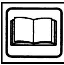
WARNING! Be sure the bottom cover is secured or the vacuum tube is properly installed. Avoid the impeller blade with your hand or any foreign object.
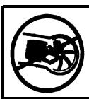
Instructions on how to open vacuum inlet cover.
Use unleaded or quality leaded petrol and two stroke oil.

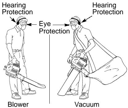
Always wear eye and ear protection.

Fast throttle

Slow idle
SAFETY RULES

WARNING: Failure to follow all
Safety Rules and Precautions can result in serious injury.
KNOW YOUR UNIT
- Read your instruction manual carefully until you completely understand and can follow all warnings and safety rules before operating the unit.
- Restrict unit to users who understand and will follow all warnings and safety rules in this manual.

WARNING: Inspect area before startunit. Remove all debris and hard objects, as rocks, glass, wire, etc. that can ricoct, be thrown, or otherwise cause injury or damage during operation.
Use your unit as a blower for:
- Sweeping debris or grass clippings from driveways, sidewalks, patios, etc.
- Blowing grass clippings, straw, or leaves into piles, around joints, or between bricks.
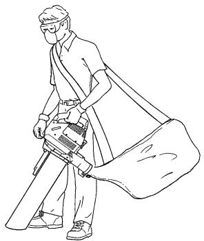
Use your unit as a vacuum for:
- Picking up dry material such as leaves, grass, small twigs, and bits of paper.
- For best results during vacuum use, operate your unit at high speed.
- Move slowly back and forth over the material as you vacuum. Avoid forcing the unit into a pile of debris as this can clog the unit.
- Keep the vacuum tube about an inch above the ground for best results.
PLAN AHEAD
Always wear eye and ear protection when operating, servicing, or performing maintenance on unit. Wearing eye protection will help to prevent rocks or debris from being blown or ricocheting into eyes and face which can result in blindness and/or serious injury. Eye protection should be marked Z87.
Always wear foot protection. Do not go barefoot or wear sandals.
Always wear respirator or face mask when working with unit in dusty environments.
- Secure hair above shoulder length. Secure or remove jewelry, loose clothing, or clothing with loosely hanging straps, ties, tassels, etc. They can be caught in moving parts.
- Do not operate unit when you are tired, ill, upset, or if you are under the influence of alcohol, drugs, or medication.
- Keep children, bystanders, and animals away from work area a minimum of 10 meters when starting or operating unit. Do not point blower nozzle in the direction of people or pets.
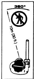
The operator of the machine must insure that no one comes within a 10 meter radius while working. When several operators are working within the same area, a safety distance of at least 10 meters must be observed.
Sound power
WARNING!
The blower can throw objects violently.
-You can be blinded or injured.
-Always wear eye protection.

HANDLE FUEL WITH CAUTION
- Eliminate all sources of sparks or flame (including smoking, open flames, or work that can cause sparks) in the areas where fuel is mixed, poured, or stored.
- Mix and pour fuel in an outdoor area; store fuel in a cool, dry, well ventilated place; use an approved, marked container for all fuel purposes.
- Do not smoke while handling fuel or while operating the unit.
- Make sure the unit is properly assembled and in good operating condition.
- Do not fill fuel tank while engine is hot or running.
- Avoid spilling fuel or oil. Wipe up fuel spills before starting engine.
- Move at least 3 meters away from fuel and fueling site before starting engine.
Always store petrol in a container approved for flammable liquids.
OPERATE YOUR UNIT SAFELY
WARNING: Stop the engine before opening the vacuum inlet door. The engine must be stopped and the impeller blades no longer turning to avoid serious injury from the rotating blades.
- Inspect unit before each use for worn, loose, missing, or damaged parts. Do not use until unit is in proper working order.
- Keep outside surfaces free of oil and fuel.
- Never start or run engine inside a closed room or building. Breathing exhaust fumes can kill.
- To avoid static electricity shock, do not wear rubber gloves or any other insulated gloves while operating unit.
- Do not set unit on any surface except a clean, hard area while engine is running. Debris such as gravel, sand, dust, grass, etc. could be picked up by the air intake and thrown out through discharge opening, damaging unit, property, or causing serious injury to bystanders or operator.
- Avoid dangerous environments. Do not use in unventilated areas or where explosive vapors or carbon monoxide build up could be present.
- Do not overreach or use from unstable surfaces such as ladders, trees, steep slopes, rooftops, etc. Keep firm footing and balance at all times.
- Never place objects inside the blower tubes; always direct the blowing debris away from people, animals, glass, and solid objects such
as trees, automobiles, walls, etc. The force of air can cause rocks, dirt, or sticks to be thrown or to ricochet which can hurt people or animals, break glass, or cause other damage.
- Never run unit without the proper equipment attached. When using your unit as a blower, always install blower tubes. When using your unit as a vacuum, always install vacuum tubes and vacuum bag assembly. Make sure vacuum bag assembly is completely zipped.
- Check air intake opening, blower tubes, vacuum tubes, and elbow tube frequently, always with engine stopped and spark plug disconnected. Keep vents and discharge tubes free of debris which can accumulate and restrict proper air flow.
- Never place any object in the air intake opening as this could restrict proper air flow and cause damage to the unit.
- Never use for spreading chemicals, fertilizers, or other substances which may contain toxic materials.
- To avoid spreading fire, do not use near leaf or brush fires, fireplaces, barbecue pits, ashtrays, etc.
- Use only for jobs explained in this manual.
MAINTAIN YOUR UNIT PROPERLY
- Have all maintenance other than the recommended procedures described in the instruction manual performed by an authorized service dealer.
- Disconnect spark plug before performing maintenance except for carburetor adjustments.
- Use only recommended McCulloch® replacement parts; use of any other parts may void your warranty and cause damage to your unit.
- Empty fuel tank before storing the unit. Use up fuel left in carburetor by starting engine and letting it run until it stops.
- Do not use any accessory or attachment other than those recommended by manufacturer for use with your unit.
- Do not store the unit or fuel in a closed area where fuel vapors can reach sparks or an open flame from hot water heaters, electric motors or switches, furnaces, etc.
- Store in a dry area out of reach of children.
SAFETY NOTICE: Exposure to vibrations through prolonged use of gasoline powered hand tools could cause blood vessel or nerve damage in the fingers, hands, and joints of people prone to circulation disorders or abnormal swelling. Prolonged use in cold weather has been linked to blood vessel damage in otherwise healthy people. If symptoms occur such as numbness, pain, loss of strength, change in skin color or texture, or loss of feeling in the fingers, hands, or joints, discontinue the use of this tool and seek medical attention. An antivibration system does not guarantee the avoidance of these problems. Users who operate power tools on a continual and regular basis must monitor closely their physical condition and the condition of this tool.
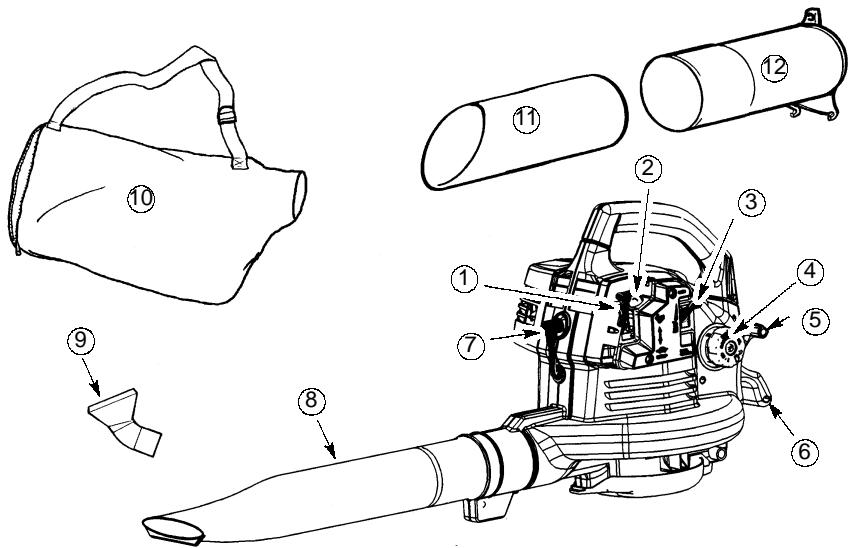
WHAT IS WHAT?
WHAT IS WHAT?
- Throttle Lever
- Primer button
- Choke lever
- Fuel cap
- Starter rope
- Rear handle
-
Spark plug
-
Blower tube
- Elbow tube
- Vacuum bag
- Lower vacuum tube
- Upper vacuum tube
- Instruction manual
ASSEMBLY
CARTON CONTENTS
Check carton contents against the following list.
Blower
- Blower tube
- Upper vacuum tube
- Lower vacuum tube
- Elbow tube
Vacuum bag
NOTE: It is normal for the fuel filter to rattle in the empty fuel tank.
ASSEMBLY

WARNING: Stop engine and be sure impeller blades have stopped turning before opening the vacuum inlet door or attempting to insert or remove the vacuum or over tubes. The rotating blades can cause serious injury. Always disconnect the sparks before performing maintenance or accessing movable parts.

WARNING: If received assembled, eat all steps to ensure your unit is properly assembled and all fasteners are secure. Folicall safety information in the manual and on a unit.
- A standard screwdriver is required for assembly.
BLOWER TUBE ASSEMBLY
- Align the rib on the blower tube with the groove in the blower outlet; slide the tube into place.
NOTE: Knob must be loose enough to allow blower tube to be inserted in blower outlet. Loosen knob by turning counterclockwise.
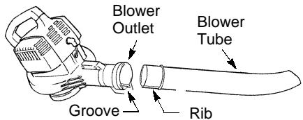
- Secure the tube by turning the knob clockwise.
- To remove the tube, turn the knob counterclockwise to loosen the tube; remove the tube.
VACUUM BAG ASSEMBLY
- Open the zipper on the vacuum bag and insert the elbow tube.
- Push the small end of the elbow tube through the small opening in the bag.
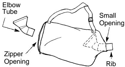
NOTE: Make sure edge of the small opening is flush against the flared area of the elbow tube, and the rib on the elbow tube is on the bottom.
- Close the zipper on the bag. Make sure the zipper is closed completely.
- Remove blower tube from engine.
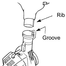
- Insert the elbow tube into the blower outlet. Make sure elbow tube rib is aligned with the blower outlet groove.
- Turn knob clockwise to secure elbow tube.
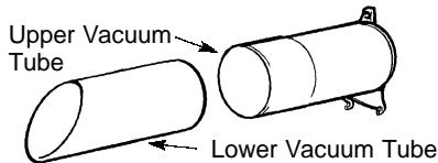
VACUUM TUBE ASSEMBLY
- Align the lower vacuum tube as shown. Push lower vacuum tube into upper vacuum tube.
- Insert the tip of a screwdriver into the latch area of the vacuum inlet.
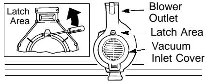
-
Gently tilt the handle of the screwdriver toward the back of the unit to release the latch while pulling up on the vacuum inlet cover with your other hand.
-
Hold the vacuum inlet cover open until upper vacuum tube is installed.
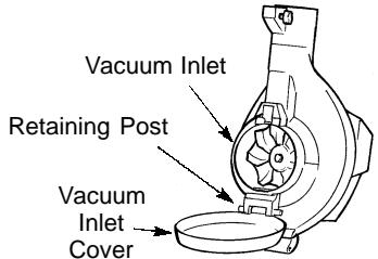
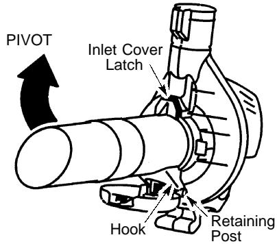
- Place the hooks of the upper vacuum tube on the retaining posts of the unit.
- Pivot the tube until it is secured to the blower unit by the vacuum inlet latch.
HOW TO CONVERT UNIT FROM VACUUM USE TO BLOWER USE
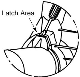
- Remove the vacuum tubes by inserting the tip of a screwdriver into the latch area of the vacuum inlet.
- Gently tilt handle of screwdriver toward the back of the unit to release the latch while pulling up on the upper vacuum tube with your other hand.
- Remove the vacuum bag.
- Close the vacuum inlet cover and make sure it is latched closed.
- Reinstall the blower tube (see BLOWER TUBE ASSEMBLY).
SHOULDER STRAP ADJUSTMENT (for vacuum use only)
- Hold the unit as shown with the muffler side facing away from your body and clothes.
- Pass the shoulder strap over your head and onto your right shoulder.
- Extend your left arm toward the rear of the vacuum bag.
- Adjust shoulder strap until the vacuum bag/shoulder strap seam lies between your thumb and index finger.
- Make sure air flows freely from the elbow tube into bag. If bag is kinked, the unit will not operate properly.
OPERATION
OPERATING POSITION
OPERATING TIPS
- While vacuuming or blowing debris, hold the unit with the muffler side facing away from your body and clothes (see OPERATING POSITION).
- To reduce the risk of hearing loss associated with sound level(s), hearing protection is required.
- To reduce the risk of injury associated with contacting rotating parts, stop the engine before installing or removing attachments. Do not operate without guard(s) in place.
- Operate power equipment only at reasonable hours-not early in the morning or late at night when people might be disturbed. Comply with times listed in local ordinances. Usual recommendations are 9:00 a.m. to 5:00 p.m., Monday though Saturday.
- To reduce noise levels, limit the number of pieces of equipment used at any one time.
- To reduce noise levels, operate power blowers at the lowest possible throttle speed to do the job.
- Use rakes and brooms to loosen debris before blowing.
- In dusty conditions, slightly dampen surfaces or use a mister attachment when water is available.
-
Conserve water by using power blowers instead of hoses for many lawn and garden applications, including areas such as gutters, screens, patios, grills, porches, and gardens.
-
Watch out for children, pets, open windows, or freshly washed cars. Blow debris away safely.
- Use the full blower nozzle extension so the air stream can work close to the ground.
After using blowers and other equipment, CLEAN UP! Dispos of debris in trash receptacles.
BEFORE STARTING ENGINE
WARNING: Be sure to read the fuel information in the safety rules before you begin. If you do not understand the safety rules, do not attempt to fuel your unit. Contact an authorized service dealer.
FUELING ENGINE
WARNING: Remove fuel cap slowly when refueling.
This engine is certified to operate on unleaded petrol. Before operation, petrol must be mixed with a good quality 2-cycle air-cooled engine oil. We recommend McCulloch® brand oil mixed at a ratio of 40:1 (2.5%). A 40:1 ratio is obtained by mixing 5 liters of unleaded petrol with 0,125 liter of oil. When mixing fuel, follow the instructions printed on the container. Always read and follow the safety rules before fueling your unit.
IMPORTANT
Experience indicates that alcohol blended fuels (called gasohol or using ethanol or methanol) can attract moisture which leads to separation and formation of acids during storage. Acidic gas can damage the fuel system of an engine while in storage. To avoid engine problems, empty the fuel system before storage for 30 days or longer. Drain the gas tank, start the engine and let it run until the fuel lines and carburetor are empty. Use fresh fuel next season. Never use engine or carburetor cleaner products in the fuel tank or permanent damage may occur.
STOPPING YOUR ENGINE
- To stop the engine, move the throttle lever to the STOP position.
BEFORE STARTING THE ENGINE
WARNING: You MUST make sure the tubes are secure before using the unit.
- Fuel engine. Move at least 3 meters away from the fueling site.
- Hold the unit in the starting position as shown. Make sure the blower end is directed away from people, animals, glass, and solid objects.
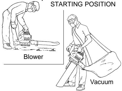
WARNING: When starting engine, hold the unit as illustrated. Do not set unit on any surface except a clean, hard area when starting engine or while engine is running. Debris such as gravel, sand, dust, grass, etc. could be picked up by the air intake and thrown out through the discharge opening, damaging the unit or property, or causing serious injury to bystanders or the operator.
STARTING A COLD ENGINE (or a warm engine after running out of fuel)
- Move throttle lever to the position.
- Move choke lever to the FULL CHOKE position.
- Slowly press the primer bulb 8 times. Throttle Lever Primer Button
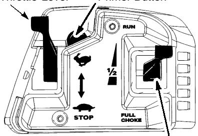
Choke Lever
- Pull starter rope sharply until engine attempts to run, but no more than 5 pulls (below 0^ C, 8 pulls).
NOTE: If engine attempts to start before the 5^th pull, go to next step immediately. - Move the choke lever to the HALF CHOKE position.
- Pull the starter rope sharply until the engine runs, but no more than 5 pulls (below 0^ C, 10 pulls).
- Run engine for 5 seconds, then move choke lever to the RUN position.
- Allow the unit to run for 30 more seconds at the RUN position before moving the throttle lever to the position.
If engine has not started after 5 pulls (at HALF CHOKE), repeat STARTING A COLD ENGINE procedure. If engine still does not start, proceed to STARTING A FLOODED ENGINE.
9. To stop the engine, move the throttle lever to the STOP position.
STARTING A WARM ENGINE
- Move throttle lever to the position.
- Pull starter rope sharply until engine runs but no more than 5 pulls.
STARTING A FLOODED ENGINE
NOTE: If engine has not started, pull starter rope 5 more pulls. If engine still does not run, it is probably flooded.
3. To stop the engine, move the throttle lever to the STOP position.
Flooded engines can be started by placing the choke lever in the RUN position. Move throttle lever to the fast position ; then, pull rope until engine starts. After engine starts, move the throttle lever to the slow position to allow engine to idle.
Starting could require pulling the starter rope many times depending on how badly the unit is flooded.
If unit still doesn't start, refer to the TROUBLESHOOTING TABLE or contact an authorized service dealer.
WARNING: Avoid touching muffler unless engine and muffler are cold. A hot muffler can cause serious burns.
WARNING: Disconnect the spark plug before performing maintenance except for carburetor adjustments.
CHECK FOR LOOSE FASTENERS AND PARTS
- Spark Plug Boot
Air Filter
Housing Screws
CHECK FOR DAMAGED OR WORN PARTS
Contact an authorized service dealer for replacement of damaged or worn parts.
- Throttle Lever - Ensure throttle lever functions properly by moving the throttle lever to the STOP position. Make sure engine stops; then restart engine and continue.
- Fuel Tank. Discontinue use of unit if fuel tank is damaged or leaks.
Vacuum Bag - Discontinue use of vacuum bag if it is torn or damaged.
INSPECT AND CLEAN UNIT & LABELS
- After each use, inspect complete unit for loose or damaged parts. Clean the unit and decals using a damp cloth with a mild detergent.
- Wipe off unit with a clean dry cloth.
CLEAN AIR FILTER
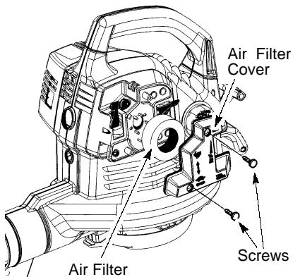
Cleaning the air filter:
A dirty air filter decreases engine performance and increases fuel consumption and harmful emissions. Always clean after every 5 hours of operation or yearly, whichever comes first.
- Clean the cover and the area around it to keep debris from falling into the carburetor chamber when the cover is removed.
- Remove parts as illustrated.
NOTE: Do not clean filter in gasoline or other flammable solvent. Doing so can
create a fire hazard or produce harmful evaporative emissions.
- Wash the filter in soap and water.
- Allow filter to dry.
- Apply a few drops of oil to the filter; squeeze filter to distribute oil.
- Replace parts
REPLACE SPARK PLUG
Replace spark plug each year to ensure the engine starts easier and runs better. Set spark plug gap at 0.025 inch. Ignition timing is fixed, nonadjustable.
- Twist, then pull off spark plug boot.
- Remove spark plug from cylinder and discard.
- Replace with Champion RCJ-6Y spark plug and tighten securely with a 19 mm socket wrench.
- Reinstall the spark plug boot.
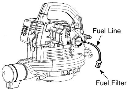
REPLACE FUEL FILTER
To replace fuel filter, drain unit by running it dry of fuel, then remove fuel cap/retainer assembly from tank. Pull filter from tank and remove it from fuel line. Install new fuel filter on fuel line; reinstall parts.
CHECK MUFFLER MOUNTING SCREWS
Once each year, ensure muffler mounting screws are secure and tightened properly to prevent damage.
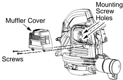
- Loosen and remove the 2 screws from the muffler cover.
- Remove the muffler cover.
- Tighten the 2 muffler mounting screws securely.
- Reinstall muffler cover and 2 screws. Tighten securely.
INSPECT MUFFLER AND SPARK ARRESTING SCREEN
As the unit is used, carbon deposits build up on the muffler and spark arresting screen, and must be removed to avoid creating a fire hazard or affecting engine performance.
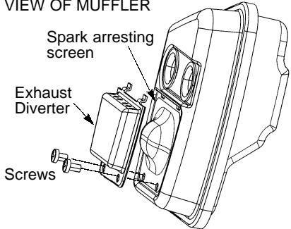
VIEW OF MUFFLER
Replace the spark arresting screen every 25 hours of operation or if any damage or breaks in the screen are noted.
NOTE: Do not attempt to clean the spark arresting screen.
- Loosen and remove the 2 screws from the muffler cover. Remove the muffler cover.
- Loosen and remove both screws from the exhaust diverter.
- Remove the exhaust diverter and spark arresting screen.
- Install new spark arresting screen.
- Reinstall exhaust diverter and both screws. Tighten screws securely.
- Reinstall muffler cover and 2 screws.
NOTE: If any part of the muffler is cracked, broken or damaged, we recommend that the muffler be replaced.
CARBURETOR ADJUSTMENTS
There is no screw for idle adjustment on your blower. The throttle lever is used to control engine speed. The throttle lever can be placed in one of four positions: STOP, IDLE or , FULL THROTTLE or , and one intermittent position. If your engine will not run properly or you require further assistance, contact an authorized service dealer.
STORAGE

WARNING: Prepare unit for storage at
end of season or if it will not be used for 30 days or more.
- Allow engine to cool, and secure the unit before storing or transporting.
- Store unit and fuel in a well ventilated area where fuel vapors cannot reach sparks or open flames from water heaters, electric motors or switches, furnaces, etc.
- Store unit with all guards in place. Position unit so that any sharp object cannot accidentally cause injury.
- Store unit and fuel well out of the reach of children.
EXTERNAL SURFACES
- If your unit is to be stored for a period of time, clean it thoroughly before storage. Store in a clean dry area.
- Lightly oil external metal surfaces.
INTERNAL ENGINE
- Remove spark plug and pour 1 teaspoon of 2-cycle engine oil (air cooled) through the spark plug opening. Slowly pull the starter rope 8 to 10 times to distribute oil.
- Replace spark plug with new one of recommended type and heat range.
Clean air filter. - Check entire unit for loose screws, nuts, and bolts. Replace any damaged, broken, or worn parts.
- Start each season using only fresh fuel having the proper gasoline to oil ratio.
OTHER
- Do not store gasoline from one season to another.
- Replace your gasoline can if it starts to rust.
WARNING: Always stop unit and disconnect spark plug before performing any of the recommended remedies below other than remedies that require operation of the unit.
TROUBLESHOOTING TABLE
| TROUBLE | CAUSE | REMEDY |
| Engine will not start. | 1. Engine flooded. 2. Fuel tank empty. 3. Spark plug not firing. 4. Fuel not reaching carburetor. 5. Compression low. | 1. See “Starting Instructions.” 2. Fill tank with correct fuel mixture. 3. Install new spark plug. 4. Check for dirty fuel filter; replace. Check for kinked or split fuel line; repair or replace. 5. Contact an authorized service dealer. |
| Engine will not idle properly. | 1. Fuel not reaching carburetor. 2. Carburetor requires adjustment. 3. Crankshaft seals worn. 4. Compression low. | 1. Check for dirty fuel filter; replace. Check for kinked or split fuel line; repair or replace. 2. Contact an authorized service dealer. 3. Contact an authorized service dealer. 4. Contact an authorized service dealer. |
| Engine will not accelerate, lacks power, or dies under a load. | 1. Air filter dirty. 2. Fuel not reaching carburetor. 3. Spark plug fouled. 4. Spark arresting screen clogged. 5. Carburetor requires adjustment. 6. Carbon build up. 7. Compression low. | 1. Clean or replace air filter. 2. Check for dirty fuel filter; replace. Check for kinked or split fuel line; repair or replace. 3. Clean or replace spark plug; re-gap. 4. Replace screen. 5. Contact an authorized service dealer. 6. Contact an authorized service dealer. 7. Contact an authorized service dealer. |
| Engine smokes excessively. | 1. Choke partially on. 2. Fuel mixture incorrect. 3. Air filter dirty. 4. Carburetor requires adjustment. | 1. Adjust choke. 2. Empty fuel tank and refill with correct fuel mixture. 3. Clean or replace air filter. 4. Contact an authorized service dealer. |
| Engine runs hot. | 1. Fuel mixture incorrect. 2. Spark plug incorrect. 3. Carburetor requires adjustment. 4. Carbon build up. | 1. See “Fueling Your Unit.” 2. Replace with correct spark plug. 3. Contact an authorized service dealer. 4. Contact an authorized service dealer. |
DECLARATION OF CONFORMITY relating to 2000/14/EC
EU Declaration of Conformity relating to 2000/14/EC
We, Poulan/Weed Eater Division, Electrolux Home Products, Inc., Texarkana, TX, 75501, USA, Tel.: +1 903 223 4100, declare under sole responsibility that the McCulloch model BVM 240 leaf blower was assessed in accordance with Annex V of the DIRECTIVE and from serial numbers 2002-137N00001 and onwards, conforms to the provisions of the DIRECTIVE. The nominal air flow is 0.142m^3/s . The measured sound power is 107 dB and the guaranteed sound power is 112 dB.
Texarkana 02-05-17

Michael S. Bounds, Director Product Safety and Standards
DECLARATION OF CONFORMITY
relating to 98/37/EC
EU Declaration of Conformity (Directive 98/37/EC, Annex II, A) (Only applies to Europe)
We, Poulan/Weed Eater Division, Electrolux Home Products, Inc, Texarkana, TX, 75501, USA, Tel: +1 903 223 4100, declare under sole responsibility that the McCulloch model BVM 240 leaf blower from serial numbers 2002-137N00001 and onwards, follows the provisions of the DIRECTIVES: 98/37/EC (machinery) and 89/336/EEC (electromagnetic compatibility), including amendments and is in conformity with the following standards: EN 292-2 and CISPR 12.
SMP, The Swedish Machinery Testing Institute, Fyrisborgsgatan 3 S-754 50 Uppsala, Sweden, has carried out voluntary type approval. The certificate(s) are numbered: SEC/97/475.
Texarkana 02-05-17

Michael S. Bounds, Director
Safety and Standards
TECHNICAL DATA
| MODEL: BVM 240 | |
| ENGINE | |
| Engine displacement | 25 cm3 |
| Maximum Engine Power, according to ISO 8893 | 0,71 kW |
| Rotational Speeds | |
| Idle Speed +/- 400 | 3700 rpm |
| Maximum recommended output shaft speed | 8400 rpm |
| Engine speed at maximum recommended output shaft speed | 8400 rpm |
| MASS | |
| BLOWER | 4,8 kg |
| VACUUM | 5,5 kg |
| VOLUME | |
| Fuel tank | 360 cm3 |
| SOUND PRESSURE LEVEL | |
| According to prEN 31806 | |
| BLOWER | |
| Idling: | 80,9 dB(A) |
| Racing | 95,2 dB(A) |
| VACUUM | |
| Idling: | 89,6 dB(A) |
| Racing | 100,0 dB(A) |
| SOUND POWER LEVEL | |
| According to ISO/CD 10884 | |
| BLOWER: | 106 dB(A) |
| VACUUM: | 107 dB(A) |
| VIBRATIONS | |
| According to ISO 7916 | |
| BLOWER | |
| Idling: | Top 12,1 m/s2 |
| Racing: | Top 16,0 m/s2 |
| VACUUM | |
| Idling: | Top 10,9 m/s2 |
| Racing: | Top 16,6 m/s2 |
YEAR OF CONSTRUCTION:
MANUFACTURER'S ADDRESS:
2003
EOPI Italy
Via Como 72
Valmadrera, Lecco
ITALY I-23868