
RL34T662ESA - Refrigerator SAMSUNG - Free user manual and instructions

Find the device manual for free RL34T662ESA SAMSUNG in PDF.
SAMSUNG RL34T662ESA - Refrigerator
📄 208 pages English EN Download 💬 AI Question 10 questions ⚙️ Specs
Notice SAMSUNG RL34T662ESA - page 3
Pick your language and provide your email: we'll send you a specifically translated version.
Product typeRefrigerator
BrandSamsung
ModelRL34T662ESA
Energy efficiency classA+++
Total net volume340 L
Dimensions (H × W × D)1780 × 595 × 650 mm
Net weight70 kg
Power supply220-240 V, 50 Hz
Refrigerant gas typeR600a
Noise level35 dB
Cooling functionMulti-flow, ventilated cold
Interior lightingLED
Water dispenserIntegrated
Bottle shelfYes (removable)
Door bins4 (adjustable)
Vegetable drawer2 with humidity control
FreezerBottom compartment, 100 L
Power failure autonomy12 hours
Ambient operating temperature10 °C to 43 °C
Maintenance and cleaningClean regularly with a soft cloth and soapy water; defrost if necessary
SafetyChild lock, open door alarm
Spare partsAvailable via Samsung customer service or authorized dealers

Frequently Asked Questions - RL34T662ESA SAMSUNG

What is the ideal temperature for the refrigerator and freezer?
The recommended temperature for the refrigerator is +4°C and for the freezer is -18°C. These temperatures ensure optimal food preservation.
How to adjust the temperature of the refrigerator?
Use the keys or the adjustment button inside the refrigerator compartment. Digital models display the temperature; press the arrows to adjust, wait 24 hours for stabilization.
What to do if the alarm light turns on?
An alarm light may indicate a poorly closed door, too high a temperature, or a defect. Check the door closure, do not open too often and allow air circulation.
How to clean the interior of the refrigerator?
Unplug the appliance, remove shelves and bins, clean with a soft cloth and warm soapy water, rinse and dry. Never use abrasive products.
Why is the appliance making noise?
Noises are normal: the compressor, refrigerant gas circulation, and fans. Clicking or humming sounds are common. If the noise becomes abnormal, check stability or call a technician.
How to change the refrigerator light bulb?
Unplug the appliance, remove the light cover, unscrew the defective bulb and replace it with a bulb of the same type (LED or incandescent depending on the model). Note: some models have non-replaceable LED lighting.
The water dispenser is not working, what to do?
Check the water supply, the filter (if clogged), defrost if necessary, and make sure the freezer temperature is low enough. If the problem persists, contact technical service.
How to interpret error codes on the screen?
Codes like 'Er' (Error) or 'CF' (Control Failure) indicate a malfunction. Consult the manual for the specific code: 'Er-01' may be a sensor, 'CF' a board problem. Reset the appliance by unplugging it for 5 minutes.
Where to find spare parts for this refrigerator?
Parts are available on the Samsung website (service.parts) or from authorized dealers. Use the model number (RL34T662ESA) to identify references.
What is the energy impact of this model?
Class A+++ guarantees a consumption of about 150 kWh/year. To optimize, place the appliance in a ventilated area, away from heat sources, and do not overload compartments.

User questions about RL34T662ESA SAMSUNG

0 question about this device. Answer the ones you know or ask your own.

Ask a new question about this device

Your email remains private: it is only used to notify you if someone answers your question.

No questions yet. Be the first to ask one.

Download the instructions for your Refrigerator in PDF format for free! Find your manual RL34T662ESA - SAMSUNG and take your electronic device back in hand. On this page are published all the documents necessary for the use of your device. RL34T662ESA by SAMSUNG.

USER MANUAL RL34T662ESA SAMSUNG

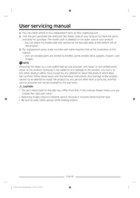
User servicing manual

  1. You can check where to buy replacement parts at http://samsung.com
  2. Visit the part purchase site and enter the model code of your product to check the parts available for purchase. The model code is labelled on the outer side of your product.
  3. You can check the model code and version on the barcode label at the bottom left of the product.
  4. For replacement parts, make sure the part name matches that of the illustration in this manual.
  5. User-serviceable parts are limited to handles (some models only), gaskets, drawers, and hinges.

NOTE

Following the repair by a non-authorised service provider, self-repair or non-professional repair of the product, Samsung is not liable for any damage to the product, any injury or any other product safety issue caused by any attempt to repair the product which does not carefully follow these repair and maintenance instructions. Any damage to the product caused by an attempt to repair the product by any person other than a Samsung certified service provider will not be covered by the warranty.

CAUTION

  • The part name listed on the site may differ from that in this manual. Please make sure you choose the right part name.
  • Replacing hinges requires extreme caution because it involves detaching the door.
  • Be sure to wear safety gloves while making repairs.

English

The actual image and provided parts of the refrigerator may differ, depending on the model and the country.

01 02 03 04 05 03 04 06 07

01 Top hinge 02 Gasket 03 Drawer 04 Handles (Applicable models only) 05 Middle hinge 06 Barcode label 07 Bottom hinge

English

Handle replacement

Model name looks like this: RB38**6****, RB38**2****, RL38**6****, RB3L**2****, RB36**6****, RB36**2****, RL36**6****, RL36**2****, RB34**6****, RB34**2****, RL34**6****, RL34**2****

What replaces the asterisks may differ depending on the model.

Asterisk(s) in the model code indicate a variant model and may replace (0-9) or (A-Z) in the model code.

SAMSUNG RL34T662ESA - Handle replacement - 1

CAUTION

  • When replacing the door handle, take care not to scratch the front of the door.
  • Firmly press the handles at the supports. Make sure there is no gap between the supports and the door.
  • Tightly fasten the screws when attaching the handle.
  • Check that the handle is firmly attached before using the product.

Tools required (not provided)

Two identical illustrations of a screwdriver with a flat blade, shown in two different angles (no text or symbols).

Phillips screwdriver Flat-head screwdriver

To detach the handles

SAMSUNG RL34T662ESA - To detach the handles - 1

NOTE

This procedure applies to both the fridge and freezer compartment.

Diagram showing a screwdriver inserted into a door panel with a close-up of the door's lock mechanism.

Diagram of a screwdriver inserted into a mechanical bracket with a black arrow indicating direction (no text or symbols).

  1. Use a flat-head screwdriver to remove the screw covers.
  2. After detaching the handle, attach the screw covers back on the screw holes.
  3. Use a Phillips screwdriver to remove the screws and detach the handle.

SAMSUNG RL34T662ESA - NOTE - 3

NOTE

Use these screws to fasten the handle on the opposite side.

  1. Assemble the new handle in the reverse order of disassembly.

English

Gasket replacement

SAMSUNG RL34T662ESA - Gasket replacement - 1

CAUTION

Make sure you firmly attach the gasket. Otherwise, cold air from the refrigerator may leak.

To remove the gasket

Diagram of a door frame with an arrow indicating direction (no text or symbols).

Open the door and remove the gasket from the door.

To replace the gasket

Diagram of a door frame with an arrow pointing to the front panel (no text or symbols).

Attach a new gasket to the refrigerator door. Make sure there is no gap between the new gasket and the door.

Drawer replacement

SAMSUNG RL34T662ESA - Drawer replacement - 1

CAUTION

Check that the drawer is inserted properly into the rail during assembly.

To remove the drawer

Diagram of a plastic drawer with a black arrow pointing to it, no text or symbols present.

Gently lift up the front of the drawer and slide it out.

To reattach the drawers

Reattaching the drawers follows the reverse order of their respective removal steps.

English

Hinge replacement

To replace the hinges, you must remove the doors first.

SAMSUNG RL34T662ESA - Hinge replacement - 1

CAUTION

- When removing the doors, take extreme caution because the doors are heavy. - Before replacing the hinges, put a soft pad such as cardboard on the floor to prevent scratches on the door when you place the doors down. - As the hinges must be handled carefully and replaced by two or more persons, we recommend you to call for professional technical service.

- If you remove the hinge without holding the door, the door may fall and cause injury. - Ensure that the shaft is firmly tightened on the hinge. - Check that the hinge is firmly attached to the cabinet. - Make sure the wire connectors are connected properly. - Be careful not to damage the wires when fastening the top cover.

SAMSUNG RL34T662ESA - CAUTION - 1

WARNING

- Tilting/laying the refrigerator requires a minimum of 2 people. - Disconnect the power cord before reversing the doors.

Tools required (not provided)

SAMSUNG RL34T662ESA - Tools required (not provided) - 1

SAMSUNG RL34T662ESA - Tools required (not provided) - 2

SAMSUNG RL34T662ESA - Tools required (not provided) - 3

Phillips screwdriver, flat-head screwdriver, 11 mm spanner

SAMSUNG RL34T662ESA - Tools required (not provided) - 4

SAMSUNG RL34T662ESA - Tools required (not provided) - 5

SAMSUNG RL34T662ESA - Tools required (not provided) - 6

10 mm socket wrench, 8 mm socket wrench, 10 mm spanner

English

Reversing the door

SAMSUNG RL34T662ESA - Reversing the door - 1

NOTE

For models with handles, reverse the handles first. (For detailed information, see the "Handle replacement (For models with bar handles)" section.)

Diagram of a battery or switch assembly with screw holes and a labeled component (no text or symbols present).

Diagram showing a device with labeled component A and an upward arrow indicating motion or direction.

Technical diagram of an electronic device showing internal components and wiring (no text or labels).

Technical diagram of a mechanical assembly with labeled components and directional arrows (no text or symbols).

  1. With the fridge door closed, use a Phillips screwdriver to remove the screws fastening the top cover (A).
  2. Gently lift the top cover (A) and place it on top of the refrigerator.

- Be careful when you lift the top cover (A). There is a wire connected underneath it.

  1. Remove the wire and the wire connector placed on the holder underneath the top cover.

- This step may not apply to some models.

SAMSUNG RL34T662ESA - NOTE - 5

CAUTION

Do not pull the connectors too hard.

  1. Disconnect the wire connector (A).
  2. This step may not apply to some models.

Technical diagram showing mechanical assembly with labeled components and directional arrow.

Diagram of a refrigerator interior showing the door and shelf, with an arrow indicating upward movement (no text or symbols present).

A

  1. Use a socket wrench (8 mm) to remove the screws fastening the top hinge (A).

CAUTION

To prevent the fridge door from falling, make sure to hold it tight while removing the screws.

  1. Open the fridge door, and then lift the door to remove it from the middle hinge. Keep the door in a safe place.

CAUTION

The door is heavy. To prevent damage or injury, use caution while removing the door.

  1. Open the freezer door, and then use a socket wrench (8 mm) to remove the screws fastening the bottom hinge (A).

Diagram showing a door opening with labeled components A and B, including an inset view of a clip mechanism.

A

  1. With the freezer door sitting on the bottom hinge (A), slowly pull the bottom hinge (A) to remove it from the holder on the bottom of the refrigerator. Once the bottom hinge (A) is removed from the holder, remove it from the freezer door, and then pull the freezer door down to remove it from the middle hinge (B).

CAUTION

To prevent the freezer door from falling, make sure to hold the freezer door tight until it is safely removed from the middle hinge (B).

  1. Use a Phillips screwdriver and socket wrench (10 mm) to remove the screws fastening the middle hinge (A).
  2. Reassemble in the opposite order of disassembly after replacing the top, middle, and/or bottom hinge.

CAUTION

• Make sure the wire connectors are connected properly. - Be careful not to damage the wires when fastening the top cover

Repair guide

Diagram of a screwdriver inserted into a mechanical clamp or bracket, with a black arrow indicating direction (no text or symbols present)

A

Technical diagram of an electrical connector with visible wiring and components (no text or symbols)

Technical diagram of a mechanical assembly with arrows indicating direction, no text or symbols present

Diagram of a refrigerator interior showing the door, rack, and storage panel with an upward arrow indicating direction (no text or symbols present)

A

Technical diagram showing a mechanical clamp or bracket with screws and a directional arrow (no text or symbols).

Diagram showing a screwdriver inserted into a mechanical bracket with a black arrow indicating direction (no text or symbols present).

Diagram showing a device with labeled component A and an upward arrow indicating motion or force direction.

Technical diagram of an electrical connector with visible wiring and components (no text or symbols).

Technical diagram of a mechanical assembly with arrows indicating direction, no text or symbols present.

Diagram of a refrigerator interior showing the door and shelf, with an arrow indicating upward movement (no text or symbols present).

A

Technical diagram showing a mechanical clamp or bracket with screws and a directional arrow (no text or symbols).

Diagram of a screwdriver inserted into a mechanical clamp or bracket, with a black arrow indicating direction (no text or symbols).

Diagram showing a device with labeled component A and an upward arrow indicating motion or direction.

Technical diagram of an electronic device showing internal components and wiring (no text or labels).

Technical diagram of a mechanical assembly with labeled components and directional arrows (no text or symbols).

Diagram of a refrigerator interior showing the door and shelf arrangement (no text or symbols).

A

A

Diagram of a screwdriver inserted into a mechanical clamp or bracket, with a black arrow indicating direction.

Diagram showing a device with labeled component A and an upward arrow indicating motion or force direction.

Technical diagram of an electrical connector with visible wiring and components.

Technical diagram of a mechanical assembly with arrows indicating direction.

Diagram of a refrigerator interior showing the door and shelf arrangement.

A

Technical diagram showing a mechanical clamp or bracket with screws and a directional arrow (no text or symbols).

Phillips screwdriver Flat-head screwdriver

Diagram of a screwdriver inserted into a mechanical bracket with a black arrow indicating direction (no text or symbols present).

Diagram showing a device with labeled component A and an upward arrow indicating motion or force direction.

Technical diagram of an electrical connector with visible wiring and components (no text or symbols).

Technical diagram of a mechanical assembly with arrows indicating direction, no text or symbols present.

Diagram of a refrigerator interior showing the door and shelf, with an arrow indicating upward movement (no text or symbols present).

Diagram showing a door opening with labeled components A and B, including an inset view of a clip mechanism.

Technical diagram showing a mechanical clamp or bracket with screws and a directional arrow.

Phillips screwdriver Flat-head screwdriver

Removing the handles

SAMSUNG RL34T662ESA - Removing the handles - 1

NOTE

Diagram showing a screwdriver inserted into a mechanical bracket with a black arrow indicating direction.

Diagram showing a device with labeled component A and an upward arrow indicating motion or force direction.

Technical diagram of an electrical connector with visible wiring and components.

Technical diagram of a mechanical assembly with arrows indicating direction.

Diagram of a refrigerator interior showing the door and shelf arrangement.

A

A

Diagram of a screwdriver inserted into a mechanical clamp or bracket, with a black arrow indicating direction (no text or symbols present).

Diagram showing a device with labeled component A and an upward arrow indicating motion or assembly.

Technical diagram of an electrical enclosure with visible wiring and components (no text or labels).

Technical diagram showing mechanical assembly with arrows indicating direction (no text or symbols).

Diagram of a refrigerator interior showing the door and shelf, with an arrow indicating upward movement.

A

Technical diagram showing a mechanical clamp or bracket with screws and a directional arrow.

Mechanical assembly diagram showing a screwdriver inserted into a bracket with a black arrow indicating direction.

Diagram showing a device with labeled component A and an upward arrow indicating motion or force direction.

Technical diagram of an electrical connector with visible wiring and components.

Technical diagram of a mechanical assembly with arrows indicating direction.

Diagram of a refrigerator interior showing the door and shelf, with an arrow indicating upward movement (no text or symbols present)

A

Technical diagram showing a mechanical clamp or bracket with screws and a directional arrow (no text or symbols)

Diagram showing a screwdriver inserted into a mechanical bracket with a black arrow indicating direction (no text or symbols present)

Diagram showing a device with labeled component A and an upward arrow indicating motion or force direction

Technical diagram of an electrical connector with visible wiring and components (no text or symbols)

Technical diagram of a mechanical assembly with arrows indicating direction, no text or symbols present

Diagram of a refrigerator interior showing the door and shelf, with an arrow indicating upward movement (no text or symbols present)

A

A

Phillips screwdriver Flat-head screwdriver

Diagram of a screwdriver inserted into a mechanical clamp or bracket, with a black arrow indicating direction (no text or symbols present)

Diagram showing a device with labeled component A and an upward arrow indicating motion or force direction

Technical diagram of an electrical connector with visible wiring and components (no text or symbols)

Technical diagram of a mechanical assembly with arrows indicating direction, no text or symbols present

Diagram of a refrigerator interior showing the door and shelf, with an arrow indicating upward movement.

A

Technical diagram showing a mechanical clamp or bracket with screws and a directional arrow.

Diagram showing a screwdriver inserted into a mechanical bracket with a black arrow indicating direction.

Diagram showing a device with labeled component A and an upward arrow indicating motion or force direction.

Technical diagram of an electrical connector with visible wiring and components.

Technical diagram of a mechanical assembly with arrows indicating direction.

Diagram of a refrigerator interior showing the door and shelf, with an arrow indicating upward movement (no text or symbols present).

A

Diagram of a mechanical clamp or bracket assembly with pins and a directional arrow (no text or symbols).

Diagram of a screwdriver inserted into a mechanical clamp or bracket, with a black arrow indicating direction (no text or symbols present).

Diagram showing a device with labeled component A and an upward arrow indicating motion or force direction.

Technical diagram of an electrical connector with visible wiring and components (no text or symbols).

Technical diagram of a mechanical assembly with arrows indicating direction, no text or symbols present.

Diagram of a refrigerator interior showing the door and shelf, with an arrow indicating upward movement (no text or symbols present).

A

Diagram of a mechanical clamp or bracket assembly with pins and a directional arrow (no text or symbols).

Mechanical assembly diagram showing a screwdriver inserted into a bracket with a black arrow indicating direction (no text or symbols).

Diagram showing a device with labeled component A and an upward arrow indicating motion or force direction.

Technical diagram of an electrical connector with visible wiring and components (no text or symbols).

Technical diagram of a mechanical assembly with arrows indicating direction and labeled component A.

Diagram of a refrigerator interior showing the door and shelf arrangement.

A

Technical diagram showing a mechanical clamp or bracket with screws and a directional arrow.

Mechanical assembly diagram showing a screwdriver inserted into a bracket with a black arrow indicating direction.

Open the doors and remove the gasket from them.

Installing the gasket

Diagram of a door frame with an arrow pointing to the front panel.

Diagram showing a device with labeled component A and an upward arrow indicating motion or force direction.

Technical diagram of an electrical connector with visible wiring and components.

Technical diagram of a mechanical assembly with arrows indicating direction, no text or symbols present.

Diagram of a refrigerator interior showing the door and shelf arrangement (no text or symbols).

A

Technical diagram showing a mechanical clamp or bracket with screws and a directional arrow (no text or symbols).

Mechanical assembly diagram showing a screwdriver inserted into a bracket with a black arrow indicating direction (no text or symbols).

Diagram showing a device with labeled component A and an upward arrow indicating motion or force direction.

Technical diagram of an electrical connector with visible wiring and components.

Technical diagram of a mechanical assembly with arrows indicating direction.

Diagram of a refrigerator interior showing the door, rack, and storage panel with an upward arrow indicating direction.

A

Technical diagram showing a mechanical clamp or bracket with screws and a directional arrow.

Diagram showing a screwdriver inserted into a mechanical clamp or bracket with a black arrow indicating direction.

A

Technical diagram of a mechanical or electrical component with internal wiring and mounting brackets.

Technical diagram of a mechanical assembly with labeled components and directional arrows.

Diagram of a refrigerator interior showing the door and shelf, with an arrow indicating upward movement.

A

Technical diagram showing a mechanical clamp or bracket with pins and a directional arrow.

Mechanical assembly diagram showing a screwdriver inserted into a bracket with a black arrow indicating direction.

Diagram showing a device with labeled component A and an upward arrow indicating motion or force direction.

Technical diagram of an electrical connector with visible wiring and components.

Technical diagram of a mechanical assembly with arrows indicating direction.

Diagram of a refrigerator interior showing the door and shelf arrangement.

A

A

01 Top hinge 02 Gasket 03 Drawer 04 Handles (only certain models) 05 Middle hinge 06 Barcode label 07 Bottom hinge

Serbian

Handle replacement

The model name looks like this: RB38**6****, RB38**2****, RL38**6****, RB3L**2****, RB36**6****, RB36**2****, RL36**6****, RL36**2****, RB34**6****, RB34**2****, RL34**6****, RL34**2****

The content that replaces the asterisks may vary depending on the model.

The asterisks in the model code indicate the model variant and can be replaced by digits (0-9) or letters (A-Z).

SAMSUNG RL34T662ESA - Handle replacement - 1

CAUTION

  • When replacing the handle on the door, be careful not to scratch the front of the door.
  • Press the handles firmly onto the supports. Make sure there is no gap between the supports and the door.
  • Tighten the screws firmly when installing the handle.
  • Before using the product, check that the handle is properly attached.

Required tools (not provided)

Two identical illustrations of a screwdriver with a flat blade, shown in two different angles.

Diagram showing a screwdriver inserted into a mechanical bracket with a black arrow indicating direction.

Open the door and remove the gasket from it.

To replace the gasket

Diagram of a door frame with an arrow pointing to the front panel.

Place the new gasket on the refrigerator door. Make sure there is no gap between the new gasket and the door.

Drawer replacement

SAMSUNG RL34T662ESA - Drawer replacement - 1

CAUTION

During installation, check that the drawer is properly inserted into the guides.

To remove the drawer

Diagram of a plastic drawer with an arrow pointing to it.

Gently lift the front of the drawer upward and pull it out.

To replace the drawers

Diagram showing a device with labeled component A and an upward arrow indicating motion or force direction

Technical diagram of an electrical connector with visible wiring and components (no text or symbols)

Technical diagram of a mechanical assembly with arrows indicating direction, no text or symbols present

  1. With the refrigerator doors closed, use a Phillips screwdriver to remove the screws securing the top cover (A).
  2. Carefully lift the top cover (A) and place it on the top of the refrigerator.

- Be careful when lifting the top cover (A). There are connected cables underneath.

  1. Remove the cable and cable connector from the holder located under the top cover.

- This step does not apply to all models.

SAMSUNG RL34T662ESA - To replace the drawers - 4

CAUTION

Diagram of a refrigerator interior showing the door and shelf arrangement (no text or symbols)

A

Diagram of a mechanical clamp or bracket with pins and a directional arrow indicating movement (no text or symbols present)

  1. While the freezer door rests on the lower hinge (A), slowly pull the lower hinge (A) to slide it out of the bracket on the bottom of the refrigerator. Once the lower hinge (A) is removed from the bracket, detach it from the freezer door, then pull the freezer door downward to remove it from the middle hinge (B).

! CAUTION

01 Top hinge 02 Gasket 03 Drawer 04 Handles (only on certain models) 05 Middle hinge 06 Barcode label 07 Bottom hinge

Croatian

Replacing the handles

The model name looks like this: RB38**6****, RB38**2****, RL38**6****, RB3L**2****, RB36**6****, RB36**2****, RL36**6****, RL36**2****, RB34**6****, RB34**2****, RL34**6****, RL34**2****

Diagram showing a screwdriver inserted into a mechanical bracket with a black arrow indicating direction (no text or symbols present)

  1. Use a flat-head screwdriver to remove the screw covers.
  2. After removing the handle, attach the screw covers back onto the screw holes.
  3. Use a Phillips screwdriver to remove the screws and detach the handle.

NOTE

Use the specified screws to attach the handle to the opposite side.

  1. Assemble the new handle in the reverse order of removal.

Croatian

Replacing the gasket

CAUTION

Make sure to firmly attach the gasket. Otherwise, cold air from the refrigerator could escape.

To remove the gasket

Diagram of a door frame with an arrow indicating direction (no text or symbols)

Open the door and remove the gasket from the door.

To replace the gasket

Diagram of a door frame with an arrow pointing to the front panel (no text or symbols)

Carefully lift the front part of the drawer and pull it out.

Reinstalling the drawers

Diagram showing a device with labeled component A and an upward arrow indicating motion or force direction.

Technical diagram of an electrical connector with visible wiring and components.

Technical diagram of a mechanical assembly with arrows indicating direction.

Diagram of a refrigerator interior showing the door and shelf arrangement.

A

  1. Using a ratchet wrench (8 mm), remove the screws that secure the upper hinge (A).

CAUTION

To prevent the door from falling, hold it firmly while removing the screws.

Technical diagram showing a bracket with screws and a directional arrow.

01 Upper hinge 02 Gasket 03 Drawer 04 Handles (only on models that have them) 05 Middle hinge 06 Barcode label 07 Lower hinge

Albanian

Diagram of a screwdriver inserted into a mechanical clamp or bracket, with a black arrow indicating direction.

Diagram showing a device with labeled component A and an upward arrow indicating motion or force direction.

Technical diagram of an electrical connector with visible wiring and components.

Technical diagram of a mechanical assembly with arrows indicating direction.

Diagram of a refrigerator interior showing the door and shelf arrangement.

A

Technical diagram showing a mechanical clamp or bracket with screws and a directional arrow.

Phillips screwdriver Flathead screwdriver

Diagram showing a screwdriver inserted into a mechanical bracket with a black arrow indicating direction.

A

Technical diagram of a mechanical assembly with visible wiring and components (no text or symbols).

Technical diagram showing mechanical assembly with arrows indicating direction (no text or symbols).

Diagram of a refrigerator interior showing the door and shelf arrangement (no text or symbols).

A

Technical diagram showing a mechanical clamp or bracket with pins and a directional arrow (no text or symbols).

Cross-head screwdriver Flat-head screwdriver

Diagram of a screwdriver inserted into a mechanical clamp or bracket, with a black arrow indicating direction (no text or symbols present)

Diagram showing a device with labeled component A and an upward arrow indicating motion or force direction

Technical diagram of an electrical connector with visible wiring and components (no text or symbols)

Technical diagram of a mechanical assembly with arrows indicating direction, no text or symbols present

Diagram of a refrigerator interior showing the door and shelf arrangement (no text or symbols)

A

Technical diagram showing a mechanical clamp or bracket with screws and a directional arrow (no text or symbols)

Diagram of a screwdriver inserted into a mechanical clamp or bracket, with a black arrow indicating direction.

Diagram showing a device with labeled component A and an upward arrow indicating motion or force direction.

Technical diagram of an electrical connector with visible wiring and components.

Technical diagram of a mechanical assembly with arrows indicating direction.

Diagram of a refrigerator interior showing the door, rack, and storage panel with an upward arrow indicating direction.

A

Diagram of a mechanical clamp or bracket with pins and a directional arrow indicating movement.

Diagram of a screwdriver inserted into a mechanical clamp or bracket, with a black arrow indicating direction (no text or symbols present).

Open the door and remove the gasket from the door.

To replace the gasket

Diagram of a door frame with an arrow pointing to the front panel (no text or symbols).

Diagram showing a device with labeled component A and an upward arrow indicating motion or force direction.

Technical diagram of an electrical connector with visible wiring and components (no text or symbols).

Technical diagram of a mechanical assembly with arrows indicating direction (no text or symbols present).

Diagram of a refrigerator interior showing the door and shelf arrangement (no text or symbols).

A

Diagram of a mechanical clamp or bracket with pins and a directional arrow indicating movement (no text or symbols present).

Diagram showing a screwdriver inserted into a mechanical bracket with a black arrow indicating direction (no text or symbols present)

Open the door and remove the gasket from the door.

Replacing the gasket

Diagram of a door frame with an arrow pointing to the front panel (no text or symbols)

Attach the new gasket to the refrigerator door. Make sure there are no gaps between the new gasket and the door.

Replacing the drawer

SAMSUNG RL34T662ESA - Replacing the drawer - 1

CAUTION

Carefully lift the front part of the drawer and pull it out.

Reinstalling the drawer

Diagram showing a device with labeled component A and an upward arrow indicating motion or force direction

Technical diagram of an electrical connector with visible wiring and components (no text or symbols)

Technical diagram of a mechanical assembly with arrows indicating direction, no text or symbols present

  1. Keep the refrigerator door closed, then use a Phillips screwdriver to remove the screws securing the top cover (A).
  2. Carefully lift the top cover (A) and place it on top of the refrigerator.

Diagram of a refrigerator interior showing the door and shelf arrangement (no text or symbols)

A

A

Manual assistant
Powered by Anthropic
Waiting for your message
Product information

Brand : SAMSUNG

Model : RL34T662ESA

Category : Refrigerator