
CHO-60CHA100T X - Range hood Vivax - Free user manual and instructions
Find the device manual for free CHO-60CHA100T X Vivax in PDF.


| Product Type | Chimney hood |
| Brand | Vivax |
| Model | CHO-60CHA100T X |
| Width | 60 cm |
| Installation Type | Wall-mounted |
| Extraction Rate | Up to 600 m³/h |
| Number of Speeds | 3 speeds + intensive |
| Noise Level | 50-68 dB |
| Lighting | LED lights, 2 x 1.5 W |
| Filter Type | Aluminum grease filter, washable |
| Charcoal Filter | Optional (recirculation mode) |
| Controls | Electronic push buttons |
| Power Supply | 220-240 V, 50 Hz |
| Rated Power | 150 W |
| Dimensions (HxWxD) | ~ 800-1100 x 600 x 500 mm |
| Weight | Approx. 15 kg |
| Exhaust Diameter | 150 mm |
| Energy Efficiency Class | A |
| Grease Filter Indicator | Yes |
| Cleaning | Wipe with damp cloth; grease filter dishwasher-safe |
| Safety Features | Motor thermal protection |
| Spare Parts Available | Filters, bulbs, charcoal filter |
Frequently Asked Questions - CHO-60CHA100T X Vivax
User questions about CHO-60CHA100T X Vivax
0 question about this device. Answer the ones you know or ask your own.
Ask a new question about this device
Download the instructions for your Range hood in PDF format for free! Find your manual CHO-60CHA100T X - Vivax and take your electronic device back in hand. On this page are published all the documents necessary for the use of your device. CHO-60CHA100T X by Vivax.
USER MANUAL CHO-60CHA100T X Vivax
Kitchen hood
Thank you for purchasing this hood.
These instructions for use are intended to provide all necessary guidance regarding the installation, use, and maintenance of the appliance.
To operate the appliance correctly and safely, carefully read the instructions before installation and use.
The kitchen hood is made of high-quality materials and has a modern design. It is equipped with a high-power electric motor and a centrifugal fan, has strong suction power, is quiet during operation, has a non-leak grease filter, and is easy to install.

IMPORTANT SAFETY INSTRUCTIONS

The lightning symbol inside a triangle warns the user of the presence of dangerous voltage that is not insulated within the product and that may be strong enough to pose a risk of electric shock.

The exclamation mark inside a triangle warns the user of important operating and maintenance instructions in the document enclosed in the packaging.

CAUTION

RISK OF ELECTRIC SHOCK DO NOT OPEN
Do not open the cover. The user must not perform any work inside the appliance under any circumstances. Only a qualified technician is authorized to perform repairs. In case of failure to comply with the safety instructions, the manufacturer will not be liable for damages.
SAFETY NOTES
- The appliance must not be used by persons (including children) with reduced physical, sensory, or mental capabilities, or lack of experience and knowledge, unless they are supervised or have been given instructions for safe use.
- Children must be supervised to ensure they do not play with the appliance.
- This appliance can be used by children aged 8 years and above and persons with reduced physical, sensory, or mental capabilities or lack of experience and knowledge, if they are supervised or have been given instructions on using the appliance safely and understand the hazards involved.
- Children must not play with the appliance.
- Children must not clean or maintain the appliance without supervision.
- Adequate ventilation must be ensured in the room when the hood is used simultaneously with gas or other fuel-burning appliances (this does not apply to appliances that recirculate or discharge air back into the room).
- If cleaning is not carried out in accordance with the instructions, a fire may occur!
- Do not flambé or cook with an open flame under the hood!
- CAUTION: Accessible parts may become very hot when used with cooking appliances.
- The exhaust air from the hood must not be discharged into a flue that is used for exhausting fumes from appliances burning gas or other fuels.
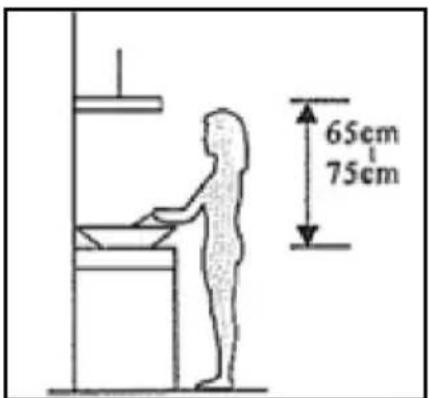
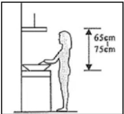
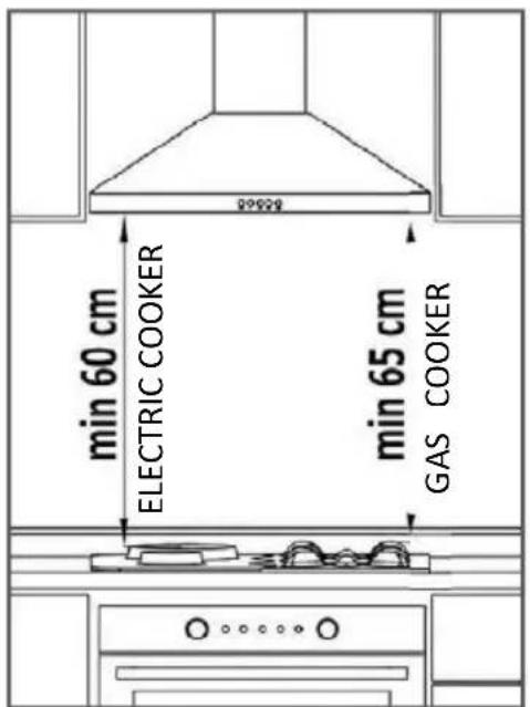
- When the hood is installed above a gas appliance, the distance must be at least 65 cm.
- Regulations concerning air discharge and room ventilation must be strictly followed.
- If the power cord is damaged, it must be replaced by the manufacturer, an authorized service center, or a similarly qualified person to avoid the risk of electric shock.
- Never disconnect the power cord from the plug by pulling the cord. Do not touch the cord with wet hands. Never move the appliance by pulling the cord, and ensure the cord does not become tangled.
- Always disconnect the appliance from the power supply before installation, disassembly, or cleaning.
- The user must not leave the appliance unattended while it is in operation.
- This appliance is intended exclusively for household use and only for the purpose for which it is intended.
- This appliance is intended only for indoor use.
- This appliance is not designed to be operated by an external timer or a separate remote control system. Your appliance must not use the same power cord or fuse as other appliances.
- Use only the appropriate power plug and socket for this appliance.
- Inadequate cleaning and maintenance of the appliance can lead to damage to the appliance or its surface, which can negatively affect the appliance's lifespan and lead to hazardous situations. Such damage is not covered by the warranty.
- WARNING: Disconnect the appliance from the power supply before changing parts or approaching moving parts.
- Do not clean the appliance with a steam cleaner.
- Use of additional accessories not approved or recommended by the appliance manufacturer may cause hazards.
- Use the appliance only for the purpose for which it is intended.


Caution! Pay attention to the warning in the operating instructions when air is being exhausted from the room.
When the hood and appliances supplied with energy other than electricity are operating simultaneously, the negative pressure in the room must not exceed 4 Pa (4×10 5 bar).

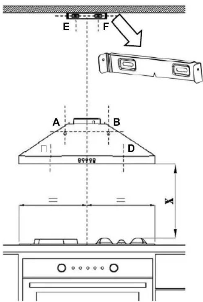
1) Drill holes of ∅8 mm in the wall at the positions marked (A,B,C,D) using the paper mounting template. Insert plastic wall plugs of ∅8 mm into the holes. (Figure 4)
(Figure 5)
2) In accordance with the required position and ceiling height at the installation site of the hood, drill ∅6 mm holes in the wall (positions E, F, Figure 4) for fixing the sheet metal bracket for the duct cover to the wall. Insert plastic wall plugs ∅6 mm into the holes. (Figure 5)
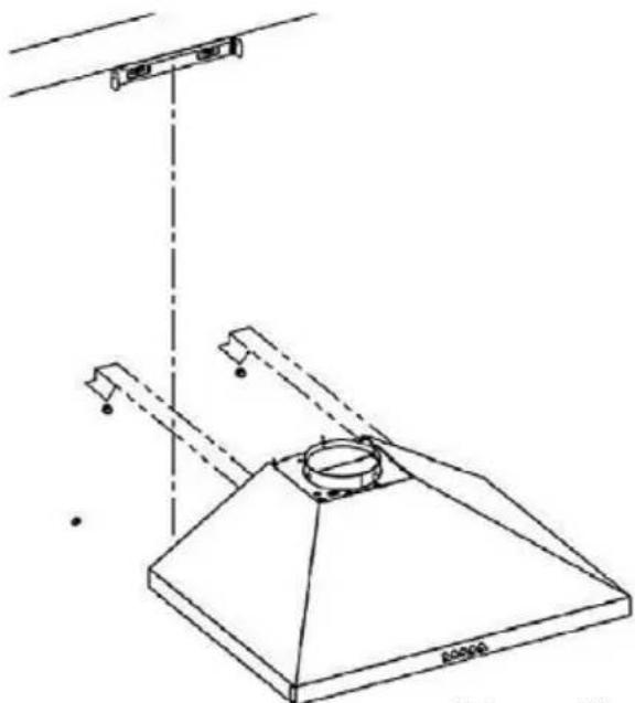
3) Tighten 2 screws 4.8x50 YSB into the wall plugs at positions A and B. Be sure to leave a gap of 5 mm between the screw head and the wall so that the hood can be hung on these screws. (Figure 5)
4) Place the sheet metal bracket for fixing the duct cover at positions E and F. Screw 3.9x22 RYSB screws into the ∅6 mm wall plugs and secure the sheet metal bracket. (Figure 5)

(Figure 6)
5) Remove the aluminum filter by pressing the filter handle and detaching the filter from the hood. (Figure 6).

(Figure 7)
6) Position the hood by hanging it on the screws through the hanging holes (positions A and B). The screws must have a gap of 5 mm between the screw head and the wall for easier "hanging". Secure the hood by tightening the 4.8x50 YSB screws from the inside of the hood into the plastic wall plugs in holes C and D. (Figure 7)
(Figure 9)

(Figure 10)
(Figure 11)
(Figure 12)
9) Carefully place the fixed air duct cover on the hood, making sure that the grooves on the hood fit with the inside of the cover.
10) Pull the inner adjustable cover upwards until it "sits" on the previously fixed sheet metal bracket (positions E and F).
(Figure 12)

(Figure 13)
11) Attach the top cover with 3.5x6.5 RYSB screws on both sides.
(Figure 13)

CORRECT

NOT RECOMMENDED

To obtain a new charcoal filter (model CHO-CP100T), contact your dealer or service center.
Replacing the light
WARNING
(Figure 14)
(Figure 15)
TROUBLESHOOTING
Be sure to read this manual before using the appliance and we strongly recommend that you keep it for future reference.
WELCOME!

Caution! Pay attention to the warning in the manual about the operation of the appliance when air is exhausted from the room.
When the extractor is installed next to a hob that is supplied with energy other than electricity (gas hob) and when the appliances operate simultaneously, the negative pressure in the room must not exceed 4 Pa (4 × 10⁵ bar).

Installation Package contents


(Figure 3)
- Height-adjustable air outlet hose cover
- Fixed air hose cover
- Housing
- Control panel
- LED lighting
- Aluminum filter
- Range hood
- Metal hose cover holder with screw set
- Instructions for use and installation, data sheet
- Paper mounting template
Placement of the range hood:
1) Drill ∅8 mm holes in the wall at the marked positions (A,B,C,D) using the paper mounting template. Insert plastic wall plugs ∅8 mm into the holes. (Figure 4)

(Figure 5)
2) According to the required position and height of the ceiling at the installation site of the hood, drill holes of ∅6 mm on the wall (positions E, F, Figure 4) for fixing the sheet metal bracket of the hose cover. Insert plastic dowels of ∅6 mm into the holes. (Figure 5)
3) Tighten 2 4.8x50 YSB screws into the dowels at positions A and B. Be sure to leave a gap of 5 mm between the screw head and the wall so that the hood can be mounted on these screws. (Figure 5)
4) Place the sheet metal holder of the hose cover so that you fix the sheet metal holder at positions E and F. Screw the 3.9x22 RYSB screws into the dowels of ∅6 mm and fix the holder. (Figure 5)

(Figure 6)
5) Remove the aluminum filter by pressing the filter handle and separating the filter from the hood. (Figure 6).

(Figure 7)
6) Install the hood by hanging it on the screws through the hanging holes (positions A and B). The screws must have a gap of 5 mm between the screw head and the wall for easier "hanging". Fix the hood by tightening the 4.8x50 YSB screws from the inside of the hood (Figure 7)
Connection to the external air outlet:
If your hood operates with internal circulation, ignore this step.
7) If your wall connection or the diameter of the aluminum pipe is 120 mm, install the 150/120 mm adapter on the hood, as shown in Figure 8.

(Figure 9)

(Figure 10)
8) Connect the flexible aluminum pipe to the air outlet of the hood. Insert the flexible aluminum pipe into the appropriate chimney connection and fix it with a clamp without over-tightening. Insert the other end of the pipe into the chimney opening in the wall. (Figures 8-9)

Before connecting the hood to the flexible hose, check the plastic flaps on the air outlet of the hood. Before connecting the pipe, start the hood and make sure that the valves move slightly upwards and allow the air to exit. Otherwise, check the flaps and their installation. (Figure 11)

(Figure 11)
Over-tightening the hose clamps may prevent the flaps from working correctly. Before connecting the duct to the flue connection, check that the hood and flaps are working correctly.

(Figure 12)
9) Carefully place the fixed air hose cover on the hood, making sure that the slots on the housing match the inside of the hood's hose cover.
10) Pull the inner adjustable cover upward until it "clicks" onto the previously attached sheet metal bracket (positions E and F). (Figure 12)

(Figure 13)
11) Attach the top cover with 3.5x6.5 RYSB screws on both sides.
(Figure 13)

CORRECT

NOT RECOMMENDED
Version 1
Periodic replacement of the activated carbon filter (model CHO-CP100T)
This applies only to the unit that is set for internal air recirculation (no external air exhaust).

To obtain a new carbon filter (model CHO-CP100T), contact your dealer or service center.
Replacing the light (Slim model)
WARNING
If the LED lighting is defective, it must be replaced by the manufacturer, its authorized service center, or a similarly qualified person to avoid the risk of electric shock.
ILCOS D code: DBR-1-H (according to IEC 61231 standard)
- LED module – translucent plastic
- Power of each luminaire: 1W
- Max power of replacement luminaires: 2 x 1W
- Luminaire power supply: 220 - 240V
- Size: diameter: 35.8 mm / height: 30 mm
If necessary, you can obtain new LED lamps from an authorized service center.
Before replacing the LED lighting, always disconnect the power cord. Remove the aluminum filter. Then:

(Figure 14)

(Figure 15)
1. Disconnect the female and male connectors of the lamp by pushing the plastic part of the tabs as shown in the figure on the left to release the locking mechanism (Figure 14).
- Hold the lamp by its body and rotate the 2 mounting tabs on the lamp clockwise or counterclockwise to align them with the slots on the housing. After aligning the mounting tabs with the slots, hold the lamp close to the body and detach the lamp from the housing (Figure 15).
TROUBLESHOOTING
(Fig. 5)
(Fig. 6)
(Fig. 7)
(Fig. 9)

(Fig. 10)
(Fig. 11)
(Fig. 12)
(Fig. 13)
CORRECT

NOT RECOMMENDED
For efficient use of the hood:
Version 1

(Fig. 14)

(Fig. 15)
PAKOM KOMPANI member of M SAN Grupa
Pakom Kompani dooel Skopje, Jadranska Magistrala no. 12, P.
EN IEC 61591:2020+A11:2020
EN 50564:2011
EN 60704-2-13:2017
member of M SAN Grupa
KOMPANI

Margareta Gnjatovic Spirov
Signed
Model: CHO-60CHA100T X
member of M SAN Grupa
Pakom Kompani dooel Skopje, Jadranska Magistrala no. 12,
P.O. Box 829, 1000 Skopje, R. of North Macedonia
VAT: MK4030992148501, NLB Bank AD 210-0453086101-55
Phn.: +389 (0)2 3202 800 Fax: +389 (0)2 3202 892
http://www.pakom.com.mk E-mail: finance@pakom.com.mk
Declaration of Conformity
EN IEC 61591:2020+A11:2020
EN 50564:2011
EN 60704-2-13:2017
Skopje, 8.4.2025
Manager
Margareta Gnjatovic Spirov
PAKOM KOMPANI member of M SAN Grupa
Signed


(Figure 3)
(Figure 6)
(Figure 7)
(Figure 8)
(Figure 9)

(Figure 10)
(Figure 11)
(Figure 12)
(Figure 13)
CORRECT
INCORRECT
Efficient use of the extractor hood:
O Off button

(Figure 14)

(Figure 15)
1) Drill holes of ∅8 mm in the wall at the marked positions (A, B, C, D) using the paper mounting template. Insert plastic wall plugs of ∅8 mm into the holes. (Figure 4)

(Figure 5)
(Figure 6)
5) Remove the aluminum filter by pressing the filter lever and removing the filter from the hood. (Figure 6).

(Figure 7)
- Position the hood so that it hangs on the screws through the hanging holes (positions A and B). The screws must have a distance of 5 mm between the screw head and the wall for easier "hanging". Secure the cover by tightening the 4.8x50 YSB screws on the inside of the hood into the plastic wall plugs in holes C and D. (Figure 7)
Connection from the external
air outlet:
(Figure 8)
(Figure 9)

(Figure 10)
(Figure 11)
(Figure 12)
9) Carefully install the fixed air duct cover onto the cover, making sure that the slots on the cover fit the inside of the cover.
10) Pull the inner adjustable cover upward until it "sits" on the previously attached sheet metal bracket (position E and F).
(Figure 12)

(Figure 13)
11) Secure the top cover with screws 3.5x6.5 RYSB on both sides
(Figure 13)

CORRECT

NOT RECOMMENDED
Version 1
O Off button
Periodic replacement of the activated carbon filter (model CHO-CP100T)

To purchase a new carbon filter (model CHO-CP100T), contact your dealer or service center.
Replacing the light bulb
WARNING
(Figure 14)

(Figure 15)
Thank you for choosing this cooker hood.
This instruction manual is designed to provide you with all required instructions related to the installation, use and maintenance of the appliance.
In order to operate the unit correctly and safely, please read this instruction manual carefully before installation and usage.
The cooker hood uses high quality materials and is made with a streamlined design. Equipped with a large power electric motor and centrifugal fan, it also provides strong suction power, low noise operation, non-stick grease filter and easy assembly installation.

It is important that you read these instructions before using your product and we strongly recommend that you keep them in a safe place for future reference.
WELCOME!
This device meets the highest standards, innovative technology and high comfort use.
Read these instructions carefully before using your new unit, and keep it carefully.
If you follow the instructions, your new appliance will provide you with many years of good service.
READ THIS MANUAL CAREFULLY AND KEEP IT FOR FUTURE REFERENCE!
IF YOU SELL OR TRANSFER THE DEVICE TO OTHER PEOPLE, BE SURE TO INCLUDE THESE INSTRUCTIONS!
IMPORTANT SAFETY INSTRUCTIONS WARNING

The flash with the symbol of an arrowhead inside an equilateral triangle alerts the user to the presence of dangerous uninsulated voltage inside the product that may be of sufficient magnitude to constitute a risk of electric shock.

The exclamation point inside an equilateral triangle alerts the user to the presence of important operating and maintenance instructions in the documentation enclosed with the package.

CAUTION

RISK OF ELECTRIC SHOCK DO NOT OPEN
Do not open the cover. Under no circumstances is the user allowed to operate inside the unit. Only a qualified technician from the manufacturer is entitled to do so. By ignoring the safety instructions, the manufacturer cannot be held responsible for any damage.
SAFETY PRECAUTIONS
- The appliance is not intended for use by persons (including children) with reduced physical, sensory, or mental capabilities, or lack of experience and knowledge, unless they have been given supervision or instruction.
- Children should be supervised to ensure that they do not play with the appliance.
- This appliance can be used by children aged 8 years and above and persons with reduced physical, sensory, or mental capabilities, or lack of experience and knowledge, if they have been given supervision or instruction concerning use of the appliance in a safe way and understand the hazards involved.
- Children shall not play with the appliance.
- Cleaning and user maintenance shall not be made by children without supervision.
- There shall be adequate ventilation in the room when the range hood is used at the same time as appliances burning gas or other fuels (not applicable to appliances that only discharge air back to the room).
- There is a fire risk if cleaning is not carried out in accordance with the instructions!
- Do not flame under the range hood.
- CAUTION: Accessible parts may become hot when used with cooking appliances.
- The air must not be discharged into a flue that is used for exhausting fumes from appliances burning gas or other fuels.
- When the range hood is located above a gas appliance, this distance shall be at least 65 cm.
- Regulations concerning the discharge of air have to be fulfilled.
- If the supply cord is damaged, it must be replaced by the manufacturer, its service agent or similarly qualified persons in order to avoid a hazard.
- Never unplug the feed cable from the plug by tugging on the cable. Do not touch the feed cable with wet hands. Never move the appliance by pulling the cord and make sure the cord cannot become entangled.
- Always disconnect the appliance from the supply before assembling, disassembling or cleaning.
- The user must not leave the device unattended while it is in work.
- This appliance is only to be used for household purposes and only for the purpose it is made for.
- This appliance is intended for indoor use only.
- The appliance is not intended to be operated by means of an external timer or a separate remote-control system. Your device must not be used connected to the same
power cable or fuse with another device.
- Only use the appropriate power connection and power socket for this device.
- Failure to maintain the appliance in a clean condition could lead to damage of the surface that could adversely affect the life of the appliance and possibly result in a hazardous situation. Such damages are not included in the warranty.
- WARNING: Switch off the appliance before changing accessories or approaching parts which move in use.
- Steam cleaner is not to be used.
- The use of accessory attachments, not recommended or sold by the appliance manufacturer, may cause hazards.
- Do not use appliance other than for its intended use.
Electrical connection
Make sure that the voltage (see name plate) and your home power supply match.
The mains plug should only be inserted into a correctly installed 220-240 V ~ 50 Hz grounded socket.
Use “Maximum 6A” fuse in the power installation to which the hood is connected both for your own safety and product safety.
No user-serviceable parts inside. Refer servicing to qualified service personnel.
Only plug this unit into a properly earthed outlet. If in doubt seek advice from a suitably qualified engineer.
Failure to follow these instructions can result in death, fire, or electrical shock.
Packing materials
Keep the packaging materials in places out of reach of the children. Access to the packaging materials by the children may lead to dangerous consequences. Do not allow the children to play with the packaging materials.
INSTALLATION
1. Prepare for installation
a. If you have an outlet to the outside, your cooker hood can be connected as below picture by means of an extraction duct (enamel, aluminum, flexible pipe or inflammable material with an interior diameter of 150mm).
b. Before installation, turn the unit off and unplug it from the outlet.
c. The cooker hood should be placed at a distance of 65~75cm above the cooking plane for best effect.


Attention! Observe the warning in the instruction sheet concerning the operation of the appliance when air is discharged from the room.
When the range hood and appliance supplied with energy other than electricity are simultaneously in operation, the negative pressure in the room must be not exceed 4 Pa (4 × 10^5 Bar)

Installation
Package included
(Figure 3)
- Height-adjustable interior flue
- Fixed exterior flue
- Cabinet
- Control panel
- LED Lighting
- Alu Filter
- Hood
- Interior flue connection bracket with screws
- User manual and Installation, Product fiche
- Assembly Template
Position of the Product:
When installation of the product is completed, there should be a clearance of 60cm between the product and electric ranges and 65 cm between the product and ranges using gas or other fuels. (Figure 3)
WARNING!
Hood should not be connected to air channel where there are other smokes.

1) Drill a hole Ø8 mm (A,B,C,D positions) on the Wall by using the installation template located in the product accessories together with the installation equipment and insert plastic wall plugs into these holes Ø8 mm. (Figure 4)

(Figure 5)
(2) Taking into consideration the height of the hood installation site, drill holes of ∅6 mm on the wall (positions E, F) for the interior flue connection sheet and insert plastic wall plugs of ∅6 mm into these holes. (Figure 5)
3) Tighten 2 of the 4.8x50 YSB screws into the wall plugs at points A and B. Make sure there is a clearance of 5 mm between the screw head and the wall. (Figure 5)
4) Fix the interior flue connection sheet into the wall plugs of ∅6 mm at points E and F using the 3.9x22 RYSB screws. (Figure 5)

(Figure 6)
5) Remove the aluminum filter unit by pressing on the spring latch at the end. (Figure 6).
(Figure 7)
6) Hang the hood by engaging it with the screws through the suspension holes at A and B, where there is a 5-mm clearance between the screw heads and the wall. Fix the product by tightening the other 4.8x50 YSB screws into the plastic wall plugs in holes C and D, visible from the inner part of the product.
(Figure 7)
Connection to external air outlet:
If your hood works with internal circulation, ignore steps 7-8.
To install carbon filters for indoor circulation, please refer to the chapter: "MAINTENANCE - Annual Change for Activated Carbon Filter"

7) If the chimney outlet diameter of your product is 150 mm and the diameter of the aluminum pipe you will use is 120 mm, attach the chimney connection adapter to the chimney outlet before installing the aluminum pipe. (Figure 8)

(Figure 9)

(Figure 10)
8) Connect the hood with the aluminum pipe. Pass the flexible aluminum pipe into the plastic flue and fix it by using the plastic cable holder or clamp without overtightening. Insert the other end of the pipe into the flue hole on the wall. (Figures 9-10)

Prior to connecting the hood with the pipe, you should control the plastic flaps at the product air exit point. Before making the pipe connection, operate the hood and make sure the flaps move upwards correctly and allow air exit. Otherwise, change the direction of the flaps. (Figure 11)

(Figure 11)
Overtightening of the cable holder or clamp when making the pipe connection may prevent operation of the flaps. Prior to connecting the pipe with the chimney of your house, you, therefore, control whether the hood operates properly by operating it.

(Figure 12)
9) Insert the interior flue into the exterior flue carefully.
10) Pull the interior flue upwards through the exterior flue and fix it with the screw 3.5×6 on the interior flue connection sheet, which you had screwed on the wall previously.
(Figure 12)
5 RYSB

(Figure 13)
11) Fix the exterior flue on the flue mounting lugs located on the upper surface of the hood (2 pieces, right-left) by using the screws 3.5x6.5 RYSB.
(Figure 13)

CORRECT

INCORRECT
To use the hood efficiently:
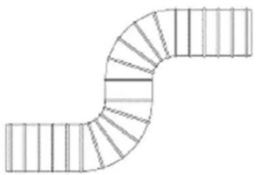
When connecting the hood to the flue, use a pipe with a diameter of 120 mm and as few bends as possible. Since bends and elbows in the aluminum pipe reduce air suction power, you should avoid using many bends and elbows as much as possible.
Pay attention to regular use of the aluminum cartridge filters and replacement times of the carbon filters (if you use your hood in recirculation mode).
WARNINGS:
Prior to operating the hood, make sure all mechanical and electrical connections are completed!
Do not leave any material inside the hood. Make sure there is no packaging material around it. Remove the blue protective band at the edges of the washable aluminum cartridge filter. Please note that if this protective band is not removed, it poses a burning risk as it is not of inflammable character.
OPERATION
Mechanical Button Control
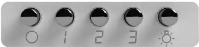
O Off button
It is used for turning off the fan.
1 Low Speed button
It is used for ventilation in the kitchen. It is suitable for simmering and cooking that do not produce much steam.
2 Medium Speed button
Airflow speed is ideal for ventilation in standard cooking operations.
3 High Speed button
When high density of smoke or steam is produced, press the high-speed button for the most effective ventilation.

Light button
NOTE: If Low / Medium / High speed buttons are pressed at the same time, the unit will only operate at the highest speed.
MAINTENANCE
Before any maintenance or cleaning, switch the unit off and disconnect it from the mains supply!
Regular Cleaning
Use a soft cloth moistened with hand-warm mildly soapy water or household cleaning detergent. Never use metal pads, chemical, abrasive material or stiff brush to clean the unit.
Grease Filter Monthly Cleaning
WARNING: Clean the filter every month to prevent any risk of fire.
The filter collects grease, smoke and dust.
The filter is directly connected with the efficiency of the cooker hood. If not cleaned, the grease residue (potentially flammable) will saturate on the filter. Clean it with household cleaning detergent.
Aluminum cartridge filters are washable in the dishwashing machines.
Aluminum cartridge filter should be washed once every several months (after each 40 operating hours on average) depending on frequency of use, with hot soapy water or, if possible, individually in the dishwashing machine (maximum 60°C).
After washing, aluminum cartridge filter and its frame may discolour. This is normal and does not affect the function of the filters.
Remove the aluminum cartridge filter by pushing the spring catch at the end.
After cleaning, allow it to dry. Do not put it in place before it gets dry.

Annual Change for Activated Carbon Filter (model: CHO-CP100T)
Applies to units with internal air circulation (not vented to the outside).
This filter traps odors and must be replaced at least once a year, depending on how frequently the cooker hood is used.

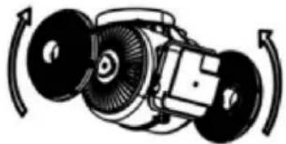
To purchase a new Carbon Filter (CHO-CP100T), contact your dealer or service center.
Light Bulb Replacement
WARNING
If the supply LED bulb is damaged, it must be replaced by the manufacturer, its service agent, or similarly qualified persons to avoid a hazard.
The hood is equipped with a LED-based lighting system.
Compared to ideal lighting and normal lamps, LEDs provide a service life 10 times longer, with energy savings up to 90%.
If you encounter any physical deformation of the lamp or any problem with the lighting, please contact the authorized service center.
Technical specifications:
ILCOS D code: DBR-1-H (ILCOS D code as per standard IEC 61231) - LED module – semi-transparent plastic - Rated power of each lamp: 1W - Maximum lamp potential power for replacement: 2 x 1W - Voltage range of the lamp: 220 - 240V - Product sizes: diameter: 35.8 mm / height: 30 mm
If required, you may acquire new lamps from the authorized service center.
Prior to replacement of the lamps, remove the power cable of the hood. Then lift the front glass upward and remove the aluminum cartridge filter. Afterwards:

(Figure 14)

(Figure 15)
- Disconnect the female and male connectors of the lamps by pushing back part of the plastic lug as shown in the figure at left here to release the locking mechanism (Figure 14).
- Hold the lamp at its body and rotate 2 retaining lugs on the lamp clockwise or anticlockwise to match with the gaps on the lighting panel. After bringing the retaining lugs to align with the gaps, hold the lamp at its body and bring it out (Figure 15)
TROUBLESHOOTING
The following simple issues can be handled by the user. Please call the after-sale service department if the issues are not settled!
| Problem Possible cause | Solution | |
| Light on, but fan does not work | The fan blade is jammed | Switch of the unit and repair by The motor is damaged. qualified service personnel only |
| The motor is damaged | ||
| Both light and fan do not work | The light bulb burned | Replace the bulb with correct rating |
| Power cord looses | Plug in to the power supply again. | |
| Serious Vibration of the unit | The fan blade is damaged. | Switch of the unit and repair by qualified service personnel only. |
| The fan motor is not fixed tightly. | Switch of the unit and repair by qualified service personnel only | |
| The unit is not hung properly on the bracket | Take down the unit and check whether the bracket is in proper location. | |
| Suction performance not good | Too long distance between the unit and the cooking plane | Readjust the distance to 65-75cm |
TRANSPORT AND SERVICE
WARNING: Handling and transportation. It is required to perform transportation of device in its own original box. Metal, Plastic or Glass parts may be broken during packaging. Its electrical parts may be damaged.
Unplug it while it is operating for transport, maintenance or repair purposes.
TECHNICAL SPECIFICATIONS
| Voltage / Total power 220-240V, 50Hz / Max 102W | |
| Motor Power 100W | |
| Lamp Power 2x 1W | |
| Control Panel Mechanic, 3 Speed | |
| Air Outlet connection diameter | ∅150mm |
| Dimensions (WxDxH) mm 596 | x 453 x 695-880mm |
| Power consumption in Off mode | 0W |
| Power consumption in Standby mode | N/A |
DISPOSAL OF ELECTRICAL AND ELECTRONIC EQUIPMENT
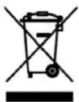
To protect our environment and to recycle the raw materials used as completely as possible, the consumer is asked to return unserviceable equipment to the public collection system for electrical and electronic waste. The symbol of the crossed-out wheeled bin indicates that this product must be returned to the collection point for electronic waste to feed it by recycling the best possible raw material recycling.
By ensuring this product you will prevent possible negative effects on the environment and human health, which could otherwise be caused due to improper disposal of that product. The recycling of materials from this product will help to preserve a healthy environment and natural resources.
For detailed information about the collection of EE products contact the dealer where you purchased the product.
EU DECLARATION OF CONFORMITY
This device is manufactured in accordance with the applicable European standards and in accordance with all applicable Directives and Regulations.
EU declaration of conformity can be downloaded from the following link: www.msan.hr/dokumentacijaartikala

WARRANTY CERTIFICATE HR
VIVAX
DEVICE MODEL
SERIAL NUMBER
DATE OF SALE
SELLER'S INVOICE NUMBER
SELLER'S SIGNATURE AND STAMP
SELLER'S SIGNATURE AND STAMP
WARRANTY STATEMENT
- With this warranty, the manufacturer of the product, through KIM TEC d.o.o., as the importer and warranty provider in Bosnia and Herzegovina, guarantees free repair of the product in accordance with applicable regulations and the conditions described in this warranty certificate. With this warranty, we guarantee that the subject of this warranty will operate without defects caused by possible poor workmanship and poor materials. Any defects that may occur will be repaired free of charge at an authorized service center within the warranty period.
- WARRANTY CONDITIONS: The warranty period begins on the date of purchase of the product and lasts:
| 60 MJESECI (5 godina) | HLADNJACI,VERTIKALNE I HORIZONTALNE ŠKRINJE |
| 36 MJESECI (3 godine) | ŠTEDNJACI, PERILICE I SUŠILICE RUBLJA, PERILICESUĐA, KUHINJSKE NAPE, UGRADBENE PEĆNICE IPLOČE, GRIJALICE VODE |
- In the event of a defect in the product covered by this warranty, we undertake to repair it as soon as possible, and no later than within 30 days. If the product cannot be repaired or is not repaired within 30 days, it will be replaced with a new one.
- The warranty is recognized only with the purchase receipt and this warranty card, which must be properly filled out, i.e., it must contain the date of sale, the seller's stamp and signature.
- The warranty provider ensures service and spare parts for 7 years from the date of purchase.
THE WARRANTY DOES NOT COVER:


- KITCHEN HOOD
- THANK YOU FOR PURCHASING THIS HOOD
- IMPORTANT SAFETY INSTRUCTIONS
- CAUTION
- RISK OF ELECTRIC SHOCK DO NOT OPEN
- SAFETY NOTES
- REPLACING THE LIGHT
- WARNING
- TROUBLESHOOTING
- WELCOME
- PLACEMENT OF THE RANGE HOOD
- CONNECTION TO THE EXTERNAL AIR OUTLET
- VERSION
- PERIODIC REPLACEMENT OF THE ACTIVATED CARBON FILTER (MODEL CHO-CP100T)
- REPLACING THE LIGHT (SLIM MODEL)
- IF THE LED LIGHTING IS DEFECTIVE, IT MUST BE REPLACED BY THE MANUFACTURER, ITS AUTHORIZED SERVICE CENTER, OR A SIMILARLY QUALIFIED PERSON TO AVOID THE RISK OF ELECTRIC SHOCK
- FOR EFFICIENT USE OF THE HOOD
- DECLARATION OF CONFORMITY
- EFFICIENT USE OF THE EXTRACTOR HOOD
- O OFF BUTTON
- CONNECTION FROM THE EXTERNAL
- REPLACING THE LIGHT BULB
- READ THESE INSTRUCTIONS CAREFULLY BEFORE USING YOUR NEW UNIT, AND KEEP IT CAREFULLY
- READ THIS MANUAL CAREFULLY AND KEEP IT FOR FUTURE REFERENCE
- IF YOU SELL OR TRANSFER THE DEVICE TO OTHER PEOPLE, BE SURE TO INCLUDE THESE INSTRUCTIONS
- IMPORTANT SAFETY INSTRUCTIONS WARNING
- SAFETY PRECAUTIONS
- ELECTRICAL CONNECTION
- PACKING MATERIALS
- INSTALLATION
- PREPARE FOR INSTALLATION
- POSITION OF THE PRODUCT
- CONNECTION TO EXTERNAL AIR OUTLET
- TO USE THE HOOD EFFICIENTLY
- WARNINGS
- OPERATION
- MECHANICAL BUTTON CONTROL
- LOW SPEED BUTTON
- MEDIUM SPEED BUTTON
- HIGH SPEED BUTTON
- LIGHT BUTTON
- MAINTENANCE
- REGULAR CLEANING
- GREASE FILTER MONTHLY CLEANING
- ANNUAL CHANGE FOR ACTIVATED CARBON FILTER (MODEL: CHO-CP100T)
- LIGHT BULB REPLACEMENT
- TRANSPORT AND SERVICE
- TECHNICAL SPECIFICATIONS
- DISPOSAL OF ELECTRICAL AND ELECTRONIC EQUIPMENT
- EU DECLARATION OF CONFORMITY
- WARRANTY CERTIFICATE HR
- VIVAX
- DEVICE MODEL
- SERIAL NUMBER
- DATE OF SALE
- SELLER'S INVOICE NUMBER
- SELLER'S SIGNATURE AND STAMP
- WARRANTY STATEMENT
- THE WARRANTY DOES NOT COVER
Brand : Vivax
Model : CHO-60CHA100T X
Category : Range hood