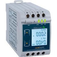
SIRAX BT5200 - Energy meter Camille Bauer - Free user manual and instructions
Find the device manual for free SIRAX BT5200 Camille Bauer in PDF.


| Product Type | Energy Meter |
| Brand | Camille Bauer |
| Model | SIRAX BT5200 |
| Measurement Types | Active energy (kWh), Reactive energy (kVARh), Apparent energy (kVAh) |
| Accuracy Class | Class 1 (IEC 62053-21) |
| Rated Current | 5 A secondary (CT operated) |
| Voltage | 3 x 230/400 V AC (L-L/L-N) |
| Frequency | 50/60 Hz |
| Display | LCD, backlit, 6+1 digits |
| Communication | RS485 Modbus RTU, pulse output |
| Dimensions (H x W x D) | 96 x 96 x 65 mm (panel cutout 92 x 92 mm) |
| Weight | Approx. 0.3 kg |
| Auxiliary Supply | 80 - 265 V AC/DC, <2 W |
| Operating Temperature | -10°C to +55°C |
| Storage Temperature | -25°C to +70°C |
| Protection Rating | IP51 (front face), IP20 (terminals) |
| Mounting | Panel mount (DIN 96 x 96) |
| Standards | IEC 62053-21, IEC 62053-22, IEC 62052-11 |
| Maintenance | Clean with dry cloth; no user-serviceable parts inside |
| Safety | Indoor use only; follow local electrical regulations |
| Spare Parts / Reparability | Contact manufacturer for service; no field-replaceable parts |
| General Information | Electronic energy meter for billing and sub-metering in commercial/industrial applications |
Frequently Asked Questions - SIRAX BT5200 Camille Bauer
User questions about SIRAX BT5200 Camille Bauer
0 question about this device. Answer the ones you know or ask your own.
Ask a new question about this device
Download the instructions for your Energy meter in PDF format for free! Find your manual SIRAX BT5200 - Camille Bauer and take your electronic device back in hand. On this page are published all the documents necessary for the use of your device. SIRAX BT5200 by Camille Bauer.
USER MANUAL SIRAX BT5200 Camille Bauer
Operating Instructions
SIRAX BT5200
Transducer for AC current


CAMILLE BAUER
Camille Bauer Metrawatt AG
Aargauerstrasse 7
CH-5610 Wohlen/Switzerland
Tel: +41 56 618 21 11
Fax: +41 56 618 21 21
info@cbmag.com
www.camillebauer.com
Legal information
Warning notices
In this document warning notices are used, which you have to observe to ensure personal safety and to prevent damage to property. Depending on the degree of danger the following symbols are used:

If the warning notice is not followed death or severe personal injury will result.

If the warning notice is not followed damage to property or severe personal injury may result.

If the warning notice is not followed the device may be damaged or may not fulfill the expected functionality.
Qualifi ed personnel
The product described in this document may be handled by personnel only, which is qualified for the respective task. Qualified personnel have the training and experience to identify risks and potential hazards when working with the product. Qualified personnel are also able to understand and follow the given safety and warning notices.
Intended use
The product described in this document may be used only for the application specified. The maximum electrical supply data and ambient conditions specified in the technical data section must be adhered. For the perfect and safe operation of the device proper transport and storage as well as professional assembly, installation, handling and maintenance are required.
Disclaimer of liability
The content of this document has been reviewed to ensure correctness. Nevertheless it may contain errors or inconsistencies and we cannot guarantee completeness and correctness. This is especially true for different language versions of this document. This document is regularly reviewed and updated. Necessary corrections will be included in subsequent version and are available via our webpage http://www.camillebauer.com.
Feedback
If you detect errors in this document or if there is necessary information missing, please inform us via e-mail to: customer-support@camillebauer.com
Table of content
1. Introduction 4
1.1 Purpose of this document 4
1.2 Scope of supply 4
1.3 Further documents 4
2. Safety notes .... 4
3. Device overview .... 5
4. Mechanical mounting .... 5
4.1 Mounting 5
4.2 Demounting of the device 5
5. Electrical connections ...... 6
5.1 General safety notes 6
5.2 Cross sections and tightening torques 6
5.3 Inputs 6
5.4 Power supply 6
5.5 Connection Diagram 7
5.6 Modbus interface RS485 7
6. Commissioning 7
6.1 Operating the device 8
6.2 LED indication 8
6.3 Input and output screens 8
7. Programming 9
7.1 Programming via Front LCD & Two keys 9
7.1.1. Password Protection 9
7.1.1.1 Password Verification.... 9
7.1.1.2 New/Change Password 10
7.1.2. Current Transformer parameter selection 11
7.1.2.1 Current Transformer primary value 11
7.1.2.2 Current Transformer secondary value 12
7.1.3. Communication Parameter Selection : 13
7.1.3.1 Address Setting 13
7.1.3.2 RS 485 Baud Rate 14
7.1.3.3 RS 485 Parity Selection: 14
7.1.4. Output Type Selection 15
7.1.4.1 Output 1 Type selection 15
7.1.4.2 Output 2 Type Selection 15
7.1.5. Input parameter selection 16
7.1.5.1 End value of Input 16
7.1.5.2 Start value of Input 17
7.1.6 Output parameter selection 19
7.1.6.1 Output 1 parameter selection 19
7.1.6.1.1 End value of output 1 19
7.1.6.1.2 Start value of output 1 20
7.1.6.1.3 Elbow value of output 1 21
7.1.6.2 Output 2 parameter selection 22
7.1.6.2.1 End value of output 2 22
7.2. Programming via the programming connection and the PRKAB5000 programming cable 26
7.3. Programming via the RS485 (Modbus) interface 26
7.4. DIP Switch Setting for Output 26
8. Service, maintenance and disposal 27
8.1 Repair work and modifications....27
8.2 Calibration and new adjustment 27
8.3 Cleaning 27
8.4 Disposal 27
8.5 Return 27
9. Technical data 28
10. Dimensional drawings....30
11. Interface Definition Modbus RTU ....30
11.1 Modbus functions ......31
11.2 Datatyp... 31
11.3 Modbus register....32
1. Introduction
1.1 Purpose of this document
This document describes the universal measurement device SIRAX BT5200. It is intended to be used by:
• Installation personnel and commissioning engineers
• Service and maintenance personnel
- Planners
Scope
This handbook is valid for all hardware versions of the BT5200. Some of the functions described in this document are available only, if the necessary optional components are included in the device.
Required knowledge
A general knowledge in the field of electrical engineering is required. For assembly and installation of the device knowledge of applicable national safety regulations and installation standard is required.
1.2 Scope of supply
• Measurement device SIRAX BT5200
• Safety instructions (multiple languages)
1.3 Further documents
The following documents are provided electronically via www.camillebauer.com:
• Safety instructions SIRAX BT5200
- Operating Instructions SIRAX BT5200
• Data sheet SIRAX BT5200
2. Safety notes

Device may only be disposed in a professional manner!

The installation and commissioning should only be carried out by trained personnel.
Check the following points before commissioning:
- that the maximum values for all the connections are not exceeded, see „Technical data“ section,
- that the connection wires are not damaged, and that they are not live during wiring,
- that the power flow direction and the phase rotation are correct.
The instrument must be taken out of service if safe operation is no longer possible (e.g. visible damage). In this case, all the connections must be switched off. The instrument must be returned to the factory or to an authorized service dealer.
It is forbidden to open the housing and to make modifications to the instrument. The instrument is not equipped with an integrated circuit breaker. During installation check that a labeled switch is installed and that it can easily be reached by the operators.
Unauthorized repair or alteration of the unit invalidates the warranty.
3. Device overview
The SIRAX BT5200 is a top-hat rail mounted Transducer and used to measure and convert AC Current input into an proportional DC current or voltage output signal. Input Current and Output Voltage/Current is displayed on LCD and indicated by LED's.
4. Mechanical mounting
The SIRAX BT5200 is designed for panel mounting.

Please ensure that the operating temperature limits are not exceeded when determining the place of mounting (place of measurement): 0 ... +45 °C
4.1 Mounting
Dimensional drawing BT5200: See section 10
Any mounting position is possible. Device may be clipped onto a top-hat rail according EN 50022.

natural_image
Diagram of a mechanical component with a curved base and a vertical wall, showing a force or motion direction indicated by an arrow (no text or symbols present)4.2 Demounting of the device
Disassembly of the device requires that all connected wires be without current. First, remove all push terminals and the wires of the current and voltage inputs. Ensure that possible current transformers are short-circuited before the current connections on the device are opened. Release the transducer from a top-hat rail.

natural_image
Diagram of a tool interacting with a mechanical component, showing a lever and base (no text or symbols)5. Electrical connections

Ensure under all circumstances that the leads are free of potential when connecting them!
5.1 General safety notes

Please observe that the data on the type plate must be adhered to!
The national provisions have to be observed in the installation and material selection of electric lines!
| Symbol Meaning | |
 | Device may only be disposed of in a professional manner! |
 | Double insulation, device of protection class 2 |
| CAT III Measurement category CAT III for current inputs and power supply | |
 | CE conformity mark. The device fulfi IIs the requirements of the applicable EC directives. See declaration of conformity. |
 | Caution! General hazard point. Read the operating instructions. |
 | Attention: Danger to life! |
| [92va] | Please note |
5.2 Cross sections and tightening torques
Terminals 1 ... 8
Single wire: ≤ 4,0mm 2 or multiwire with end splices: 2 x 2,5mm 2
Torque: 0.5 ... 0.6Nm rsp. 4.42 ... 5.31 lbf in
Terminal A, B, G
Single wire: ≤ 1,5mm2 or multiwire with end splices: 2× 0,5mm2
Torque: max. 0.5 Nm rsp. 4.42 lbf in
5.3 Inputs

No fuse may be connected upstream of the current measurement inputs!
When using current transformers their secondary connectors must be short-circuited during installation and before removing the device. Never open the secondary circuit under load.
The connection of the inputs depends on the configured system (connection type).
5.4 Power supply

A marked and easily accessible current limiting switch has to be arranged in the vicinity of the device for turning off the power supply. Fusing should be 10 Amps or less and must be rated for the available voltage and fault current.
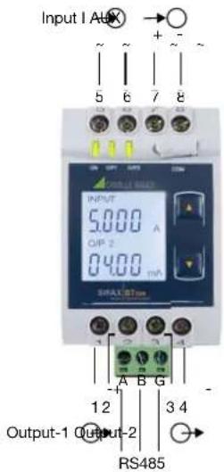
5.5 Connection Diagram
| Connection | Terminal details | |
| Measuring input | I/P ~ | 5 |
| I/P ~ | 6 | |
| Auxiliary power supply | AUX + | 7 |
| AUX - | 8 | |
| Measuring output - 1 | O/P1 + | 1 |
| O/P1 - | 2 | |
| Measuring output - 2 | O/P2 + | 3 |
| O/P2 - | 4 | |
| Modbus | A | - |
| B | - | |
| G | - | |
5.6 Modbus interface RS485
Via the optional Modbus interface measurement data may be provided for a superior system.
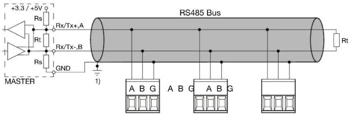
1) One ground connection only. This is possibly made within the master (PC).
Rt: Termination resistors: 120 Ω each for long cables (> approx. 10 m)
Rs: Bus supply resistors, 390 Ω each
The signal wires (A, B) have to be twisted. G can be connected via a wire or via the cable screen. In disturbed environments shielded cables must be used. To avoid the possibility of loop currents, an Earth connection should be made at one point on the bus. Supply resistors (Rs) have to be present in bus master (PC) interface. Stubs should be avoided when connecting the devices. A pure daisy chain network is ideal.
You may connect up to 32 Modbus devices to the bus. A proper operation requires that all devices connected to the bus have equal communication settings (baud rate, transmission format) and unique Modbus addresses.
The bus system is operated half duplex and may be extended to a maximum length of 1200 m without repeater.
6. Commissioning

Before commissioning you have to check if the connection data of the device match the data of the plant. If so, you can start to put the device into operation by switching on the power supply and the measurement inputs.
| SIRAX BT5200 TRMS Current Transducer | |
| ORDER CODE: 175283 SR No.: 16/02/0001 OPTION: RS485, 2 Output | CAT III, 300V |
| 7±8=→AUX: 60...300V=, 50/60Hz, 10VA | |
| 5~6~→INPUT: 0...5 A, 50/60Hz | |
| 1+2→Output 1: 4...20mA, Rint≤750Ohm | |
| 3+4→Output 2: 0...10V, Rint≥5kOhm | |
| Camilie Bauer Metrawatt AG Aargauerstrasse 7 / 5610 Wohlen / Switzerland | |
Label version
6.1 Operating the device

SIRAX BT5200 can be configured and programmed at site for the following:
CT Primary, CT Secondary (5A or 1A), Input parameters (i.e start, end and elbow value of Input) and Output parameters (i.e as Voltage or as Current and start, end and elbow value of outputs).
The front panel has two keys through which the user may scroll through the output screens and configure the product.
Operation is performed by means of 2 keys:
2 keys "UP" und "DOWN" for navigation and for the selection of values.
6.2 LED indication
| LED LED OPERATING CONDITION LED OPERATING STATUS | ||
| ON Aux. Supply healthy condition Green LED continuous ON | ||
| O/P 1 | Output 1 voltage Green LED continuous ON | |
| Output 1 current Red LED continuous ON | ||
| O/P 2 | Output 2 voltage Green LED continuous ON | |
| Output 2 current Red LED continuous ON | ||
Table 1: Measured parameters
| Measured parameters Unit of Measurement | |
| Current Amp | |
6.3 Input and output screens
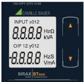
Screen 1: Display Test
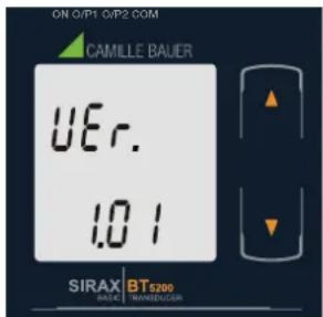
Screen 2: Version Screen
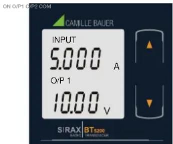
Screen 3: Current Input and Output 1 as Voltage
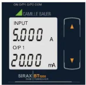
Screen 4: Current Input and Output 1 as Current
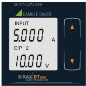
Screen 5: Current Input and Output 2 as Voltage
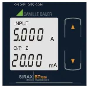
Screen 6: Current Input and Output 2 as Current
7. Programming
Programming of transducer can be done in three ways:
1) Programming via Front LCD & two keys.
2) Programming via Programming port available at front of Transducers using optional PRKAB5000 adapter
3) Programming via optional RS485 (Modbus) communication port.
7.1 Programming via Front LCD & Two keys
The following sections comprise step by step procedures for configuring the SIRAX BT5200 for individual user requirements.
To access the set-UP screens, press and hold the “DOWN” and “UP” Key simultaneously for 5 seconds. This will take the User into the Password Protection Entry Stage.
7.1.1. Password Protection
7.1.1.1 Password Verification
Password protection can be enabled to prevent unauthorised access to set-up screens, by default password protection is not enabled.
Password protection is enabled by selecting a four digit number other than 0000, setting a password of 0000 disables the password protection.

Enter Password, prompt for first digit. (*Denotes that digit will be fl ashing).
Pressing the “down” key will scroll the value of the first digit from 0 through to 9, the value will wrap from 9 round to 0.
Pressing the “Up” key will advance the operation to the next digit and set the first digit.
In the special case where the Password is "0000" pressing the "Up" key when prompted for the first digit will advance to the "Password Set/Confirmed" screen.

Enter Password, fi rst digit entered, prompt for second digit.
(*Denotes that digit will be fl ashing).
Pressing the “down” key will scroll the value of the second digit from 0 through to 9, the value will wrap from 9 round to 0.
Pressing the “▶p” key will advance the operation to the next digit and set the second digit.

Enter Password, second digit entered, prompt for third digit.
(*Denotes that digit will be flashing).
Pressing the “ Down” key will scroll the value of the third digit from 0 through to 9, the value will wrap from 9 round to 0.
Pressing the “ p” key will advance the operation to the next digit and set the third digit.
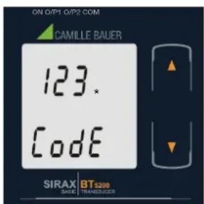
Enter Password, third digit entered, prompt for fourth digit.
(*Denotes that digit will be fl ashing).
Pressing the “ Down” key will scroll the value of the fourth digit from 0 through to 9, the value will wrap from 9 round to 0.
Pressing the “Up” key will advance the operation to the “Password Set/Confirmed” and set the fourth digit.

Password Set/Confirmed
Pressing “ Down” key will enter to the “New / change Password” entry stage.(section 7.1.1.2)
Pressing the “Up” key will advance to the Potential Transformer parameter selection(section 7.1.2).

Password Incorrect.
This screen is displayed when the unit has not accepted the Password entered.
Pressing the " Down" key will re-enter to the "Enter Password" entry stage.
Pressing the "Up" key will exit the setup menu.
7.1.1.2 New/Change Password
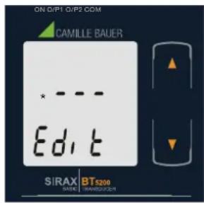
New / Change Password
(*Denotes that digit will be fl ashing).
Pressing the “down” key will scroll the value of the first digit from 0 through to 9, the value will wrap from 9 round to 0.
Pressing the “■p” key will advance the operation to the next digit and set the first digit, in this case to “4”

Enter New / Change Password, first digit entered, prompting for second digit. (*Denotes that digit will be fl ashing).
Pressing the “Down” key will scroll the value of the second digit from 0 through to 9, the value will wrap from 9 round to 0.
Pressing the “-p” key will advance the operation to the next digit and set the second digit, in this case to “1”

Enter New / Change Password, second digit entered, prompting for third digit. (*Denotes that digit will be flashing).
Pressing the “Down” key will scroll the value of the third digit from 0 through to 9, the value will wrap from 9 round to 0.
Pressing the “■p” key will advance the operation to the next digit and set the third digit, in this case to “4”

Enter New / Change Password, third digit entered, prompting for fourth digit. (* denotes that digit will be fl ashing).
Pressing the “ Down” key will scroll the value of the fourth digit from 0 through to 9, the value will wrap from 9 round to 0.
Pressing the “Up” key will advance the operation to the “New Password Confirmed” and set the fourth digit, in this case to “1”.
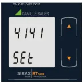
New/changed Password confirmed
Pressing the “ Down” key will re-enter to the “New/Change Password” entry stage.
Pressing the “+” key will confirm New Password and advance to the Potential Transformer parameter selection (section 7.1.2).
7.1.2. Current Transformer parameter selection
7.1.2.1 Current Transformer primary value
This screen allows the user to set the CT Primary value between 1 to 9999.
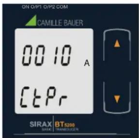
Pressing the "■own" key will enter the "New/Change CT Primary value edit" mode.
Pressing “p” key will confirm the present value as CT Primary and advance to the CT secondary selection (section 7.1.2.2).

New / Change CT Primary value
(*Denotes that decimal point will be fl ashing).
Pressing the “■own” key will scroll the value of the first digit from 0 through to 9, the value will wrap from 9 round to 0.
Pressing the “-” key will advance the operation to the next digit and set the first digit, in this case to “0”.

Enter New / Change CT Primary value, first digit entered, prompting for second digit. (*Denotes that digit will be flashing).
Pressing the “down” key will scroll the value of the second digit from 0 through to 9, the value will wrap from 9 round to 0.
Pressing the “+” key will advance the operation to the next digit and set the second digit, in this case to “0”.

Enter New / Change CT Primary value, first digit entered, prompting for second digit. (*Denotes that digit will be flashing).
Pressing the “down” key will scroll the value of the second digit from 0 through to 9, the value will wrap from 9 round to 0.
Pressing the “Up” key will advance the operation to the next digit and set the second digit, in this case to “0”.

Enter New / Change CT Primary value, second digit entered, prompting for third digit. (*Denotes that digit will be flashing).
Pressing the “Down” key will scroll the value of the third digit from 0 through to 9, the value will wrap from 9 round to 0.
Pressing the “-p” key will advance the operation to the next digit and set the third digit, in this case to “5”.

New / Change CT Primary value
Pressing the “ Down” key will re-enter to the “New / Change CT Primary value” edit mode.
Pressing the “■p” key will confirm New CT Primary value and advance to the CT secondary selection (section 7.1.2.2).
7.1.2.2 Current Transformer secondary value
This screen allows the user to set the CT Secondary value.

Pressing the “down” key will enter the “New/Change CT Secondary value edit” mode.
Pressing the “■p” key will confirm the present value as CT Secondary and advance to the Communication parameter Selection (section 7.1.3).
![ON GYPT QIP2 COM CAMILLE BAUER * A [ t - 5 ] SIRAX BT5200 BASE TRANSDUCER](/content/2026/06/1404989/images/927e12d5bf98253d580bb34a2c51b864eba8e5f61d329d9422eda30bfe483c16.jpg)
New / Change CT Secondary value
(*Denotes that digit will be fl ashing).
Pressing the “Down” key will scroll the value of the fourth digit from 1 through to 5, the value will wrap from 5 round to 1.
Pressing the “■p” key to advance the operation to the “New / Changed CT Secondary value” and sets the fourth digit, in this case to “5”.

New/changed CT Secondary value confirmed.
Pressing the “ Down” key will return to the “New / Change CT Secondary value edit” mode.
Pressing the “-” key will confirm the CT Secondary and advance to the Communication parameter Selection (section 7.1.3).
7.1.3. Communication Parameter Selection :
7.1.3.1 Address Setting
This screen applies to the RS 485 output only.
This screen allows the user to set RS485 parameter for instruments. The range of allowable address is 1 to 247.
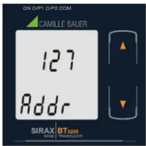
Pressing “ Down” key will advance to the “New/Change address value edit” mode.
Pressing the “-p” key will confirm the present value as Address and advance to Baud Rate selection (section 7.1.3.2).

New/changed Address value
(*Denotes that digit will be fl ashing).
Pressing the “-” key will scroll the value of the second digit from 0 through to 2, the value will wrap from 2 round to 0.
Pressing the “■”p key will advance the operation to the next digit and set the second digit, in this case to “0”.
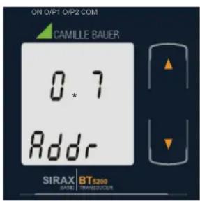
Enter New / Change Address value, second digit entered, prompting for third digit. (*Denotes that digit will be fl ashing).
Pressing the “-” key will scroll the value of the third digit from 0 through to 9, the value will wrap from 9 round to 0.
Pressing the “■p” key will advance the operation to the next digit and set the third digit, in this case to “9”.

Enter New / Change Address value, third digit entered, prompting for fourth digit. (* denotes that digit will be fl ashing).
Pressing the “ Down” key will scroll the value of the fourth digit from 0 through to 9, the value will wrap from 9 round to 0.
Pressing the “■” p key will advance the operation to the “New / Changed Address value confirmed” and set the fourth digit, in this case to “6”.

New/changed Address value confirmed.
Pressing the “ Down” key will re-enter to the “New / Change Address value edit” mode.
Pressing the “■p” key will confirm New Address value and advance to Baud Rate selection (section 7.1.3.2).
7.1.3.2 RS 485 Baud Rate

This screen allows the user to set Baud Rate of RS 485 port. The values displayed on screen are in kbaud.
Pressing the “Down” key will enter the “Baud Rate edit” mode and scroll the value through 2.4, 4.8, 9.6, 19.2 and back to 2.4 (values are flashing).
Pressing “◆p” key will confirm the present value as Baud rate and advance to the Parity Selection (section 7.1.3.3).

RS 485 Baud Rate confirmation
Pressing " Down" key will be re-enter into the "Baud Rate Edit" mode.
Pressing the “■p” key will confirm the Baud rate value and advance to the Parity Selection (section 7.1.3.3).
7.1.3.3 RS 485 Parity Selection:
This screen allows the user to set Parity & number of stop bits of RS 485 port.

Pressing the “ Down” key will enter the “Parity & stop bit edit” mode and scroll the value through odd: odd parity with one stop bit
no. 1S: no parity with one stop bit
no. 2S: no parity with two stop bit
E: even parity with one stop bit
Pressing “■p” key accepts the present value and advance to the Output Type selection (section 7.1.4).

RS 485 Parity confirmation
Pressing “ Down” key will be re-enter into Parity Edit mode.
Pressing the “Up” key will set the value and advance to the Output Type selection (section 7.1.4).
7.1.4. Output Type Selection
7.1.4.1 Output 1 Type selection
This screen allows the user to set the output 1 type as Voltage or Current.

Pressing the “■own” key will enter the “output 1type edit” mode and scroll between voltage and current.
Pressing “Up” key will confirm the present type for Output 1 and advance to the Output 2 type selection (section 7.1.4.2).

Output 1 Type confirmation
Pressing " Down" key will re-enter into Output 1 type Edit mode.
Pressing the “◆” key will set the type and advance to the Output 2 type selection (section 7.1.4.2).
7.1.4.2 Output 2 Type Selection
This screen allows the user to set the output 2 type as Voltage or Current.

Pressing the “Down” key will enter the “output 2 type edit” mode and scroll between voltage and current.
Pressing “◆p” key accepts the present type for Output 2 and advance to the Input Parameter selection (section 7.1.5).
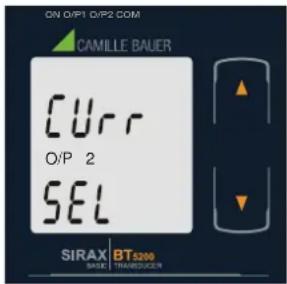
Output 2 Type confirmation
Pressing " Down" key will re-enter into Output 2 type Edit mode.
Pressing the “#p” key will set the type and advance to the Input Parameter selection (section 7.1.5).
7.1.5. Input parameter selection
7.1.5.1 End value of Input
This screen allows the user to set the End value of Input.
End value of Input can be set from 40% to 150% of set CT secondary value.

Pressing the “ Down” key will enter the “New/Change End value of Input edit” mode.
Pressing “Up” key will confirm the present value as End value of Input and advance to the Start value of Input selection (section 7.1.5.2).

New / Change End value of Input
(*Denotes that digit will be fl ashing).
Pressing the “ Down” key will scroll the value of the second digit from 0(2) through to1(7), the value will wrap from 1(7) round to 0(2) for 1A(5A) CT secondary.
Pressing the “Up” key will advance the operation to the next digit and set the second digit, in this case to “5”.
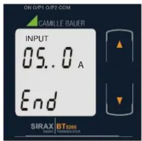
Enter New / Change End value of Input, second digit entered, prompting for third digit. (*Denotes that digit will be flashing).
Pressing the “■own” key will scroll the value of the second digit from 0 through to 9, the value will wrap from 9 round to 0.
Pressing the “■p” key will advance the operation to the next digit and set the third digit, in this case to “0”.

Enter New / Change End value of Input, third digit entered, prompting for fourth digit. (*Denotes that digit will be fl ashing).
Pressing the “ Down” key will scroll the value of the fourth digit from 0 through to 9, the value will wrap from 9 round to 0.
Pressing the “Up” key will advance the operation to the next digit and set the fourth digit, in this case to “0”.

New/changed End value of Input confirmed.
Pressing the “ Down” key will re-enter to the “New / Change End value of Input edit” mode.
Pressing the “Up” key will confirm New End value of Input and advance to the Start value of Input selection (section 7.1.5.2).
7.1.5.2 Start value of Input
This screen allows the user to set the Start value of Input. Start value of Input can be set up to 80% of End value of Input.

Pressing the “■ Down” key will enter the “New/Change
Start value of Input edit" mode.
Pressing “Up” key will confirm the present value as Start value of Input and advance to the Elbow function selection (section 7.1.5.3)

New / Change Start value of Input
(*Denotes that digit will be fl ashing).
Pressing the “Down” key will scroll the value of the second digit from 0 through to 7, the value will wrap from 7 round to 0 depending on set value of End vale of Input.
Pressing the “◆p” key will advance the operation to the next digit and set the second digit, in this case to “0”.
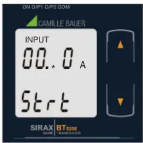
Enter New / Change Start value of Input, second digit entered, prompting for third digit. (*Denotes that digit will be fl ashing).
Pressing the “ Down” key will scroll the value of the third digit from 0 through to 9, the value will wrap from 9 round to 0 depending on set value of End vale of Input.
Pressing the “-” key will advance the operation to the next digit and set the third digit, in this case to “5”.
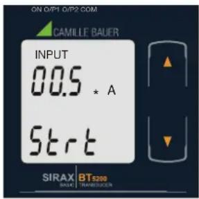
Enter New / Change Start value of Input, third digit entered, prompting for fourth digit. (* denotes that digit will be flashing).
Pressing the “ Down” key will scroll the value of the fourth digit from 0 through to 9, the value will wrap from 9 round to 0 depending on set value of End vale of Input.
Pressing the “Up” key will advance the operation to the “New / Changed Start value of Input” and set the fourth digit, in this case to “0”.

New/changed Start value of Input confirmed.
Pressing the “ Down” key will re-enter to the “New / Change Start value of Input edit” mode.
Pressing the “Up” key will confirm New Start value of Input and advance to the Elbow function selection (section 7.1.5.3).
7.1.5.3 Elbow Function selection
This screen allows the user to enable or disable Elbow function of input.
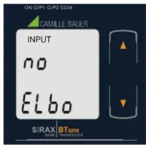
Pressing the “down” key will enter the “Selection of Elbow function of Input edit” mode and scroll the value between yes and no.
YES: Elbow function is enabled.
NO: Elbow function is disabled.
Pressing “Up” key will accept the displayed condition and advance to the Elbow value of Input selection (section 7.1.5.4) or Output parameter selection (section 7.1.6).

Elbow Function of Input confirmation
Pressing " Down" key will re-enter into Elbow function of Input Edit mode.
Pressing “◆p” key will confirm the displayed condition and advance to the Elbow value of Input selection (section 7.1.5.4) or Output parameter selection (section 7.1.6).
7.1.5.4 Elbow value of Input
This screen appears only when Elbow function is enabled.
This screen allows the user to set the Elbow value of the Input.
The Elbow value of Input can be set between 1.5% to 98.5% of Set End value of Input.

Pressing the “ Down” key will enter the “New/Change Elbow value of the Input edit” mode.
Pressing “■p” key will confirm the present value as Elbow value of the Input and advance to the Output parameter selection (section 7.1.6).

New / Change Elbow value of the Input
(*Denotes that digit will be fl ashing).
Pressing the “Down” key will scroll the value of the second digit from 0 through to 7, the value will wrap from 7 round to 0 depending on set value of End value of Input.
Pressing the “■p” key will advance the operation to the next digit and set the first digit, in this case to “4”.

Enter New / Change Elbow value of the Input, second digit entered, prompting for third digit. (*Denotes that digit will be flashing).
Pressing the “Down” key will scroll the value of the third digit from 0 through to 9, the value will wrap from 9 round to 0 depending on set value of End value of Input.
Pressing the “ p” key will advance the operation to the next digit and set the third digit, in this case to “1”.

Enter New / Change Elbow value of the Input, third digit entered, prompting for fourth digit. (* denotes that digit will be fl ashing).
Pressing the “ Down” key will scroll the value of the fourth digit from 0 through to 9, the value will wrap from 9 round to 0 depending on set value of End value of Input.
Pressing the “Up” key will advance the operation to the “New / Changed Elbow value of the Input” and set the fourth digit, in this case to “0”.

New/changed Elbow value of the Input confirmed.
Pressing the “Down” key will re-enter to the “New / Change Elbow value of the Input”.
Pressing the “■p” key will confirm New Elbow value of the Input and advance to the Output parameter selection (section 7.1.6).
7.1.6 Output parameter selection
7.1.6.1 Output 1 parameter selection
7.1.6.1.1 End value of output 1
This screen allows the user to set the End value of Output 1 (considered as DC Current).
The End value of Current Output can be set up to 20mA.

Pressing the " Down" key will enter the "New/Change
End value of the Output 1 edit" mode.
Pressing “Up” key will confirm the present value as End value of the Output 1 and advance to the Start value of Output 1 (section 7.1.6.1.2).
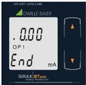
New / Change End value of the Output 1
(*Denotes that digit will be fl ashing).
Pressing the “down” key will scroll the value of the first digit from 0 through to 2, the value will wrap from 2 round to 0.
Pressing the “-p” key will advance the operation to the next digit and set the first digit, in this case to “1”.

Enter New / Change End value of the Output 1, first digit entered, prompting for second digit. (*Denotes that digit will be fl ashing).
Pressing the “down” key will scroll the value of the second digit from 0 through to 9, the value will wrap from 9 round to 0, if first digit is set to 1.
Pressing the “■p” key will advance the operation to the next digit and set the second digit, in this case to “8”.
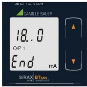
Enter New / Change End value of the Output 1, second digit entered, prompting for third digit. (*Denotes that digit will be flashing).
Pressing the “down” key will scroll the value of the third digit from 0 through to 9, the value will wrap from 9 round to 0.
Pressing the “Up” key will advance the operation to the next digit and set the third digit, in this case to “0”.

Enter New / Change End value of the Output 1, third digit entered, prompting for fourth digit. (* denotes that digit will be flashing).
Pressing the “ Down” key will scroll the value of the fourth digit from 0 through to 9, the value will wrap from 9 round to 0.
Pressing the “■p” key will advance the operation to the “New / Changed End value of the Output 1” and set the fourth digit, in this case to “0”.
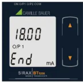
New/changed End value of the Output 1 confirmed.
Pressing the “Down” key will re-enter to the “New / Change End value of the Output 1 edit” mode.
Pressing the “Up” key will confirm New End value of the Output 1 and advance to the Start value of Output 1 (section 7.1.6.1.2).
7.1.6.1.2 Start value of output 1
This screen allows the user to set the Start value of Output 1 (considered as DC Current). Start value of Output can be set up to 20% of set End value of Output.
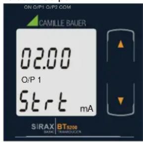
Pressing the “ Down” key will enter the “ New/Change Start value of the Output 1 edit” mode.
Pressing “Up” key will confirm the present value as Start value of the Output 1 and advance to the selection of Elbow value of Output (section 7.1.6.1.3) or Output 2 parameter selection (section 7.1.6.2)

New / Change Start value of the Output 1
(*Denotes that digit will be flashing).
Pressing the “down” key will not affect the first digit It always remains 0.
Pressing the “■p” key will advance the operation to the next digit and set the first digit, in this case to “0”.

Enter New / Change Start value of the Output 1, first digit entered, prompting for second digit. (*Denotes that digit will be fl ashing).
Pressing the “down” key will scroll the value of the second digit from 0 through to 4, the value will wrap from 4 round to 0 depending on the set End value of Output.
Pressing the “■p” key will advance the operation to the next digit and set the second digit, in this case to “0”.

Enter New / Change Start value of the Output 1, second digit entered, prompting for third digit. (*Denotes that digit will be fl ashing).
Pressing the “ Down” key will scroll the value of the third digit from 0 through to 9, the value will wrap from 9 round to 0 depending on the set End value of Output.
Pressing the “Up” key will advance the operation to the next digit and set the third digit, in this case to “0”.

Enter New / Change Start value of the Output 1, third digit entered, prompting for fourth digit. (* denotes that digit will be fl ashing).
Pressing the “ Down” key will scroll the value of the fourth digit from 0 through to 9, the value will wrap from 9 round to 0 depending on the set End value of Output.
Pressing the “Up” key will advance the operation to the “New / Changed Start value of the Output 1” and set the fourth digit, in this case to “0”.

New/changed Start value of the Output 1 confirmed.
Pressing the “ Down” key will re-enter to the “New / Change Start value of the Output 1”.
Pressing the “Up” key will confirm New Start value of the Output 1 and advance to the selection of Elbow value of Output (section 7.1.6.1.3) or Output 2 parameter selection (section 7.1.6.2)
7.1.6.1.3 Elbow value of output 1
This screen appears only when Elbow function is enabled.
This screen allows the user to set the Elbow value of Output 1 (considered as DC Current). The Elbow value can be set any value between set Start value of Output and End value of Output.

Pressing the “ Down” key will enter the “ New/Change Elbow value of the Output 1 edit” mode.
Pressing “#p” key will set the present value as Elbow value of the Output 1 and advance to the Output 2 parameter selection (section 7.1.6.2).

New / Change Elbow value of the Output 1
(*Denotes that digit will be fl ashing).
Pressing the “Down” key will scroll the value of the first digit from 0 through to 2, the value will wrap from 2 round to 0 depending on the set End value of Output.
Pressing the “■p” key will advance the operation to the next digit and set the first digit, in this case to “1”.

Enter New / Change Elbow value of the Output 1, first digit entered, prompting for second digit. (*Denotes that digit will be fl ashing).
Pressing the “down” key will scroll the value of the second digit from 0 through to 9, the value will wrap from 9 round to 0 depending on the set End value of Output.
Pressing the “■p” key will advance the operation to the next digit and set the second digit, in this case to “1”.

Enter New / Change Elbow value of the Output 1, second digit entered, prompting for third digit. (*Denotes that digit will be flashing).
Pressing the “Down” key will scroll the value of the third digit from 0 through to 9, the value will wrap from 9 round to 0 depending on the set End value of Output.
Pressing the “■p” key will advance the operation to the next digit and set the third digit, in this case to “0”.
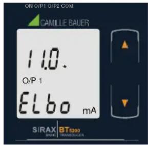
Enter New / Change Elbow value of the Output 1, third digit entered, prompting for fourth digit. (* denotes that digit will be flashing).
Pressing the “ Down” key will scroll the value of the fourth digit from 0 through to 9, the value will wrap from 9 round to 0 depending on the set End value of Output.
Pressing the “-p” key will advance the operation to the “New / Changed Elbow value of the Output 1” and set the fourth digit, in this case to “0”.
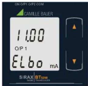
New/changed Elbow value of the Output 1 confirmed.
Pressing the “ ▶own” key will re-enter to the “New / Change Elbow value of the Output 1”.
Pressing the "■p" key will confirm New Elbow value of the Output 1 and advance to the Output 2 parameter selection(section 7.1.6.2).
7.1.6.2 Output 2 parameter selection
7.1.6.2.1 End value of output 2
This screen allows the user to set the End value of Output 2 (considered as DC Voltage). The End value of Voltage Output can be set up to 10V.

Pressing the “ Down” key will enter the “New/Change End value of the Output 2 edit” mode.
Pressing “Up” key will set the present value as End value of the Output 2 and advance to the Start value of Output selection (section 7.1.6.2.2).

New / Change End value of the Output 2
(*Denotes that digit will be fl ashing).
Pressing the “ Down” key will scroll the value of the first digit from 0 through to 1, the value will wrap from 1 round to 0.
Pressing the "Up" key will advance the operation to the next digit and set the first digit, in this case to "0".
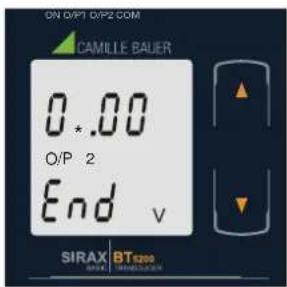
Enter New / Change End value of the Output 2, first digit entered, prompting for second digit. (*Denotes that digit will be fl ashing).
Pressing the “down” key will scroll the value of the second digit from 0 through to 9, the value will wrap from 9 round to 0, if first digit is set to 0.
Pressing the “-” key will advance the operation to the next digit and set the second digit, in this case to “9”.

Enter New / Change End value of the Output 2, second digit entered, prompting third digit. (*Denotes that digit will be fl ashing).
Pressing the "Down" key will scroll the value of the third digit from 0 through to 9, the value will wrap from 9 round to 0.
Pressing the “■p” key will advance the operation to the next digit and set the third digit, in this case to "0".
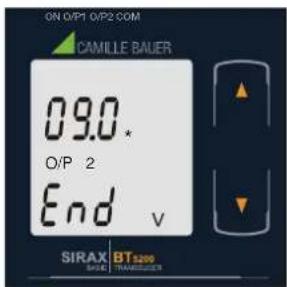
Enter New / Change End value of the Output 2, third digit entered, prompting for fourth digit. (* denotes that digit will be fl ashing).
Pressing the “ Down” key will scroll the value of the fourth digit from 0 through to 9, the value will wrap from 9 round to 0.
Pressing the “-p” key will advance the operation to the “New / Changed End value of the Output 2” and set the fourth digit, in this case to “0”.

New/changed End value of the Output 2 confirmed.
Pressing the "■own" key will re-enter to the "New / Change End value of the Output 2".
Pressing the “Up” key will confirm New End value of the Output 2 and advance to the Start value of Output selection (section 7.1.6.2.2).
7.1.6.2.2 Start value of output 2
This screen allows the user to set the Start value of Output 2 (considered as DC Voltage). Start value of Output can be set up to 20% of set End value of Output.

Pressing the “ Down” key will enter the “New/Change Start value of the Output 2 edit” mode.
Pressing “Up” key will confirm the present value as Start value of the Output 2 and advance to the Elbow value of Output selection (section 7.1.6.2.3) or exit setup menu.

New / Change Start value of the Output 2
(*Denotes that digit will be fl ashing).
Pressing the “down” key will not affect the value of first digit, it is always 0.
Pressing the “■p” key will advance the operation to the next digit and set the first digit, in every case to “0”.

Enter New / Change Start value of the Output 2, first digit entered, prompting for second digit. (*Denotes that digit will be fl ashing).
Pressing the “down” key will scroll the value of the second digit from 0 through to 9, the value will wrap from 9 round to 0, if first digit is 0.
Pressing the “■p” key will advance the operation to the next digit and set the second digit, in this case to “1”.

Enter New / Change Start value of the Output 2, second digit entered, prompting for third digit. (*Denotes that digit will be fl ashing).
Pressing the “down” key will scroll the value of the third digit from 0 through to 9, the value will wrap from 9 round to 0.
Pressing the “■p” key will advance the operation to the next digit and set the third digit, in this case to “0”.

Enter New / Change Start value of the Output 2, third digit entered, prompting for fourth digit. (* denotes that digit will be flashing).
Pressing the “ Down” key will scroll the value of the fourth digit from 0 through to 9, the value will wrap from 9 round to 0.
Pressing the “■p” key will advance the operation to the “New / Changed Elbow value of the Output 2” and set the fourth digit, in this case to “0”.
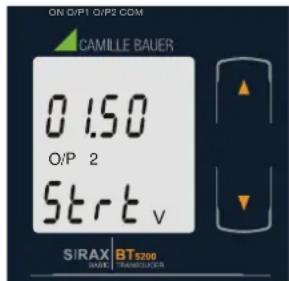
New/changed Start value of the Output 2 confirmed
Pressing the “down” key will re-enter to the “New / Change Start value of the Output 2”.
Pressing the “Up” key will confirm New Start value of the Output 2 and advance to the Elbow value of Output selection (section 7.1.6.2.3) or exit setup menu.
7.1.6.2.3 Elbow value of output 2
This screen appears only when Elbow function is enabled. This screen allows the user to set the Elbow value of Output 2 (considered as DC Voltage). The Elbow value can be set any value between set Start value of Output and End value of Output.

Pressing the “■own” key will enter the “New/Change Elbow value of the Output 2 edit” mode.
Pressing " Up" key will confirm the present value as Elbow value of the Output 2 and exit setup menu.

New / Change Elbow value of the Output 2
(*Denotes that digit will be fl ashing).
Pressing the “Down” key will scroll the value of the first digit from 0 through to 1, the value will wrap from 1 round to 0 depending on the set End value of Output.
Pressing the “-p” key will advance the operation to the next digit and set the first digit, in this case to “0”.

Enter New / Change Elbow value of the Output 2, first digit entered, prompting for second digit. (*Denotes that digit will be flashing).
Pressing the “ Down” key will scroll the value of the second digit from 0 through to 9, the value will wrap from 9 round to 0 depending the set End value of Output.
Pressing the “-” key will advance the operation to the next digit and set the second digit, in this case to “5”.

Enter New / Change Elbow value of the Output 2, second digit entered, prompting for third digit. (*Denotes that digit will be fl ashing).
Pressing the “ Down” key will scroll the value of the third digit from 0 through to 9, the value will wrap from 9 round to 0 depending the set End value of Output.
Pressing the “Up” key will advance the operation to the next digit and set the third digit, in this case to “0”.
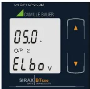
Enter New / Change Elbow value of the Output 2, third digit entered, prompting for fourth digit. (* denotes that digit will be fl ashing).
Pressing the “ Down” key will scroll the value of the fourth digit from 0 through to 9, the value will wrap from 9 round to 0 depending the set End value of Output.
Pressing the “-p” key will advance the operation to the “New / Changed Elbow value of the Output 2” and set the fourth digit, in this case to “0”.
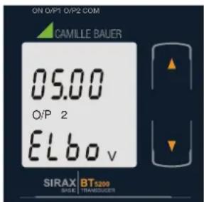
New/changed Elbow value of the Output 2 confirmed.
Pressing the “■own” key will re-enter to the “New / Change Elbow value of the Output 2”.
Pressing the “■p” key will confirm New Elbow value of the Output 2 and exit setup menu.
7.2 Programming via the programming connection and the PRKAB5000 programming cable
Follow the subsequent steps to program the SIRAX BT5200 transducer via the programming connection and the PRKAB5000 programming cable:
Step 1: DIP switch setting
The DIP switches should be configured for the desired measurement output as described in Chapter 7.4.
Step 2: Connection
Connect PC ↔ PRKAB5000 ↔ transducer according to diagram.
Please observe that the power supply for the transducer must be connected prior to programming. The installation position is irrelevant.
Step 3: Programming
Program is effected via a PC, the CB-Configurator software and the PRKAB5000 programming cable.
The CB-Confi gurator software may be downloaded via our homepage www.camillebauer.com.
The PRKAB5000 programming cable assumes the signal level and also provides the galvanic isolation between the PC connection and the programming connection at the transducer.

7.3 Programming via the RS485 (Modbus) interface
Follow the subsequent steps to program the transducer via the RS485 interface and Modbus:
Schritt 1: DIP switch setting
The DIP switches must be configured for the desired output type as described in Section 7.4.
Schritt 2: Connection
Connect the Modbus cable according to the connection diagram in Chapter 11.3. Please observe also the information in the Modbus (RS485) interface definition in Chapter 11.
Schritt 2: Programming
Program SIRAX BT5200 via the Modbus RTU interface and the CB-Configurator software. Please observe the detailed Modbus description in Chapter 11.
To change the output from current to voltage, enter the value "1".
To change the output from voltage to current, enter the value "2".
(See Section 13.2 and Table 2 Parameter No. 16 & 18 for the details).
Connect the power supply to SIRAX BT5200 before programming.
7.4. DIP Switch Setting for Output
To confi gure SIRAX BT5200 Output, programming method to be adapted along with mechanical switch setting (DIP switch setting on PCB).
Type of output (current or voltage signal) has to be set by DIP switch.
Remove Sticker for o/p Selection
| DIP Switch setting | Type of output signal |
 | load-independent current |
 | load-independent voltage |
NOTE: Black portion in above diagram indicate switch position.
8. Service, maintenance and disposal

For devices that have not been opened in the factory, no warranty or guarantee can be assumed.
8.1 Repair work and modifications
Repair work and modifications shall exclusively be carried out by the manufacturer. Do not open the housing of the device. In case of any tampering with the device, the guaranty claim shall lapse. We reserve the right of changing the product to improve it.
8.2 Calibration and new adjustment
Each device is adjusted and checked before delivery. The condition as supplied to the customer is measured and stored in electronic form.
The uncertainty of measurement devices may be altered during normal operation if, for example, the specified ambient conditions are not met.
8.3 Cleaning
The display and the operating keys should be cleaned in regular intervals. Use a dry or slightly moist cloth for this.

Damage due to detergents
Detergents may not only affect the clearness of the display but also can damage the device. Therefore, do not use detergents.
8.4 Disposal

The disposal of devices and components may only be realised in accordance with good professional practice observing the country-specific regulations. Incorrect disposal can cause environmental risks.
8.5 Return
All devices delivered to Camille Bauer Metrawatt AG shall be free of any hazardous contaminants (acids, lyes, solutions, etc.). Use original packaging or suitable transport packaging to return the device.

Damage by returning
Damages caused by improper returning, no warranties or guarantees can be given.
9. Technical data
Inputs
Rated current (In): 1 ... 5A
Current transformer primary value: 1 ... 9999A
Nominal frequency ( fn ): 45 ... 50 / 60 ... 65Hz
Rated load input voltage: < 0.6 VA at rated voltage
Overload capacity: 1.2 * l
50 * In for 1 sec. (max. 250 A)
(No text)
n permanently, 10 * X2 for 3 sec., 5 repetitions in 5 minute intervals.
Power supply
Nominal voltage: 60 ... 300V AC/DC ±5%
Consumption: ≤ 8 VA for 1 output
≤ 10 VA for 2 outputs
Measuring Output Y (Single or Optional Dual)
Output type: Load independent DC Voltage or DC Current (Onsite selectable through DIP switches
& Programming.)
Range: 0/4 ... 20 mA, 0/2 ... 10 V
Output burden with DC current output Signal: 0 ≤ R ≤ 15V/Y2
Output burden with DC voltage output Signal: Y2/(2 mA) ≤ R ≤ ∞
Current limit under overload R=0: ≤ 1.25 * Y2 with current output
≤ 60 mA with Voltage output
Voltage limit under R=∞: <1.25 * Y2 with voltage output
≤ 30 V with current output
Residual Ripple in Output signal: ≤ 1% pk-pk
Response Time: 300 ms.
Accuracy (Acc. to EN 60688)
Reference Value: Output end Value Y2 (Voltage or Current)
Basic Accuracy: 0.2*C
Factor C (The Highest value applies):
Linear characteristics:
C = 1 - Y 0Y 21 - X 0X 2 or C = 1
Bent characteristics:
C = Y 1 - Y 0X 1 - X 0 dot X 2Y 2 or C = 1
C = 1 - Y 1Y 21 - X 1X 2 or C = 1
Output characteristics:
1) Example of setting with Linear characteristics:

2) Example of setting with Bent characteristics:

X0 = Start value of input Y0 = Start value of output
X1 = Elbow value of input Y1 = Elbow value of output
X2 = End value of input Y2 = End value of output
RN = Rated value of output burden UN/IN = Nominal input voltage/current
Reference conditions for Accuracy
Ambient temperature: 23°C +/- 1°C
Pre-conditioning: 30 min acc. to EN 60688
Input Variable: Rated Voltage / Rated Current
Input waveform: Sinusoidal
Input signal frequency: 50 ... 60Hz
Auxiliary supply voltage: Rated Value ±1%
Auxiliary supply frequency: Rated Value ±1%
Output Load:
Rn = 7.5 V / Y2 ± 1% With DC current output signal.
Rn = Y2 / 1 mA ± 1% With DC Voltage output signal.
Additional Error:
Temperature influence: ± 0.2% /10 K
Safety
Protection Class: II (Protection Isolated acc. to EN 61010-1, EN 61010-2-030)
Protection: IP 40, housing according to EN 60529
IP 20, terminal according to EN 60529
Pollution degree: 2
Installation Category: III, 300V
Insulation Voltage: 50Hz,1min. (EN 61010-1) 3700V, Input versus all other circuits 3700V, Auxiliary supply versus outer surface and output 490V, Output versus output versus each other versus outer surface.
Installation Data:
Material: Lexan 940 (polycarbonate), V-0 acc. to UL94, self-extinguishing, non-dripping, free of halogen
Mounting position: Rail mounting / wall mounting
Weight: Approx. 0.4kg
Connection Terminal
Connection Element: Conventional Screw type terminal with indirect wire pressure
Permissible cross section
of the connection lead: ≤ 4.0 mm single wire or 2 x 2.5 mm Fine wire
Environmental
Nominal range of use: 0 °C ... 23 °C ... 45 °C (usage Group II)
Storage temperature: -40ircC to 70ircC
Relative humidity of annual mean: ≤ 75%
Altitude:
2000m
max
Ambient tests:
Rate of frequency sweep: 1 octave/minute
Number of cycles: 10, in each of the three axes
EN 60068-2-7: Shock
Acceleration: 3 x 50g
3 shocks in each direction
EN 60068-2-1/-2/-3
Cold, Dry, Damp heat
EN 61000-4-2/-3/-4/-5/-6 EN 55011
Electromagnetic compatibility
10. Dimensional drawings


11. Interface Definition Modbus RTU
SIRAX BT5200 supports Modbus RTU protocol (RS485).
The permissible address range for the BT5200 is between 1 and 247. Broadcast Mode (address 0) is not allowed.
The maximum latency time of an BT5200 is 200ms i.e. this is the amount of time that can pass before the first response character is output.
After sending any query through software (of the Master), it must allow 200ms of time to elapse before assuming that the BT5200 is not going to respond. If slave does not respond within 200 ms, Master can ignore the previous query and can issue fresh query to the slave.
11.1 Modbus functions
Following code functions are provide:
| Function code | Function Address | |
| 03 Read holding registers 40001 to 40040 | ||
| 04 Read input registers 30001 to 30002 | ||
| 16 Presets multiple registers 40001 to 40040 | ||
Example of read out measurement
Query:
| Device address Function code Start address Nr. of register CRC | |||
| 0x01 0x04 0x0006 | 0x0002 | 0x91CA | |
Response:
| Device address | Function code | Nr. of databytes | Databytes 0 ... 3 | CRC |
| 0x01 | 0x04 0x04 | 0x3C52C75D | 0xC5CC |
Example of set slave address to 2
Query:
| Device address | Function code | Start address | Nr. of register | Nr. of bytes | Databytes 0...3 | CRC |
| 0x01 | 0x10 | 0x000E | 0x0002 | 0x04 | 0x40000000 | 0x67E3 |
Response:
| Device address | Function code | Start address | Nr. of register | CRC |
| 0x01 | 0x10 | 0x000E | 0x0002 | 0x200B |
Exception Cases: An exception code will be generated when BT5200 receives ModBus query with valid parity and error check but which contains some other error (e.g. Attempt to set floating point variable to an invalid value). The response generated will be "Function code" + 0x80.
| 01 | Illegal function | The function code is not supported. |
| 02 | Illegal data address | Attempt to access an invalid address or an attempt to read or write part of a floating point value. |
| 03 | Illegal data value | Attempt to set a floating point variable to an invalid value. |
11.2 Data types
All information are displayed as 32-bit float. There is no representation for floating point numbers in the Modbus specification. But as a matter of principle any desired data structure can be casted to a sequence of 16Bit registers.
The IEEE 754 standard as the most often used standard for the representation of floating numbers is applied.
• The first register contains the bits 16 – 31
• The second register contains the bits 0 – 15
32-Bit Float (Real32)
| 31 | 30 | 23 | 22 | 0 |
| exponent | mantissa | |||
| sign | ||||
| 0x3C52 | 0xC75D | |||||||||||||||||||||||||||||||||
| 0 | 0 | 1 | 1 | 1 | 1 | 0 | 0 | 0 | 1 | 0 | 1 | 0 | 0 | 1 | 0 | 1 | 1 | 0 | 0 | 0 | 1 | 1 | 1 | 0 | 1 | 0 | 1 | 1 | 1 | 0 | 1 | |||
| + | Exponent: 120-127=-7 | Mantisse=1.00111100010100101100011101011101=1.64670908451080325424989 | ||||||||||||||||||||||||||||||||
Measuring value I = 1.64670908451080325424989 * 2 -7 = 0.012864915 A
11.3 Modbus Register
| Address (Register) | Name | Read/Write | Description | |||||||
| 30007 Current R Input current (RMS) | ||||||||||
| 40001 -- - | ||||||||||
| 40003 Mode selection R/W This is used to select the Mode of operation.Normal mode = 1Simulation mode = 2 | ||||||||||
| 40005 -- - | ||||||||||
| 40007 -- - | ||||||||||
| 40009 -- - | ||||||||||
| 40011 Primary current R/W This address allows the user to read and write the CT Primary value. The maximum stable value is 9999. | ||||||||||
| 40013 | Secondary current | R/W | This address allows the user to read and write the CT secondary value in range between 1A to 5A. | |||||||
| 40015 Device address R/W This address is used to set the Device address between 1 to 247. | ||||||||||
| 40017 RS 485 Set up R/W This address is used to set the Baud rate, Parity and number of stop bits. | ||||||||||
| 1 | ||||||||||
| 2 | ||||||||||
| 3 | ||||||||||
| 4 | ||||||||||
| 5 | ||||||||||
| 6 | ||||||||||
| 7 | ||||||||||
| 40019 Password | R This address is used to set and reset the password.Password protection off = 1Password protection on = 0 | |||||||||
| W | When active password protection, write first the old password and then the new password.Password protection off = 0000New Password = 1234 (Valid range of the password is 0000-9999) | |||||||||
| 40023 -- - | ||||||||||
| 40025 -- - | ||||||||||
| 40027 Simulation output O/P1 | R/W This address is used to set the simulation output O/P1 to 10% of output by writing 1000 and 100% of output by writing 10000. | |||||||||
| 40029 Simulation output O/P2 | R/W This address is used to set the simulation output O/P2 to 10% of output by writing 1000 and 100% of output by writing 10000. | |||||||||
| 40031 Analog O/P1 | R/W This address is used to set the Analog O/P1 as Voltage/Current.Voltage = 1Current = 2 | |||||||||
| 40033 -- - | ||||||||||
| 40035 Analog O/P 2 | R/W This address is used to set the Analog O/P2 as Voltage/Current.Voltage = 1Current = 2 | |||||||||
| 40037 -- - | ||||||||||
| 40039 -- - | ||||||||||



- Operating Instructions
- SIRAX BT5200
- Legal information
- Warning notices
- Qualifi ed personnel
- Intended use
- Disclaimer of liability
- Feedback
- Table of content
- Introduction 4
- Safety notes .... 4
- Device overview .... 5
- Mechanical mounting .... 5
- Electrical connections ...... 6
- Commissioning 7
- Programming 9
- Service, maintenance and disposal 27
- Technical data 28
- Dimensional drawings....30
- Interface Definition Modbus RTU ....30
- Introduction
- Purpose of this document
- Scope
- Required knowledge
- Scope of supply
- Further documents
- Safety notes
- Device overview
- Mechanical mounting
- Mounting
- Demounting of the device
- Electrical connections
- General safety notes
- Please observe that the data on the type plate must be adhered to!
- Cross sections and tightening torques
- Inputs
- Power supply
- Connection Diagram
- Modbus interface RS485
- Commissioning
- Operating the device
- LED indication
- Input and output screens
- Programming
- Programming via Front LCD & Two keys
- Password Protection
- Password Verification
- Password Set/Confirmed
- Password Incorrect.
- New/Change Password
- New / Change Password
- New/changed Password confirmed
- Current Transformer parameter selection
- Current Transformer primary value
- New / Change CT Primary value
- Current Transformer secondary value
- New / Change CT Secondary value
- New/changed CT Secondary value confirmed.
- Communication Parameter Selection :
- Address Setting
- New/changed Address value
- New/changed Address value confirmed.
- RS 485 Baud Rate
- RS 485 Baud Rate confirmation
- RS 485 Parity Selection:
- RS 485 Parity confirmation
- Output Type Selection
- Output 1 Type selection
- Output 1 Type confirmation
- Output 2 Type Selection
- Output 2 Type confirmation
- Input parameter selection
- End value of Input
- New / Change End value of Input
- New/changed End value of Input confirmed.
- Start value of Input
- New / Change Start value of Input
- New/changed Start value of Input confirmed.
- Elbow Function selection
- Elbow Function of Input confirmation
- Elbow value of Input
- New / Change Elbow value of the Input
- New/changed Elbow value of the Input confirmed.
- Output parameter selection
- Output 1 parameter selection
- End value of output 1
- New / Change End value of the Output 1
- New/changed End value of the Output 1 confirmed.
- Start value of output 1
- New / Change Start value of the Output 1
- New/changed Start value of the Output 1 confirmed.
- Elbow value of output 1
- New / Change Elbow value of the Output 1
- New/changed Elbow value of the Output 1 confirmed.
- Output 2 parameter selection
- End value of output 2
- New / Change End value of the Output 2
- New/changed End value of the Output 2 confirmed.
- Start value of output 2
- New / Change Start value of the Output 2
- New/changed Start value of the Output 2 confirmed
- Elbow value of output 2
- New / Change Elbow value of the Output 2
- New/changed Elbow value of the Output 2 confirmed.
- Programming via the programming connection and the PRKAB5000 programming cable
- Step 1: DIP switch setting
- Step 2: Connection
- Step 3: Programming
- Programming via the RS485 (Modbus) interface
- Schritt 1: DIP switch setting
- Schritt 2: Connection
- Schritt 2: Programming
- DIP Switch Setting for Output
- Service, maintenance and disposal
- Repair work and modifications
- Calibration and new adjustment
- Cleaning
- Damage due to detergents
- Disposal
- Return
- Damage by returning
- Technical data
- Inputs
- Power supply
- Measuring Output Y (Single or Optional Dual)
- Accuracy (Acc. to EN 60688)
- Output characteristics:
- Reference conditions for Accuracy
- Additional Error:
- Safety
- Installation Data:
- Connection Terminal
- Environmental
- Ambient tests:
- Dimensional drawings
- Interface Definition Modbus RTU
- Modbus functions
- Example of read out measurement
- Example of set slave address to 2
- Data types
Brand : Camille Bauer
Model : SIRAX BT5200
Category : Energy meter