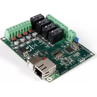
VM204 - Smart Home VELLEMAN - Free user manual and instructions
Find the device manual for free VM204 VELLEMAN in PDF.


| Product Type | Smart Home Controller |
| Brand | Velleman |
| Model | VM204 |
| Dimensions (L x W x H) | 80 x 60 x 20 mm |
| Weight | 50 g |
| Power Supply | 5V DC via USB (cable included) |
| Power Consumption | 0.5 W (standby), 1 W (active) |
| Operating Temperature | 0°C to 40°C |
| Connectivity | Wi-Fi 802.11 b/g/n (2.4 GHz), Zigbee |
| Compatibility | Works with Amazon Alexa, Google Assistant |
| Main Functions | Home automation control, remote monitoring, scheduling |
| Maintenance | Keep firmware updated via app |
| Cleaning | Wipe with dry cloth, avoid liquids |
| Safety | Do not expose to water or high humidity |
| Spare Parts | USB cable (standard) |
| Reparability | Contact Velleman support for repairs |
| Certifications | CE, RoHS |
| Warranty | 2 years |
| Package Contents | VM204 unit, USB cable, quick start guide |
Frequently Asked Questions - VM204 VELLEMAN
User questions about VM204 VELLEMAN
0 question about this device. Answer the ones you know or ask your own.
Ask a new question about this device
Download the instructions for your Smart Home in PDF format for free! Find your manual VM204 - VELLEMAN and take your electronic device back in hand. On this page are published all the documents necessary for the use of your device. VM204 by VELLEMAN.
USER MANUAL VM204 VELLEMAN
USER MANUAL DECEMBER 2016
ETHERNET RELAY CARD
VM204
natural_image
Green printed circuit board with various electronic components and connectors (no visible text or symbols)Table of contents
Introduction
3
1. Connecting the VM204
4
1.1 Using the iOS and Android app for the first time 4
1.2 Using the PC application for the first time 8
2. Controlling the VM204 10
2.1 Relay 10
2.2 Input 11
2.3 Analog input 12
2.4 API 13
2.5 Factory reset 13
3. Editing the VM204
14
3.1 Credentials 14
3.2 Network settings 14
3.3 Email settings 15
3.4 I/O settings 15
3.5 Notification settings 17
3.6 API 18
3.7 API references 18
3.8 About 18
4. Upgrading the firmware
21
Let's get started!
CAUTION

Do not connect external voltage to the inputs because this will destroy the VM204!

Take care not to exceed the relay rated voltage and current!

Changing the credentials will reboot the VM204 and all relays will be deactivated, make sure no machines are connected while doing this!

If you click the save and reboot button, the VM204 will deactivate all relays. The webserver will restart with the new port and/or IP so the current webpage will not work. Browse to the new page with the correct port and/or IP.
Introduction to the VM204
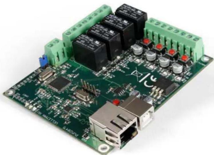
The VM204 is an Ethernet controlled board with 4 relay contacts, 4 digital inputs and 1 analog input. You can connect these I/O's to different devices and control or check them from anywhere you like using your PC, smartphone or tablet. The VM204 can also send email notifications when the status of an input changes and features an embedded webserver.
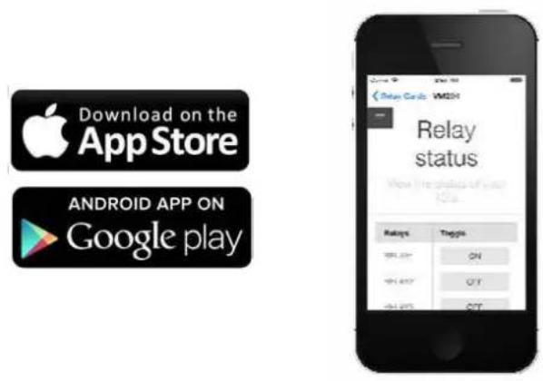
If you wish to control your VM204 with your smartphone or tablet, free apps are available for Android® and iOS®.

1. Connecting the Ethernet relay card or VM204
First of all make sure you have a DHCP enabled network. If you don't know what DHCP is then don't worry, a regular home network is usually DHCP enabled.
⚠️ Please make sure to upgrade your firmware to version 1.1. Download here:
http://www.vellemanprojects.eu/support/downloads/?code=VM204
Please see section 4 of the user manual for more information on upgrading the firmware.
Connect both the Ethernet cable and the USB cable into the VM204.
Afterwards, connect the Ethernet cable to your router and the USB cable to a USB power plug or USB port. The red and yellow LEDs should now be blinking. If the green led is on, you can proceed to the next instruction.
To continue, download the iOS- or Android app via the links below:
iOS: www.appstore.com/vm204
Android: https://play.google.com/store/apps/details?id=be.velleman.VM204_2
Or install the PC application via the link below:
http://www.velleman.eu/downloads/files/downloads/vm204setup.zip
1.1 Using the iOS and Android app for the first time
First, make sure your smartphone or tablet is connected to the same network/Wi-Fi as the VM204. Then open the app and follow these simple steps to add your personal VM204 to your app:
- Add a new relay card by tapping the <+> button.

- Tap the
button below to search for your VM204.

- Your VM204 should pop up in the list, be sure to select it.

4. Fill out the default credentials:
Login: admin
Password: VM204 (capital letters).
We will explain how you can change your credentials later on.

- Continue by tapping the
button, there should be a Relay card added to the list now.
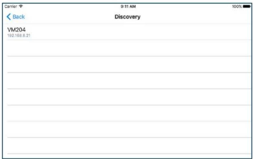
- Tap on the name of your newly added relay card (standard name is VM204) to go to the control page of your VM204. Head forward to chapter 2. Controlling the VM204 and discover all the possibilities.
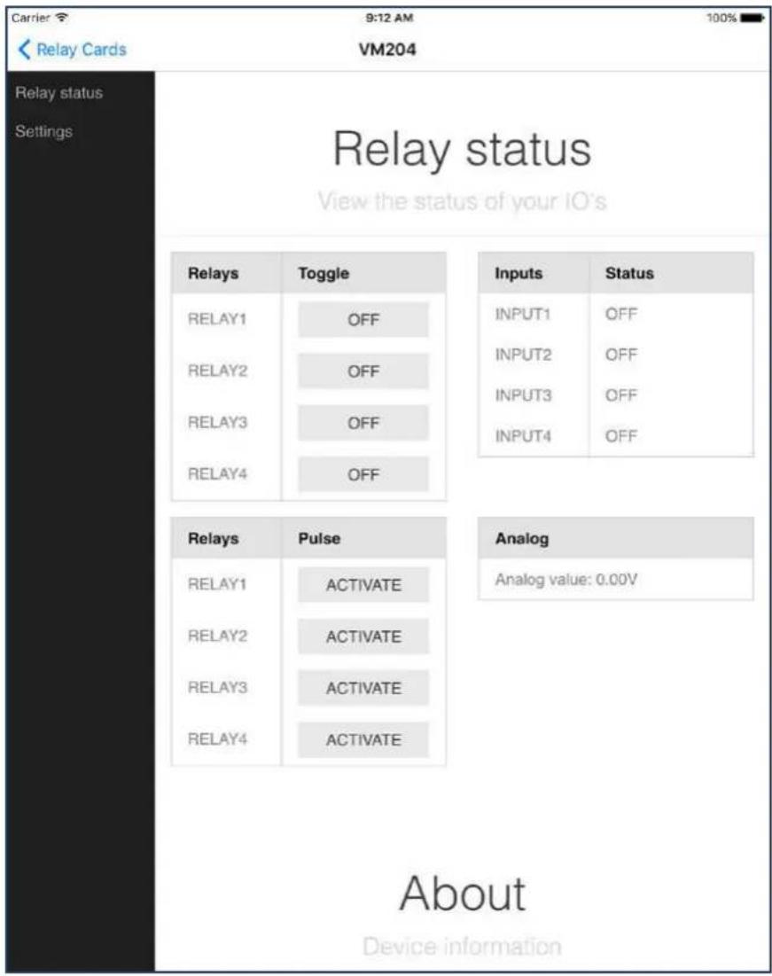
- To edit your relay card, go back and slide over the name of your relay card to the left (for iOS) or long press the name of your relay card (for Android) and tap
. If you wish to delete your relay card, tap .

1.2 Using the PC application for the first time
If you choose to use your PC to control the VM204, make sure your PC is connected to the same network/Wi-Fi as the VM204. Then open the VM204 discovery application and follow these simple steps to connect your VM204:
- Click the
button.

- A new row will be added. Click on your device and a webpage should open.
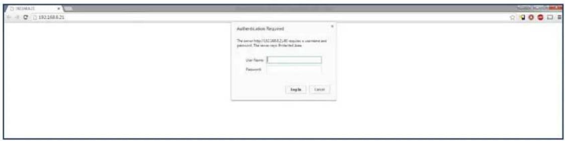
- Fill out the default credentials:
Login: admin
Password: VM204 (capital letters).
We will explain how you can change your credentials later on.
- You now have access to the VM204 and will be able to control it. Head to the next chapter to discover the possibilities.
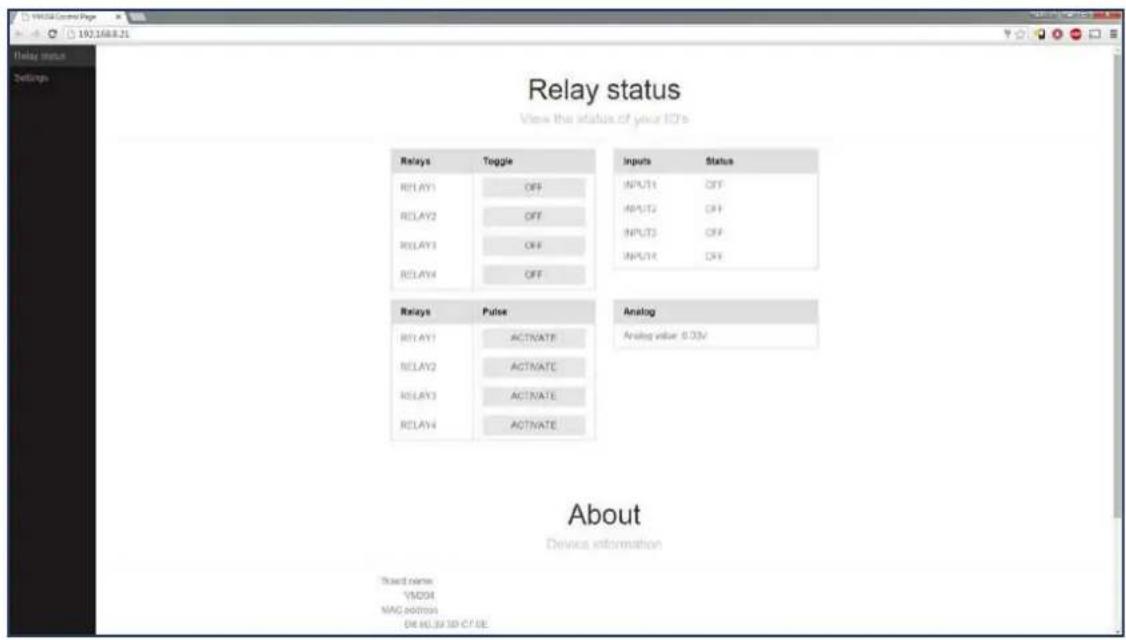
2. Controlling the VM204
The VM204 has 3 different Input/Outputs: relays, inputs and an analog input. By using these I/Os, you can read statuses from sensors or switches via the inputs and control devices via the relays.
2.1 Relay
A relay (electro-mechanical switch) is used to switch external connected electrical devices.
An external supply is used that suits the connected device. The relay does not generate any power; therefore it is a dry contact.

TENTION
Take care not to exceed the relay rated voltage and current!
Connect a relay to a device as shown in de diagram below:
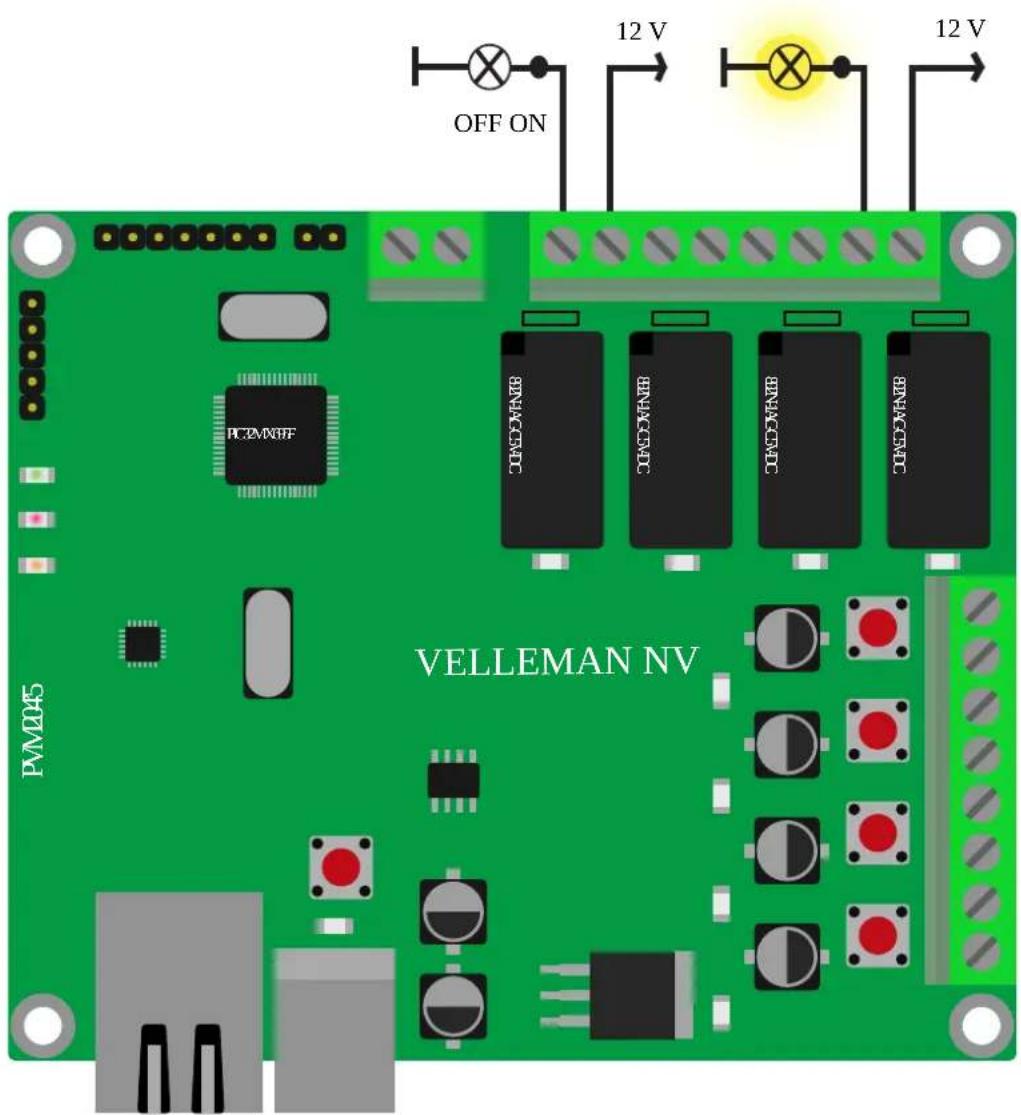
Controlling the relay
You can control the relays you connected via the Main page of your control panel by tapping/clicking on the
The toggle buttons represent the current state of the relay. This means that if you see ON in the button, the relay is closed and is passing through current. If the button says OFF the relay is open and is not passing any current.

2.2 Input
Inputs are used to sense whether 2 terminals are connected to each other or not. These digital inputs accept dry contact or open collector.
ATTENTION
Do not connect external voltage to the inputs because this will destroy the VM204!
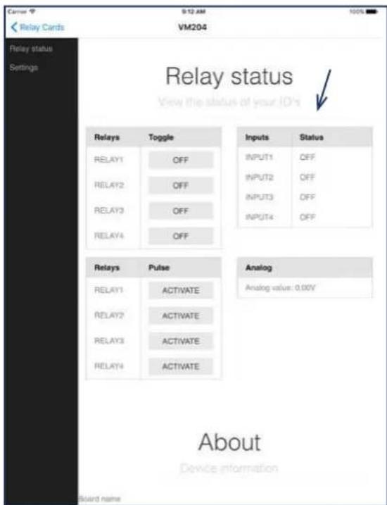
If the 2 wires are not connected, the status of the input will be OFF, if the 2 wires are connected the status of the input will be ON.

The status of the inputs can also be checked on the main page, here:
2.3 Analog input
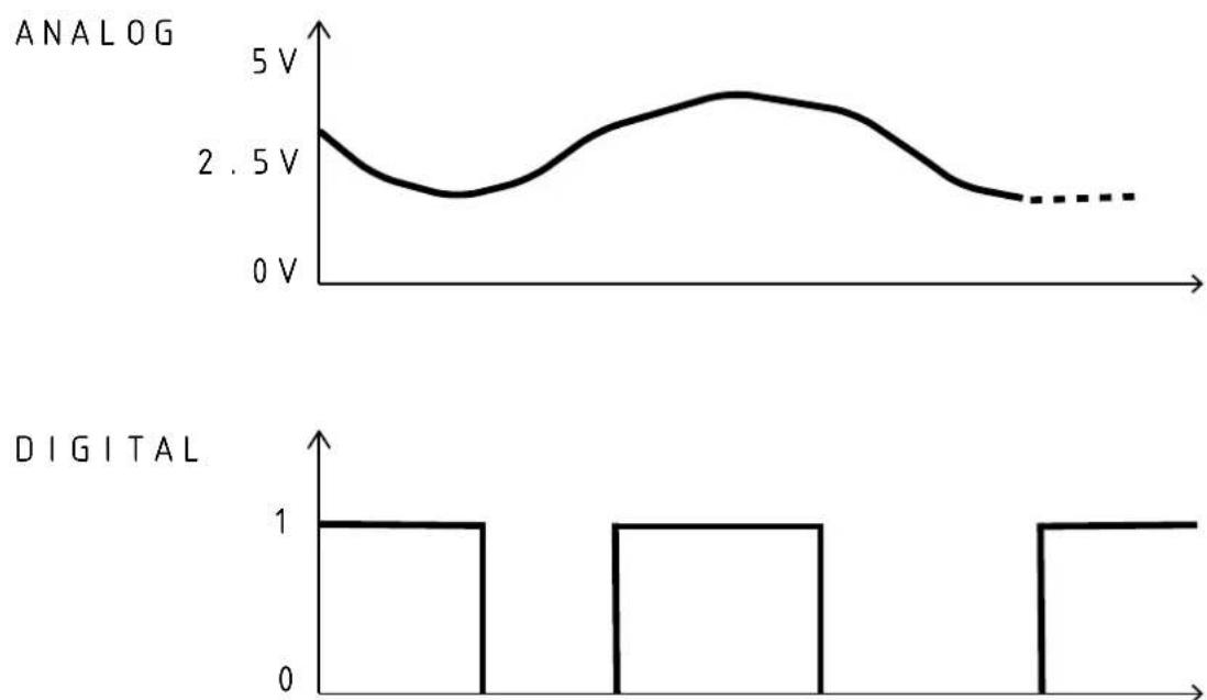
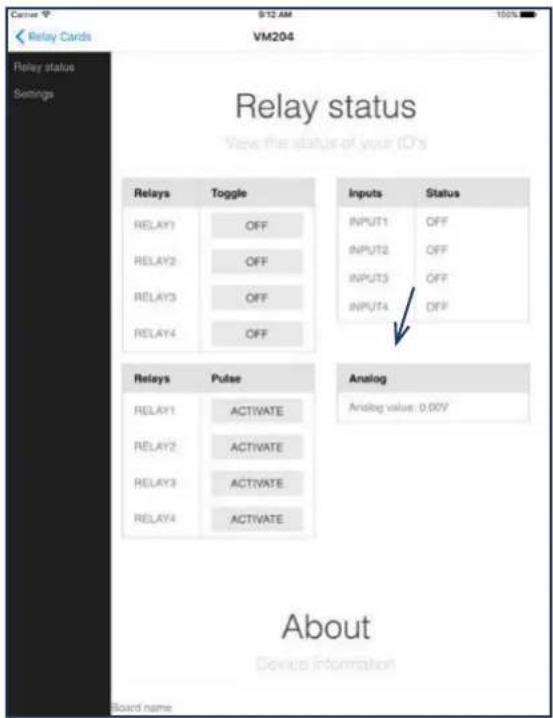
The analog input is a special kind of input which does not read 1's and 0's but measures the exact voltage on the input. This means you can read sensors like a thermistor or an anemometer. The grafic below shows an example of an analog and a digital signal:
The analog value can be read from the main page, here:
2.4 API (Application Programming Interface)
The VM204 has an API which makes it easier for developers to control the relay card from their own application. The complete reference for accessing the API calls can be found in 'Settings' and then 'API Reference'.
2.5 Factory reset
To return to the default settings, follow these steps:
- First, make sure the power of the card is on (the yellow and red LEDs should be on).
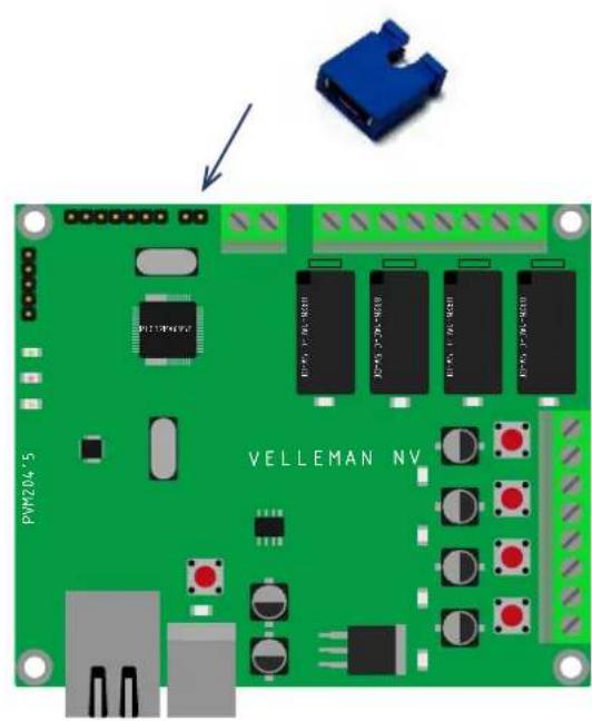
- Place a shunt (not incl.) on the factory reset pins (2 pins) next to the analog input. If you do not have a shunt, short the two pins with a conductive piece of metal/wire.
- Unplug the USB cable (the yellow and red LEDs should now be off).
- Remove the blue shunt or conductive piece.
- Plug the USB cable back in.
Make sure you follow the correct order!

natural_image
Green printed circuit board with electronic components and a blue plastic housing (no readable text or symbols)3. Editing the VM204
To start editing the VM204, go to 'Settings' in the left menu bar.
3.1 Credentials

ARNING
changing the credentials will reboot the VM204 and all relays will be deactivated, make sure no machines are connected while doing this!
If you want to control or edit the VM204, you must first be authenticated. The default Login and password are still: Login: admin
Password: VM204 (capitals)
If you want to change the credentials go to 'Settings' then 'Authentication'. Fill out the form and click or tap

3.2 Network settings
In general, the network settings are set up to suit your convenience and can remain unadjusted. If however you are an experienced user, we created an opportunity for you to adjust the network configuration of the VM204.
If you want to change the port*
which the webserver is running on, you can change it by going to 'Settings' and then 'Network'. Now you can enter a new port in the web interface subsection. Click or tap

ARNING
If you click the save and reboot button, the VM204 will deactivate all relays. The webserver will restart with the new port and/or IP so the current webpage will not work. Browse to the new page with the correct port and/or IP.

3.3 Email settings
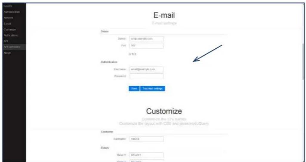
The VM204 is capable of sending emails even with SSL/TLS encryption. This makes the VM204 compatible with Gmail, Outlook, etc... In the email settings, you can enter the email address from which emails will be sent via the VM204.
Go to 'Settings' in the left menu bar and scroll down to the Email section. Fill out the credentials of your ISP or any webmail service and press
You can test your credentials by clicking
3.4 IO settings
It is possible to customize the IO names, set the Pulse time of the Relays, customize the look and feel and even the functionality of the website.
Changing the IO names
The name of the VM204 and all the relays and inputs can be changed by going to 'Settings', 'Customize' and then fill out a new name in the name field of either the card name, relays or inputs (blue arrows). Don't forget to click
A specific card name makes it easy to browse to the relay card in your local network without remembering the IP address. It also makes it easy to distinguish multiple cards in the same network.

If you give each relay and input a different name, it's easy to remember what the relay is controlling or what the input is reading. For example 'lights bathroom' or 'doorbell'. These names will also be used when sending e-mails from the VM204.
Set the Pulse time
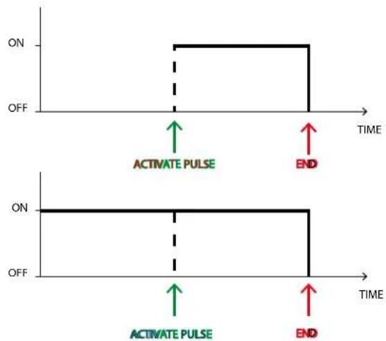
Another customizable feature is activating the relays for a certain amount of time. This is the pulse feature. The length of the pulse can be set in the 'Pulse' section using seconds (as shown in the picture above, red arrow).
The pulse can work in two ways:
The first way, as shown in the first diagram is when you activate the pulse when the relay was in the OFF state. The relay will be in the ON state for the amount of time that you have set.
The second way is when you activate the pulse while the relay is already in the ON state. The relay will remain in the ON state for the amount of time that you have set.
The look, feel and functionality
The two next fields in the Custom section are 'Custom js' and 'Custom css'. They allow you to add a URL to Javascript or a CSS file, which can alter the looks and functionality of the website.
3.5 Notifications
The 'Notification' settings allow you to enable and disable email notifications for different actions. When an action is triggered an e-mail will be sent from the account you gave up in your email settings.
First make sure you enter the correct email addresses to which you want to send the notifications (blue arrow). If you want to enter more then one email address, type a ';' inbetween the addresses with no spaces. For example: alice@email.com;trudy@email.com;john@email.com
To disable the email notifications, simply uncheck the 'Enabled' box (red arrow). Don't forget to save!

Actions
There are 4 different actions to which you can enable an email notification. You can choose one or more actions by opening the notification list (as shown in the picture) and selecting the actions you want to get notified of.

We will now explain each action in detail.
A. Input rising:
An email will be sent if the corresponding Input transfers from a low to a high (or from off to on) state. For example: when the doorbell goes off. This can be done for each individual input.

flowchart
graph TD
    A["OFF"] --> B["ON"]
    B --> C["OFF = OPEN"]
    C --> D["EMAIL ON = CLOSED"]
    D --> E["OFF = OPEN"]
    style D stroke:#000,stroke-width:2px
    style E stroke:#000,stroke-width:2px
B. Input falling:
An email will be sent if the corresponding Input transfers from a high to a low (or from on to off) state. For example: when the heating is turned off. This can be done for each individual input.

flowchart
graph TD
    A["OFF = OPEN"] --> B["ON = CLOSED"]
    B --> C["OFF = OPEN"]
    style A fill:#f9f,stroke:#333
    style B fill:#ccf,stroke:#333
    style C fill:#cfc,stroke:#333
    note right of C EMAIL
    note left of A OFF ON OFF
    note right of B ON ON OFF
    note right of C OFF OPEN
    note right of B ON OPEN
    note right of C OFF OPEN
C. Boot:
When the VM204 is powered up and has an IP, the card will send an e-mail notifying you it started up. For example: when the power is rebooted after a power failure.
D. Analog threshold:
When the analog value reaches a specified value, it will send an email. If the analog value goes below the threshold and then above, it will send an email again. For example: if the temperature outside drops below 0^ C. The analog threshold is in this case 0.

line
| TIME | TEMPERATURE | |------|-------------| | EMAIL | 0 | | | Analog TRESHOLD | | | ANALOG TRESHOLD | | | ANALOG TRESHOLD | | | ANALOG TRESHOLD | | | ANALOG TRESHOLD | | | ANALOG TRESHOLD | | | ANALOG TRESHOLD | | | ANALOG TRESHOLD | | | ANALOG TRESHOLD | | | ANALOG TRESHOLD | | | ANALOG TRESHOLD | | | ANALOG TRESHOLD | | | ANALOGTRESHOLD | | | ANALOGTRESHOLD | | | ANALOGTRESHOLD | | | ANALOGTRESHOLD | | | ANALOGTRESHOLD | | | ANALOGTRESHOLD | | | ANALOGTRESHOLD | | | ANALOGTRESHOLD | | | ANALOGTRESHOLD | | | ANALOGTRESHOLD | | | ANALOGTRETHOLO | | | ANALOGTRETHOLO | | | ANALOGTRETHOLO | | | ANALOGTRETHOLO | | | ANALOGTRETHOLO | | | ANALOGTRETHOLO | | | ANALOGTRETHOLO | | | ANALOGTRETHOLO | | | ANALOGTRETHOLO | | | ANALOGTRETHOLO |You can set the analog treshold value in the 'Alarm value' box after you select this action in the list (see picture below). The alarm value must be between 1 and 1024. This value can be calculated by multiplying your voltage value times 155. For example if your voltage value is 3.3V then the calculation is: 3.3V * 155 = 511.5 => 512 . Floating-point numbers are not valid so round your value up or down. The maximum voltage that can be sensed is 6.6V (=1024).

3.6 API
The API key allows the user to login to the relay card without the credentials but with only a single key. This key is only valid when accessing the API urls that can be found in the API Reference page which will help you to control the relay card from your own programme.
3.7 API reference
The API reference shows you a list of all commands and requests that can be made with your own programme.
3.8 About
This section shows you the device information such as Board name, MAC address, System up-time, Firmware version, Analog max. value and Analog min. value.
4. Upgrading the firmware
In case there is new firmware available or if there should be any problems with your Ethernet relay card, you can always reinstall/upgrade the firmware by following these steps.
-
Before we start, it is important to copy/remember/note your IP address for later on. You can find this either in the 'settings' page of the VM204 app or in the IP column in the discovery software. You won't be able to do this after step 3.
-
Go to the download page of the VM204 on the Velleman website: http://www.velleman.eu/support/downloads/?code=VM204
Download the 'VM204 Firmware V1.1'.
- Mount a shunt onto the factory reset pins (2 pins), located next to the analog input. If you do not have a shunt, short the two pins with a conductive piece of metal/wire.
-
Power cycle the card by first unplugging the USB cable and then inserting it again.
-
Open the VM204 FW application which is included in the VM204 PC software. You can download this PC software on the product page here:
http://www.velleman.eu/support/downloads/?code=VM204

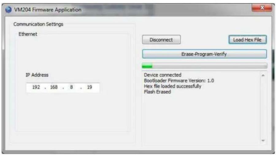
- Hopefully you remembered your IP address! Copy it into the 'IP Address' field and press
. Normally, you should see 'device connected'.

- Press
and open the Hex file you downloaded during step 2.

- Press
, this will first reprogram the VM204 and then restart it.

velleman®
ORDERCODE: VM204
REVISION: HVM204'1

- ETHERNET RELAY CARD
- Table of contents
- Introduction
- Connecting the VM204
- Controlling the VM204 10
- Editing the VM204
- Upgrading the firmware
- CAUTION
- Introduction to the VM204
- Connecting the Ethernet relay card or VM204
- Using the iOS and Android app for the first time
- Fill out the default credentials:
- Using the PC application for the first time
- Controlling the VM204
- Relay
- TENTION
- Controlling the relay
- Input
- ATTENTION
- Analog input
- API (Application Programming Interface)
- Factory reset
- Credentials
- ARNING
- Network settings
- Email settings
- IO settings
- Changing the IO names
- Set the Pulse time
- The look, feel and functionality
- Notifications
- Actions
- Input rising:
- Input falling:
- Boot:
- Analog threshold:
- API
- API reference
- About
- velleman®
Brand : VELLEMAN
Model : VM204
Category : Smart Home