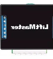
TLS1CARD - Door automation LiftMaster - Free user manual and instructions
Find the device manual for free TLS1CARD LiftMaster in PDF.


| Product Type | Garage Door Opener Remote Control Card |
| Brand | LiftMaster |
| Model | TLS1CARD |
| Dimensions | Approximately 2.5 x 1.5 x 0.5 inches |
| Weight | 0.5 oz |
| Power Source | 12V battery (CR2032 or similar) |
| Operating Frequency | 315 MHz or 390 MHz (depending on model) |
| Range | Up to 100 feet (open field) |
| Compatibility | LiftMaster garage door openers with Security+ 2.0 or MyQ technology |
| Number of Channels | Single button |
| Programming | Via learn button on garage door opener |
| Main Functions | Open, close, and stop garage door |
| Care & Maintenance | Keep dry, replace battery when low, clean with soft cloth |
| Safety | Rolling code technology for secure operation |
| Spare Parts | Battery (CR2032) and packaging |
| Repairability | Not user-serviceable; replace entire unit if malfunctioning |
| General Information | Designed for convenient wireless control of compatible LiftMaster openers |
| Certifications | FCC, Industry Canada compliant |
| Warranty | 1 year limited warranty |
| Battery Life | Approximately 2 years typical usage |
Frequently Asked Questions - TLS1CARD LiftMaster
User questions about TLS1CARD LiftMaster
0 question about this device. Answer the ones you know or ask your own.
Ask a new question about this device
Download the instructions for your Door automation in PDF format for free! Find your manual TLS1CARD - LiftMaster and take your electronic device back in hand. On this page are published all the documents necessary for the use of your device. TLS1CARD by LiftMaster.
USER MANUAL TLS1CARD LiftMaster
Commercial Door Operators

natural_image
Line drawing of a rectangular electronic device with ports and connectors (no text or symbols)TLS1CARD
TIMER LIGHT STATUS OPTION CARD
The TLS1CARD has different configuration modes that determine how the TLS1CARD will function.
| MODE | COMPARABLE | MODIFICATION | DESCRIPTION |
| TCP Mode 1 | 90-T1, 90-515774, or RDGRNCARDAdjustable Pre-WarningR2 output on at fully open and at open mid-stopR3 output on while closing only | 3 relay outputs (R1, R2, and R3) with optional flashing for R1R1 output on during Pre-Warning, while in motion, and at an undefined stopped position | |
| TCP Mode 2 | 90-T2 | 3 relay outputs (R1, R2, and R3) | Adjustable Pre-WarningR1 output on during Pre-Warning onlyR2 output on at fully openR3 output on only when a special input to open has been used to open the door which does not activate the Timer-to-Close |
| TCP Mode 3 | 90-T4 | 3 relay outputs (R1, R2, and R3)Adjustable Pre-WarningR1 output on during Pre-Warning onlyR2 output on at fully open and at open mid-stopR3 output on while in motion | |
| TCP Mode 4 | 90-RGLFCIR or 90-HDFLASH2 | 2 relay outputs (R1, R2) with optional flashing for R1Adjustable Pre-WarningR1 output on during Pre-Warning and while closingR2 output on at fully open | |
| TCP Mode 5 | 90-T3 | 3 relay outputs (R1, R2, and R3) | Adjustable Pre-WarningR1 output on at all times except fully open and fully closedR2 output on at fully openR3 output on only when a special input to open has been used to open the door which does not activate the Timer-to-Close |
| TC Mode 1 | 90-L3FLASH | 3 relay outputs (R1, R2, and R3) with optional flashing for R1R1 output on while in motionR2 output on at fully open and at open mid-stopR3 output on at fully open, open mid-stop, and at an undefined stopped position | |
| SP Mode 1 | 90-42104 | This mode allows a second set of external, track mounted limits to act as primary or backup for the operator's open, close, and safety limits.NOTE: It is not required that all three inputs have a switch connected to the TLS1CARD. Either the external close, external safety, external open, or all three may be used. | |
WARNING WARN
To prevent possible SERIOUS INJURY or DEATH from electrocution, disconnect electric power to operator BEFORE installing.
ALL electrical connections MUST be made by a qualified individual.
WARNING WARNING
To prevent possible PROPERTY DAMAGE, ACCIDENTAL ENTRAPMENT, SEVERE INJURY, or DEATH:
- Disconnect power to the operator and fully open or close the door BEFORE installing ANY entrapment protection devices.
-
LiftMaster Monitored Entrapment Protection (LMEP) devices MUST be installed for all wiring types except constant pressure to close. However, LiftMaster Monitored Entrapment Protection (LMEP) devices are recommended for constant pressure to close.
-
LiftMaster Monitored Entrapment Protection (LMEP) devices MUST be installed when a radio is used.
- LiftMaster Commercial Door Operators require that ONLY LiftMaster Monitored Entrapment Protection (LMEP) devices be installed. Installing devices other than LiftMaster Monitored Entrapment Protection (LMEP) devices will void the warranty.
APPLICATION
For use with Logic 4 Industrial Duty and Heavy Industrial Duty Operators.
When installed in a Logic 4 (L4) operator, the Timer Light Status Option Card (TLS1CARD) provides special functionality to control auxiliary devices such as lights, bells, horns, horn/strobes, etc. at various door positions. The TLS1CARD also provides special timer functions that are described in more detail on the following pages.
NOTE: Only one TLS1CARD can be used within the Logic 4 operator however it can be used in conjunction with other option cards such as the AUXCARD, FDRCARD, or CPS3.
INTRODUCTION
TIMER FUNCTIONS
Timer-to-Close (TTC): The TTC is an adjustable setting that can be set to automatically close the door after a specified period of time (Figure 1).
FIGURE 1: TIMER-TO-CLOSE (TTC)
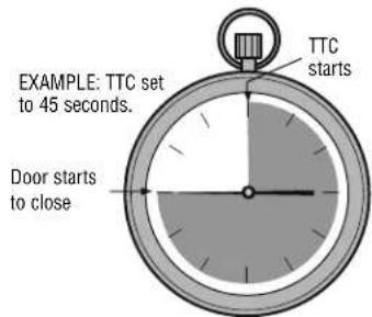
Timer-to-Close (TTC) with Pre-Warning: The TTC is an adjustable setting that can be set to automatically close the door after a specified period of time. Pre-Warning is a separate adjustable setting that will activate an auxiliary device for a specified period of time before the door starts to close (Figure 2).
FIGURE 2: TIMER-TO-CLOSE (TTC) WITH PRE-WARNING

TCP (TRAFFIC CONTROL MODE WITH PRE-WARNING) MODE 1
This mode is intended to control auxiliary devices connected to relays R1, R2, and R3 with optional flashing for relay R1. It also incorporates an adjustable Timer-to-Close (TTC) plus a separately adjustable Pre-Warning. The relays can be used with or without the timers programmed. This mode has similar functionality to the RDGRNCARD used with Logic 3 operators. This mode would be used in lieu of previous modification 90-T1, 90-515774, or RDGRNCARD functionality (light box not included).
1 Disconnect power to the operator.
TCP MODE 1 DIP SWITCH SETTINGS
2 Turn all the DIP switches on the TLS1CARD to the OFF position.

3 Connect the auxiliary device(s) to the input and output terminals on the TLS1CARD as described below.
Outputs:
- Connect a red light to the R1 terminals on the TLS1CARD. This will signal when the door is at any position other than the fully open, fully closed or at a programmed mid-stop. With a timer enabled, this relay is also the Pre-Warning signal when at fully open or at open mid-stop.
- Connect a green light to the R2 terminals on the TLS1CARD. This will signal that the door is fully open or at the open mid-stop position.
- Connect an audio/visual signalling device to the R3 terminals on the TLS1CARD. This will signal that the door is closing.
Inputs:
- If the application warrants the use of Timer Secure mode at some times and Timer modes at other times, set the operator selector dial to TS and make a connection to the T/TS input. The input should have a latched contact, such as a 2-position maintained keyswitch to switch between TS and T.
- If the application requires the ability to turn off the flash feature, connect a selector switch to the FD/SIS input terminals for a flasher defeat. The input device should have a latched contact, such as a 2-position maintained keyswitch. A jumper wire can also be used to disable the flash function.
| Fully Open (OLS) | Timer Stage 1 (OLS & OMS Only) | Timer Stage 2 (Pre-Warning) (OLS & OMS Only) | Closing | Fully Closed (CLS) | Opening Undefined Stopped Position (USP) | Open Mid-Stop (OMS) | Reversing from Obstruction | ||
| R1 LED | OFF | OFF | ON or Flash | ON or Flash | OFF | ON or Flash | ON | OFF | ON or Flash |
| R2 LED | ON | ON | OFF | OFF | OFF | OFF | OFF | ON | OFF |
| R3 LED | OFF | OFF | OFF | ON | OFF | OFF | OFF | OFF | OFF |
NOTES:
- Relay LEDs R1, R2, and R3 on the TLS1CARD will turn ON at the same time as relays R1, R2, and R3.
- During timer stages 1 and 2 the relays shown are only ON/OFF when the door is positioned as shown in parenthesis. The selector dial on the operator would be set to T, TS, or FSTS.

After configurations and connections have been made for your card mode proceed to Installation page 10.
TCP (TRAFFIC CONTROL MODE WITH PRE-WARNING) MODE 2
This mode is intended as a special input to open the door without activating the TImer-to-Close (TTC) while any other open signal will activate the TTC with Pre-Warning. It provides dry contact control based on the position/movement of the door and the TTC status. The relays can be used with or without the timers programmed. An open signal from the standard push button or radio input would not re-enable the timer if the special input to open has been enabled. This mode would be used in lieu of previous modification 90-T2.
1 Disconnect power to the operator.
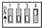
TCP MODE 2 DIP SWITCH SETTINGS
2 Turn DIP switch 4 on the TLS1CARD to the ON position. All other DIP switches should remain OFF.
3 Connect the auxiliary device(s) to the input and output terminals on the TLS1CARD as described below.
Outputs:
- Connect a red light to the R1 terminals on the TLS1CARD. This will signal the door is about to close.
- Connect a green light to the R2 terminals on the TLS1CARD. This will signal that the door is fully open.
- Connect an audio/visual signalling device to the R3 terminals on the TLS1CARD. This will signal that the door has been opened by the special input to open (SIO) and the timer is not enabled.
Inputs:
- Connect a push button, keyswitch, etc. to the SIO input terminals. This will open the door without enabling the TTC.
- If the application warrants the use of Timer Secure mode at some times and Timer modes at other times, set the operator selector dial to TS and make a connection to the T/TS input. The input should have a latched contact, such as a 2-position maintained keyswitch to switch between TS and T.
| Fully Open (OLS) | Timer Stage 1 (OLS Only) | Timer Stage 2 (Pre-Warning) (OLS, OMS, & USP Only) | Closing | Fully Closed (CLS) | Opening Undefined Stopped Position (USP) | Open Mid-Stop (OMS) | Reversing from Obstruction | ||
| R1 LED | OFF | OFF | ON | OFF | OFF | OFF | OFF | OFF | OFF |
| R2 LED | ON | ON | OFF | OFF | OFF | OFF | OFF | OFF | OFF |
| R3 LED | ON* | OFF | OFF | OFF | OFF | ON* | ON* | ON* | OFF |
NOTES:
- Relay LEDs R1, R2, and R3 on the TLS1CARD will turn ON at the same time as relays R1, R2, and R3.
- * R3 turns ON as soon as SIO is enabled and remains ON until closing begins.

After configurations and connections have been made for your card mode proceed to Installation page 10.
TCP (TRAFFIC CONTROL MODE WITH PRE-WARNING) MODE 3
This mode is intended to control auxiliary devices connected to relays R1, R2, and R3. It provides dry contact control based on the position/movement of the door and the Timer-to-Close (TTC) status. It also incorporates an adjustable TTC plus a separately adjustable Pre-Warning. The relays can be used with or without the timers programmed. This mode would be used in lieu of previous modification 90-T4.
1 Disconnect power to the operator.
TCP MODE 3 DIP SWITCH SETTINGS
2 Turn DIP switch 3 on the TLS1CARD to the ON position. All other DIP switches should remain OFF.

3 Connect the auxiliary device(s) to the input and output terminals on the TLS1CARD as described below.
Outputs:
- Connect a red light to the R1 terminals on the TLS1CARD. This will signal the door is about to close.
- Connect a green light to the R2 terminals on the TLS1CARD. This will signal that the door is fully open or at the open mid-stop position.
- Connect an audio/visual signalling device to the R3 terminals on the TLS1CARD. This will signal that the door is in motion.
Inputs:
- If the application warrants the use of Timer Secure mode at some times and Timer modes at other times, set the operator selector dial to TS and make a connection to the T/TS input. The input should have a latched contact, such as a 2-position maintained keyswitch to switch between TS and T.
| Fully Open (OLS) | Timer Stage 1 (OLS & OMS Only) | Timer Stage 2 (Pre-Warning) (OLS, OMS, & USP Only) | Closing | Fully Closed (CLS) | Opening Undefined Stopped Position (USP) | Open Mid-Stop (OMS) | Reversing from Obstruction | ||
| R1 LED | OFF | OFF | ON | OFF | OFF | OFF | OFF | OFF | OFF |
| R2 LED | ON | ON | OFF | OFF | OFF | OFF | OFF | ON | OFF |
| R3 LED | OFF | OFF | OFF | ON | OFF | ON | OFF | OFF | ON |
NOTES:
- Relay LEDs R1, R2, and R3 on the TLS1CARD will turn ON at the same time as relays R1, R2, and R3.
- During timer stages 1 and 2 the relays shown are only ON/OFF when the door is positioned as shown in parenthesis. The selector dial on the operator would be set to T, TS, or FSTS.

After configurations and connections have been made for your card mode proceed to Installation page 10.
TCP (TRAFFIC CONTROL MODE WITH PRE-WARNING) MODE 4
This mode is intended to control auxiliary devices connected to relays R1 and R2, with optional flashing for relay R1. It also incorporates an adjustable Timer-to-Close (TTC) plus a separately adjustable Pre-Warning. The relays can be used with or without the timers programmed. This mode would be used in lieu of previous modification 90-RGLFCIR or 90-HDFLASH2.
1 Disconnect power to the operator.
TCP MODE 4 DIP SWITCH SETTINGS
2 Turn DIP switch 3 and 4 on the TLS1CARD to the ON position. DIP switches 1 and 2 should remain OFF.

3 Connect the auxiliary device(s) to the input and output terminals on the TLS1CARD as described below.
Outputs:
- Connect a red light to the R1 terminals on the TLS1CARD. This will signal the door is about to close or is closing.
- Connect a green light to the R2 terminals on the TLS1CARD. This will signal that the door is fully open.
Inputs:
- If the application warrants the use of Timer Secure mode at some times and Timer modes at other times, set the operator selector dial to TS and make a connection to the T/TS input. The input should have a latched contact, such as a 2-position maintained keyswitch to switch between TS and T.
- If the application requires the ability to turn off the flash feature, connect a selector switch to the FD/SIS input terminals for a flasher defeat. The input device should have a latched contact, such as a 2-position maintained keyswitch. A jumper wire can also be used to disable the flash function.
| Fully Open (OLS) | Timer Stage 1 (OLS Only) | Timer Stage 2 (Pre-Warning) (OLS, OMS, & USP Only) | Closing | Fully Closed (CLS) | Opening Undefined Stopped Position (USP) | Open Mid-Stop (OMS) | Reversing from Obstruction | ||
| R1 LED | OFF | OFF | ON or Flash | ON or Flash | OFF | OFF | OFF | OFF | OFF |
| R2 LED | ON | ON | OFF | OFF | OFF | OFF | OFF | OFF | OFF |
| R3 LED | OFF | OFF | OFF | OFF | OFF | OFF | OFF | OFF | OFF |
NOTES:
- Relay LEDs R1, R2, and R3 on the TLS1CARD will turn ON at the same time as relays R1, R2, and R3.
- During timer stages 1 and 2 the relays shown are only ON/OFF when the door is positioned as shown in parenthesis. The selector dial on the operator would be set to T, TS, or FSTS.

After configurations and connections have been made for your card mode proceed to Installation page 10.
TCP (TRAFFIC CONTROL MODE WITH PRE-WARNING) MODE 5
Similar to Mode 2, this mode is intended as a special input to open the door without activating the Timer-to-Close (TTC) while any other open signal will activate the TTC with Pre-Warning. It provides dry contact control based on the position/movement of the door and the TTC status. The relays can be used with or without the timers programmed. An open signal from the standard push button or a radio input would not re-enable the timer if the special input to open has been enabled. This mode would be used in lieu of previous modification 90-T3.
1 Disconnect power to the operator.
TCP MODE 5 DIP SWITCH SETTINGS
2 Turn DIP switch 2 on the TLS1CARD to the ON position. All other DIP switches should remain OFF.

3 Connect the auxiliary device(s) to the input and output terminals on the TLS1CARD as described below.
Outputs:
- Connect a red light to the R1 terminals on the TLS1CARD. This will signal the door is not fully open or not fully closed.
- Connect a green light to the R2 terminals on the TLS1CARD. This will signal that the door is fully open.
- Connect an audio/signalling device to the R3 terminals on the TLS1CARD. This will signal that the door has been opened by the special input to open (SIO) and the timer is not enabled.
Inputs:
- Connect a push button, selector switch, loop detector, etc. to the SIO input terminals. This will open the door without enabling the TTC.
- If the application warrants the use of Timer Secure mode at some times and Timer modes at other times, set the operator selector dial to TS and make a connection to the T/TS input. The input should have a latched contact, such as a 2-position maintained keyswitch to switch between TS and T.
| Fully Open (OLS) | Timer Stage 1 (OLS Only) | Timer Stage 2 (Pre-Warning) (OLS Only) | Closing | Fully Closed (CLS) | Opening Undefined Stopped Position (USP) | Open Mid-Stop (OMS) | Reversing from Obstruction | ||
| R1 LED | OFF | OFF | ON | ON | OFF | ON | ON | ON | ON |
| R2 LED | ON | ON | OFF | OFF | OFF | OFF | OFF | OFF | OFF |
| R3 LED | ON* | OFF | OFF | OFF | OFF | ON* | ON* | ON* | OFF |
NOTES:
- Relay LEDs R1, R2, and R3 on the TLS1CARD will turn ON at the same time as relays R1, R2, and R3.
- * R3 turns ON as soon as SIO is enabled and remains ON until closing begins.

After configurations and connections have been made for your card mode proceed to Installation page 10.
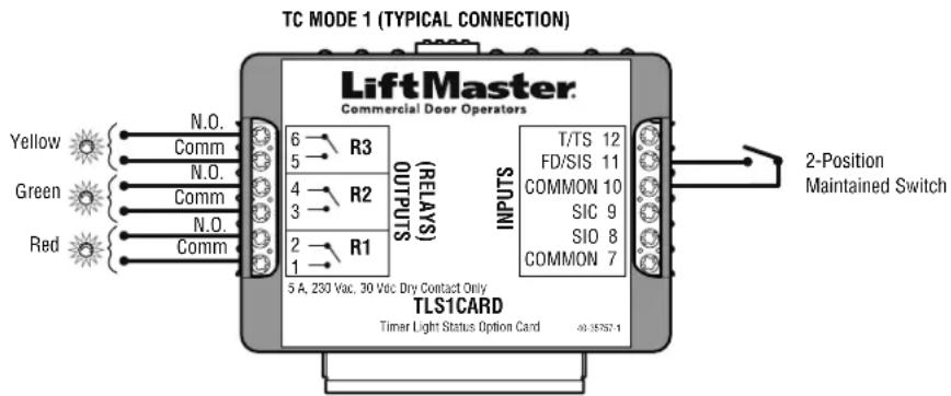
TC MODE 1
TC (TRAFFIC CONTROL MODE WITHOUT PRE-WARNING) MODE 1
This mode is intended to control devices connected to relays R1, R2, and R3 with optional flashing for relay R1. Relays R1, R2, and R3 can be used with or without the Timer-to-Close (TTC) programmed. This mode would be used in lieu of previous modification 90-L3FLASH.
1 Disconnect power to the operator.
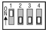
TC MODE 1 DIP SWITCH SETTINGS
2 Turn DIP switch 1 on the TLS1CARD to the ON position. All other DIP switches should remain OFF.
3 Connect the auxiliary device(s) to the input and output terminals on the TLS1CARD as described below.
Outputs:
- Connect a red light to the R1 terminals on the TLS1CARD. This will signal the door is in motion.
- Connect a green light to the R2 terminals on the TLS1CARD. This will signal that the door is at fully open or at the open mid-stop.
- Connect a yellow light to the R3 terminals on the TLS1CARD. This will signal that the door is not in motion or not fully closed.
Inputs:
- If the application requires the ability to turn off the flash feature, connect a selector switch to the FD/SIS input terminals for a flasher defeat. The input device should have a latched contact, such as a 2-position maintained keyswitch. A jumper wire can also be used to disable the flash function.
| Fully Open (OLS) | Timer Stage 1 (OLS & OMS Only) | Timer Stage 2 (Pre-Warning) | Closing | Fully Closed (CLS) | Opening Undefined Stopped Position (USP) | Open Mid-Stop (OMS) | Reversing from Obstruction | |
| R1 LED | OFF | OFF | NA | ON or Flash | OFF | ON or Flash | OFF | ON or Flash |
| R2 LED | ON | ON | NA | OFF | OFF | OFF | OFF | OFF |
| R3 LED | ON | ON | NA | OFF | OFF | OFF | ON | OFF |
NOTE: Relay LEDs R1, R2, and R3 on the TLS1CARD will turn ON at the same time as relays R1, R2, and R3.
After configurations and connections have been made for your card mode proceed to Installation page 10.
SP (SPECIAL MODES) MODE 1
This mode allows a second set of external, track mounted limits to act as primary or backup for the operator's open, close, and safety limits. The position of these limits can be set either before or after the operator's limits. This mode would be used in lieu of previous modification 90-42104.
NOTE: It is not required that all three inputs have a switch connected to the TLS1CARD. Either the external close, external safety, external open, or all three may be used.
1 Disconnect power to the operator.
SP MODE 1 DIP SWITCH SETTINGS
2 Turn DIP switches 1, 3, and 4 on the TLS1CARD to the ON position. DIP switch 2 should remain OFF.

3 Connect the auxiliary device(s) to the input and output terminals on the TLS1CARD as described below.
Outputs:
- Connect a red light to the R1 terminals on the TLS1CARD. This will signal that the external close limit switch has been activated.
- Connect a green light to the R2 terminals on the TLS1CARD. This will signal that the external open limit switch has been activated.
- Connect a yellow light to the R3 terminals on the TLS1CARD. This will signal that the external safety limit switch has been activated.
Required Inputs:
- Connect external CLOSE limit switch common and normally open contacts to the COMMON (#10) and FD/SIS (#11) terminals on the TLS1CARD respectively.
- Connect external OPEN limit switch common and normally open contacts to the COMMON (#10) and T/TS (#12) terminals on the TLS1CARD respectively.
- Connect external SAFETY limit switch common and normally open contacts to the COMMON (#10) and SIC (#9) terminals on the TLS1CARD respectively.
| External Open Limit External Safety Limit External Close Limit | |||
| R1 LED | OFF | OFF | ON |
| R2 LED | ON | OFF | OFF |
| R3 LED | OFF | ON | OFF |
NOTE: Relay LEDs R1, R2, and R3 on the TLS1CARD will turn ON at the same time as relays R1, R2, and R3.

After configurations and connections have been made for your card mode proceed to Installation page 10.
INSTALLATION
INSTALL THE TLS1CARD
1 Remove the electrical box cover of the operator. NOTE: Your operator may look different than the operator shown.
2 Insert the TLS1CARD onto either option card receptacle on the logic board.
3 See the following page if a Timer-to-Close (TTC) is required.
4 Reconnect power to the operator.

| TLS1CARD ERROR CODES | ||
| Number of Blinks | Error Description | Solution |
| 1 | Board Communication Error | Ensure TLS1CARD is seated properly and power cycle the operator. |
| 2 | Improper Mode Setting | Refer to manual for proper selection. |
| 3 | DIP Switch Changed During Operation | Check mode and reset the operator board by moving the selector dial to PROG and back to desired mode. |
| 4 | Operator Mode Not Compatible with the TLS1CARD Mode | Refer to manual for proper mode selection for both the operator board and the TLS1CARD. |
PROGRAMMING
TIMER-TO-CLOSE (TTC)
FUNCTION
The TTC automatically closes the door after a preset time. All entrapment protection devices must be unobstructed.
BENEFIT
The TTC is recommended for applications where the door should close after a specified amount of time, like apartment buildings or fire stations.
REQUIREMENTS
The application MUST have at least one of the following LiftMaster Monitored Entrapment Protection (LMEP) devices installed: CPS-U, CPS-UN4, or a CPS-EI with a valid door sensing edge. Wiring type must be set to T, TS, or FSTS.
TO PROGRAM
1 Close the door.
2 Turn the selector dial to PROG.
3 Press and release the TTC button on the logic board.
4 Press and release the STOP button to clear the timer.
5 Press and release the OPEN button for every second the operator should wait before attempting to close the door.
6 Press and release the CLOSE button for every 15 seconds the operator should wait before closing the door.
7 Press and release the TTC button to complete programming. The OPEN/CLOSE Button LEDs will flash to confirm the timer setting. The OPEN LED will flash once for every second programmed and the CLOSE LED will flash once for every 15 seconds programmed.
8 Turn the selector dial to desired timer wiring (TS, T, or FSTS).
EXAMPLE: To close the door after 70 seconds, turn the selector dial to PROG. Press and release the TTC button. Press and release the STOP button. Press and release the CLOSE button 4 times for 60 seconds and press and release the OPEN button 10 times for 10 seconds. Press the TTC button to finish programming the Timer-to-Close. Turn the selector dial to desired timer wiring type (TS, T, or FSTS), or follow the steps to program the Pre-Warning (following page).

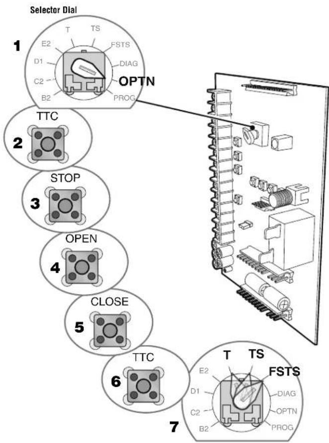
PRE-WARNING
NOTE: The TTC must be programmed prior to this step.
1 Turn the selector dial to OPTN.
2 Press and release the TTC button on the logic board.
3 Press and release the STOP button to clear the Pre-Warning setting.
4 Press and release the OPEN button for every second of Pre-Warning.
5 Press and release the CLOSE button for every 15 seconds of Pre-Warning.
6 Press and release the TTC button to complete programming. The OPEN/CLOSE button LEDs will flash to confirm the timer setting. The OPEN LED will flash once for every second programmed and the CLOSE LED will flash once for every 15 seconds programmed.
7 Turn the selector dial to desired timer wiring (TS, T, or FSTS). EXAMPLE: To close the door in 55 seconds and have 17 seconds of Pre-Warning:
Turn the selector dial to PROG. Press and release the TTC button. Press and release the STOP button. Press and release the CLOSE button 3 times for 45 seconds then press and release the OPEN button 10 times for 10 additional seconds. Press and release TTC button to finish programming the TTC. Turn the selector dial to OPTN. Press and release the TTC button. Press and release the STOP button. Press and release the CLOSE button once for 15 seconds then press and release the OPEN button twice for 2 additional seconds (total Pre-Warning equals 17 seconds). Press and release the TTC button to finish programming the Pre-Warning. Turn the selector dial to desired timer wiring type (TS, T or FSTS).
NOTE: It is not recommended to set the Pre-Warning to more than 30 seconds.
TIMER-TO-CLOSE (TTC) WITH PRE-WARNING


- Commercial Door Operators
- TLS1CARD
- TIMER LIGHT STATUS OPTION CARD
- WARNING WARN
- WARNING WARNING
- APPLICATION
- INTRODUCTION
- TIMER FUNCTIONS
- TCP (TRAFFIC CONTROL MODE WITH PRE-WARNING) MODE 1
- Outputs:
- Inputs:
- NOTES:
- TCP (TRAFFIC CONTROL MODE WITH PRE-WARNING) MODE 2
- TCP (TRAFFIC CONTROL MODE WITH PRE-WARNING) MODE 3
- TCP (TRAFFIC CONTROL MODE WITH PRE-WARNING) MODE 4
- TCP (TRAFFIC CONTROL MODE WITH PRE-WARNING) MODE 5
- TC MODE 1
- TC (TRAFFIC CONTROL MODE WITHOUT PRE-WARNING) MODE 1
- SP (SPECIAL MODES) MODE 1
- Required Inputs:
- INSTALLATION
- INSTALL THE TLS1CARD
- PROGRAMMING
- TIMER-TO-CLOSE (TTC)
- FUNCTION
- BENEFIT
- REQUIREMENTS
- TO PROGRAM
- PRE-WARNING
Brand : LiftMaster
Model : TLS1CARD
Category : Door automation