
DCS-3010 - Surveillance Camera D-LINK - Free user manual and instructions
Find the device manual for free DCS-3010 D-LINK in PDF.


| Product Type | Surveillance Camera |
| Brand | D-Link |
| Model | DCS-3010 |
| Image Sensor | 1/4" CMOS |
| Resolution | 640 x 480 (VGA) |
| Lens Type | Fixed, f=2.4 mm, F2.0 |
| Night Vision | Up to 5 m with IR LEDs |
| Video Compression | MJPEG |
| Audio | Built-in microphone |
| Connectivity | 10/100 Ethernet, Wi-Fi 802.11b/g |
| Power Supply | 5V DC, 2.5A (via adapter) |
| Power Consumption | 5.5 W max |
| Dimensions | 65 x 65 x 110 mm |
| Weight | 120 g (without stand) |
| Mounting | Desktop, wall, ceiling |
| Pan/Tilt | No (fixed) |
| Motion Detection | Yes, configurable |
| Alarm I/O | 1 input, 1 output |
| Storage | microSD card (not included), NAS |
| Operating Temperature | 0°C to 40°C |
| Humidity | 20% to 80% non-condensing |
| Certifications | CE, FCC |
| Maintenance | Clean lens with soft dry cloth |
| Repairability | Consult authorized service center |
Frequently Asked Questions - DCS-3010 D-LINK
User questions about DCS-3010 D-LINK
0 question about this device. Answer the ones you know or ask your own.
Ask a new question about this device
Download the instructions for your Surveillance Camera in PDF format for free! Find your manual DCS-3010 - D-LINK and take your electronic device back in hand. On this page are published all the documents necessary for the use of your device. DCS-3010 by D-LINK.
USER MANUAL DCS-3010 D-LINK
User Manual
HD PoE Fixed Network Camera
DCS-3010
Preface
D-Link reserves the right to revise this publication and to make changes in the content hereof without obligation to notify any person or organization of such revisions or changes.
Manual Revisions
| Revision Date Description | |
| 1.1 January 11, 2013 DCS-3010 R | Revision A1 with firmware version 1.10 |
Trademarks
D-Link and the D-Link logo are trademarks or registered trademarks of D-Link Corporation or its subsidiaries in the United States or other countries. All other company or product names mentioned herein are trademarks or registered trademarks of their respective companies.
Copyright © 2013 by D-Link Corporation.
All rights reserved. This publication may not be reproduced, in whole or in part, without prior expressed written permission from D-Link Corporation.
Table of Contents
Product Overview 4
Package Contents 4
System Requirements 5
Introduction 6
Features 7
Hardware Overview 8
Front Panel 8
Rear Panel 9
Side Panel 10
Side Panel 10
Button Panel 11
Installation 12
Hardware Installation 12
Configuration with Wizard 13
Viewing Camera via Web Browser 18
D-ViewCam Setup Wizard 20
Configuration 22
Live Video 22
Client Setup 26
Setup 27
Basic Setup 27
Advanced Setup 28
System Overview 29
Video 30
Video Settings 30
Image Settings 33
Audio Settings 35
Network 36
IP Settings 36
Port and Access Name Settings 39
Dynamic DNS 42
HTTPS 43
Access List 45
Advanced Settings 47
Event Management ....51
Motion Detection 51
Tamper Detection 52
Event Settings 53
Recording 60
Recording Settings 60
Local Storage 62
PTZ Control 63
Digital PTZ 63
System 64
User Settings 64
Device Settings 65
Time and Date 66
Maintenance 67
Parameter List 69
Logs 70
Appendix A - Technical Specifications .... 71
Technical Specifications 71
Package Contents
DCS-3010 HD PoE Fixed Network Camera
Mounting Bracket
User Manual and Software on CD-ROM


Power Adapter, CAT5 Ethernet Cable, Install Guide, Accessory wrench and lens ring fixture
If any of the above items are missing, please contact your reseller.
System Requirements
- Operating System: Microsoft Windows 2000, XP, Vista, 7 ■ Memory: At least 256MB of memory (512MB recommended)
- Web Browser: Internet Explorer 7 or higher, Firefox, Chrome, Safari
- VGA card resolution: SVGA or XGA (1024x768 or above)
- CPU: 1.7GHz or above (2.8GHz plus processor with 512MB memory and a 32MB video card is required for multiple camera viewing and recording in IP surveillance program) ■ An available Ethernet connection
Introduction
The DCS-3010 is an HD, full frame rate network camera with H.264 compression. It connects to a network to provide high-quality live video over the Internet. With vivid video quality and superb high resolution, it can provide the most detail of the video, which is useful for identifying any suspected object. The DCS-3010 provides multiple streaming and flexible viewing window settings for different surveillance purposes, either for regular recording or mobile viewing. The built-in SD card slot can record important events on an SD card as a local backup, and it is very easy to retrieve.
The included D-Link D-ViewCam™ is sophisticated software that allows users to manage up to 32 network cameras, set e-mail alert notifications, create recording schedules, and use motion detection to record directly to a hard drive. D-ViewCam™ also allows users to upload a floor plan to create a realistic layout of the premises where cameras are located, further simplifying the management process.
Features
HD Surveillance
The DCS-3010 provides HD industrial standard 16:9 widescreen video for IP surveillance. With the fixed lens, it is a high-performance, high-quality network camera. To utilize the advantage of high resolution, the "viewing window" design provides users with flexible settings to monitor multiple ROIs (Regions of Interest) with a single camera. The "ePTZ" can also simulate wide-area surveillance by digital zoom and pan/tilt control.
Flexible Connectivity
The DCS-3010 incorporates Power over Ethernet (PoE), allowing it to be easily installed in a variety of locations without the need for supplemental power cabling.
Advanced Web User Interface
The DCS-3010 features D-Link's latest-generation graphical user interface. This freshly designed web interface features a clean, compact, and professional home screen that dramatically increases usability. Menu navigation is simplified thanks to a tree view that logically groups functions, helping users to quickly find what they need. Likewise, intuitive graphic icons reduce the amount of text and clutter within the browser window. New users will appreciate the convenient contextual help, which offers an easy way to find assistance with camera management tasks.
3GPP Mobile Surveillance
Support for 3GPP Mobile Surveillance allows users to view a live video feed from a 3GPP-compatible Internet-ready mobile device. This extends monitoring capability, allowing users to check the camera's video feed while on the go without a computer.
Hardware Overview Front Panel

Rear Panel

Side Panel
Micro SD Card Slot
Local Micro SD card for storing
recorded images and video

Side Panel

Button Panel
DC-Iris Connector
Connector for DC auto iris lens

Hardware Installation
Basic Connection (without PoE)
Connect the camera to your switch or router via Ethernet cable.
Connect the supplied power cable from the camera to a power outlet.

Connection Using a PoE Switch
If using a PoE switch or router, connect the network camera via Ethernet cable.
PoE will transmit both power and data over a single cable.

Note: Once power has been established, the LED will turn red. When the device has obtained an IP address and is accessible, the LED will turn green.
Configuration with Wizard
Insert the DCS-3010 CD into your computer's CD-ROM drive to begin the installation. If the Autorun function on your computer is disabled, or if the D-Link Launcher fails to start automatically, click Start > Run. Type D:\autorun.exe, where D: represents the drive letter of your CD-ROM drive.
Click Setup Wizard to begin the installation.
After clicking Setup Wizard, the following window will open.
Click Next to continue.

Installation
Click Yes to accept the License Agreement.
To start the installation process, click Next.
Note: The installation may take several minutes to finish.


Installation
Click Finish to complete the installation.

Click on the D-Link Setup Wizard SE icon that was created in your Windows Start menu.
Start > D-Link > Setup Wizard SE

Installation
The Setup Wizard will appear and display the MAC address and IP address of your camera(s). If you have a DHCP server on your network, a valid IP Address will be displayed. If your network does not use a DHCP server, the network camera's default static IP 192.168.0.20 will be displayed.
Click the Wizard button to continue.

Enter the Admin ID and password. When logging in for the first time, the default Admin ID is admin with the password left blank.
Click Next to proceed to the next page.

Installation
Select DHCP if your camera obtains an IP address automatically when it boots up. Select static IP if the camera will use the same IP address each time it is started.
Click Next to proceed to the next page.

Take a moment to confirm your settings and click Restart.

Viewing Camera via Web Browser
Click on the D-Link Setup Wizard SE icon that was created in your Windows Start menu.
Start > D-Link > Setup Wizard SE

Select the camera and click the button labeled "Link" to access the web configuration.
The Setup Wizard will automatically open your web browser to the IP address of the camera.

Installation
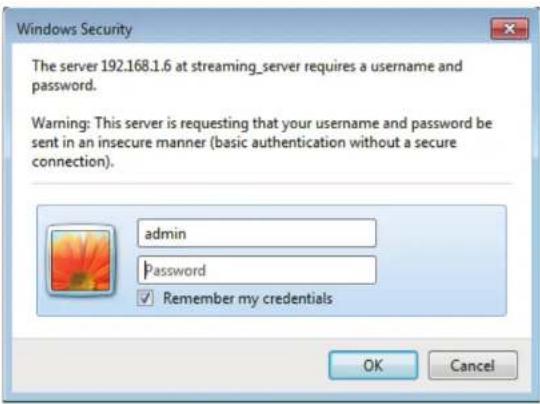
Enter admin as the default username and leave the password blank. Click OK to continue.
This section shows your camera's live video. You can select your video profile and view or operate the camera. For additional information about web configuration, please refer to the user manual included on the CD-ROM or the D-Link website.

D-ViewCam Setup Wizard
D-ViewCam software is included for the administrator to manage multiple D-Link IP cameras remotely. You may use the software to configure all the advanced settings for your cameras. D-ViewCam is a comprehensive management tool for IP surveillance.
Insert the CD-ROM into the CD-ROM drive. A menu screen will appear as shown below.

Follow the Installation Wizard to install D-ViewCam.

Installation
Click Finish to complete the installation.
To start D-ViewCam, select Start > All Programs > D-Link D-ViewCam > Main Console.
For more information about D-ViewCam, please refer to the documentation on the D-ViewCam CD-ROM.


Live Video
When you connect to the camera's web interface you will see the following page. This is the Live Video page which will allow you to view the camera's video feed and control basic camera functions using the icons on the screen. Please refer to the tables on the following pages for detailed information about the icons on this screen.

Configuration
D-Link D-Link Logo  Securicam Logo Securicam Logo | Click this logo to visit the D-Link website. The logos and website can be customized to fit your needs. For more information, please refer to User Customization on page 68. |
| Client Settings | Setup the stream transmission mode and saving options on the local computer. |
 Language Language | Select this option to adjust the language settings. |
 Setup Setup | Click on the setup icon on the main page to enter the camera setting pages. Note that only Administrators can access the setup page. To simplify the setting procedure, two types of user interfaces are available: Advanced Setup for professional users and Basic Setup for entry-level users. |
 Video Stream Video Stream | This camera supports multiple streams (stream 1 ~ 4) simultaneously. You may select one for live viewing. |
 Global View Global View | Click on this item to display the Global View window. The Global View window contains a full view image (the largest frame size of the captured video) and a floating frame (the viewing region of the current video stream). The floating frame allows users to control the e-PTZ function (Electronic Pan/Tilt/Zoom). For more information about e-PTZ operation, please refer to PTZ Control. For more information about how to set up the viewing region of the current video stream, please refer to Video settings on page 30. |

Configuration
 ePT Direction ePT Direction | This camera supports digital pan/tilt/zoom (ePTZ) control. Please refer to PTZ Control for details information.Home:Move the camera to the preset home position.Direction:Control the camera's pan or tilt directions (up/down/left/right). |
 Zoom Zoom | Zoom in/out to magnify or shrink the digital image.[IMAGE]Zoom in:Magnify image[IMAGE]Zoom out:Diminish image |
 Patrol Auto Pan Patrol Auto Pan | [IMAGE]Patrol:Patrol executes a pre-defined sequence of pan, tilt, zoom, and focus features Before selecting this, users must define at least two preset points.[IMAGE]Auto Pan:Auto Pan automatically scans an area horizontally. |
 Go Preset Go Preset | Select from the preset drop-down list to quickly move the camera to the desired preset position. |
 Speed Control Speed Control | Control Pan/Tilt/Zoom speedPan Speed ControlTilt Speed ControlZoom Speed Control |
Digital PTZ Control Panel
Configuration
| Camera Control | |
 Snapshot Snapshot | Click this button to capture and save still images. The captured images will be displayed in a pop-up window. Right-click the image and choose Save Picture As to save it in JPEG (*.jpg) or BMP (*.bmp) format. |
| [YXY0]Recording | Click this button to record video clips to your computer. When you exit the web browser, video recording stops accordingly. |
 Recording Folder Recording Folder | Specify a storage destination for the recorded video files. |
| [8608]Digital Zoom | Click and uncheck "Disable digital zoom" to enable the zoom operation. The navigation screen indicates the part of the image being magnified. To control the zoom level, drag the slider bar. To move to a different area you want to magnify, drag the navigation screen. |
| [7B37]Talk | Talk/Stop Talk: Click this button to talk to people around the Network Camera if there is an external speaker connected to the camera and you have a microphone connected to your computer. Press the icon again to stop talking or disable this function. |
 Microphone Level Microphone Level | Microphone Level: When the mute function is not active, move the slider bar to adjust the level of the microphone (internal/external) that is connected to your network camera. |
 Microphone Mute Microphone Mute | Microphone Mute/Un-mute: Click to turn off the microphone (internal/external) that is connected to your network camera. Press again to turn the microphone back on. |
| [GX60]Speaker Volumn | Speaker Volume - When the mute function is not active, move the slider bar to adjust the volume of the speakers that are connected to your network camera. |
| [3806]Speaker Mute | Speaker Mute/Un-mute: Click to mute the external speaker that is connected to the network camera. Press again to un-mute the speaker. |
| [450W]Full Screen | Click this button to switch to full screen mode. Press the "Esc" key to switch back to normal mode. |
   Zoom ratio Zoom ratio | Auto: The video zoom ratio will be changed automatically according to viewing window size.100%: Keep the video zoom ratio at 100%50%: Keep the video zoom ratio at 50%25%: Keep the video zoom ratio at 25% |
 Help Help | Click the Help button to learn the detailed information regarding camera setup and solve any problems you encounter. |
Client Setup
Clicking the Client Settings button will bring you to the following screen which allows you to configure the basic protocol options for your camera.
H.264/MPEG4 Media Options
Video and Audio can be viewed at the same time or separately.
Recording Options
Folder: Select the folder where you would like the recording file saved on your desktop computer.
File name prefix: Enter a file name prefix for the recording files. Add date and time suffix to file name: Select this checkbox if you would like the date and time to be added to the end of each filename.
Local Streaming Buffer Time
Enter the buffer time in milliseconds. The buffer will cause a slight delay between live activity and the video of the live stream but may increase the quality of video.

Setup
The DCS-3010 includes basic and advanced setup screens. Both screens include a tree view with multiple setup options. This manual includes detailed explanations for all advanced setup screens.
Basic Setup
Click the setup button to enter the setup screen.
Click on the basic button to enter the setup screen.
Please click the [+] next to each folder to view the options.
Basic setup includes the following options:
System Overview
Audio and Video
- Video Settings, Audio Settings
Network
- IP Settings
Event Management
- Motion Detection, Tamper Detection
PTZ Control
- Digital PTZ
System
- User Settings, Device Settings, Time and Date, Maintenance

Advanced Setup
Click the setup button to enter the setup screen.

Click on the advanced button to enter the setup screen.

Please click the [+] next to each folder to view the options.
Advanced setup includes the following options:
System Overview
Audio and Video
- Video Settings, Image Settings, Audio Settings
Network
- IP Settings, Port & Access Name Settings, Dynamic DNS, HTTPS, Access List, Advanced Settings
Event Management
- Motion Detection, Tamper Detection, Event Settings Recording
- Recording Settings, Local Storage
PTZ Control
- Digital PTZ
System
- User Settings, Device Settings, Time and Date, Maintenance, Parameter List, Logs

System Overview
The system overview page contains a summary of the camera's current settings. For more information about adjusting these settings, please consult the subsequent instructions found in this manual.

Video
Video Settings
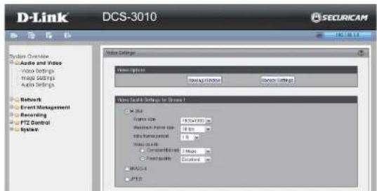
This page allows you to set up 4 video streams to be displayed on a computer, mobile device, or storage system. Each stream has independent options for proper compression type, frame size, frame rate to optimize the bandwidth utilization and video quality.
Video Options
Viewing Window: The camera supports multiple streams with frame size ranging from 176x144 to 1280x800. Click Viewing Window to open the viewing region setting page. On this page, you can set the Region of Interest (ROI) and the Output Frame Size for stream 1\~3. Please follow the steps below to set up a stream:
- Select a stream whose viewing region you would like to set.
- Select a Region of Interest from the drop-down list, the floating frame will resize accordingly. If you want to set up a customized viewing region, you can also resize and drag the floating frame to a desired position with your mouse.
- Choose a proper Output Frame Size from the drop-down list according to the size of your monitoring device.
Note: All the items in the "Output Frame Size" should not be greater than the "Region of Interest" (current maximum resolution).
The definition of multiple streams:
Stream 1-3: Users can define the "Region of Interest" (viewing region) and the "Output Frame Rate" (size of the live view window).
Stream 4: This is global view stream which captures the full view of the video. Users can also define the "Output Frame Rate" (size of the live view window).

Configuration
Once finished with the setting in the Viewing Window, click Save to enable the settings and click Close to exit the window. The selected Output Frame Size will immediately be applied to the Frame size of video stream. You can then go back to the Live Video to test the new settings.
Sensor Setting: Click Sensor Setting to open the Sensor Setting page. On this page, you can set the maximum exposure time, exposure level, and AGC (Auto Gain Control) setting. You can configure two sets of sensor setting: one for normal situations(Profile 1), the other for special situations, such as day/night/schedule mode(Profile 2).
Exposure
- Maximum Exposure Time: Select a proper maximum exposure time according to the light source of the surroundings. Shorter exposure times result in less light reaching the sensor. The exposure times are selectable for the following durations: 1/5, 1/15, 1/30, 1/60, 1/120, 1/240, 1/480.
- Exposure level: You can manually set the Exposure level which ranges from 1 to 8 (dark to bright).
- Max. Gain (Auto Gain Control): You can manually set the AGC level (2x, 4x, 8x, 16x, 32x). The higher the value, the brighter the image will be.
- Enable BLC (Back Light Compensation): Enable this option when the object is too dark or too bright to recognize. It allows the camera to adjust to the best light conditions in any environment and automatically give the necessary light compensation.
You may click Preview to fine-tune the image, or click Restore to recall the original setting without incorporating the changes. When completed with the setting on this page, click Save to enable the setting and click Close to exit the page. If you want to configure another sensor setting for day/night/schedule mode, please click Profile 2 and follow the steps below to setup:
- Click Enable this profile.
- Select the applied mode: Day mode, Night mode, or schedule mode. Please manually enter a range of time if you choose Schedule mode.
- Configure Exposure setting Configure Image setting in the third column.
- Click Save to enable the setting and click Close to exit the page.

![Profile 2 Live video (12P-A9) 2017/05/15 11:18 General Settings Enable this profile This profile is applied to Day mode Night mode Schedule mode From: 18:00 to 06:00 [Drawing]](/content/2026/06/1401392/images/92f5ac85083027fbea95cd5cfd74b97bf7da19d4e55b4978578bd104cc69b51d.jpg)
Configuration
Video Quality Setting for Stream 1\~4
Compression Type: The compression level affects the amount of bandwidth and storage required. Lower compression uses more bandwidth and storage but delivers better image quality. Of the three options, H.264 consumes much less network bandwidth compared to MPEG4 and JPEG.
Frame Size: Select proper frame size for different viewing devices, bigger frame size requires more bandwidth and storage usage. For smaller viewers, such as mobile phones, a smaller frame size and lower frame rate is recommended. There are 7 options you can select: 320x200, 640x400, 1280x800, if there is no viewing window applied. (176x144 for mobile phone, 1280x720).
Frame Rate: This option affects the smoothness of the video. Select higher frame rate for smoother video quality but it requires more storage usage. 10 options for selection: customize, 1, 2, 3, 5, 8, 10, 15, 20, 25, 30 fps (30 fps is recommended real-time video on a computer monitor. 5 fps is ideal for mobile viewers.)
Intra Frame Period: Determines the frequency and I frame is planted. The shorter the duration, the more likely you will get better video quality, but at the cost of higher network bandwidth consumption. Select the intra frame period from the following durations: 1/4 second, 1/2 second, 1 second, 2 seconds, 3 seconds and 4 seconds.
Video Quality: This setting limits the maximum refresh frame rate.
- Constant bit rate: To set a fixed bandwidth regardless of the video quality, select Constant bit rate and the desired bandwidth from 20 Kbps to 8 Mbps.
- Fixed quality: To optimize the bandwidth utilization and video quality. The video quality can be adjusted to the following setting: Medium, Standard, Good, Detailed and Excellent.
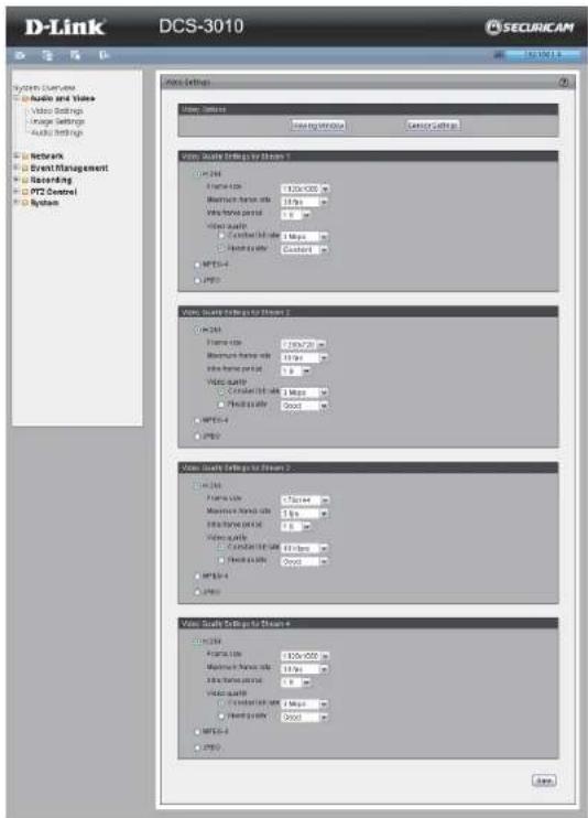
Image Settings
This page allows you to tune the white balance, brightness, saturation, contrast, and sharpness settings for the video.
Color: Select either a Color or B/W (black and white, monochrome) video display.
Power Line Frequency: Select either 50 or 60 Hz depending on your region.
Iris mode: fixed, indoor, outdoor
Video Orientation: Flip will vertically rotate the video. Mirror will horizontally rotate the video. You may select both options if camera is being installed upside down.
White Balance: This adjusts the relative amount of red, green and blue primary colors in the image so that the neutral colors are reproduced correctly.
- Auto: The camera automatically adjusts the color temperature of the light in response to different light sources. The white balance setting defaults to Auto and works well in most situations.
- Fixed: Follow the steps below to manually set the white balance to compensate for the ambient lighting conditions
- Set the White balance to Auto and click Save.
- Place a sheet of white paper in front of the lens, then allow the camera to adjust the color temperature automatically.
- Select Fixed to confirm the setting while the white balance is being measured.

Configuration
- Click Save to enable the new setting.
Brightness: Adjust the image brightness level, which ranges from -5 to +5.
Saturation: Adjust the image saturation level, which ranges from -5 to +5.
Contrast: Adjust the image contrast level, which ranges from -5 to +5.
Sharpness: Adjust the image sharpness level, which ranges from -3 to +3.
Overlay Title and Time Stamp on Video: Select this option to place the video title and time on the video streams. (When the frame size is set to 176 x 144, only the time will be stamped on the video streams.)
Note:
- The "Sensor Settings" and "Image Settings" share the same Profile 2 settings.
Privacy Mask: In this page, you can block out certain sensitive zones for privacy concerns. To set up a Privacy Mask Window, follow the steps given below:
- Click New to add a window.
- The height and width of the window can be resized and drag-dropped the window.
- Enter a descriptive Window Name and click Save to apply changes.
- Select Enable privacy mask to facilitate this function.
None:
- Up to 5 privacy mask windows can be set up on the same screen.
- If you want to delete the privacy mask window, please click the 'x' at the upper right-hand corner of the window.
![Line Style TCP-ABD 301/05/20 15:13:40 General Settings Enable line profile This profile is applied by Sequence mode From 16:00 To 06:00 [Min] Presence Maximum exposure time 175.0 Capture level 3 Max pin 30 Enable OLC Preview Preview Image Background Saturation Contrast Disinjection Preview Preview S…](/content/2026/06/1401392/images/2e799b514ec518a7dcff96864e424c9318890dad5978bae00e40ebe8c04100bf.jpg)

Audio Settings
Mute: Select to mute audio.
Microphone input gain: It is necessary to find the optimum gain between -15dB to +15dB that transmits the best audio for listening.
Audio type: Advanced Audio Coding (AAC) is a wide band audio coding algorithm that exploits two primary coding strategies to dramatically reduce the amount of data needed to convey high-quality digital audio. Select a higher bit rate number for better audio quality.
AAC bit rate: Select an AAC bit rate from the drop-down list. Higher bit rate means higher audio quality but it takes more network bandwidth to transmit.
GSM-AMR: A standard adapted audio codec by the 3GPP video (3rd Generation Partnership Project). It is an Adaptive Multi Rate-Narrow Band (AMRNB) speech codec. Select a higher bit rate number for better audio quality.
GSM-AMR bit rate: Select the GSM-AMR bit rate from the drop-down list. Higher bit rate means higher audio quality but it takes more network bandwidth to transmit.
G711 bit rate: Select an G711 bit rate from the drop-down list. Higher bit rate means higher audio quality but it takes more network bandwidth to transmit.

Network IP Settings
IPv4
LAN: Select this option when the camera is deployed on a local area network (LAN) and is intended to be accessed by local computers. The default setting for the Network Type is LAN. Remember to click Save when you complete the Network setting.
- Get IP address automatically (DHCP): Select this option if you have a DHCP server running on your network and would like a dynamic IP address to be assigned to the camera automatically.
- Use fixed IP address: You may enter a static or fixed IP address for your camera.
IP Address: Enter an IP address.
Subnet Mask: The default value is "255.255.255.0." This helps to determine if the designated IP address is on the same subnet.
Default Router: This is the gateway used to forward frames to destinations in a different subnet. (Invalid router settings will cause transmission to fail if the destination is in a different subnet).
Primary DNS: The Primary Domain Name Server (DNS) that translates hostnames into IP addresses.
Secondary DNS: Secondary Domain Name Server (DNS) that backs up the Primary DNS.
Primary WINS Server: The primary WINS server that maintains the database of computer names and IP addresses.


Secondary WINS Server: The secondary WINS server that maintains the database of computer names and IP addresses.
- Enable UPnP Presentation: Select this option to enable UPnP presentation for the camera so that whenever a camera is presented to the LAN, shortcuts of connected cameras will be listed in My Network Places. You can click the shortcut to link to the web browser. Currently, UPnP is supported by Windows XP or later. Note that to utilize this feature, please make sure the UPnP component is installed on your computer.
- Enable UPnP Port Forwarding: To access the camera from the Internet, select this option to allow the camera to open ports on the router automatically so that video streams can be sent out from a LAN. To utilize this feature, make sure that your router supports UPnP and it is activated.
How does UPnP work?
UPnP networking technology provides automatic IP configuration and dynamic discovery of devices added to a network. Services and capabilities offered by networked devices, such as printing and file sharing, are available among each other without bothersome network configuration. In the case of Network Cameras, you will see Network Camera shortcuts at My Network Places.
PPPoE: Select this option to configure the camera to make it accessible from anywhere with an Internet connection. Note that to utilize this feature, it requires an account provided by your ISP.
Follow the steps below to acquire the camera's public IP address.
- Set up the camera on the LAN
- Go to Live View > Setup > Event management > Event settings > Server Settings (please refer to Server Settings to add a new e-mail or FTP server)
- Go to Setup > Event management > Event settings > Media Settings (please refer to Media Settings). Select System log so that you will receive the system log in TXT file format which contains the camera's public IP address in your e-mail or on the FTP server.


Configuration
- Go to Setup > Network > IP settings. Select PPPoE and enter the user name and password provided by your ISP. Click Save to enable the setting.
- The camera will reboot.
- Disconnect the power to the camera. Remove it from the LAN environment.

Port and Access Name Settings
HTTPS
By default, the HTTPS port is set to 443. It can also be assigned to another port number between 1025 and 65535.
Note: JPEG only transmits a series of JPEG images to the client. In order to utilize this audio feature, make sure the video mode is set to H.264 or MPEG-4 and the media option in "Client Settings" is set to Video and Audio.
FTP
The FTP server allows the user to save recorded video clips. You can utilize D-Link's IP Cam Wizard to upgrade the firmware via FTP server. By default, the FTP port is set to 21. It also can be assigned to another port number between 1025 and 65535.
HTTP port/Secondary HTTP port
They can also be assigned to another port number between 1025 and 65535. To access the Network Camera on the LAN, both the HTTP port and secondary HTTP port can be used to access the Network Camera. For example, when the HTTP port is set to 80 and the secondary HTTP port is set to 8080, you can login to the camera as shown in the example links below: Http://192.168.0.20 or Http://192.168.0.20:8080
Authentication: Depending on your network security requirements, the Network Camera provides three types of security settings for streaming via HTTP protocol: disable, basic, and digest. If basic authentication is selected, the password is sent in plain text format, but there can be potential risks of it being intercepted. If digest authentication is selected, user credentials are encrypted using MD5 algorithm, thus providing better protection against unauthorized access.

Configuration
Access name for stream 1 ~ 4: This Network Camera supports multiple streams simultaneously. The access name is used to differentiate the streaming source. When using Mozilla Firefox or Netscape to access the Network Camera and the video mode is set to JPEG, users will receive video comprised of continuous JPEG images. This technology, known as "server push", allows the Network Camera to feed live pictures to Mozilla Firefox and Netscape. Use the following HTTP URL command to request transmission of the streaming data.
For example: http://<ip>:<port>/<access name> For example, when the Access name for stream 3 is set to video3.mjpg:
- Launch Mozilla Firefox or Netscape.
- Type the above URL command in the address bar. Press Enter.
- The JPEG images will be displayed in your web browser.
NOTE:
- Microsoft® Internet Explorer does not support server push technology; therefore, using http://<ip>:<port>/<access name> will fail to access the Network Camera.
RTSP
Authentication: Depending on your network security requirements, the Network Camera provides three types of security settings for streaming via RTSP protocol: disable, basic, and digest. If basic authentication is selected, the password is sent in plain text format, but there can be potential risks of it being intercepted. If digest authentication is selected, user credentials are encrypted using MD5 algorithm, thus providing better protection against unauthorized access.

Access name for stream 1 ~ 4: This Network Camera supports multiple streams simultaneously. The access name is used to differentiate the streaming source. If you want to use an RTSP player to access the Network Camera, you have to set the video mode to H.264 / MPEG-4 and use the following RTSP URL command to request transmission of the streaming data.
RTSP port /
RTP port for video, audio/
RTCP port for video, audio
RTSP (Real-Time Streaming Protocol) controls the delivery of streaming media. By default, the port number is set to 554.
The RTP (Real-time Transport Protocol) is used to deliver video and audio data to the clients. By default, the RTP port for video is set to 5556 and the RTP port for audio is set to 5558.
The RTCP (Real-time Transport Control Protocol) allows the Network Camera to transmit the data by monitoring the Internet traffic volume. By default, the RTCP port for video is set to 5557 and the RTCP port for audio is set to 5559.
The ports can be changed to values between 1025 and 65535. The RTP port must be an even number and the RTCP port is the RTP port number plus one, and thus is always an odd number. When the RTP port changes, the RTCP port will change accordingly.
Multicast: Click the items to display the detailed configuration information. Select the Always multicast option to enable multicast for stream 1 \~ 4.
Unicast video transmission delivers a stream through point-to-point transmission; multicast, on the other hand, sends a stream to the multicast group address and allows multiple clients to acquire the stream at the same time by requesting a copy from the multicast group address. Therefore, enabling multicast can effectively save network bandwidth.
Multicast RTP video, audio port/
Multicast RTCP video, audio port
The ports can be changed to values between 1025 and 65535. The multicast RTP port must be an even number and the multicast RTCP port number is the multicast RTP port number plus one, and thus is always odd. When the multicast RTP port changes, the multicast RTCP port will change accordingly.
Multicast TTL [1\~255]: The multicast TTL (Time To Live) is the value that tells the router the range a packet can be forwarded.
Dynamic DNS
This section explains how to configure the dynamic domain name service for the camera. DDNS is a service that allows your camera, especially when assigned with a dynamic IP address, to have a fixed host and domain name.
Enable DDNS: Select this option to enable the DDNS setting.
Server Name: Select a DDNS server name from the provider drop-down list. With a Dynamic DNS account, the camera automatically updates your IP address. To enable DDNS, enter your host information. Click Next to continue.
Host Name: Enter the host name of the DDNS server.
Username: Enter your username or e-mail used to connect to the DDNS.
Password: Enter your password used to connect to the DDNS server. Status: Indicates the connection status, automatically determined by the system.

HTTPS
This section explains how to enable authentication and encrypted communication over SSL (Secure Socket Layer). It helps protect streaming data transmission over the Internet on a higher security level.
Enable HTTPS
Select this item to enable HTTPS communication, then select a connection option: "HTTP & HTTPS" or "HTTPS only". Note that you have to create and install a certificate first in the second column before clicking the Save button.
Create and Install Certificate Method
Before using HTTPS for communication with the camera, a certificate must be created first.
There are three ways to create and install a certificate:
Create Self-signed Certificate Automatically
- Select this option.
- In the first column, select Enable HTTPS secure connection, then select a connection option: "HTTP & HTTPS" or "HTTPS only".
- Click Save to generate a certificate.
- The Certificate Information will automatically be displayed in the third column. You can click Property to view detailed information about the certificate.
- Click Live Video to return to the main page. Change the address from "http://" to "https://" in the address bar and press Enter. Some Security Alert dialogs will pop up. Click OK or Yes to enable HTTPS.
Create Self-signed Certificate Manually
- Click Create to open the Create Certificate page, then click Save to generate the certificate.
- The Certificate Information will automatically be displayed in the third column as shown below. You can click Property to see detailed information about the certificate.

Configuration
Create Certificate Request and Install
Select this option to create a certificate from a certificate authority.
- Click Create to open the Create Certificate page, then click Save to generate the certificate.
- If you see the information bar, click OK and click on the Information bar at the top of the page to allow pop-up.
- The pop-up window shows an example of a certificate request.
- Look for a trusted certificate authority that issues digital certificates. Enroll the camera.
Wait for the certificate authority to issue a SSL certificate. Click Browse... to search for the issued certificate, then click Upload in the second column.
How do I cancel the HTTPS setting?
- Deselect Enable HTTPS secure connection in the first column and click Save. A warning dialog will pop up.
- Click OK to disable HTTPS.
- The webpage will redirect to a non-HTTPS page automatically.
If you want to create and install other certificates, please remove the existing one. To remove the signed certificate, deselect Enable HTTPS secure connection in the first column and click Save. Then click Remove to erase the certificate.

Access List
This section explains how to control access permissions by verifying the connecting client PC's IP address.
General Settings
Maximum number of concurrent streaming connection(s) limited to: Simultaneous live viewing for 1~10 clients (including stream 1 ~ stream 5). The default value is 10. If you modify the value and click Save, all current connections will be disconnected and automatically attempt to re-link (I.E. Explorer or Quick Time Player).
View Information: Click this button to display the connection status window showing a list of the current connections.
• IP address: Current connections to the camera. - Elapsed time: How much time the client has been at the webpage. - User ID: If the administrator has set a password for the webpage, the clients have to enter a user name and password to access the live video. The user name will be displayed in the User ID column. If the administrator allows client to link to the webpage without a user name and password, the User ID column will be empty.
There are some situations which allow clients access to the live video without a user name and password:
- The administrator did not set up a user password. For more information about how to set up a user password and manage user accounts, please refer to User settings.
- The administrator has set up a user password, but set RTSP Authentication to "disable". For more information about RTSP Authentication, please refer to RTSP Streaming.


Configuration
- Refresh: Click this button to refresh all current connections.
- Add to deny list: You can select entries from the Connection Status list and add them to the Deny List to deny access. Please note that the selected connections will only be disconnected temporarily and will automatically try to re-link again (IE Explore or Quick Time Player). If you want to enable the denied list, please select Enable access list filtering and click Save in the first column.
Disconnect: If you want to break off the current connections, please select them and click this button. Please note that those selected connections will only be disconnected temporarily and will automatically try to re-link again (IE Explore or Quick Time Player).
Enable Access List Filtering: Select this item and click Save if you want to enable the access list filtering function.
Filter Type
Select Allow or Deny as the filter type. If you choose Allow Type, only those clients whose IP addresses are on the Access List below can access the camera, and the others cannot access. On the contrary, if you choose Deny Type, those clients whose IP addresses are on the Access List below will not be allowed to access the camera, and the others can access.
Filter
Then you can add a rule to the following Access List. Please note that the IPv6 access list column will not be displayed unless you enable IPv6 on the Network page. For more information about IPv6 Setting, please refer to Enable IPv6 for detailed information.
There are three types of rules:
Single: This rule allows the user to add an IP address to the Allowed/Denied list.
Network: This rule allows the user to assign a network address and corresponding subnet mask to the Allow/Deny List.
Range: This rule allows the user to assign a range of IP addresses to the Allow/Deny List (This rule is only applied to IPv4).
Administrator IP address
Always allow the IP address to access this device: You can select this item and add the Administrator's IP address in this field to make sure the Administrator can always connect to the device.
Advanced Settings
SNMP configuration
This section explains how to use the SNMP on the network camera. The Simple Network Management Protocol is an application layer protocol that facilitates the exchange of management information between network devices. It helps network administrators to remotely manage network devices and find, solve network problems with ease.
The SNMP consists of the following three key components:
- Manager: Network-Management Station (NMS), a server which executes applications that monitor and control managed devices.
- Agent: A network-management software module on a managed device which transfers the status of managed devices to the NMS.
- Managed device: A network node on a managed network. For example: routers, switches, bridges, hubs, computer hosts, printers, IP telephones, network cameras, web server, and database.
Before configuring SNMP settings on this page, please enable your NMS first. Enable SNMPv1, SNMPv2c: Select this option and enter the names of Read/Write community and Read Only community according to your NMS setting. Enable SNMPv3: This option contains cryptographic security, a higher security level which allows you to set the Authentication password and the Encryption password.
• Security name: According to your NMS setting, choose Read/Write or Read Only and enter the community name. - Authentication type: Select MD5 or SHA as the authentication method. - Authentication password: Enter the password for authentication (at least 8 characters). - Encryption password: Enter a password for encryption (at least 8 characters).

Configuration
IEEE 802.1x
Enable this function if your network environment uses IEEE 802.1x which is a port-based network access control. The network devices, intermediary switch/access point/hub, and RADIUS server must support and enable 802.1x setting.
The 802.1x standard is designed to enhance the security of local area networks, which provides authentication to network devices (clients) attached to a network port (wired or wireless). If all certificates between client and server are verified, a point-to-point connection will be enabled. If authentication fails, access on that port will be prohibited. 802.1x utilizes an existing protocol, the Extensible Authentication Protocol (EAP), to facilitate communication.
Please follow the steps below to enable 802.1x setting:
- Before connecting the camera to the protected network with 802.1x, please apply a digital certificate from a Certificate Authority (ie. MIS of your company) which can be validated by a RADIUS server.
- Connect the camera to a PC or notebook outside of the protected LAN. Open the configuration page of the camera as shown below. Select EAP-PEAP or EAP-TLS as the EAP method. In the following blanks, enter your ID and password issued by the CA, then upload related certificate(s).
- When all settings are complete, move the camera to the protected LAN by connecting it to an 802.1x enabled switch. The devices will then start the authentication automatically.
QoS (Quality of Service)
Quality of Service refers to a resource reservation control mechanism, which guarantees a certain quality to different services on the network. Quality of service guarantees are important if the network capacity is insufficient, especially for real-time streaming multimedia applications. Quality can be defined as, for instance, a maintained level of bit rate, low latency, no packet dropping, etc.

Configuration
The following are the main benefits of a QoS-aware network:
The ability to prioritize traffic and guarantee a certain level of performance to the data flow.
The ability to control the amount of bandwidth each application may use, and thus provide higher reliability and stability on the network.
Requirements for QoS:
To utilize QoS in a network environment, the following requirements must be met:
- All network switches and routers in the network must include support for QoS.
- The network video devices used in the network must be QoS-enabled.
CoS
IEEE 802.1p defines a QoS model at OSI Layer 2 (Data Link Layer), which is called CoS, Class of Service. It adds a 3-bit value to the VLAN MAC header, which indicates prioritization from 0 to 7 (eight different classes of service are available). The priority is set up on the network switches, which then use different queuing disciplines to forward the packets.
Please follow the steps below to enable CoS settings:
- Click Enable CoS.
- Enter the VLAN ID of your switch (0 to 4095).
- Choose the priority for each application (0 to 7).
Note:
- The VLAN Switch (802.1p) is required. Web browsing may fail if the CoS setting is incorrect.
- Class of Service technologies do not guarantee a level of service in terms of bandwidth and delivery time. They only offer a "best-effort." Users can think of CoS as "coarsely-grained" traffic control and QoS as "finely-grained" traffic control.
- Though CoS is simple to manage, it lacks scalability and does not offer end-to-end guarantees since it is based on L2 protocol.

Configuration
QoS/DSCP
DSCP-ECN defines QoS at Layer 3 (Network Layer). The Differentiated Services (DiffServ) model is based on packet marking and router queuing disciplines. The marking is done by adding a field to the IP header, called the DSCP (Differentiated Services Code Point). This is a 6-bit field that provides 64 different class IDs. It gives an indication of how a given packet is to be forwarded, known as the Per Hop Behavior (PHB). The PHB describes a particular service level in terms of bandwidth, queuing theory, and dropping (discarding the packet) decisions. Routers at each network node classify packets according to their DSCP value and give them a particular forwarding treatment. For example, how much bandwidth should be reserved.
Quality of Service refers to a resource reservation control mechanism, which guarantees a certain quality to different services on the network. Quality of service guarantees are important if the network capacity is insufficient, especially for real-time streaming multimedia applications. Quality can be defined as, for instance, a maintained level of bit rate, low latency, no packet dropping, etc.
Event Management Motion Detection
Motion can be detected by measuring change in speed or vector of an object or objects in the field of view.
Enable Motion Detection: Select this option to turn on the motion detection feature.
Window Name: Create your own name for the monitored area/ window. It will show at the top of the motion window.
Sensitivity: Set the measurable difference between two sequential images that would indicate motion.
Percentage: Set the amount of motion in the window being monitored that is required to trigger a motion detected alert. If this is set to 100%, this means that motion must be detected within the whole window to trigger a snapshot.
Note: Setting a higher sensitivity and a lower percentage will make motion easier to be detected.
New: Click to add a new window. A maximum of three motion windows can be opened simultaneously. Use your mouse to drag the window frame to resize or the title bar to move. Clicking on the 'x' at the upper right corner of the window will close the window.
Save: Save the configured settings.
To enable motion detection, follow the steps below:
- Click New to add a new motion detection window.
- Enter a name in the Window Name field.
- Define the sensitivity to moving objects and the space ratio of all alerted pixels by moving the Sensitivity and Percentage slide bar.
- Click Save to apply the changes.
- Select Enable motion detection to activate motion detection.


Profile:
You can configure two sets of sensor settings: one for normal situations (Profile1), the other for special situations (Profile2), such as day/night/schedule mode.
Tamper Detection
With tamper detection, the camera is capable of detecting incidents such as redirection, blocking or de-focusing, or even spray paint.
To enable tamper detection, follow the steps given below:
- Select Enable camera tampering detection.
- Enter the tamper trigger duration (10 sec. ~ 10 min.). The tamper alarm will be triggered only when the tampering factor (the difference between current frame and pre-saved background) exceeds the trigger threshold.
Set up the event source as Camera Tampering Detection on Event Settings > Server Settings (how to send alarm message) / Media Settings (send what type of alarm message) / Event Settings. Please refer to Event settings for detailed information.

Event Settings
This section explains how to configure the camera to respond to particular situations (events). A typical application is that when motion is detected, the camera sends buffered images to an FTP server or e-mail address as notifications.
Server Settings
Click Add Server on the Event Settings page to open the Server Setting page. On this page, you can specify where notification messages are sent when a trigger is activated. A total of 5 server settings can be configured.
Server name: Enter a name for the server setting.
- Server Type: There are four choices of server types available: E-mail, FTP, HTTP, and Network storage. Select the item to display the detailed configuration options. You can configure either one or all of them.
E-mail: Select to send the media files via e-mail when a trigger is activated.
- Sender e-mail address: Enter the e-mail address of the sender.
- Recipient e-mail address: Enter the e-mail address of the recipient.
- Server address: Enter the domain name or IP address of the e-mail server.
- User name: Enter the user name of the e-mail account if necessary.
- Password: Enter the password of the e-mail account if necessary.
- Server port: The default mail server port is set to 25. You can also manually set another port.
If your SMTP server requires a secure connection (SSL), select This server requires a secure connection (SSL).
To verify if the e-mail settings are correctly configured, click Test. The result will be shown in a pop-up window. If successful, you will also receive an e-mail indicating the result.
Click Save to enable the settings, then click Close to exit the page.


Configuration
FTP: Select to send the media files to an FTP server when a trigger is activated.
- Server address: Enter the domain name or IP address of the FTP server.
- Server port: By default, the FTP server port is set to 21. It can also be assigned to another port number between 1025 and 65535.
- User name: Enter the login name of the FTP account.
- Password: Enter the password of the FTP account.
- FTP folder name: Enter the folder where the media file will be placed. If the folder name does not exist, the camera will create one on the FTP server.
- Passive mode: Most firewalls do not accept new connections initiated from external requests. If the FTP server supports passive mode, select this option to enable passive mode FTP and allow data transmission to pass through the firewall.
To verify if the FTP settings are correctly configured, click Test. The result will be shown in a pop-up window as shown below. If successful, you will also receive a test.txt file on the FTP server.
Click Save to enable the settings, then click Close to exit the page.
HTTP: Select to send the media files to an HTTP server when a trigger is activated.
- URL: Enter the URL of the HTTP server.
- User name: Enter the user name if necessary.
- Password: Enter the password if necessary.
To verify if the HTTP settings are correctly configured, click Test. The result will be shown in a pop-up window as below. If successful, you will receive a test.txt file on the HTTP server. Click Save to enable the settings then click Close to exit the page.
Network storage: Select to send the media files to a network storage location when a trigger is activated. Click Save to enable the setting, then click Close to exit the page. When completed, the new server settings will automatically be displayed on the Event Settings page.


Media Settings
Click Add Media to open the Media Settings page. On this page, you can specify the type of media that will be sent when a trigger is activated. A total of 5 media settings can be configured.
Media name: Enter a name for the media setting.
Media Type: There are three choices of media types available: Snapshot, Video Clip, and System log. Select the item to display the detailed configuration options. You can configure either one or all of them.

Snapshot: Select to send snapshots when a trigger is activated.
Source: Select to take snapshots from stream 1 \~ 4.
Send pre-event images: The camera has a buffer area. It temporarily holds data up to a certain limit. Enter a number to decide how many images to capture before a trigger is activated. Up to 7 images can be generated.
Send post-event images: Enter a number to decide how many images to capture after a trigger is activated. Up to 7 images can be generated.
File name prefix: Enter the text that will be appended to the front of the file name.
Add date and time suffix to the file name: Select this option to add a date/time suffix to the file name.
Click Save to enable the settings, then click Close to exit the page.
Configuration
Video clip: Select to send video clips when a trigger is activated.
Source: Select a source of video clip.
Pre-event recording: The camera has a buffer area. It temporarily holds data up to a certain limit. Enter a number to decide the duration of recording before a trigger is activated. Up to 9 seconds can be set.
Maximum duration: Specify the maximum recording duration in seconds. Up to 20 seconds can be set. For example, if pre-event recording is set to 5 seconds and the maximum duration is set to 10 seconds, the camera continues to record for another 4 seconds after a trigger is activated.
Maximum file size: Specify the maximum file size allowed.
File name prefix: Enter the text that will be appended to the front of the file name.
Click Save to enable the settings, then click Close to exit the page.
System log: Select to send a system log when a trigger is activated. Click Save to enable the settings, then click Close to exit the page. When completed, click Save to enable the settings and click Close to exit this page. The new media settings will appear on the Event Settings page.
![Media Settings Media name: media2 Media Type Snapshot Video clip Source: Stream 3 Pre-event recording: 5 seconds [0-9] Maximum duration: 5 seconds [1-20] Maximum time: 028:1500 seconds (60-400ms) File name profile: videos System Log Save Close](/content/2026/06/1401392/images/0afddc7772c7d70fe3984220c53a4ad7d9bafc31b6b0a646593496d6f67331bb.jpg)

Configuration
Event Settings
In the Event Settings column, click Add to open the Event Settings page. On this page, you can arrange three elements -- Trigger, Schedule, and Action to set an event. A total of 3 event settings can be configured.
Event name: Enter a name for the event.
Enable this event: Select to activate this event.
Priority: Set the priority for this event (High, Normal, or Low). The event with higher priority will be executed first
Detect next event after * seconds: Select the delay time before selecting the next event. It is being used for both events of motion detection and digital input trigger.

Configuration
Trigger
This is the cause or stimulus which defines when to trigger the camera. The trigger source can be configured to use the camera's built-in motion detection mechanism. There are several choices of trigger sources as shown below. Select the item to display the detailed configuration options. The input type that triggers the event.
Video motion detection: This option makes use of the built-in motion detection mechanism as a trigger source. To enable this function, you need to configure a Motion Detection Window first. For more information, please refer to Motion Detection for details.
Periodically: This option allows the camera to trigger periodically for every other defined minute. Up to 999 minutes are allowed.
System boot: This option triggers the camera when the power to the camera is disconnected.
Recording notify: This option allows the camera to trigger when the recording disk is full or when recording starts to rewrite older data.
Camera tampering detection: This option allows the camera to trigger when the camera detects that it is being tampered with. To enable this function, you need to configure the Tamper detection option first. Please refer to Tamper detection for detailed information.
Event Schedule
Specify the period for the event
- Select the days of the week.
- Select the recording schedule in 24-hr time format.

Configuration
Action
Define the actions to be performed by the camera when a trigger is activated.
To set an event with recorded video or snapshots, it is necessary to configure the server and media setting so that the camera will know what action to take (i.e. the server to send the media files to) when a trigger is activated.
- Add Server: same as Server Settings
- Add Media: same as Media Settings
Recording Recording Settings
Click Add to open the recording setting page. In this page, you can define the recording source, recording schedule, and recording capacity. A total of 2 recording settings can be configured.
Recording name: Enter a name for the recording setting
Enable this recording: Select this option to enable video recording
Priority: Select the relative importance of this recording setting (High, Normal, and Low).
Source: Select the recording source (stream 1 \~ 4).
Trigger: Select a trigger source.
Schedule: The server will start to record files on the network storage (NAS).
Recording Schedule: Specify the recording duration.
- Select the days of the week.
- Select the recording start and end times in 24-hr time format.
Destination: You can select the network storage or local SD card that was set up for the recorded video files.
Capacity: You can choose either the entire free space available or limit the reserved space. The recording size limit must be larger than the reserved amount for cyclic recording.
File name prefix: Enter the text that will be appended to the front of the file name.

![Recording Recording name: Irish Enable this recording Priority: Normal Source: Stream 1 Trigger Schedule Networktail Recording Schedule Sun Mon Tue Wed Thu Fri Sat Time Always From 08:00 Fri 18:00 [mm] Destination: Survey4 Capacity Entire free space Reserved space: 100 Mbytes File name profile Enabl…](/content/2026/06/1401392/images/7cda1878e39a29d71116d86af69f01c2795e293ccbc88c6b2c637dd9465b23de.jpg)
Configuration
Enable cyclic recording: If you select this item, when the maximum capacity is reached, the oldest file will be overwritten by the latest one. The reserved amount is reserved for cyclic recording to prevent malfunction. This value must be larger than 15 Mbytes.
If you want to enable recording notification, please click Application to set up. Please refer to Trigger > Recording notify for detailed information.
When completed, select Enable this recording. Click Save to enable the setting and click Close to exit this page. When the system begins recording, it will send the recorded files to the Network Storage.
The new recording name will appear in the drop-down list on the recording page.
To remove a recording setting from the list, select a recording name from the drop-down list and click Delete.
Local Storage
This section explains how to manage the local storage on the Network Camera. Here you can view SD card status, search for recorded files to playback, download, etc.
SD Card Management
SD card status: This column shows the status and reserved space of your SD card. Please remember to format the SD card when using for the first time.
SD card control: Enable cyclic storage: Check this item if you want to enable cyclic recording. When the maximum capacity is reached, the oldest file will be overwritten by the latest one.
Enable automatic disk cleanup: Check this item and enter the number of days you wish to retain a file. For example, if you enter "7 days", the recorded files will be stored on the SD card for 7 days. Click Save to enable your settings.
Searching and Viewing the Records
This column allows the user to set up search criteria for recorded data. If you do not select any criteria and click Search button, all recorded data will be listed in the Search Results column.
File attributes: Select one or more items as your search criteria.
Trigger time: Manually enter the time range you want to search. Click Search and the recorded data corresponding to the search criteria will be listed in Search Results Window.
Search Results
This area will show the search results. There are four columns: Trigger time, Media type, Trigger type, and Locked. Click up and down arrow to sort the search results in either direction.

PTZ Control Digital PTZ
You can set a total of 20 preset positions and select preset positions for the camera to patrol.
Please follow the steps below to preset a position:
- Adjust the shooting area to the desired position using the buttons on the right side of the window.
- Enter a name for the preset position, which allows for up to forty characters. Click Add to enable the Setting. The preset positions will be displayed under the Preset Location list on the left-hand side.
- To add additional preset positions, please repeat steps 1~2.
- To remove a preset position from the list, select it from the drop-down list and click Delete.
- The preset positions will also displayed on the main page. Please refer to the illustration on the next page.
- Click Save to enable the setting. The Preset Positions will also be displayed on the Live Video. Select one from the drop-down list and the camera will move to the selected preset position.
Patrol Setting
You can select some preset positions for the camera to patrol.
Please follow the steps below to set up a patrol schedule:
- Click a preset location on the list and click Select.
- The selected preset location will be displayed on the Source list.
- Set the Dwelling time for the preset location during auto patrol. You can also manually enter a value in the blank and click Update.
- Repeat step 1 and 3 to select additional preset locations.
- If you want to delete a selected location, select it from the Source list and click Remove.
- Select a location and click Up or Down to rearrange the patrol order.
- Click Save to enable the setting.

System User Settings
This section explains how to enable password protection and create multiple accounts.
Admin Password Setup:
The administrator account name is "admin", which is permanent and cannot be deleted. The default of password is empty.
Add user account: Add a new user account.
Username: Enter a username for the new account.
Password: Enter a password for the new account.
Privilege: Select the access rights for the new user.
Manage user: Manage the accounts for existing users.
Authentication: The access rights for existing users.

Device Settings
Turn off the LED indicator: Select this option to turn off the LED next to the lens. This will prevent anyone from observing the operation of the network camera.
Camera Name: Create a unique name for your camera.

Time and Date
Automatically or manually configure, update, and maintain the internal system clock for your camera.
Current Server Time: Displays camera's current time.
Time Zone: Select your time zone from the drop-down menu.
Daylight saving time: At some area, the clocks are adjusted one hour forward during the warmer months in a year. Set the start and end date and time of Daylight saving time according to your location.
Automatic Time Configuration: Enable this feature to obtain time configuration automatically from NTP server.
NTP Server: Network Time Protocol (NTP) synchronizes the network camera with an Internet time server. Choose the one that is closest to your location. Update Interval: The time interval for updating the time information from NTP server.
Set the date and time manually: This option allows you to set the time and date manually.
Copy Your Computer's Time Setting: This will synchronize the time information from your PC.

Maintenance
This chapter explains how to restore the camera to factory default, upgrade firmware version, etc.
Reboot: This feature allows you to reboot the camera, which takes about one minute to complete. When completed, the live video page will be displayed in your browser. The following message will be displayed during the reboot process.
If the connection fails after rebooting, manually enter the IP address of the camera in the address field to resume the connection.
Restore to default: This feature allows you to restore the camera to factory default setting.
Export / Upload Files: This feature allows you to Export / Upload daylight saving time rules, custom language files, and setting backup files. Export daylight saving time configuration file: Click to set the start and end time of DST.
Follow the steps below to export:
- In the Export files column, click Export to export the daylight saving time configuration file from the camera.
- A file download dialog will pop up as shown below. Click Open to review the XML file or click Save to store the file for editing.
- Open the file with Microsoft® Notepad and locate your time zone. Set the start and end time of DST.
- When completed, save the file
Upload daylight saving time rule: Click Browse... and specify the XML file to upload.

Configuration
Upload custom language file: Click Browse... and specify your own custom language file to upload.
Export setting backup file: Click to export all parameters for the device and user-defined scripts.
Upload setting backup file: Click Browse... to upload a setting backup file. Please note that the model and firmware version of the device should be the same as the setting backup file. If you have set up a fixed IP or other special settings for your device, it is not suggested to upload a settings backup file.
Firmware upgrade: This feature allows you to upgrade the firmware of your camera. It takes a few minutes to complete the process.
Note: Do not power off the camera during the upgrade!
Follow the steps below to upgrade the firmware:
- Download the latest firmware file from the D-Link website. The file is in .pkg file format.
- Click Browse... and specify the firmware file.
- Click Upgrade. The camera starts to upgrade and will reboot automatically when the upgrade completes.
If the upgrade is successful, you will see "Reboot system now!! This connection will close". After that, re-access the camera.
Parameter List
The Parameters List page lists the entire system's parameters in alphabetical order. If you need technical assistance, please provide the information listed on this page.

Logs
This section explains how to configure the camera to send the system log to the remote server as backup.
Remote Log: You can configure the camera to send the system log file to a remote server as a log backup. Before utilizing this feature, it is suggested that a log-recording tool be first installed on the remote server to receive system log messages from the camera. Be sure to note the IP address of the remote server.
Follow the steps below to set up the remote log:
- In the IP address text box, enter the IP address of the remote server.
- In the port text box, enter the port number of the remote server.
- When completed, select Enable remote log and click Save to enable the setting.
Current Log: This column displays the system log in chronological order. The system log is stored in the camera's buffer area and will be overwritten when reaching a certain limit.
![Log Enable remote log IP address: port: 514 Save Current Log New 3.12.41.31 (cypugd 1.5.0 nodult) New 3.12.41.32 (vntublog). Ready to check tripd New 3.12.41.33 [EVENT MDR]. Starting events with support for EcTun New 3.12.41.34 [VnetS0] (endapid) unknown service New 3.12.41.35 [DRM Service]. Startin…](/content/2026/06/1401392/images/964aaf2253529e965fd2145a2966df702bc54a2c1b8a0f0b8f4a799a2261a4e4.jpg)
Technical Specifications
| Camera | Hardware Profile | 1/4" 1 Megapixel CMOS sensor256 Mbytes SDRAM32 Mbytes of flash memory4mm fixed lens | Aperture F1.5Angle of view56.9° (H)35.9° (V) |
| Image Features | Configurable image size, quality, frame rate, and bit rateTime stamp and text overlays3 configurable motion detection windows | 5 configurable privacy mask zonesConfigurable brightness, saturation, contrast, and sharpnessMin Illumination: 1 lux / F1.5 | |
| Video Compression | Simultaneous H.264/MPEG-4/MJPEG format compressionH.264/MPEG-4 multicast streaming | JPEG for still images | |
| Video Resolution | 16:9 - 1280 x 800, 1280 x 720, 800 x 450, 640 x 360, 480 x 270, 320 x 176, 176 x 144 up to 30 fps recording1 | 4:3 - 1024 x 768, 800 x 600, 640 x 480, 480 x 360, 320 x 240, 176 x 144 up to 30 fps recording1 | |
| Audio Features | GSM-AMR speech encoding, bit rate: 4.75 kbps to 12.2 kbpsG.711 audio encoding, bit rate: 8 kbps to 64 kbpsMPEG-4 AAC audio encoding, bit rate: 16 kbps to 128 kbps | ||
| Network | Network Protocols | IPv4TCP/IPUDPICMPDHCP clientNTP client (D-Link)DNS clientDDNS client (D-Link)SMTP clientFTP clientHTTP / HTTPS | Samba clientPPPoEUPnP port forwardingRTP / RTSP/ RTCPIP filteringQoSCoSMulticastIGMPONVIF compliant |
| Security | Administrator and user group protectionPassword authenticationHTTPS streaming | HTTP and RTSP digest encryptionRemote client access control |
Appendix A - Technical Specifications
| System Management | System Requirements for Web Interface | Browser: Internet Explorer, Firefox, Chrome | |
| Event Management | Motion detectionEvent notification and uploading of snapshots/video clips via e-mail or FTP | Supports multiple SMTP and FTP serversMultiple event notificationsMultiple recording methods for easy backup | |
| Remote Management | Take snapshots/video clips and save to local hard drive or NAS via web browserConfiguration interface accessible via web browser | ||
| Mobile Support | Windows 7/Vista/XP system, Pocket PC, or mobile phonemydlink mobile app for iOS and Android mobile devices | ||
| D-ViewCamTM System Requirements | Operating System: Microsoft Windows 7/Vista/XPWeb Browser: Internet Explorer 7 or higher | Protocol: Standard TCP/IP | |
| D-ViewCamTM Software Functions | Remote management/control of up to 32 camerasViewing of up to 32 cameras on one screenScheduled motion triggered, or manual recording optionsSupports all management functions in web interface | ||
| Physical | Weight | 165 g (0.34 lb) | |
| Power | 12V DC 1.25 A, 802.3af PoE | ||
| Power Consumption | 4.6W (12V DC), 6.6W (PoE). | ||
| Temperature | Operating: 0 to 40 °C (32 to 104 °F) | Storage: -20 to 70 °C (-4 to 158 °F) | |
| Humidity | Operating: 20% to 80% non-condensing | Storage: 5% to 95% non-condensing | |
| Certifications | CECE LVD | FCCC-Tick | |
| Dimensions |   | ||


- USER MANUAL
- HD POE FIXED NETWORK CAMERA
- PREFACE
- MANUAL REVISIONS
- TRADEMARKS
- TABLE OF CONTENTS
- PRODUCT OVERVIEW
- INSTALLATION
- CONFIGURATION
- APPENDIX A - TECHNICAL SPECIFICATIONS
- PACKAGE CONTENTS
- SYSTEM REQUIREMENTS
- INTRODUCTION
- FEATURES
- HD SURVEILLANCE
- FLEXIBLE CONNECTIVITY
- ADVANCED WEB USER INTERFACE
- GPP MOBILE SURVEILLANCE
- HARDWARE OVERVIEW FRONT PANEL
- REAR PANEL
- SIDE PANEL
- BUTTON PANEL
- HARDWARE INSTALLATION
- BASIC CONNECTION (WITHOUT POE)
- CONNECTION USING A POE SWITCH
- CONFIGURATION WITH WIZARD
- VIEWING CAMERA VIA WEB BROWSER
- D-VIEWCAM SETUP WIZARD
- LIVE VIDEO
- CLIENT SETUP
- H.264/MPEG4 MEDIA OPTIONS
- RECORDING OPTIONS
- LOCAL STREAMING BUFFER TIME
- SETUP
- BASIC SETUP
- SYSTEM OVERVIEW
- AUDIO AND VIDEO
- NETWORK
- EVENT MANAGEMENT
- PTZ CONTROL
- SYSTEM
- ADVANCED SETUP
- VIDEO
- VIDEO SETTINGS
- VIDEO OPTIONS
- EXPOSURE
- VIDEO QUALITY SETTING FOR STREAM
- IMAGE SETTINGS
- NOTE
- NONE
- AUDIO SETTINGS
- NETWORK IP SETTINGS
- IPV
- HOW DOES UPNP WORK
- PORT AND ACCESS NAME SETTINGS
- HTTPS
- FTP
- HTTP PORT/SECONDARY HTTP PORT
- RTSP
- RTSP PORT
- RTP PORT FOR VIDEO, AUDIO
- RTCP PORT FOR VIDEO, AUDIO
- MULTICAST RTP VIDEO, AUDIO PORT
- MULTICAST RTCP VIDEO, AUDIO PORT
- DYNAMIC DNS
- ENABLE HTTPS
- CREATE AND INSTALL CERTIFICATE METHOD
- CREATE SELF-SIGNED CERTIFICATE AUTOMATICALLY
- CREATE SELF-SIGNED CERTIFICATE MANUALLY
- CREATE CERTIFICATE REQUEST AND INSTALL
- HOW DO I CANCEL THE HTTPS SETTING
- ACCESS LIST
- GENERAL SETTINGS
- FILTER TYPE
- FILTER
- ADMINISTRATOR IP ADDRESS
- ADVANCED SETTINGS
- SNMP CONFIGURATION
- IEEE 802.1X
- QOS (QUALITY OF SERVICE)
- THE FOLLOWING ARE THE MAIN BENEFITS OF A QOS-AWARE NETWORK
- REQUIREMENTS FOR QOS
- COS
- QOS/DSCP
- EVENT MANAGEMENT MOTION DETECTION
- PROFILE
- TAMPER DETECTION
- TO ENABLE TAMPER DETECTION, FOLLOW THE STEPS GIVEN BELOW
- EVENT SETTINGS
- SERVER SETTINGS
- MEDIA SETTINGS
- TRIGGER
- EVENT SCHEDULE
- ACTION
- RECORDING RECORDING SETTINGS
- LOCAL STORAGE
- SD CARD MANAGEMENT
- SEARCHING AND VIEWING THE RECORDS
- SEARCH RESULTS
- PTZ CONTROL DIGITAL PTZ
- PATROL SETTING
- SYSTEM USER SETTINGS
- ADMIN PASSWORD SETUP
- DEVICE SETTINGS
- TIME AND DATE
- MAINTENANCE
- PARAMETER LIST
- LOGS
Brand : D-LINK
Model : DCS-3010
Category : Surveillance Camera