ProSample - Measuring equipment YSI - Free user manual and instructions
Find the device manual for free ProSample YSI in PDF.


| Product Type | Water Sampler / Water Quality Monitoring System |
| Dimensions | Approx. 30 x 20 x 15 cm |
| Weight | Approx. 2.5 kg (including batteries) |
| Power | 8 x AA alkaline batteries or rechargeable battery pack |
| Display | LCD with backlight |
| Memory | Stores up to 5000 data points |
| Communication | USB and Bluetooth for data transfer |
| Functions | Sample collection, temperature, pH, conductivity, dissolved oxygen measurement |
| Maintenance | Rinse with clean water after use; calibrate sensors per schedule |
| Safety | IP67 waterproof rating; shock-resistant casing |
| Spare Parts | Available from YSI authorized dealers |
| General | Portable, rugged design for field use; includes carrying case |
Frequently Asked Questions - ProSample YSI
User questions about ProSample YSI
0 question about this device. Answer the ones you know or ask your own.
Ask a new question about this device
Download the instructions for your Measuring equipment in PDF format for free! Find your manual ProSample - YSI and take your electronic device back in hand. On this page are published all the documents necessary for the use of your device. ProSample by YSI.
USER MANUAL ProSample YSI
natural_image
Exterior view of a smart water heater mounted on a concrete platform with stairs in the background (no signage or text visible)YSI ProSample
Instructions for portable automatic samplers
ProSample instrument safety information
Please read this entire manual before unpacking, setting up, or operating this equipment.
Pay attention to all precautionary statements. Failure to do so could result in serious injury to the operator or damage to the equipment. Make sure that the protection provided by this equipment is not impaired. Do not use or install this equipment in any manner other than that specified in this manual.
NOTICE: The manufacturer is not responsible for any damages due to misapplication or misuse of this product including, without limitation, direct, incidental and consequential damages, and disclaims such as damages to the full extent permitted under applicable law. The user is solely responsible to identify critical application risks and install appropriate mechanisms to protect processes during a possible equipment malfunction.
Precautionary symbols in the manual
NOTE: Information that requires special emphasis
NOTICE: Indicates a situation which, if not avoided, may cause damage to the instrument

WARNING: Indicates a potentially hazardous situation which could result in injury
Precautionary symbols on the instrument

Reference relevant section of this manual for operation and/or safety information

Appears on the outside of the peristaltic pump cover. This cover should not be open while the instrument is on, as the user can be seriously injured if they are exposed to moving parts in the peristaltic pump assembly.
This is an interactive document
Clicking on elements of the table of contents, website URLs, or references to certain sections will take you automatically to those locations within the document.
Table of contents
0. Safety information.... 2
1. Introduction ...... 6
1.1 Intended use and overview.... 6
1.1.1 Keypad overview....7
1.1.2 LED functionality....8
1.2 Package contents 8
1.3 Unpacking....9
1.4 Technical specifications.... 10
1.5 Dimensions ...... 11
2. Power options ...... 12
2.1 Battery.... 12
2.1.1 Battery life and capacity 12
2.1.2 Charging and installing the battery....12
2.1.3 Enabling sleep mode 14
2.2 External power options.... 16
2.2.1 Connect the battery to mains power 16
2.2.2 External battery....18
3. Installation 19
3.1 Choosing a sampling site.... 19
3.2 Suction hose connection, positioning, and length 20
3.3 Harness applications 22
4. Instrument setup and calibration 23
4.1 Installing the tubing.... 23
4.1.1 Peristaltic pump tube....23
4.1.2 Intermediate tube....24
4.2 Turning the ProSample on 25
4.3 Sample bottle installation....25
4.3.1 Remove the top of the housing....25
4.3.2 Prepare sample bottles and install....26
4.3.3 Reattach the top of the housing 27
4.4 Distributor arm installation.... 28
Contents
4.5 Configure key instrument settings.... 29
4.6 Water sensor calibration.... 31
4.7 Peristaltic pump volume calibration 33
4.7.1 Calibration containers ....33
4.7.2 Calibration procedure....33
4.7.3 Calibration check 34
4.7.4 After calibration and/or calibration check....34
5. Connecting analog, digital I/O, and SDI-12 devices 35
5.1 Flow signal cable wiring 35
5.1.1 Calibrating the analog signal....36
5.2 SDI-12 cable wiring 37
5.2.1 SDI-12 cable with flying leads....37
5.2.2 SDI-12 cable with EXO3 connector....37
5.3 Triggering a program.... 38
5.3.1 Analog input trigger 39
5.3.2 Digital input trigger....43
5.3.3 SDI-12 input trigger 44
6. Sampling program 49
6.1 Sampling scenario list and descriptions.... 49
6.2 Main menu tree 50
6.3 Program start options.... 52
6.4 Program end options.... 53
6.5 Program status 53
6.5.1 Status/stop 54
6.6 Time-paced....55
6.7 Flow digital....58
6.8 Flow analog 62
6.9 Event time.... 67
6.10 Event digital 71
6.11 Event analog 77
6.12 Variable time 82
6.13 Event batch sampling 87
Contents
7. Special program functions ...... 91
7.1 Programming OK....91
7.2 Serial samples 91
7.3 Bottle assignment 91
7.4 Program pause 92
7.5 QT-Automatic (Q=flow, T=time) 92
7.6 Combined event mode 92
7.7 Program linkage....93
7.8 Absolute start time 93
7.9 Bottle filling pause.... 94
8. Maintenance and cleaning.... 95
8.1 Factory reset 95
8.2 Draining bottom housing 95
8.3 Desiccant replacement....96
8.4 Peristaltic pump tube replacement 97
8.5 Cleaning 97
8.6 Changing fuses 98
8.7 Long-term storage....98
9. YSIConnect PC software 99
9.1 Connection.... 100
9.2 Memory....101
9.3 Programming....103
9.4 Display 104
9.5 Tools 104
9.6 Updating the firmware....105
10. Stored messages and errors....110
10.1 Status messages.... 110
10.2 Error messages 110
10.3 Log messages.... 111
11. Replacement parts and accessories....113
-
Warranty and liability....118
-
Technical support ....118
-
Service information ..... 118
1. Introduction
Thank you for purchasing a YSI portable automatic sampler. Samplers in the ProSample series are designed to collect field samples and provide temporary storage before they are analyzed in a laboratory.
1.1 Intended use and overview
The ProSample portable automatic samplers are designed for surface water, storm water, and wastewater applications. These samplers can be used in various scenarios, most described in this manual. If you have a question regarding using a sampler in your project, please contact YSI (ysi.com/contact-us) or an authorized YSI distributor.
The ProSample provides temporary storage for liquids of a specified volume to be analyzed.
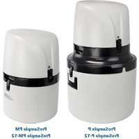
There are four samplers in the ProSample series. Content in this user manual applies to all ProSample models unless otherwise noted. ProSample models include:
• ProSample P: full-size portable sampler
• ProSample P-12: full-size portable sampler with SDI-12 connectivity
• ProSample PM: mini portable sampler
• ProSample PM-12: mini portable sampler with SDI-12 connectivity
Composite sampling can be completed with all ProSample models. In this type of sampling, a single container collects multiple samples, resulting in a mixture of all collected samples.
Discrete sampling can be completed with the ProSample P and ProSample P-12. In this type of sampling, samples are placed in different bottles. There are several bottle configurations available for discrete sampling.
All ProSample models have the following features:
- Robust PE, double-walled, insulated housing for temperature control
- Easy tube replacement for minimal downtime
- Spring-loaded roller bearings in the peristaltic pump provide long tubing life
- Highly accurate sample volume using two capacitive sensors for volume control
- Simple programming and calibration
- Long battery life
• IP-65 waterproof rating
• Non-volatile data memory for up to 5 years, so you never have to worry about losing your data if power is lost
1.1.1 Keypad overview

ProSample keypad
| Select the desired menu.Con rimation of entered values and selections.A con rmed selection is indicated with √ | Enter key |  |
| Move within the menu. Move to the next menu.Entry/change of values. | Arrow keys |  |
| Selection within the menu. Scrolling within the data memory or bottle memory. Entry/change of values. | Arrow keys |  |
| Return to higher menu level. The activity is cancelled. Back key |  | |
| Terminate sleep mode | Back key,Press for at least 5 seconds |  |
| Initialization (reset) display | Back key + Enter |   Press both keys at the same time Press both keys at the same time |
| Terminate sleep mode Back key |  Press for at least 5 sec. Press for at least 5 sec. | |
| RESET/reset to factory settings(NOTE: all settings and data will be deleted!) | Back key |  Keep pressed when turning on Keep pressed when turning on |

1.1.2 LED functionality
There is an LED on the front of each ProSample that functions as follows:
- OFF: Device power is off, battery is dead, or no program is running
• Solid Green: Program is running and there are no errors - Blinking Green: Program is running, but the battery is getting low
• Solid Red: An error has occurred. The display should be viewed for more information regarding the cause of the error - Blinking Red: Battery capacity is critically low
1.2 Package contents
Included with each ProSample:
- Battery
- USB cable
- Two peristaltic pump tubes
• ProSample Quick Start Guide (printed)
• 10 L PE container (only the ProSample PM and the ProSample PM-12) - 5-meter* suction hose with screw connection and sinker weight
*Up to a 30-meter suction hose can be used with any ProSample model.
Please note the following items are not included with any ProSample. These items must be purchased separately:
- Battery charger
- Flow signal cable
- Other accessories, such as strainers
- SDI-12 cable for the ProSample P-12 and ProSample PM-12
- Bottle sets and distributor arms for the ProSample P and ProSample P-12
Please see Section 11, Replacement parts and accessories, for more details and item numbers, including longer suction hose lengths. The ProSample User manual, the installation file for YSICnect, and the ProSample Ordering guide can be found at ysi.com/ProSample.
1.3 Unpacking
Carefully unpack the unit and accessories and inspect for shipping damage. Compare the received parts with the materials listed in the Package contents section. Notify YSI immediately of any damage or missing parts. Save all packing materials until satisfactory operation is confirmed.
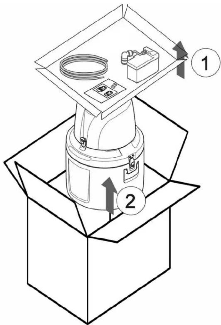
Removing the top tray (1) and the ProSample (2) from the packaging
1.4 Technical specifications
ProSample specifications
Power supply
| With integrated battery 12 V-7.2 Ah (DC) |
| With external power 12 V/50–60 Hz. |
| Rating 8 AT |
| Power consumption Peristaltic pump: approx. 70VA |
Environment
| Sample temperature 0 to 40 °C [32 to 104 °F] |
| Ambient temperature 0 to 50 °C [32 to 113 °F] |
| Suction height 6.5 m [20 ft], optional < 8 m [26 ft] |
Weight (without battery) ProSample PM ProSample P
| With integrated battery approx. 5 kg approx. 6.5 kg |
| With external power approx. 3.5 kg approx. 8.5 kg |
| Rating approx. 8.5 kg approx. 15 kg |
| Dimensions (H x D) in mm | ProSample PM ProSample P | |
| Top part | 400 x 333 | 500 x 377 |
| Bottle compartment | 400 x 310 | 500 x 415 |
| Complete | 400 x 605 | 500 x 740 |
| With lid opened (90°/110°) | 90° 400 x 710 110° 400 x 685 | 90° 500 x 843 110° 500 x 819 |
Certi cation
| CE, sampling per ISO 5667-2/3-10 |
NOTE: Technical specifications are subject to change without notice
1.5 Dimensions
NOTE: Unit of measurement is mm.
YSI ProSample P (Portable)


YSI ProSample PM (Portable Mini)


2. Power options
2.1 Battery
2.1.1 Battery life and capacity
The battery provided with the ProSample is a 12 V/7.5 Ah sealed lead-acid battery.
Battery life
| H-3401, power, and SDI connected 1 hour |
| Program running but idle, no samples collected 36 hours |
| No program running, no samples collected 4.5 days (108 hours) |
NOTE: A battery charger is not included with the purchase of a ProSample and must be purchased separately.
Battery chargers
YSI Item # Description Used with
| 630137 | Battery charger, IP-67 (waterproof) rated, for US customers, CEC compliant | All ProSample models |
| 630122 | Battery charger, IP-67 (waterproof) rated, for non-US customers, does not include international adapters | All ProSample models |
| 630144 | Battery charger, not IP-67 (waterproof) rated, for non-US customers, does not include international adapters | All ProSample models |
| 630153 International adapter kit 630122 and 630144 chargers | ||
2.1.2 Charging and installing the battery
Initial charge: The battery must be completely charged before first use.
This should take approximately 14 to 16 hours.
NOTICE: A total discharge of the battery can damage the battery. A protective mechanism is built-in, which automatically switches off the device when the voltage is too low (9V or less). However, when storing the battery long-term, regularly connect the battery to the charger to top off the charge, as this will ensure the battery does not completely discharge.
NOTE: Please include the battery if the ProSample is returned to YSI for service — see the Technical support section and the Service information section.
To charge, connect a ProSample battery charger to the battery. Once the red light on the power supply turns green, the battery is fully charged and can be installed in the ProSample unit.
NOTE: Three different battery chargers are available for the ProSample.
For a list of please see the Replacement parts and accessories section for available chargers.

natural_image
Simple line drawing of a battery connected to a power outlet via a cable (no text or symbols)Connection of the ProSample battery to the battery charger
Battery installation: The battery pack is not installed in the ProSample during shipment.
NOTICE: It is recommended to disconnect the battery from the instrument when transporting the ProSample.
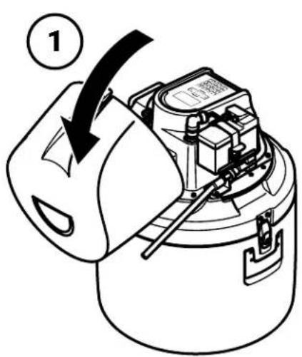
To install the battery:
-
Open the ProSample cover
-
Secure it with the strap
-
Insert the battery pack into the battery tray
-
Connect the battery plug to the battery
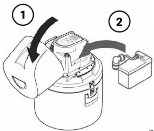
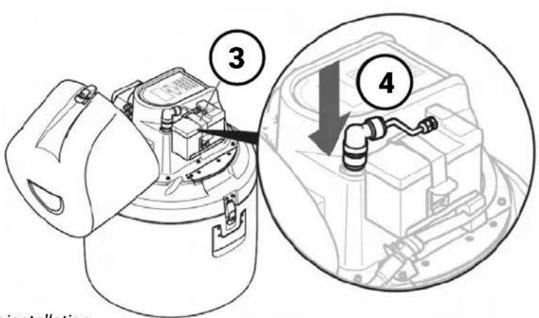
Battery installation
Subsequent battery charges
NOTE: When charging a new battery, it is recommended to use the steps in the Initial charge section.
The battery must always be installed in the ProSample when the sampler is in use.
The ProSample will shut off when the battery drops below 9V.
The battery can be periodically charged by removing it from the instrument and charging it with a ProSample battery charger whenever needed (see the Initial Charge section). This is the most common method of powering the instrument when no mains (AC) power source is located near the ProSample unit.
2.1.3 Enabling sleep mode
When the ProSample is powered on and running a program that waits for a signal from a connected device but does not collect samples, it is considered idle or in Standby mode. The ProSample requires approximately 100 mA while in Standby mode (i.e., approx. 2.5 Ah per day), meaning the 7.5 Ah battery would last less than four days.
Sleep mode can reduce energy consumption and prolong the battery life during deployments.
The polling interval, or the time between communication with a connected probe or device, can be increased in the Sleep mode menu. The ProSample wakes from Sleep mode to read the connected probe data, then goes back to sleep until the next polling interval is due. The default polling interval is five minutes. The greater the polling interval, the more time the ProSample spends in Sleep mode and the longer the battery life can be extended.
If a program is running, the sampler also wakes up to collect samples when the program conditions are met. An increased sampling interval can extend the battery life if running a Time-based program.

natural_image
Outdoor scene of a person operating an outdoor scientific equipment setup with a blue cylindrical device and open chamber, surrounded by gravel and trees (no visible text or symbols)


To enable sleep mode:
- From the Main Menu, select Setup.
- In the Settings menu, select Sleep Mode.
- To turn on Sleep Mode, select Active.
If sleep mode has been activated and the program will be started in 20 minutes at the earliest, the message "Attention device switches to sleep mode" is displayed for 30 seconds.
Thereafter, the display is switched off and only activated for 2 minutes.
- Highlight the Measurement Interval and press the Enter key.
- Adjust the polling interval, or how often the ProSample wakes to check the status of connected devices during Sleep Mode.
2.2 External power options
There are two options for external power connections to the ProSample:
- Connection to mains (AC) power
- Connection to a larger external battery
Both options will allow the ProSample to run for a longer period of time without recharging a battery, if the battery even needs to be recharged at all.
2.1.1 Connect the battery to mains power
Keeping the battery continuously connected to mains (AC) power is also possible. In this scenario, the battery is kept in the instrument, and an optional Y-cable (item # 0069810) is used to connect the battery to the battery charger and the instrument. This is the most common method of powering the instrument when a mains (AC) power source is located near the ProSample unit. Since the battery charger will typically be outdoors and/or exposed to water, an IP-67 battery charger is recommended (see Section 11, Replacement parts and accessories).
NOTE: The battery must be completely charged before first use. It is recommended to initially charge the battery by connecting it directly to the battery charger (i.e., the 'Y' cable is not used) – see the Initial charge section.
The Y-cable can be used once the battery is initially charged.
For continuous connection of the battery to AC power via the Y-cable:
- Open the ProSample cover
- Disconnect the battery from the instrument (see next page)
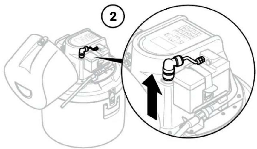
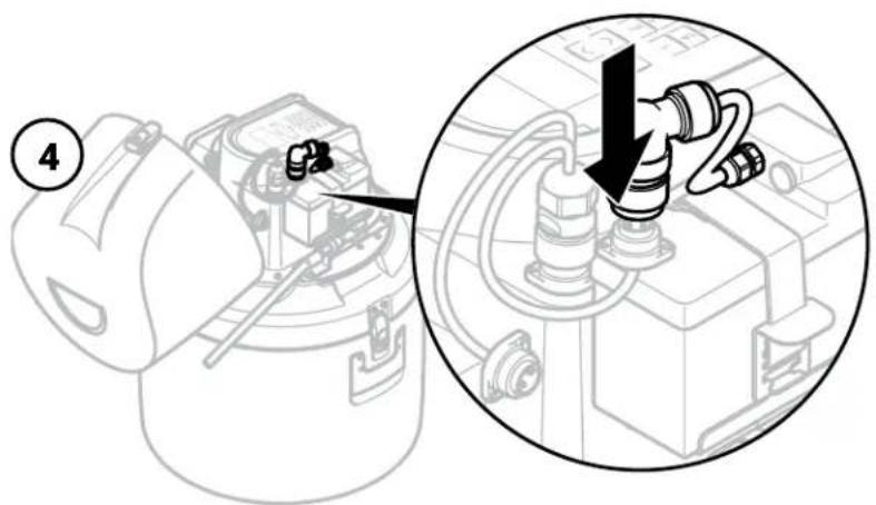
For continuous connection of the battery to AC power via the Y-cable, (continued):
- Connect the Y-cable to the instrument

- Connect the Y-cable to the battery
- Connect the Y-cable to the battery charger

2.2.2 External battery
It is possible to connect a larger-capacity battery to the ProSample for longer deployments than would be possible with the included 7.5 Ah battery, provided it supplies 12V to the system. For example, marine-grade batteries can be stored outside the ProSample housing and connected to the instrument via the Flying Lead Cable (Item #630155).
The ends of the flying lead cable are kept bare so that the user can attach any electrical connection options they desire for attachment to the external battery (e.g., alligator clips).
It is recommended that the larger battery and cable ends be stored inside a waterproof case to prevent water exposure. The external battery may be continuously recharged using a combination of solar panels and regulators. A solar power regulator must be installed when connecting to a solar panel to ensure that the battery does not become overcharged, as this can cause equipment to fail.
To connect the ProSample to an external battery:
- Connect the flying lead cable connector to the ProSample battery connector
- Connect the negative (black) lead to the negative terminal on the battery
- Connect the positive (red) lead to the positive terminal on the battery
NOTE: The flying lead cable has a built-in fuse to prevent power surges from reaching the ProSample. If the fuse blows, order Item #630119 (Fuse T 8A 5x20) as found in the Replacement parts and accessories section.
3. Installation
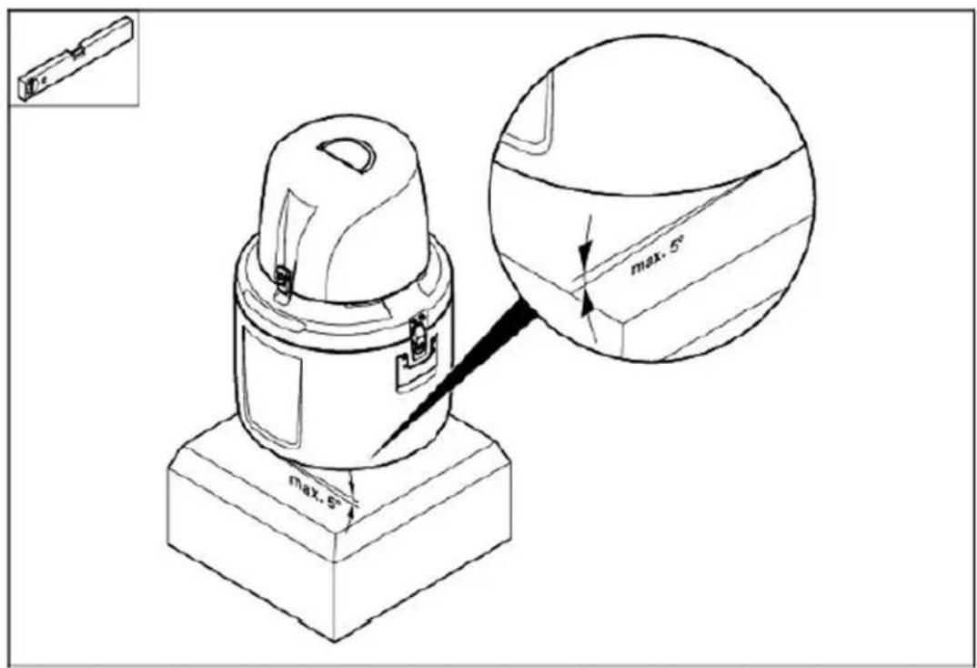
The ProSample unit must be placed on a steady, level surface.
YSI recommends carefully planning the installation location before drilling holes, cutting tubing, etc. Choose a sampling location where sample is well-mixed and avoid areas with high aeration and high velocity. Install the ProSample above high water lines or expected water level.
The ProSample should be installed where the sample temperature is between 0^ and 40^ . The sampler should not be exposed to explosive substances or an environment with an explosive atmosphere.

WARNING: If the unit is to be continuously connected to AC power, ensure the electrical supply is sufficiently protected against short circuits.
3.1 Choosing a sampling site
The ProSample should be installed on level ground with a maximum slope of five degrees. The best position can be determined using a level. The unit may be secured by tethering it to nearby structures.
3.2 Suction hose connection, positioning, and length
The suction hose transports water from the sampling site to the sampler. The correct positioning of the suction hose is another key consideration when installing a ProSample unit. One end of the suction hose connects to the intermediate tube, while the other end is placed in the environment where samples are collected.

Suction hose connection to the intermediate tube
NOTE: The ProSample intermediate tube and suction hose connectors are 34 inch-14BSPP. If not using a YSI suction hose (5, 10, and 20 meters available), ensure the suction hose being used has a 34 inch-14BSPP connection. A 34 inch-14BSPP female connection (Item # 630127) is available if the suction hose used does not have a 34 inch-14BSPP connection.
Upon delivery, the suction hose has a small zip-tied gasket. Place this gasket in the suction hose connector before connecting the suction hose to the intermediate tube. This gasket prevents air from getting in the line, thus ensuring accurate solution dispensing.
The suction hose cannot be longer than 30 meters.
In addition, it should be positioned so it is descending in elevation from the sampler to the sampling point. This also applies when the ProSample is tested or calibrated in a lab setting. Locations marked with a red 'X' on the figure on the next page are examples where this requirement is not satisfied. Placing the hose in a PVC pipe can help meet this requirement.
The hose should not be coiled, as this can allow water to collect in the excess hose and impede water travel. If the suction hose is longer than needed, remove the sinker weight at the end of the suction hose, cut the suction hose to the desired length, and then reinstall the sinker weight.
Strainers can be installed on the suction hose to help prevent large particles from clogging the line. To install a strainer, the metal end of the suction hose can be removed or cut off to push the strainer through the hose. See Section 11, Replacement parts and accessories for available strainers for the YSI ProSample.


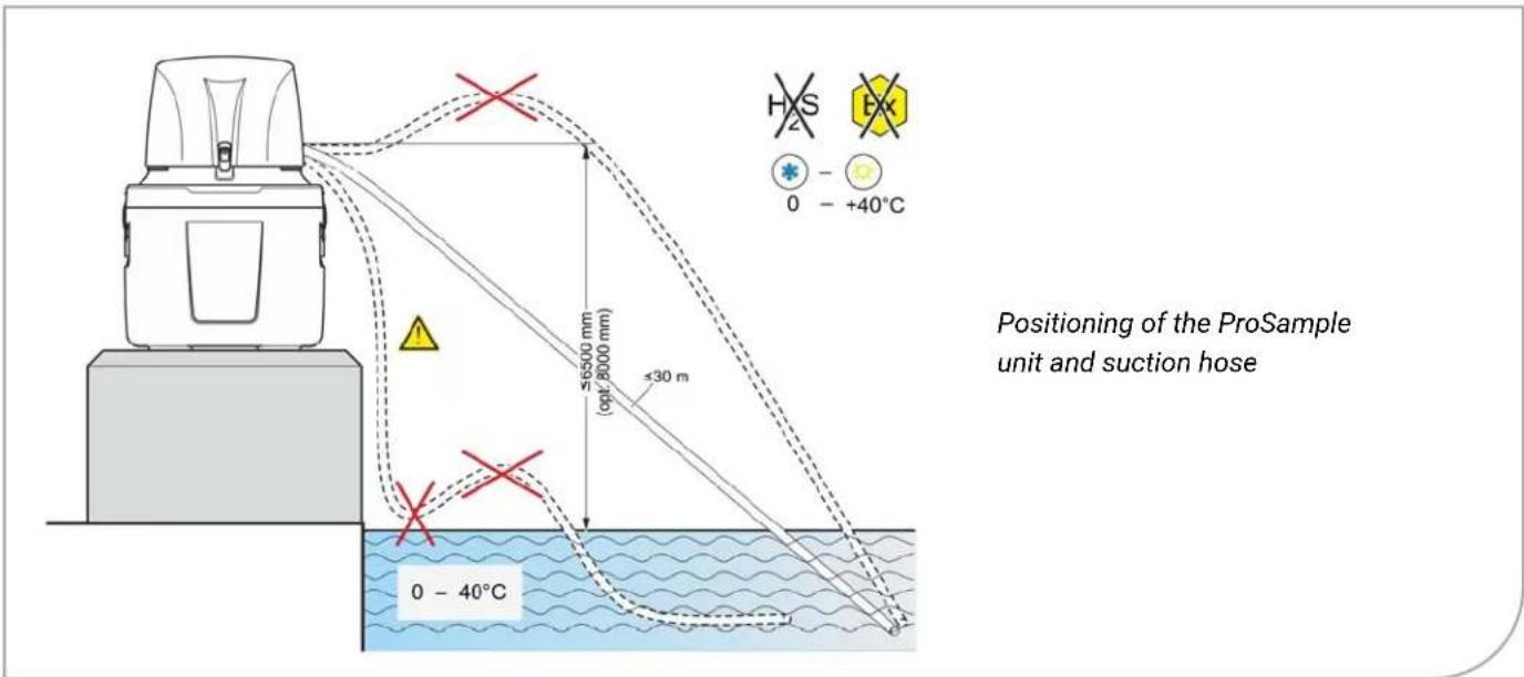
NOTE: Alternative third-party tubing can be used in place of the suction hose and intermediate tubing provided by YSI, but keep in mind that the material, gage, and other characteristics of the hose may affect the performance of the peristaltic pump.
3.3 Harness applications
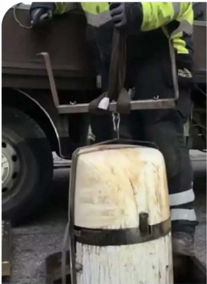
The suspension harness and bar can be used in applications where the ProSample needs to be suspended above the water, such as in a manhole or sewer, or below a bridge.
Suspension harnesses
YSI Item # Description Used with
| 0901072 | Suspension harness for ProSample PM and ProSample PM-12 | ProSample PM and PM-12 |
| 0901073 | Suspension harness for ProSample P and ProSample P-12 | ProSample P and P-12 |
| 0900045 | Suspension bar for harness | All ProSample models and suspension harnesses |
natural_image
Worker in safety gear handling a large white bucket outdoors near a vehicle (no visible text or symbols)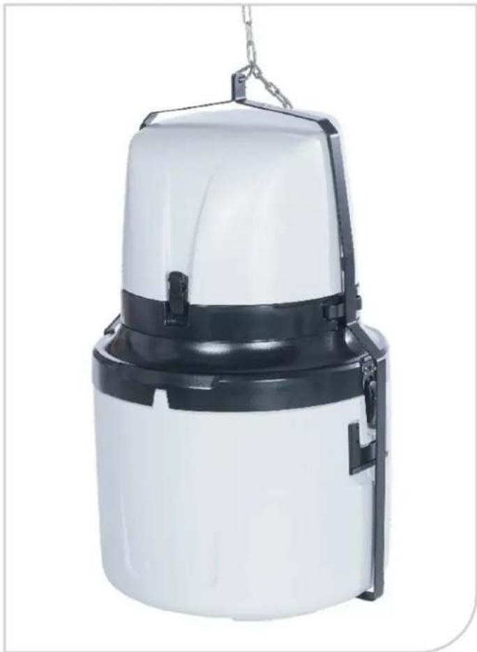
natural_image
White and black plastic air purifier device with hanging chain attachment (no text or symbols visible)NOTE: The above suction hose requirements also apply in applications with a harness; the hose should be no longer than 30 meters (excess length should be avoided).
4. Instrument setup and calibration
4.1 Installing the tubing
4.1.1 Peristaltic pump tube
The peristaltic pump tube does not come pre-installed in the ProSample. Two peristaltic tubes are included with each ProSample — one can be found under the lid of the ProSample, while the other is in the top tray of the ProSample packaging. To install the peristaltic pump tube:
- Turn the ProSample OFF and disconnect the battery.

WARNING: Do not attempt to install a peristaltic pump tube or service the pump while the ProSample is ON. The pump's moving components can cause serious injury.
- Use a flathead screwdriver to loosen the bolt outside the peristaltic pump cover.
- The peristaltic pump tube will connect to two tube connectors—one on the intermediate tube and the other on the composite sampling tube. Slide the connectors out of the side of the pump housing.
- Connect the peristaltic pump tube to each tube connector and slide the connectors back into the side of the pump housing.
- Place the peristaltic pump tube on the outside of the rollers of the peristaltic pump. You may need to turn the roller assembly to get the pump tube to sit properly in the pump housing. Refer to the image below.
- Close the cover to the peristaltic pump and tighten the bolt using a flathead screwdriver. Reconnect the battery.

natural_image
Close-up of a mechanical device with transparent tubing and black components, no visible text or symbolsInstalled pump tubing
4.1.2 Intermediate tube
The intermediate tube is the piece of tubing that connects the sample tube to the peristaltic pump tube. This tube passes in front of the two water sensors, which detect whether liquid is present in the tube and calculate the volume of liquid that has passed through the tube and into the sample bottles.
To install the intermediate tube:
- Connect the end of the intermediate tube to the sample tube by screwing the ends together.
- Insert the intermediate tube into the water sensor bracket below the ProSample battery.
- Lay the intermediate tube across the front of the ProSample.
- Insert the intermediate tube into the water sensor bracket, located by the peristaltic pump housing towards the front of the ProSample.
- Connect the intermediate tube to the peristaltic pump tube.

As shown in the diagram above, the intermediate tube must be installed for the peristaltic pump to function properly. If the intermediate tube is not installed properly during calibration and sampling, the ProSample may not pump the correct volumes of water.
4.2 Turning the ProSample on
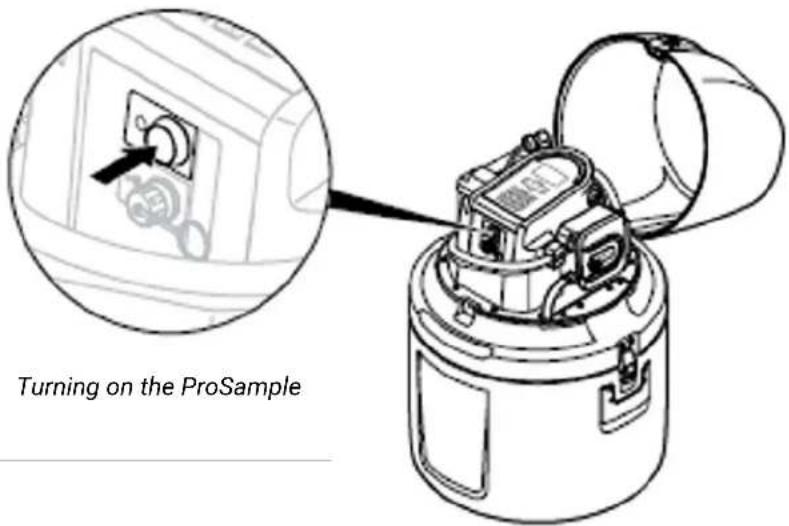
Press the ON/OFF button once to turn the ProSample on.
Press and release the button again to turn the unit off.
4.3 Sample bottle installation
Several bottle configurations are available for the ProSample P and ProSample P-12. Plastic (PE) and glass bottle sets are available. Please see Section 11, Replacement parts and accessories for a complete listing of available bottle sets.
If multiple bottles are installed in a ProSample P or ProSample P-12, a distributor arm must be installed. Please see Section 4.4, Installing a distributor arm.
A single 10-liter PE bottle can be placed in the ProSample PM and ProSample PM-12, but no other bottles can be used, as a distributor arm cannot be installed in the mini samplers.
4.3.1 Remove the top of the housing
Disconnect the clips that hold the top part of the housing to the rest of the instrument. Lift the top part of the housing off the instrument.

4.3.2 Prepare sample bottles and install
Ensure the sample bottles are clean and suitable before installing them in the bottom ProSample housing.
NOTE: A fixing plate is included with some bottle sets. If a fixing plate is included with your bottle set, it should also be installed at the bottom of the ProSample housing.

natural_image
Diagram of a mechanical component with a downward arrow indicating force or direction (no text or symbols)
natural_image
Technical line drawing of a mechanical component with a downward arrow indicating force or direction (no text or symbols)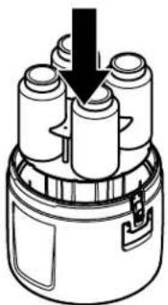
natural_image
Diagram of a cylindrical device with four cylindrical components and a downward arrow indicating force or movement (no text or symbols)
natural_image
Diagram of a cylindrical container with multiple cylindrical objects and an arrow pointing downward (no text or symbols)
natural_image
Diagram of a cylindrical device with internal components and a downward arrow indicating force or direction (no text or symbols)Installation of plastic (PE) bottles

natural_image
Diagram of a cylindrical battery with multiple cells and an arrow indicating downward motion (no text or symbols)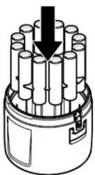
natural_image
Diagram of a cylindrical device with multiple tubes and a black arrow indicating direction (no text or symbols)
natural_image
Diagram of a cylindrical device with a downward arrow indicating compression or disassembly (no text or symbols present)Installation of glass bottles

natural_image
Cross-sectional diagram of a battery pack with internal components and a close-up inset showing a dial indicator (no text or symbols)Bottle #1 position and filling direction on the ProSample P and ProSample P-12 housing
At the bottom of the bottle housing is a number 1, marking the starting position for the first bottle. Install the subsequent bottles in the direction of the arrow. Installing the entire bottle set, even if only a fraction will be filled, ensures the bottle openings are properly positioned for the distributor arm to dispense the samples.
NOTE: Whether to use plastic or glass bottles depends on the medium sampled and the substances being analyzed. Glass is recommended for samples containing fuels, oils, pharmaceuticals, pesticides, and volatile organic compounds, but the customer should select between glass or plastic bottles at their discretion.
The ProSample housing is double walled to provide insulation for the samples. Once the sample bottle(s) are installed, the housing can be filled with ice or ice packs to help preserve the samples once collected. Take care not to allow ice water to enter the sample bottles.
4.3.3 Reattach the top of the housing
After installing the sample bottle(s), reattach the top part of the housing by lining it up with the bottom part of the housing. Use the clips on the side of the instrument to secure the top part of the housing to the bottom.
NOTE: The top part of the housing must properly align with the bottom. This is especially important when using a distributor arm with multiple bottles. If the top section is misaligned, the distributor arm will not behave as intended, and samples may be dispensed into the wrong bottles or missed entirely.

4.4 Distributor arm installation
Multiple bottles can be placed in the ProSample P and ProSample P-12, allowing for the collection of discrete samples. See Section 4.3, Sample bottle installation. A distributor arm must be installed if multiple bottles are to be used.
Two distributor arms are available for the ProSample P and ProSample P-12.
Each arm includes a preinstalled distributor tube.
- Item # 630112 is for the following bottle sets: 24 x 1 L PE, 8 x 2L glass, 12 x 950 mL glass, and 24 x 350 mL glass.
- Item # 630113 if for the following bottles sets: 4 x 4L PE and 8 x 2 L PE.
To install a distributor arm:
- Disconnect the composite sampling tube from the tube connector on the peristaltic pump housing.
- Flip over the top of the ProSample housing and remove the composite sampling tube.
- Remove the bolt with a red top. This covers the distributor arm axle.
- Place the distributor arm on the axle by lining up the pin with the hole on the distributor arm. Install the bolt with the red top and hand-tighten.
- There is a plastic bracket on the bottom of the ProSample housing that keeps the distributor tube in place during sampling — place the distribution tube into this plastic bracket.
- Slide the end of the distributor tube into the hole near the peristaltic pump.
- Reinstall the top of the ProSample housing.
NOTE: The top part of the housing must be in proper alignment with the bottom. If the top section is misaligned, the distributor arm will not behave as intended, and may dispense samples in the wrong bottles or miss the bottles entirely. Refer to the diagram in Section 4.3.3.
- Attach the distributor tube to the tube connector on the peristaltic pump housing.

4.5 Con gure key instrument settings
Seven key instrument settings are used for each program created.
From the Main Menu, navigate to the following screens to modify these key settings:

- Setup → Date/Time

- Setup → System Settings → Language

- Setup → System Settings → Distributor
ProSample P and ProSample P-12 only.
On the ProSample P and P-12, select the number of bottles (1, 4, 8, 12, or 24) that will be used (see Section 4.3, Sample bottle installation).
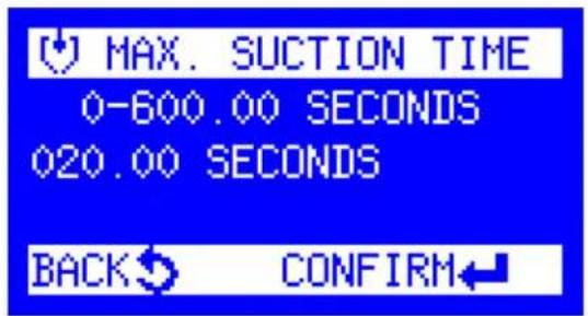
- Setup → System Settings → Max. Suction Time
The maximum suction time determines how long the ProSample will wait to display an error and shut off the pump when the instrument's sensors detect no water.

5. Setup → System Settings → Pre purge
The peristaltic pump pushes air through the suction hose before a new sample is collected to clear the moisture line and remove debris that may have collected around the suction hose opening. The pre-purge identifies how much air will be pushed through the suction hose.
The recommended pre-purge time depends on the length of the suction hose. To identify the exact amount of pre-purge time needed, set the pre-purge to a relatively high value (e.g., 10 seconds). Once a pre-purge cycle starts, use a stopwatch to determine how long it takes for air to be blown out of the suction hose. This amount of time can then be entered for the pre-purge.
NOTE: The ProSample can be manually purged by going to Diagnostics/Test → Component Test → Pump. Press the right arrow key to run the pump backward for purging.

6. Setup → System Settings → Post purge
Post-purge is the time the peristaltic pump pushes air through the line after a sample is collected. It is recommended that the post-purge be set to the same value as the pre-purge.
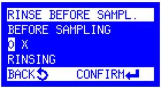
7. Setup → System Settings → Rinse Before Sampl.
Rinse Before Sampl. is the number of times the suction hose will be rinsed with sample solution before a sample is collected. Up to three rinses can be completed.
4.6 Water sensor calibration
The water sensors will need to be calibrated before the deployment of the sampler and subsequent volume calibration. Two capacitive sensors will be calibrated during this process: one by the peristaltic pump and the other underneath the battery pack.
It is crucial to ensure that the intermediate tube is firmly seated in both black sensor housings. If it is not, the calibration will fail, and the unit will not properly recognize water (See Section 4.1.2).
If the ProSample returns the code "ERROR LIQUID SENSOR," the water sensor calibration should be performed. This message indicates that dirt is likely in the tubing. Clean or replace the tubing, and perform the calibration to reset the water sensors.

To perform the water sensor calibration:
-
In Main Menu, scroll down to Setup. Press Enter.
-
Scroll down to Service Menu. Press Next.
-
Enter the password for the service menu. The password is the last two digits of the year and then the day in reverse. The ProSample shows the date in European date format: Day/Month/Year.
Example: The date is February 4, 2020. The last two digits of the year are 20, and the day is 04. The password is 0240.
- Scroll down to Calib. Watersensors. Press Next.

To perform the water sensor calibration: (continued)
-
Choose Empty Calibration.
-
Click the right arrow to Purge all of the water out of the intermediate tube, ensuring no water is in front of either of the sensors. Click the down arrow to Stop the purging.
Click the Enter button to Calibrate the water sensor with no water in the tube.
-
A message will appear verifying that the Empty Calibration has been completed.
-
Choose Full Calibration. Press Next.
-
Click the left arrow to Suction water into the intermediate tube, ensuring water is in front of both the sensors.
Click the down arrow to Stop the suctioning.
Click the green Enter button to Calibrate the water sensor with water in the tube
- A message will appear verifying that the Full Calibration has been completed.
After these steps have been completed, the water sensors will be calibrated, and the sampler will be ready for volume calibration.
4.7 Peristaltic pump volume calibration
The peristaltic pump must be calibrated at each sampling site, as the length and gradient of the suction hose impact the calibration result.
NOTE: Calibration in a lab setting can be completed to verify that the instrument is functioning properly, but it is still highly recommended that the instrument be recalibrated once at the sampling site.
4.7.1 Calibration containers
The ProSample is calibrated to an upper and lower volume, resulting in a 2-point calibration. The upper calibration will dispense a large volume of solution, typically over 1000 mL, whereas the lower calibration will dispense a small volume, around 250 mL. These are the default calibration volumes, which can be changed in the Service menu.
The volume dispensed during calibration will need to be accurately measured. It is recommended to obtain a large, plastic graduated cylinder and a small, plastic graduated cylinder when measuring the amount of solution dispensed during calibration.
4.7.2 Calibration procedure
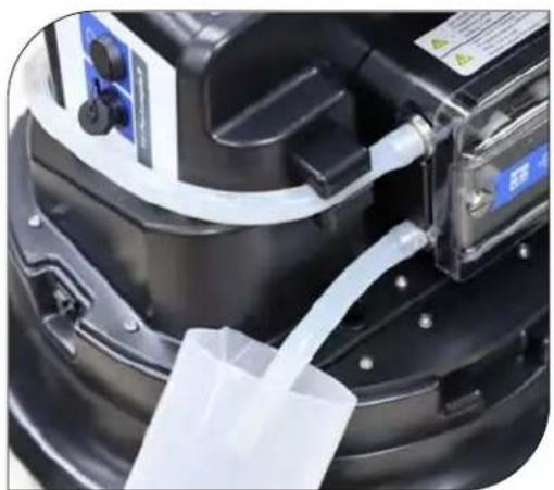
natural_image
Close-up of a mechanical device with a white plastic bag inserted, showing internal components and no visible text or symbols.Calibration with a large graduated cylinder
The following steps describe how to calibrate the ProSample peristaltic pump:
- Turn the ProSample OFF.
- Remove the top of the ProSample housing and flip it over.
- Remove the plastic 'elbow' piece from the end of the composite sampling tube. There is a plastic bracket that keeps the composite sampling tube in place during sampling – remove the tube from this bracket.
- Reinstall the top of the ProSample housing.
- Pull the composite sampling tube out of the ProSample housing. This will allow the solution to be poured directly into a graduated cylinder.
- Place a graduated cylinder with a volume of at least 2000 mL under the composite sampling tube.
NOTE: To calibrate at the sampling site, do not remove the composite sampling tube; instead, place the graduated cylinder at the end of the sampling tube as it will be installed to perform the calibration.
- Turn the ProSample ON.
- From the Main Menu, navigate to Setup → System Settings → Calibration Vol → Volume Calibration → Start Upper Volume. After pressing the Enter key, the ProSample will purge the line and then dispense a large amount of solution into the graduated cylinder.
- Do NOT remove the graduate cylinder underneath the sampling tube until Enter Actual Value is displayed on the screen. Enter the amount of solution that was dispensed and press the Enter key.
- The Start Lower Volume message should appear on the screen. Place a graduated cylinder with a volume of at least 250 mL under the composite sampling tube. After pressing the Enter key, the ProSample will purge the line and then dispense a small amount of solution into the graduated cylinder three separate times.
- Do NOT remove the graduated cylinder underneath the sampling tube until Enter Actual Value is displayed on the screen. Enter the amount of solution that was dispensed and press the Enter key.
4.7.3 Calibration check
The ProSample can dispense a user-specified amount of solution, allowing the pump calibration to be verified.
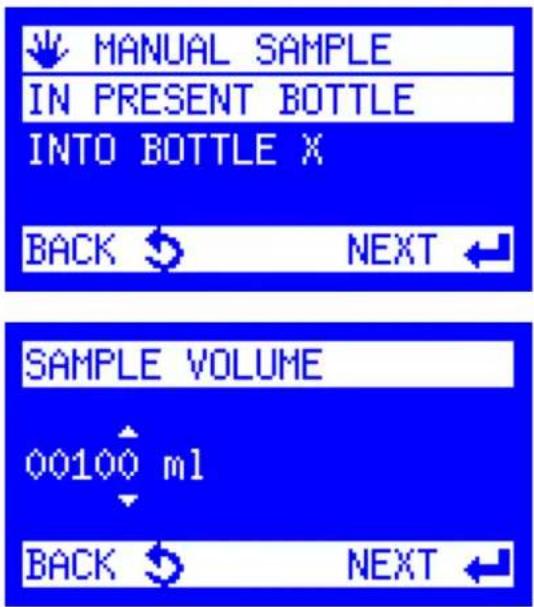
To complete a calibration check:
-
From the Main Menu, navigate to Manual Sample → In Present Bottle.
-
Place a suitable graduated cylinder underneath the sampling tube.
-
Enter the Sample Volume to be dispensed. It is recommended that you enter the amount of solution that will typically be dispensed when sampling. Press Enter.
-
Observe the amount of solution dispensed and recalibrate if needed.
4.7.4 After calibration and/or calibration check
- Turn OFF the ProSample.
- Insert the composite sampling tube into the hole in the ProSample housing.
- Remove the top of the ProSample housing and flip it over.
- Reinstall the plastic 'elbow' piece on the end of the composite sampling tube.
A plastic bracket keeps the tube in place during sampling—place the tube in this bracket.
- Reinstall the top of the ProSample housing.

natural_image
Close-up of a black mechanical component with a white PVC pipe fitting and a red indicator light (no text or symbols visible)5. Connecting analog, digital I/O, and SDI-12 devices
The ProSample P and ProSample PM can be configured to sample based on measurements/signals from analog and digital I/O devices, while the ProSample P-12 and ProSample PM-12 can additionally be configured to sample based on measurements from SDI-12 devices (e.g., EXO3 Sonde).
The ProSample P and PM have a single connector near the peristaltic pump that connects to the flow signal cable. The ProSample P-12 and PM-12 have two connectors; the top connector is for the flow signal cable, while the bottom connector is for the SDI-12 cable.
5.1 Flow signal cable wiring
The flow signal cable (Item # 630147) can send a digital, analog, or event signal to any ProSample model. One end of this cable has flying leads to be connected to an analog and/or digital device, while the other can be connected to the Signal Input on the ProSample. Please refer to the wire colors below when connecting the flow signal cable to the digital and/or analog device.

Flow signal wire colors
Wire Color Reference # Input Signal Purpose
| Brown | 1 | Analog + Connect to External Device Analog + |
| White | 2 | Analog - Connect to External Device Analog - |
| Grey | 3 | Common/Ground Connect to External Digital Device Common/Ground |
| Yellow | 4 | Digital For Triggering Flow Digital Programs (Section 6.7) ____ |
| Green | 5 | Event (Digital) For Triggering Event Digital Programs (Section 6.10) |
NOTE: The above table is only relevant if Item #630147 is used.
NOTE: The flow signal cable can connect an analog and digital device to the ProSample.
NOTE: Ensure that the 0/4-20mA device has proper power to collect readings across the range. The ProSample likely does not provide enough power for the instrument to record proper readings.
NOTE: Not all wires will be connected on all devices. To prevent accidental shorts in the electrical system, electrical tape should be used to cover all flying leads that are not used.
NOTE: The green and grey (ground) can be connected to a relay connection. When the relay closes, an event is triggered, and sampling will start. Two programs can be run, depending on which wires are connected to the relay loop – Flow Digital if the yellow wire is connected and Event Digital if the green wire is connected. Additional information on program types can be found in the Programming section of the manual.
5.1.1 Calibrating the analog signal
The analog signal coming to the ProSample from an analog device must be calibrated before configuring any analog trigger or program.


To calibrate the analog signal:
-
From the Main Menu, select Setup → System Settings → Analog Signal → Calibration
-
Analog 4-20 mA and Analog 0-20 mA are available options.
Highlight the appropriate option for your device and press the Enter key.
-
On your analog device, choose to output a mA value corresponding to the range's low value selected in step 2. For example, if 4-20 mA was selected in step 2, output a 4 mA signal from your analog device.
-
The Measured Value on the ProSample display should equal (or nearly equal) the desired mA value. Press the Enter key to confirm.
For example, if 4 mA is the signal sent from the analog device, the measured value might be equal to 3.9 mA. Please note the screenshot to the left was taken before the mA device sent a 4 mA signal to the ProSample.
-
On your analog device, choose to output 20 mA.
-
The Measured Value on the ProSample display should equal (or nearly equal) 20 mA. Press the Enter key to confirm.
-
The ProSample will display Calibration Done. Press the Enter key to return to the System Settings menu.
5.2 SDI-12 cable wiring
There are two SDI-12 cables available from YSI for use with the ProSample P-12 and ProSample PM-12.
5.2.1 SDI-12 cable with ying leads
One end of Item #630146 has flying leads for connecting to an SDI-12 device or a Signal Output Adapter for the SDI-12 device (e.g., EXO1 and EXO2 sondes). The other end of this cable is connected to the SDI-12 input on the ProSample P-12 or ProSample PM-12.
Please refer to the wire colors below when connecting the SDI-12 cable to the SDI-12 device and the manual for your SDI-12 device.
Flow signal wire colors
Wire Color Reference # Input Signal Purpose
| Brown | 1 | SDI-12 Data Connect to SDI-12 Data Terminal |
| White | 2 | SDI-12 Ground Connect to SDI-12 Common/Ground |
| Grey | 3 | 12 VDC Connect to 12 VDC |
| Yellow | 4 | Power Com/Gnd Connect to Power Common/Ground |
| Green | 5 | Error Signal Connect to Error Signal terminal on some SDI devices |
| Blue | 6 | 12 VDC Connect to aux 12 VDC on some SDI devices |
| Pink | 7 | Prog. Input Connect to Program Input on some SDI devices |
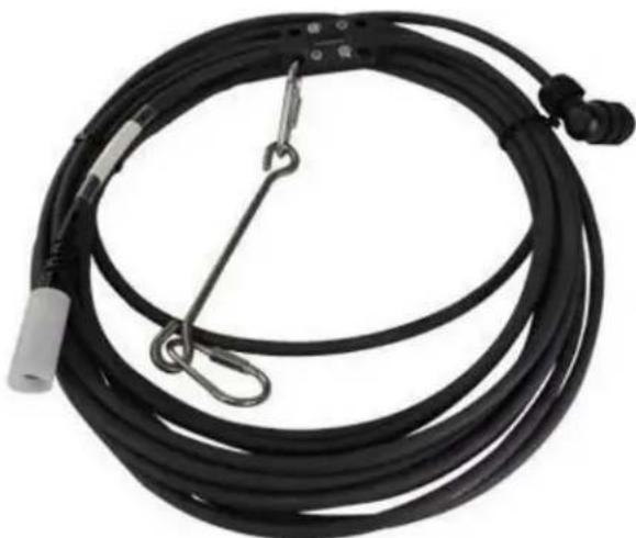
5.2.2 SDI-12 cable with EXO3 connector
620145 cables have all the connections necessary to connect a YSI EXO3 Sonde directly to the ProSample P-12 and ProSample PM-12. Therefore, no wiring is needed.
These cables are offered in lengths of 2, 4, 10, 15, and 33 meters.
NOTE: Be sure to configure the SDI-12 sensor output according to the sensor manual instructions. For example, the SDI-12 output of an EXO Sonde must be configured in Kor software.
natural_image
Coiled black cable with attached connectors and a terminal connector (no visible text or symbols)5.3 Triggering a program
The ProSample can automatically trigger a sampling program based on the signal input from a connected analog, digital, or SDI-12 device.
To use it, the trigger function must be activated in the Setup Menu. If the trigger function is disabled, the Triggering Menu will not appear in the System Settings.

To activate a trigger function:
-
In the Setup Menu, select Trigger Function.
-
Select Enabled.
-
The ProSample confirms that triggering is enabled. Press Enter.
5.3.1 Analog input trigger
A signal from an analog device can trigger all ProSample models. A flow signal cable (Item # 630147) must be connected to the analog device and the ProSample. As is shown in Section 5.1, Flow signal cable wiring, brown and white wires should be used when connecting the flow signal cable to the analog device.
NOTE: Ensure that the 0/4-20mA device has proper power to collect readings across the range.
The ProSample likely does not provide enough power for the instrument to record proper readings.
NOTE: Screenshots demonstrate an example setup. Settings should be adjusted for your specific application.
NOTE: The analog signal should be calibrated before running an analog program.
See Section 5.1.1, Calibrating the analog signal.
Trigger setup
The following procedure should be followed for setting up the analog parameter (up to 2) that will be used to trigger sampling:

- From the main menu, select
Setup → System Settings → Analog Units
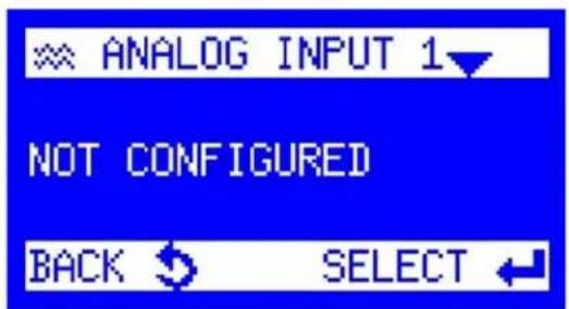
- Choose the input to be programmed.
Up to 2 Analog Inputs can be configured.

- Select units

Trigger setup:
(continued)
- Input the value that is recorded at 0/4 mA.
NOTE: Some analog devices report from 0-20 mA, and some report from 4-20 mA. Perform the analog signal calibration before running a program (Section 5.1.1).

- Input the value that is recorded at 20 mA.
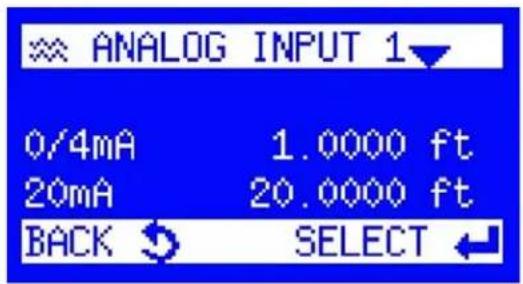
- The analog programming will be set and displayed. Select the Back button to return to the System Settings menu.
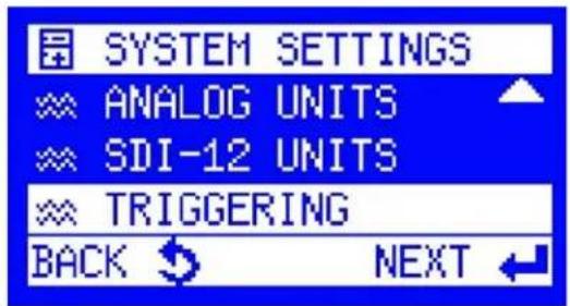
- From the System Settings menu, select the Triggering menu.


Trigger setup: (continued)
- Select the trigger channel to be configured by scrolling left or right and then Press Enter.
NOTE: Select a different input channel for each analog parameter that will be used to trigger sampling.
- Select the unit that the trigger will be based on.
NOTE: Remember that the unit selected here must match what was selected in Step 3.
- Select a High or Low Setpoint. The setpoint is the threshold value on which a trigger is based.
Low Setpoint: Any measurement value lower than the Low Setpoint will trigger samples to be taken.
As an example, if a Low Setpoint of 6 is entered, then sampling will be triggered once the pH lowers to 6 or less.
High Setpoint: Any measurement value higher than the High Setpoint will trigger samples to be taken.
For example, if a High Setpoint of 8 is entered, sampling will be triggered once the pH increases to 8 or more.
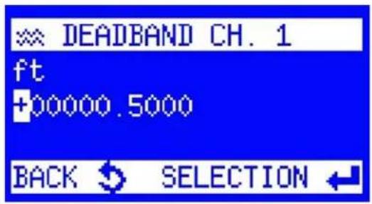
- Enter the setpoint value.
Trigger setup:
(continued)
- Enter the deadband value.
The deadband is important when using the Event method of sampling. Still, it is irrelevant to the continuous method (any value can be entered since ProSample will continue to run the program until completion).
If a Low Setpoint is entered, the deadband is the value the selected parameter must rise above before sampling no longer occurs (Event method only).
For example, if pH 6 is the Low Setpoint and a deadband of 0.5 is entered, the pH must rise above 6.5 before sampling no longer occurs.
If a High Setpoint is entered, the deadband is a value the selected parameter must drop below before sampling no longer occurs (Event method only).
For example, if pH 8 is the High Setpoint and a deadband of 0.5 is entered, the pH must drop below 7.5 before sampling no longer occurs.

- Action Channel is displayed.
To collect samples using the Event method, highlight Event, then press the Enter key.
To collect samples using the Continuous method, highlight the desired program and press the Enter key.
NOTE: Only the continuous method can be used if more than one parameter is set to trigger sampling.

- If the analog device is already attached, the reading from the device will appear on the Trigger (CH) menu screen after a few minutes.
The first line shows the set trigger value. The second line shows the selected setpoint and the action. The third line shows the current value. If the value triggers the program, an exclamation mark is displayed after the value.
5.3.2 Digital input trigger
A pulse from a digital I/O device can trigger all ProSample models. A flow signal cable (Item # 630147) must be connected to the digital device and the ProSample. As is shown in Section 5.1 Flow signal cable wiring, grey and either yellow or green wires should be used when connecting the flow signal cable to the digital device.
NOTE: The yellow wire is connected when a Flow Digital program is used; the green wire is connected when an Event Digital program is used. Please see the programming section for additional information.
NOTE: Screenshots demonstrate an example setup. Settings should be adjusted for your specific application.
NOTE: Most trigger setups occur in the Digital I/O device. For additional information on how to set up a digital output, please refer to your device's user manual.
NOTE: The ProSample needs a pulse length of 50 mS or higher to detect a digital pulse.
Trigger setup
The ProSample is designed to collect samples when a trigger pulse is received and will trigger either of the previously mentioned programs. The following procedure should be followed to verify that the ProSample is receiving a pulse from the external Digital I/O device:
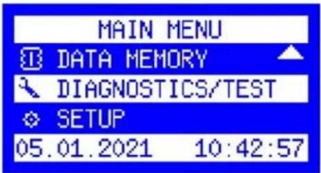
- From the main menu, select "Diagnostics/Test"

- Select "Digital Inputs"
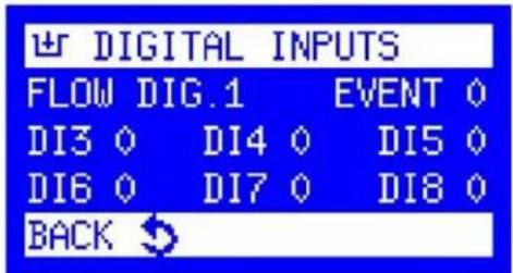
- When the ProSample detects a Trigger Pulse from the Digital I/O device with the yellow wire connected, the "Flow Dig" number will change momentarily from 0 to 1.

If the green Event wire is connected, the "Event" number will change momentarily from 0 to 1. The duration of this change will be the pulse length set during the Digital I/O device setup.
NOTE: For testing and troubleshooting, it is recommended that the pulse length be set to >2000 mS but can be altered after connections have been verified.
5.3.3 SDI-12 Input trigger
The ProSample P-12 and ProSample PM-12 are the only ProSample models triggered through direct communication with an SDI-12 device. When connecting the SDI-12 device to the ProSample, please refer to Section 5.2, SDI-12 cable wiring.
To use an SDI-12 device, the user must configure it properly before programming the ProSample P-12 or ProSample PM-12. Please consult the user manual of your SDI-12 device regarding proper configuration.
The SDI-12 input trigger should call a Time-Paced (Section 6.6) or Event Time (Section 6.9) program.
Up to four SDI-12 parameters can be configured to trigger sampling. If an "AND" scenario with multiple parameters is needed to trigger sampling (e.g., the solution must have pH > 8 AND turbidity > 124 FNU for sampling to begin), then a data logger must be used to trigger sampling (see Digital pulse input event).
There are two different methods of programming the ProSample to stop sampling – continuous and event.
Continuous Method: If the trigger criteria are met, sampling will occur until the program is complete, even if the trigger criteria are no longer met while the program is active. Only the continuous method can be used if more than one SDI-12 parameter is set to trigger sampling.
Event Method: Sampling will only occur when the trigger criteria are met. Sampling will pause if the trigger criteria are no longer met while the program is active. Sampling will continue if and when the trigger criteria are met again until the program is complete.
Step # 16 in the following procedure determines which method is utilized.
NOTE: Screen shots demonstrate an example setup. Settings should be adjusted for your specific application.
NOTE: If using the continuous method, it is recommended to program the ProSample first, place the SDI-12 device in the sampling environment, and then connect the SDI-12 device to the ProSample. This is recommended because the program will be triggered if the trigger criteria are met (i.e., the program is not started by going to Program → Start).
Trigger Setup
The following procedure should be followed for each SDI-12 parameter (up to 4) that will be used to trigger sampling:

- From the main menu, select
Setup → System Settings → SDI-12 Units
Trigger setup: (continued)

- Select Units.

3.Input the SDI-12 Address through which the connected device is communicating.
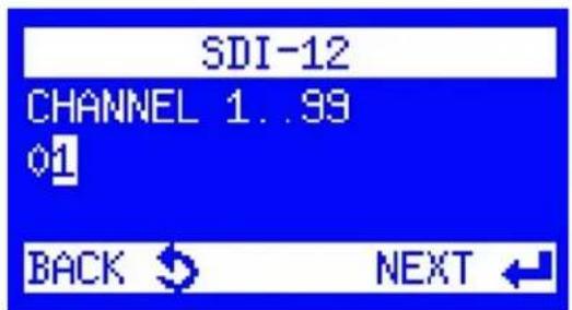
- Input the SDI-12 channel that the desired parameter is communicated through.

- Select the unit that the parameter reports in. Triggering programs are based on the unit selected.
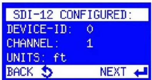
- The SDI-12 channel has been configured, and the results are displayed.
Click Next to return to the System Settings menu.
Trigger setup:
(continued)
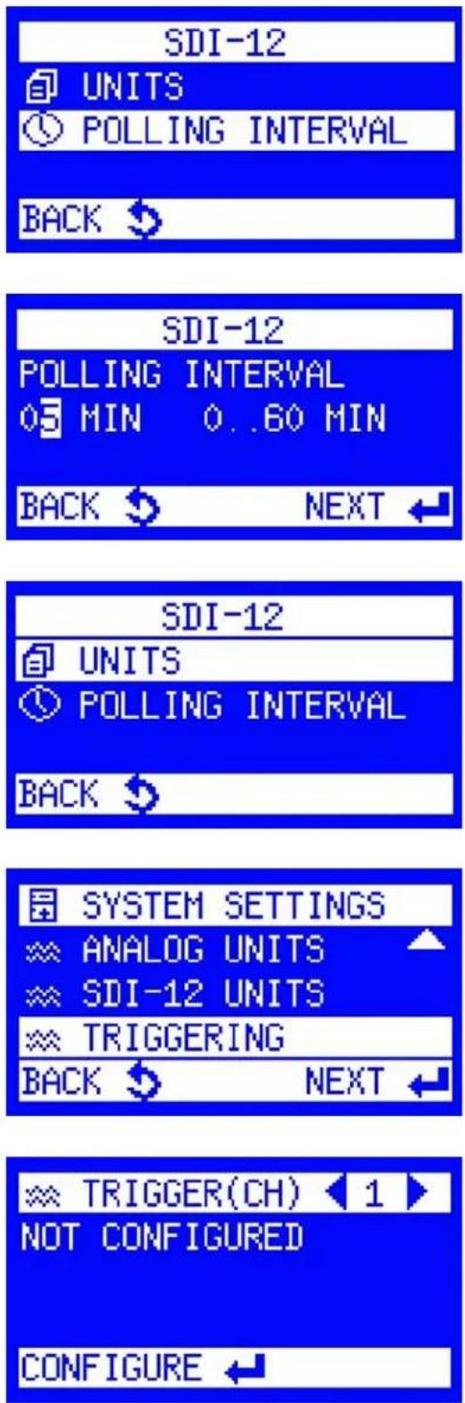
- Return to the SDI-12 Units menu and select Polling Interval.
- Adjust how often the SDI-12 sensor should be scanned. Click Next to return to the SDI-12 Units menu.
- Click Back to return to the System Settings menu.
- Select Triggering.
- Scroll left or right to select the trigger channel to be configured, and then click the enter button on that channel.
NOTE: Select a different input channel for each SDI-12 parameter that will trigger sampling. The input channel selected for each parameter should match the channel configured on the SDI-12 device.



Trigger setup: (continued)
- Select the unit that the trigger will be based on.
NOTE: The unit selected here must match what was selected in Step 5.
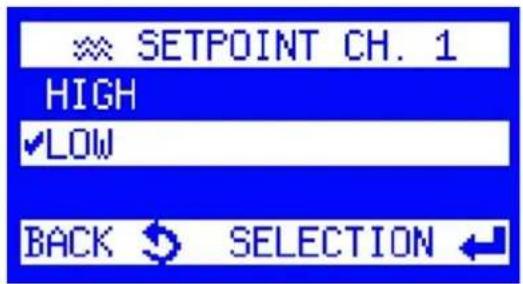
- Select a High or Low Setpoint. The set point is the threshold value that a trigger is based on.
Low Setpoint: Any measurement value lower than the Low Setpoint will trigger samples to be taken. For example, if a Low Setpoint of 6 is entered, sampling will be triggered once the pH lowers to 6 or less.
High Setpoint: Any measurement value higher than the High Setpoint will trigger samples to be taken. For example, if a High Setpoint of 8 is entered, sampling will be triggered once the pH increases to 8 or more.
-
Type in the setpoint value.
-
Type in the deadband value and press Enter.
NOTE: Deadband is important when using the Event method of sampling, but the deadband is irrelevant with the Continuous method (any value can be entered since ProSample will continue to run the program until completion).
If a Low Setpoint is entered, the deadband is the value the selected parameter must rise above before sampling no longer occurs (Event method only). For example, if pH 6 is the Low Setpoint and a deadband of 0.5 is entered, the pH must rise above 6.5 before sampling no longer occurs.
If a High Setpoint is entered, the deadband is a value the selected parameter must drop below before sampling no longer occurs (Event method only). For example, if pH 8 is the High Setpoint and a deadband of 0.5 is entered, the pH must drop below 7.5 before sampling no longer occurs.


Trigger setup: (continued)
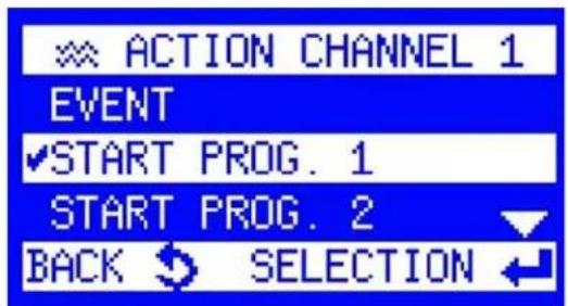
- Action Channel is displayed.
To collect samples using the Event method, highlight Event, then press the Enter key.
To collect samples using the Continuous method, highlight the desired program to start and press the Enter key.
NOTE: If more than one SDI-12 parameter is set to trigger sampling, only the continuous method can be used.
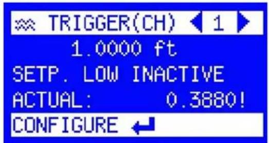
- If the SDI-12 device is connected and powered on, its reading will appear on the Trigger (CH) menu screen. The first line shows the set trigger value.
The second line shows the selected setpoint and the action. The third line shows the current value. If the value triggers the program, an exclamation mark is displayed after the value.
NOTE: If the third line is not displayed, the set trigger value is not recognized. This means that a unit that was not configured in the SDI-12 Units menu has been selected.
-
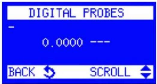
After configuration, check whether the ProSample recognizes the SDI-12 input correctly. From the main menu, navigate to Diagnostics/Test → Digital Probes
-
Check the units, SDI-12 address (Device ID), and channel number.
NOTE: The data is populated once the ProSample receives a signal from the probe. This time period depends on the Polling Interval.
NOTE: No connection to the probe has been established if nothing is displayed. In this case, please ensure your probe is wired correctly.
6. Sampling programs
The ProSample can be used in various scenarios, from simple time-paced samples to complex trigger-based samples. This programming section reviews how each program can be set up to collect samples. Please get in touch with YSI Technical Support if you need additional assistance in understanding how to set up a program.
NOTE: The settings modified in Section 4.5 Configure key instrument settings will be applied to every program, so it is important to carefully set them before starting any program.
All ProSample models can run each program type described below; however, only ProSample P-12 and PM-12 can be connected to and triggered by an SDI-12 device. It is important to ensure that the triggers for these programs are set up appropriately. Please refer to the Triggering section for information on how to set up external triggering devices.
NOTE: Program Pause can be used if a continuous program runs with time between skips, such as Monday through Friday sample only and no samples on the weekend. See Section 6.5.
6.1 Sampling scenario list and descriptions
Scenario Description
| Time Paced | The ProSample will collect samples at a user-defined time interval. |
| Flow Digital | Requires an external Digital I/O device and collects a sample after every user-defined number of pulses. It continues until all bottles are filled or a time threshold has been reached. |
| Flow Analog | Requires a 0/4-20mA analog device and collects a sample after the sensor passes a certain amount of computed flow. It continues until all bottles are filled or a time threshold has been reached. |
| Event Time | Requires an analog or SDI-12 device and collects a sample every user-defined time interval after a user-defined threshold has been met. Sampling ceases when the threshold is no longer met. |
| Event Digital | Requires an external Digital I/O device connected to the Event wire and starts a program based on when digital events are received. |
| Event Analog | Requires a 0/4-20mA analog device and converts the signal from that device into a flow and collects samples when a user-defined amount of flow has passed by the sensor. |
| Variable Time | Requires a 0/4-20mA analog device and converts the signal from that device into a flow. At specific time intervals, the sampler collects differing amounts of sample water depending on the amount of flow present. |
| Batch Sampling | Requires an external device to trigger an Event. When an Event starts, samples are placed into a bottle based on a time interval. When the Event threshold is no longer met, sampling ceases. If the threshold is met again, sampling resumes in the same bottle where the earlier sampling was left off. |
6.2 Main menu tree
NOTE: The ProSample does not have an internal temperature sensor.
Menu items related to Internal Temperature in the firmware are not relevant to the ProSample.
NOTICE: Change settings at user discretion
Programs
| Status/Stop | Info Display of program details | |
| Pause Interruption of | the running program (max 120 minutes) | |
| Stop Stop the current | program or all programs | |
| Start | Immediately Start program immediately | |
| Date/Time Start program with date/time (dd:mm:yyyy, hh:mm) | ||
| Weekday/Time Start program with weekday/time (day; hh:mm) | ||
| Change Program No [xx] | Change operating modes:TIMEFLOW DIGITALFLOW ANALOGEVENT TIMEEVENT DIGITALEVENT ANALOGVARIABLE TIMEBATCH SAMPLING | |
Manual sample
| In present bottle Sample extraction into PRESENT bottle | |
| Into bottle X Sample extraction into selectable bottle X |
Data memory
| Sampling data Display of program details | |
| Temperature data Interruption of the running program (max 120 minutes) | |
| Bottle protocol | Data of each bottle (e.g. requested/taken samples) |
| Bottle archive | Archive of the last 50 bottle protocols for the last 50 program cycles |
Data memory (continued)
| System Settings | Rinse before sampling | Option to rinse intake line with source liquid prior to each sample, up to 3 rinses. Default is no rinses. |
| Calibration vol Volume | calibration for peristaltic pump | |
| Log entires | Set of the Log entires. Log interval for Temp. board and PT1000 can be adjusted 1-60 min. | |
| Internal temperature Not relevant | ||
| Fault signal Possibly to invert the output | ||
| Analog signal | Selection:• 0-20 mA• 4-20 mACalibration (adjustment with the signal of plant) | |
| Display | • Always switched on• Switch off after certain time (0-999 sec.)• Limit value (1-20°C)• Delay time (1-60 min.)• Delay time (1-60 min.) | |
| Status LED Enable or disable the LED indicator on the front of the ProSample. | ||
| Pause duration | Program can be interrupted for 10-120 min., for example, for cleaning. After expiry of the time entered the program is automatically resumed. | |
| Prog. inputs | Programmable inputs: input signal to start a program e.g. via an external pulse. Four inputs are available. | |
| Min. Sample volume Setting of the min. sample volume which shall be taken. Default is 1 mL. | ||
| Max. Sample volume | Setting of the max. sample volume which shall be taken. Default is 250 mL. | |
| Sleep Mode | Active | If the sleep mode has been activated and the program is to be started in 20 min. at the earliest, the message, "Attention device switches to sleep mode" is displayed for 30 sec. Thereafter, the display is switched off and only activated again 2 min. prior to the program start. |
| Inactive Sleep mode is deactivated | ||
| Password | Change password In general the password can be changed | |
| Change settings A password for settings can be entered | ||
| Change programs A password for changing programs can be entered | ||
| Stop programs A password for stopping programs can be entered | ||
| Service | Setting of base parameters (only to be done by a service technician) (Password protected) (yy:dd) | |
6.3 Program start options
After a sample program has been set up according to the instructions for one of the eight sampling scenarios detailed in Section 6, there are two ways to start the program. One is to use an external device to trigger the program start, using the directions in Section 5.3. The other method is manually starting a program from the 'Program Start' menu.
NOTE: Ensure the unit's date and time are correct. See Configure Key Instrument Settings in Section 4.5.
After selecting a sample program in one of the 12 program slots by using the left and right arrow keys and clicking 'Next,' there are several options to start the program:
Immediately: The program will start as soon as the programming is completed.
Date/Time: Select a calendar date and time for when the program will start. Format: dd:mm:yyyy hh:mm.
Weekday/Time: Select a day of the week and time that the program will start. Format: day; hh:mm.
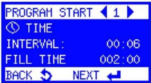
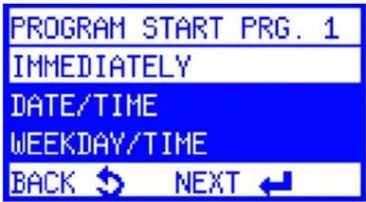
The Weekday/Time option can also be used to start the program at a past or future time to maintain a 24-hour daily cycle. This allows for a fixed assignment of bottle number and sample time of day.
For example, suppose today is May 10th and the program starts at 11:20 a.m., filling 12 bottles with a 2-hour bottle fill time (in a ProSample P or P-12 with a distributor arm), but the user wants the 24-hour sampling cycle to begin at 8:00 a.m. The weekday/time can be set to 10.05.yyyy 08:00.
The software automatically calculates which bottle position the distributor arm must be placed in according to the programmed number of bottles and bottle fill time, along with the current time in relation to the desired start time (Bottle 2, in this case). The ProSample distributor arm automatically changes to this position at the first requested sample extraction.
NOTE: When manually starting a Flow Digital or Event Digital program, it will start at the programmed time, but samples will not be collected until the set number of pulses are sent to the ProSample.
6.4 Program end options
After defining the start conditions, the program end can be set as follows:
After 1 Run: The program will end after one full completion (e.g., bottle fill time is reached in a single time).
After X Runs: The program will end after multiple cycles have been completed (e.g., bottle fill time is reached two times).
Continuous Operation: The program repeats continuously until the sampling program is manually stopped.
Date/Time: A date and time is selected for when the program should stop running. The program will repeat multiple times until this date and time.

6.5 Program status
The status of active and inactive programs can be viewed in the program status menu.
The status of programs 1 – 12 can be checked by pressing the left/right arrow keys and pressing Enter on a program.
6.5.1 Status/Stop
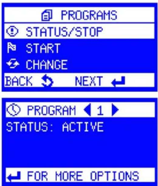
Status Active: Program has been started and is active
Status Inactive: Program has not been started
6.5.1 Status/Stop
(continued)
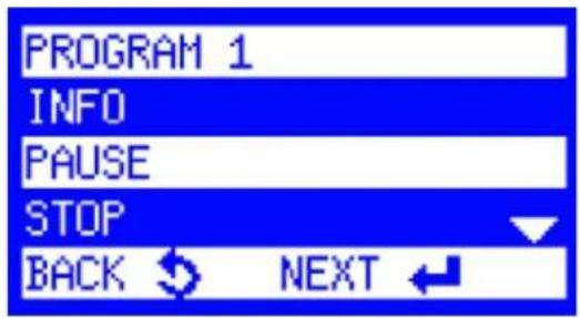
Info:
Displays information regarding the program currently running: current bottle, samples requested and samples taken, next sample extraction, or bottle change. Press the up/down arrow keys to display more information.
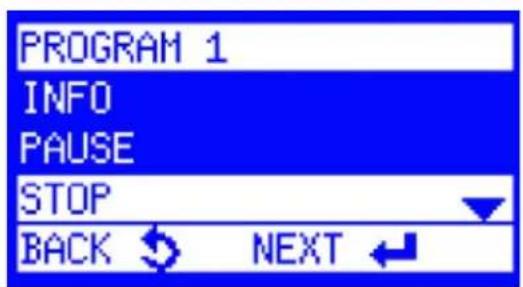
Pause:
The program can be interrupted for 10-120 minutes (e.g., for cleaning). The exact time can be entered in the Settings menu. The pause can be terminated manually, or it is automatically terminated after the entered xxx minutes.
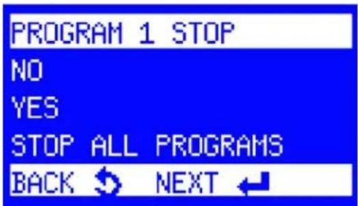
Stop:
An active program can be stopped/aborted. If several programs are active, all programs can be stopped at the same time.
6.6 Time-paced
The ProSample will collect samples at a user-defined interval. All ProSample models can be used for this sampling scenario. A flow signal cable and/or SDI-12 cable are not required to run this program.
NOTE: The settings modified in Section 4.5 Configure key instrument settings will be applied to every program, so they must be carefully set before starting any program.
NOTE: Screenshots demonstrate an example setup. Settings should be adjusted for your specific application.

- From the Main Menu, select Program → Change.
Choose the program you would like to modify by using the left and right arrow keys. In this example, we will modify Program # 1. Press the Enter key to begin modifying the program.

- Highlight Time and press the Enter key.
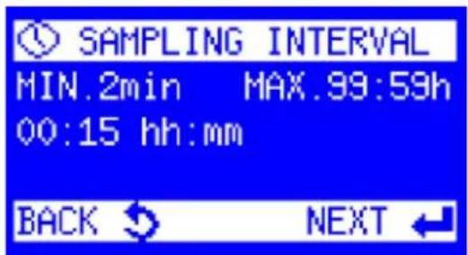
- Enter a Sampling Interval.
This determines how often a sample will be collected and is user-set based on the application and sampling requirements. Press the Enter key to begin modifying the program.

- The Sample Volume is displayed.
This is the amount of sample that will be collected at each Sampling Interval. The user sets the Sample Volume based on the application and sampling requirements. Press the Enter key to begin modifying the program.
Time-paced: (continued)

- The Bottle Fill Time is displayed.
NOTICE: If using a composite bottle, Bottle Fill Time determines how long the program will run. As an example, if the Sampling Interval is set to 15 minutes, the Sample Volume is set to 100 mL, and the Bottle Fill Time is set to 2 hours. The ProSample will collect 100 mL of sample every 15 minutes for 2 hours, resulting in a total of 800 mL of sample collected.
If using discrete sampling bottles (i.e., more than one bottle is used), Bottle Fill Time determines how many times each bottle in the program will be filled. As an example, if the Sampling Interval is set to 15 minutes, the Sample Volume is set to 100 ~mL , and the Bottle Fill Time is set to 15 minutes (i.e., the same as the Sampling Interval), then each bottle is only filled once, and each bottle will contain 100 ~mL of sample. The entire length of the program is determined by the number of bottles that will be filled (see steps 5-7). Therefore, every 15 minutes, a different bottle will be filled. If there are 6 bottles the program length will be 90 minutes.
As another example of discrete sampling, if the Sampling Interval is set to 15 minutes, the Sample Volume is set to 100 ~mL , and the Bottle Fill Time is set to 45 minutes (i.e., three times longer than the Sampling Time), then each bottle is filled three times, and each bottle will contain 300 ~mL of sample.

- The Info screen is displayed.
If there is only one bottle installed (composite sampling):
- Select Settings Complete, and the ProSample will return to the Programs menu. Skip to step 10.
If there is a distributor arm and multiple bottles installed (discrete sampling):
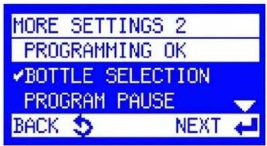
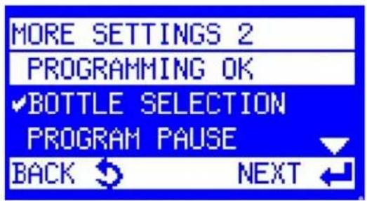
- Select More Settings → Bottle Selection.
If you want to fill all bottles in the sampler, select All Bottles. Return to the More Settings menu by pressing the Back key once, then select Programming OK. Skip to step 10.
If you only want to fill certain bottles, select Bottle Selection, then continue with step 7 below.


Time-paced: (continued)
-
First Bottle is displayed if the ProSample has more than one bottle installed. Enter the bottle number in which the first sample should be placed. Press the Enter key.
-
Last Bottle is displayed. Enter the bottle number of the last sample that should be placed. Press the Enter key.
-
The More Settings menu is displayed. Highlight Programming OK and press the Enter key.
-
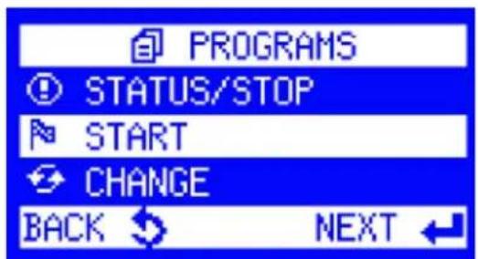
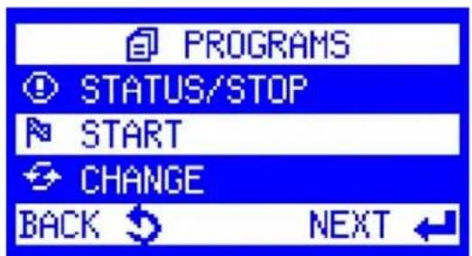
The Programs menu is displayed. To run the program, highlight Start and press the Enter key.
NOTE: Ensure the pump is calibrated before running any programs. Please see Section 4.7 Peristaltic pump calibration.
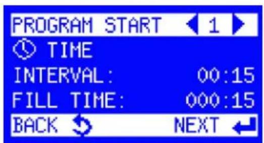
- Use the right arrow key to select the program to run. Press the Enter key. Reference Section 6.3 and Section 6.4 to set the program's start and end times.
6.7 Flow digital
This program requires a digital outputting device like a data logger to be connected to the sampler. Please see the Wiring section for information on how to connect this device. In this scenario, the data logger or other device will compute the flow and send a trigger pulse to the ProSample when it is time to start collecting samples. After every programmed number of pulses to the ProSample, the sampler will collect a sample.

- Navigate to the main menu screen and select Programs.
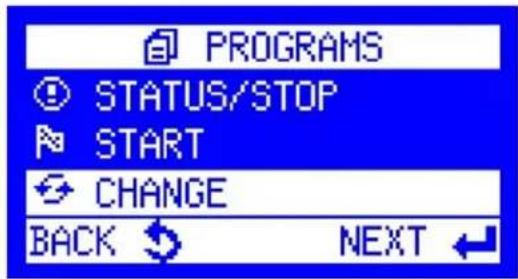
- Scroll down to Change and select Next.
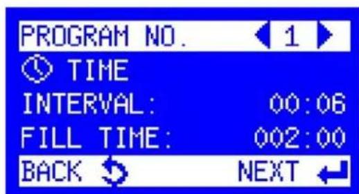
- Use the left and right arrow keys to navigate to the desired program to change. Select the Next key to begin editing the program.

- Scroll down to Flow Digital and select Next.
Flow digital:
(continued)
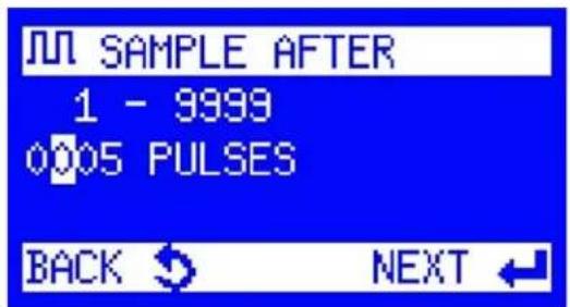
- Enter the number of trigger pulses between collected samples.
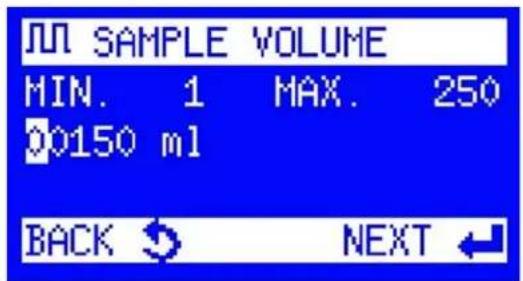
- Enter the Sample Volume that should be collected during each sample pull.

- Choose a Fill Mode

a. Time Related: Choose how long it will take for the bottle to fill.

i. Enter the Limitation of Samples. This is the maximum amount of sample that should be collected into a single bottle. Select Next.



Flow digital:
(continued)
ii. Choose a Function that determines what will happen to a sample if there is more solution to be placed in a bottle than the bottle can hold.
Drop Samples:
Stop collecting samples and drop the extra amount.
Switch to Next Bottle:
Collect the sample in the next available bottle.
b. Sample Related:
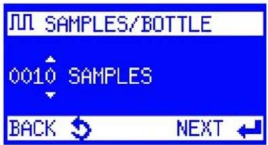
Choose the number of samples that should fill each bottle.
For example, if 24 1L discrete bottles are used and 150 mL samples are collected, a maximum of six samples should be collected into a single bottle; otherwise, the bottle will overfill.
- The Info screen is displayed.
a. If only one bottle is installed (composite sampling), select Settings Complete, and the ProSample will return to the Programs menu. Proceed to Step 12.
b. If a distributor arm and multiple bottles are installed (discrete sampling), select More Settings.
A. Select Bottle Selection.
B. If you want to fill all bottles in the sampler, select All Bottles. Press the Back key once to return to the More Settings menu, then select Programming OK. Proceed to Step 12.
C. If you only want to fill certain bottles, select Bottle Selection.


Flow digital: (continued)
-
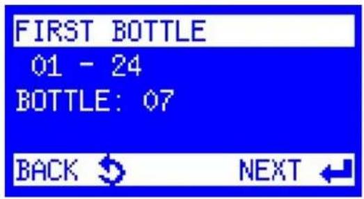
First Bottle is displayed if the ProSample has more than one bottle installed. Enter the bottle number in which the first sample should be placed. Press the Enter key.
-
Last Bottle is displayed. Enter the bottle number of the last sample that should be placed. Press the Enter key.
-
The More Settings menu is displayed. Highlight Programming OK and press the Enter key.
-
The Program menu is displayed. Highlight Start and press the Enter key.
-
Use the arrows to select the program to run. Press the Enter key. To set the program's start and end times, reference Section 6.3 and Section 6.4.
NOTE: Ensure the pump is calibrated before running any programs. Please see Section 4.7 Peristaltic pump calibration.
NOTE: The program will start as soon as possible at the selected start time, but no sample will be collected until the set number of pulses is sent to the ProSample.
6.8 Flow analog
This program requires a 0/4-20mA analog device to be connected to the sampler. Please see the Wiring section for information on how to connect this device. The ProSample will convert the analog signal into a flow, with samples collected every time the sampler passes a programmed amount of flow. Flow data from this programming method is stored in the ProSample for viewing later in the YSI Connect software.

- Navigate to the main menu screen and select Programs.

- Scroll down to Change and select Next.

- Use the left and right arrow keys to navigate to the desired program to change. Select the Next key to begin editing the program.

- Scroll down to Flow Analog and select Next.


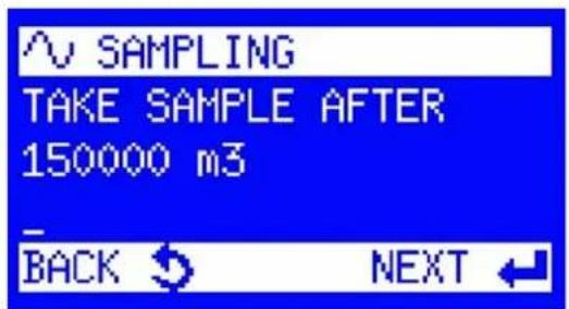
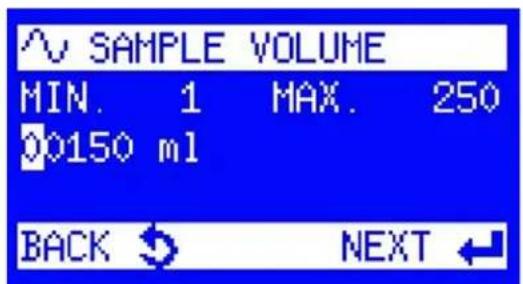
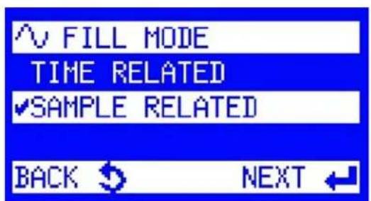
Flow analog: (continued)
- Select the Unit that the flow pacing will be measured in.
NOTE: To convert CFS to m^3/s , multiply by 0.02832.
- Set the maximum flow corresponding to the analog signal at 20 mA. Select Next
NOTE: The discharge rating programmed inside the ProSample is a linear equation, starting at zero flow at 0/4mA and extending to the value corresponding to 20 mA. Example: 4 mA = 0 m³/s. 20 mA = 10,000 m³/s. Value at 12 mA = 5,000 m³/s.
-
Set the Flow Pacing. Flow Pacing is the amount of water that passes by the ProSample between samples. Select Next.
-
The Sample Volume is displayed. This is the amount of sample that will be collected after the volume determined in the Flow Pacing step has passed. Select Next.
-
Choose the Fill Mode: Time Related or Sample Related
Flow analog:
(continued)


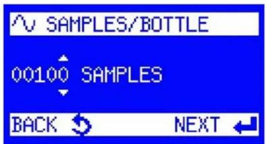
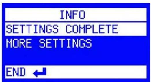
a. Time Related:
Choose how long it will take for the bottle to fill.
i. Enter the Limitation of Samples. This is the maximum amount of sample that should be collected into a single bottle. Select Next.
ii. Choose a Function that determines what will happen to a sample if there is more solution to be placed in a bottle than the bottle can hold.
Drop Samples:
Stop collecting samples and drop the extra amount.
Switch to Next Bottle:
Collect the sample in the next available bottle.
b. Sample Related:
Choose the number of samples that should fill each bottle.
For example, if 24 L discrete bottles are used and 150 mL samples are collected, a maximum of six samples should be collected into a single bottle; otherwise, the bottle will overfill.
- The Info screen is displayed.
a. If only one bottle is installed (composite sampling), select Settings Complete, and the ProSample will return to the Programs menu. Proceed to Step 14.
b. If a distributor arm and multiple bottles are installed (discrete sampling), select More Settings.
Flow analog:
(continued)
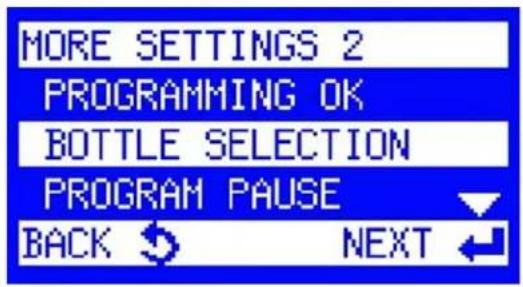
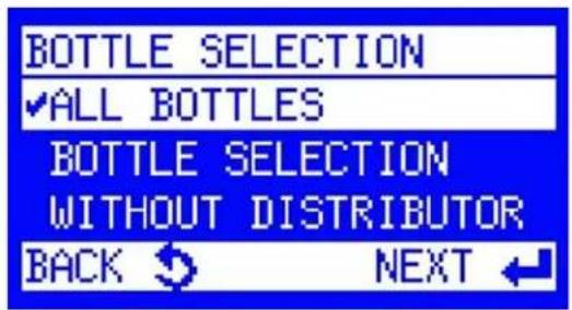

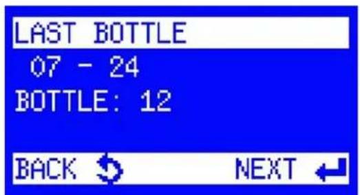

i. Select Bottle Selection.
A. If you want to fill all bottles in the sampler, select All Bottles. Press the Back key once to return to the More Settings menu, then select Programming OK. Proceed to Step 14.
B. If you only want to fill certain bottles, select Bottle Selection.
-
First Bottle is displayed if the ProSample has more than one bottle installed. Enter the bottle number in which the first sample should be placed. Press the Enter key.
-
Last Bottle is displayed. Enter the bottle number of the last sample that should be placed. Press the Enter key.
-
The More Settings menu is displayed. Highlight Programming OK and press the Enter key.
Flow analog:
(continued)
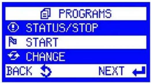
- The Program menu is displayed. Highlight Start and press the Enter key.
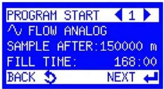
- Use the arrows to select the program to run. Press the Enter key. To set the program's start and end times, Reference Section 6.3 and Section 6.4.
NOTE: Ensure the pump is calibrated before running any programs.
Please see Section 4.7 Peristaltic pump calibration.
6.9 Event time
This sampling program will not run until an external device reaches a programmed threshold from the trigger sections. Please see the Wiring section for information on how to connect an external device. The program will run at exact time intervals until the trigger threshold is no longer met. For more information on how to set up an Event trigger, please reference Section 5.3.

- Navigate to the main menu screen and select Programs.

- Scroll down to Change and select Next.
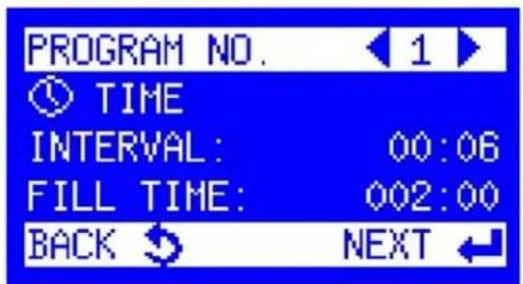
- Use the left and right arrow keys to navigate to the desired program to change. Select the Next key to begin editing the program.

- Scroll down to Event Time and select Next.


NOTE: Depending on the length of the event, times or volumes may need to be adjusted to prevent overfilling bottles. The bottle fill time should be greater than the expected length of the event so that sampling can continue throughout the event.
Event time: (continued)
-
Enter a Sampling Interval. This determines how often a sample will be collected and whether it is user-set based on the application and sampling requirements. Select Next.
-
The Sample Volume is displayed. This is the amount of sample that will be collected at each Sampling Interval.
The Sample Volume is user-set based on the application and sampling requirements. Press the Next key to move to the next step.
- The Bottle Fill Time is displayed.
If using a composite bottle, the Bottle Fill Time determines how long the program will run. For example, if the Sampling Interval is set to 15 minutes, the Sample Volume is set to 100 mL, and the Bottle Fill Time is set to two hours, the ProSample will collect 100 mL of sample every 15 minutes for two hours, resulting in 800 mL of sample collected.
If using discrete sampling bottles (i.e., more than one bottle is used, ProSample P and P-12 only), Bottle Fill Time determines how many times each bottle in the program will be filled. As an example, if the Sampling Interval is set to 15 minutes, the Sample Volume is set to 100 mL, and the Bottle Fill Time is set to 15 minutes (i.e., the same as the Sampling Interval), then each bottle is only filled once, and each bottle will contain 100 mL of sample. The entire length of the program is determined by the number of bottles that will be filled (see steps 6-8). Therefore, every 15 minutes, a different bottle will be filled. If there are six bottles, the program length will be 90 minutes.
As another example of discrete sampling, if the Sampling Interval is set to 15 minutes, the Sample Volume is set to 100 mL, and the Bottle Fill Time is set to 45 minutes (i.e., three times longer than the Sampling Time), then each bottle is filled three times, and each bottle will contain 300 mL of sample.


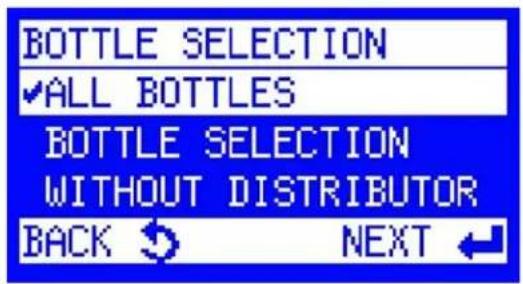


Event time: (continued)
- The Info screen is displayed.
a. If only one bottle is installed (composite sampling), select Settings Complete, and the ProSample will return to the Programs menu. Proceed to Step 12.
b. If a distributor arm and multiple bottles are installed (discrete sampling), select More Settings.
A. If you want to fill all bottles in the sampler, select All Bottles. Press the Back key once to return to the More Settings menu, then select Programming OK.
B. If you only want to fill certain bottles, select Bottle Selection.
-
First Bottle is displayed if the ProSample has more than one bottle installed. Enter the bottle number in which the first sample should be placed. Press the Enter key.
-
Last Bottle is displayed. Enter the bottle number of the last sample that should be placed. Press the Enter key.
Flow analog: (continued)

- The More Settings menu is displayed. Highlight Programming OK and press the Enter key.
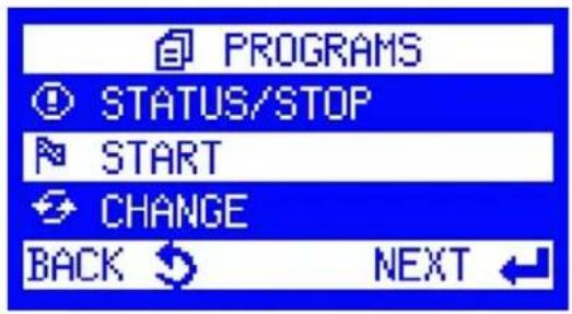
- The Programs menu is displayed. Event-based programs need to be manually started for the trigger to cause a sample to be collected. Highlight Start and press the Enter key.

- Use the arrows to select the program to run. Press the Enter key. To set the program's start and end times, Reference Section 6.3 and Section 6.4.
NOTE: Ensure the pump is calibrated before running any programs. Please see Section 4.7 Peristaltic pump calibration.
6.10 Event digital
This program requires a digital outputting device like a data logger to be connected to the sampler. Please see the Wiring section for information on how to connect this device. In this scenario, the data logger or other device will compute the flow and send a trigger pulse to the ProSample when it is time to start collecting samples. After every programmed number of pulses to the ProSample, the sampler will collect a sample.
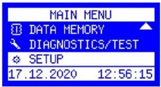
- Navigate to the main menu screen and select Programs.
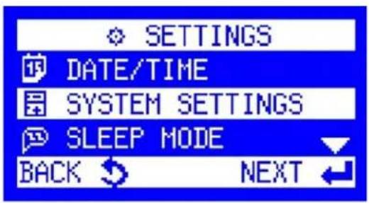
- Scroll down to Change and select Next.
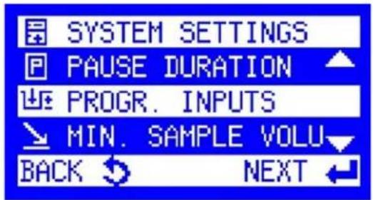
- Scroll down to Progr. Inputs and select Next.

- Select Progr. Input and select Next.
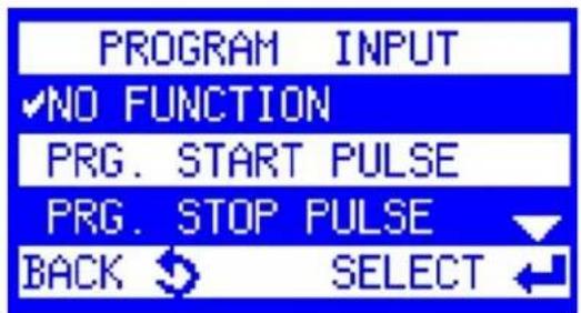

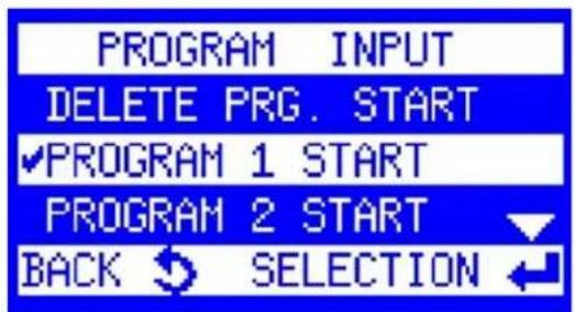


Event digital: (continued)
-
Highlight Prg. Start Pulse and press the Select.
-
Choose the Program that should start when the ProSample receives Digital Events.
-
The Program Input screen will appear. Programming the Input is completed at this point. Select the Back button four times to return to the main menu.
-
From the Main Menu screen, select Programs.
-
Scroll down to Change and select Next.
Event digital:
(continued)

- Use the left and right arrow keys to navigate to the desired program to change. Select the Next key to begin editing the program.

- Scroll down to Event Digital and select Next.
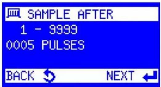
- Enter the number of trigger pulses between collected samples.

- Enter the Sample Volume that should be collected during each sample pull.

- Choose a Fill Mode.
Event digital:
(continued)
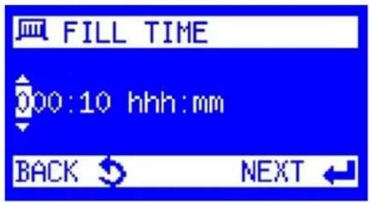


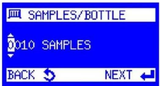

a. Time Related:
Choose how long it will take for the bottle to fill.
i. Enter the Limitation of Samples. This is the maximum amount of sample that should be collected into a single bottle. Select Next.
ii. Choose a Function that determines what will happen to a sample if there is more solution to be placed in a bottle than the bottle can hold.
Drop Samples:
Stop collecting samples and drop the extra amount.
Switch to Next Bottle:
Collect the sample in the next available bottle.
b. Sample Related:
Choose the number of samples that should fill each bottle.
For example, if 24 1L discrete bottles are used and 150 mL samples are collected, a maximum of six samples should be collected into a single bottle; otherwise, the bottle will overfill.
- The Info screen is displayed.
a. If only one bottle is installed (composite sampling), select Settings Complete, and the ProSample will return to the Programs menu. Proceed to Step 19.
Event digital:
(continued)

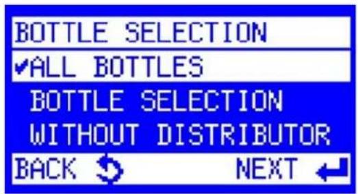

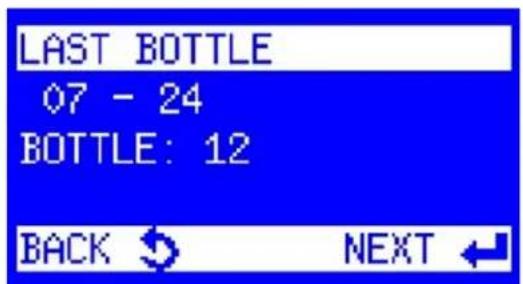
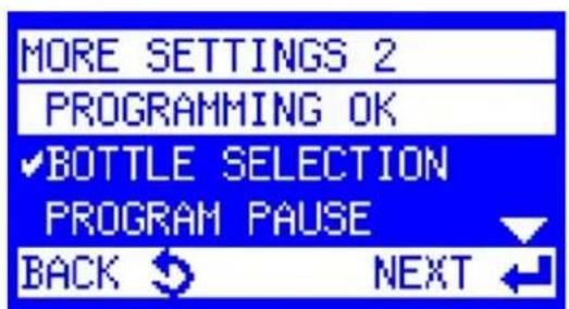
b. If there is a distributor arm and multiple bottles installed (discrete sampling), select More Settings → Bottle Selection
i. If you want to fill all bottles in the sampler, select All Bottles. Return to the More Settings menu by pressing the Back key once, then select Programming OK.
ii. If you only want to fill certain bottles, select Bottle Selection.
- First Bottle is displayed if the ProSample has more than one bottle installed. Enter the bottle number in which the first sample should be placed.
Press the Enter key.
-
Last Bottle is displayed. Enter the bottle number of the last sample that should be placed. Press the Enter key.
-
The More Settings menu is displayed. Highlight Programming OK and press the Enter key.
Event digital:
(continued)

- The Programs menu is displayed. Highlight Start and press the Enter key.

- Use the arrows to select the program to run. Press the Enter key. To set the program's start and end times, Reference Section 6.3 and Section 6.4.
NOTE: Ensure the pump is calibrated before running any programs.
Please see Section 4.7 Peristaltic pump calibration.
NOTE: The program will start when specified, but samples will not be collected until the set number of pulses is sent to the ProSample. Sampling will conclude at the user-specified time.
6.11 Event analog
This program requires a 0/4-20mA analog device to be connected to the sampler. Please see the Wiring section for information on how to connect this device. The ProSample is triggered based on certain threshold criteria from either the 4-20mA device or another device. The ProSample will then convert the analog signal into a flow, with samples collected every time the sampler passes a programmed amount of flow.
Flow data from this programming method is stored in the ProSample for viewing later in the YSI Connect software. (See Section 9 YSIConnect PC software). The program will run while the trigger threshold criteria are exceeded and turn off when the criteria are no longer met, or the bottle is filled.

- Navigate to the main menu screen and select Programs.

- Scroll down to Change and select Next.

- Use the left and right arrow keys to navigate to the desired program to change. Select the Next key to begin editing the program.

- Scroll down to Event Analog and select Next.


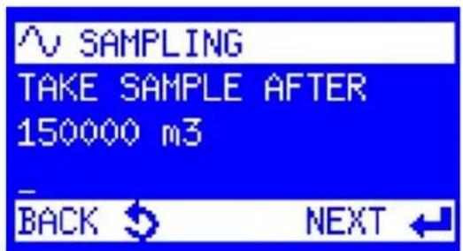


Event analog:
(continued)
- Select the Unit that the flow pacing will be measured in.
NOTE: To convert CFS to m^3/s , multiply by 0.02832.
- Set the maximum flow corresponding to the analog signal at 20 mA. The discharge rating programmed inside the ProSample is a linear equation, starting at zero flow at 0/4 mA and extending to the value corresponding to 20 mA. Select Next.
Example:
4 ~mA = 0 ~m^3 / s . 20 ~mA = 10,000 ~m^3 / s . 12 ~mA = 5,000 ~m^3 / s .
-
Set the Flow Pacing. Flow Pacing is the amount of water that passes by the ProSample between samples. Select Next.
-
The Sample Volume is displayed. This is the sample that will be collected after each aliquot of water determined in the flow pacing step has passed. The user sets the Sample Volume based on the application and sampling requirements. Press the Next key.
-
Choose the Fill Mode:
Time Related or Sample Related.
Event analog:
(continued)


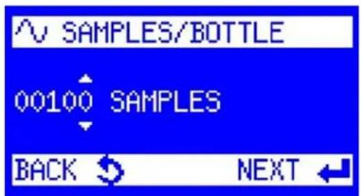

a. Time Related:
Choose how long it will take for the bottle to fill.
i. Enter the Limitation of Samples. This is the maximum amount of sample that should be collected into a single bottle. Select Next.
ii. Choose a Function that determines what will happen to a sample if there is more solution to be placed in a bottle than the bottle can hold.
Drop Samples:
Stop collecting samples and drop the extra amount.
Switch to Next Bottle:
Collect the sample in the next available bottle.
b. Sample Related:
Choose the number of samples that should fill each bottle.
For example, if 24 1L discrete bottles are used and 150 mL samples are collected, a maximum of six samples should be collected into a single bottle; otherwise, the bottle will overfill.
- The Info screen is displayed.
a. If only one bottle is installed (composite sampling), select Settings Complete, and the ProSample will return to the Programs menu. Proceed to Step 14.
b. If a distributor arm and multiple bottles are installed (discrete sampling), select More Settings.
Event analog:
(continued)


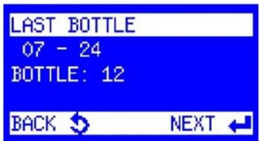
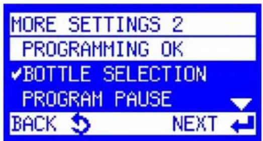
- Select Bottle Selection.
a. To fill all bottles in the sampler, select All Bottles. Press the Back key once to return to the More Settings menu, and then select Programming OK.
b. If you only want to fill certain bottles, select Bottle Selection.
-
First Bottle is displayed if the ProSample has more than one bottle installed. Enter the bottle number in which the first sample should be placed. Press the Enter key.
-
Last Bottle is displayed. Enter the bottle number of the last sample that should be placed. Press the Enter key.
-
The More Settings menu is displayed. Highlight Programming OK and press the Enter key.
Event analog:
(continued)

- The Programs menu is displayed. Event-based programs need to be manually started for the trigger to cause a sample to be collected. Highlight Start and press the Enter key.

- Use the arrows to select the program to run. Press the Enter key. To set the program's start and end times, Reference Section 6.3 and Section 6.4.
NOTE: Ensure the pump is calibrated before running any programs.
Please see Section 4.7 Peristaltic pump calibration.
NOTE: The program will start as soon as the criteria for the Event trigger are met and will continue to collect samples until the program end is reached or the Event trigger criteria are no longer met.
6.12 Variable time
This program requires a 0/4-20 mA analog device to be connected to the sampler, meaning that the Flow Signal Cable will be used. Please see the Wiring section for information on how to connect this device. The ProSample will convert the analog signal into a flow, with flow-dependent sample aliquots collected at a constant sampling interval. Flow data from this programming method is stored in the ProSample for viewing later in the YSI Connect software. (See Section 9 YSIConnect PC Software).

- Navigate to the main menu screen and select Programs.

- Scroll down to Change and select Next.

- Use the left and right arrow keys to navigate to the desired program to change. Select the Next key to begin editing the program.

- Scroll down to Variable Time and select Next.


Variable time:
(continued)
- Select the Unit that the flow pacing will be measured in.
NOTE: To convert CFS to m^3/s , multiply by 0.02832.
- Set the maximum flow corresponding to the analog signal at 20 mA. The discharge rating programmed inside the ProSample is a linear equation, starting at zero flow at 0/4 mA and extending to the value corresponding to 20 mA. Select Next.
Example:
4 ~mA = 0 ~m^3 / s . 20 ~mA = 10,000 ~m^3 / s . 12 ~mA = 5,000 ~m^3 / s .
-
Set the Sampling Interval. This is the amount of time that passes between when samples are collected. Select Next.
-
The Sample Volume at 20 mA is displayed. Input the amount of sample to be collected by the ProSample when the analog device is at 20 mA. Similarly to how flow is calculated, a regression equation is also developed for the sample volume to be collected, starting at 0 mL at 0/4 mA and extending to the value corresponding to 20 mA. Press the Next key.
Example:
4 mA = 0 mL, 20 mA = 150 mL, and 12 mA = 75 mL of sample to be collected.
- Time Related Fill Mode is selected. Select Next.
Variable time:
(continued)
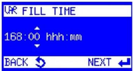
- Choose how long it will take for the bottle to fill.

- Enter the Maximum Sample Volume per bottle. Select Next.

- Choose a Function that determines what will happen to a sample if there is more solution to be placed in a bottle than the bottle can hold.

Drop Samples:
Stop collecting samples and drop the extra amount.
Switch to Next Bottle:
Collect the sample in the next available bottle.
- The Info screen is displayed.
a. If only one bottle is installed (composite sampling), select Settings Complete, and the ProSample will return to the Programs menu. Proceed to Step 17.
b. If a distributor arm and multiple bottles are installed (discrete sampling), select More Settings.
- Select Bottle Selection.
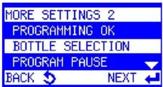
Variable time:
(continued)

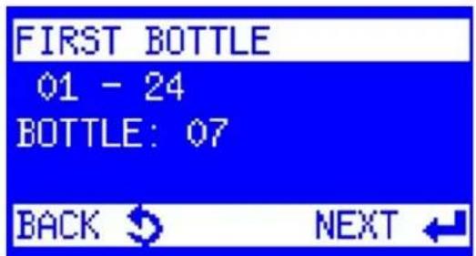
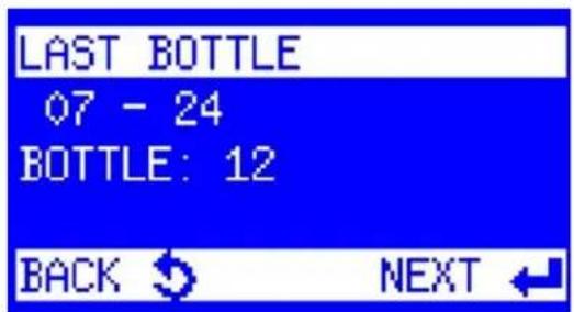


a. To fill all bottles in the sampler, select All Bottles. Press the Back key once to return to the More Settings menu, and then select Programming OK.
b. If you only want to fill certain bottles, select Bottle Selection.
-
First Bottle is displayed if the ProSample has more than one bottle installed. Enter the bottle number in which the first sample should be placed. Press the Enter key.
-
Last Bottle is displayed. Enter the bottle number of the last sample that should be placed. Press the Enter key.
-
The More Settings menu is displayed. Highlight Programming OK and press the Enter key.
-
The Programs menu is displayed. Highlight Start and press the Enter key.
Variable time:
(continued)

- Use the arrows to select the program to run. Press the Enter key. To set the program's start and end times, Reference Section 6.3 and Section 6.4.
NOTE: Ensure the pump is calibrated before running any programs. Please see Section 4.7 Peristaltic pump calibration.
6.13 Event batch sampling
This program is an "Event" based program, requiring a trigger from an external device to run. Please see the Wiring section for information on how to connect an external device. When an event triggers this program, samples will be input into a bottle based on a programmed time interval. When the trigger criteria are no longer met, sampling will cease. If the trigger criteria are met again, sampling will resume in the same bottle the sampler collected samples in during the previous event.
Example: The ProSample is equipped with 24 L bottles. The program is set to collect three 150 mL samples per bottle in 15-minute intervals for a total bottle fill time of 45 minutes. The trigger criteria are met for 30 minutes, so two samples are collected into the first bottle. The trigger criteria are met later, and the first sample from the new event will be placed into the first bottle for a total of three samples in that bottle (450 mL) before moving to the second bottle.
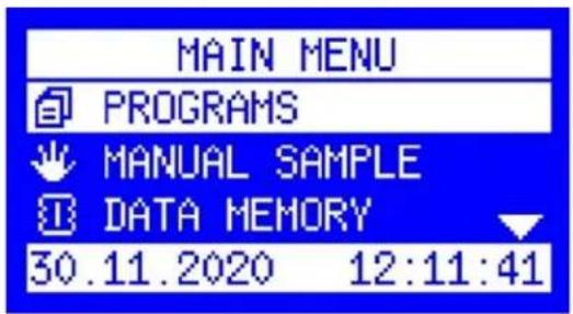

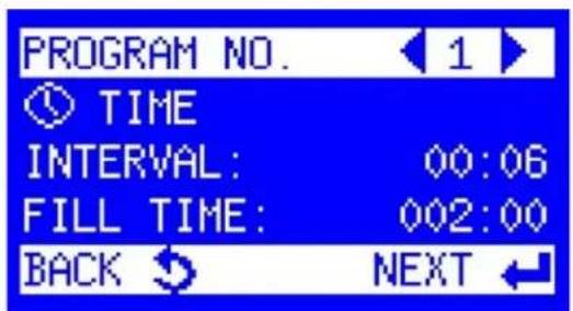
-
Navigate to the main menu screen and select Programs.
-
Scroll down to Change and select Next.
-
Use the left and right arrow keys to navigate to the desired program to change. Select the Next key to begin editing the program.
Event batch sampling:
(continued)
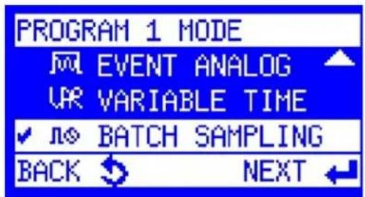
- Scroll down to Batch Sampling and select Next.
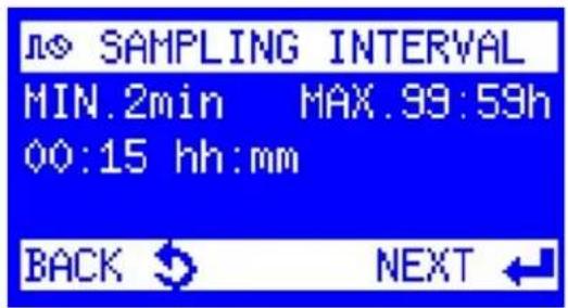
- Input the Sampling Interval. This is the amount of time that will pass between samples being collected. Select Next.

- Input the Sample Volume to be collected per sample. Select Next.

- Set the Bottle Fill Time. This is how long the bottle should be filled based on the sample volume being collected and the sample interval. A sample will be collected immediately at every Sampling Interval point.
For example, a 45-minute bottle fill time with 15-minute sampling intervals would collect four samples: one at 00:00, 00:15, 00:30, and 00:45.

- The Info screen is displayed.
a. If only one bottle is installed (composite sampling), select Settings Complete, and the ProSample will return to the Programs menu. Proceed to Step 17.
b. If a distributor arm and multiple bottles are installed (discrete sampling), select More Settings.
Event batch sampling:
(continued)

- Select Bottle Selection.
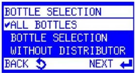
a. To fill all bottles in the sampler, select All Bottles. Press the Back key once to return to the More Settings menu, and then select Programming OK.
b. If you only want to fill certain bottles, select Bottle Selection.
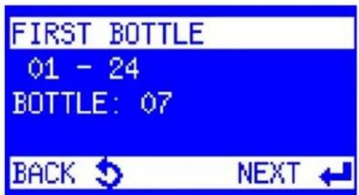
- First Bottle is displayed if the ProSample has more than one bottle installed. Enter the bottle number in which the first sample should be placed. Press the Enter key.

- Last Bottle is displayed. Enter the bottle number in which the last sample should be placed. Press the Enter key.

- The More Settings menu is displayed. Highlight Programming OK and press the Enter key.
Event batch sampling:
(continued)

- The Program menu is displayed. Highlight Start and press the Enter key.

- Use the arrows to select the program to run. Press the Enter key. To set the program's start and end times, Reference Section 6.3 and Section 6.4.
NOTE: Ensure the pump is calibrated before running any programs.
Please see Section 4.7 Peristaltic pump calibration.
NOTE: The program will start at the scheduled time, but a sample will not be collected until the trigger criteria have been met. The program will end at the user-specified time.
7. Special program functions

Advanced programming options can be found within the program settings menu:
PROGRAMS → CHANGE → TIME/FLOW/EVENT → MORE SETTINGS

7.1 Programming OK
When all the desired settings have been entered, settings are confirmed, and the display returns to the START menu.
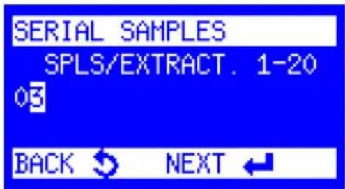
7.2 Serial samples
The number of samples per sample extraction means each requested sample extraction consists of X samples. For example, if the value 3 is entered, 3 samples are extracted successively. When activating this function, particular attention must be paid to the bottle volume to avoid overfilling. This function is useful for collecting several single samples in a very short time to obtain a bigger sample volume.

7.3 Bottle assignment
The first and last bottles of a sampling cycle can be defined. This function allows a group of bottles to be assigned to a certain program. It is recommended that you activate this function if the function "Program linkage" is used (see Section 7.7). The settings "first bottle" and "last bottle" always define the bottle group.
The bottle selection menu has no function in the ProSample PM and PM-12 as these models are for composite sampling only.
Example: In Program 1, bottles 1 up to bottle 6 are selected, and in Program 2, bottles 7 up to bottle 12 are selected. After the start of Program 1, bottles 1 – 6 are filled, and after the start of Program 2, bottles 7 – 12 are filled.

7.4 Program pause
This function is only possible if a program has been started in the "continuous operation" mode, leading to a deferred start (by the time entered) of the next program.
In other words, the pause results in a delay between the end of a program and the start of the next program.
Example: Program 1 has a program pause of 1 hour and is started at 8:00 a.m. (24-hour cycle). The program will be terminated at 8:00 a.m. the next day, and the program cycle will only be started again at 9:00 a.m. due to the entered program pause of 1 hour. Every day, the program start will be deferred by 1 hour.
7.5 QT-Automatic (Q= flow, T=time)

This feature is only available in flow-dependent programs. QT refers to time-flow automatic (minimum and/or maximum QT-TIME must be set). Minimum or maximum limits can be used separately or together.
Minimum QT-time: minimum time between two sample extractions. Use a minimum limit if there is only a weak flow signal, and thus, the sampling interval would be very long. A sample extraction is quasi-enforced to obtain at least a minimum sample volume.
Maximum QT-time: maximum time between two sample extractions. Use a maximum limit if there is a strong flow signal (e.g., due to rain) and the sample interval is very short. Sample extractions are quasi-inhibited to avoid the very quick filling of the bottles. If the bottles are filled within a very short time and there are no bottles left to be filled within the remaining runtime of the program, a maximum QT time will prevent sampling from completing too quickly.

7.6 Combined event mode
This function enables the combination of a time-dependent or flow-dependent program with an event program (e.g., in case of an exceedance of a limit value) and can be activated or deactivated. For the event program, the sampling interval and the bottle filling time must be defined in hours and minutes (hh:mm).
Program Run: As soon as an event signal occurs, the distributor arm moves to the next empty bottle (recorded in the memory as the event bottle). If the signal is present, samples are collected according to the set values. If the signal is active longer than the bottle filling time set, further bottles are filled. When the signal fades, the distributor moves to the next empty bottle and resumes the initially started sampling mode (time or flow). All this data is logged in the info memory.
7.7 Program linkage

The end of Program 1 will start Program 2, and the end of Program 2 will start Program X. In continuous operation, the last program will start Program 1 again or Program X. With this function, it is possible to link one or several programs to each other (e.g., for weekend operation with different programs per day).
Program Run:
End of Program 1 can trigger the start of Program 2. End of Program 2 can trigger the start of Program X.
The last program entered starts Program 1 again, as does any other Program X. In addition, the number of cycles can be set for each program.
7.8 Absolute start time

Using an external pulse (e.g., a palm button), a program is started at a fixed time. The program run time is determined by the bottle fill time and the number of bottles.
Example:
Number of bottles = 12; Bottle fill time = 2 hours; Start time = 8:00 a.m. Program run time = 24 hours

The program is automatically stopped after the entered run time and waits for the next external pulse. This program feature ensures that the ProSample always stays in the same time interval and uses the same bottle assignment, independently of whether the start (external pulse) is before or after the programmed start time.
- External pulse is triggered before the end of the program run time.
Example: You would like to change the bottles before the program run time expires, so you trigger an external pulse at 6:30 a.m. Therefore, the program stops at 6:30 a.m. and starts again automatically at 8:00 a.m.
- External pulse is triggered after the end of the program run time.
Example: You can only go to the sampler after the program run time has expired (e.g., 9:45 hr). When you change the bottles and trigger an external pulse, the program automatically calculates which bottle the distributor arm has to be placed at the start time, moves to that bottle, and starts sampling into this bottle.

NOTE: If Absolute Start Time is activated /deactivated, the first programmable input (PIN 40 to X5) is also automatically activated/deactivated.

7.9 Bottle Iling pause
This function enables a deferred sample extraction (filling pause) related to the bottles before the next bottle is filled.
The pause is entered in minutes between 0-10,080 (7 days).
Example:
Bottles: 24; Bottle fill time: 2 hours
Without programmed bottle filling pause:
A bottle change is made every 2 hours. After 24 hours, all 12 bottles are filled.
With programmed bottle filling pause of 24 hours (1440 minutes):
Bottle 1 is filled for 2 hours. Then, there is a bottle-filling pause of 24 hours. After 24 hours, the distributor arm changes to Bottle 2 and fills for 2 hours. There is a 24-hour delay between each bottle's filling. The whole program cycle in this example would be 12 bottles x 26 h = 312 hours (2 hours fill time + 24 hours filling pause).
As a result of this setting, each bottle is filled with a delay of 26 hours per day.
8. Maintenance and cleaning
The maintenance and cleaning steps in the sections below are pertinent to all ProSample models. Regular maintenance and cleaning is necessary for the proper performance of the sampler, with particular attention paid to all sample tubing and the peristaltic pump tube. Contact Technical Support (Section 13) for additional assistance.
NOTE: The roller assembly in the peristaltic pump is not user-replaceable.
Please contact Technical Support if you suspect an issue with the pump that may require repair.
8.1 Factory reset
A factory reset can reset all settings to the factory default. Please note that all settings and data will be deleted when a factory reset is completed. To complete a factory reset:
- Turn OFF the ProSample.
- Hold the power key and the Back key at the same time.
- When the instrument beeps, release the power key but keep the Back key pressed.
- Once the screen initializes and shows the "Load Factory Settings" page, release the Back key and allow the ProSample to boot.
8.2 Draining bottom housing
On the ProSample P and ProSample P-12, there is a drain plug in the center of the bottom sampler housing. This drain can be removed when cleaning the sampler housing, removing any spilled solution, or draining any ice used to keep collected samples cold.

8.3 Desiccant replacement
A desiccant cartridge (40% relative humidity; Item #0060589) is inside the ProSample controller to absorb moisture and prevent corrosion. Over time, the desiccant will become saturated with moisture and should be replaced.
Monitor the desiccant color through the clear plastic window. The color will change from blue to pink when the desiccant is saturated.

Desiccant replacement
8.4 Peristaltic pump tube replacement
Inspect and clean the pump tubing and rollers regularly. Replace the pump tube (Item # 0901062) when it becomes dirty or worn out. Cleaning and/or replacing the pump tube may also prove helpful if the ProSample displays an error message during a program.
YSI does not have a recommended replacement interval for the peristaltic pump tube, as the tube's lifetime varies based on application. For example, if the sampler is used at the outlet of a plant, the sampling environment is likely relatively clean with little/no solids. However, if samples are collected at the inlet, the tube may have a very short lifetime due to the amount of solids in the solution. YSI recommends always having a spare peristaltic pump tube available.
NOTE: The inside of the pump tube can be cleaned with a sponge. Cut a 12x12 mm piece of sponge and go to DIAGNOSTICS/TEST → COMPONENT TEST → PUMP. You can choose to run the pump forward (suction) and backward (purging). Moisten the sponge, hold it to the tube end, and let it "suck" through the tube. It works in both directions. Repeat until the hose is clean again.
NOTICE: Use of tubing other than that supplied by the manufacturer may cause excessive wear on mechanical parts and/or poor pump performance.
Each ProSample unit includes an extra pump tube inside the ProSample lid.
Please refer to Section 4.1.1 when replacing the peristaltic pump tube.

WARNING: Do NOT attempt to replace the peristaltic pump tube or service the pump while the ProSample is ON. The moving components of the pump can cause serious injury.
8.5 Cleaning
The ProSample should be kept clean, especially the parts exposed to the sample, such as the dosing unit, water sensors, distributor, bottles, and suction hose. Failure to do so could result in damage not covered by the warranty.
Clean the interior and exterior of the housing with a damp, lint-free cloth. If needed, use commercial household cleaners in water. Clean the unit around the distributor arm as required.
NOTICE: Do not manually rotate the distributor arm, as it can cause permanent damage to the drive. If you need to move the arm, go to DIAGNOSTICS/TEST → COMPONENT TEST → DISTRIBUTOR. Enter the Bottle position you would like the arm to move to.
In addition to the peristaltic pump tube, ensure the suction hose, distributor tube, and intermediate tube are clean. Replace if necessary.
8.6 Change fuses
If the ProSample is not operating as expected, it may be necessary to change one of the two fuses installed in the ProSample - 8 A and 2 A. To remove the fuse, rotate it as outlined in the picture below and pull it out. Insert the replacement fuse and tighten it.


8.7 Long-term storage
To prepare the ProSample for long-term storage (e.g., over the winter):
- Close all active programs.
- Purge the peristaltic pump tube, intermediate tube, and suction hose. From the Main Menu, go to DIAGNOSTICS/TEST → COMPONENT TEST → PUMP. Press the right arrow key to run the pump backward for purging. Keep the button pressed until all tubes are empty.
- Remove all liquids and, if necessary, solid matter from all tubes and bottle compartments. Clean as needed.
- Remove the peristaltic pump tube.
- Remove the battery.
- Store all items in a cool, dry place.
YSIConnect
9. YSIConnect PC software
YSIConnect is the PC software for the ProSample that allows users to download sampler data (not data collected by external devices), upload and download programs, program the sampler using the keypad and menu emulator, and synchronize time.
There are five menu screens:
- Connection
- Memory
- Programming
- Display
- Tools
The sampler is connected to a PC with the USB cable included with each ProSample.

natural_image
Line drawing of a mechanical device with an open lid and internal components, showing a close-up view of the component (no text or symbols present)USB port cover on the front of the ProSample
9.1 Connection

YSIConnect screen while disconnected
From this screen, the user can connect to the instrument via USB. To connect to an instrument, connect the USB cable from the ProSample to your computer. Click the "Connect via USB" button.
The red wrench tool icon is used to update the firmware. The Firmware Update section provides additional instructions for updating firmware. If data has been downloaded from a ProSample unit to the computer, it can be retrieved from this menu without being connected to a unit. Older data can be opened or deleted from this menu.
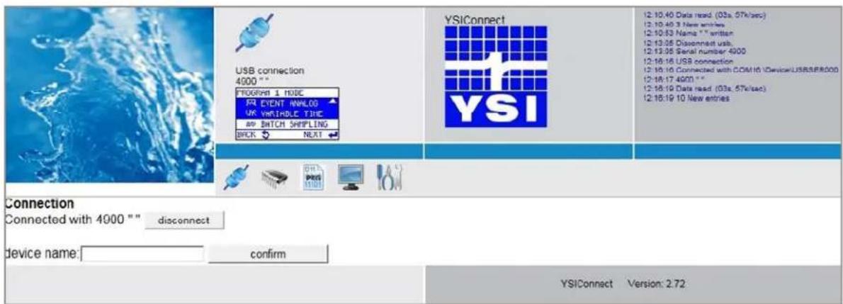
YSIConnect screen while connected to ProSample
Once connected, the Device Name can be altered from this menu. For example, a user may want to name the sampler after the location where it is deployed.
9.2 Memory
After the system is connected, all data downloaded from the device can be seen here.
There are five menus in the Memory section. The data from all of these menus can be downloaded as .xls or .csv files. If the sampler is connected to the YSICnect software, the data will periodically update or can be manually updated by clicking the refresh button.
1) Log Memory: Shows all events that happened when the sampler was powered (e.g., programmatic changes, bottle changes while sampling, errors, log messages, etc.)
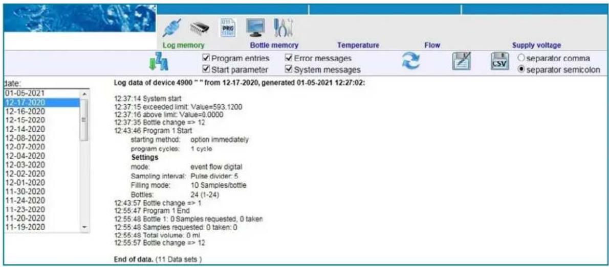
YSIConnect Log memory
2) Bottle Memory: Shows what bottles were sampled into, how many samples were requested, how many were collected, and additional sample data.
![Log memory Bottle memory Temperature Flow Supply voltage rate: 12-16-2020 16:18:56 12-16-2020 14:26:42 12-16-2020 14:25:39 12-16-2020 12:03:00 12-04-2020 12:13:49 12-04-2020 12:12:37 12-04-2020 12:06:36 12-04-2020 11:52:46 12-04-2020 11:41:39 12-03-2020 10:36:43 12-02-2020 17:17:24 12-02-2020 16:41:00 12-02-2020 15:41:12 12-02-2020 13:52:12 12-01-2020 12:32:15 12-01-2020 11:35:32 Bottle memory device 4900 "" from 12-01-2020 11:35:32, generated 01-05-2021 12:27:42: Bottle Samples Samples Start of filling Filling time Volume [ml] requested taken [Minutes] 1 5 5 01.12.2020 11:16 8 750 2 4 4 01.12.2020 11:24 9 600 3 1 1 01.12.2020 11:33 2 150](/content/2026/06/1400963/images/763d7b59fdda7fd2b72c0b3de52726e57b75b7553f744f1ac48e655afea19ea0.jpg)
YSIConnect Bottle memory
9.2 Memory, (continued)
3) Temperature: Currently, there is no data available in this menu.
4) Flow: Flow data will be shown in this menu if a flow analog program is run.

line
| Time (h) | Flow Device (m³/s) | |----------|---------------------| | 10:13 | 520.62 | | 10:23 | 821.87 | | 10:33 | 901.87 | | 10:43 | 501.25 | | 10:53 | 501.25 | | 11:03 | 500.62 |YSIConnect Flow data memory
5) Supply Voltage: Shows the battery voltage over the time period that the sampler was turned on.

line
| Time (h) | Voltage (V) | |----------|-------------| | 12-02-2020 | 13.33 | | 12-01-2020 | 13.22 | | 11-30-2020 | 13.38 | | 11-24-2020 | 13.18 | | 11-23-2020 | 13.25 | | 11-20-2020 | 13.36 | | 11-19-2020 | 13.19 | | 11-18-2020 | 13.27 | | 11-17-2020 | 13.30 | | 11-16-2020 | 13.23 | | 11-14-2020 | 13.25 | | 11-11-2020 | 13.28 | | 11-10-2020 | 13.24 | | 11-09-2020 | 13.21 | | 11-08-2020 | 13.29 | | 11-07-2020 | 13.32 | | (various values) | (various values) |YSIConnect Supply voltage memory
9.3 Programming
The Programming menu allows you to select each of the 12 program options and view the program details.
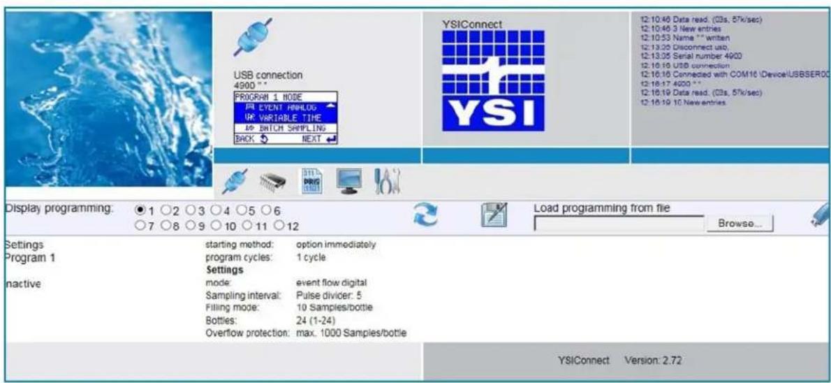
YSIConnect Programming screen
By selecting a program and clicking the Save Disk icon, a program can be saved to the local computer and uploaded to another ProSample unit later.
To load a programming file, click the Browse button next to the text field and navigate to the previously created program saved to the computer. Once selected, click the USB drive picture to load that program to the ProSample.
By clicking the refresh button, any changes to the ProSample programming will be visible.
9.4 Display
From the Display menu, a user can navigate the ProSample menus to make all changes necessary to the sampler regarding programming, configurations, triggers, etc. This menu is the exact menu that is found on the ProSample. While navigating on the computer screen, the same movements through menus can be seen on the ProSample keypad.
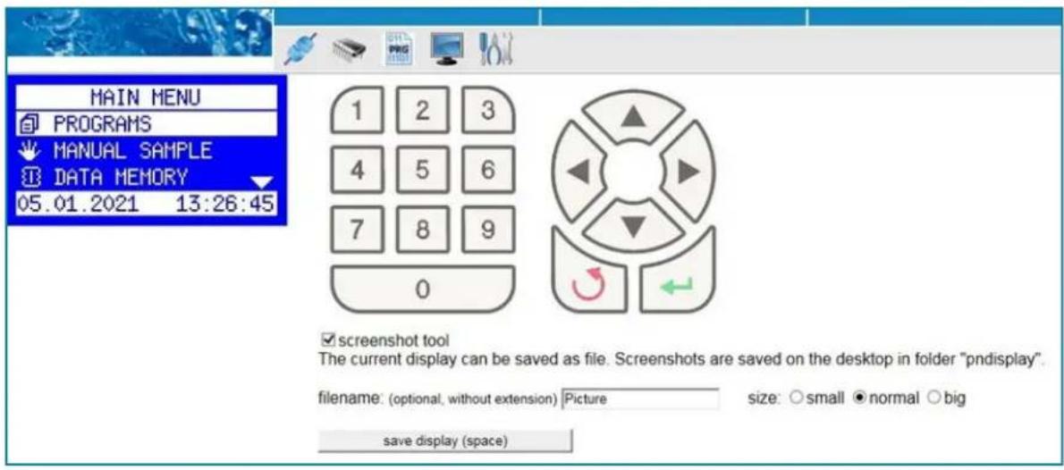
YSIConnect Keypad and display emulator
There is a Screenshot Tool available.
By clicking this button, a user can name a file and save the current keypad screen as an image.
9.5 Tools
The only function in the Tools menu is clock synchronization.
By clicking this button, the ProSample time will be set to match the computer time.
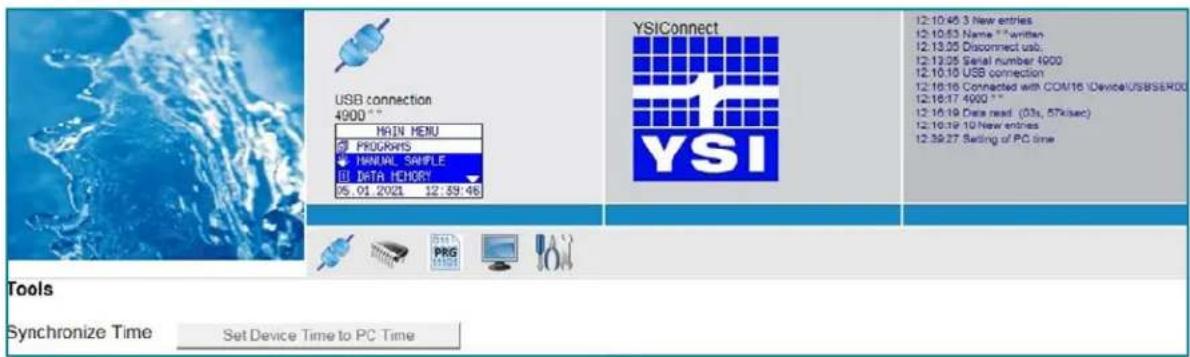
YSIConnect Tools menu
9.6 Updating the rmware
The below steps outline how to perform a firmware update on your Pro Sample unit.
- Download and install YSI Connect from the Software Downloads page at https://www.ysi.com/customer-support/software-firmware-downloads/software.
This software is used to interface with the Pro Sample units and update firmware.
a. The software will be labeled as to the right (note that the version may change since the time of this document, but the location will be the same).
b. Right-click on the downloaded folder and select Extract All.
c. Make sure you have administrator rights on your PC before opening the install application.
d. Double-click on the application in the extracted folder:
ProSample YSIConnect Software - v2.72 16 Jul 2018
YSIConnect is the PC software for the YSI ProSample. This software can be used to control the sampler, download data, and update instrument firmware.
Download YSICnect Software
[2.1 MB]
| Name | Date modified | Type | Size |
| 630116 ysiconnect 2_72 with drvr | 6/3/2019 1:38 PM | Application | 2,161 KB |
e. Follow the prompts to download the YSI Connect software.
(See step 2 on next page)
9.6 Updating the rmware, (continued)
- Download the current firmware packet using the same YSI Software Downloads Page link. It will look similar to the screenshot to the right; however, the version may look different.
a. This will be saved as a .zip file as well.
Please right-click and select Extract All on the downloaded folder.
b. Once extracted, save the folder in an easily accessible location.
The folder's name should match the .dfu file in it.
c. Below is an example of how the folder should look and what the contents should look like inside this folder.

SP5_27_Jan_29_2019_17_39_Strt_017
- Once both YSIConnect and the firmware update are downloaded/saved properly, proceed to the next step for the firmware update.
- Open up YSI Connect: (Continued on next page)
ProSample YSIConnect Software - v2.72 16 Jul 2018
YSIConnect is the PC software for the YSI ProSample. This software can be used to control the sampler, download data, and update instrument firmware.
Download YSICnect Software
[2.1 MB]
| lang_db_15 | 11/30/2018 3:12 PM | Text Doc |
| lang_db_16 | 11/30/2018 3:12 PM | Text Doc |
| lang_db_18 | 11/30/2018 3:12 PM | Text Doc |
| lang_db_19 | 11/30/2018 3:12 PM | Text Doc |
| lang_db_20 | 11/30/2018 3:12 PM | Text Doc |
| lang_db_21 | 11/30/2018 3:12 PM | Text Doc |
| lang_db_22 | 11/30/2018 3:12 PM | Text Doc |
| lang_db_23 | 11/30/2018 3:12 PM | Text Doc |
| lang_db_24 | 11/30/2018 3:12 PM | Text Doc |
| lang_db_25 | 11/30/2018 3:12 PM | Text Doc |
| MaxxLoader | 11/30/2018 3:12 PM | XML Doc |
| menu10 | 2/4/2019 5:09 PM | Text Doc |
| SP5_25_Jan_29_2019_17_39_Strt_017.dfu | 1/29/2019 4:40 PM | DFU File |
| Startwerte | 1/29/2019 4:12 PM | Text Doc |
| vcomport | 11/30/2018 3:12 PM | Setup Inf |

9.6 Updating the rmware, (continued)
- Click on the red wrench:

- If you select UP, it will go up in the directory. If you click on a folder location, it will locate the contents in that folder. If it is saved in your documents, press the Documents icon from the list, then navigate to the subfolder.
The final folder selected should be listed as shown above. In the example below, the firmware was saved in a subfolder within a Pro Sample folder:


(Continued on next page)
9.6 Updating the rmware, (continued)
- When you click on the final firmware file, it will show up briefly under update control.

- Connect your Pro Sample to your computer using a mini-USB cable. Leave the unit powered off.
- Next, press Update Control. You will then be prompted to power the unit on.

- The firmware update will now be loaded onto the unit. (Continued on next page)
NOTE: Do not touch the unit during this update or disconnect at any time. You should see screenshots like the ones on the next page during the update.
9.6 Updating the rmware, (continued)
![Software update in control unit To update the firmware in the control unit it has to be connected via USB. The folder with the firmware files has to be indicated software: SP5_25_Jan_29_2019_17_39_Strt_017 dfu directory:C:/Users/cope/Documents/Pro Sample/Firmware/SP5_27_Jan_29_2019_17_39_Strt_017 Update Phase 1 erfolgreich, Gerät startet neu. Immer noch nicht ausschalten! technical details 03.06.2019 14:53:59 update started C:/Users/cope/Documents/Pro Sample/Firmware/SP5_27_Jan_29_2019_17_39_Strt_017/SP5_24_Jan_29_2019_17_39_Strt_017.dfu 03.06.2019 14:53:55 start DfuleCommand.exe -c 03.06.2019 14:54:04 device found: Device [1]: STM Device in STU Mode, having [3] alternate targets 03.06.2019 14:54:04 start DfuleCommand.exe -c -d --fu "c:/Userc:/lope/AppDate/Roaming/ynloconnect/firmware.dfu"](/content/2026/06/1400963/images/b910a7a435bf12eda0c659df5a48cd4cf83dab78103b4e7f3daeca79b0f6fa59.jpg)
- When you see the green Update Successful, please wait for the system to reboot and power on, and for that 'Update Successful' to disappear before doing anything on the unit.
- Once you see the screen below, the update is complete, and you can disconnect the unit from your PC.
![Software update in control unit To update the firmware in the control unit it has to be connected via USB. The folder with the firmware files has to be indicated software: SP5_25_Jan_29_2019_17_39_Strt_017.dfu directory:C:/Users/lope/Documents/Pro Sample/Firmware/SP5_27_Jan_29_2019_17_39_Strt_017 name other directory C:/Users/lope/Documents/Pro Sample/Firmware/SP5_27_Jan_29_2019_17_39_Strt_017 up update control technical details 03.06.2019 14:47:51 update started C:/Users/lope/Documents/Pro Sample/Firmware/SPS_27_Jan_29_2019_17_39_Strt_017/SPS_25_Jan_29_2019_17_39_Strt_017.dfu 03.06.2019 14:47:51 start DfuSeCommand.exe -c 03.06.2019 14:48:02 device found: Device [1]: STM Device in DFU Mode, having [3] alternate targets 03.06.2019 14:48:02 start DfuSeCommand.exe -d -d --fn "C:\Users\lope\AppData\Roaming\ysiconnect\firmware.dfu" 03.06.2019 14:49:02 DfuSeCommand says: Upgrade successful ! 03.06.2019 14:49:02 device should be restarting, wait... 03.06.2019 14:49:17 answer from device COM6 \Device\USBSER000 03.06.2019 14:49:17 load 244200 Bytes C:/Users/lope/Documents/Pro Sample/Firmware/SP5_27_Jan_29_2019_17_39_Strt_017/menu10.txt 03.06.2019 14:49:17 => rec_menu 10](/content/2026/06/1400963/images/7a9257987832b979a19fffcc59196d5caecfeadee8835b71c5e277a613ba5d15.jpg)
10. Stored messages and errors
10.1 Status messages
Message Description
| PROGRAM ACTIVE When a program is started a contact is activated for the whole duration of the program | |
| PROGRAM TERMINATED Contact at a program end | |
| ERROR ACTIVE Contact in case of an error | |
| SAMPLING ACTIVE Contact at each sample extraction | |
| BOTTLE CHANGE Contact at each bottle change | |
| DISTRIBUTOR ON POS. 1 Contact when a distributor moves on position 1 | |
| MESSAGE INVERTED | Permanent contact (high). Only when there is an interruption (e.g., cable break) is a message triggered. |
| OUTPUT SIGNAL OFF Deactivation of an output signal | |
10.2 Error messages
Error # Text Description
| 1 ERROR DISTRIBUTOR A distributor is blocked, a pulse generator or a light barrier is defective. | ||
| 2 ERROR SUCTION No water, hose clogged, no vacuum (check system) | ||
| 4 ERROR LIQUID SENSOR | There is dirt in the intermediate tube in front of the sensors,or the tube is not properly installed | |
| 5 VOLTAGE LOST - END | DATE/TIME end of voltage lost | |
| 6 CHARGE STORAGE BATTERY | Battery voltage is lower than 11.15 V in idle operation | |
| 7 ERROR ANALOG SIGNAL A1 | Error message if the calibrated limit values are exceeded by 2 mAfor at least 2 min. | |
| 10 | DOOR OPEN | The door of the sample bottle compartment is not closed(only possible with the door contact option) |
| 12 | ERROR PINCH VALVE | The pinch valve does not reach the cutoff current e.g., if it is not pluggedin (only in VAR or pneumatic operation) |
| 13 | ERROR VALVE SYSTEM | The valve system does not reach the cutoff current e.g., if it is not pluggedin (only in VAR or pneumatic operation) |
| 14 | EMERGENCY CUTOFF | The current ow at an output of the controller is too high or there is a short circuit1 = error at a digital output2 = pinch valve/valve system error3 = over-current pump /distributor, hardware message4 = motor current distributor, software message5 = pump current too high, software message |
10.2 Error messages, (continued)
Error # Text Description
| 15 NO ANALOG SIGNAL The calibrated limit values of analog inputs 2-9 are exceeded by 2 mAfor x minutes (has to be ordered separately). |
| 19 POS1 NOT FOUND Bottle distribution reference position is not recognized |
| 20 ERROR BOTTLE VALVE The bottle valve reference position is not recognized |
| 21 PUMP BLOCKED The pump cannot start; clear blockages |
| 28 WATER SENSOR 1 = upper before lower sensor2 = maximum time between the sensors exceeded |
| 31 PROGRAM PARAMETERS Program System: Con guration error,The program cannot be started. (1-12) |
10.3 Log messages
Log messages about sampling events and trigger data from connected devices are stored in the ProSample memory.
NOTE: Log messages and error codes can also be accessed in YSICnect as shown in Section 9.2.
Error # Text Description
| 1 ERROR Log code 1 includes all error codes | |
| 2 PROGRAM START | Date/time as well as the number of the started program |
| 3 PROGRAM END PROG. | Date/time of the terminated program |
| 4 START PROGRAM PAUSE | Date/time of program pause start |
| 5 END OF PROGRAM PAUSE | Date/time of program pause end |
| 6 SYSTEM START | Date/time of device start or restart after a power failure |
| 9 BOTTLE CHANGE | Date/time of a bottle change |
| 10 SAMPLE EXTRACTION | Date/time of a sample extraction triggered by a program |
| 12 BTLE CHANGE REQUESTED (REMOTE) | Bottle change triggered via a programmable input(only possible if no program is active) |
| 14 VOLTAGE LOSS START | Date/time of the start of a power failure |
| 15 EVENT START | Date/time of the start of an event |
| 16 END OF EVENT | Date/time of the end of an event |
| 18 END OF SLEEP MODE | Date/time of the end of the sleep mode, only possible at portable samplers |
| 19 CONDUCTIVITYSAMPLE MEDIUM | 1st value: CV of pair of electrodes 1 when detecting water2nd value: CV after pre-purge3rd value: limit value for water detection at pneumatic module or CV for pair of electrodes 2 at VAR module |
10.3 Log messages, (continued)
Error # Text Description
| 21 BOTTLE STATISTICS | The number of samples requested and the total Number of samples taken during program run time are logged after a program has been terminated. | |
| 22 SINGLE STATISTIC Date/time as well as the number of the started program | ||
| 23 ACCESS WITH PASSWORD | Date/time of access to a menu that requires the extended password, e.g., the service menu, the stop program, the change settings, etc. | |
| 26 SPL REQUESTED (REMOTE) | Sample extraction is requested via a programmable input(only possible if no program is active) | |
| 27 SPL REQUESTED (EVENT) Sample extraction triggered via an event program | ||
| 28 ANALOG VALUE A1 | mA signal values(logging interval can be set in SYSTEM SETTINGS → LOGENTRIES)(log of current value, no average value calculation)1st value: measured value at logging time2nd value: lower limit value3rd value: upper limit value | |
| 29 ANALOG VALUE X | mA signal values. Logging interval: each x-minutes.1st value: No. of channel2nd value: average value of logging interval3rd value: upper limit value (has to be ordered separately by the customer) | |
| 30 | OVERFILL PROTECTION1 = Drop sample2 = Switch to next bottle | The over ll protection function has been activated in ow-dependent sampling mode1st value: the requested sample was dropped2nd value: the requested sample was lled into the next bottle |
| 31 SAMPLING SUPPRESSED | only with active Q/T-function!Samples are suppressed when the ow is too HIGH | |
| 32 SAMPLING ENFORCE | only with active Q/T-function!Samples are enforced when the ow is too LOW | |
| 35 TOTAL VOLUME | At the program stop the total volume of all samples requested during the program run is added up (only at VAR and peristaltic pump systems) | |
| 36 FLOW WHEN SAMPLING | Logging of ow at the time a sample extraction has been triggered(only at VAR and peristaltic pump systems) | |
| 37 RWA-DWA STATUS | Values are logged when the rain weather pulse divider is activated or deactivated. Selection is made per weekday from 00:00 – 23:59.(Only available at the Limburg sampler version) | |
11. Replacement parts and accessories
Ordering
Telephone: +1 800.897.4151 (USA), +1 937.767.2762 (Globally)
Monday through Friday, 8:00 AM to 5:00 PM ET
Fax: +1 937.767.9353 (orders)
Email: ysi.info@xylem.com
Mail: YSI Incorporated, 1725 Brannum Lane Yellow Springs, OH, 45387 USA
Website: ysi.com
When placing an order please have the following available:
- YSI account number (if available)
- Name and phone number
- Purchase Order or Credit Card number
- Model Number or brief description
- Billing and shipping addresses
- Quantity
NOTE: The roller assembly in the peristaltic pump is not user-replaceable.
Please contact Technical Support if you suspect an issue with the pump that may require repair.
ProSample portable automatic samplers
YSI Item # Description Notes
| 630141 | ProSample P portable sampler with plastic housing, peristaltic pump, microprocessor control, battery operated 12 V/7.5 Ah. Includes battery, two peristaltic pump tubes, USB cable, Getting Started Guide, and a 5 meter suction hose with screw connection and sinker weight. | Battery charger not included, optional sample bottle sets with distributor arm sold separately |
| 630111 | ProSample P-12 portable sampler with plastic housing, peristaltic pump, microprocessor control, battery operated 12 V/7.5 Ah, and SDI-12 connectivity. Includes battery, two peristaltic pump tubes, USB cable, Getting Started Guide, and a 5 meter suction hose with screw connection and sinker weight. | Battery charger not included, optional sample bottle sets with distributor arm sold separately |
| 630140 | ProSample PM mini portable sampler with plastic housing, peristaltic pump, microprocessor control, battery operated 12 V/7.5 Ah. Includes 10 L PE composite sampling bottle with lid, battery, two peristaltic pump tubes, USB cable, Getting Started Guide, and a 5 meter suction hose with screw connection and sinker weight. | Battery charger not included |
| 630110 | ProSample PM-12 mini portable sampler with plastic housing, peristaltic pump, microprocessor control, battery operated 12 V/7.5 Ah, and SDI-12 connectivity. Includes 10 L PE composite sampling bottle with lid, battery, two peristaltic pump tubes, USB cable, Getting Started Guide, and a 5 meter suction hose with screw connection and sinker weight. | Battery charger not included |
Sample bottles and distributor arm for ProSample P and ProSample P-12
YSI Item # Description Used with
| 630134 Set of (24) 1 L bottles (PE) with lids ProSample P and ProSample P-12 | ||
| 630135 Set of (8) 2 L bottles (PE) with lids and fixing plate | " | |
| 630136 Set of (4) 4 L bottles (PE) with lids and fixing plate | " | |
| 630152 Set of (24) 350 mL bottles (glass) with lids and fixing plate | " | |
| 630142 Set of (12) 1 L bottles (glass) with lids and fixing plate | " | |
| 630143 Set of (8) 2 L bottles (glass) with lids and fixing plate | " | |
| 630118 26 L (PE) composite bottle with lid | " | |
| 630112 | Distributor arm for 24 x 1 L PE, 8 x 2 L glass, 12 x 950 mL glass, 24 x 350 mL glass; distributor tube (0901064) is pre-installed | Bottle sets 630134, 630143, 630142, and 630152 |
| 630113 | Distributor arm for 4 x 4 L PE and 8 x 2 L PE; distributor tube (0901064) is pre-installed | Bottle sets 630135 and 630136 |
Flow signal and SDI-12 cables
YSI Item # Description Used with
| 630147 | 10 meter flow signal cable with open cable end for wiring to a digital or analog device, as well as non-SDI-12 event connections (i.e. a relay) | All ProSample models |
| 630146 | 10 meter SDI-12 cable with open cable end for wiring to an SDI-12 device (e.g. EXO1 and EXO2 with signal output adapter) | ProSample P-12 and ProSample PM-12 |
| 630145-10 | 10 meter SDI-12 cable with 6-pin female wet-mate connector for direct connection to YSI EXO3 sonde | " |
| 630145-33 | 33 meter SDI-12 cable with 6-pin female wet-mate connector for direct connection to YSI EXO3 sonde | " |
| 630155 | Cable for connection of ProSample to external 12 V DC source, 2.5 m length | All ProSample models |
Battery chargers
YSI Item # Description Used with
| 630137 | Battery charger, IP-67 (waterproof) rated, for US customers, CEC compliant | All ProSample models |
| 630122 | Battery charger, IP-67 (waterproof) rated, for non-US customers, does not include international adapters | " |
| 630153 International adapter kit 630122 charger | ||
Accessories
YSI Item # Description Used with Notes
| 0030051 Strainer 8 x 8 mm | All ProSample models | ||
| 0901025 Strainer 2 x 2 mm | " | ||
| 0069810 | Y-Cable for continuous connection of the ProSample battery to AC power.Only recommended if AC power source near location of ProSample. This allows the battery to receive continuous charge. | " | Only recommended if there is an AC power source near the location of the ProSample. This allows the ProSample to always be connected to AC power. |
| 0901074 Lockable latches - Qty of 4 | " | ||
| 0901072 | Suspension harness for ProSample PM and ProSample PM-12 | ProSample P and ProSample P-12 | |
| 0901073 | Suspension harness for ProSample P and ProSample P-12 | " | |
| 0900045 Suspension Bar for harness | All ProSample models and suspension harnesses | Ideal for use in sewers | |
| 0901097 Transport Trolley | ProSample P and ProSample P-12 | ||
Replacement parts
YSI Item # Description Used with Notes
| 630132-05 | 5 meter suction hose with screw connection and sinker weight | All ProSample models | Included with all ProSample models |
| 630132-10 | 10 meter suction hose with screw connection and sinker weight | " | |
| 630132-20 | 20 meter suction hose with screw connection and sinker weight | " | |
| 630125 | SDI-12 connector to ProSample, no cable included | P-12 and PM-12 | Same as 630146 but without the cable |
| 0050598 | Stainless steel sinker weight, length 180 mm | All ProSample models | Pre-installed in all YSI suction hoses |
| 0069793 | USB cable - USB2.0 to USB Mini " | Included with all ProSample models | |
| 0901055 | Battery pack, 7.5 Ah with connection cable and fuse holder | " " | |
| 0060589 | Desiccant cartridge " | Replace the desiccant cartridge installed inside the ProSample controller when it changes from blue to pink. | |
| 630119 | Fuse T 8A 5x20 " | There are two fuses installed in the ProSample. Please refer to the Changing the fuse(s) section to ensure the correct replacement fuse is ordered. | |
| 630120 | Fuse 2A " | There are two fuses installed in the ProSample. Please refer to the Changing the fuse(s) section to ensure the correct replacement fuse is ordered. | |
| 0901101 | Battery retaining band " | Replacement for the retaining band already installed on all ProSample units. | |
| 0901062 | Peristaltic pump tube " | An extra tube is supplied with each ProSample. Replace the pump tube when it has become dirty or worn out. | |
| 0901063 | Intermediate tube; does not include the 630126 adapter that allows connection of the suction hose | " | This tube is located between the sensors on the peristaltic pump. |
Replacement parts, (continued)
YSI Item # Description Used with Notes
| 0901064 Distributor tube | All ProSample models | Pre-installed in the 630112 and 630113 distributor arms; connects to the peristaltic pump; for the ProSample PM and ProSample PM-12, this tube can be used as a replacement composite tube, although the user may want to cut it to the appropriate length. | |
| 630126 | Adapter, male 3/4 inch-14BSPP to barbed 10 mm ID; this adapter is installed at the end of intermediate tube and allows for connection of the intermediate tube to the suction hose | " | This adapter is pre-installed in the intermediate tube included with each ProSample unit but it is NOT included with the replacement intermediate tube (0901063). |
| 630127 | Adapter, female 3/4 inch-14BSPP to barbed 3/8 inch ID; this adapter is installed at the end of the suction hose and allows for connection of the suction hose to the intermediate tube | " | This adapter is pre-installed in each suction hose. This adapter is helpful if the adapter on the suction hose breaks or if using a suction hose that is not sold by YSI. |
| 0050695-VA Tube connector V2A (stainless steel); 1 piece " | There are two tube connectors located on the outside of the pump housing. ProSample units ship with the V2A connectors. | ||
| 0050695-PTFE | Tube connector PTFE; 1 piece " | There are two tube connectors located on the outside of the pump housing. ProSample units ship with the V2A connectors. | |
| 0060584 Replacement bottle, 1 L, PE | |||
| 630150 Replacement cap for 1 L bottle | |||
| 0060636 Replacement bottle, 2 L, PE | |||
| 0060634 Replacement bottle, 4 L, PE | |||
| 0030052 Replacement bottle, 350 mL, Glass | |||
| 0060628 Replacement cap for 350 mL bottle, PE white | |||
| 0030054 Replacement bottle, 950 mL, Glass | |||
| 0060640 Replacement cap for 950 mL bottle, PE white | |||
| 0030013 Replacement bottle for 2 L, Glass | |||
| 0060161 Replacement cap for 2 L, PE white | |||
| 630151 Replacement 10 L (PE) bottle with lid | |||
Warranty, technical support, and service info
12. Warranty and Liability
The manufacturer warrants that the product supplied is free of material and manufacturing defects and undertakes the obligation to repair or replace any defective parts at zero cost.
The warranty period is 12 months from the date of shipment. Consumables and damage caused by improper handling, poor installation, or incorrect use are excluded from this warranty.
With the exclusion of further claims, the supplier is liable for defects including the lack of assured properties as follows: all those parts that, within the warranty period calculated from the day of the transfer of risk, can be demonstrated to have become unusable or that can only be used with significant limitations due to a situation present prior to the transfer of risk, in particular due to incorrect design, poor materials or inadequate nish will be improved or replaced, at the supplier's discretion. The identification of such defects must be noticed to the supplier in writing without delay, however at the latest 7 days after the identification of the fault. If the customer fails to notify the supplier, the product is considered approved despite the defect. Further liability for any direct or indirect damages is not accepted.
If instrument-specific maintenance and servicing work de-ned by the supplier is to be performed within the warranty period by the customer (maintenance) or by the supplier (servicing) and these requirements are not met, claims for damages due to the failure to comply with the requirements are rendered void.
Any further claims, in particular claims for consequential damages, cannot be made.
Consumables and damage caused by improper handling, poor installation, or incorrect use are excluded from this warranty.
13. Technical support
Telephone: +1 800.897.4151 (USA), +1 937.767.2762 (Globally)
Monday through Friday, 8:00 AM to 5:00 PM ET
Email: ysi.info@xylem.com
ysi.com/ProSample

Scan for ProSample tutorial videos
14. Service information
When returning the ProSample for service, include the YSI Product Return Form with cleaning certification.
The form must be Iled out for the YSI Service Center to accept the instrument for service.
NOTE: When sending a ProSample to YSI for service, please include the battery.
Xylem l'zīləml
1) the tissue in plants that brings water and nutrients upward from the roots.
2) a leading global water solutions company.
Xylem is the connective tissue and system in plants which cleanses and transports water from the root to where it is needed most to sustain life.
And this is the essence of Xylem as a company. We are committed to driving sustainable impact by ensuring our connected technologies and solutions support our customers and the communities they serve, to tackle the water challenges that matter most to them.
For more information on how Xylem can help you, visit xylem.com.
Learn more: ysi.com/ProSample

xylem
YSI Incorporated
1725 Brannum Lane
Yellow Springs, OH 45387
+1 937.767.7241 (US)
ysi.info@xylem.com
ysi.com
- YSI ProSample
- ProSample instrument safety information
- Please read this entire manual before unpacking, setting up, or operating this equipment.
- Precautionary symbols in the manual
- Precautionary symbols on the instrument
- This is an interactive document
- Table of contents
- Safety information.... 2
- Introduction ...... 6
- Power options ...... 12
- Installation 19
- Instrument setup and calibration 23
- Contents
- Connecting analog, digital I/O, and SDI-12 devices 35
- Sampling program 49
- Special program functions ...... 91
- Maintenance and cleaning.... 95
- YSIConnect PC software 99
- Stored messages and errors....110
- Replacement parts and accessories....113
- Introduction
- Intended use and overview
- All ProSample models have the following features:
- Keypad overview
- LED functionality
- Package contents
- Unpacking
- Technical specifications
- ProSample specifications
- Dimensions
- Power options
- Battery
- Battery life and capacity
- Charging and installing the battery
- To install the battery:
- Subsequent battery charges
- Enabling sleep mode
- To enable sleep mode:
- External power options
- Connect the battery to mains power
- For continuous connection of the battery to AC power via the Y-cable:
- External battery
- To connect the ProSample to an external battery:
- Installation
- Choosing a sampling site
- Suction hose connection, positioning, and length
- The suction hose cannot be longer than 30 meters.
- Harness applications
- Suspension harnesses
- Instrument setup and calibration
- Installing the tubing
- Peristaltic pump tube
- Intermediate tube
- To install the intermediate tube:
- Turning the ProSample on
- Sample bottle installation
- Remove the top of the housing
- Prepare sample bottles and install
- Reattach the top of the housing
- Distributor arm installation
- To install a distributor arm:
- Con gure key instrument settings
- Setup → System Settings → Pre purge
- Setup → System Settings → Post purge
- Setup → System Settings → Rinse Before Sampl.
- Water sensor calibration
- To perform the water sensor calibration:
- Peristaltic pump volume calibration
- Calibration containers
- Calibration procedure
- The following steps describe how to calibrate the ProSample peristaltic pump:
- Calibration check
- To complete a calibration check:
- After calibration and/or calibration check
- Connecting analog, digital I/O, and SDI-12 devices
- Flow signal cable wiring
- Flow signal wire colors
- Calibrating the analog signal
- To calibrate the analog signal:
- SDI-12 cable wiring
- SDI-12 cable with ying leads
- SDI-12 cable with EXO3 connector
- Triggering a program
- Analog input trigger
- Trigger setup
- Trigger setup:
- Trigger setup: (continued)
- (continued)
- Digital input trigger
- SDI-12 Input trigger
- Sampling programs
- Sampling scenario list and descriptions
- Main menu tree
- Program start options
- Program end options
- Program status
- Status/Stop
- Info:
- Pause:
- Stop:
- Time-paced
- Flow digital
- Flow digital:
- Drop Samples:
- Switch to Next Bottle:
- b. Sample Related:
- Flow digital: (continued)
- Flow analog
- Flow analog: (continued)
- Flow analog:
- Event time
- Event time: (continued)
- Event digital
- Event digital: (continued)
- Event digital:
- Event analog
- Event analog:
- Example:
- Variable time
- Variable time:
- Event batch sampling
- Event batch sampling:
- Special program functions
- Programming OK
- Serial samples
- Bottle assignment
- Program pause
- QT-Automatic (Q= flow, T=time)
- Combined event mode
- Program linkage
- Program Run:
- Absolute start time
- Bottle Iling pause
- Maintenance and cleaning
- Factory reset
- Draining bottom housing
- Desiccant replacement
- Peristaltic pump tube replacement
- Cleaning
- Change fuses
- Long-term storage
- YSIConnect
- YSIConnect PC software
- There are five menu screens:
- Connection
- Memory
- Memory, (continued)
- Programming
- Display
- Tools
- Updating the rmware
- ProSample YSIConnect Software - v2.72 16 Jul 2018
- Updating the rmware, (continued)
- Stored messages and errors
- Status messages
- Error messages
- Error messages, (continued)
- Log messages
- Log messages, (continued)
- Replacement parts and accessories
- Ordering
- When placing an order please have the following available:
- ProSample portable automatic samplers
- Sample bottles and distributor arm for ProSample P and ProSample P-12
- Flow signal and SDI-12 cables
- Replacement parts, (continued)
- Warranty and Liability
- Technical support
- Service information
- Xylem l'zīləml
Brand : YSI
Model : ProSample
Category : Measuring equipment