VISIX V - Surveillance Camera 3xLOGIC - Free user manual and instructions
Find the device manual for free VISIX V 3xLOGIC in PDF.


| Product Type | Surveillance Camera |
| Brand | 3xLOGIC |
| Model | VISIX V |
| Image Sensor | 1/2.8" Progressive Scan CMOS |
| Resolution | 5 Megapixels (2592 x 1944) |
| Lens | 2.8-12mm varifocal motorized lens |
| Field of View | Horizontal: 90°-30°, Vertical: 65°-22° |
| Night Vision | Up to 30m with IR LEDs |
| Storage | MicroSD card slot up to 128GB |
| Power Supply | PoE (Power over Ethernet) 802.3af or DC 12V |
| Power Consumption | Max 7.5W |
| Dimensions (with mount) | 200mm x 100mm x 90mm |
| Weight | Approx. 1.2 kg |
| Operating Temperature | -30°C to 60°C (-22°F to 140°F) |
| Connectivity | 100Base-TX Ethernet, Wi-Fi optional |
| Mounting Type | Wall or ceiling mount included |
| Weather Rating | IP66 (outdoor rated) |
| Motion Detection | Built-in PIR sensor and video analytics |
| Audio | Built-in microphone and speaker |
| Software Compatibility | 3xLOGIC VMS (Video Management System) |
| Warranty | 2 years limited warranty |
Frequently Asked Questions - VISIX V 3xLOGIC
User questions about VISIX V 3xLOGIC
0 question about this device. Answer the ones you know or ask your own.
Ask a new question about this device
Download the instructions for your Surveillance Camera in PDF format for free! Find your manual VISIX V - 3xLOGIC and take your electronic device back in hand. On this page are published all the documents necessary for the use of your device. VISIX V by 3xLOGIC.
USER MANUAL VISIX V 3xLOGIC
natural_image
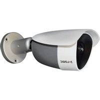
White 3x LOGIC security camera with mounted lens and mounting bracket (no visible text or symbols on body)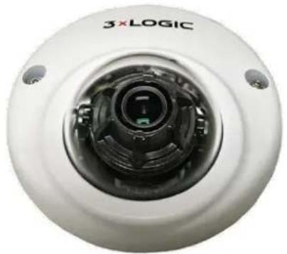
natural_image
Close-up of a white spherical device with a central lens and two ports, labeled '3xLOGIC' (no additional text or symbols visible)
natural_image
Close-up of a 3x LOGIC security camera with visible lens and control buttons (no text or symbols on body)
natural_image
Exterior view of a 3x LOGIC security camera (no text or symbols on body)VISIX V-Series All-in-One Cameras
User Manual
VIGIL v8.8 All-In-One Soware
This manual applies to the following camera models:
| Camera Type | Model |
| 2 Megapixel Exterior Bullet Camera | VX-2A-B-IWD |
| 2 Megapixel Exterior Bullet Camera w/Remote Focus | VX-2A-B-RIWD |
| 2 Megapixel Exterior Dome Camera | VX-2AD3-IWD |
| 2 Megapixel Interior Mini Dome Camera | VX-2A-IMD-X |
| VERA 36° Field-of-Vision Thermal Bullet Camera | VX-VT-36 |
Thank you for purchasing our product. If there are any quesons, or requests, please do not hesitate to contact your sales representave or a 3xLOGIC support representave.
This manual may contain technical inaccuracies or prinng errors. Examples are based on VIGIL
Soware Version 8.80.0008 running over rmware 1.10.7.3. The camera's UI appearance may appear dierently depending on your current VIGIL soware and camera rmware versions.
The content of this guide is subject to change without noce. The manual will be amended if there are any hardware updates or changes.
Regulatory Informaon
FCC Informaon
FCC compliance: This equipment has been tested and found to comply with the limits for a digital device, pursuant to part 15 of the FCC Rules. These limits are designed to provide reasonable protecon against harmful interference when the equipment is operated in a commercial environment. This equipment generates, uses, and can radiate radio frequency energy and, if not installed and used in accordance with the instrucon manual, may cause harmful interference to radio communicaons. Operaon of this equipment in a residential area is likely to cause harmful interference in which case the user will be required to correct the interference at his own expense.
FCC Conditions
This device complies with part 15 of the FCC Rules. Operaon is subject to the following two conditions:
1). This device may not cause harmful interference.
2). This device must accept any interference received, including interference that may cause undesired operaon.
EU Conformity Statement

This product and - if applicable - the supplied accessories too are marked with "CE" and comply therefore with the applicable harmonized European standards listed under the Low Voltage Direcve 2006/95/EC, the EMC Direcve 2004/108/EC, the RoHS Direcve 2011/65/EU.

2012/19/EU (WEEE direcve): Products marked with this symbol cannot be disposed of as unsorted municipal waste in the European Union. For proper recycling, return this product to your local supplier upon the purchase of equivalent new equipment, or dispose of it at designated collecon points. For more informaon see: www.recyclethis.info.


2006/66/EC (baery direcve): This product contains a baery that cannot be disposed of as unsorted municipal waste in the European Union. See the product documentaon for specic baery informaon. The baery is marked with this symbol, which may include leering to indicate cadmium (Cd), lead (Pb), or mercury (Hg). For proper recycling, return the baery to your supplier or to a designated collecon point. For more informaon see: www.recyclethis.info
Safety Instrucon
These instrucons are intended to ensure that the user can use the product correctly to avoid danger or property loss.
The precauon measure is divided into 'Warnings' and 'Cauons':
WARNING: Serious injury or death may be caused if any of these warnings are neglected.
CAUTION: Injury or equipment damage may be caused if any of these cauons are neglected.
WARNING:
Please adopt a power adapter which can meet the safety extra low voltage (SELV) standard when possible, and source with 12 VDC or 24 VAC (depending on models) according to the IEC60950-1 and Limited Power Source standard. Before applying power to the camera, check the power source to ensure that it is within the speciaons
If the product does not work properly, please contact your dealer or the nearest service center. Never aempt to disassemble the camera yourself. (We shall not assume any responsibility for problems caused by unauthorized repair or maintenance.)
To reduce the risk of re or electrical shock, do not expose this product to rain or moisture unless it is an exterior/weatherproof model. Please do not install the camera in a place exposed to direct sunlight. Do not operate the camera in environments beyond the specied temperature. Refer to the VISIX V-Series All-in-One Hardware and Installaon manual for environmental conditions and limitaons of your parcular camera model.
This installaon should be made by a qualified service person and should conform to all the local codes.
■ Please install blackout equipment into the power supply circuit to prevent footage and data loss.
- Please make sure that the ceiling can support more than 50(N) Newtons of gravity if the camera is xed to the ceiling.
CAUTION:
■ Make sure the power supply voltage is correct before using the camera.
■ Do not drop the camera or subject it to physical shock.
- Do not touch sensor modules with ngers. If cleaning is necessary, use a clean cloth with a bit of ethanol and wipe it gently. If the camera will not be used for an extended period of me, put on the lens cap to protect the sensor from dirt.
- Do not aim the camera lens at the strong light such as sun or incandescent lamp. The strong light can cause fatal damage to the camera.
The sensor may be burned out by a laser beam, so when any laser equipment is being used, make sure that the surface of the sensor not be exposed to the laser beam.
Do not place the camera in extremely hot, cold temperatures (the operang temperature should be between -30^ 60^ , or -40^ 60^ if the camera model has an “H” in its sux), dusty or damp environment, and do not expose it to high electromagnec radiaon.
■ To avoid heat accumulaon, good venlaon is required for a proper operang environment.
- Keep the camera away from water and any liquid.
■ While shipping, the camera should be packed in its original packing. - Improper use or replacement of the baery may result in hazard of explosion. Please use the manufacturer recommended baery type.
NOTE:
For cameras that support IR, you are required to pay aenon to the following precautions to prevent IR reecon.
Dust or grease on the dome cover will cause IR reection. Please do not remove the dome cover Im unl the installaon is nished. If there is dust or grease on the dome cover, clean the dome cover with clean so cloth and isopropyl alcohol.
■ Make certain the installaon locaon does not have reece surfaces of objects too close to the camera. The IR light from the camera may react back into the lens causing reecon.
The foam ring around the lens must be seated ush against the inner surface of the bubble to isolate the lens from the IR LEDs. Fasten the dome cover to camera body so that the foam ring and the dome cover are aached seamlessly.
Table of Contents
1 VISIX V-SERIES ALL-IN-ONE CAMERAS .... 10
1.1 INTRODUCTION 10
2 IDENTIFYING THE CAMERA ON YOUR NETWORK....11
2.1 IDENTIFYING CAMERA IP ADDRESS....11
Manually Identify Camera IP Address (MAC Address HEX Conversion) 11
Automacally Idenfy Camera IP Address with 3xLOGIC Camera Setup Utility ....12
Video Preview Using the 3xLOGIC Camera Setup Utility....13
3 ACCESSING THE CAMERA BROWSER INTERFACE....14
3.1 LOGGING IN TO THE CAMERA....14
AcveX Installaon 14
4 QUICK START....15
4.1 VIEW LIVE AND PLAYBACK (RECORDED) VIDEO....15
Viewing Live Video 15
Viewing Playback Video....16
4.2 CONFIGURE VIGIL CONNECT ALIAS....18
4.3 CONFIGURE A VIDEO ANALYTICS (VCA) RULE (ANALYTICS LICENSE REQUIRED) 19
Enabling VCA....19
VCA Analycs Calibraon 19
VCA Analycs Rule Conguraon 21
Conguring a Line (Tripwire) with On-Screen Counter 21
Conguring a Dwell Timer Zone 23
Previewing Analycs Overlay....23
4.4 INTEGRATING ALL-IN-ONE CAMERA WITH VIGIL SERVER USING VIGIL ANALYTICS BRIDGE 25
Installaon of Analycs Bridge 25
VIGIL Server Conguraon....26
VIGIL Server Conguraon – Network Camera Sengs 27
VIGIL Analycs Bridge – Launching the VIGIL Analycs Bridge 28
Conguring a 3xLOGIC All-in-One Camera in the VIGIL Analycs Bridge....29
4.5 ADDING ALL-IN-ONE CAMERA TO VIGIL SUITE UTILITIES 32
VIGIL Client - Adding a V-Series All-in-One Camera 32
VIGIL VCM - Adding a V-Series All-in-One Camera....33
3xLOGIC View Lite II Mobile (Android and iOS) – Adding a V-Series All-in-One Camera......34
3xCLOUD Cross-Platform Web Client – Adding a V-Series All-in-One Camera.... 35
4.6 REBOOT AND RESET TO FACTORY DEFAULT PROCEDURES 36
Reboong the Camera using the reset buon....36
Reboot the Camera Using the 3xLOGIC Camera Setup Utility 36
Reboot the Camera via Web Browser Interface 36
Reseng Camera Sengs to Factory Default 36
Reset to Factory Default Sengs via camera Web interface 37
5 BASIC TAB....38
Recording Device Control 45
6 LIVE AND SEARCH (PLAYBACK) TABS 46
6.1 LIVE TAB....46
Live Viewer – Opons Panel – Opons Tab....46
Live Viewer – Opons Panel – Status Tab 48
6.2 SEARCH (PLAYBACK) TAB 48
7 SETUP (ADVANCED) TAB....51
7.1 BASIC CONFIGURATION MENU....51
Users 51
Add a User....51
Modify a User....52
Remove a User 52
User Authencaon 52
TCP/IP 52
Basic Conguraon Menu - TCP/IP Sengs - IPv6 Sengs Conguraon....53
Date & Time 54
Stream....55
Stream Seings....56
Snapshot Sengs 56
Focus Assist....57
7.2 VIDEO MENU....57
Camera....57
General Sengs....58
Video Appearance Sengs 58
Video Transform Seings....58
Exposure Sengs....59
Digital Wide Dynamic Range Sengs 60
Day & Night Sengs....60
White Balance Sengs....61
Image Signal Processing Sengs....61
Video Stabilizaon Sengs 61
Burnt-In Text (OSD) 62
Encoder Prole 63
Adding or Modifying an Encoder Prole 63
Stream....64
Stream Seings....65
Privacy Mask....66
Video Out (BNC) 66
7.3 EVENT CONFIGURATION MENU....67
Event rules 67
Adding or Modifying an Event Rule 68
Event Source (Triggers) Tab - Adding/Modifying Event Rule 69
Event Acon Tab - Adding/Modifying Event Rule 70
Moon Detecon....71
Face Detecon 72
Network Loss....73
Heart Beat....74
Schedule....74
Adding/Modifying a Schedule 75
E-Mail Recipients 75
Add/Modify an E-Mail Recipient....76
FTP Nocaon 77
Add/Modify an FTP Server 78
HTTP Nocaons 79
Add/Modify an HTTP Server 80
TCP Nocaons....81
TCP Server 82
Mulcast Nocaon 83
7.4 NETWORK CONFIGURATION MENU....84
TCP/IP Seng 84
Network Conguraon Menu - TCP/IP Sengs - IPv6 Seings Conguraon 85
Web Server Sengs....86
NTP Sengs....86
UPnP Sengs....87
RTSP/RTP Sengs 87
RTSP Conguraon 87
SRTP 88
Unicast 88
Mulcast 89
RTMP Sengs....90
mDNS Seings 91
WS-Discovery Sengs 91
SMTP (E-Mail Server) Sengs 92
DDNS Sengs 93
SNMP Sengs....94
IP Filtering Sengs 95
Hosted Service Sengs....96
7.5 STORAGE MENU....97
SD Sengs 97
SD Storage List 97
Recording Device Control....98
FTP Sengs....99
Recording....100
Connuous (Recording) Sengs....102
7.6 VCA MENU....103
Enable/Disable 103
Zones and Rules Sengs 104
Zones and Rules Sengs – Zones & Rules Tab 104
Create Zone....106
Create Line (Tripwire)....108
Create Counter......111
Zones and Rules Sengs - Logical Rules Tab 112
Adding/Modifying a Logical Rule....113
Calibraon Sengs....115
Classicaon Seings 117
Tamper Detecon Sengs 118
Scene Change Sengs....118
Burnt-In Annotaon Sengs 119
Counter Reporng Sengs....121
Reporng Service Tab – Counter Reporng Sengs 121
Database Service Tab – Counter Reporng Seings....122
E-mail Nocaon Tab - Counter Reporng Sengs 123
Add/Modify a Counter Report E-Mail Nocaon Recipient....124
E-Mail Conguraon....124
Schedule Conguraon 125
Report Conguraon 126
Advanced VCA Sengs....127
Import/Export Seings 128
7.7 MAINTENANCE MENU....129
Users 129
Add a User....129
Modify a User....129
Remove a User 130
User Authencaon 130
Date & Time Sengs 130
API Sengs 132
Language seings....132
rmware Upgrade 133
System Log Sengs 133
Conguraon Import/Export SETTINGS....134
Reset all Sengs....135
Reboot....135
3xLOGIC....135
7.8 ACTIVATION MENU....136
Acvate 136
7.9 ABOUT MENU 137
Informaon 137
License 138
8 IP ADDRESS – HEXADECIMAL/DECIMAL CONVERSION TABLE ....139
9 REVISION HISTORY 140
1 VISIX V-Series All-in One Cameras
1.1 Introducon
VISIX V-Series All-in-One, edge-based IP cameras are powerful, full-featured, VMS and advanced analyc capable. VISIX V-Series cameras provide a complete surveillance solution for the small and medium sized businesses and for unique single-point applications.
These new cameras' embedded analytics use algorithms that automacally self-adjust, so the user can concentrate on the all-important detector rules. This feature greatly simplifies the analytical process, requiring only a few mouse clicks to congregate a detector rule. Such advanced analytics enable object classicaon, direcon determinaon, people counng, and dwell mes meaning the camera's intelligence becomes valuable and can be leveraged across the organization, not just for security and loss-prevenon.
When enabled, the embedded VIGIL Server soware allows these cameras to be run as stand-alone devices, recording video to the onboard memory card. This makes these All-in-One cameras compatible with 3xLOGIC's exisng soware suite including VIGIL Client, VIGIL VCM, VIGIL View Lite II, and VIGIL Cloud applicaons. Simple plug-and-play installaon enables camera access using a standard web browser (Microso IE/Edge required for AcveX Control), VIGIL Client, or through a mobile device or tablet ulizing the easy-to-use QR code quick setup.
Several models exist to best suit any number of environments, however operaon of the V-Series All-in-One soware (web) interface remains uniform across all models. Details on identifying and connecng to a camera on your network, accessing a camera's web interface, sengs, video and details regarding the camera's web interface itself are contained within this manual.
2 Identifying the Camera on your Network
2.1 Idenfying Camera IP Address
To begin viewing video or conging a camera's network sengs from the camera's web/browser interface, the user must first identify the device's IP address. The default IP address of the camera is 192.168.XXX.XXX. The default subnet mask is 255.255.0.0.
On simple, private networks, a user can manually identify the IP address of the camera by converging the camera's MAC address hex values, however, the alternate method, which is recommended by 3xLOGIC, is to use the 3xLOGIC (VSX-IP) Camera Setup Utility. The utility makes detection and congrating of VISIX camera's in any network environment simple and easy, regardless of network complexity.
Please install the camera before connuing. Neither of the below methods require an external internet conncon, however, the camera and the PC being used to communicate with it must reside on the same network.
MANUALLY IDENTIFY CAMERA IP ADDRESS (MAC ADDRESS HEX CONVERSION)
Users can access the camera's web interface and sengs using a device's default IP address: In case of generic private network environment where IP address 192.168.XXX.XXX are used, the following procedure can be used to identify a device's IP address.
Steps:
1). Convert the device's MAC address to the IP address. Refer to Secon 8: Hexadecimal-Decimal Conversion Chart at the end of the manual (the MAC address of the device is written on the label axed to the side or boom of the device).

2). Start the Microso® Internet Explorer/Edge web browser and enter the address of the device.
3). Web streaming and device conguraons are supported through AcveX program. When the AcveX installaon window appears, authorize and install the AcveX.
AUTOMATICALLY IDENTIFY CAMERA IP ADDRESS WITH 3XLOGIC CAMERA SETUP UTILITY
Using the 3xLOGIC Camera (VSX-IP) Setup Utility is recommended for any network environment as it will find all VISIX cameras across multiple subnet masks, utilizing mDNS search discovery. Camera information such as IP Address, Subnet Mask and Gateway Sengs will be displayed and can be edited from this utility. To search for a device, launch the utility (VSXIPULity.exe):
Steps:
1). Click on Detect Online Devices/ Change IP Address to proceed to the Online Devices window.

Figure 2-1: Detecng Online Devices
Aer clicking Detect Online Devices/ Change IP Address on the main page you will be taken to the Online Devices window. A list of all VISIX devices discovered on your network will be visible.
2). To select a device, click on the desired device in the generated menu under the Select Online Devices area.
3). To change an IP address for a selected VISIX camera in the Detect Online Devices window, select the desired camera, click on the Change IP Address buon. The elds under the Congure IP Address area will un-grey to allow for manual eding of camera IP addresses as well as other sengs.

Figure 2-2: Identifying Device IP Address
4). When you have nished eding the sengs, click Save IP Address to save new changes.
5). Start the Microso® Edge/Internet Explorer web browser and enter the address of the device.
6). Web streaming and device conguraons are supported through AcveX program. When the AcveX installaon window appears, authorize and install the AcveX.
VIDEO PREVIEW USING THE 3XLOGIC CAMERA SETUP UTILITY
Amongst its many funcons, the 3xLOGIC Camera Setup Utility can provide the user with a video preview from a currently selected device. This can be used to quickly conrm the correct camera has been located, and that it is successfully streaming/recording footage. To begin:
Steps:
1). Click Detect Online Devices.

Figure 2-3: Video Preview - Detecng Online Devices
2). Double-click the camera you wish to video preview in the list of discovered devices.

Figure 2-4: Video Preview – Selectng Device
3). The 3xLOGIC Camera Setup Utility main page will now load with the chosen device selected. Click Video Preview.

Figure 2-5: Video Preview
NOTE:
Whether directly accessing streaming video through the camera web interface or taking steps through 3xLOGIC Camera Setup Utility, AcveX must be installed for Microso® Internet Explorer to have the complete conguraon privileges.
3 Accessing the Camera Browser Interface
Once the device's proper IP address has been idened, type the IP into a web browser URL bar (Microso Internet Explorer/Edge required for AcveX control) to view the camera's browser interface and video stream images, congure image sengs, congure VCA rules, etc...
3.1 Logging In to the Camera
Upon entering the device IP address into your browser URL bar, a login prompt similar to the example below will deploy (appearance will vary depending on PC operang system, browser version, etc...). The default username and password is admin/12345.

Figure 3-1: Camera Login
Aer successfully clearing the rst login aempt, a conneccon will be made between your system and the camera. A second login sequence will be required to access the camera's VIGIL web interface. If this is the rst me inializing access to the camera on your current PC system, an AcveX control installaon pop up may deploy. AcveX is required for viewing video in the browser.
ACTIVEX INSTALLATION

Steps:
1). When the browser asks to install the AxUMF soware, click Install to proceed.
2). When the setup installaon pop-up window appears, click Install to proceed with rest of installaon.

Figure 3-2: AcveX (AxUMF.cab) Installaon
NOTE:
Depending on system OS and Internet Explorer version, installaon experience may dier from one another. Figures described above are from Windows 7, Internet Explorer 9 environment.
Upon compleon, the camera's web/browser interface will be fully accessible for video viewing and sengs conguraon.
4 Quick Start
Contained within this secon are quick start ps to help a user familiarize themselves with the basic operaon of their VISIX V-Series All-in-One Camera. Please be sure to locate the camera on your network and access the camera's browser interface using the instrucon in Secon 2: Idenfying the
Camera on your Network and Secon 3: Accessing the Camera Browser Interface before connuing through this secon.
4.1 View Live and Playback (Recorded) Video
VIEWING LIVE VIDEO
Aer logging into the camera's browser interface, a user may view live video from the camera. To view live video:
Steps:
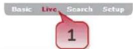
1). Select the Live tab at the top-le of the camera's browser interface.
VISIX Analytic Sensor
Figure 4-1: Opening the Live Tab
2). This will open the camera's Live Viewer.

Figure 4-2: Live Tab
For more informaon on the Live tab user interface and opons, see Secon 6.1: Live Tab.
Aer logging into the camera's browser interface, a user may view playback video recorded by the camera.
Steps:
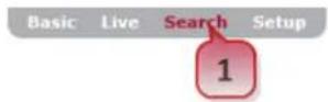
1). To view playback video, select the Search tab.
VISIX Analytic Sensor

Figure 4-3: Opening the Search (Playback) Tab
2). This will open the camera's Playback Search window.

Figure 4-3: Search (Playback) Tab
3). Set the day (search me range is automacally set to the current day).
4). Click the context arrow to reveal all search results for the selected day. All search Condions will be enabled by default. All available les, with an included thumbnail and le informaon, will be visible.
Presence Alarm
2015-12-29
11:32:11

Presence Alarm
2015-12-29
11:22:41

Presence Alarm
2015-12-29
11:21:47

Presence Alarm
2015-12-29
11:19:18


Presence Alarm
2015-12-29
11:18:20

Presence Alarm
2015-12-29
11:14:30

Presence Alarm
2015-12-29
11:13:06

Presence Alarm
2015-12-29
11:12:57


Figure 4-4: Search Result Thumbnails
5). Click the next to a le (thumbnail) to load and playback the video in the Playback Viewer.
Basic Live Search Setup
VISIX Analytic Sensor
3xLOGIC


Figure 4-5: Video File Playback
When viewing playback, the followings tools may be utilized:
| Playback Tools | Descripon |
| Download a snapshot of the current frame to your local system. | |
| Download the clip to your current system | |
| View the video in full-screen mode | |
| AutomacPlayback Next File | Playback all available les sequenally in the order they were recorded. |
6). Use the navigaon controls at the boom of the page to navigate mulple pages of search results.
For more informaon on the Search (Playback) Tab interface and funconality, see Secon 6.2: Search ____(Playback) Tab.
4.2 Congure VIGIL Connect Alias
VIGIL Connect allows VIGIL VMS users to remotely connect to a VIGIL Server/V-Series All-in-One camera using the system serial number or a user denied VIGIL Connect alias, without the need for extensive changes to an existing network's sengs. This allows for the device to be networked with other VIGIL suite ulies with lile eort and minimal knowledge of the device's network conncon values.
Steps:
1). To congure a VIGIL Connect alias, navigate to the camera's Basic Tab>Camera Conguraon Menu>Site Informaon Sengs page.

Figure 4-6: Conguring a VIGIL Connect Alias
2). Fill in the VIGIL Connect Alias eld with an alias of your choosing.
3). Click Apply to save the new alias.
Your VISIX V-Series All-in-One camera can now be networked with other 3xLOGIC ulies and VIGIL suite applicaons (VIGIL Client, VIGIL VCM, View Lite II(Android and iOS), 3xCLOUD, etc...) using only the camera's VIGIL Connect Alias.
4.3 Congure a Video Analycs (VCA) Rule (Analycs License Required)
ENABLING VCA
Before conguring any analycs rules, VCA (video content analysis) must rst be enabled on your All-in-One camera. An All-in-One Analycs license is required to congure and ulize VCA analycs rules on VISIX All-in-One cameras. To enable VCA:
Steps:
1). Navigate to the Setup (Advanced) Tab > VCA > Enable/ Disable sengs page.
2). Check o Enable under the VCA Conguraon secon.

Figure 4-7: Enabling VCA Analycs
Aer enabling VCA, several other conguraon opons will be deployed.
3). Under the VCA Features secon, select acve analycs type. For the purposes of this example, both Object Tracking and Counng Line will be enabled.
4). Under the Tracking Mode secon, select the analycs tracking mode. In this example, the People tracking mode is selected (People tracking requires an Advanced analycs license. If using Surveillance tracking mode, the steps in this example are sll accurate.)
5). Click Apply to save the new sengs.
VCA ANALYTICS CALIBRATION
Another preliminary step before conging VCA analycs rules is the need to calibrate the cameras for accurate analycs object recognition and tracking.
The calibraon process includes conguring the correct camera angle and eld of view, as well as the delineaon of ancipated object (people, car, etc...) size. Proper calibraon of the camera is required to ensure accurate analytics counts and tracking. To begin calibraon:
Steps:
1). Navigate to the Setup (Advanced) Tab > VCA > Calibraon sengs page.
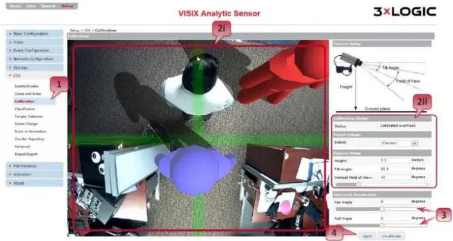
Figure 4-8: Calibrang Analycs
2). Adjust calibraon sengs as required. A user may perform basic calibraon cameras via two separate methods:
i. Click-and-Drag. - For this method, click and drag the green calibraon grid to sasfactorily emulate the camera's height, It perspective, and eld of view. The mimics may be moved around the image to help the user gauge perspective. The mouse scroll wheel is also ulized to adjust camera height, and consequently the size of the calibraon grid and mimics. Use resizing of these elements to ancipate average object size.
ii. Manual Conguraon - Manually enter/adjust calibraon values under Camera Setup. As the user enters values, the calibraon overlay on the live preview will react accordingly.
3). If required, adjust Pan Angle and Roll Angle under the Advanced Parameters secon using the slider bars. As the sliders are moved, the calibraon overlay over the preview image will react accordingly. Advanced Parameters must be entered and cannot be adjusted using Click-and-Drag.
Right-click within the video preview for the following calibraon tools:
| Right-Click Opon | Descripon |
| Virtual Ruler | Select this tool to anchor a virtual ruler from the point-of the right click.Drag your mouse across the image to extend the ruler. Use this feature to ensure accurate perspecve calibraon sengs. |
| Draw Horizon | Select this opon to add a drawn horizon line to the calibraon grid. This horizon line will be visible when the camera’s lt angle is twenty degrees or less. |
| Transparent Grid (enabled by default) | Select this opon to make the green calibraon grid transparent. |
| Add Mimic | Add another mimic to the live preview. |
| Pause | Pause the live preview image on the current frame. |
4). When you have calibrated the camera to your sasfacon, click Apply to save the new calibraon sengs.
VCA ANALYTICS RULE CONFIGURATION
Aer enabling VCA and calibrang your All-in-One camera, a VCA rule may be congured. For the purpose of this example, two separate rules: a basic counting line (tripwire) and a dwell me zone, will be congured separately.
CONFIGURING A LINE (TRIPWIRE) WITH ON-SCREEN COUNTER
Steps:
1). To congregate a VCA line, navigate to the Setup (Advanced) Tab > VCA > Zones and Rules sengs page.
2). Right-click in the video preview area and select Zone/Line>Create Line.
3). Draw the line segment as desired by clicking to place both end points
4). Assign a Name and Color to the line.

Figure 4-9: Conguring Analys Rules
Now, the manner in which the line counts objects must be congured. The two most common counting methods using a line are:
i. Presence – Count will increase whenever an object makes contact with the line, regardless of direcon.
ii. Direconal - (located under Counng Line) – Count increases when the line is crossed toward a dened direcon.
In the above example and for the purpose of this instruconal, direconal counng is used. To proceed:
5). Under the Counng Line secon of the line sengs, check-o both Direcon A and Direcon B. In the above example, Direcon A was renamed "Counng Wire 1 - Out" and Direcon B was renamed "Counng Wire 1 - In" for easy recognition.
6). Click Apply at the boom of the window to save the newly congured counng line.
The tripwire will now tally separate counts for both congured direcons. To display counts for each direcon on-screen, a VCA counter must be congured. To congure a counter for use with your counng line/tripwire:
7). Right-click within the viewing area and select Counter>Add Counter

Figure 4-10: Conguring a VCA Counter
8). Place the counter overlay in the desired posion.
9). Assign a Name and Color (In Counter and green used in the above example, respectively).
10). Congure the counter's Increment rule
i. Check o Inc 0.
ii. Set the Inc 0 value to the desired trip wire/counng line. In the above example, Inc 0 is set to increment whenever Counng Wire 1 – In is triggered.
11). Repeat Steps 7-12 to create a separate counter for Counng Wire 1 – Out
12). Click Apply to save the new counter sengs.
The tripwire should now count both direcons and display counts via the congured counters. For instrucons on previewing your analycs overlay, see Previewing Analycs Overlay.
CONFIGURING A DWELL TIMER ZONE
Steps:
1). To congregate a VCA Zone with Dwell Timer Alarm, navigate to the Setup (Advanced) Tab > VCA > Zones and Rules sengs page.
2). Right-click in the video preview area and select Zone/Line>Create Zone.
3). Draw the zone as desired by clicking and dragging each corner until a sasfactory shape and posion is achieved.
4). Assign a Name and Color to the zone.

Figure 4-11: Conguring a VCA Dwell Timer Zone
5). Enable the Dwell rule.
6). Set an appropriate dwell Threshold. 5 seconds is used in the above example.
7). Click Apply to save the new zone sengs.
An analycs dwell event(alarm) will now trigger whenever an object has spent more than 5 seconds in the dened zone. For instrucons on previewing your analycs overlay, navigate to Previewing Analys Overlay.
PREVIEWING ANALYTICS OVERLAY
Steps:
1). For a full live preview of your analytics overlay, select the Live tab.
2). In the Live viewer, right-click and select Show Counter and Show Zones to overlay counters and zones/lines.

Figure 4-12: Example 1 Counng Line (Tripwire) Analycs Overlay

Figure 4-13: Example 2 - Dwell Timer Zone Analytics Overlay
4.4 Integrang All-in-One Camera with VIGIL Server Using VIGIL Analycs Bridge
VIGIL Analycs Bridge allows stand-alone VCA analycs rules found on a 3xLOGIC VISIX All-in-One Camera web sengs to be used and processed by a VIGIL Server and other VIGIL business intelligence products. Quick conguraon within VIGIL Server and VIGIL Analycs Bridge is all that is needed to obtain analycs data directly from a 3xLOGIC All-in-One camera.
INSTALLATION OF ANALYTICS BRIDGE
The ulizaon of a 3xLOGIC All-in-One camera in VIGIL Server requires the installaon of the VIGIL Analycs Bridge program on the same system as VIGIL Server. The Analycs Bridge installer can be downloaded here from www.3xlogic.com. Once it is successfully downloaded to your computer:
Steps:
1). Double click on VigilAnalycsBridge.exe to begin the installaon.
2). You will be prompted to close all VIGIL Services. Click Close All and follow the on-screen instrucons to connue the installaon process.

Figure 4-14: VIGIL Analycs Bridge Installaon Progress
3). Once the installaon has completed, you will be prompted to reboot your system.
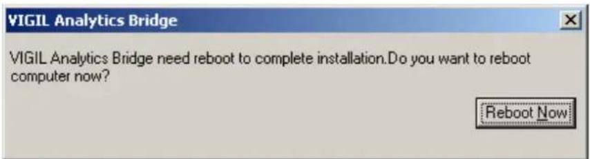
Figure 4-15: Post-Installaoon Reboot Pop-Up
4). Click Reboot Now to nalize the installaon process.
VIGIL SERVER CONFIGURATION
To congure a network camera in VIGIL Server:
Steps:
1). Click on Sengs in the icon menu toolbar on the VIGIL Server main screen. The Seings window will deploy.
2). Select the desired camera channel from the Cameras list.
3). Click the Network Camera checkbox.
4). Click the Sengs buon to launch the Network Camera Sengs window. If Network Camera was not checked before the previous step, the Network Camera Sengs window will have deployed automacally.

Figure 4-16: Conguring a Network Camera
VIGIL SERVER CONFIGURATION – NETWORK CAMERA SETTINGS
The Network Camera Sengs window is where the direct conguraon of the 3xLOGIC All-in-One camera will take place.
Steps:
1). Fill in all the required informaon and press OK.
2). Aer the Network Camera Sengs window closes, click OK or Apply to save the sengs in VIGIL Server.
VIGIL Server is able to receive video from one or many network cameras connected to the LAN or WAN. VIGIL Server currently supports several types of network cameras aside from 3xLOGIC All-in-One Cameras.
To edit a network camera at any me aer inial conguraon:
Steps:
1). Access VIGIL Server Sengs>Camera Setup Tab, select the desired network camera and click the Network Camera Sengs buon. This will open the Network Camera Sengs window.
NOTE:
The Network Camera feature disables the physical camera input on video capture cards for the selected camera channel.
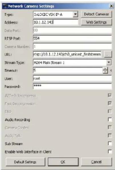
Figure 4-17: Network Camera Seings Window
| Field | Descripon |
| Type | The type of network camera. |
| Address | The IP or HTTP address of the camera. It is not necessary to include hp:// at the beginning of the HTTP address. |
| Web/Camera Sengs | Connects to the camera's web interface to make changes to the camera's internal sengs. |
| Data / RTSP Port | The network ports used to connect with the camera. |
| Camera Number | Some Network Camera types also support Encoders. Select the Camera number on the encoder to use for this network camera. |
| URL | Set this to the camera URL, if applicable. For 3xLOGIC All-in-One cameras, the url will be automacally set to rtsp:// [ip address] /ch0_unicasy_rststream |
| Stream Type | Select the video stream type for the camera: MPEG4, JPEG, or H264. |
| Timeout | The number of seconds to aempt to connect to the camera before ming out. If the meout is reached, “Signal Loss” displays in the Live Viewer window. |
| User/Password | The user name and password to connect to the camera. The default values are automacally entered. |
VIGIL ANALYTICS BRIDGE – LAUNCHING THE VIGIL ANALYTICS BRIDGE
Once the 3xLOGIC All-in-One camera has been congured in VIGIL Server, it must be congured in the VIGIL Analycs Bridge.
Steps:
1). To launch the Analycs Bridge, navigate to Start > All Programs>VIGIL and click VIGIL Analycs Bridge.
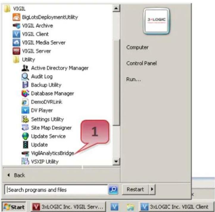
Figure 4-18: Launching VIGIL Analycs Bridge
2). If the Analycs Bridge UI does not deploy aer launching from the Windows Start Menu, locate and double-click on the Analycs Bridge quick launch icon in the Windows Task Bar (pictured below).

Figure 4-19: VIGIL Analycs Bridge Quick Launch Icon
CONFIGURING A 3XLOGIC ALL-IN-ONE CAMERA IN THE VIGIL ANALYTICS BRIDGE
The Analycs Bridge main screen is pictured below. All conguraon of the Analycs Bridge takes place from this screen.

Figure 4-20: VIGIL Analycs Bridge Main UI
| Field | Descripon |
| Add Camera | Add/Edit camera opens the Add/Edit window, pictured below. |
| Delete Camera | Deletes the currently selected camera. |
| Enable All | Enable/Disable All. Enables and disables all cameras congured in VIGIL Analycs Bridge. Disabling the cameras will stop VIGIL from perceiving the camera's analycs data. |
| Save Changes | Saves any changes done aer a new camera is congured. Will only appear aer a new camera has been congured or an exisng one has been edited. |
| Undo Changes | Undoes any conguraon changes. Will only appear aer a new camera has been congured or an exisng one has been edited. |
| Enabled | Enabled cameras will send analycs data to VIGIL Server. Disabled cameras will connue to record as normal, but will not retain any analycs data. |
| VIGIL Camera | The name of the camera as denied in VIGIL Server. |
| Type | The type of the camera: 3xLOGIC, SenTech Crosspoint, UDP or VideolQ. Select 3xLOGIC for 3xLOGIc All-in-One cameras. |
| Status | Will display either Receiving events or Stopped. Related to whether or not the camera is enabled or disabled. |
Steps:
1). To begin conguraon of the 3xLOGIC All-in-One camera within VIGIL Analycs Bridge, click Add Device.

Figure 4-21: Adding a Device to VIGIL Analycs Bridge
2). The Add/Edit Camera window will appear, shown below. Fill in all the required informaon regarding the 3xLOGIC All-in-One camera and press Load Device for a video preview from the camera.
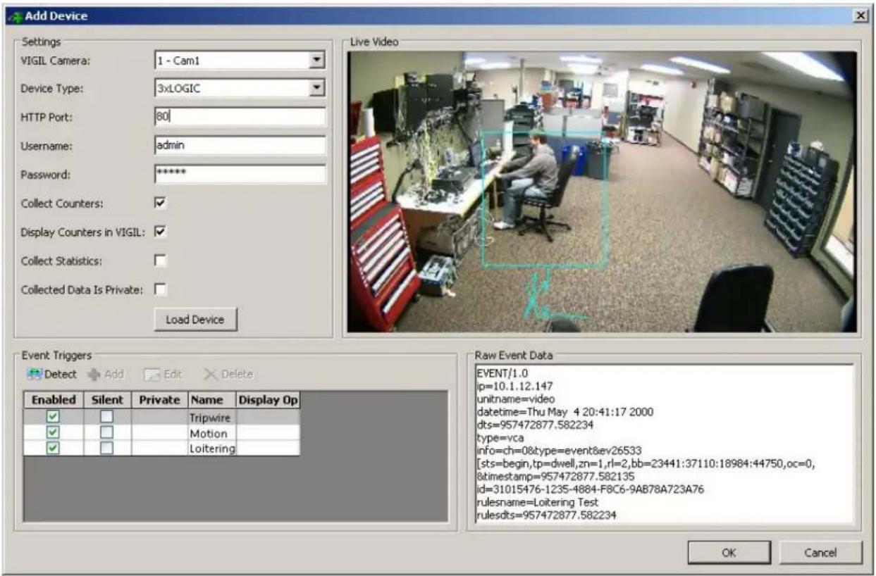
Figure 4-22: VIGIL Analycs Bridge - Add Device Window
Camera conncon and conguraon sengs are described below:
| Field | Descripon |
| VIGIL Camera | A dropdown list containing all of the cameras currently congured with VIGIL Server. |
| Device Type | The type of device/camera being edited or added. 3xLOGIC, SenTech Crosspoint, UDP or VideoIQ. Select 3xLOGIC for 3xLOGIc All-in-One cameras. |
| HTTP Port | One of two ports used to connect to the camera's analycs data. |
| Username | Username required to sign in to the camera. |
| Password | Password required to sign in to the camera. |
| Collect Counters | Enables the collecon of data counters |
| Collect Stascs | Enables the collecon of analycs stascs |
| Collected Data is Private | This feature prevents VIGIL Central Management from acquiring analycs informaon collected by the camera. |
| Load Device | Click this buon aer the other device/camera sengs have been correctly input. The device/camera's feed will be displayed in the Live Video window to the right,if available. |
| Raw Event Data | Contains a raw dump of analycs event data coming from the camera. |
| Event Triggers | Descripon |
| Detect | Detects any congured analycs rules located on the camera. |
| Add | Manually adds a rule. Adding a rule will tell VIGIL Analycs Bridge to search for a rule of that name. It will not add the rule to the camera. |
| Delete | Deletes a rule from VIGIL Analycs Bridge. |
| Enabled | Enabling a rule allows VIGIL Analycs Bridge to monitor the matching rule in the camera and place analycs data in VIGIL Server's database. The name of the rule in VIGIL Analycs Bridge is case sensitive and must be idencal to a corresponding rule in a camera. |
| Silent | Enabling the Silent opon will place analycs data for the associated rule into VIGIL Server's database, but will hide the rule from being seen by VIGIL Server. |
| Private | This eld will indicate whether or not data from this camera is being collected by VIGIL Central Management (VCM). |
| Name | The name of the rule. The rule name must be idencal to a rule located on the camera. The name is case sensitive. |
| Display Opons | Lists any acve display opons. |
3). Once you have congured camera conncon informaon, click the Detect buon to detect the analycs rules currently congured on the camera. Whenever new rules are congured on the camera, the Detect funconality must be used to update the rules in the Analycs Bridge.
4). Click OK aer detecng. The Add/Edit Device window will close.
5). On the main screen, click Save Changes. Save Changes will only appear when a camera has been added or edited. All new rule sengs will be pushed to VIGIL Server.

Figure 4-23: VIGIL Analycs Bridge - Saving Changes
Conguraon is now complete. The VIGIL Server system will now record video and data based on the 3xLOGIC All-in-One camera's-detected analytics events.
4.5 Adding All-in-One Camera to VIGIL Suite Ulies
VIGIL CLIENT - ADDING A V-SERIES ALL-IN-ONE CAMERA
Steps:
1). To interface a VISIX All-in-One Camera with VIGIL Client Launch VIGIL Client (Local Mode only; VCM mode will only display Servers from a networked VCM Server) and select Servers from the Servers top menu. This will launch the Servers window. VISIX All-in-One devices are considered edge recording devices, and thus are recognized as their own VIGIL Server within the VIGIL suite.
2). Click Add. This will deploy the Add/Edit VIGIL Server window.
3). Enable the Use VIGIL Connect opon. If connecng using tradional network connecn criteria is desired, enter the cameras IP Address/DNS Name and conrm TCP/IP port status.
4). Enter in the VIGIL Connect alias of the desired VISIX All-in-One camera (VIGILTest1 used in the below example). Skip this step if using tradional network connecon criteria (IP/Port).
5). Click Test VIGIL Connect to conrm the camera can be communicated with through the Connect system using the provided alias. Skip this step if using tradional network conncon criteria (IP/Port).
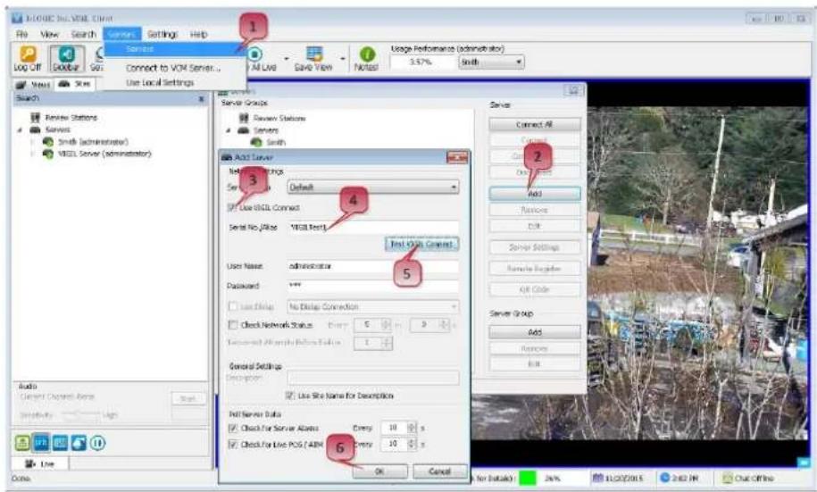
Figure 4-24: Adding All-in-One Camera to VIGIL Client
6). If the test is successful, then VIGIL Client can successfully communicate with the Server. Click OK at the boom of the Add Server window aer conguring all required elds to save the new Server to VIGIL Client. For more informaon on conguring VIGIL Servers, please see Secon 5.1 of the VIGIL Client Users Guide.
NOTE:
The camera will be visible in the Client treeview and will be represented by a icon. The camera video stream can be added to the VIGIL Client viewer in the same manner as VIGIL Server cameras; Simply extend the camera's drop-down menu and double click the icon to add it to the viewer. Alternatively, a user can drag-and-drop the camera stream icon into the desired frame of the VIGIL Client viewer.
For more informaon on conguring VIGIL Servers/V-Series All-in-One camera in VIGIL Client, please see Secon 5.1 of the VIGIL Client Users Guide.
VIGIL VCM - ADDING A V-SERIES ALL-IN-ONE CAMERA
Steps:
1). To add a VISIX All-in-One Camera to VCM for central management and health-monitoring purposes, launch a VCM Client.
2). Log into a VCM Server.
![SQL Server - VSEL Central Management - [Health Monitor] File View Server Group Tools Windows Help Log Off Search Servers Server Server Users VOM Users Health Monarch Jobs Upgrades V-POS Settings Refresh Server Groups Add Server Alerts Service Stream Print... Export... Server Group Add Server Server Group Add Server Server Group Details Name: Alky-One Camera 1 Current Server Group: Data: WebForm/TestFormes VCM Site ID: Site XML Connect Serial No./Main Text XML Connect Administrator Log: admin Password: 240 Setup Entry: No Data Connection Health Monitor Settings... Control Date Manage Server Users Manage Active Data Enable Automatic Updates Manage Active Data Only Extract Still Images on Schedule Manage POSTS IP Data Sync Time with VCM Server Manage Other Data Server Time Zones: Automatically 10 Quick for daylight saving changes Save as Default OK Cancel](/content/2026/06/1400889/images/df638a75af41ee0b861565b5f2fe475bb7c35d121ff269089cff2c154d88a49f.jpg)
Figure 4-25: Adding an All-in-One Camera to VCM
3). Click the Health Monitor buon.
4). Select (le-click) a Server Group from the Server Groups sidebar to. The All-in-One camera will be added to this group.
5). Click the Add Server buon (only available aer selecng an applicable Server Group). This will launch the Add/Edit Server form. VISIX All-in-One devices are considered edge recording devices, and thus are recognized as their own Server within the VIGIL suite, including VCM.
6). Check o VIGIL Camera. This will indicate to VCM that the device you are adding is a VISIX all-in-One camera.
7). Check-o Use VIGIL Connect. Alternatively, if you wish to use traditional network connection criteria, leave Use VIGIL Connect disabled and enter in IP/DNS Name and Port info (if using standard network conncon values, also ignore step 8 of these instrucons) for the device.
8). Enter the VIGIL Connect alias of the All-in-One camera in the Serial No./Alias eld.
9). Aer entering an alias, click Test VIGIL Connect to ensure successful communicaon with the VIGIL Connect system.
10). Fill in all remaining required elds and click OK to add the camera to your list of centrally managed VIGIL Servers/VISIX All-in-One cameras.
If you experience issues connecng to the All-in-One camera in VCM, conrm the alias that has been entered is correct. If all sengs appear to be correct, contact 3xLOGIC for further instrucon or reference Tech Tip 140028 VIGIL Connect Troubleshoot Guide for troubleshooting ps.
3XLOGIC VIEW LITE II MOBILE (ANDROID AND IOS) – ADDING A V-SERIES ALL-IN-ONE CAMERA
Steps:
1). To interface a VISIX All-in-One camera with 3xLOGIC's View Lite II mobile app, launch the View Lite II app on your mobile device (Android OS is pictured in the below screenshot, however, the process is identical in the iOS version).
2). Tap the 📁 icon to deploy the Sengs menu.
4). Tap Add VIGIL Server. This will launch the Add VIGIL Server form. VISIX All-in-One devices are considered edge recording devices, and thus are recognized as their own VIGIL Server within the VIGIL suite, including View Lite.
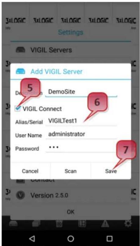
Figure 4-26: Adding an All-in-One Camera to View Lite II
5). Enable VIGIL Connect. Alternatively, if you wish to use traditional network conncon criteria, leave VIGIL Connect disabled and enter in an IP/DNS Name and Port info (if using standard network conncon criteria, also ignore step 6 of these instrucons) for the device.
6). Enter in the VIGIL Connect alias for the desired VISIX V-Series All-in-One camera (VIGILTest1 used in the above example).
7). Fill in the remaining required elds and tap Save to save the All-in-One camera to View Lite II. A user may now add the camera stream to the View Lite viewer using the same process as adding VIGIL Server or 3xCLOUD networked cameras.
3XCLOUD CROSS-PLATFORM WEB CLIENT – ADDING A V-SERIES ALL-IN-ONE CAMERA
Steps:
1). To interface a VISIX All-in-One camera with a 3xCLOUD web client account, login to your 3xCLOUD account (www.3xlogiccloud.com).

Figure 4-27: Adding an All-in-One Camera to a 3xCLOUD Account
2). Click the button to open the Sengs menu.
3). Select the Servers icon.
4). Click the + Add Servers.. buon (not pictured above). This will deploy the Add/Edit VIGIL Server form. VISIX All-in-One devices are considered edge recording devices, and thus are recognized as their own VIGIL Server within the VIGIL suite, including 3xCLOUD.
5). Click the By Serial No./Alias tab to congregate the Server with a VIGIL Connect alias. If using tradional network conncon criteria is desired, click the By IP Address and Port buon enter in an IP and Port info (if using standard network conncon criteria, also ignore step 6 of these instrucons) for the device.
6). Enter the VIGIL Connect alias of the desired All-in-One camera in the Serial No./Alias eld (VIGILTest1 used in the above example).
7). Fill in all required elds and click Add to save the All-in-One camera to your 3xCLOUD VIGIL Server list.
The All-in-One camera should now be available to add to your 3xCLOUD layout. If you experience conncon issues, conrm the conncon info (IP Address and Port/VIGIL Connect Alias) you entered is correct. If all sengs appear to be correct, contact 3xLOGIC for further instrucon or reference Tech Tip 140028 VIGIL Connect Troubleshoot Guide for troubleshooting ps.
4.6 Reboot and Reset to Factory Default Procedures
REBOOTING THE CAMERA USING THE RESET BUTTON
Steps:
1). Press the reset buon for 2 seconds while the device is active. See the VISIX V-Series All-in-One Camera Hardware and Installaon Manual for the locaon of your parcular camera model's Reset buon.
2). Wait for the system to reboot.
NOTE:
Please do not hold the reset buon for more than 2 seconds. Otherwise, the camera may be switched to its Factory Default sengs.
REBOOT THE CAMERA USING THE 3XLOGIC CAMERA SETUP UTILITY
Steps:
1). Open the 3xLOGIC Camera (VSX-IP) Setup Ulity.
2). Select your device.
3). Open Advanced Sengs.
4). Click Reboot.
REBOOT THE CAMERA VIA WEB BROWSER INTERFACE
Steps:
1). Login to the cameras web browser interface.
2). Navigate to Basic Tab> Camera Conguraon Menu > Maintenance.
3). Click the Reboot buon.
4). You will be prompted to conrm the reboot process. Click OK to proceed.
RESETTING CAMERA SETTINGS TO FACTORY DEFAULT
Reseng the device back to the factory default will reinitialize all parameters including the IP address back to the factory defaults. To reset back to the factory default:
Steps:
1). Press the reset buon and hold it while the device is in use.
2). Release the buon aer 10 seconds.
3). Wait for the system to reboot.
| Factory Default Connecon Sengs | |
| IP address | 192.168.xx.yy |
| Network Mask | 255.255.0.0 |
| Gateway | 192.168.0.1 |
| Username | Admin |
| Password | 12345 |
RESET TO FACTORY DEFAULT SETTINGS VIA CAMERA WEB INTERFACE
Steps:
1). Login to the camera's browser interface.
2). Navigate to Basic Tab> Camera Conguraon Menu > Maintenance sengs form.
3). Click the Reset Camera Sengs buon.
4). You will be prompted to conrm the factory reset process. Click OK to proceed.
5 Basic Tab
The initial landing page of the VISIX V-Series All-in-One Camera web interface is the Basic Tab > Camera Status > Status page.
NOTE:
Some UI components (logo, page tle, locaon of minor sengs within page hierarchy, etc...) may vary depending on rmware series version, VIGIL soware version, and licensing. However, operaon of all components and sengs, regardless of their locaon within the UI remains unchanged.
5.1 Camera Status Menu
STATUS
Steps:
1). The Basic Tab>Camera Status > Status page is the initial landing page aer logging into the camera. This page provides at-a-glance informaon regarding the camera's conguraon and status, as well as storage status.

Figure 5-1: Basic Tab – Camera Stratus-Status Page
| Status Indicator | Descripon | |
| Camera Informaon | The Camera Informaon secon provides at-a-glance informaon regarding:■ Camera Model ■ VIGIL Soware Version ■ VIGIL Connect Alias ■ Site Name | ■ Camera Firmware Version ■ Camera MAC Address ■ Company Name ■ Camera Name |
| Camera Status | The Camera Status secon provides at-a-glance informaon regarding:■ Camera Current ■ CPU Usage % ■ UPnP Status | ■ Timezone ■ Memory Availability ■ Internet Connecon Status |
| Storage Status | The Storage Status secon provides at-a-glance informaon regarding:■ Storage Device Status ■ Free Space | ■ Total Capacity ■ Recorded Footage Date/Time Range |
5.2 Camera Conguraon Menu
SITE INFORMATION
Steps:
1). Opening the Basic Tab>Camera Conguraon drop-down menu and clicking the Site Informaon link will open the Site Informaon sengs page.

Figure 5-2: Basic Tab – Camera Conguraon – Site Informaon Form
2). From the Site Informaon page, a user may edit site informaon sengs
Conguraon sengs including:
| Field | Descripon |
| Company Name | The name of the company that owns the camera. |
| Site Name | The name of the eld site in which the camera is deployed. |
| Camera Name | The name of the cameras. This will be used to identify the camera throughout the VIGIL soware suite. |
| VIGIL Connect Alias | VIGIL Connect allows VIGIL VMS/VISIX V-Series All-in-One users to remotely connect to a VIGIL Server/V-Series All-in-One camera using the system serial number or a user dened VIGIL Connect alias, without the need for extensive changes to an exisng network's sengs. |
3). Aer nishing conguraon, click Apply to save the new sengs.
TIME
Steps:
1). Opening the Basic Tab>Camera Conguraon drop-down menu and clicking the Time link will open the Time sengs page.

Figure 5-3: Basic Tab – Camera Conguraon – Time Seings
2). From the Time page, a user may view the camera's current me or choose the camera's me zone. Aer nishing conguraon, click Apply to save the new sengs.
NOTE:
Advanced me sengs (manual me conguraon, me synchronizaon method, etc...) can be congured from the Advanced Tab> Basic Conguraon Menu>Time page.
USERS
Steps:
1). Opening the Basic Tab>Camera Conguraon drop-down menu and clicking the Users link will open the Users sengs page.
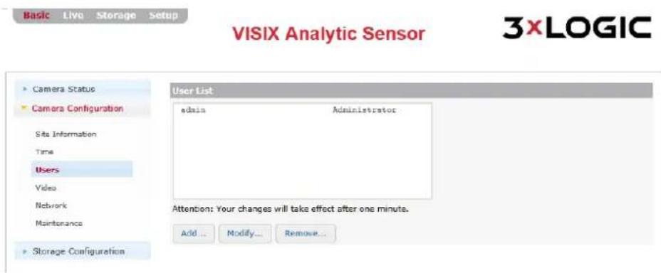
Figure 5-3: Basic Tab – Camera Conguraon - Users Sengs
2). From the Users page, a user may view the camera's list of user proles. A user may also add, modify or remove a user prole. Details regarding each acon are outlined in the proceeding sub-seconds of this manual.
ADD A USER
Steps:
1). Click the Add... to add a new user prole. The Add User form (pictured right) will deploy.
| Form Field | Descripon |
| Username and Password | Enter a username and password for the new user. |
| Conrm Password | Conrm the previously entered password. |
| User Group | Choose a User Group for the user. |

Figure 5-4: Add a User
2). Aer nishing conguraon, click Apply to save the new sengs.
MODIFY A USER
Steps:
1). Click the Modify...buon to modify an exisng user prole. The Modify User form (pictured right) will deploy.
| Form Field | Descripon |
| Username and Password | Enter a username and password for the new user. |
| Conrm Password | Conrm the previously entered password. |
| User Group | Choose a User Group for the user. |
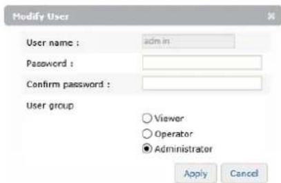
Figure 5-5: Modify a User
2). Aer nishing conguraon, click Apply to save the new sengs.
REMOVE A USER
Steps:
1). Click the Remove buon to remove an exisng user prole. This acon is only available when a user prole is selected in the list.
2). You will be prompted for a conrmaon before nalizing the removal.
VIDEO
Steps:
1). Opening the Basic Tab>Camera Conguraon drop-down menu and clicking the Video link will open the Video sengs page.

Figure 5-6: Basic Tab – Camera Conguraon – Video Sengs
From the Video page, a user may edit a camera's Main Stream and Sub Stream video sengs.
| Stream Sengs | Descripon |
| Enable Streaming | Check this box to enable the chosen stream. |
| Resoluon | Set the chosen stream’s resoluon. Full-resoluon is generally reserved for main-stream. A smaller, less data-intensive resoluon is generally reserved for sub stream. |
| Max FPS | Set the camera’s maximum Frames-Per-Second value. A higher FPS is generally reserved for main stream, while a lower, less data-intensive value is generally reserved for sub stream. |
NETWORK
Steps:
1). Opening the Basic Tab>Camera Conguraon drop-down menu and clicking the Network link will open the Network sengs page.
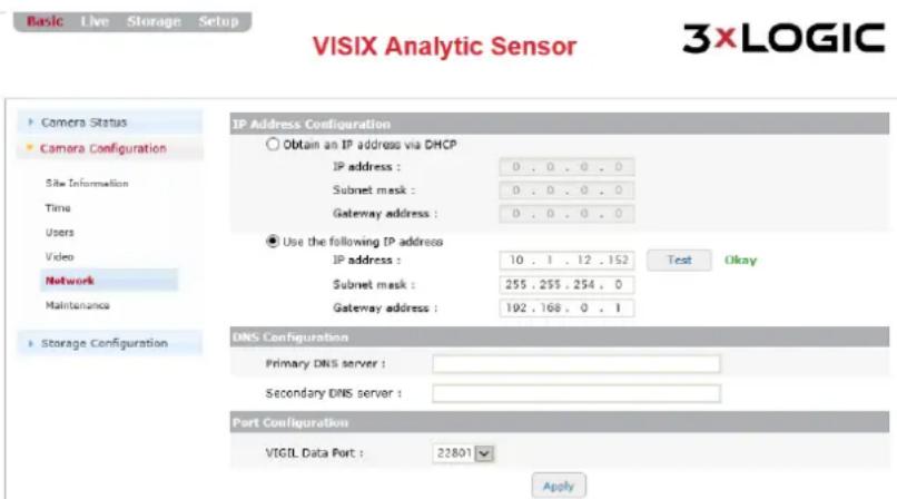
Figure 5-7: Basic Tab – Camera Conguraon – Network Seings
2). From the Network sengs page, a user may edit a camera's IP Address Conguraon, DNS Conguraon and Port Conguraon.
| Network Seng | Descripon |
| IP Address Conguraon | Select the method by which the cameras will obtain an IP address:Obtain an IP Address via DHCP – Select this method to have your router’s DHCP funcon automacally assign the camera’s network conneconsengs. This method is enabled by default. The automacally-generated IP, Subnet Mask and Gateway addresses will be listed directly underneath.Use the following IP Address (Manual Conguraon) – Select this oponto manually enter network connecosengs. IP Address, Subnet Maskand Gateway Addresses can be manually entered directly underneath this sengs. Clicking the Test buon will conrm the validity of thenetwork connecos values you have entered. |
| DNS Conguraon | Enter in Primary and Secondary DNS Server connecosinformaon. |
| Port Conguraon | Select the VIGIL Data Port. 22801 is the default and is the recommended port number by 3xLOGIC. |
MAINTENANCE
Steps:
1). Opening the Basic Tab>Camera Conguraon drop-down menu and clicking the Maintenance link will open the Maintenance sengs page.

Figure 5-8: Basic Tab – Camera Configuraon – Network Seings
2). From the Maintenance sengs page, a user may perform basic maintenance funcons such as pushing a rmware or VIGIL soware update to the camera, reboot the camera or reset the camera to factory default sengs.
| Maintenance Seng | Descripon |
| Upload Firmware Image | The current rmware and VIGIL soware version of the camera is listed: Click the Browse buon to open a le browser and locate the rmware update le. |
| Reboot | Click the Reboot buon to restart the device. You will be prompted to conrm the reboot process. Click OK to proceed. |
| Reset Camera Sengs | Click the Reset Camera Sengs buon to reset all custom congured sengs to factory default. You will be prompted to conrm the factory reset process. Click OK to proceed. |
| Automac Firmware Upgrade | Enable automac rmware upgrade. The camera will poll an update cloud server hosted by 3xLOGIC for new rmware and will apply an update when available. |
5.3 Storage Conguraon Menu
SD CARD
Steps:
1). Opening the Basic Tab>Storage Conguraon drop-down menu and clicking the SD Card link will open the SD Card sengs page.

Figure 5-9: Basic Tab – Storage Configuraon – SD Cards Sengs
2). From the SD Card storage sengs page, a user may choose their SD storage device, view informaon on the chosen device, change storage format or mount and eject storage devices.
SD STORAGE LIST
In the SD Storage List secon, a user may select their desired storage device from the list. The following device details will be generated to the right of the device list aer making a selecon.
| Storage Detail | Descripon |
| Disk | The storage device disk type of the selected device. |
| Type | The storage disk format of the selected device. |
| Total Capacity | The totally storage capacity of the selected device. |
| Free Space | Lists the remaining free space on the selected device. |
| Status | Current storage device status. |
RECORDING DEVICE CONTROL
In the Record Device Control secon, a user may select the desired storage format (vfat, ext3) and can also mount an inactive storage device or eject the currently active storage device.
| Device Control | Descripon |
| Format (vfat) | Use vfat format for the selected device. Format progress will be displayed.WARNING: Re-formang the storage device will wipe all stored footage.Download any footage you wish to retain before beginning the format process. |
| Format (ext3) | Use ext3 format for the selected device. Format progress will be displayed.WARNING: Re-formang the storage device will wipe all stored footage.Download any footage you wish to retain before beginning the format process. |
| Mount | Mount the currently selected device. This opon is only available if the currently selected device is inactive. |
| Eject | Eject the currently selected device. This opon is only available if the selected device is mounted. |
6 Live and Search (Playback) Tabs
6.1 Live Tab
Aer logging into the camera's browser interface, a user may view live video from the camera. To view live video:
Steps:
1). Select the Live tab at the top-le of the camera's browser interface.
VISIX Analytic Sensor
Figure 6-1: Opening the Live Tab
This will open the camera's Live Viewer.
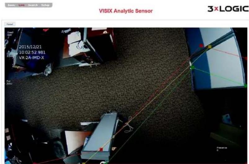
Figure 6-2: Live Tab
LIVE VIEWER – OPTIONS PANEL – OPTIONS TAB
Steps:
1). Clicking the Panel buon and selecng the Opons tab will open the Opons panel.
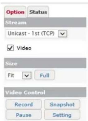
Figure 6-3: Live Tab Opons
Live Viewer opons are described below:
| Opon | Descripon |
| Stream | Select the stream and protocol type (UDP or TCP).Unicast and Mulcast(UDP only) stream types can be selected can be applied to either the 1^st (Main) or 2^nd (Sub) streams.EXAMPLE:If a user selectsUnicast – 2^nd (TCP)the live stream will be unicast, using 2^nd (sub) stream prole sengs and UDP as its transmission layer protocol. |
| Size | Select the video size.SelectFitto stretch the image to t your browser. Select a percentage to display the image at the selected percentage of its nave resoluon. |
| Video Control | Live view video controls are as follows:Record– Click Recordto begin recording a footage le separate of recording sengs or the current recording mode. When you have recorded sucient footage, click theStopbuon. The recorded le will be automacally downloaded to your local system’sMy Document/Documentsfolder by default. This desnaon can be edited in theVideo Opons Panel>Sengsinterface.Pause– Pause the live viewer on the current frameSnapshot- ClickSnapshotto capture a sll image of the current live frame. The snapshot will be automacally downloaded to your local system’sMy Document/Documentsfolder by default. This desnaon can be edited in theVideo Opons Panel>Sengsinterface.Sengs–Click this buon to open the live video sengs window.From this window,Local RecordingandSnapshotsengs can be congured.a.Local Recording– Edit local recording sengs including local recording desnaon (clickBrowseand select a desnaon on your local system), lename prex, recording resources and maximum le size/duraon. See Secon 0 for more detailed informaon regarding recording sengsSIGNSHOT– Edit snapshotsengs including snapshot export desnaon (clickBrowseand select a desnaon on your local system), and lename prex. |
LIVE VIEWER – OPTIONS PANEL – STATUS TAB
Steps:
1). Clicking the Panel buon and selecng the Status tab will open the Status panel. From the Status panel, a user may view the below at-a-glance informaon related to the live video stream.

Figure 6-4: Live Tab Status
6.2 Search (Playback) Tab
Aer logging into the camera's browser interface, a user may search for and view playback (recorded) footage from the camera. To open the Search tab:
Steps:
1). Select the Search tab link at the top-le of the camera's browser interface.

Figure 6-5: Opening the Search (Playback) Tab
This will open the Playback Search form and viewing area.

Figure 6-6: Search (Playback) Tab
When searching for playback, the following controls may be utilized:
| Search Tools | Descripon |
| [3BDH] 2016-01-21 | Select the date (merange) for your search. Footage will be searched from 00:00-24:00 on the selected day. |
 | Click this buon to re-run the search using any new search parameters that have been changed. |
| Condions | Condions can be used similar to tradional search Iters. Selecng specic condions will Iter out any footage les that do not meet the condional requirements. (e.g. If VCA and Moons are selected, then only playback clips recorded due to VCA and/or Moon event triggers will be returned by the search. All search Condions will be enabled by default.).The background color of each condional check-box will also be used to identify clips of a specic condion within the visual search result meline. |
When the Search tab opens initially, a search using all Condions will be performed by default.
To perform a custom search:
Steps:
1). Set the day (search me range is automacally set to the current day).
2). Select your desired conditions
3). Click the buon to run the search.
A Visual Search Result Timeline (see below example), color coded according to condions, will be visible. Click within the meline and use the mouse scroll-wheel to zoom in and out of the meline to expand or narrow down the visible me range.
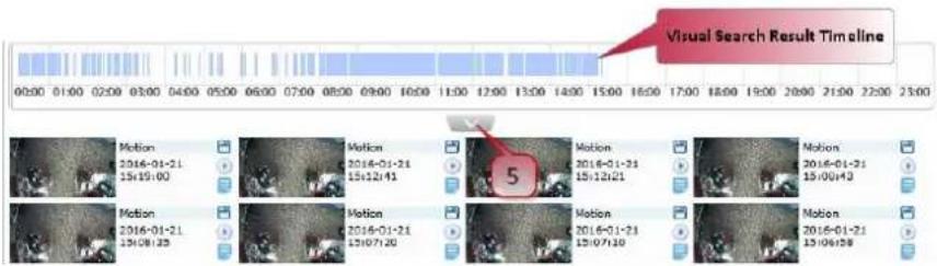
Figure 6-7: Visual Search Result Timeline and Search Result Thumbnails
4). Click the context arrow to reveal all search results as thumbnails.
Each search result thumbnail features the following le controls:
| File Control | Descripon |
| Download | Download the le to your browsers Downloads directory. |
| Playback File | Playback the le in the viewer. |
| Recording File Info | Mouse-over this icon to deploy a pop-up featuring metadata and duraon info for the selected footage.Recording File InformationDescription(md): zone1, status=detect Duration: 00:00:13 |
5). To playback video, click the buon next to the search result thumbnail for the desired le. The le will begin playback in the viewing area.

VISIX Analytic Sensor

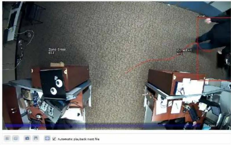
Figure 6-5: Video File Playback
When viewing playback, the followings tools may be utilized:
| Playback Tools | Descripon |
| Standard playback controls: Play, Stop, Pause. | |
| Click this buon to download a snapshot of the current frame to your local system. | |
| Click this buon to download the clip to your current system | |
| Click this buon to view the video in full-screen mode | |
| Automac Playback Next File | Check-o this box to playback all available les sequenally in the order they were recorded. A le must be selected and manually started to begin the sequence. |
6). Use the navigaon controls at the boom of the page to navigate mulple pages of search results.
7 Setup (Advanced) Tab
To congure advanced device sengs, select the Setup (displayed as Advanced on some rmware versions) tab.


Figure 7-1: Opening the Setup (Advanced Sengs) Tab
The le-side drop-down menu will now be populated with several new sengs categories for advanced users wishing to customize advanced image/video, network, event, VCA and maintenance sengs.
7.1 Basic Conguraon Menu
USERS
Steps:
1). Opening the Setup Tab>Basic Conguraon drop-down menu and clicking the Users link will open the Users sengs page.

Figure 7-2: Setup Tab – Basic Conguraon Menu – Users Sengs
2). From the Users page, a user may view the camera's list of user proles. A user may also add, modify or remove a user prole. Details regarding each acon are outlined in the proceeding sub-seconds of this manual. User sengs can also be edited from the Basic Tab>Camera Conguraon>Users sengs page.
ADD A USER
Steps:
1). Click the Add... to add a new user prole. The Add User form (pictured right) will deploy.
| Form Field | Descripon |
| Username and Password | Enter a username and password for the new user. |
| Conrm Password | Conrm the previously entered password. |
| User Group | Choose a User Group for the user. |
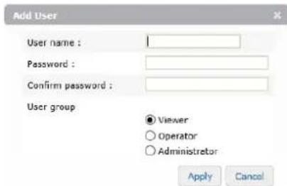
Figure 7-3: Add a User
2). Aer nishing conguraon, click Apply to save the new sengs.
MODIFY A USER
Steps:
1). Click the Modify...buon to modify an exisng user prole. The Modify User form (pictured right) will deploy.
| Form Field | Descripon |
| Username and Password | Enter a username and password for the new user. |
| Conrm Password | Conrm the previously entered password. |
| User Group | Choose a User Group for the user. |

Figure 7-4: Modify a User
2). Aer nishing conguraon, click Apply to save the new sengs.
REMOVE A USER
Steps:
1). Click the Remove buon to remove an exisng user prole. This acon is only available when a user prole is selected in the list.
2). You will be prompted for a conrmaon before nalizing the removal.
USER AUTHENTICATION
Steps:
1). Check-o Enable Anonymous Viewer Login to enable anonymous viewing (no username or password required) of the camera's live view.
TCP/IP
Steps:
1). Opening the Setup Tab>Basic Conguraon drop-down menu and clicking the Users link will open the Users sengs page.

Figure 7-5: Setup Tab – Basic Conguraon Menu – TCP/IP Sengs Form
2). From the TCP/IP sengs page, a user may edit a camera's TCP/IP sengs. This includes all congorable sengs from the Basic Tab>Camera Conguraon> Network sengs page (IP Sengs, DNS Server sengs) as well as the ability to enable IPv6 and congure host name and local link address details.
| Network Seng | Descripon |
| IP Address Conguraon | Select the method by which the cameras will obtain an IP address:Obtain an IP Address via DHCP – Select this method to have your router’s DHCP funcon automacally assign the camera’s network conneconsengs. This method is enabled by default. The automacally-generated IP, Subnet Mask and Gateway addresses will be listed directly underneath.Use the following IP Address (Manual Conguraon) – Select this oponto manually enter network connecosengs. IP Address, Subnet Maskand Gateway Addresses can be manually entered directly underneath this seng. Clicking the Test buon will conrm the validity of thenetwork connecos addresses you have entered.To enable IPv6 protocol, click Enable IPv6. For more informaon on IPv6sengs, seeIPv6Sengs Conguraon,below. |
| DNS Conguraon | Enter in Primary and Secondary DNS Server connecosinformaon. |
| Host Conguraon | Congure the device host name. |
| Link – Local Address | Checking-o Enable Auto-conguraon Link-Local Address will generatean alternate internal IP address which can also be used to connect to thecamera, access the UI via browser, etc... when on the same network asthe camera. |
BASIC CONFIGURATION MENU - TCP/IP SETTINGS - IPV6 SETTINGS CONFIGURATION
Steps:
a. When the enable IPv6 box is checked, IPv6 sengs elds will deploy (pictured below).

IP address (Information) :
√ Enable accept router advertisements
√ Enable DHCP
DHCP type :
IP address :
Prefix length :


Default router :
Figure 7-6: Setup Tab – Basic Configuraon Menu – TCP/IP Sengs – IPv6 Sengs
| IPv6 Seng | Descripon |
| Enable Accept Router Adversements | Enable Accept Router Adversements will allow the camera to accept router adversements, signaling device availability and connectivity to the host router. |
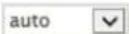
| Enable DHCP | Enable DHCP for automac IP address assignment. Select a DHCP Type from the drop-down menu. |
| IP Address | The device IP address. If DHCP is not enabled, the user may assign an address. |
| Prex Length | Assign an address prex length. |
| Default Router | Enter the default router address |
DATE & TIME
Steps:
1). Opening the Setup Tab>Basic Conguraon drop-down menu and clicking the Date & Time link will open the Date & Time sengs page.
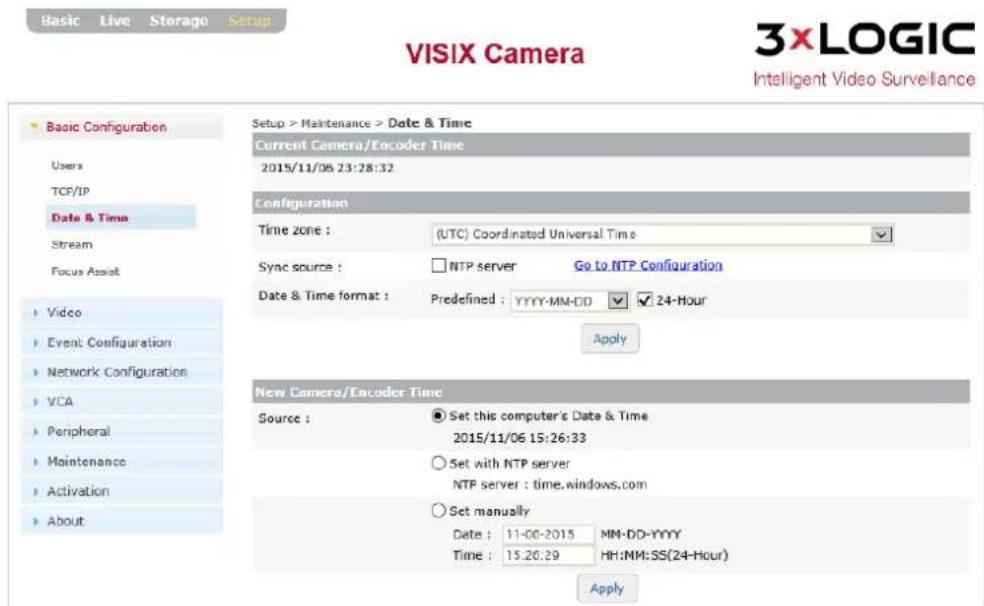
Figure 7-7: Setup Tab – Basic Configuraon Menu – Date & Time Seings
2). From the Date & Time sengs page, a user may edit a camera's me sengs including me zone, me server, date and me format and me synchronizaon source.
| Time Seng | Descripon |
| Current Camera Encoder Time | Displays the current camera me |
| Conguraon | Time Zone - Select the camera me zone.Sync Source - Set the acve NTP server as your me sync source. Click the Go to NTP Conguraon to be taken to the NTP Sengs page.Date and Time Format – Choose a predened date-format. Enable 24-Hour to use standard 24 hour me. |
| New Camera / Encoder Time | Set this Computer’s Date and Time – Selecng this opon will sync the camera’s me with your current computer system.Set with NTP Server - Selecng this opon will sync the camera’s me with the displayed NTP server (Default: me.windows.com)Set Manually – Select this opon to manually congure the camera’s date and me. |
3). Click Apply to save the new me sengs.
STREAM
Steps:
1). Opening the Setup Tab>Basic Conguraon drop-down menu and clicking the Stream link will open the Stream sengs page.
NOTE:
Advanced stream sengs can also be accessed from the Setup Tab>Video Menu>Stream link.

Figure 7-8: Setup Tab – Basic Configuraon Menu – Stream Sengs
STREAM SETTINGS
Select your desired stream prole tab (First/Main, Second/Sub) and check-o Enable Streaming to enable the chosen stream. In most cases, high quality image sengs are reserved for the main/rst stream, while lower quality, less bandwidth-intensive sengs are reserved for the second/sub I stream.
The following sengs can be congured for your chosen stream.
| Stream Seng | Descripon |
| Video Codec | Select the stream’s video codec from the opons in the drop-down menu. |
| Resoluon | Select the stream’s video resoluon from the opons in the drop-down menu. |
| Max FPS | Set the maximum Frames per Second value for the selected stream. |
| GOP | Set the Group of Picture value (I-Frame interval) for the selected stream. |
| Prole Idencaon | |
| Bit Rate Control | Congure bit rate sengs for the selected streams:■ Variable Bitrate (VBR) – Have the camera adjust bitrate for the selected stream based on an image quality preference. Choose your preference from the drop-down.■ Constant Bitrate (CBR) – Congure a target bitrate for the selected stream. |
Steps:
1). Click the Show Prole List buon for a list of preexisting encoder proles. Exising proles can be loaded by selecng them from the list and clicking Load Prole Sengs. Encoder proles can be congured from the Encoder Proles sengs form (Setup Tab>Video Menu>Encoder Prole).
2). Click Apply to save new sengs changes.
SNAPSHOT SETTINGS
Steps:
1). Click the Snapshot tab to open the Snapshot sengs. Snapshot (sll image) sengs can be congured from this form.
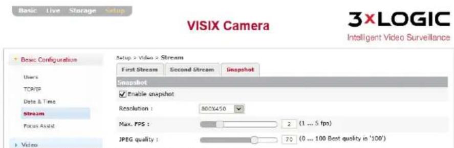
Figure 7-9: Setup Tab – Basic Configuraon Menu – Snapshot Stream Sengs
2). Click the Enable buon to enable camera sll shots via the camera browser interface (VIGIL ulies interfaced with the device such as VIGIL Client can take snapshots regardless of the camera sengs).
The following sengs can be congured for camera snapshots:
| Snapshot Seng | Descripon |
| Resoluon | Select the snapshot image resoluon from the opons in the drop-down menu. |
| Max FPS | Set the maximum Frames per Second value for snapshot images using the slider. The smaller FPS range of 1-5 helps to prevent incorrect sll shots from lag or delay. 1 is the default seng and is recommended for nearly all use-cases. |
| JPEG Quality | Set the JPEG quality value for snapshot images using the slider. |
FOCUS ASSIST
Steps:
1). Opening the Setup Tab>Basic Conguraon drop-down menu and clicking the Stream link will open the Stream sengs page.

Figure 7-10: Setup Tab – Basic Conguraon Menu – Focus Assist Sengs
2). The Focus Assist tool is an auto-focus funcon intended to aid the user in achieving opmal lens focus to obtain the clearest image possible. Click Start to begin the focus assist process. When the image aains the desired focus level, click Stop.
3). Click View to close or open the video preview. Click Pop-Up to open the video preview in a separate browser window.
7.2 Video Menu
CAMERA
Steps:
1). Opening the Setup Tab>Video drop-down menu and clicking the Camera link will open the Camera sengs page. A video preview is available at the boom of the sengs form. When conguring the sengs described below, be sure to scroll-down and check the video preview as necessary.
2). Click the Apply buon at the boom of the sengs form (above the video preview) to apply sengs changes. Click the Preview buon to toggle the video preview on/o. Click the Pop-Up buon to open the preview in a separate browser window.
GENERAL SETTINGS
Steps:
a. Under the General secon, a user may set the device name.
Setup > Video > Camera
General
Friendly name :
Full HD Indoor / Outdoor IR Bullet IP Camera
Figure 7-11: Setup Tab – Video Menu – Camera Setngs – General
VIDEO APPEARANCE SETTINGS
Steps:
1). Under the Video Appearance seconds, a user may adjust video image sengs including Brightness, Contrast, Saturaon and Sharpness.
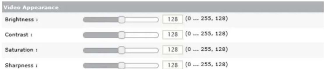
bar
| Video Appearance | Value | | --------------- | ----- | | Brightness | 128 | | Contrast | 128 | | Saturation | 128 | | Sharpness | 128 |Figure 7-12: Setup Tab – Video Menu – Camera Setngs – Video Appearance (Image) Setngs
VIDEO TRANSFORM SETTINGS
Steps:
1). Under the Video Transform secon, a user may vercal or horizontally ip their image by selecng the Vercal Flip or Horizontal Mirror opon, respectively.
2). A digital image rotaon (does not work with PTZ hardware) seng can also be chosen; Le (-90 Degrees) and Right (+90 Degrees). This will digitally alter the image to give the appearance of a eld-of-vision which has been rotated from the camera's actual xed posion.
Video Transformaon sengs may be automacally disabled depending on the presence of other camera sengs. Conicng sengs will be listed (orange text, below).

Figure 7-13: Setup Tab – Video Menu – Camera Setngs – Video Transform
EXPOSURE SETTINGS
Steps:
1). Under the Exposure secon, a user may congure the following sengs:

Figure 7-14: Setup Tab – Video Menu – Camera Setngs – Exposure Sengs
| Exposure Seng | Descripon |
| Exposure Mode | ■ Auto – The camera will automatically adjust shuer speed based on environmental conditions and activity within the camera's eld-of-vision. Congure a Maximum Exposure Time and Minimum Exposure Time to establish an operable range for automac adjustments.■ Manual – Manually assign a stac Shuer Speed.■ Flickerless – Enable Flickerless exposure mode. Set display system sengs to either PAL (50Hz) or NTSC (60Hz). The opmal sengs will depend on the monitor receiving the video output from the camera. |
| Maximum AGC | Congure the maximum Automac Gain Control limit for the camera. Adjust this seng to improve image noise/snow distoron. The opmal seng will be dependent on the camera installaon environment. The default seng is 50. |
| Exposure Adjustment | Congure the amount of exposure steps. One EV is to be considered one exposure step. |
| Backlight Compensaon | Enable Backlight Compensaon. Backlight compensaon adjusts exposure to ensure a larger poron of the eld-of-vision remains bright and visible when small areas of high illuminaon force the camera to decrease image brightness. |
| Digital Slow Shuer | Enable Digital Slow Shuer. The user may select the DSS speed from the drop-down menu. Increasing this seng will allow for a clearer picture in darker environment by allowing more than the normal amount of light into the camera lens. |
| IR | Congure the Infrared sengs for the camera. These sengs are only available for camera models with IR capability.■ On (Smart IR) /O – Turn the cameras smart (auto) IR adjustment capability On or O.■ Manual – Manually congregate the camera’s IR sensor illuminaon level. Drag the slider to set the cameras IR illuminaon level. 128 is the default sengs. |
DIGITAL WIDE DYNAMIC RANGE SETTINGS
Steps:
1). Under the Digital Wide Dynamic Range secon, a user may enable D-WDR and congregate the dynamic range level between 1 and 16. 8 is the default seng.

Figure 7-15: Setup Tab – Video Menu – Camera Setngs – D-WDR Seings
1). Under the Day and Night secon, a user may choose the cameras Day/Night mode seng.

Figure 7-16: Setup Tab – Video Menu – Camera Setngs – Day and Night Setngs
| Day and Night Seng | Descripon |
| Day and Night Mode | Place the camera in Day or Night mode. Select Auto to enable the camera to detect light conditions and auto-select the opmal mode accordingly. |
| Day to Night / Night to Day Level | Set the Day to Night/Night to Day light thresholds for the automac day/night mode. Default values for DtN and NtD are 1 and 3, respectively. |
WHITE BALANCE SETTINGS
Steps:
1). Under the White Balance secon, a user may choose the cameras White Balance Mode seng from the drop-down. Red and Blue color temperature sengs can also be adjusted using the slider bars.

Figure 7-17: Setup Tab – Video Menu – Camera Setngs – White Balance Sengs
IMAGE SIGNAL PROCESSING SETTINGS
Steps:
1). Under the Image Signal Processing secon, a user may congregate the cameras 2D DNR (2 Dimension Dynamic Noise Reducon) seng. Increasing this seng can reduce noise surrounding moving objects within the eld-of-vision. Adversely, this can increase blurring and smudging around stac objects.
2). If the camera is heated, Defog mode can also be enabled in this second. Aer enabling defog, the Defog Level can be selected in the drop-down menu.

Figure 7-18: Setup Tab – Video Menu – Camera Setngs – Image Signal Processing Sengs
3). The default seng is 3.
VIDEO STABILIZATION SETTINGS
Steps:
1). Under the Video Stabilizaon Sengs secon, a user may enable Video Stabilizaon for any of the camera's stream proles (First/Main, Second/Sub, and Snapshot). Check-o the box adjacent to each stream you wish to apply Video Stabilization too. The Border Fill-In seng can be chosen from the drop-down menu.
NOTE:
Video stabilizaon sengs may be automatically disabled depending on the presence of other camera sengs. Conicng sengs will be listed (orange text, below).
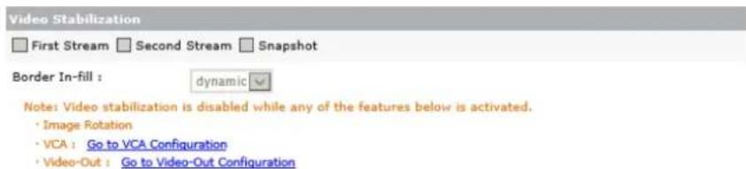
Figure 7-19: Setup Tab – Video Menu – Camera Setngs – Video Stabilization Sengs
BURNT-IN TEXT (OSD)
Steps:
1). Opening the Setup Tab>Video drop-down menu and clicking the Burnt-In Text link will open the Burnt-In Text (oen referred to as On-Screen Display or OSD) sengs page.
NOTE:
A video preview is available at the boom of the sengs form. When conguring the sengs described below, be sure to scroll-down and check the video preview as necessary.
2). Click the Apply buon at the boom of the sengs form (above the video preview) to apply sengs changes. Click the Preview buon to toggle the video preview on/o. Click the Pop-Up buon to open the preview in a separate browser window.

Figure 7-20: Setup Tab – Video Menu – Burnt-In Text Seings
3). From the Burnt-In Text sengs page, a user can enable B-I Text.
The following related sengs can be congured once BI-T has been enabled:
| BI-T Seng | Descripon |
| Include Text | Designate info to be included in the on-screen text. Choose from Date, Time and Name. |
| Text Format | Congure the Name text. I.E Camera model name or descripon (Entrance 2) |
| Text Posion | Congure the posions of the Date, Time and Name text. Select a precongured posion from the drop-down or designate custom posions using standard X and Y screen coordinates. |
ENCODER PROFILE
Steps:
1). Opening the Setup Tab>Video drop-down menu and clicking the Encoder Prole link will open the Encoder Prole sengs page.
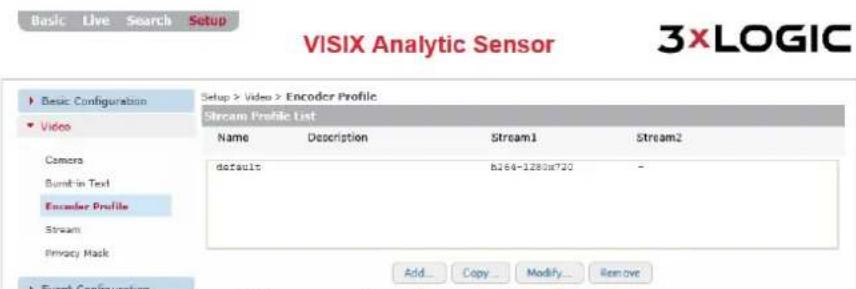
Figure 7-21: Setup Tab – Video Menu – Encoder Prole Sengs
2). From the Encoder Prole sengs page, a user may Add, Copy, Modify or Remove an Encoder Prole. An Encoder prole is a stream sengs prole that delineates camera stream sengs based on pre-congured customized sengs.
3). To Copy... or Remove.... an exisng prole, select the prole from the list and click the corresponding buon.
For informaon on adding or modifying a prole, proceed through the following secon of this manual.
ADDING OR MODIFYING AN ENCODER PROFILE
Steps:
1). To create or modify a new encoder prole, click the Add... buon (if modifying, select the desired prole from the list and click Modify...). This will deploy the below stream sengs form.

Figure 7-22: Setup Tab – Video Menu – Encoder Prole Sengs – Adding/Modifying an Encoder Prole
2). Assign/edit Prole Name and Descrilon at the top of the form and then congure stream sengs. For more details on stream sengs, please see the Setup Tab > Basic Conguraon ____. Menu> Stream Sengs secon.
3). Click OK to save the new Encoder Prole.
STREAM
Steps:
1). Opening the Setup Tab>Video drop-down menu and clicking the Stream link will open the Stream sengs page.
NOTE:
The advanced stream sengs form can also be accessed from the Setup Tab> Basic Conguraon Menu> Stream link.

Figure 7-23: Setup Tab – Video Menu – Stream Sengs
STREAM SETTINGS
Select your desired stream prole tab (First/Main, Second/Sub) and check-o Enable Streaming to enable the chosen stream. In most cases, high quality image sengs are reserved for the main/rst stream, while lower quality, less bandwidth-intensive sengs are reserved for the second/sub stream.
The following sengs can be congured for your chosen stream:
| Stream Seng | Descripon |
| Video Codec | Select the stream’s video codec from the opons in the drop-down menu. |
| Resoluon | Select the stream’s video resoluon from the opons in the drop-down menu. |
| Max FPS | Set the maximum Frames per Second value for the selected stream. |
| GOP | Set the Group of Picture value (I-Frame interval) for the selected stream. |
| Prole Idencaon | |
| Bit Rate Control | Congure bit rate sengs for the selected streams:■ Variable Bitrate (VBR) – Have the camera adjust bitrate for the selected stream based on an image quality preference. Choose your preference from the drop-down.■ Constant Bitrate (CBR) – Congure a target bitrate for the selected stream. |
Steps:
1). Click the Show Prole List buon for a list of preexisng encoder proles. Exisng proles can be loaded by selecng them from the list and clicking Load Prole Sengs. Encoder proles can be congured from the Encoder Proles sengs form (Setup Tab>Video Menu>Encoder Prole).
2). Click Apply to save new sengs changes.
PRIVACY MASK
Steps:
1). Opening the Setup Tab>Video drop-down menu and clicking the Privacy Mask link will open the Privacy Mask sengs page.
![VISIX Analytic Sensor 3xLOGIC Basic Configuration Video Camera Burn-in Test Encoder Profile Stream Privacy Mask Event Configuration Network Configuration Storage VCA Maintenance Activation About Setup > Video > Privacy Mask View 2015/12/01 10:31:12:03 VX-2A-IMD-X [001] Privacy Mask Zones Show Zone ID Name ✓ 01 2016 □ 02 2016 □ 03 2016 □ 04 2016 SAVE](/content/2026/06/1400889/images/0740b91e1946760256e95b231609d8443cd9243c65cf6c4d37bc25e79f43657c.jpg)
Figure 7-24: Setup Tab – Video Menu – Privacy Mask Sengs
From the Privacy Mask sengs, a user may draw up to four privacy masks within the camera image. A privacy mask obscures a poron of camera image in both live and recorded footage.
2). To enable a privacy mask, check-o the box in the Show column for the desired Privacy Mask. The privacy mask zone will deploy over the preview image.
3). Place and resize the zone as required.
4). Click the Save buon at the boom-right of the page to save the new privacy mask.
VIDEO OUT (BNC)
Steps:
1). Opening the Setup Tab>Video drop-down menu and clicking the Video Out link will open the Video Out sengs page. Video Out sengs will only be available on cameras with a BNC Video Out conncon.

Figure 7-25: Setup Tab – Video Menu – Video Out (BNC) Setngs
2). Select the BNC output mode. Choose between NTSC (60Hz) or PAL (50Hz, auto color correcon). The opmal seng is dependent on the monitor receiving the video output from the camera.
7.3 Event Conguraon Menu
EVENT RULES
Steps:
1). Opening the Setup Tab>Event Conguraon drop-down menu and clicking the Event Rules link will open the Event Rules sengs page.
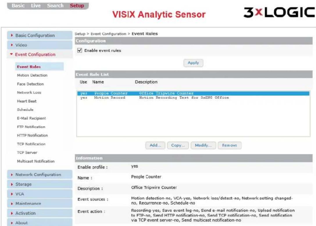
Figure 7-26: Setup Tab – Event Configuraon – Event Rules Seings
2). From the Event Rules sengs page, a user may enable and subsequently Add a new event rule. A user may also Copy, Modify or Delete and existing event rule.
3). To enable, check-off the Enable Event Rules box.
4). Select a rule from the list to display its Event Source and Event Acon specicaons under the Informaon secon.
By default, VISIX V-Series All-in-One Camera's will have events enabled and with a single moon record rule congured, designed to trigger footage recording when moon is detected. This allows for recording directly out-of-the-box with no user interacon required.
5). To copy or delete an exisng rule, select the desired rule from the list and click the Copy... or Remove buon. You may be prompted to conrm the acon. Click OK to conrm.
6). Aer adding, removing or modifying rules as desired, click the Apply buon to save changes.
ADDING OR MODIFYING AN EVENT RULE
Steps:
1). To add an event rule, click the Add... buon (if modifying, select the desired rule from the list and click Modify...). The Add/Modify Event Rule window will deploy.

Figure 7-27: Setup Tab – Event Configuraon Menu – Event Rules Setngs – Adding/Modifying a Rule - Event Source Tab
2). Check-o the Enable box.
3). Enter a Name and Descripon for the rule. This name will be used to reference this specific rule throughout the camera's browser interface.
EVENT SOURCE (TRIGGERS) TAB - ADDING/MODIFYING EVENT RULE
Steps:
1). Under the Event Source tab of the Add/Modify Event Rule form, the following event trigger sengs can be congured:
| Event Source(Trigger) Seng | Descripon |
| Moon Detecon | Enable the rule to trigger based o of Moon Detecon. Click the Go to Moon Detecon Conguraon to edit moon detecon sengs. |
| VCA Source | Enable to rule to trigger based o of a VCA (video analycs) source. (i.e. tripwire,customer not present, etc...) When this box is checked, an additional form will deployallowing the user to pick specic VCA elements as trigger criteria (pictured below). Figure 7-28: Setup Tab – Event Configuraon Menu – Event Rules Sengs – Event Source Tab - VCA SourceSengsAvailable criteria will vary based on acve VCA rules.A trigger mode can also be chosen. Select Rising Edge to trigger an event at the onsetof a VCA rule being triggered. Select Falling Edge to trigger an event at the conclusionof an event being triggered (latched). Select Both to trigger an event rule regardlessof the state of a VCA event.Click Go to VCA Conguraon to edit video analycs rule sengs. Figure 7-28: Setup Tab – Event Configuraon Menu – Event Rules Sengs – Event Source Tab - VCA SourceSengsAvailable criteria will vary based on acve VCA rules.A trigger mode can also be chosen. Select Rising Edge to trigger an event at the onsetof a VCA rule being triggered. Select Falling Edge to trigger an event at the conclusionof an event being triggered (latched). Select Both to trigger an event rule regardlessof the state of a VCA event.Click Go to VCA Conguraon to edit video analycs rule sengs. |
| Face Detecon | Enable the rule to trigger based o of facial recognition of a specic person.Click Go to Face Detecon Conguraon to edit facial recognition sengs. |
| Network Loss/Detect | Enable the rule to trigger whenever network signal loss is detected.Click Go to Network Loss Conguraon to edit network loss sengs. |
| Network SengChanged | Enable this rule to trigger whenever a network seng change is detected. |
| Storage Error | Enable the rule to trigger whenever a storage error is detected. |
| Recurrence | Enable the rule to trigger on a reoccurring basis. When selected, the user will be ableto assign a me interval for the reoccurring trigger. |
| Schedule | Enable the rule to trigger based on a schedule. The event rule will remain acve onlyduring the scheduled mes.Click the Go to Schedule Conguraon link to open the Schedule sengs andcongure a schedule as needed. The Schedule event source opon will not beavailable unl schedule sengs have been properly congured. |
EVENT ACTION TAB – ADDING/MODIFYING EVENT RULE
Steps:
1). Under the Event Action tab of the Add/Modify Event Rule form, the following event acon sengs can be congured:
Figure 7-29: Setup Tab – Event Configuraon Menu – Event Rules Sengs – Event Acon Tab
| Event Acon Seng | Descripon |
| Recording | Enable this opon to start recording footage when the rule is triggered. Recording opons (Prebuer and Postbuer values, Aach Thumbnail/Face Image opon) will be displayed when this rule is selected.Click Go to Recording Conguraons to edit recording sengs. |
| Save Event Log | Enable this opon to save an event log when the rule is triggered. Navigate to Setup Tab>Maintenance Menu> System Log sengs page for access to system event logs. |
| Send E -Mail Nocaon | Enable this opon to have the camera send an email nocaon to a recipient of your choosing whenever the rule is triggered. Email nocaon opons (To and Subject elds, Aach Thumbnail/Face Image, Aach Snapshot opons) will be displayed when the rule is selected.An email recipient must be congured to enable this opon. Click the Go to E-Mail Recipient Conguraon link to edit recipient sengs. |
| Upload Nocaon to FTP | Enable this opon to have the camera upload a nocaon (JPEG image with mestamp) to an FTP whenever the rule is triggered.Click the Go to FTP Nocaon Conguraon link to edit FTP conncon sengs. |
| Send HTTP Nocaon | Enable this opon to have the camera send a push nocaon across an HTTP service whenever the rule is triggered.Click the Go to HTTP Nocaon Conguraon link to edit HTTP conncon sengs. |
| Send TCP Nocaon | Enable this opon to have the camera send a nocaon via TCP whenever the rule is triggered.Click the Go to TCP Nocaon Conguraon link to edit TCP Nocaon sengs. |
| Send Nocaon via TCP Event Server | Enable this opon to have the camera send a nocaon via TCP Event Server whenever the rule is triggered.Click the Go to TCP Server Conguraon link to edit TCP Server conncon sengs. |
| Send Mulcast (UDO) Nocaon | Enable this opon to have the camera broadcast a UDP Mulcast nocaon whenever the rule is triggered.Click the Go to Mulcast Nocaon Conguraon link to edit Mulcast Nocaon sengs. |
MOTION DETECTION
Steps:
1). Opening the Setup Tab>Event Conguraon drop-down menu and clicking the Moon Detecon link will open the Moon Detecon sengs page.
Basic Live Search Setup
VISIX Analytic Sensor
3XLOGIC
![Setup > Event Configuration > Motion Detection View Motion Detection Face Detection Network Loss Heart Beat Schedule E-Mail Recipient FTP Notification HTTP Notification TCP Notification TCP Server Multicast Notification Network Configuration Storage VCA Maintenance Activation About [Activity - #01] Motion Zones Enable Zone ID Name Description Sensitivity ObjectSize ✓ 01 zone 200 2 □ 02 zone 128 128 □ 03 zone 128 128 □ 04 zone 128 128 □ 05 zone 128 128 □ 06 zone 128 128 □ 07 zone 128 128 □ 08 zone 128 128 Display Motion Information ✓ Show motion blob Go to RTSP/RTP Configuration ✓ Show motion activity SAVE](/content/2026/06/1400889/images/ce70706475f35a89ab91eb7dcffdb58474869353409e13da1805b711364ee6be.jpg)
Figure 7-30: Setup Tab – Event Configuraon Menu – Moon Detecon Sengs
2). From the Moon Detecon sengs page, a user may draw up to eight moon detecon zones, and acvate each as necessary.
3). Check o the Enable column box for the desired zone. This will deploy the zone over the image. Resize the zone as desired.
4). A Name, Descripon, Sensitivity and Object Size value can be assigned to each zone.
5). Enable Show Moon Blob to overlay a visualizaon of detected moon acvity on the image (the red squares in the above example).
6). Enable Show Moon Acvity to deploy a moon acvity graph as a video overlay (boom-right of the video preview in the above example). Moon acvity will only be graphed when a moon detecon zone is acvely selected within the image.
7). Click the Save buon to save changes to moon detecon sengs.
FACE DETECTION
Steps:
1). Opening the Setup Tab>Event Conguraon drop-down menu and clicking the Face Detecon link will open the Face Detecon sengs page.
Basic Live Search Setup
VISIX Analytic Sensor
3xLOGIC
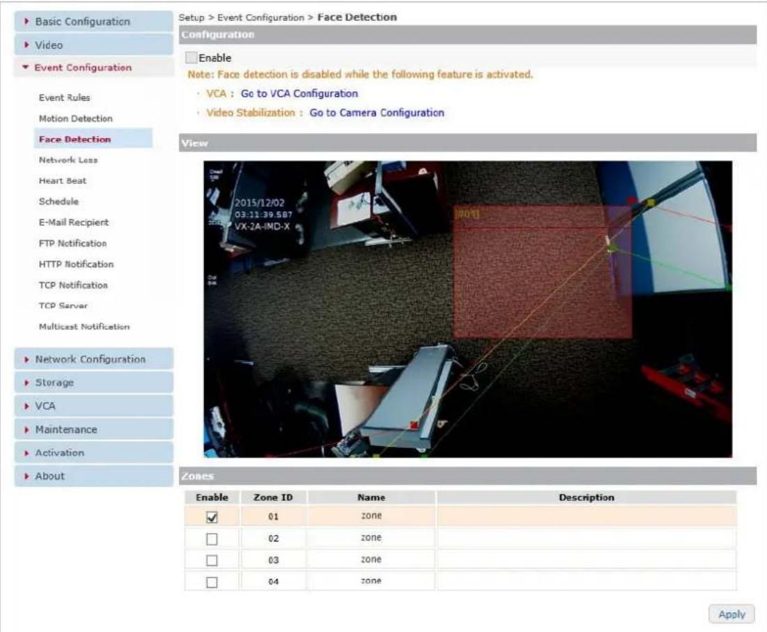
Figure 7-31: Setup Tab – Event Configuraon Menu – Face Detecon Sengs
2). From the Face Detecon sengs page, a user may draw up to four facial detecon zones, and acvate each as necessary.
NOTE:
Do not confuse Facial Detecon with Facial Recognition. Face detecon merely detects the presence of a human face. There is no Facial Recognition algorithm. The camera cannot be congured to recognize specific faces.
3). Check o the Enable column box for the desired zone. This will deploy the zone over the image. Resize the zone as desired.
4). A Name and Descripon value can be assigned to each zone.
5). Click Apply to save any sengs changes.
NETWORK LOSS
Steps:
1). Opening the Setup Tab>Event Conguraon drop-down menu and clicking the Network Loss link will open the Network Loss sengs page.

Figure 7-32: Setup Tab – Event Configuraon Menu – Network Loss Sengs
2). From the Network Loss sengs page, a user may congregate the following network signal loss sengs:
| Stream Seng | Descripon |
| Check Ethernet Connecvity | Enable the camera to check for Ethernet (physical) connecvity. |
| Check Ping Response | Enable the camera to check for network connecvity, via network ping. |
| Interval | Congure the me interval in between checks/pings. |
| Host Address | Enter the address of the device you would like the camera to ping. When this device cannot be reached/ a ping response is not received, the camera will fall into a network loss state. |
3). Click Apply to save changes to network loss sengs.
HEART BEAT
Steps:
1). Opening the Setup Tab>Event Conguraon drop-down menu and clicking the Heart Beat link will open the Heart Beat sengs page.
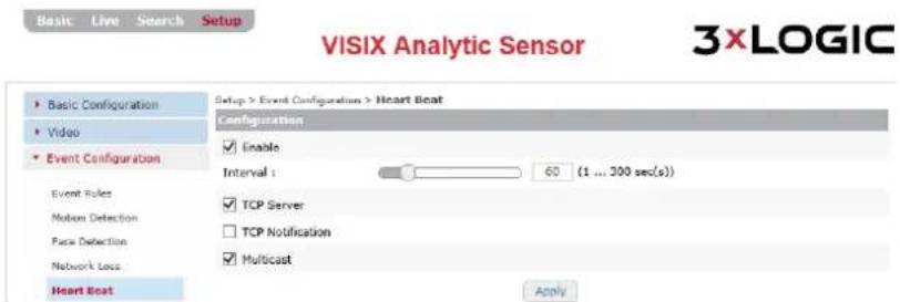
Figure 7-33: Setup Tab – Event Conguraon Menu – Heart Beat Setngs
2). In network and computer science, a Heart Beat is a periodic signal generated by hardware (or soware) to indicate normal operaon.
3). Check o Enable to activate a heartbeat signal from the camera.
Aer enabling, a user may congregate the following opons:
| Stream Seng | Descripon |
| Interval | Congure the me interval between heart beat signal broadcasts. |
| TCP Server | Enable a heartbeat signal broadcast via TCP Event Server. |
| TCP Nocaon | Enable a heartbeat signal broadcast via TCP Nocaon. |
| Mulcast | Enable a heartbeat signal broadcast via UDP Mulcast. |
4). Click Apply to save Heart Beat sengs changes.
SCHEDULE
Steps:
1). Opening the Setup Tab>Event Conguraon drop-down menu and clicking the Schedule link will open the Schedule sengs page.
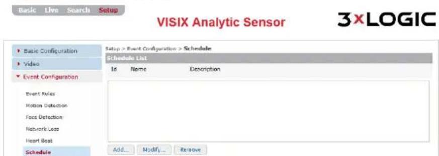
Figure 7-34: Setup Tab – Event Configuraon Menu – Schedule Sengs
2). From the Schedule sengs page, a user may Add, Modify or Remove an event schedule. When associated with a schedule, an event will trigger only during the specied me range.
3). Select a schedule from the list to display Schedule informaon.
4). To remove a schedule, select the desired schedule from the list and click Remove.
ADDING/MODIFYING A SCHEDULE
Steps:
1). To add a schedule, click the Add... buon (if modifying, select the desired schedule from the list and click Modify...). The Add to Schedule List form will deploy.
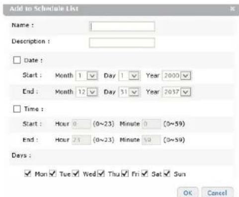
Figure 7-35: Setup Tab – Event Configuraon Menu – Schedule Sengs – Adding/Modifying Schedule
| Schedule Seng | Descripon |
| Name | Name the schedule. This name will be used to identify this parcular schedule when assigning it to an event. |
| Descripon | Provide a brief descripon of the schedule (intended use, etc...). This descripon will be displayed when the schedule is selected on the schedule sengs page. . |
| Date | Check-o the Date box to enable. If enabled, a user may congregate a Start and End date range for the schedule. |
| Time | Check-o the Time box to enable. If enabled, a user may congregate a Start and End me range for the schedule. |
| Days | Select which days of the week to apply the schedule to. |
2). Aer conguring the desired me range, click OK to save the new schedule.
E-MAIL RECIPIENTS
Steps:
1). Opening the Setup Tab>Event Conguraon drop-down menu and clicking the E-Mail Recipient link will open the E-Mail Recipient sengs page.

Figure 7-36: Setup Tab – Event Configuraon Menu – E-Mail Recipients Sengs
2). From the E-Mail Recipients sengs page, a user may Add, Modify or Remove an e-mail nocaon recipient. General recipient sengs may also be edited, including Send Rate Limit (minimum e-mail nocaon me interval) and content delivery modes (HTML Encoded or Plain Text).
3). Select a recipient from the list to display recipient informaon. To remove a recipient, select the desired recipient from the list and click Remove.
4). SMTP (E-mail Server) Sengs must be congured in order for e-mail nocaons to funcon. Click the Go to SMTP (E-Mail) Sengs link to open the SMTP sengs form and congure sengs as necessary. See SMTP (E-Mail Server) Sengs for more info.
ADD/MODIFY AN E-MAIL RECIPIENT
Steps:
1). To add a recipient, click the Add... buon (if modifying, select the desired recipient from the list and click Modify...). The Add/Modify E-Mail Recipient form will deploy.

Figure 7-37: Setup Tab – Event Configuraon Menu – E-Mail Recipients Sengs - Add/Modify a Recipient
2). Fill in the Name, Descripon and E-mail Address elds for the desired recipient.
| E-Mail Recipient Seng | Descripon |
| Name | Name the recipient. This name will be used to identify this parcular recipient when assigning it to an e-mail nocaaon. |
| Descripon | Provide a brief descripon of the recipient (intended use, etc...) This descripon will be displayed when the schedule is selected on the schedule sengs page. |
| E-Mail Address | Enter the e-mail address of the recipient. |
3). When you have lled in all the elds, click OK to save the new recipient.
FTP NOTIFICATION
Steps:
1). Opening the Setup Tab>Event Conguraon drop-down menu and clicking the FTP Nocaon link will open the FTP Nocation sengs page.

Figure 7-38: Setup Tab – Event Configuraon Menu – FTP Nocaon Sengs
2). From the FTP Nocations sengs page, a user may Add, Modify or Remove an FTP Server. Nocaons will be sent in the form of a .jpg image containing an image of the event and corresponding data (me stamp, camera name, rule, etc...)
3). To remove an exisng FTP server, select it from the list and click Remove. You will be prompted to conrm. Click OK to conrm the removal.
ADD/MODIFY AN FTP SERVER
Steps:
1). To add an FTP Server, click the Add... buon (if modifying, select the desired schedule FTP server from the list and click Modify...). The Add to/Modify FTP Nocaon List form will deploy.
![Add to FTP Notification List Name : Description : IP Address : Port (1 ... 65535) : 21 Target Directory : Account : Password : File name format : YYYYMMDD ✓ ([Device IP address]_[Channel]_YYYYMMDD_Nhhmmss [Millisecond].jpg) Test OK Cancel](/content/2026/06/1400889/images/578c4bedf992a0833e871b55918f8cf120823c318b9e77d199e3d6e4479b0c91.jpg)
Figure 7-39: Setup Tab – Event Configuraon Menu – FTP Nocaon Sengs – Add/Modify an FTP
| FTP Nocaon Seng | Descripon |
| Name | Name the FTP server. This name will be used to identify this parcular FTP when assigning it to an e-mail nocaon. |
| Descripon | Enter a descripon for the FTP. This informaon will be displayed when the FTP is selected on the FTP Nocaon sengs window. |
| IP Address/Port | Enter network conncon values for the desired FTP Server. |
| Target Directory | Enter the target desnaon directory on the FTP for the FTP nocaons. |
| Account / Password | Enter the user login credenals for the FTP. 3xLOGIC recommends using an administrave level account when possible to avoid permissions conicts. |
| Filename Format | Assign the lename format for the .jpg nocaons. |
2). Click Test to test FTP connectivity. If the test fails, conrm the correct sengs have been entered for the selected FTP server.
3). Click OK to save the new FTP server sengs.
HTTP NOTIFICATIONS
Steps:
1). Opening the Setup Tab>Event Conguraon drop-down menu and clicking the HTTP Nocaon link will open the HTTP Nocaon sengs page.
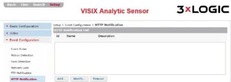
Figure 7-40: Setup Tab – Event Configuraon Menu – HTTP Nocation Sengs
2). From the HTTP Noficaons sengs page, a user may Add, Modify or Remove an HTTP web server for receiving event nocaons.
3). To remove an exisng HTTP server, select the server from the list and click Remove. You will be prompted to conrm.
4). Click OK to conrm the removal.
ADD/MODIFY AN HTTP SERVER
Steps:
1). To add an HTTP web server, click the Add... buon (if modifying, select the desired schedule HTTP server from the list and click Modify...). The Add to/Modify HTTP Nocaon List form will deploy.

Figure 7-41: Setup Tab – Event Configuraon Menu – HTTP Nocations – Adding/Modifying an HTTP Server
| HTTP Nocaon Seng | Descripon |
| Name | Name the HTTP server. This name will be used to identify this parcular HTTP server when assigning it to an e-mail nocaaon. |
| Descripon | Enter a descripon for the HTTP server. This will be displayed when the HTTP server is selected on the HTTP Nocaon sengs window. |
| IP Address/Port | Enter network conncon values for the desired HTTP Server. |
| Account / Password | Enter the user login credenals for the HTTP server. 3xLOGIC recommends using an administrave level account when possible to avoid permissions conicts. |
| Message | Enter a customized message to include with the nocaaon. |
| Append Detailed Informaon | Enable this checkbox to append detailed informaon including event details, the custom Message eld, etc... |
2). Click Test to test for a successful conncon with the dened HTTP web server. Once you have congured your desired sengs.
3). Click OK to save the newly congured HTTP web server.
TCP NOTIFICATIONS
Steps:
1). Opening the Setup Tab>Event Conguraon drop-down menu and clicking the TCP Nocaon link will open the TCP Nocation sengs page.

Figure 7-42: Setup Tab-Event Configuraon Menu – TCP Nocaon Sengs
2). From the TCP Nocations sengs form, a user may congregate the following sengs:
| TCP Nocaon Seng | Descripon |
| IP Address / Port | Enter TCP nocaaon's desnaon network conncon info. |
| Connect Timeout | Congure the conncon meout value. |
| Send Timeout | Congure the Send Timeout value. |
| Alive Type | Congure the TCP keep-alive packet mode. |
| Alive Time | Congure the me interval between keep-alive retransmissions. |
3). Click Apply to save changes to the TCP Nocaon sengs.
TCP SERVER
Steps:
1). Opening the Setup Tab>Event Conguraon drop-down menu and clicking the TCP Server link will open the TCP Server sengs page.
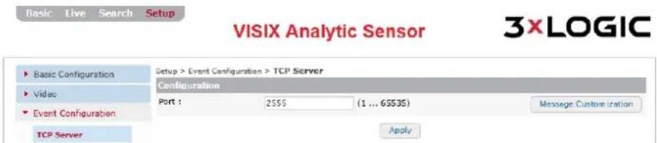
Figure 7-43: Setup Tab – Event Configuraon Menu - TCP Server Setngs
2). From the TCP Server seng pages, a user may enter a Port value for the TCP Event Server. Click the Message Customizaon buon to deploy the event message sengs for TCP Event servers.
| TCP Message Sengs | Descripon |
| Message Header Tab | Enable and customize a custom message header. |
| VCA Tab | Select a default message or congregate a custom message for VCA Cong, VCA Alarm and VCA Counter events. |
| MD Tab | Select a default message or custom message for moon detecon events. |
| Network Tab | Select a default message or congregate a custom message for Network events. |
| DI/DO Tab | Select a default message or congregate a custom message for DI/DO events. |
3). Click Apply to save changes to the TCP Server sengs.
MULTICAST NOTIFICATION
Steps:
1). Opening the Setup Tab>Event Conguraon drop-down menu and clicking the Mulcast Nocaon link will open the Mulcast Nocaon sengs page.

VISIX Analytic Sensor


Figure 7-44: Setup Tab – Event Conguraon Menu – Mulcast Nocaon Sengs
2). From the Mulcast Nocaon seng pages, a user may conjure the following UDP mulcast sengs:
| Mulcast Nocaon Sengs | Descripon |
| Address | Enter the UDP mulcast nocaon desnaon's IP address. |
| Port | Enter the UDP mulcast nocaon desnaon's enter the Port. |
| TTL | Set the TTL threshold.The TTL threshold is a me value which delineates how long a data packet can exist across an informaon network (local intranet, internet, etc...) before being invalidated.Approximaon of TTL threshold value eects are listed below:0 - Restricted to the same host. Won't be output by any interface.1 - Restricted to the same subnet. Won't be forwarded by a router.<32 - Restricted to the same site, organizaon or department.<64 - Restricted to the same region.<128 - Restricted to the same connent.<255 - Unrestricted in scope; Global. |
7.4 Network Conguraon Menu
TCP/IP SETTING
Steps:
1). Opening the Setup Tab>Network Conguraon drop-down menu and clicking the TCP/IP link will open the network TCP/IP sengs page.

Figure 7-45: Setup Tab – Network Conguraon Menu – TCP/IP Sengs
2). From the TCP/IP sengs page, a user may edit a camera's TCP/IP sengs. This includes all congorable sengs from the Basic Tab>Camera Conguraon> Network sengs (IP Sengs, DNS Server sengs pages as well as the ability to enable IPv6 and congrure host name and local link address details). These sengs can also be accessed via the Advanced Tab>Basic Conguraon Menu>Network Sengs.
| Network Seng | Descripon |
| IP Address Conguraon | Select the method by which the cameras will obtain an IP address:Obtain an IP Address via DHCP – Select this method to have your router’s DHCP funcon automacally assign the camera’s network conncon sengs. This method is enabled by default. The automacally-generated IP, Subnet Mask and Gateway addresses will be listed directly underneath.Use the following IP Address (Manual Conguraon) – Select this opon to manually enter network conncon sengs. IP Address, Subnet Mask and Gateway Addresses can be manually entered directly underneath this seng. Clicking the Test buon will conrm the validity of the network conncon addresses you have entered.ii. To enable IPv6 protocol, click Enable IPv6. For more information on IPv6 sengs, seeIPv6 Sengs Conguraon, below. |
| DNS Conguraon | Enter in Primary and Secondary DNS Server conneccon informaon. |
| Host Conguraon | Congure the device host name. |
| Link – Local Address | Checking-o Enable Auto-Conguraon Link-Local Address will generate an alternate internal IP address which can also be used to connect to the camera, access the UI via browser, etc.... when on the same network as the camera. |
NETWORK CONFIGURATION MENU - TCP/IP SETTINGS - IPV6 SETTINGS CONFIGURATION
Steps:
1). When the enable IPv6 box is checked, IPv6 sengs elds will deploy (pictured below).

Figure 7-46: Setup Tab – Network Conguraon Menu – TCP/IP Sengs – IPv6 Sengs
| IPv6 Seng | Descripon |
| Enable Accept Router Adversements | Enable Accept Router Adversements will allow the camera to accept router adversements, signaling device availability and connecvity to the host router. |
| Enable DHCP | Enable DHCP for automac IP address assignment. Select a DHCP Type from the drop-down menu. |
| IP Address | The device IP address. If DHCP is not enabled, the user may assign an address. |
| Prex Length | Assign an address prex length. |
| Default Router | Enter the default router address. |
WEB SERVER SETTINGS
Steps:
1). Opening the Setup Tab>Network Conguraon drop-down menu and clicking the TCP/IP link will open the network TCP/IP sengs page.
Basic Live Search Setup
VISIX Analytic Sensor
3xLOGIC

Figure 7-47: Setup Tab – Network Conguraon Menu – Web Server Sengs
2). From the Web Server sengs form, a user may congregate the camera's web server connconc sengs. Congurable sengs include choosing the hypertext protocol (HTTP or HTTPS), assigning separate port numbers for each protocol and choosing the Authencaon Type (basic or digest) for the acve protocol.
3). Click Apply to save any new changes to the Web Server sengs.
NTP SETTINGS
Steps:
1). Opening the Setup Tab>Network Conguraon drop-down menu and clicking the NTP link will open the network NTP sengs page.
Basic Live Search Setup
VISIX Analytic Sensor
3xLOGIC
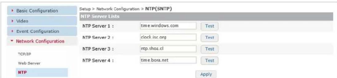
Figure 7-48: Setup Tab – Network Conguraon Menu – NTP Sengs
2). From the NTP sengs page, a user may enter NTP server conneccon info for me synchronizaon purposes. Up to four NTP servers can be added.
3). Aer entering a me server address, click the Test buon to conrm a conncon between the camera and the selected NTP Server. If the test fails, conrm you have entered in the correct address for the NTP Server.
4). Click Apply to save sengs changes.
UPNP SETTINGS
Steps:
1). Opening the Setup Tab>Network Conguraon drop-down menu and clicking the UPnP link will open the network UPnP sengs page.

VISIX Analytic Sensor


Figure 7-49: Setup Tab – Network Conguraon Menu – UPnP Sengs
2). From the UPnP sengs page a user may enable UPnP. UPnP (Universal Plug and Play) is a set of networking protocols that permits networked devices mobile devices to seamlessly discover each other's presence on the network and establish functional network services for data sharing, communicaons, and entertainment. UPnP is intended primarily for residential networks without enterprise-class devices.
3). Check-o the Enable box to enable UPnP. A user may also enter a device name. The camera model number will be used as the default name.
4). Click Apply to save changes to UPnP sengs.
RTSP/RTP SETTINGS
Steps:
1). Opening the Setup Tab>Network Conguraon drop-down menu and clicking the RTSP link will open the network RTSP sengs page.
RTSP CONFIGURATION

Figure 7-50: Setup Tab – Network Conguraon Menu – RTSP/RTP Seings – RTSP Conguraon
Steps:
1). Under the RTSP Configuraon secon of the RTSP sengs page, a user may congure an RTSP port (default is 554). The user may also enable and choose the RTSP Authencaon Type (digest or basic).
SRTP

Figure 7-50: Setup Tab – Network Conguraon Menu – RTSP/RTP Seings – SRTP Conguraon
Steps:
1). Under the SRTP (Secure RTP) Conguraon secon of the RTSP sengs page, a user may enable SRTP, a Protecon Prole type may be chosen and Master and Salt keys may be generated.
UNICAST

Figure 7-51: Setup Tab – Network Conguraon Menu – RTSP/RTP Seings – Unicast Conguraon
Steps:
1). Under the Unicast secon of the RTSP sengs page, a user may enable and congure Unicast sengs for the camera's First (Main) and Second (Sub) streams. Before conguring, make sure the desired stream tab has been selected (above the Unicast secon header).
| Unicast Seng | Descripon |
| Name | Name the unicast stream. |
| Enable Metadata | Check-o this box to include metadata with the stream transmission. |
| Enable ONVIF Metadata | Check-o this box to include ONVIF metadata with the stream transmission. |
| Enable QoS DSCP | Enable Quality of Service dierenated services. |
| Video / Meta / ONVIF Meta DSCP | Assign DSCP levels for Video, Meta and ONVIF Meta. Low-latency services will be dedicated starng with components featuring the highest DSCP value. |
MULTICAST

Figure 7-52: Setup Tab – Network Conguraon Menu – RTSP/RTP Seings – Mulcast Conguraon
Steps:
1). Under the Mulcast secon of the RTSP sengs page, a user may enable and congure Mulcast sengs for the camera's First (Main) and Second (Sub) streams. Before conguring, make sure the desired stream tab has been selected (above the Unicast secon header). Congurable sengs include:
| Mulcast Seng | Descripon |
| Enable Always Mulcast | Enabling this opon will have the selected stream use UDP mulcast indenitely for RTSP streaming. |
| Video IP Address/Port | Enter a stac address (or leave blank for auto conguraon) for broadcast of UDP Mulcast video. |
| Meta IP Address/Port | Enter a stac address (or leave blank for auto conguraon) for broadcast of UDP Mulcast meta data. |
| ONVIF Meta IP Address/Port | Enter a stac address (or leave blank for auto conguraon) for broadcast of UDP Mulcast ONVIF meta data. |
| TTL | Set the TTL threshold.The TTL threshold is a me value which delineates how long a data packet can exist across an informaon network (local intranet, internet, etc...) before becoming invalidated. Approximaon of TTL threshold value eects are listed below:0 - Restricted to the same host. Won't be output by any interface.1 - Restricted to the same subnet. Won't be forwarded by a router.<32 - Restricted to the same site, organizaon or department.<64 - Restricted to the same region.<128 - Restricted to the same connent.<255 - Unrestricted in scope; Global. |
| Name | Name the mulcast stream. |
| Enable QoS DSCP | Enable Quality of Service dierenated services. |
| Video / Meta / ONVIF Meta DSCP | Assign DSCP levels for Video, Meta and ONVIF Meta. Low-latency services will be dedicated starng with components featuring the highest DSCP value. |
RTMP SETTINGS
Steps:
1). Opening the Setup Tab>Network Conguraon drop-down menu and clicking the RTMP link will open the network RTMP sengs page.

Figure 7-53: Setup Tab – Network Conguraon Menu – RTMP Seings
2). From the RTMP Seings page, a user may enable RTMP. Real Time Messaging Protocol (RTMP) was initially a proprietary protocol developed by Macromedia for streaming audio, video and data over the Internet, between a Flash player and a server. V-Series All-in-One cameras can broadcast either of their stream proles using RTMP.
3). Check-o the Enable box to initiate RTMP streaming. The user may name the RTMP Name and Instance for both rst and second streams. RTMP streaming URL for both stream proles will be displayed.
4). Click Apply to save RTMP sengs changes.
MDNS SETTINGS
Steps:
1). Opening the Setup Tab>Network Conguraon drop-down menu and clicking the mDNS link will open the network mDNS sengs page.

Figure 7-54: Setup Tab – Network Conguraon Menu – mDNS Sengs
NOTE:
The mulcast Domain Name System (mDNS) resolves host names to IP addresses within small networks that do not include a local name server. It is a zero-conguraon service, using essenally the same programming interfaces, packet formats and operang semancs as the unicast Domain Name System (DNS).
2). From the mDNS sengs page, a user may check-o Enable to enable mDNS for this camera and assign a device Name. Click Apply to save sengs changes.
WS-DISCOVERY SETTINGS
Steps:
1). Opening the Setup Tab>Network Conguraon drop-down menu and clicking the WS Discovery link will open the network WS Discover sengs page.
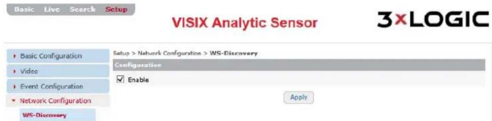
Figure 7-55: Setup Tab – Network Conguraon Menu – WS-Discovery Sengs
2). Check-o the Enable box to enable WS Discovery (Web Services Dynamic Discovery).
3). Click Apply to save sengs changes.
SMTP (E-MAIL SERVER) SETTINGS
Steps:
1). Opening the Setup Tab>Network Conguraon drop-down menu and clicking the SMTP link will open the network SMTP sengs page.

Figure 7-56: Setup Tab – Network Conguraon Menu – SMTP Sengs
2). From the SMTP sengs page, a user may congure e-mail server sengs. SMTP sengs must be congured correctly to allow for the successful transmission of event e-mail nocaoons. Congurable sengs include:
| SMTP Seng Category | Descripon |
| E-Mail Sender | Congure aSender Name(to be displayed in theFromemail eld) andFrom Email Address. |
| SMTP | Congure the SMTP Mail Server Address and Port.Check-oEnable Encrypted Connecon (SSL) to enable SSL encrypon of e-mails sent through the congured SMTP Server.Check-oUse Authencaon to Log In This Serverto require login when |
| Test | Congure a test email. Enter the test recipient address and click the Testbuon to conrm successful SMTP conguraon. |
3). Click Apply to save changes to SMTP sengs.
DDNS SETTINGS
Steps:
1). Opening the Setup Tab>Network Conguraon drop-down menu and clicking the DDNS link will open the network DDNS sengs page.

Figure 7-57: Setup Tab – Network Conguraon Menu – DDNS Seings
2). From the DDNS (Dynamic Domain Name System) sengs page, a user may enable DDNS and congure related sengs. Available congorable sengs include:
| DDNS Seng | Descripon |
| Service Provider | Choose the DDNS service provider (DynDNS.org, FreeDNS.org, NO-IP.com) |
| Domain Name | Congure a domain name for use with the DDNS service. |
| Update Time | Congure a DDNS update interval (in seconds). |
| Username and Password | Congure login credenals if required. Field availability is dependent on chosen DDNS service provider. |
3). Click Apply to save DDNS sengs changes.
SNMP SETTINGS
Steps:
1). Opening the Setup Tab>Network Conguraon drop-down menu and clicking the SNMP link will open the network SNMP sengs page.

Figure 7-58: Setup Tab – Network Conguraon Menu – SNMP Sengs
NOTE:
SNMP (Simple Network Management Protocol) is an Internet-standard protocol for collecting and organizing informaon about managed devices on IP networks and for modifying that informaon to change device behavior.
2). From the SNMP sengs page, a user may Enable SNMP and conjure the following related sengs:
| SNMP Seng Category | Descripon |
| SMNP Version | Select the SMNP version to use with the camera. |
| SMNP Descripon | Congure SMNP Locaon and Contact descripon informaon. |
| VACM Seng | Congure the View-based Access Control Model Read Community.The camera default sengs is public (read-only). Private (read-write) can also be used. |
| Trap Seng | Dene an Address and Community for Trap Ver 1.0 and 2.0. |
3). Click Apply to save SNMP sengs changes.
IP FILTERING SETTINGS
Steps:
1). Opening the Setup Tab>Network Conguraon drop-down menu and clicking the IP Filtering link will open the network IP Filtering sengs page.

Figure 7-59: Setup Tab – Network Conguraon Menu – IP Filtering Sengs
NOTE:
IP Filtering is a simple process which essenally decides which types of IP datagrams will be processed using normal procedures and which will be discarded/ignored.
2). From the IP Filtering sengs page, a user may enable IP Itering and conjure the following related sengs.
| IP Filtering Seng | Descripon |
| Always Allow Ping Request | If enabled, the camera will accept pings, regardless if the incoming ping is sent from a device with a Itered IP address. |
| Allow/Deny | Set the IP Filtering Mode to Allow or Deny. Based on your choice, addresses in the Filtered IP Addresses list will be denied or allowed. |
| Add.../Remove | Select the Add... buon to add an IP address for Itering. Enter an IP Address and click OK to save the new address.To remove an exisng address from the Itered list, select the address in the list and click Remove. You will be prompted to conrm the removal. Click OK to conrm. |
3). Click Apply to save changes to IP Filtering sengs.
HOSTED SERVICE SETTINGS
Steps:
1). Opening the Setup Tab>Network Conguraon drop-down menu and clicking the Hosted Service link will open the Hosted Service sengs page.

VISIX Analytic Sensor

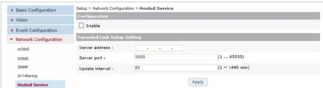
Figure 7-60: Setup Tab – Network Conguraon Menu – Hosted Service Sengs
2). From the Hosted Service sengs page, a user may enable congregate connecon sengs for camera integraon with a hosted service. Available congorable sengs include:
| Hosted Service Sengs | Descripon |
| Server Address and Port | Enter the hosted service IP Address and Port. |
| Update Interval | Enter an update interval (in minutes) |
3). Click Apply to save hosted service sengs.
7.5 Storage Menu
SD SETTINGS
Steps:
1). Opening the Setup Tab>Storage drop-down menu and clicking the SD link will open the SD sengs page.

Figure 7-61: Setup Tab -Storage Menu - SD Seings
2). From the SD Card storage sengs page, a user may choose their SD storage device, view informaon on the chosen device, change storage format or mount and eject storage devices. These sengs can also be accessed from Basic Tab>Storage Conguraon Menu>SD.
SD STORAGE LIST
In the SD Storage List secon, a user may select their desired storage device from the list. The following device details will be generated to the right of the device list aer making a selecon:
| Storage Detail | Descripon |
| Disk | The storage device disk type of the selected device. |
| Type | The storage disk format of the selected device. |
| Total Capacity | The totally storage capacity of the selected device. |
| Free Space | Lists the remaining free space on the selected device. |
| Status | Current storage device status. |
RECORDING DEVICE CONTROL
In the Record Device Control secon, a user may select the desired storage format (vfat, ext3) and can also mount an inactive storage device or eject the currently active storage device:
| Device Control | Descripon |
| Format (vfat) | Use vfat format for the selected device. Format progress will be displayed.WARNING: Re-formang the storage device will wipe all stored footage. Download any footage you wish to retain before beginning the format process. |
| Format (ext3) | Use ext3 format for the selected device. Format progress will be displayed.WARNING: Re-formang the storage device will wipe all stored footage. Download any footage you wish to retain before beginning the format process. |
| Mount | Mount the currently selected device. This opon is only available if the currently selected device is inactive. |
| Eject | Eject the currently selected device. This opon is only available if the selected device is mounted. |
FTP SETTINGS
Steps:
1). Opening the Setup Tab>Storage drop-down menu and clicking the FTP link will open the FTP storage sengs page.

Figure 7-62: Setup Tab -Storage Menu -FTP Sengs
2). If uploading footage data to an FTP desnaon is desired, a user may congregate connecos sengs from for their desired FTP service on the FTP Sengs page.
| FTP Seng | Descripon |
| Name | Name the FTP server. This name will be used to identify this parcular FTP when selecng it for storage purposes. |
| IP Address/Port | Enter network conncon values for the desired FTP Server. |
| Target Directory | Enter the target desnaon directory on the FTP for storing uploaded les. |
| Account / Password | Enter the user login credenals for the FTP. 3xLOGIC recommends using an administrave level account when possible to avoid permissions conicts. |
| Filename Format | Assign the lename format for the les uploaded to the FTP. |
3). Click Apply to save changes to FTP storage sengs.
RECORDING
Steps:
1). Opening the Setup Tab>Storage drop-down menu and clicking the Recording link will open the Recording storage sengs page.

Figure 7-63: Setup Tab -Storage Menu -Recording Sengs
2). From the Recording sengs page, a user may conjure sengs related to the cameras recording funconality.
Congurable recording sengs include:
| Recording Seng Category | Descripon |
| Recording Type | Select a recording mode for the cameras. The following modes are:■ Connuous – Select Connuous recording mode to have the camera constantly record.■ Event - Select Event recording mode to have the camera begin recording based on an events (i.e. moon detecon, VCA tripwire, DIO etc...).■ None – Select the None mode to use the camera as a live-view only device. |
| Recording Storage Opons | Select a storage device from the drop-down menu.If Connuous is selected as the Recording Type, the user must select the storage Recycling mode. Choose Stop Recording to halt recording when storage is at full capacity.Choose Delete Files and Recycle (Oldest First) to connue recording and overwrite the oldest les on the storage device when storage has reached full capacity. |
| Recording Sengs (With Event Recording Type) | Recording Resource - Select recording resources. Choose from Video, Audio (for audio-capable camera models only), VCA Meta Data and Moon Detecon (MD) Meta Data. Chosen resources will be captured when recording. Specify the length of me the camera will connue to record aer a trigger has been deactivated by seng a Recording Hold O Time value (seconds). A maximum of one minute (60 seconds) can be congured. Select the recording Stream Source (First/Main Stream, Second/Substream).from the available drop-down menu. |
| Recording Sengs (With Connuous Recording Type) | Filename Prex – Designate a lename prex for connuous recording les.Recording Resource - Select recording resources. Video Only is the recommended (and default) seng to maximize storage ulizaon.Select the maximum connuous Recording File size/Duraon by selecng and adjusng the Size or Time slider accordingly. When the maximum limit is reached, a new le will begin recording and the current le will be available for download from the Connuous storage page. Select the recording Stream Source (First/Main Stream, Second/Substream).from the available drop-down menu. |
| Instant Recording (Connuous Recording Type Only) | Congure an Instant Recording me interval (in seconds). Use this feature to quickly create a footage le without waing unl the congured Maximum Filesize/Duraon is reached.Click Start to end the current le and begin recording a new le for the length you have congured. |
3). Click Apply to save Recording sengs changes.
CONTINUOUS (RECORDING) SETTINGS
Steps:
1). Opening the Setup Tab>Storage drop-down menu and clicking the Connuous link will open the Connuous storage sengs page.

VISIX Analytic Sensor

![Setup > Storage > Continuous Num FileName DataTime Size Download 1 REC-C20151214-101228-0000000073.avi 12/14/2015 10:12:28 220.8M [Recording] 2 REC-C20151214-093447-0000000072.avi 12/14/2015 09:34:47 496.0M [Download] 3 REC-C20151214-085712-0000000071.avi 12/14/2015 08:57:12 496.1M [Download] 4 REC-C20151214-081744-0000000070.avi 12/14/2015 08:17:44 496.4M [Download] 5 REC-C20151214-073742-0000000069.avi 12/14/2015 07:37:42 496.2M [Download] 6 REC-C20151214-065727-0000000068.avi 12/14/2015 06:57:27 496.2M [Download] 7 REC-C20151214-061713-0000000067.avi 12/14/2015 06:17:13 496.1M [Download] 8 REC-C20151214-053648-0000000066.avi 12/14/2015 05:36:48 496.2M [Download] 9 REC-C20151214-045634-0000000065.avi 12/14/2015 04:56:34 496.3M [Download] 10 REC-C20151214-041622-0000000064.avi 12/14/2015 04:16:22 496.3M [Download] 11 REC-C20151214-033617-0000000063.avi 12/14/2015 03:36:17 496.2M [Download] 12 REC-C20151214-025613-0000000062.avi 12/14/2015 02:56:13 496.0M [Download] 13 REC-C20151214-021613-0000000061.avi 12/14/2015 02:16:13 496.3M [Download]](/content/2026/06/1400889/images/5476c14d1d4aa126cf681b59b28c5bea5e7951f41942b063cc2257b3195a3129.jpg)
Figure 7-64: Setup Tab -Storage Menu -Connuous (Recording) Sengs
2). From the Connuous storage sengs page, a user may access any les recorded using Connuous recording type. File info including File Name, Date/Time range, and Size (in MB) will be displayed for each available le. If a le is currently being recorded, it will display as Recording under the Download column.
3). To download an available le, simply click the corresponding Download link.
4). Use the navigaon controls at the boom of the le list to navigate mulple pages of les.
NOTE:
Connuous footage les can only be accessed (downloaded) from this page and cannot be viewed via the Search (Playback tab).
7.6 VCA Menu
ENABLE/DISABLE
Steps:
1). Opening the Setup Tab>VCA drop-down menu and clicking the Enable/Disable link will open the VCA Enable/Disable sengs page.

VISIX Analytic Sensor


Figure 7-65: Setup Tab –VCA Menu –Enable/Disable Sengs
2). From the VCA Enable/Disable sengs page, a user may enable VCA and conjure the following sengs:
| VCA Seng | Descripon |
| VCA Features | Enable desired VCA features:Object Tracking- Enable this funcon to use the Object Tracking analyc.Object tracking analycs are generally utilized to count queue mes, trigger no-customer present excepons, etc...Counng Line- Enable this funcon to use the Counng Line analyc.Counng Line/Tripwire analycs are generally used to count objects entering/exing a space. |
| Tracking Mode | Choose the VCA tracking mode.Surveillance– Surveillance tracking mode should be used for intruder detecon or outdoor surveillance.People– People tracking mode is most suitable for tracking mulple people in indoor, high trac environments. People tracking requires an advanced All-in-One Analycs license. |
3). To restore VCA Enable/Disable sengs to their factory default state, click Restore Defaults
4). Click Apply to save sengs changes.
ZONES AND RULES SETTINGS
Steps:
1). Opening the Setup Tab>VCA drop-down menu and clicking the Zones and Rules link will open the VCA Zones and Rules sengs page.
2). From the VCA Zones and Rules page, a user may perform the majority of VCA analycs conguraons. The Zones and Rules sengs page consists of two separate tabs. The Zones & Rules tab and the Logical Rules tab. By default, the page will open with the Zones & Rules tab deployed.
ZONES AND RULES SETTINGS – ZONES & RULES TAB
Steps:
1). On the Zones and Rules tab, Zones, Lines and Counters (and the analycs Rules pertaining to each) can all be constructed or placed within the live preview image.

Figure 7-66: Setup Tab –VCA Menu –Zones and Rules Seings – Zones & Rules Tab
2). The Zones & Rules tab consists of three segments:
i. Preview Area – A live preview of the camera's image. In the preview area, user may overlay analycs Zones, Lines and Counters for use with the analycs engine.
ii. Zone and Rule List – Recent object interacon with zones/lines will be listed in this area with the following informaon provided for each entry: ID, Rule Name, Zone Name, Object Type, Start Time, and End Time.
iii. Rule Conguraon Menu - When a zone, line or counter is selected, rule opons pertaining to the selected elements funconality will be available for conguraon in this menu. When no item is acvely selected, this secon will display all zones/lines and counters currently congured on the device (as pictured in the above example).
3). To create analytics rules or zones, right-click within the preview area.
The following menu opons will be available:
| Right-Click Opon | Descripon |
| Zone/Line | Create Zone – Create an analycs zone. Zones are oen used for queue wait and dwell mers.Create Line – Create an analycs line/tripwire. Lines are generally used for people counng.Remove All Zones and Lines – Remove all acve zones and line. |
| Counter | Add Counter – Create a counter. Counters can be used to tally present objects in a dwell zone.Reset All Counters – Reset all acve counters to zero.Remove All Counters – Remove all counters from the overlay. |
| Display | Display Blobs – Display moon blob. This opon is generally used for visual diagnoses and is only available when Blob has beenDisplays Objects – From this men, the user may enable several object display opons. Opons include:■ Display Objects –Track objects on-screen. ■ Display Objects in Mulple Colors – Use diering colors for object trackers when mulple objects are present. ■ Display Non-Alarmed Objects – Display objects which are not currently triggering an alarm/event (Object detected in eld of visions but does not enter dwell zone/ cross counng line). ■ Display Object Speed – Display the object speed value.Display System Messages – Display analycs system messages generated by the camera on-screen. |
| Pause | Pause the live video preview on the current frame. |
CREATE ZONE
Steps:
1). To create a zone, right-click within the preview area and select Zone/Line>Create Zone.
2). Draw the zone within the preview area as desired by clicking and dragging each corner until a satisfactory shape and posion is achieved.
Figure 7-67: Setup Tab –VCA Menu –Zones and Rules Sengs – Creang a Zone
3). When a zone is selected, the following opons will be available in the Rule Conguraon Menu:
Name
Name the zone. This name will be used to refer to this parcular zone throughout the cameras browser interface.
Color
Assign a color to the zone. This will allow for fast visual recognition when mulple zones are present.
Select the zone's detection mode.
- Detect- Detect object moon within the analycs zone.
Non-Detect -Cease detecting objects within the camera's eld of vision when they enter the analycs zone. Non-Detect zones are oen ulized as a mask.
Detect/Non-Detect
| VCA Zone – Rule Cong. | Descripon |
| Object Class Filter | Create an Object Filter. Object Iters can be used to Iter predened objects from triggering an analycs event. Filters can also be congured to trigger an event ONLY when a specic object class is detected within a zone.Include/Exclude – Select Include to apply analycs only to objects of the selected classicaon. Select Exclude to exclude objects of the selected classicaon from triggering analycs events.To create an Object Class Filter, check o a Iter and choose the object class in the Value eld drop-down (Filter 0 is acvely Itering the Cluer object class in the below example). For informaon on conguring object classes, see Classicaon Sengs. For informaon on conguring object classes, see Classicaon Sengs. |
| Presence | Enable this rule to trigger an analycs event whenever an object comes into contact with any poron of the zone. The zone will remain triggered so long is presence is detected. |
| Enter | Enable this rule to trigger an analycs event whenever an object enters the zone. |
| Exit | Enable this rule to trigger tan analycs event whenever an object exits the zone. |
| Appear | Enable this rule to trigger an analycs event whenever an object appears within the zone. |
| Disappear | Enable this rule to trigger an analycs event whenever an object disappears from the zone. |
| Stopped | Enable this rule to trigger an analycs event whenever an object has stopped moving within the analycs zone for equal to or longer than the dened Time (Seconds). |
| Dwell | Enable this rule to trigger an analycs event whenever an object has dwelled within the zone longer than the dened Threshold (Seconds). |
| Direcon Filter | Enable this rule to trigger analyc events based on direconal movement through the zone. A direconal indicator will be overlaid over the zone. Adjust the Direcon and Acceptance angle to congure a direcon spectrum. Only objects travelling through the zone within this direconal spectrum will trigger an analycs event. |
| Speed Filter | Enable this rule to trigger an analycs events whenever an object travels through the zone within the dened speed rangeCongure a Lower Bound (km/h) and Upper Bound (km/h) speed value to denote your speed range. |
| Tailgang | Enable this rule to trigger an analycs event whenever an object enters the zone within the dened Time (Seconds) period aer another object has entered.If the Time (Seconds) value is set to 5, then anymore an object enters a zone within 5 seconds of another object, the camera will consider this tailgang and an analycs event will be triggered. |
| Color Filter | Enable this rule to trigger an analycs event whenever an object of a specied color is detected within the zone.Set a Threshold (%) to designate how much of an object must feature the specied color to trigger the alarm. If the Color is set to Blue, and the Threshold is set to 25%, than an object which is 25% blue or more will trigger an analycs event. |
4). Right-clicking a zone within the preview area will deploy a menu with the following opons:
| VCA Zone – Right-Click Opon | Descripon |
| Remove Zone | Remove the zone from the live preview. All rules associated with the zone will be deleted. |
| Insert/Remove Node | Insert/Remove a node to the zone border. Adding nodes will allow the user to further customize the shape of the zone. |
| Rules | Enable a rule. If a secondary seng for a rule exists (Dwell, Direconal Filter, etc...) default values for the secondary sengs will be used. |
| Pause | Pause the live video preview on the current frame. |
5). Click the Apply buon to save your new VCA Zone sengs.
CREATE LINE (TRIPWIRE)
Steps:
1). To create a line, right-click within the preview area and select Zone/Line>Create Line.
2). Draw the line within the preview area as desired by clicking and dragging to place both line endpoints.

Figure 7-68: Setup Tab –VCA Menu –Zones and Rules Seings – Creang a Line
3). When a line is selected, the following opons will be available in the Rule Conguraon Menu:
| VCA Line – Rule Cong. | Descripon |
| Name | Name the line. This name will be used to refer to this parcular line throughout the cameras browser interface. |
| Color | Assign a color to the line. This will allow for fast visual recognition when mulple zones/lines are present. |
| Object Class Filter | Create anObject Filter.Object Iters can be used to Iter predened objects from triggering an analycs event. Filters can also be congured to trigger an event ONLY when a specic object class has contacted the line.Include/Exclude – SelectIncludeto trigger an event with only objects of the selected classicaon. SelectExcludeto exclude objects of the selected classicaon from triggering analycs events.To create anObject Class Filter, check o a lter and choose the object class in theValueeld drop-down (Filter 0 is acvelyitering theCluerobject class in the below example). For informaon on conguring object classes, seeClassicaonSengs. For informaon on conguring object classes, seeClassicaonSengs. |
| Presence | Enable this rule to trigger an analycs event whenever an object comes into contact with any poron of the line. The line will remain triggered so long as contact is maintained between the line and the object. |
| Enter | Enable this rule to trigger an analycs event whenever an object contacts the line. |
| Exit | Enable this rule to trigger tan analycs event whenever an object ceases contact with the line. |
| Appear | Enable this rule to trigger an analycs event whenever an object is detected and is already in contact with the line. This rule is generally reserved for use with zones and is not recommended for lines. |
| Disappear | Enable this rule to trigger an analycs event whenever the camera ceases tracking an object which was in contact with the line before tracking ceased. This rule is generally reserved for use with zones and is not recommended for use with lines (tripwires). |
| Stopped | Enable this rule to trigger an analycs event whenever an object has stopped moving on the line for equal or greater than thedened amount ofTime(Seconds). |
| Dwell | Enable this rule to trigger an analycs event whenever an object has dwelled on the line longer than the dened Threshold (Seconds). This rule is generally reserved for zones and funcons similarly to the Stopped rule when used with a line. |
| Direcon Filter | Enable this rule to trigger analyc events based on direconal movement across the line. A direconal indicator will be overlaid over the line. Adjust the Direcon and Acceptance angle to congure a direcon spectrum. Only objects travelling across the line within this direconal spectrum will trigger an analycs event. This rule is generally reserved for use with zones, and funcons similarly to the Coung Line rule (outlined below) when used with a Line (tripwire). |
| Speed Filter | Enable this rule to trigger an analycs events whenever an object travels through the zone within the dened speed rangeCongure a Lower Bound (km/h) and Upper Bound (km/h) speed value to dene your speed range. |
| Tailgang | Enable this rule to trigger an analycs event whenever an object enters the zone within the dened Time (Seconds) period aer another object has entered.If the Time (Seconds) value is set to 5, then anymore an object enters a zone within 5 seconds of another object, the camera will consider this tailgang and an analycs event will be triggered. |
| Coung Line | Enable this rule to trigger an analycs event whenever an object crosses the line in a chosen direcon.Direcons - Congure which direcons to monitor by selecngDirecon A, Direcon B, or both. An on-screen overlay will be visible to demonstrate which direcons correspond to A and B.Width Calibraon - Enable Width Calibraon to indicate the ancipated width of counted objects. An overlay will appear in the live preview, over the line. Small lines on either side show the minimum and maximum object widths. Use your mouse-wheel or click-and-drag the marker to change the width.Shadow Filter - Enable Shadow Filter to help migrate the possibility of shadows causing a false trigger. This technology ulizes light and color sensitivity to avoid detecon of shadows but does not guarantee false trigger prevenon. |
| Color Filter | Enable this rule to trigger an analycs event whenever an object of a specied color contacts the line.Set a Threshold (%) to designate how much of an object must feature the specied color to trigger the alarm. If the Color is set to Blue, and the Threshold is set to 25%, than an object which is 25% blue or more will trigger an analycs event. |
4). Right-clicking a line within the preview area will deploy a menu.
The opons are as followed:
| VCA Line- Right-Click Opon | Descripon |
| Remove Line | Remove the line from the live preview. All rules associated with the zone will be deleted. |
| Insert/Remove Node | Insert/Remove a node to the line to create another line segment. |
| Rules | Enable a rule. If a secondary seng for a rule exists (Dwell, Direconal Filter, etc...) default values for the secondary sengs will be used. |
| Pause | Pause the live video preview on the current frame. |
5). Click the Apply buon to save your new VCA Zone/Line sengs.
CREATE COUNTER
Steps:
1). To create a Counter, right-click within the preview area at the locaon you wish to overlay the counter and select Counter>Add Counter.

Figure 7-69: Setup Tab –VCA Menu –Zones and Rules Seings – Creang a Counter
2). When a counter is selected, the following opons will be available in the Rule Conguraon Menu:
| VCA Counter– Rule Cong | Descripon |
| Name | Name the counter. This name will be used to refer to this parcular line throughout the cameras browser interface and on the counter overlay itself. |
| Color | Assign a color to the counter. This will allow for fast visual recognition when mulple zones/lines/counters are present. |
| Increment | Enable Increment to increment the counter anymore a chosen analycs event occurs. Acvate the desired increment rule (Inc 0 used in the above example) and assign a rule trigger under the Value column (A counng line rule named Zone 0 –Cnt Line – Dir A is used in the above example). Acvate the desired increment rule (Inc 0 used in the above example) and assign a rule trigger under the Value column (A counng line rule named Zone 0 –Cnt Line – Dir A is used in the above example). |
| VCA Counter – Rule Cong. | Descripon |
| Decrement | Enable Decrement to decrement the counter anymore a chosen analycs event occurs. Acvate the desired increment rule (Dec 0 used in the above example) and assign a rule trigger under the Value column (A counting line rule named Zone 0 –Cnt Line – Dir A is used in the above example). Acvate the desired increment rule (Dec 0 used in the above example) and assign a rule trigger under the Value column (A counting line rule named Zone 0 –Cnt Line – Dir A is used in the above example). |
| Occupancy | Enable Occupancy to count occupants of a specied zone. Acvate the desired occupancy rule (Occ 0 used in the above example) and assign a rule trigger under the Value column (A zone presence rule named Zone 1 – Presence is used in the above example). Acvate the desired occupancy rule (Occ 0 used in the above example) and assign a rule trigger under the Value column (A zone presence rule named Zone 1 – Presence is used in the above example). |
3). Click the Apply buon to save your new VCA Counter sengs.
ZONES AND RULES SETTINGS – LOGICAL RULES TAB
From the Logical Rules tab, a user may set up further rules governed by a set of custom logical operators. Logical rules can be written in such a manner that they can run on a schedule; while other rules or events are active (or not active); when a digital input is received, etc. These Logical Rules can also be used to trigger the generation of events (alarms/DO); incrementing of custom counters, etc...
Steps:
1). To open the Logical Rules sengs tab, click the Logical Rules tab on the Setup (Advanced Tab)>VCA>Zones and Rules sengs page.
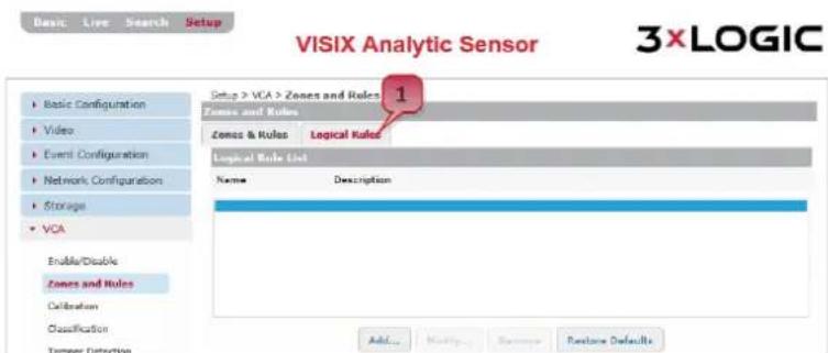
Figure 7-70: Setup Tab –VCA Menu –Zones and Rules Seings – Opening the Logical Rules Tab
2). From the Logical Rules sengs tab, a user may Add, Modify, or Remove a logical rule.
3). For instrucons on adding/modifying a logical rule, see Adding/Modifying a Logical Rule. To remove an existing logical rule, select the rule from the list and click Remove. You will be prompted to conrm the removal. Click OK to conrm.
ADDING/MODIFYING A LOGICAL RULE
Steps:
1). To add a logical rule, click the Add... buon. If modifying an exisng rule, select the rule from the list and click Modify... Both acons will cause the Add/Modify New Rule window to deploy.
![[2] Name: Rule Name Description: Rule Description Trigger the logical rule when the following condition is met: --Select clause type-- Run the following actions when the rule is triggered:](/content/2026/06/1400889/images/98ce1f52cd936a99c79b1de4ce7c8954fde547c378fdf2e4da1abbb513ea7ce5.jpg)
Figure 7-71: Setup Tab –VCA Menu –Zones and Rules Seings – Logical Rules Form
2). Assign a Name and Descripon to the rule by lling in the respective elds.
3). Under the Trigger the Logical Rule when the Following Condion is Met text, a user may select a condion clause. Some of these clauses will require secondary condional clauses to be chosen as well ([and], [or], etc...) Descripons of the available condion clauses are listed below:
| Logical Rule - Clause | Descripon |
| [rule] | Select this condional clause to trigger the logical rule whenever a VCA rule is true/acve. Select the condional trigger rule from the available drop-down. |
| [and] | Select this condional clause to trigger the logical rule whenever mulple clauses are simultaneously true/acve. Select the condional clause from the available drop-down. All chosen condional clauses must be true to trigger the logical rule. |
| [or] | Select this condional clause to trigger the logical rule whenever one of mulple clauses rules is true. Select each condional trigger rule from the drop-downs as necessary. Only one of the mulple congured rules must be triggered/acve to trigger the logical rule. |
| [not] | Select this condional clause to trigger when a specied clause is not true. |
| [connuously] | Select this condional clause to trigger the logical rule whenever a clause has been connuously true/false for a specied period of me. |
| [previous] | Select this condional clause to trigger the logical rule when a clause was previously true/false for a specied period of me. |
| [was] | Select this condional clause to trigger the logical rule when a clause was true/false a specied period of me ago. |
| [me] | Select this condional clause to trigger the logical rule during a specied daily me range. |
| Logical Rule – Clause | Descripon |
| [day] | Select this condional clause to trigger the logical rule on a specied day of the week. |
| [date] | Select this condional clause to trigger the logical rule on a specied date of the year. |
| [value] | Select this condional clause to trigger the logical rule whenever a VCA counter reaches a specied value. Select the desired Counter, operator (<, >, =) and specify a counter value in the available text eld. |
| [input] | Select this condional clause to trigger the logical rule whenever a digital input of your choosing is in a state (open, closed) of your choosing. Select the desired input and state from the available drop-down menus. |
| [before] | Select this condional clause to trigger the logical rule whenever a specied [and] condional clause occurs before another.NOTE: This clause is only available as a secondary condional clause within an [and] clause. |
| [identity] | Select this condional clause to trigger the logical rule whenever two specied clauses are each triggered by the same (or dierent; user specied) objects.NOTE: This clause is only available as a secondary condional clause within an [and] clause. |
| [within] | Select this condional clause to trigger the logical rule whenever two specied [and] condional clauses are each triggered within a specied amount of me of one another.NOTE: This clause is only available as a secondary condional clause within an [and] clause. |
| [classicaon] | Select this condional clause to trigger the logical rule whenever a specied [and] condional clause is triggered by an object of a specied class.NOTE: This clause is only available as a secondary condional clause within an [and] clause. |
| [between] | Select this condional clause to trigger the logical rule whenever a specied [and] condional clause is triggered between two specied mes. Select the desired clause and congregate the two mes using the available drop-down menus.NOTE: This clause is only available as a secondary condional clause within an [and] clause. |
| [tamper] | Select this condional clause to trigger the logical rule whenever tampering detected. See Tamper Detecon Sengs for more info on conguring tamper detecon. |
| [learning] | Select this condional clause to trigger the logical rule whenever a scene is being learned. |
4). Congure your condional trigger clause as desired. When you have congured the clause, the trigger acons must also be selected. The trigger acon is simply the resulting acon of the logical rule being triggered.
A list of available trigger acons is described below:
| Logical Rule - Acon | Descripon |
| [generateevents] | Select this acon to generate an event whenever the logical rule is triggered. |
| [incrementcounter] | Select this acon to increment a specied VCA counter whenever the logical rule is triggered. |
| [learnscene] | Select this acon to have the camera perform scene learning whenever the logical rule is triggered. |
| [resetcounter] | Select this acon to reset a specied VCA counter whenever the logical rule is triggered. |
5). Once you have congured both a condional clause and a trigger acon, click OK to save the new logical rule.
CALIBRATION SETTINGS
Steps:
1). Opening the Setup Tab>VCA drop-down menu and clicking the Calibraon link will open the network DDNS sengs page.

Figure 7-72: Setup Tab –VCA Menu –Calibration Sengs
2). The VCA calibraon process includes conguring the correct camera angle and eld of view, as well as the delineaon of ancipated object (people, car, etc...) size. Proper calibraon of the camera is required to ensure accurate analytics counts and tracking.
The following calibraon specicaons are available for conguraon:
| VCA Calibraon Spec | Descripon |
| Preset Select | Select a precongured preset. Presets include: Overhead, 60 Degree Lookdown, 30 Degree Lookdown. |
| Height | Adjust calibraon height. Use this to best emulate the height of the camera from the ground. Note the mimic size in comparison with an actual person to gain the best results. |
| Tilt Angle | Adjust calibraon lt angle. Use this to best emulate the camera's lt angle. |
| Vercal Field of View | Adjust the calibraon vercal eld-of-view. Use this to best emulate the camera's vercal perspecve. |
| Pan Angle | Adjust the calibraon roll angle. Use this to best emulate the camera's pan perspecve. |
| Roll Angle | Adjust the calibraon roll angle. Use this to best emulate the camera's pan perspecve. |
Steps:
1). To begin calibraon, adjust calibraon sengs as required. A user may perform basic calibraon cameras via two separate methods:
1). Click-and-Drag. - For this method, click and drag the green calibraon grid to sasfactorily emulate the camera's height, It perspective, and eld of view. The mimics may be moved around the image to help the user gauge perspective. The mouse scroll wheel is also ulized to adjust camera height, and consequently the size of the calibraon grid and mimics. Use resizing of these elements to anticipate average object size.
2). Manual Conguraon - Manually enter/adjust calibraon values under the Camera Setup secon. As the user enters values, the calibraon overlay on the live preview will react accordingly.
3). If required, adjust Pan Angle and Roll Angle under the Advanced Parameters secon using the slider bars. As the sliders are moved, the calibraon overlay over the preview image will react accordingly. Advanced Parameters must be manually entered and cannot be adjusted using the Click-and-Drag technique.
4). Right-click within the video preview area for the following calibraon tools:
| Right-Click Opon | Descripon |
| Virtual Ruler | Select this tool to anchor a virtual ruler from the point-of the right click. Drag your mouse across the image to extend the ruler. Use this feature to ensure accurate perspective calibraon sengs. |
| Draw Horizon | Select this opon to add a drawn horizon line to the calibraon grid. This horizon line will be visible when the camera's lt angle is twenty degrees or less. |
| Transparent Grid (enabled by default) | Select this opon to make the green calibraon grid transparent. |
| Add Mimic | Add another mimic to the live preview. |
| Pause | Pause the live preview image on the current frame. |
5). When you have calibrated the camera to your sasfacon, click Apply to save the new calibraon sengs.
6). If desired, click Uncalibrate to reset all calibraon specicaons to their default value.
CLASSIFICATION SETTINGS
Steps:
1). Opening the Setup Tab>VCA drop-down menu and clicking the Classification link will open the VCA object Classicaon sengs page.

Figure 7-72: Setup Tab -VCA Menu -Classicaon Sengs
2). From the Classification sengs page, a user may Add, Remove or modify an object classicaon. Four default classicaons exists: Cluer, Person, Group of People, and Vehicle.
3). To create a new classicaon, click the Add buon and conjure the required classier informaon. To modify an exisng classicaon, select it from the list and edit the classier informaon as required. Classier informaon is described below:
| Classier Info | Descripon |
| Name | Name the classicaon. |
| Enable | Enable the classicaon to have the camera acvely classify objects that meet the classicaon's parameters. If disabled, the camera will not classify objects with this class. |
| Min Area | The minimum area (in square meters) taken up by an object of this classicaon. |
| Max Area | The maximum area (in square meters) of an object of this classicaon. |
| Min. Speed | The minimum travelling speed (in km/h) of an object of this classicaon. |
| Max. Speed | The maximum travelling speed (in km/h) of an object of this classicaon. |
4). Click Apply to save the new classicaon sengs.
5). Click Restore Defaults to reset the classicaons to their default sengs. This will delete any custom classicaon.
TAMPER DETECTION SETTINGS
Steps:
1). Opening the Setup Tab>VCA drop-down menu and clicking the Tamper Detecon link will open the VCA object Tamper Detecon sengs page.

Figure 7-72: Setup Tab –VCA Menu –Tamper Detecon Setngs
2). From the Tamper Detecon sengs window, a user may enable Tamper Detect, and congure related sengs. Tamper Detecon safeguards the camera against vandalism or view obscuraon by generang an alarm whenever tampering is detected.
3). To acvate tamper detecon, check-o Enable.
The following tamper detecon sengs can be congured:
| Classier Info | Descripon |
| Tamper DuraonUnl Alarm | The amount of me allowed to transpire during tampering unl the tamper alarm is triggered. |
| Tamper Image Area | The amount of the image to use for the tamper detecon algorithm. |
| Suppress Alarm onLights On/O | Select this opon to suppress alarms accidentally generated by lights within the image turning on/o. |
4). Click Apply to save changes to tamper detecon sengs. Click Restore Defaults to restore tamper detecon sengs to their default state.
SCENE CHANGE SETTINGS
Steps:
1). Opening the Setup Tab>VCA drop-down menu and clicking the Scene Change link will open the Scene Change sengs page.

Figure 7-73: Setup Tab –VCA Menu –Scene Change Sengs
2). From the Scene Change sengs page, a user may congregate scene changes sengs and enable day/night mode detecon.
Descripons of congorable sengs are listed below:
| Scene Change Seng | Descripon |
| Mode | ■ Automac – Automacally detect scene changes.■ Manual - Manually trigger■ Disabled – Disable Scene Change detecon. |
| Advanced Sengs | ■ Changed Time – The amount of me that must transpire aer a detected scene change to trigger event.■ Changed Image Area – The amount of the image area that will be utilized to detect scene changing. |
| Day/Night Mode Change Detecon | Select Enable to detect the transition between day and night. This process works by looking for color from/to the grayscale transition between two successive frames. |
BURNT-IN ANNOTATION SETTINGS
Steps:
1). Opening the Setup Tab>VCA drop-down menu and clicking the Burnt-In Annotaon link will open the Burnt-In Annotaon sengs page.
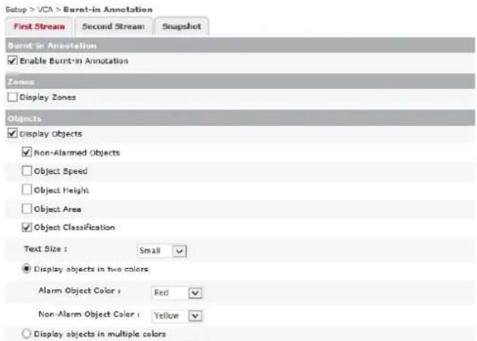
Figure 7-74: Setup Tab –VCA Menu –Burnt-In Annotaon Sengs 1(screenshot cont'd on next page)

Figure 7-75: Setup Tab –VCA Menu –Burnt-In Annotaon Sengs 2
2). From the Burnt-In Annotation settings, a user may configure settings related to the on-screen display of VCA components in live and recorded footage. Settings may be configured for each individual stream profile by selecting the desired profile tab near the top of the settings form.
NOTE:
VCA components are visible in the VCA Rules and Zones settings page video preview as well as on the Live tab (if chosen to be displayed in the Live tab right-click menu). These are for reference during configuration only and are not burnt-in to recorded video. Enable burnt-in annotation for desired VCA components to ensure they are visible on recorded video.
3). Click Enable Burnt-In Annotation to enable burnt-in annotations and reveal related options and settings.
| Zones | Display Zones – Select this option to burn any VCA zones into the camera image. |
| Display Objects – Select this option to burn in VCA object trackers. The following options may be enabled for burnt-in object tracking: | |
| Objects | Non Alarmed Objects – Burn-in object tracking for objects not triggering an alarm/event.Object Speed – Burn-in the object’s speed value (km/h).Object Height – Burn in the objects height measurement value.Object Area – Burn in the object area measurement value ( m^-2 ).Object Classification – Burn in the objects classificationsText Size – Select a preconfigured size (small, medium, large) for the burnt-in text.Display Objects in Two Colors – Display burnt-in colors for Alarmed and Non-Alarmed (Objects not currently triggering an alarm/event) objects differently. Select the color for each object type from the available drop-down menu.Displays Objects in Multiple Colors – Enable multiple burnt-in object tracking colors when multiple objects are present. |
| Counters | Display Counters – Select this option to burn in any VCA counters into the camera image. A user may choose to burn-in the counter’s Value, Name or both by checking off the corresponding box.Display System Messages – Select this option to burn system messages into the camera image. |
| System Messages | Display Current Profile – Select this option to burn the current stream profile’s information into the camera image.Text Size – Select a preconfigured size (small, medium, large) for the burnt-in text. |
| Diagnostics | Display Counting Line Events – Select this option to burn counting line event information into the camera image. |
4). Click Apply to save settings changes. Click Restore Defaults to restore settings to their default state.
COUNTER REPORTING SETTINGS
Steps:
1). Opening the Setup Tab>VCA drop-down menu and clicking the Counter Reporng link will open the Counter Reporng sengs page.
2). The Counter Reportng sengs page is split across three tabs: The Reportng Service, Database Service and E-mail Nocaons tabs.
Each is outlined in the below seconds.
REPORTING SERVICE TAB – COUNTER REPORTING SETTINGS
Steps:
1). From the Reporng Service tab, a user may congregate sengs related to the reporng of VCA counter data.

Figure 7-76: Setup Tab –VCA Menu –Counter Reporng Setngs – Reporng Service Tab
2). If desired, select a Predened Request from the drop-down menu to autoll the Request Command informaon. Available opons include One Hour, Today, Yesterday, One Day (the last 24 hours), This Week (rst day of the current week unl present), Last Week, One Week, This Month (rst day of the current month unl present) and Last Month.
3). If a custom counter report is desired, ll out the required elds in the Request Command secon manually.
Available sengs include:
| Request Command | Descripon |
| Time | Fill out the To and From elds to designate a me range for the counter report. |
| Counter ID | Select the counter to report data on. An individual counter may be chosen by selecng its corresponding ID (1-19). Select Acve to report on only acve counters. Select All to report on all counters. |
| Table (Sampling) | Select the table to use in the report. Each table features a separate Sampling Interval and Roll-Over Count. See Database Service Tab for more informaon on conguring counter report tables. |
| Sorng Order | Select whether the results should be displayed in Ascending or Descending order. |
| Value Type | Select whether the displayed results should be Absolute value of each counter, or the Dierence between counters. |
4). Under the Request secon, select the report style. Available styles include: Table, Bar and CSV. Please note, a Counter Report cannot be generated without enabling Database Service on the Database Service tab. Please enable Database Service to enable counter report generaon.
5). Aer selecng a style, a pop-up will open with your report and a URL link to the report will also be available in the Request URL eld.
DATABASE SERVICE TAB – COUNTER REPORTING SETTINGS
Steps:
1). From the Database Service tab, a user may enable Database Service (required for counter reporting and counter report email nocaons) and congure related sengs.
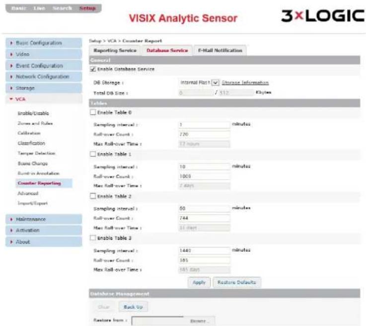
Figure 7-77: Setup Tab –VCA Menu –Counter Reporng Seings– Database Service Tab
2). Enabling Database Service will create a database to store counter reporting data.
3). Select the DB Storage medium by choosing either Flash (internal) or SD (removable storage) from the drop-down menu. Aer selecng your storage medium, designate a Total DB Size (in kilobytes). The maximum available amount of storage will vary depending on your chosen storage medium.
4). Under the Tables secon, a user may enable up to four DB tables by checking o the corresponding Enable Table x box.
The following table sengs can be congured:
| Table Sengs | Descripon |
| Sampling Interval | Set the table’s sampling interval (in minutes). |
| Roll-Over Count | Set the table’s Roll-Over count. New entries will begin to replace the oldest exisng entries when the count has reached this value. |
| Max Roll-Over Time | The maximum amount of me that can be allowed to transpire before overwring of the oldest exisng entries will begin based on the dened Sampling Interval and Roll-Over Count values. This seng is not directly congurable. |
5). Click Apply to save sengs changes. Click Restore Defaults to restore all sengs to their default state.
6). Under the Database Management secon, a user may select Clear to clear the current database. Select Back-Up to make a back-up copy of the database and its current structure and content. The backup will be automatically downloaded to your browser's Downloads folder.
7). If the database requires restoraon, select the Browse buon next to the Restore From eld and select a DB backup le to restore DB structure and contents.
E-MAIL NOTIFICATION TAB – COUNTER REPORTING SETTINGS
Steps:
1). From the E-Mail Noficaon tab, a user may congure VCA counter report e-mail nocaons and their related sengs.

Figure 7-78: Setup Tab -VCA Menu - Counter Reporng Setngs-E-Mail Noficaons Tab
2). To enable VCA counter reporting e-mail nocaons, check-o Enable E-Mail Nocaon.
3). Once nocaons are enabled, a user may Add, Modify or Remove a counter reporting e-mail nocaon recipient. When adding/modifying a recipient, recipient and report sengs may also be edited.
4). Select a recipient from the list to display recipient informaon. To remove a recipient, select the desired recipient from the list and click Remove.
5). SMTP (E-mail Server) Sengs must be congured in order for e-mail nocaons to funcon. Click the Go to SMTP (E-Mail) Sengs link to open the SMTP sengs form and congure sengs as necessary. See SMTP (E-Mail Server) Sengs for more info.
ADD/MODIFY A COUNTER REPORT E-MAIL NOTIFICATION RECIPIENT
Steps:
1). To add a recipient, click the Add... buon (if modifying, select the desired recipient from the list and click Modify...). The Add/Modify E-Mail Recipient form will deploy.
1). In the E-Mail Conguraon secon of the form, a user may enter basic recipient info.

Figure 7-79: Setup Tab –VCA Menu - Counter Reporng Setngs–E-Mail Noficaons Tab – Add/Modify E-Mail Recipient
2). Fill in the Name, Descripon and E-mail Address elds for the desired recipient.
| E-Mail Recipient Seng | Descripon |
| Name | Name the recipient. This name will be used to identify this parcular recipient when assigning it to an e-mail nocaaon. |
| Descripon | Provide a brief descripon of the recipient (intended use, etc...). This descripon will be displayed when the schedule is selected on the schedule sengs page. |
| E-Mail Address | Enter the e-mail address of the recipient. |
SCHEDULE CONFIGURATION
Steps:
1). In the Schedule Conguraon secon of the Add/Modify Recipient window, a user may congure a nocaon schedule for the recipient.
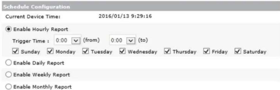
Figure 7-80: Setup Tab –VCA Menu - Counter Reporng Setngs–E-Mail Noficaons Tab – Schedule Conguraon
2). Enable an Hourly, Daily, Weekly or Monthly report. When the desired report is selected, related sengs will be deployed and can be customized.
| Schedule Sengs | Descripon |
| Hourly | Enable hourly reporting to send a report on a customized hourly basis.SelectFromandTotrigger mes from the available drop-down menus to choose which hours in a day the hourly report will be sent. If 1:00 and 8:00 are selected asFromandTorespectively, then a report will be e-mailed on the hour from 01:00 to 08:00.Select the days of week the report will be emailed on. The report will be sent on the chosen days, during the designated trigger hour range. |
| Daily | Enable daily reporting to send reports on a customized daily basis.Select aTrigger Timefrom the drop-down menu. The report will be e-mailed at the selected me.Select days of week the report will be emailed on. The report will be sent on the chosen days, at the designated trigger hour. |
| Weekly | Enable weekly reporting to send reports on a customized weekly basis.Select aTrigger DayandTrigger Timefrom the available drop-down menus. The report will be emailed to the recipient on the chosen day, at the chosen me. |
| Monthly | Enable monthly reporting to send reports on a customized monthly basis.Select aTrigger Day(1-31) andTrigger Timefrom the available drop-down menus. Reports will be emailed to the recipient on the chosen day of the month, at the chosen me. |
1). In the Report Conguraon secon of the Add/Modify Recipient window, a user may congure an email counter report sengs.

Figure 7-81: Setup Tab –VCA Menu - Counter Reportng Setngs–E-Mail Noficaons Tab – Report Conguraon
| Report Seng | Descripon |
| Time | Select Report All Data to report all counter data within the schedule range. If a custom range is desired, ll out the To and From elds to designate a me range for the counter report. |
| Counter ID | Select the counter to report data on. An individual counter may be chosen by selecng its corresponding ID (1-19). Select Acve to report on only acve counters. Select All to report on all counters. |
| Table (Sampling) | Select the table(s) to use in the report. Each table features a separate Sampling Interval and Roll-Over Count. See Database Service Tab for more informaon on conguring counter report tables. |
| Sorng Order | Select whether the results should be displayed in Ascending or Descending order. |
| Value Type | Select whether the displayed results should be Absolute value of each counter, or the Dierence between counters. |
| Format | Select the report format for the email counter report. |
2). Click Send Test Report to send a test report using the currently congured sengs to the e-mail entered in the E-mail Conguraon secon.
3). Click OK to save the new recipient. Click Cancel to close the window without saving the recipient.
ADVANCED VCA SETTINGS
Steps:
1). Opening the Setup Tab>VCA drop-down menu and clicking the Advanced link will open the Advanced VCA sengs page.

Figure 7-82: Setup Tab –VCA Menu –Advanced VCA Sengs
2). From the Advanced VCA sengs page, a user may congure sengs related to advanced operaon of VCA video analytics.
Congurable sengs include:
| Advanced Seng | Descripon |
| Alarm Hold-O Time | Congure the amount of me (in seconds) allowed to transpire between a VCA event/alarm creaon and the acon which triggered the event/alarm. |
| Measurement Units | Select a desired measurement system from the available drop-down. These units will be used for approximang VCA object height/area/speed. Metric is the camera default. |
| Metadata Format | Metadata - Select your desired metadata categories: Event, Object, and Counng. Select Do Not Send Empty Metadata Packets to avoid sending packets when there is no data available.Diagnosc Metadata - Select your desired diagnosc metadata categories: Blob (Moon), Counng Line, Tamper and Scene Change. |
| Staonary Object Hold-On Time | Congure the amount of me the camera will track a staonary VCA object before it ceases tracking. |
| Advanced Sengs | Descripon |
| Tracking Opons | Congure the Minimum Tracked Object Size. Select Auto to only track objects equal to or larger than the smallest object classicaon.To congure a custom size, select the Blobmap Pixels opon and enter the desired value. |
| Display Opons | Congure a Minimum Alarm Object Display Time. Objects which have triggered an event/alarm will display an alarm tracker (red object tracker) for, at a minimum, the designated amount of me. |
| Detecon Point of Tracked Items | Congure a detecon point for tracked objects:1). Default - Default mode will use Centroid if calibrated as overhead or Midboom if calibrated as sideview or if the camera is uncalibrated.2). Centroid – Detecon point for objects is at centroid.Recommended for overhead camera3). Midboom – Detecon point for objects is the Midboom region. Recommended for sideview or uncalibrated cameras. |
| Global Restore Defaults | Select Restore All Default VCA Sengs to restore all VCA sengs to their factory default state. |
3). Click Apply to save sengs. Click Restore Defaults to restore all VCA advanced sengs to their default state.
IMPORT/EXPORT SETTINGS
Steps:
1). Opening the Setup Tab>VCA drop-down menu and clicking the Import/Export link will open the Import/Export VCA Sengs page.

Figure 7-83: Setup Tab –VCA Menu –Import/Export Sengs
2). From the Import/Export VCA Sengs page, a user may export or import an .xml containing VCA conguraon sengs.
3). Click the Export buon to download an xml le (vca_cong.xml) to your browsers downloads desnaon. This le can be imported to other cameras to assign them the same VCA conguraons as the device from which is was exported.
4). Under the VCA Configuraon Import secon, a user may select which VCA sengs conguraon to import from the le.
5). To import a VCA sengs le, click the Browse buon, navigate to and select the desired xml le and click Open. Only VCA sengs conguraons which have been checked-o in the VCA Conguraon Import secon will be imported to the device.
7.7 Maintenance Menu
USERS
Steps:
1). Opening the Setup Tab>Maintenance drop-down menu and clicking the Users link will open the Users sengs page.
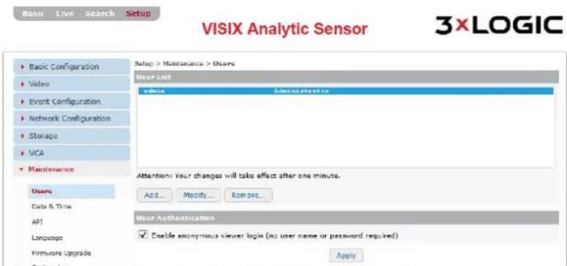
Figure 7-84: Setup Tab - Maintenance Menu - Users
2). From the Users page, a user may view the camera's list of user proles. A user may also add, modify or remove a user prole. Details regarding each acon are outlined in the proceeding sub-seconds of this manual. User sengs can also be edited from both the Basic Tab>Camera Conguraon>Users and the Setup (Advanced) Tab>Basic Conguraon>Users sengs pages.
ADD A USER
Steps:
1). Click the Add... to add a new user prole. The Add User form (pictured right) will deploy.
| Form Field | Descripon |
| Username and Password | Enter a username and password for the new user. |
| Conrm Password | Conrm the previously entered password. |
| User Group | Choose a User Group for the user. |

Figure 7-85: Setup Tab – Maintenance Menu – Users – Add User
2). Aer nishing conguraon, click Apply to save the new sengs.
MODIFY A USER
Steps:
1). Click the Modify...buon to modify an exisng user prole. The Modify User form (pictured right) will deploy.
| Form Field | Descripon |
| Username and Password | Enter a username and password for the new user. |
| Conrm Password | Conrm the previously entered password. |
| User Group | Choose a User Group for the user. |

Figure 7-86: Setup Tab – Maintenance Menu – Users – Modify User
2). Aer nishing conguraon, click Apply to save the new sengs.
REMOVE A USER
Steps:
1). Click the Remove buon to remove an exisng user prole. This acon is only available when a user prole is selected in the list. You will be prompted for a conrmaon before nalizing the removal.
USER AUTHENTICATION
Steps:
1). Check-o Enable Anonymous Viewer Login to enable anonymous viewing (no username or password required) of the camera's live view
DATE & TIME SETTINGS
Steps:
1). Opening the Setup Tab>Maintenance drop-down menu and clicking the Date & Time link will open the Date & Time sengs page.

Figure 7-87 Setup Tab – Maintenance Menu – Date and Time Settings
2). From the Date & Time sengs page, a user may edit a camera's me sengs including me zone, me server, date and me format and me synchronizaon source.
| Time Seng | Descripon |
| Current Camera Encoder Time | Displays the current camera me |
| Conguraon | Time Zone - Select the camera me zone.Sync Source - Set the acve NTP server as your me sync source. Click the Go to NTP Conguraon to be taken to the NTP Sengs page.Date and Time Format – Choose a predened date-format. Enable 24-Hour to use standard 24 hour me. |
| New Camera / Encoder Time | Set this Computer’s Date and Time – Selecng this opon will sync the camera’s me with your current computer system.Set with NTP Server - Selecng this opon will sync the camera’s me with the displayed NTP server (Default: me.windows.com)Set Manually – Select this opon to manually congure the camera’s date and me. |
3). Click Apply to save the new me sengs.
API SETTINGS
Steps:
1). Opening the Setup Tab>Maintenance drop-down menu and clicking the API link will open the API sengs page.
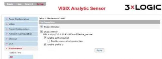
Figure 7-88 Setup Tab -Maintenance Menu -API Setngs
2). From the API sengs page, a user may acvate sengs related to the camera's applicaon programming interface.
Congurable sengs include:
| Storage Detail | Descripon |
| Enable Genetec | Enable integraon with Genetec security center. |
| Enable ONVIF | Enable ONVIF on the camera:Enable Authencaon - Enable ONVIF Authencaon. The user may also enable Replay Aack Protecon to protect the camera against malicious/ fraudulent acvity.Enable Prole G – Enable ONVIF Prole G. |
3). Click Apply to save sengs changes.
LANGUAGE SETTINGS
Steps:
1). Opening the Setup Tab>Maintenance drop-down menu and clicking the Language link will open the Language sengs page.

Figure 7-89 Setup Tab -Maintenance Menu -Language Sengs
2). From the Language sengs page, a user may select the camera interface language. Select a desired language from the available drop-down menu. Languages include: English, Chinese and Korean.
3). Click Apply to save sengs changes.
FIRMWARE UPGRADE
Steps:
1). Opening the Setup Tab>Maintenance drop-down menu and clicking the Firmware Upgrade link will open the Firmware Upgrade page.

Figure 7-90 Setup Tab -Maintenance Menu -Firmware Upgrade Setngs
2). From the Firmware Upgrade page, a user may update the device's hardware rmware. To update device rmware, simply click the Browse buon, navigate to the locaon of the rmware le on your current system and select the le for use. A Start buon will appear when a valid .enc le has been selected.
3). Click Start to begin the rmware update process.
SYSTEM LOG SETTINGS
Steps:
1). Opening the Setup Tab>Maintenance drop-down menu and clicking the System Log link will open the System Log Sengs page.

Figure 7-91 Setup Tab -Maintenance Menu -System Log Sengs
2). From the System Log page, a user can click Download System Log for an updated copy of the log. If desired, check-o Enable Auto Backup and conjure the following details for auto backup of the system log to an FTP service of your choosing.
FTP conncon sengs are described below:
| FTP Seng | Descripon |
| Name | Name the FTP server. This name will be used to identify this parcular FTP when selecng it for storage purposes. |
| IP Address/Port | Enter network conncon values for the desired FTP Server. |
| Target Directory | Enter the target desnaon directory on the FTP for storing uploaded les. |
| Account/Password | Enter the user login credenals for the FTP. 3xLOGIC recommends using an administrave level account when possible to avoid permissions conicts. |
| Filename Format | Assign the lename format for the .log les uploaded to the FTP. |
3). If you have previously congured an FTP service via the FTP Nocaon sengs, click Show Nocaon List. A list of congured FTP nocaons will appear. To instantly load an FTP nocaon's FTP connection info into the System Log-FTP conguraon form, select the desired nocaon from the list and click Load Nocaon into Sengs.
4). Click Apply to save sengs changes.
CONFIGURATION IMPORT/EXPORT SETTINGS
Steps:
1). Opening the Setup Tab>Maintenance drop-down menu and clicking the Conguraon Import/Export link will open the Conguraon Import/Export page.

Figure 7-92 Setup Tab - Maintenance Menu - Configure Import/Export Page
2). From the Conguraon Import/Export page, a user can export the cameras current sengs conguraon (.dat format) or import a sengs conguraon le to apply to the camera.
3). To export the camera's current sengs, click the Export buon. The camera sengs le will be downloaded to your browser's download desnaon.
4). To import sengs, click the Browse... and navigate to the les locaon on your system. When a le is selected, an Import buon will appear. Click Import to import sengs from the selected le.
CAUTION:
Imporng a sengs le will overwrite all exisng camera sengs.
RESET ALL SETTINGS
Steps:
1). Opening the Setup Tab>Maintenance drop-down menu and clicking the Reset All Sengs link will open the Reset All Sengs page.

Figure 7-93 Setup Tab -Maintenance Menu -Reset All Setngs
2). From the Reset All Sengs page, a user may reset all camera sengs to their factory default state.
3). Before reseng, a user may choose to preserve Network and Time Zone sengs. Check-o Preserve Network Sengs and/or Preserve Time Zone Sengs.
4). Aer designang sengs to be preserved, click Reset All Sengs to restore sengs to their factory defaults.
REBOOT
Steps:
1). Opening the Setup Tab>Maintenance drop-down menu and clicking the Reboot link will open the Reset All Sengs page. To reboot the system, click and follow the on-screen instrucons.
3XLOGIC
Steps:
1). Opening the Setup Tab>Maintenance drop-down menu and clicking the 3xLOGIC link will open the 3xLOGIC VIGIL Camera Server Soware sengs page.

Figure 7-94 Setup Tab -Maintenance Menu -3xLOGIC Soware Sengs
2). From the 3xLOGIC VIGIL Camera Server soware sengs page, a user can view the camera's current VIGIL Camera Server soware version. The user can also Stop (shut down) or Restart the camera's VIGIL soware by clicking the corresponding buons.
3). A user may also update the camera's VIGIL Server Camera soware from this page. To begin, click the Browse buon in the Update secon. This will deploy a standard le browser. Navigate to the update le on your system and select it. An Update buon will appear when valid le has been chosen. Click Update to begin the soware update process.
4). To uninstall the current VIGIL Server Camera soware, click the Uninstall buon.
7.8 Acvaon Menu
ACTIVATE
Steps:
1). Opening the Setup Tab>Acvaon drop-down menu and clicking the Acvate link will open the Acvaon sengs page.
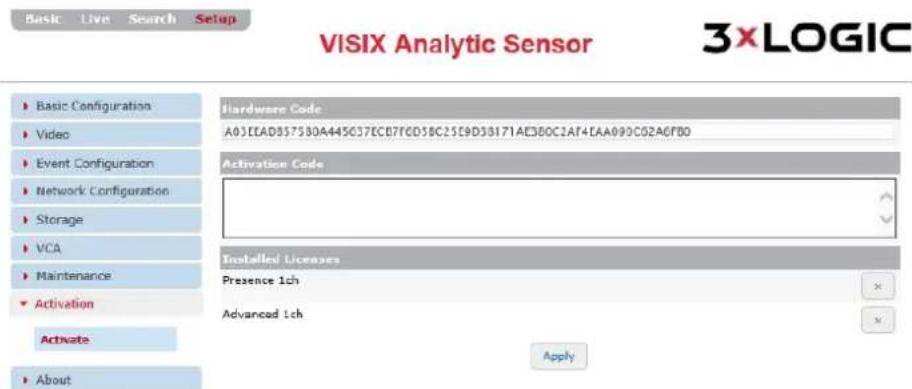
Figure 7-95 Setup Tab -Acvation Menu -Activaon Form
2). From the Acvaon sengs page, a user may view the camera's Hardware Code and any installed licenses. To register new license, enter the acvaon code into the Acvaon Code text eld. Valid codes will be automatically processed and the corresponding license will appear in the Installed Licenses list.
3). Click Apply to save sengs changes.
7.9 About Menu
INFORMATION
Steps:
1). Opening the Setup Tab> About drop-down menu and clicking the Informaon link will open the camera informaon page.
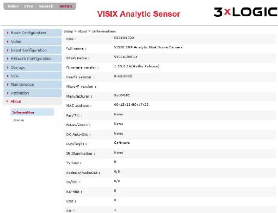
Figure 7-96 Setup Tab -About Menu -Informaon Form
The Informaon page provides a user with at-a-glance informaon regarding the following camera components/specicaons:
Serial Number
■ Full and Short Names
■ Firmware Version
■ VIGIL Server Camera (Userfs) Soware Version
■ Micro-P Version
■ Manufacturer Name
MAC Address
■ Pan/Tilt Capability
■ Focus/zoom Capability
■ DC-Auto Iris Info
■ Day/Night Mode Info
■ IR Illuminaon Specs
TV-Out
■ Audio In/Audio Out
DI/DO
RS-485
USB
SD
LICENSE
Steps:
1). Opening the Setup Tab>About drop-down menu and clicking the About link will open the License informaon page.

VISIX Analytic Sensor


Figure 7-94 Setup Tab -About Menu -License Informaon
2). The License Informaon page provides a user with at-a-glance informaon regarding the licensing for several of the camera and soware components.
8 IP Address – Hexadecimal/Decimal Conversion Table
Refer to the following table when converng the MAC address of the device to the IP address:
| Hex | Dec | Hex | Dec | Hex | Dec | Hex | Dec | Hex | Dec | Hex | Dec | Hex | Dec |
| 0 | 0 | 25 | 37 | 4A | 74 | 6F | 111 | 94 | 148 | B9 | 185 | DE | 222 |
| 1 | 1 | 26 | 38 | 4B | 75 | 70 | 112 | 95 | 149 | BA | 186 | DF | 223 |
| 2 | 2 | 27 | 39 | 4C | 76 | 71 | 113 | 96 | 150 | BB | 187 | E0 | 224 |
| 3 | 3 | 28 | 40 | 4D | 77 | 72 | 114 | 97 | 151 | BC | 188 | E1 | 225 |
| 4 | 4 | 29 | 41 | 4E | 78 | 73 | 115 | 98 | 152 | BD | 189 | E2 | 226 |
| 5 | 5 | 2A | 42 | 4F | 79 | 74 | 116 | 99 | 153 | BE | 190 | E3 | 227 |
| 6 | 6 | 2B | 43 | 50 | 80 | 75 | 117 | 9A | 154 | BF | 191 | E4 | 228 |
| 7 | 7 | 2C | 44 | 51 | 81 | 76 | 118 | 9B | 155 | C0 | 192 | E5 | 229 |
| 8 | 8 | 2D | 45 | 52 | 82 | 77 | 119 | 9C | 156 | C1 | 193 | E6 | 230 |
| 9 | 9 | 2E | 46 | 53 | 83 | 78 | 120 | 9D | 157 | C2 | 194 | E7 | 231 |
| 0A | 10 | 2F | 47 | 54 | 84 | 79 | 121 | 9E | 158 | C3 | 195 | E8 | 232 |
| 0B | 11 | 30 | 48 | 55 | 85 | 7A | 122 | 9F | 159 | C4 | 196 | E9 | 233 |
| 0C | 12 | 31 | 49 | 56 | 86 | 7B | 123 | A0 | 160 | C5 | 197 | EA | 234 |
| 0D | 13 | 32 | 50 | 57 | 87 | 7C | 124 | A1 | 161 | C6 | 198 | EB | 235 |
| 0E | 14 | 33 | 51 | 58 | 88 | 7D | 125 | A2 | 162 | C7 | 199 | EC | 236 |
| 0F | 15 | 34 | 52 | 59 | 89 | 7E | 126 | A3 | 163 | C8 | 200 | ED | 237 |
| 10 | 16 | 35 | 53 | 5A | 90 | 7F | 127 | A4 | 164 | C9 | 201 | EE | 238 |
| 11 | 17 | 36 | 54 | 5B | 91 | 80 | 128 | A5 | 165 | CA | 202 | EF | 239 |
| 12 | 18 | 37 | 55 | 5C | 92 | 81 | 129 | A6 | 166 | CB | 203 | F0 | 240 |
| 13 | 19 | 38 | 56 | 5D | 93 | 82 | 130 | A7 | 167 | CC | 204 | F1 | 241 |
| 14 | 20 | 39 | 57 | 5E | 94 | 83 | 131 | A8 | 168 | CD | 205 | F2 | 242 |
| 15 | 21 | 3A | 58 | 5F | 95 | 84 | 132 | A9 | 169 | CE | 206 | F3 | 243 |
| 16 | 22 | 3B | 59 | 60 | 96 | 85 | 133 | AA | 170 | CF | 207 | F4 | 244 |
| 17 | 23 | 3C | 60 | 61 | 97 | 86 | 134 | AB | 171 | D0 | 208 | F5 | 245 |
| 18 | 24 | 3D | 61 | 62 | 98 | 87 | 135 | AC | 172 | D1 | 209 | F6 | 246 |
| 19 | 25 | 3E | 62 | 63 | 99 | 88 | 136 | AD | 173 | D2 | 210 | F7 | 247 |
| 1A | 26 | 3F | 63 | 64 | 100 | 89 | 137 | AE | 174 | D3 | 211 | F8 | 248 |
| 1B | 27 | 40 | 64 | 65 | 101 | 8A | 138 | AF | 175 | D4 | 212 | F9 | 249 |
| 1C | 28 | 41 | 65 | 66 | 102 | 8B | 139 | B0 | 176 | D5 | 213 | FA | 250 |
| 1D | 29 | 42 | 66 | 67 | 103 | 8C | 140 | B1 | 177 | D6 | 214 | FB | 251 |
| 1E | 30 | 43 | 67 | 68 | 104 | 8D | 141 | B2 | 178 | D7 | 215 | FC | 252 |
| 1F | 31 | 44 | 68 | 69 | 105 | 8E | 142 | B3 | 179 | D8 | 216 | FD | 253 |
| 20 | 32 | 45 | 69 | 6A | 106 | 8F | 143 | B4 | 180 | D9 | 217 | FE | 254 |
| 21 | 33 | 46 | 70 | 6B | 107 | 90 | 144 | B5 | 181 | DA | 218 | FF | 255 |
| 22 | 34 | 47 | 71 | 6C | 108 | 91 | 145 | B6 | 182 | DB | 219 | ||
| 23 | 35 | 48 | 72 | 6D | 109 | 92 | 146 | B7 | 183 | DC | 220 | ||
| 24 | 36 | 49 | 73 | 6E | 110 | 93 | 147 | B8 | 184 | DD | 221 |
9 Revision History
| MAN# | DATE(M/D/Y) | Comments |
| 11-2015-1 | 11/02/2015 | Styled |
| 01-2016-22 | 01/22/2016 | Finalized initial dra. |
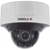
- VISIX V-Series All-in-One Cameras
- Regulatory Informaon
- FCC Informaon
- FCC Conditions
- EU Conformity Statement
- Safety Instrucon
- WARNING:
- CAUTION:
- NOTE:
- Table of Contents
- VISIX V-SERIES ALL-IN-ONE CAMERAS .... 10
- IDENTIFYING THE CAMERA ON YOUR NETWORK....11
- ACCESSING THE CAMERA BROWSER INTERFACE....14
- QUICK START....15
- BASIC TAB....38
- VISIX V-Series All-in One Cameras
- Introducon
- Identifying the Camera on your Network
- Idenfying Camera IP Address
- MANUALLY IDENTIFY CAMERA IP ADDRESS (MAC ADDRESS HEX CONVERSION)
- Steps:
- AUTOMATICALLY IDENTIFY CAMERA IP ADDRESS WITH 3XLOGIC CAMERA SETUP UTILITY
- VIDEO PREVIEW USING THE 3XLOGIC CAMERA SETUP UTILITY
- Accessing the Camera Browser Interface
- Logging In to the Camera
- ACTIVEX INSTALLATION
- Quick Start
- View Live and Playback (Recorded) Video
- VIEWING LIVE VIDEO
- VISIX Analytic Sensor
- Congure VIGIL Connect Alias
- Congure a Video Analycs (VCA) Rule (Analycs License Required)
- ENABLING VCA
- VCA ANALYTICS CALIBRATION
- VCA ANALYTICS RULE CONFIGURATION
- CONFIGURING A LINE (TRIPWIRE) WITH ON-SCREEN COUNTER
- CONFIGURING A DWELL TIMER ZONE
- PREVIEWING ANALYTICS OVERLAY
- Integrang All-in-One Camera with VIGIL Server Using VIGIL Analycs Bridge
- INSTALLATION OF ANALYTICS BRIDGE
- VIGIL SERVER CONFIGURATION
- VIGIL SERVER CONFIGURATION – NETWORK CAMERA SETTINGS
- VIGIL ANALYTICS BRIDGE – LAUNCHING THE VIGIL ANALYTICS BRIDGE
- CONFIGURING A 3XLOGIC ALL-IN-ONE CAMERA IN THE VIGIL ANALYTICS BRIDGE
- Adding All-in-One Camera to VIGIL Suite Ulies
- VIGIL CLIENT - ADDING A V-SERIES ALL-IN-ONE CAMERA
- VIGIL VCM - ADDING A V-SERIES ALL-IN-ONE CAMERA
- 3XLOGIC VIEW LITE II MOBILE (ANDROID AND IOS) – ADDING A V-SERIES ALL-IN-ONE CAMERA
- 3XCLOUD CROSS-PLATFORM WEB CLIENT – ADDING A V-SERIES ALL-IN-ONE CAMERA
- Reboot and Reset to Factory Default Procedures
- REBOOTING THE CAMERA USING THE RESET BUTTON
- REBOOT THE CAMERA USING THE 3XLOGIC CAMERA SETUP UTILITY
- REBOOT THE CAMERA VIA WEB BROWSER INTERFACE
- RESETTING CAMERA SETTINGS TO FACTORY DEFAULT
- RESET TO FACTORY DEFAULT SETTINGS VIA CAMERA WEB INTERFACE
- Basic Tab
- Camera Status Menu
- STATUS
- Camera Conguraon Menu
- SITE INFORMATION
- TIME
- USERS
- ADD A USER
- MODIFY A USER
- REMOVE A USER
- VIDEO
- NETWORK
- MAINTENANCE
- Storage Conguraon Menu
- SD CARD
- SD STORAGE LIST
- RECORDING DEVICE CONTROL
- Live and Search (Playback) Tabs
- Live Tab
- LIVE VIEWER – OPTIONS PANEL – OPTIONS TAB
- LIVE VIEWER – OPTIONS PANEL – STATUS TAB
- Search (Playback) Tab
- Setup (Advanced) Tab
- Basic Conguraon Menu
- USER AUTHENTICATION
- TCP/IP
- BASIC CONFIGURATION MENU - TCP/IP SETTINGS - IPV6 SETTINGS CONFIGURATION
- DATE & TIME
- STREAM
- STREAM SETTINGS
- SNAPSHOT SETTINGS
- FOCUS ASSIST
- Video Menu
- CAMERA
- GENERAL SETTINGS
- VIDEO APPEARANCE SETTINGS
- VIDEO TRANSFORM SETTINGS
- EXPOSURE SETTINGS
- DIGITAL WIDE DYNAMIC RANGE SETTINGS
- WHITE BALANCE SETTINGS
- IMAGE SIGNAL PROCESSING SETTINGS
- VIDEO STABILIZATION SETTINGS
- BURNT-IN TEXT (OSD)
- ENCODER PROFILE
- ADDING OR MODIFYING AN ENCODER PROFILE
- PRIVACY MASK
- VIDEO OUT (BNC)
- Event Conguraon Menu
- EVENT RULES
- ADDING OR MODIFYING AN EVENT RULE
- EVENT SOURCE (TRIGGERS) TAB - ADDING/MODIFYING EVENT RULE
- EVENT ACTION TAB – ADDING/MODIFYING EVENT RULE
- MOTION DETECTION
- 3XLOGIC
- FACE DETECTION
- NETWORK LOSS
- HEART BEAT
- SCHEDULE
- ADDING/MODIFYING A SCHEDULE
- E-MAIL RECIPIENTS
- ADD/MODIFY AN E-MAIL RECIPIENT
- FTP NOTIFICATION
- ADD/MODIFY AN FTP SERVER
- HTTP NOTIFICATIONS
- ADD/MODIFY AN HTTP SERVER
- TCP NOTIFICATIONS
- TCP SERVER
- MULTICAST NOTIFICATION
- Network Conguraon Menu
- TCP/IP SETTING
- NETWORK CONFIGURATION MENU - TCP/IP SETTINGS - IPV6 SETTINGS CONFIGURATION
- WEB SERVER SETTINGS
- NTP SETTINGS
- UPNP SETTINGS
- RTSP/RTP SETTINGS
- RTSP CONFIGURATION
- SRTP
- UNICAST
- MULTICAST
- RTMP SETTINGS
- MDNS SETTINGS
- WS-DISCOVERY SETTINGS
- SMTP (E-MAIL SERVER) SETTINGS
- DDNS SETTINGS
- SNMP SETTINGS
- IP FILTERING SETTINGS
- HOSTED SERVICE SETTINGS
- Storage Menu
- SD SETTINGS
- FTP SETTINGS
- RECORDING
- CONTINUOUS (RECORDING) SETTINGS
- VCA Menu
- ENABLE/DISABLE
- ZONES AND RULES SETTINGS
- ZONES AND RULES SETTINGS – ZONES & RULES TAB
- CREATE ZONE
- Name
- Color
- Detect/Non-Detect
- CREATE LINE (TRIPWIRE)
- CREATE COUNTER
- ZONES AND RULES SETTINGS – LOGICAL RULES TAB
- ADDING/MODIFYING A LOGICAL RULE
- CALIBRATION SETTINGS
- CLASSIFICATION SETTINGS
- TAMPER DETECTION SETTINGS
- SCENE CHANGE SETTINGS
- BURNT-IN ANNOTATION SETTINGS
- COUNTER REPORTING SETTINGS
- REPORTING SERVICE TAB – COUNTER REPORTING SETTINGS
- DATABASE SERVICE TAB – COUNTER REPORTING SETTINGS
- E-MAIL NOTIFICATION TAB – COUNTER REPORTING SETTINGS
- ADD/MODIFY A COUNTER REPORT E-MAIL NOTIFICATION RECIPIENT
- SCHEDULE CONFIGURATION
- ADVANCED VCA SETTINGS
- IMPORT/EXPORT SETTINGS
- Maintenance Menu
- DATE & TIME SETTINGS
- API SETTINGS
- LANGUAGE SETTINGS
- FIRMWARE UPGRADE
- SYSTEM LOG SETTINGS
- CONFIGURATION IMPORT/EXPORT SETTINGS
- RESET ALL SETTINGS
- REBOOT
- Acvaon Menu
- ACTIVATE
- About Menu
- INFORMATION
- LICENSE
- IP Address – Hexadecimal/Decimal Conversion Table
Brand : 3xLOGIC
Model : VISIX V
Category : Surveillance Camera