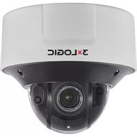
VX-2M-OD3-RIAH - Security Camera 3xLOGIC - Free user manual and instructions
Find the device manual for free VX-2M-OD3-RIAH 3xLOGIC in PDF.


| Product Type | Outdoor IP Dome Camera |
| Brand | 3xLOGIC |
| Model | VX-2M-OD3-RIAH |
| Series | VISIX S-Series |
| Resolution | 2 Megapixel (1920x1080) |
| Lens Type | Fixed |
| Night Vision | IR LEDs (effective range not specified) |
| Power Supply | Power over Ethernet (PoE) 802.3af |
| Weatherproof Rating | IP66 (typical for outdoor dome) |
| Operating Temperature | -40°C to 50°C (estimated) |
| Video Compression | H.264/H.265 (likely) |
| MicroSD Card Slot | Yes (for local storage) |
| Default IP Address | 192.0.0.64 |
| Default Port | 8000 |
| Supported Mounts (Accessories) | Wall Mount (VX-WM-147), Pendant Mount (VX-PM-147), Pole Mount (VX-POLE-147), Corner Mount (VX-CM-147) |
| Package Contents | Camera with Junction Housing, Mounting Base, Screws & Anchors, T20 Torx Key, Video Test Monitor Connector, Cable Routing Hole Cap, RJ-45 Gasket Piercing Cap |
| Reset Method | Press and hold RESET button for 10 seconds during power-on |
| Web Interface | Yes, requires Web Components plug-in |
| Compatible Software | VIGIL Server, VIGIL Client, View Lite II |
Frequently Asked Questions - VX-2M-OD3-RIAH 3xLOGIC
User questions about VX-2M-OD3-RIAH 3xLOGIC
0 question about this device. Answer the ones you know or ask your own.
Ask a new question about this device
Download the instructions for your Security Camera in PDF format for free! Find your manual VX-2M-OD3-RIAH - 3xLOGIC and take your electronic device back in hand. On this page are published all the documents necessary for the use of your device. VX-2M-OD3-RIAH by 3xLOGIC.
USER MANUAL VX-2M-OD3-RIAH 3xLOGIC
natural_image
Front view of a 3x LOGIC security camera with black and white casing (no visible text or symbols on body)VISIX S-Series Outdoor IP Dome Camera
VX-2M-OD3-RIAH Quick Start Guide
v01-2019
Table of Contents
1 CAMERA OVERVIEW....3
1.1 PACKAGE CONTENTS 3
Available Mounts....3
1.2 INSTALLATION 4
Removing Dome 4
Installing the MicroSD Card 4
Installing The Camera - Cabling Routed Through Base 5
Installing The Camera — Cabling Routed Through Side 6
Installation – Cabling 8
2 CAMERA SETUP .... 16
2.1 DETECTING, ACTIVATING CHANGING THE CAMERA IP ADDRESS 16
1.1 ADDING A VISIX S-SERIES CAMERA TO VIGIL SERVER.... 17
1.2 ACCESS UI VIA WEB BROWSER 19
1 Camera Overview
1.1 Package Contents
Please see the descriptions of the camera's box contents.

| Number | Description |
| 1 | Camera w/ Junction Housing |
| 2 | Mounting Base |
| 3 | Installation Hardware (screws and anchors) |
| 4 | T20 Torx Key |
| 5 | Video Test Monitor Connector |
| 6 | Cable routing hole cap (for routing cable through side) |
| 7 | RJ-45 Gasket Piercing Cap |
NOTE: Press and hold RESET for 10s when the camera is powering on or rebooting to restore the default settings, including the user name, password, IP address, port No., etc.
AVAILABLE MOUNTS
■ VX-WM-147: Wall Mount Adaptor
VX-PM-147: Pendant Mount Adaptor
VX-POLE-147: Pole Mount Adaptor
VX-CM-147: Corner Mount Adaptor
1.2 Installation
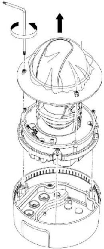
REMOVING DOME
- Use the supplied torx key to unscrew the three fastening points for the dome.
- Lift the dome to remove it from the camera chassis.
natural_image
Exploded view diagram of a mechanical device showing internal components and assembly (no text or labels)INSTALLING THE MICROSD CARD
Steps:
- Use the supplied hardware to unfasten the dome screws and remove the from the chassis.
- Insert the microSD card into the available reader slot.

INSTALLING THE CAMERA - CABLING ROUTED THROUGH BASE
Steps:
- Use a pencil and the mounting base to mark the drilling points and the cable hole on the installation surface.
- Drill the cable hole and anchoring points into the installation surface.
- Insert the anchors.
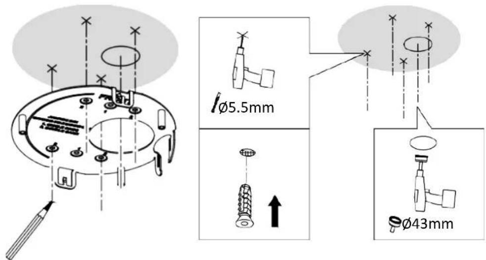
- Route the cabling harness through the center cable hole.
- Use a Philipps-head screwdriver to fasten the mounting base to the installation surface.

- Proceed to Installation – Preparing Camera Housing for next steps.
INSTALLING THE CAMERA — CABLING ROUTED THROUGH SIDE
Steps:
-
Run the cabling to the installation point.
-
Install the routing hole cap where you intend to insert the cabling harness into the side of the camera housing. (Front is marked on the mounting base). Ensure the hole cap meets flush with the mounting base.
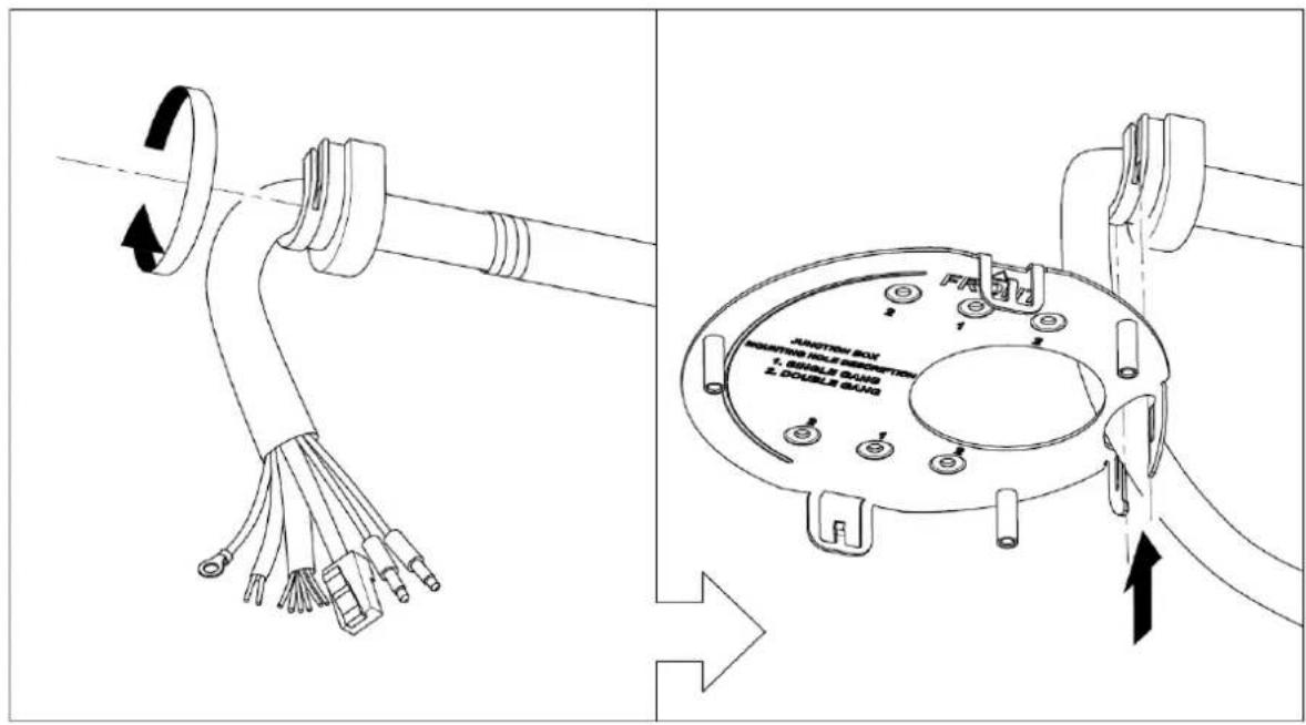
- Use a pencil and the mounting base to mark the drilling points on the installation surface.
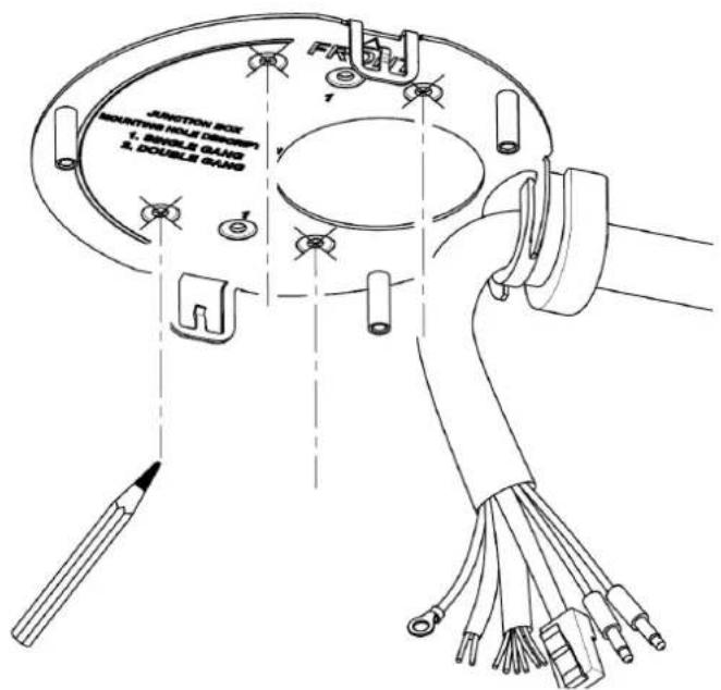
-
Drill the anchoring points into the installation surface.
-
Insert the anchors.

- Feed the cabling through the side routing hole as you bring the mounting plate closer to the installation surface. The routing hole cap should fit snuggly into place with the mounting plate. Use a Philips head screwdriver to fasten the mounting base to the installation surface.
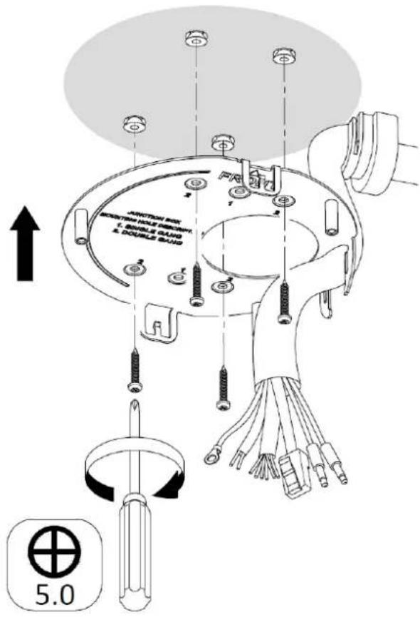
- Proceed to Installation – Preparing Camera Housing for next steps.
INSTALLATION – PREPARING CAMERA HOUSING
- If routing the cable through the base of the camera, route the cabling through the hole you drilled in the installation surface (A). If you are routing the cable through the side of the camera, no action is required (B).
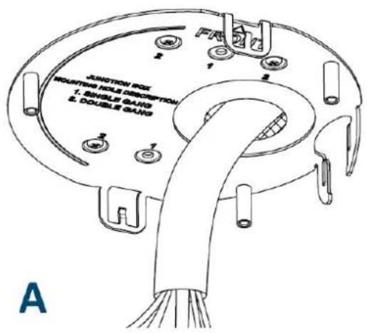

- Using a Philipps-head screwdriver, attach the GND wire to the grounding terminal located in the camera's housing

- Attach the supplied RJ-45 piercing cap to the RJ-45 cable head.
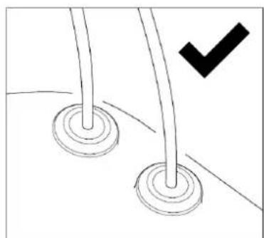
- Pierce the center weatherproof gasket seal and pull the RJ-45 cable through the gasket. Always pull the cabling through gently to avoid tearing the gasket.
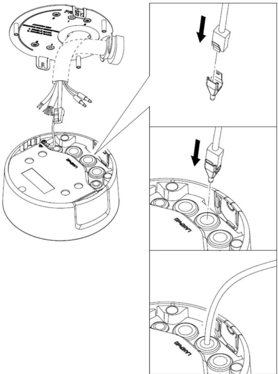
- Use the supplied Torx key to pierce the remaining seals and insert the remaining cabling through the weather seals.

Warning: Only pass a single segment of cabling through a seal. Attempting to pass more than one segment of cabling can compromise the seal.
natural_image
Simple line drawing of two circular objects with a black checkmark indicating a detail (no text or symbols)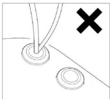
natural_image
Simple line drawing of a tool interacting with two circular components, one with a cross symbol (no text or labels)- If routing through the bottom of the camera, skip this step. If routing cabling through the side of the camera, remove the side routing hole plug from the camera housing and dispose of it.

natural_image
Diagram of a device with internal components and a recycling bin, showing a hand holding a clip (no text or symbols present)-
Pull the remaining cables through the weatherproof gaskets.. Always pull the cabling through gently to avoid tearing the gasket. Be sure to dispose of the RJ-45 piercing cap.
-
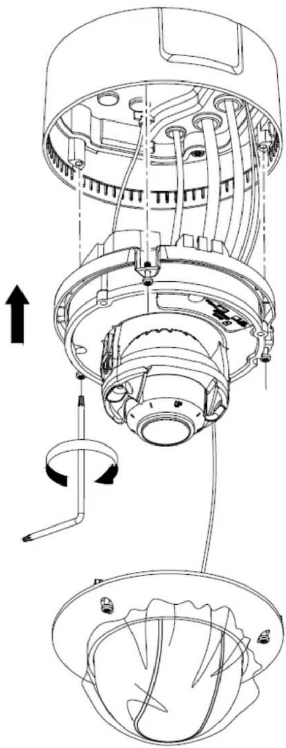
Fasten the camera housing to the mounting plate using the supplied Torx key.

- Attach the safety wire located in the camera housing to the clip located on the camera body.

natural_image
Technical diagram of an industrial robotic arm with internal components and wiring, showing assembly steps (no text or labels)-
Remove the alarm and power terminal blocks.
-
Wire the alarm and power blocks according to the labelling on the wiring / blocks.
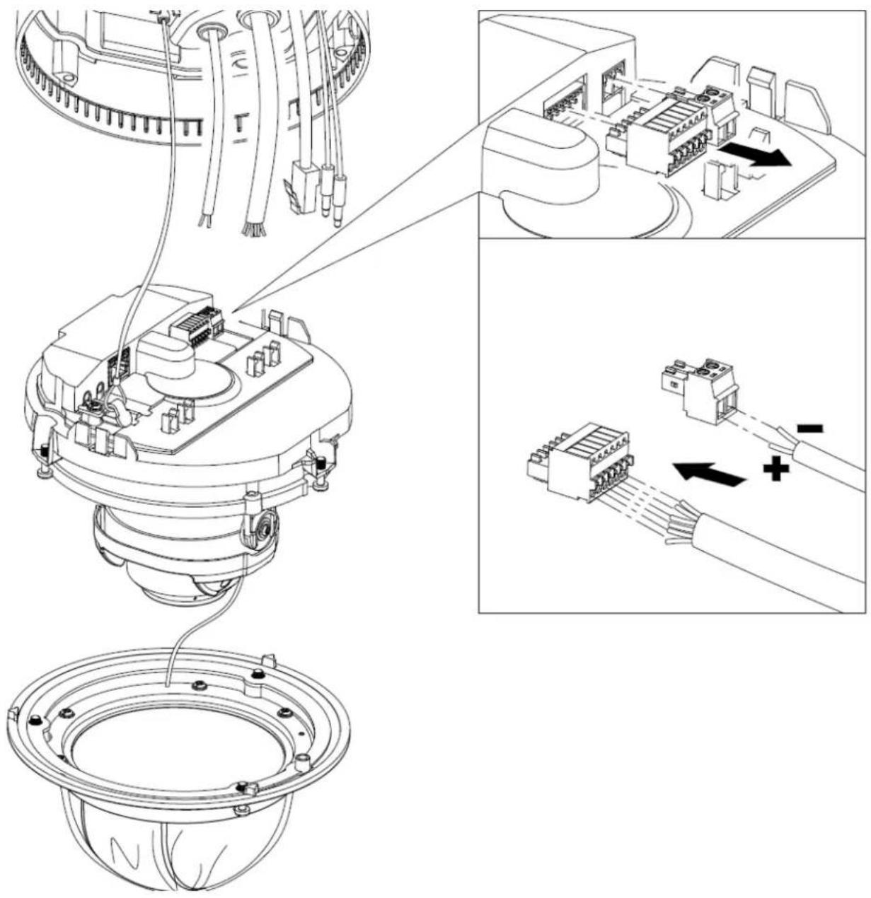
- Attach all cabling and blocks to the camera's inputs / outputs.

natural_image
Technical line drawing of a mechanical assembly with exploded and assembled views (no text or symbols)- Fasten the camera body to the camera housing using the supplied torx key,
- Fasten the dome to the camera body using the supplied torx key.
natural_image
Technical line drawing of a mechanical device with internal components and directional arrows indicating assembly (no text or symbols)2 Camera Setup
2.1 Detecting, Activating Changing the Camera IP Address
After networking the camera with the LAN, the user must obtain the camera's IP address to connect to the device. To obtain the IP address, the 3xLOGIC Camera (VISIC IP) Setup Utility, a software tool which can automatically detect online network cameras on the LAN, add these devices to VIGIL Server and list the device information including IP address, subnet mask, port number, device serial number, device version, etc... is recommended. An example is shown in Figure 2-3.
This utility is installed alongside VIGIL Server or can be downloaded separately. If on a VIGIL Server system, launch utility from Start>Programs>VIGIL>Utility or download the utility from the 3xLOGIC website's Software Support Center > VIGIL Utilities (http://www.3xlogic.com/software-center) to a Windows PC.
Steps:
- Launch the utility.
- Click Detect Online Devices / Change IP Address.
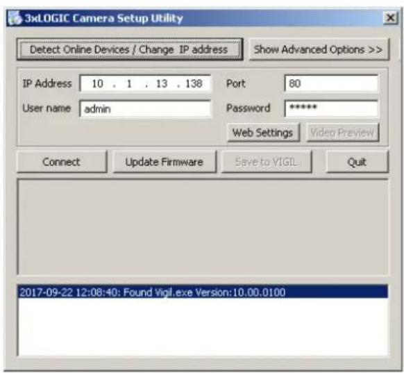
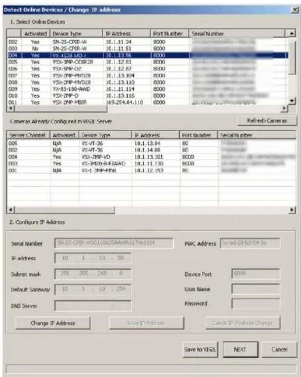
Figure 2-1 3xLOGIC Camera (VISIX IP) Setup Utility
- Select the camera from the list of online devices.
- If you are configuring the camera for initial setup, click Activate to assign a new password. This step is required for security purposes and must be completed before continuing. If the camera has previously been configured, skip to Step 5.
- Once you have assigned a new password to the camera, click Change IP Address and change the IP address and subnet mask to the same subnet as that of your computer. Save the settings.

Figure 2-2 3xLOGIC Camera (VISIX IP) Setup Utility – Changing Device IP Address
- Enter the IP address of network camera in the address field of the web browser to access the camera's web UI.
The default IP address is 192.0.0.64 and the port number is 8000.
NOTE: ■ For accessing the network camera from different subnets, please set the gateway for the network camera after you logged in.
1.1 Adding a VISIX S-Series Camera to VIGIL Server
Purpose:
By following the steps outlined in this section, a user can add a camera to VIGIL Server using the 3xLOGIC Camera (VISIX IP) Setup Utility. The utility was previously utilized in Section 2.1.2 to detect and change the camera's IP address. This utility is installed alongside VIGIL Server and will launch automatically when following the below steps.
Steps:
- Login to VIGIL Server.
- Open the Settings > Camera Setup Tab.
- Select an unused camera channel to associate with the camera.
- Toggle the Network Camera checkbox. The Network Camera Settings form will deploy. If the form does not deploy automatically, click the Network Camera - Settings button.
- Click the Detect Cameras button located next to the Type field. The 3xLOGIC Camera Setup Utility will deploy and will automatically begin detecting devices on the network.
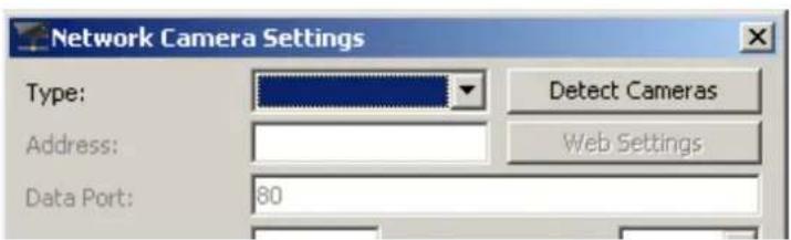
Figure 1-1 Launching the 3xLOGIC Camera Setup Utility
- Select the desired camera from the list of online devices and click Next.
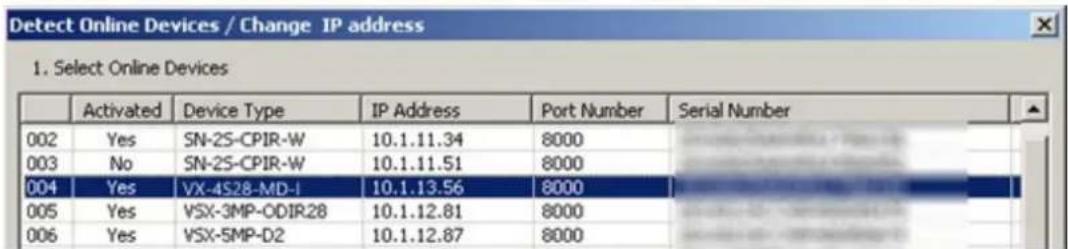
Figure 1-2 3xLOGIC Camera (VISIX IP) Setup Utility – Selecting Camera from Online Devices List
- After the utility successfully accesses the camera, click Save to VIGIL. A window will deploy where the user can assign the camera's stream profiles.
NOTE: If the utility fails to access the camera, confirm the utility is using the correct log-in credentials for the camera (created during camera activation) and re-attempt saving to VIGIL. If issues persist, contact 3xLOGIC Support.
![Save Camera to VIGIL Save to VIGIL Server camera number 7. IP Address: 10.1.11.189 User Name: admin Password: 12345 This camera has multiple streams available. Please select which streams to save to VIGIL. Main Stream: Stream 1 Sub Stream: Stream 2 Stream 1 URL: rftp://10.1.11.189/h264/ch1/main/av_stream Codec: H.264 resolution: 3MP[2048x1536] FPS: 8 Bitale: 1792K Stream 2 URL: rftp://10.1.11.189/h264/ch1/sub/av_stream Codec: H.264 resolution: QVGA[320x240] FPS: 15 Bitale: 320K OK Cancel](/content/2026/06/1219471/images/ab7764867d2ed9c91a6ce7f819f2816fe7cb015337b6720a03533b9230e079b9.jpg)
Figure 1-3 Assigning Stream Profiles
- Assign the streams as desired and click OK.
The user will be returned to the Network Camera Settings form.
- Configure additional settings as desired.

- Click OK to on the Network Camera Settings form then click Apply on the VIGIL Server Settings window to save the new settings.
The camera will now be saved to VIGIL and can be accessed and controlled via the VIGIL Server UI. Any other applicable VIGIL utilities (VIGIL Client, View Lite II) that have been interfaced with the VIGIL Server will also be able to access and control the camera. See the VIGIL Server and VIGIL Client User Guides for more information on interacting with the camera and its footage. Visit the 3xLOGIC Document Library for the latest available support documentation.
1.2 Access UI via Web Browser
Steps:
- Open a web browser.
- Input the IP address of the network camera in the URL address bar, e.g., 192.0.0.64 and press the Enter key to enter the login interface. Alternatively, if the camera is interfaced with VIGIL Server, the web UI can be instantly deployed by opening the camera's Network Settings form in VIGIL Server Settings > Cameras Tab and clicking the Web Settings button.
- Input the user name and password and click Login.
NOTE: The username/password for the camera will have been configured during camera activation If the camera has already been configured using one of 3xLOGIC's setup tools (VIGIL Easy Setup Wizard, 3xLOGIC Camera Setup Utility) then default credentials will have been changed by the installer (this is a standard security precaution enforced by the setup tools). Contact your security network administrator for credentials.
NOTE: English is the only supported language.
3xLOGIC
NETWORK CAMERAS
VISIX

admin

●●●●●●●
Login
Figure 2-3 Login Interface
- To view video and have full access to the camera's configuration settings, you will need to install the Web Components plug-in. Click "Activate Web Components" to start the plug-in installation.
NOTE: Depending on your web browser, you may be required to authorize the installer to run.
NOTE: You may have to close the web browser to install the plug-in. Reopen the web browser and log in again after installing the plug-in.

Figure 2-4 Download and Install Plug-in
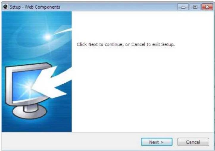
Figure 2-5 Install Plug-in (1)

Figure 2-6 Install Plug-in (2)
After the Web Components plugin successfully install, you can access and operate the camera's browser interface. Visit the 3xLOGIC Document Library for the latest available support documentation.
3xLOGIC
12000 Pecos St., Suite 290
Westminster, CO 80234
303.430.1969
Toll Free: 877.3xLOGIC
www.3xlogic.com
© 2019 3xLOGIC Inc. All rights reserved.
Information in this document is subject to change without notice. 3xLOGIC and the 3xLOGIC logo are trademarks of 3xLOGIC, Inc. all other trademarks are property of their respective owners.
Revised: July 3rd, 2019
- VISIX S-Series Outdoor IP Dome Camera
- Table of Contents
- CAMERA OVERVIEW....3
- CAMERA SETUP .... 16
- Camera Overview
- Package Contents
- AVAILABLE MOUNTS
- Installation
- REMOVING DOME
- INSTALLING THE MICROSD CARD
- Steps:
- INSTALLING THE CAMERA - CABLING ROUTED THROUGH BASE
- INSTALLING THE CAMERA — CABLING ROUTED THROUGH SIDE
- INSTALLATION – PREPARING CAMERA HOUSING
- Camera Setup
- Detecting, Activating Changing the Camera IP Address
- Adding a VISIX S-Series Camera to VIGIL Server
- Purpose:
- Access UI via Web Browser
- 3xLOGIC
Brand : 3xLOGIC
Model : VX-2M-OD3-RIAH
Category : Security Camera