
915 - Desktop Computer In Win - Free user manual and instructions
Find the device manual for free 915 In Win in PDF.


| Brand | In Win |
| Model | 915 |
| Product Type | Desktop Computer Case |
| Form Factor | Mid Tower |
| Motherboard Compatibility | ATX, Micro-ATX, Mini-ITX |
| Dimensions (W x H x D) | 200 x 450 x 480 mm |
| Weight | 7.5 kg |
| Material | SECC Steel, Plastic Front Bezel |
| Color | Black |
| Drive Bays | 4 x 3.5", 2 x 2.5" (internal), 2 x 5.25" (external) |
| Expansion Slots | 7 |
| Cooling Support | Front: 2 x 120mm / 140mm fans; Rear: 1 x 120mm fan; Top: 2 x 120mm fans |
| I/O Ports | USB 3.0 x 2, USB 2.0 x 2, HD Audio (Mic & Headphone) |
| Power Supply Type | Standard ATX PSU (not included) |
| Maximum GPU Length | 330 mm |
| Maximum CPU Cooler Height | 160 mm |
| Included Accessories | User Manual, Screw Set, I/O Shield |
| Cleaning | Wipe with a dry, lint-free cloth. Avoid liquid cleaners. |
| Safety | Keep away from liquids and heat sources. Ensure proper ventilation. |
| Warranty | 1 Year Limited Warranty |
Frequently Asked Questions - 915 In Win
User questions about 915 In Win
0 question about this device. Answer the ones you know or ask your own.
Ask a new question about this device
Download the instructions for your Desktop Computer in PDF format for free! Find your manual 915 - In Win and take your electronic device back in hand. On this page are published all the documents necessary for the use of your device. 915 by In Win.
USER MANUAL 915 In Win
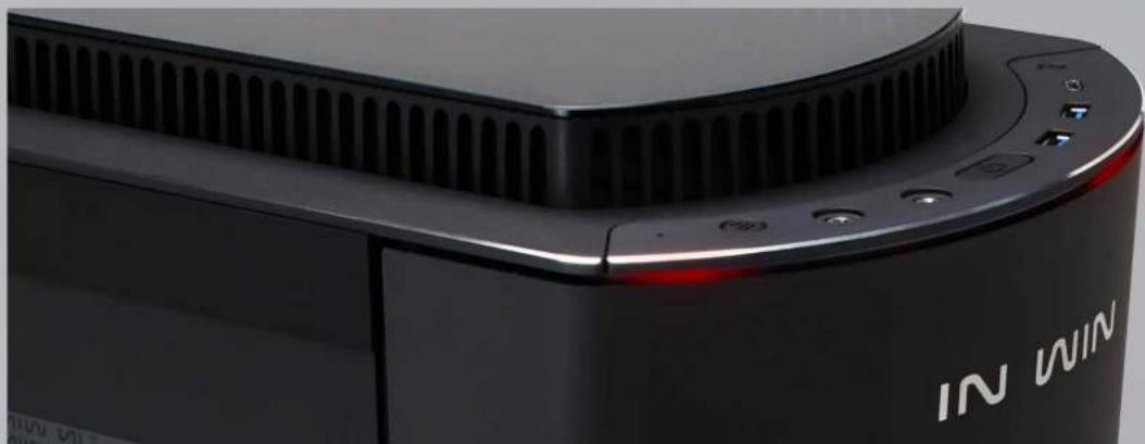
The InWin 915 joins the 9-series lineup of elegant aluminium and tempered glass cases, but with a twist! Our goal is to provide a new and unique product to match with the overall flare of the 9-series, and the 915 covers that description perfectly.

Specifications
| Model 915 | |
| Part Number IW-915-Black / IW-915-Silver | |
| Colors Black/Silver | |
| Case Type Full Tower | |
| Materials Aluminium, Tempered Glass, ABS, SECC | |
| M/B Compatibility 12" x | 13.5" E-ATX, ATX, Micro-ATX, Mini-ITX |
| Expansion Slots | PCI-E x 8Vertical PCI-E x 2 (Riser Card Optional, Not Included in Package) |
| Maximum Compatibility | VGA Card Length: 410mm (Maximum)VGA Card Width: 168mm (Maximum)Vertical Display VGA Card Height: 50mm (Maximum)CPU Heatsink Height: 164mm |
| Front Ports | 1 x USB 3.1 Gen 2 Type-C2 x USB 3.0HD AudioTop Cover Ventilation & LED Lighting Control Switch |
| Internal Drive Bays | 4 x 2.5"/3.5" (Bottom Drive Bay Trays)5 x 2.5" (4 Brackets and 1 Mounting Area on Motherboard Tray)4 x 2.5" (Multifunctional Fan Bracket Mounts)Max Drive Support: 13 x 2.5" Drives or4 x 3.5" Drives and 9 x 2.5" Drives |
| Thermal Solution Compatibility | 3 x 120/140mm Front Fans / 280/360mm Radiator(280mm Radiator Height up to 53mm, 360mm Radiator Heightup to 56mm)1 x 120mm Rear Fan / 120mm Radiator3 x 120/140mm Top Fans / 280/360mm Radiator(Height up to 70mm)2 x 120/140mm Bottom Fans / 240/280mm Radiator |
| Power Supply Compatibility | PSII: ATX12V- 250mm Mounting Area(Length up to 320mm when Two HDD Cages Removed) |
| Product Dimensions (H x W x D) | 570 x 230 x 645 mm22.44" x 9.06" x 25.4" |
| Product Dimensions with Top Raised (H x W x D) | 595 x 230 x 645 mm23.43" x 9.06" x 25.4" |
| Package Dimensions (H x W x D) | 740mm x 392mm x 792mm29.14" x 15.44" x 31.18" |
| Net Weight 16.4kg / 36.2lb | |
| Gross Weight 19.8kg / 43.7lb | |
* Our products comply with RoHS regulation.
* Specifications may vary based on different regions.
* Extra fee for optional parts.
Package Contents

1.915 Chassis
2.QR Code Card

Package Contents

3. Accessories Bag

a. Motherboard Stand-offs x11
b. Motherboard Stand-off Socket x1


c.Hexagon Head Screws x18
d.2.5" SSD Screws x36

e. Cable Ties x10

f.Water-cooling System Washers x24

g. Graphics Card Holders x2
h.Pin Header x1


i. Wire Mounts x3
j.Riser Card x1 (Optional)
k. Riser Card Stand-offs x2 (Optional)
- Riser Card Screws x2 (Optional)
Case Structure


| 1 | Top Cover Ventilation | e | USB 3.0 Ports |
| 2 | I/O Panel | f | USB 3.1 Gen 2 Type-C Port |
| a | HDD/Power LED Indicator | g | Reset Button |
| b | Top Cover Ventilation & LED Lighting Control Switch | 3 | Tempered Glass Side Panels |
| c | Audio Ports (Earphone and Microphone) | 4 | Aluminium Curved Front Panel |
| d | Power Button | 5 | Aluminium Curved Back Panel, Wire Routing Hole |
Case Structure

Length up to 320mm when two HDD cages removed
| 1 | 2.5"/3.5" Drive Bay 9 Motherboard Mounting Area | |
| 2 | 2.5" Drive Bay 10 | |
| 3 | Power Supply Mounting Area 11 PC | - E Expansion Slot |
| 4 | Top Cover Ventilation 12 | |
| 5 | Top Fan/ Radiator Mounting Area 13 | Extra PCI-ESupporting Mounting Hole |
| 6 | Front Fan/ Radiator Mounting Area 14 | Fan Dust Filter |
| 7 | Rear Fan/ Radiator Mounting Area 15 | Shock-Proof Stand |
| 8 | Bottom Fan/ Radiator/2.5" Drive Mounting Area | |
Case Structure


| 1 | 2.5"/3.5" Drive Bay 9 Motherboard Mounting Area | |
| 2 | 2.5" Drive Bay 10 | |
| 3 | Power Supply Mounting Area 11 PC | - E Expansion Slot |
| 4 | Top Cover Ventilation 12 | |
| 5 | Top Fan/ Radiator Mounting Area 13 | Extra PCI-ESupporting Mounting Hole |
| 6 | Front Fan/ Radiator Mounting Area 14 | Fan Dust Filter |
| 7 | Rear Fan/ Radiator Mounting Area 15 | Shock-Proof Stand |
| 8 | Bottom Fan/ Radiator/2.5" Drive Mounting Area | |
Installation Guide
* Please follow the related chapters to assemble.
* Please use original provided accessories to avoid damage to the product.

1. Opening the Chassis
For the tempered glass side panel, please remove by pulling the gray tab forward.

2. Power Supply Installation

Parts Required: Hexagon Head Screws
Please check the size of your power supply. You can remove the divider and 3.5" drive bays for extra installation space.
Power supply must be mounted at the bottom of the chassis.

Installation Guide

3. Motherboard Installation
Parts Required: Motherboard Stand-offs, Motherboard Stand-off Socket, Hexagon Head Screws


4. Expansion Card Installation
Parts Required: Hexagon Head Screws, Graphics Card Holders, Mylar After user installs the graphic card, use the graphic card holder to secure it. If more than one graphic card is needed, please stick the Mylar on the bottom side of the holder to prevent damages caused by metal contacts.


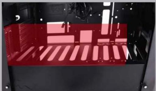
Parts Required: Riser Card (Optional), Riser Card Stand-offs (Optional), Riser Card Screws (Optional) Please remove all bottom fan brackets before installing the riser card and graphics card.
Installation Guide
5. I/O Wires Installation

RESET SW
POWER SW
H.D.D. LED
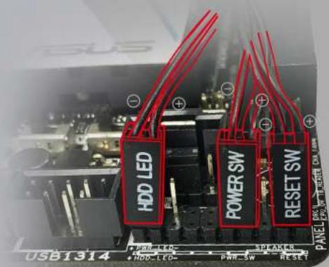
POWER SW RESET SWH.D.D. LED
HD Audio Source Connector

PORT2_L
BLUE 10
SENSE_SEND PURPLE 8
PORT2_R YELLOW6
PORT1 R RED 4
PORT1_L GREEN2

9 BROWN SENSE2_R
7 KEY
5WHITE SNSE1_R
3 ORANGEPRESENCE#
1 BLACK GND
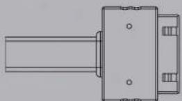
USB3.0 Connector

Installation Guide
6-1. Addressable RGB Light Bar Operation Instructions
If your motherboard support the addressable RGB luminous effect, please follow the direction of sign and insert addressable RGB-strip into the 3-pin addressable RGB-strip header directly on the motherboard.

6-2. The Instructions of Type-C Cable
If your motherboard supports Type-C, please connect the Type-C connector with the header directly on the motherboard.


Installation Guide
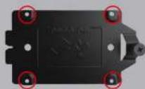
7-1. 2.5" Drive Bays Installation
Parts Required: 2.5" SSD Screws

7-2. 3.5" Drive Bays Installation


Please unscrew the thumbscrews and remove the 2.5" drive bays.
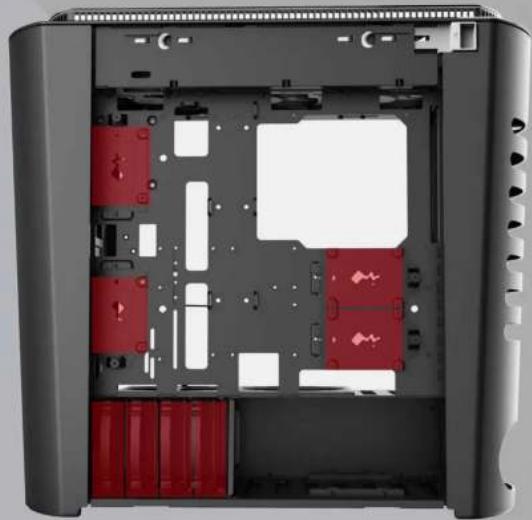
Pull out the 3.5" drive bays.

Install 2.5" SSD into the drive bay and screw it back to the proper mounting area.

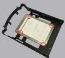

3.5" HDD Screwless2.5"SSD


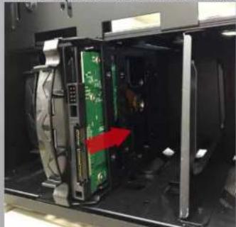
Push the tray back Push the tray back
Install 3.5" HDD into the drive bay and push it back, the drive bays are reversible and allow users to mount in either direction. (A 2.5" SSD can be mounted also.)
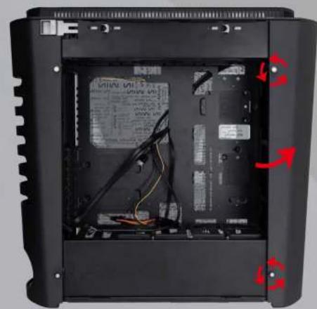
8. Front Fan/ Liquid Cooling Radiator Installation

Parts Required: Water-cooling System Washers
Open the front panel by loosening the thumbscrews on the side, then take out the fan bracket and install the fans/radiator.


Installation Guide
9. Top Fan/ Liquid Cooling Radiator Installation

Parts Required: Water-cooling System Washers
Open the back panel by loosening the thumbscrews on the side.
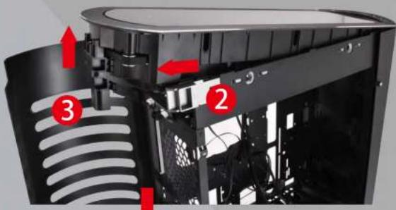
Take out the fan bracket and install the fans/radiator. (Note* Be cautious of pressing or pulling any of the internal wires, which may result in wire failures. Please run the wires smoothly before installing the top cover.)

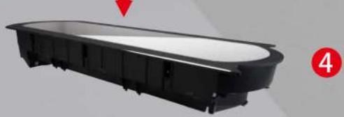
Please unscrew the thumbscrew under the top cover. Pull out the top cover horizontally and lift upwards to remove the cover.


10. Rear Fan/ Liquid Cooling Radiator Installation

Parts Required: Water-cooling System Washers
Open the back panel (refer to step 9) and install the fans/radiator.
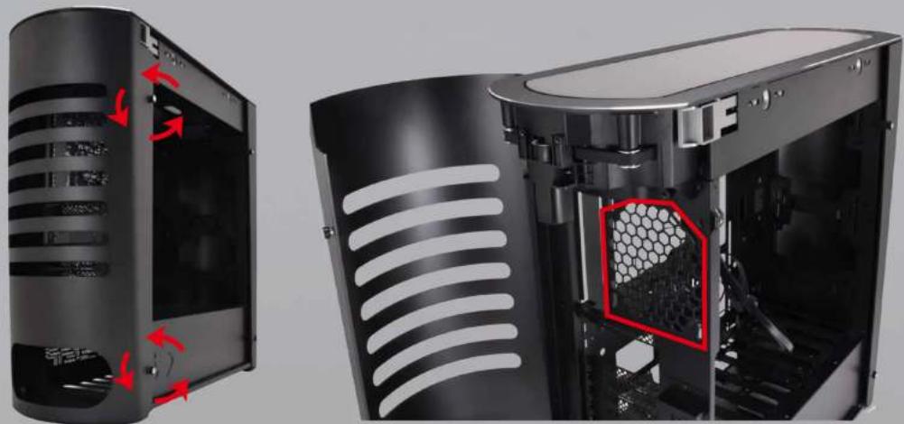
For the convenience of installation, the 915 allows users to completely remove the front and back panel. To easily remove the panels, please refer to step 9 to remove the top cover, and lift the panel upward off the hinge to completely remove the front or back panel.
Installation Guide
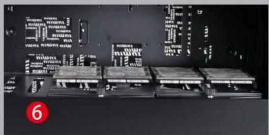
11. Bottom Fan/ Liquid Cooling Radiator Installation
Parts Required: Water-cooling System Washers
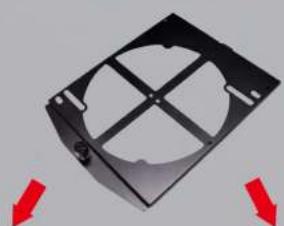
Take out the fan bracket and install the fans/radiator (4 x 2.5" SSDs can be mounted if preferred.)


4


12. Completing Installation
Parts Required: Cable Ties

Lighting Modes
The 915 will automatically display the lighting effects in the front panel for 10 seconds when computer turns on, then will lead users into two lighting modes. (The lighting modes depend on the features of the motherboard.) This allows users to switch between:
1. InWin LED (Default Mode)
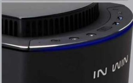
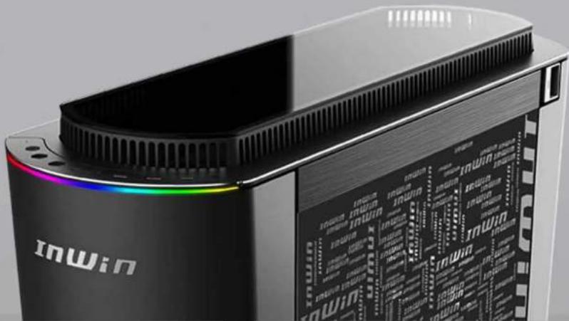
The InWin LED mode comes with 13 distinct lighting effects. If your motherboard doesn't feature addressable headers, the lighting will be placed on InWin LED mode. In this mode, you can still switch to different colors such as: red, green, blue, white and multicolor to your personal preference, and display 13 distinctive lighting effects with a variety of luminous styles.



2.Addressable RGB
If your motherboard supports addressable RGB headers, please connect the 3-pin addressable cable directly to the motherboard (refer to step), it allows you to sync the addressable lighting effects with motherboard.
Lighting Control
- The lighting effects are controlled by pressing the Top Cover Ventilation & LED Lighting Control button. To switch between InWin LED mode and Addressable RGB, just simply hold the button for 2 seconds. (Note* The top cover ventilation control and system failure indicator will be temporarily unavailable.)
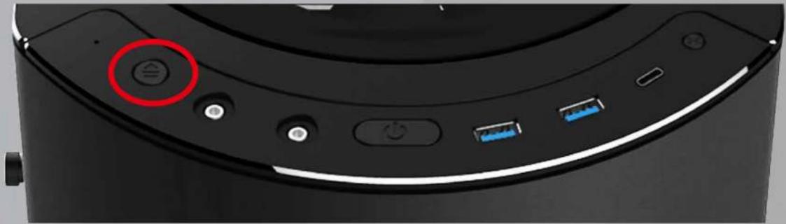
- When switching from Addressable RGB to the InWin LED mode, it also can shift to different LED lighting effects by a quick press of the button, the button sequence is as follows:
| Button Presses | LED Modes Color | ||
| 1 |  Breathing Breathing | Red | |
| 2 Green | |||
| 3 Blue | |||
| 4 White | * | ||
| 5 |  Double-SidedScrolling Double-SidedScrolling | Red | |
| 6 Green | |||
| 7 Blue | |||
| 8 White | * | ||
| 9 |  MiddleScrolling MiddleScrolling | Red | |
| 10 Green | |||
| 11 Blue | |||
| 12 White | * | ||
| 13 Multicolor Mul |  | ||
To turn off the lights directly, just hold the button for 5 seconds.
* The white featured in the InWin LED mode will be displayed as RGB white instead of pure white.
-
The operation will be considered complete if there is no activity for 6.5 seconds.
-
Once the setup has completed, the features of top cover ventilation control and system failure indicator will resume normal operation.
Note* The current settings of lighting effect will be saved if you turn off the computer in the proper way. You can have your previous lighting settings automatically when reboot the computer. But it will return to factory settings if your computer is in a power off condition such as: the electricity goes out suddenly, or turning off the power switch before the computer shutting down.
Troubleshooting
- When the system failure indicator LED is flashing on both sides, please check for any of the following occurrences:
| System Failure Indicator | Color | Occurrence Description | |
| Flashing on Both Sides | Red | A Malfunction of the Motor or the Top Cover | The motor stops running, or the top cover isn’t installed properly. |
| Green | A Malfunction of the Switch or the Wires | The limit switch or the internal wires are broken or damaged. | |
| Blue | Stuck with a Foreign Object | Insufficient space for top cover lift, or the top cover is stuck due to a foreign object. | |
| White | Overweight | Do not stack anything on the top cover to avoid any damages. |
If an error occurred, please press the top cover ventilation switch to reopen the cover after troubleshooting.
-
If the elevating ventilation cover isn't lifting up/down automatically when computer turns on/off, please refer to step 1 to check if there are any problems, then press the top cover ventilation switch to control the lifting system manually. Please do not press or pull out the top cover by force.
-
If the power goes off, the top cover will lift down after the power supply is restored. Please press the top cover ventilation switch to reset the lifting system.
Notices and Warranty
Notices
- Please follow the user manual for installation.
- To avoid damaging any circuits, please make sure the power is off before assembling the top cover.
- When installing the computer components, please use the antistatic precautions to prevent ESD (electrostatic discharge) damage. This can cause injury to the installer and/or damage to the machine. Incorrect installation may burnout the motherboard and other system components.
- Do not stack anything on the top cover. To avoid any damages, do not exceed weight limitation and please handle with care.
- When the top cover, front/ back/ side panels are opened, please do not put your hands or other objects into the fans or other parts in operation. And please make sure to keep away from children and pets.
- Please avoid unnecessary insertions and extractions to the addressable cable as it may damage the pins.
- To avoid any damages, please do not use this product for any other purpose than its intended use.
8.Any modifications may damage the product. - Please remove all internal devices before shipping or moving. (Including power supply, hard drives, motherboard, CPU, etc)
Warranty
* For more detailed warranty information, please visit the InWin retail website at www.in-win.com.
* The actual product is subject to change without prior notice. InWin Development Inc. reserves the right to make any final modificat

InWin
CONTEMPORARY & INNOVATIVE
www.in-win.com
Copyright © 2018 In Win Development Inc. All Rights Reserved.


- SPECIFICATIONS
- PACKAGE CONTENTS
- ACCESSORIES BAG
- CASE STRUCTURE
- INSTALLATION GUIDE
- OPENING THE CHASSIS
- POWER SUPPLY INSTALLATION
- MOTHERBOARD INSTALLATION
- EXPANSION CARD INSTALLATION
- I/O WIRES INSTALLATION
- 6-1. ADDRESSABLE RGB LIGHT BAR OPERATION INSTRUCTIONS
- 6-2. THE INSTRUCTIONS OF TYPE-C CABLE
- 7-1. 2.5" DRIVE BAYS INSTALLATION
- 7-2. 3.5" DRIVE BAYS INSTALLATION
- FRONT FAN/ LIQUID COOLING RADIATOR INSTALLATION
- TOP FAN/ LIQUID COOLING RADIATOR INSTALLATION
- REAR FAN/ LIQUID COOLING RADIATOR INSTALLATION
- BOTTOM FAN/ LIQUID COOLING RADIATOR INSTALLATION
- COMPLETING INSTALLATION
- LIGHTING MODES
- INWIN LED (DEFAULT MODE)
- 2.ADDRESSABLE RGB
- LIGHTING CONTROL
- TROUBLESHOOTING
- NOTICES AND WARRANTY
- NOTICES
- WARRANTY
Brand : In Win
Model : 915
Category : Desktop Computer