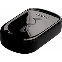
DPR-1040 - Printer D-LINK - Free user manual and instructions
Find the device manual for free DPR-1040 D-LINK in PDF.


| Product Type | Wireless Print Server |
| Dimensions | 4.5 x 3.1 x 1.2 in (114 x 79 x 30 mm) |
| Weight | 0.22 lbs (100 g) |
| Power Supply | 5V DC, 2A |
| Wireless Standard | IEEE 802.11g/b |
| USB Port | 1 x USB 2.0 Type A |
| Network Protocols | TCP/IP, IPX, NetBEUI |
| Supported OS | Windows 2000/XP/Vista/7, Mac OS 9/X, Linux |
| Wireless Security | WEP 64/128-bit, WPA, WPA2 |
| LED Indicators | Power, Link/Act, USB |
| Buttons | Reset, WPS |
| Operating Temperature | 0 to 40°C (32 to 104°F) |
| Humidity | 10 to 85% (non-condensing) |
| Package Contents | Print server, power adapter, setup CD, quick installation guide, RJ-45 cable |
| Warranty | 1 year limited |
| Certifications | FCC, CE, Wi-Fi |
| Maintenance | Clean with a dry, soft cloth. Keep away from moisture and extreme temperatures. |
| Safety | Use only the provided power adapter. Do not disassemble or expose to water. |
| Repairability | No user-serviceable parts. Contact D-Link support for repairs. |
Frequently Asked Questions - DPR-1040 D-LINK
User questions about DPR-1040 D-LINK
0 question about this device. Answer the ones you know or ask your own.
Ask a new question about this device
Download the instructions for your Printer in PDF format for free! Find your manual DPR-1040 - D-LINK and take your electronic device back in hand. On this page are published all the documents necessary for the use of your device. DPR-1040 by D-LINK.
USER MANUAL DPR-1040 D-LINK
Rev. 04 (January, 2009)
D-Link®
Building Networks for People
Table of Contents
Package Contents.... 1
Contents of Package: 1
System Requirements: 1
Introduction....2
External Features .... 4
Rear Panel 4
USB Port 4
Ethernet Port (LAN) 5
DC Power Connector 5
Wi-Fi Protected Setup (WPS) Button 5
LED Indicators....6
Wireless Basics 8
Wireless Installation Considerations.... 10
Installing Considerations 10
WPS (Wi-Fi Protected Setup).... 12
Setting up the DPR-1040 13
Installing the Print Server 13
Wireless Setup.... 14
Getting Started 16
Using PS Software 17
Auto-Run Installation 17
Installing PS Software 18
Using PS-Link.... 20
Installing and Using MFP/GDI Printers 26
Using the Web Configurator 44
Table of Contents
HOME.... 44
SETUP > Print Server Setup.... 46
SETUP > LAN Setup....48
SETUP > Wireless Setup 49
SETUP > Printer Setup 51
ADVANCED > Advanced LAN 55
ADVANCED>User Access....56
MAINTENANCE > Password.... 58
MAINTENANCE > Save/Restore Settings.... 59
MAINTENANCE > Firmware Upgrade.... 60
MAINTENANCE > Diagnostics 61
STATUS > Device Info.... 62
STATUS > Network.... 64
STATUS > Wireless 65
HELP 66
Reboot.... 67
Refresh Printer Status 68
TCP/IP Printing for Windows Vista.... 69
TCP/IP Printing for Windows XP.... 77
TCP/IP Printing for Windows 2000 92
Setting up Printing in Mac OS X Tiger (10.4.9).... 105
Adding a Printer.... 105
To set up LPD Printing 107
Set up Socket Printing.... 108
Technical Specifications 111
Contacting Technical Support.... 112
Warranty and Registration 113
Table of Contents
Appendix: DPR-1040 Printer Compatibility List 120
Package Contents

Contents of Package:
■ D-Link DPR-1040 USB 2.0 Wireless 11g MFP Server
■ Manual and Warranty on CD
■ Printed Quick Installation Guide
If any of the above items are missing, please contact your reseller.
System Requirements:
A computer with Ethernet interface
Windows Vista/XP/2000/NT4/ME/98SE
■ MAC OS X 10.4.x
- Internet Explorer 6.0 or above; Netscape Navigator version 6.0 or above, with JavaScript enabled
- Your printer must support the required operating system
Introduction
D-Link's DPR-1040 Print Server allows you to connect a USB Multi-Function Printer (MFP) to your existing Ethernet network. This product lets multiple users print, scan and fax using the connected printer. The DPR-1040 also manages the flow of print files and delivers print jobs quickly and efficiently.
The DPR-1040 comes with easy to use software compatible with most Windows-based networks. Protocol support for TCP/IP, LPR, RAW, IPP is provided to ensure seamless connection to major networking operating systems.
The DPR-1040 has a built in web configurator that allows users to easily configure the Print Server and manage multiple print queues through TCP/IP.
The DPR-1040 improves upon network printing services in the following ways:
The DPR-1040 manages the print file traffic for all of the connected printers. This provides relief for your file servers and allows them to be used to their full capacity for file access or other network services. On peer-to-peer networks, workstations can print directly to the Print Server without increasing the load of another workstation or server.
The DPR-1040 Print Server is portable and cheap compared to a PC-based print server. This means you're able to deploy the DPR-1040 in locations that offer maximum convenience to users.
Use the included PS-Link software to enable your computer to use your MFP printer's print/scan/fax/copy functions. PS-Link helps you to install your printer's
Introduction
manufacturer drivers without creating a physical USB connection from your printer to your computer. After the software provided by your printer's manufacturer is installed, using the printer's scan and fax functions will be exactly the same as how it's described in your printer's manual.
The DPR-1040 is compatible with the following major network operating systems:
TCP/IP
UNIX Ipr/lpd (HP-UX, SunOS, Solaris, SCO, UnixWare, IBM AIX) Windows NT/2000, Windows 98SE/ME, Windows XP/Vista, NetWare 5.x NDPS LPR Remote Printing
MacOS X (LPR/IPP protocols)
The PS software - PS Link, allows further configuration of the MFP server:
■ PS-Link — Use this to enable your computer to use your printer’s print/scan/fax/copy functions and GDI printing. PS-Link helps you to install your printer’s manufacturer drivers without creating a physical USB connection from your printer to your computer. For more information see the “Using The PS Software” Chapter.
External Features
Rear Panel

USB Port
The DPR-1040's USB printer port is located on the rear panel of the device and is configurable using the web configurator.
The default IP address of the DPR-1040 is automatically acquired from a DHCP server on the network. If a DHCP server cannot be found the default IP address for the DPR-1040 will be 192.168.0.10.
NOTE: Your PC's IP Address must be in the same subnet as the Print Server's IP Address for the two devices to communicate. (For example, if MFP server's IP Address is 192.168.0.10, with a subnet mask of 255.255.255.0, then your computer's IP Address should be 192.168.0.x, where x is a value between 1-254,
excluding 10.)
Ethernet Port (LAN)
The Print Server's rear panel features an Ethernet port for connecting 10/100Mbps CAT 5 Ethernet cables. This port supports the NWay protocol, allowing the Print Server to automatically detect or negotiate the transmission speed of the network.
DC Power Connector
The DC power input connector is labeled DC 5V.
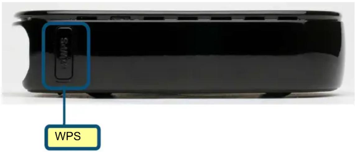
Wi-Fi Protected Setup (WPS) Button
Press this button to use WPS to connect to a wireless network. For more information about this button see Section 5 - Wireless Setup.
LED Indicators

The top of the Print Server features four LEDs:
Power

A steady blue light confirms that the Print Server is turned ON.
USB

A steady blue light indicates the printer is online and successfully connected to the print server. This light will also blink to indicate that data is being transferred between the print server and printer.
Link/Act

A steady blue light confirms that the Print Server has a connection to an Ethernet network. This light will also blink when receiving or transmitting data on the network.
WirelessLink/Act
A steady blue light confirms that the Print Server has a connection to a wireless network. This light will also blink when receiving or transmitting data on the network.
Wireless Basics
D-Link wireless products are based on industry standards to provide easy-to-use and compatible high-speed wireless connectivity within your home, business or public access wireless networks. D-Link wireless products allow you to access the data you want, when and where you want. You will be able to enjoy the freedom that wireless networking brings.
A wireless LAN (WLAN) is a cellular computer network that transmits and receives data with radio signals instead of wires. WLANs are used increasingly in both home and office environments, and public areas such as airports, coffee shops and universities. Innovative ways to utilize WLAN technology are helping people to work and communicate more efficiently. Increased mobility and the absence of cabling and other fixed infrastructure have proven to be beneficial for many users.
Wireless users can use the same applications they use on a wired network. Wireless adapter cards used on laptop and desktop systems support the same protocols as Ethernet adapter cards.
People use wireless LAN technology for many different purposes:
Mobility
Productivity increases when people have access to data in any location within the operating range of the WLAN. Management decisions based on real-time information can significantly improve worker efficiency.
■ Low Implementation Costs
WLANs are easy to set up, manage, change and relocate. Networks that frequently change can benefit from WLANs ease of implementation. WLANs can operate in locations where installation of wiring may be impractical.
■ Installation and Network Expansion
Installing a WLAN system can be fast and easy and can eliminate the need to pull cable through walls and ceilings. Wireless technology allows the network to go where wires cannot go – even outside the home or office.
Scalability
WLANs can be configured in a variety of topologies to meet the needs of specific applications and installations. Configurations are easily changed and range from peer-to-peer networks suitable for a small number of users to larger infrastructure networks to accommodate hundreds or thousands of users, depending on the number of wireless devices deployed.
Inexpensive Solution
Wireless network devices are as competitively priced as conventional Ethernet network devices.
■ Standards-Based Technology
Based on the IEEE 802.11g standard, the DPR-1040 is interoperable with existing compatible 2.4GHz wireless technology with data transfer speeds of up to 54Mbps when used with other D-Link devices.
■ Maximum wireless signal rate based on IEEE Standard 802.11g specifications. Actual data throughput will vary. Network conditions and environmental factors, including volume of network traffic, building materials and construction, and network overhead lower actual data throughput rate.
Wireless Installation Considerations
Installing Considerations
The D-Link DPR-1040 lets you print through your network, using a wireless connection, from virtually anywhere within its operating range. Keep in mind, however, that the number, thickness and location of walls, ceilings, or other objects that the wireless signals must pass through, may limit the range. Typical ranges vary depending on the types of materials and background RF (radio frequency) noise in your home or business. The key to maximize wireless range is to follow these basic guidelines:
- Keep the number of walls and ceilings between the DPR-1040 and other network devices to a minimum. Each wall or ceiling can reduce your D-Link wireless products range from 3-90 feet (1-30 meters). Position your devices so that the number of walls or ceilings is minimized.
- Be aware of the direct line between network devices. A wall that is 1.5 feet thick (0.5 meters), at a 45-degree angle appears to be almost 3 feet (1 meter) thick. At a 2-degree angle it looks over 42 feet (14 meters). Position devices so that the signal will travel straight through a wall or ceiling (instead of at an angle) for better reception.
- Building materials can impede the wireless signal. A solid metal door or aluminum studs may have a negative effect on range. Try to position wireless devices and computers with wireless adapters so that the signal passes through drywall or open doorways and not other materials.
Wireless Installation Considerations
- Keep your product away (at least 3-6 feet or 1-2 meters) from electrical devices or appliances that generate extreme RF noise.
WPS (Wi-Fi Protected Setup)
Wi-Fi Protected Setup (WPS) is a standard for easy and secure establishment of a wireless network. Traditionally, users would have to manually create a wireless network name (SSID), and then manually entering a creative, yet predictable security key on both the access point and client to prevent unexpected access to their wireless network.
This whole process requires the users to have the background knowledge of the Wi-Fi devices and the ability to make the necessary configuration changes. With WPS, it will automatically configure a wireless network with a network name (SSID) and strong WPA data encryption and authentication. WPS is designed to support various Wi-Fi certified 802.11 products including access points, wireless adapters, Wi-Fi phones, and any other consumer electronics devices.
For DPR-1040, WPS can be enabled by way of PBC (Push button configuration) method, in which users simply need to push a WPS button on both WPS devices to connect.
Setting up the DPR-1040
Installing the Print Server
WARNING: There may be configuration problems if the Print Server is turned on without first establishing a network connection.
Follow the steps below to avoid any complications during the hardware installation:
- Confirm that the printer you will use to connect to the DPR-1040 is operating correctly.
- When you have confirmed that the printer is operating correctly, switch its power OFF.
- Confirm that your network is operating normally.
- Using a CAT 5 Ethernet cable, connect the DPR-1040 Ethernet Port (labeled LAN) to the network.
- While the printer is turned OFF, connect the USB printer cable to the printer and then to the USB port on the Print Server.
- Switch on the printer.
- Insert the power adapter's output plug into the DC 5V power socket on the rear panel of the Print Server.
- Connect the other end of the power adapter into a power outlet. This will supply power to the Print Server. The blue LED on the Print Server's front panel should turn on.
Wireless Setup
WPS (Push Button Configuration)
WPS simplifies the process of connecting to a wireless network to a touch of a button. To use WPS you must have a WPS compatible wireless router, if you do not then you will need to manually configure the wireless connection in the web configurator (see Web Configurator below).
- After following the hardware installation steps in section 3, ensure your wireless network is operating normally. When ready, press the WPS button located on the side of the DPR-1040. The blue LED should start flashing repeatedly.
- Within 120 seconds, press the WPS button located on the wireless router you will be connecting to. This button may also be located in the router's web configuration pages labeled "Push Button Configuration (PBC)".
- If successful, a wireless connection will be established between the two devices. This connection is secure and uses automatically generated encryption keys; you do not need to remember them.
Note: If you experience problems connecting to a device, please try again. If you still experience problems, the device you're connecting to may be incompatible with the DPR-1040. Also, make sure you are connecting to a router or access point (AP).
Web Configurator
- After following the hardware installation steps in section 3, ensure your wireless network is operating normally. When ready, type the IP address of the DPR-1040 into your browser, the default IP address is 192.168.0.10. If this does not work, use the PS-Link utility to find out the IP address.
- Upon accessing the web configurator, click Setup > Wireless Setup.
- On the next screen, enter the wireless network settings as provided by your network administrator.
- Click Apply Settings, the DPR-1040 will restart and the wireless setup is complete.
Note: If your wireless connection does not work, check that you have entered the correct network settings into the Wireless Setup screen.
Getting Started
Below is a sample network using the DPR-1040. The DPR-1040 has a built-in Web-based management feature that allows users to easily configure and manage multiple print queues through TCP/IP.

flowchart
graph TD
    A["Internet"] --> B["Cable/DSL Modem"]
    A --> C["Computer 2\nDesktop PC or Laptop"]
    B --> D["Router"]
    C --> D
    D --> E["DPR-1040\nMFP Print Server"]
    E --> F["Network Printer USB"]
    G["Computer 1\nDesktop PC or Laptop"] --> D
WARNING: Only a USB printer may be connected to the USB port of the DPR-1040.
Do not connect any other USB devices to the USB port of the DPR-1040; to do so, may damage the unit and will void the warranty for this product.
For a list of printers that are compatible with the DPR-1040, please see the Appendix in this manual. The compatibility list is not comprehensive. Even if it is not included in the list, your printer may be compatible with the DPR-1040.
Using PS Software
This chapter will introduce you to the installation and operation of the PS Software (PS-Link) with which the MFP Server can be configured further.
Auto-Run Installation
Insert the included installation CD into your computer's CD-ROM drive to initiate the auto-run program. If auto-run does not start, click My Computer > [CD ROM Drive Letter].
The content of the installation CD-ROM includes:
- Install PS-Software – click this to install the PS Software, this contains PS-Link which can configure more settings for the MFP Server, such as:
- Change the IP address
- Enabling the support of an MFP's multi-functions (Print/Scan/Copy/Fax), GDI printing, and other software from any MFP/GDI printer.
- Easily add a printer to your computer.
- View QIG – click this to preview the Quick Installation Guide in PDF format for step-by-step instructions of the MFP Server Installation.
- View Manual – click this to preview the User Manual in PDF format for detailed information regarding the MFP Server.
- Adobe Reader – click this to install Acrobat Reader for the viewing and printing of PDF files found in this Installation CD-ROM.
- Exit – click to close the Auto-Run program.
Using PS Software
PS Software
To avoid the conflict in your network, you can use PS Software to change the related settings of your MFP Server (such as the IP address) after finishing the installation of PS Software on your PC.
The PS Software contains one utility: PS-Link.
Installing PS Software
-
Click the Install PS-Software icon on the Installation CD-ROM menu.
-
Click the Next > button in the welcome window of InstallShield Wizard.

- Specify the destination location by clicking the Browse... button. Otherwise, leave the default setting and click the Next > button to continue.

- You may enter a new folder name in the Program Folder field if you want to change the default name. Otherwise click the Next > button to go to the next screen.
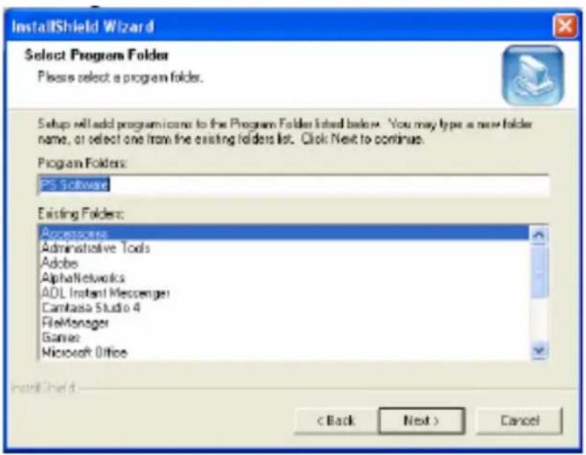
- The InstallShield Wizard starts to install the software, and the Progress bar indicates the installation is proceeding until the following window shows up. Click the Finish button to complete the installation.

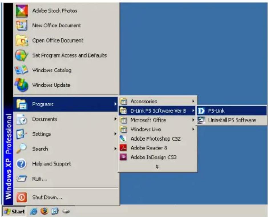
After installing the program, you can access the utilities by clicking Start→ Programs→ PS Software → PS Link.
Using PS-Link
PS-Link (Windows 2000/XP/2003/Vista), is a utility that will help you use your printer manufacturer drivers with the MFP print server. Using the Link command you can simulate a physical USB connection between your computer and printer, thus enabling you to complete the installation of the manufacturer drivers without making a USB connection to your computer.
To start PS-Link, go to Start→ Programs→ PS Software, and click PS-Link.
PS-Link will then start and automatically search for MFP servers in the same network segment. If the installation has been successful, you will see that the name of your MFP server has been discovered and is listed in the Server Name column. If your MFP server is not listed, please check your network connectivity and click the Discover button again.


Server Name: This list displays the name of the MFP Servers within the network.
Discover: Click this button to search for more MFP Servers.

Status Bar: The status bar at the bottom of the screen displays the current system status and number of connected MFP servers.

Information: This field displays basic information regarding the selected MFP Server in the Device List.
There are also two buttons: Change IP Address, and Web Setup. Here is an explanation of each button:
Using PS Software
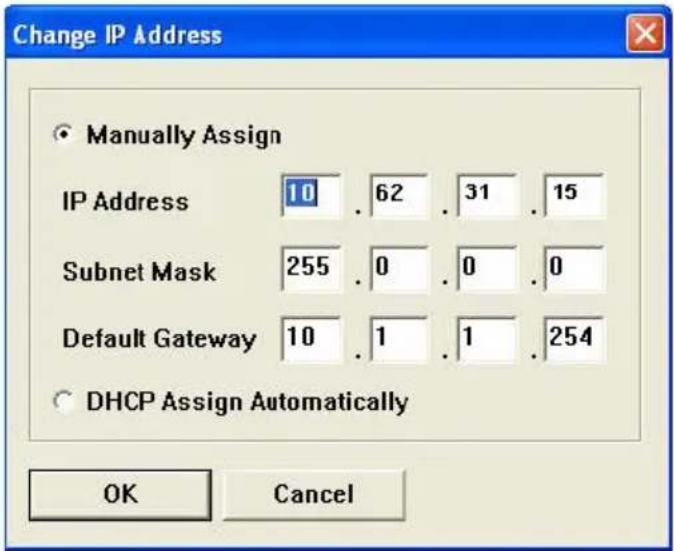
[Change IP Address] - Click this button to bring up the following screen. This screen allows you to change the IP Address of the MFP Server. Select Manually Assign to enter a specific IP address for the MFP server or DHCP Assign Automatically to assign the server an IP address automatically. Click OK to save your changes or Cancel to abort.
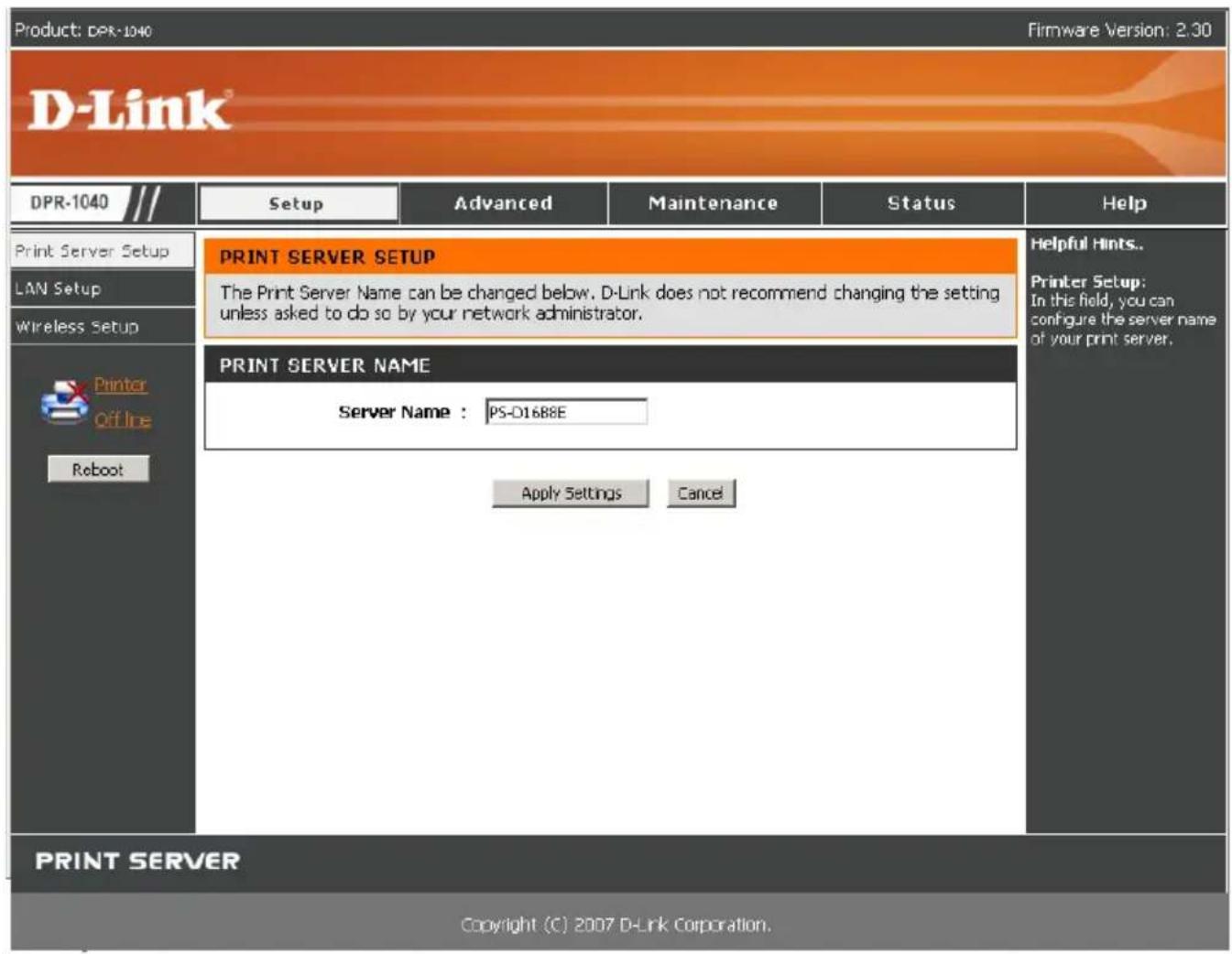
[Web Setup] – Click this button to launch the web configurator. You can also launch the web configurator by clicking on the name of the server in the Device List.

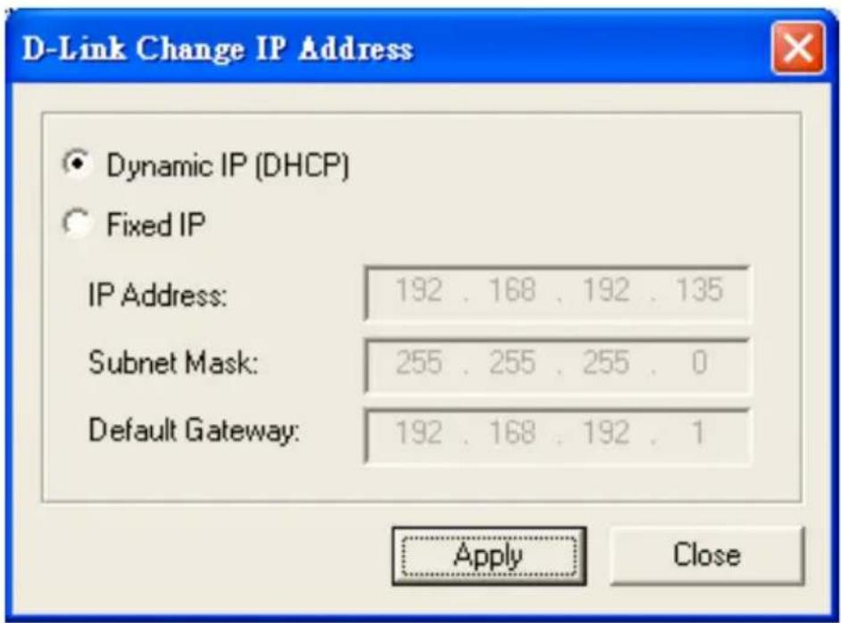
Printer Port: This field displays basic information and the current status of the connected printer. It also allows you to use Link and UnLink.
[Link] – The function of this button is to simulate the physical connection between the printer and computer via a USB cable. This means you can set up a link by simply clicking this button without physically attaching the printer's USB cable to your computer. This is because the USB cable will be connected from your printer to the print server and not to your computer.
[UnLink] – This button disconnects the simulated link between the printer and the computer.

About: Click this to display the PS-Link version number. Click the OK button to close this window.

Close: To exit PS-Link, click this button.
Installing and Using MFP/GDI Printers
This section will tell you how to install a MFP/GDI printer through the PS-Link utility. This is helpful when you do not have physical access to the printer.
For PCs with the MFP/GDI printer driver installed:
If your computer already has the MFP/ GDI printer driver installed, you can just click the [Link] button in PS-Link to complete the connection between the printer and your computer.
For PCs without the MFP/GDI printer driver installed:
If your computer does not have the MFP/GDI printer driver installed, you may use the following procedure:
- Insert the DPR-1040 installation CD into your computer's CD-ROM drive to install the PS-Link software.
- Insert the manufacturer's CD-ROM into your computer's CD-ROM drive to initiate the auto-run program.
- Following the instructions on the manufacturer's installation CD to install the MFP driver and other software until you are requested to attach the printer's USB cable to your computer. At this stage you must use the PS Link utility to simulate the connection and complete the installation.
- The installation steps may be different depending on the printer and manufacturer brand. Below you will find diagrams for several printers from different manufacturers.
For HP:

flowchart
graph TD
    A["Install MFP/GDI Printer CD-ROM"] --> B["Request: Connect the printer to your PC"]
    B --> C["Continue the installation"]
    C --> D["Installation is finished"]
    D --> E["PS-Link Utility"]
    E --> F["Start to use the MFP/GDI printer on your PC"]
    B --> G["1. Check the box and ✓ If you are unable to connect your device now, click this box and then click Next to finish installing the software. You can connect your device later."]
    E --> H["2. Click Next> button to continue"]
- When the installation program asks you to connect the USB cable you are allowed to connect it later by checking a box. Click the Next > button to continue the rest of the installation.
- When the installation of all drivers has been completed, you may use the PS-Link
Using PS Software
utility to complete the physical connection between the MFP/GDI printer and your computer by clicking the [Link] button.

If the connection has been made successfully, the following message will display. Press OK to exit.
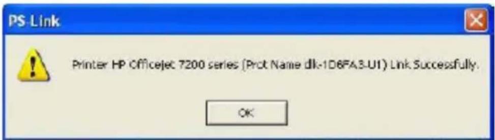
- Now the MFP/GDI printer is ready to use. You may start to use the MFP/GDI printer through your computer.
For EPSON:

flowchart
graph TD
    A["Install MFP/GDI Printer CD-ROM"] --> B["Request: Connect the printer to your PC"]
    B --> C["PS-Link Utility"]
    C --> D["Continue the installation"]
    D --> E["Installation is finished"]
    E --> F["Start to use the MFP/GDI printer on your PC"]
    G["Click [Link"] button to connect the printer and your PC] --> C
- When the installation program asks you to connect the USB cable of the MFP/GDI printer to your computer, you are not allowed to ignore it; therefore, you need to use PS-Link to simulate a USB connection between your printer and computer.

- Launch the PS-Link utility and click the [Link] button.
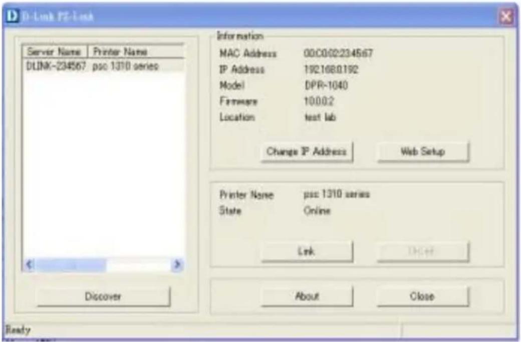
When the connection has been completed successfully, a message will display. Press OK to exit.
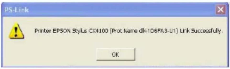
-
Now you have to go back to continue the installation of the MFP/GDI printer CD-ROM on your computer in order to complete the rest of installation steps.
-
When the installation is complete, you can start to use the Print, Scan, Copy and Fax functions of the MFP/GDI printer through your computer.
For Canon:

flowchart
graph TD
    A["Install MFP/GDI Printer CD-ROM"] --> B["Request: Connect the printer to your PC"]
    B --> C["PS-Link Utility"]
    C --> D["Continue the installation"]
    D --> E["Installation is finished"]
    E --> F["Start to use the MFP/GDI printer on your PC"]
    C --> G["Click [Link"] button to connect the printer and your PC]
- When the installation program asks you to connect the USB cable of the MFP/GDI printer to your computer, you are not allowed to ignore it; therefore, you need to use PS-Link to simulate a USB connection between your printer and computer.

- Launch the PS-Link utility and click the [Link] button.

Using PS Software
When the connection has been completed successfully, a message will display. Press OK to exit.

-
Now you have to go back to continue the installation of the MFP/GDI printer CD-ROM on your computer in order to complete the rest of installation steps.
-
When the installation is complete, you can start to use the Print, Scan, Copy and Fax functions of the MFP/GDI printer through your computer.
For Lexmark:

flowchart
graph TD
    A["Install MFP/GDI Printer CD-ROM"] --> B["Request: Connect the printer to your PC"]
    B --> C["PS-Link Utility"]
    C --> D["Continue the installation"]
    D --> E["Installation is finished"]
    E --> F["Start to use the MFP/GDI printer on your PC"]
    G["Click [Link"] button to connect the printer and your PC] --> C
- When the installation program asks you to connect the USB cable of the MFP/GDI printer to your computer, you are not allowed to ignore it; therefore, you need to use PS-Link to simulate a USB connection between your printer and computer.

- Launch the PS-Link utility and click the [Link] button.

When the connection is completed successfully, a message will display. Press OK to exit.

-
Now you have to go back to continue the installation of the MFP/GDI printer CD on your computer in order to complete the rest of installation steps.
-
When the installation is complete, you can start to use the Print, Scan, Copy and Fax functions of the MFP/GDI printer through your computer.
For Samsung:

flowchart
graph TD
    A["Install MFP/GDI Printer CD-ROM"] --> B["Request: Connect the printer to your PC"]
    B --> C["Continue the installation"]
    C --> D["Installation is finished"]
    D --> E["PS-Link Utility"]
    E --> F["Start to use the MFP/GDI printer on your PC"]
    B -->|Ignore it and click Next> button to continue| G
    E -->|Click["Link"] button to connect the printer and your PC| H
- When the installation program asks you to connect the printer to your computer, just ignore it and click the Next> button to continue.
![Samsung SCX 4200 Series Connect Device Setup can not find a connected device. Check connection between your computer and the printer SAMSUNG If you want to install Samsung SCX-4200 Series properly you have to connect Samsung SCX-4200 Series before installation. You may connect the device using the printer cable as the figure shows, then turn on the power of Samsung SCX-4200 Series. Click [Next] Please refer to the following connection method. 1. Connect the device to your computer 2. Turn on the power of the device 3. If "New Hardware Wizard" is appeared, close it. 4. Click [Next] Cancel](/content/2026/06/1397830/images/245f9e892958d2dd0cad47e9f9fabf3d27a4108702fcf213fc98d0c5b1a1fe98.jpg)
Using PS Software
- The program will prompt you again to connect the two devices, click No and continue with the rest of the installation.
![Samsung SCX-4200 Series Device is not connected or power is turned off Connect the device and turn on the power, then click [YES] button. If you want to install without connected device then click [NO] button. Yes No](/content/2026/06/1397830/images/87de80bc92b66d315a3d3f9280322902c6fff84bae3918d80c1fe00fb168c566.jpg)
- After the installation of the MFP/GDI printer CD has finished, you may use
PS-Link to complete the physical connection between the MFP/GDI printer and your computer.
Click the [Link] button of the PS-Link window as below.

When the connection is successful, a message will display. Press OK to exit.

- Now the MFP/GDI printer is ready to use through your computer.
For Brother:

flowchart
graph TD
    A["Install MFP/GDI Printer CD-ROM"] --> B["Request: Connect the printer to your PC"]
    B --> C["PS-Link Utility"]
    C --> D["Continue the installation"]
    D --> E["Installation is finished"]
    E --> F["Start to use the MFP/GDI printer on your PC"]
    G["Click [Link"] button to connect the printer and your PC] --> C
- When the installation program asks you to connect the USB cable of the MFP/GDI printer to your computer, you are not allowed to ignore it; therefore, you need to use PS-Link to simulate a USB connection between your printer and computer.

- Launch the PS-Link utility and click the [Link] button.

Using PS Software
When the connection has been completed successfully, a message will display to inform you. Press OK to exit.

- Now you have to go back to continue the installation of the MFP/GDI printer CD on your computer in order to complete the rest of installation steps.
- When the installation is complete, you can start to use the Print, Scan, Copy and Fax functions of the MFP/GDI printer through your computer.
For Fuji Xerox:

flowchart
graph TD
    A["Install MFP/GDI Printer CD-ROM"] --> B["Installation is finished"]
    B --> C["PS-Link Utility"]
    C --> D["Start to use the MFP/GDI printer on your PC"]
    C --> E["Click [Link"] button to connect the printer and your PC]
-
The installation program of the Xerox MFP/GDI printer will not request you to make a physical connection between the printer and your computer.
-
After the installation has finished, you will have to link the connection between the MFP/GDI printer and your computer in order to use the printer on your computer. To do this you need to use PS-Link to link the two devices.
Launch the PS-Link utility and click the [Link] button.

When the connection has been completed successfully, a message will display to inform you. Press OK to exit.
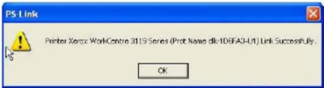
- Now the MFP/GDI printer is ready to use through your computer.
Using the Web Configurator
HOME
To begin managing the DPR-1040, launch your browser and go to the following URL address:
dlink-xxxxxx
xxxxxx being the last six digits of the DPR-1040's MAC address. The MAC address can be found on the bottom of the DPR-1040.
You can also access the web configurator by typing the IP address of the device. The default IP address is 192.168.0.10 but this may have changed if you have a DHCP server on your network.
When you enter the correct URL, a password input dialog will pop up. Input “admin” in the User name field, leave the Password field as blank, and click the OK button to login.

This is the main screen of the Print Server's web configurator. In addition to product information, there are five links on the top of the main screen: Setup, Advanced, Maintenance, Status, and Help. Clicking a link from the bar will display its submenu, selecting an option from the submenu will display the content in the center of the screen.

SETUP > Print Server Setup
The Print Server Setup screen allows you to modify the Print Server Name and Port Name. D-Link does not recommend changing these settings unless asked to do so by your network administrator.

Print Server Name
In this section, you can configure the basic information of MFP server. The basic information contains a name of the print server, assigned in the Server Name field, and a location for the print server, assigned in Location (optional) field.
Using the Web Configurator
Port Settings
In this section you can assign the Port Name for the print server and the description for the USB printer port.
Click the Apply Settings button to save any changes or click Cancel to exit.
SETUP > LAN Setup
The LAN Setup screen allows you configure the print server's local network settings. Please note that this section is optional and you should not need to change any of the settings here to get the print server up and running.

TCP/IP
These fields allow you to assign an IP address automatically or manually. When clicking Manually Assign, you should enter the following information in the boxes:
IP Address, Subnet Mask, and Default Gateway.
If you have made changes click Apply Settings to save them or click Cancel to exit.
SETUP > Wireless Setup
Use this screen to set up your wireless connection. You can change the wireless connection details and also apply/remove wireless security such as WEP or WPA.

Wireless Interface
[Connection Mode] Select the type of wireless network you are connecting to.
Select Infrastructure if you are connecting to a wireless router or access point.
Select Ad-Hoc to connect directly to a computer with an Ad-Hoc network set up.
[SSID] Type the name of the network the Print Server is connecting to. Click the Site
Using the Web Configurator
Survey button to see the names of the wireless networks already in-range.
[Wireless Channel] Select the channel that the wireless network you are connecting to is using.
Encryption
[Wireless Security] Select the type of wireless security the network you are connecting to is using. This may be WEP, WPA or WPA2-PSK.
Click Apply Settings to save your changes. Click Cancel to exit without saving any changes.
SETUP > Printer Setup
The Printer Setup screen allows you to install the printer drivers for the printer currently connected to your print server.
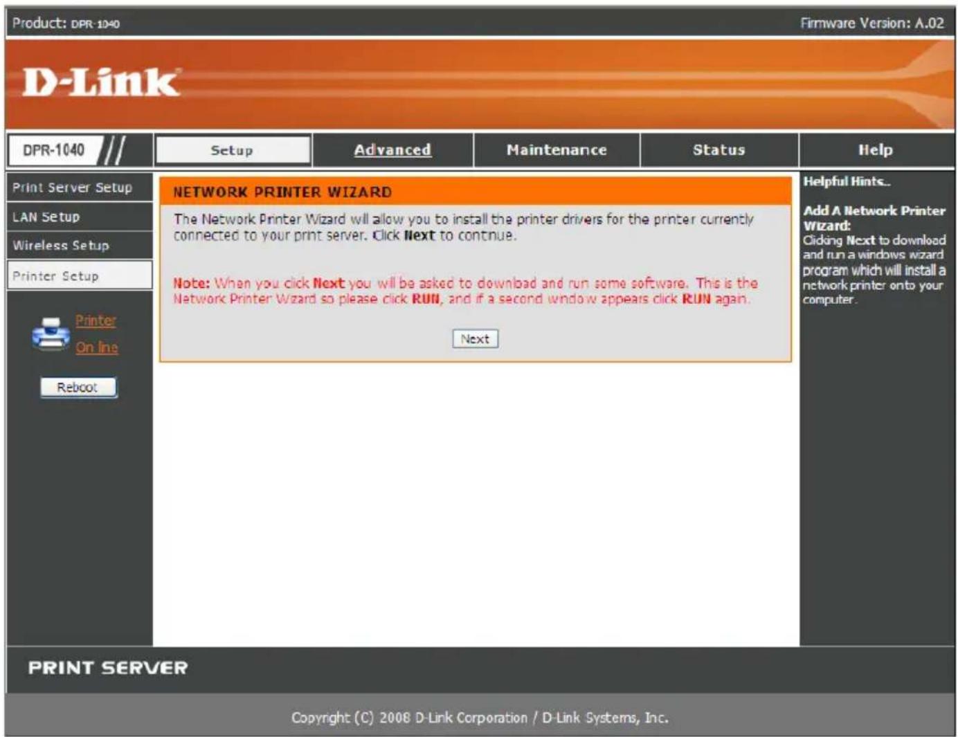
Network Printer Wizard
Click Next to download a windows wizard program which will install a network printer onto your computer.
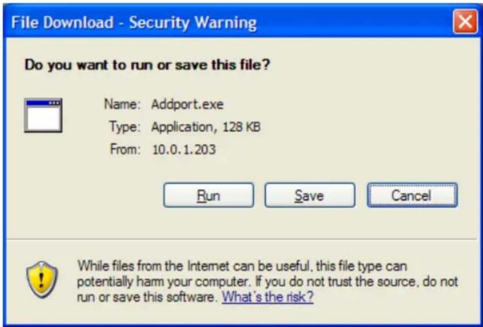
Click RUN to download and run the wizard. If a security warning appears click RUN again.


- Select the correct Windows printer from the list, and click the Connect button. If the correct printer type is not listed, install the drivers and run the wizard again.
Using the Web Configurator

If prompted about sharing the printer, do not enable it.
- Installation is now complete. You can now print using this printer.
ADVANCED > Advanced LAN
The Advanced LAN screen allows you to change more advanced network settings for the MFP server. It's recommended not to change these settings unless instructed to do so by your network administrator.
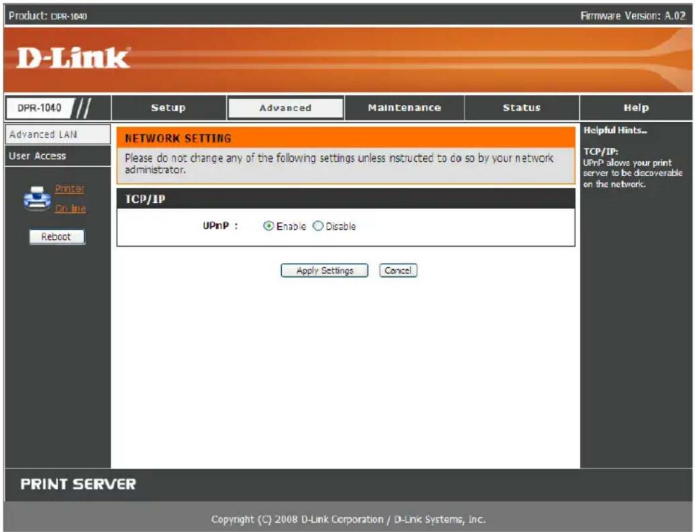
TCP/IP
UPnP: This option allows you to enable or disable UPnP.
ADVANCED > User Access
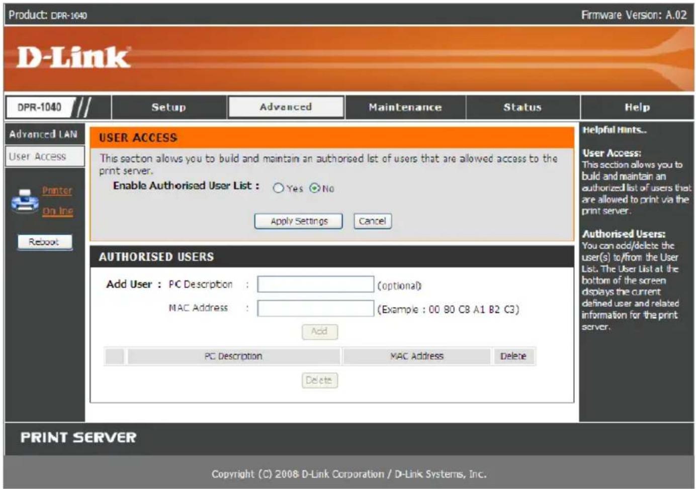
The User Access screen allows you to create and maintain an authorized list of users that are allowed to access the MFP server.

User Access
By enabling the Enable Authorised User List option (Yes), the users in the User List below will be permitted to access the print server. Any user who is not added to this list will not be allowed to access the print server. Once you have changed the settings, click the Apply Settings button to store the settings or click Cancel to exit.
Authorised Users
You can add or delete any user to or from the User List. The User List at the bottom
of the screen displays the currently defined users and their related information.
MAINTENANCE > Password
The Password screen allows you to change the password of the MFP server by entering the current password in the Current Password field and your new password in the New Password and Confirm Password fields. Click the Apply Settings button to save the new password, or click Cancel to exit without saving.
NOTE: The default password for the MFP server is blank.

MAINTENANCE > Save/Restore Settings
The Save/Restore Settings screen allows you to save the current device configuration in a computer for later backup. It also allows you to reload a previous configuration.
To save the current device configuration click the [Save] button. To reload a previous configuration click [Browse] and select the backup file, then click [Update Settings] to reload it. You can also return the device to factory default settings by clicking [Restore Device].

MAINTENANCE > Firmware Upgrade
The Firmware Upgrade screen displays the current firmware information of the MFP server. It also allows you to upgrade the firmware of the MFP server when a new version of firmware is available.
Click Browse to point to the firmware file on your computer, and then click Upgrade.

MAINTENANCE > Diagnostics
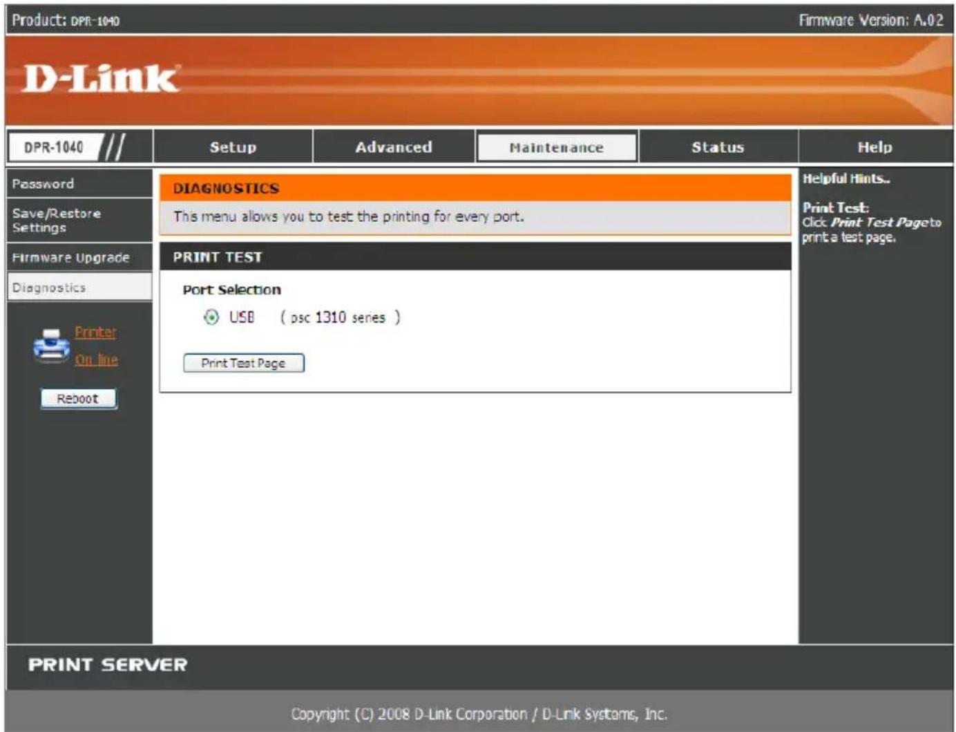
The Diagnostics screen allows you to test the printing for each printer connected via USB to the device. After making the port selection, click the Print Test Page button to print a test page.
STATUS > Device Info
The Device Info screen displays the status of your MFP Server, printer, and network for your reference.

Print Server Status
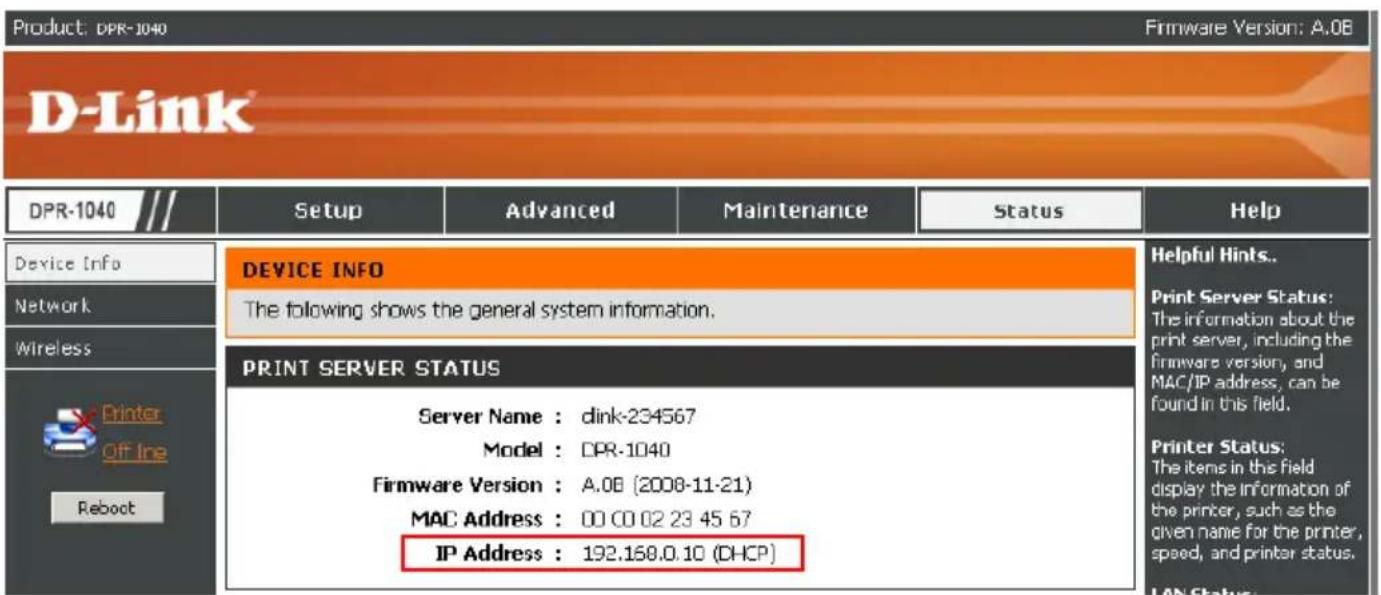
The fields in this section display the server name, firmware version of the device and MAC/IP address.
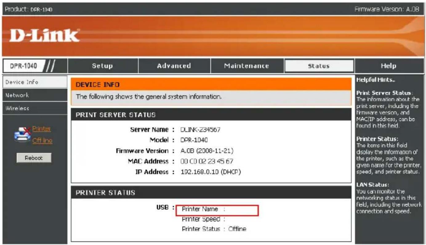
Printer Status
The items in this section display information regarding the printer connected to the
Using the Web Configurator
USB port such as name, speed, and printer status.
LAN Status
You can monitor the networking status in this field, including the network connection status and speed.
STATUS > Network
The Network screen displays the general network status of your print server, including:
Auto IP
This section displays the current settings of DHCP/BOOTP and UPnP.
The items in this screen are configured in Advanced > Advanced LAN.

STATUS > Wireless
This screen displays information about the current wireless connection.
You can monitor the connection mode (Infrastructure or Ad-Hoc), link status, SSID, channel, and data encryption status.

HELP
The Help screen provides you with additional support information regarding the MFP server.

Reboot
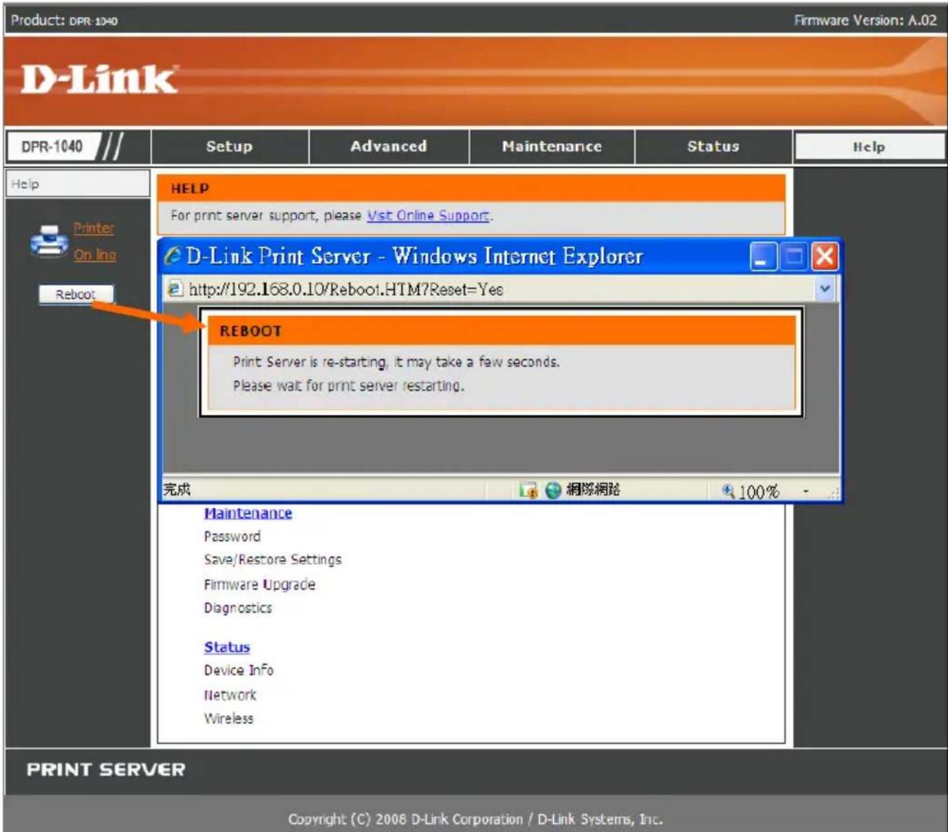
If you want to reset the MFP server, click the Reboot button. A screen will display informing you the printer is restarting.
Refresh Printer Status
Click the printer in the left column to refresh the status of the printer.

TCP/IP Printing for Windows Vista
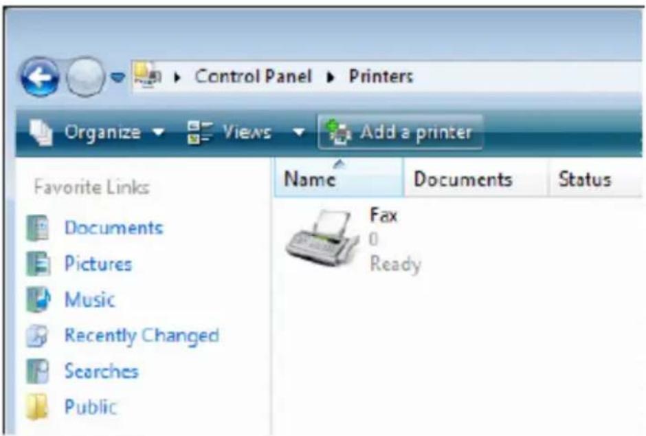
Go to Start > Control Panel > Printers.

Click Add a printer.
Select the first option, Add a local printer, and then click Next.

Select the second option, Create a new port, and highlight Standard TCP/IP Port from the pull-down menu. Click Next.

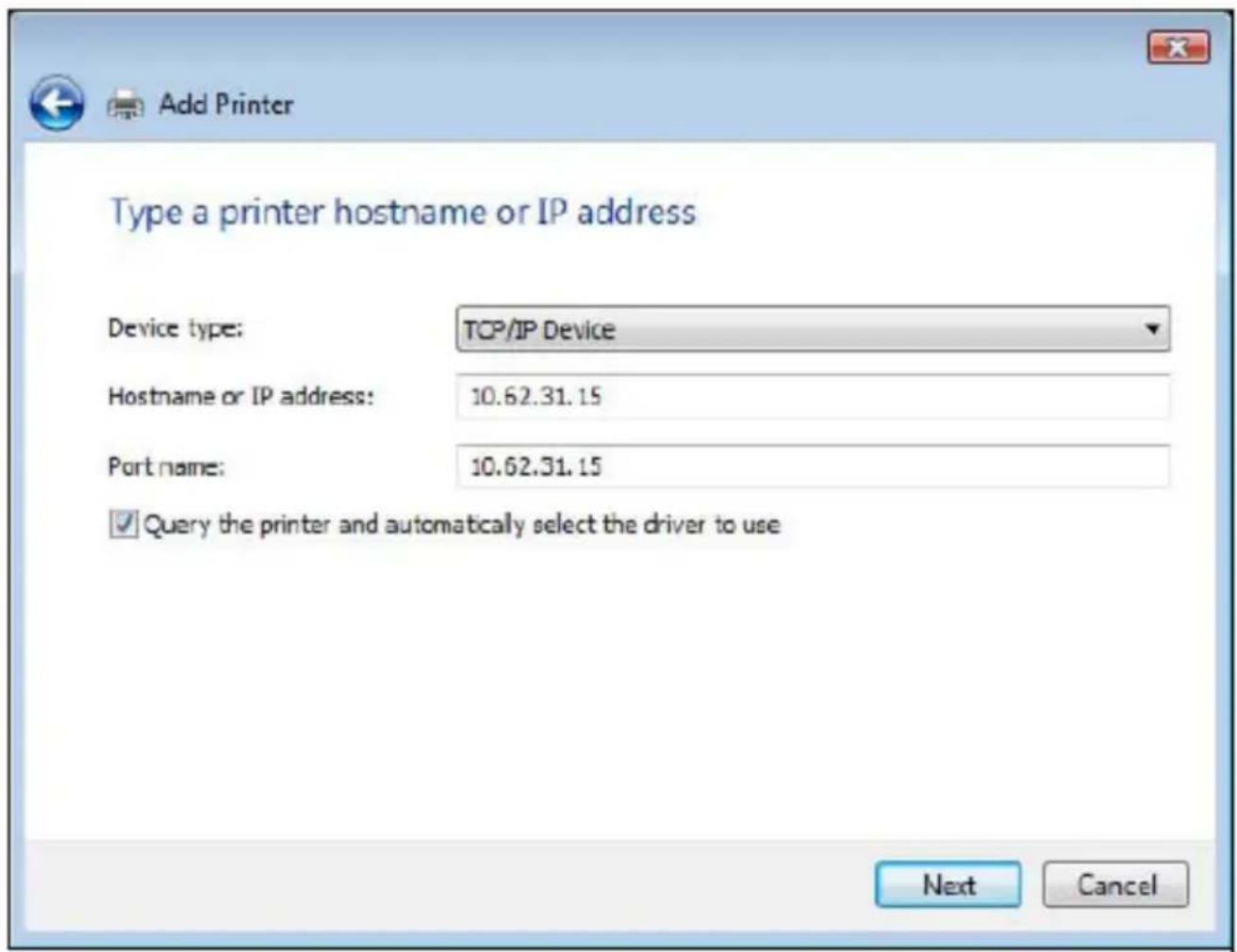
In the Hostname or IP address field, type the IP address of the MFP server (e.g. 10.62.31.15), this address can be found in the PRINTER SERVER STATUS screen of the MFP server's web configurator. The Port Name field will automatically fill in. Click Next.
In the next screen highlight the printer you wish to add. If the printer is not on the list,
click [Have Disk] and insert the printer driver disk that came with your printer to install the printer drivers.
Click Next.

Click Next to start installing the printer.

After clicking Print a test page, a small dialogue box will display as below. Click Close.

Click Finish.

The printer is now ready to use.
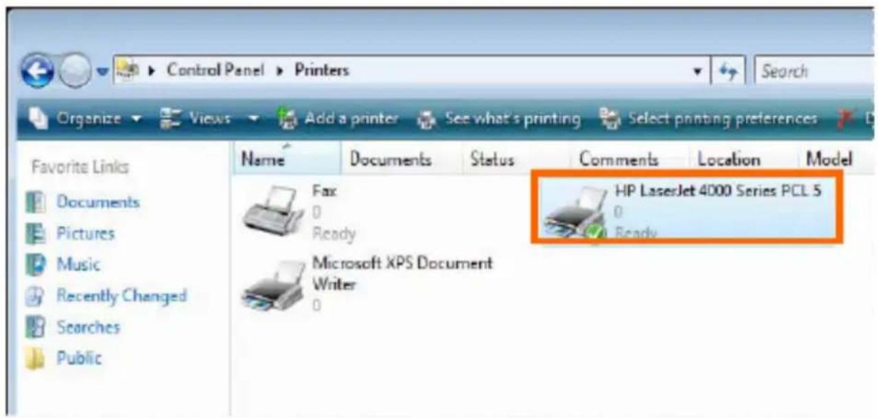
TCP/IP Printing for Windows XP
Go to Start > Printers and Faxes > Add a Printer.
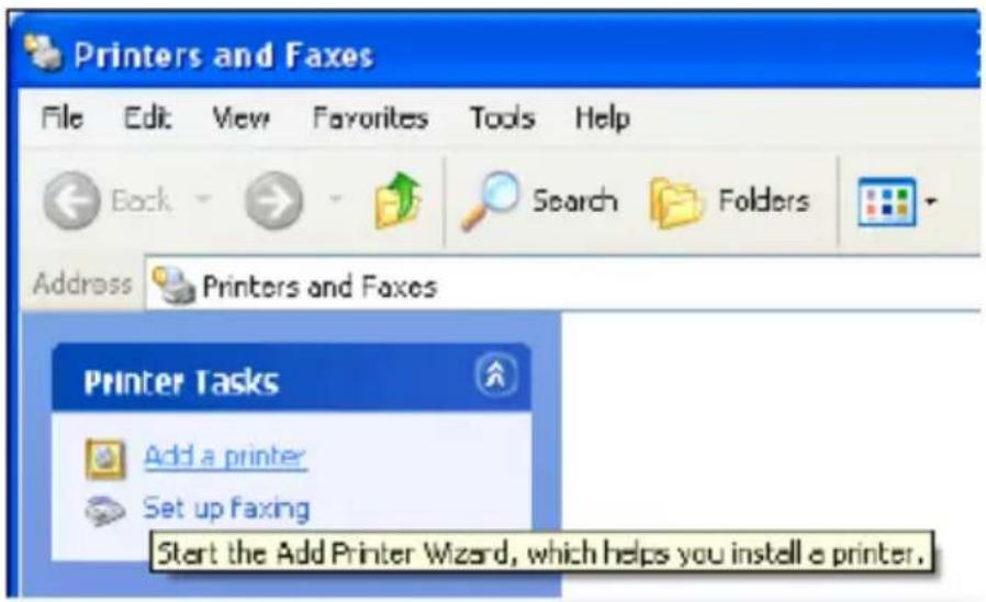
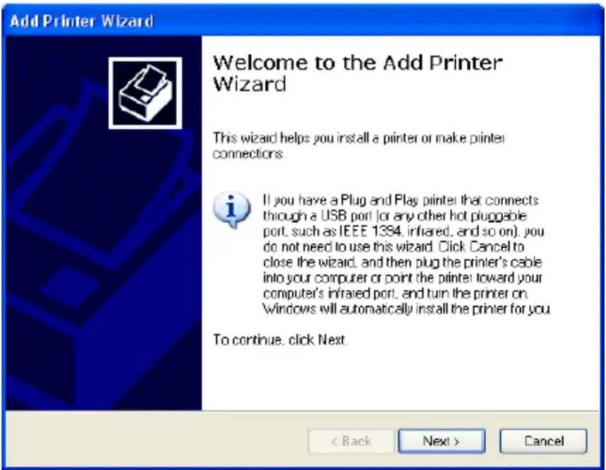
When the following screen displays, click Next.
Select the first option, Local printer attached to this computer, and click Next.

Click the second option, Create a new port, and select Standard TCP/IP Port from the drop-down list box. Click Next.
![Add Printer Wizard Select a Printer Port Computers communicate with printers through ports. Select the port you want your printer to use. If the port is not listed, you can create a new port. Use the following port: LPT1: [Recommended Printer Port] Note: Most computers use the LPT1 port to communicate with a local printer. The connector for this port should look something like this. Create a new port: Type of port: Standard TCP/IP Port < Back Next > Cancel](/content/2026/06/1397830/images/20d3ce067b1d5bda54cb471d0bea09b15ed823b8f2596bdec9491e0ff50bfbf1.jpg)
Click Next.
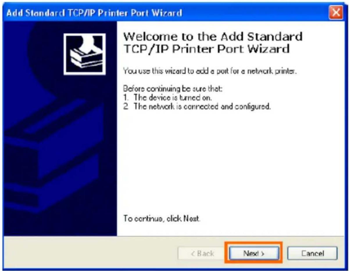
In the Hostname or IP address field, type the IP address of the MFP server (e.g. 10.62.31.15), this address can be found in the PRINTER SERVER STATUS screen of the MFP server's web configurator. The Port Name field will automatically fill in. Click Next.

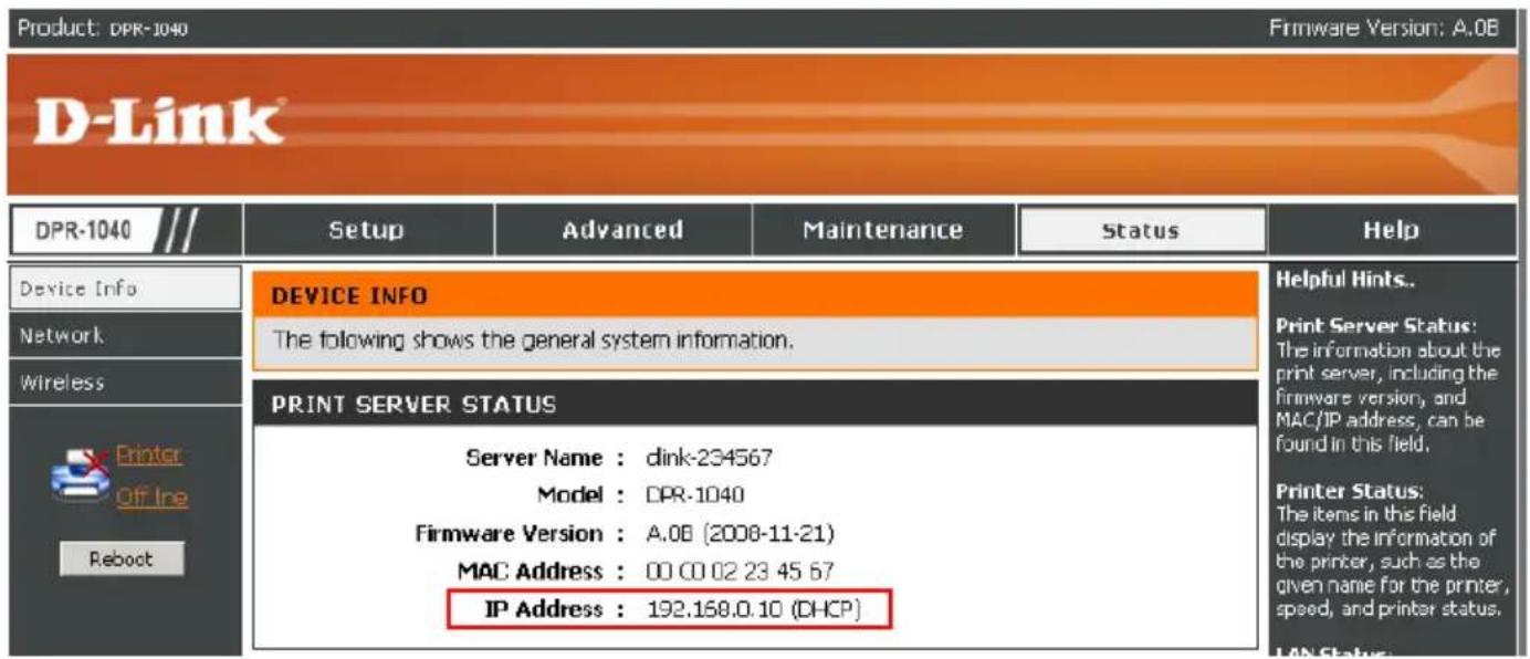
Select Custom and click Settings.

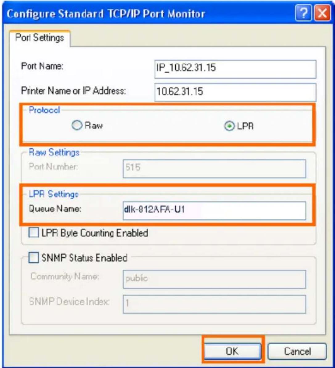
The following screen will display, select LPR from the Protocol field.
Enter the Queue Name, which can be found in the PRINTER STATUS screen of the MFP server's web configurator. Click OK.
Click Next.

Click Finish.

In the next screen highlight the printer you wish to add. If the printer is not on the list, click [Have Disk] and insert the printer driver disk that came with your printer to install the printer drivers.
Click Next.

At this screen, you can input a name for the printer, and then click Next.

Select Yes to print a test page, click Next.

Click Finish. The printer is now ready for use.
Add Printer Wizard

Completing the Add Printer Wizard
You have successfully completed the Add Printer Wizard. You specified the following printer settings:
Name: HP LaserJet 4000 Series PCL
Share name:
Poit: IP_10.62.31.15
Model: HP LaserJet 4000 Series PCL
Default: Yes
Test page: Yes:
To close this wizard, click Finish.
< Back
Finish
Cancel
TCP/IP Printing for Windows 2000
Go to Start > Settings > Printers and Faxes > Add a Printer.

When the following screen shows up, click Next.

Select the first option, Local printer, and click Next.
Add Printer Wizard
Local or Network Printer
Is the printer attached to your computer?

If the printer is directly attached to your computer, click Local printer. If it is attached to another computer, or directly to the network, click Network printer.
Local printer
□ Automatically detect and install my Plug and Play printer
C Network printer
< Back
Next>
Cancel
Click Next if the New Printer Detection screen pops up.
On the next screen, select the second option Create a new port and highlight Standard TCP/IP Port from the drop-down list. Click Next.
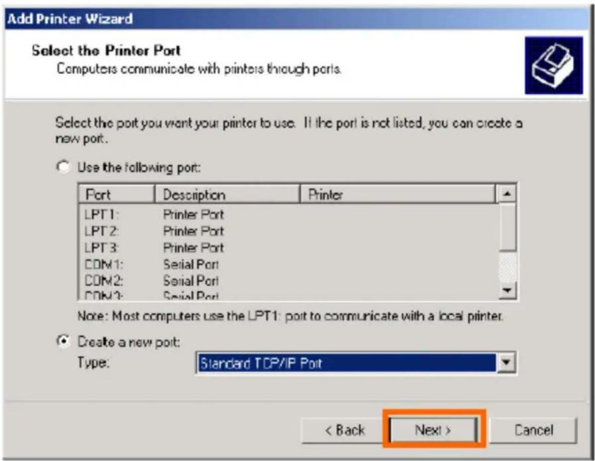
Click Next.

In the Hostname or IP address field, type the IP address of the MFP server (e.g. 10.62.31.15), this address can be found in the PRINTER SERVER STATUS screen of the MFP server's web configurator. The Port Name field will automatically fill in. Click Next.
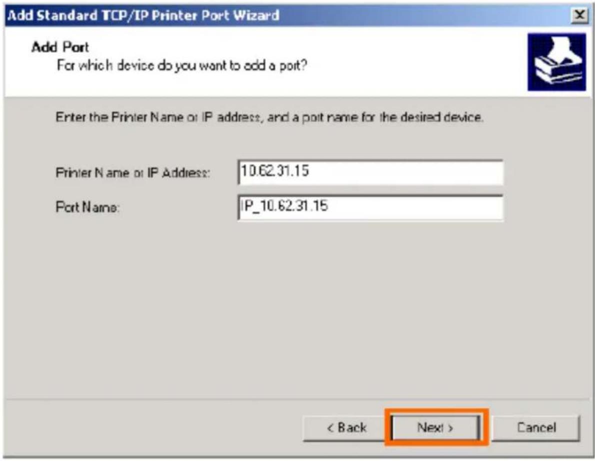

Select Custom and click Settings.
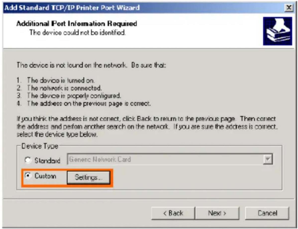
The following screen will display, select LPR from the Protocol field.
Enter the Queue Name, which can be found in the PRINTER STATUS screen of the MFP server's web configurator. Click OK.


Click Finish.
In the next screen highlight the printer you wish to add. If the printer is not on the list, click [Have Disk] and insert the printer driver disk that came with your printer to install the printer drivers.
Click Next.
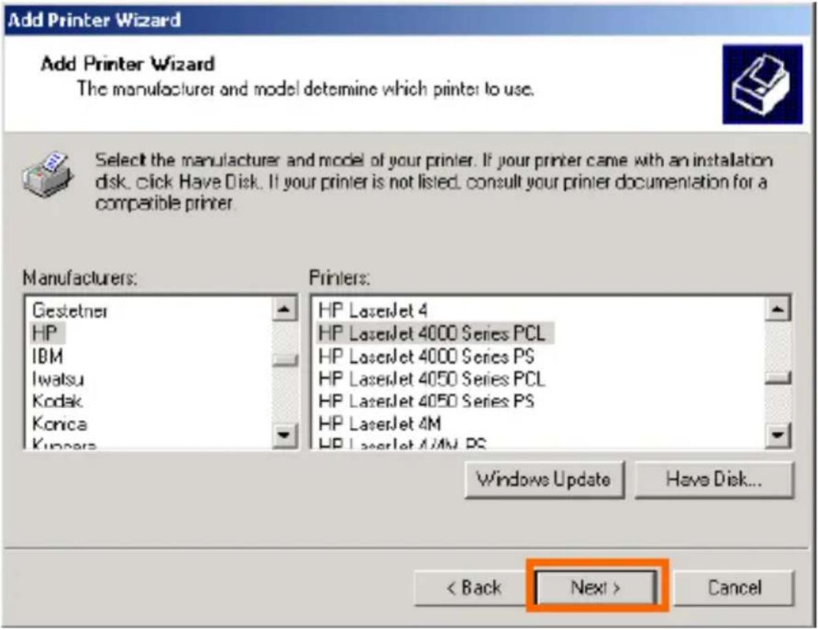
At this screen, input a name for the printer, and then click Next >.

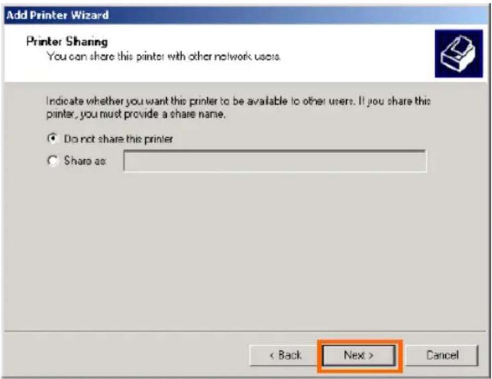
Select the first option, Do not share this printer, and click Next.
Select Yes to print a test page, click Next.
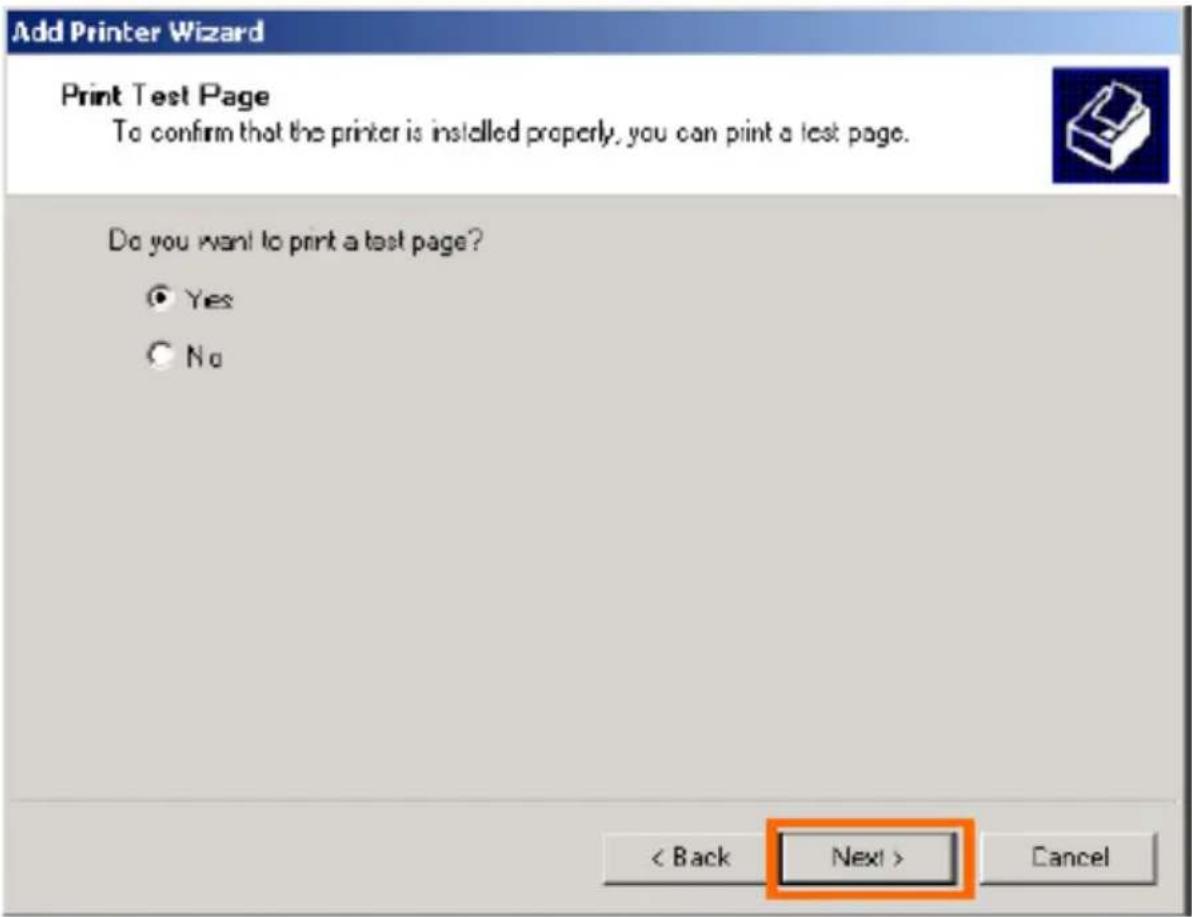
Click Finish. The printer is now ready for printing with Windows 2000 on your network.
Add Printer Wizard

Completing the Add Printer Wizard
You have successfully completed the Add Printer wizard.
You specified the following printer settings:
Name: HP LaserJet 4000 Series PCL
Shared as:
Port: IP_10.62.31.15
Model: HP LaserJet 4000 Series PCL
Default: Yes
Test page: Yes
To close this wizard, click Finish.
< Back
Finish
Cancel
Setting up Printing in Mac OS X Tiger (10.4.9)
NOTE: Mac OS printing is supported by Postscript printers only!
With Mac OS X Tiger (10.4), you can use Line Printer Daemon (LPD) printing through the Print Server.
Adding a Printer
Use the Go menu at the top tool bar and select Applications option and find the Utilities folder or open the Utilities folder directly in Go menu.
![Go Window Help Back ⌘[ Forward ⌘] Enclosing Folder ⌘↑ Computer ⌘C Home ⌘H Network ⌘K iDisk ► Applications ⌘A Utilities ⌘U Recent Folders ► Go to Folder... ⌘G Connect to Server... ⌘K](/content/2026/06/1397830/images/17ce9814d32e56ba09ee2ad4412c6c26d539e592ee34a7c2aaa0b660c47f8a64.jpg)
In the Utilities folder, find and select List dialog window.
Printer Setup Utility
to see the Printer

Click Add button to open Printer Browser window.

Mac OS X Tiger (10.4) supports one printing protocol:
- Line Printer Daemon (LPD)
To set up LPD Printing
- Enter the IP address of the print server to which the printer is attached in Address field.
- Type the port name in the Queue field.
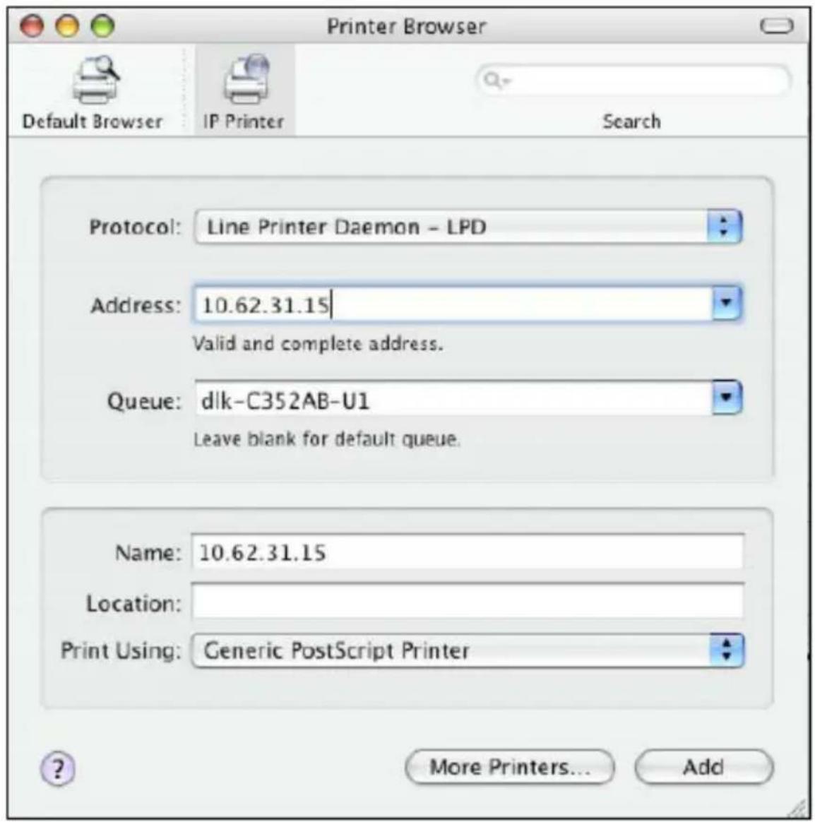
Click the Add button after selecting the printer model in the Print Using drop-down menu.
Set up Socket Printing
- Enter the IP address of the print server to which the printer is attached in Address field. After that, type “: 9100” for port 1.
- Keep the Queue field blank.

Click the Add button after selecting the printer model in the Print Using drop-down menu.
When the Installable Options screen is displayed as below, click the Continue button.

The printer that has just been added will show up in the Printer List menu, it might take a few seconds depending on network conditions. When the printer appears listed it is ready for use. Quit the Printer Setup Utility and start printing.

Technical Specifications
Printer Connection
Printer Port: USB 2.0
Bi-directional Communication: Hewlett-Packard PJL (Printer Job Language)
standard for bi-directional communication.
Network Connection
Network Standards: 100Base-TX Fast Ethernet, 802.11b/g Wireless Standard
Network Data Transfer Rate: 10/100 Mbps (megabits per second), Up to 54Mbps
Network Interfaces: RJ-45, 802.11b/g wireless LAN
Wireless Security: 64/128 bit WEP, WPA/WPA2, WPS support
Network Protocols
Ethernet Frame Types: 802.2, 802.3, Ethernet II, SNAP (auto-switching)
Transport Protocols: TCP/IP, LPR, RAW, IPP
TCP/IP Protocols Supported: BOOTP, LPD, RARP, DHCP, IPP
Management and Diagnostics
Diagnostic LED Indicators: Power, USB, LAN, Wireless
Environmental and Physical
Power Supply: External power supply providing 5V, 1.2A DC
Dimensions: 67(W) x 25(H) x 106(D)mm
Weight: approx. 2.88 oz. (82g)
Operating Temperature: 32 to 104 °F (0 to 40°C)
Storage Temperature: -13 to 131°F (-25 to 55 °C)
Humidity: 5% to 95% non-condensing
Emissions: FCC Class B, CA IC RF, CE Class B, UL/c-UL, AU A-Tick, NCC
Contacting Technical Support
Technical Support
You can find software updates and user documentation on the D-Link website.
D-Link provides free technical support for customers within the United States and within Canada for the duration of the warranty period on this product.
U.S. and Canadian customers can contact D-Link technical support through our website, or by phone.
Tech Support for customers within the United States:
D-Link Technical Support over the Telephone:
(877)453-5465
24 hours a day, seven days a week.
D-Link Technical Support over the Internet:
http://support.dlink.com
email:support@dlink.com
Tech Support for customers within Canada:
D-Link Technical Support over the Telephone:
(800)361-5265
Monday to Friday 8:30am to 9:00pm EST
D-Link Technical Support over the Internet:
http://support.dlink.ca
email:support@dlink.ca
When contacting technical support, please provide the following information:
- Serial number of the unit
• Model number or product name - Software type and version number
Warranty and Registration
Subject to the terms and conditions set forth herein, D-Link Systems, Inc. (—D-Link") provides this Limited warranty for its product only to the person or entity that originally purchased the product from:
D-Link or its authorized reseller or distributor and
Products purchased and delivered within the fifty states of the United States, the District of
Columbia, U.S. Possessions or Protectorates, U.S. Military Installations, addresses with an APO or FPO.
Limited Warranty: D-Link warrants that the hardware portion of the D-Link products described below will be free from material defects in workmanship and materials from the date of original retail purchase of the product, for the period set forth below applicable to the product type (—Warranty Period“), except as otherwise stated herein.
1-Year Limited Warranty for the Product(s) is defined as follows:
Hardware (excluding power supplies and fans) One (1) Year
Power Supplies and Fans One (1) Year
☐ Spare parts and spare kits ninety (90) days.
D-Link's sole obligation shall be to repair or replace the defective Hardware during the Warranty Period at no charge to the original owner or to refund at D-Link's sole discretion. Such repair or replacement will be rendered by D-Link at an Authorized D-Link Service Office. The replacement Hardware need not be new or have an identical make, model or part. D-Link may in its sole discretion replace the defective Hardware (or any part thereof) with any reconditioned product that D-Link reasonably determines is substantially equivalent (or superior) in all material respects to the defective Hardware. Repaired or replacement Hardware will be warranted for the remainder of the original Warranty Period from the date of original retail purchase. If a material defect is incapable of correction, or if D-Link determines in its sole discretion that it is not practical to repair or replace the defective Hardware, the price paid by the original purchaser for the defective Hardware will be refunded by D-Link upon return to D-Link of the defective Hardware. All Hardware (or part thereof) that is replaced by D-Link, or for which the purchase price is refunded, shall
Warranty and Registration
become the property of D-Link upon replacement or refund.
Limited Software Warranty: D-Link warrants that the software portion of the product (—Software") will substantially conform to D-Link's then current functional specifications for the Software, as set forth in the applicable documentation, from the date of original retail purchase of the Software for a period of ninety (90)days (—Warranty Period"), provided that the Software is properly installed on approved hardware and operated as contemplated in its documentation. D-Link further warrants that, during the Warranty Period, the magnetic media on which D-Link delivers the Software will be free of physical defects. D-Link's sole obligation shall be to replace the non-conforming Software (or defective media) with software that substantially conforms to D-Link's functional specifications for the Software or to refund at D-Link's sole discretion. Except as otherwise agreed by D-Link in writing, the replacement Software is provided only to the original licensee, and is subject to the terms and conditions of the license granted by D-Link for the Software. Software will be warranted for the remainder of the original Warranty Period from the date or original retail purchase. If a material non-conformance is incapable of correction, or if D-Link determines in its sole discretion that it is not practical to replace the non-conforming Software, the price paid by the original licensee for the non-conforming Software will be refunded by D-Link; provided that the non-conforming Software (and all copies thereof) is first returned to D-Link. The license granted respecting any Software for which a refund is given automatically terminates.
Non-Applicability of Warranty: The Limited Warranty provided hereunder for hardware and software of D-Link's products will not be applied to and does not cover any refurbished product and any product purchased through the inventory clearance or liquidation sale or other sales in which D-Link, the sellers, or the liquidators expressly disclaim their warranty obligation pertaining to the product and in that case, the product is being sold —As-Is" without any warranty whatsoever including, without limitation, the Limited Warranty as described herein, notwithstanding anything stated herein to the contrary.
Submitting A Claim: The customer shall return the product to the original purchase point based on its return policy. In case the return policy period has expired and the product is within warranty, the customer shall submit a claim to D-Link as outlined below:
The customer must submit with the product as part of the claim a written description of the Hardware defect or Software nonconformance in sufficient detail to allow D-Link to confirm the
Warranty and Registration
same.
The original product owner must obtain a Return Material Authorization (—RMA") number from the Authorized D-Link Service Office and, if requested, provide written proof of purchase of the product (such as a copy of the dated purchase invoice for the product) before the warranty service is provided.
After an RMA number is issued, the defective product must be packaged securely in the original or other suitable shipping package to ensure that it will not be damaged in transit, and the RMA number must be prominently marked on the outside of the package. Do not include any manuals or accessories in the shipping package. D-Link will only replace the defective portion of the Product and will not ship back any accessories.
The customer is responsible for all in-bound shipping charges to D-Link. No Cash on Delivery (—COD“) is allowed. Products sent COD will either be rejected by D-Link or become the property of D-Link. Products shall be fully insured by the customer and shipped to D-Link Systems, Inc., 53 Discovery Drive, Irvine, CA 92618. D-Link will not be held responsible for any packages that are lost in transit to D-Link. The repaired or replaced packages will be shipped to the customer via UPS Ground or any common carrier selected by D-Link, with shipping charges prepaid. Expedited shipping is available if shipping charges are prepaid by the customer and upon request.
D-Link may reject or return any product that is not packaged and shipped in strict compliance with the foregoing requirements, or for which an RMA number is not visible from the outside of the package. The product owner agrees to pay D-Link's reasonable handling and return shipping charges for any product that is not packaged and shipped in accordance with the foregoing requirements, or that is determined by D-Link not to be defective or non-conforming.
What Is Not Covered: This limited warranty provided by D-Link does not cover: Products, if in D-Link's judgment, have been subjected to abuse, accident, alteration, modification, tampering, negligence, misuse, faulty installation, lack of reasonable care, repair or service in any way that is not contemplated in the documentation for the product, or if the model or serial number has been altered, tampered with, defaced or removed; Initial installation, installation and removal of the product for repair, and shipping
Warranty and Registration
costs; Operational adjustments covered in the operating manual for the product, and normal maintenance;
Damage that occurs in shipment, due to act of God, failures due to power surge, and cosmetic damage; Any hardware, software, firmware or other products or services provided by anyone other than D-Link; Products that have been purchased from inventory clearance or liquidation sales or other sales in which D-Link, the sellers, or the liquidators expressly disclaim their warranty obligation pertaining to the product. Repair by anyone other than D-Link or an Authorized D-Link Service Office will void this Warranty.
Disclaimer of Other Warranties: EXCEPT FOR THE LIMITED WARRANTY SPECIFIED HEREIN, THEPRODUCT IS PROVIDED —AS-IS" WITHOUT ANY WARRANTY OF ANY KIND WHATSOEVER INCLUDING, WITHOUT LIMITATION, ANY WARRANTY OF MERCHANTABILITY, FITNESS FOR A PARTICULAR PURPOSE AND NON-INFRINGEMENT. IF ANY IMPLIED WARRANTY CANNOT BE DISCLAIMED IN ANY TERRITORY WHERE A PRODUCT IS SOLD, THE DURATION OF SUCH IMPLIED WARRANTY SHALL BE LIMITED TO NINETY (90) DAYS. EXCEPTAS EXPRESSLY
183
COVERED UNDER THE LIMITED WARRANTY PROVIDED HEREIN, THE ENTIRERISK AS TOTHE QUALITY, SELECTION AND PERFORMANCE OF THE PRODUCT IS WITH THE PURCHASER OF THE PRODUCT.
Limitation of Liability: TO THE MAXIMUM EXTENT PERMITTED BY LAW, D-LINK IS NOT LIABLE UNDERANY CONTRACT, NEGLIGENCE, STRICT LIABILITY OR OTHER LEGAL OR EQUITABLE THEORY FOR ANYLOSS OF USE OF THE PRODUCT, INCONVENIENCE OR DAMAGES OF ANY CHARACTER, WHETHER DIRECT, SPECIAL, INCIDENTAL OR CONSEQUENTIAL (INCLUDING, BUT NOT LIMITED TO, DAMAGES FOR LOSS OFGOODWILL, LOSS OF REVENUE OR PROFIT, WORK STOPPAGE, COMPUTER FAILURE OR MALFUNCTION, FAILURE OF OTHER EQUIPMENT OR COMPUTER PROGRAMS TO WHICH D-LINK'S PRODUCT IS CONNECTEDWITH, LOSS OF INFORMATION OR DATA CONTAINED IN, STORED ON, OR INTEGRATED WITH ANY PRODUCTRETURNED TO D-LINK FOR WARRANTY SERVICE) RESULTING FROM THE USE OF THE PRODUCT, RELATINGTO WARRANTYSERVICE, OR ARISING OUT OFANY BREACH OF THIS LIMITED WARRANTY, EVEN IF D-LINKHAS BEEN ADVISED OF THE POSSIBILITY OF SUCH
Warranty and Registration
DAMAGES. THE SOLE REMEDY FOR A BREACH OF THE FOREGOING LIMITED WARRANTY IS REPAIR, REPLACEMENT OR REFUND OF THE DEFECTIVE OR NON-CONFORMING PRODUCT. THE MAXIMUM LIABILITY OF D-LINK UNDER THIS WARRANTY IS LIMITED TO THE PURCHASE PRICE OF THE PRODUCT COVERED BYTHE WARRANTY. THE FOREGOING EXPRESS WRITTEN WARRANTIES AND REMEDIES ARE EXCLUSIVE AND ARE IN LIEU OF ANY OTHER WARRANTIES OR REMEDIES, EXPRESS, IMPLIED OR STATUTORY.
Governing Law: This Limited Warranty shall be governed by the laws of the State of California. Some states do not allow exclusion or limitation of incidental or consequential damages, or limitations on how long an implied warranty lasts, so the foregoing limitations and exclusions may not apply. This limited warranty provides specific legal rights and the product owner may also have other rights which vary from state to state.
Trademarks: D-Link is a registered trademark of D-Link Systems, Inc. Other trademarks or registered trademarks are the property of their respective manufacturers or owners.
Copyright Statement: No part of this publication or documentation accompanying this Product may be reproduced in any form or by any means or used to make any derivative such as translation, transformation, or adaptation without permission from D-Link Corporation/D-Link Systems, Inc., as stipulated by the United States Copyright Act of 1976. Contents are subject to change without prior notice. Copyright
©
2002 by D-Link Corporation/ D-Link Systems, Inc. All rights reserved.
CE Mark Warning: This is a Class B product. In a domestic environment, this product may cause radio interference, in which case the user may be required to take adequate measures.
FCC Statement: This equipment has been tested and found to comply with the limits for a Class B digital device, pursuant to part 15 of the FCC Rules. These limits are designed to provide reasonable protection against harmful interference in a residential installation. This equipment generates, uses, and can radiate radiofrequency energy and, if not installed and used in accordance with the instructions, may cause harmful interference to radio communication. However, there is no guarantee that interference will not occur in a particular installation. If this equipment does cause harmful interference to radio or television
Warranty and Registration
reception, which can be determined by turning the equipment off and on, the user is encouraged to try to correct the interference by one or more of the following measures:
☐ Reorient or relocate the receiving antenna.
Increase the separation between the equipment and receiver.
Connect the equipment into an outlet on a circuit different from that to which the receiver is connected.
Consult the dealer or an experienced radio/TV technician for help.
Canada-Industry Canada (IC): To prevent radio interference to the licensed service, this device is intended to be operated indoors and away from windows to provide maximum shielding. Equipment (or its transmit antenna) that is installed outdoors is subject to licensing.
The wireless radio of this device complies with RSS 139 & RSS 210 Industry
Canada. This Class B digital apparatus complies with Canadian ICES-003.
Operation is subject to the following two conditions:
1) this device may not cause interference and
2) this device must accept any interference, including interference that may cause undesired operation of the device.
FCC Caution: Any changes or modifications not expressly approved by the party responsible for compliance could void the user's authority to operate this equipment.
For operation within 5.15 \~ 5.25GHz frequency range, it is restricted to indoor environment, and the antenna of this device must be integral.
Warranty and Registration
Important Note:
FCC Radiation Exposure Statement: This equipment complies with FCC radiation exposure limits set forth for an uncontrolled environment. This equipment should be installed and operated with minimum distance 20cm between the radiator & your body.
This transmitter must not be co-located or operating in conjunction with any other antenna or transmitter.
184
compliance could void the user's authority to operate this equipment.
This device complies with Part 15 of the FCC Rules. Operation is subject to the following two conditions:
(1) This device may not cause harmful interference, and (2) this device must accept any interference received, including interference that may cause undesired operation.
IMPORTANT NOTE:
FCC Radiation Exposure Statement:
This equipment complies with FCC radiation exposure limits set forth for an uncontrolled environment.
This equipment should be installed and operated with a minimum distance of about 8 inches (20 cm) between the radiator and your body.
This transmitter must not be co-located or operated in conjunction with any other antenna or transmitter.
Appendix: DPR-1040 Printer Compatibility List
MFP Supported on Windows XP
| Printer Brand | Printer Model name Type | |
| Brother | Brother MFC 640CW MFP | |
| Brother | Brother MFC-5840CN MFP | |
| Canon | Canon 865R DeskJet | |
| Canon | Canon 960i DeskJet | |
| Canon | Canon LBP3200 Laser | |
| Canon | Canon MP130 (MFP) | MFP |
| Canon | Canon MP370 (MFP) | MFP |
| Canon | Canon MP450 (MFP) | MFP |
| Canon | Canon MP500 (MFP) | MFP |
| Canon | Canon MP600 (MFP) | MFP |
| Canon | Canon MP760 (MFP) | MFP |
| Canon | Canon MP780 (MFP) | MFP |
| Canon | Canon MP830 (MFP) | MFP |
| Canon | Canon MP950 (MFP) | MFP |
| Canon | Canon S400 DeskJet | |
| Canon | Canon FJ890 | DeskJet |
| Canon | Canon IP 1000 | DeskJet |
| Canon | Canon IP 8500 | DeskJet |
| Dell | Dell A940 | MFP |
| EPSON | EPSON 480SXU | DeskJet |
| EPSON | EPSON C45 DeskJet | |
| EPSON | EPSON C63 DeskJet | |
| EPSON EPSON AcuLaser C1100 Laser | ||
| EPSON EPSON CX1500 (MFP) MFP | ||
| EPSON EPSON CX3810 (MFP) MFP | ||
| EPSON EPSON CX4100 (MFP) MFP | ||
| EPSON EPSON CX4800 (MFP) MFP | ||
| EPSON EPSON CX5100 (MFP) MFP | ||
| EPSON EPSON CX5900 (MFP) MFP | ||
| EPSON EPSON CX7800 (MFP) MFP | ||
| EPSON | EPSON EBL-6200L Laser | |
| EPSON | EPSON LP-1300 Laser | |
| EPSON | EPSON PM-800DC DeskJet | |
| EPSON | EPSON PM-940C DeskJet | |
| EPSON | EPSON RX-630 MFP | |
| EPSON EPSON Style Photo R800 DeskJet | ||
| HP | HP 960C | DeskJet |
| HP | HP Color LaserJet 1600 | Laser |
| HP | HP Color LaserJet 2600n | Laser |
| HP | HP Color LaserJet 2605 | Laser |
| HP | HP Color LaserJet CM 1015 MFP | Laser |
| HP | HP Deskjet 3745 | DeskJet |
| HP | HP Deskjet 3845 | DeskJet |
| HP | HP Deskjet 3930 | DeskJet |
| HP | HP Deskjet 5160 | DeskJet |
| HP | HP Deskjet 5740 | DeskJet |
| HP HP Deskjet 6540 DeskJet | |
| HP HP Deskjet 6840 DeskJet | |
| HP HP Deskjet D1330 DeskJet | |
| HP HP Deskjet D2360 DeskJet | |
| HP HP Deskjet F380 DeskJet | |
| HP HP LaserJet 1012 (GDI) Laser | |
| HP HP LaserJet 1020 (GDI) Laser | |
| HP HP LaserJet 1022 (GDI) Laser | |
| HP HP LaserJet 1160 Laser | |
| HP HP LaserJet 2200D Laser | |
| HP HP LaserJet 3015 Laser | |
| HP HP LaserJet 3050 Laser | |
| HP HP Officejet 4110 (MFP) MFP | |
| HP HP Officejet 4255 MFP | |
| HP HP Officejet 5510 (MFP) MFP | |
| HP HP Officejet 5610 (MFP) MFP | |
| HP HP Officejet 6110 (MFP) MFP | |
| HP HP Officejet 6210 (MFP) MFP | |
| HP HP Officejet 6310 (MFP) MFP | |
| HP HP Officejet 7210(MFP) MFP | |
| HP HP Officejet 7310 (MFP) MFP | |
| HP HP Officejet 7410 (MFP) MFP | |
| HP HP Officejet C6180 (MFP) MFP | |
| HP HP Officejet Pro K850 (MFP) DeskJet | |
| HP HP Photosmart 1215 DeskJet | |
| HP HP Photosmart 2610 MFP | |
| HP HP Photosmart 2710 MFP | |
| HP HP Photosmart 3210 MFP | |
| HP HP Photosmart 3310 MFP | |
| HP HP Photosmart 335 DeskJet | |
| HP HP Photosmart 375 DeskJet | |
| HP HP Photosmart 385 DeskJet | |
| HP HP Photosmart 422 DeskJet | |
| HP HP Photosmart 425 DeskJet | |
| HP HP Photosmart 428 DeskJet | |
| HP HP Photosmart 475 DeskJet | |
| HP HP Photosmart 7260 DeskJet | |
| HP HP Photosmart 7550 DeskJet | |
| HP HP Photosmart 7850 DeskJet | |
| HP HP Photosmart 7960 DeskJet | |
| HP HP Photosmart 8050 DeskJet | |
| HP HP Photosmart 8250 DeskJet | |
| HP HP Photosmart 8450 DeskJet | |
| HP HP Photosmart 8750 DeskJet | |
| HP HP Photosmart C4385 MFP | |
| HP HP Photosmart C5280 DeskJet | |
| HP HP Photosmart C6180 DeskJet | |
| HP HP Photosmart D5160 DeskJet | |
| HP HP Photosmart D5180 DeskJet | |
| HP HP Photosmart D7160 DeskJet | |
| HP HP Photosmart D7360 DeskJet | |
| HP HP PSC 1210 (MFP) MFP | |
| HP HP PSC 1315 (MFP) MFP | |
| HP HP PSC 1350 (MFP) MFP | |
| HP HP PSC 1410 (MFP) MFP | |
| HP HP PSC 1507 (MFP) MFP | |
| HP HP PSC 1510 (MFP) MFP | |
| HP HP PSC 1600 (MFP) MFP | |
| HP HP PSC 1610(MFP) MFP | |
| HP HP PSC 2210 (MFP) MFP | |
| HP HP PSC 2355 (MFP) MFP | |
| HP HP PSC 750 (MFP) MFP | |
| Kyocera Kyocera FS-3820N Laser | |
| LEXMARK LEXMARK E232 Laser | |
| LEXMARK LEXMARK X4550 (MFP) MFP | |
| LEXMARK LEXMARK X6200 (MFP) MFP | |
| LEXMARK LEXMARK X7170 (MFP) MFP | |
| LEXMARK LEXMARK X8350 (MFP) MFP | |
| LEXMARK LEXMARK Z33 DeskJet | |
| LEXMARK LEXMARK Z53 DeskJet | |
| LEXMARK LEXMARK Z818 MFP | |
| LEXMARK LEXMARK X4270 (MFP) | MFP |
| LEXMARK LEXMARK X5150 (MFP) | MFP |
| LEXMARK LEXMARK X2350 (MFP) MFP | |
| LEXMARK LEXMARK X3350 (MFP) MFP | |
| OKI OKI-C5400n Laser | |
| Samsung Samsung M-1710 | Laser |
| Samsung Samsung SCX-4200 | MFP |
MFP Supported on Windows Vista
Other Printers from the brands listed above may also be supported.
For an updated compatibility list please visit: http://support.dlink.com.tw
| Printer Brand | Printer Model name Type | |
| Canon | Canon LBP3200 Laser | |
| Canon | Canon MP950 (MFP) | MFP |
| HP HP Color LaserJet 1500L Laser | ||
| HP HP Color LaserJet 1600 Laser | ||
| HP HP Color LaserJet 2600n Laser | ||
| HP HP Color LaserJet 2605 Laser | ||
| HP HP Color LaserJet CM 1015 MFP Laser | ||
| HP HP Deskjet 3845 DeskJet | ||
| HP HP Deskjet 5740 DeskJet | ||
| HP HP Deskjet D4160 | DeskJet | |
| HP HP Deskjet F380 | DeskJet | |
| HP HP LaserJet 1160 | Laser | |
| HP HP LaserJet M1005 MFP | Laser | |
| HP HP Officejet 4110 (MFP) | MFP | |
| HP HP Officejet 6210 (MFP) | MFP | |
| HP HP Officejet 7410 (MFP) | MFP | |
| HP HP Photosmart 2710 | MFP | |
| HP HP Photosmart 422 | DeskJet | |
| HP HP Photosmart 475 | DeskJet | |
| HP HP Photosmart A516 | DeskJet | |
Appendix: DPR-1040 Printer Compatibility List
| HP HP Photosmart A616 DeskJet | |
| HP HP Photosmart 8050 DeskJet | |
| HP HP Photosmart 8250 DeskJet | |
| HP HP Photosmart C4480 DeskJet | |
| HP HP Photosmart C5180 (MFP) DeskJet | |
| HP HP Photosmart C5280 DeskJet | |
| HP HP Photosmart C7280 DeskJet | |
| HP HP Photosmart D7160 DeskJet | |
| HP HP PSC 1600 (MFP) MFP | |
| HP HP PSC 1610(MFP) MFP | |
| HP HP PSC 2355 (MFP) MFP |


- Table of Contents
- Package Contents
- Contents of Package:
- System Requirements:
- Introduction
- TCP/IP
- External Features
- Rear Panel
- USB Port
- Ethernet Port (LAN)
- DC Power Connector
- Wi-Fi Protected Setup (WPS) Button
- LED Indicators
- Power
- USB
- Link/Act
- WirelessLink/Act
- Wireless Basics
- Mobility
- ■ Low Implementation Costs
- ■ Installation and Network Expansion
- Scalability
- Inexpensive Solution
- ■ Standards-Based Technology
- Wireless Installation Considerations
- Installing Considerations
- WPS (Wi-Fi Protected Setup)
- Setting up the DPR-1040
- Installing the Print Server
- Wireless Setup
- WPS (Push Button Configuration)
- Web Configurator
- Getting Started
- Using PS Software
- Auto-Run Installation
- PS Software
- Installing PS Software
- Using PS-Link
- Installing and Using MFP/GDI Printers
- For PCs with the MFP/GDI printer driver installed:
- For PCs without the MFP/GDI printer driver installed:
- For EPSON:
- For Samsung:
- For Fuji Xerox:
- Using the Web Configurator
- HOME
- SETUP > Print Server Setup
- Print Server Name
- Port Settings
- SETUP > LAN Setup
- SETUP > Wireless Setup
- Wireless Interface
- Encryption
- SETUP > Printer Setup
- Network Printer Wizard
- ADVANCED > Advanced LAN
- ADVANCED > User Access
- User Access
- Authorised Users
- MAINTENANCE > Password
- MAINTENANCE > Save/Restore Settings
- MAINTENANCE > Firmware Upgrade
- MAINTENANCE > Diagnostics
- STATUS > Device Info
- Print Server Status
- Printer Status
- LAN Status
- STATUS > Network
- Auto IP
- STATUS > Wireless
- HELP
- Reboot
- Refresh Printer Status
- TCP/IP Printing for Windows Vista
- Click Add a printer.
- Click Finish.
- TCP/IP Printing for Windows XP
- Click Next.
- Add Printer Wizard
- Completing the Add Printer Wizard
- TCP/IP Printing for Windows 2000
- Local or Network Printer
- Setting up Printing in Mac OS X Tiger (10.4.9)
- Adding a Printer
- To set up LPD Printing
- Set up Socket Printing
- Technical Specifications
- Printer Connection
- Network Connection
- Network Protocols
- Management and Diagnostics
- Environmental and Physical
- Contacting Technical Support
- Technical Support
- Tech Support for customers within the United States:
- Tech Support for customers within Canada:
- Warranty and Registration
- same.
- 183
- 184
- IMPORTANT NOTE:
- Appendix: DPR-1040 Printer Compatibility List
- MFP Supported on Windows XP
- MFP Supported on Windows Vista
Brand : D-LINK
Model : DPR-1040
Category : Printer