
GA-F2A85XN-WIFI - Motherboard GIGABYTE - Free user manual and instructions
Find the device manual for free GA-F2A85XN-WIFI GIGABYTE in PDF.

User questions about GA-F2A85XN-WIFI GIGABYTE
0 question about this device. Answer the ones you know or ask your own.
Ask a new question about this device
Download the instructions for your Motherboard in PDF format for free! Find your manual GA-F2A85XN-WIFI - GIGABYTE and take your electronic device back in hand. On this page are published all the documents necessary for the use of your device. GA-F2A85XN-WIFI by GIGABYTE.
USER MANUAL GA-F2A85XN-WIFI GIGABYTE
Declaration of Conformity
We, Manufacturer/Importer,
G.B.T. Technology Trading GmbH
Address: Bullenkoppel 16, 22047 Hamburg, Germany
Declare that the product
Product Type: Motherboard
Product Name: GA-F2A85XN-WIFI
conforms with the essential requirements of the following directives:
2004/108/EC EMC Directive:
Conduction & Radiated Emissions:
EN 55022:2010
EN 55024:2010
Power-line harmonics:
EN61000-3-2:2006+A2:2009
Power-line flicker:
EN 61000-3-3:2008
2006/95/EC LVD Directive
Safety
EN 60950-1:2006/A12:2011
1999/5/EC R&TTE Directive
Technical Requirements:
EN 300 328 v1.7.1
EN301489-1V1.9.2,EN301489-17v2.1.1
2011/65/EU RoHS Directive
Restriction of use of certain
substances in electronic equipment:
This product does not contain any of the restricted
substances listed in Annex II, in concentrations
and applications banned by the directive.
CE marking

Signature:

(Stamp)
Date: May 31, 2013
Name:
Timmy Huang
DECLARATION OF CONFORMITY
Per FCC Part 2 Section 2.1077(a)

Responsible Party Name: G.B.T. INC. (U.S.A.)
Address: 17358 Railroad Street
City of Industry, CA 91748
Phone/Fax No: (626) 854-9338/ (626) 854-9326
hereby declares that the product
Product Name: Motherboard
Model Number: GA-F2A85XN-WIFI
Conforms to the following specifications:
FCC Part 15, Subpart B, Section 15.107(a) and Section 15.109
(a),Class B Digital Device
Supplementary Information:
This device complies with part 15 of the FCC Rules. Operation is subject to the following two conditions: (1) This device may not cause harmful and (2) this device must accept any inference received, including that may cause undesired operation.
Representative Person's Name: ERIC LU
Signature: Eric Lu
Date: May 31, 2013
Wireless Module Country Approvals:
| United States FCC: PPD- AR5B22 | Jordan TRC/SS/2012/13 | Qatar ICTQATAR/RT/2012/R-1617 |
| Canada IC: 4104A-AR5B22 | Kuwait MC/M/5/7-12221 | Singapore Complies with IDA Standards DA104328 |
| Australia & New-Zealand CN136 | Lebanon 1093/O&M/2012 | |
| Mexico RCPATAR11-0210-A1 | South Africa TA-2011/1678 ICASA APPROVED | |
| Azerbaijan Sertifikat No.: SS/2 - SJV - 159 | Morocco MR 6896 ANRT 2012 | |
| China CMIT ID: 2012AJ0219 | Nepal NTA: R-SRD-P-144 | South Korea KCC-CRM-ATH-AR5B22 |
| European Union CEO | Pakistan Pakistani Union of Pakistan | |
| Taiwan CCAI11LP3190T0 | ||
| India ETA: 1662/2011/WRLO | Philippines | |
| Japan 003WWA111393 003WWA11394 003GCA111395 003XWA111396 003YWA111397 00111398003 | NTC Type Accepted No.: ESD-1105710C | United Arab Emirates TRA: ER0080018/12 |
| Uruguay URSEC697/FR/2011 |
Copyright
© 2013 GIGA-BYTE TECHNOLOGY CO., LTD. All rights reserved.
The trademarks mentioned in this manual are legally registered to their respective owners.
Disclaimer
Information in this manual is protected by copyright laws and is the property of GIGABYTE. Changes to the specifications and features in this manual may be made by GIGABYTE without prior notice.
No part of this manual may be reproduced, copied, translated, transmitted, or published in any form or by any means without GIGABYTE's prior written permission.
Documentation Classifications
In order to assist in the use of this product, GIGABYTE provides the following types of documentations:
For quick set-up of the product, read the Quick Installation Guide included with the product.
For detailed product information, carefully read the User's Manual.
For product-related information, check on our website at: http://www.gigabyte.com
Identifying Your Motherboard Revision
The revision number on your motherboard looks like this: "REV: X.X." For example, "REV: 1.0" means the revision of the motherboard is 1.0. Check your motherboard revision before updating motherboard BIOS, drivers, or when looking for technical information.
Example:
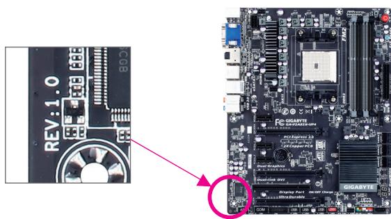
Table of Contents
Box Contents 6
Optional Items 6
GA-F2A85XN-WIFI Motherboard Layout. 7
GA-F2A85XN-WIFI Motherboard Block Diagram. 8
Chapter 1 Hardware Installation 9
1-1 Installation Precautions 9
1-2 Product Specifications 10
1-3 Installing the CPU and CPU cooler. 13
1-3-1 Installing the APU 13
1-3-2 Installing the APU cooler 15
1-4 Installing the Memory 16
1-4-1 Dual Channel Memory Configuration 16
1-4-2 Installing a Memory. 17
1-5 Installing an Expansion Card. 18
1-6 Setup of the AMD Dual Graphics Configuration 19
1-7 Back Panel Connectors 20
1-8 Internal Connectors 23
Chapter 2 BIOS Setup 31
2-1 Startup Screen 32
2-2 The Main Menu 33
2-3 M.I.T. 35
2-4 System 43
2-5 BIOS Features 44
2-6 Peripherals 47
2-7 Power Management 50
2-8 Save & Exit 52
Chapter 3 Drivers Installation 53
3-1 Configuring SATA Controllers. 53
3-2 Installing the SATA RAID/AHCI Driver and Operating System 63
Chapter 4 Drivers Installation 67
4-1 Installing Chipset Drivers 67
4-2 Application Software 68
4-3 Technical Manuals 68
4-4 Contact 69
4-5 System 69
4-6 Download Center 70
Chapter 5 Unique Features. 71
5-1 BIOS Update Utilities 71
5-1-1 Updating the BIOS with the Q-Flash Utility. 71
5-1-2 Updating the BIOS with the @BIOS Utility. 74
5-2 EasyTune 6 75
5-3 Smart Recovery 2. 76
5-4 Using the Wi-Fi/Bluetooth Utilities 78
5-4-1 Using the Wi-Fi Share Utility 78
5-4-2 Using the Cloud Station Utility 82
Chapter 6 Appendix 89
6-1 Configuring Audio Input and Output 89
6-1-1 Configuring 2/4/5.1/7.1-Channel Audio.. 89
6-1-2 Configuring S/PDIF Out. 91
6-1-3 Configuring Microphone Recording. 92
6-1-4 Using the Sound Recorder 94
6-2 Troubleshooting 95
6-2-1 Frequently Asked Questions 95
6-2-2 Troubleshooting Procedure 96
Regulatory Statements 98
Contact Us 103
Box Contents
GA-F2A85XN-WIFI motherboard
Motherboard driver disk
- Wireless module driver disk
User's Manual
Quick Installation Guide
Two SATA cables
I/O Shield
One antenna
The box contents above are for reference only and the actual items shall depend on the product package you obtain. The box contents are subject to change without notice.
Optional Items
□ 2-port USB 2.0 bracket (Part No. 12CR1-1UB030-6R)
eSATA bracket (Part No. 12CF1-3SATPW-4R)
3.5" Front Panel with 2 USB 3.0/2.0 ports (Part No. 12CR1-FPX582-2R)
□ HDMI-to-DVI adapter (Part No. 12CT2-HDMI01-1R)
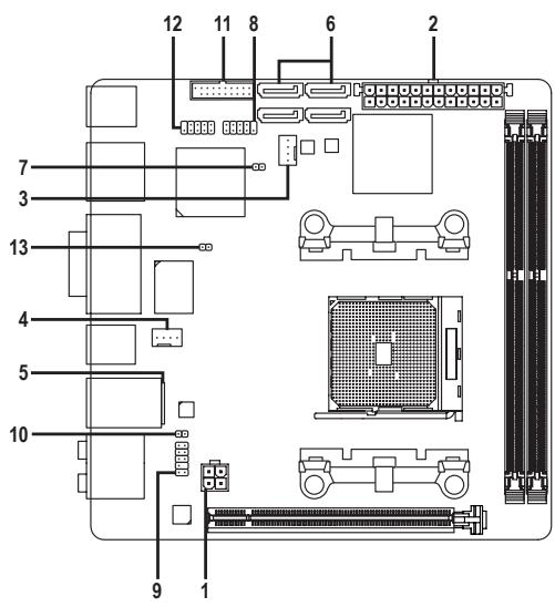
GA-F2A85XN-WIFI Motherboard Layout

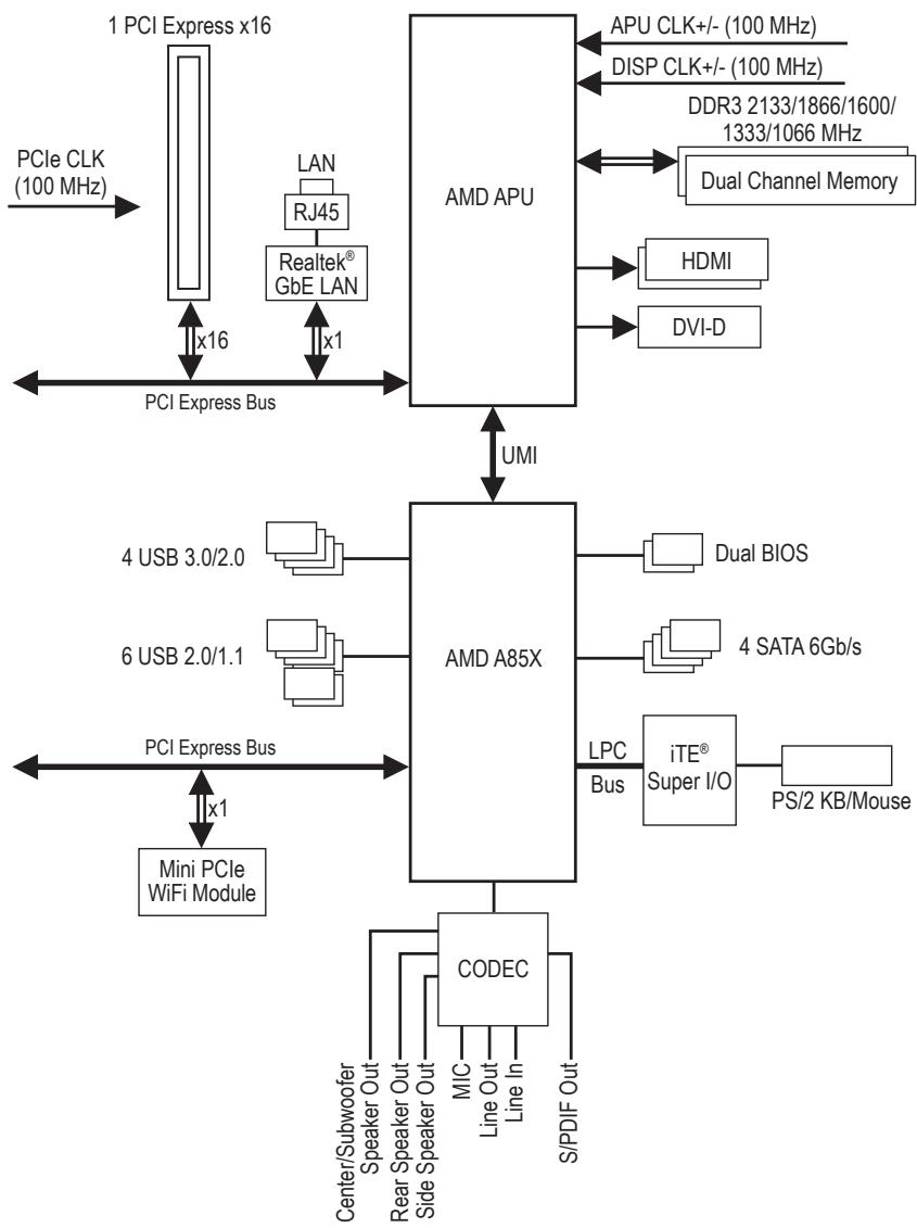
GA-F2A85XN-WIFI Motherboard Block Diagram
Chapter 1 Hardware Installation
1-1 Installation Precautions
The motherboard contains numerous delicate electronic circuits and components which can become damaged as a result of electrostatic discharge (ESD). Prior to installation, carefully read the user's manual and follow these procedures:
- Prior to installation, make sure the chassis is suitable for the motherboard.
- Prior to installation, do not remove or break motherboard S/N (Serial Number) sticker or warranty sticker provided by your dealer. These stickers are required for warranty validation.
- Always remove the AC power by unplugging the power cord from the power outlet before installing or removing the motherboard or other hardware components.
- When connecting hardware components to the internal connectors on the motherboard, make sure they are connected tightly and securely.
- When handling the motherboard, avoid touching any metal leads or connectors.
- It is best to wear an electrostatic discharge (ESD) wrist strap when handling electronic components such as a motherboard, CPU or memory. If you do not have an ESD wrist strap, keep your hands dry and first touch a metal object to eliminate static electricity.
- Prior to installing the motherboard, please have it on top of an antistatic pad or within an electrostatic shielding container.
- Before unplugging the power supply cable from the motherboard, make sure the power supply has been turned off.
- Before turning on the power, make sure the power supply voltage has been set according to the local voltage standard.
- Before using the product, please verify that all cables and power connectors of your hardware components are connected.
- To prevent damage to the motherboard, do not allow screws to come in contact with the motherboard circuit or its components.
- Make sure there are no leftover screws or metal components placed on the motherboard or within the computer casing.
- Do not place the computer system on an uneven surface.
- Do not place the computer system in a high-temperature environment.
- Turning on the computer power during the installation process can lead to damage to system components as well as physical harm to the user.
- If you are uncertain about any installation steps or have a problem related to the use of the product, please consult a certified computer technician.
1-2 Product Specifications
| APU | FM2 Socket: - AMD A series processors - AMD Athlon™ series processors (To GIGABYTE's website for the latest CPU support list.) |
| Chipset | AMD A85X |
| Memory | 2 x 1.5V DDR3 DIMM sockets supporting up to 64 GB of system memory * Due to a Windows 32-bit operating system limitation, when more than 4 GB of physical memory is installed, the actual memory size displayed will be less than the size of the physical memory installed. * The maximum 64 GB of system memory can be supported using 16 GB (or above) memory modules. GIGABYTE will update the memory support list on the official website when the memory modules are available on the market. Dual channel memory architecture Support for DDR3 2133/1866/1600/1333/1066 MHz memory modules Support for AMD Memory Profile (AMP)/Extreme Memory Profile (XMP) memory modules (To GIGABYTE's website for the latest supported memory speeds and memory modules.) |
| Onboard Graphics | APU with integrated AMD Radeon™ HD 8000/7000 series graphics: * To use the onboard graphics ports, you must install an AMD APU with integrated graphics. - 1 x DVI-D port, supporting a maximum resolution of 2560x1600 * Support for 2560x1600 resolution requires both a monitor and cable that support Dual Link DVI. * The DVI-D port does not support D-Sub connection by adapter. - 2 x HDMI ports, supporting a maximum resolution of 1920x1200 * Support for HDMI 1.4a version. - Support for DirectX 11 - Maximum shared memory of 2 GB |
| Audio | Realtek® ALC892 codec High Definition Audio 2/4/5.1/7.1-channel Support for S/PDIF Out |
| LAN | Realtek® GbE LAN chip (10/100/1000 Mbit) |
| Wireless Communication module | Wi-Fi 802.11 a/b/g/n, supporting 2.4/5 GHz Dual-Band Bluetooth 4.0, 3.0+HS, 2.1+EDR |
| Expansion Slots | 1 x PCI Express x16 slot, running at x16 (The PCI Express x16 slot conforms to PCI Express 2.0 standard.) 1 x mini-PCI Express slot for the wireless communication module |
| Multi-Graphics Technology | Support for AMD Dual Graphics technology * Only A series APUs support AMD Dual Graphics. |
| Storage Interface | Chipset: - 4 x SATA 6Gb/s connectors supporting up to 4 SATA 6Gb/s devices - Support for RAID 0, RAID 1, RAID 5, RAID 10, and JBOD |
| USB | Chipset: - Up to 4 USB 3.0/2.0 ports (2 ports on the back panel, 2 ports available through the internal USB header) - Up to 6 USB 2.0/1.1 ports (4 ports on the back panel, 2 ports available through the internal USB header) |
| Internal Connectors | 1 x 24-pin ATX main power connector 1 x 4-pin ATX 12V power connector 4 x SATA 6Gb/s connectors 1 x APU fan header 1 x system fan header 1 x front panel header 1 x front panel audio header 1 x S/PDIF Out header 1 x USB 3.0/2.0 header 1 x USB 2.0/1.1 header 1 x chassis intrusion header 1 x Clear CMOS jumper |
| Back Panel Connectors | 1 x PS/2 keyboard/mouse port 2 x HDMI ports 1 x DVI-D port 2 x antenna connectors 2 x USB 3.0/2.0 ports 4 x USB 2.0/1.1 ports 1 x RJ-45 port 1 x optical S/PDIF Out connector 5 x audio jacks (Center/Subwoofer Speaker Out, Rear Speaker Out, Line In, Line Out, Mic In) |
| I/O Controller | iTE® I/O Controller Chip |
| Hardware Monitor | System voltage detection APU/System temperature detection APU/System fan speed detection APU/System fan speed control * Whether the fan speed control function is supported will depend on the cooler you install. |
| BIOS | 2 x 64 Mbit flash Use of licensed AMI EFI BIOS Support for DualBIOSTM PnP 1.0a,DMI 2.0,SM BIOS 2.6,ACPI 2.0a |
| Unique Features | Support for @BIOS Support for Q-Flash Support for Xpress Install Support for EasyTune * Available functions in EasyTune may differ by motherboard model. Support for Smart Recovery 2 Support for ON/OFF Charge Support for Wi-Fi Share Support for Cloud Station |
| Bundled Software | Norton® Internet Security (OEM version) |
| Operating System | Support for Windows 8/7/Vista/XP * Support for Windows 8/7 only when an APU with integrated AMD Radeon™ HD 8000 series graphics is installed. |
| Form Factor | Mini-ITX Form Factor; 17.0cm x 17.0cm |
- GIGABYTE reserves the right to make any changes to the product specifications and product-related information without prior notice.
- Please visit the Support & Downloads\Utility page on GIGABYTE's website to check the supported operating system(s) for the software listed in the "Unique Features" and "Bundled Software" columns.
1-3 Installing the CPU and CPU Cooler

Read the following guidelines before you begin to install the APU:
- Make sure that the motherboard supports the APU. (Go to GIGABYTE's website for the latest APU support list.)
- Always turn off the computer and unplug the power cord from the power outlet before installing the APU to prevent hardware damage.
- Locate the pin one of the APU. The APU cannot be inserted if oriented incorrectly.
- Apply an even and thin layer of thermal grease on the surface of the APU.
- Do not turn on the computer if the APU cooler is not installed, otherwise overheating and damage of the APU may occur.
- Set the APU host frequency in accordance with the APU specifications. It is not recommended that the system bus frequency be set beyond hardware specifications since it does not meet the standard requirements for the peripherals. If you wish to set the frequency beyond the standard specifications, please do so according to your hardware specifications including the APU, graphics card, memory, hard drive, etc.
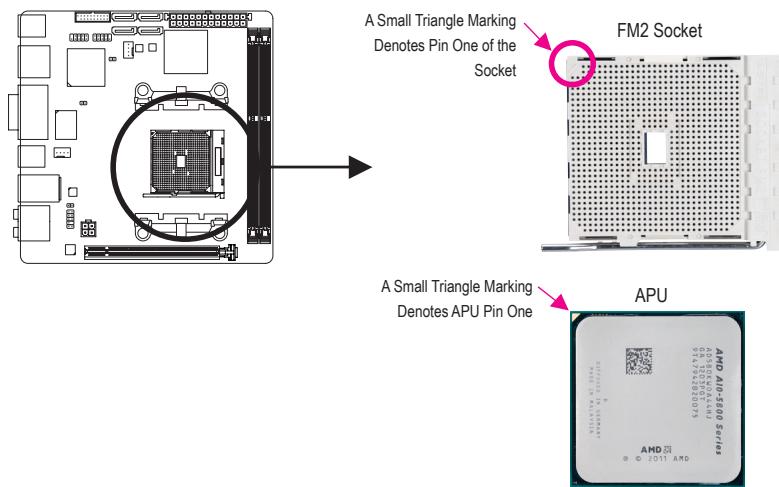
1-3-1 Installing the APU
A. Locate the alignment keys on the motherboard APU socket and the notches on the APU.
B. Follow the steps below to correctly install the APU into the motherboard APU socket.

- Before installing the APU, make sure to turn off the computer and unplug the power cord from the power outlet to prevent damage to the APU.
- Do not force the APU into the APU socket. The APU cannot fit in if oriented incorrectly. Adjust the APU orientation if this occurs.
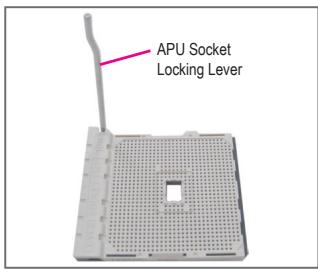
Step 1:
Completely lift up the APU socket locking lever.
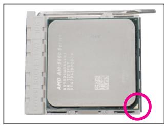
Step 2:
Align the APU pin one (small triangle marking) with the triangle mark on the APU socket and gently insert the APU into the socket. Make sure that the APU pins fit perfectly into their holes.
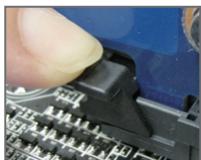
Once the APU is positioned into its socket, place one finger down on the middle of the APU, lowering the locking lever and latching it into the fully locked position.
1-3-2 Installing the APU cooler
Follow the steps below to correctly install the APU cooler on the motherboard.
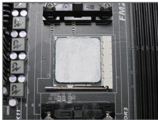
Step 1:
Apply an even and thin layer of thermal grease on the surface of the installed APU.
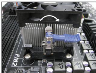
Step 3:
Turn the cam handle from the left side to the right side (as the picture above shows) to lock into place. (Refer to your APU cooler installation manual for instructions on installing the cooler.)
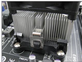
Step 2:
Hook the APU cooler clip to the mounting lug on one side of the retention frame. On the other side, push straight down on the APU cooler clip to hook it to the mounting lug on the retention frame.
Step 4:
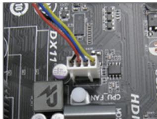
Finally, attach the power connector of the APU cooler to the APU fan header (CPU_FAN) on the motherboard.
1-4 Installing the Memory

Read the following guidelines before you begin to install the memory:
- Make sure that the motherboard supports the memory. It is recommended that memory of the same capacity, brand, speed, and chips be used. (Go to GIGABYTE's website for the latest supported memory speeds and memory modules.)
- Always turn off the computer and unplug the power cord from the power outlet before installing the memory to prevent hardware damage.
- Memory modules have a foolproof design. A memory module can be installed in only one direction. If you are unable to insert the memory, switch the direction.
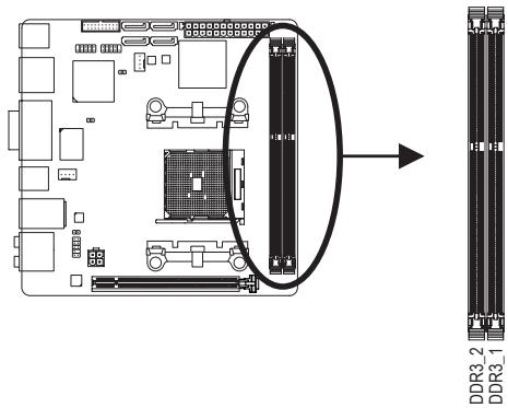
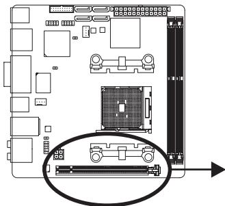
1-4-1 Dual Channel Memory Configuration
This motherboard provides two DDR3 memory sockets and supports Dual Channel Technology. After the memory is installed, the BIOS will automatically detect the specifications and capacity of the memory. Enabling Dual Channel memory mode will double the original memory bandwidth.
The two DDR3 memory sockets are divided into two channels and each channel has one memory socket as following:
Channel A: DDR3_1
Channel B: DDR3_2
Due to APU limitations, read the following guidelines before installing the memory in Dual Channel mode.
- Dual Channel mode cannot be enabled if only one DDR3 memory module is installed.
- When enabling Dual Channel mode with two memory modules, it is recommended that memory of the same capacity, brand, speed, and chips be used for optimum performance.
1-4-2 Installing a Memory

Before installing a memory module, make sure to turn off the computer and unplug the power cord from the power outlet to prevent damage to the memory module. DDR3 and DDR2 DIMMs are not compatible to each other or DDR DIMMs. Be sure to install DDR3 DIMMs on this motherboard.
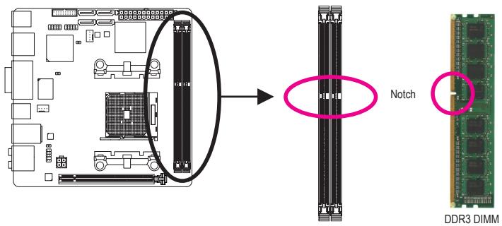
A DDR3 memory module has a notch, so it can only fit in one direction. Follow the steps below to correctly install your memory modules in the memory sockets.
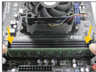
Step 1:
Note the orientation of the memory module. Spread the retaining clips at both ends of the memory socket. Place the memory module on the socket. As indicated in the picture on the left, place your fingers on the top edge of the memory, push down on the memory and insert it vertically into the memory socket.
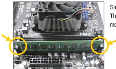
Step 2:
The clips at both ends of the socket will snap into place when the memory module is securely inserted.
1-5 Installing an Expansion Card

Read the following guidelines before you begin to install an expansion card:
- Make sure the motherboard supports the expansion card. Carefully read the manual that came with your expansion card.
- Always turn off the computer and unplug the power cord from the power outlet before installing an expansion card to prevent hardware damage.
Follow the steps below to correctly install your expansion card in the expansion slot.
- Locate an expansion slot that supports your card. Remove the metal slot cover from the chassis back panel.
- Align the card with the slot, and press down on the card until it is fully seated in the slot.
- Make sure the metal contacts on the card are completely inserted into the slot.
- Secure the card's metal bracket to the chassis back panel with a screw.
- After installing all expansion cards, replace the chassis cover(s).
- Turn on your computer. If necessary, go to BIOS Setup to make any required BIOS changes for your expansion card(s).
- Install the driver provided with the expansion card in your operating system.
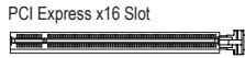
Example: Installing and Removing a PCI Express Graphics Card:
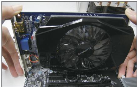
- Installing a Graphics Card:
Gently push down on the top edge of the card until it is fully inserted into the PCI Express slot. Make sure the card is securely seated in the slot and does not rock.
- Removing the Card:
Gently push back on the lever on the slot and then lift the card straight out from the slot.
1-6 Setup of the AMD Dual Graphics Configuration
Combining the onboard GPU with a discrete graphics card, AMD's Dual Graphics technology can provide significantly advanced display performance for AMD platform. Read the following instructions on configuring a Dual Graphics system.
A. System Requirements
AMD A series processor
- Windows 8/7 operating system
- An AMD Dual Graphics technology-supported motherboard (with the BIOS updated to the latest version) and correct driver (make sure the onboard graphics driver version is Rev. 8.981 or above)
- An AMD Radeon™ HD 6000 series graphics card that supports AMD Dual Graphics technology (for more details, please visit AMD's official website) and correct driver
B. Installing the Graphics Cards and Configuring BIOS Setup
Step 1:
Observe the steps in "1-5 Installing an Expansion Card" and install an AMD Dual Graphics technology-supported graphics card on the PCIeX16 slot. Plug the monitor cable into the graphics card and start up your computer.
Step 2:
Enter BIOS Setup to set the following items under the Peripherals\GFX Configuration menu:
- Set Integrated Graphics to Force.
- Set UMA Frame Buffer Size to 512M or above.
Save the settings and exit BIOS Setup. Restart your computer.
C. Configuring the Graphics Card Driver
After installing the graphics card driver in the operating system, go to the AMD VISION Engine Control Center. Browse to Performance\AMD Radeon™ Dual Graphics and ensure the Enable AMD Radeon Dual Graphics check box is selected.
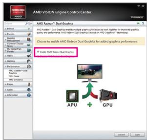
(Note) Make sure the drivers for the Chipset, onboard graphics, and external graphics card are properly installed.

Procedure and driver screen for enabling the AMD Dual Graphics technology may differ by graphics card and driver version. Refer to the manual that came with your graphics card for more information.
1-7 Back Panel Connectors
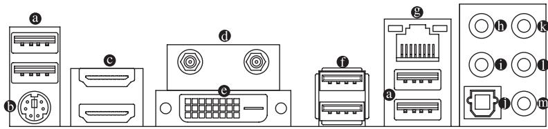
USB 2.0/1.1 Port
The USB port supports the USB 2.0/1.1 specification. Use this port for USB devices such as a USB keyboard/mouse, USB printer, USB flash drive and etc.
PS/2 Keyboard/Mouse Port
Use this port to connect a PS/2 mouse or keyboard.
HDMI Port

HIGH-DEFINITION MULTIMEDIA INTERFACE
The HDMI port is HDCP compliant and supports Dolby True HD and DTS HD
Master Audio formats. It also supports up to 192KHz/24bit 8-channel LPCM
audio output. You can use this port to connect your HDMI-supported monitor. The maximum supported resolution is 1920x1200, but the actual resolutions supported are dependent on the monitor being used.

After installing the HDMI device, make sure to set the default sound playback device to HDMI. (The item name may differ depending on your operating system. The screenshot below is from Windows 8.)
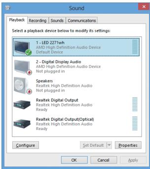
In Windows 8, select All apps>Control Panel>Hardware and Sound>Sound>Playback, set AMD High Definition Audio Device to the default playback device.
Antenna Connector
Use this connector to connect an antenna.
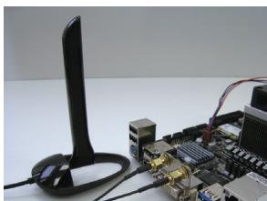
Tighten the antenna cables to the antenna connectors and then move the antenna to a place where the signal is good.
DVI-D Port (Note)
The DVI-D port conforms to the DVI-D specification and supports a maximum resolution of 2560x1600. Connect a monitor that supports DVI-D connection to this port. Please note that the actual resolutions supported are dependent on the monitor being used and support for 2560x1600 resolution requires both a monitor and cable that support Dual Link DVI.
A. Dual Display Configurations for the Onboard Graphics:
Dual display configurations are supported after you install motherboard drivers in OS.
B. Playback of Blu-ray™ Discs:
In order to get better playback quality, when playing the Blu-ray™ discs, refer to the recommended system requirements (or better) below.
AMD A series processors
Memory: Two 1 GB DDR3 1333 MHz memory modules with dual channel mode enabled
- BIOS Setup: At least 512 MB of UMA Frame Buffer Size (refer to Chapter 2, "BIOS Setup," "Peripherals\GFX Configuration," for more information)
- Playback software: CyberLink PowerDVD 10.0 or later (Note: Please ensure Hardware Acceleration is enabled. Whether Hardware Acceleration can be enabled for 3D Blu-ray discs is dependent on the APU being used.)
- HDCP compliant monitor(s)
USB 3.0/2.0 Port
The USB 3.0 port supports the USB 3.0 specification and is compatible to the USB 2.0/1.1 specification. Use this port for USB devices such as a USB keyboard/mouse, USB printer, USB flash drive and etc.
RJ-45 LAN Port
The Gigabit Ethernet LAN port provides Internet connection at up to 1 Gbps data rate. The following describes the states of the LAN port LEDs.
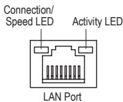
Connection/Speed LED:
| State | Description |
| Orange | 1 Gbps data rate |
| Green | 100 Mbps data rate |
| Off | 10 Mbps data rate |
Activity LED:
| State | Description |
| Blinking | Data transmission or receiving is occurring |
| Off | No data transmission or receiving is occurring |
(Note) The DVI-D port does not support D-Sub connection by adapter.
Center/Subwoofer Speaker Out Jack (Orange)
Use this audio jack to connect center/subwoofer speakers in a 5.1/7.1-channel audio configuration.
Rear Speaker Out Jack (Black)
This jack can be used to connect front speakers in a 4/5.1/7.1-channel audio configuration.
Optical S/PDIF Out Connector
This connector provides digital audio out to an external audio system that supports digital optical audio.
Before using this feature, ensure that your audio system provides an optical digital audio in connector.
Line In Jack (Blue)
The line out jack. Use this audio jack for line in devices such as an optical drive, walkman, etc.
Line Out Jack (Green)
The line out jack. Use this audio jack for a headphone or 2-channel speaker. This jack can be used to connect front speakers in a 4/5.1/7.1-channel audio configuration.
忍 Mic In Jack (Pink)
The default Mic in jack. Microphones must be connected to this jack.

The audio jacks can be reconfigured to perform different functions via the audio software (supported functions for each jack may vary based on hardware specification). If you install a Side Speaker, you need to retask other audio jack to be Side Speaker out. Only microphones still MUST be connected to the default Mic in jack. Refer to the instructions on setting up a 2/4/5.1/7.1-channel audio configuration in Chapter 6, "Configuring 2/4/5.1/7.1-Channel Audio."

- When removing the cable connected to a back panel connector, first remove the cable from your device and then remove it from the motherboard.
- When removing the cable, pull it straight out from the connector. Do not rock it side to side to prevent an electrical short inside the cable connector.
1-8 Internal Connectors
Read the following guidelines before connecting external devices:
- First make sure your devices are compliant with the connectors you wish to connect.
- Before installing the devices, be sure to turn off the devices and your computer. Unplug the power cord from the power outlet to prevent damage to the devices.
- After installing the device and before turning on the computer, make sure the device cable has been securely attached to the connector on the motherboard.
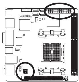
1/2) ATX_12V/ATX (2x2 12V Power Connector and 2x12 Main Power Connector)
With the use of the power connector, the power supply can supply enough stable power to all the components on the motherboard. Before connecting the power connector, first make sure the power supply is turned off and all devices are properly installed. The power connector possesses a foolproof design. Connect the power supply cable to the power connector in the correct orientation.
The 12V power connector mainly supplies power to the APU. If the 12V power connector is not connected, the computer will not start.

To meet expansion requirements, it is recommended that a power supply that can withstand high power consumption be used (300W or greater). If a power supply is used that does not provide the required power, the result can lead to an unstable or unbootable system.
ATX_12V
ATX_12V:
| Pin No. | Definition |
| 1 | GND |
| 2 | GND |
| 3 | +12V |
| 4 | +12V |

ATX:
| Pin No. | Definition | Pin No. | Definition |
| 1 | 3.3V | 13 | 3.3V |
| 2 | 3.3V | 14 | -12V |
| 3 | GND | 15 | GND |
| 4 | +5V | 16 | PS_ON (soft On/Off) |
| 5 | GND | 17 | GND |
| 6 | +5V | 18 | GND |
| 7 | GND | 19 | GND |
| 8 | Power Good | 20 | -5V |
| 9 | 5VSB (stand by +5V) | 21 | +5V |
| 10 | +12V | 22 | +5V |
| 11 | +12V (Only for 2x12-pin ATX) | 23 | +5V (Only for 2x12-pin ATX) |
| 12 | 3.3V (Only for 2x12-pin ATX) | 24 | GND (Only for 2x12-pin ATX) |
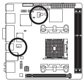
3/4) CPU_FAN/SYS_FAN (Fan Headers)
All fan headers on this motherboard are 4-pin. Most fan headers possess a foolproof insertion design. When connecting a fan cable, be sure to connect it in the correct orientation (the black connector wire is the ground wire). The speed control function requires the use of a fan with fan speed control design. For optimum heat dissipation, it is recommended that a system fan be installed inside the chassis.


CPU FAN:
| Pin No. | Definition |
| 1 | GND |
| 2 | +12V / Speed Control |
| 3 | Sense |
| 4 | Speed Control |
SYS_FAN:
| Pin No. | Definition |
| 1 | GND |
| 2 | +12V / Speed Control |
| 3 | Sense |
| 4 | VCC |

- Be sure to connect fan cables to the fan headers to prevent your APU and system from overheating. Overheating may result in damage to the APU or the system may hang.
These fan headers are not configuration jumper blocks. Do not place a jumper cap on the headers.
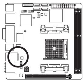
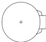
5) BAT (Battery)
The battery provides power to keep the values (such as BIOS configurations, date, and time information) in the CMOS when the computer is turned off. Replace the battery when the battery voltage drops to a low level, or the CMOS values may not be accurate or may be lost.
You may clear the CMOS values by removing the battery:
- Turn off your computer and unplug the power cord.
- Gently remove the battery from the battery holder and wait for one minute. (Or use a metal object like a screwdriver to touch the positive and negative terminals of the battery holder, making them short for 5 seconds.)
- Replace the battery.
- Plug in the power cord and restart your computer.

- Always turn off your computer and unplug the power cord before replacing the battery.
-
Replace the battery with an equivalent one. Danger of explosion if the battery is replaced with an incorrect model.
-
Contact the place of purchase or local dealer if you are not able to replace the battery by yourself or uncertain about the battery model.
- When installing the battery, note the orientation of the positive side (+) and the negative side (-) of the battery (the positive side should face up).
- Used batteries must be handled in accordance with local environmental regulations.
6) SATA3 0/1/2/3 (SATA 6Gb/s Connectors)
The SATA connectors conform to SATA 6Gb/s standard and are compatible with SATA 3Gb/s and SATA 1.5Gb/s standard. Each SATA connector supports a single SATA device. The AMD A85X Chipset supports RAID 0, RAID 1, RAID 5, RAID 10, and JBOD. Refer to Chapter 3, "Configuring SATA Hard Drive(s)," for instructions on configuring a RAID array.
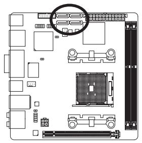
| Pin No. | Definition |
| 1 | GND |
| 2 | TXP |
| 3 | TXN |
| 4 | GND |
| 5 | RXN |
| 6 | RXP |
| 7 | GND |

- A RAID 0 or RAID 1 configuration requires at least two hard drives. If more than two hard drives are to be used, the total number of hard drives must be an even number.
- A RAID 5 configuration requires at least three hard drives. (The total number of hard drives does not have to be an even number.)
- A RAID 10 configuration requires four hard drives.
7) CLR_CMOS (Clear CMOS Jumper)
Use this jumper to clear the BIOS configuration and reset the CMOS values to factory defaults. To clear the CMOS values, use a metal object like a screwdriver to touch the two pins for a few seconds.

Open: Normal

Short: Clear CMOS Values

- Always turn off your computer and unplug the power cord from the power outlet before clearing the CMOS values.
- After system restart, go to BIOS Setup to load factory defaults (select Load Optimized Defaults) or manually configure the BIOS settings (refer to Chapter 2, "BIOS Setup," for BIOS configurations).
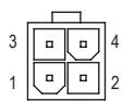
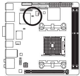
8) F PANEL (Front Panel Header)
Connect the power switch, reset switch, and system status indicator on the chassis to this header according to the pin assignments below. Note the positive and negative pins before connecting the cables.
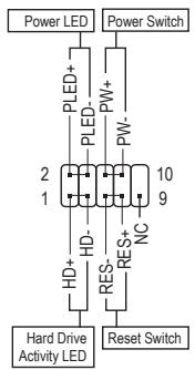
- PLED (Power LED, Yellow):
| System Status | LED |
| S0 | On |
| S3/S4/S5 | Off |
Connects to the power status indicator on the chassis front panel. The LED is on when the system is operating. The LED is off when the system is in S3/ S4 sleep state or powered off (S5).
- PW (Power Switch, Red):
Connects to the power switch on the chassis front panel. You may configure the way to turn off your system using the power switch (refer to Chapter 2, "BIOS Setup," "Power Management," for more information).
- HD (Hard Drive Activity LED, Blue):
Connects to the hard drive activity LED on the chassis front panel. The LED is on when the hard drive is reading or writing data.
- RES (Reset Switch, Green):
Connects to the reset switch on the chassis front panel. Press the reset switch to restart the computer if the computer freezes and fails to perform a normal restart.
NC (Purple):
No connection.

The front panel design may differ by chassis. A front panel module mainly consists of power switch, reset switch, power LED, hard drive activity LED and etc. When connecting your chassis front panel module to this header, make sure the wire assignments and the pin assignments are matched correctly.
9) F_AUDIO (Front Panel Audio Header)
The front panel audio header supports Intel High Definition audio (HD) and AC'97 audio. You may connect your chassis front panel audio module to this header. Make sure the wire assignments of the module connector match the pin assignments of the motherboard header. Incorrect connection between the module connector and the motherboard header will make the device unable to work or even damage it.
For HD Front Panel Audio:
| Pin No. | Definition |
| 1 | MIC2_L |
| 2 | GND |
| 3 | MIC2_R |
| 4 | -ACZ_DET |
| 5 | LINE2_R |
| 6 | GND |
| 7 | FAUDIO_JD |
| 8 | No Pin |
| 9 | LINE2_L |
| 10 | GND |
For AC'97 Front Panel Audio:
| Pin No. | Definition |
| 1 | MIC |
| 2 | GND |
| 3 | MIC Power |
| 4 | NC |
| 5 | Line Out (R) |
| 6 | NC |
| 7 | NC |
| 8 | No Pin |
| 9 | Line Out (L) |
| 10 | NC |

The front panel audio header supports HD audio by default. If your chassis provides an AC'97 front panel audio module, refer to the instructions on how to activate AC'97 functionality via the audio software in Chapter 6, "Configuring 2/4/5.1/7.1-Channel Audio."
- Audio signals will be present on both of the front and back panel audio connections simultaneously. If you want to mute the back panel audio (only supported when using an HD front panel audio module), refer to Chapter 6, "Configuring 2/4/5.1/7.1-Channel Audio."
- Some chassis provide a front panel audio module that has separated connectors on each wire instead of a single plug. For information about connecting the front panel audio module that has different wire assignments, please contact the chassis manufacturer.
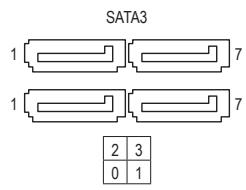
10) SPDIF_O (S/PDIF Out Header)
This header supports digital S/PDIF Out and connects a S/PDIF digital audio cable (provided by expansion cards) for digital audio output from your motherboard to certain expansion cards like graphics cards and sound cards. For example, some graphics cards may require you to use a S/PDIF digital audio cable for digital audio output from your motherboard to your graphics card if you wish to connect an HDMI display to the graphics card and have digital audio output from the HDMI display at the same time.
For information about connecting the S/PDIF digital audio cable, carefully read the manual for your expansion card.
1
| Pin No. | Definition |
| 1 | SPDIFO |
| 2 | GND |
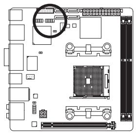
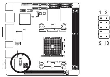
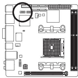
11) F_USB30 (USB 3.0/2.0 Header)
The header conforms to USB 3.0/2.0 specification and can provide two USB ports. For purchasing the optional 3.5" front panel that provides two USB 3.0/2.0 ports, please contact the local dealer.
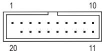
| Pin No. | Definition | Pin No. | Definition |
| 1 | VBUS | 11 | D2+ |
| 2 | SSRX1- | 12 | D2- |
| 3 | SSRX1+ | 13 | GND |
| 4 | GND | 14 | SSTX2+ |
| 5 | SSTX1- | 15 | SSTX2- |
| 6 | SSTX1+ | 16 | GND |
| 7 | GND | 17 | SSRX2+ |
| 8 | D1- | 18 | SSRX2- |
| 9 | D1+ | 19 | VBUS |
| 10 | NC | 20 | No Pin |
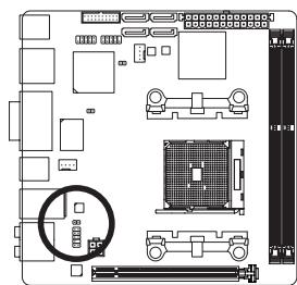
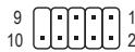
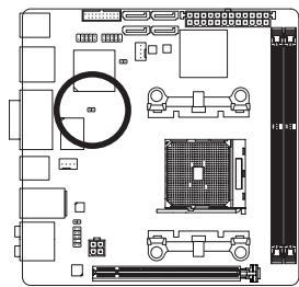
12) F_USB1 (USB 2.0/1.1 Header)
The header conforms to USB 2.0/1.1 specification. Each USB header can provide two USB ports via an optional USB bracket. For purchasing the optional USB bracket, please contact the local dealer.
| Pin No. | Definition |
| 1 | Power (5V) |
| 2 | Power (5V) |
| 3 | USB DX- |
| 4 | USB DY- |
| 5 | USB DX+ |
| 6 | USB DY+ |
| 7 | GND |
| 8 | GND |
| 9 | No Pin |
| 10 | NC |

- Do not plug the IEEE 1394 bracket (2x5-pin) cable into the USB 2.0/1.1 header.
- Prior to installing the USB bracket, be sure to turn off your computer and unplug the power cord from the power outlet to prevent damage to the USB bracket.
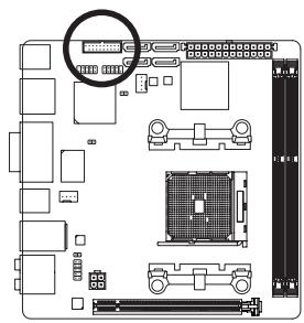
13) CI (Chassis Intrusion Header)
This motherboard provides a chassis detection feature that detects if the chassis cover has been removed. This function requires a chassis with chassis intrusion detection design.
1
| Pin No. | Definition |
| 1 | Signal |
| 2 | GND |
Chapter 2 BIOS Setup
BIOS (Basic Input and Output System) records hardware parameters of the system in the CMOS on the motherboard. Its major functions include conducting the Power-On Self-Test (POST) during system startup, saving system parameters and loading operating system, etc. BIOS includes a BIOS Setup program that allows the user to modify basic system configuration settings or to activate certain system features.
When the power is turned off, the battery on the motherboard supplies the necessary power to the CMOS to keep the configuration values in the CMOS.
To access the BIOS Setup program, press the
To upgrade the BIOS, use either the GIGABYTE Q-Flash or @BIOS utility.
Q-Flash allows the user to quickly and easily upgrade or back up BIOS without entering the operating system.
- @BIOS is a Windows-based utility that searches and downloads the latest version of BIOS from the Internet and updates the BIOS.
For instructions on using the Q-Flash and @BIOS utilities, refer to Chapter 5, "BIOS Update Utilities."

- Because BIOS flashing is potentially risky, if you do not encounter problems using the current version of BIOS, it is recommended that you not flash the BIOS. To flash the BIOS, do it with caution. Inadequate BIOS flashing may result in system malfunction.
- It is recommended that you not alter the default settings (unless you need to) to prevent system instability or other unexpected results. Inadequately altering the settings may result in system's failure to boot. If this occurs, try to clear the CMOS values and reset the board to default values. (Refer to the "Load Optimized Defaults" section in this chapter or introductions of the battery/clear CMOS jumper in Chapter 1 for how to clear the CMOS values.)
2-1 Startup Screen
The following startup Logo screen will appear when the computer boots.

DEL:BIOSSETUP\Q-FLASH F9:SYSTEMINFORMATION F12:BOOTMENU END:Q-FLASH
Function Keys
Function Keys:
: BIOS SETUP\Q-FLASH
Press the
Press the <F9> key to display your system information.
Boot Menu allows you to set the first boot device without entering BIOS Setup. In Boot Menu, use the up arrow key <> or the down arrow key <> to select the first boot device, then press
Note: The setting in Boot Menu is effective for one time only. After system restart, the device boot order will still be based on BIOS Setup settings.
Press the
2-2 The Main Menu
On the main menu of the BIOS Setup program, press arrow keys to move among the items and press
(Sample BIOS Version: F1i)
BIOS Setup Program Function Keys
| <←><→> | Move the selection bar to select a setup menu |
| <↑><↓> | Move the selection bar to select an configuration item on a menu |
| <Enter> | Execute command or enter a menu |
| <+/>/<Page Up> | Increase the numeric value or make changes |
| <->/<Page Down> | Decrease the numeric value or make changes |
| <F5> | Restore the previous BIOS settings for the current submenus |
| <F7> | Load the Optimized BIOS default settings for the current submenus |
| <F8> | Access the Q-Flash utility |
| <F9> | Display system information |
| <F10> | Save all the changes and exit the BIOS Setup program |
| <F12> | Capture the current screen as an image and save it to your USB drive |
| <Esc> | Main Menu: Exit the BIOS Setup program Submenus: Exit current submenu |
BIOS Setup Menus
M.I.T.
Use this menu to configure the clock, frequency, and voltages of your CPU and memory, etc. Or check the system/CPU temperatures, voltages, and fan speeds.
System
Use this menu to configure the default language used by the BIOS and system time and date. This menu also displays information on the devices connected to the SATA ports.
BIOS Features
Use this menu to configure the device boot order, advanced features available on the CPU, and the primary display adapter.
Peripherals
Use this menu to configure all peripheral devices, such as SATA, USB, integrated audio, and integrated LAN, etc.
Power Management
Use this menu to configure all the power-saving functions.
Save & Exit
Save all the changes made in the BIOS Setup program to the CMOS and exit BIOS Setup. You can save the current BIOS settings to a profile or load optimized defaults for optimal-performance system operations.

- When the system is not stable as usual, select the Load Optimized Defaults item to set your system to its defaults.
- The BIOS Setup menus described in this chapter are for reference only and may differ by BIOS version.
2-3 M.I.T.
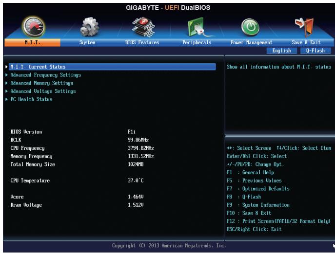

Whether the system will work stably with the overclock/overvoltage settings you made is dependent on your overall system configurations. Incorrectly doing overclock/overvoltage may result in damage to CPU, chipset, or memory and reduce the useful life of these components. This page is for advanced users only and we recommend you not to alter the default settings to prevent system instability or other unexpected results. (Inadequately altering the settings may result in system's failure to boot. If this occurs, clear the CMOS values and reset the board to default values.)
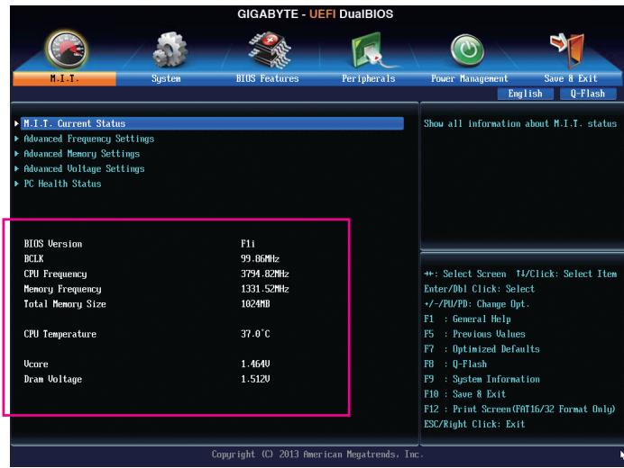
This section provides information on the BIOS version, CPU base clock, CPU frequency, memory frequency, total memory size, CPU temperature, Vcore, and memory voltage.
M.I.T. Current Status
This screen provides information on CPU/memory frequencies/parameters.
Advanced Frequency Settings
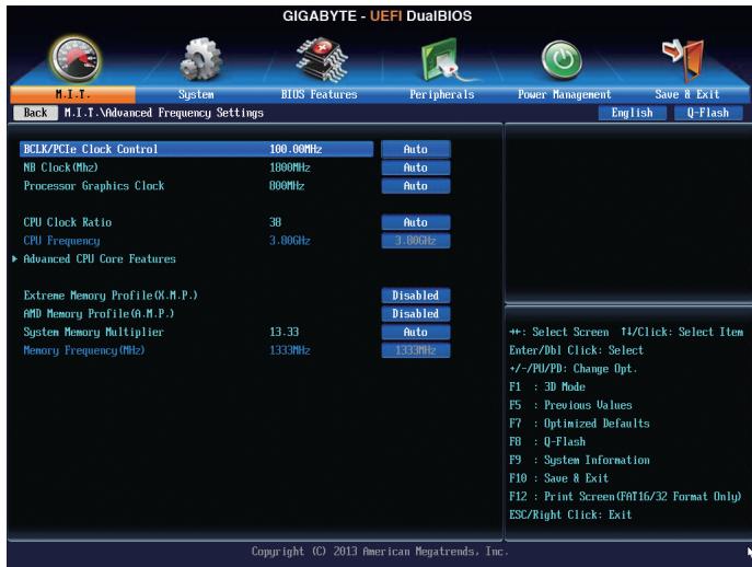
BCLK/PCle Clock Control
Allows you to manually set the CPU base clock and PCIe bus frequency in 1 MHz increments. (Default: Auto)
Important: It is highly recommended that the CPU frequency be set in accordance with the CPU specifications.
NB Clock(Mhz)
Allows you to manually set the CPU North Bridge frequency. The adjustable range is from 800 MHz to 6000 MHz.
Processor Graphics Clock
Allows you to set the onboard graphics clock. The adjustable range is from 300 MHz to 2000 MHz.
CPU Clock Ratio
Allows you to alter the clock ratio for the installed CPU. The adjustable range is dependent on the CPU being installed.
CPU Frequency
Displays the current operating CPU frequency.
Advanced CPU Core Features
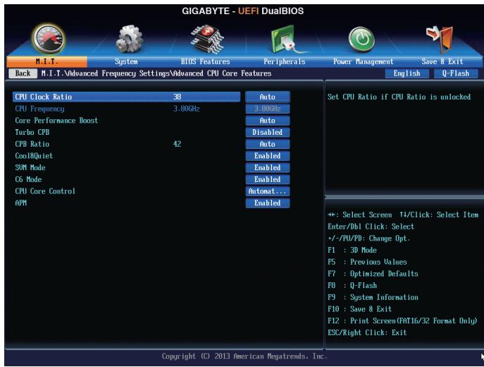
CPU Clock Ratio, CPU Frequency
The settings above are synchronous to those under the same items on the Advanced Frequency Settings menu.
Core Performance Boost (Note)
Allows you to determine whether to enable the Core Performance Boost (CPB) technology, a CPU performance-boost technology. (Default: Auto)
Turbo CPB (Note)
Allows you to determine whether to improve CPU performance. (Default: Disabled)
CPB Ratio (Note)
Allows you alter the ratio for the CPB. The adjustable range is dependent on the CPU being installed. (Default: Auto)
Cool&Quiet
▶ Enabled Let's the AMD Cool'n'Quiet driver dynamically adjust the CPU clock and VID to reduce heat output from your computer and its power consumption. (Default)
Disabled Disables this function.
SVM Mode
Virtualization enhanced by Virtualization Technology will allow a platform to run multiple operating systems and applications in independent partitions. With virtualization, one computer system can function as multiple virtual systems. (Default: Enabled)
C6 Mode
Allows you to determine whether to let the CPU enter C6 mode in system halt state. When enabled, the CPU core frequency will be reduced during systemhalt state to decrease power consumption. The C6 state is a more enhanced power-saving state than C1. (Default: Enabled)
(Note) This item is present only when you install a CPU that supports this feature.
CPU core Control
Allows you to determine whether to manually enable/disable CPU cores. Automatic mode allows the BIOS to enable all CPU cores (number of cores available depends on the CPU being used). (Default: Automatic mode)
APM
Enables or disables Application Power Management. (Default: Enabled)
Extreme Memory Profile (X.M.P.) (Note)
Allows the BIOS to read the SPD data on XMP memory module(s) to enhance memory performance when enabled.
Disabled Disables this function. (Default)
Profile1 Uses Profile 1 settings.
Profile2 (Note 2) Uses Profile 2 settings.
AMD Memory Profile (A.M.P.) (Note)
Allows the BIOS to read the SPD data on AMP memory module(s) to enhance memory performance when enabled. (Default: Disabled)
System Memory Multiplier
Allows you to set the system memory multiplier. Auto sets memory multiplier according to memory SPD data. (Default: Auto)
Memory Frequency (MHz)
This value is automatically adjusted according to the BCLK Clock Control and System Memory Multiplier settings.
(Note) This item is present only when you install a memory module that supports this feature.
Advanced Memory Settings
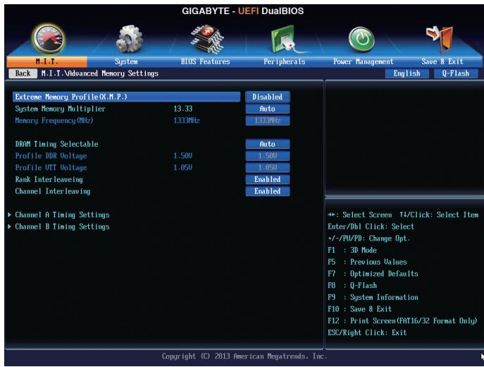
Extreme Memory Profile (X.M.P.) (Note), System Memory Multiplier, Memory Frequency(MHz) The settings above are synchronous to those under the same items on the Advanced Frequency Settings menu.
DRAM Timing Selectable
Quick and Expert allows the memory timing settings below to be configurable. Options are: Auto (default), Quick, Expert.
Profile DDR Voltage
When using a non-XMP memory module or Extreme Memory Profile (X.M.P.) is set to Disabled, this item will display as 1.50V. When Extreme Memory Profile (X.M.P.) is set to Profile1 or Profile2, this item will display the value based on the SPD data on the XMP memory.
Profile VTT Voltage
The value displayed here is dependent on the CPU being used.
Rank Interleaving
Enables or disables memory rank interleaving. Enabled allows the system to simultaneously access different ranks of the memory to increase memory performance and stability. Auto lets the BIOS automatically configure this setting. (Default: Auto)
Channel Interleaving
Enables or disables memory channel interleaving. Enabled allows the system to simultaneously access different channels of the memory to increase memory performance and stability. Auto lets the BIOS automatically configure this setting. (Default: Auto)
(Note) This item is present only when you install a memory module that supports this feature.
Channel A/B Timing Settings
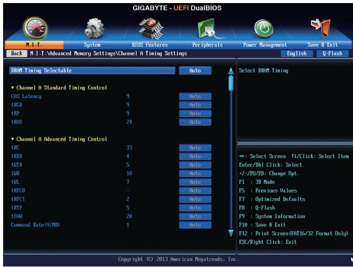
This sub-menu provides memory timing settings for each channel of memory. The respective timing setting screens are configurable only when DRAM Timing Selectable is set to Quick or Expert. Note: Your system may become unstable or fail to boot after you make changes on the memory timings. If this occurs, please reset the board to default values by loading optimized defaults or clearing the CMOS values.
Advanced Voltage Settings
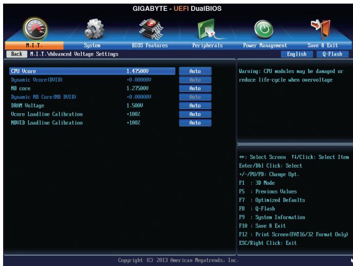
This sub-menu allows you to set CPU, chipset and memory voltages.
PC Health Status
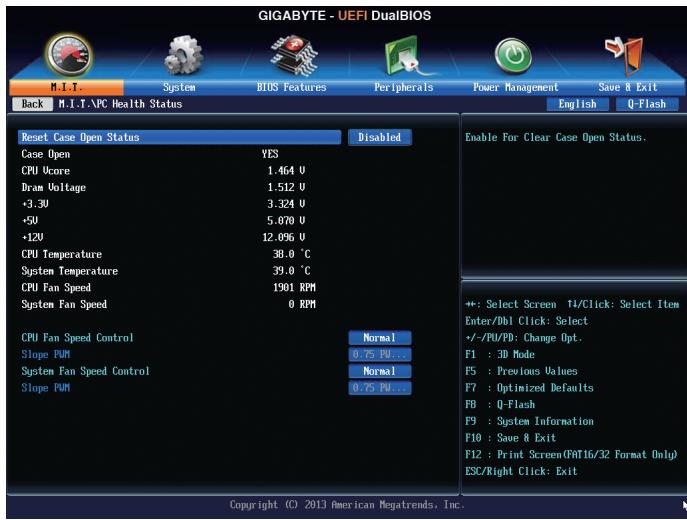
Reset Case Open Status
Disabled Keeps or clears the record of previous chassis intrusion status. (Default)
▶ Enabled Clears the record of previous chassis intrusion status and the Case Open field will show "No" at next boot.
Case Open
Displays the detection status of the chassis intrusion detection device attached to the motherboard CI header. If the system chassis cover is removed, this field will show "Yes", otherwise it will show "No". To clear the chassis intrusion status record, set Reset Case Open Status to Enabled, save the settings to the CMOS, and then restart your system.
CPU Vcore/Dram Voltage/ +3.3V / + 5V / + 12V
Displays the current system voltages.
CPU/System Temperature
Displays current CPU/system temperature.
CPU/System Fan Speed
Displays current CPU/system/power fan speed.
CPU Fan Speed Control
Allows you to determine whether to enable the fan speed control function and adjust the fan speed.
Normal Allows the fan to run at different speeds according to the CPU temperature. You can adjust the fan speed with EasyTune based on your system requirements. (Default)
Silent Allows the fan to run at slow speeds.
→ Manual Allows you to control the fan speed under the Slope PWM item.
Disabled Allows the fan to run at full speeds.
Slope PWM
Allows you to control the CPU fan speed. This item is configurable only when CPU Fan Speed Control is set to Manual. Options are: 0.75 PWM value /°C ~ 2.50 PWM value /°C.
System Fan Speed Control
Allows you to determine whether to enable the fan speed control function and adjust the fan speed.
Normal Allows the fan to run at different speeds according to the system temperature. You can adjust the fan speed with EasyTune based on your system requirements. (Default)
Silent Allows the fan to run at slow speeds.
→ Manual Allows you to control the fan speed under the Slope PWM item.
Disabled Allows the fan to run at full speeds.
Slope PWM
Allows you to control the system fan speed. This item is configurable only when System Fan Speed Control is set to Manual. Options are: 0.75 PWM value /°C ~ 2.50 PWM value /°C.
2-4 System
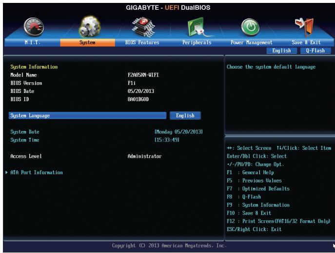
This section provides information on your motherboard model and BIOS version. You can also select the default language used by the BIOS and manually set the system time.
System Language
Selects the default language used by the BIOS.
System Date
Sets the system date. The date format is week (read-only), month, date, and year. Use
System Time
Sets the system time. The time format is hour, minute, and second. For example, 1 p.m. is 13:0:0. Use
Access Level
Displays the current access level depending on the type of password protection used. (If no password is set, the default will display as Administrator.) The Administrator level allows you to make changes to all BIOS settings; the User level only allows you to make changes to certain BIOS settings but not all.
ATA Port Information
This section provides information on the device connected to each SATA port controlled by AMD Chipset.
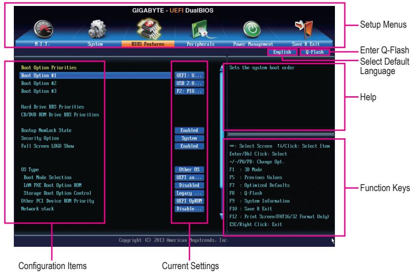
2-5 BIOS Features
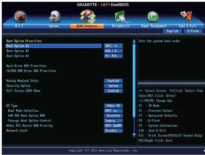
Boot Option Priorities
Specifies the overall boot order from the available devices. For example, you can set hard drive as the first priority (Boot Option #1) and DVD ROM drive as the second priority (Boot Option #2). The list only displays the device with the highest priority for a specific type. For example, only hard drive defined as the first priority on the Hard Drive BBS Priorities menu will be presented here.
Removable storage devices that support GPT format will be prefixed with "UEFI:" string on the boot device list. To boot from an operating system that supports GPT partitioning, select the device prefixed with "UEFI:" string.
Or if you want to install an operating system that supports GPT partitioning such as Windows 7 64-bit, select the optical drive that contains the Windows 7 64-bit installation disk and is prefixed with "UEFI:" string.
Hard Drive/CD/DVD ROM Drive/Floppy Drive/Network Device BBS Priorities
Specifies the boot order for a specific device type, such as hard drives, optical drives, floppy disk drives, and devices that support Boot from LAN function, etc. Press
Bootup NumLock State
Enables or disables Numlock feature on the numeric keypad of the keyboard after the POST. (Default: Enabled)
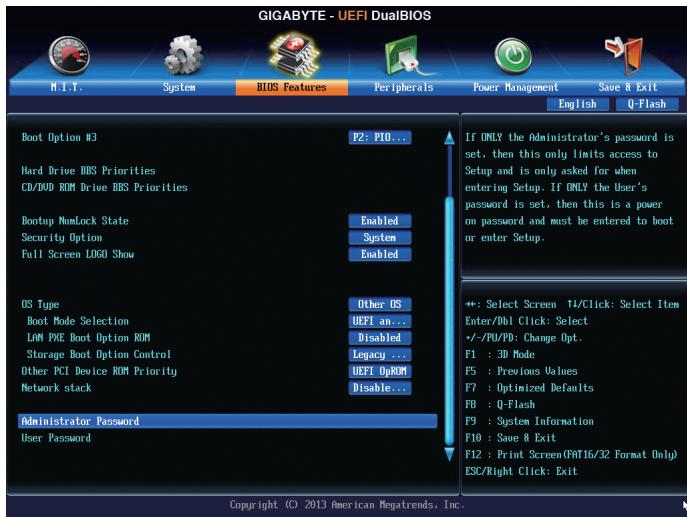
Security Option
Specifies whether a password is required every time the system boots, or only when you enter BIOS Setup.
After configuring this item, set the password(s) under the Administrator Password/User Password item.
Setup A password is only required for entering the BIOS Setup program.
System A password is required for booting the system and for entering the BIOS Setup program. (Default)
Full Screen LOGO Show
Allows you to determine whether to display the GIGABYTE Logo at system startup. Disabled skips the GIGABYTE Logo when the system starts up. (Default: Enabled)
OS Type
Allows you to select the operating system to be installed. (Default: Other OS)
CSM Support
Enables or disables UEFI CSM (Compatibility Support Module) to support a legacy PC boot process.
Always Enables UEFI CSM. (Default)
Never Disables UEFI CSM and supports UEFI BIOS boot process only.
This item is configurable only when OS Type is set to Windows 8.
Boot Mode Selection
Allows you to select which type of operating system to boot.
UEFI and Legacy Allows booting from operating systems that support legacy option ROM or UEFI option ROM. (Default)
Legacy Only Allows booting from operating systems that only support legacy Option ROM.
UEFI Only Allows booting from operating systems that only support UEFI Option ROM.
This item is configurable only when CSM Support is set to Always.
LAN PXE Boot Option ROM
Allows you to select whether to enable the legacy option ROM for the LAN controller. (Default: Disabled)
This item is configurable only when CSM Support is set to Always.
Storage Boot Option Control
Allows you to select whether to enable the UEFI or legacy option ROM for the storage device controller.
Disabled Disables option ROM.
Legacy Only Enables legacy option ROM only. (Default)
UEFI Only Enables UEFI option ROM only.
Legacy First Enables legacy option ROM first.
UEFI First Enables UEFI option ROM first.
This item is configurable only when CSM Support is set to Always.
Other PCI Device ROM Priority
Allows you to select whether to enable the UEFI or Legacy option ROM for the PCI device controller other than the LAN, storage device, and graphics controllers.
Legacy OpROM Enables legacy option ROM only.
UEFI OpROM Enables UEFI option ROM only. (Default)
Network stack
Disables or enables booting from the network to install a GPT format OS, such as installing the OS from the Windows Deployment Services server. (Default: Disable Link)
Ipv4 PXE Support
Enables or disables IPv4 PXE Support. This item is configurable only when Network stack is enabled.
Ipv6 PXE Support
Enables or disables IPv6 PXE Support. This item is configurable only when Network stack is enabled.
Administrator Password
Allows you to configure an administrator password. Press
User Password
Allows you to configure a user password. Press
To cancel the password, press
2-6 Peripherals
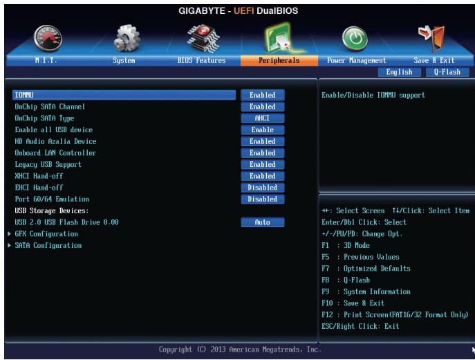
IOMMU
Enables or disables AMD IOMMU support. (Default: Disabled)
OnChip SATA Controller
Enables or disables the integrated SATA controllers. (Default: Enabled)
OnChip SATA Type
Enables or disables RAID for the SATA controllers integrated in the Chipset or configures the SATA controllers to AHCI mode.
Native IDE Configures the SATA controller to IDE mode.
RAID Enables RAID for the SATA controller.
AHCI Configures the SATA controllers to AHCI mode. Advanced Host Controller Interface (AHCI) is an interface specification that allows the storage driver to enable advanced Serial ATA features such as Native Command Queuing and hot plug. (Default)
Enable all USB devices
Enables or disables the integrated USB controller. (Default: Enabled)
HD Audio Azalia Device
Enables or disables the onboard audio function. (Default: Enabled)
If you wish to install a 3rd party add-in audio card instead of using the onboard audio, set this item to Disabled.
Onboard LAN Controller
Enables or disables the onboard LAN function. (Default: Enabled)
If you wish to install a 3rd party add-in network card instead of using the onboard LAN, set this item to Disabled.
Legacy USB Support
Allows USB keyboard/mouse to be used in MS-DOS. (Default: Enabled)
XHCl Hand-off
Determines whether to enable XHCI Hand-off feature for an operating system without XHCI Hand-off support. (Default: Enabled)
EHCI Hand-off
Determines whether to enable XHCI Hand-off feature for an operating system without XHCI Hand-off support. (Default: Disabled)
Port 60/64 Emulation
Enables or disables emulation of I/O ports 64h and 60h. This should be enabled for full legacy support for USB keyboards/mice in MS-DOS or in operating system that does not natively support USB devices. (Default: Disabled)
USB Storage Devices
Displays a list of connected USB mass storage devices. This item appears only when a USB storage device is installed.
GFX Configuration
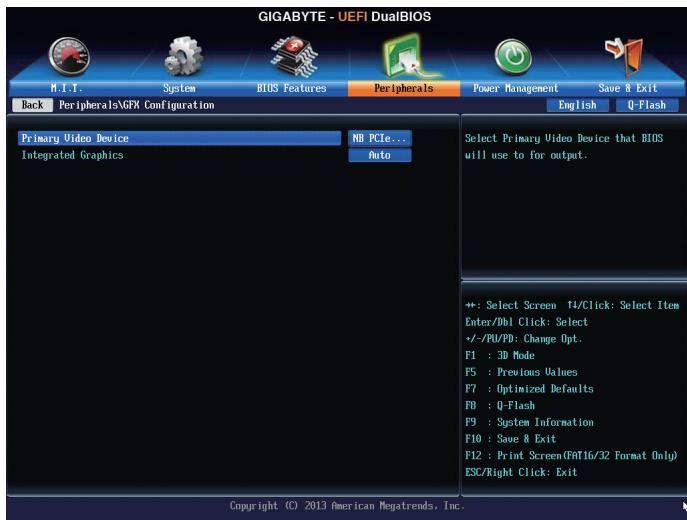
Primary Video Device
Specifies the first initiation of the monitor display from the installed PCI Express graphics card or the onboard graphics.
IGD Video Sets the onboard graphics as the first display.
NB PCIe Slot Video Sets the PCI Express graphics card on the PCI Express slot controlled by the North Bridge as the first display. (Default)
Integrated Graphics
Enables or disables the onboard graphics function.
Auto The BIOS will automatically enable or disable the onboard graphics depending on the graphics card being installed. (Default)
Disabled Disables the onboard graphics.
Force Always activates the onboard graphics, whether or not a PCI Express card is installed.
UMA Frame Buffer Size
This item is configurable only when Integrated Graphics is set to Force. Frame buffer size is the total amount of system memory allocated solely for the onboard graphics controller. MS-DOS, for example, will use only this memory for display. Options are: Auto (default), 256M, 512M, 1G, 2G.
SATA Configuration
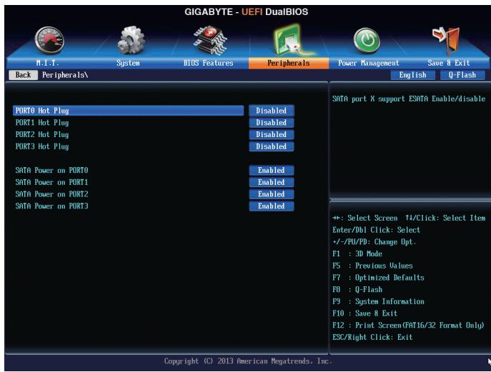
SATA Hot Plug on PORT0~SATA Hot Plug on PORT3
Enables or disable the hot plug capability for each SATA port. (Default: Disabled)
SATA Power on PORT0~SATA Power on PORT3
Enables or disables each SATA port. (Default: Enabled)
2-7 Power Management
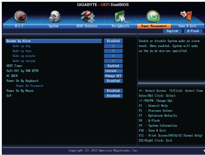
Resume by Alarm
Determines whether to power on the system at a desired time. (Default: Disabled)
If enabled, set the date and time as following:
Wake up day: Turn on the system at a specific time on each day or on a specific day in a month.
Wake up hour/minute/second: Set the time at which the system will be powered on automatically.
Note: When using this function, avoid inadequate shutdown from the operating system or removal of the AC power, or the settings may not be effective.
HPET Support
Enables or disables High Precision Event Timer (HPET) for Windows 8/7/Vista operating system. (Default: Enabled)
Soft-Off by PWR-BTTN
Configures the way to turn off the computer in MS-DOS mode using the power button.
Instant-Off Press the power button and then the system will be turned off instantly. (Default)
Delay 4 Sec Press and hold the power button for 4 seconds to turn off the system. If the power button is pressed for less than 4 seconds, the system will enter suspend mode.
AC BACK
Determines the state of the system after the return of power from an AC power loss.
Memory The system returns to its last known awake state upon the return of the AC power.
Always On The system is turned on upon the return of the AC power.
Always Off The system stays off upon the return of the AC power. (Default)
(Note) Supported on Windows 8/7/Vista operating system only.
Power On By Keyboard
Allows the system to be turned on by a PS/2 keyboard wake-up event.
Note: To use this function, you need an ATX power supply providing at least 1A on the +5VSB lead.
Disabled Disables this function. (Default)
Password Set a password with 1-5 characters to turn on the system.
▶ Keyboard 98 Press POWER button on the Windows 98 keyboard to turn on the system.
Any key Press any key to turn on the system.
Power On Password
Set the password when Power On By Keyboard is set to Password.
Press
Note: To cancel the password, press
Power On By Mouse
Allows the system to be turned on by a PS/2 mouse wake-up event.
Note: To use this function, you need an ATX power supply providing at least 1A on the +5VSB lead.
Disabled Disables this function. (Default)
Move Move the mouse to turn on the system.
Double Click Double click on left button on the mouse to turn on the system.
ErP
Determines whether to let the system consume least power in S5 (shutdown) state. (Default: Disabled) Note: When this item is set to Enabled, the following functions will become unavailable: PME event wake up, power on by mouse, power on by keyboard, and wake on LAN.
2-8 Save & Exit
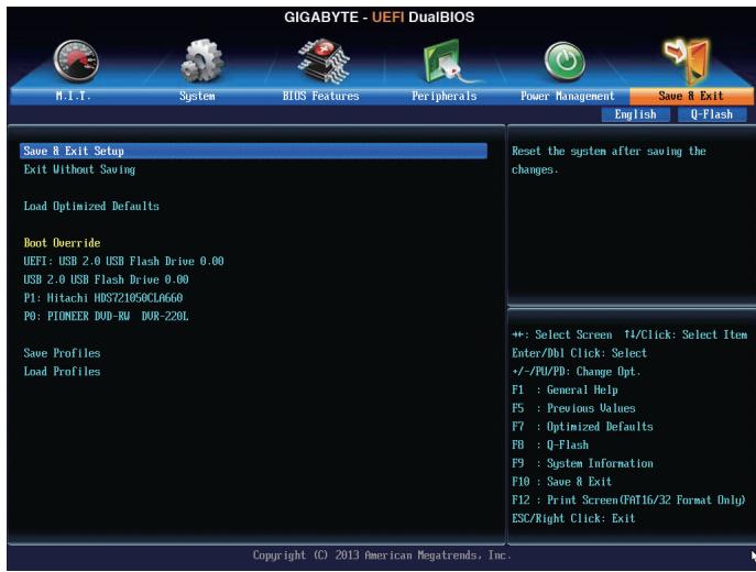
Save & Exit Setup
Press
Exit Without Saving
Press
Load Optimized Defaults
Press
Boot Override
Allows you to select a device to boot immediately. Press
Save Profiles
This function allows you to save the current BIOS settings to a profile. You can create up to 8 profiles and save as Setup Profile 1~ Setup Profile 8. Press
Load Profiles
If your system becomes unstable and you have loaded the BIOS default settings, you can use this function to load the BIOS settings from a profile created before, without the hassles of reconfiguring the BIOS settings. First select the profile you wish to load and then press
Chapter 3 Drivers Installation
RAID Levels
| RAID 0 | RAID 1 | RAID 5 | RAID 10 | |
| Minimum Number of Hard Drives | ≥2 | 2 | ≥3 | ≥4 |
| Array Capacity | Number of hard drives * Size of the smallest drive | Size of the smallest drive | (Number of hard drives -1) * Size of the smallest drive | (Number of hard drives/2) * Size of the smallest drive |
| Fault Tolerance | No | Yes | Yes | Yes |
To configure SATA hard drive(s), follow the steps below:
A. Install SATA hard drive(s) in your computer.
B. Configure SATA controller mode in BIOS Setup.
C. Configure a RAID array in RAID BIOS (Note 1)
D. Install the SATA RAID/AHCI driver and operating system (Note 2)
Before you begin
- At least two SATA hard drives (to ensure optimal performance, it is recommended that you use two hard drives with identical model and capacity). If you do not want to create RAID, you may prepare only one hard drive.
- Windows 8/7/XP setup disk.
- Motherboard driver disk.
- A USB flash drive.
- A USB floppy disk drive (needed during Windows XP installation).
- An empty formatted floppy disk (needed during Windows XP installation).
3-1 Configuring SATA Controllers
A. Installing SATA hard drive(s) in your computer
Attach one end of the SATA signal cable to the rear of the SATA hard drive and the other end to available SATA port on the motherboard. Then connect the power connector from your power supply to the hard drive.
(Note 1) Skip this step if you do not want to create RAID array on the SATA controller.
(Note 2) Required when the SATA controller is set to AHCI or RAID mode.
B. Configuring SATA controller mode in BIOS Setup
Make sure to configure the SATA controller mode correctly in system BIOS Setup.
Step 1:
Turn on your computer and press
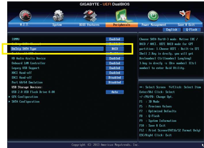
Figure 1
Step 2:
If you want to configure UEFI RAID, follow the steps in "C-1." To enter the legacy RAID ROM, save the settings and exit BIOS Setup. Refer to "C-2" for more information.

The BIOS Setup menus described in this section may differ from the exact settings for your motherboard. The actual BIOS Setup menu options you will see shall depend on the motherboard you have and the BIOS version.
C-1.UEFI RAID Configuration
This mode supports Windows 8 64-bit installation only.
Step 1:
In BIOS Setup, go to BIOS Features and set OS Type to Windows 8 and CSM Support to Never. (Figure 2)
Save the changes and exit BIOS Setup.
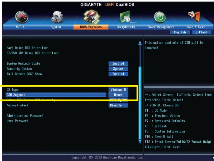
Figure 2
Step 2:
Restart your computer and press <F12> to enter the boot device configuration menu. Use the up or down arrow key to select EFI: Built-in EFI Shell. Press <Enter> to access the screen as shown in Figure 3. Follow the steps below and enter the commands to access the RAID setup utility.
- Enter drvcfg at Shell and press
:
Shell>DRVcfg
- When Drv [XX] Ctrl [XX] Lang [eng] appears, enter the following commands at Shell again:
Shell>DRVcfg-sXX XX
(XXs are the values shown in the brackets after Drv and Ctrl above, which may vary by hard drives.)
Then press
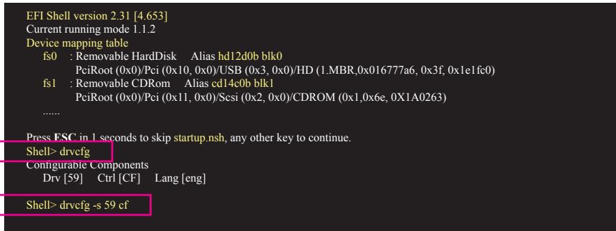
Figure 3
Step 3:
The Main Menu is the first screen when you enter the BIOS RAID Setup utility. Use the up or down arrow key to select Logical Drive Main Menu and press
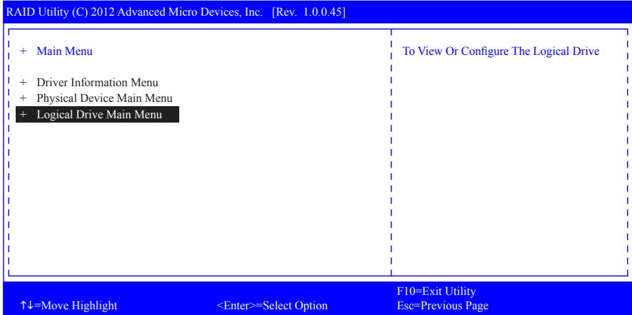
Figure 4
Step 4:
To create an array, press
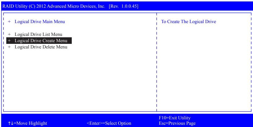
Figure 5
Step 5:
Useable hard drives are listed on the Logical Drive Create Menu. Use the up or down arrow key to select the hard drive to be included in the array and press the
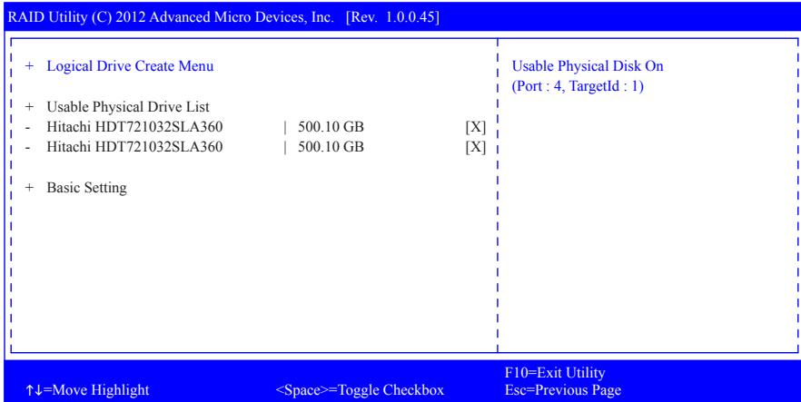
Figure 6
Step 6:
Use the up or down arrow key to move to and configure each required item in sequence.
After completing, press
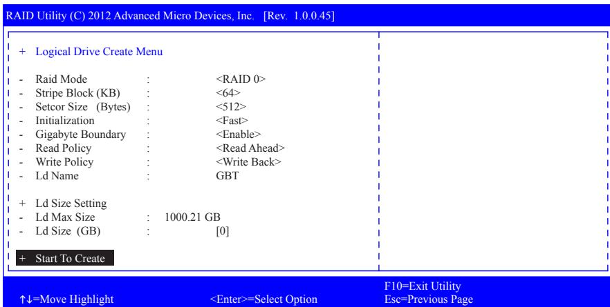
Figure 7
When completed, a message which says "Successful To Create Logical Drive" will appear. Press
Delete an Array
To delete an array, select Logical Drive Delete Menu on the Logical Drive Main Menu and press
RAID Utility (C) 2012 Advanced Micro Devices, Inc. [Rev. 1.0.0.45]
+ Logical Drive Information
LdId
- Ld Name
Raid Mode
- Ld Size
- SB Size
Sector Size
- Read Policy
Write Policy
- Ld Status
Bga State
Bga Type
2
GBT
RAID 0
999.99 GB
64
512
Read Ahead
Write Bact
Functional
None
None
- Logical Drive Member List
- Hitachi HDT721032SLA360
- Hitachi HDT721032SLA360
500.40 GB
500.40 GB
+ Start To Delete
F10=Exit Utility
Esc=Previous Page
Figure 8
C-2. Configuring Legacy RAID ROM
Enter the legacy RAID BIOS setup utility to configure a RAID array. Skip this step and proceed with the installation of Windows operating system for a non-RAID configuration.
Step 1:
After the POST memory test begins and before the operating system boot begins, look for a message which says "Press
RAID Option ROM Version 3.3.1540.17
(c) 2011 Advanced Micro Devices, Inc. All rights reserved.
No Array is defined.
Press <Ctrl-F> to enter RAID Option ROM Utility...
Figure 2
Step 2:
Main Menu
This is the first option screen when you enter the BIOS RAID Setup utility. (Figure 3)
To view the disk drives assigned to arrays, press <1> to enter the View Drive Assignments window.
To create an array, press <2> to enter the LD View/LD Define Menu window.
To delete an array, press <3> to enter the Delete LD Menu window.
To view controller settings, press < 4> to enter the Controller Configuration window.
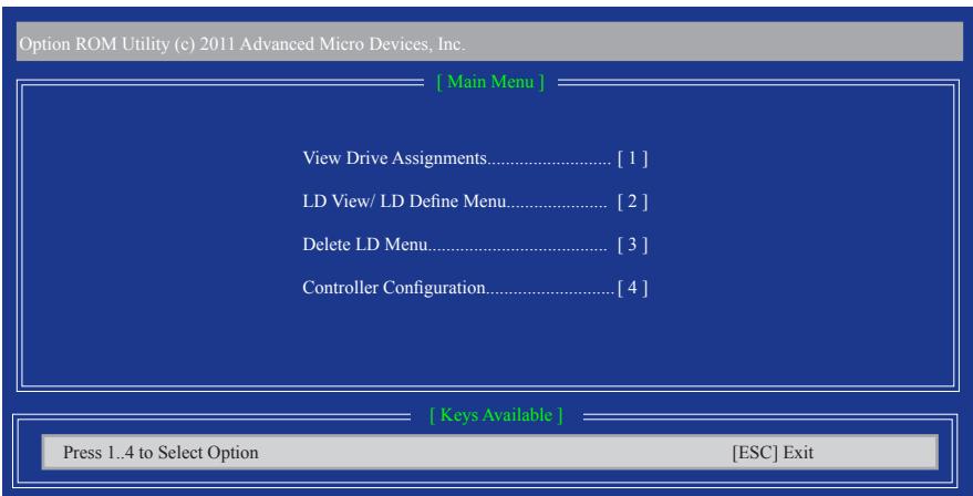
Figure 3
Create a RAID Array
To create a new array, press <2> to enter the LD View Menu window (Figure 4). To create an array, press
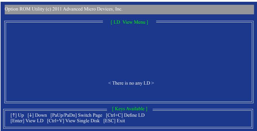
Figure 4
In the LD Define Menu, use the up or down arrow key to move to an item for further configuration (Figure 5).
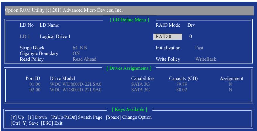
Figure 5
In the following procedure, we'll create RAID 0 as an example.
Steps:
- Under the RAID Mode section, press the
key to select RAID 0. - Set the Stripe Block size. 64 KB is the default.
- Under the Drives Assignments section, press the up or down arrow key to highlight a drive.
- Press the
key or to change the Assignment option to Y. This action adds the drive to the disk array. The Drv section will show the number of disks assigned. - Press <Ctrl> + <Y> keys to save the information. The message in Figure 6 will appear. Press <Ctrl> + <Y> to input the array name. If you do not input the array name, the default array name will be used.
Please press Ctrl-Y key to input the LD Name or press any key to exit. If you do not input any LD name, the default LD name will be used.
Figure 6
- When the next message appears, press <Ctrl> + <Y> to clear the MBR or press other keys to ignore this option. Then, the message in Figure 8 will appear.
Fast Initialization Option has been selected. It will erase the MBR data of the disk.
Figure 7
- Press <Ctrl>+ Y to set the capacity of the RAID array or press other keys to set the array to its maximum capacity.
Press Ctrl-Y to Modify Array Capacity or press any other key to use maximum capacity...
Figure 8
- After the creation is complete, the screen will return to LD View Menu where you will see the newly-created array.
- Press
to return to Main Menu and press again if you want to exit the RAID BIOS utility.
View Drive Assignments
The View Drive Assignments option in the Main Menu displays whether the attached hard drives are assigned to a disk array or are unassigned. Under the Assignment column, drives are labeled with their assigned disk array or shown as Free if unassigned.
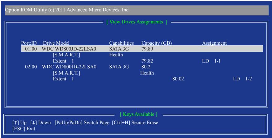
Figure 9
Delete an Array
The Delete Array menu option allows for deletion of disk array assignments.

Deleting an existing disk array could result in loss of data. Record all array information including the array type, the disk members, and stripe block size in case you wish to undo a deletion.
- To delete an array, press <3> in the Main Menu to enter the Delete LD Menu. Then highlight the array you wish to delete and press the
key or the + keys. - The View LD Definition Menu will appear (as shown in Figure 10) showing which drives are assigned to this array. Press <Ctrl>+ Y if you are sure to delete the array or other keys to abort.
- When the array is deleted, the screen will return to Delete LD Menu. Press
to return to Main Menu.
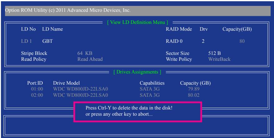
Figure 10
3-2 Installing the SATA RAID/AHCI Driver and Operating System
With the correct BIOS settings, you are ready to install the operating system.
A. Installing Windows 8/7
(The following instructions use Windows 8 as the example operating system.)
Step 1:
You need to install the SATA RAID/AHCI driver during the OS installation. Use an alternative system to copy the SATA RAID/AHCI driver from the motherboard driver disk to a USB flash drive. Copy the Hw8 folder under BootDrv in the driver disk.
Step 2:
Boot from the Windows 8 setup disk and perform standard OS installation steps. When the screen requesting you to load the driver appears, select Browse.
Step 3:
Then browse to the USB flash drive and select the location of the driver. The locations of the drivers are as follows:
RAID driver for Windows 8 32-bit: Hw8\RAID\x86
RAID driver for Windows 8 64-bit: Hw8\RAID\x64
AHCI driver for Windows 8 32-bit: Hw8\AHCI\W8
AHCI driver for Windows 8 64-bit: Hw8\AHCI\W864A
For Windows 7, browse to the Hw7 folder.
Step 4:
When a screen as shown in Figure 1 appears, select AMD AHCI Compatible RAID Controller and click Next to load the driver and continue the OS installation.
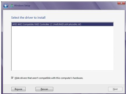
Figure 1
B. Installing Windows XP
Before installing Windows XP, connect a USB floppy disk drive to your computer first because you need to install the SATA RAID/AHCI driver from a floppy disk that contains the driver during the OS installation. Without the driver, the hard drive(s) may not be recognized during the Windows setup process. First, copy the driver from the motherboard driver disk to a floppy disk. Refer to the methods below.
Method A:
- For the AMD A85X, copy all files in the \BootDrvHxp folder to your floppy disk.
Method B:
Steps:
1: Use an alternative system and insert the motherboard driver disk.
2: From your optical drive folder, double click the Menu.exe file in the BootDrv folder. A Command Prompt window will open similar to that in Figure 2.
3: 3: Insert the blank formatted disk (if you're using a USB floppy disk drive, make sure it is designated as drive A). Select the controller driver by pressing the corresponding letter from the menu and press
Your system will then automatically copy the driver files to the floppy disk. Press any key to exit when finished.
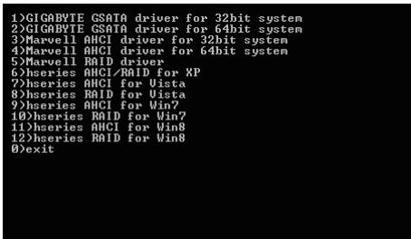
Figure 2
Refer to the following for installing the driver during the Windows setup process.
Step 1:
Restart your system to boot from the Windows XP setup disk and press <F6> as soon as you see the message "Press F6 if you need to install a 3rd party SCSI or RAID driver." A screen will then appear asking you to specify an additional SCSI adapter. Press <S> .
Step 2:
Insert the floppy disk containing the SATA RAID/AHCI driver and press
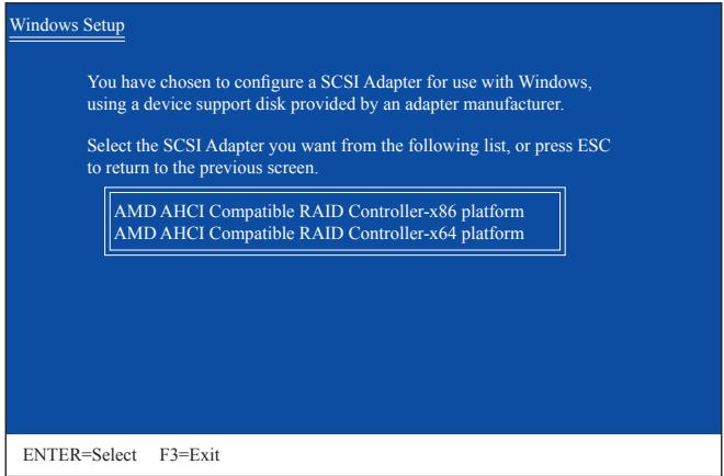
Figure 3
Step 3:
On the next screen, press
Rebuilding an Array:
Rebuilding is the process of restoring data to a hard drive from other drives in the array. Rebuilding applies only to fault-tolerant arrays such as RAID 1, RAID 5, and RAID 10 arrays. To replace the old drive, make sure to use a new drive of equal or greater capacity. The procedures below assume a new drive is added to replace a failed drive to rebuild a RAID 1 array.
While in the operating system, make sure the Chipset driver has been installed from the motherboard driver disk. Then install the AMD RAID Utility (go to Application Software\Install Application Software and select AMD RAID Utility to install). Then launch the AMD RAIDXpert from All Programs in the Start Menu.
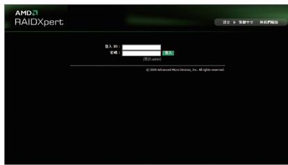
Step 1:
Enter the login ID and password (default: "admin"), and then click Sign in to launch AMD RAIDXpert.
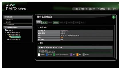
Step 2:
Select the RAID array to be rebuilt under Logical Drive View and click the Rebuild tab in the Logical Drive Information pane.
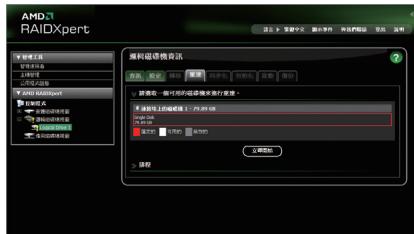
Step 3:
Select one available drive and click Start Now to start the rebuilding process.
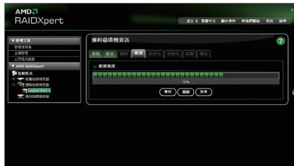
Step 4:
The rebuilding progress is displayed on the screen and you can select Pause/Resume/Abort during the rebuilding process.
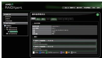
Step 5:
When done, the array's status on the Information page in the Logical Drive Information pane will display as Functional.
Chapter 4 Drivers Installation

- Before installing the drivers, first install the operating system.
After installing the operating system, insert the motherboard driver disk into your optical drive. The driver Autorun screen is automatically displayed which looks like that shown in the screen shot below. (If the driver Autorun screen does not appear automatically, go to My Computer, double-click the optical drive and execute the Run.exe program.)
4-1 Installing Chipset Drivers

Now Loading Please wait...
After inserting the driver disk, "Xpress Install" will automatically scan your system and then list all the drivers that are recommended to install. You can click the Install All button and "Xpress Install" will install all the recommended drivers. Or click Install Single Items to manually select the drivers you wish to install.
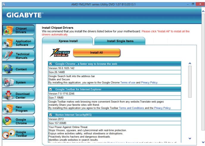

- Please ignore the popup dialog box(es) (e.g. the Found New Hardware Wizard) displayed when "Xpress Install" is installing the drivers. Failure to do so may affect the driver installation.
- Some device drivers will restart your system automatically during the driver installation. After the system restart, "Xpress Install" will continue to install other drivers.
- After "Xpress Install" installs all of the drivers, a dialog box will appear asking whether to install new GIGABYTE utilities. Click Yes to automatically install the utilities. Or click No if you want to manually select the utilities to install on the Application Software page later.
- For USB 2.0 driver support under the Windows XP operating system, please install the Windows XP Service Pack 1 or later. After installing the SP1 (or later), if a question mark still exists in Universal Serial Bus Controller in Device Manager, please remove the question mark (by right-clicking your mouse and select Uninstall) and restart the system. (The system will then autodetect and install the USB 2.0 driver.)
4-2 Application Software
This page displays all the utilities and applications that GIGABYTE develops and some free software. You can click the Install button on the right of an item to install it.
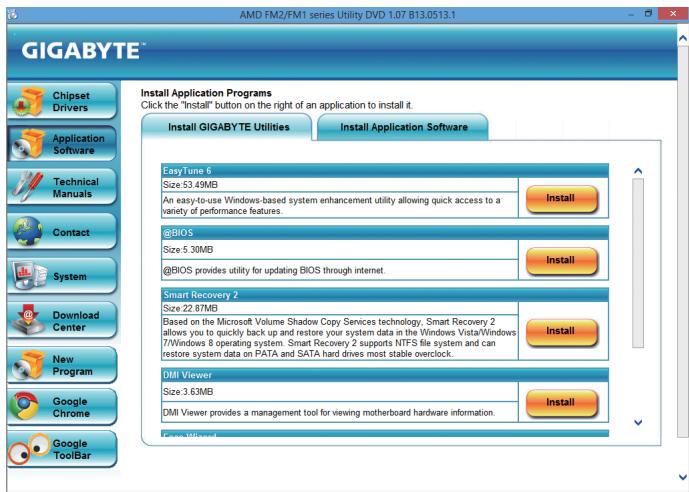
4-3 Technical Manuals
This page provides the content descriptions for this driver disk.
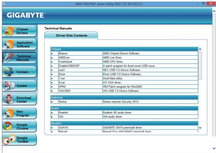
4-4 Contact
For the detailed contact information of the GIGABYTE Taiwan headquarters or worldwide branch offices, click the URL on this page to link to the GIGABYTE website.
4-5 System
This page provides the basic system information.
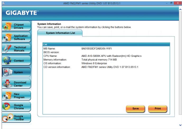
4-6 Download Center
To update the BIOS, drivers, or applications, click the Download Center button to link to the GIGABYTE website. The latest version of the BIOS, drivers, or applications will be displayed.
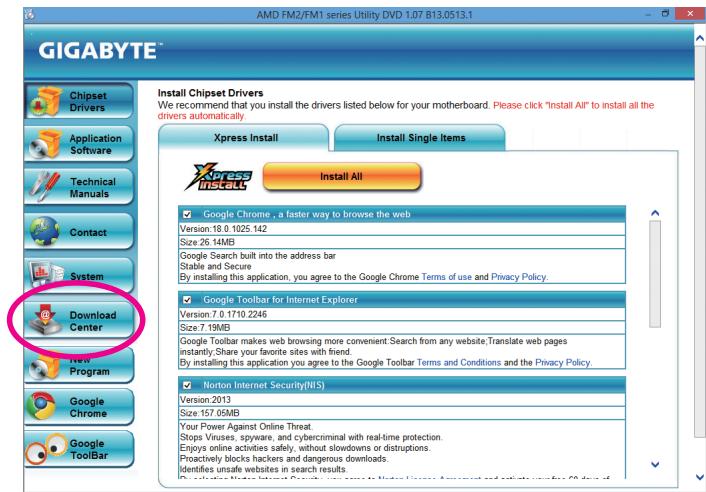
Chapter 5 Unique Features
5-1 BIOS Update Utilities
GIGABYTE motherboards provide two unique BIOS update tools, Q-Flash™ and @BIOS™. GIGABYTE Q-Flash and @BIOS are easy-to-use and allow you to update the BIOS without the need to enter MS-DOS mode. Additionally, this motherboard features the DualBIOS™ design, which enhances protection for the safety and stability of your computer by adding one more physical BIOS chip.
What is DualBIOS?
Motherboards that support DualBIOS have two BIOS onboard, a main BIOS and a backup BIOS. Normally, the system works on the main BIOS. However, if the main BIOS is corrupted or damaged, the backup BIOS will take over on the next system boot and copy the BIOS file to the main BIOS to ensure normal system operation. For the sake of system safety, users cannot update the backup BIOS manually.
What is Q-Flash?
With Q-Flash you can update the system BIOS without having to enter operating systems like MS-DOS or Window first. Embedded in the BIOS, the Q-Flash tool frees you from the hassles of going through complicated BIOS flashing process.
What is @BIOS™?
@BIOS allows you to update the system BIOS while in the Windows environment. @BIOS will download the latest BIOS file from the nearest @BIOS server site and update the BIOS.
5-1-1 Updating the BIOS with the Q-Flash Utility
A. Before You Begin
- From GIGABYTE's website, download the latest compressed BIOS update file that matches your motherboard model.
- Extract the file and save the new BIOS file (e.g. 85XNWIFI.F1) to your USB flash drive, or hard drive. Note: The USB flash drive or hard drive must use FAT32/16/12 file system.
- Restart the system. During the POST, press the
key to enter Q-Flash. Note: You can access Q-Flash by either pressing the key during the POST or pressing the key in BIOS Setup. However, if the BIOS update file is saved to a hard drive in RAID/AHCI mode or a hard drive attached to an independent SATA controller, use the key during the POST to access Q-Flash.

Because BIOS flashing is potentially risky, please do it with caution. Inadequate BIOS flashing may result in system malfunction.
B. Updating the BIOS
In the main menu of Q-Flash, use the keyboard or mouse to select an item to execute. When updating the BIOS, choose the location where the BIOS file is saved. The following procedure assumes that you save the BIOS file to a USB flash drive.
Step 1:
- Insert the USB flash drive containing the BIOS file into the computer. In the main menu of Q-Flash, select Update BIOS From Drive.

The Save Main BIOS to Drive option allows you to save the current BIOS file.
Q-Flash only supports USB flash drive or hard drives using FAT32/16/12 file system.
- If the BIOS update file is saved to a hard drive in RAID/AHCI mode or a hard drive attached to an independent SATA controller, use the
2. Select USB Flash Drive.
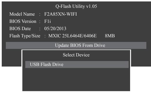
3. Select the BIOS update file.

Make sure the BIOS update file matches your motherboard model.
Step 2:
The process of the system reading the BIOS file from the USB flash drive is displayed on the screen. When the message "Are you sure to update BIOS?" appears, select Yes to begin the BIOS update. The monitor will display the update process.

- Do not turn off or restart the system when the system is reading/updating the BIOS.
- Do not remove the USB flash drive or hard drive when the system is updating the BIOS.
Step 3:
When the update process is complete, select Reboot to reboot the system.
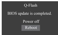
Step 4:
During the POST, press
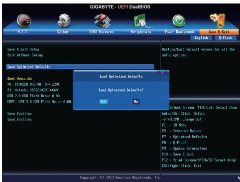
Select Yes to load BIOS defaults
Step 5:
Select Save & Exit Setup and press
5-1-2 Updating the BIOS with the @BIOS Utility
A. Before You Begin
- In Windows, close all applications and TSR (Terminate and Stay Resident) programs. This helps prevent unexpected failures when performing a BIOS update.
- During the BIOS update process, ensure the Internet connection is stable and do NOT interrupt the Internet connection (for example, avoid a power loss or switching off the Internet). Failure to do so may result in a corrupted BIOS or a system that is unable to start.
- Do not use the G.O.M. (GIGABYTE Online Management) function when using @BIOS.
- GIGABYTE product warranty does not cover any BIOS damage or system failure resulting from an inadequate BIOS flashing.
B. Using @BIOS
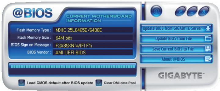
- Update BIOS from GIGANTE Server Update the BIOS Using the Internet Update Function:
Click Update BIOS from GIGABYTE Server, select the @BIOS server site closest to your location and then download the BIOS file that matches your motherboard model. Follow the on-screen instructions to complete.

If the BIOS update file for your motherboard is not present on the @BIOS server site, please manually download the BIOS update file from GIGABYTE's website and follow the instructions in "Update the BIOS without Using the Internet Update Function" below.
- Update BIOS from The Update the BIOS without Using the Internet Update Function:
Click Update BIOS from File, then select the location where you save the BIOS update file obtained from the Internet or through other source. Follow the on-screen instructions to complete.
- Save Current BIOS to File Save the Current BIOS File:
Click Save Current BIOS to File to save the current BIOS file.
- Load CMOS default after BIOS update Load BIOS Defaults after BIOS Update:
Select the Load CMOS default after BIOS update check box and then the system will automatically load BIOS defaults after BIOS update and after the system restarts.
C. After Updating the BIOS
Restart your system after updating the BIOS.

Make sure that the BIOS file to be flashed matches your motherboard model. Updating the BIOS with an incorrect BIOS file could cause your system not to boot.
5-2 EasyTune 6
GIGABYTE's EasyTune 6 is a simple and easy-to-use interface that allows users to fine-tune their system settings or do overclock/overvoltage in Windows environment. The user-friendly EasyTune 6 interface also includes tabbed pages for CPU and memory information, letting users read their system-related information without the need to install additional software.
The EasyTune 6 Interface
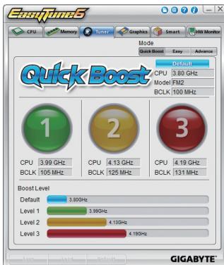
Tabs Information
| Tab | Description |
| CPU | The CPU tab provides information on the installed CPU and motherboard. |
| Memory | The Memory tab provides information on the installed memory module(s). You can select memory module on a specific slot to see its information. |
| Tuner | The Tuner tab allows you to change memory settings and voltages. ·Quick Boost mode provides you with 3 levels of CPU frequency/base clock to choose to achieve desired system performance. After making changes in Quick Boost mode or clicking Default to restore to default values, be sure to restart your system for these changes to take effect. ·Easy mode provides information on CPU/memory. ·Advanced mode allows you to individually change system clock settings and voltages settings using the sliders. ·Save allows you to save the current settings to a new profile (.txt file). ·Load allows you to load previous settings from a profile. After making changes in Easy mode/Advanced mode, be sure to click Set for these changes to take effect or click Default to restore to default values. |
| Graphics | The Graphics tab allows you to change the core clock and memory clock for your AMD or NVIDIA graphics card. |
| Smart | The Smart tab allows you to specify a Smart Fan mode. Smart Fan Advanced mode allows the fan speed to be changed linearly based on the temperature thresholds you set. |
| HW Monitor | The HW Monitor tab allows you to monitor hardware temperature, voltage and fan speed and set temperature/fan speed alarm. You can choose the alert sound from the buzzer or use your own sound file (.wav file). |

Available functions in EasyTune 6 may differ by motherboard model. Grayed-out area(s) indicates that the item is not configurable or the function is not supported.

Incorrectly doing overclock/overvoltage may result in damage to the hardware components such as CPU, chipset, and memory and reduce the useful life of these components. Before you do the overclock/overvoltage, make sure that you fully know each function of EasyTune 6, or system instability or other unexpected results may occur.
5-3 Smart Recovery 2
Smart Recovery 2 allows you to back up a partition as an image file every hour. You can use these images to restore your system or files when needed.
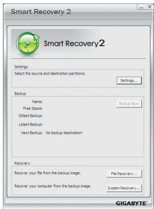
The Smart Recovery 2 main menu:
| Button | Description |
| Settings | Allows you to select the source and destination partition |
| Backup Now | Allows you to perform the backup immediately |
| File Recovery... | Allows you to recover your files from the backup image |
| System Recovery... | Allows you to recover your system from the backup image |

Supported operating systems: Windows 8, 7 and Vista.
- Smart Recovery 2 only supports NTFS file system.
- You need to select the destination partition in Settings the first time you use Smart Recovery 2.
- The Backup Now button will be available only after you log in Windows for ten minutes.
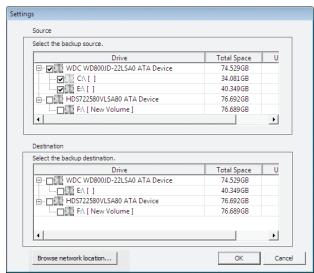
Creating a backup:
Click the Settings button on the main menu. In the Settings dialog box, select the source partition and destination partition and click OK. The initial backup will start after 10 minutes and regular backup will be performed hourly. Note: By default, all partitions on the system drive are selected as the backup source. The backup destination cannot be on the same partition as the backup source.
Saving the the backup to a network location:
If you want to save the backup to a network location, select Browse network location. Make sure your computer and the computer where you want to save the backup are in the same domain. Choose the network location where you want to store the backup and enter the user name and password. Follow the on-screen instructions to complete.
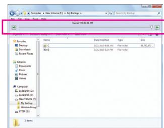
Recovering a file:
Click the File Recovery button on the main menu. Use the time slider on the top of the popped out window to select a previous backup time. The right pane will display the backed-up partitions in the backup destination (in the My Backup folder). Browse to the file you want and copy it.
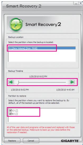
Recovering your system with Smart Recovery 2 (Windows 8/7 only): Steps:
- Click the File Recovery button on the main menu.
- Select the location where your backup is saved.
- Use the time slider to select a time point.
- Select a partition backup created on the selected time point and click Restore.
- Confirm whether to restart your system to proceed with the restore immediately or later. Once you respond "Yes" the system will restart to the Windows recovery environment. Follow the onscreen instructions to restore your system.

- For Windows Vista, refer to the steps below to use the original Windows installation disk for system recovery.
- All of your files and programs will be deleted and replaced with those on the selected backup. If needed, be sure to make a copy of your data before the restore.
Recovering your system using the original Windows installation disk:
In case Windows or your hard drive has serious errors, use the original Windows installation disk for system recovery.
Steps:
- Restart your computer to boot from the original Windows installation disk.
- When the Windows installation screen appears, select your language and click Next.
- Select Repair your computer.
- Select Restore your computer using a system image that you created earlier and then click Next.
- Select the backup you want to use and then follow the on-screen instructions to complete.

For further instructions, refer to the Help file of Smart Recovery 2.
5-4 Using the Wi-Fi/Bluetooth Utilities
5-4-1 Using the Wi-Fi Share Utility
Install the drivers and utilities from the included wireless module driver disk. The Wi-Fi Share utility allows you to configure how your Wi-Fi/Bluetooth card will act. First it can turn your computer into a virtual wireless access point (Hotspot), which allows WiFi-capable computers or mobile devices to access the Internet through the virtual wireless access point. Second, it can be configured to let your computer share data to another computer by simply dragging the data from your computer to the target computer (File Transfer). Third, it surely can be
used as a normal wireless LAN card (WiFi).

The Wi-Fi Share utility is supported in Windows 8/7 only.
To use Wi-Fi Share for the first time, click the Wi-Fi Share Manager icon on the Start screen (Windows 8) or launch it from StartAll Applications (Windows 7). Then right-click the Wi-Fi Share icon in the notification area to display configuration options.

Option Descriptions
| Option | Description |
| Manage Wi-Fi Share | Opens the Wi-Fi Share Manager |
| Local Share Directory | Goes to the directory where shared files are located (File Transfer) |
| Mode Choice | Selects which mode to operate |
| Setting | Configures further settings depending on the mode selected |
| Reset Router | Reset the Wi-Fi Share utility |
| Live Update | Updates Wi-Fi Share online |
| Help | Displays the help file |
| About | Displays the Wi-Fi Share version |
| Exit | Exits Wi-Fi Share |
Mode Selection
Wi-Fi Share provides three modes for users to select as follows:
A. Hotspot
The Hotspot turns your computer into a virtual wireless access point (WAP). Refer to the steps below for detailed configurations.
Configuring your computer:
Step 1:
Right-click the Wi-Fi Share icon in the notification area and select Mode Choice > Hotspot to turn your computer into a virtual wireless AP. Then select Setting.
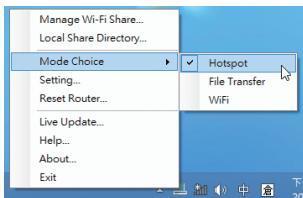
Step 2:
When the Wi-Fi Share Settings dialog box appears, select a currently running network connection you want to share from the Share Connection list. Then click Save. The Password represents the network security key which is required when other computer wants to access the Internet through the virtual wireless AP. You can keep the default password or create your own one.
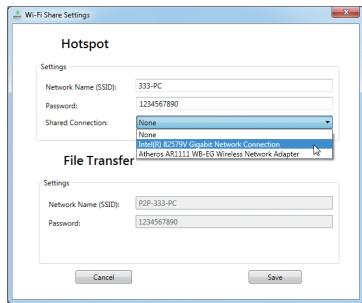
Configuring the computer that wants to access the Internet through the virtual wireless AP:
Step 1:
Left-click the Internet Access icon in the notification area. When the Currently connected to list appears, select the virtual wireless AP you want to connect to and click Connect.
Step 2:
When the Connect to a Network dialog box appears, enter the security key of the network connection the virtual wireless AP is sharing and click OK.
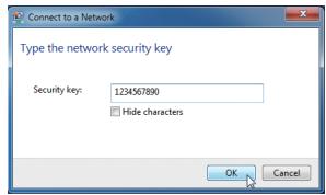
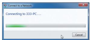
Step 3:
After the connection, the Currently connected to list shows that this computer is currently using the network connection shared by the virtual wireless AP.
B. File Transfer
The File Transfer allows two computers with File Transfer enabled to share files to each other. Note: Be sure to turn off the firewall on both computers before using File Transfer.
Step 1:
Make sure the two computers are installed with the Wi-Fi Share utility and have File Transfer enabled. On the desktop of the source computer, right-click the Wi-Fi Share icon in the notification area and select Mode Choice > File Transfer. Then select Manage Wi-Fi Share to open the Wi-Fi Share Manager.
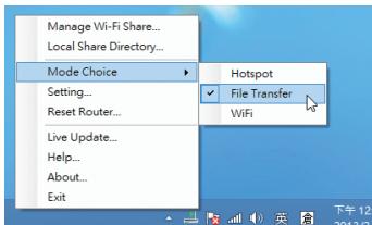
Step 2:
The Wi-Fi Share Manager will display the other computer with File Transfer enabled (the target computer).
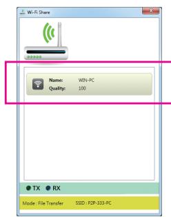
Step 3:
Go the directory where the file/folder that you want to share is located. Drag the file/folder to the target computer displayed on the Wi-Fi Share Manager.
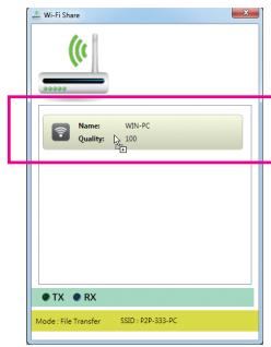
Step 4:
When asked whether to send the file/folder to the target computer, click Yes. The TX light will be on when the file/data is being sent.
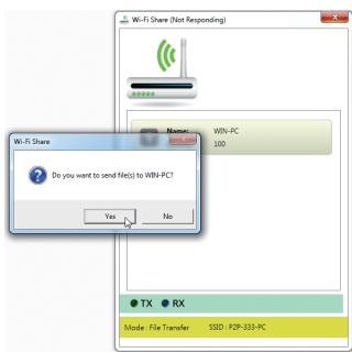
Step 5:
The confirmation message will also appear on the target computer, asking whether to accept the file/folder from the source computer. Click Yes to confirm. You must respond in 15 seconds. The RX light will be on when the file/data is being received.
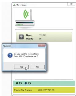
Step 6:
The data will be automatically stored to a folder in the My Documents\AirFileDownloads directory in the target computer, which is named according to the receiving time. To directly access this directory later, you can also right-click the Wi-Fi Share icon in the notification area and select Local Shared Directory.
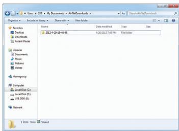
C.WiFi
In this mode, the Wi-Fi/Bluetooth card is set as a normal wireless LAN card and needs to connect to a wireless access point to get Internet connection.
5-4-2 Using the Cloud Station Utility
The Cloud Station utility allows GIGABYTE's iOS APPs to communicate, share resources, and control your desktop PC systems. Two GIGABYTE's unique iOS APPs are available now: EasyTune Touch and PictureView, both of which can be downloaded from the Apple store for free.
System Requirements:
Windows 8/7
i-Tunes
iPhone 5, iPhone 4, iPhone 3, and iPad series
(iPhone 3 and iPad series only support Wi-Fi connection)
EasyTune Touch:

EasyTune Touch is a simple and easy-to-use application that allows users to remotely control their system through Apple devices, including iPhone and iPad. Detailed functions are as follows:
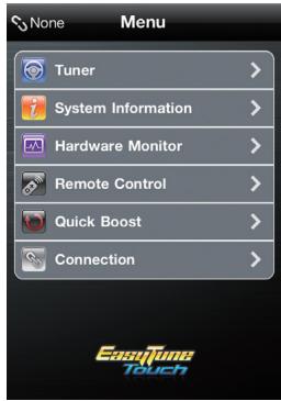
Option Descriptions
| Option | Description |
| Tuner | Allows you to change CPU/memory frequency and voltage settings. |
| System Information | Displays the system information, including the CPU, motherboard, and memory. |
| Hardware Monitor | Allows you to monitor hardware temperature, voltage, and fan speed. |
| Remote Control | Allows you to reboot or shut down your computer. |
| Quick Boost | Provides you with 3 levels of automatic system tuning. |
| Connection | Selects how iPhone/iPad will connect to your computer. |
PictureView:

The PictureView application is designed to allow users to quickly and effortlessly share photographs from their iOS device directly to their computer. By simply selecting a photo from the iOS device's picture library, the user will then be instantly able to see it on their PC desktop.
Using the Cloud Station:
After the Cloud Station utility is installed, the Cloud Station icon will appear in the notification area. You can right-click this icon and select Always run on next reboot to launch this utility each time you reboot the computer. To use EasyTune Touch and PictureView on your iPhone/ iPad, you must launch the Cloud Station utility on your computer first.
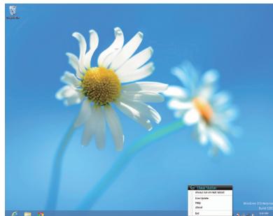
Three ways of connection:
Before using EasyTune Touch and PictureView, use one of the three ways below to connect your Apple devices to the target computer: Wi-Fi, Bluetooth, and USB connections. iPhone 3 and iPad series only support Wi-Fi connection and iPhone 4/5 series supports all of the three connections. Below we use iPhone 4 as the demonstration Apple device. (Make sure i-Tunes is installed first.)
A. Wi-Fi Connection:
Make sure your iPhone and computer are using the same network connection.
Step 1:
Make sure your computer is connected to a network connection.
Step 2:
On your iPhone, go to Settings>Wi-Fi and turn on the Wi-Fi function. Then choose the same network connection that your computer is currently using.
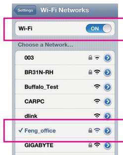
Using EasyTune Touch
Step 1:
Go to the main menu of the EasyTune Touch application on your iPhone. Select Connection.
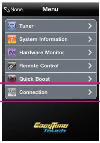
Step 2:
On the Connection page, select Wifi. iPhone will begin to search for the computer using the same network connection. When the computer is displayed, select it. Then return to the main menu of the EasyTune Touch application. Now you are able to use the EasyTune Touch functions to remotely control the target computer via the iPhone or check hardware information.
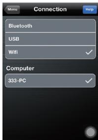
Using PictureView
Step 1:
Go to the main screen of the PictureView application. In the photo gallery, select Connect.
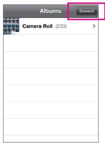
Step 2:
On the Connection page, select Wifi. iPhone will begin to search for the computer using the same network connection. When the computer is displayed, select it. Then return to photo gallery.
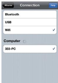
Step 3:
Click the photo you want to share and your photo will be shown instantly on the desktop of the target computer.
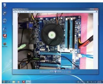
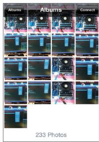
B. BlueTooth Connection:
Step 1:
On your iPhone, go to Settings > Personal Hotspot and turn on this function. Then go to Settings > General > Bluetooth to turn Bluetooth on.
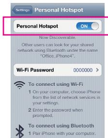
Step 2:
Now you have to pair the iPhone with your computer. In the operating system of your computer, go to Control Panel > Devices and Printers. Select Add a device. Your computer will look for Bluetooth devices and display them on the screen. When the iPhone is displayed, select it and click Next.
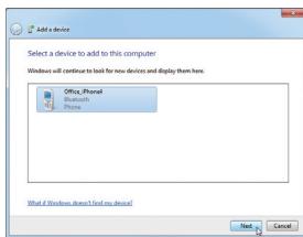
Step 3:
A pairing code will appear on the screen. You iPhone will display a message with the pairing code for you to confirm as well (refer to the next screenshot). Click Next.
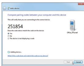
Step 4:
When the iPhone displays the pairing code, press Pair to confirm. After the pairing is successful, your iPhone will show that it has been connected to your computer.
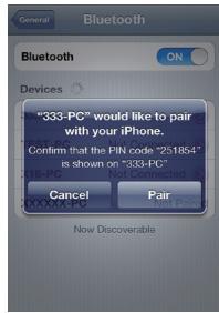
Step 5:
Your computer will show that the iPhone has been added to your computer successfully. Click Close to return to the Control Panel > Devices and Printers window.
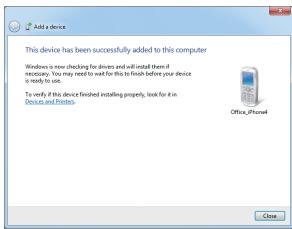
Step 6:
Look for your iPhone device, right-click it, and select Connect using > Access Point to complete the configuration.
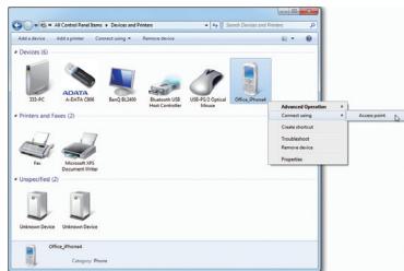
Now, you are ready to use EasyTune Touch or PictureView. Refer to the instructions on configuration Wi-Fi connection and select Bluetooth connection.
C. USB Connection:
Step 1:
On your iPhone, go to Settings > Personal Hotspot and turn on this function.
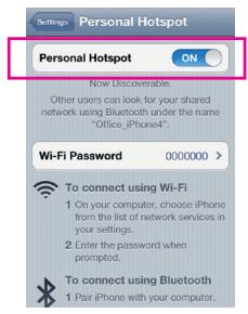
Step 2:
Connect your iPhone to your computer using the iPhone USB cable.
Step 3:
After the iPhone is connected to your computer, go to Control Panel > Network and Sharing Center > Change adapter settings. Make sure Apple Mobile Device Ethernet is present. If not, re-check the connection.
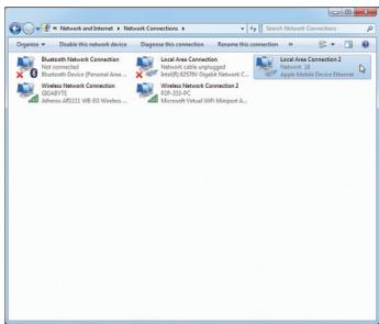
Now, you are ready to use EasyTune Touch or PictureView. Refer to the instructions on configuration Wi-Fi connection and select USB connection.
Chapter 6 Appendix
6-1 Configuring Audio Input and Output
6-1-1 Configuring 2/4/5.1/7.1-Channel Audio
The motherboard provides five audio jacks on the back panel which support 2/4/5.1/7.1-channel (Note) audio. The picture to the right shows the default audio jack assignments.
The integrated HD (High Definition) audio provides jack retasking capability that allows the user to change the function for each jack through the audio driver.
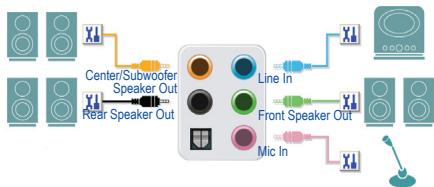
(Supported functions for each jack may vary based on hardware specification.)

- To install a microphone, connect your microphone to the Mic in jack and manually configure the jack for microphone functionality.
- If you install a Side Speaker, you need to retask other audio jack to be Side Speaker out.
- Audio signals will be present on both of the front and back panel audio connections simultaneously. If you want to mute the back panel audio (only supported when using an HD front panel audio module), refer to instructions on the next page.
High Definition Audio (HD Audio)
HD Audio includes multiple high quality digital-to-analog converters (DACs) and features multistreaming capabilities that allow multiple audio streams (in and out) to be simultaneously processed. For example, users can listen to MP3 music, have an Internet chat, make a telephone call over the Internet, and etc. all at the same time.
A. Configuring Speakers
(The following instructions use Windows 8 as the example operating system.)
Step 1:
After installing the audio driver, restart your computer.
Then switch to Windows desktop mode. The HD Audio
Manager icon will appear in the notification area.
Double-click the icon to access the HD Audio Manager.
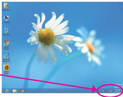
(Note) 2/4/5.1/7.1-Channel Audio Configurations:
Refer to the following for multi-channel speaker configurations.
2-channel audio: Headphone or Line out.
4-channel audio: Front speaker out and Rear speaker out.
- 5.1-channel audio: Front speaker out, Rear speaker out, and Center/Subwoofer speaker out.
- 7.1-channel audio: Front speaker out, Rear speaker out, Center/Subwoofer speaker out, and Side speaker out.
Step 2:
Connect an audio device to an audio jack. The The current connected device is dialog box appears. Select the device according to the type of device you connect. Then click OK.
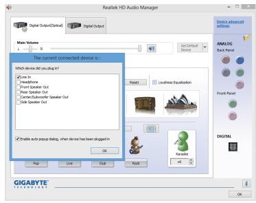
Step 3:
On the Speakers screen, click the Speaker Configuration tab. In the Speaker Configuration list, select Stereo, Quadraphonic, 5.1 Speaker, or 7.1 Speaker according to the type of speaker configuration you wish to set up. Then the speaker setup is completed.
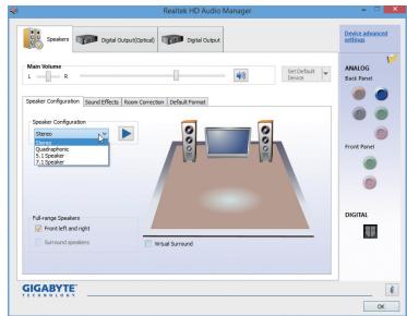
B. Configuring Sound Effect
You may configure an audio environment on the Sound Effects tab.
C. Activating an AC'97 Front Panel Audio Module
If your chassis provides an AC'97 front panel audio module, to activate the AC'97 functionality, click the tool icon on the Speaker Configuration tab. On the Connector Settings dialog box, select the Disable front panel jack detection check box. Click OK to complete.
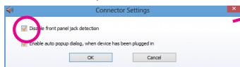
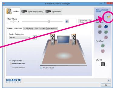
D. Muting the Back Panel Audio (For HD Audio Only)
Click Device advanced settings on the top right corner on the Speaker Configuration tab to open the Device advanced settings dialog box. Select the Mute the rear output device, when a front headphone plugged in check box. Click OK to complete.
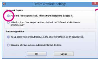
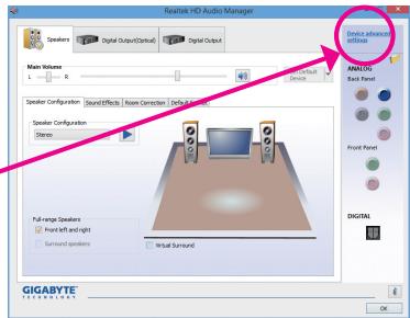
6-1-2 Configuring S/PDIF Out
The S/PDIF Out jack can transmit audio signals to an external decoder for decoding to get the best audio quality.
1. Connecting a S/PDIF Out Cable:
Connect a S/PDIF optical cable to the corresponding S/PDIF out connector as shown below and an external decoder for transmitting the S/PDIF digital audio signals.
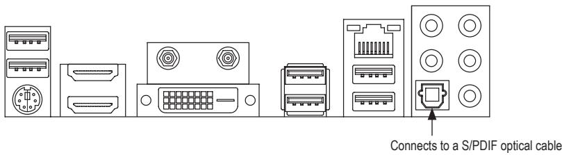
2. Configuring S/PDIF Out:
On the Digital Output(Optical) screen (Note), click the Default Format tab and then select the sample rate and bit depth. Click OK to complete.
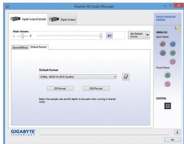
(Note) Enter the Digital Output(Optical) screen to configure further settings if you use the S/PDIF Out connector(s) on the back panel for digital audio output or enter the Digital Output screen if you use the internal S/PDIF Out connector (SPDIF_O) for digital audio output.
6-1-3 Configuring Microphone Recording
Step 1:
After installing the audio driver, the HD Audio Manager icon will appear in the notification area. Double-click the icon to access the HD Audio Manager.

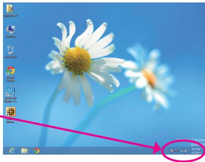
Step 2:
Connect your microphone to the Mic in jack (pink) on the back panel or the Mic in jack (pink) on the front panel. Note: The microphone functions on the front panel and back panel cannot be used at the same time.
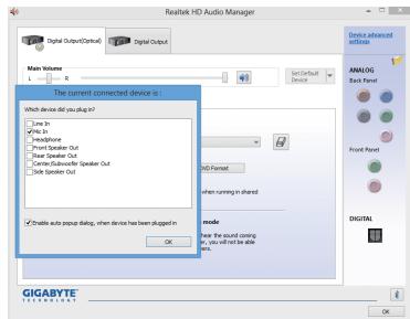
Step 3:
Go to the Microphone screen. Do not mute the recording volume, or you'll not be able to record the sound. To hear the sound being recorded during the recording process, do not mute the playback volume. It is recommended that you set the volumes at a middle level.
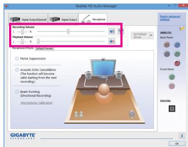
Step 4:
To raise the recording and playback volume for the microphone, click the Microphone Boost icon on the right of the Recording Volume slider and set the Microphone Boost level.
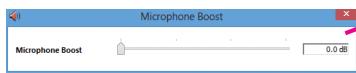
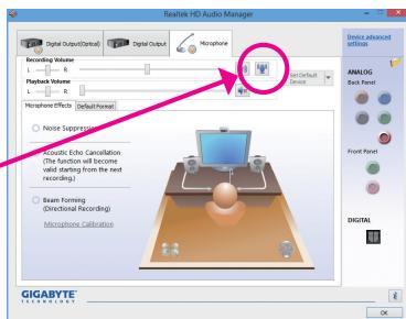
Step 5:
To open the Sound Recorder, move the mouse cursor to the bottom left corner of the screen, click the Start icon to switch to the Start screen (or press the Windows button on the keyboard). Right-click on the screen and click the All apps icon on the bottom right corner of the screen to access the Apps screen.
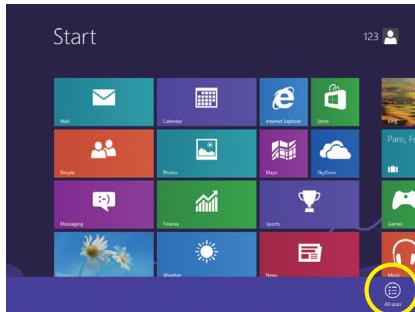
Step 6:
On this screen, click Sound Recorder for audio recording.
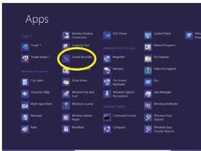
* Enabling Stereo Mix
If the HD Audio Manager does not display the recording device you wish to use, refer to the steps below. The following steps explain how to enable Stereo Mix (which may be needed when you want to record sound from your computer).
Step 1:
Locate the icon in the notification area and right-click on this icon. Select Recording devices.
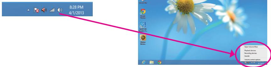
Step 2:
On the Recording tab, right-click on an empty space and select Show Disabled Devices.
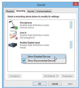
Step 3:
When the Stereo Mix item appears, right-click on this item and select Enable. Then set it as the default device.
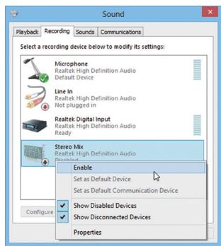
Step 4:
Now you can access the HD Audio Manager to configure Stereo Mix and use Sound Recorder to record the sound.
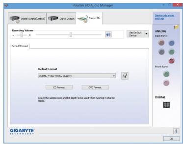
6-1-4 Using the Sound Recorder
A. Recording Sound
- Make sure you have connected the sound input device (e.g. microphone) to the computer.
- To record the audio, click the Start Recording button
- To stop recording audio, click the Stop Recording button Stop Recording
Be sure to save the recorded audio file upon completion.
B. Playing the Recorded Sound
You can play your recording in a digital media player program that supports your audio file format.
6-2 Troubleshooting
6-2-1 Frequently Asked Questions
To read more FAQs for your motherboard, please go to the Support & Downloads\FAQ page on GIGABYTE's website.
Q: Why is the light of my keyboard/optical mouse still on after the computer shuts down?
A: Some motherboards provide a small amount of standby power after the computer shuts down and that's why the light is still on.
Q: How do I clear the CMOS values?
A: For motherboards that have a Clear CMOS button, press this button to clear the CMOS values (before doing this, please turn off the computer and unplug the power cord). For motherboards that have a Clear CMOS jumper, refer to the instructions in Chapter 1 to short the jumper to clear the CMOS values. If your board doesn't have this jumper/button, refer to the instructions on the motherboard battery in Chapter 1. You can temporarily remove the battery from the battery holder to stop supplying power to the CMOS, which will clear the CMOS values after about one minute.
Q: Why do I still get a weak sound even though I have turned my speaker to the maximum volume?
A: Make sure your speaker is equipped with an internal amplifier. If not, try a speaker with power/amplifier.
Q: Why cannot I install the onboard HD audio driver successfully? (For Windows XP only)
A: Step 1: First, make sure Service Pack 1 or Service Pack 2 has been installed (check in My Computer > Properties > General > System). If not, please update it from Microsoft's website. Then make sure the Microsoft UAA Bus Driver for High Definition Audio has been installed successfully (check in My Computer > Properties > Hardwareware > Device Manager > System Devices).
Step 2: Check if Audio Device on High Definition Audio Bus or Unknown device is present in Device Manager or Sound, video, and game controllers. If yes, please disable this device. (If not, skip this step.)
Step 3: Then go back to My Computer > Properties > Hardware > Device Manager > System devices and right-click on Microsoft UAA Bus Driver for High Definition Audio and select Disable and Uninstall
Step 4: In Device Manager, right-click on the computer name and select Scan for hardware changes. When the Add New Hardware Wizard appears, click Cancel. Then install the onboard HD audio driver from the motherboard driver disk or download the audio driver from GIGARYTF's website to install.
For more details, go to the Support & Downloads\FAQ page on our website and search for "onboard HD audio driver."
6-2-2 Troubleshooting Procedure
If you encounter any troubles during system startup, follow the troubleshooting procedure below to solve the problem.
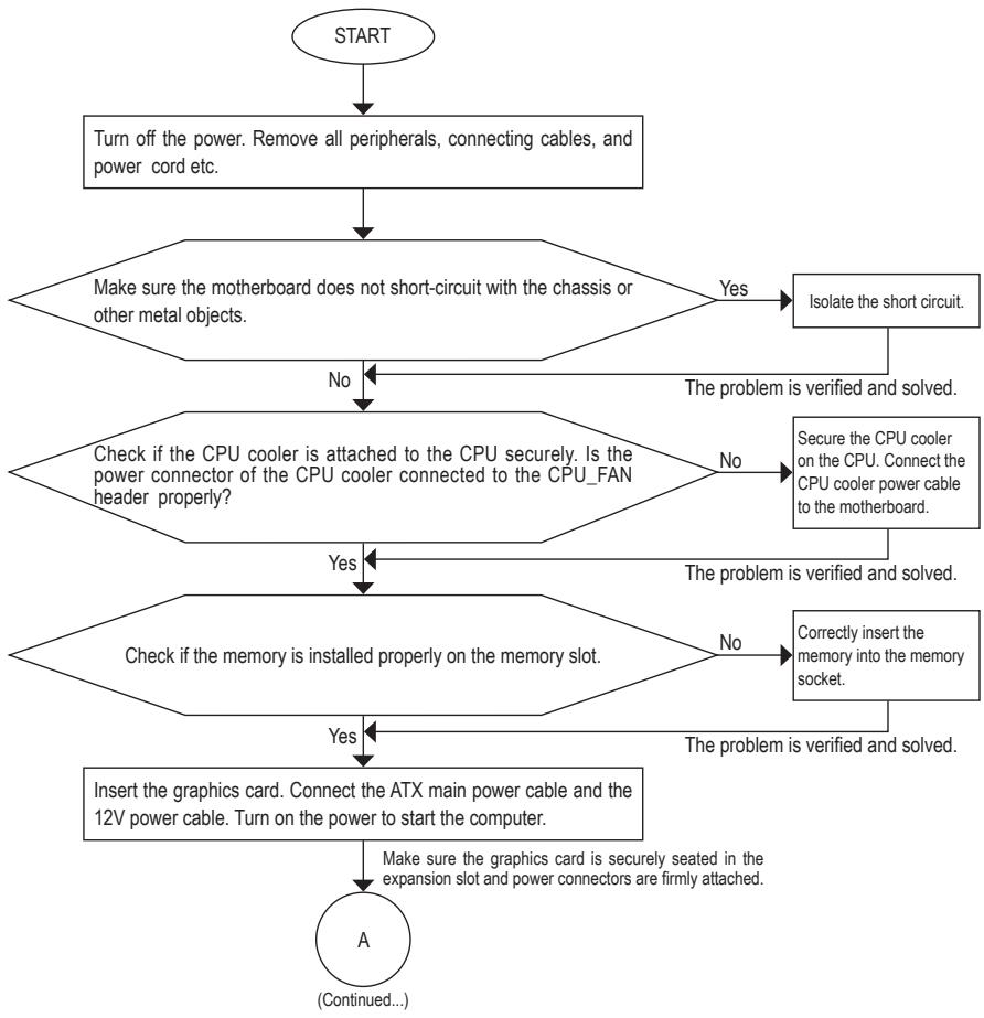
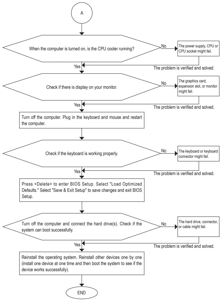

If the procedure above is unable to solve your problem, contact the place of purchase or local dealer for help. Or go to the Support & Downloads\Technical Support page to submit your question. Our customer service staff will reply you as soon as possible.
Regulatory Statements
Regulatory Notices
This document must not be copied without our written permission, and the contents there of must not be imparted to a third party nor be used for any unauthorized purpose. Contravention will be prosecuted. We believe that the information contained herein was accurate in all respects at the time of printing. GIGABYTE cannot, however, assume any responsibility for errors or omissions in this text. Also note that the information in this document is subject to change without notice and should not be construed as a commitment by GIGABYTE.
Our Commitment to Preserving the Environment
In addition to high-efficiency performance, all GIGABYTE motherboards fulfill European Union regulations for RoHS (Restriction of Certain Hazardous Substances in Electrical and Electronic Equipment) and WEEE (Waste Electrical and Electronic Equipment) environmental directives, as well as most major worldwide safety requirements. To prevent releases of harmful substances into the environment and to maximize the use of our natural resources, GIGABYTE provides the following information on how you can responsibly recycle or reuse most of the materials in your "end of life" product.
Restriction of Hazardous Substances (RoHS) Directive Statement
GIGABYTE products have not intended to add and safe from hazardous substances (Cd, Pb, Hg, Cr+6, PBDE and PBB). The parts and components have been carefully selected to meet RoHS requirement. Moreover, we at GIGABYTE are continuing our efforts to develop products that do not use internationally banned toxic chemicals.
Waste Electrical & Electronic Equipment (WEEE) Directive Statement
GIGABYTE will fulfill the national laws as interpreted from the 2002/96/EC WEEE (Waste Electrical and Electronic Equipment) directive. The WEEE Directive specifies the treatment, collection, recycling and disposal of electric and electronic devices and their components. Under the Directive, used equipment must be marked, collected separately, and disposed of properly.
WEEE Symbol Statement

The symbol shown below is on the product or on its packaging, which indicates that this product must not be disposed of with other waste. Instead, the device should be taken to the waste collection centers for activation of the treatment, collection, recycling and disposal procedure. The separate collection and recycling of your waste equipment at the time of disposal will help to conserve natural resources and ensure that it is recycled in a manner that protects human health and the environment.
For more information about where you can drop off your waste equipment for recycling, please contact your local government office, your household waste disposal service or where you purchased the product for details of environmentally safe recycling.
When your electrical or electronic equipment is no longer useful to you, "take it back" to your local or regional waste collection administration for recycling.
If you need further assistance in recycling, reusing in your "end of life" product, you may contact us at the Customer Care number listed in your product's user's manual and we will be glad to help you with your effort.
Finally, we suggest that you practice other environmentally friendly actions by understanding and using the energy-saving features of this product (where applicable), recycling the inner and outer packaging (including shipping containers) this product was delivered in, and by disposing of or recycling used batteries properly. With your help, we can reduce the amount of natural resources needed to produce electrical and electronic equipment, minimize the use of landfills for the disposal of "end of life" products, and generally improve our quality of life by ensuring that potentially hazardous substances are not released into the environment and are disposed of properly.
FCC Notice (U.S.A. Only)
This equipment generates, uses, and can radiate radio frequency energy and, if not installed and used in accordance with the instructions, may cause harmful interference to radio communications. However, there is no guarantee that interference will not occur in a particular installation. If this equipment does cause harmful interference to radio or television reception, which can be determined by turning the equipment off and on, the user is encouraged to try to correct the interference by one or more of the following measures:
- Reorient or relocate the receiving antenna.
- Increase the separation between the equipment and receiver.
- Connect the equipment into an outlet on a circuit different from that to which the receiver is connected.
- Consult a dealer or experienced TV/radio technician for help.
Properly shielded and grounded cables and connectors must be used in order to meet FCC emission limits. Neither the Dealer nor the Manufacturer are responsible for any radio or television interference caused by using other than recommended cables and connectors or by unauthorized changes or modifications to this equipment. Unauthorized changes or modifications could void the user's authority to operate the equipment.
European Community Directive R&TTE Directive Compliance Statement:
This equipment complies with all the requirements and other relevant provisions of Directive 1999/5/EC of the European Parliament and the Council of March 9, 1999 on Radio Equipment and Telecommunication Terminal Equipment (R&TTE).
This equipment is suitable for home and office use in all the European Community Member States and EFTA Member States.
Taiwan NCC Wireless Statements/無線設備警告聲明:
低功率電波輻射性電機管理辦法
Korea KCC NCC Wireless Statement:
Japan Wireless Statement:
Address: No.6, Bao Chiang Road, Hsin-Tien Dist.,
New Taipei City 231, Taiwan
TEL: +886-2-8912-4000
FAX: +886-2-8912-4005
Tech. and Non-Tech. Support (Sales/Marketing) :
G.B.T. INC (USA) - Mexico
Tel: +1-626-854-9338 x 215 (Sopporté de haberhispano)
FAX: +1-626-854-9326
Correo: soporte@gigabyte-usa.com
Tech. Support: http://rma.gigabyte.us
Web address: http://latam.giga-byte.com
Giga-Byte SINGAPORE PTE. LTD.-Singapore
WEB address : http://www.gigabyte.sg
Thailand
WEB address : http://th.giga-byte.com
Vietnam
WEB address: http://www.gigabyte.vn
- NINGBO G.B.T. TECH. TRADING CO., LTD. - China
WEB address: http://www.gigabyte.cn
Shanghai
TEL: +86-21-63400912
FAX: +86-21-63400682
Beijing
TEL: +86-10-62102838
FAX: +86-10-62102848
Wuhan
TEL: +86-27-87685981
FAX: +86-27-87579461
GuangZhou
TEL: +86-20-87540700
FAX: +86-20-87544306
Chengdu
TEL: +86-28-85483135
FAX: +86-28-85256822
Xian
TEL: +86-29-85531943
FAX: +86-29-85510930
Shenyang
TEL: +86-24-83992342
FAX: +86-24-83992102
GIGABYTE TECHNOLOGY (INDIA) LIMITED - India
WEB address: http://www.gigabyte.in
Saudi Arabia
WEB address: http://www.gigabyte.com.sa
Gigabyte Technology Pty. Ltd. - Australia
WEB address: http://www.gigabyte.com.au
G.B.T. TECHNOLOGY TRADING GMBH - Germany
WEB address : http://www.gigabyte.de
G.B.T. TECH. CO., LTD. - U.K.
WEB address: http://www.giga-byte.co.uk
Giga-Byte Technology B.V. - The Netherlands
WEB address : http://www.giga-byte.nl
GIGABYTE TECHNOLOGY FRANCE - France
WEB address: http://www.gigabyte.fr
Sweden
WEB address : http://www.gigabyte.se
Italy
WEB address : http://www.giga-byte.it
Spain
WEB address : http://www.giga-byte.es
Greece
WEB address: http://www.gigabyte.com.gr
Czech Republic
WEB address: http://www.gigabyte.cz
Hungary
WEB address : http://www.giga-byte.hu
Turkey
WEB address: http://www.gigabyte.com.tr
Russia
WEB address: http://www.gigabyte.ru
Poland
WEB address: http://www.gigabyte.pl
Ukraine
WEB address: http://www.gigabyte.ua
- Romania
WEB address : http://www.gigabyte.com.ro
Serbia
WEB address: http://www.gigabyte.co.rs
- Kazakhstan
WEB address: http://www.gigabyte.kz
You may go to the GIGABYTE website, select your language in the language list on the top right corner of the website.
GIGABYTE Global Service System

To submit a technical or non-technical (Sales/Marketing) question, please link to:
Then select your language to enter the system.