
DCS-6616 - Surveillance Camera D-LINK - Free user manual and instructions
Find the device manual for free DCS-6616 D-LINK in PDF.


| Product Type | Outdoor PTZ Network Camera |
| Model | DCS-6616 |
| Brand | D-Link |
| Image Sensor | 1/4" Progressive Scan CMOS |
| Resolution | 640x480 (VGA) at 30 fps |
| Lens | 3.3-12mm varifocal, F1.4 |
| Pan/Tilt Range | Pan: 0° to 360°, Tilt: 0° to 90° |
| Night Vision | Infrared LEDs up to 15 meters |
| Compression | H.264, MPEG-4, MJPEG |
| Network Interface | 10/100 Ethernet RJ-45 |
| Wireless | 802.11b/g/n (optional) |
| Power Supply | 12V DC, 1.5A (PoE 802.3af compatible) |
| Power Consumption | Max 10W |
| Dimensions | 160 x 140 x 110 mm (6.3 x 5.5 x 4.3 in) |
| Weight | 850 g (1.87 lb) |
| IP Rating | IP66 (weatherproof) |
| Operating Temperature | -20°C to 50°C (-4°F to 122°F) |
| Main Functions | Motion detection, alarm input/output, two-way audio, SD card recording (up to 32GB) |
| Maintenance & Cleaning | Clean lens with soft dry cloth; avoid water jets |
| Safety | IP66, surge protection, CE, FCC |
| Spare Parts & Repairability | Contact D-Link support; no user-serviceable parts |
Frequently Asked Questions - DCS-6616 D-LINK
User questions about DCS-6616 D-LINK
0 question about this device. Answer the ones you know or ask your own.
Ask a new question about this device
Download the instructions for your Surveillance Camera in PDF format for free! Find your manual DCS-6616 - D-LINK and take your electronic device back in hand. On this page are published all the documents necessary for the use of your device. DCS-6616 by D-LINK.
USER MANUAL DCS-6616 D-LINK
D-Link®
SURVEILLANCE
Table of Contents
Product Overview 3
Package Contents ....3
System Requirements 3
Introduction 4
Features 4
Resetting the Camera 5
Mount Instructions 6
D-ViewCam Device Pack Setup 17
Live Video 18
Setup 21
Internet Connection Setup Wizard 21
Motion Detection Setup Wizard .....24
Network Setup 26
Dynamic DNS 28
Image Setup 29
Audio and Video 31
PTZ Setup 32
Preset 34
Motion Detection 36
Time and Date 37
Event Setup 38
Application 39
Add Server 40
Add Media 41
Add Event 44
Recording 45
Advanced 46
DI and DO (Digital Input/Output) 46
ICR 47
HTTPS 48
Access List 49
Maintenance 50
Admin 50
Backup and Restore 51
Firmware Upgrade 52
Status 53
Device Info 53
Logs 54
Help 55
DI/DO Configuration 56
DI/DO Pin Block Specifications 56
Digital Input Diagram 57
Digital Output Diagram 58
Technical Specifications.... 59
Section 1 - Product Overview
Preface
D-Link reserves the right to revise this publication and to make changes in the contents hereof without obligation to notify any person or organization of such revisions or changes.
Manual Revisions
Revision Date Description
1.0 July 22, 2011 DCS-6616 Revision A1 with firmware version 2.00
Trademarks
D-Link and the D-Link logo are trademarks or registered trademarks of D-Link Corporation or its subsidiaries in the United States or other countries. All other company or product names mentioned herein are trademarks or registered trademarks of their respective companies.
Copyright © 2010-2011 by D-Link Systems, Inc.
All rights reserved. This publication may not be reproduced, in whole or in part, without prior expressed written permission from D-Link Systems, Inc.
Package Contents
• DCS-6616 High Speed Dome Network Camera • Data Cable for Video, Audio, Alarm, and Power - Power Adapter - Power Cable - Optical Cover - Manual and Software on CD - Quick Installation Guide - Screws - Mounting Bracket and Screws
If any of the above items are missing, please contact your reseller.
System Requirements
• CPU: Pentium 4 1.4GHz or above • Hard Disk: 40GB or above • Memory: 256MB or above • Browser: Internet Explorer 6.0 or above • Video Resolution: SVGA or XGA (1024x768 or above)
Introduction
The DCS-6616 Speed Dome Network Camera is a professional IP surveillance solution that connects to your network to provide high-quality live video over the Internet. The camera supports precise high-speed pan/tilt/zoom functionality for extensive monitoring and object tracking.
Hardware Overview

Resetting the Camera
The DCS-6616 contains both digital and mechanical components. Thus, if any problems are experienced with the camera, there are two different reset options depending on the type of problem.
Mechanical Reset
If the mechanical PTZ controls ever stop responding or seem to be locked up, you may reset the mechanical portion of the camera using the communication pin array at the base of the device.
- Use a small tool to move switch 5 to the "off" position.
- Plug the camera in for one minute and allow the device to initialize.
- Return the pin back to its original "on" position.
- Plug in the camera, and the device should successfully initialize.

Digital Reset
If the camera's web user interface ever becomes unresponsive, or if the administrator password is forgotten, it may become necessary to reset the device firmware to its original factory settings.
- Press and hold the green button on the base of the camera for a few seconds.
- Allow a few minutes for the camera to re-initialize to factory default settings.

Mount Instructions
Detach the Decoration Ring from the Hard Ceiling Mount Bracket.
Align the three holes on the Mount Bracket, mark the screw locations on the ceiling.
Drill three pilot holes into the ceiling and hammer the plastic anchors into the holes.
Fix the Mount Bracket with three screws.
![graph TD A["Initial circular component"] --> B["Step 1: Insert fastener"] B --> C["Step 2: Insert fastener"] C --> D["Step 3: Insert fastener"] D --> E["Step 4: Insert fastener"] E --> F["Final assembled circular component with screw fasteners"]](/content/2026/06/1392271/images/9b72f93326b62ee3404e9930f6f5c38402df10270590170751f580cdc3f8fde2.jpg)
Insert the fixing plate into the groove as shown below.
Align the three holes to screw the fixing plate to the dome base.
Connect the cable connector and Ethernet cable to the dome base.
Align plate A and plate B, then use those three holes to hook the Network Camera onto the ceiling mount bracket.
![graph TD A["Component 1: Top Left"] --> B["Component 2: Top Right"] B --> C["Component 3: Bottom Left"] C --> D["Component 4: Bottom Right"] D --> E["Final Assembly: Component A and B with labeled parts"]](/content/2026/06/1392271/images/c5199e4fe5f54efdd6a8ac52b8b72ab26c32f1c19b85870ef2eefeaaf053bd26.jpg)
Tighten the screw on the fixing plate.
Align the three holes to mount the decoration ring.

Configuration
Configuration with Wizard
Insert the DCS-6616 CD into your computer's CD-ROM drive to begin the installation. If the Autorun function on your computer is disabled, or if the D-Link Launcher fails to start automatically, click Start > Run. Type D:\autorun.exe, where D: represents the drive letter of your CD-ROM drive.
Click Setup Wizard to begin the installation.

Click Next to continue.

Click Yes to accept the License Agreement.

To start the installation process, click Next.
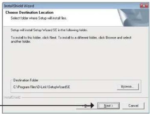
Note: The installation may take several minutes to finish.
Click Finish to complete the installation.

Click on the D-Link Setup Wizard SE icon that was created in your Windows Start menu.
Start > D-Link > Setup Wizard SE

The Setup Wizard will appear and display the MAC address and IP address of your camera(s). If you have a DHCP server on your network, a valid IP Address will be displayed. If your network does not use a DHCP server, the network camera's default static IP address 192.168.0.20 will be displayed.
Click the Wizard button to continue.

Enter the Admin ID and password. When logging in for the first time, the default Admin ID is admin with the password left blank.
Click Next, to proceed to the next page.

Select DHCP if your camera obtains an IP address automatically when it boots up. Select Static IP if the camera will use the same IP address each time it is started.
Click Next, to proceed to the next page.

Take a moment to confirm your settings and click Restart.
![D-Link SECURICAM Network. Admin ID: admin. Password: [blank]. IP Address: 192.168.0.102. Subnet Mask: 255.255.256.0. Primary DNS: 192.168.0.1. Secondary DNS: 192.168.0.1. The Setup Wizard has completed. Click on 'Back' to modify your settings. Click 'Restart' to save your current settings and reboot…](/content/2026/06/1392271/images/c48a5d1e4c2fa32a67a6b946518a00ca7c1590bcfaee41d2ae3e244335f50867.jpg)
Web-based Configuration Utility
This section explains how to configure your new D-Link Network Camera using the Web-based Configuration Utility.
Click on the D-Link Setup Wizard SE icon that was created in your Windows Start menu.
Start > D-Link > Setup Wizard SE

Select the camera and click the button labeled "Link" to access the web configuration.

The Setup Wizard will automatically open your web browser to the IP address of the camera.
Alternatively, you may manually open a browser and enter the IP address of the camera: 192.168.0.20

Enter admin as the default username and leave the password blank. Click OK to continue.
![Connect to 192.168.0.20. The server 192.168.0.20 at DCS-6616 requires a username and password. Warning: This server is requesting that your username and password be sent in an insecure manner (basic authentication without a secure connection). User name: admin. Password: [blank]. Remember my passwor…](/content/2026/06/1392271/images/8e511cc507032450cfa5180cb86542bdc1627dcced42261977842ae4d4a2fa58.jpg)
This section shows your camera's live video. You can select your video profile and view or operate the camera. For additional information about web configuration, please refer to the user manual included on the CD-ROM or the D-Link website.

D-ViewCam Setup Wizard
D-ViewCam software is included for the administrator to manage multiple D-Link IP cameras remotely. You may use the software to configure all the advanced settings for your cameras. D-ViewCam is a comprehensive management tool for IP surveillance.
Insert the CD-ROM into the CD-ROM drive. Click "Install D-ViewCam Software" from menu, and select "D-ViewCam" to install the VMS software.
Follow the Installation Wizard to install D-ViewCam.


Section 3 - Configuration
Click Finish to complete the installation.
To start D-ViewCam, select Start > All Programs > D-Link D-ViewCam > Main Console.
For more detailed operation of using D-ViewCam software, please refer to the D-ViewCam Manual.


Live Video
This page displays live video and allows you to adjust and save camera images.
On-screen Display (OSD): The date, time, and camera name are displayed at the top left corner of the live video display.

Digital Input
Indicators (1-8): These indicators blink when digital input is received.

Motion Trigger
Indicator: This indicator blinks when motion is detected.

Recording
Indicator: This indicator blinks when the camera is recording.
Navigation Pad: The navigation pad is used to carry out pan, tilt, and zoom functions. The camera can be aimed and the image adjusted using this pad (Up/Down/Left/Right/Home).
Zoom In/Zoom Out
Note: The Home position of the dome camera is not configured by default. Please see page 35 for information about how to configure the home position.
Pan Speed: There are 16 speeds for pan control. 1 is the slowest and 16 is the fastest.
Tilt Speed: There are 16 speeds for tilt control. 1 is the slowest and 16 is the fastest.

Section 3 - Configuration

AutoPan: Starts a pre-defined AutoPan movement. Select the number corresponding to a predefined path.

Sequence: Starts a pre-defined sequence movement. Select the number corresponding to a predefined path.

Cruise: Starts a pre-defined cruise movement. Select the number corresponding to a predefined path.

Autofocus
(AF): Click this button to enable automatic focus.

Manual
Focus (MF): Click this button to manually focus the camera image.

Focus: Use these controls to focus the camera image.

Language: You may select English or Traditional Chinese.
Fullscreen: Loads the live camera image in fullscreen.

Snapshot: Saves a snapshot of the image to the specified location.

Start/Stop Recording: Begins recording to the specified location. Pressing this button a second time will stop the recording.

Set Storage Folder: Designates a folder where snapshots and video will be saved.

Start/Stop
Digital Output: Sends a signal to the attached digital device.

Section 3 - Configuration


Profile 1-3: Select one of three predefined video profiles to display in the Live Video window.

Start/Stop
Listening: Click this button to begin listening to the audio feed from a microphone connected to the camera (audio in).

Start/Stop
Talking: Click this button to begin sending audio to speakers connected to the camera (audio out).
GoTo --Preset List--
Go To (Preset): Selecting a preset from this list will load the preset in the Live Video windows.
Setup
To configure your Network Camera, click Internet Connection Setup Wizard. Alternatively, you may click Manual Internet Connection Setup to manually configure your Network Camera and skip to page 27.
To quickly configure your Network Camera's motion detection settings, click Motion Detection Setup Wizard. If you want to enter your settings without running the wizard, click Manual Motion Detection Setup and skip to page 37.

Internet Connection Setup Wizard
This wizard will guide you through a step-by-step process to configure your new D-Link Camera and connect the camera to the internet. Click Next to continue.
Note: Select DHCP if you are unsure of which settings to choose.
Click Next to continue.

Section 3 - Configuration
Select Static IP if your Internet Service Provider has provided you with connection settings, or if you wish to set a static address within your home network. Enter the correct configuration information and click Next to continue.
If you are using PPPoE, select Enable PPPoE and enter your user name and password, otherwise click Next to continue.
If you have a Dynamic DNS account and would like the camera to update your IP address automatically, Select Enable DDNS and enter your host information. Click Next to continue.
Enter a name for your camera and click Next to continue.
Step 1: Setup LAN Settings
Step 2: Setup DDNS Settings
Step 3: Camera Name Settings
Section 3 - Configuration
Configure the correct time to ensure that all events will be triggered as scheduled. Click Next to continue.
If you have selected DHCP, you will see a summary of your settings, including the camera's IP address. Please write down all of this information as you will need it in order to access your camera.
Click Apply to save your settings.


Motion Detection Setup Wizard
This wizard will guide you through a step-by-step process to configure your camera's motion detection functions.
Click Next to continue.
Step 1
This step will allow you to enable or disable motion detection, specify the detection sensitivity, and adjust the camera's ability to detect movement.
You may specify whether the camera should capture a snapshot or a video clip when motion is detected.
Please see the Motion Detection section on page 43 for information about how to configure motion detection.
Step 2
This step allows you to enable motion detection based on a customized schedule. Specify the day and hours. You may also choose to always record motion.


Section 3 - Configuration
Step 3
This step allows you to specify how you will receive event notifications from your camera. You may choose not to receive notifications, or to receive notifications via e-mail or FTP.
Please enter the relevant information for your e-mail or FTP account.
Click Next to continue.

Step 4
You have completed the Motion Detection Wizard.
Please verify your settings and click Apply to save them.

Please wait a few moments while the camera saves your settings and restarts.

Network Setup
Use this section to configure the network connections for your camera. All relevant information must be entered accurately.
LAN Settings: Settings for your local area network.
DHCP: Select this connection if you have a DHCP server running on your network and would like your camera to obtain an IP address automatically.
Static IP Address: You may obtain a static or fixed IP address and other network information from your network administrator for your camera. A static IP address may simplify access to your camera in the future.
IP Address: Enter the fixed IP address in this field.
Subnet Mask: This number is used to determine if the destination is in the same subnet. The default value is 255.255.255.0.
Default Gateway: The gateway used to forward frames to destinations in a different subnet. Invalid gateway settings may cause the failure of transmissions to a different subnet.
Primary DNS: The primary domain name server translates names to IP addresses.
Secondary DNS: The secondary DNS acts as a backup to the primary DNS.
Enable UPnP: Enabling this setting allows your camera to be configured as a UPnP device on your network.
Enable UPnP Port Forwarding: Enabling this setting allows the camera to add port forwarding entries into the router automatically on a UPnP capable network.

Enable PPPoE: Enable this setting if your network uses PPPoE.
User Name: The unique name of your account. You may obtain this information from your ISP.
Password: The password to your account. You may obtain this information from your ISP.
HTTP Port: The default port number is 80.
Access Name for the stream: The default name is video#.mjpg, where # is the number of the stream (1~3).
HTTPS Port: You may use a PC with a secure browser to connect to the HTTPS port of the camera. The default port number is 443.
RTSP Port: The port number that you use for RTSP streaming to mobile devices, such as mobile phones or PDAs. The default port number is 554. You may specify the address of a particular stream. For instance, live1.sdp can be accessed at rtsp://x.x.x.x/video1.sdp where the x.x.x.x represents the IP address of your camera.
Maximum Upload/Download Bandwidth: Specifying the maximum download/upload bandwidth for each socket can be useful when connecting your device to a busy or heavily loaded network. Entering a value of '0' indicates that the camera should not monitor bandwidth. Specifying other values will limit the camera's transfer speed to the specified number of Kilobytes per second.

Dynamic DNS
DDNS (Dynamic Domain Name Server) will hold a DNS host name and synchronize the camera's public IP address when it has been modified. A user name and password are required when using the DDNS service.
Enable DDNS: Select this checkbox to enable the DDNS function.
Server Address: Select your Dynamic DNS provider from the drop-down menu or enter the server address manually.
Host Name: Enter the host name of the DDNS server.
User Name: Enter your user name or e-mail used to connect to the DDNS.
Password: Enter your password used to connect to the DDNS server.
Timeout: Enter DNS Timeout values.
Status: Indicates the connection status, which is automatically determined by the system.

Adjustments to these settings will affect the amount of network resources that the camera will use.
Enable Privacy
Mask: Select this checkbox to enable the privacy mask.
Transparency: Turning transparency on allows you to see through the privacy mask area.
Color: This is the color that will be displayed over the masked area.
Number: Select which mask area you would like to set. You may set up to 16 different masked areas.
H Size: Specifies the horizontal length of the masked area in pixels.
V Size: Specifies the vertical length of the masked area in pixels.

BLC: This function will enable backlight compensation, if the object is in front of strong backlight.
WDR: Wide Dynamic Range - This function allows the camera to be installed in high contrast and backlit environments.
White Balance: It is the process of removing unrealistic color casts, so that an object appears white in person that is correctly rendered as white on the screen.
Flip: You may choose Mechanical (M.E.) Flip or Image (digital) Flip. Mechanical Flip uses the PTZ mechanism, while Image Flip uses the digital system to flip the image.
Inverse: Turn this option on to invert the image.
AE Mode: This feature automatically sets the aperture and shutter speed if Auto is selected. If Manual is selected, you may specify the shutter speed and gain. You may also select Shutter Priority and specify the shutter speed.
Brightness: Adjust this control to compensate for brightly backlit camera images.
Contrast: Adjust this control to increase or decrease the contrast of the camera image.
Saturation: Adjust this control to increase or decrease the color saturation of the picture.
Sharpness: This function controls the amount of sharpening applied to the image.
Excomp: Exposure compensation can be used to adjust exposure.
Reset to Defaults: Click this button to reset these settings to their defaults.

Audio and Video
You may configure 3 video profiles with different settings for your camera. Hence, you may set up different profiles for your computer and mobile display. In addition, you may also configure the two-way audio settings for your camera.
Mode: You may select H.264, MPEG4, or MJPEG encoding.
Frame Size: This option allows the user to choose the video resolution of the camera. The options include NTSC: D1 (720x480), CIF (352x240), QCIF (176x120) and PAL: D1 (720x576), CIF (352x288), QCIF (176x144).
Maximum Frame Rate: A higher frame rate provides smoother motion for video. Lower frame rates will result in stuttering.
Video Quality: Select the number of frames to be captured per second. 30fps is the highest video quality for this device.
Constant Bit Rate: This limits the maximal refresh frame rate, which can be combined with the "Fixed quality" to optimize the bandwidth utilization and video quality. To set the bandwidth utilization regardless of the video quality, choose "Constant bit rate" and select the desired bandwidth.
Fixed Quality: Select the image quality level of the video. You may choose Standard, Good, or Excellent.
Audio In Off: Select this option to disable Audio In.
Audio In Gain Level: Select 20 or 26 dB to make the audio louder.
Audio Out Off: Select this option to disable Audio Out.
Audio Out Volume
Level: Choose a level between 1 and 10.

PTZ Setup
This page allows you to configure the pan/tilt/zoom settings for the camera. Changes to settings on this page take place immediately.
Auto Pan: Auto Pan scans an area horizontally from left to right or right to left. Up to 4 Auto Pan paths may be defined. Select the button next to the path that you would like to set. Use the navigation pad to move the camera view to the desired start point and click Set Start Point. Move the camera view to the desired end point and click Set End Point. You may also specify the pan direction and speed. Click the Test button to view the path that you have just defined. Click Stop to end the test.
Cruise: A Cruise path is a stored route defined through manual adjustment of pan, tilt, and zoom. Up to 4 Cruise paths may be defined. Select the button next to the path that you would like to set. Click Record Start to begin recording a path. Use the navigation pad or mouse to define a path within the live video window. Click Record End when you are done defining the path. Click the Test button to view the path that you have just defined. Click Stop to end the test.
Home: You may turn on the home function and specify the PTZ behavior.
Digital Zoom: You may turn digital zoom on or off.
Freeze: If this option is turned on, the image will freeze at the end of the predefined path and return to the starting point.

Section 3 - Configuration
Auto Calibration: Turning this option on will automatically calibrate the camera when needed to ensure that the
2DNR: This option turns on 2D noise reduction which may improve picture quality.
3DNR: This option turns on 3D noise reduction which may further improve image quality.
Tilt Angle: The option allows you to adjust the minimum and maximum tilt angle of the camera.

Preset
This page allows you to define presets and a preset sequence for the camera image.
Preset: Use the navigation pad or mouse to target a specific view in the live video window. You may adjust the pan and tilt speed if needed.
Create a New Preset
- Select the page number, between 1 and 26.
- Select an unused preset number from the preset list.
- Choose a name for the preset.
- Click Add.
Remove a Preset
- Select the page number.
- Select the preset from the preset list.
- Click Remove.
Rename a Preset
- Select the page number.
- Select the preset from the preset list.
- Enter a new name for the preset, overwriting the old name.
- Click Rename.
Set a Preset as the Home Position
- Select the page number.
- Select the preset from the preset list.
- Click Set.
Reset the Home Position to Default
- Click Default.

Section 3 - Configuration
Preset Sequence: Sequence is an automated series of camera movements from one preset position to another. A sequence can be set up to display the video streams from different preset positions in a pre-determined order, and for configurable time periods.
Before creating a sequence, you must first define some presets. (Please see the previous page.)
Define a Preset Sequence
- Specify a path number to use.
- Specify up to 64 point numbers using the Prev Page and Next Page buttons to navigate between the sequence preset numbers:
a. Select a preset point from the Preset List.
b. Specify the Dwell Time.
c. Specify the Camera Speed.
- Repeat steps a, b, and c for up to 64 points.
- Click Save to save your preset sequence.

Motion Detection
This section allows you to enable and configure motion detection areas.
Enable Video Motion: Select this box to enable the motion detection feature of your camera.
Sensitivity: Specifies the measurable difference between two sequential images that would indicate motion. Please enter a value between 0 and 100.
Specifies the amount of motion in the window being monitored that is required to initiate an alert. If this is set to 100%, motion detected within the whole window will trigger a snapshot.
Draw Motion Area: Draw the motion detection area by dragging your mouse in the window (indicated by the red square).
Erase Motion Area: To erase a motion detection area, simply click on the red square that you wish to remove.
Right clicking on the camera image brings up the following menu options:
Select All: Draws a motion detection area over the entire screen.
Clear All: Clears any motion detection areas that have been drawn.
Restore: Restores the previously specified motion detection areas.


Save Settings Don't Save Settings
Time and Date
This section allows you to automatically or manually configure, update, and maintain the internal system clock for your camera.
Time Zone: Select your time zone from the drop-down menu.
Enable Daylight
Saving: Select this to enable Daylight Saving Time.
Auto Daylight Select this option to allow your camera to configure the Saving: Daylight Saving settings automatically.
Set Date and Time Selecting this option allows you to configure the Daylight Manually: Saving date and time manually.
Offset: Sets the amount of time to be added or removed when Daylight Saving is enabled.
Synchronize with Enable this feature to obtain time automatically from an NTP Server: NTP server.
NTP Server: Network Time Protocol (NTP) synchronizes the DCS-6616 with an Internet time server. Choose the one that is closest to your location.
Set the Date and
Time Manually: This option allows you to set the time and date manually.
Copy Your
Computer's Time
Settings: This will synchronize the time information from your PC.

Event Setup
The Event Setup page includes four different sections.
- Event
- Server
- Media
- Recording
- To add a new item - "event, server or media," click Add. A screen will appear and allow you to update the fields accordingly.
- To delete the selected item from the drop-down menu of event, server or media, click Delete.
- Click on the item name to pop up a window for modifying.
Note: You can add up to four events, five servers, and five media fields.

Application
In a typical application, when motion is detected, the DCS-6616 Network Camera sends images to a FTP server or via e-mail as notifications. As shown in the illustration below, an event can be triggered by many sources, such as motion detection or external digital input devices. When an event is triggered, a specified action will be performed. You can configure the Network Camera to send snapshots or videos to your e-mail address or FTP site.
![graph TD A["Event Condition"] --> B["Action"] B --> C["Media (what to send)"] B --> D["Server (where to send)"] C -->|ex. Snapshot, Video Clips| E D -->|ex. Email, FTP| F style A fill:#ccc,stroke:#333 style B fill:#ccc,stroke:#333 style C fill:#ccc,stroke:#333 style D fill:#ccc,stroke:#333](/content/2026/06/1392271/images/ec981ed40207d0d87e8a4c7ee23768b4a66c14152f1f9fa9344934892379bbb6.jpg)
To start plotting an event, it is suggested to configure server and media columns first so that the Network Camera will know what action shall be performed when a trigger is activated.
Add Server
Configure up to 5 servers to store media.
Server Name: Enter the unique name of your server.
E-mail: Enter the configuration for the target e-mail server account.
FTP: Enter the configuration for the target FTP server account.
Network Storage: Specify a network storage device. Only one network storage device is supported.

Add Media
There are three types of media: Snapshot, Video Clip, and System Log.
Media Name: Enter a unique name for media.
Snapshot: Select this option to enable snapshots.
Source: The stream source: Profile 1, Profile 2 or Profile 3.
Send pre-event
image(s) [0~4]: The number of pre-event images.
Send post-event
image(s) [0~7]: The number of post-event images.
File name prefix: The prefix name will be added on the file name.
Add date and time
suffix to file name: Check it to add timing information as file name suffix.
Video clip: Select this option to enable video clips.
Source: The source of the profile: profile1, profile2, or profile3.
Pre-event recording: The interval of pre-event recording in seconds.
Maximum duration: The maximal recording file duration in seconds.
Maximum file size: The maximal file size would be generated.
File name prefix: The prefix name will be added on the file name of the video clip.
System log: Select this option to save events to the camera system log.
![D-Link Live Video STMP ADVANCED MAINTENANCE STATUS HELP HEGA You can set at most 5 different media here for different events. Save Settings Don't Save Settings HEGA TYPE Media name: Project Source: Profile 1 Send 1 pre-project map(s) [0=4] Send 2 post-project map(s) [0=7] File Name Profile: Add data…](/content/2026/06/1392271/images/6e8ea01f8074cf3c0dd8d4f35d29067693c70fd2eea44bea157d338ccd225354.jpg)
Send post-event image(s) [0~7)
Specify the number of images to capture after a trigger is activated. A maximum of seven images can be generated.
For example:
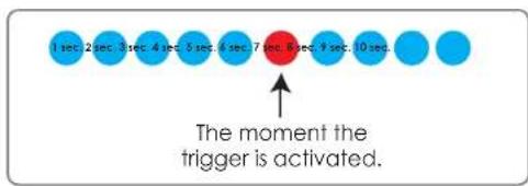
If both the Send pre-event images and Send post-event images are set to four, a total of 9 images are generated after a trigger is activated.

Add a date and time suffix to the file name
Select this option to add a date and time to the file name suffix.

Maximum duration
Specify the maximal recording duration in seconds. You can set up to ten seconds.
For example:
If the Pre-event recording is set to five seconds and the Maximum duration is set to ten seconds, the Network Camera continues to record for another four seconds after a trigger is activated.
Section 3 - Configuration
for another four seconds after a trigger is activated.
File name prefix
Enter the text that will be added at the beginning of the file name.

Add Event
Create and schedule up to three events with their own settings here.
Event name: Enter a name for the event.
Enable this event: Select this box to activate this event.
Priority: Set the priority for this event. The event with higher priority will be executed first.
Delay: Select the delay time before checking the next event. It is used for both events of motion detection and digital input trigger.
Trigger: Specify the input type that triggers the event.
Video Motion: Motion is detected during live video monitoring. Select the windows that need to be monitored.
Periodic: The event is triggered in specified intervals. The trigger interval unit is in minutes.
Digital Input: The external digital input trigger input to the camera.
System Boot: Triggers an event when the system boots up.
Network Lost: Triggers an event when the network is lost.
Time: Select Always or enter the time interval.
Trigger D/O: Select to trigger the digital output for a specific number of seconds when an event occurs.

Recording
Here you can configure and schedule the recording settings.
Recording entry
name: The unique name of the entry.
Enable this
recording: Select this to enable the recording function.
Priority: Set the priority for this entry. The entry with a higher priority value will be executed first.
Source: The source of the stream.
Recording
schedule: Scheduling the recording entry.
Recording settings: Configuring the setting for the recording.
Destination: Select the folder where the recording file will be stored.

Total cycling size: Please input a volume size between 1MB and 200GB for recording space. The recording data will replace the oldest recording when the total recording size exceeds this value. For example, if each recording file is 6MB, and the total cyclic recording size is 600MB, then the camera will record 100 files in the specified location (folder) and then will delete the oldest file and create new file for cyclic recording.
Please note that if there is not enough free space, the recording will stop. Before you set up this option please make sure that sufficient free space is available. It is better to not save other files in the same folder as recordings.
Size of each file for
recording: File size for each recording file. You may input the value in the range of 200-5000.
File Name Prefix: The prefix name will be added to the file name of the recording file(s).
Advanced DI and DO (Digital Input/Output)
The camera provides eight alarm inputs and one alarm output to connect alarm devices. With this function, the camera can cooperate with the alarm system to capture event images.
No. # DI Type: Normal Open is for digital input that is activated when the circuit is closed.
Normal Close is for digital input that is activated when the circuit is opened.
For example: Connect the Alarm input terminal to ALM GND to activate [NC] or floating (unconnected) [NO] to deactivate.


ICR
The Infrared Cut-Removable (ICR) filter can be disengaged for increased sensitivity in low light environments. The ICR filter will automatically engage depending on the ambient light, allowing the camera to be effective in day/night environments.
Automatic (Default): The day/night mode is set automatically. It will typically use day mode, but will use night mode if installed in a dark area.
Day Mode: The Day mode disables the IR Cut Filter.
Night Mode: The Night mode enables the IR Cut Filter.
Schedule Mode: You can specify a time period for which Day mode will always be used.

HTTPS
This page allows you to install and activate an HTTPS certificate for secure access to your camera.
Enable HTTPS
Secure Connection: Enable the HTTPS service.
Create Certificate: Choose how the certificate should be created. Three methods are available:
Create a self-signed certificate automatically Create a self-signed certificate manually Create a certificate request and install
Status: Displays the status of the certificate.
Note: The certificate cannot be removed while HTTPS is still enabled. To remove the certificate, you must first uncheck Enable HTTPS secure connection.

Access List
Here you can set access permissions for users to view your DCS-6616.
Allow list: The list of IP addresses that have access rights to the camera.
Start IP address: The starting IP address of devices (such as a computer) that have permission to access the camera's video. Click Add to save the changes made.
Note: A total of seven lists can be configured for both columns.
End IP address: The ending IP address of devices (such as a computer) that have permission to access the camera's video.
Delete allow list: Remove the customized setting from the Allow List.
Deny list: The list of IP addresses that have no access rights to the camera.
Delete deny list: Remove the customized setting from the Deny List.
For example:
When the range of the Allowed List is set from 1.1.1.0 to 192.255.255.255 and the range of the Denied List is set from 1.1.1.0 to 170.255.255.255, only users with IPs located between 171.0.0.0 and 192.255.255.255 can access the Network Camera.


Maintenance Admin
You may modify the name and administrator's password of your camera, as well as add and manage the user accounts for accessing the camera. You may also use this section to create the unique name and configure the OSD setting for your camera.
Admin Password
Setting: Set a new password for the administrator's account.
Add User Account: Add new user account.
User Name: The user name for the new account.
Password: The password for the new account.
User List: All the existing user accounts will be displayed here. You may delete accounts included in the list, but please reserve at least one as guest.
Camera Name: Create a unique name for your camera that will be added to the file name prefix when creating a snapshot or a video clip.
Enable OSD: Select this option to enable the On-Screen Display feature for your camera.
Label: Enter a label for the camera.
Show Time: Select this option to enable the time-stamp display on the video screen.

Backup and Restore
In this section, you may backup, restore and reset the camera configuration, or reboot the camera.
Save To Local Hard Drive: You may save and document your current settings into your computer.
Local From Local Hard Drive: Locate a pre-saved configuration by clicking Browse and then restore the pre-defined settings to your camera by clicking Load Configuration.
Restore to Factory Default: You may reset your camera and restore the factory settings by clicking Restore Factory Defaults.
Reboot Device: This will restart your camera.

Firmware Upgrade
The camera's current firmware version will be displayed on this screen. You may visit the D-Link Support Website to check for the latest available firmware version.
To upgrade the firmware on your DCS-6616, please download and save the latest firmware version from the D-Link Support Page to your local hard drive. Locate the file on your local hard drive by clicking the Browse button. Select the file and click the Upload button to start upgrading the firmware.
Current Firmware
Version: Displays the detected firmware version.
Current Product Name: Displays the camera model name.
File Path: Locate the file (upgraded firmware) on your hard drive by clicking Browse.
Locate the file (upgraded firmware) on your hard drive File Path: by clicking Browse.
Status

Device Info
Device Info
This section displays detailed information about your device and network settings.

Logs
This page displays the log information of your camera. You may download the information by clicking Download. You may also click Clear to delete the saved log information.

Help
This page provides helpful information regarding camera operation.

DI/DO Configuration DI/DO Pin Block Specifications
The network Speed Dome Camera's 22-pin connector definition is listed as shown below.

| Pin | Definition Cable | Pin Definition Cable | Pin | Definition | Cable |
| 1 | DC12V IN RED (18AWG) 2 ALM NC GND | WHITE | |||
| 3 | BLACK (18AWG) 4 ALM NO BLACK/ | WHITE | |||
| 5 | YELLOW (18AWG) 6 | ALM | COM GREEN/BLACK | ||
| 7 | Audio in YELLOW | 8 Audio out | ORANGE | ||
| 9 | Audio GND | GREEN | 10 | Audio GND | BROWN |
| 11 | ISOG | BLUE/WHITE | 12 | ALM-1 | RED/WHITE |
| 13 | ALM-3 | PURPLE | 14 | ALM-2 | GREY |
| 15 | ALM-4 | BLUE | 16 | ALM-5 | WHITE/BLACK |
| 17 | ALM-6 | ORANGE/BLACK | 18 | ALM-7 | PURPLE/WHITE |
| 19 | ALM-8 | GREY/BLACK | 20 | ALM GND BROWN/WHITE | |
| 21 | VGND | BLACK | 22 | Video RED |
Digital Input Diagram![graph TD A["Alarm1"] --> B["Diode 1"] B --> C["Resistor 2"] C --> D["ALM5"] E["Alarm2"] --> F["Diode 1"] F --> G["Resistor 2"] G --> H["ALM2"] I["Alarm3"] --> J["Diode 1"] J --> K["Resistor 2"] K --> L["ALM3"] M["Alarm4"] --> N["Diode 1"] N --> O["Resistor 2"] O --> P["ALM4"] Q["Alarm5"] --> R["Diod…](/content/2026/06/1392271/images/3746c81730d812c063ce214c1e34a103e3d83418f035d3928a3aa3ec0123a6c0.jpg)
Alarm Input: ALM-1 \~ 8 - ALM GND
Digital Output Diagram
Alarm Output: ALM NC / ALM NO – ALM COM (NC: normal close, NO: normal open) Max. load 3A, max. voltage 120V AC relay output.
Technical Specifications
| Camera | Camera Hardware Profile | ■ Sony Super HAD-II 1/4" CCD sensor■ 650 TVL resolution■ Minimum illumination: 0.1 lux (Color), 0.01 lux (B/W)■ Built-in Infrared-Cut Removable (ICR)■ Iter module■ Electronic shutter: 1 to 1/10000 second■ S/N ratio > 50 dB (AGC off) | ■ 12x optical zoom■ Fixed length: 3.8 to 45.6 mm■ Aperture: F1.6 to F2.7■ Angle of view:(H) 4.49° to 52.8°(V) 3.40° to 39.7°(D) 55.4° to 65.4° |
| PTZ Hardware Profile | ■ Pan travel: 360° endless■ Tilt travel: 10° to 170°■ Manual speed: 1° to 80°/second■ Presets: 256 points■ Preset Accuracy: 0.225°■ Preset Speed: 10° to 400°/second■ Sequence Paths: 8■ Auto Pan Paths: 4■ Cruise Paths: 8 | ■ Pan and tilt speed proportional to zoom ratio■ Resume after power loss■ Home Functions: Preset, Sequence, Auto Pan, Cruise■ Auto Flip: Mechanical/Digital/Off■ Digital Slow Shutter■ Image Freeze■ Image Inverse | |
| Image Features | ■ Configurable image size, quality, frame rate, and bit rate■ Time stamp and text overlays■ Configurable motion detection windows | ■ 16 configurable privacy masks■ Configurable white balance, shutter speed, brightness, saturation, contrast, sharpness | |
| Video Compression | ■ Simultaneous H.264/MPEG-4/MJPEG format compression■ JPEG for still image | ■ H.264/MPEG-4 multicast streaming | |
| Video Resolution | ■ NTSC: 720 x 480, 352 x 240, 176 x 120 at up to 30 fps■ PAL: 720 x 576, 352 x 288, 176 x 144 at up to 25 fps | ||
| Audio Support G.726 | |||
| External Device Interface | ■ 10/100 BASE-TX Ethernet port■ 8 Alarm inputs■ 1 Alarm outputs | ■ Audio input / output■ Video output | |
| Network | Network Protocols | IPv4, TCP/IP, UDP, ICMP, DHCP Client, NTP Client (D-Link), DNS Client, DDNS Client (D-Link), SMTP Client, FTP Client, HTTP / HTTPS, Samba Client, PPPoE, UPnP Port Forwarding, RTP / RTSP/ RTCP, IP Itering, 3GPP, IGMP, ONVIF Compliant | |
| Security | ■ Administrator and user group protection■ Password authentication | ■ HTTP and RTSP digest encryption | |
Appendix C - Technical Specifications
| System Management | System Requirements for Web Interface | ·Operating system: Microsoft Windows 7/Vista/XP/2000·Browser: Internet explorer, Firefox, Netscape, Mozilla, Opera | |
| Event Management | ·Motion detection·Event notification and upload snapshots/video clips via HTTP,·SMTP or FTP·Supports multiple HTTP, SMTP and FTP servers | ·Multiple event notification·Multiple recording methods for easy backup | |
| Remote Management | ·Configuration accessible via web browser·Take snapshots/video clips and save to local hard drive or NAS via web browser | ||
| Mobile Support Windows 7/Vista/XP system, Pocket PC, or mobile phone with 3GPP playback support | |||
| D-ViewCamTM System Requirements | ·Operating System: Microsoft Windows 7 / Vista / XP·Web Browser: Internet Explorer 6 or higher | ·Protocol: Standard TCP/IP | |
| D-ViewCamTM Software Functions | ·Remote management/control of up to 32 cameras·Viewing of up to 32 cameras on one screen | ·Supports all management functions provided in web interface·Scheduled motion triggered, or manual recording options | |
| General | Power Input DC 12 V / 2A | ||
| Max. Power Consumption | 14 W | ||
| Operating Temperature | 0° to 40°C (32° to 104°F) | ||
| Storage Temperature -20° to 70°C (-4° to 158°F) | |||
| Humidity 20% to 80% non-condensing | |||
| Weight 1.2 kg (2.6 lbs) | |||
| Certifications CE (Class A), CE LVD (EN60965-1), FCC (Class A), ICES-003, C-Tick | |||
Dimensions


- TABLE OF CONTENTS
- PRODUCT OVERVIEW
- DI/DO CONFIGURATION
- TECHNICAL SPECIFICATIONS
- PREFACE
- MANUAL REVISIONS
- TRADEMARKS
- PACKAGE CONTENTS
- SYSTEM REQUIREMENTS
- INTRODUCTION
- HARDWARE OVERVIEW
- RESETTING THE CAMERA
- MECHANICAL RESET
- DIGITAL RESET
- MOUNT INSTRUCTIONS
- CONFIGURATION
- CONFIGURATION WITH WIZARD
- WEB-BASED CONFIGURATION UTILITY
- D-VIEWCAM SETUP WIZARD
- SECTION 3 - CONFIGURATION
- LIVE VIDEO
- DIGITAL INPUT
- MOTION TRIGGER
- RECORDING
- ZOOM IN/ZOOM OUT
- AUTOFOCUS
- MANUAL
- START/STOP
- SETUP
- INTERNET CONNECTION SETUP WIZARD
- MOTION DETECTION SETUP WIZARD
- STEP
- NETWORK SETUP
- DYNAMIC DNS
- ENABLE PRIVACY
- AUDIO AND VIDEO
- PTZ SETUP
- PRESET
- CREATE A NEW PRESET
- REMOVE A PRESET
- RENAME A PRESET
- SET A PRESET AS THE HOME POSITION
- RESET THE HOME POSITION TO DEFAULT
- DEFINE A PRESET SEQUENCE
- MOTION DETECTION
- TIME AND DATE
- ENABLE DAYLIGHT
- SET THE DATE AND
- COPY YOUR
- COMPUTER'S TIME
- EVENT SETUP
- APPLICATION
- ADD SERVER
- ADD MEDIA
- SEND PRE-EVENT
- SEND POST-EVENT
- ADD DATE AND TIME
- SEND POST-EVENT IMAGE(S) [0~7)
- MAXIMUM DURATION
- FILE NAME PREFIX
- ADD EVENT
- RECORDING ENTRY
- ENABLE THIS
- SIZE OF EACH FILE FOR
- ADVANCED DI AND DO (DIGITAL INPUT/OUTPUT)
- ICR
- HTTPS
- ENABLE HTTPS
- ACCESS LIST
- FOR EXAMPLE
- MAINTENANCE ADMIN
- ADMIN PASSWORD
- BACKUP AND RESTORE
- FIRMWARE UPGRADE
- CURRENT FIRMWARE
- DEVICE INFO
- LOGS
- HELP
- DI/DO CONFIGURATION DI/DO PIN BLOCK SPECIFICATIONS
Brand : D-LINK
Model : DCS-6616
Category : Surveillance Camera