
ProCurve MSM410 - Access Point HP - Free user manual and instructions
Find the device manual for free ProCurve MSM410 HP in PDF.


| Product Type | Wireless Access Point |
| Model | ProCurve MSM410 |
| Brand | HP |
| Wireless Standards | 802.11a/b/g/n |
| Frequency Bands | 2.4 GHz and 5 GHz |
| Maximum Data Rate | 300 Mbps (2.4 GHz) + 300 Mbps (5 GHz) |
| Ethernet Ports | 1 x 10/100/1000 Mbps (PoE) |
| Power over Ethernet | 802.3af PoE |
| Power Consumption | 12.95 W (max) |
| Antenna Type | Internal dual-band antennas |
| Antenna Gain | 2 dBi (each band) |
| Security | WPA/WPA2, 802.1X, MAC filtering, rogue AP detection |
| Management | Web GUI, CLI, SNMP, HP ProCurve Manager |
| Dimensions (W x D x H) | 13.3 x 13.3 x 3.3 cm (5.24 x 5.24 x 1.3 in) |
| Weight | 200 g (7.05 oz) |
| Mounting | Wall, ceiling, or desktop |
| Operating Temperature | 0°C to 40°C (32°F to 104°F) |
| Humidity | 10% to 90% non-condensing |
| Certifications | FCC, CE, RoHS |
Frequently Asked Questions - ProCurve MSM410 HP
User questions about ProCurve MSM410 HP
0 question about this device. Answer the ones you know or ask your own.
Ask a new question about this device
Download the instructions for your Access Point in PDF format for free! Find your manual ProCurve MSM410 - HP and take your electronic device back in hand. On this page are published all the documents necessary for the use of your device. ProCurve MSM410 by HP.
USER MANUAL ProCurve MSM410 HP
HP MSM410 802.11n AP Installation
Abstract
This document describes how to install and initially configure the HP MSM410 802.11n Access Point (hereafter referred to as the AP). This document applies to these MSM410 models: J9426A/B (USA), J9427A/B (WW), J9529A/B (JP), J9616A. Professional wireless and electrical equipment experience is required. The main configuration information for autonomous mode is found in the MSM3xx / MSM4xx APs Configuration Guide. The main configuration information for controlled mode is found in the MSM7xx Controllers Configuration Guide.
© Copyright 2013 Hewlett-Packard Development Company, L.P.
The information contained herein is subject to change without notice. The only warranties for HP products and services are set forth in the express warranty statements accompanying such products and services. Nothing herein should be construed as constituting an additional warranty. HP shall not be liable for technical or editorial errors or omissions contained herein.
Acknowledgments
Microsoft® and Windows® are U.S. registered trademarks of Microsoft Corporation.
Warranty
WARRANTY STATEMENT: See the warranty information sheet provided in the product box and available online.
Contents
1 Preparing for installation....5
Package contents....5
Identifying AP components....5
Status lights....6
Ports....7
Radio and antenna....7
Reset button....7
Important information to read before installing....8
Professional installation required....8
Cabling....8
Plenum installation....8
Country of use....8
Safety....9
2 Installation....10
Mounting directly on a wall....10
Mounting on a wall-mounted electrical box....10
Mounting on a suspended ceiling....11
Attaching the AP to the mounting bracket....11
Powering the AP....12
3 Initially Configuring (Autonomous mode)....13
About controlled mode and autonomous mode....13
Initial configuration (autonomous mode)....13
Step 1: Configure your computer....13
Step 2: Connect the cables and power on the AP......
Step 3: Switch the AP to autonomous mode......
Step 4: Log in....14
Step 5: Configure basic wireless protection....14
Step 6: Assign an IP address to the AP....14
Step 7: Test the wireless network....15
Step 8: Perform additional configuration....15
4 Support and other resources....16
Online Documentation....16
Contacting HP....16
HP Websites....16
Typographic conventions....16
A Regulatory information....17
Notice for U.S.A. 17
Manufacturer's FCC Declaration of Conformity statement....17
FCC Class A statement....17
Notice to professional installers....17
Exposure to radio frequency energy....17
Notice for Canada....18
Notice for the European Community....18
Countries of operation & conditions of use....18
Notice for Taiwan....19
DGT LPD (Low Power Device) statement....19
Turkish recycling notice....20
Vietnamese Information Technology and Communications compliance marking......
B Recycle statements....21
Waste Electrical and Electronic Equipment (WEEE) statements....21
English recycling notice....21
Bulgarian recycling notice....21
Czech recycling notice....21
Danish recycling notice....21
Dutch recycling notice....21
Estonian recycling notice....22
Finnish recycling notice....22
French recycling notice....22
German recycling notice....22
Greek recycling notice....22
Hungarian recycling notice....22
Italian recycling notice....23
Latvian recycling notice....23
Lithuanian recycling notice....23
Polish recycling notice....23
Portuguese recycling notice....23
Romanian recycling notice....24
Slovak recycling notice....24
Spanish recycling notice....24
Swedish recycling notice....24
1 Preparing for installation
CERTIFIED
The MSM410 is a Wi-Fi Alliance authorized Wi-Fi CERTIFIED 802.11n/a/b/g product. The Wi-Fi CERTIFIED Logo is a certification mark of the Wi-Fi Alliance.
Package contents
• The AP • One mounting bracket
- Two mounting screws (4 mm x 25 mm (5/32 x 1 inch)) with wall anchors
- Two T-bar clips with four nuts (only provided with rev B: US J9426B and WW J
- Documentation
Identifying AP components
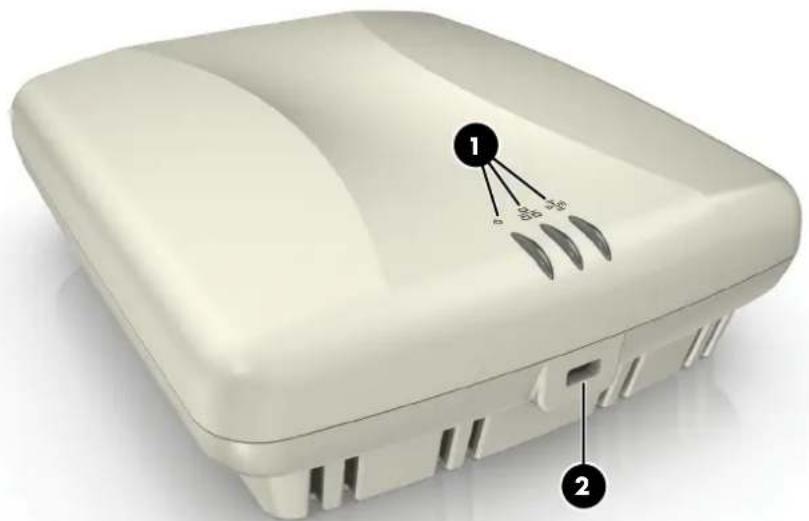
Front view
1: Status Lights (left to right) Power, Ethernet, Radio 2: Cable lock hole

Back view 3: Ethernet port1: Cable channel 4: Console port2: Mounting bracket tab slot
Status lights
The status lights provide different information depending on whether the AP is operating in autonomous mode or controlled mode. For more information on these modes, see "About mode and autonomous mode" (page 13).
Autonomous mode
In autonomous mode, the status lights indicate the following:
| DescriptionStateLight | ||
| The AP hasPower power.Off | ||
| On | The AP is fully operational. | |
| Blinking | The AP is starting up. If the Power light continues to blink after several that the software failed to load. Reset or power cycle the AP. If this contact HP Support. | |
| Ethernet | Toff port is not connected or there is no activity. | |
| Blinking | thg port is transmitting or receiving data. | |
| Radio | Blinking | thg radio is transmitting or receiving data. |
Controlled mode
During startup/discovery in controlled mode, the status lights indicate the following:
| Status light behavior | Description |
| Power light blinks every two seconds. | The AP is starting up. |
| Power light blinks once per second. | The AP is looking for an IP address, or build VLANs on which to perform controller discovery. management tool is available until discovery occDescriptionStatus light behavior |
| Power, Ethernet, and Radio, lights blink in sequence left to right. | Three AP has obtained an IP address and is attempting discover a controller. |
| Power light is on. Ethernet and Radio lights blink alternately. | The AP has found a controller and is attempting to use a secure management tunnel with it. |
| Power and Ethernet lights blink alternately and Radio lights are off. | Thickly AP has received a discovery reply from two or more controllers with the same priority setting. The AP is unable to connect with either controller until the conflict is rescaled. |
| Power and Radio lights blink slowly. | The AP is attempting to establish a local mesh master node. |
| The AP is attempting to establish wired connectivity. |
Once the discovery process is complete, and the AP has established a secure management connection to a controller, the Power light remains on and the Ethernet and Radio lights blink to indicate the presence of traffic.
Ports
- Ethernet port: Auto-sensing 10/100/1000 BaseT Ethernet port with an RJ-45 connector. The port supports Power over Ethernet (PoE) 802.3af.
- Console port: Standard console (serial) port with an RJ-45 connector. For details, see Console Ports in the MSM3xx / MSM4xx APs Configuration Guide. There is no need to use the Console port for initial configuration.

WARNING! Never connect the Console port to an Ethernet switch or PoE power source to avoid damaging the AP. Connect it only to other serial ports via an RJ-45 to serial port adapter.
Radio and antenna
The AP contains an integrated single 802.11n/a/b/g radio with an internal three-element, dual-band, MIMO antenna.
Reset button
The Reset button is accessible via a hole on the bottom of the AP, as identified by the clip under the cable and into the reset button hole at the precise angle shown.

1: Reset button hole
- Press and quickly release the button to reset the AP.
- To reset the AP to factory defaults, press the button until the status lights blink three times, then release. Following a reset to factory defaults, the AP starts up in controlled mode, with the option to switch it to autonomous mode.
Important information to read before installing
For indoor installation only.
Professional installation required
WARNING! Prior to installing or using the AP, consult with a professional installer trained in RF installation and knowledgeable in local regulations including building and wiring codes, such as channel, power, indoor/outdoor restrictions, and license requirements for the intended use. It is the responsibility of the end user to ensure that installation and use comply with local radio regulations.
Cabling
You must use the appropriate cables, and where applicable, surge protection, for your region. Cables with large boots may not insert into the RJ-45 connectors properly. It is recommended that you do not use such cables. Cat 5e (or better) cabling is required.
Plenum installation
The AP can be installed in a plenum (UL2043 rating). The AP is suitable for use in air space in accordance with Section 300-22(C) of the National Electrical Code, and Sections 2-128, 12-010(3), and 12-100 of the Canadian Electrical Code, Part 1, CSA C22.1.
The AP should be installed in a similar orientation as in a ceiling installation. However, a qualified installer should determine how to install and secure the AP in a plenum in an effective and safe manner. Plenum-rated cables and attachment hardware must be used.
Country of use
CAUTION: In some regions, you are prompted to select the country of use during setup. Once the country has been set, the AP will automatically limit the available wireless channels to ensure compliant operation in the selected country. Entering the incorrect country may result in non-compliant operation and may cause harmful interference to other systems.
Safety
Take note of the following safety information during installation.
- If your network covers an area served by more than one power distribution system, all safety grounds are securely interconnected.
- Network cables may occasionally be subject to hazardous transient voltages (caused by lightning or disturbances in the electrical power grid).
- Handle exposed metal components of the network with caution.
- The AP is powered-on when connected to a PoE power source.
- The AP and all interconnected equipment must be installed indoors within the same building, including all PoE-powered network connections as described by Environment A of the 802.3af standard.
2 Installation
The AP can be mounted on a wall, a wall-mounted electrical box, or a suspended ceiling. The first step is to mount the bracket, and the second step is to attach the AP.
Mounting directly on a wall
- Respecting the UP indicator on the bracket, hold the bracket against the wall at the desired position. Mark two holes for the screws (wall anchors) and one hole in the cutout of the bracket for the Ethernet cable.
- Drill two holes for the wall anchors, typically 4.7 mm (3/16 inch) in diameter.
- If necessary, drill a hole for the Ethernet cable in the marked cutout area of the bracket. Alternatively, you can feed the Ethernet cable from above and through the AP cable entry.
- Insert the anchors and tap them flush with the wall surface.
- If applicable, pull the Ethernet cable through the hole in the wall and the hole in the bracket.
- Screw the bracket to the wall.
- Continue with "Attaching the AP to the mounting bracket" (page 11).
Mounting on a wall-mounted electrical box
The AP can be mounted on a wall-mounted electrical box using the supplied mounting bracket.
- Disconnect power and take any other needed safety precautions.

1: Retention tabs 2: Mounting holes for electrical box 3: UP indicator
- Remove the electrical box cover and any contents.
- Pull the Ethernet cable down into the box and then through the hole in the bracket.
- Hold the bracket against the box respecting the UP indicator and attach the bracket to the box using appropriate countersunk screws.
- Continue with "Attaching the AP to the mounting bracket" (page 11).
Mounting on a suspended ceiling
The AP can be mounted on a suspended ceiling using the mounting bracket (supplied clips (supplied only with rev B US J9426B and WW J9427B).
- For ease of assembly, pre-position the two T-bar clips on the bracket as illustrated, clip posts in the holes of the bracket until the posts can move freely. Remove bracket.

1: T-bar clip
2: Smooth side of bracket
- Install the clips on the suspended ceiling T-bar at the desired mounting position, 1/8 inches apart on center.
- Mount the bracket on the clips, and secure with a nut on each clip. The smooth side of the bracket must be facing the clips.
- Once the bracket is firmly attached to the T-bar, cut a hole in the ceiling through the opening for the Ethernet cable.
- Run the Ethernet cable to the hole and then pull the cable through the hole in the ceiling.
Attaching the AP to the mounting bracket
- Connect the Ethernet cable to the AP Ethernet port.
- Position the AP against the bracket so that the bracket tabs fit into the tab slots on the AP. Push the AP against the bracket and then slide the AP firmly so that it locks onto the bracket.
- Verify that the AP is firmly anchored before letting go of it.
- Optionally, secure the AP to an immovable object with a cable lock using the status lights.
Powering the AP
The AP can be powered by:
• A 10/100 or 10/100/1000 PoE-enabled switch. PoE-enabled switches are available from HP. • An HP 1-Port Power Injector (J9407A).
CAUTION: If the AP will be powered by a user-supplied PoE power injector, use only a gigabit-compatible power injector. PoE injectors designed only for 10/100 networks are not compatible with the AP.
CAUTION: When mounting the AP, ensure that the surface to which you attach the AP and the fasteners used support a weight of 1.1 kg (2.4 pounds). Allow extra weight for cables.
3 Initially Configuring (Autonomous mode)
About controlled mode and autonomous mode
The AP can operate in one of two modes: controlled (the default) or autonomous. Resets all configuration settings to factory defaults.
- Controlled mode: To become operational, the AP must establish a management tunnel with an MSM7xx Controller. The controller manages the AP and provides all configuration. Discovery of the controller is automatic if default settings are used on the AP and both devices are on the same subnet. See Working with controlled APs in the MSM7xx Controllers Configuration Guide.
- Autonomous mode: After being switched to autonomous mode, the AP operates as a stand-alone AP. You configure and manage an autonomous AP by using its Web-based management tool as described in "Initial configuration (autonomous mode)" (page 13).
Initial configuration (autonomous mode)
This procedure describes how to switch a factory-default AP to autonomous mode and its initial configuration that enables you to establish a wireless connection through the Internet.
In autonomous mode, the AP is managed via its Web-based management tool as a section. This requires at least Microsoft Internet Explorer 8+ or Mozilla Firefox 3+.
For controlled mode configuration, see Working with controlled APs in the MSM7xx Controllers Configuration Guide.
CAUTION: Wireless protection: A factory-default AP that has been switched to autonomous mode has wireless protection options disabled. It is recommended that after initial configuration, enable a wireless security option to properly safeguard the wireless network from intruders. See Wireless protection in the MSM3xx / MSM4xx APs Configuration Guide.
NOTE: Do not power-on the AP until directed.
Step 1: Configure your computer
- Disconnect your computer LAN port and configure it to use a static IP address 192.168.1.2 to 192.168.1.254, and a subnet mask of 255.255.255.0. Set the default gateway to 192.168.1.1, and DNS server to 192.168.1.1.
- Disable any wireless connection on your computer.
Step 2: Connect the cables and power on the AP
- Connect the cables:
- If using a PoE switch, use Ethernet cables to connect your computer and the unused factory-default PoE switch.
- If using a PoE injector, use Ethernet cables to connect your computer to the data port on the PoE injector and the AP to the data and power-out port on the PoE injector.
- Power on the AP by powering on the PoE switch or injector.
- Initially, the AP power light will blink once every two seconds. Wait approximately one minute until it begins blinking once per second before proceeding to the next step.
Step 3: Switch the AP to autonomous mode
NOTE: A factory-default AP is assumed.
- In a Web browser, enter the address: https://192.168.1.1.
- A security certificate warning is displayed the first time you connect to the manager. This is normal. Select whatever option is needed in your Web browser to continue to the management tool.
- On the Login page, specify admin for both Username and Password, and then select Login. The management tool home page opens.
- Select Switch to Autonomous Mode and confirm the change. The AP restarts in autonomous mode.
NOTE: To avoid a delay after switching modes, clear the ARP (address resolution protocol) cache on your computer. In Windows for example, from the Windows Start menu, select Run and enter "arp -d" (without the quotes). Select OK.
Step 4: Log in
- Wait until the Power light stops blinking and remains on.
- On the Login page, specify admin for both Username and Password, and then select Login.
- Click through the prompts for License and Registration.
- In some regions, a Country prompt appears. Select the country in which the AP is used. The correct country must be selected. See "Country of use" (page 8).
- At the password prompt it is recommended that you change the default password of Save. New passwords must be at least six characters long and include four different character types.
The management tool is organized with menus and sub-menus. Instructions for making selections, such as "select Wireless > Local mesh" instruct you to select the Wireless menu and then the Local mesh sub-menu, as follows:

Step 5: Configure basic wireless protection
It is recommended that you at least configure basic wireless protection. See Wireless protection in the MSM3xx / MSM4xx APs Configuration Guide. To configure basic WPA protection:
- Select VSC > HP and then enable Wireless protection and set it to WPA.
- Under Mode, select WPA or WPA2, then under Key source, select Preshared key and specify a key of at least 20 characters. Select Save.
Step 6: Assign an IP address to the AP
By default, the AP operates as a DHCP client. This means that if the network has a DHCP server, the AP will automatically receive a new IP address in place of its default address of 192.168.1.1
upon connecting to the network. Use one of the following methods to assign an IP address to the AP:
- Pre-configure the DHCP server to assign a specific IP address to the AP. To do this, you need to specify the AP Ethernet MAC address and a reserved IP address on the DHCP server. The AP Ethernet MAC address is printed on the AP label, identified as Ethernet Base MAC, and is also listed on the management tool Home page as Ethernet base MAC address.
- Let the DHCP server automatically assign an IP address. By default, the DHCP server will assign an IP address once the AP connects to the network. Once the DHCP server has assigned an IP address to the AP, you can find the IP address of the AP by looking for the
base MAC address in the DHCP server log. For example, after sub-step 4 below, go to the DHCP server log to retrieve the IP address assigned to the AP.
- Assign a static IP address to the AP. The address must be on the same subnet as the network to which the AP will connect.
- Select Network > DNS, and set the DNS server address. Select Save.
- Select Network > Ports > Bridge port.
- Select Static and then Configure. Configure settings as follows:
- IP address: Set an address that is on the same subnet as the network to which the AP will connect once installed. Respect any DHCP server-mandated static IP ranges.
- Mask: Set the corresponding mask for the IP address.
- Default gateway: Set the IP address of the gateway on the network.
- Select Save. Connection to the management tool is lost.
Step 7: Test the wireless network
For the purposes of this example, the network must have a DHCP server and a broadband router typically includes a DHCP server.
- Disconnect your computer from the PoE switch or injector.
- Power off the AP by disconnecting the Ethernet cable from the AP.
- Use a standard Ethernet cable to connect the switch or the data in port of the network.
- Reconnect and power on the AP. Use a standard Ethernet cable to reconnect the PoE switch or the data and power-out port of the injector.
- Enable the wireless network interface on your computer, and verify that it is set to obtain an IP address automatically.
- By default, the AP creates a wireless network named HP. Connect your computer to this wireless network, specifying the preshared key you set earlier in "Step 5: Configure basic protection" (page 14).
- Confirm that you can browse the Internet using the wireless network.
Step 8: Perform additional configuration
Configure your computer LAN port and connect it to the same network as the AP. AP management tool at https:// where is the AP IP address from "Step
6: Assign an IP address to the AP" (page 14).
To enable access to other resources
By default, the AP only permits traffic that is addressed to the default gateway on (which enables you to connect to the Internet). To enable access to other resources:
- Select VSC > Profiles and then select the HP profile.
- On the Add/Edit Virtual Service Community page clear the Wireless security filters checkbox.
- Select Save.
4 Support and other resources
Online Documentation
You can download documentation from the HP Support Website at: www.hp.com/support/manuals. Search by product number or name.
Contacting HP
For worldwide technical support information, see the HP support Website: www.hp.com/networking/support
Before contacting HP, collect the following information:
• Product model names and numbers • Technical support registration number (if applicable) • Product serial numbers • Error messages • Operating system type and revision level • Detailed questions
HP Websites
For additional information, see the following HP Websites:
• www.hp.com/networking • www.hp.com
Typographic conventions
Table 1 Document conventions
| ElementConvention | |
| Cross-reference links and e-mail addressesBlue text: | |
| Website addressesBlue, underlined text: www.hp.co | |
| Bold text | Keys that are pressedText typed into a GUI element, such as aGUI elements that are clicked or selected, such as menuand list items, buttons, tabs, and check boxes |
Table 1 (page 16)
WARNING! Indicates that failure to follow directions could result in bodily harm or death.
CAUTION: Indicates that failure to follow directions could result in damage to equipment or data.
IMPORTANT: Provides clarifying information or specific instructions.
NOTE: Provides additional information.
TIP: Provides helpful hints and shortcuts.
A Regulatory information
Notice for U.S.A.
Manufacturer's FCC Declaration of Conformity statement
| Hewlett-Packard CompanyManufacturer:3000 Hanover StreetPalo Alto, CA 94304-1185 USA |
For questions regarding this declaration, contact the Product Regulations Manager at the address.
FCC Class A statement
This is an FCC Class A device. In a domestic environment this product may cause interference, in which case the user may be required to take adequate measures. This equipment has been tested and found to comply with the limits for a Class A digital device, pursuant to FCC Rules. These limits are designed to provide reasonable protection against harmful interference when the equipment is operated in a commercial environment. This equipment generates, uses, and can radiate radio frequency energy and, if not installed and used in accordance with the instruction manual, may cause harmful interference to radio communications. Operation of this equipment in a residential area is likely to cause harmful interference, in which case the user will be required to correct the interference at their own expense.
Notice to professional installers
As a Professional Installer responsible for the proper installation and configuration of Point, you need to understand and prepare for operating near any TDWR (Terminal Doppler Weather Radar) locations. The FCC has requested that you become familiar with and follow the following:
- Read and understand the FCC Memorandum dated July 27th, 2010, Subject: Eliminating interference to Terminal Doppler Weather Radar (TDWR) located here: www.spectrumbridge.com/Libraries/Misc_docs/FCC Memorandum on UNII Device Operation.sflb.ashx
- If the AP system is within the specified range of 35 km (21.75 mi) of any TDWR, set the primary transmit frequency (and alternate frequencies, if used) to a frequency (or frequencies) at least 30 MHz (center-to-center) from the TDWR operation frequency shown on www.spectrumbridge.com/udia/search.aspx, or in the table shown in the above FCC Memorandum.
- If you are using automatic channel assignment, add the channels you need to avoid to the automatic channel exclusion list.
- Register each AP system operating within 35 km (21.75 mi) of any TDWR in the voluntary WISPA-sponsored database at: www.spectrumbridge.com/udia/home.aspx
Exposure to radio frequency energy

WARNING! Although the radiated output power of this device is below the FCC radio exposure limits, the device should be used in such a manner that the potential for human contact with the antennas during normal operation is minimized. To avoid the possibility of exceeding radio frequency exposure limits, human proximity to the antennas should not be less than 20 cm (8 inches) during normal operation.
Notice for Canada
The following notices apply to Canada:
- This device complies with the limits for a Class B digital device and conforms to Industry Canada standard ICES-003. Products that contain a radio transmitter comply with Industry Canada standard RSS210 and are labeled with an IC approval number.
- This Class B digital apparatus complies with Canadian ICES-003. The wireless radio of this device complies with RSS 210 certification from Industry Canada and is labeled with an IC approval number.
- This device complies with the Class B limits of Industry Canada. Operation is subject to the following two conditions: 1) this device may not cause harmful interference, and 2) this device must accept any interference received, including interference that may cause undesired operation. To reduce potential radio interference with other users, the antenna type and its gain are chosen so that the equivalent isotropically radiated power (EIRP) is not more than that required for successful communication.
Notice for the European Community
CE
This device complies with the EMC Directive 2004/108/EC, Low Voltage Directive 2006/95/EC, and R&TTE Directive 1999/5/EC. Compliance with these directives implies conformity to harmonized European standards (European Norms) that are listed on the EU Declaration of Conformity issued by HP for this device.
Countries of operation & conditions of use
This device may be used in the following EU and EFTA countries: Austria, Belgium, Bulgaria, Cyprus, Czech Republic, Denmark, Estonia, Finland, France, Germany, Greece, Hungary, Iceland, Ireland, Italy, Latvia, Liechtenstein, Lithuania, Luxembourg, Malta, Netherlands, Norway, Poland, Portugal, Romania, Slovakia, Slovenia, Spain, Sweden, Switzerland, and the United Kingdom. Requirements for outdoor vs. indoor operation, licensing, and allowed channels of operation in some countries are described below.
NOTE: The user must use the configuration utility provided with this device to ensure the channels of operation are in conformance with the spectrum usage rules for EU and EFTA countries described below.
2.4 GHz operation
- This device requires the user or installer to properly enter the current country of operation in the 5 GHz Radio Configuration Window.
- This device will automatically limit the allowable channels determined by the current country of operation. Incorrectly entering the country of operation may result in illegal operation and may cause harmful interference to other systems. The user is obligated to ensure operation according to the channel limitations, outdoor/indoor restrictions, and license requirements for each European Community country as described in this guide.
- This device employs a radar detection feature required for European Community and EFTA country operation in the 5 GHz band. This feature is automatically enabled when operation is correctly configured for any European Community or EFTA country. Detection of nearby radar operation may result in temporary interruption of operation of the device. The radar detection feature will automatically restart operation on a channel free of radar.
- This device is restricted to indoor use when operated in EU and EFTA countries using the 5.15-5.35 GHz band (Channels 36, 40, 44, 48, 52, 56, 60 and 64). See the table for the allowed 5 GHz channels in each band.
Operation using 5 GHz channels in the European Community
The user/installer must use the provided configuration utility to check the current channel and make necessary configuration changes to ensure operation occurs in conformance with European National spectrum usage laws as described below and elsewhere in this guide.
| Maximum EIRP (mW)Usag | |||
| 5150 - 5250 | 36, 40, 44, 48 | Indoor use only | 200 |
| 5250 - 5350 | 52, 56, 60, 64 | 200Indoor use only | |
| 5470 - 5725 | 100, 104, 108, 112, 116, 132, 136, 140. | Indoor or outdoor use | 1000 |
Allowed
DGT LPD (Low Power Device) statement
Low-power radio-frequency devices management regulations
Turkish recycling notice
Vietnamese Information Technology and Communications compliance marking
B Recycle statements
Waste Electrical and Electronic Equipment (WEEE) statements
English recycling notice
Disposal of waste equipment by users in private household in the European Union

This symbol means do not dispose of your product with your other household waste. Instead, protect human health and the environment by handing over your waste equipment to a designated collection point for the recycling of waste electrical and electronic equipment. For more info please contact your household waste disposal service.
Bulgarian recycling notice
Czech recycling notice
Danish recycling notice
Dutch recycling notice
Estonian recycling notice
Finnish recycling notice
French recycling notice
German recycling notice
Greek recycling notice
Hungarian recycling notice
Italian recycling notice
Latvian recycling notice
Lithuanian recycling notice
Polish recycling notice
Portuguese recycling notice
Romanian recycling notice
Slovak recycling notice
Spanish recycling notice
Swedish recycling notice

- HP MSM410 802.11N AP INSTALLATION
- ABSTRACT
- ACKNOWLEDGMENTS
- WARRANTY
- CONTENTS
- PREPARING FOR INSTALLATION
- INSTALLATION
- INITIALLY CONFIGURING (AUTONOMOUS MODE)
- SUPPORT AND OTHER RESOURCES
- A REGULATORY INFORMATION
- B RECYCLE STATEMENTS
- PACKAGE CONTENTS
- IDENTIFYING AP COMPONENTS
- FRONT VIEW
- STATUS LIGHTS
- AUTONOMOUS MODE
- CONTROLLED MODE
- PORTS
- RADIO AND ANTENNA
- RESET BUTTON
- IMPORTANT INFORMATION TO READ BEFORE INSTALLING
- PROFESSIONAL INSTALLATION REQUIRED
- CABLING
- PLENUM INSTALLATION
- COUNTRY OF USE
- SAFETY
- MOUNTING DIRECTLY ON A WALL
- MOUNTING ON A WALL-MOUNTED ELECTRICAL BOX
- MOUNTING ON A SUSPENDED CEILING
- ATTACHING THE AP TO THE MOUNTING BRACKET
- POWERING THE AP
- ABOUT CONTROLLED MODE AND AUTONOMOUS MODE
- INITIAL CONFIGURATION (AUTONOMOUS MODE)
- STEP 1: CONFIGURE YOUR COMPUTER
- STEP 2: CONNECT THE CABLES AND POWER ON THE AP
- STEP 3: SWITCH THE AP TO AUTONOMOUS MODE
- STEP 4: LOG IN
- STEP 5: CONFIGURE BASIC WIRELESS PROTECTION
- STEP 6: ASSIGN AN IP ADDRESS TO THE AP
- STEP 7: TEST THE WIRELESS NETWORK
- STEP 8: PERFORM ADDITIONAL CONFIGURATION
- TO ENABLE ACCESS TO OTHER RESOURCES
- ONLINE DOCUMENTATION
- CONTACTING HP
- HP WEBSITES
- TYPOGRAPHIC CONVENTIONS
- FCC CLASS A STATEMENT
- NOTICE TO PROFESSIONAL INSTALLERS
- EXPOSURE TO RADIO FREQUENCY ENERGY
- NOTICE FOR CANADA
- NOTICE FOR THE EUROPEAN COMMUNITY
- CE
- COUNTRIES OF OPERATION & CONDITIONS OF USE
- GHZ OPERATION
- OPERATION USING 5 GHZ CHANNELS IN THE EUROPEAN COMMUNITY
- DGT LPD (LOW POWER DEVICE) STATEMENT
- TURKISH RECYCLING NOTICE
- ESTONIAN RECYCLING NOTICE
- FINNISH RECYCLING NOTICE
- FRENCH RECYCLING NOTICE
- GERMAN RECYCLING NOTICE
- GREEK RECYCLING NOTICE
- HUNGARIAN RECYCLING NOTICE
- ITALIAN RECYCLING NOTICE
- LATVIAN RECYCLING NOTICE
- LITHUANIAN RECYCLING NOTICE
- POLISH RECYCLING NOTICE
- PORTUGUESE RECYCLING NOTICE
- ROMANIAN RECYCLING NOTICE
- SLOVAK RECYCLING NOTICE
- SPANISH RECYCLING NOTICE
- SWEDISH RECYCLING NOTICE
Brand : HP
Model : ProCurve MSM410
Category : Access Point