
8S651M-RZ - Motherboard GIGABYTE - Free user manual and instructions
Find the device manual for free 8S651M-RZ GIGABYTE in PDF.

| Product type | Micro ATX Motherboard |
| Form factor | Micro ATX, 4-layer PCB |
| Dimensions | 24.4 cm x 21.5 cm |
| Chipset | North Bridge SiS 651, South Bridge SiS 962L |
| CPU Socket | Socket 478 for Intel Pentium 4 |
| CPU Support | Intel Pentium 4 (Northwood, 0.13 µm) FSB 400/533 MHz |
| Memory | 2 x DDR DIMM, DDR200/266/333, up to 2 GB max. |
| Expansion Slots | 1 AGP 2X/4X, 3 PCI 33 MHz |
| Storage | 2 x IDE (UDMA 33/66/100/133), 1 x Floppy |
| Rear Ports | 1 PS/2 keyboard, 1 PS/2 mouse, 1 parallel, 1 serial, 1 VGA, 2 USB 2.0, 1 LAN RJ-45, 3 audio (Line out, Line in, Mic), 1 Game/MIDI |
| Additional USB | 4 front USB 2.0 ports (via cables) |
| Audio | Realtek ALC655, 2/4/6 channels, SPDIF In/Out |
| Network | RTL8201 10/100 Mb/s (model 8S651M-RZ) |
| BIOS | Award BIOS, Q-Flash support |
| Required Power Supply | 20-pin ATX connector + 4-pin ATX 12V connector |
| Special Features | PS/2 keyboard/mouse power-on, STR (Suspend to RAM), AC Recovery, EasyTune 4, @BIOS |
| Hardware Monitoring | CPU/system temperature detection, fan speeds, voltages |
| Security | Electrostatic discharge protection, chassis intrusion detection, BIOS password |
| Maintenance and Cleaning | Disconnect power before intervention, use an antistatic wrist strap, clean with a dry cloth |
| Spare Parts and Repairability | Replaceable CMOS battery (CR2032), replaceable memory and CPU |
Frequently Asked Questions - 8S651M-RZ GIGABYTE
User questions about 8S651M-RZ GIGABYTE
0 question about this device. Answer the ones you know or ask your own.
Ask a new question about this device
Download the instructions for your Motherboard in PDF format for free! Find your manual 8S651M-RZ - GIGABYTE and take your electronic device back in hand. On this page are published all the documents necessary for the use of your device. 8S651M-RZ by GIGABYTE.
USER MANUAL 8S651M-RZ GIGABYTE
©2003GIGABYTECHNOLOGYCO.,LTD
CopyrightbyGIGA-BYTETECHNOLOGYCO.,LTD.("GBT").No part of this manual may be reproduced or transmitted in any from without the expressed, written permission of GBT.
Trademarks
Third-party brands and names are the property of their respective owners.
Notice
Please do not remove any labels on motherboard, this may void the warranty of this motherboard.
Due to rapid change in technology, some of the specifications might be out of date before publication of this booklet.
The author assumes no responsibility for any errors or omissions that may appear in this document nor does the author make a commitment to update the information contained herein.

Preparing Your Computer
Computer motherboards and expansion cards contain very delicate Integrated Circuit (IC) chips. To protect them against damage from static electricity, you should follow some precautions whenever you work on your computer.
- Unplug your computer when working on the inside.
- Use a grounded wrist strap before handling computer components. If you do not have one, touch both of your hands to a safely grounded object or to a metal object, such as the power supply case.
- Hold components by the edges and try not touch the IC chips, leads or connectors, or other components.
- Place components on a grounded antistatic pad or on the bag that came with the components whenever the components are separated from the system.
- Ensure that the ATX power supply is switched off before you plug in or remove the ATX power connector on the motherboard.

Installing the motherboard to the chassis
If the motherboard has mounting holes, but they don't line up with the holes on the base and there are no slots to attach the spacers, do not become alarmed you can still attach the spacers to the mounting holes. Just cut the bottom portion of the spacers (the spacer maybe a little hard to cutoff, so be careful of your hands). In this way you can still attach the motherboard to the base without worrying about short circuits. Sometimes you may need to use the plastic springs to isolate the screw from the motherboard PCB surface, because the circuit wire may be near by the hole. Be careful, don't let the screw contact any printed circuit write or parts on the PCB that are near the fixing hole, otherwise it may damage the board or cause board malfunctioning.
Table of Content
Chapter 1 Introduction 5
FeaturesSummary 5
8S651M-RZ Series Motherboard Layout 7
Block Diagram 8
Hardware Installation Process 9
Step 1: Install the Central Processing Unit (CPU)
Step 1-1: CPU Installation 10
Step 1-2: CPU Cooling Fan Installation 10
Step 2: Install memory modules 11
Step 3: Install expansion cards 12
Step 4: Install I/O Peripherals Cables 12
Step 4-1: I/O Back Panel Introduction 12
Step 4-2: Connectors Introduction 13
Chapter 2 BIOS Setup 21
The Main Menu (For example: BIOS Ver.: E4) 21
Standard CMOS Features 23
Advanced BIOS Features 25
Integrated Peripherals 26
PowerManagementSetup 28
PhP/PCl Configurations 30
PCI Health Status 31
Frequency/Voltage Control 32
Top Performance 33
Load Fail-Safe Defaults 33
Load Optimized Defaults 34
Set Supervisor/User Password 34
Save & Exit Setup 35
Exit Without Saving 35
Chapter 3 Driver Installation 36
Chapter 1 Introduction
Features Summary
| CPU | • Socket 478 for Intel® Micro FC-PGA2 Pentium® 4 processor • Support Intel® Pentium® 4 (Northwood, 0.13μm) processor • Intel Pentium® 4 400/533 MHz FSB • 2nd cache depends on CPU |
| Chipset | • North Bridge:SiS 651 • South Bridge:SiS 962L MuTIOL Media I/O |
| Memory | • 2 184-pin DDR sockets • Supports DDR200/DDR266/DDR333 • Supports up to 2 un-buffer Double-sided DIMM DDR200/266 /333 • Supports up to 2GB (Max) • Supports only 2.5V DDR DIMM |
| Slots | • 1 Universal AGP slot (2X/4X) device support • 3 PCI slot supports 33MHz & PCI 2.2 compliant |
| On-Board IDE | • 2 IDE bus master (UDMA33/ATA66/ATA100/ATA133) IDE ports for up to 4 ATAPI devices • Supports PIO mode3,4 (UDMA 33/ATA66/ATA100/ATA133) IDE & ATAPI CD-ROM |
| On-Board Floppy | • Floppy port supports 2 FDD with 360K, 720K,1.2M, 1.44M and 2.88M bytes |
| On-Board Peripherals | • 1 Parallel port supports Normal/EPP/ECP mode • 1 Serial port (COMA),1 VGA port,COMB on board • 6 x USB 2.0/1.1 (2 x Rear, 4 xFront by cable) • 1 Front Audio Connector • 1 IRDA connector for IR • PS/2 Keyboard interface and PS/2 Mouse interface |
| On-Board VGA | • Build in SiS651 Chipset |
| On-Board LAN * | • Build in RTL8201 Chipset |
| On-Board Sound | • Realtek ALC655 CODEC • Line Out / 2 front speaker • Line In / 2 rear speaker(by s/w switch) • Mic In / center& subwoofer(by s/w switch) • SPDIF Out /SPDIF In • CD_In / Game Port |
| BIOS | • Licensed Award BIOS • Supports Q-Flash |
| I/O Control | • W83697HF |
"For 8S651M-RZ only.
| Hardware Monitor | • CPU/System Fan Revolution detect • CPU/System Fan Control • CPU Overheat Warning • System Voltage Detect |
| Additional Features | • PS/2 Keyboard power on by password • PS/2 Mouse power on • STR(Suspend-To-RAM) • AC Recovery • USB KB/Mouse wake up from S3 • Supports EasyTune 4 • Supports @BIOS |
| Form Factor | • 24.4cm x 21.5cm Micro ATX size form factor, 4 layers PCB. |

Please set the CPU host frequency in accordance with your processor's specifications. We don't recommend you to set the system bus frequency over the CPU's specification because these specific bus frequencies are not the standard specifications for CPU, chipset and most of the peripherals. Whether your system can run under these specific bus frequencies properly will depend on your hardware configurations, including CPU, Chipsets, Memory, Cards....etc.
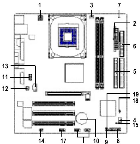
8S651M-RZ Series Motherboard Layout
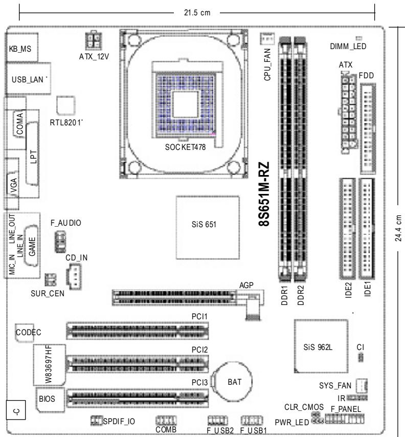
*For 8S651M-RZ only.
Block Diagram
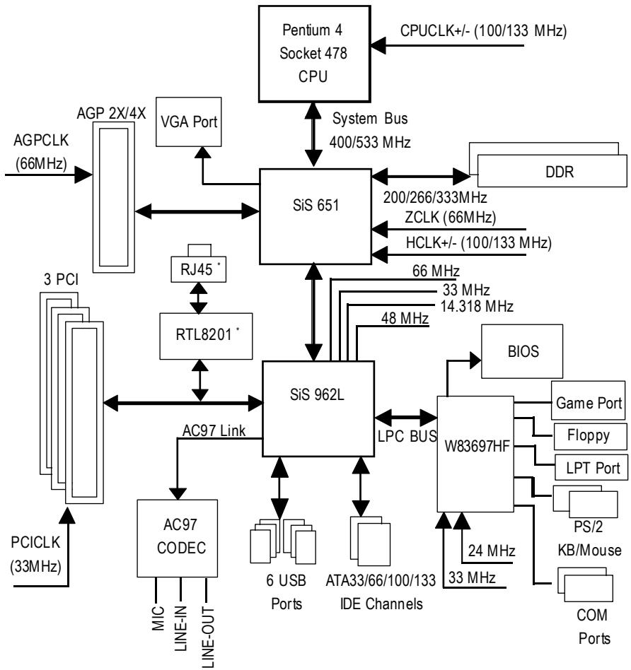
*For 8S651M-RZ only.
Hardware Installation Process
To set up your computer, you must complete the following steps:
Step 1- Install the Central Processing Unit (CPU)
Step 2- Install memory modules
Step 3- Install expansion cards
Step 4- Install I/O Peripherals cables
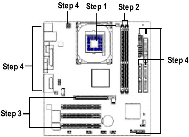
Step 1: Install the Central Processing Unit (CPU)

Before installing the processor, adhere to the following warning:
- Please make sure the CPU type is supported by the motherboard.
- The processor will overheat without the heatsink and/or fan, resulting in permanent irreparable damage.
- If you do not match the CPU socket Pin 1 and CPU cut edge well, it will cause improper installation. Please change the insert orientation.
- Apply thermal grease between the processor and cooling fan.
- Never run the processor without the heatsink properly and firmly attached. Permanent damage will result.
- Please set the CPU host frequency in accordance with your processor's specifications. We don't recommend you to set the system bus frequency over the CPU's specification because these specific bus frequencies are not the standard specifications for CPU, chipset and most of the peripherals. Whether your system can run under these specific bus frequencies properly will depend on your hardware configurations, including CPU, Memory, Cards...etc.

HT functionality requirement content :
Enabling the functionality of Hyper-Threading Technology for your computer system requires all of the following platform components:
- CPU: An Intel Pentium 4 Processor with HT Technology
- Chipset An Intel® Chipset that supports HT Technology
- BIOS: A BIOS that supports HT Technology and has it enabled
- OS: An operation system that has optimizations for HT Technology
Step 1-1: CPU Installation
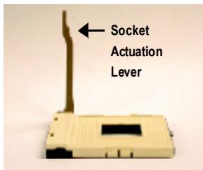
Figure 1. Pull the rod to the 90-degree directly.
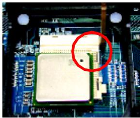
Figure 2. Locate Pin 1 in the socket and look for a (golden) cut edge on the CPU upper corner. Insert the CPU into the socket. (Do not force the CPU into the socket.) Then move the socket lever to the locked position while holding pressure on the center of the CPU.
Step 1-2: CPU Cooling Fan Installation
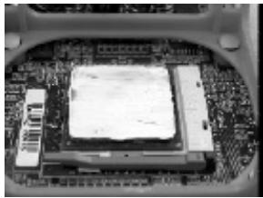
Figure 1. Apply the thermal tape (or grease) to provide better heat conduction between your CPU and cooling fan.
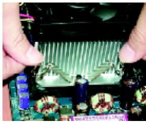
Figure 2.
Fasten the cooling fan supporting-base onto the CPU socket on the motherboard.
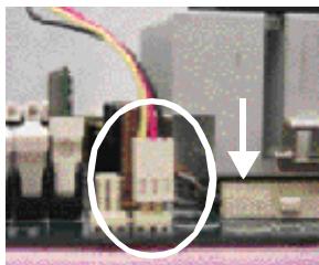
Figure 3. Make sure the CPU fan is plugged to the CPU fan connector, than install complete.
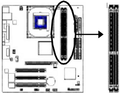
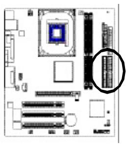
Step 2: Install memory modules

Before installing the memory modules, adhere to the following warning:
- When DIMM LED is ON, do not install / remove DIMM from socket.
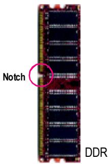
- Please note that the DIMM module can only fit in one direction due to the one notch. Wrong orientation will cause improper installation. Please change the insert orientation.
The motherboard has 2 dual inline memory module (DIMM) sockets. The BIOS will automatically detects memory type and size. To install the memory module, just push it vertically into the DIMM socket. The DIMM module can only fit in one direction due to the notch. Memory size can vary between sockets.
Support Unbuffered DDR DIMM Sizes type:
| 64 Mbit (2Mx8x4 banks) | 64 Mbit (1Mx16x4 banks) | 128 Mbit (4Mx8x4 banks) |
| 128 Mbit (2Mx16x4 banks) | 256 Mbit (8Mx8x4 banks) | 256 Mbit (4Mx16x4 banks) |
| 512 Mbit (16Mx8x4 banks) | 512 Mbit (8Mx16x4 banks) |
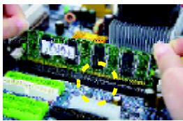
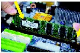
- The DIMM socket has a notch, so the DIMM memory module can only fit in one direction.
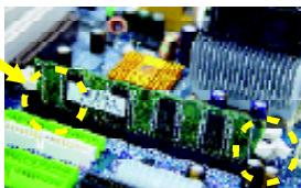
- Insert the DIMM memory module vertically into the DIMM socket. Then push it down.
- Close the plastic clip at both edges of the DIMM sockets to lock the DIMM module.
Reverse the installation steps when you wish to remove the DIMM module.
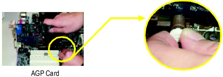
Step 3: Install expansion cards
- Read the related expansion card's instruction document before install the expansion card into the computer.
- Please make sure your AGP card is AGP 4X/8X (1.5V).
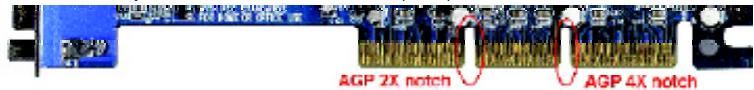
- Please carefully pull out the small white- drawable bar at the end of the AGP slot when you try to install/ Uninstall the AGP card. Please align the AGP card to the onboard AGP slot and press firmly down on the slot .Make sure your AGP card is locked by the small white- drawable bar.
Step 4: Install I/O Peripherals Cables
Step 4-1: I/O Back Panel Introduction
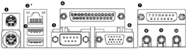
PS/2 Keyboard and PS/2 Mouse connector
This connector supports standard PS/2 keyboard and PS/2 mouse.
LAN port*
LAN is fast Ethernet with 10/100M bps speed.
USB port
Before you connect your device(s) into USB connector(s), please make sure your device(s) such as USB keyboard, mouse, scanner, zip, speaker...etc. Have a standard USB interface. Also make sure your OS supports USB controller. If your OS does not support USB controller, please contact OS vendor for possible patch or driver upgrade. For more information please contact your OS or device(s) vendors.
4 Parallel port (LPT)
Device like printer can be connected to Parallel port.
Serial port (COMA)
Mouse and modem etc. can be connected to Serial port.
"For 8S651M-RZ only.
VGA port
Monitor can be connected to VGA port.
Game/MIDlport
This connector supports joystick, MIDI keyboard and other relate audio devices.
Line Outjack
Connect the stereo speakers or earphone to this connector.
Line In jack
Devices like CD-ROM, walkman etc. can be connect to Line In jack.
MIC Injack
Microphone can be connect to MIC In jack.
After installation of the audio driver, you are able to use 2/4/6-channel audio feature by software selection. You can connect "Front speaker" to "Line Out" jack, Connect "Rear speaker" to "Line In" jack and connect "Center/Subwoofer" to "MIC In" jack.
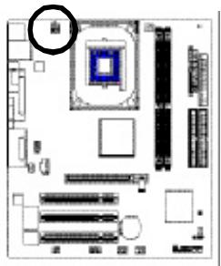
Step 4-2: Connectors Introduction
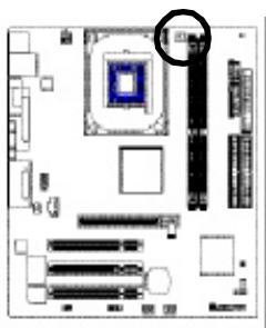
This connector (ATX_12V) supplies the CPU operation voltage (Vcore). If this "ATX_12V connector" is not connected, system cannot boot.

| PinNo. | Definition |
| 1 | GND |
| 2 | GND |
| 3 | +12V |
| 4 | +12V |
2)ATX (ATX Power)
AC power cord should only be connected to your power supply unit after ATX power cable and other related devices are firmly connected to the mainboard.
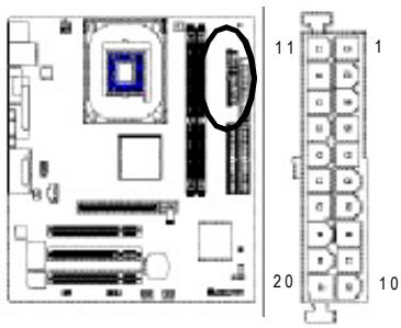
| Pin No. | Definition | Pin No. | Definition |
| 1 | 3.3V | 11 | 3.3V |
| 2 | 3.3V | 12 | -12V |
| 3 | GND | 13 | GND |
| 4 | VCC | 14 | PS_ON(soft on/off) |
| 5 | GND | 15 | GND |
| 6 | VCC | 16 | GND |
| 7 | GND | 17 | GND |
| 8 | Power Good | 18 | -5V |
| 9 | 5V SB(stand by +5V) | 19 | VCC |
| 10 | +12V | 20 | VCC |
3) CPU_FAN(CPU FAN Connector)
Please note, a proper installation of the CPU cooler is essential to prevent the CPU from running under abnormal condition or damaged by overheating. The CPU fan connector supports Max. current up to 600mA .

| PinNo. | Definition |
| 1 | GND |
| 2 | +12V |
| 3 | Sense |
4) SYS_FAN(System FAN Connector)
This connector allows you to link with the cooling fan on the system case to lower the system temperature.

| Pin No. | Definition |
| 1 | GND |
| 2 | +12V |
| 3 | Sense |
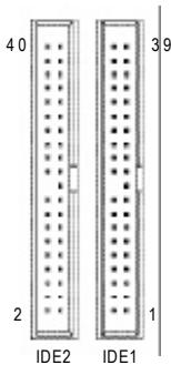
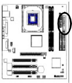
5) IDE1/IDE2(IDE1/IDE2 Connector)
Please connect first harddisk to IDE1 and connect CDROM to IDE2.
The red stripe of the ribbon cable must be the same side with the Pin1.
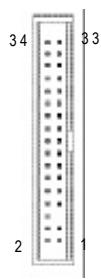
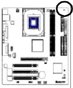
Please connect the floppy drive ribbon cables to FDD. It supports 360K,720K,1.2M,1.44M and 2.88M bytes floppy disk types.
The red stripe of the ribbon cable must be the same side with the Pin1.
7) DIMM_LED
Do not remove memory modules while DIMM LED is on. It might cause short or other unexpected damages due to the 2.5V stand by voltage. Remove memory modules only when AC Power cord is disconnected.

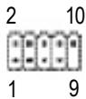
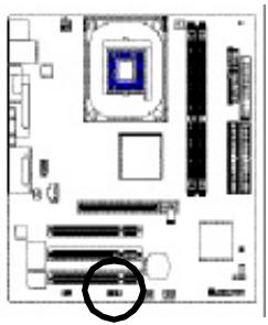
8) F PANEL (2x10 pins connector)
Please connect the power LED, PC peaker, reset switch and power switch etc of your chassis front panel to the F PANEL connector according to the pin assignment above.
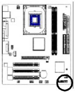
| HD (IDE Hard Disk Active LED) | Pin 1:LED anode(+) Pin 2:LED cathode(-) |
| SPK(SpeakerConnector) | Pin1:VCC(+) Pin2-Pin 3:NC Pin4:Data(-) |
| RST (ResetSwitch) | Open:NormalOperation Close:ResetHardware System |
| PW(SoftPower Connector) | Open:NormalOperation Close:Power On/Off |
| MPD的消息LED/Power/ SleepLED) | Pin 1:LED anode(+) Pin 2:LED cathode(-) |
| NC | NC |
9)PWR_LED
PWR_LED is connect with the system power indicator to indicate whether the system is on/off. It will blink when the system enters suspend mode. If you use dual color LED, power LED will turn to another color.
1
| Pin No. | Definition |
| 1 | MPD+ |
| 2 | MPD- |
| 3 | MPD- |
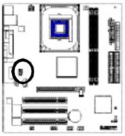
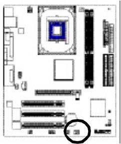
10) BAT (Battery)
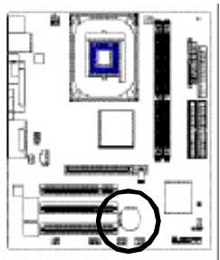
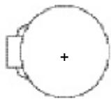
CAUTION
Danger of explosion if battery is incorrectly replaced.
Replace only with the same or equivalent type recommended by the manufacturer.
Dispose of used batteries according to the manufacturer's instructions.
If you want to erase CMOS...
- Turn OFF the computer and unplug the power cord.
- Remove the battery, wait for 30 second.
- Re-install the battery.
- Plug the power cord and turn ON the computer.
11) F=AUDIO (F=AUDIO Connector)
If you want to use Front Audio connector, you must remove 5-6, 9-10 Jumper. In order to utilize the front audio header, your chassis must have front audio connector. Also please make sure the pin assignment on the cable is the same as the pin assignment on the MB header. To find out if the chassis you are buying support front audio connector, please contact your dealer. Please note, you can have the alternative of using front audio connector or of using rear audio connector to play sound.

| Pin No. | Definition |
| 1 | MIC |
| 2 | GND |
| 3 | REF |
| 4 | POWER |
| 5 | FrontAudio(R) |
| 6 | RearAudio(R) |
| 7 | Reserved |
| 8 | NoPin |
| 9 | FrontAudio(L) |
| 10 | RearAudio(L) |
12) SUR_CEN
Please contact your nearest dealer for optional SUR_CEN cable.

| PinNo. | Definition |
| 1 | SUROUTL |
| 2 | SUROUTR |
| 3 | GND |
| 4 | NoPin |
| 5 | CENTER_OUT |
| 6 | BASS_OUT |
13) CD_IN
Connect CD-ROM or DVD-ROM audio out to the connector.
| PinNo. | Definition |
| 1 | CD-L |
| 2 | GND |
| 3 | GND |
| 4 | CD_R |
14) SPDIF_IO (SPDIF In/Out)
The SPDIF output is capable of providing digital audio to external speakers or compressed AC3 data to an external Dolby Digital Decoder. Use this feature only when your stereo system has digital input function. Use SPDIF IN feature only when your device has digital output function. Be careful with the polarity of the SPDIF_IO connector. Check the pin assignment carefully while you connect the SPDIF_IO cable, incorrect connection between the cable and connector will make the device unable to work or even damage it. For optional SPDIF_IO cable, please contact your local dealer.


| PinNo. | Definition |
| 1 | VCC |
| 2 | NoPin |
| 3 | SPDIF |
| 4 | SPDIFI |
| 5 | GND |
| 6 | GND |
15) IR
Make sure the pin 1 on the IR device is aling with pin one the connector. To enable the IR function on the board, you are required to purchase an option IR module. Be careful with the polarity of the IR connector. For optional IR cable, please contact your local dealer.


| PinNo. | Definition |
| 1 | VCC |
| 2 | NoPin |
| 3 | IRData Input |
| 4 | GND |
| 5 | IRData Output |
16) F_USB1 / F_USB2 (Front USB Connector)
Be careful with the polarity of the F_USB connector. Check the pin assignment carefully while you connect the F_USB cable, incorrect connection between the cable and connector will make the device unable to work or even damage it. For optional F_USB cable, please contact your local dealer.
| Pin No. | Definition |
| 1 | Power |
| 2 | Power |
| 3 | USBDX- |
| 4 | USBDy- |
| 5 | USBDX+ |
| 6 | USBDy+ |
| 7 | GND |
| 8 | GND |
| 9 | NoPin |
| 10 | NC |
Be careful with the polarity of the COMB connector. Check the pin assignment while you connect the COMB cable. Please contact your nearest dealer for optional COMB cable.
| PinNo. | Definition |
| 1 | NDCDB- |
| 2 | NSINB |
| 3 | NSOUTB |
| 4 | NDTRB- |
| 5 | GND |
| 6 | NDSRB- |
| 7 | NRTSB- |
| 8 | NCTSB- |
| 9 | NRIB- |
| 10 | NoPin |
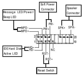
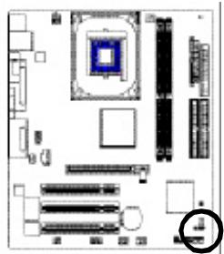
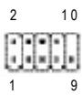
18) CI (CASE OPEN)
This 2 pin connector allows your system to enable or disable the "case open" item in BIOS if the system case begin remove.

| PinNo. | Definition |
| 1 | Signal |
| 2 | GND |
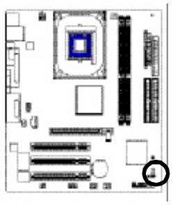
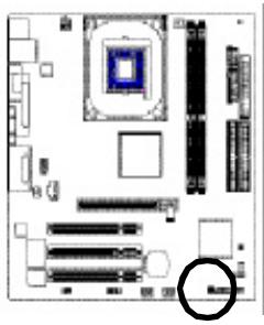
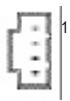
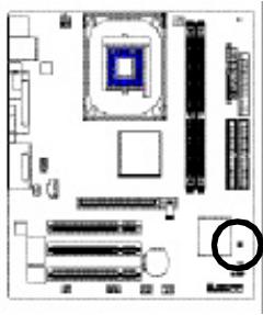
19) CLR_CMOS (Clear CMOS)
You may clear the CMOS data to its default values by this jumper. To clear CMOS, temporarily shor 1-2 pin. Default doesn't include the "Shunter" to prevent from improper use this jumper.
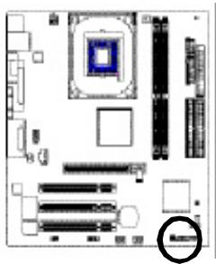
1 Open: Normal
1 Close: Clear CMOS
Chapter 2 BIOS Setup
BIOS Setup is an overview of the BIOS Setup Program. The program that allows users to modify the basic system configuration. This type of information is stored in battery-backed CMOS RAM so that it retains the Setup information when the power is turned off.
ENTERING SETUP
Powering ON the computer and pressing immediately will allow you to enter Setup. If you require more advanced BIOS settings, please go to "Advanced BIOS" setting menu. To enter Advanced BIOS setting menu, press "Ctrl+F1" key on the BIOS screen.
CONTROL KEYS
| <↑><↓><←><→ | Move to select item |
| <Enter> | Select Item |
| <Esc> | Main Menu - Quit and not save changes into CMOS Status Page Setup Menu and Option Page Setup Menu - Exit current page and return to Main Menu |
| <+/PgUp> | Increase the numeric value or make changes |
| </PgDn> | Decrease the numeric value or make changes |
| <F1> | General help, only for Status Page Setup Menu and Option Page Setup Menu |
| <F2> | Item Help |
| <F5> | Restore the previous CMOS value from CMOS, only for Option Page Setup Menu |
| <F6> | Load the file-safe default CMOS value from BIOS default table |
| <F7> | Load the Optimized Defaults |
| <F8> | Q-Flash utility |
| <F9> | System Information |
| <F10> | Save all the CMOS changes, only for Main Menu |
MainMenu
The on-line description of the highlighted setup function is displayed at the bottom of the screen.
Status Page Setup Menu / Option Page Setup Menu
Press F1 to pop up a small help window that describes the appropriate keys to use and the possible selections for the highlighted item. To exit the Help Window press
The Main Menu (For example: BIOS Ver. : E4)
Once you enter Award BIOS CMOS Setup Utility, the Main Menu (as figure below) will appear on the screen. The Main Menu allows you to select from eight setup functions and two exit choices. Use arrow keys to select among the items and press
CMOS Setup Utility-Copyright (C) 1984-2004 Award Software
| Standard CMOS Features Advanced BIOS Features Integrated Peripherals Power Management Setup PnP/PCI Configurations PC Health Status Frequency/Voltage Control | Top Performance Load Fail-Safe Defaults Load Optimized Defaults Set Supervisor Password Set User Password Save & Exit Setup Exit Without Saving |
| ESC: Quit F8: Q-Flash | ↑↓→←: Select Item F10: Save & Exit Setup |
| Time, Date, Hard Disk Type.. | |
Standard CMOS Features
This setup page includes all the items in standard compatible BIOS.
Advanced BIOS Features
This setup page includes all the items of Award special enhanced features.
- Integrated Peripherals
This setup page includes all onboard peripherals.
- PowerManagementSetup
This setup page includes all the items of Green function features.
PnP/PCI Configuration
This setup page includes all the configurations of PCI & PnP ISA resources.
PC Health Status
This setup page is the System auto detect Temperature, voltage, fan, speed.
Frequency/VoltageControl
This setup page is control CPU clock and frequency ratio.
- TopPerformance
If you wish to maximize the performance of your system, set "Top Performance" as "Enabled".
- Load Fail-Safe Defaults
Fail-Safe Defaults indicates the value of the system parameters which the system would be in safe configuration.
- Load Optimized Defaults
Optimized Defaults indicates the value of the system parameters which the system would be in best performance configuration.
- Set Supervisor Password
Change, set, or disable password. It allows you to limit access to the system and Setup, or just to Setup.
- SetUserPassword
Change, set, or disable password. It allows you to limit access to the system.
- Save & Exit Setup
Save CMOS value settings to CMOS and exit setup.
- Exit Without Saving
Abandon all CMOS value changes and exit setup.
Standard CMOS Features
CMOS Setup Utility-Copyright (C) 1984-2004 Award Software Standard CMOS Features
| Date (mm:dd:yy) | Fri, Jan 9 2004 | Item Help |
| Time (hh:mm:ss) | 22:31:24 | Menu Level▲ Change the day, month, year |
| IDE Primary Master | [None] | |
| IDE Primary Slave | [None] | |
| IDE Secondary Master | [None] | |
| IDE Secondary Slave | [None] | |
| Drive A | [1.44M, 3.5"] | <Month> |
| Drive B | [None] | Jan. to Dec. |
| Floppy 3 Mode Suport | [Disabled] | |
| Holt On | [A11, But Keyboard] | <Day> |
| Base Memory | 640K | 1 to 31 (or maximum allowed in the month) |
| Extended Memory | 127M | |
| Total Memory | 128M | 1999 to 2098 |
| ↑↓→←: Move Enter: Select +/-/PU/PD: Value F10: Save ESC: Exit F1: General Help F5: Previous Values F6: Fail-Save Default F7: Optimized Defaults | ||
Date
The date format is
Week The week, from Sun to Sat, determined by the BIOS and is display only
Month The month, Jan. Through Dec.
Day The day, from 1 to 31 (or the maximum allowed in the month)
Year The year, from 1999 through 2098
Time
The times format in
IDE Primary Master, Slave / IDE Secondary Master, Slave
The category identifies the types of hard disk from drive C to F that has been installed in the computer. There are two types: auto type, and manual type. Manual type is user-definable; Auto type which will automatically detect HDD type.
Note that the specifications of your drive must match with the drive table. The hard disk will not work properly if you enter improper information for this category.
If you select User Type, related information will be asked to enter to the following items. Enter the information directly from the keyboard and press
Cylinder Number of cylinders
Head Number of heads
Precomp Write precomp
Landing Zone Landing zone
Sector Number of sectors
If a hard disk has not been installed, select NONE and press
Drive A / Drive B
The category identifies the types of floppy disk drive A or drive B that has been installed in the computer.
None No floppy drive installed
360K, 5.25" 5.25 inch PC-type standard drive; 360K byte capacity.
1.2M, 5.25" 5.25 inch AT-type high-density drive; 1.2M byte capacity (3.5 inch when 3 Mode is Enabled).
720K, 3.5" 3.5 inch double-sided drive; 720K byte capacity
1.44M, 3.5" 3.5 inch double-sided drive; 1.44M byte capacity.
2.88M,3.5^ 3.5 inch double-sided drive; 2.88M byte capacity.
Floppy 3 Mode Support (for Japan Area)
Disabled Normal Floppy Drive. (Default value)
Drive A Drive A is 3 mode Floppy Drive.
Drive B Drive B is 3 mode Floppy Drive.
Both Drive A & B are 3 mode Floppy Drives.
Halt on
The category determines whether the computer will stop if an error is detected during power up.
No Errors The system boot will not stop for any error that may be detected and you will be prompted.
All Errors Whenever the BIOS detects a non-fatal error the system will be stopped.
All, But Keyboard The system boot will not stop for a keyboard error; it will stop for all other errors. (Default value)
All, But Diskette The system boot will not stop for a disk error; it will stop for all other errors.
All, But Disk/Key The system boot will not stop for a keyboard or disk error; it will stop for all other errors.
Memory
The category is display-only which is determined by POST (Power On Self Test) of the BIOS.
BaseMemory
The POST of the BIOS will determine the amount of base (or conventional) memory installed in the system.
The value of the base memory is typically 512K for systems with 512K memory installed on the motherboard, or 640K for systems with 640K or more memory installed on the motherboard.
Extended Memory
The BIOS determines how much extended memory is present during the POST.
This is the amount of memory located above 1 MB in the CPU's memory address map.
Advanced BIOS Features
CMOS Setup Utility-Copyright (C) 1984-2004 Award Software
Advanced BIOS Features
| First Boot Device | [Floppy] | Item Help | |
| Second Boot Device | [HDD-0] | Menu Level▶Select Boot Devicepriority | |
| Third Boot Device | [CDROM] | ||
| Boot Up Floppy Seek | [Disabled] | ||
| Password Check | [Setup] | [Floppy]Boot from floppy[LS120]Boot from LS120[HDD-0]Boot from First HDD[HDD-1]Boot from Second HDD | |
| ↑↓→←: Move Enter: Select F5: Previous Values | +/−/PU/PD: Value F10: Save F6: Fail-Save Default | ESC: Exit F1: General HelpF7: Optimized Defaults |
First/Second/ThirdBootDevice
Floppy Select your boot device priority by Floppy.
LS120 Select your boot device priority by LS120.
HDD-0~3 Select your boot device priority by HDD-0~3.
SCSI Select your boot device priority by SCSI.
CDROM Select your boot device priority by CDROM.
ZIP Select your boot device priority by ZIP.
USB-FDD Select your boot device priority by USB-FDD.
USB-ZIP Select your boot device priority by USB-ZIP.
USB-CDROM Select your boot device priority by USB-CDROM.
USB-HDD Select your boot device priority by USB-HDD.
LAN Select your boot device priority by LAN.
Disabled Select your boot device priority by Disabled.
Boot Up Floppy Seek
During POST, BIOS will determine the floppy disk drive installed is 40 or 80 tracks. 360K type is 40 tracks 720K, 1.2M and 1.44M are all 80 tracks.
▶ Enabled BIOS searches for floppy disk drive to determine it is 40 or 80 tracks. Note that BIOS can not tell from 720K, 1.2M or 1.44M drive type as they are all 80tracks.
Disabled BIOS will not search for the type of floppy disk drive by track number. Note that there will not be any warning message if the drive installed is 360K. (Default value)
PasswordCheck
System The system will not boot and will not access to Setup page if the correct password is not entered at the prompt.
Setup The system will boot but will not access to Setup page if the correct password is not entered at the prompt. (Default value)
Integrated Peripherals
CMOS Setup Utility-Copyright (C) 1984-2004 Award Software
Integrated Peripherals
| IDE1 Conductor Cable | [Auto] | Item Help |
| IDE2 Conductor Cable | [Auto] | Menu Level ▲ [Auto] Auto-detect IDE cable type |
| On-Chip Primary PCI IDE | [Enabled] | |
| On-Chip Secondary PCI IDE | [Enabled] | |
| AC97 Audio | [Enabled] | |
| Onboard LAN Device (*) | [Enabled] | [ATA66/100/133] Set Conductor cable to ATA66/100/133 (80-pins) |
| System Share Memory Size | [32MB] | |
| USB Controller | [Enabled] | |
| USB Legacy Support | [Disabled] | |
| Init Display First | [AGP] | |
| Onboard Serial Port A | [3F8/IRQ4] | [ATA33] Set Conductor cable to ATA33 (40-pins) |
| Onboard Serial Port B | [2F8/IRQ3] | |
| Serial Port B Mode | [Normal] | |
| Onboard Parallel Port | [378/IRQ7] | |
| Parallel Port Mode | [ECP] | |
| x EPP Mode Select | EPP1.7 | |
| ECP Mode Use DMA | [3] | |
| Game Port Address | [201] | |
| Midi Port Address | [330] | |
| Midi Port IRQ | [10] | |
| ↑↓→←: Move Enter: Select +/-/PU/PD: Value F10: Save ESC: Exit F1: General Help F5: Previous Values F6: Fail-Save Default F7: Optimized Defaults | ||
Auto Will be automatically detected by BIOS.(Default Value)
AT66/100/133 Set IDE1 Conductor Cable to ATA66/100/133 (Please make sure your IDE device and cable is compatible with ATA66/100/133).
ATA33 Set IDE1 Conductor Cable to ATA33 (Please make sure your IDE device and cable is compatible with ATA33).
IDE2 Conductor Cable
Auto Will be automatically detected by BIOS. (Default Value)
ATA66/100/133 Set IDE2 Conductor Cable to ATA66/100/133 (Please make sure your IDE device and cable is compatible with ATA66/100/133).
ATA33 Set IDE2 Conductor Cable to ATA33 (Please make sure your IDE device and cable is compatible with ATA33).
On-Chip Primary PCI IDE
Enabled Enable onboard 1st channel IDE port (Default value)
Disabled Disable onboard 1st channel IDE port.
On-Chip Secondary PCI DE
Enabled Enable onboard 2nd channel IDE port (Default value)
Disabled Disable onboard 2nd channel IDE port.
AC97 Audio
Enabled Enable onboard AC'97 audio function. (Default value)
Disabled Disable this function.
"For 8S651M-RZ only.
Onboard LAN Device
Enabled Enable onboard LAN device. (Default value)
Disabled Disable onboard LAN device.
System Share Memory Size
4MB/8MB/16MB/32MB/64MB Set onchip VGA shared memory size.(Default Value:32MB)
USB Controller
Enabled Enable USB Controller. (Default value)
Disabled Disable USB Controller.
USB Legacy Support
Enabled Enable USB Legacy Support.
Disabled Disable USB Legacy Support. (Default value)
Init Display First
AGP Set Init Display First to AGP. (Default value)
PCI Set Init Display First to PCI.
Onboard Serial Port A
Auto BIOS will automatically setup the port A address.
3F8/IRQ4 Enable onboard Serial port A and address is 3F8. (Default value)
2F8/IRQ3 Enable onboard Serial port A and address is 2F8.
3E8/IRQ4 Enable onboard Serial port A and address is 3E8.
2E8/IRQ3 Enable onboard Serial port A and address is 2E8.
Disabled Disable onboard Serial port A.
Onboard Serial Port B
Auto BIOS will automatically setup the port B address.
3F8/IRQ4 Enable onboard Serial port B and address is 3F8.
2F8/IRQ3 Enable onboard Serial port B and address is 2F8. (Default value)
3E8/IRQ4 Enable onboard Serial port B and address is 3E8.
2E8/IRQ3 Enable onboard Serial port B and address is 2E8.
Disabled Disable onboard Serial port B.
Serial Port B Mode
(This item allows you to determine which Infra Red(IR) function of Onboard I/O chip)
ASKIR Set onboard I/O chip UART to ASKIR Mode.
IrDA Set onboard I/O chip UART to IrDA Mode.
Normal Set onboard I/O chip UART to Normal Mode. (Default Value)
Onboard Parallel port
378/IRQ7 Enable onboard LPT port and address is 378/IRQ7. (Default Value)
278 / IRQ5 Enable onboard LPT port and address is 278/IRQ5.
Disabled Disable onboard LPT port.
3BC/IRQ7 Enable onboard LPT port and address is 3BC/IRQ7.
""For 8S651M-RZ only.
Parallel Port Mode
SPP Using Parallel port as Standard Parallel Port.
EPP Using Parallel port as Enhanced Parallel Port.
ECP Using Parallel port as Extended Capabilities Port (Default Value)
ECP+EPP Using Parallel port as ECP & EPP mode.
EPP Mode Select
EPP 1.9 Compliant with EPP 1.9 version.
EPP 1.7 Compliant with EPP 1.7 version.(Default Value)
ECP Mode Use DMA
3 Set ECP Mode Use DMA to 3. (Default Value)
1 Set ECP Mode Use DMA to 1.
Game Port Address
201 Set Game PortAddress to 201. (Default Value)
209 Set Game Port Address to 209.
Disabled Disable this function.
Midi Port Address
290 Set Midi Port Address to 290.
300 Set Midi Port Address to 300.
330 Set Midi Port Address to 330.(Default Value)
Disabled Disable this function.
Midi Port IRQ
5 Set Midi Port IRQ to 5.
10 Set Midi Port IRQ to 10. (Default Value)
Power Management Setup
CMOS Setup Utility-Copyright (C) 1984-2004 Award Software Power Management Setup
| ACPI Suspend Type | [S1 (POS)] | Item Help | |||
| Soft-Off by PWR_BTTN | [Off] | Menu Level ▲ [S1] | |||
| System After AC Back | [Off] | Set suspend type to Power On Suspend under ACPI OS | |||
| IRQ [3-7, 9-15], NMI | [Enabled] | ||||
| ModemRingOn | [Enabled] | ||||
| PME Event Wake Up | [Enabled] | ||||
| Power On by Keyboard | [Disabled] | ||||
| Power On by Mouse | [Disabled] | ||||
| Resume by Alarm | [Disabled] | ||||
| x Month Alarm | NA | [S3] | |||
| x Day (of Month) | 0 | Set suspend type to Suspend to RAM under ACPI OS | |||
| x Time (hh:mm:ss) | 0 0 0 | ||||
| Power LED in S1 state | [Blinking] | ||||
| ↑↓→←: Move Enter: Select +/-/PU/PD: Value F10: Save ESC: Exit F1: General Help F5: Previous Values F6: Fail-Save Default F7: Optimized Defaults | |||||
ACPI Suspend Type
S1(POS) Set ACPI suspend type to S1. (Default Value)
S3(STR) SetACPI suspend type to S3.
Soft-off by PWR_BTTN
Off The user press the power button once, he can turn off the system. (Default Value)
Suspend The user press the power button once, then the system will can enter suspend mode.
System after AC Back
LastState When AC-power back to the system, the system will return to the Last state before AC-power off.
Off When AC-power back to the system, the system will be in "Off" state. (Default Value)
On When AC-power back to the system, the system will be in "On" state.
IRQ [3-7, 9-15], NMI
Disabled Disable this function.
Enabled Enable this function. (Default value)
ModemRingOn
Disabled Disable Modem Ring on function.
Enabled Enable Modem Ring on function. (Default Value)
PME Event Wake Up
Disabled Disable this function.
Enabled Enable PME Event Wake up. (Default Value)
Power On by Keyboard
Password Input password (from 1 to 8 characters) and press Enter to set the Keyboard Power On Password.
Any Key Set Keyboard power on by any key.
Disabled Disable this function. (Default Value)
Power On by Mouse
Enabled Enable Power On by Mouse function.
Disabled Disable this function. (Default Value)
Resume by Alarm
You can set "Resume by Alarm" item to enabled and key in Data/time to power on system.
Disabled Disable this function. (Default Value)
Enabled Enable alarm function to POWER ON system.
If RTC Alarm Lead To Power On is Enabled.
Month Alarm : NA, 1~12
Day (of Month): 0-31
Time (hh: mm: ss): (0 23):(0 59):(0 59)
Power LED in S1 state
Blinking In standby mode(S1), power LED will blink. (Default Value)
Dual/OFF In standby mode(S1):
a. If use single color LED, power LED will turn off.
b. If use dual color LED, power LED will turn to another color.
PnP/PCI Configurations
CMOS Setup Utility-Copyright (C) 1984-2004 Award Software PnP/PCI Configurations
| PCI 1 IRQ Assignment [Auto] PCI 2 IRQ Assignment [Auto] PCI 3 IRQ Assignment [Auto] | Item Help |
| Menu Level◆ Device(s) using this INT: Display Cntlcr -Bus 1 Dev 0 Func 0 | |
| ↑↓→←: Move Enter: Select +/-/PU/PD: Value F10: Save ESC: Exit F1: General Help F5: Previous Values F6: Fail-Save Default F7: Optimized Defaults | |
PCI 1 IRQ Assignment
Auto Auto assign IRQ to PCI 1. (Default value)
3,4,5,7,9,10,11,12,14,15 Set IRQ 3,4,5,7,9,10,11,12,14,15 to PCI 1.
PCI 2 IRQ Assignment
Auto Auto assign IRQ to PCI 2. (Default value)
3,4,5,7,9,10,11,12,14,15 Set IRQ 3,4,5,7,9,10,11,12,14,15 to PCI 2.
PCI 3 IRQ Assignment
Auto Auto assign IRQ to PCI 3. (Default value)
3,4,5,7,9,10,11,12,14,15 Set IRQ 3,4,5,7,9,10,11,12,14,15 to PCI 3.
PCI Health Status
CMOS Setup Utility-Copyright (C) 1984-2004 Award Software
PC Health Status
| Reset Case Open Status | [Disabled] | Item Help | |||
| Case Opened | No | Menu Level↑ | |||
| VCORE | 1.71V | ||||
| +3.3V | 3.29V | ||||
| +5V | 4.99V | ||||
| +12V | 11.73V | ||||
| Current System Temperature | 33°C/ 91°F | ||||
| Current CPU Temperature | 27°C/ 80°F | ||||
| Current CPU FAN Speed | 4821 RPM | ||||
| Current SYSTEM FAN Speed | 0 RPM | ||||
| CPU Warning Temperature | [Disabled] | ||||
| CPU FAN Fail Warning | [Disabled] | ||||
| SYSTEM FAN Fail Warning | [Disabled] | ||||
| ↑↓→←: Move Enter: Select +/-/PU/PD: Value F10: Save ESC: Exit Fl: General Help F5: Previous Values F6: Fail-Save Default F7: Optimized Defaults | |||||
Reset Case Open Status
Case Opened
If the case is closed, "Case Opened" will show "No".
If the case have been opened, "Case Opened" will show "Yes".
If you want to reset "Case Opened" value, set "Reset Case Open Status" to
"Enabled" and save CMOS, your computer will restart.
Current Voltage (V) VCORE / +3.3V / +5V / +12V
Detect system's voltage status automatically.
Current System/CPU Temperature
Detect System/CPU Temp. automatically.
Current CPU/SYSTEM FAN Speed (RPM)
Detect CPU/SYSTEM Fan speed status automatically.
CPU Warning Temperature
60^ / 140^ Monitor CPU Temp. at 60^ / 140^
70^ / 158^ Monitor CPU Temp. at 70^ / 158^
80^ / 176^ Monitor CPU Temp. at 80^ / 176^
90^ / 194^ Monitor CPU Temp. at 90^ / 194^
Disabled Disable this function.(Default value)
CPU FAN Fail Warning
Disabled Fan Warning Function Disable. (Default value)
Enabled Fan Warning Function Enable.
SYSTEM FAN Fail Warning
Disabled
Fan Warning Function Disable. (Default value)
Enabled
Fan Warning Function Enable.
Frequency/Voltage Control
CMOS Setup Utility-Copyright (C) 1984-2004 Award Software
Frequency/Voltage Control
| CPU Clock Ratio | [10X] | Item Help | |
| Linear Frequency Control | [Disabled] | ||
| x CPU Clock (MHz) | 100 | Menu Level ▲ | |
| x DRAM Clock (MHz) | AUTO | ||
| x AGP Clock (MHz) | AUTO | ||
| x PCI Clock (MHz) | AUTO | ||
| ↑↓→←: Move Enter: Select +/-/PU/PD: Value F10: Save ESC: Exit F1: General HelpF5: Previous Values F6: Fail-Save Default F7: Optimized Defaults | |||
CPU Clock Ratio
This setup option will automatically assign by CPU detection.
For Willamette CPU:
8X~23X default: 14X
For C-Stepping P4:
8X,10X~24X default 15X
For Northwood CPU:
12X~24X default: 16X
The option will display "Locked" and read only if the CPU ratio is not changeable.
Linear Frequency Control
Disabled
Disable this function. (Default value)
Enabled
Enable this function.
CPU Clock
100-355
Select CPU Clock to 100MHz~355MHz.
If you use FSB400 Pentium 4 processor, please set "CPU Clock" to 100MHz. If you use FSB533
Pentium 4 processor, please set "CPU Clock" to 133MHz . If you use FSB800 Pentium 4
processor, please set "CPU Clock" to 200MHz.
Incorrect using it may cause your system broken. For power End-User use only!
DRAM Clock (MHz)
Please set DRAM Clock according to your requirement.
If you use DDR200 DRAM module, please set "DRAM Clock(MHz)" to 200. If you use DDR333
DRAM module, please set "DRAM Clock(MHz)" to 333.
Incorrect using it may cause your system broken. For power End-User use only!
AGP Clock (MHz)
Please set AGP Clock according to your requirement. Incorrect using it may cause your system broken. For power End-User use only!
PCI Clock (MHz)
Please set PCI Clock according to your requirement. Incorrect using it may cause your system broken. For power End-User use only!
Top Performance
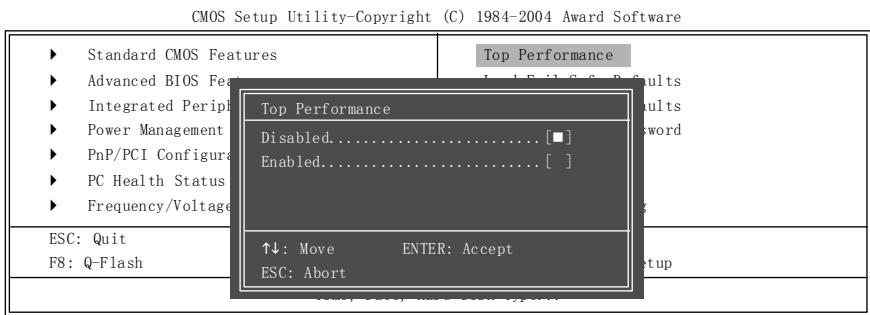
If you wish to maximize the performance of your system, set "Top Performance" as "Enabled".
Disabled Disable this function. (Default Value)
Enabled Enable Top Performance function.
"Top Performance" will increase H/W working speed. Different system configuration (both H/W component and OS) will effect the result. For example, the same H/W configuration might not run properly with Windows XP, but works smoothly with Windows NT. Therefore, if your system is not perform enough, the reliability or stability problem will appear sometimes, and we will recommend you disabling the option to avoid the problem as mentioned above.
Load Fail-Safe Defaults
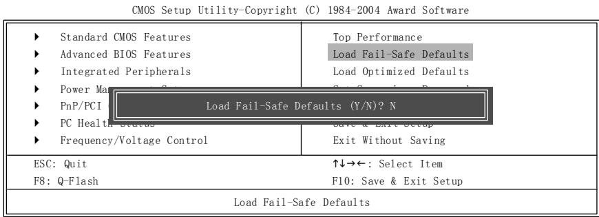
Fail-Safe defaults contain the most appropriate values of the system parameters that allow minimum system performance.
Load Optimized Defaults
CMOS Setup Utility-Copyright (C) 1984-2004 Award Software
| Standard CMOS Features Advanced BIOS Features Integrated Peripherals Power Management PnP/PCI Load Optimized Defaults (Y/N)? N PC Health Status Frequency/Voltage Control | Top Performance Load Fail-Safe Defaults Load Optimized Defaults |
| Exit Without Saving | |
| ESC: Quit F8: Q-Flash | ↑↓→←: Select Item F10: Save & Exit Setup |
| Load Optimized Defaults | |
Selecting this field loads the factory defaults for BIOS and Chipset Features which the system automatically detects.
Set Supervisor/User Password
CMOS Setup Utility-Copyright (C) 1984-2004 Award Software
| Standard CMOS Features | Top Performance |
| Advanced BIOS Features | Load Fail-Safe Defaults |
| Integrated Peripherals | Load Optimized Defaults |
| Power Management | Get Programming Requirements |
| PnP/PCI Enter Password: | |
| PC Health Status | Save & Exit Setup |
| Frequency/Voltage Control | Exit Without Saving |
| ESC: Quit | ↑↓→←: Select Item |
| F8: Q-Flash | F10: Save & Exit Setup |
| Change/Set/Disable Password | |
When you select this function, the following message will appear at the center of the screen to assist you in creating a password.
Type the password, up to eight characters, and press
To disable password, just press
The BIOS Setup program allows you to specify two separate passwords:
SUPERVISOR PASSWORD and a USER PASSWORD. When disabled, anyone may access all BIOS Setup program function. When enabled, the Supervisor password is required for entering the BIOS Setup program and having full configuration fields, the User password is required to access only basic items.
If you select "System" at "Password Check" in Advance BIOS Features Menu, you will be prompted for the password every time the system is rebooted or any time you try to enter Setup Menu.
If you select "Setup" at "Password Check" in Advance BIOS Features Menu, you will be prompted only when you try to enter Setup.
Save & Exit Setup
CMOS Setup Utility-Copyright (C) 1984-2004 Award Software
| Standard CMOS Features Advanced BIOS Features Integrated Peripherals Power Management PnP/PCI Save to CMOS and EXIT (Y/N)? Y PC Health Status Frequency/Voltage Control | Top Performance Load Fail-Safe Defaults Load Optimized Defaults |
| Exit Without Saving | |
| ESC: Quit F8: Q-Flash | ↑↓→←: Select Item F10: Save & Exit Setup |
| Save Data to CMOS | |
Type "Y" will quit the Setup Utility and save the user setup value to RTC CMOS.
Type "N" will return to Setup Utility.
Exit Without Saving
CMOS Setup Utility-Copyright (C) 1984-2004 Award Software
| Standard CMOS Features Advanced BIOS Features Integrated Peripherals Power Management Status PnP/PCI Quit Without Saving (Y/N)? N PC Health Status Save & Exit Setup Frequency/Voltage Control Exit Without Saving | |
| ESC: Quit ↑↓→←: Select Item F8: Q-Flash F10: Save & Exit Setup | |
| Abandon all Data |
Type "Y" will quit the Setup Utility without saving to RTC CMOS.
Type "N" will return to Setup Utility.
Chapter 3 Install Drivers
Install Drivers

Pictures below are shown in Windows XP
Insert the driver CD-title that came with your motherboard into your CD-ROM drive, the driver CD-title will auto start and show the installation guide. If not, please double click the CD-ROM device icon in "My computer", and execute the setup.exe.
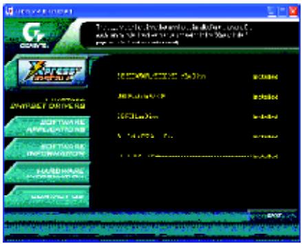
INSTALL CHIPSET DRIVER
This page shows the drivers that need to be installed for the system. Click each item to install the driver manually or switch to the to install the drivers automatically.
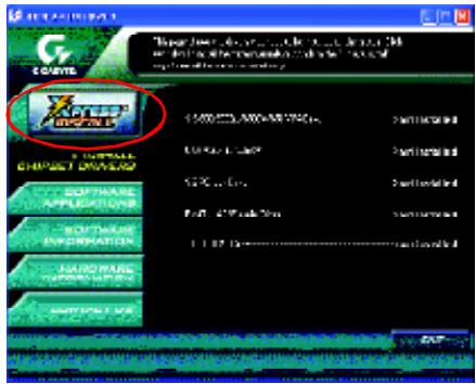
Massage: Some device drivers will restart your system automatically. After restarting your system the "Xpress Install" will continue to install other drivers.
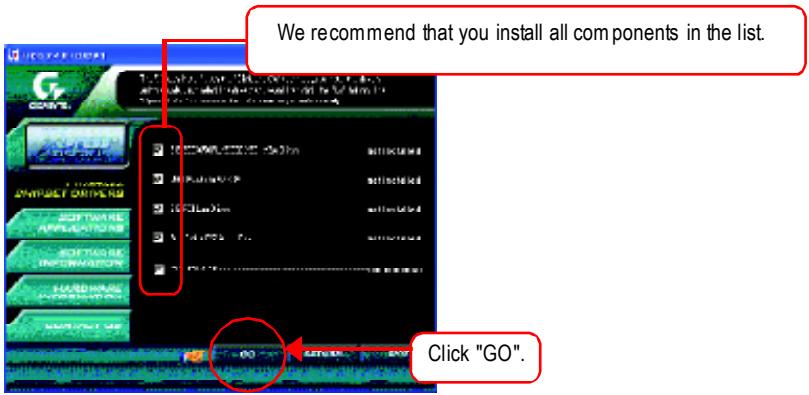
The "Xpress Install" uses the "Click and Go" technology to install the drivers automatically. Just select the drivers you want then click the "GO" button. The will execute the installation for you by itself.
Driver install finished!! you have to reboot system!!
Item Description
SiS 650/650GL/650GX/651 VGA Driver
VGA driver for VGA integrated SiS 650/650GL/650GX/651chipset.
USB Patch for WinXP
This patch driver can help you to resolve the USB device wake up S3 hang up issue in XP.
SiSPCI Lan Driver (^)
SiS 962L/963L LAN driver.
RealTek AC97 Audio Driver
Install RealTek AC97 audio driver.
SIS USB 2.0 Driver
It is recommended that you use the Microsoft Windows update for the most updated driver for XP/2K.

If your CD doesn't have SiS® USB2.0 driver, please download the USB2.0 driver from Microsoft® website (www.microsoft.com) for USB2.0 devices support.
Please also note that Microsoft® USB2.0 driver is currently supported by Windows XP and Windows 2000 only.
Once we get the latest SiS® USB2.0 driver for Windows 98 and Windows ME, we will put the driver on GIGABYTE website asap. (http://www.gigabyte.com.tw).

For USB2.0 driver support under Windows XP operating system, please use Windows Service Pack. After install Windows Service Pack, it will show a question mark "?" in "Universal Serial Bus controller" under "Device Manager". Please remove the question mark and restart the system (System will auto-detect the right USB2.0 driver).
"For 8S651M-RZ only.
CONTACT US
Contactus via the information in this page all over the world.
Taiwan
Gigabyte TechnologyCo., Ltd.
Address: No.6, Bau Chiang Road, Hsin-Tien, Taipei Hsien,
Taiwan,R.O.C.
Tel:886(2)8912-4888
Fax:886(2)8912-4004
Tech.Support:
http://tw.giga-byte.com/TechSupport/ServiceCenter.htm
Non-Tech.Support (Sales/Marketing issues):
Address: 17358 Railroad St, City of Industry, CA91748.
Tel:1(626)854-9338
Fax:1(626)854-9339
Tech.Support:
http://www.giga-byte.com/TechSupport/ServiceCenter.htm
Non-Tech.Support(Sales/Marketing issues):
Non-Tech.Support(Sales/Marketing issues):
Non-Tech.Support (Sales/Marketing issues):
Address: Verdunplein 85627 SZ, Eindhoven, The Netherlands
Tel:+31402902088
NL Tech.Support:0900-GIGABYTE(0900-44422983, 0.2/M)
BEtech.Support:0900-84034(0.4/M)
Fax: +31 40 290 2089
Tech.Support:
http://nz.giga-byte.com/TechSupport/ServiceCenter.htm
Non-Tech.Support (Sales/Marketing issues):
Non-Tech.Support(Sales/Marketing issues):