GIGABYTE GA-H55M-S2 - Motherboard

GA-H55M-S2 - Motherboard GIGABYTE - Free user manual and instructions

Find the device manual for free GA-H55M-S2 GIGABYTE in PDF.

📄 80 pages English EN Download 💬 AI Question 11 questions ⚙️ Specs
Notice GIGABYTE GA-H55M-S2 - page 9
View the manual : Français FR English EN
Pick your language and provide your email: we'll send you a specifically translated version.
Product type ATX Motherboard
Brand GIGABYTE
Model GA-H55M-S2
CPU Socket LGA1156 (Intel Core i7/i5/i3/Pentium)
Chipset Intel H55 Express
Memory Type DDR3 (2 slots, dual channel, max 16 GB)
Integrated Graphics Intel HD Graphics via D-Sub (requires CPU with IGP)
Audio Realtek ALC888, HD Audio 2/4/5.1/7.1 channels
Network Realtek RTL8111E Gigabit Ethernet
Expansion Slots 1 PCI Express x16, 1 PCI Express x1, 2 PCI
Storage 6 SATA 3 Gb/s ports (Intel H55)
USB Ports 12 USB 2.0 ports (8 rear, 4 via headers)
Rear Panel Connectors 1 PS/2 keyboard, 1 PS/2 mouse, 1 D-Sub, 1 RJ-45, 3 audio jacks
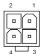
Required Power Supply ATX 24-pin + ATX 12V 4-pin
BIOS AWARD BIOS, 2 x 8 Mbit Flash
Included Software Norton Internet Security (OEM)
Supported Operating Systems Windows 7/Vista/XP
Maintenance Avoid static electricity, maintain adequate ventilation
Safety Unplug the power supply before handling
Spare Parts / Repairability CR2032 CMOS battery, optional USB/audio brackets

Frequently Asked Questions - GA-H55M-S2 GIGABYTE

How to install RAM memory?
Turn off the computer and unplug the power cord. Open the clips of the DDR3 DIMM slots. Align the notch of the module with the key of the slot and insert it vertically until the clips snap into place. For dual channel, install two identical modules in slots DDR3_1 and DDR3_2.
How to clear CMOS values?
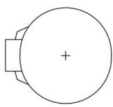
Turn off the computer and unplug the power. Use the CLR_CMOS jumper: place a jumper on the two pins for a few seconds (or use a screwdriver to short them). Return the jumper to its default position (on a single pin). You can also remove the CR2032 battery for one minute.
What do the beeps emitted at startup mean?
The Award BIOS beep codes are: 1 short beep = successful startup; 1 long, 2 short = monitor or graphics card error; 1 long, 3 short = keyboard error; continuous long beeps = graphics card not inserted properly; continuous short beeps = power supply error.
How to enable dual channel mode for memory?
Dual channel mode is automatically enabled when two identical modules are installed in slots DDR3_1 and DDR3_2. Use modules of the same capacity, brand, and speed for optimal performance.
How to update the BIOS?
Two utilities are available: Q-Flash (accessible at startup by pressing F8) allows updating from a USB key without an operating system. @BIOS is a Windows utility that downloads and installs the latest version from the Internet.
Why is the screen black after power on?
First check that the graphics card is properly inserted (or use the D-Sub port if the CPU has integrated GPU). Make sure the monitor is on and connected. Also check that the power supply is properly connected (ATX_12V and ATX connectors). If the problem persists, try to reset the CMOS.
How to connect the front panel cables?
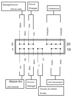
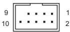
Locate the F_PANEL connector on the motherboard. Connect the cables according to the pinout: Power SW (switch), Reset SW, Power LED (pay attention to polarity), HDD LED and Speaker. Consult the manual for the exact pinout.
How to install the CPU cooler?
Apply a thin layer of thermal paste on the CPU. Place the cooler aligning the four pegs with the holes on the motherboard. Press diagonally on each peg until you hear a click. Connect the fan power cable to the CPU_FAN connector.
How to configure 5.1 channel sound?
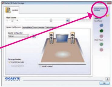
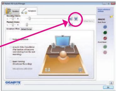
Install the Realtek audio driver. Open the HD Audio Manager. Connect speakers to the corresponding jacks (front: green, rear: black, center/sub: orange). In the 'Speaker Configuration' tab, select 5.1 channels. Use a front audio module to enable additional channels.
What to do if the computer does not start?
Follow the troubleshooting procedure: 1) Disconnect all peripherals and cables. 2) Check that the motherboard is not short-circuited with the chassis. 3) Ensure the cooler is properly attached and the fan spins. 4) Check that memory is properly installed. 5) Reinsert the graphics card. 6) If nothing works, clear the CMOS and try again.

User questions about GA-H55M-S2 GIGABYTE

1 question about this device. Answer the ones you know or ask your own.

Ask a new question about this device

The email remains private: it is only used to notify you if someone responds to your question.

How to connect the ON/OFF buttons, hard drive indicator, CD opening, and speaker to the GIGABYTE GA-H55M-S2 motherboard?
Frequently Asked Questions - 29/11/2025
Response Notice-Facile

The GIGABYTE GA-H55M-S2 motherboard has a F_PANEL connector located in the lower right part of the motherboard. This connector accommodates the case cables for the power button, indicator lights, and speaker. Here’s how to correctly connect each component.

Connector location: The F_PANEL is a pin block grouping the front panel connections. Refer to your motherboard manual to precisely identify its position, usually at the bottom right, near other front panel connectors like the audio connector.

Main connections: The ON/OFF (PWR) button uses a red cable and connects to the pins dedicated to the power switch. This connector has no defined polarity, so you can insert it in either direction. The hard drive indicator (HD) is a blue cable that lights up during read/write operations of the disk. Unlike the power button, this LED indicator has polarity: respect the + and - markings on the motherboard and on the cable connector. The speaker (SPEAK) is an orange connector that emits diagnostic beeps at system startup. The reset button (RES) is a green cable that allows you to restart the computer in case of a freeze. Optionally, the CI (intrusion) connector in gray can receive a case open sensor.

Cable connections: Before connecting, identify the color code of the cables provided with your case and match it to the pins of the F_PANEL according to the installation manual instructions. For the LEDs (hard drive indicator and other lights), ensure that the pin marked + (positive) of the cable corresponds to the + pin of the connector on the motherboard, and the same for the - (negative) pin. Incorrect polarity of the LEDs will not cause damage, but they simply will not light up. Finally, the power button and reset button have no specific polarity and can be connected in either direction.

Case of the CD/DVD drive opening: The eject button of the CD/DVD or Blu-ray drive is not connected to the GA-H55M-S2 motherboard. This button is directly connected to the optical drive by a proprietary cable. To ensure ejection works, simply make sure the drive is properly powered via a Molex or SATA power connector, and that it is connected to the motherboard via an IDE or SATA port depending on your setup.

Safety tips: Before plugging in the computer, double-check that all cables are securely inserted into the F_PANEL connector. Poor connections can prevent the system from starting. For polarity LED indicators, refer to your manual or standard color codes (red or white wire for positive, black for negative). If after connecting an element does not work, first check the polarity of the LED before suspecting a hardware fault.

Respond (be the first)

Download the instructions for your Motherboard in PDF format for free! Find your manual GA-H55M-S2 - GIGABYTE and take your electronic device back in hand. On this page are published all the documents necessary for the use of your device. GA-H55M-S2 by GIGABYTE.

USER MANUAL GA-H55M-S2 GIGABYTE

(£m)Date: 21 Jun 2010Name:Timy Huang
(Samp)
Manufacturer/ImproperSignatureTony Huang
☐ EN 60335Draft of Honduras and similar territories and similar requirements for Honduras and similar government☐ EN 30091-1General and salary requirements for unanchised power systems (JPS)
☐ EN 60065Sandy requirement for non-proved institutions and related apparatus for handling geothermal business equipment☐ EN 60500Sandy or related requirements for handling geothermal business equipment
☐ EN 60335Draft of Honduras and similar territories and similar requirements for Honduras and similar government☐ EN 30091-1General and salary requirements for unanchised power systems (JPS)
☐ EN 60065Sandy requirement for non-proved institutions and related apparatus for handling geothermal business equipment☐ EN 60500Sandy or related requirements for handling geifferential equipment
☐ EN 60335Draft of Honduras and similar territories and similar government☐ EN 30091-1General and salary requirements for unanchised power systems (JPS)
☐ EN VCE 6855Cardi adhesion physicians, Electrical equipment and technology equipment☐ EN 30091-2General and salary requirements for unanchised power systems (JPS)
☐ EN 65022Lands and methods of measurement of the cardi adhesion physicians or information technology equipment☐ EN 30091-2General and salary requirements for unanchised power systems (JPS)
☐ EN 65020Incentive from redo infrastructure of technological images and services☐ EN 30091-2ELEC requirements for unanchised power systems (JPS)
☐ EN 65015Lands and methods of measurement of the cardi adhesion physicians or technological images and services☐ EN 35014-2Incentive requirements for unanchised applications based on service requirements
☐ EN 65015Lands and methods of measurement of the cardi adhesion physicians or technological images and services☐ EN 35082-2Incentive requirements for unanchised applications based on service requirements
☐ EN 65014-1Lands and methods of measurement of the cardi adhesion physicians or technological images and services☐ EN 35082-1General and salary standards for 1
☐ EN 65013Lands and methods of measurement of the cardi adhesion physicians or technological images and services☐ EN 35024General and salary standards for 1
☐ EN 65011Lands and methods of measurement of the cardi adhesion physicians or technological images and services☐ EN 61000-3-2Incentive requirements for unanchised applications based on service requirements

Date: 21 juin 2010

Signature: Eric Lu Representative Person's Name: ERIC LU

This device complies with part 15 of the FCC Rules. Operation is subject to the following two conditions: (1) This device may not cause harmful and (2) this device must accept any inference received, including that may cause undesired operation.

FCC Part 15, Subpart B, Section 15.107(a) and Section 15.109 (a), Class B Digital Device Supplementary Information:

Product Name: Carne mare Model Number: GA4H55M-S2 Confirms to the following specifications:

City of Industry, CA 91748 Phone/Fax No: (818) 854-9338/ (818) 854-9339 Herby declares that the product

Address: 17358 Railroad Street Responsible Party Name: G.B.T. INC. (U.S.A.)

GIGABYTE GA-H55M-S2 - 1

Per FCC Part 2 Section 2.1077(a)

DECILARIATION OF COMPANY

Droits d'auteur

natural_image Close-up of a blue computer motherboard with a highlighted CPU socket and a magnified view showing the next component (no text or symbols visible)

Table des matières

Configuration mémoire double canal ....15 1-4-2 Installation

3-7 Nouveaux services publics 56

natural_image Close-up of a computer motherboard with visible slots, chips, and connectors (no readable text or symbols)

8 ports USB 2.0/1.1, 1 port

Format MicroATX ; 24,4 cm x 21,0 cm

natural_image Diagram of a computer motherboard with CPU socket and RAM slots, no text or symbols present

Clé d'alignement
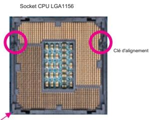
Socket CPU LGA1156 Clé d'alignement

natural_image Close-up of a mechanical assembly with a magnified inset showing a finger pressing a component (no visible text or symbols)
natural_image Close-up of a microprocessor chip with four red-circled mounting holes (no text or symbols visible)

Étape 3 :

natural_image Close-up of a blue CPU socket on a circuit board (no visible text or symbols)

Étape 5 :

natural_image Close-up of hands installing a black CPU socket on a blue circuit board (no text or symbols visible)

Étape

natural_image Close-up of hands installing a CPU socket on a motherboard with a magnified inset showing the chip (no text or symbols visible)

Étape 4 :

natural_image Close-up of a hand using a tool to adjust or install an electronic component on a CPU socket (no visible text or symbols)

NOTE:

natural_image Close-up of a blue computer motherboard with a central processor socket and surrounding circuitry (no visible text or symbols)

Étape 1 :

natural_image Close-up of a computer motherboard with a heatsink and cooling fan (no visible text or symbols)

Étape

natural_image Close-up of a blue circuit board with a central black and white component (no visible text or symbols)

Étape

natural_image Close-up of a computer motherboard with a highlighted mechanical component (no visible text or symbols)

Étape 4 :

natural_image Close-up of a computer motherboard with visible CPU socket and connectors (no readable text or symbols)

Étape 6 :

natural_image Close-up of hands holding a CPU socket next to a motherboard, with no visible text or symbols on the socket or background.

Étape 1 :

natural_image Close-up of a computer motherboard with a CPU fan and RAM slots, no visible text or symbols

Étape 2 :

natural_image Diagram of a computer motherboard with labeled components and an arrow indicating direction (no text or symbols present)

Emplacement PCI Express x16

GIGABYTE GA-H55M-S2 - Table des matières - 2

Emplacement PCI
GIGABYTE GA-H55M-S2 - Table des matières - 3

Emplacement PCI Express x1
GIGABYTE GA-H55M-S2 - Table des matières - 4

natural_image Close-up of hands holding a computer motherboard with a cooling fan and CPU socket (no visible text or symbols)
natural_image Close-up of a finger pressing a blue plastic component on a circuit board (no visible text or symbols)
natural_image Diagram of a computer motherboard showing CPU socket, RAM slots, and memory card layout (no text or labels)
GIGABYTE GA-H55M-S2 - Table des matières - 5
ATX_12V

ATX_12V:

natural_image Top-down schematic of a computer motherboard showing CPU socket, RAM slots, and drive bays (no text or labels)

GIGABYTE GA-H55M-S2 - Table des matières - 6

GIGABYTE GA-H55M-S2 - Table des matières - 7

VENTILATEUR_DU_CPU :

natural_image Top-down view of a computer motherboard showing CPU socket, RAM slots, and drive bays (no text or labels)

SATA2_2 SATA2_1 SATA2_0
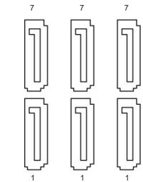
7 7 7 1 1 1

SATA2_5 SATA2_4
SATA2_3

natural_image Blue plastic cable with a connector, isolated on white background (no text or symbols)
natural_image Exploded view diagram of a computer motherboard showing CPU socket, RAM slots, and drive unit (no text or labels)
GIGABYTE GA-H55M-S2 - Table des matières - 9

natural_image Simple line drawing of a circular object with a plus sign at center, no text or symbols present
natural_image Top-down schematic of a computer motherboard showing CPU socket, RAM slots, and drive bays (no text or labels)
GIGABYTE GA-H55M-S2 - Table des matières - 10

flowchart
graph TD
    A["Message/Pouvoir"] --> B["LED de veille"]
    C["Pouvoir Charger"] --> D["MG+"]
    C --> E["MG-"]
    F["Conférencier"] --> G["PARLR+"]
    F --> H["PARLR-"]
    I["disque dur"] --> J["LED d'activité"]
    K["Remotheter Changer"] --> L["HD+"]
    M["PWR+"] --> N["Δ"]
    O["PWR-"] --> P["LED d'alimentation"]
    Q["Intrusion du châssis En-tête"] --> R["20"]
    S["19"] --> T["2"]
    U["2"] --> V["HD-"]
    W["20"] --> X["RES+"]
    Y["20"] --> Z["C+"]

- MSG/PWR (LED Message/Alimentation/Veille, jaune/violet) :

natural_image Top-down schematic of a computer motherboard showing CPU socket, RAM slots, and drive bays (no text or labels)

GIGABYTE GA-H55M-S2 - Table des matières - 11

natural_image Top-down schematic of a computer motherboard showing CPU socket, RAM slots, and memory drive (no text or labels)
GIGABYTE GA-H55M-S2 - Table des matières - 12

natural_image Top-down schematic of a computer motherboard showing CPU socket, RAM slots, and memory card (no text or labels)

GIGABYTE GA-H55M-S2 - Table des matières - 13

Ouvert : Normal

GIGABYTE GA-H55M-S2 - Table des matières - 14

2-2 Le menu principal

Mo Intelligent Tweaker (MIT)

Now Loading Please wait...

GIGABYTE Chipset Drivers Application Software Technical Manuals Contact System Download Center Auto Green Install Application Programs Click the "Install" button on the right of an application to install it Install GIGABYTE Utilities Install Application Software Install New Utilities G.O.M. (Gigabyte Online Manager) Size 9.11MB A web-based system management tool that allows client system hardware information such as CPU and memory and graphics card and much more to be monitored or controlled via a host. EasyScope 6 Size 22.30MB An easy-to-use Windows-based system enhancement utility allowing quick access to a anxiety of performance features. DMI Viewer Size 2.89MB DMI Viewer provides a management tool for viewing motherboard hardware information. Face Wizard Size 3.02MB Face Wizard provides utility for customizing BIOS boot up screen. getBIOS

3-3 Manuels techniques

3-7 Nouveaux services publics

4-1 Xpress Recovery2

Xpress RECOVERY 2

Étape 1 :

Étape 2 :

Étape 3 :

Étape 2 :

Étape 3 :
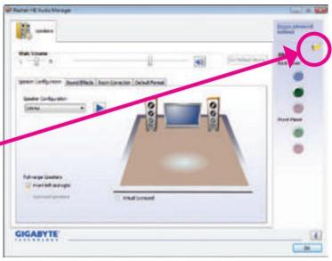
New Style Manager New Style New Style New Style New Style New Style New Style New Style New Style New Style New Style New Style New Style New Style New Style New Style New Style New Style New Style New Style New Style New Style New Style New Style New Style New Style New Style New Style New Style New Style New Style New Style New Style New Style New Style

New Style Manager New Style New Style Manager New Style Manager New Style Manager New Style Manager New Style Manager New Style Manager New Style Manager New Style Manager New Style Manager New Style Manager New Style Manager New Style Manager New Style Manager New Style Manager New Style Manager New Style Manager New Style Manager New Style Manager New Style Manager New Style Manager New Style Manager New Style Manager New Style Manager New Style Manager New Style Manager New Style Designer New Style Designer New Style Designer New Style Designer New Style Designer New Style Designer New Style Designer New Style Designer New Style Designer New Style Designer New Style Designer New Style Designer New Style Designer New Style Designer New Style Designer New Style Designer New Style Designer New Style Designer New Style Designer New Style Designer New Style Designer New Style Designer New Style Designer New Style Designer New Style Designer New Style Designer New Style Designer New Style Designer New Style Designer New Style Designer New Style Designer New Style Designer New Style Designer New Style Designer New Style Designer New Style Designer New Style Designer New Style Designer New Style Designer New Style Designer New Style Designer New Style Designer New Style Designer New Style Designer New Style Designer New Style Designers New Style Designers New Style Designers New Style Designers New Style Designers New Style Designers New Style Designers New Style Designers New Style Designers New Style Designers New Style Designers New Style Designers New Style Designers New Style Designers New Style Designers New Style Designers New Style Designers New Style Designers New Style Designers New Style Designers New Style Designes: New Style Designes: New Style Designes: New Style Designes: New Style Designes: New Style Designes: New Style Designes: New Style Designes: New Style Designes: New style design design design design design design design design design design design design design design design design design design design design design design design design design design design design design design design design design design design design design design design design design design design design design design design design design design design design design design design design design design design design design design design design design design design design design design design design design design design design design design design design design design design design design design design design design design design design design design design design design design design design document. Gigabyte

Étape 2 :

GIGABYTE GIGABYTE Mode: Linear Telephone Receiving Options Set Default Devices Product Volume Selected Device Selected Device Noise Suppression Automatic Edge Correction Use the function to ensure void decoding from the web recording. Base turning Directional recording Receiving Mode Control Add Advanced Settings Add Noise Add Color Add Sound Add Noise

Étape 4 :

Gigabyte Gigabyte Model: H-1 Audio Manager Receiving Values Receiving Image Preview Image Preview Image Audio Section Audio Section Audio Section Audio Section Audio Section Audio Section Audio Section Audio Section Audio Section Audio Section Audio Section Audio Section Audio Section Audio Section Audio Section Audio Section Audio Section Audio Section Audio Section Audio Section Audio Section Audio Section Audio Section Audio Section Audio Section Audio Section Audio Section Audio Section Audio Section Audio Section Audio Section Audio Section Audio Section Audio Section

Étape 5 :

Étape 3 :

Étape 4 :

Management Methods on Control of Pollution from Electronic Information Products (China RoHS Declaration)

Assistance technique et non technique (Ventes/Marketing) :

TECHNOLOGY FRANCE - France

Global Technical Service

Welcome to GIGABYTE Service system. If you want to submit new question or check our response, please enter your E- Mail address and press the button to log in. Your Email : 繁體中文 Deutsch 宋体中文 Français Polski English

Pour soumettre une question technique ou non technique (Ventes/

Manual assistant
Powered by Anthropic
Waiting for your message
Product information

Brand : GIGABYTE

Model : GA-H55M-S2

Category : Motherboard