
BVM-A14F5M - Monitor SONY - Free user manual and instructions
Find the device manual for free BVM-A14F5M SONY in PDF.


| Product Type | Professional CRT Broadcast Monitor |
| Brand | Sony |
| Model | BVM-A14F5M |
| Screen Size | 14 inches (diagonal) |
| Display Technology | Trinitron CRT |
| Resolution | Up to 1920 x 1080 (interlaced) |
| Input Formats | SDI, Composite, Y/C, Component, RGB, D-sub 15-pin |
| Dimensions (W x H x D) | Approx. 340 x 280 x 380 mm |
| Weight | Approx. 12 kg |
| Power Supply | AC 100-240 V, 50/60 Hz, 80 W |
| Main Functions | Color temperature adjustment, Blue only mode, Under scan, Aperture correction, Chroma phase control |
| Maintenance & Cleaning | Use a soft, dry cloth. Avoid solvents. Clean front panel and CRT gently. |
| Safety | Use a grounded outlet. Do not block ventilation. Avoid magnetic fields. |
| Spare Parts & Repairability | Authorized service only. Use genuine Sony parts. |
| General Information | Professional monitor for broadcast and post-production. |
Frequently Asked Questions - BVM-A14F5M SONY
User questions about BVM-A14F5M SONY
0 question about this device. Answer the ones you know or ask your own.
Ask a new question about this device
Download the instructions for your Monitor in PDF format for free! Find your manual BVM-A14F5M - SONY and take your electronic device back in hand. On this page are published all the documents necessary for the use of your device. BVM-A14F5M by SONY.
USER MANUAL BVM-A14F5M SONY
1st Edition (Revised 3)
Serial No. 2000001 and Higher
For Safety
Note
Insert the 4:3 mask (supplied).
To return to the 16:9 mask
H SIZE: Adjusts the width of the image.

V SIZE: Adjusts the height of the image.

AND MONITOR WILL RESTART
ARE YOU SURE?
AND MONITOR WILL RESTART
ARE YOU SURE?
To reduce the risk of fire or electric shock, do not expose this apparatus to rain or moisture.
To avoid electrical shock, do not open the cabinet. Refer servicing to qualified personnel only.
WARNING
THIS APPARATUS MUST BE EARTHED.
WARNING
- Use the approved Power Cord (3-core mains lead) / Appliance Connector / Plug with earthing-contacts that conforms to the safety regulations of each country if applicable.
- Use the Power Cord (3-core mains lead) / Appliance Connector / Plug conforming to the proper ratings (Voltage, Ampere).
If you have questions on the use of the above Power Cord / Appliance Connector / Plug, please consult a qualified service personnel.
For the customers in USA (BVM-A14F5U)
This equipment has been tested and found to comply with the limits for a Class A digital device, pursuant to Part 15 of the FCC Rules. These limits are designed to provide reasonable protection against harmful interference when the equipment is operated in a commercial environment. This equipment generates, uses, and can radiate radio frequency energy and, if not installed and used in accordance with the instruction manual, may cause harmful interference to radio communications. Operation of this equipment in a residential area is likely to cause harmful interference in which case the user will be required to correct the interference at his own expense.
You are cautioned that any changes or modifications not expressly approved in this manual could void your authority to operate this equipment.
All interface cables used to connect peripherals must be shielded in order to comply with the limits for a digital device pursuant to Subpart B of Part 15 of FCC Rules.
WARNING
Using this unit at a voltage other than 120 V may require the use of a different line cord or attachment plug, or both. To reduce the risk of fire or electric shock, refer servicing to qualified service personnel.
For the customers in Canada (BVM-A14F5U)
This Class A digital apparatus complies with Canadian ICES-003.
For the customers in Europe (BVM-A14F5M/BVM-A14F5A)
This product with the CE marking complies with both the EMC Directive (89/336/EEC) and the Low Voltage Directive (73/23/EEC) issued by the Commission of the European Community. Compliance with these directives implies conformity to the following European standards:
• EN60950-1: Product Safety
• EN55103-1: Electromagnetic Interference (Emission)
- EN55103-2: Electromagnetic Susceptibility (Immunity) This product is intended for use in the following Electromagnetic Environment: E4 (controlled EMC environment, ex. TV studio).
Connector Panel Configuration 9
Installing a Decoder Adaptor....10
Location and Function of Parts 11
Front Panel....11
Rear Panel....15
Inserting/Ejecting the "Memory Stick" 17
Notes on "Memory Stick" 17
Installation of the 4:3 Mask .... 19
Connections 19
Selecting the Monitor/Group.... 20
About monitor select buttons and lamps 20
Selecting the Default Settings 21
Chapter 2 Menu
Basic Menu Operations 22
Menu Operation Buttons 22
Displaying the Menu 23
Menu Operation....23
Menu Structure.... 26
A Picture Adjustment – PICTURE ADJ Menu ...... 28
Overview 28
Structure of the PICTURE ADJ Menu....28
Setting Lists in the PICTURE ADJ Menu....28
B Adjusting the Color Temperature - COLOR TEMP ADJ Menu.... 30
Overview 30
Structure of the COLOR TEMP ADJ Menu ....31
Setting Lists in the COLOR TEMP ADJ Menu 31
C Setting the Input Configuration - INPUT CONFIGURATION Menu ....34
Overview....34
Structure of the INPUT CONFIGURATION Menu....35
Setting Lists in the INPUT CONFIGURATION Menu ......35
D System Configuration - SYSTEM CONFIGURATION Menu ....39
Overview....39
Structure of the SYSTEM CONFIGURATION Menu......40
Setting Lists in the SYSTEM CONFIGURATION Menu .....40
E Installation Settings - INSTALLATION SETTINGS Menu ....43
Overview....43
Structure of the INSTALLATION SETTINGS Menu ....43
Setting Lists in the INSTALLATION SETTINGS Menu .....44
F System Data Operation - FILE MANAGEMENT Menu....47
Overview....47
Structure of the FILE MANAGEMENT Menu....47
Setting Lists in the FILE MANAGEMENT Menu....47
G Displaying Information On the Monitor - STATUS Menu ....49
Overview....49
Structure of the STATUS Menu ....49
Setting Lists in the STATUS Menu....50
H Setting the Controller – CONTROLLER Menu ....51
Overview....51
Structure of the CONTROLLER Menu....51
Setting Lists in the CONTROLLER Menu....51
Setting Key Protect – KEY PROTECT Menu ....52
Overview....52
Setting Lists in the KEY PROTECT Menu....52
Appendixes
Specifications ....53
Available Signal Systems ....55
Available Signal Formats....56
Dimensional Drawing....58
Connection Cable Specifications for Color Temperature Probes ....59
Menu Index....61
Overview
1
Chapter
Precautions
On safety
- Operate the unit only with a power source as specified in "Specifications" section.
- The nameplate indicating operating voltage, power consumption, etc., is located at the rear.
- Should any solid object or liquid fall into the cabinet, unplug the unit and have it checked by qualified personnel before operating it any further.
- Do not drop or place heavy objects on the power cord. If the power cord is damaged, turn off the power immediately. It is dangerous to use the unit with a damaged power cord.
- Unplug the unit from the wall outlet if it is not to be used for several days or more.
- Disconnect the power cord from the AC outlet by grasping the plug, not by pulling the cord.
- The socket-outlet shall be installed near the equipment and shall be easily accessible.
On installation
- Allow adequate air circulation to prevent internal heat build-up. Do not place the unit on surfaces (rugs, blankets, etc.) or near materials (curtains, draperies) that may block the ventilation holes.
- Do not install the unit in a location near heat sources such as radiators or air ducts, or in a place subject to direct sunlight, excessive dust, mechanical vibration or shock.
On cleaning
To keep the unit looking brand-new, periodically clean it with a mild detergent solution. Never use strong solvents such as thinner or benzine, or abrasive cleansers since they will damage the cabinet. As a safety precaution, unplug the unit before cleaning it.
On repacking
Do not throw away the carton and packing materials. They make an ideal container which to transport the unit. When shipping the unit to another location, repack it as illustrated on the carton.
If you have any questions about this unit, contact your authorized Sony dealer.
On rack mounting
When the monitor is mounted on a rack, the temperature around the monitor may rise due to heat generated from other equipment and reduced air circulation, causing damage to the monitor. To prevent this, keep the space around the monitor (1U or more space above and below the monitor), and install a ventilation fan or take other effective countermeasures so that the temperature around the monitor is within the specified range: operating temperature range of 0 to 35 °C (32 to 95°F).
On magnetism
- Do not place the unit near any objects or pieces of equipment which generate magnetism, such as magnets, speakers, electric clocks, toys using magnets, health appliances, etc. Magnetism will cause picture bounce, oscillations or picture discoloration.
- Also, the picture may become fuzzy or the colors may not reproduce correctly due to earth magnetism. This depends on direction that the unit is installed. This is not equipment failure. In such a case, simply degauss the unit.
On the CRT
- Dust accumulates on the CRT easily. Clean the CRT when necessary with a soft cloth. The surface of the CRT is easily scratched; therefore, do not rub or touch the surface of the CRT unnecessarily since this may result in a scratched picture tube.
- If you touch the surface of the CRT, you may feel a weak electrical shock. This is simply static electricity that is generated on the surface of the CRT. It will not affect the human body.
On displaying the 4:3 signal
The 16:9 mask has been attached to the BVM-A14F5U/A14F5M/A14F5A at the factory. If the 16:9 button is pressed to change to the 4:3 aspect mode in this condition, the upper and lower portions of the image is hidden by the mask. To display the 4:3 image, replace the 16:9 mask with the supplied 4:3 mask.
For details, see “Installation of the 4:3 Mask” on page 19.
Overview
The BVM-A14F5U/A14F5M/A14F5A is 14-inch 1) Trinitron ®2) Color Video Monitor. They are suitable for television stations or video production houses, where precise image reproduction is required.
Features
Multiformat
The monitor supports the principal formats (480I/480P/720P/1080I) for the digital broadcasts, NTSC and PAL color systems whose horizontal frequency is between 15.625 kHz and 45 kHz. 3)
High resolution picture tube
The HR Trinitron picture tube produces a clear, high resolution image.
| Aperture Resolution at the center of the picture | |
| 0.25 mm 800 TV lines (4:3)600 TV lines (16:9) |
Remote control function in the network connection (Ethernet control)
Up to 32 monitors and control units (max. 4) can be connected by the Ethernet (10BASE-T/100BASE-TX) connection. You can control individual monitors or monitor groups simply by entering monitor ID or group ID No.. You can also execute the same operation on all connected monitors, or put all connected monitors into the same setup and adjustment state.
Setup and adjustment with the “Memory Stick” You can use a “Memory Stick” to save and load monitor setup and adjustment data. If your system includes more than one monitor, you can use the “Memory Stick” to exchange data between monitors. This makes it easy to put all monitors in your system into the same setup and adjustment state.
Auto chroma/phase/matrix and white balance functions
The chroma, phase and matrix of the decoder are automatically adjusted with the auto chroma/phase/matrix function and the color temperature is automatically adjusted with the auto white balance function by using the BKM-14L Auto Setup Probe, etc.
Safe area display
The safe area display function equipped as standard displays the important image area.
Expandable input capability
The input connector configuration can be easily modified by simply inserting the optional adaptor into the input option slot at the rear of the monitor. Up to three adaptors can be installed.
Stable color temperature
The internal beam current feedback circuit maintains a constant color temperature over long periods of time.
Blue-only mode convenient for monitoring noise
All three CRT cathodes can be driven with a blue signal, producing a monochrome display. This mode is convenient for chroma and phase adjustment, and for monitoring VTR noise.
Matrix selection
The ITU601, ITU709 and SMPTE 240M matrix modes can be selected for individual input signals. The individual matrix data can be memorized in USER1 to 5 by adjusting the auto chroma/phase/matrix.
Digital uniformity circuit
Uniform white can be reproduced on every point of the screen, even in the peripheral area, thanks to the built-in digital uniformity circuit. The uniformity can be adjusted to match the installation conditions of the monitor. Automatic adjustment is also possible using the optional BKM-14L auto setup probe.
Other features
- Has relay contact parallel remote control connector. Built-in test signal generator for crosshatch, 100% white signal, 20% gray signal, gray scale, and PLUGE (Picture Line Up Generating Equipment).
- H delay/V delay function for checking of the horizontal and vertical synchronization signals. Auto and manual degaussing. Built-in CRT protection circuit.
Remote Maintenance function for checking the device information (Model Name, Serial No, IP Address and Software Version) and error information by connecting to Sony e-Support System with an SNMP protocol.
Options
For external control
BKM-15R Monitor Control Unit
A controller, allowing control of BVM-A series monitor. A controller, allowing you to control multiple monitors from one control unit.
BKM-14L Auto Setup Probe
A probe, allowing the automatic adjustment of the monitor's color temperature. The probe is also used for white uniformity adjustment.
Input adaptors
The input connector panel is configured by sliding the optional decoder adaptor or input expansion adaptor into the input option slot at the rear of the monitor. Up to three adaptors can be installed to the monitor. The input signal type for each connector of the adaptor is set with the INPUT CONFIGURATION menu, in accordance with the configuration of the connector panel.
Note
When installing the adaptor, be sure to perform the necessary input signal setup with the INPUT CONFIGURATION menu. If the setup is not performed, the adaptors may not function correctly.
For information about the INPUT CONFIGURATION menu, see “Setting the Input Configuration – INPUT CONFIGURATION Menu” on page 34.
BKM-61D SDI/Analog Multi Input Adaptor
Includes decoders for serial digital signals (525/625 component and NTSC/PAL composite) and analog composite signals (NTSC/PAL/PAL-M/SECAM). Input/output connectors for two serial digital channels and three analog channels are equipped.
Note
The signal from the MONITOR OUT connector of the BKM-61D does not satisfy the ON-LINE signal specifications.
BKM-62HS HD SDI/SDI Input Adaptor
Includes a decoder for HD serial digital signals and serial digital component (525/625) signals and input/output connectors for two serial digital signal. Dual-Link input is also available for HD serial digital signals.
Note
The signal from the MONITOR OUT connector of the BKM-62HS does not satisfy the ON-LINE signal specifications.
BKM-68X Analog Component Input Adaptor
Analog component signals or analog RGB signals are input. Input/output connectors for one channel are equipped.
Connector Panel Configuration
By adding the optional decoder adaptor or input expansion adaptors, the input/output connector panel can be assembled in a wide variety of configurations. The signals that each of the adaptors' connectors supports are given in the right table. The type of signal to be applied to each input/output connector is set with the INPUT CONFIGURATION menu.
Note
The BKM-61D cannot provide proper active-through outputs if a signal whose input No. format is not selected in the INPUT CONFIGURATION menu is input. (If AUTO is selected, input a signal which has the same format with the signal monitored last.)
For information about the INPUT CONFIGURATION menu, see “Setting the Input Configuration – INPUT CONFIGURATION Menu” on page 34.
| Input signal\Input Adaptor | SDI/ Analog Multi Input Adaptor BKM-61D | HD SDI/SDI Input Adaptor BKM-62HS | Analog Component Input Adaptor BKM-68X | |
| Serial Digital Input | Component 525/625 | ○ | ○ | |
| Composite NTSC | ○ | |||
| Composite PAL | ○ | |||
| HD-SDI ○ | ||||
| Analog Input | Composite NTSC | ○ | ||
| Composite PAL | ○ | |||
| Composite PAL-M | ○ | |||
| Composite SECAM | ○ | |||
| YPBPR 525/625 | ○ | |||
| GBR 525/625 | ○ | |||
| Y/C NTSC ○ | ||||
| Y/C PAL ○ | ||||
| Y/C PAL-M ○ | ||||
| Y/C SECAM ○ | ||||
| YPBPR/GBR 1080/48I | ○ | |||
| YPBPR/GBR 1080/50I | ○ | |||
| YPBPR/GBR 576/50P | ○ | |||
| YPBPR/GBR 480/60P | ○ | |||
| YPBPR/GBR 1035/60I | ○ | |||
| YPBPR/GBR 1080/60I | ○ | |||
| YPBPR/GBR 720/50P | ○ | |||
| YPBPR/GBR 720/60P | ○ | |||
| Number of digital Inputs | 2 | 2 | - | |
| Number of analog Input | 3 | - | 1 | |
○: Signal can be reproduced.
Installing a Decoder Adaptor
Each decoder adaptor can be installed in any input option slot on the rear panel.
Note
Turn off the main power of the monitor and disconnect the AC power cord before installing or removing adaptors.
1. Remove the cover of an input option slot on the rear panel of the monitor.

2. Insert the adaptor under the positioning mark on the top of the slot (on the left of the screw hole).

3. Push the adaptor in until it is firmly seated in the connector inside the monitor, then tighten the two screws to secure the adaptor.

Notes
- The left side of the cover is equipped with shielded projections. Handle the cover carefully so as not to damage them.
- When the removed cover is reattached, check the up/down side of the cover. The shielded projections should face the left side.

- If the shielded projections are damaged or the cover is attached in the wrong direction, the monitor may not conform to the radiation standards.
Location and Function of Parts
Front Panel
① Tally lamp
With factory settings, the tally lamp lights when pins No. 8 and No. 9 of the PARALLEL REMOTE connector on the rear panel are shorted. By changing the setting in the PARALLEL REMOTE menu, different pins on the PARALLEL REMOTE connector can be used to control the tally lamp.
For information about the PARALLEL REMOTE menu, see "System Configuration - SYSTEM CONFIGURATION Menu" on page 39.
② DEGAUSS button
Press to degauss the CRT (every time the monitor is turned on, the CRT is degaussed automatically). To degauss again, wait for more than five minutes.
③ l/ switch
Press to turn on the monitor or set it in standby mode. By setting with the monitor select button, it is possible to turn on the power of the specified monitors only, or of all monitors at the same time, or set in standby mode.
For monitor select buttons, see "Selecting the Monitor/Group" on page 20.
④ Numeric keypad
Use to designate the channel number for the input signal to be monitored, or to enter the setting values with the menus.

Channel number entry method
When selecting a channel number from 1 to 9, press one-digit channel number on the numeric keypad. When selecting a channel number from 10 to 99, press 0 button, then press the two-digit channel number.
⑤ Monitor select buttons
When multiple monitors are connected by the network connection, one particular monitor, monitor group or all monitors are selected by setting the MONITOR ID No., GROUP ID No. or ALL.
![graph TD A["SINGLE button: Single connection mode is selected."] --> B["REMOTE"] C["GROUP button: Group connection mode is selected."] --> B D["ALL button: All connection mode is selected."] --> B](/content/2026/06/1389461/images/803d924be654059e0abf864c5849ae3c13f427ecf68a7cc00a7b29c6584ee9c2.jpg)
⑥ MANUAL adjustment buttons and knobs
Each press of one of these buttons turns the button's green LED on or off. When the corresponding button is on (lit), it is possible to manually adjust the contrast, brightness, chroma and phase by turning the corresponding knobs. The PHASE knob is also used to enter the setting values with the menus. It is possible to set the preset value for each adjusting item with the PICTURE ADJ menu.

For information about the PICTURE ADJ menu, see “A Picture Adjustment – PICTURE ADJ Menu” on page 28.
Notes
• The signal phase cannot be adjusted when using the SECAM, PAL, PAL-M, analog component or SDI (component serial digital or composite PAL) format. - The phase and chroma cannot be adjusted when using RGB signals.
⑦ Menu operation buttons
![graph TD A["UP MENU"] --> B["DOWN"] C["ENTER"] --> D["ENTER"] E["MENU button: Press to display the monitor menus."] --> F["UP/DOWN buttons: Press to select the items and setting values."] G["ENTER button: Press to confirm the items and values entered (Ent button on the numeric keypad has the same fu…](/content/2026/06/1389461/images/adb6490892cc57eef2e6f32de9ed1c8fc6f089315ce3aec2058eb720cd58f9b5.jpg)
For more information about menu operation, see "Basic Menu Operations" on page 22.
⑧ OPERATE lamp
Lights when the monitor is put into operation mode from standby mode (see ⑨ STANDBY lamp) by pressing the I/⏻ switch.
Note
When the STANDBY lamp is blinking, the monitor cannot be put into operation mode (internal data initialization is taking place). Wait until the STANDBY lamp is steadily lit.
9 STANDBY lamp
Lights when the monitor is in standby mode. The monitor will be in standby mode under the following conditions:
- The MAIN POWER switch (on the rear panel) is turned on (the STANDBY lamp will blink for a few moments after the switch is turned on, then will light).
- The monitor is changed from operation mode to standby mode by external control.
⑩ OVER LOAD lamp
Lights to warn of CRT overload.
When the OVER LOAD lamp is lit, use the unit with the contrast or brightness reduced.
⑪ Monitor select lamps and window
When multiple monitors are connected by the network connection, one particular monitor, monitor group or all monitors are selected by setting the MONITOR ID No., GROUP ID No. or ALL.

⑫ Function buttons
Change the operation conditions for the monitor. Each time the button is pressed, the LED turns on and turns off, and the operation conditions are changed.
![graph TD A["16:9 button"] --> B["EXT SYNC"] B --> C["BLUE ONLY"] C --> D["R OFF"] D --> E["G OFF"] E --> F["B OFF"] F --> G["MARKER"] G --> H["CHROMA UP"] H --> I["COMB"] I --> J["APT"] J --> K["MONO"] K --> L["button"] G --> M["CHAR OFF"] M --> N["COL TEMP"] N --> O["button"] style A fill:#f9f,stro…](/content/2026/06/1389461/images/39f5d93a64fea4669a1882406c3c3f9e9943136756faef74b856f2fc06179ec5.jpg)
☐ (Under scan) button: When this button is pushed in (ON), the picture is under scanned by 3%, and four ends of the raster is displayed on the screen. ☐ (H delay) button: When this button is pushed in (ON), the picture moves horizontally, and a horizontal sync signal appears.
- Brightness of the picture increases automatically, and it makes it easy to check the sync part.
- When the ≡ button is pressed in H delay mode, a pulse cross picture is displayed.
(Ⅱ (V delay) button: When this button is pushed in (ON), the picture moves vertically, and a vertical sync signal appears approximately in the center of the screen.
- Brightness of the picture increases automatically, and it makes it easy to check the sync part.
- When the □ button is pressed in V delay mode, a pulse cross picture is displayed.
MONO button: When this button is pushed in (ON), a monochrome picture is displayed. When the button is off, the monitor switches automatically between color and monochrome mode, depending on the color discrimination of the optional decoder.
Note
The MONO button does not function with the RGB signal input.
APT button: When this button is pushed in (ON), the frequency response can be modified. The degree of modification is set with the INPUT CONFIGURATION menu.
For information about the aperture modification frequency for each signal system, see “Aperture modification frequency for each signal system” on page 16.
For information about the INPUT CONFIGURATION menu, see “Setting the Input Configuration – INPUT CONFIGURATION Menu” on page 34.
COMB button: Turn the comb filter on and off.
This function is available when the BKM-61D SDI/analog multi input adaptor is installed. (For NTSC, PAL and PAL-M only)
The comb filter is set in the YC SEP menu and NTSC COMB FILTER menu of the INPUT CONFIGURATION menu.
For information about the YC SEP menu and the NTSC COMB FILTER menu, see “Setting the Input Configuration – INPUT CONFIGURATION Menu” on page 34.
CHAR OFF button: When this button is pushed in (ON), the characters disappear from the monitor on the MANUAL menu of some menus.
COL TEMP button: When this button is pushed in (ON), you can access directly the MANUAL menu.
16:9 button: When this button is pushed in (ON), the aspect ratio changes to 16:9, and when set to OFF, the aspect ratio changes to 4:3.
The aspect ratio is fixed to 16:9 when the signal of some signal formats is input. For details, see “Available Signal Systems” on page 55.
EXT SYNC button: This is available when BKM-68X analog component input adaptor (optional) is installed. When this button is pushed in (ON), the signal from the BKM-68X synchronizes to the sync signal input to the SYNC connectors on the rear panel (EXT SYNC). When set to OFF, it synchronizes to the sync signal included in the signals being monitored (INT SYNC).
Notes
- When INT SYNC is selected, use a component or Y/C signals including a sync signal on the Y signal, and use RGB signal including a sync signal on the G signal.
- This does not function when an analog composite signal, Y/C signal or serial digital signal is monitored.
BLUE ONLY button: When this button is pushed in (ON), red and green signals are cut, and only the blue signal is displayed as a monochrome picture. It makes it easy to adjust CHROMA and to check VTR noise.
R/G/B OFF button: When these buttons are pushed in (ON), R (red), G (green), and B (blue) beams are cut respectively.
MARKER button: When this button is pushed in (ON), a marker is displayed on the screen. The display mode of the marker is set in the MARKER MODE menu of the INPUT CONFIGURATION menu.
For information about the MARKER MODE menu, see "☐ Setting the Input Configuration – INPUT CONFIGURATION Menu" on page 34.
Note
When EXT SYNC is selected, the marker may not be shown in the correct position.
CHROMA UP button: When this button is pushed in (ON), the chroma setting increases 12 dB.
⑬"Memory Stick" insertion slot
The standard and duo type “Memory Stick” is available. Insert the “Memory Stick” (optional).
For inserting/ejecting the "Memory Stick", see page 17.
14 OPTION connector
Used to connect the auto setup probe (BKM-14L, etc).
Rear Panel

①MAIN POWER switch
When turned on, the monitor enters operation mode. By setting in the SYSTEM CONFIGURATION menu, the monitor can also be set to enter standby mode when the MAIN POWER switch is turned on.
For information about the SYSTEM CONFIGURATION menu, see “D System Configuration – SYSTEM CONFIGURATION Menu” on page 39.
② AC IN socket (3-pin)
Connects the monitor to an AC power source, via the supplied AC power cord.

③ Fuse
Use a T4AH fuse.
④ Input option slots
The monitor may be fitted with optional input adaptors.
⑤ PARALLEL REMOTE connector (female, D-sub 9-pin)
Forms a parallel switch and controls the monitor externally. The pin assignment and factory setting function assigned to each pin are given below.

| Pin number Function | |
| 1 Set input signal channel 1 (numeric keypad function) | |
| 2 Set input signal channel 2 (numeric keypad function) | |
| 3 Select sync signal (SYNC button function) | |
| 4 Set the screen to monochrome, or set for automatic switching based on the input signal (MONO button function) | |
| 5 Marker (set in the channel) ON/OFF (MARKER button function) | |
| 6, 7 Not connected | |
| 8 Tally lamp ON/OFF | |
| 9 | G r |
All pin function assignments can be changed with the PARALLEL REMOTE menu.
For information about the PARALLEL REMOTE menu, see “ [D] System Configuration – SYSTEM CONFIGURATION Menu” on page 39.
To switch each function between on and off or between enable and disable, change pin connections in the following way.
ON or enabled: Short each pin and pin 9 together.
OFF or disabled: Leave each pin open.
⑥ SERVICE terminal (male, D-sub 9-pin)
This connector is for use by service personnel only.
⑦LAN (10/100) connector (10BASE-T/100BASE-TX) Connect to the network by using a 10BASE-T/100BASE-TX LAN cable (shield type, optional).
CAUTION
- When an optional LAN cable is connected, use a shield type cable to prevent miss-operation due to noises.
- For safety, do not connect the connector for peripheral device wiring that might have excessive voltage to this port. Follow the instructions for this port.
- The connection speed may be affected by the network system. This unit does not guarantee the communication speed or quality of 10BASE-T/100BASE-TX.
Aperture modification frequency for each signal system
| Signal system | Serial digital input Analog input | ||||
| SDI HD SDI Composite (Y/C) Component (YP | BPR) | G | B | ||
| 575/50I 5 MHz | 5 MHz | 5 MHz | |||
| 480/60I 5 MHz | 5 MHz | 5 MHz | |||
| 1080/48I 25 MHz | 25 MHz | ||||
| 1080/50I 25 MHz | 25 MHz | ||||
| 576/50P | 25 MHz | 25 MHz | |||
| 480/60P | 25 MHz | 25 MHz | |||
| 1035/60I 25 MHz | 25 MHz | ||||
| 1080/60I 25 MHz | 25 MHz | ||||
| 720/50P | 25 MHz 25 MHz | 25 MHz | |||
| 720/60P | 25 MHz 25 MHz | 25 MHz | |||
R
An empty frame in the table means that the signal cannot be input or the aperture modification cannot operate for that signal even if it is input.
Inserting/Ejecting the "Memory Stick"
This product has a slot that can take both standard size and Duo size. All products with a slot such as this are equipped with a system which automatically measures the size of an inserted medium. For this reason, both the standard-size "Memory Stick" and smaller "Memory Stick Duo"/"Memory Stick PRO Duo" can be used with this product without a "Memory Stick Duo" adaptor. Proceed as illustrated to insert and eject an optional "Memory Stick".
See each menu for information about operations on "Memory Stick" data.
Note
Do not eject the “Memory Stick” while data is being saved or loaded.
To insert the "Memory Stick"

Notes
- “Memory Stick Duo”/“Memory Stick PRO Duo” can be used without a “Memory Stick Duo” adaptor.
- Be sure to insert the “Memory Stick” in the correct direction. Forcing the “Memory Stick” in the wrong way may damage it.
- Insert only the “Memory Stick” into the “Memory Stick” slot. Attempting to insert other objects into the “Memory Stick” slot may damage the product.
To eject the "Memory Stick"

Notes on "Memory Stick"
What is "Memory Stick"?
"Memory Stick", "Memory Stick PRO", "Memory Stick Duo", and MEMORY STICK PRO MEMORY STICK DUO trademarks of Sony Corporation.
“Memory Stick” is a compact, portable and versatile IC (Integrated Circuit) recording medium with a data capacity that exceeds that of a floppy disk. “Memory Stick” is specially designed for exchanging and sharing digital data among “Memory Stick”-compatible products. Because it is removable, “Memory Stick” can also be used for external data storage.
"Memory Stick" is available in two sizes: standard size and compact "Memory Stick Duo" size.
Types of "Memory Stick"
“Memory Stick” is available in the following six types to meet various functional requirements.
"Memory Stick"
Stores any type of data except copyright-protected data that require MagicGate copyright protection technology.
"Memory Stick (MagicGate/High-Speed Transfer Compatible)"
Equipped with MagicGate copyright protection technology and allows high-speed data transfer.
This type of “Memory Stick” can be used with “Memory Stick”-compliant, “MagicGate Memory Stick”-compliant, and “Memory Stick PRO”-compliant products. 1)
1) Operation is not guaranteed for all of the compliant products (Some products may not accept this type of “Memory Stick.”)
This model is not compliant with high-speed data transfer with this type of “Memory Stick.”
“MagicGate Memory Stick”
Equipped with MagicGate copyright protection technology.
This model is not compliant.
“Memory Stick-ROM”
Stores prerecorded, read-only data. You cannot record on “Memory Stick-ROM” or erase the prerecorded data.
“Memory Stick” (with Memory Select Function)
Composed of multiple 128 MB memory units.
The mechanical switch at the back of the “Memory Stick” allows you to select the memory unit to be used depending on usage.
The memory units cannot be used simultaneously and continuously.
“Memory Stick PRO”
“Memory Stick” with MagicGate copyright protection technology, exclusive for “Memory Stick PRO”-compliant products.
“Memory Stick Duo”/“Memory Stick PRO Duo” This model is the “Memory Stick” of the Duo size.
Available types of "Memory Stick"
- "Memory Stick", "Memory Stick PRO", "Memory Stick Duo" and "Memory Stick PRO Duo" are used for this model. However, the data displayed on this unit is not protected by the MagicGate copyright protection technology because this model is not compliant with the "MagicGate" standard.
- Although an operation check of this product has been performed with a "Memory Stick" of up to 4GB, please note that operation is not guaranteed for every type of "Memory Stick".
Note on data read/write speed
Data read/write speed may vary depending on the combination of the "Memory Stick" and "Memory Stick" compliant product you use.
What is MagicGate?
MagicGate is copyright protection technology developed by Sony Corporation.
Before using a "Memory Stick"
Before using a "Memory Stick Duo"/"Memory Stick PRO Duo"
Notes
- You cannot record or erase data when the write-protect tab on the "Memory Stick" is set to LOCK.
- Image data may be damaged in the following cases:
- If you remove the "Memory Stick," or turn the power off when the access lamp is lit or flashing
- If you use a "Memory Stick" near static electricity or a magnetic field
- We recommend backing up important data.
- Do not attach anything other than the supplied label to the “Memory Stick” labeling position.
- Attach the label so that it does not stick out beyond the labeling position.
- Carry and store the “Memory Stick” in its case.
- Do not touch the connector of the “Memory Stick” with anything, including your finger or metallic objects.
- Do not strike, bend, or drop the "Memory Stick."
- Do not disassemble or modify the "Memory Stick."
- Do not allow the “Memory Stick” to get wet.
- Do not use or store the “Memory Stick” in a location that is:
- Extremely hot, such as in a car parked in the sun
- Under direct sunlight – Very humid or subject to corrosive substances
- Do not insert multiple “Memory Sticks” at the same time. This may cause damage to the product.
- When you use “Memory Stick Duo”/“Memory Stick PRO Duo” with this product, be sure to insert it in the right direction. Inserting it in the wrong direction may cause damages to the product.
- “Memory Stick Duo”/“Memory Stick PRO Duo” should be kept away from small children to prevent them from accidentally swallowing it.
- Up to 1000 files can be memorized in one “Memory Stick”. When more than 1000 files are created, the warning “TOO MANY FILES” is displayed. Delete an unused file using the DELETE menu in the FILE MANAGEMENT menu.
For the DELETE menu in the FILE MANAGEMENT menu, see “F System Data Operation – FILE MANAGEMENT Menu” on page 47.
Up to 20 characters can be used for the file name. When more than 20 characters are used for the file name, the file is not displayed.
Installation of the 4:3 Mask
When the aspect ratio is switched from 16:9 to 4:3, replace the 16:9 mask with the supplied 4:3 mask.
Installing the 4:3 mask
1. Remove the 16:9 mask.

2. Install the 4:3 mask (supplied).
① Attach the lower portion of the mask. ② Attach the upper portion of the mask by pressing it until it clicks.

Replacing the 16:9 mask
Remove the 4:3 mask and replace the 16:9 mask using the same procedures as those for installing the 4:3 mask.
Connections
Connecting to the Network![graph TD A["Monitor"] -->|LAN (10/100) connector| B["Switching hub (with AUTO MDI/MDI-X function)"] C["Monitor"] -->|LAN (10/100) connector| B B --> D["Monitor/BKM-15R"] B --> E["LAN (10/100) connector"] E --> F["Monitor/BKM-15R"]](/content/2026/06/1389461/images/a5ab4f8e32e668c90be8eae9acfb10236ddb00b08583bc3055772d05393479c8.jpg)
Notes
- Turn off the MAIN POWER switch of the monitor before connecting the units.
- Connect to the network by using a 10BASE-T/100BASE-TX cable (shield type, optional).
- When an optional LAN cable is connected, use a shield type cable to prevent miss-operation due to noises.
- Up to 32 monitors and the BKM-15R (max. 4) can be connected.
- The monitor is controlled by the controller (controlled monitor or BKM-15R) within the same subnetwork.
- Use an optional switching hub with auto select function (AUTO MDI/MDI-X) of a straight/cross cable.
- When the BKM-15R is connected, set the NETWORK switch of the BKM-15R to LAN.
Selecting the Monitor/Group
When multiple monitors are connected by the network connections, you can connect the monitors from the control unit by designating the monitor ID No. or group ID No.
About monitor ID No. and group ID No.
This monitor is able to control the multiplex monitors connected via the LAN (10/100) connector. By giving each monitor a monitor ID No. and group ID No., it is possible to control just a specific monitor or monitor group.
With the NETWORK menu, each monitor can be set with a monitor ID No. or group ID No., between 1 and 99. The monitor select buttons are used to select a particular monitor or group by entering a monitor ID No. or group ID No.
For the network menu, see "System Configuration – SYSTEM CONFIGURATION Menu" on page 39.
About monitor select buttons and lamps

| Pin number Function | |
| 1Display window Select | ted monitor ID No., group ID No. or ALL is displayed. The display blinks until the remote connection is completed. |
| 2Lamps The lamp corr | responding with the pressed button blinks during setting ID No. or lights after confirming. |
| 3Numeric buttons Enters the ID No.. | |
| 4Ent button Confirms the setting. | |
| 5Del button Deletes the ID No.. | |
| 6ALL button Selects ALL connection mode. | |
| 7GROUP button Selects GROUP connection mode.The group ID number is displayed on all connected monitors when the button is held pressed. | |
| 8SINGLE button Selects SINGLE connection mode.The monitor ID number is displayed on all connected monitors when the button is held pressed. | |
| 9MENU button In setting mode, goes back to the previous setting. | |
| 10UP button Increases the ID No.. | |
| 11DOWN button Decreases the ID No.. | |
| 11ENTER button Confirms the setting. | |
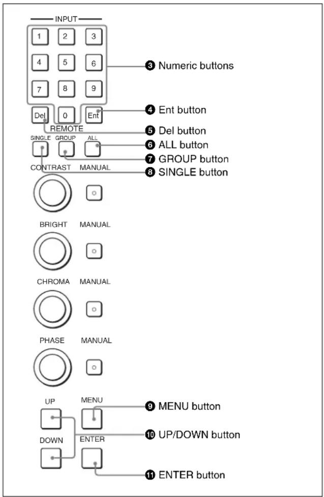
Remote connection
1 Set a different IP address to each monitor. 2 Set a different monitor ID No. to each monitor and if necessary, group ID No. 3 Select the connection mode by pressing the SINGLE, GROUP or ALL button.
The lamp corresponding with the pressed button flashes and lights after recognizing the monitor.
4 Select the monitor ID No. for the single connection mode or group ID No. for the group connection mode by pressing the UP/DOWN or numeric button.
Up to 99 is entered as the monitor ID or group ID No.
5 Press the ENTER ⑪ or Ent ④ button to confirm the setting.
The monitor ID No., group ID No. or ALL is displayed in the display window.
After setting steps 1 to 2, follow steps 3 to 5 for the remote connection.
Notes
- When no assigned monitor ID No. or group ID No. is selected, setting is not changed and the previous connection status is maintained.
- When there is same monitor ID No., the ID No. with the lower IP address is selected.
- When the different monitor ID No. is set but the same IP address as that of another monitor is set, the monitor cannot be connected to the network.
- To remotely control monitors connected in the network, the MONITOR ID, GROUP ID or IP address of monitors should be correctly set in the NETWORK menu and NETWORK SETTINGS menu of the SYSTEM CONFIGURATION menu. Also, the IP address of the monitor should be correctly set in the NETWORK SETTINGS menu of the CONTROLLER menu.
For information about the NETWORK menu and NETWORK SETTINGS menu, see “System Configuration – SYSTEM CONFIGURATION Menu” on page 39.
For information about the NETWORK SETTINGS menu, see “Setting the Controller-CONTROLLER Menu” on page 51.
Selecting the Default Settings
BVM-A14F5M only
When you turn on the unit for the first time after purchasing it, select the area where you intend to use this unit from among the options. When the area is set, the color temperature of CH1 to CH30 is set to the default value of each area.
| Color temperature | |
| JAPAN D93 | |
| OTHER AREA D65 | |
1 Turn on the power.
The SELECT SETTING screen appears.

2 Select the area where you intend to use the unit by using the menu operation buttons (see page 22).
Menu
2
Chapter
Basic Menu Operations
Menu Operation Buttons
The functions of the menu operation buttons are described below.
| Button | Function |
| 1 Numeric buttons | Enters the numerical values. |
| 2 Ent button | Executes the items selected and settings. |
| 3 Del button | Deletes the values and characters entered. |
| 4 PHASE knob | By turning this knob clockwise, the cursor moves upward. In setting mode, increases the setting and adjustment values (has the same function as UP button). By turning this knob counterclockwise, the cursor moves downward. In setting mode, decreases the setting and adjustment values (has the same function as DOWN button). |
| 5 MENU button | Displays the menus. Goes back to the menu of the upper level (on the Main Menu, goes back to the normal picture). |
| 6 UP button | Moves the cursor upward. In setting mode, increases the setting and adjustment values. |
| 6 DOWN button | Moves the cursor downward. In setting mode, decreases the setting and adjustment values. |
| 7 ENTER button | Executes the items selected and settings. |
Displaying the Menu
Press the MENU button.
The main menu is displayed on the screen.

When you select one item on the main menu, the level 1 menu corresponding to the selected item on the main menu appears.
For information about the items on the main menu, see "Menu Structure" on page 26.
Note
Menu settings displayed in blue cannot be changed.
About menu numbers
For purposes of explanation in this manual, the menu number is used. The alphabet determines the classification of the menu on the main menu, and the numbers determine the level and the order. These menu numbers are not shown on the screen.

Note
Only when the explanation is required, the menu number is used. The menu number is not counted when explanation is not required.
Menu Operation
Follow the steps described below to display the menu and perform the adjustment or setup you wish.
1. Press the MENU button.
The main menu is displayed.
2. Using the UP or DOWN button or PHASE knob, move the cursor to the desired item. (Example: select the INPUT CONFIGURATION... menu by pressing the DOWN button.)

3. Press the ENTER button or Ent button.
The Level 1 of the selected menu is displayed.

4. Repeat steps 2 and 3 until the desired menu is displayed.
For more information about setting and adjustments, see below.
![INPUT CONFIGURATION CH01 APERTURE OFF VALUE YC SEP ---. NTSC COMB FILTER --- MARKER DISPLAY OFF - MODE... H PHASE 000 CHANNEL NAME... COPY FROM... [↑] indicates that the menu continues onto next page. [↓] indicates that the menu is continued from previous page. 000 Selects from various options. Ente…](/content/2026/06/1389461/images/853795c1205a1b591af850935f3b991922deae67e049d54516177c37351a78e2.jpg)
To abort menu operation
Press the MENU button. The menu of the upper level is displayed.
The setting or adjustment being performed is canceled, and data loading or saving is aborted.
If "NG" or "ERROR" appears during menu operation
Press the MENU button to return to the menu in use.
Choosing one of two or more selections
Selecting in setting mode
1 Using the UP or DOWN button or PHASE knob, move the cursor to the desired item and press the ENTER or Ent button.
The selected item is displayed in yellow text and set to setting mode.

2 Using the UP or DOWN button or PHASE knob, change the setting. 3 Press the ENTER or Ent button.
The setting is confirmed (The item is displayed in white text again).
Selecting from the setting list
1 Using the UP or DOWN button or PHASE knob, move the cursor to the desired item in the setting list.

The display returns to the menu of the upper level, and the selected setting is executed.
Entering a numerical value
1 Using the UP or DOWN button or PHASE knob, move the cursor to the desired item and press the ENTER or Ent button.
The selected item is displayed in yellow text and set to setting mode.
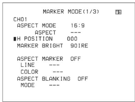
2 Set the value in one of the following three ways:
- Enter the value directly using the numeric keypad and press the ENTER or Ent button.
- Select the value using the UP or DOWN button.
- Select the value using the PHASE knob.
3 Press the ENTER or Ent button.
The setting is confirmed (The item is displayed in white text again).
Entering characters
1 Display the setting menu and set the cursor to NEW NAME using the UP or DOWN button or PHASE knob.

2 Press the ENTER or Ent button.
“?” is displayed in yellow. The “?” indicates the position where character input is possible.

3 Select the character you wish to enter using the UP or DOWN button or PHASE knob.
When you press the UP button, or turn the PHASE knob clockwise, the characters and symbols appear in the order shown below.
If you press the DOWN button or turn the PHASE knob counterclockwise, the characters and symbols appear in the reverse order described above.
The usable symbols are limited depending on the menu.
“(space)” is not used as a first character of a sentence.
4 Press the ENTER or Ent button.
The selected character is entered.

5 Repeat steps 3 and 4 until all the characters are entered, then press the ENTER or Ent button.
The selected characters are confirmed, and the display returns to the menu of the previous level.
To correct the entered character
Press the Del button on the numeric keypad. The character on the left side of the “?” (in yellow) is deleted.
Menu Structure
The main menu and Level 1 are shown below.
Detailed information on the menu levels is described at the
top of each menu explanation.

| Main menu Level 1 Functions | ||
| PICTURE ADJ A Adjusts the picture. (page 28) | ||
| PRESET VALUE Selects the preset data to be adjusted. (page 28) | ||
| AUTO A1 Sets the chroma/phase/matrix automatically. (page 29) | ||
| MANUAL ADJUST A2 Sets the preset values for the phase/chroma/brightness/contrast with the MANUAL adjustment knob. (page 29) | ||
| COPY FROM A3 Copies the other picture preset data. (page 30) | ||
| COLOR TEMP ADJ B | Adjusts the color temperature. (page 30) | |
| PRESET VALUE Selects the color temperature data to be adjusted. (page 31) | ||
| MANUAL B1 Sets the color temperature with the MANUAL knob. (page 31) | ||
| AUTO B2 Sets the color temperature automatically. (page 32) | ||
| COPY FROM B3 Copies the other color temperature. (page 33) | ||
| RESTORE FACTORY DATA B4 Resets the color temperature. (page 33) | ||
| ANALYZE B5 Reads the color temperature and luminance value. (page 33) | ||
| INPUT CONFIGURATION C | Sets the data for the input signals. (page 34) | |
| CHxx Current channel is indicated. (page 35) | ||
| FORMAT C1 Selects the signal format. (page 36) | ||
| SLOT NO Selects the slot number. (page 35) | ||
| INPUT NO Selects the input connector number. (page 35) | ||
| SCREEN ASPECT Sets the aspect ratio. (page 35) | ||
| SCAN SIZE Sets the scan size. (page 35) | ||
| SYNC MODE Sets the sync signal. (page 35) | ||
| COLOR TEMP Selects the color temperature. (page 35) | ||
| PICTURE PRESET Selects the picture adjustment preset. (page 36) | ||
| MATIRIX C2 Sets the matrix of the signal system. (page 37) | ||
| APERTURE Chooses whether to use aperture adjustment or not. (page 36) | ||
| VALUE Enters the aperture adjustment value. (page 36) | ||
| YC SEP Selects Y/C separation filter. (page 36) | ||
| NTSC COMB FILTER Sets the NTSC COMB ilter. (page 36) | ||
| MARKER DISPLAY Chooses whether or not to display the marker. (page 36) | ||
| MODE C3 Sets the marker aspect, safe area, safe title, etc. (page 37) | ||
| H PHASE Adjusts the horizontal picture position. (page 36) | ||
| CHANNEL NAME C4 Sets the channel name. (page 38) | ||
| COPY FROM C5 Copies the data from other channel. (page 39) | ||
| Main menu | Level 1 | Functions |
| SYSTEM CONFIGURATION D | Sets the system of the remote control function, LAN, etc. (page 39) | |
| NETWORK D1 | Sets the IP address, subnet mask and default gateway. (page 40) | |
| PARALLEL REMOTE D2 | Sets the remote control function. (page 41) | |
| POWER D3 | Sets the condition of the monitor when the main power or I/○ switch is turned on. (page 41) | |
| BLANKING SETTINGS D4 | Adjusts the data for the picture. (page 42) | |
| ON SCREEN SET D5 | Sets the data for the screen display. (page 42) | |
| PASSWORD D6 Sets the passwords for the menu. (page 42) | ||
| MAINTENANCE D7 Displays the menu for maintenance. (page 42) | ||
| INSTALLATION SETTINGS E | Sets the initial value of landing, alignment, etc. (page 43) | |
| LANDING ADJUST E1 | Corrects the shift of beam landing caused by the earth's magnetism. (page 44) | |
| ALIGNMENT E2 | Adjusts the position and size of the picture. (page 44) | |
| DIGITAL UNIFORMITY ADJ E3 | Adjusts the color unevenness of the CRT. (page 45) | |
| FILE MANAGEMENT F | Saves, copies and deletes the system data. (page 47) | |
| SAVE TO F1 | Writes the data. (page 48) | |
| COPY FROM F2 | Reads or copies the data. (page 48) | |
| DELETE F3 Deletes the file. (page 48) | ||
| DATA MAINTENANCE F4 | Services the system data. (page 48) | |
| STATUS G | Displays the information about the monitor or options installed in the monitor. (page 49) | |
| CH STATUS G1 | Displays the information of the used channel. (page 50) | |
| SLOT STATUS G2 | Displays the data about the optional board installed in the option slot 1 to 3. (page 50) | |
| MODEL NAME | Displays the model name. (page 50) | |
| SERIAL NO | Displays the serial number. (page 50) | |
| SOFTWARE VERSION | Displays the software version. (page 50) | |
| OPERATION TIME | Displays the operation time. (page 50) | |
| CRT TURN ON TIME | Displays how long the CRT is used. (page 50) | |
| IP ADDR | Displays the IP address of the monitor. (page 50) | |
| CONTROLLER STATUS G3 | Displays the information on the controller (controlled moitor). (page 50) | |
| CONTROLLER H | When the Monitor Control Unit BKM-15R is connected, sets the network of the controller. (page 51) | |
| MONITOR ID DISPLAY H1 | Sets the display method of the monitor select display window. (page 51) | |
| NETWORK SETTING H2 | Displays the NETWORK SETTING menu. (page 51) | |
| NETWORK SW | Sets the Ethernet connections. (page 51) | |
| SNMP SETTINGS H3 | Sets CONTACT, NAME, LOCATION and TRAP. (page 51) | |
| KEY PROTECT I | Sets whether or not to lock the buttons on the monitor. (page 52) | |
A Picture Adjustment – PICTURE ADJ Menu
Overview
The auto chroma/phase/matrix adjustment and preliminary adjustment of contrast/brightness/chroma/phase to set the preset value to each knob are carried out.
- Selecting the preset data to be adjusted (PRESET VALUE menu)
- Auto chroma/phase/matrix adjustment (AUTO... menu)
An external color bar signal is necessary.
Matrix data is changed or reset to the default setting.
- Adjustment of the preset values for phase/chroma/brightness/contrast with the MANUAL knobs (MANUAL ADJUST menu)
- Copying data (COPY FROM... menu)
Other data in the monitor, other monitors, or “Memory Stick” is copied.
Structure of the PICTURE ADJ Menu
| Level 1 | Level 2 | Level 3 |
| PRESET VALUE | ||
| AUTO... A1 | AUTO ADJUST A11 | |
| MATRIX VALUE | ||
| MATRIX RESET | ||
| COLOR BAR | ||
| MANUAL ADJUST A2 | ||
| COPY FROM... A3 PRESET VALUE... A31 | ||
Setting Lists in the PICTURE ADJ Menu
This section explains the setting lists displayed in the menu.
How to read the setting lists
- For purposes of explanation, each setting list is preceded by a menu number. These numbers are not displayed on the screen.
For more information on the menu number, see “About menu numbers” on page 23.
- The arrow mark (=>) refers you to another setting list that appears after you make the setting, or to an operation that is to be carried out as a result of the setting.
A PICTURE ADJ menu
PRESET VALUE: The picture adjustment preset data set in the INPUT CONFIGURATION menu is displayed. To change the picture adjustment preset data to be adjusted, select from PRESET1, PRESET2, PRESET3, PRESET4, and PRESET5.
When the picture adjustment preset data is changed
When the preset data is changed and you press the MENU button to return to the main menu, the following message appears to confirm the setting.
CHANGE INPUT CONFIG?
PRESET VALUE
PRESETX (previous preset data) → PRESETX (new preset data)
OK: Press the ENTER or Ent button to change the preset data.
The preset data set in the INPUT
CONFIGURATION menu is changed to the new data.
CANCEL: Press the MENU button to cancel changing the preset data and to return to the main menu.
The setting of the preset data is remained but the data set in the INPUT CONFIGURATION menu is not changed.
For information about the INPUT
CONFIGURATION menu, see “Setting the Input Configuration – INPUT CONFIGURATION Menu” on page 34.
AUTO...: Set the chroma/phase/matrix automatically.
A1
MANUAL ADJUST: Set the picture adjustment preset values for the phase/chroma/brightness/contrast with the MANUAL knobs. → A2
COPY FROM...: Copy the other picture preset data. → A3
A1 AUTO... menu
Set the automatic adjustment of chroma/phase/matrix. The chroma/phase/matrix data is reset to the default setting (1000).
AUTO ADJUST: Start automatic adjustment. ⇒A11
MATRIX VALUE: The matrix data set in the INPUT CONFIGURATION menu is displayed. To change the matrix data to be adjusted, select from ITU601, SMPTE 240M, ITU709 or USER 1 to 5.
When ITU601, SMPTE 240M or ITU709 data is changed, they are displayed as ITU601*, SMPTE 240M* or ITU709*.
When the matrix data is changed
When the matrix data is changed and you press the MENU button to return to the main menu, the following message appears to confirm the setting.
CHANGE INPUT CONFIG?
MATRIX VALUE (1080/720)
Previous matrix data → New matrix data MATRIX VALUE (1035)
Previous matrix data → New matrix data MATRIX VALUE (480/576)
Previous matrix data → New matrix data
OK: Press the ENTER or Ent button to change the matrix data.
The matrix data set in the INPUT
CONFIGURATION menu is changed to the new data.
CANCEL: Press the MENU button to cancel changing the matrix data and return to the main menu.
The setting of the matrix data is retained, but the matrix data set in the INPUT CONFIGURATION menu is not changed.
For information about the INPUT
CONFIGURATION menu, see “Setting the Input Configuration – INPUT CONFIGURATION Menu” on page 34.
MATRIX RESET: Reset the matrix data to the default setting.
When the setting of USER1 to 5 or the default setting is used, this menu is not selectable.
The following confirmation message appears.
RESET FACTORY DATA?
OK: To reset the data, press the ENTER (Ent) button.
CANCEL: To cancel, press the MENU button.
COLOR BAR: Select the color bar signal.
FULL FIELD 8: 100% full-field 8-color bar (white, yellow, cyan, green, magenta, red, blue, and black) (Default)
SMPTE: SMPTE standard color bar
EIA: EIA standard color bar (effective for 480/60I and 575/50I signals only)
MULTI FORMAT: Color bar standardized by SMPTE RP219/ARIB STD-B28
Notes
- When you execute the AUTO menu, the EXT SYNC button should be set to OFF (INT SYNC). Setting it to ON (EXT SYNC) will cause an error and abort the auto adjustment procedure.
- When the signal format set in the FORMAT menu of the INPUT CONFIGURATION menu is 4:4:4 RGB or RGB, MATRIX VALUE or MATRIX RESET is not selectable.
A11 AUTO ADJUST menu
Start automatic adjustment. (It may take some time to adjust automatically.)
To cancel adjustment
Press the MENU button.
A2 MANUAL ADJUST menu
Adjust values by turning the PHASE, CHROMA, BRIGHT, and/or CONTRAST knobs. After adjustment, press the ENTER or Ent button to confirm the adjusted values.
PHASE: xxxx
CHROMA: xxxx
BRIGHT: xxxx
CONTR: xxxx
When you want to erase characters from the screen while adjusting manually
Press the CHAR OFF button. The characters disappear. To display characters, press the CHAR OFF button again.
To reset the setting to the default
Press the corresponding MANUAL button. The adjusted value is reset to 1000 (default).
To cancel adjustment
Press the MENU button. The adjustment data is cleared.
To confirm adjustment
Press the ENTER (Ent) button.

A3 COPY FROM... menu
Copy picture adjustment preset data.
PRESET VALUE...: Copy other data in the monitor. →A31
OTHER MONITOR...: Copy data from another monitor. → A32
MEMORY STICK...: Copy data from a file in the "Memory Stick". → A33
Note
Matrix data is not copied.
A31 PRESET VALUE... menu
Copy data from another channel or common data.
Select one from among PRESET1, PRESET2, PRESET3, PRESET4 and PRESET5.
A32 OTHER MONITOR... menu
Assign the ID No. of the source monitor.
MONITOR ID...: Enter the ID No. of the monitor. →A321
A321 OTHER MONITOR menu
Copy data from another selected monitor.
Select one from among PRESET1, PRESET2, PRESET3, PRESET4 and PRESET5.
A33 MEMORY STICK... menu
Select a file in the source "Memory Stick". → A331
A331 MEMORY STICK menu
Copy data in the selected file.
Select one from among PRESET1, PRESET2, PRESET3, PRESET4 and PRESET5.
B Adjusting the Color Temperature – COLOR TEMP ADJ Menu
Overview
The color temperature is adjusted.
Use the factory setting value or the adjusted value as a base value to shorten the adjustment time.
- Selecting the preset data to be adjusted (PRESET VALUE menu)
- Knob adjustment (MANUAL... menu) You can adjust the bias and gain with the MANUAL knobs. • Automatic adjustment (AUTO... menu)
You can use the following probes for automatic adjustment of color temperature. Except for the Sony BKM-14L, a cable is required to connect the color analyzer to the monitor.
| Manufacturer Probe Model | Name |
| SONY BKM-14L (no cable required) | |
| KONICA MINOLTA CA-100, CA-100plus | |
| DK-TECHNOLOGIES PM 5639 | |
| THOMA TF6 | |
| UDT INSTRUMENTS SLS 9400-FC | |
For more information about the cable specification required and about the connection, see “Connection Cable Specifications for Color Temperature Probes” on page 59.
- Copying other data (COPY FROM... menu)
Other data in this monitor, other monitors or “Memory Stick” is copied.
- Resetting to the default setting (RESTORE FACTORY DATA menu)
Color temperature data is reset to the default setting.
- Displaying the measured color coordinate and luminance (ANALYZE menu)
The color coordinate and luminance are measured by BKM-14L.
Before adjusting the color temperature
We recommend that you perform automatic adjustment using the AUTO... [A1] menu of the PICTURE ADJ menu.
Structure of the COLOR TEMP ADJ Menu
| Level 1 Level 2 | Level 3 | |
| PRESET VALUE | ||
| MANUAL... [B1] | MANUAL ADJUST [B11] | |
| ORIGINAL VALUE | ||
| SIGNAL | ||
| CONT/BRT HOLD | ||
| AUTO... [B2] | AUTO ADJUST [B21] | |
| TARGET COLOR TEMP | ||
| X | ||
| Y | ||
| LOW LIGHT (20 IRE) | ||
| HIGH LIGHT (100 IRE) | ||
| PROBE | ||
| CONT/BRT HOLD | ||
| COPY FROM... [B3] | PRESET VALUE... [B31] | |
| OTHER MONITOR... [B32] | OTHER MONITOR... [B321] | |
| MEMORY STICK... [B33] | MEMORY STICK [B331] | |
| RESTORE FACTORY DATA [B4] | ||
| ANALYZE [B5] |
Setting Lists in the COLOR TEMP ADJ Menu
This section explains the setting lists displayed in the menu.
How to read the setting lists
- For purposes of explanation, each setting list is preceded by a menu number. These numbers are not displayed on the screen.
For more information on the menu number, see “About menu numbers” on page 23.
- The arrow mark (⇒) refers you to another setting list that appears after you make the setting, or to an operation that is to be carried out as a result of the setting.
B COLOR TEMP ADJ menu
PRESET VALUE: The color temperature data set in the INPUT CONFIGURATION menu is displayed. To change the color temperature data to be adjusted, select from D93, D65, D61, USER1, USER2, USER3, USER4 and USER5. When D93, D65 or D61 data is changed, they are displayed as D93*, D65* or D61*.
When the color temperature data is changed
When the preset data is changed and you press the MENU button to return to the main menu, the following message appears to confirm the settings.
CHANGE INPUT CONFIG?
COLOR TEMP PRESET
DXX* → USERX
(previous color temp value) → (new color temp value)
OK: Press the ENTER or Ent button to change the color temperature data.
The color temperature data set in the INPUT CONFIGURATION menu is changed to the new data.
CANCEL: Press the MENU button to cancel changing the color temperature data and to return to the main menu.
The setting of the color temperature data is retained, but the color temperature data set in the INPUT CONFIGURATION menu is not changed.
For information about the INPUT CONFIGURATION menu, see “Setting the Input Configuration – INPUT CONFIGURATION Menu” on page 34.
MANUAL...: Adjust the color temperature with the MANUAL knob. ⇒ B1
AUTO...: Adjust the color temperature automatically ⇒ B2
COPY FROM...: Copy the other color temperature. → B3
RESTORE FACTORY DATA: Reset the color temperature to the default setting. ⇒ B4
ANALYZE: Read the color temperature and luminance value. ⇒ B5
B1 MANUAL... menu
MANUAL ADJUST: Adjust the gain and bias with the knobs. ⇒ B11
ORIGINAL VALUE: Set the initial value. Select one from among D93, D65, D61, USER1, USER2, USER3, USER4 and USER5. When D93, D65 or D61 data is changed, they are displayed as D93*, D65* or D61*.
SIGNAL: Select the white signal to be used for adjustment.
INT: Use an internal signal. Simultaneously with the adjustment of the gain and bias, the 100 IRE and 20 IRE signals are automatically switched.
EXT: Use an external input signal. When adjusting the gain and bias, input the proper signal (default).
CONT/BRT HOLD: Select the contrast and brightness settings to the center or adjusted value by the manual adjustment of the white balance (OFF or ON).
ON: The contrast and brightness are set to the value before adjusting (default).
OFF: The contrast and brightness are set to the center value (1000) when the white balance is adjusted.
The contrast and brightness are not changed after adjusting (center value: 1000).
B11 MANUAL ADJUST menu
Adjust the gain and bias. To shift between gain adjustment and bias adjustment, press the UP/DOWN buttons.
Knobs for each adjustment
After adjustment, press the ENTER or Ent button to confirm the setting.
RED: CONTRAST KNOB (Adjust the R gain or bias with the CONTRAST knob.)
GREEN: BRIGHT KNOB (Adjust the G gain or bias with the BRIGHT knob.)
BLUE: CHROMA KNOB (Adjust the B gain or bias with the CHROMA knob.)
LUMINANCE: PHASE KNOB (Adjust luminance with the PHASE knob.)
To reset RED/GREEN/BLUE to the value before adjustment
When you are adjusting the gain or bias using the MANUAL adjustment knobs, you can reset the setting to the one before adjustment by pressing the corresponding MANUAL button.
To reset all of the settings at the same time, press the MANUAL button of PHASE.
Note
You cannot reset the setting after you press the ENTER or Ent button.
To cancel adjustment
Press the MENU button. The adjustment data is cleared.
To confirm adjustment
Press the ENTER (Ent) button.
Using the COL TEMP (short-cut) button
You can display the MANUAL menu that corresponds to the color temperature set to the image on the screen.
B2 AUTO... menu
Set the color temperature automatically.
AUTO ADJUST: Start adjustment. ⇒ B21
TARGET COLOR TEMP: Select the adjustment value to be used.
You can select one from among D93, D65, D61 and ANY.
X: Enter the x coordinate.
Y: Enter the y coordinate.
LOW LIGHT (20IRE): Enter the luminance (cd/m 4 ) for low light.
HIGH LIGHT (100IRE): Enter the luminance (cd/m²) for high light.
PROBE: Select the probe to adjust the color temperature automatically.
Selection of the probe
BKM-14L: Use BKM-14L.
CA-100: Use CA-100 or CA-100plus.
- If you cannot execute an AUTO ADJUST menu operation when using the Sony BKM-14L probe, try again after disconnecting and reconnecting the probe.
- When using the KONICA MINOLTA CA-100plus probe, set the RS-232C communication environment to CA-100 compatible mode (BAUD RATE setting: 9600 bps).
- When using the THOMA TF6 probe, set the TF6 PRINT menu to off.
CONT/BRT HOLD: Select the contrast and brightness settings to the center or adjusted value after the auto adjustment of the white balance (OFF or ON). The contrast and brightness are set to the center value (1000) when the white balance is adjusted automatically.
ON: The contrast and brightness are set to the value before adjusting (default).
OFF: The contrast and brightness are set to the center value (1000) after adjusting.
To start adjustment, proceed as follows.
When you use the previously adjusted values for adjustment, you can start adjustment by selecting AUTO ADJUST without performing step ①, step ② and step ③.
①Select the color temperature to be used in TARGET COLOR TEMP.
When ANY is selected, enter the values of the CIE 1931 color system x and y coordinates.
②Enter values for LOW LIGHT and HIGH LIGHT.
③Select the probe (default setting is BKM-14L).
④Select AUTO ADJUST.
B21 AUTO ADJUST menu
This menu is displayed when AUTO ADJUST is selected in the B2 AUTO... menu.
The following message appears.
SET PROBE ON CURSOR
Attach the probe on the center of the CRT to start automatic adjustment. (It may take some time to adjust automatically.)
To cancel/stop the adjustment
Press the MENU button.
B3 COPY FROM... menu
Copy other matrix data.
PRESET VALUE...: Copy other data in this monitor. →B31
OTHER MONITOR...: Copy data from another monitor. → B32
MEMORY STICK...: Copy data from a file in the "Memory Stick". → B33
B31 PRESET VALUE... menu
Select the data to be copied.
Select one from among D93, D65, D61, USER1, USER2, USER3, USER4 and USER5.
D93: Copy the color temperature of D93.
D65: Copy the color temperature of D65.
D61: Copy the color temperature of D61.
USER1 to 5: Copy the color temperature of USER1 to 5.
When D93, D65 or D61 data is changed, they are displayed as D93*, D65* or D61*.
B32 OTHER MONITOR... menu
Assign the ID No. of the source monitor.
MONITOR ID...: Enter the ID No. of the monitor. →B321
B321 OTHER MONITOR... menu
Select the data from another selected monitor.
Select one from among D93, D65, D61, USER1, USER2, USER3, USER4 and USER5.
D93: Copy the color temperature of D93.
D65: Copy the color temperature of D65.
D61: Copy the color temperature of D61.
USER1 to 5: Copy the color temperature of USER1 to 5.
When D93, D65 or D61 data is changed, they are displayed as D93*, D65* or D61*.
B33 MEMORY STICK... menu
Select the file in the source "Memory Stick". ⇒ B331
B331 MEMORY STICK menu
Select the data from a file in the "Memory Stick"
Select one from among D93, D65, D61, USER1, USER2, USER3, USER4 and USER5.
D93: Copy the color temperature of D93.
D65: Copy the color temperature of D65.
D61: Copy the color temperature of D61.
USER1 to 5: Copy the color temperature of USER1 to 5.
When D93, D65 or D61 data is changed, they are displayed as D93*, D65* or D61*.
B4 RESTORE FACTORY DATA menu
Reset the color temperature to the default setting.
You cannot select this when USER1 to 5 is selected or the setting is the default value. The following message appears to confirm the data reset operation.
RESTORE FACTORY DATA?
OK: Press the ENTER or Ent button to reset the data.
CANCEL: Press the MENU button to cancel the reset operation.
B5 ANALYZE menu
Perform operation according to the message to enable the BKM-14L to read the color system and luminance value.
SET PROBE ON CURSOR
Attach the probe on the center of the CRT.
Once the probe has carried out calibration, it can start to analyze the monitor's performance.
To cancel the analysis
Press the MENU button.
Notes
- Do not cut the R, G, or B beam or display the marker before carrying out calibration of BKM-14L. It may cause non-detection of BKM-14L.
- During analyzing, do not disconnect BKM-14L from the OPTION connector. If nothing has been displayed on the monitor, press the MENU button. The display returns to the COLOR TEMP ADJ menu.
C Setting the Input Configuration – INPUT CONFIGURATION Menu
Overview
Data pertaining to the input signals are set with this menu. Set the input data for each channel.
A channel number (1 to 30) is entered with the numeric keypad.
The following data can be set with the INPUT CONFIGURATION menu.
- Assigning the signal format (FORMAT...menu)
- Assigning the slot number (SLOT NO menu)
- Assigning the input connector number (INPUT NO menu)
- Setting the aspect ratio (SCREEN ASPECT menu)
- Selecting the scan size (SCAN SIZE menu)
- Selecting the sync mode (SYNC MODE menu)
- Setting the color temperature (COLOR TEMP menu)
- Selecting the picture preset (PICTURE PRESET menu)
- Setting the matrix (MATRIX... menu)
- Activating/deactivating the aperture adjustment (APERTURE menu)
- Assigning the aperture value (VALUE menu)
- Selecting the Y/C separation filter (YC SEP menu)
- Selecting the NTSC COMB filter (NTSC COMB FILTER menu)
- Selecting the marker display (MARKER DISPLAY menu)
- Selecting the marker mode (MODE... menu)
- Adjusting H phase (H PHASE menu)
- Assigning the channel name (CHANNEL NAME... menu)
- Copying from other data (COPY FROM... menu)
Channels 80 to 89 assignment
The channel numbers from 80 to 89 are assigned to switch the signal system of the internal signals.
The channels 80 to 89 can be selected after selecting channels 91 to 97 and the internal signal of the selected signal system is output.
Channels 91 to 97 assignment
The channel numbers from 91 to 97 are assigned to internal signals. The internal signal of the last signal system is displayed. When the power is ON and the picture is displayed by the internal signal, the signal system is 480/60I.
091: PLUGE signal (Picture Line Up Generating Equipment)
092: 20% gray signal
093: 100% white signal
094: five-step gray scale signal
095: cross-hatch signal
096: dot signal
097: 0% black signal
Assigning slot and connector numbers
Set which input connector on which slot will be assigned to the current channel.
The slot number is as follows.
OPTION1 (outside of the monitor)
OPTION2
OPTION3 (inside of the monitor)
The input number is as follows.
When BKM-61D is installed (signal SDI D1, SDI D1/D2 AUTO, SDI D2 NTSC or SDI D2 PAL): DIGITAL1 or 2
When BKM-61D is installed (analog composite signal COMPOSITE AUTO, NTSC, PAL, PAL-M or SECAM): COMPOSITE1, 2 or 3
When BKM-62HS is installed (signal SDI HD/D1
AUTO, HD-SDI or SDI D1): DIGITAL1 or 2
Notes
When FORMAT... is set to the following, you cannot select the input number.
- when BKM-61D is installed and Analog Y/C signal is input
- when BKM-62HS is installed and Dual Link HD-SDI signal is input
- when BKM-68X is installed and Analog Component or Analog RGB signal is input
Structure of the INPUT CONFIGURATION Menu
| Level 1 Level 2 Level 3 | ||
| CHxx | ||
| FORMAT... [C1]SDI/HD | -SDI... [C11] | |
| DUAL LINK HD-SDI... [C12] | ||
| COMPOSITE... [C13] | ||
| YC... [C14] | ||
| COMPONENT... [C15] | ||
| SLOT NO | ||
| INPUT NO | ||
| SCREEN ASPECT | ||
| SCAN SIZE | ||
| SYNC MODE | ||
| COLOR TEMP | ||
| PICTURE PRESET | ||
| MATRIX... [C2] | ||
| APERTURE | ||
| VALUE | ||
| YC SEP | ||
| NTSC COMB FILTER | ||
| MARKER DISPLAY | ||
| MODE... [C3] | ||
| H PHASE | ||
| CHANNEL NAME... [C4] | ||
| COPY FROM... [C5] | OTHER CH... [C51] | |
| OTHER MONITOR... [C52] | OTHER MONITOR [C521] | |
| MEMORY STICK... [C53] | MEMORY STICK [C531] | |
Setting Lists in the INPUT CONFIGURATION Menu
This section explains the setting lists displayed in the menu.
How to read the setting lists
- For purposes of explanation, each setting list is preceded by a menu number. These numbers are not displayed on the screen.
For more information on the menu number, see “About menu numbers” on page 23.
- The arrow mark (⇒) refers you to another setting list that appears after you make the setting, or to an operation that is to be carried out as a result of the setting.
© INPUT CONFIGURATION menu
This menu is composed by the INPUT CONFIGURATION (1/2) and INPUT CONFIGURATION (2/2) menus.
Set input signal data for each channel.
INPUT CONFIGURATION (1/2) menu
CHxx: Current channel is indicated. The settings below will be stored as information about the signal to be connected to this channel.
FORMAT...: Select the input signal type. C1
SLOT NO: Enter the option slot number (OPTION1 to 3).
INPUT NO: Enter the input connector number.
SCREEN ASPECT: Select the aspect ratio (16:9, 4:3, LAST).
16:9: Set the aspect ratio to 16:9 (default).
4:3: Set the aspect ratio to 4:3.
LAST: Use the previous setting.
SCAN SIZE...: Select the scan size (NORMAL, UNDER, LAST).
NORMAL: Set the scan size to over scan (default).
UNDER: Set the scan size to under scan.
LAST: Use the previous setting.
SYNC MODE: Select the sync signal (INT, EXT, LAST).
INT: Use an internal sync signal (default).
EXT: Use an external sync signal.
LAST: Use the previous setting.
COLOR TEMP: Select the color temperature (D93, D65, D61 or USER1 to 5).
When D93, D65 or D61 data is changed, they are displayed as D93*, D65* or D61*.
PICTURE PRESET: Select the picture adjustment preset (PRESET1 to 5). (default setting is PRESET1)
MATRIX...: Displays the MATRIX menu. Set the matrix of each signal format. ⇒ C2
INPUT CONFIGURATION (2/2) menu
APERTURE: Choose whether or not to use aperture adjustment (OFF, ON, LAST).
OFF: Do not use aperture adjustment (default).
ON: Use aperture adjustment.
LAST: Use the previous setting.
VALUE: Enter the aperture adjustment value (0 to 200) (default setting is 000).
YC SEP: Select Y/C separation filter.
COMB: Use the comb filter (default).
BPF/TRAP: Select BPF/TRAP.
NTSC COMB FILTER: Select the NTSC COMB FILTER (3 LINES or 3D) (default setting is 3 LINES).
MARKER DISPLAY: Choose whether or not to display the marker (OFF or ON) (default setting is OFF).
MODE...: Display the MARKER MODE menu. Set the marker aspect, safe area, safe title, etc. => C3
H PHASE: Set the horizontal picture position (-100 to +100*) (default setting is 000).
* When the setting value is out of range, the display is changed but the horizontal position of the picture is not changed.
CHANNEL NAME...: Display the CHANNEL NAME menu. Give the channel a name. => C4
COPY FROM...: Display the COPY FROM menu. Copy other channel data. => C5
C1 FORMAT... menu
Select the signal format.
SDI/HD-SDI...: Serial digital signal => C11
DUAL LINK HD-SDI...: Dual link HD-SDI signal => C12
COMPOSITE...: Analog composite signal => C13
YC...: Analog Y/C signal => C14
COMPONENT...: Analog component or RGB signal => C15
Note
If there is no input connector or decoder corresponding to a format, that format will not be selectable (the cursor will skip over that item).
C11 SDI/HD-SDI... menu
Select the serial digital signal format (SDI or single link HD-SDI).
HD-SDI/D1 AUTO: Select when BKM-62HS is installed.
HD SDI: Select when BKM-62HS is installed.
D1: Select when BKM-61D or BKM-62HS is installed.
D1/D2 AUTO: Select when BKM-61D is installed.
D2 NTSC: Select when BKM-61D is installed.
D2 PAL: Select when BKM-61D is installed.
NTSC SETUP LEVEL: Select the NTSC SETUP LEVEL (0 % or 7.5 %) (default setting is 7.5 % for BVM-A14F5U, 0 % for BVM-A14F5M/A14F5A).
FILTER SW: Set the Y/C separation filter (OFF or ON) when the picture is set to black and white mode (default setting is OFF).
ACC SW: Select the auto chroma control ON or OFF (default setting is OFF).
1080/60I or 1035/60I is selected automatically for the HD-SDI 1125/60I input signal.
C12 DUAL LINK HD-SDI... menu
Select the dual link HD-SDI signal format when BKM-62HS is installed.
4:4:4 YPBPR
4:4:4 RGB
C13 COMPOSITE... menu
Select the composite signal format when BKM-61D is installed.
AUTO: The format of the input signal is detected and switched automatically. It will take a few seconds to detect the format of an input signal. It is recommended that a particular format be selected if it is determined.
NTSC
PAL
PAL-M
SECAM
NTSC SETUP LEVEL: Select the NTSC SETUP LEVEL (0 % or 7.5 %) (default setting is 7.5 % for BVM-A14F5U, 0 % for BVM-A14F5M/A14F5A).
FILTER SW: Set the Y/C separation filter (OFF or ON) when the picture is set to black and white mode (default setting is OFF).
ACC SW: Select the auto chroma control ON or OFF (default setting is OFF).
C14 YC... menu
Select the Y/C signal format when BKM-61D is installed.
AUTO: The format of the input signal is detected and switched automatically. It will take a few seconds to detect the format of an input signal. It is recommended that a particular format be selected if it is determined.
NTSC
PAL
PAL-M
SECAM
NTSC SETUP LEVEL: Select the NTSC SETUP LEVEL (0% or 7.5%) (default setting is 7.5% for BVM-A14F5U, 0% for BVM-A14F5M/A14F5A).
ACC SW: Select the auto chroma control ON or OFF (default setting is OFF).
C15 COMPONENT... menu
Select the component signal format or RGB signal format (YPBPR or RGB) when BKM-68X is installed.
COMPONENT LEVEL: Select the COMPONENT LEVEL (SMPTE/EBU-N10 or BETACAM) (default setting is SMPTE/EBU-N10).
BETACAM SETUP LEVEL: Select the BETACAM SETUP LEVEL (0% or 7.5%) (default setting is 7.5% for BVM-A14F5U, 0% for BVM-A14F5M/A14F5A).
1125/60I SYSTEM: Select the active lines (1080I (1080 active lines) or 1035I (1035 active lines)) when 1125/60I signal is input (default setting is 1080I).
C2 MATRIX... menu
Set the matrix for each signal system.
1080/720: Select the matrix data of 1080I and 720P (default setting is ITU709).
1035: Select the matrix data of 1035I (default setting is SMPTE 240M).
480/576: Select the matrix data of 480I, 480P, 575I and 576P (default setting is ITU601).
ITU601, SMPTE 240M, ITU709 or USER1 to 5 is selectable in each item.
When ITU601, SMPTE 240M or ITU709 data is changed, they are displayed as ITU601*, SMPTE 240M* or ITU709*.
Note
When the signal format set in the C1 FORMAT menu is 4:4:4 RGB or RGB, MATRIX menu is not selectable.
C3 MODE... menu
Set the marker aspect, safe area, safe title, etc. If a signal without the sync signal is input or the internal sync signal is used, this menu is not selectable.
MARKER MODE (1/3) menu
Set the marker aspect mode, aspect marker, blanking, etc.
ASPECT MODE: Set the marker aspect ratio of the picture. You can select one from among 16:9, 15:9, 14:9, 13:9, 4:3, 2.39:1, 2.35:1, 1.85:1, 1.66:1 and VARIABLE (default setting is 16:9).
ASPECT: Set when VARIABLE is selected in ASPECT MODE. Set 1.00 to 3.00 (default setting is 1.78).
H POSITION: Set the horizontal position of the marker. Set -100 to +100 (default setting is 000).
MARKER BRIGHT: Set the luminance of the marker. Set 90IRE or 40IRE (default setting is 90IRE). The data set in this menu is common to all the channels.
ASPECT MARKER: Select whether or not to display the safe area. Set to OFF (not display) or ON (display) (default setting is OFF).
LINE: Set the thickness of the aspect marker when ASPECT MARKER is set to ON. Set to THICK or THIN (default setting is THICK).
COLOR: Set the color of the aspect marker when ASPECT MARKER is set to ON. Set to WHITE, RED, GREEN, BLUE, YELLOW, CYAN or MAGENTA (default setting is WHITE).
ASPECT BLANKING: Select the blanking outside the area. Set to OFF (blanking is released) or ON (blanking) (default setting is OFF).
MODE: Set the blanking mode when ASPECT BLANKING is set to ON. Set BLACK (blanking) or HALF (half blanking) (default setting is HALF).

MARKER MODE (2/3) menu
Set the safe area marker or center marker.
SAFE AREA MARKER: Select whether or not to display the safe area.
Set to OFF (not display) or ON (display) (default setting is ON).
MODE: Select the display mode for safe area when SAFE AREA MARKER is set to ON.
Set to SHAPE A, SHAPE B or SHAPE C (default setting is SHAPE A).
SHAPE A
SHAPE B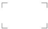
SHAPE C
AREA SIZE: Set the size of the safe area mode when SAFE AREA MARKER is set to ON. Set to 80%, 88%, 90%, 93% or VARIABLE (default setting is 80%).
WIDTH: Set the width of the safe area marker when AREA SIZE is set to VARIABLE. Set to 050 to 100(%) (default setting is 080).
HEIGHT: Set the height of the safe area marker when AREA SIZE is set to VARIABLE. Set to 050 to 100(%) (default setting is 080).
CENTER MARKER: Select whether or not to display the center marker. Set to OFF (not display) or ON (display) (default setting is OFF).
MODE: Select the display mode of the center marker when CENTER MARKER is set to ON. Set to SHORT or LONG (default setting is SHORT).
Note
The size of the safe area is as follows depending on the ASPECT MODE and 16:9 button ON/OFF setting.
Example: Safe area size 80%, ASPECT MODE 16:9 or 4:3 with 16:9 button ON with 16:9 button OFF ASPECT MODE 16:9

ASPECT MODE 4:3

MARKER MODE (3/3) menu
Set the safe title.
SAFE TITLE DISPLAY: Select whether or not to display the safe title.
Set to OFF (not display) or ON (display) (default setting is ON).
WIDTH: Set the width of the safe title when SAFE TITLE DISPLAY is set ON.
Set to 005 to 050(%) (default setting is 020).
HEIGHT: Set the height of the safe title when SAFE TITLE DISPLAY is set ON. Set to 005 to 050(%) (default setting is 010).
H POSITION: Set the horizontal position of the safe title when SAFE TITLE DISPLAY is set to ON. Set to 000 to 100(%) (default setting is 015).
V POSITION: Set the vertical position of the safe title when SAFE TITLE DISPLAY is set to ON. Set to 000 to 100(%) (default setting is 015).
C4 CHANNEL NAME... menu
Give the channel a name. Select a preset name, or enter a new one.
PROG: Program signal
EDIT: Signal from an editor
CAM: Camera signal
VTR: Signal from a VTR
PREV: Preview monitor
NEW NAME: Enter a new name. (Up to 20 characters can be entered and up to 8 characters from the head of the name are displayed in the INPUT CONFIGURATION menu).
C5 COPY FROM menu
Select the source to be copied from.
OTHER CH...: Copy other data in this monitor. →C51
OTHER MONITOR... : Copy data from another monitor. → C52
MEMORY STICK... : Copy data from a file in the "Memory Stick". ↔ C53
C51 OTHER CH... menu
Assign the source channel number to be copied.
CH NO: Enter the channel number.
C52 OTHER MONITOR... menu
Assign the ID No. of the source monitor.
MONITOR ID: Enter the ID No. of the monitor from which to copy data. => C521
C521 OTHER MONITOR menu
Assign the channel of the selected monitor from which to copy data.
CH NO: Enter the channel number.
C53 MEMORY STICK... menu
Select the file name in the source "Memory Stick".
C531
C531 MEMORY STICK menu
Assign the channel of the selected file from which to copy data.
CH NO: Enter the channel number.
D System Configuration - SYSTEM CONFIGURATION Menu
Overview
The system such as the network, parallel remote control function, etc. is set with this menu.
The following are set.
- Setting the remote control function of the network (NETWORK... menu)
- Setting for the parallel remote control functions (PARALLEL REMOTE... menu)
- Power-up condition of the monitor (POWER... menu)
- Setting of the details about the blanking (BLANKING SETTINGS... menu)
- Setting the data about the screen display (ON SCREEN SET... menu)
- Setting the passwords for the menu (PASSWORD...menu)
- Displaying the menu for maintenance (MAINTENANCE... menu)
Structure of the SYSTEM CONFIGURATION Menu
| Level 1 Level 2 Level | 3 | |
| NETWORK... [D1]MONITOR ID | ||
| GROUP ID | ||
| NETWORK SETTINGS... [D11] | ||
| SNMP SETTINGS... [D12] | ||
| PARALLELREMOTE... [D2] | PARALLELREMOTE | |
| 1 PIN... - 8 PIN... [D21] | PARALLELREMOTE [D211] | |
| POWER... [D3]STANDBY MODE | ||
| POWER ON STATUS | ||
| DEFAULT CH | ||
| DEGAUSS DELAY | ||
| BLANKING SETTINGS... [D4] | ANCILLARY DATA | |
| VITS BLK | ||
| ON SCREEN SET... [D5] | FORMAT DISPLAY | |
| POSITION | ||
| CH NO | ||
| POSITION | ||
| CH NAME | ||
| POSITION | ||
| PASSWORD... [D6]CHA | NGE PASSWORD... [D61] | CHANGE PASSWORD [D611] |
| APPLY PASSWORD... [D62] | APPLY PASSWORD [D621] | |
| MAINTENANCE... [D7] | ||
Setting Lists in the SYSTEM CONFIGURATION Menu
This section explains the setting lists displayed in the menu.
How to read the setting lists
- For purposes of explanation, each setting list is preceded by a menu number. These numbers are not displayed on the screen.
For more information on the menu number, see “About menu numbers” on page 23.
- The arrow mark (⇔) refers you to another setting list that appears after you make the setting, or to an operation that is to be carried out as a result of the setting.
NETWORK...: Set the remote control function of the network. ⇒ D1
PARALLEL REMOTE...: Set the parallel remote control function. ⇒ D2
POWER...: Set the condition of the monitor when the main power is turned on or the power is turned on by remote operation. ⇒ D3
BLANKING SETTINGS...: Adjust the data for the blanking. ⇒ D4
ON SCREEN SET...: Set the data for the screen display. ⇒ D5
PASSWORD...: Set the passwords for the menu. →D6
MAINTENANCE...: Display the menu for maintenance. ⇒ D7
D1 NETWORK... menu
MONITOR ID: Enter a monitor ID No.. Set to 01 to 99 (default setting is 01).
GROUP ID: Enter a group ID No.. Set to 01 to 99 (default setting is 01).
NETWORK SETTINGS...: Set the IP address, subnet mask and default gateway. ⇒ D11
SNMP SETTINGS...: Set CONTACT, NAME, LOCATION and TRAP. ⇒ D12
D11 NETWORK SETTINGS... menu
IP ADDRESS: Set the IP address (default is "192.168.000.001").
SUBNET MASK: Set the subnet mask (default is "255.255.255.000").
DEFAULT GATEWAY: Set the default gateway on or off (default setting is OFF).
ADDRESS: Set the default gateway (default is "----.----.(no setting)").
CANCEL: Select to cancel the setting.
CONFIRM: Select to save the setting.
D12 SNMP SETTINGS... menu
CONTACT menu: Set the information of the administrator.
NEW NAME: Enter a new name (up to 20 characters). The usable symbols are "(", ")", ".", "-", "+", "/", "%", "*", "#", "_", "$" and "(space)" (12 symbols).
NAME menu: Set the information for the administration (device ID).
NEW NAME: Enter a new name (up to 20 characters). The usable symbols are "(", ")", ".", "-", "+", "/", "%", "*", "#", "_", "$" and "(space)" (12 symbols).
LOCATION menu: Set the location information.
NEW NAME: Enter a new name (up to 20 characters). The usable symbols are "(", ")", ".", "-", "+", "/", "%", "*", "#", "_", "$" and "(space)" (12 symbols).
TRAP menu: Set the address to send the information. TRAP1 and TRAP2 are set.
TRAP1: Set the IP address (default setting is "000.000.000.000").
TRAP2: Set the IP address (default setting is "000.000.000.000").
CANCEL: Select to cancel the changed or confirmed setting.
CONFIRM: Select to save the changed or confirmed setting.
D2 PARALLEL REMOTE... menu
PARALLEL REMOTE: Select whether or not to use the PARALLEL REMOTE functions (OFF or ON) (default setting is OFF)
1 PIN... - 8 PIN...: Assign the function to each pin of the PARALLEL REMOTE connector when PARALLEL REMOTE is set to ON. ⇒ [D21]
D21 1 PIN... - 8 PIN... menu
Assign a function to the selected pin. ⇒ D211
The factory settings for each pin
1 PIN: CH01
2 PIN: CH02
3 PIN: EXT SYNC
4 PIN: MONO
5 PIN: MARKER
6 PIN: unused
7 PIN: unused
8 PIN: TALLY
D211 PARALLEL REMOTE menu
PARALLEL REMOTE (1/2) menu
CH01 to 30: Select a channel number. Enter the desired channel number with the numeric button. ----: Set to unused.
UNDER SCAN: Set under scan on or off.
16:9: Set a 16:9 aspect ratio on or off.
H DELAY: Set the horizontal sync display on or off.
V DELAY: Set the vertical sync display on or off.
EXT SYNC: Set the synchronization to external sync signals enabled or disabled.
COMB: Set the comb filter on or off.
APERTURE: Set the correction of frequency characteristics enabled or disabled.
MONO: Set monochrome display on or off.
PARALLEL REMOTE (2/2) menu
BLUE ONLY: Set the blue signal pictures display (monochrome) on or off.
R OFF: Set cutting red beams enabled or disabled.
G OFF: Set cutting green beams enabled or disabled.
B OFF: Set cutting blue beams enabled or disabled.
CHROMA UP: Set 12 dB up of the chroma setting value on or off.
MARKER: Set the marker set in the channel on or off.
TALLY: Set tally lamp on or off.
DEGAUSS: Set degaussing on or off.
POWER OFF: Set the monitor power on or standby.
For the pin assignment, see "PARALLEL REMOTE connector" in Location and Function of Parts on page 15.
D3 POWER... menu
Set the condition of the monitor when the main power is turned on or the power is turned on by remote operation.
STANDBY MODE: Select the power-up condition (OFF or ON) when the MAIN POWER switch is turned on.
OFF: Operation mode (default)
ON: Standby mode
POWER ON STATUS: Select the power-up input channel (LAST or CH).
LAST: Set the channel to the channel that was selected at the time the power was last turned off (default).
CH: Set the channel to a specific channel number.
DEFAULT CH: Select the channel (01 to 30) when the POWER ON STATUS is set to CH. (default setting is 01)
DEGAUSS DELAY: Set the period from the time when the picture is almost displayed to the beginning of degaussing (000 to 255) (default setting is 000). Enter the desired time (in seconds).
D4 BLANKING SETTINGS... menu
Adjust the data for the blanking.
ANCILLARY DATA: Select whether or not to display the ancillary data in the serial digital signal (OFF or ON) (default setting is ON).
VITS BLK: Adjust vertical blanking so that VITS signals are not visible in the upper part of the screen.
Set to 000 to 127 (default setting is 000).
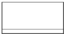
D5 ON SCREEN SET... menu
Set the data about the screen display.
FORMAT DISPLAY: Select the display mode of the signal system.
AUTO: Disappears after being displayed for a while (default).
ON: Displayed.
OFF: Not displayed.
POSITION: Select the display position for the signal system.
TOP LEFT, TOP CENTER, TOP RIGHT, BOTTOM LEFT (default), BOTTOM CENTER, BOTTOM RIGHT
CH NO: Select the display mode of the channel number
AUTO: Disappears after being displayed for a while (default).
ON: Displayed.
OFF: Not displayed.
POSITION: Select the display position for the channel number.
TOP LEFT, TOP CENTER, TOP RIGHT (default), BOTTOM LEFT, BOTTOM CENTER, BOTTOM RIGHT
CH NAME: Select the display mode of the channel name
AUTO: Disappears after being displayed for a while (default).
ON: Displayed.
OFF: Not displayed.
POSITION: Select the display position for the channel name.
TOP LEFT (default), TOP CENTER, TOP RIGHT, BOTTOM LEFT, BOTTOM CENTER, BOTTOM RIGHT
D6 PASSWORD... menu
Set the password for the menu
Enter four characters. Default setting is "9999".
CHANGE PASSWORD...: Change the password. →D61
APPLY PASSWORD...: Assign the password to a menu item. → D62
D61 CHANGE PASSWORD... menu
Change the password.
ENTER NEW PASSWORD: Enter a new password with the number button and press the ENTER button. ↔ D611
D611 CHANGE PASSWORD menu
Create a new password.
RE-ENTER PASSWORD: Enter the new password again and press the ENTER button. The password is registered.
To change it, press the MENU button.
D62 APPLY PASSWORD... menu
Select whether or not to apply the password to each menu.
PICTURE ADJ: Select YES or NO.
COLOR TEMP ADJ: Select YES or NO.
INPUT CONFIGURATION: Select YES or NO.
SYSTEM CONFIGURATION: Select YES or NO.
INDIVIDUAL ITEMS...: Display the items of the SYSTEM CONFIGURATION menu. => D621
INSTALLATION SETTINGS: Select YES or NO.
FILE MANAGEMENT: Select YES or NO.
CONTROLLER: Select YES or NO.
KEY PROTECT: Select YES or NO.
D621 APPLY PASSWORD menu
Select whether or not to apply the password to the SYSTEM CONFIGURATION menu.
NETWORK: Select YES or NO.
PARALLEL REMOTE: Select YES or NO.
POWER: Select YES or NO.
BLANKING SETTINGS: Select YES or NO.
ON SCREEN SET: Select YES or NO.
D7 MAINTENANCE... menu
The menu for the maintenance personnel is displayed.
E Installation Settings - INSTALLATION SETTINGS Menu
Overview
Initial settings of geometry, convergence, etc. are adjusted from this menu.
The following are adjusted.
- Correcting the shift of beam landing caused by the earth's magnetism (LANDING ADJUST... menu)
- Adjusting the position and size of the picture and convergence (ALIGNMENT... menu)
- Adjusting the color unevenness of the CRT (DIGITAL UNIFORMITY ADJ... menu)
Note
Perform digital uniformity adjustment after beam landing adjustment has been completed.
Structure of the INSTALLATION SETTINGS Menu
| Level 1 Level 2 Level | 3 | |
| LANDING ADJUST...E1 | NS | |
| RESTORE FACTORY DATA E11 | ||
| ALIGNMENT... E2 ROTATION | ||
| H PHASE | ||
| V CENTER | ||
| H SIZE | ||
| V SIZE | ||
| SUB CONTRAST | ||
| H PIN | ||
| H PIN BAL | ||
| H CORNER PIN | ||
| H CORNER S | ||
| H KEY | ||
| H KEY BAL | ||
| V STATIC CONV | ||
| V CONV TOP | ||
| V CONV BOT | ||
| H STATIC CONV | ||
| RESTORE FACTORY DATA | ||
| DIGITAL UNIFORMITY ADJ... E3 | MANUAL... E31 MANUAL | ADJUST E311 |
| CURSOR H SIZE | ||
| V SIZE | ||
| AUTO FULL POINTS ADJ E32 | ||
| AUTO ONE POINT ADJ E33 | ||
| SIGNAL | ||
| RESTORE FACTORY DATA | ||
Setting Lists in the INSTALLATION SETTINGS Menu
This section explains the setting lists displayed in the menu.
How to read the setting lists
- For purposes of explanation, each setting list is preceded by a menu number. These numbers are not displayed on the screen.
For more information on menu numbers, see “About menu numbers” on page 23.
- The arrow mark (⇒) refers you to another setting list that appears after you make a setting, or to an operation that is to be carried out as a result of a setting.
E INSTALLATION SETTINGS menu
LANDING ADJUST...: Set the initial value of landing, alignment, signal level adjustment, etc. ⇒ E1
ALIGNMENT...: Adjust the position and size of the picture and convergence. ⇒ E2
DIGITAL UNIFORMITY ADJ...: Adjust the color unevenness of the CRT. ⇒ E3
E1 LANDING ADJUST... menu
Set the initial value of landing, alignment, signal level adjustment, etc.
NS: Correct the beam landing shift at the top center and bottom center of the screen.
RESTORE FACTORY DATA: Reset adjustment to the default setting. ⇒ E11
E11 RESTORE FACTORY DATA menu
Reset adjustment to the default setting.
The following message appears.
RESET FACTORY DATA?
OK: Press the ENTER or End button to reset adjustment to the default setting.
CANCEL: Press the MENU button to cancel the reset operation.
E2 ALIGNMENT... menu
Adjust the position, size, or geometry of the picture or convergence with the UP and DOWN buttons or PHASE knob.
ALIGNMENT (1/3) menu
Adjust the position or size of the picture for the monitored signal system, aspect, and scan size.
ROTATION: Compensates for the screen rotation which occurs when the monitor is installed facing north or south.
The data is also applied for the monitored signal system, aspect, and scan size.

H PHASE: Adjust the horizontal picture position.

V CENTER: Adjust the vertical picture position.

H SIZE: Adjust the width of the picture.

V SIZE: Adjust the height of the picture.

SUB CONTRAST: Adjust the center value of the contrast when the image size or signal system is changed.
ALIGNMENT (2/3) menu
Adjust the geometry of the picture.
H PIN: Correct side pincushion distortion.

H PIN BAL: Correct the balance of side pincushion distortion.

H CORNER PIN: Correct pincushion distortion at the sides of the picture.

H CORNER S: Correct S pincushion distortion at the sides of the picture.

H KEY: Correct trapezoid distortion.

H KEY BAL: Correct the balance of trapezoid distortion.

ALIGNMENT (3/3) menu
Adjust the convergence.
V STATIC CONV: Adjust vertical static convergence on the whole screen.
V CONV TOP: Adjust vertical convergence at the top of the screen.
V CONV BOT: Adjust vertical convergence at the bottom of the screen.
H STATIC CONV: Adjust horizontal static convergence on the whole screen.
RESTORE FACTORY DATA: Reset the
ALIGNMENT data of the monitored signal system, aspect and scan size to the default setting. The following message appears to confirm the data reset operation.
RESTORE FACTORY DATA?
OK: Press the ENTER or Ent button to reset the data.
CANCEL: Press the MENU button to cancel the reset operation.
E3 DIGITAL UNIFORMITY ADJ... menu
Adjust the color unevenness of the CRT.
The signal system, aspect and scan size for the adjustment are displayed on the top of the screen.
MANUAL...: Adjust with the MANUAL knobs. →E31
AUTO FULL POINTS ADJ: Automatically adjust the whole area of the screen in sequence using the Sony BKM-14L Auto Setup Probe. → E32
AUTO ONE POINT ADJ: Automatically adjust only the selected adjustment point of the screen using the Sony BKM-14L Auto Setup Probe. → E33
SIGNAL: Select the white signal to be used for adjustment (default setting is EXT).
EXT: Use an external input signal. Input the appropriate signal.
INT: Use an internal white signal.
RESTORE FACTORY DATA: Reset the DIGITAL UNIFORMITY data of the monitored signal system, aspect and scan size to the default setting. The following message appears to confirm the data reset operation.
RESTORE FACTORY DATA?
OK: Press the ENTER or Ent button to reset the data.
CANCEL: Press the MENU button to cancel the reset operation.
E31 MANUAL... menu
Adjust the gain of R, G and B with the MANUAL knobs.
MANUAL ADJUST: Adjust the gain. => E311 (It may take some time to display the next menu.)
CURSOR H SIZE: Specify the horizontal size of the cursor (1 to 5).
V SIZE: Specify the vertical size of the cursor (1 to 5).

Knobs and buttons used for each adjustment
RED: CONTRAST KNOB (Adjust the R gain with the CONTRAST knob.)
GREEN: BRIGHT KNOB (Adjust the G gain with the BRIGHT knob.)
BLUE: CHROMA KNOB (Adjust the B gain with the CHROMA knob.)
CURSOR POSITION: 10KEY (Move the cursor using the numeric keypad (except the 5 button) as illustrated below. Turn the cursor ON/OFF using the 5 button.)
The cursor moves in the direction of the arrow corresponding to the pressed button.
![graph TD A["1"] --> B["2"] B --> C["3"] C --> D["4"] D --> E["5"] E --> F["6"] F --> G["7"] G --> H["8"] H --> I["9"] I --> A style A fill:#fff,stroke:#000 style B fill:#fff,stroke:#000 style C fill:#fff,stroke:#000 style D fill:#fff,stroke:#000 style E fill:#fff,stroke:#000 style F fill:#fff,stroke…](/content/2026/06/1389461/images/cdee0df126e49b3cdace5e54a00d99a9859be4c7c9fb357ac520911743b635cd.jpg)
LUMINANCE: PHASE KNOB (Adjust the phase with the PHASE knob.)
E311 MANUAL ADJUST menu
Adjust the gain at the cursor position using the CONTRAST (RED), BRIGHT (GREEN), CHROMA (BLUE) and PHASE (LUMINANCE) knobs. Move the cursor using the numeric keypad.
To reset RED/GREEN/BLUE to the value before adjustment
When you are adjusting the gain using the MANUAL adjustment knobs, you can reset the setting to the one before adjustment by pressing the corresponding MANUAL button.
To cancel adjustment
Press the MENU button. The adjusted data is cleared and the screen returns to E31. (It may take some time to change to the previous menu.)
To confirm adjustment
Press the ENTER (Ent) button.
When you want to erase characters from the screen while adjusting manually
Press the CHAR OFF button. The characters disappear. To display characters, press the CHAR OFF button again.
E32 AUTO FULL POINTS ADJ menu
Automatically adjust the whole area of the screen in sequence using the Sony BKM-14L Auto Setup Probe. Before entering the AUTO FULL POINTS ADJ menu, connect the BKM-14L to the OPTION connector. The following message appears. (It may take some time to change to the next menu.)
SET PROBE ON CURSOR
To perform adjustment, operate the BKM-14L as follows:
①Place the BKM-14L on the cursor displayed in the center of the screen. The adjustment starts. When the adjustment is completed, the cursor is displayed at the next adjustment point. ②Move the BKM-14L to the cursor. The next adjustment is performed.
In the same way, adjust each adjustment point guided by the cursor. When the adjustment of all points is completed, the screen automatically returns to the INSTALLATION SETTINGS menu.
To cancel adjustment
Press the MENU button. The adjusted data is cleared and the screen returns to the DIGITAL UNIFORMITY ADJ... menu. (It may take some time to change to the previous menu.)
If the BKM-14L is not placed on the cursor
The following message appears, and the cursor moves alternately to the right and left on the screen.
To abort, place the BKM-14L on the cursor when it is displayed on the left. Returns to the DIGITAL UNIFORMITY ADJ... menu.
To continue, place the BKM-14L on the cursor when it is displayed on the right. Returns to AUTO FULL POINTS ADJ menu.
E33 AUTO ONE POINT ADJ menu
Automatically adjust only the selected adjustment point of the screen using the Sony BKM-14L Auto Setup Probe. Before entering the AUTO ONE POINT ADJ menu, connect the BKM-14L to the OPTION connector. The cursor flashes in the center of the screen.
Knobs and buttons used for each adjustment
CURSOR POSITION: 10KEY: Move the cursor using the numeric keypad (except the 5 button). Turn the cursor ON/OFF using the 5 button.
TO CANCEL: MENU KEY: Press the MENU button to clear the adjusted data and return to the previous menu.
TO CONFIRM: ENTER KEY: Press the ENTER or Ent button to confirm the adjusted data.
To perform adjustment, operate the BKM-14L as follows:
① Move the cursor to the desired point using the numeric keypad (except the 5 button), and press the ENTER or Ent button. The following message appears and the cursor returns to the center.
SET PROBE ON CURSOR
Note
If you press the ENTER or Ent button without moving the cursor, the screen returns to the DIGITAL UNIFORMITY ADJ... menu.
② Place the BKM-14L on the cursor displayed in the center of the screen. The adjustment of the center of the screen starts. “IN PROGRESS” appears during adjustment, and the cursor returns to the point set in step ① when the adjustment is completed. ③ Move the BKM-14L to the cursor. Adjustment of the specified point is performed. “IN PROGRESS” appears during adjustment, and the cursor flashes when the adjustment of that point is completed.
To adjust another point of the screen
Move the cursor to the desired point using the numeric keypad (except the 5 button), and press the ENTER or Ent button. Then place the BKM-14L on the cursor to perform the adjustment. Repeat this procedure for each adjustment point.
To finish the adjustment
When the adjustment of the specified points is completed, press the ENTER or Ent button without operating the numeric keypad. The adjusted data is stored in the memory and the screen returns to the INSTALLATION SETTINGS menu. (It may take some time to change to the previous menu.)
Note
Operating the numeric keypad before pressing the ENTER or Ent button starts the adjustment.
To cancel adjustment
Press the MENU button. The adjusted data is cleared and the screen returns to the DIGITAL UNIFORMITY ADJ... menu. (It may take some time to change to the previous menu.)
If the BKM-14L is not placed on the cursor
The following message appears, and the cursor moves to the right and left alternately on the screen.
To abort, place the BKM-14L on the cursor when it is displayed on the left. Returns to DIGITAL UNIFORMITY ADJ... menu.
To continue, place the BKM-14L on the cursor when it is displayed on the right. Returns to AUTO ONE POINT ADJ menu.
F System Data Operation - FILE MANAGEMENT Menu
Overview
The system data is saved, copied and deleted.
The following operations are possible with this menu.
- Saving data to a "Memory Stick" (SAVE TO... menu)
- Copying data from a "Memory Stick" or other monitor (COPY FROM... menu)
- Deleting a file in a "Memory Stick" (DELETE... menu)
- Maintenance of the system data (DATA MAINTENANCE... menu)
Structure of the FILE MANAGEMENT Menu
| Level 1 Level 2 Level 3 | ||
| SAVE TO... F1 SAVE TO MEMORY STICK F11 | MEMORY STICK F111 | |
| COPY FROM...F2 | OTHER MONITOR...F21 | OTHER MONITORF211 |
| MEMORY STICK...F22 | MEMORY STICK F221 | |
| DELETE... F3 DEL ETE MEMORY STICK F31 | MEMORY STICK F311 | |
| DATA MAINTENANCE...F4 | BACK UP SYSTEM DATA F41 | |
| RE-STORE SYSTEM DATA F42 | ||
| RE-LOAD FACTORY DATA... F43 | RE-LOAD FACTORY DATA F431 | |
Setting Lists in the FILE MANAGEMENT Menu
This section explains the setting lists displayed in the menu.
How to read the setting lists
- For purposes of explanation, each setting list is preceded by a menu number. These numbers are not displayed on the screen.
For more information on the menu numbers, see "About menu numbers" on page 23.
- The arrow mark (=>) refers you to another setting list that appears after you make the setting, or to an operation that is to be carried out as a result of the setting.
F FILE MANAGEMENT menu
SAVE TO...: Save the data. => F1
COPY FROM...: Copy the data. => F2
DELETE...: Delete the file. => F3
DATA MAINTENANCE...: Service the system data.
=> F4
F1 SAVE TO... menu
Save the data in the "Memory Stick". => F11
Note
Use the "Memory Stick" after formatting.
F11 SAVE TO MEMORY STICK menu
Select the name of the file to which to write data, or create a new file name. => F111
NEW NAME: Enter a new name (1 to 20 characters).
The usable symbols are ".", "_" and "$".
The following message appears.
OVERWRITE THIS FILE?
OK: Press the ENTER or Ent button to overwrite the data.
CANCEL: Press the MENU button to cancel overwriting.
F2 COPY FROM... menu
Select the file to copy the data.
OTHER MONITOR...: Select the data of other monitor. → F21
MEMORY STICK...: Select the file of the “Memory Stick”. ↔ F22
F21 OTHER MONITOR... menu
Assign the ID No. of the source monitor.
MONITOR ID...: Enter the ID No. of the monitor.
→ [F211]
F211 OTHER MONITOR menu
Select the data to be copied.
ALL: Copy all data.
PICTURE PRESET: Copy the picture preset data.
COLOR TEMP: Copy the color temperature data.
CH MEMORY: Copy the channel memory data.
SYSTEM: Copy the system data.
F22 MEMORY STICK... menu
Select the file name in the source "Memory Stick".
F221 MEMORY STICK menu
Select the data to be read.
ALL: Copy all data.
PICTURE PRESET: Copy the picture preset data.
COLOR TEMP: Copy the color temperature data.
CH MEMORY: Copy the channel memory data.
SYSTEM: Copy the system data.
F3 DELET... menu
Delete the file in the "Memory Stick". ⇒ F31
F31 DELETE MEMORY STICK menu
Delete the file in the "Memory Stick".
Select the file F311
F311 MEMORY STICK menu
The following confirmation message appears.
DELETE THIS FILE?
OK: Press the ENTER or Ent button to delete data.
CANCEL: Press the MENU button to cancel the delete operation.
F4 DATA MAINTENANCE... menu
The password is confirmed to display the DATA MAINTENANCE... menu.
BACK UP SYSTEM DATA...: Write the data to the "Memory Stick". ⇒ F41
RE-STORE SYSTEM DATA...: Read the data from the "Memory Stick". ⇔ F42
RE-LOAD FACTORY DATA...: Read the factory default data of the installed board. ⇒ F43
The "IN PROGRESS -" is displayed during data writing.
(It may take some time to write the data.)
F42 RE-STORE SYSTEM DATA menu
The following message appears to confirm the data restore operation.
ALL DATA WILL BE RESTORED AND MONITOR WILL RESTART ARE YOU SURE?
OK: To continue, press the ENTER or Ent button. Read the data from the monitor "Memory Stick" and automatically restart the monitor.
CANCEL: To cancel, press the MENU button. Return to the DATA MAINTENANCE... menu.
F43 RE-LOAD FACTORY DATA menu
Select a slot where a board is installed to reload factory default data to the board.
Select SLOT2 to SLOT6. SLOT5 is divided into VIDEO data and BLANKING data. ⇒ F431
F431 RE-LOAD FACTORY DATA menu
The following message appears to confirm the data reload operation.
DATA RESET TO ITS FACTORY SETTING AND MONITOR WILL RESTART ARE YOU SURE?
OK: To continue, press the ENTER or Ent button. Resets the data and automatically restart the monitor.
CANCEL: To cancel, press the MENU button. Returns to the RE-LOAD FACTORY DATA menu.
G Displaying Information On the Monitor – STATUS Menu
Overview
This menu is used to view general data about the monitor status, current channel, etc.
The following information is displayed on the two pages of the STATUS menu.
- Data about the current channel and the input adaptor installed in the slots in the rear panel (STATUS (1/2) menu)
- Data about the monitor and the controller (controlled monitor) in use (STATUS (2/2) menu)
Structure of the STATUS Menu
| Level 1 Level 2 | |
| CH STATUS... G1 CH | |
| OP | |
| IN | |
| FORMAT | |
| NAME | |
| SLOT STATUS G2 MODEL NAME | |
| SERIAL NO | |
| MODEL NAME | |
| SERIAL NO | |
| SOFTWARE VERSION | |
| OPERATION TIME | |
| CRT TURN ON TIME | |
| IP ADDR | |
| CONTROLLER STATUS... G3 M | MODEL NAME |
| SERIAL NO | |
| SOFTWARE VERSION | |
| IP ADDR |
Setting Lists in the STATUS Menu
This section explains the setting lists displayed in the menu.
How to read the setting lists
- For purposes of explanation, each setting list is preceded by a menu number. These numbers are not displayed on the screen.
For more information on the menu numbers, see “About menu numbers” on page 23.
- The arrow mark (=>) refers you to another setting list that appears after you make the setting, or to an operation that is to be carried out as a result of the setting.
G STATUS menu
Select the STATUS (1/2) menu or STATUS (2/2) menu.
STATUS (1/2) menu
CH STATUS...: Display the information of the used channel. => G1
SLOT STATUS...: Display the type of OPTION 1 to 3. => G2
HD-SDI/D1...: Display when BKM-61D is installed.
SDI/COMPOSITE...: Display when BKM-62HS is installed.
COMPONENT...: Display when BKM-68X is installed.
EMPTY...: Display when no adaptor is installed.
STATUS (2/2) menu
Data on the monitor and controller (controlled monitor) is displayed.
MODEL NAME: Model name of the monitor
SERIAL NO: Serial number of the monitor
SOFTWARE VERSION: Software version of the monitor
OPERATION TIME: Operation time (in hours) of the monitor
CRT TURN ON TIME: Used time of the CRT (in hours)
IP ADDR: IP address of the monitor
CONTROLLER STATUS...: Information on the controller (controlled monitor) => G3
G1 CH STATUS... menu
Display the information on the used channel.
The information of the assigned internal signal is displayed on the channels 80 to 89 and 91 to 97.
CH: Channel number
OP: Option slot number (OPTION1 to 3)
IN: Input connector number
FORMAT: Input signal format
NAME: Channel name
The information of the internal signal is displayed in channels 80 to 89 and 91 to 97.
G2 SLOT STATUS menu
Display the type of input adaptor installed in OPTION1 to 3.
MODEL NAME: Model name
SERIAL NO: Serial number
G3 CONTROLLER STATUS... menu
Display information on the controller (controlled monitor).
MODEL NAME: Model name
SERIAL NO: Serial number
SOFTWARE VERSION: Software version
IP ADDR: IP address
H Setting the Controller - CONTROLLER Menu
Overview
When the Monitor Control Unit BKM-15R is connected, this menu is for the network setting of the controller.
Note
When the BVM-A14F5U/A14F5M/A14F5A is used as the controller, the NETWORK SETTINGS... menu and the NETWORK SW menu cannot be selected.
- Setting the display method of the monitor select display window (MONITOR ID DISPLAY menu)
- Settings for IP address, subnet mask and default gateway of the controller (NETWORK SETTINGS... menu)
- Displaying the setting of the NETWORK switch (NETWORK SW menu)
Structure of the CONTROLLER Menu
| Level 1 Level 2 Level 3 | ||
| MONITOR ID DISPLAY H1 | ||
| NETWORK SETTINGS... H2 | IP ADDRESS | |
| SUBNET MASK | ||
| DEFAULT GATEWAY | ||
| ADDRESS | ||
| NETWORK SW | ||
| SNMP SETTINGS... H3 | CONTACT | |
| NAME | ||
| LOCATION | ||
| TRAP | ||
Setting Lists in the CONTROLLER Menu
This section explains the setting lists displayed in the menu.
How to read the setting lists
- For purposes of explanation, each setting list is preceded by a menu number. These numbers are not displayed on the screen.
For more information on the menu number, see “About menu numbers” on page 23.
- The arrow mark (⇒) refers you to another setting list that appears after you make the setting, or to an operation that is to be carried out as a result of the setting.
H CONTROLLER menu
The network, system, etc. of the controller is set.
MONITOR ID DISPLAY: When the NETWORK switch is set to LAN, set the display method of the monitor select display window. => [H1]
NETWORK SETTINGS...: Display the NETWORK SETTINGS menu. => H2
NETWORK SW: Display the setting of the NETWORK switch (LAN or PEER TO PEER). As the NETWORK switch is not equipped with BVM-A14F5U/A14F5M/A14F5A and the function is set to LAN mode, when BVM-A14F5U/A14F5M/A14F5A is used as the controller, this is not displayed.
SNMP SETTINGS...: Set CONTACT, NAME, LOCATION and TRAP. <=> H3
H1 MONITOR ID DISPLAY menu
When the NETWORK switch is set to LAN, the display method of the monitor select display window is set. As the NETWORK switch is not equipped with BVM-A14F5U/A14F5M/A14F5A and the function is set to LAN mode, when BVM-A14F5U/A14F5M/A14F5A is used as the controller, this is always selectable.
ON: Always displayed (default).
AUTO: Displayed during operating by the remote connection and cleared after operation
OFF: Not displayed.
H2 NETWORK SETTINGS... menu
Set the IP address, subnet mask and default gateway.
IP ADDRESS: Set the IP address (default setting is "192.168.000.100").
SUBNET MASK: Set the subnet mask (default setting is “255.255.255.0”).
DEFAULT GATEWAY: Set the default gateway on or off (default setting is OFF).
ADDRESS: Set the default gateway (default setting is “----.----.(no setting)”).
CANCEL: Select to cancel the setting.
CONFIRM: Select to save the setting.
Note
When the NETWORK switch of the BKM-15R is set to PEER TO PEER, the IP address is set to
"192.168.000.100" regardless of the display.
When the NETWORK switch is set to LAN, the IP address is set to the displayed one.
H3 SNMP SETTINGS... menu
CONTACT menu: Set the information of the administrator.
NEW NAME: Enter a new name (up to 20 characters).
The usable symbols are “(”, “)”, “.”, “-”, “+”, “/”, “%”, “*”, “#”, “_”, “\$” and “(space)” (12 symbols).
NAME menu: Set the information for the administration (device ID).
NEW NAME: Enter a new name (up to 20 characters).
The usable symbols are “(”, “)”, “.”, “-”, “+”, “/”, “%”, “*”, “#”, “_”, “\$” and “(space)” (12 symbols).
LOCATION menu: Set the location information.
NEW NAME: Enter a new name (up to 20 characters).
The usable symbols are “(”, “)”, “.”, “-”, “+”, “/”, “%”, “*”, “#”, “_”, “$” and “(space)” (12 symbols).
TRAP menu: Set the address to send the information. TRAP1 and TRAP2 are set.
TRAP1: Set the IP address (default setting is "000.000.000.000").
TRAP2: Set the IP address (default setting is "000.000.000.000").
CANCEL: Select to cancel the changed or confirmed setting.
CONFIRM: Select to save the changed or confirmed setting.
Setting Key Protect - KEY PROTECT Menu
Overview
The data is locked so that they cannot be changed by an unauthorized user.
Setting Lists in the KEY PROTECT Menu
This section explains the setting lists displayed in the menu.
How to read the setting lists
- For purposes of explanation, each setting list is preceded by a menu number. These numbers are not displayed on the screen.
For more information on the menu number, see “About menu numbers” on page 23.
The arrow mark ( ⇒ ) refers you to another setting list that appears after you make the setting, or to an operation that is to be carried out as a result of the setting.
KEY PROTECT menu
ON: The button on the monitor (except the menu operation buttons and monitor select buttons) does not function and other settings are not changeable.
OFF: Release the lock.
Appendixes
Specifications
General
System 15.625 kHz - 45 kHz (For details, see "Available Signal Systems" on page 55.)
CRT
HR Trinitron, 4:3 aspect ratio
Aperture grille pitch:
0.25 mm, 90 degree deflection, ∅29.4 mm diameter in-line gun
Effective picture size
With 16:9 aspect ratio:
267.5 × 150.5 mm (10 5/8 × 6 inches) (w/h)
306.9 mm (12 1/8 inches) (diagonal size)
With 4:3 aspect ratio:
267.5 × 200.6 mm (10 5/8 × 8 inches) (w/h)
331.6 mm (13 1/8 inches) (diagonal size)
CRT protection: EHT (extremely high tension) protection type
Warm-up time:
approx. 30 minutes
Anode voltage:
25 kV with no beam current
Nominal chromaticity coordinates:
SMPTE C phosphor (BVM-A14F5U)
| x | y | |
| R | 0.630 0.340 | |
| G | 0.310 0.595 | |
| B | 0.155 0.070 | |
Error: ± 0.007 or less
EBU phosphor (BVM-A14F5M/A14F5A)
| x | y | |
| R | 0.640 0 | 330 |
| G | 0.290 0 | 600 |
| B | 0.150 0 | 060 |
Error: ± 0.007 or less
Power consumption
170 W (When an optional adaptor is installed)
Power requirements
100 to 240 V AC, 1.8 to 0.8 A, 50/60 Hz
Peak inrush current
①Power ON, current probe method: 47 A (240 V)
②Hot switching inrush current, measured in accordance with European standard EN55103-1 22 A (230 V)
Mass approx. 27 kg (59 lb 8 oz)
Input/output connectors
Control
OPTION: Mini-DIN 8-pin (female) × 1
PARALLEL REMOTE: D-sub 9-pin (female) × 1
SERVICE: D-sub 9-pin (male) × 1
LAN (10BASE-T/100BASE-TX): RJ-45 × 1
Video signal
Differential gain
Less than 5% (for luminance from 0 to 100 cd/m²)
Differential phase
Less than 5° (for luminance from 0 to 100 cd/m²)
Frequency response
48 Hz to 30 MHz, +1 dB/ -3 dB
DC restoration Back porch type
Black level fluctuation: less than 1% for 10% to 90% APL input signal variation
Synchronization
Vertical blanking time
Less than 650 μs.
Horizontal blanking time
Less than 3.77 μs. (1080/60I, 1035/60I)
Picture performance
Normal scan 5% over scan of CRT effective screen area (±10% of CRT effective screen area)
Under scan: 3% under scan of CRT effective screen area (± 10% of CRT effective screen area)
Linearity: Within a central area bounded by a circle with a diameter equal to the picture height, less than 0.5% of the picture height, and outside the same area, about 1% of the picture height
Color temperature
D61, D65, D93 (adjustable to other color temperatures)
Convergence error
Within a central area bounded by a circle with a diameter equal to the picture height: less than 0.4 mm with a central area bounded by a circle and less than 0.7 mm at any other point.
Standard luminescence
100 cd/m² (at standard 1 Vp-p, 100% white signal)
Raster size stability
Less than 1% of picture height (at 100 cd/m² peak luminescence, 10 to 90% APL)
Resolution: 600 TV lines (16:9)
800 TV lines (4:3) (at screen center, 100 cd/m² luminescence)
Operating conditions
Temperature: 0°C to 35°C (32°F to 95°F)
Optimum temperature
20°C to 30°C (68°F to 86°F)
Humidity 0% to 90% (no condensation)
Pressure 700 hPa to 1060 hPa
Storage and transport conditions
Temperature -10°C to 40°C (14°F to 104°F)
Humidity 0% to 90%
Pressure 700 hPa to 1060 hPa
Accessories supplied
AC power cord (1)
AC plug holder (1)
Fuse (1)
Tally plate (1)
4:3 mask (1)
Operation manual (1)
Menu tree reference (1)
Cleaning of the CRT Surface (1)
Design and specifications are subject to change without notice.
Available Signal Systems
| System Total | lines per frame | Active lines per frame | Frame rate (Hz) | Scanning format | Aspect ratio | Standard Display on the monitor*3 |
| 575/50I 62 | 5 575 25 2:1 | interlace 16:9/4:3 | Rec ITU-R BT.60 | 1 575/50I | ||
| 480/59.94I 5 | 25 483 30/1.0 | 01 2:1 | interlace 16:9/4:3 Rec | ITU-R BT.601 | 480/60I | |
| 576/50P | 625 | 576 | 50 | Progressive | 16:9/4:3 | Rec ITU-R BT.1358 |
| 480/59.94P | 525 483 | 60/1.001 Progressive | 16:9/4:3 | SMPTE 293M/ Rec ITU-R BT.1358 | ||
| 1080/24PsF | 1125 | 1080 | 24 | 2:1 interlace | 16:9 | SMPTE RP211 |
| 24/1.001 | ||||||
| 1080/50I *1 | 1125 | 1080 | 25 | 2:1 interlace | 16:9 | SMPTE 274M |
| 1035/60I | 1125 | 1035 | 30 | 2:1 interlace | 16:9 | SMPTE 240M/ SMPTE 260M/ BTA S-001B |
| 30/1.001 | ||||||
| 1080/60I *2 | 1125 | 1080 | 30 | 2:1 interlace | 16:9 | SMPTE 274M 1080/60I |
| 30/1.001 | ||||||
| 720/50P | 750 | 720 | 50 | Progressive | 16:9 | SMPTE 296M |
| 720/60P | 750 720 | 60 | Progressive | 16:9 | SMPTE 296M | |
| 60/1.001 |
*1 Also applicable to 1080/25PsF.
*2 Also applicable to 1080/30PsF.
*3 When no signal is input or the input signal is not available, NO SYNC is displayed on the monitor.
Available Signal Formats
| Signal format | System | BKM-61D | BKM-62HS | BKM-68X | Standard | ||
| Analog Composite | |||||||
| NTSC | Setup level | 0 | 480/59.94I O | × | × | SMPTE 170M | |
| 7.5 | |||||||
| PAL575/50I O | × | × | Rec.ITU-R BT.470 | ||||
| PAL-M 480/59.94I O | × | × | Rec.ITU-R BT.470 | ||||
| SECAM 575/50I O | × | × | Rec.ITU-R BT.470 | ||||
| Analog (Y/C) | |||||||
| NTSC | Setup level | 0 | 480/59.94I O | × | × | ||
| 7.5 | |||||||
| PAL575/50I O | × | × | |||||
| PAL-M 480/59.94I O | × | × | |||||
| SECAM 575/50I O | × | × | |||||
| Analog Component | |||||||
| 1035/60I* | × | × | OSMPTE 240M/BTA S-001B | ||||
| 1080/60I* | × | × | ○ | SMPTE 274M | |||
| 1080/50I | × | × | ○ | ||||
| 1080/30PsF* | × | × | ○ | SMPTE RP 211 | |||
| 1080/25PsF | × | × | ○ | ||||
| 1080/24PsF* | × | × | ○ | ||||
| 720/60P* | × | × | ○ | SMPTE 296M | |||
| 720/50P | × | × | ○ | ||||
| 480/59.94P | × | × | ○ | SMPTE 293M/Rec.ITU-R BT.1358 | |||
| 576/50P | × | × | ORec.ITU-R BT.1358 | ||||
| Component level | N10/SMPTE | 480/59.94I | × | × | ○ | ||
| 575/50I | × | × | OEBU N10 | ||||
| Beta | 0 | 480/59.94I | × | × | ○ | ||
| 7.5 | |||||||
| Analog RGB | |||||||
| 1035/60I* | × | × | OSMPTE 240M/BTA S-001B | ||||
| 1080/60I* | × | × | ○ | SMPTE 274M | |||
| 1080/50I | × | × | ○ | ||||
| 1080/30PsF* | × | × | ○ | SMPTE RP 211 | |||
| 1080/25PsF | × | × | ○ | ||||
| 1080/24PsF* | × | × | ○ | ||||
| 720/60P* | × | × | ○ | SMPTE 296 M | |||
| 720/50P | × | × | ○ | ||||
| 480/59.94P | × | × | ○ | SMPTE 293M/Rec.ITU-R BT.1358 | |||
| 576/50P | × | × | ORec.ITU-R BT.1358 | ||||
| 480/59.94I | × | × | ORec.ITU-R BT.601 | ||||
| 575/50I | × | × | ORec.ITU-R BT.601 | ||||

| Signal format | System | BKM-61D | BKM-62HS | BKM-68X | Standard | ||
| D1 | |||||||
| 480/59.94I O | O | × | SMPTE 259M | ||||
| 575/50I O | O | × | |||||
| D2 | |||||||
| NTSC | Setup level | 0 | 480/59.94I O | × | × | SMPTE 259M7.5 | |
| PAL 575/50I O | × | × | |||||
| HD SDI (10 bit system only) | |||||||
| Single Link 4:2:2 YPBPR | 1035/60I* | × | O | × | SMPTE 292M | ||
| Single Link 4:2:2 YPBPR | 1080/60I* | × | O | × | SMPTE 292M | ||
| Dual Link 4:4:4 | YPBPR | SMPTE 372M | |||||
| GBR | |||||||
| Single Link 4:2:2 YPBPR | 1080/50I | × | O | × | SMPTE 292M | ||
| Dual Link 4:4:4 | YPBPR | SMPTE 372M | |||||
| GBR | |||||||
| Single Link 4:2:2 YPBPR | 1080/30PsF* | × | O | × | SMPTE 292M | ||
| Dual Link 4:4:4 | YPBPR | SMPTE 372M | |||||
| GBR | |||||||
| Single Link 4:2:2 YPBPR | 1080/25PsF | × | O | × | SMPTE 292M | ||
| Dual Link 4:4:4 | YPBPR | SMPTE 372M | |||||
| GBR | |||||||
| Single Link 4:2:2 YPBPR | 1080/24PsF* | × | O | × | SMPTE 292M | ||
| Dual Link 4:4:4 | YPBPR | SMPTE 372M | |||||
| GBR | |||||||
| Single Link 4:2:2 YPBPR | 720/60P* | × | O | × | SMPTE 292M | ||
| Single Link 4:2:2 YPBPR | 720/50P | × | O | × | SMPTE 292M | ||
* Also compatible with 1/1.001.

Dimensional Drawing
Unit: mm (inches)
Top
Front

Right Side

Left Side
Rear
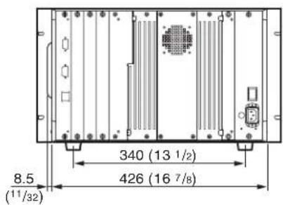
Connection Cable Specifications for Color Temperature Probes
Special cables are required to connect color temperature probes other than the Sony BKM-14L to the monitor.
The following diagrams show specifications and pin assignments for the required cables.
Connection cable for UDT INSTRUMENTS SLS 9400-FC probe

Connection cable for KONICA MINOLTA CA-100 probe


Connection cable for KONICA MINOLTA CA-100plus probe
D-sub 9-pin connector (male)

Mini DIN 8-pin connector (male)

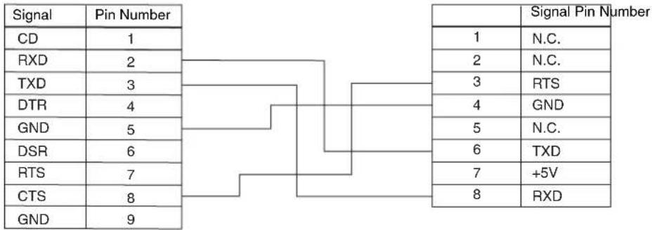
Connection cable for DK-TECHNOLOGIES PM 5639 probe (corresponds to DK-TECHNOLOGIES PM 5639/00 cable)
Modular connector

Mini DIN 8-pin connector (male)

![graph TD A["Signal Pin Number"] --> B["+5V"] A --> C["N.C."] A --> D["RXD"] A --> E["TXD"] A --> F["N.C."] A --> G["GND"] H["Pin Number"] --> I["1"] H --> J["2"] H --> K["3"] H --> L["4"] H --> M["5"] H --> N["6"] H --> O["7"] H --> P["8"] Q["Signal"] --> R["N.C."] Q --> S["N.C."] Q --> T["RTS"] Q -…](/content/2026/06/1389461/images/d18f5e47aa7825b936aa4fb4fcfa6ed352f120a25e6997749d0d4ad9d1e7bc76.jpg)
Connection cable for THOMA TF6 probe
D-sub 15-pin connector (male)

Mini DIN 8-pin connector (male)


The menu index shows the menu items provided with this monitor in alphabetical order. For your reference, each menu item is followed by the page of this manual on which
the item is explained, its menu number, and the main menu that the item belongs to.
| Menu Item | Page | Menu number | Main menu | |
| A | ALIGNMENT | 4 | 4 | E2INSTALLATION SETTINGS menu |
| ANALYZE 33B5COLOR TEMP ADJ menu | ||||
| APPLY PASSWORD 42D62SYSTEM CONFIGURATION menu | ||||
| AUTO 29A1PICTURE ADJ menu | ||||
| 32B2COLOR TEMP ADJ menu | ||||
| AUTO ADJUST | 29 | A11 | PICTURE ADJ menu | |
| 33B21 | COLOR TEMP ADJ menu | |||
| AUTO FULL POINTS ADJ | 46 | E32 | INSTALLATION SETTINGS menu | |
| AUTO ONE POINT ADJ | 46 | E33 | INSTALLATION SETTINGS menu | |
| B | BACK UP SYSTEM DATA | 48 | F41 | FILE MANAGEMENT menu |
| BLANKING SETTINGS | 42 | D4 | SYSTEM CONFIGURATION menu | |
| C | CH STATUS | 50 | G1 | STATUS menu |
| CHANGE PASSWORD | 42 | D61 | SYSTEM CONFIGURATION menu | |
| CHANNEL NAME | 38 | C4 | INPUT CONFIGURATION menu | |
| COLOR TEMP ADJ | 30 | B | COLOR TEMP ADJ menu | |
| COMPONENT | 37 | C15 | INPUT CONFIGURATION menu | |
| COMPOSITE | 36 | C13 | INPUT CONFIGURATION menu | |
| CONTROLLER | 51 | H | CONTROLLER menu | |
| CONTROLLER STATUS | 50 | G3 | STATUS menu | |
| COPY FROM | 30 | A3 | PICTURE ADJ menu | |
| 33B3 | COLOR TEMP ADJ menu | |||
| 39 | C5 | INPUT CONFIGURATION menu | ||
| 48F2 | FILE MANAGEMENT menu | |||
| D | DATA MAINTENANCE | 48 | F4 | FILE MANAGEMENT menu |
| DELETE | 48 | F3 | FILE MANAGEMENT menu | |
| DELETE MEMORY STICK | 48 | F31 | FILE MANAGEMENT menu | |
| DIGITAL UNIFORMITY ADJ | 45 | E3 | INSTALLATION SETTINGS menu | |
| DK-TECHNOLOGIES | 30 | B | COLOR TEMP ADJ menu | |
| DUAL LINK HD-SDI | 36 | C12 | INPUT CONFIGURATION menu | |
| F | FILE MANAGEMENT | 47 | F | FILE MANAGEMENT menu |
| FORMAT | 36 | C1 | INPUT CONFIGURATION menu | |
| I | INPUT CONFIGURATION | 34 | C | INPUT CONFIGURATION menu |
| INSTALLATION SETTINGS | 43 | E | INSTALLATION SETTINGS menu | |
| K | KEY PROTECT | 52 | I | KEY PROTECT menu |
| KONICA MINOLTA | 30 | B | COLOR TEMP ADJ menu | |
| L | LANDING ADJUST | 44 | E1 | INSTALLATION SETTINGS menu |


| Menu Item | Page | Menu number | Main menu | |
| M MAINTENANCE 42 D7 | SYSTEM | CONFIGURATION | menu | |
| MANUAL 31 B1 COLOR TEMP ADJ menu | ||||
| 45 E31 | INSTALLATION | SETTINGS | menu | |
| MANUAL ADJUST 29 A2 PICTURE ADJ menu | ||||
| 32 B11 COLOR TEMP ADJ menu | ||||
| 46 E311 | INSTALLATION | SETTINGS | menu | |
| MATRIX 37 C2 INPUT CONFIGURATION menu | ||||
| MEMORY STICK | 30 | A33 | PICTURE ADJ menu | |
| 33 B33 | COLOR TEMP ADJ menu | |||
| 39 | C53 | INPUT CONFIGURATION menu | ||
| 48 | F111 | FILE MANAGEMENT menu | ||
| 48 | F22 | FILE MANAGEMENT menu | ||
| 48 | F311 | FILE MANAGEMENT menu | ||
| MODE | 37 | C3 | INPUT CONFIGURATION menu | |
| MONITOR ID | 33 | B321 | COLOR TEMP ADJ menu | |
| MONITOR ID DISPLAY | 51 | H1 | CONTROLLER menu | |
| N NETWORK | 40 | D1 | SYSTEM CONFIGURATION menu | |
| NETWORK SETTINGS | 41 | D11 | SYSTEM CONFIGURATION menu | |
| 51 H2 | CONTROLLER menu | |||
| O ON SCREEN SET | 42 | D5 | SYSTEM CONFIGURATION menu | |
| OTHER CH | 39 | C51 | INPUT CONFIGURATION menu | |
| OTHER MONITOR | 30 | A32 | PICTURE ADJ menu | |
| 33 B32 | COLOR TEMP ADJ menu | |||
| 39 C52 | INPUT CONFIGURATION menu | |||
| 48 | F21 | FILE MANAGEMENT menu | ||
| 48 | F211 | FILE MANAGEMENT menu | ||
| P PARALLEL REMOTE | 41 | D2 | SYSTEM CONFIGURATION menu | |
| PASSWORD | 42 | D6 | SYSTEM CONFIGURATION menu | |
| PICTURE ADJ | 28 | A | PICTURE ADJ menu | |
| POWER | 41 | D3 | SYSTEM CONFIGURATION menu | |
| PRESET VALUE | 30 | A31 | PICTURE ADJ menu | |
| 33 B31 COLOR TEMP ADJ menu | ||||
| R RE-LOAD FACTORY DATA | 49 | F43 | FILE MANAGEMENT menu | |
| RESTORE FACTORY DATA | 33 | B4 | COLOR TEMP ADJ menu | |
| 44 E11 INSTALLATION SETTINGS menu | ||||
| RE-STORE SYSTEM DATA | 49 | F42 | FILE MANAGEMENT menu | |
| S SAVE TO 48 F1 FILE MANAGEMENT menu | ||||
| SAVE TO MEMORY STICK 48 F11 FILE MANAGEMENT menu | ||||
| SDI/HD-SDI 36 C11 INPUT CONFIGURATION menu | ||||
| SLOT STATUS 50 G2 STATUS menu | ||||
| SNMP SETTINGS 41 D12 SYSTEM CONFIGURATION menu | ||||
| 51 H3 | CONTROLLER menu | |||
| STATUS | 49 | G | STATUS menu | |
| SYSTEM CONFIGURATION | 39 | D | SYSTEM CONFIGURATION menu | |
| T | THOMA | 30 | B | COLOR TEMP ADJ menu |
| U | UDT INSTRUMENTS | 30 | B | COLOR TEMP ADJ menu |
| Y | YC | 37 | C14 | INPUT CONFIGURATION menu |
| 1 | 1 PIN... - 8 PIN... | 41 | D21 | SYSTEM CONFIGURATION menu |

The material contained in this manual consists of information that is the property of Sony Corporation and is intended solely for use by the purchasers of the equipment described in this manual.
Sony Corporation expressly prohibits the duplication of any portion of this manual or the use thereof for any purpose other than the operation or maintenance of the equipment described in this manual without the express written permission of Sony Corporation.
For Customer in China
Printed on recycled paper.
Printed in Japan
2007.12
© 2005


- FOR SAFETY
- NOTE
- TO RETURN TO THE 16:9 MASK
- WARNING
- FOR THE CUSTOMERS IN USA (BVM-A14F5U)
- FOR THE CUSTOMERS IN CANADA (BVM-A14F5U)
- FOR THE CUSTOMERS IN EUROPE (BVM-A14F5M/BVM-A14F5A)
- CHAPTER 2 MENU
- APPENDIXES
- OVERVIEW
- CHAPTER
- PRECAUTIONS
- ON SAFETY
- ON INSTALLATION
- ON CLEANING
- ON REPACKING
- ON RACK MOUNTING
- ON MAGNETISM
- ON THE CRT
- ON DISPLAYING THE 4:3 SIGNAL
- FEATURES
- MULTIFORMAT
- HIGH RESOLUTION PICTURE TUBE
- REMOTE CONTROL FUNCTION IN THE NETWORK CONNECTION (ETHERNET CONTROL)
- AUTO CHROMA/PHASE/MATRIX AND WHITE BALANCE FUNCTIONS
- SAFE AREA DISPLAY
- EXPANDABLE INPUT CAPABILITY
- STABLE COLOR TEMPERATURE
- BLUE-ONLY MODE CONVENIENT FOR MONITORING NOISE
- MATRIX SELECTION
- DIGITAL UNIFORMITY CIRCUIT
- OTHER FEATURES
- OPTIONS
- FOR EXTERNAL CONTROL
- BKM-15R MONITOR CONTROL UNIT
- BKM-14L AUTO SETUP PROBE
- INPUT ADAPTORS
- BKM-61D SDI/ANALOG MULTI INPUT ADAPTOR
- BKM-62HS HD SDI/SDI INPUT ADAPTOR
- BKM-68X ANALOG COMPONENT INPUT ADAPTOR
- CONNECTOR PANEL CONFIGURATION
- INSTALLING A DECODER ADAPTOR
- NOTES
- LOCATION AND FUNCTION OF PARTS
- ① TALLY LAMP
- ② DEGAUSS BUTTON
- ③ L/ SWITCH
- ④ NUMERIC KEYPAD
- CHANNEL NUMBER ENTRY METHOD
- ⑤ MONITOR SELECT BUTTONS
- ⑥ MANUAL ADJUSTMENT BUTTONS AND KNOBS
- ⑦ MENU OPERATION BUTTONS
- ⑧ OPERATE LAMP
- STANDBY LAMP
- ⑩ OVER LOAD LAMP
- ⑪ MONITOR SELECT LAMPS AND WINDOW
- ⑫ FUNCTION BUTTONS
- ⑬"MEMORY STICK" INSERTION SLOT
- OPTION CONNECTOR
- REAR PANEL
- ①MAIN POWER SWITCH
- ② AC IN SOCKET (3-PIN)
- ③ FUSE
- ④ INPUT OPTION SLOTS
- ⑤ PARALLEL REMOTE CONNECTOR (FEMALE, D-SUB 9-PIN)
- ⑥ SERVICE TERMINAL (MALE, D-SUB 9-PIN)
- CAUTION
- INSERTING/EJECTING THE "MEMORY STICK
- TO INSERT THE "MEMORY STICK
- TO EJECT THE "MEMORY STICK
- NOTES ON "MEMORY STICK
- WHAT IS "MEMORY STICK
- TYPES OF "MEMORY STICK
- MEMORY STICK
- MEMORY STICK (MAGICGATE/HIGH-SPEED TRANSFER COMPATIBLE)
- MAGICGATE MEMORY STICK
- MEMORY STICK-ROM
- MEMORY STICK” (WITH MEMORY SELECT FUNCTION)
- MEMORY STICK PRO
- AVAILABLE TYPES OF "MEMORY STICK
- NOTE ON DATA READ/WRITE SPEED
- WHAT IS MAGICGATE
- INSTALLATION OF THE 4:3 MASK
- INSTALLING THE 4:3 MASK
- REPLACING THE 16:9 MASK
- CONNECTIONS
- SELECTING THE MONITOR/GROUP
- ABOUT MONITOR ID NO. AND GROUP ID NO
- ABOUT MONITOR SELECT BUTTONS AND LAMPS
- REMOTE CONNECTION
- SELECTING THE DEFAULT SETTINGS
- BVM-A14F5M ONLY
- TURN ON THE POWER
- SELECT THE AREA WHERE YOU INTEND TO USE THE UNIT BY USING THE MENU OPERATION BUTTONS (SEE PAGE 22)
- MENU
- BASIC MENU OPERATIONS
- DISPLAYING THE MENU
- ABOUT MENU NUMBERS
- MENU OPERATION
- TO ABORT MENU OPERATION
- IF "NG" OR "ERROR" APPEARS DURING MENU OPERATION
- CHOOSING ONE OF TWO OR MORE SELECTIONS
- SELECTING IN SETTING MODE
- SELECTING FROM THE SETTING LIST
- ENTERING A NUMERICAL VALUE
- ENTERING CHARACTERS
- TO CORRECT THE ENTERED CHARACTER
- MENU STRUCTURE
- A PICTURE ADJUSTMENT – PICTURE ADJ MENU
- SETTING LISTS IN THE PICTURE ADJ MENU
- HOW TO READ THE SETTING LISTS
- A PICTURE ADJ MENU
- PRESET VALUE
- WHEN THE MATRIX DATA IS CHANGED
- CHANGE INPUT CONFIG
- MATRIX VALUE (1080/720)
- RESET FACTORY DATA
- TO CANCEL ADJUSTMENT
- WHEN YOU WANT TO ERASE CHARACTERS FROM THE SCREEN WHILE ADJUSTING MANUALLY
- TO RESET THE SETTING TO THE DEFAULT
- TO CONFIRM ADJUSTMENT
- B ADJUSTING THE COLOR TEMPERATURE – COLOR TEMP ADJ MENU
- BEFORE ADJUSTING THE COLOR TEMPERATURE
- STRUCTURE OF THE COLOR TEMP ADJ MENU
- SETTING LISTS IN THE COLOR TEMP ADJ MENU
- B COLOR TEMP ADJ MENU
- WHEN THE COLOR TEMPERATURE DATA IS CHANGED
- COLOR TEMP PRESET
- B1 MANUAL... MENU
- B11 MANUAL ADJUST MENU
- KNOBS FOR EACH ADJUSTMENT
- TO RESET RED/GREEN/BLUE TO THE VALUE BEFORE ADJUSTMENT
- USING THE COL TEMP (SHORT-CUT) BUTTON
- B2 AUTO... MENU
- SET PROBE ON CURSOR
- TO CANCEL/STOP THE ADJUSTMENT
- RESTORE FACTORY DATA
- TO CANCEL THE ANALYSIS
- C SETTING THE INPUT CONFIGURATION – INPUT CONFIGURATION MENU
- CHANNELS 80 TO 89 ASSIGNMENT
- CHANNELS 91 TO 97 ASSIGNMENT
- ASSIGNING SLOT AND CONNECTOR NUMBERS
- SETTING LISTS IN THE INPUT CONFIGURATION MENU
- © INPUT CONFIGURATION MENU
- INPUT CONFIGURATION (1/2) MENU
- INPUT CONFIGURATION (2/2) MENU
- MARKER MODE (2/3) MENU
- MARKER MODE (3/3) MENU
- C4 CHANNEL NAME... MENU
- D SYSTEM CONFIGURATION - SYSTEM CONFIGURATION MENU
- STRUCTURE OF THE SYSTEM CONFIGURATION MENU
- SETTING LISTS IN THE SYSTEM CONFIGURATION MENU
- D1 NETWORK... MENU
- D4 BLANKING SETTINGS... MENU
- D5 ON SCREEN SET... MENU
- D6 PASSWORD... MENU
- D61 CHANGE PASSWORD... MENU
- D611 CHANGE PASSWORD MENU
- D62 APPLY PASSWORD... MENU
- D621 APPLY PASSWORD MENU
- D7 MAINTENANCE... MENU
- E INSTALLATION SETTINGS - INSTALLATION SETTINGS MENU
- SETTING LISTS IN THE INSTALLATION SETTINGS MENU
- E INSTALLATION SETTINGS MENU
- E1 LANDING ADJUST... MENU
- E11 RESTORE FACTORY DATA MENU
- E2 ALIGNMENT... MENU
- ALIGNMENT (1/3) MENU
- ALIGNMENT (2/3) MENU
- ALIGNMENT (3/3) MENU
- RESTORE FACTORY DATA: RESET THE
- E3 DIGITAL UNIFORMITY ADJ... MENU
- E31 MANUAL... MENU
- KNOBS AND BUTTONS USED FOR EACH ADJUSTMENT
- E311 MANUAL ADJUST MENU
- E32 AUTO FULL POINTS ADJ MENU
- IF THE BKM-14L IS NOT PLACED ON THE CURSOR
- E33 AUTO ONE POINT ADJ MENU
- TO ADJUST ANOTHER POINT OF THE SCREEN
- TO FINISH THE ADJUSTMENT
- F SYSTEM DATA OPERATION - FILE MANAGEMENT MENU
- STRUCTURE OF THE FILE MANAGEMENT MENU
- SETTING LISTS IN THE FILE MANAGEMENT MENU
- F42 RE-STORE SYSTEM DATA MENU
- ALL DATA WILL BE RESTORED AND MONITOR WILL RESTART ARE YOU SURE
- F43 RE-LOAD FACTORY DATA MENU
- F431 RE-LOAD FACTORY DATA MENU
- DATA RESET TO ITS FACTORY SETTING AND MONITOR WILL RESTART ARE YOU SURE
- G DISPLAYING INFORMATION ON THE MONITOR – STATUS MENU
- SETTING LISTS IN THE STATUS MENU
- G STATUS MENU
- STATUS (1/2) MENU
- STATUS (2/2) MENU
- G1 CH STATUS... MENU
- G2 SLOT STATUS MENU
- G3 CONTROLLER STATUS... MENU
- H SETTING THE CONTROLLER - CONTROLLER MENU
- STRUCTURE OF THE CONTROLLER MENU
- SETTING LISTS IN THE CONTROLLER MENU
- H CONTROLLER MENU
- H1 MONITOR ID DISPLAY MENU
- H2 NETWORK SETTINGS... MENU
- H3 SNMP SETTINGS... MENU
- SETTING KEY PROTECT - KEY PROTECT MENU
- SETTING LISTS IN THE KEY PROTECT MENU
- KEY PROTECT MENU
- SPECIFICATIONS
- GENERAL
- INPUT/OUTPUT CONNECTORS
- VIDEO SIGNAL
- SYNCHRONIZATION
- PICTURE PERFORMANCE
- OPERATING CONDITIONS
- STORAGE AND TRANSPORT CONDITIONS
- ACCESSORIES SUPPLIED
- DIMENSIONAL DRAWING
- CONNECTION CABLE SPECIFICATIONS FOR COLOR TEMPERATURE PROBES
- CONNECTION CABLE FOR UDT INSTRUMENTS SLS 9400-FC PROBE
- CONNECTION CABLE FOR KONICA MINOLTA CA-100 PROBE
- CONNECTION CABLE FOR KONICA MINOLTA CA-100PLUS PROBE
- CONNECTION CABLE FOR DK-TECHNOLOGIES PM 5639 PROBE (CORRESPONDS TO DK-TECHNOLOGIES PM 5639/00 CABLE)
- CONNECTION CABLE FOR THOMA TF6 PROBE
Brand : SONY
Model : BVM-A14F5M
Category : Monitor