
H61M-P20/W8 - Motherboard MSI - Free user manual and instructions
Find the device manual for free H61M-P20/W8 MSI in PDF.

| Product Type | Motherboard |
| Brand | MSI |
| Model | H61M-P20/W8 |
| Form Factor | Micro-ATX |
| CPU Socket | LGA1155 |
| Chipset | Intel H61 Express |
| Memory Type | DDR3 |
| Number of Memory Slots | 2 (max 16 GB) |
| Supported Memory Frequency | DDR3 1066/1333 MHz |
| Power Connector | ATX 24-pin + ATX12V 4-pin |
| Dimensions | 22.6 cm x 17.0 cm |
| Weight | 0.45 kg |
| Main Features | Supports Intel Core i3/i5/i7 LGA1155 CPUs, integrated graphics via D-Sub and DVI-D, 4 SATA 3 Gb/s ports, 1 PCIe 2.0 x16 slot, 2 PCIe 2.0 x1 slots, Realtek ALC887 6-channel audio, Realtek 8111E Gigabit Ethernet |
| Care and Cleaning | Regular dusting with compressed air, avoid moisture |
| Safety | Overvoltage protection, USB port protection circuits |
| Spare Parts and Repairability | Solid capacitors, removable BIOS, standard parts compatibility |
| General Information | RoHS compliant, Windows 8 compatible, 3-year warranty |
Frequently Asked Questions - H61M-P20/W8 MSI
User questions about H61M-P20/W8 MSI
0 question about this device. Answer the ones you know or ask your own.
Ask a new question about this device
Download the instructions for your Motherboard in PDF format for free! Find your manual H61M-P20/W8 - MSI and take your electronic device back in hand. On this page are published all the documents necessary for the use of your device. H61M-P20/W8 by MSI.
USER MANUAL H61M-P20/W8 MSI
H61M-P31 (G3) series
MS-7788 (v1.x) Mainboard
G52-77881X1
COPYRIGHT NOTICE
The material in this document is the intellectual property of MICRO-STAR INTERNATIONAL. We take every care in the preparation of this document, but no guarantee is given as to the correctness of its contents. Our products are under continual improvement and we reserve the right to make changes without notice.
TRADEMARKS
All trademarks in this manual are properties of their respective owners.
MSI is registered trademark of Micro-Star Int'l Co., Ltd.
NVIDIA® is registered trademark of NVIDIA Corporation.
ATI is registered trademark of ATI Technologies, Inc.
AMD is registered trademarks of AMD Corporation.
Intel is registered trademarks of Intel Corporation.
Windows® is registered trademarks of Microsoft Corporation.
AMI is registered trademark of American Megatrends, Inc.
Award® is a registered trademark of Phoenix Technologies Ltd.
Sound Blaster® is registered trademark of Creative Technology Ltd.
Realtek® is registered trademark of Realtek Semiconductor Corporation.
■ JMicron® is registered trademark of JMicron Technology Corporation.
Netware® is a registered trademark of Novell, Inc.
Lucid® is trademarks of LucidLogix Technologies, Ltd.
VIA is registered trademark of VIA Technologies, Inc.
■ ASMedia® is registered trademark of ASMedia Technology Inc.
iPad, iPhone, and iPod are trademarks of Apple Inc.
REVISION HISTORY
| Revision | Revision History | Date |
| V1.0 | First release for PCB 1.X | 2011/12 |
SAFETY INSTRUCTIONS
Always read the safety instructions carefully.
- Keep this User Manual for future reference.
- Keep this equipment away from humidity.
Lay this equipment on a reliable flat surface before setting it up.
- The openings on the enclosure are for air convection hence protects the equipment from overheating. Do not cover the openings.
- Make sure the voltage of the power source is at 110/220V before connecting.
- Place the power cord such a way that people can not step on it. Do not place anything over the power cord.
Always Unplug the Power Cord before inserting any add-on card or module.
All cautions and warnings on the equipment should be noted.
- Never pour any liquid into the opening that can cause damage or cause electrical shock.
If any of the following situations arises, get the equipment checked by service personnel:
The power cord or plug is damaged.
Liquid has penetrated into the equipment.
The equipment has been exposed to moisture.
The equipment does not work well or you can not get it work according to User Manual.
The equipment has been dropped and damaged.
The equipment has obvious sign of breakage.
DO NOT LEAVE THIS EQUIPMENT IN AN ENVIRONMENT UNCONDITIONED, STORAGE TEMPERATURE ABOVE 60^ (140^) , IT MAY DAMAGE THE EQUIPMENT.
TECHNICAL SUPPORT
If a problem arises with your system and no solution can be obtained from the user's manual, please contact your place of purchase or local distributor. Alternatively, please try the following help resources for further guidance.
■ Visit the MSI website for technical guide, BIOS updates, driver updates, and other information: http://www.msi.com/service/download
- Contact our technical staff at: http://support.msi.com
FCC-B RADIO FREQUENCY INTERFERENCE STATEMENT
This equipment has been tested and found to comply with the limits for a class B digital device, pursuant to part 15 of the FCC rules.

These limits are designed to provide reasonable protection against harmful interference in a residential installation. This equipment generates, uses and can radiate radio frequency energy and, if not installed and used in accordance with the instruction manual, may cause harmful interference to radio communications. However, there is no guarantee that interference will occur in a particular installation. If this equipment does cause harmful interference to radio or television reception, which can be determined by turning the equipment off and on, the user is encouraged to try to correct the interference by one or more of the measures listed below.
Reorient or relocate the receiving antenna.
Increase the separation between the equipment and receiver.
Connect the equipment into an outlet on a circuit different from that to which the receiver is connected.
Consult the dealer or an experienced radio/ television technician for help.
Notice 1
The changes or modifications not expressly approved by the party responsible for compliance could void the user's authority to operate the equipment.
Notice 2
Shielded interface cables and A.C. power cord, if any, must be used in order to comply with the emission limits.
VOIR LA NOTICE D'INSTALLATION AVANT DE RACCORDER AU RESEAU.

Micro-Star International
MS-7788
This device complies with Part 15 of the FCC Rules. Operation is subject to the following two conditions:
(1) this device may not cause harmful interference, and
(2) this device must accept any interference received, including interference that may cause undesired operation.
BATTERY INFORMATION
European Union:

Batteries, battery packs, and accumulators should not be disposed of as unsorted household waste. Please use the public collection system to return, recycle, or treat them in compliance with the local regulations.
Taiwan:

廢電池請回收
For better environmental protection, waste batteries should be collected separately for recycling or special disposal.
California, USA:
The button cell battery may contain perchlorate material and requires special handling when recycled or disposed of in California. For further information please visit: http://www.dtdsc.ca.gov/hazardouswaste/perchlorate/
CAUTION
Danger of explosion if battery is incorrectly replaced.
Replace only with the same or equivalent type recommended by the manufacturer.
CHEMICAL SUBSTANCES INFORMATION
In compliance with chemical substances regulations, such as the EU REACH Regulation (Regulation EC No. 1907/2006 of the European Parliament and the Council), MSI provides the information of chemical substances in products at:
http://www.msi.com/html/popup/csr/evmptrtt_pcm.html
BSMI_EMI聲明
警告使用者
To protect the global environment and as an environmentalist, MSI must remind you that...
Under the European Union ("EU") Directive on Waste Electrical and Electronic Equipment, Directive 2002/96/EC, which takes effect on August 13, 2005, products of "electrical and electronic equipment"

cannot be discarded as municipal wastes anymore, and manufacturers of covered electronic equipment will be obligated to take back such products at the end of their useful life. MSI will comply with the product take back requirements at the end of life of MSI-branded products that are sold into the EU. You can return these products to local collection points.
DEUTSCH
Thank you for choosing the H61M-P20 (G3)/ H61M-P31 (G3) series (MS-7788 v1.x) Micro-ATX mainboard. These series are designed based on Intel® H61 chipset for optimal system efficiency. Designed to fit the advanced Intel® LGA1155 processor, these series deliver a high performance and professional desktop platform solution.
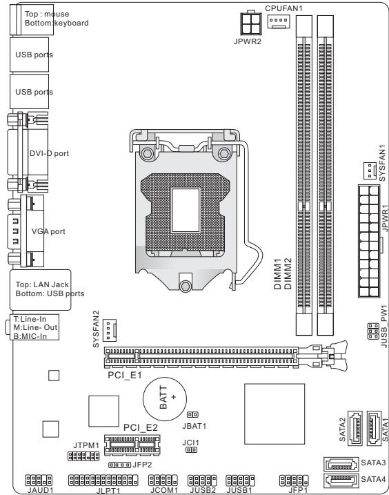
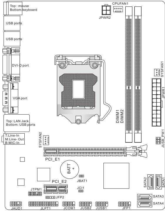
Layout
SPECIFICATIONS
Processor Support
Support 3rd generation Intel® Core™ i7/ Core™ i5/ Core™ i3/ Pentium®/ Celeron® processors for LGA1155 socket (For the latest information about CPU, please visit http://www.msi.com/service/cpu-support)
Chipset
Intel® H61 chipset
Memory Support
2 DDR3 DIMMs support DDR3 1333/ 1066 SDRAM (total Max. 16GB)
Supports Dual-Channel mode (For more information on compatible components, please visit http://www.msi.com/service/test-report)
LAN
Supports LAN 10/ 100 by Realtek® 8105E (H61M-P20 (G3))
Supports LAN 10/ 100/ 1000 by Realtek® 8111E (H61M-P31 (G3))
Audio
Chip integrated by Realtek® ALC887
Supports 8-channels audio out
Compliant with Azalia 1.0 Spec
SATA
4 SATA 3Gb/s ports by Intel® H61
Connectors
Back panel
- 1 PS/2 mouse port
- 1 PS/2 keyboard port
- 1 DVI-D port*
- 1 VGA port*
- 6 USB 2.0 ports
- 1 LAN jack
- 3 flexible audio jacks**
^ (The DVI-D & VGA ports only work with Integrated Graphics Processor.)
*(To reach the 8-channel sound effect, the 7th and 8th channels must be outputted from front panel.)
On-Board Connectors
- 2 USB 2.0 connectors
- 1 Front Panel Audio connector
- 1 Parallel Port connector (optional)
- 1 Serial Port connector (optional)
- 1 TPM connector (optional)
- 1 Chassis Intrusion connector
Slots
1 PCIe 3.0 x16 slot
1 PCIe 2.0 x1 slot
Form Factor
Micro-ATX (22.6 cm X 17.3 cm)
Mounting
6 mounting holes
If you need to purchase accessories and request the part numbers, you could search the product web page and find details on our web address below http://www.msi.com/index.php
SCREW HOLES
When you install the mainboard, you have to place the mainboard into the chassis in the correct direction. The locations of screws holes on the mainboard are shown as below.
The side has to toward the rear, the position for the I/O shield of the chassis.
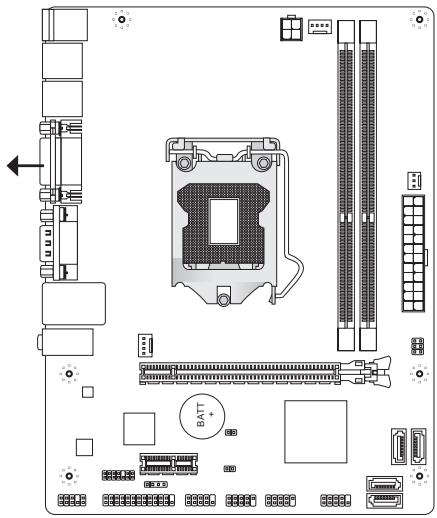


Screw holes
Refer above picture to install standoffs in the appropriate locations on chassis and then screw through the mainboard screw holes into the standoffs.
IMPORTANT
- To prevent damage to the mainboard, any contact between the mainboard circuit and chassis or unnecessary standoffs mounted on the chassis is prohibited.
- Please make sure there is no metal components placed on the mainboard or within the chassis that may cause short circuit of the mainboard.
REAR PANEL
The rear panel provides the following connectors:
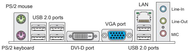
IMPORTANT
- To reach the 8-channel sound effect, the 7th and 8th channels must be output from front panel.
- The DVI-D & VGA ports only work with Integrated Graphics Processor.
HARDWARE SETUP
This section provides instructions on CPU and memory installation, as well as jumper settings on the mainboard. While doing the installation, be careful in holding the components and follow the installation procedures.
CPU & Cooler Installation Procedures for LGA1155
When you are installing the CPU, make sure that you install the cooler to prevent overheating. If you do not have the CPU cooler, consult your dealer before turning on the computer.
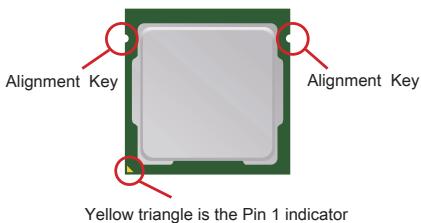
Introduction to LGA 1155 CPU
The surface of LGA 1155 CPU. Remember to apply some thermal paste on it for better heat dispersion.
Follow the steps below to install the CPU & cooler correctly. Wrong installation will cause the damage of your CPU & mainboard.
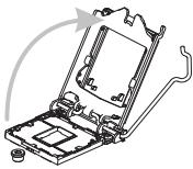
- Open the load lever.
- Lift the load lever up to fully open position.
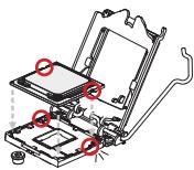
- After confirming the CPU direction for correct mating, put down the CPU in the socket housing frame. Be sure to grasp on the edge of the CPU base. Note that the alignment keys are matched.
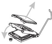
- Remove the plastic cap. Engage the load lever while pressing down lightly onto the load plate.
- Secure the lever near the hook end under the retention tab.
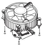
- Make sure the four hooks are in proper position before you install the cooler. Align the holes on the mainboard with the cooler. Push down the cooler until its four clips get wedged into the holes of the mainboard.
- Press the four hooks down to fasten the cooler. Turn over the mainboard to confirm that the clip- ends are correctly inserted.
- Finally, attach the CPU Fan cable to the CPU fan connector on the mainboard.
IMPORTANT
- Visually inspect if the CPU is seated well into the socket. If not, take out the CPU with pure vertical motion and reinstall.
- Read the CPU status in BIOS.
- Whenever CPU is not installed, always protect your CPU socket pin with the plastic cap covered to avoid damaging.
- Please refer to the documentation in the CPU fan package for more details about the CPU fan installation.
Installing Memory Modules
- The memory module has only one notch on the center and will only fit in the right orientation.
- Insert the memory module vertically into the DIMM slot. Then push it in until the golden finger on the memory module is deeply inserted in the DIMM slot. You can barely see the golden finger if the memory module is properly inserted in the DIMM slot.
- The plastic clip at each side of the DIMM slot will automatically close.
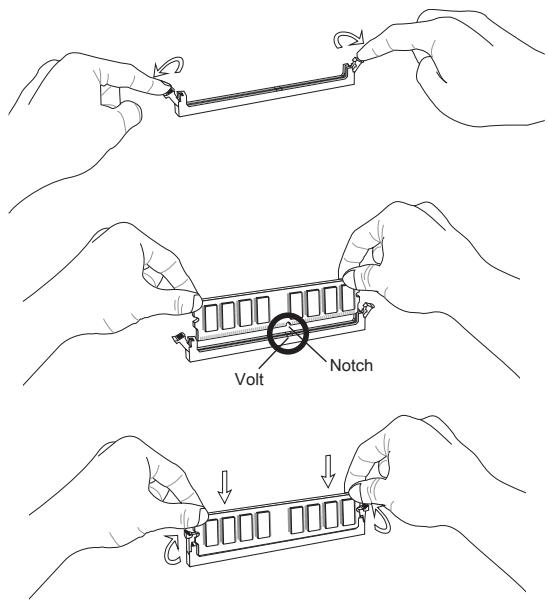
IMPORTANT
- In Dual-Channel mode, make sure that you install memory modules of the same type and density in different channel DIMM slots.
- To enable successful system boot-up, always insert the memory modules into the DIMM1 first.
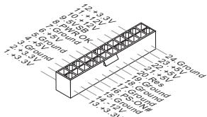
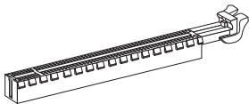
ATX 24-Pin Power Connector: JPWR1
This connector allows you to connect an ATX 24-pin power supply. To connect the ATX 24-pin power supply, make sure the plug of the power supply is inserted in the proper orientation and the pins are aligned. Then push down the power supply firmly into the connector.
ATX 4-Pin Power Connector: JPWR2
This 12V power connector is used to provide power to the CPU.
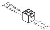
IMPORTANT
Make sure that all the connectors are connected to proper ATX power supplies to ensure stable operation of the mainboard.
Serial ATA Connector: SATA1~4
This connector is a high-speed Serial ATA interface port. Each connector can connect to one Serial ATA device.

IMPORTANT
Please do not fold the Serial ATA cable into a 90-degree angle. Otherwise, data loss may occur during transmission.
Fan Power Connectors: CPUFAN1, SYSFAN1, SYSFAN2
The fan power connectors support system cooling fan with +12V . When connecting the wire to the connectors, always note that the red wire is the positive and should be connected to the +12V ; the black wire is Ground and should be connected to GND. If the mainboard has a System Hardware Monitor chipset onboard, you must use a specially designed fan with speed sensor to take advantage of the CPU fan control.
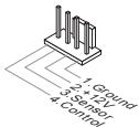
CPUFAN1/ SYSFAN2
SYSFAN1
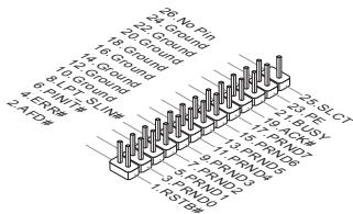
Parallel Port Connector: JLPT1 (optional)
This connector is used to connect an optional parallel port bracket. The parallel port is a standard printer port that supports Enhanced Parallel Port (EPP) and Extended Capabilities Parallel Port (ECP) mode.
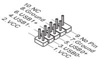
Front USB Connector: JUSB1/ JUSB2
This connector, compliant with Intel® I/O Connectivity Design Guide, is ideal for connecting high-speed USB interface peripherals such as USB HDD, digital cameras, MP3 players, printers, modems and the like.
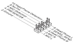
Front Panel Audio Connector: JAUD1
This connector allows you to connect the front panel audio and is compliant with Intel® Front Panel I/O Connectivity Design Guide.
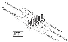
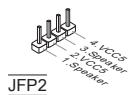
Front Panel Connectors: JFP1, JFP2
These connectors are for electrical connection to the front panel switches and LEDs. The JFP1 is compliant with Intel® Front Panel I/O Connectivity Design Guide.
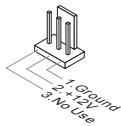
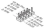
Serial Port Connector: JCOM1 (optional)
This connector is a 16550A high speed communication port that sends/receives 16 bytes FIFOs. You can attach a serial device.
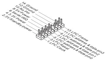
TPM Module Connector: JTPM1 (optional)
This connector connects to a TPM (Trusted Platform Module) module. Please refer to the TPM security platform manual for more details and usages.
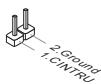
Chassis Intrusion Connector: JCI1
This connector connects to the chassis intrusion switch cable. If the chassis is opened, the chassis intrusion mechanism will be activated. The system will record this status and show a warning message on the screen. To clear the warning, you must enter the BIOS utility and clear the record.
Clear CMOS Jumper: JBAT1
There is a CMOS RAM on board with an external battery power supply to preserve the system configuration data. With the CMOS RAM, the system can automatically boot OS every time it is turned on. If you want to clear the system configuration, please temporarily short these two pins to clear data by using a metal object.

Keep Data

Clear Data
IMPORTANT
You can clear CMOS by touching two pins once with a metal object while the system is off. Avoid clearing the CMOS while the system is on; it will damage the mainboard.
USB power Jumper:JUSB_PWM1
This jumper allows you to enable/ disable the "Wakeup from S3/S4/S5 by USB and PS/2 device" function.
JUSB_PWM1


Disabled

Enabled
IMPORTANT
If you set the jumper to Enabled, the power supply must be able to provide +5VSB and at least 2A currents.
PCI Express Slot
The PCIe slot supports the PCIe interface expansion card.
The PCIe x16 slot

The PCIe x1 slot
BIOS SETUP
Power on the computer and the system will start POST (Power On Self Test) process. When the message below appears on the screen, press key to enter Setup.
Press DEL to enter Setup Menu
If the message disappears before you respond and you still wish to enter Setup, restart the system by turning it OFF and On or pressing the RESET button. You may also restart the system by simultaneously pressing <Ctrl> , <Alt> , and <Delete> keys.
IMPORTANT
The items under each BIOS category described in this chapter are under continuous update for better system performance. Therefore, the description may be slightly different from the latest BIOS and should be held for reference only.
The Menu Bar
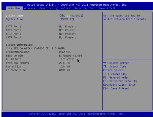
Main Menu
Use this menu for basic system configurations, such as time, date etc.
Advanced
Use this menu to set up the items of special enhanced features.
Overclocking
Use this menu to specify the settings for DRAM timing and CPU features.
M-Flash
Use this menu to read/ flash the BIOS form storage drive (FAT/ FAT32 format only).
Security
Use this menu to set supervisor and user passwords.
Boot
Use this menu to specify the priority of boot devices.
Save & Exit
This menu allows you to load the BIOS default values or factory default settings into the BIOS and exit the BIOS setup utility with or without changes.
Overclocking

Current CPU / DRAM Frequency
These items show the current clocks of CPU and Memory speed. Read-only.
Adjust CPU Ratio
This item controls the multiplier that is used to determine the internal clock speed of the processor relative to the external or motherboard clock speed. It is available only when the processor supports this function.
Adjusted CPU Frequency
It shows the adjusted CPU frequency. Read-only.
Internal PLL Overvoltage
This item are used to adjust the PLL voltage.
EIST
The Enhanced Intel SpeedStep technology allows you to set the performance level of the microprocessor whether the computer is running on battery or AC power. This field will appear after you installed the CPU which supports speedstep technology.
Intel Turbo Boost
This item will appear when you install a CPU with Intel Turbo Boost technology. This item is used to enable/ disable Intel Turbo Boost technology. It can scale processor frequency higher dynamically when applications demand more performance and TDP headroom exists. It also can deliver seamless power scalability (Dynamically scale up, Speed-Step Down).
OC Genie Button Operation
This field is used to enable/ disable OC Genie function.
DRAM Frequency
This is used to adjust the memory frequency.
Adjusted DRAM Frequency
It shows the adjusted DRAM frequency. Read-only.
DRAM Timing Mode
Select whether DRAM timing is controlled by the SPD (Serial Presence Detect) EEPROM on the DRAM module. Setting to [Auto] enables DRAM timings and the following "Advanced DRAM Configuration" sub-menu to be determined by BIOS based on the configurations on the SPD. Selecting [Manual] allows users to configure the DRAM timings and the following related "Advanced DRAM Configuration" sub-menu manually.
Advanced DRAM Configuration
Press
Command Rate
This setting controls the DRAM command rate.
tCL
This controls the CAS latency, which determines the timing delay (in clock cycles) before SDRAM starts a read command after receiving it.
tRCD
When DRAM is refreshed, both rows and columns are addressed separately. This setup item allows you to determine the timing of the transition from RAS (row address strobe) to CAS (column address strobe). The less the clock cycles, the faster the DRAM performance.
tRP
This setting controls the number of cycles for Row Address Strobe (RAS) to be allowed to precharge. If insufficient time is allowed for the RAS to accumulate its charge before DRAM refresh, refreshing may be incomplete and DRAM may fail to retain data. This item applies only when synchronous DRAM is installed in the system.
tRAS
This setting determines the time RAS takes to read from and write to memory cell.
tRFC
This setting determines the time RFC takes to read from and write to a memory cell.
tWR
Minimum time interval between end of write data burst and the start of a precharge command. Allows sense amplifiers to restore data to cells.
tWTR
Minimum time interval between the end of write data burst and the start of a column-read command. It allows I/O gating to overdrive sense amplifiers before read command starts.
tRRD
Specifies the active-to-active delay of different banks.
tRTP
Time interval between a read and a precharge command.
tFAW
This item is used to set the tFAW (four activate window delay) timing.
IWCL
This item is used to set the tWCL (Write CAS Latency) timing.
Advanced Channel 1/2 Timing Configuration
Press
GT OverClocking
This item allows you to enable/ disable the overclocking of integrated graphics.
GT Ratio
This setting controls the ratio of integrated graphics frequency to enable the integrated graphics to run at different frequency combinations.
Adjusted GT Frequency
It shows the adjusted integrated graphics frequency. Read-only.
Spread Spectrum
When the mainboard's clock generator pulses, the extreme values (spikes) of the pulses create EMI (Electromagnetic Interference). The Spread Spectrum function reduces the EMI generated by modulating the pulses so that the spikes of the pulses are reduced to flatter curves.
IMPORTANT
-
If you do not have any EMI problem, leave the setting at [Disabled] for optimal system stability and performance. But if you are plagued by EMI, select the value of Spread Spectrum for EMI reduction.
-
The greater the Spread Spectrum value is, the greater the EMI is reduced, and the system will become less stable. For the most suitable Spread Spectrum value, please consult your local EMI regulation.
- Remember to disable Spread Spectrum if you are overclocking because even a slight jitter can introduce a temporary boost in clock speed which may just cause your overclocked processor to lock up.
DRAM Voltage
This item is used to adjust the memory voltage.
CPU Features
Press
Hyper-Threading
The processor uses Hyper-Threading technology to increase transaction rates and reduces end-user response times. The technology treats the two cores inside the processor as two logical processors that can execute instructions simultaneously. In this way, the system performance is highly improved. If you disable the function, the processor will use only one core to execute the instructions. Please disable this item if your operating system doesn't support HT Function, or unreliability and instability may occur.
Active Processor Cores
This item allows you to select the number of active processor cores.
Limit CPUID Maximum
It is designed to limit the listed speed of the processor to older operating systems.
Execute Disable Bit
Can prevent certain classes of malicious "buffer overflow" attacks where worms can try to execute code to damage your system. It is recommended you keep this enabled always.
Intel Virtualization Tech
Enhances virtualization and allows the system to act as multiple virtual systems. See Intel's official website for more information.
Intel VT-D Tech
This item is used to enable/disable the Intel VT-D technology. For further information please refer to Intel's official website.
Power Technology
This item allows you to select the Intel Dynamic Power technology mode.
C1E Support
Enable system to reduce CPU power consumption while idle. Not all processors support Enhanced Halt state (C1E).
OverSpeed Protection
Monitors current CPU draw as well as power consumption; if it exceeds a certain level, the processor automatically reduces its clock speed. For overclocking, it is recommended this feature is disabled.
Intel C-State
C-state is a power management state that detects when the system is idle and lowers power consumption accordingly.
Package C State limit
This field allows you to select a C-state mode.
Long duration power limit (W)
This field allows you to adjust the TDP power limit for the long duration.
Long duration maintained (s)
This field allows you to adjust the maintaining time for long duration power limit.
Short duration power limit (W)
This field allows you to adjust the TDP power limit for the short duration.
Primary/ Secondary plane turbo power limit (W)
These fields allow you to adjust the TDP limit for the primary/ secondary plane turbo.
Save & Exit
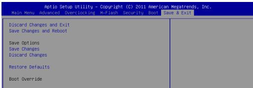
Discard Changes and Exit
Use this item to abandon all changes and exit setup.
Save Changes and Reset
Use this item to save changes and reset the system.
Save Changes
Use this item to save changes.
Discard Changes
Use this item to abandon all changes.
Restore Defaults
Use this item to load the optimized default values set by the BIOS vendor.
= = Boot Override = =
The installed storage devices will appear on this menu, you can select one of them be a boot device.
中国
#
H61M-P20 (G3)/ H61M-P31 (G3) SIRIUS (MS-7788 v1.x) Micro-ATX [enlbu] 5000000000000000000000000000000000000000000000000000000000000000000000000000000000000000
ReiA
#
J
LGA1155 3e/teh 3e/teh Intel® Core™ i7/ Core™ i5/ Core™ i3/ Pentium® Celeron® Pro/Pro series 责件通知。CPUe 大大大大大大大大大大大大大大大大大大大大大大大大大大大大大大大大大大大大大大大大大大大大
#
Intel H61
J
(8) 堂當人送來三者,如和他達意而入,日暮而朝,日暮而朝,日暮而朝,日暮而朝,日暮而朝,日暮而朝,日暮而朝,日暮而朝,日暮而朝,日暮而朝,日暮而朝,日暮而朝,日暮而朝,日暮而朝,日暮而朝,日暮而朝,日暮而朝,日暮而朝,日暮而朝,日暮而朝,日暮而
Current CPU / DRAM Frequency
Adjusted CPU Frequency
調整たCPU周波数表示し。
Internal PLL Overvoltage
PLL電圧を調整しら。
EIST
OC Genie Button Operation
Adjusted DRAM Frequency
Advanced Channel 1/2 Timing Configuration
Adjusted GT Frequency
Active Processor Cores
Intel Virtualization Tech
OverSpeed Protection
Package C State limit
Long duration power limit (W)
Long duration maintained (s)
Short duration power limit (W)
Primary/ Secondary plane turbo power limit (W)
Discard Changes and Exit
变更設定值を保存せら最終了ま�。