
ICP-X7000 - Video Conferencing System SONY - Free user manual and instructions
Find the device manual for free ICP-X7000 SONY in PDF.


| Product Type | Video Conferencing System |
| Brand | Sony |
| Model | ICP-X7000 |
| Dimensions (W x H x D) | 300 x 200 x 50 mm |
| Weight | 2.0 kg |
| Power Supply | 100-240 V AC, 50/60 Hz |
| Power Consumption | 30 W (max) |
| Video Resolution | 1080p Full HD |
| Audio Codec | G.711, G.722, AAC-LC |
| Network Interface | Ethernet (10/100/1000 Mbps), Wi-Fi 802.11 a/b/g/n/ac |
| Connectivity | HDMI out, USB 2.0/3.0, Audio line in/out, RJ45 |
| Main Functions | HD video conferencing, screen sharing, whiteboard, recording |
| Maintenance | Clean with dry cloth; avoid liquids; update firmware regularly |
| Safety | Do not block vents; use only supplied power adapter; avoid extreme temperatures |
| Spare Parts | Remote control, power adapter, HDMI cable, mounting kit |
| Repairability | Contact Sony authorized service center for repairs; user-replaceable remote batteries |
| General Information | Supports up to 20 participants; compatible with major conferencing platforms |
Frequently Asked Questions - ICP-X7000 SONY
User questions about ICP-X7000 SONY
0 question about this device. Answer the ones you know or ask your own.
Ask a new question about this device
Download the instructions for your Video Conferencing System in PDF format for free! Find your manual ICP-X7000 - SONY and take your electronic device back in hand. On this page are published all the documents necessary for the use of your device. ICP-X7000 by SONY.
USER MANUAL ICP-X7000 SONY
ICP-X1116 ICP-X1124 ICP-X1216 ICP-X1224
User's Guide English
Software Version 2.31 and Later
1st Edition (Revised 4)
NOTICE TO USERS
© 2023, 2024, 2025 Sony Corporation. All rights reserved. This manual or the software described herein, in whole or in part, may not be reproduced, translated or reduced to any machine readable form without prior written approval from Sony Corporation.
SONY CORPORATION PROVIDES NO WARRANTY WITH REGARD TO THIS MANUAL, THE SOFTWARE OR OTHER INFORMATION CONTAINED HEREIN AND HEREBY EXPRESSLY DISCLAIMS ANY IMPLIED WARRANTIES OF MERCHANTABILITY OR FITNESS FOR ANY PARTICULAR PURPOSE WITH REGARD TO THIS MANUAL, THE SOFTWARE OR SUCH OTHER INFORMATION. IN NO EVENT SHALL SONY CORPORATION BE LIABLE FOR ANY INCIDENTAL, CONSEQUENTIAL OR SPECIAL DAMAGES, WHETHER BASED ON TORT, CONTRACT, OR OTHERWISE, ARISING OUT OF OR IN CONNECTION WITH THIS MANUAL, THE SOFTWARE OR OTHER INFORMATION CONTAINED HEREIN OR THE USE THEREOF.
Sony Corporation reserves the right to make any modification to this manual or the information contained herein at any time without notice. The software described herein may also be governed by the terms of a separate user license agreement.
Functions Supported in Version 2.31
The functions newly supported in MLS-X1 System Ver. 2.31 are as follows.
Macros
Added GPI output status symbol and parameter to macro events (see page 571)
Table of Contents
Functions Supported in Version 2.31......3
Chapter 1 Overview
Introduction ......17
Notation in this Manual....17
System Configuration....18
Boxes and Islands....18
MLS Manager 18
Logical Switchers....18
Physical Box IDs....18
Logical Box IDs 19
About Inaccessible Boxes ......19
Chapter 2 Names and Functions of Parts
Control Panel....20
Control Panel Configuration (ICP-X7000) 21
Cross-Point Control Block 23
Transition Control Block....27
Transition Control Block (Simple Type) ....29
Independent Key Transition Control Block....31
Flexi Pad Control Block....32
Key Control Block ....33
Key Fader Control Block ......36
Device Control Block....37
Numeric Keypad Control Block......41
Utility/Shotbox Control Block ......43
AUX Bus Control Block 45
Control Panel Configuration (ICP-X1000 Series) 49
Cross-Point Control Block 50
Transition Control Block....53
Flexi Pad Control Block....55
Device Control Block....56
Utility Control Block....61
Power Supply and Connectors...... 63
MLS-X1 Live Production Processor ......63
ICP-X7000 Control Panel 69
ICP-X1000 Series Control Panel....70
Menu....71
Screen Structure 71
Pop-up Window....73
Chapter 3 Menu Operation
Overview 74
Menu Operating Environment....74
Installing a Root Certificate ....74
Signing In / Signing Out 75
Displaying the User's Guide 76
Displaying License Information...... 77
Shutting Down / Rebooting 77
Shutting Down the System....77
Rebooting the System....77
Basic Menu Operation ....78
Menu Selection....78
Setting Menu Items 79
Selecting and Setting List Items......80
Setting Parameters....81
Initializing Settings (Default Recall)......85
Switching Taskbars 85
Registering Menus as Favorites...... 86
Linking a Control Panel with the Menu ... 87
Entering and Displaying Text/Numbers....87
Selecting and Displaying Regions 89
Types of Regions......89
Selecting a Region....89
Chapter 4 Selecting Signals
Overview 91
Selecting a Bus (Cross-Point Control Block) 95
Operation Mode of a Button Row .....95
Bus Types and Assignments .....95
Selecting a Bus (AUX Bus Control Block) 97
Operation Mode of a Button Row .....97
Bus Types and Assignments .....98
Selecting Signals 99
Assigning Signals....99
Cross-Point Button Numbers .....99
Cross-Point Button Display....100
Cross-Point Hold ....101
Selecting a Key Fill Signal/Key Source Signal ....101
Selecting a Video Signal/Key Signal .....102
Preventing Operation of Cross-point Buttons....103
Preventing Operation of Cross-Point Buttons (Inhibit Function)....103
Preventing Operation of a Cross-Point Button Row (Protect Function)....103
Chapter 5 Transitions
Overview ....104
Basic Operation for Transitions ..... 105
Next Transitions ....106
Selecting a Next Transition .....106
Key Priority ......107
Setting Key Priority....108
Transition Type 109
Setting a Transition Type ....109
Setting Super Mix....110
Setting a Preset Color Mix ....110
Transition Rate 111
Transition Rate Input/Display Mode......111
Setting the Transition Rate....111
Executing a Transition.... 112
Auto Transitions....113
Manual Transitions (Fader Lever)......114
Fader Lever Operation ....114
Pattern Limit ....116
Setting a Pattern Limit....116
Executing a Pattern Limit....116
Transition Preview ......118
Setting Transition Preview ......118
Executing Transition Preview ......118
Independent Key Transitions.... 119
Overview 119
Basic Independent Key Transition Operations ....119
Setting the Independent Key Transition Type ....119
Setting the Independent Key Transition Rate ....121
Executing an Independent Key Transition ....122
Fade-to-Black 125
Setting Fade-to-Black....125
Executing Fade-to-Black......125
Chapter 6 Keys
Overview 126
Key Fill and Key Source ....126
Key Type 126
Key Modifiers....127
Key Memory....127
Resizer 127
SL Key....127
Key Type 128
Setting the Key Type (Menu)....128
Setting the Key Type (Key Control Block)....129
Chroma Key.... 131
Overview 131
Setting a Chroma Key 132
Adjusting a Chroma Key (Menu)....132
Adjusting a Chroma Key (Key Control Block)....134
Key Fill and Key Source 135
Selecting Signals (Menu) ......135
Selecting Signals (Key Control Block) .....136
Selecting SL Key Content 137
Key Edges.... 138
Setting Key Edges (Menu) ......138
Setting Key Edges (Key Control Block) ...140
Setting Key Drop....141
Setting a Zabton 142
Masks ....143
Setting a Mask....143
Processed Keys 144
DME Effects for Keys....144
Selecting a DME Channel (Menu) .....144
Selecting a DME Channel (Key Control Block)....145
Other Settings ....146
Blink 146
Video Process....146
Show Key 147
Initializing Key Settings.... 147
Resizer 147
Overview 147
Two-Dimensional Transforms on Keys ....148
Setting Rotation....149
Removing the Virtual Image .....150
Setting a Border....150
Setting a Crop....151
Setting a CG Border ....152
Setting Interpolation Processing......153
Setting Resizer Effects ....153
Key Snapshots ....155
Key Snapshot Operations (Flexi Pad Control Block)....155
Key Snapshot Operations (Key Fader Control Block)....156
Key Snapshot Operations (Menu) ......157
Chapter 7 Wipes
Overview ....158
Setting a Wipe 159
Setting a Wipe Pattern....159
Setting a Pattern Mix....159
Setting Modifiers....161
Setting an Independent Key Transition Wipe....168
Setting a Wipe Pattern for an Independent Key Transition ....168
Setting Independent Key Transition Wipe Modifiers....168
Wipe Snapshots 170
Wipe Snapshot Operations (Flexi Pad Control Block)....170
Wipe Snapshot Operations (Menu) ......171
Chapter 8 DME Wipes
Overview 172
Setting a DME Wipe 175
Setting a DME Wipe Pattern ....175
Setting Modifiers....176
Setting an Independent Key Transition DME Wipe.... 180
Setting a DME Wipe Pattern for an Independent Key Transition....180
Setting Independent Key Transition DME Wipe Modifiers ....180
DME Wipe Snapshots 182
DME Wipe Snapshot Operations (Flexi Pad Control Block)....182
DME Wipe Snapshot Operations (Menu)....182
Chapter 9 Clip Transitions
Overview 183
Setting a Clip Transition.... 183
Selecting a Transition Type....183
Setting a Clip Transition....184
Chapter 10 Frame Memory
Overview 186
Areas Used for Frame Memory......186
Frame Memory Input and Output......186
Frame Memory Content ......187
Frame Memory Operations.... 188
Assigning a Frame Memory Output.....188
Selecting an Input Signal....188
Selecting a Frame Memory Output Channel ....188
Frame Memory Content Operations......190
Still Image Operations 192
Creating a Still Image (Freeze) ......192
Recalling a Still Image ....192
Video Operations ....193
Creating Video (Record)....193
Recalling Video....194
Playing Video....194
Chapter 11 Clip Players
Overview ....197
Areas Used by Clip Player ....197
Clip Player Outputs ....197
Clip Player Content ......197
Clip Player Operations.... 198
Assigning Clip Player Outputs....198
Selecting a Clip Player Output Channel....198
Clip Player Content Operations....199
Video Operations ....201
Recalling Video....201
Playing Video....201
Chapter 12 DMEs
Overview ......204
Three-Dimensional Transforms ......204
Types of Three-Dimensional Transforms ....206
Graphics Display 208
DME Effects....208
Global Effects....209
Three-Dimensional Transforms .....209
Three-Dimensional Transform Operations (Device Control Block)....209
Three-Dimensional Transform Operations (Menu) 212
Graphics Display.... 213
Overview 213
Setting a Graphic 214
Edge Effects 215
Setting a Border......215
Setting a Crop....215
Setting a Wipe Crop ....216
Video Modifier Effects 217
Setting Defocus ....217
Setting Sepia....217
Setting Mono 218
Setting a Mosaic ....218
Setting a Mask 218
Freeze Effects.... 219
Setting a Freeze ......219
Nonlinear Effects.... 220
Setting a Nonlinear Effect ......220
Setting a Page Turn 220
Setting a Roll 220
Other Settings 221
Setting a Background .....221
Setting Inversion (Invert) ......221
Setting Separate Sides ......221
Removing the Virtual Image ......222
Setting Key Density....222
Setting a Key Source Signal....222
Setting Interpolation Processing......222
Global Effects 223
Overview 223
Setting a Combiner....223
Setting a Brick 223
Setting a Shadow 224
Chapter 13 External Devices
External Device Control.... 226
Control of VTRs and Disk Recorders .... 227
VTR/Disk Recorder Operations (Device Control Block) 227
VTR/Disk Recorder Status Display .....229
Cueup & Play ......229
DDR/VTR Timeline 232
Disk Recorder File Operations......234
Control of P-Bus Devices ....236
P-Bus Timeline....236
P-Bus Trigger 237
Control of GPI Devices ....238
GPI Timeline ......238
Control of Routers ......239
Destination Input List Display ....239
Selecting a Level ......239
Switching the Destination Input......239
Router Operations (AUX Bus Control Block)....240
Chapter 14 Other Functions
Utility Functions ......241
List of Utility Commands....242
Executing a Utility Function (Utility/Shotbox Control Block) ......243
Executing a Utility Function (Utility Control Block) 244
Executing a Utility Function (Cross-Point Control Block) 244
Multi Program 2 ....245
Overview 245
Setting Multi Program 2 Mode......246
Multi Program 2 Mode Restrictions......248
AUX Bus Functions.... 249
Selecting an AUX Bus/Edit Preview Bus Signal ....249
AUX Mix....249
AUX Bus Color Corrector....251
Color Backgrounds......253
Overview 253
Setting a Color Background .....253
Image Effect....255
Overview 255
Setting the Image Effect Function......256
Executing the Image Effect Function......256
Video Process ....257
Overview 257
Video Process Memory ......257
Setting the Video Process Function .....257
Safe Title 258
Copy and Swap 258
Overview ......258
Executing a Copy/Swap ......259
DME Override 260
DME Channel Status Display 260
Chapter 15 Effect Timelines
Overview 261
Recalling and Saving an Effect Timeline ....261
Editing an Effect Timeline ....261
Attributes 262
Duration and Delay 262
Keyframe Path....262
Executing an Effect Timeline....263
Effect Timeline List 263
Displaying the Effect Timeline List ......263
Setting the Effect Timeline List View.....264
Effect Timeline Operations (Utility/Shotbox Control Block and Numeric Keypad Control Block) ..... 265
Recalling an Effect Timeline....266
Saving an Effect Timeline....267
Creating and Editing an Effect Timeline...267
Setting the Duration and Delay .....270
Effect Timeline Operations (Menu)......272
Recalling an Effect Timeline....272
Saving an Effect Timeline....273
Creating and Editing an Effect Timeline...273
Setting the Duration and Delay ......276
Setting the Keyframe Path....278
Executing an Effect Timeline 281
Execing an Effect Timeline (Utility/Shotbox Control Block)....281
Executing an Effect Timeline (Utility Control Block) 282
Executing an Effect Timeline (Menu)......283
Executing an Effect Timeline (Transition Control Block) .....283
Executing an Effect Timeline (Device Control Block) 284
Effect Timeline Register Operations .....284
Displaying an Effect Timeline Register ....284
Editing an Effect Timeline Register......285
Chapter 16 Snapshots
Overview ......288
Attributes....288
Bus Override 289
Snapshot Operations (Flexi Pad Control Block)....289
Recalling a Snapshot 290
Saving a Snapshot ....290
Snapshot Operations (Numeric Keypad Control Block)....291
Recalling a Snapshot 291
Saving a Snapshot 291
Snapshot Operations (Menu) ......292
Recalling a Snapshot 292
Saving a Snapshot 293
Snapshot Register Operations 295
Displaying a Snapshot Register......295
Editing a Snapshot Register 297
Key Snapshot Register Operations..... 299
Displaying a Key Snapshot Register...... 299
Editing a Key Snapshot Register......299
Wipe Snapshot Register Operations.....301
Displaying a Wipe Snapshot Register......301
Editing a Wipe Snapshot Register......301
DME Wipe Snapshot Register Operations ....303
Displaying a DME Wipe Snapshot Register 303
Editing a DME Wipe Snapshot Register...303
Chapter 17 Shotboxes
Overview 304
Shotbox Operations (Numeric Keypad Control Block)....304
Creating and Editing a Shotbox ......304
Shotbox Operations (Menu) 306
Creating and Editing a Shotbox......306
Executing a Shotbox.... 308
Executing a Shotbox (Flexi Pad Control Block)....308
Executing a Shotbox (Utility/Shotbox Control Block) ....309
Executing a Shotbox (Utility Control Block)....309
Executing a Shotbox (Cross-Point Control Block)....309
Executing a Shotbox (Numeric Keypad Control Block) ....310
Executing a Shotbox (Menu)......310
Shotbox Register Operations .... 311
Displaying a Shotbox Register ....311
Editing a Shotbox Register......311
Chapter 18 Macros
Overview 313
Creating and Editing a Macro ....314
Executing a Macro....315
Macro Operations (Flexi Pad Control Block) 316
Creating and Editing a Macro ....317
Editing a Macro Event......318
Macro Operations (Utility/Shotbox Control Block and Numeric Keypad Control Block).... 320
Creating and Editing a Macro ....321
Editing a Macro Event......322
Macro Operations (Menu)...... 324
Creating and Editing a Macro ....325
Editing a Macro Event......325
Executing a Macro 329
Executing a Macro (Flexi Pad Control Block)....329
Executing a Macro (Utility/Shotbox Control Block) ....329
Executing a Macro (Utility Control Block)....330
Executing a Macro (Cross-Point Control Block)....330
Executing a Macro (Numeric Keypad Control Block) ....330
Macro Register Operations ....331
Displaying a Macro Register......331
Editing a Macro Register....331
Macro Attachments....333
Overview 333
Setting a Macro Attachment....334
Displaying a Macro Attachment List ......336
Executing a Macro Assigned in a Macro Attachment....336
Macro Timelines ....338
Overview 338
Creating a Macro Timeline ....338
Chapter 19 Panel Memory
Overview ....339
Panel Memory Operations (Flexi Pad Control Block)....340
Recalling a Panel Memory ....340
Saving a Panel Memory ....340
Panel Memory Operations (Numeric Keypad Control Block).... 341
Recalling a Panel Memory ....341
Saving a Panel Memory ....341
Panel Memory Operations (Utility/Shotbox Control Block) 342
Panel Memory Operations (Utility Control Block)....343
Panel Memory Operations (Cross-Point Control Block)....343
Panel Memory Register Operation .....344
Displaying Panel Memory Registers......344
Editing a Panel Memory Register ......344
Chapter 20 Conditional Actions
Configuring the Conditional Actions
Function 346
Creating a Conditional Action....346
Editing a Conditional Action....348
Copying a Conditional Action....348
Deleting a Conditional Action....348
Displaying the Execution Status of a Conditional Action....348
Chapter 21 File Management
Overview 349
Package Operations.... 350
Displaying a Package 350
Copying a Package ....351
Deleting a Package 352
Locking a Package....352
Editing Package Properties......352
Importing/Exporting a Package Archive File ....353
Batch File Operations 354
Loading Files 354
Saving Files 354
Copying Files 355
Setup Data File Operations 356
Target Category Menus 356
Loading a File....356
Saving a File....357
Copying a File 357
Deleting a File 357
Renaming a File....358
Register Data File Operations....358
Target Category Menus 358
Loading a File....359
Saving a File....360
Copying a File ....361
Deleting a File ....362
Renaming a File....363
System Configuration Data File
Operations 364
Target Category Menus......364
Loading a File....364
Saving a File....364
Copying a File 365
Deleting a File 365
Renaming a File 365
Locking File Loading 366
Chapter 22 Content Management
Overview 367
Content Operations 368
Displaying Content 368
Copying Content 371
Moving Content 371
Deleting Content 372
Locking Content 372
Editing Content Properties 372
Combining Content 373
Importing/Exporting Content 375
Importing Content 375
Importing a Content Archive File ......376
Exporting a Content Archive File ......376
Editing a Folder ....377
Editing a Tag....378
Chapter 23 System Setup
Setting Startup ....379
Saving and Recalling Setup Data ......379
Setting the Startup Mode....380
Applying Initial Status File Settings ......380
Initializing the System....381
Setting the System Configuration ..... 381
Setting Dual Simul Mode....381
Setting the Box Configuration 383
Setting a Switcher Bank/Multi Viewer .....383
Setting a GPU....384
Setting DME Channel Enhanced Function Mode 384
Setting the Signal Format.... 385
Setting the Signal Format and Frequency....385
Setting the Reference Signal ....385
Setting the Image Switch Timing....387
Setting the Reference Phase ....387
Setting the System Delay Mode ....387
Displaying Box Information......387
Setting the Dynamic Range....388
Setting the Input Signal 390
Setting a Source Name ....390
Selecting Inputs Configurable with a Color Corrector/HDR Converter.....390
Setting a Frame Delay ....391
Setting a Frame Synchronizer ....391
Setting a Format Converter ....391
Setting a Color Corrector ....393
Setting an HDR Converter ....393
Setting the Output Signal 396
Assigning an Output Signal....396
Selecting Outputs Configurable with a Color Corrector/HDR Converter.....397
Setting Through Mode....397
Setting the Video Clip Function......398
Setting the Safe Title Area ....398
Setting a Format Converter ....399
Setting an HDR Converter ....399
Setting 100G IP Input/Output Signals ... 401
Setting an ST 2110 Stream....401
Setting Multicasting ....401
Setting the Audio Format ....402
Setting a Physical V/K Pair.... 403
Creating a Physical V/K Pair Table .....403
Setting a Source Signal Name 404
Enabling/Disabling an SDI Output Connector 404
Chapter 24 Cross-Point Setup
Setting a Logical V/K Pair....405
Creating a Logical V/K Pair Table......405
Setting a Logical V/K Pair Name Table....405
Setting a Logical V/K Pair Color .....406
Creating a Cross-Point Assign Table.....407
Creating Tables 1 to 14 ......407
Setting the Shift Button 407
Assigning a Cross-Point Assign Table 408
Setting the Cross-Point Delay.... 409
Table 408
Setting the Cross-Point Delay.... 409
Copying a Cross-Point Assign Table .... 409
Copying a Table ....409
Copying a Table to a Remote Panel .....409
Chapter 25 Switcher Setup
Setting the Switcher Configuration ..... 410
Setting a Switcher Bank ....410
Setting the Operation Mode and Output for a Switcher Bank ....411
Setting Extended Re-Entry......413
Setting a DME Channel....413
Setting a User Region......414
Setting a Multi Viewer ....414
Setting Multi Viewer Display Contents ....414
Assigning a Multi Viewer Channel......416
Setting a DME External Input (Ext In)....417
Setting the Transition Mode......417
Setting the Transition Preview Mode.....417
Setting the Independent Key Transition Mode ....417
Setting Flip-Flop Mode ....417
Setting the Preset Color Mix Mode......418
Enabling/Disabling Split Faders......418
Enabling/Disabling Fade-To-Black......418
Setting the DME Wipe Edge Softness Function ....418
Setting the Fader Lever Operation Mode ....419
Setting Keys/Wipes.... 419
Setting the Key Memory Mode .....419
Setting the Mask/Border Processing Mode ....419
Setting the Key Priority Mode......419
Setting the Cross-Point Hold Operation Mode ....420
Setting the Operation Mode When the Pattern Limit is Released ....420
Setting the Default Wipe Edge Softness ...420
Enabling/Disabling Video Process Memory......420
Setting Show Key......420
Setting Key Auto Drop....421
Configuring Boxes 421
Setting a Bus....421
Configuring a Flash Prevention Bus for when Recalling DME Effects ......422
Setting Re-Entry Signals ......424
Setting DME/Frame Memory Channels....425
Chapter 26 Control Panel Setup
Setting the Control Panel Configuration...... 426
Assigning a Switcher Bank/AUX......426
Setting Switcher Banks in Multi Program 2 Mode ....426
Inhibiting Switcher Bank Operation......427
Inhibiting Key Operation....427
Setting Dual M/E....427
Setting Regions Selected Simultaneously.... 428
Assigning Control Panel Buttons...... 428
Assigning Buttons (ICP-X7000) .....428
Assigning Buttons (ICP-X1000 series) .....430
Setting Transition Rate Display Mode Buttons ....431
Assigning a Utility Function...... 431
Setting an Action ....431
Inhibiting DME Channel Operations..... 433
Setting a Cross-Point Control Block/AUX Bus Control Block 434
Setting a Button Row in a Cross-Point Control Block....434
Setting a Button Row in an AUX Bus Control Block....434
Setting Buttons and Indicators .....435
Setting the Display 435
Setting Utility Bus Mode......436
Setting a Cross-Point Pad....436
Setting External Devices 440
Setting the P-Bus Control Mode .....440
Setting the AUX Bus Override Mode .....440
Setting Channel Selection Buttons......440
Setting a Router 441
Assigning a Destination ....441
Assigning a Source Table......441
Setting Levels....442
Setting the Display/Operation Mode .....442
Setting Logical V/K Pair Names/Source Names and Destination Names .....442
Setting the Transition Operation Buttons and Display Mode....443
Setting the Mode of Buttons in the Cross-Point Control Block ....445
Setting the Mode of Buttons in the Flexi Pad Control Block....445
Setting the Button and Trackball Sensitivity ....446
Setting the Effect Timeline Mode .....446
Setting the Macro Mode......447
Setting High Tally 448
Adjusting the Control Panel Buttons/Display....449
Setting Sleep Mode 449
Adjusting the Button/Display Brightness ....449
Setting the Lit State of Buttons When Off....450
Chapter 27 External Device Setup
Setting Parallel Input Ports 451
Assigning a GPI Input 451
Setting a GPI Input ....452
Setting Parallel Output Ports 454
Assigning a GPI Output ....454
Setting a GPI Output 454
Setting the Connection Port of External Devices....455
Setting the Connection Port......455
Setting a P-Bus Compatible Device .....456
Setting a VTR....456
Setting a Disk Recorder (VDCP) ......457
Setting a Disk Recorder (Odetics)......458
Setting an AMP Compatible Device .....458
Setting a TCP/IP Connected Device .....459
Chapter 28 Router/Tally Setup
Setting the NS-Bus Matrix 460
Assigning Switcher Inputs/Outputs......460
Setting an External Box......460
Selecting an Alias Name Group .....461
Setting a Tally Group 462
Setting Wiring 462
Setting Tally Generation.... 463
Setting Advanced Tally.... 464
Setting Tally Copy 464
Setting a Parallel Tally 465
Setting a Serial Tally 466
Chapter 29 Link Setup
Setting a Cross-Point Button Link...... 467
Setting a Bus Link ....467
Setting a Link Table 467
Setting an M/E Link 468
Setting a Key Link 469
Setting a Transition Link......469
Setting a Color Corrector Link Group ... 470
Setting a Bus and Destination Link..... 470
Setting a Matrix 470
Setting a Bus....470
Setting a Link Table 471
Chapter 30 100G IP I/F Setup
Displaying 100G IP I/F Setup Information....472
Setting the Control Protocol ....472
Configuring NMOS ....473
Setting the Network Interface ....473
Setting the Connection for an NMOS System With RDS....474
Setting the Connection for an NMOS System Without RDS....474
Setting the Startup Mode......474
Setting NDCP (LSM)...... 475
Synchronizing the Network.... 476
Chapter 31 Maintenance
Status Information ....477
Displaying Error Information......477
Displaying Remote Panel Status .....477
Displaying the Operating Status......478
Log Information...... 478
Exporting a Log File 478
Chapter 32 System Configuration and Management
Checking System Configuration Devices....479
Setting a Network AUX Remote Panel....480
Enabling/Disabling a Network AUX Remote Panel ....480
Configuring a Remote Panel ....480
Configuring a System Controller...... 482
Configuring NS-Bus......482
Configuring Network Settings ....483
Displaying the Host Name of a Box......483
Displaying the Network Interface of a Box....483
Configuring LAN Settings for Content File Transfer....483
Displaying the Default Gateway of a Box....483
Displaying the DNS Server of a Box .....483
Setting the Date and Time ....484
Displaying the Date/Time ....484
Setting the Time Zone 484
Setting the Switcher to Act as an NTP Server ....484
Managing Firmware Versions 484
Displaying Package Status ....484
Repairing a Version Mismatch....484
Managing Function Licenses...... 485
Displaying the Function License Status ....485
Configuring Users and Groups...... 485
Configuring a User Account......485
Configuring a Group ....486
Chapter 33 MLS Manager
Overview 488
MLS Manager Menu Overview ......488
MLS Manager Menu Operating Environment....488
Installing a Root Certificate ....488
Signing In / Signing Out 489
Shutting Down / Rebooting ....490
Shutting Down All Switchers in an Island....490
Shutting Down a Selected Switcher .....490
Rebooting All Switchers in an Island......491
Rebooting a Selected Switcher......491
Basic Menu Operation 491
Menu Selection....491
Setting Menu Items ....492
Displaying Status Within a List......492
System Configuration Flow.... 493
Configuring MLS Manager Startup...... 494
Control Panel Configuration 494
Configuring a Control Panel......494
Configuring Control Panel Network Settings....495
Island Configuration ....496
Detecting Devices ....496
Configuring an Island....497
Setting the Island Format ....497
Setting the System Delay Mode .....499
Configuring a Switcher ....499
Configuring Box Network Settings......499
Configuring 100G IP Network Settings ....502
Configuring Control Panel Network Settings....503
Assigning/Releasing Function Licenses.....503
Configuring Initial Setup....504
Checking and Applying an Island Configuration ....504
Configuring a Device (Off-Island) ..... 506
Configuring Box Network Settings...... 506
Configuring 100G IP Network Settings ....509
Configuring Control Panel Bank Network Settings....510
Managing System Configuration Files ....511
Saving the System Configuration....511
Loading and Applying a System Configuration File....511
Deleting a System Configuration File......512
Renaming a System Configuration File ....512
Importing/Exporting a System Configuration Archive File......512
Managing and Installing Licenses...... 513
Managing and Installing Function Licenses ....513
Managing and Installing a Software Update License ....514
Configuring SNMP ....515
Enabling/Disabling SNMP....515
Updating the MIB Product ID....515
Configuring SNMP v1 and SNMP v2c .....515
Managing and Installing Firmware Versions ....517
Displaying Package Status ....517
Installing a Package....517
Managing Data in MLS Manager .... 518
Deleting a Package Archive File....518
Renaming a Package Archive File .....518
Configuring MLS Manager 519
Setting the Date/Time in MLS Manager ...519
Displaying the MLS Manager Version .....520
Managing MLS Manager Users ....520
MLS Manager Log Information ....521
Chapter 34 Virtual Shot Box
Virtual Shot Box Overview 522
Virtual Shot Box Operating Environment....522
Installing a Root Certificate ....523
Signing In / Signing Out 524
Displaying the User's Guide .... 525
Displaying License Information...... 525
Virtual Shot Box Screen Transitions.....526
Operations using the Operation Screen 528
Names and Function of Parts of the Operation Screen....528
Basic Operation on the Operation Screen....529
Locking the Operation Screen....529
Creating and Editing Setup Data ..... 530
Names and Function of Parts of the Setup Screen....530
Names and Function of Parts of the Edit Screen....531
Creating Setup Data....532
Editing Setup Data....535
Selecting Setup Data to be Displayed on the Operation Screen....535
Other Setup Operations.... 536
Renaming Setup Data....536
Removing Setup Data....536
Exporting Setup Data to a Computer .....537
Importing Setup Data ....537
Appendix
Wipe Pattern List....538
Wipe Pattern List....538
DME Wipe Pattern List....539
Resizer DME Wipe Pattern List....543
Menus Recalled by Pressing a Button Twice ....544
Number of Switcher Resources...... 548
Input/Output Numbers ....550
Input numbers....550
Output numbers (2160P) 552
Output numbers (other than 2160P) .....557
SL Key Restrictions ....563
Macro Events....564
Events and Symbols 564
Symbols and Parameters ....565
Macro Attachment Lists ....572
M/E and P/P Blocks 572
AUX Block....574
Other Blocks....574
Data Saved by [Setup Define] and [Initial Status Define]....575
Data Saved by [Setup Define]......575
Data Saved by [Initial Status Define]......576
Control Panel Maintenance ....577
Replacing Keytop Labels 577
Cleaning the Control Panel 577
Introduction
This manual describes building a switcher system using the MLS-X1 Live Production Processor for switcher image creation and configuration using the ICP-X7000 Integrated Control Panel or ICP-X1000 series Compact Control Panel (ICP-X1224, ICP-X1216, ICP-X1124, or ICP-X1116).
System configuration devices
The principal components of the MLS-X1 system are as follows.
| Configuration device Terms used in this manual | |
| Live Production Processor MLS-X1 | M L S - X 1SwitcherLive production processorBox |
| Integrated Control Panel ICP-X7000 | ICP-X7000Control panelIntegrated control panel |
| Compact Control Panel ICP-X1224 | ICP-X1224ICP-X1000 seriesControl panelCompact control panel |
| Compact Control Panel ICP-X1216 | ICP-X1216ICP-X1000 seriesControl panelCompact control panel |
| Compact Control Panel ICP-X1124 | ICP-X1124ICP-X1000 seriesControl panelCompact control panel |
| Compact Control Panel ICP-X1116 | ICP-X1116ICP-X1000 seriesControl panelCompact control panel |
Notation in this Manual
Signal formats
The signal formats in the menu and this manual are denoted as given below.
Signal formats 2160P 2SI, 1080P, 1080PsF, 1080i, and 720P are supported.
For details about system signal formats, see “Setting the Signal Format and Frequency” (page 385).
For details about input/output signal formats, see "Setting a Format Converter" (page 391) and "Setting a Format Converter" (page 399).
| Signal format generic term | Signal format notation in this manual |
| 4K format • 2160P 2SI | a) |
| HD format • 1080P | b)• 1080PsF• 1080i• 7 2 0 P |
a) Supports SMPTE ST 425-5/SMPTE ST 2082-1, level A, 2-sample interleave division (2SI). b) Supports SMPTE ST 425-1, level A.
GPUs (Graphics Processing Unit)
GPUs can be used for the following functions.
• DME - SL key - Clip player - Multi viewer audio level meter and clock display
Screenshots and illustrations
The display of operation buttons and menu screens may vary depending on the system configuration.
System Configuration
Boxes and Islands
An MLS-X1 with two MKS-X1110 IP Input & Output Boards or two MKS-X1115 SDI Input & Output Boards installed is called an M/E box, an MLS-X1 with one MKS-X1110 IP Input & Output Board or one MKS-X1115 SDI Input & Output Board is called a half box, and an MLS-X1 with an MKS-X1140 Cross-Point Connection Board installed is called a cross-point box. When not distinguishing between an M/E box, half box, and cross-point box, an MLS-X1 is referred to simply as a box. The cross-point box and M/E boxes are connected together using MKS-XIC01, MKS-XIC03, and MKS-XIC15 interconnection cables. You can create images by sending and receiving various signals between boxes via cross-point boxes. This physical system is called an island.
An island is created using the following combination of boxes.
| Island configuration | Cross-point box | M/E box or half box |
| 5-box configuration | 1 unit 4 units | |
| 4-box configuration | 1 unit 3 units | |
| 3-box configuration | 1 unit 2 units | |
| 2-box configuration | 1 unit 1 unit | |
| 1-box configuration | -1 unit |
MLS Manager
MLS Manager is a high-level MLS-X1 system management tool for managing the system configuration of MLS-X1 boxes with ICP-X1000-series/X7000-series control panels within islands of an MLS-X1 system and for managing licenses. MLS Manager runs on one MLS-X1 box among up to five boxes in an island. In a multiple-box island configuration, it is recommended that MLS Manager runs on the cross-point box.
For details about MLS Manager, see “Chapter 33 MLS Manager” (page 488).
Logical Switchers
An island can be divided into up to four logical switchers using MLS Manager. The units for subdivision are the boxes.
The following types of logical switcher are available.
For details about the type and number of resources for each configuration, see “Appendix” (page 538).
| Logical switcher configuration | Cross-point box | M/E box Half | box |
| 4M/E box + cross-point box configuration | 1 unit 4 units | - | |
| 4M/E box configuration | -4 un | its - | |
| 3M/E box + cross-point box configuration | 1 unit 3 units | - | |
| 3M/E box configuration | -3 un | its - | |
| 2M/E box + cross-point box configuration | 1 unit 2 units | - | |
| 2M/E box configuration | -2 un | its - | |
| 1M/E box + cross-point box configurationa) | 1 unit 1 unit | - | |
| 1M/E box configuration | -1 un | it - | |
| Half-box configuration | --1 u | nit |
a) When the cross-point box cannot be operated, the system becomes the equivalent of a 1M/E box configuration.
For details about when the cross-point box cannot be operated, see “About Inaccessible Boxes” (page 19).
This document refers to a logical switcher as simply a “switcher.”
Physical Box IDs
Boxes in an island configuration are distinguished by assigning a unique ID (physical box ID) within the island according to the connection with the cross-point box. The cross-point box always has a physical box ID of 5, and the M/E boxes have an ID of 1 to 4.
Logical Box IDs
Boxes in a switcher are distinguished by assigning a unique ID (logical box ID) within the switcher. If a switcher contains a cross-point box, the box will take the last logical box ID within that switcher.
A box with a logical box ID of 1 is referred to as a primary box, and boxes with logical box IDs other than 1 are referred to as secondary boxes.
The access destination of the MLS-X1 menu and the storage destination for content storage is the primary box.
About Inaccessible Boxes
Boxes may become unavailable for operation under the following conditions.
The following boxes may be inaccessible.
- Cross-point box when the signal format of the cross-point box and system signal format do not match
- Cross-point box when the cross-point box frequency (island frequency) and the system frequency do not match
- The following boxes when the system signal format is 1080P, 1080PsF, 1080i, or 720P
- Boxes with logical box ID of 2 or higher when both the switcher configuration comprises two or more M/E boxes and the M/E boxes with logical box ID of 2 or higher do not belong to the same physical box ID group (1/2 or 3/4) as the box with logical box ID of 1
- Boxes with logical box ID of 3 or higher when the switcher configuration comprises three or more M/E boxes
Inaccessible boxes cannot be operated. However, the boxes can be configured using the following menus.
- Home > Setup > External Device > Input Config menu (19105.11)
- Home > Setup > External Device > Output Config menu (19105.31)
- Home > Setup > Router/Tally > Tally > Tally Enable menu (19106.23)
- Home > Setup > Router/Tally > Tally > Parallel Tally menu (19106.26)
- Home > Maintenance > Status > Error Status > Switcher menu (19201.11)
- Home > Maintenance > Status > Life Status > Switcher menu (19201.21)
- System Configuration > Configuration > System menu (20101.11)
- System Configuration > Network > Network Settings menu (20201.11)
- System Configuration > Version > Information menu (20401.11)
Names and Functions of Parts
Chapter
2
Control Panel
A switcher system that uses an MLS-X1 is comprised by a single switcher and up to two control panels. The ICP-X7000 Integrated Control Panel or ICP-X1000 series Compact Control Panel (ICP-X1224, ICP-X1216, ICP-X1124, or ICP-X1116) can be connected.
Note
Some button operations and menu settings may be disabled depending on the configuration of installed options and connected control panels.
For details, see “Number of Switcher Resources” (page 548).
Control Panel Configuration (ICP-X7000)
The ICP-X7000 Integrated Control Panel is a control panel that comprises multiple modules.
The control blocks and supported modules of the control panel are described below.
| Control block Module | |
| Cross-point control block MKS-X7017, AUX bus control block | MKS-X7018, MKS-X7019a) |
| Transition control block MKS-X7020 | |
| Transition control block (simple type) | MKS-X7021 |
| Independent key transition control block | MKS-X7023 |
| Control block Module | |
| Flexi Pad control block MKS-X7024 | |
| Key control block MKS-X7035 | |
| Key fader control block MKS-X7032 | |
| Device control block MKS-X7031TB | |
| Numeric keypad control block MKS-X7026 | |
| Utility/shotbox control block | MKS-X7033 |
a) There are three types of cross-point modules: 36-button (MKS-X7017), 28-button (MKS-X7018), and 20-button (MKS-X7019). They can be configured as a cross-point control block or AUX bus control block in the Home > Setup > Panel > Config > M/E / AUX Assign menu (19104.11).
Control panel configuration example
The modules of each control block are combined and connected in a single row. Up to a 14-row control panel can be configured.
4M/E configuration example using 36-button modules in cross-point control blocks and an AUX bus control block

Configuration example using a simple-type transition control block

① AUX bus control block (see page 45)
A cross-point module connected in an AUX bank row is used as an AUX bus control block.
The number of cross-point buttons varies depending on the module. The MKS-X7017 has 36, the MKS-X7018 has 28, and the MKS-X7019 has 20.
② AUX bank
Up to two AUX bank rows (AUX 1, AUX 2) can be configured.
For details, see “Assigning a Switcher Bank/AUX” (page 426).
③ M/E banks (switcher banks)
You can assign switcher banks (M/E-1 to M/E-5, P/P) to up to six M/E bank rows.
For details, see “Assigning a Switcher Bank/AUX” (page 426).
④ Cross-point control block (see page 23)
A cross-point module connected in an M/E bank row is used as a cross-point control block.
The number of cross-point buttons varies depending on the module. The MKS-X7017 has 36, the MKS-X7018 has 28, and the MKS-X7019 has 20.
⑤ Transition control block (see page 27)
Transition control block modules are enabled only when connected in an M/E bank row.
⑥ Flexi Pad control block (see page 32)
Flexi Pad control block modules are enabled only when connected in an M/E bank row.
⑦ Numeric keypad control block (see page 41)
Up to one numeric keypad control block module can be connected.
⑧ Utility/shotbox control block (see page 43)
Up to two utility/shotbox control block modules can be connected.
⑨ Device control block (see page 37)
Up to one device control block module can be connected.
⑩ Key control block (see page 33)
Up to four key control block modules can be connected.
⑪ Transition control block (simple type) (see page 29)
Transition control block (simple type) modules are enabled only when connected in an M/E bank row.
⑫ Independent key transition control block (see page 31)
Independent key transition control block modules are enabled only when connected in an M/E bank row.
⑬ Key fader control block (see page 36)
Up to four key fader control block modules can be connected.
Cross-Point Control Block
The cross-point control block is used to select the signals to be used in the switcher bank.
The button rows on the cross-point control block are set to key bus mode by default.
You can set the mode to key/AUX bus delegation mode or free assign mode in the Home > Setup > Panel > Xpt Module > Operation Mode menu (19104.31).
For details, see “Chapter 4 Selecting Signals” (page 91).

① Button rows
Name Description
| 1st row • Selects the bus or utility/shotbox bank when in key/AUX bus delegation mode. Selects the bus signal assigned by the delegation buttons in the cross-point pad when in key bus mode or free assign mode. Selects the utility function when a utility/shotbox bank is assigned using the delegation buttons in the cross-point pad. Selects the DME external video bus signal when in utility bus mode. Selects the background A bus signal (shifted state) when in dual background bus mode. |
| Name Description |
| 2nd row • Selects the bus signal or utility function assigned by the 1st row delegation buttons when in key/AUX bus delegation mode.• Selects the bus signal assigned by the delegation buttons in the cross-point pad when in key bus mode or free assign mode. Selects the utility function when a utility/shotbox bank is assigned using the delegation buttons in the cross-point pad.• Selects the DME utility 1 bus or 2 bus signal when in utility bus mode.• Selects the background B bus signal (shifted state) when in dual background bus mode. |
| 3rd row • Selects the background A bus signal when in key/AUX bus delegation mode or key bus mode.• Selects the bus signal assigned by the delegation buttons in the cross-point pad when in free assign mode. Selects the utility function when a utility/shotbox bank is assigned using the delegation buttons in the cross-point pad.• Selects the utility 1 bus signal when in utility bus mode. |
Name Description
| 4th row • Selects the background B bus signal when in key/AUX bus delegation mode or key bus mode. Selects the bus signal assigned by the delegation buttons in the cross-point pad when in free assign mode. Selects the utility function when a utility/shotbox bank is assigned using the delegation buttons in the cross-point pad. Selects the utility 2 bus signal when in utility bus mode. |
②Display
The display shows the following information.
- Settings of buttons on the 1st row to 4th row (signal name, bus name, register name, or function name assigned to the button)
- Macro register name of macro attachment assigned to the 1st row to 4th row buttons. When the [SHIFT] button function is set, “SHFT” appears on the display. When the shifted state is selected, “SHFT” is displayed highlighted, and the button information also toggles to show the shifted state display.
Display mode
Six types of display mode can be set according to the information to display. You can switch the mode using the display mode button assigned to the cross-point pad. The display can also be subdivided (top and bottom) to display two pieces of information.
For details, see "Setting the Display" (page 435).
③ Cross-point indicators
When lit, these indicate the logical V/K pair color linked to the logical V/K pair assigned to buttons on the 3rd row. If a signal cannot be selected, because a signal is not assigned or the inhibit setting is set, the indicator is not lit. You can disable the cross-point indicators so that they do not turn on.
For details, see “Setting the on/off state of cross-point indicators” (page 435).
④ Cross-point pad (assignable buttons)
You can assign functions, such as settings and operations, of the cross-point button rows in the Home > Setup > Panel > Xpt Module > Xpt Pad Button Assign menu (19104.36).
You can configure up to 14 pages (page 1 to page 14) of settings, where each page contains functions assigned to the 15 cross-point pad buttons as a group.
For details about assigning buttons, see "Setting a Cross-Point Pad" (page 436).
Cross-point pad operation
Select a cross-point pad page (page 1 to page 14) to switch the functions assigned to the buttons.
Page selection is done using the following buttons.
• [HOME] button: Display the home page. - [<] button: Move to the previous page. - [>>] button: Move to the next page. - Button assigned with page recall function: Display the specified page.
You can also press the current page name display button or simultaneously press the [<<] button and [>>] button to switch from the cross-point pad to the select page display and then press a button to select a page to display. To exit the select page display, press the [EXIT] button.
Note
The button assigned with the page recall function has a white frame added to the button name display.
Assignable functions
| Function name Button name | Description | |
| Others: Home | HOME Displays the home page of the cross-point pad. | |
| Others: Prev | << XXX Displays the previous page of the cross-point pad.XXX = Page name (up to 12 characters) | |
| Others: Next | >> XXX Displays the next page of the cross-point pad.XXX = Page name (up to 12 characters) | |
| Others: Current Page Status | PAGE1XXX to PAGE14XXX | Displays the number and name of the currently displayed page.XXX = Page name (up to 12 characters) |
| Function name Button name | Description | |
| Others:M/E Status | P/PM/E1 toM/E5 | Displays the currently set switcher bank.In multi program 2 mode, the main and sub assignment status (MAIN, SUB, M&S) is also displayed. |
| Row-n Bus:Bkgd A a) b)Bkgd B a) b) | AB | Assigns background A and B buses to the 1st row to 4th row.n = 1 to 4 |
| Row-n Bus:Key 1 to Key 8 a) c)d) | KEY1 toKEY8 | Assigns key 1 to 8 buses to the 1st row to 4th row.n = 1 to 4 |
| Row-n Bus:Utility 1 a) c)Utility 2 a) c) | UTL1UTL2 | Assigns utility 1 and 2 buses to the 1st row to 4th row.n = 1 to 4 |
| Row-n Bus:DME External a) c) | DME EXT Assigns DME external video bus to the 1st row to 4th row.n = 1 to 4 | |
| Row-n Bus:DME Utility 1 a) c)DME Utility 2 a) c) | DME UTL1DME UTL2 | Assigns DME utility 1 and 2 buses to the 1st row to 4th row.n = 1 to 4 |
| Row-n Bus:FM Source 1 a) b)FM Source 2 a) b) | FMS1FMS2 | Assigns frame memory source 1 and 2 buses to the 1st row to 4th row.n = 1 to 4 |
| Row-n Bus:DME1 Video toDME4 Video a) b) | DME1V toDME4V | Assigns DME1 to DME4 video buses to the 1st row to 4th row.n = 1 to 4 |
| Row-n Bus:DME1 Key toDME4 Key a) b) | DME1K toDME4K | Assigns DME1 to DME4 key buses to the 1st row to 4th row.n = 1 to 4 |
| Row-n Aux:Edit Preview a) b) | EDIT PVW Assigns edit preview bus to the 1st row to 4th row.n = 1 to 4 | |
| Row-n Aux:Aux 1 to Aux 48 a) b) | AUX1 toAUX48 | Assigns AUX1 to 48 buses to the 1st row to 4th row.n = 1 to 4 |
| Row-n Func:Utility/Shotbox 1 to Utility/Shotbox 10 a)c) | UTL/SB1 toUTL/SB10 | Assigns utility/shotbox banks 1 to 10 to the 1st row to 4th row.n = 1 to 4 |
| Function name Button name | Description | |
| Row-n Func: Assign Status | XXX Displays the bus/ function name assigned to the 1st row to 4th row.If a table is assigned that is different from the cross-point assign table configured on the switcher bank, the selected table (TBL: 1 to TBL: 14) is also displayed.n = 1 to 4XXX = Bus or function name | |
| Row-n Func:Xpt Hold d) e) | XPT HOLD Sets cross-point hold for the buses assigned to the 1st row to 4th row.n = 1 to 4 | |
| Others:Xpt Hold BKGD A Xpt Hold BKGD B | XPTHLD A XPTHLD B | Sets cross-point hold for the background A and B buses. |
| Others:Xpt Hold Key 1 to Xpt Hold Key 8d) | XPTHLD KEY1 to XPTHLD KEY8 | Sets cross-point hold for the key 1 to 8 buses. |
| Others:Xpt Hold Utility 1 Xpt Hold Utility 2 | XPTHLD UTL1 XPTHLD UTL2 | Sets cross-point hold for the utility 1 and 2 buses. |
| Others:Xpt Hold DME External | XPTHLD DME EXT | Sets cross-point hold for the DME external video bus. |
| Others:Xpt Hold DME Utility 1 Xpt Hold DME Utility 2 | XPTHLD DME UTL1 XPTHLD DME UTL2 | Sets cross-point hold for the DME utility 1 and 2 buses. |
| Others:Xpt Hold Status | XPTHLD: AB U12 K1234 K5678 | Displays the buses for which cross-point hold is set. |
| Row-n Func:Xpt Button No.285 to Xpt Button No. 300e) | XXX Selects the cross-point button number 285 to 300 signals in the 1st row to 4th row.Re-entry signals (M/E-1 to M/E-5 Out1, P/P Out1, M/E-1 to M/E-5 Out5, P/P Out5) are assigned to button numbers 285 to 290 and 293 to 298.n = 1 to 4XXX = Signal name | |
| Row-n Func:Table 1 to Table 14 h) | ROWn TBL: 1 to TBL: 14 | Assigns cross-point assign tables 1 to 14 to the 1st row to 4th row.n = 1 to 4 |
| Row-n Func: Bank Table h) | ROWn BANK TABLE | Assigns the cross-point assign table set on the switcher bank to the 1st row to 4th row.n = 1 to 4 |
| Table/Macro: Row-3&4 Table 1 to Table 14 | ROW3&4 TBL: 1 to TBL: 14 | Assigns cross-point assign tables 1 to 14 to the 3rd row and 4th row. |
| Table/Macro: Row-3&4 Bank Table | ROW3&4 BANK TABLE | Assigns the cross-point assign table set on the switcher bank to the 3rd row and 4th row. |
| Table/Macro: Row-All Table 1 to Table 14 h) | ROWALL TBL: 1 to TBL: 14 | Assigns cross-point assign table 1 to 14 to all rows. |
| Table/Macro: Row-All Bank Table h) | ROWALL BANK TABLE | Assigns the cross-point assign table set on the switcher bank to the all rows. |
| Others: Display Mode 1 to Display Mode 6 | XXX Selects | display mode 1 to 6 (display mode button).XXX = Display mode name (up to 12 characters) |
| Others: Display Mode Status | DISP: XXX D | displays the currently set display mode.XXX = Display mode name (up to 12 characters) |
| Table/Macro: Macro 1: XXX to Macro 999: XXX | XXX Recalls | macro register 1 to 999.XXX = Macro register name (up to 8 characters) |
| Others: Pre Macro | PRE MACRO | Sets macro attachment in pre-macro mode. |
| Others: Post Macro | POST MACRO | Sets macro attachment in post-macro mode. |
| Others: Macro Attach Enable | MACRO ATTACH ENABLE | Enables macro attachments assigned to buttons in the switcher banks. |
| Others: Macro Take | TAKE Execu | tes a macro take operation. |
| Others: Macro Register Status | MACRO: XXX | Displays the currently recalled macro register name.The macro register name (ATTCH: XXX) of the macro attachment is displayed while the [PRE MACRO] button or [POST MACRO] button is pressed.XXX = Macro register name (up to 8 characters) |
| Function name Button name | Description | |
| Others: Macro Status | EVENT XX/XX | Displays the macro status. XX/XX = Executed event number/Total number of events |
| Others: Aux Mix b) f) | AUX MIX Executes an AUX mix when an AUX bus is assigned to the 2nd row. | |
| Row-n Func: Aux Mix a) b) | AUX MIX Executes an AUX mix when an AUX bus is assigned to the 1st row to 4th row. n = 1 to 4 | |
| Others: Key b) f) | KEY Selects the signal on the key side in the 2nd row. | |
| Row-n Func: Key a) b) | KEY Selects the signal on the key side in the 1st row to 4th row. n = 1 to 4 | |
| Row-n Func: Image Effect g) h) | IMAGE Sets the image effect function on background A bus or B bus on the 1st row to 4th row. n = 1 to 4 | |
| Row-n Func: Protect e) | ROW-n PROT Inhibits button operation on the 1st row to 4th row. n = 1 to 4 | |
| Others: Utility a) f) | UTIL Assigns the bus when in utility bus mode to the 1st row to 4th row. | |
| Others: Shift All Bus | SHIFT ALL Switches the cross-point button rows of all buses to the shifted state. | |
| Others: Dual BKGD Bus f) | DUAL BKGD BUS Switches to dual background bus mode. | |
| Others: Xpt Inhibit Set | XPT INHBT SET Sets/releases inhibit mode for cross-point buttons. | |
| Others: Xpt Inhibit All Clear | XPT INHBT ALLCLR Releases inhibit mode for all cross-point buttons. | |
| Others: Xpt Pad Copy | XPTPAD COPY Copies cross-point pad settings. | |
| Others: Main | MAIN Switches the button operation to the function on the main side when in multi program 2 mode. | |
| Others: Sub | SUB Switches the button operation to the function on the sub side when in multi program 2 mode. | |
a) Disabled in key/AUX bus delegation mode. b) Disabled in key bus mode. c) 3rd row and 4th row are disabled in key bus mode.
d) Disabled for SL keys. e) 1st row is disabled in key/AUX bus delegation mode. f) Disabled in free assign mode. g) 1st row and 2nd row are disabled in key bus mode. h) 1st row and 2nd row are disabled in key/AUX bus delegation mode.
Transition Control Block
The transition control block is used to execute transitions. It supports common transitions and independent key transitions.
For details, see “Chapter 5 Transitions” (page 104).

① Transition execution section
| Name Description | |
| Fader lever Move this up or down to execute a transition.You can press the [KF] button, turning it on, to use the fader lever as a keyframe fader. | |
| Transition indicator Displays the transition progress using LEDs. | |
| Display Displays the transition rate. | |
| [AUTO TRANS] button | Executes an auto transition with the set transition rate and transition type.During the transition, the button is lit amber. |
| [CUT] button Executes an immediate transition. | |
② Display
The display shows the following information.
- Left-side display:
Target switcher bank name (M/E1 to M/E5, P/P) Main and sub assignment status when in multi program 2 mode (MAIN, SUB, MAIN&SUB)
- Center display:
State (displayed highlighted when on) and priority of key 1 to key 4
Main and sub assignment status when in multi program 2 mode (M, S)
- Right-side display:
State (displayed highlighted when on) and priority of key 5 to key 8
Main and sub assignment status when in multi program 2 mode (M, S)
③ Transition settings section (assignable buttons)
You can assign functions, such as selections and settings, for transitions in the Home > Setup > Panel > Module > Button Assign menu (19104.21).
For details about assigning buttons, see “Assigning Control Panel Buttons” (page 428).
Next transition selection buttons
| Function name | Button name | Description |
| Background B | KGD Switches the background for a next transition. | |
| Key 1 to Key 8 | KEY1 to KEY8 | Inserts or removes the selected key for a next transition.The key is inserted if a key is currently not inserted, or removes the key if a key is currently inserted. |
| Key Priority K | EYPRIOR | Changes the key priority for a next transition.When the [PRIOR SET] button is lit, the setting for key priority after the transition is used. |
| All ALL Selects multiple next transitions simultaneously. | ||
| Priority Set PRIORSET | Sets the key priority. | |
Transition type selection buttons
| Function name | Button name | Description |
| Mix MIX Selects mix. | ||
| NAM NAM Selects NAM (non-additive mix). | ||
| Super Mix SU PER MIX | Selects super mix. | |
| Preset Color Mix | PST COLOR MIX | Selects preset color mix. |
| Wipe WIPE Selects wipe. | ||
| DME Wipe | DME WIPE | Selects DME wipe. |
| Function name | Button name | Description |
| FM 1&2 Clip to FM 15&16 Clip | FM1&2 CLIP to FM15&16 CLIP | Selects clip transition. |
Wipe direction selection buttons
| Function name | Button name | Description |
| Normal | NORM | The wipe proceeds in the direction from black to white of the pattern images, shown in “Wipe Pattern List” (page 538), or in the direction of the arrows (normal). |
| Normal/Reverse | NORM/REV | The wipe direction alternates between normal and reverse after each transition. |
| Reverse | REV | The wipe proceeds in the opposite direction of normal (reverse). |
Transition preview buttons
| Function name | Button name | Description |
| Transition Preview | TRANS PVW | Switches the transition preview mode.You can check a transition using preview output. |
Keyframe fader button
| Function name | Button name | Description |
| KF | KF | Uses the fader lever as a keyframe fader. |
Pattern limit setting buttons
| Function name | Button name | Description |
| Limit Set | LIMIT SET | Sets the pattern limit. |
| Pattern Limit | PTN LIMIT | Enables the pattern limit. |
Main/sub switching buttons (multi program 2 mode)
| Function name | Button name | Description |
| Main | MAIN | Switches operation to the function on the main side in multi program 2 mode. Simultaneously pressing the [SUB] button activates both the main and sub operations. |
| Sub | SUB | Switches operation to the function on the sub side in multi program 2 mode. |
④ Independent key transition execution section![graph TD A["Display"] --> B["Key1 ON"] A --> C["Key2 ON"] A --> D["Key3 ON"] A --> E["Key4 ON"] B --> F["AUTO TRANS"] C --> G["AUTO TRANS"] D --> H["AUTO TRANS"] E --> I["AUTO TRANS"] B --> J["AUTO TRANS"] C --> K["AUTO TRANS"] D --> L["AUTO TRANS"] E --> M["AUTO TRANS"] style A fill:#f9f,stroke:#33…](/content/2026/06/1382172/images/3218467140387749a8321e874db4e03bb72433c3455177436302f2c7a755858d.jpg)
Independent key transition execution buttons (assignable buttons)
You can assign execution buttons for independent key transitions in the Home > Setup > Panel > Module > Button Assign menu (19104.21).
For details about assigning buttons, see "Assigning Control Panel Buttons" (page 428).
| Function name | Button name | Description |
| Key 1 Transition to Key 8 Transition | KEY1 ON to KEY8 ON | Inserts or removes a key instantaneously.If a key is currently inserted, the button is lit amber. |
| AUTO TRANS | Inserts or removes a key automatically with the set transition rate and transition type.During the transition, the button is lit amber. |
Note
The [KEYx ON] button (x = 1 to 8) and the [AUTO TRANS] button for the same key are assigned as a set.
Display
Displays the following information for each key assigned to an independent key transition execution button:
• Key content name (key source name when a key source is selected on a cross-point control block key bus) - Currently used DME channel or resizer - Transition rate - Transition type
For details about the content name display of keys, see "Setting Logical V/K Pair Names/Source Names and Destination Names" (page 442) and "Setting a Logical V/K Pair" (page 405).
Transition Control Block (Simple Type)
The simple-type transition control block is used to execute background transitions.
For details, see "Chapter 5 Transitions" (page 104).

① Transition settings/execution buttons (assignable buttons)
You can assign functions, such as settings and execution, for transitions in the Home > Setup > Panel > Module > Button Assign menu (19104.21).
For details about assigning buttons, see "Assigning Control Panel Buttons" (page 428).
Note
The functions that can be assigned to the four buttons at the top and the five buttons on the left are different.
Transition type selection buttons
The following functions can be assigned to both the four buttons at the top and the five buttons on the left.
| Function name | Button name | Description |
| Mix MIX Selects mix. | ||
| NAM NAM Selects NAM(non-additive mix). | ||
| Super Mix SUPERMIX | Selects super mix. | |
| Preset Color Mix | PST COLORMIX | Selects preset color mix. |
| Wipe WIPE | Selects wipe. | |
| DME Wipe DMEWIPE | Selects DME wipe. | |
| FM 1&2 Clip to FM 15&16 Clip | FM1&2 CLIP to FM15&16CLIP | Selects clip transition. |
Wipe direction selection buttons
The following functions can be assigned to the four buttons at the top only.
| Function name | Button name | Description |
| Reverse REV | When not lit, the wipe proceeds in the direction from black to white of the pattern images, shown in “Wipe Pattern List” (page 538), or in the direction of the arrows (normal). When lit, the wipe proceeds in the opposite direction of normal (reverse). | |
| Normal/Reverse | NORM/REV | The wipe direction alternates between normal and reverse after each transition. |
Transition/macro execution buttons
The following functions can be assigned to the five buttons on the left only.
| Function name | Button name | Description |
| Take TAKE | Executes an | auto transition with the set transition rate and transition type.During the transition, the button is lit amber. |
| Cut CUT | Executes an im | mediate transition. |
| Macro Take | MCRO TAKE | Executes a macro. |
Keyframe fader button
The following functions can be assigned to both the four buttons at the top and the five buttons on the left.
| Function name | Button name | Description |
| KF KF Uses | the fader lever as a keyframe fader. | |
Pattern limit setting buttons
The following functions can be assigned to the four buttons at the top only.
| Function name | Button name | Description |
| Limit Set LIMIT SET Sets the pattern limit. | ||
| Pattern Limit | PTN LIMIT | Enables the pattern limit. |
Main/sub switching buttons (multi program 2 mode)
The following functions can be assigned to the four buttons at the top only.
| Function name | Button name | Description |
| Main | MAIN | Switches operation to the function on the main side in multi program 2 mode. Simultaneously pressing the [SUB] button activates both the main and sub operations. |
| Sub SUB Switches operation to the function on the sub side in multi program 2 mode. | ||
②Display
Displays the transition rate.
③Fader lever/transition indicator
| Name Description | |
| Fader lever Move | this up or down to execute a transition.You can press the [KF] button, turning it on, to use the fader lever as a keyframe fader.You can press the lock button to unlock the fader lever and split it into two for use as split faders. |
| Transition indicator | Displays the transition progress using LEDs. |
Independent Key Transition Control Block
The independent key transition control block is used to execute independent key transitions.
For details, see “Chapter 5 Transitions” (page 104).
![graph TD A[" "] --> B["KEYS ON"] A --> C["KEY6 ON"] A --> D["KEY7 ON"] A --> E["KEY8 ON"] B --> F["AUTO TRANS"] C --> G["AUTO TRANS"] D --> H["AUTO TRANS"] E --> I["AUTO TRANS"] J[" "] --> K["KEY1 ON"] J --> L["KEY2 ON"] J --> M["KEY3 ON"] J --> N["KEY4 ON"] K --> O["AUTO TRANS"] L --> P["AUTO TRANS…](/content/2026/06/1382172/images/7364122bae9eb6bcfa7228c195673bbb7684f00efaee804fbf9fdbfd124c5e9c.jpg)
①Independent key transition execution buttons (assignable buttons)
You can assign execution buttons for independent key transitions in the Home > Setup > Panel > Module > Button Assign menu (19104.21).
For details about assigning buttons, see “Assigning Control Panel Buttons” (page 428).
| Function name Button name | Description |
| Current Bank: Key 1 Transition to Key 8 Transition | KEY1 ON to KEY8 ONInserts or removes a key instantaneously.If a key is currently inserted, the button is lit amber. |
| AUTO TRANSInserts or removes a key automatically with the set transition rate and transition type.During the transition, the button is lit amber. | |
| Other Banks: M/E-x Key 1 Transition to M/E-x Key 8 Transition (M/E-x = M/E-1 to M/E-5)P/P Key 1 Transition to P/P Key 8 Transition | KEY1 ON to KEY8 ONInserts or removes a key instantaneously.If a key is currently inserted, the button is lit amber. |
| AUTO TRANSInserts or removes a key automatically with the set transition rate and transition type.During the transition, the button is lit amber. |
Notes
- The [KEYx ON] button (x = 1 to 8) and the [AUTO TRANS] button for the same key are assigned as a set.
- You can also assign keys of any switcher banks (M/E-1 to M/E-5, P/P).
② Display
Displays the following information for each key assigned to an independent key transition execution button.
• Key content name (key source name when a key source is selected on a cross-point control block key bus) - Currently used DME channel or resizer - Transition rate - Transition type
Flexi Pad Control Block
The Flexi Pad control block is used for recalling and saving snapshots, wipe snapshots, DME wipe snapshots, key snapshots, and panel memory, for recalling and creating macros, for recalling shotboxes, for entering the transition rate, and for other tasks.
![graph TD A["1"] --> B["KEY"] A --> C["WIPE"] A --> D["DME WIPE"] A --> E["SNAP SHOT"] A --> F["PNL MEM"] A --> G["SHOT BOX"] A --> H["MCRO"] I["2"] --> J["ENDO"] I --> K["DEL"] I --> L["TRANS RATE"] I --> M["BANK 0"] I --> N["BANK 1"] I --> O["BANK 2"] I --> P["BANK SEL"]](/content/2026/06/1382172/images/fb577ba14df662f68391b15f21bde09e7de76a9a47496091c813feb072845741.jpg)
① Mode selection buttons / operation buttons / bank selection buttons (assignable buttons)
You can assign mode/bank selection buttons and operation buttons in the Home > Setup > Panel > Module > Button Assign menu (19104.21).
For details about assigning buttons, see "Assigning Control Panel Buttons" (page 428).
Mode selection buttons
| Function name | Button name | Description |
| Key KEY Switches to key | operation mode.In key operation mode, you can carry out the following operations.Saving and recalling key snapshotsSelecting independent key transition typeSelecting the key fill signal or key source signal in the cross-point control block | |
| Function name | Button name | Description |
| Wipe WIPE | Switches to | wipe snapshot operation mode.In wipe snapshot operation mode, you can save and recall a wipe snapshot and select a wipe pattern. |
| DME Wipe | DME WIPE | Switches to DME wipe snapshot operation mode.In DME wipe snapshot operation mode, you can save and recall a DME wipe snapshot and select a DME wipe pattern. |
| Snapshot | SNAPSHOT | Switches to snapshot operation mode.In snapshot operation mode, you can save and recall snapshots, and add attributes. |
| Panel Memory | PNL MEM | Switches to panel memory operation mode.In panel memory operation mode, you can save and recall panel memory. |
| Shotbox SH | OTBOX Switches to | shotbox operation mode.In shotbox operation mode, you can recall and execute shotboxes. |
| Macro MCRO | Switches to | macro operation mode.In macro operation mode, press and hold the [MCRO] button and press a button (for the target register) in the memory recall section to enter edit mode.In macro operation mode, you can save, recall, and edit macros. |
| Transition Rate | TRANS RATE | Switches to transition rate operation mode.In transition rate operation mode, you can enter a transition rate. |
[UNDO] button / [DEL] button
| Function name | Button name | Description |
| Undo | UNDO | After recalling a register, returns to the state before the register was recalled. |
| Delete | DEL | Press and hold the [DEL] button and press a register button in the memory recall section to delete the register data. |
Notes
- The [UNDO] button and [DEL] button cannot be used in shotbox operation mode.
- The [UNDO] button cannot be used in macro operation mode. Also, the [DEL] button cannot be used in edit mode.
- The [UNDO] button cannot be used in panel memory operation mode.
Bank selection buttons
| Function name | Button name | Description |
| Bank 0 to Bank 99 | BANK0 to BANK99 | The memory recall section switches to the register display for the selected bank. |
| Bank Select | BANK SEL | Enter a bank number to switch the memory recall section to the register display for the selected bank. |
② Memory recall section (memory recall buttons)
This section displays the functions assigned to the buttons for the selected operation mode.
The top right button is used to display the selected pattern number, register number, macro event number, transition rate input value, and other status display (excluding in key operation mode).
When a macro is recalled in macro operation mode, the bottom center button displays the executed event number and the total number of events.
Numeric keypad mode
Pressing the [BANK SEL] button, [PTN NO.] button, or [PAUSE] button switches the memory recall section to numeric keypad mode, where you can enter bank numbers, wipe pattern numbers, and pause event times. The currently set numeric value or the value entered in numeric keypad mode is displayed on the top right button.
Key Control Block
The key control block is used to adjust and modify keys, enter menu parameters, and other tasks.
For details, see "Chapter 6 Keys" (page 126).

① Delegation buttons
| Button name | Description |
| M/E1 to M/E5 P/P | Assigns a switcher bank (M/E-1 to M/E-5, P/P) to the key control block. |
| Button name | Description |
| KEY1 to KEY8 | Assigns a key (key 1 to key 8) to the key control block.You can press and hold an [M/E1] to [M/E5] button or [P/P] button and then press a [KEY1] to [KEY8] button to return the key settings to the initial settings. |
| TRANS • Used | d to check the DME channel used in a transition.You can press and hold a [KEY1] to [KEY8] button and press the [TRANS] button to check the DME channel used in an independent key transition.While the [TRANS] button is selected, you can press a [DME1] to [DME4] button to assign a DME channel to use in a DME wipe. |
| SUB TRANS | Used as the [TRANS] button on the sub side when in multi program 2 mode. |
② DME channel buttons
Selects DME channels (DME1 to DME4) to assign to a key.
The DME channel buttons assigned to the selected key are lit green. The DME channel buttons assigned to other keys/buses are lit amber.
While the [TRANS] button/[SUB TRANS] button is selected, you can assign a DME channel to use in a DME wipe.
③ On-air indicators
When a DME channel is used as an on-air image, the corresponding indicator is lit red.
④ Setting buttons
Configures key settings.
Setting buttons for different functions are assigned to three pages (1/3, 2/3, 3/3), where you can switch the page by pressing the page selection button.
You can check which functions are configured for the buttons in the setting button display area.
Setting button display area: PAGE 1/3
Setting button display area: PAGE 2/3
Setting button display area: PAGE 3/3

Page selection button
Key type selection buttons
Selects the key type.
When a button is selected, the parameters appear on the display and you can set the parameters using the adjustment knobs.
• LUM: Luminance key • LIN: Linear key • CRK: Chromakey • PTN: Key wipe pattern key
Key fill/key source selection buttons
Selects a key fill and key source.
When the [MAT FILL] button is selected, the parameters appear on the display and you can set the parameters using the adjustment knobs.
• AUTO SEL: Auto select mode - SPLT: Split mode • MAT FILL: Key fill color matte
Note
When the [AUTO SEL] button and [SPLT] button are both selected, self mode is activated.
Key modifier setting buttons
Sets the key edges.
When a button is selected, the parameters appear on the display and you can set the parameters using the adjustment knobs.
• BDR: Border - DROP BDR: Drop border - SHDW: Shadow - SOFTEDGE: Soft edge
Resizer operation buttons
Performs two-dimensional transforms (shrink/magnify, move, rotate) on keys using a resizer.
When a button is selected, the parameters appear on the display and you can set the parameters using the adjustment knobs.
• RSZR: Two-dimensional transform - ROT X: Rotation around X-axis - ROT Y: Rotation around Y-axis
Chroma key setting buttons
Sets a chroma key.
When the [SMPL MARK] button, [KEY ACTV] button, or [COL CAN] button is selected, the parameters appear on the display and you can set the parameters using the adjustment knobs.
- SMPL MARK: Simple mark • AUTO STRT: Executes an auto chroma key
- KEY ACTV: Key active • COL CAN: Color cancel
Page selection button
Switches the page of setting buttons.
Each time the button is pressed, the page switches in the order 1/3 → 2/3 → 3/3 . The number of the currently
selected page is displayed in the setting button display area.
⑤Function buttons
Selects the function to use for a key operation or the menu parameter operation mode.
| Button name | Description |
| OVERRIDE | Assigns a DME channel (DME1 to DME4) assigned to a different key or bus to the selected key (override function).You can press and hold the [OVERRIDE] button and press a DME channel button to assign the DME channel to the selected key. |
| TRACE Switches the delegation to the key for which a DME channel is assigned (trace function).You can press and hold the [TRACE] button and press a DME channel button to switch the delegation to the key for which the selected DME channel is assigned. | |
| MON Assigns a DME channel output to the monitor output.You can press and hold the [MON] button and press a DME channel button to assign the output of the selected DME channel to the monitor output.You can check the status using the DME channel button while the [MON] button is pressed.Lit amber: DME channel which can be assigned to the monitor output.Lit green: DME channel which is currently assigned to the monitor output. | |
| MENU Enables/disables menu parameter operation mode.In menu parameter operation mode, you can adjust parameters (numbers 1 to 5) of the currently displayed menu using the adjustment knobs. | |
| SHOW KEY | Displays the key-processed, key source signal in the preview output (show key function). |
| AUTO DELEG | Switches the delegation of the key control block automatically in sync with the following control block buttons.Transition control block: [KEY1] to [KEY8] buttonsCross-point pad in the cross-point control block: [KEY1] to [KEY8] buttons1st row on the cross-point control block (key/AUX bus delegation mode): [KEY1] to [KEY8] buttonsMemory recall section on the Flexi Pad control block (key operation mode): [KEY1] to [KEY8] buttonsKey fader control block: Key delegation buttons |
| MORE Lights up amber when there are six or more parameters.When the [MORE] button is pressed, turning it on green, the 6th and subsequent parameters are displayed. | |
⑥Display
Displays the parameter names and setting values.
Note
Only the parameter name is displayed in menu parameter operation mode.
⑦ Adjustment knobs
Adjusts the parameters for the item selected by the setting buttons.
Used to set menu parameters in menu parameter operation mode.
Key Fader Control Block
The key fader control block is used for independent key transition and key snapshot operations.
For details, see “Chapter 5 Transitions” (page 104) and “Key Snapshots” (page 155).

①Key delegation buttons
There are four key delegation buttons (1 to 4) in the order top left, top right, bottom left, and bottom right.
You can assign keys of any switcher banks (M/E-1 to M/E-5, P/P) in the Home > Setup > Panel > Module > Button Assign menu (19104.21).
For details about assigning buttons, see “Assigning Control Panel Buttons” (page 428).
②Independent key transition execution section

| Name Description | |
| Fader lever Move this | up or down to execute a transition. |
| Transition indicator Disp | lays the transition progress using LEDs. |
| [KEY ON] button Inserts | or removes a key instantaneously.When a key is currently inserted, the button is lit amber. |
| [AUTO TRANS] button | Inserts or removes a key automatically with the set transition rate and transition type.During the transition, the button is lit amber. |
Note
The four [KEY ON] buttons and [AUTO TRANS] buttons correspond to the keys assigned to key delegation buttons 1 to 4.
The [KEY ON] button label indicates the key assigned to the key delegation button.
③Independent key transition type selection buttons
| Button name | Description |
| MIX Selects mix. | |
| WIPE Selects wipe. | |
| DME WIPE Selects DME wipe. | |
| CUT Selects cut. | |
| SHIFT Use when setting transitions separately for key insertion and removal. | |
④ Key snapshot operation buttons
| Button name | Description |
| K-SS 1 to K-SS 4 | Selects key snapshot register 1 to 4. |
| K-SS Switches | to key snapshot operation mode. |
| K-SS STORE S | aves a key snapshot in the selected register when a [K-SS 1] to [K-SS 4] button is pressed while pressing the [K-SS STORE] button. |
| UNDO Undoes | a key snapshot recall if pressed immediately after the recall. |
⑤ Display
Displays the following information for each key assigned to a key delegation button.
• Key content name (key source name when a key source is selected on a cross-point control block key bus) - Currently used DME channel or resizer - Transition rate - Transition type - Register name (in key snapshot operation mode).
For details about the content name display of keys, see “Setting Logical V/K Pair Names/Source Names and Destination Names” (page 442) and “Setting a Logical V/K Pair” (page 405).
Device Control Block
The device control block is used for three-dimensional transforms using a DME, two-dimensional transforms using a resizer, executing effect timelines, controlling
devices/frame memory/clip players, entering menu parameters, and other functions.

① Mode selection buttons / channel selection buttons (assignable buttons)
You can assign mode and channel selection buttons in the Home > Setup > Panel > Module > Button Assign menu (19104.21).
For details about assigning buttons, see “Assigning Control Panel Buttons” (page 428).
Mode selection buttons
| Function name | Button name | Description |
| Menu MENU • $witches to menu | parameter operation mode.You can adjust parameters (numbers 1 to 3) of the currently displayed menu using the trackball and Z-ring.Press the [MENU] button twice, turning it on green, to fix the target of the trackball and Z-ring to the parameter currently being adjusted. | |
| Run Control RUN CTRL • Switches to run control operation mode.Enables operation of the currently recalled effect timeline using the Z-ring. | ||
| M/E-1 to M/E-5 P/P | M/E1 to M/E5 P/P | • Switches to resizer operation mode.The first selected button becomes the reference, and is lit green.Subsequent selected buttons are lit amber. |
| DME DME • Switches to three- | dimensional transform operation mode. | |
| Device DEV • Switches to device/ | frame memory/clip player operation mode. | |
Channel selection buttons
| Function name | Button name | Description |
| Channel 1 to Channel 12 | CH1 to CH12 | CH1 to CH4: Selects the target DME channel in three-dimensional transform operation mode. CH1 to CH12: Selects the target device in device/frame memory/clip player operation mode. |
| K1 Resizer to K8 Resizer | K1RSZ to K8RSZ | Selects the target resizer in resizer operation mode. |
| FM 1 Clip to FM 16 Clip | FM1 CLIP to FM16 CLIP | Selects the target frame memory output channel in device/frame memory/clip player operation mode. |
| Clip Player 1 to Clip Player 4 | CLIP1 to CLIP4 | Selects the target clip player output channel in device/frame memory/clip player operation mode. |
Notes
- When multiple channels are selected, the first selected button becomes the reference, and is lit green. Subsequent selected buttons are lit amber.
- [CH1] to [CH8] and [K1RSZ] to [K8RSZ] share the same buttons.
② Operation buttons (assignable buttons)
You can assign buttons for use in each operation mode in the Home > Setup > Panel > Module > Button Assign menu (19104.21).
For details about assigning buttons, see "Assigning Control Panel Buttons" (page 428).
Resizer operation mode
This mode is used for two-dimensional transform operations on images using a resizer.
For details about resizer operations, see "Resizer" (page 147).
| Function name | Button name | Description |
| Aspect/ Perspective | ASP PERS | Adjusts the aspect ratio of a key using the trackball or Z-ring. |
| Location Size | LOC SIZE | Moves a key using the trackball.Scales a key (shrink/magnify) using the Z-ring. |
| Rotation ROT | Rotates | a key using the trackball.Adjusts the perspective of a key using the Z-ring. |
| Shift | SHIFT | Used in combination with the [CTR], [CLR WORK BUFR], and [BDR/CROP] buttons. |
| Clear Work Buffer | CLR WORK BUFR | When the [CLR WORK BUFR] button is pressed once:Returns the two-dimensional transform parameters to the initial settings.When the [CLR WORK BUFR] button is pressed twice, or the [CLR WORK BUFR] button is pressed once while pressing the [SHIFT] button:Returns all resizer parameters to the initial settings. |
| Resizer On | RSZR ON | Enables/disables the selected resizer. |
| X | X | Restricts the parameters targeted by the operation.When the [X] button is lit:Operations on parameters on the X-axis using the trackball are enabled.When the [Y] button is lit:Operations on parameters on the Y-axis using the trackball are enabled.When the [Z] button is lit:Operations on parameters on the Z-axis (Z-ring adjustment items) using the Z-ring are enabled.When the [ROT] button is lit, the [X] button and [Y] button select the direction of rotation.When the [BDR/CROP] button is lit green, the [X] button, [Y] button, and [Z] button select the edge (top edge, left edge, right edge) to crop.When the [X] button, [Y] button, and [Z] button are lit green, you can enter parameter settings using the numeric keypad control block. |
| YZ | YZ | |
| Fine FINE Switches to fine mode, enabling fine adjustment control of setting values using the trackball and Z-ring. | ||
| M/E Default Recall | M/E DEF RCALL | When the [M/E DEF RCALL] button is pressed twice:Returns the switcher bank to the initial settings. |
| Center CTR | When the [CTR] button is pressed once:Adjusts the two-dimensional transform parameters to the detent positions.When the [CTR] button is pressed twice, or the [CTR] button is pressed once while pressing the [SHIFT] button:Returns the two-dimensional transform parameters to the default values.When the [BDR/CROP] button is lit green, the [CTR] button selects the edge (bottom edge) to crop. | |
| Function name | Button name | Description |
| Border/Crop | BDR/CROP | When the [BDR/CROP] button is pressed (lit amber):Adjusts the border width of a key using the trackball or Z-ring.When the [BDR/CROP] button is pressed while pressing the [SHIFT] button (lit green):Adjusts the crop width of a key using the Z-ring. |
Three-dimensional transform operation mode
This mode is used for three-dimensional transform operations on images using a DME.
For details about DME operations, see "Three-
Dimensional Transforms" (page 209).
| Function name | Button name | Description |
| Local LOCA | L Selects local space. | |
| Global GLB | Selects global space. | |
| Source SRC | Selects source space. | |
| Target TRGT | T Selects target space. | |
| Aspect/Perspective | ASP PERS | When the [ASP PERS] button is pressed in source space:Adjusts the aspect ratio of an image using the trackball or Z-ring.When the [ASP PERS] button is pressed while pressing the [SHIFT] button in source space:Adjusts the skew of an image using the trackball.When the [ASP PERS] button is pressed in target space:Adjusts the viewpoint position (perspective of an image) using the trackball or Z-ring. |
| Location Size | LOC SIZE | Moves an image using the trackball.Scales an image (shrink/magnify) using the Z-ring. |
| Location XYZ | LOC XYZ | Moves an image using the trackball or Z-ring. |
| Rotation | ROT | Rotates an image using the trackball or Z-ring. |
| Shift SHIFT | Used in combination with the [ASP PERS], [ROT], [CTR], and [CLR WORK BUFR] buttons. | |
| Clear Work Buffer | CLR WORK BUFR | When the [CLR WORK BUFR] button is pressed once:Returns the three-dimensional transform parameters to the initial settings.When the [CLR WORK BUFR] button is pressed twice, or the [CLR WORK BUFR] button is pressed once while pressing the [SHIFT] button:Returns all DME parameters to the initial settings. |
| Axis Location | AXIS LOC | Moves the rotation axis of an image using the trackball or Z-ring. |
| XYZ | XYZ | Restricts the parameters targeted by the operation.When the [X] button is lit:Operations on parameters on the X-axis using the trackball are enabled.When the [Y] button is lit:Operations on parameters on the Y-axis using the trackball are enabled.When the [Z] button is lit:Operations on parameters on the Z-axis (Z-ring adjustment items) using the Z-ring are enabled.When the [X] button, [Y] button, and [Z] button are lit green, you can enter parameter settings using the numeric keypad control block. |
| Fine FINE Switches to fine mode, enabling fine adjustment control of setting values using the trackball and Z-ring. | ||
| Center CTR | When the [CTR] button is pressed once:Adjusts the three-dimensional transform parameters to the detent positions.When the [CTR] button is pressed twice, or the [CTR] button is pressed once while pressing the [SHIFT] button:Returns the three-dimensional transform parameters to the default values. | |
Menu parameter operation mode
Used to set menu parameters.
For details about menu parameter operations, see
"Setting Parameters" (page 81).
| Function name | Button name | Description |
| X | X | Restricts the parameters targeted by the operation.When the [X] button is lit:Operations on parameter number 1 using the trackball are enabled.When the [Y] button is lit:Operations on parameter number 2 using the trackball are enabled.When the [Z] button is lit:Operations on parameter number 3 using the Z-ring are enabled.When the [X] button, [Y] button, and [Z] button are lit green, you can enter parameter settings using the numeric keypad control block. |
| Y | Y | |
| Z | Z | |
| Fine FINE S | witches to fine mode, enabling fine adjustment control of setting values using the trackball and Z-ring. | |
Device/frame memory/clip player operation mode
This mode controls operations of devices such as VTRs/disk recorders and operations of frame memory/clip players.
For details about device operations, see “Control of VTRs and Disk Recorders” (page 227).
For details about frame memory operations, see “Playing Video” (page 194).
For details about clip player operations, see “Playing Video” (page 201).
③Trackball
This adjusts the parameters of items selected in resizer operation mode, three-dimensional transform operation mode, and menu parameter operation mode.
④Z-ring
This adjusts the parameters of items selected in resizer operation mode, three-dimensional transform operation mode, and menu parameter operation mode.
It is used for playback operations in device/frame memory/clip player operation mode.
It can control an effect timeline in run control operation mode.
⑤Display
Resizer operation mode
The following information is displayed.
• Reference switcher bank name: M/E1 to M/E5, P/P • Reference resizer name: KEY1 RSZR to KEY8 RSZR - Selected parameter name: ASP, LOC SIZE, ROT PERS, BDR, CROP • X-axis, Y-axis, and Z-axis settings (four edge settings for crop)
Three-dimensional transform operation mode: The following information is displayed.
• Reference DME channel name: DME1 to DME4 - Selected three-dimensional space: LOCAL, GLB, and SRC, TRGT - Selected parameter name: ASP PERS, LOC SIZE, LOC XYZ, ROT, AXIS LOC, SPIN, SKEW • X-axis, Y-axis, and Z-axis settings
Menu parameter operation mode
"MENU" is displayed.
Run control operation mode
The following information is displayed.
• Reference region name - Register number, register name - Effect duration - Current keyframe number, total number of keyframes, current timecode
Device/frame memory/clip player operation mode
The following information is displayed.
• Recalled file name (for disk recorder)
- Recalled content name (for frame memory/clip player)
- Current timecode, start point timecode, stop point timecode
Numeric Keypad Control Block
The numeric keypad control block is used for selecting regions, recalling and saving effect timelines/snapshots/shotboxes/panel memory, for recalling and creating
macros, for entering the transition rate, and for other tasks.

① Mode selection buttons
| Button name | Description |
| EFF Switches to effect timeline operation mode.In effect timeline operation mode, you can recall and save effect timelines. | |
| SNAPSHOT | Switches to snapshot operation mode.In snapshot operation mode, you can recall and save snapshots. |
| Button name | Description |
| SHOTBOX | Switches to shotbox operation mode.In shotbox operation mode, you can recall and save shotboxes. |
| MCRO Switches | In macro operation mode, you can recall, save, and edit macros. |
| PNL MEM S | Switches to panel memory operation mode.In panel memory operation mode, you can recall and save panel memory. |
② Region selection buttons (assignable buttons)
Use when selecting a region.
You can assign arbitrary regions to buttons, excluding the blank button at the top left and the [ALL] button, in the Home > Setup > Panel > Module > Button Assign menu (19104.21). Up to four regions can be assigned to each button.
For details about assigning buttons, see “Assigning Control Panel Buttons” (page 428).
Notes
- When multiple regions are selected, the first selected button becomes the reference, and is lit green. Subsequent selected buttons are lit amber.
- When multiple regions are assigned to a single button, the region name set for the lowest number is displayed on the button. The reference region is set according to the order of priority.
| Function name Button | name Description | |
| ME/DME:M/E-1 to M/E-5M/E-1 Sub to M/E-5SubP/PP/P Sub | M/E1 to M/E5M/E1 SUB toM/E5 SUBP/PP/P SUB | Switcher bank regions |
| ME/DME:DME 1 to DME 4 | DME1 toDME4 | DME regions |
| Dev/Macro:Device 1 to Device 12 | DEV1 toDEV12 | Device regions |
| Dev/Macro:P-Bus | P-BUS P-Bus region | |
| Dev/Macro:GPI | GPI GPI region | |
| Dev/Macro:Router | RTR Router region | |
| Dev/Macro:Macro | MCRO Macro region | |
| User:User 1 to User 8 | USER1 toUSER8 | User regions |
| – ALL Select all regions | configured beforehandIf you press the [ALL] button while a region is selected, all regions are deselected. | |
③ Operation buttons
| Button name Description | |
| UNDO After recalling a | register, returns to the state before the register was recalled. |
| Button name Description | |
| STORE STATS Lights | up amber when an effect timeline/snapshot/shotbox/macro is saved in a register. While the [STORE STATS] button is lit amber, you can press and hold the [STORE STATS] button and press the [UNDO] button to return to the state before saving. |
| TC Switches to timecode | input mode. |
| STORE Switches to the | mode for saving an effect timeline/snapshot/shotbox/macro/panel memory. In save mode, the [STORE] button is lit amber. |
| RCALL | Switches to the mode for recalling an effect timeline/snapshot/shotbox/macro/panel memory. In recall mode, the [RCALL] button is lit amber. |
Note
The [UNDO] button cannot be used in panel memory operation mode.
④ Numeric keypad
Use to enter numeric values and to add an effect timeline/snapshot attribute. Entered numeric values appear on the display.
It is also used to enter numeric values in conjunction with setting parameters in the device control block, setting the transition rate in the utility/shotbox control block, and other tasks.
| Button name Description | |
| 0 to 9 | Enters numeric values. |
| . (period) | • Enters a decimal point.• In timecode input mode, “00” is entered.• In effect timeline operation mode, snapshot operation mode, and panel memory operation mode, use to search for an empty register. |
| +/-EFF DISS | • Inverts the + (plus) and – (minus) signs.• In effect timeline operation mode and snapshot operation mode, use to add the effect dissolve attribute. |
| CLRAUTO TRANS | • Deletes the entered numeric value.• In snapshot operation mode, use to add the auto transition attribute. |
| TRIMGPI ENBL | Use when entering difference values.Enter a numeric value and press the [TRIM] button to increase/decrease a setting value. |
| ENTER • Confirms the | entered numeric value.• For a register number, executes a register recall/save. |
Button name Description
Note
The [GPI ENBL] button function is not supported.
⑤Display
The following information is displayed.
- Left-side display (lines 1 to 3) and right-side display (lines 1 to 2): Selected region names (reference region is highlighted)
- Right-side display (lines 3 to 4): Register numbers, reference region name, numeric values entered in the numeric keypad, and other items
Utility/Shotbox Control Block
The utility/shotbox control block is used to execute functions assigned to memory recall buttons, edit and
execute effect timelines, edit macros, display the transition rate, and other tasks.
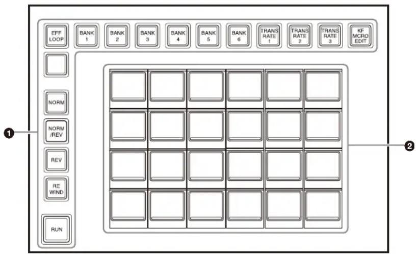
① Mode selection buttons / operation buttons / bank selection buttons (assignable buttons)
You can assign mode/bank selection buttons and effect timeline operation buttons in the Home > Setup > Panel > Module > Button Assign menu (19104.21).
For details about assigning buttons, see “Assigning Control Panel Buttons” (page 428).
Mode selection buttons
| Function name Button name Description | ||
| Transition Rate 1 to Transition Rate 3 | TRANS RATE1 to TRANS RATE3 | Switches the memory recall section to transition rate display mode. You can press a memory recall button in transition rate display mode to enter a transition rate in the numeric keypad control block. |
| Keyframe/Macro Edit | KF MCRO EDIT | Switches the memory recall section to effect timeline/macro edit mode. You can edit an effect timeline register/ macro register recalled using the numeric keypad control block. |
Effect timeline operation buttons
| Function name Button name Description | ||
| Effect Loop EFF LOOP Repeatedly executes an effect timeline. | ||
| Normal NORM Sets the effect | timeline execution direction to normal (from beginning to end). | |
| Normal/Reverse NORM/REV Sets the effect | the effect timeline execution direction to normal/reverse (toggles each time execution finishes). | |
| Reverse REV Sets the effect | timeline execution direction to reverse (from end to beginning). | |
| Rewind REWIND When the execution direction is normal, moves the effect timeline to the start point.When the execution direction is reverse, moves the effect timeline to the stop point. | ||
| Run | RUN | Executes an effect timeline. |
Bank selection buttons
| Function name Button name Description | ||
| Bank 1 to Bank 20 | BANK1 to BANK20 | Switches the memory recall section to function recall mode of the selected bank. |
② Memory recall section (memory recall buttons)
This section displays the functions assigned to the buttons for the selected operation mode.
Note
When using two utility/shotbox control blocks, the memory recall button settings are common to both.
AUX Bus Control Block
The AUX bus control block is used for selecting signals used on buses, for router operations, and other tasks. The AUX bus control block has two modes: AUX bus operation mode and router operation mode. To switch to router operation mode, press the [RTR MODE] button, turning it on, in the cross-point pad.

① Button rows
The 1st row and 2nd row are used as delegation button rows, and the 3rd row and 4th row are used as cross-point button rows.
AUX bus operation mode
Uses the 1st row and 2nd row delegation buttons to select buses, and the 3rd row and 4th row cross-point buttons to select signals.
For details, see “Chapter 4 Selecting Signals” (page 91).
Name Description
| 1st row • When second delegation mode is enabled, selects the bus to assign to the 3rd row.• When second delegation mode is disabled, selects the bus (bus in unshifted state of delegation buttons) to assign to the 3rd row and 4th row.You can select the bus in the shifted state while pressing the shift button. |
| Name Description |
| 2nd row • When second delegation mode is enabled, selects the bus to assign to the 4th row. • When second delegation mode is disabled, selects the bus (bus in shifted state of delegation buttons) to assign to the 3rd row and 4th row. |
| 3rd row • When second delegation mode is enabled, selects the signal for the bus assigned by the 1st row delegation buttons. • When second delegation mode is disabled, selects the signal for the bus assigned by the 1st row or 2nd row delegation buttons. You can select the signal in the shifted state while pressing the shift button. |
| 4th row • When second delegation mode is enabled, selects the signal for the bus assigned by the 2nd row delegation buttons. • When second delegation mode is disabled, selects the signal for the bus in the shifted state assigned by the 1st row or 2nd row delegation buttons. |
Router operation mode
Uses the 1st row and 2nd row delegation buttons to select a destination, and the 3rd row and 4th row cross-point buttons to select a source.
For details, see “Router Operations (AUX Bus Control Block)” (page 240).
| Name Description | |
| 1st row • When second delegation mode is enabled, selects the destination to assign to the 3rd row. • When second delegation mode is disabled, selects the destination (destination in unshifted state of delegation buttons) to assign to the 3rd row and 4th row. You can select the destination in the shifted state while pressing the shift button. | |
| 2nd row • When second delegation mode is enabled, selects the destination to assign to the 4th row. • When second delegation mode is disabled, selects the destination (destination in shifted state of delegation buttons) to assign to the 3rd row and 4th row. | |
| 3rd row • When second delegation mode is enabled, selects the source for the destination assigned by the 1st row delegation buttons. • When second delegation mode is disabled, selects the source for the destination assigned by the 1st row or 2nd row delegation buttons. You can select the source in the shifted state while pressing the shift button. | |
| 4th row • When second delegation mode is enabled, selects the source for the destination assigned by the 2nd row delegation buttons. • When second delegation mode is disabled, selects the source for the destination in the shifted state assigned by the 1st row or 2nd row delegation buttons. |
② Display
In AUX bus operation mode, the following information is displayed.
- Settings of buttons on the 1st row to 4th row (bus name or signal name assigned to the button)
- Macro register name of macro attachment assigned to the 1st row to 4th row buttons
- Signal name selected by the bus on the 1st row to 2nd row delegation buttons
In router operation mode, the following information is displayed.
- Settings of buttons on the 1st row to 4th row (destination name or source name assigned to the button)
- Source name selected by the destination on the 1st row to 2nd row delegation buttons
When the [SHIFT] button function is set, "SHFT" appears on the display. When the shifted state is selected, "SHFT" is displayed highlighted, and the button information also toggles to show the shifted state display.
Display mode
Six types of display mode can be set according to the information to display. You can switch the mode using the display mode button assigned to the cross-point pad. The display can also be subdivided (top and bottom) to display two pieces of information.
For details, see "Setting the Display" (page 435).
③ Cross-point indicators
When lit, these indicate the logical V/K pair color linked to the logical V/K pair assigned to buttons on the 3rd row. If a signal cannot be selected, because a signal is not assigned or the inhibit setting is set, the indicator is not lit. You can disable the cross-point indicators so that they do not turn on.
For details, see "Setting the on/off state of cross-point indicators" (page 435).
Note
In router operation mode, cross-point indicators are not used.
④ Cross-point pad (assignable buttons)
You can assign functions, such as settings and operations, of the cross-point button rows in the Home > Setup > Panel > Xpt Module > Xpt Pad Button Assign menu (19104.36).
You can configure up to 14 pages (page 1 to page 14) of settings, where each page contains functions assigned to the 15 cross-point pad buttons as a group.
For details about assigning buttons, see "Setting a Cross-Point Pad" (page 436).
For details about the method of operation, see "Cross-point pad operation" (page 24).
Assignable functions
| Function name Button name | Description |
| Others: Home | HOME Displays the home page of the cross-point pad. |
| Others: Prev | << XXX Displays the previous page of the cross-point pad.XXX = Page name (up to 12 characters) |
| Others: Next | >> XXX Displays the next page of the cross-point pad.XXX = Page name (up to 12 characters) |
| Others: Current Page Status | PAGE 1XXX to PAGE14XXXDisplays the number and name of the currently displayed page.XXX = Page name (up to 12 characters) |
| Others: Row-n Assign Status | XXX Displays the bus/function name assigned to the 1st row to 4th row.When a destination whose operation is inhibited using the NS-Bus protect function, “PROT” is displayed for the 3rd row/4th row.n = 1 to 4XXX = Bus or function name |
| Others: Xpt Holda) | XPT HOLDSets cross-point hold for the 3rd row and 4th row.In second delegation mode, sets cross-point hold for the 3rd row. |
| Others: 2nd Xpt Holda) | XPT HOLDIn second delegation mode, sets cross-point hold for the 4th row. |
| Row-3/4 Func: Row-n Xpt Button No.285 to Xpt Button No.300a) | XXX Selectsthe cross-point button number 285 to 300 signals in the 3rd row and 4th row.Re-entry signals (M/E-1 to M/E-5 Out1, P/P Out1, M/E-1 to M/E-5 Out5, P/P Out5) are assigned to button numbers 285 to 290 and 293 to 298.n = 3 or 4XXX = Signal name |
| Others: Selected Src Status | XXX Displays the signal name/source name selected by the bus/destination on the 1st row or 2nd row delegation buttons.In second delegation mode, displays the signal name/source name selected by the bus/destination on the 1st row delegation buttons.XXX = Signal name/source name |
| Others: 2nd Selected Src Status | XXX In second delegation mode, displays the signal name/source name selected by the bus/destination on the 2nd row delegation buttons.XXX = Signal name/source name |
| Function name Button name | Description | |
| Others: Display Mode 1 to Display Mode 6 | XXX Selects | display mode 1 to 6 (display mode button).XXX = Display mode name (up to 12 characters) |
| Others: Display Mode Status | DISP: XXX | Displays the currently set display mode.XXX = Display mode name (up to 12 characters) |
| Macro: Macro 1: XXX to Macro 999: XXX | XXX Recalls | macro register 1 to 999.XXX = Macro register name (up to 8 characters) |
| Others: Macro Take | TAKE Executes a macro take operation. | |
| Others: Macro Register Status | MACRO: XXX | Displays the currently recalled macro register name.The macro register name (ATTCH: XXX) of the macro attachment is displayed while the [PRE MACRO] button or [POST MACRO] button is pressed.XXX = Macro register name (up to 8 characters) |
| Others: Macro Status | EVENT XX/XX | Displays the macro status.XX/XX = Executed event number/Total number of events |
| Others: Aux Mixa) | AUX MIX Executes an AUX mix on the 3rd row and 4th row.In second delegation mode, executes an AUX mix on the 3rd row. | |
| Others: 2nd Aux Mixa) | AUX MIX In second delegation mode, executes an AUX mix on the 4th row. | |
| Others: Keya) | KEY Selects the signal on the key side in the 3rd row and 4th row.In second delegation mode, selects the signal on the key side in the 3rd row. | |
| Others: 2nd Keya) | KEY In second delegation mode, selects the signal on the key side in the 4th row. | |
| Others: 2nd Delegation | 2ND DELG Sets second delegation mode. | |
| Others: Router Mode | RTR MODE | Switches to router operation mode. |
| Others: Router Level Button 1 to Router Level Button 4b) | LEVEL BTN1 to LEVEL BTN4 | Selects the router level. |
| Function name Button name | Description |
| Others:Xpt Pad Copy | XPTPAD COPYCopies cross-point pad settings. |
a) Disabled in router operation mode. b) Disabled in AUX bus operation mode.
Control Panel Configuration (ICP-X1000 Series)
The ICP-X1000 series Compact Control Panel supports the following four types of control panel according to the number of M/E banks and cross-point buttons.
Control panel Number of M/E banks
Number of cross-point buttons
ICP-X1224 2 24
ICP-X1216 2 16
ICP-X1124 1 24
ICP-X1116 1 16
Control panel configuration example
This section describes the ICP-X1224 as an example.


① M/E banks (switcher banks)
Each bank is comprised of a cross-point control block, transition control block, and Flexi Pad control block. By default, M/E-1 and P/P switcher banks are assigned in order to the banks from the back.
The ICP-X1124 and ICP-X1116 have only one M/E bank row. By default, the P/P switcher bank is assigned to the bank.
You can change the switcher bank assignments.
For details, see “Assigning a Switcher Bank/AUX” (page 426).
② Cross-point control block (see page 50)
The ICP-X1216 and ICP-X1116 each have 16 cross-point buttons.
③ Transition control block (see page 53)
④ Flexi Pad control block (see page 55)
⑤ Device control block (see page 56)
⑥ Utility control block (see page 61)
Cross-Point Control Block
The cross-point control block is used to select the signals to be used in the switcher bank.
The button rows on the cross-point control block are set to key/AUX bus delegation mode by default.
You can set the mode to key bus mode or free assign mode in the Home > Setup > Panel > Xpt Module > Operation Mode menu (19104.31).
For details, see “Chapter 4 Selecting Signals” (page 91).

① Button rows
Name Description
| 1st row • Selects the bus or utility/shotbox bank when in key/AUX bus delegation mode. Selects the bus signal assigned by the delegation buttons in the function button section when in key bus mode or free assign mode. Selects the utility function when a utility/shotbox bank is assigned using the delegation buttons in the function button section. Selects the DME external video bus signal when in utility bus mode. Selects the background A bus signal (shifted state) when in dual background bus mode. |
| Name Description | |
| 2nd row • Selects the bus signal or utility function assigned by the 1st row delegation buttons when in key/AUX bus delegation mode. Selects the bus signal assigned by the delegation buttons in the function button section when in key bus mode or free assign mode. Selects the utility function when a utility/shotbox bank is assigned using the delegation buttons in the function button section. Selects the DME utility 1 bus or 2 bus signal when in utility bus mode. Selects the background B bus signal (shifted state) when in dual background bus mode. | |
| 3rd row • Selects the background A bus signal when in key/AUX bus delegation mode or key bus mode. Selects the bus signal assigned by the delegation buttons in the function button section when in free assign mode. Selects the utility function when a utility/shotbox bank is assigned using the delegation buttons in the function button section. Selects the utility 1 bus signal when in utility bus mode. | |
| 4th row • | Selects the background B bus signal when in key/AUX bus delegation mode or key bus mode. Selects the bus signal assigned by the delegation buttons in the function button section when in free assign mode. Selects the utility function when a utility/shotbox bank is assigned using the delegation buttons in the function button section. Selects the utility 2 bus signal when in utility bus mode. |
②Display
The display shows the following information.
- Settings of buttons on the 1st row to 4th row (signal name, bus name, register name, or function name assigned to the button)
- Macro register name of macro attachment assigned to the 1st row to 4th row buttons When the [SHIFT] button function is set, “SHFT” appears on the display. When the shifted state is selected, “SHFT” is displayed highlighted, and the button information also toggles to show the shifted state display.
Display mode
Six types of display mode can be set according to the information to display. You can switch the mode using the [DISP MODE] button assigned to the function button section. The display can also be subdivided (top and bottom) to display two pieces of information.
For details, see "Setting the Display" (page 435).
③ Cross-point indicators
When lit, these indicate the logical V/K pair color linked to the logical V/K pair assigned to buttons on the 3rd row. If a signal cannot be selected, because a signal is not assigned or the inhibit setting is set, the indicator is not lit. You can disable the cross-point indicators so that they do not turn on.
For details, see “Setting the on/off state of cross-point indicators” (page 435).
④ Function button section (assignable buttons)
You can assign functions, such as settings and operations, of the cross-point button rows in the Home > Setup > Panel > Module > Button Assign menu (19104.21).
For details about assigning buttons, see “Assigning Control Panel Buttons” (page 428).
| Function name Button name | Description | |
| Row-n Bus: Background A a) b) Background B a) b) | A B | Assigns background A and B buses to the 1st row to 4th row. n = 1 to 4 |
| Row-n Bus: Utility 1 a) c) Utility 2 a) c) | UTIL1 UTIL2 | Assigns utility 1 and 2 buses to the 1st row to 4th row. n = 1 to 4 |
| Row-n Bus: DME External a) c) | DME EXT Assigns DME external video bus to the 1st row to 4th row. n = 1 to 4 | |
| Row-n Bus: DME Utility 1 a) c) DME Utility 2 a) c) | DME UTIL1 DME UTIL2 | Assigns DME utility 1 and 2 buses to the 1st row to 4th row. n = 1 to 4 |
| Row-n Bus: Key 1 to Key 8 a) c) d) | KEY1 to KEY8 | Assigns key 1 to 8 buses to the 1st row to 4th row. n = 1 to 4 |
| Row-n Bus: Edit Preview a) b) | EDIT PVW Assigns edit preview bus to the 1st row to 4th row. n = 1 to 4 | |
| Row-n Bus: FM Source 1 a) b) FM Source 2 a) b) | FMS1 FMS2 | Assigns frame memory source 1 and 2 buses to the 1st row to 4th row. n = 1 to 4 |
| Row-n Bus: DME1 Video to DME4 Video a) b) | DME1V to DME4V | Assigns DME1 to DME4 video buses to the 1st row to 4th row. n = 1 to 4 |
| Row-n Bus: DME1 Key to DME4 Key a) b) | DME1K to DME4K | Assigns DME1 to DME4 key buses to the 1st row to 4th row. n = 1 to 4 |
| Row-n Bus: Utility/Shotbox 1 to Utility/Shotbox 10 a) c) | UTIL/ SBOX1 to UTIL/ SBOX10 | Assigns utility/shotbox banks 1 to 10 to the 1st row to 4th row. n = 1 to 4 |
| Row-n Aux: Aux 1 to Aux 48 a) b) | AUX1 to AUX48 | Assigns AUX1 to 48 buses to the 1st row to 4th row. n = 1 to 4 |
| Others: Row-n Xpt Hold d) e) | XPT HOLD Sets cross-point hold for the buses assigned to the 1st row to 4th row. n = 1 to 4 | |
| Others:Pre Macro | PRE MCROSets macro attachment in pre-macro mode. | |
| Others:Post Macro | POSTMCROSets macro attachment in post-macro mode. | |
| Others:Macro Attach Enable | MCROATTCHENBLEnables macro attachments assigned to buttons in the switcher banks. | |
| Others:Main | MAIN Switches the button operation to the function on the main side when in multi program 2 mode. | |
| Others:Sub | SUB Switches the button operation to the function on the sub side when in multi program 2 mode. | |
| Others:Display Mode | DISPMODESwitches the display mode. | |
| Others:Row-n Aux Mix a) b) | AUX MIX Executes an AUX mix when an AUX bus is assigned to the 1st row to 4th row.n = 1 to 4 | |
| Others:Aux Mix b) f) | AUX MIX Executes an AUX mix when an AUX bus is assigned to the 2nd row. | |
| Others:Row-n Key a) b) | KEY Selectsthe signal on the key side in the 1st row to 4th row.n = 1 to 4 | |
| Others:Key b) f) | KEY Selectsthe signal on the key side in the 2nd row. | |
| Others:Row-n Image Effect g) h) | IMAGE Setsthe image effect function on background A bus or B bus on the 1st row to 4th row.n = 1 to 4 | |
| Others:Row-n Protect e) | PROT Inhibits button operation on the 1st row to 4th row.n = 1 to 4 | |
| Others:Utility a) f) | UTIL Assignsthe bus when in utility bus mode to the 1st row to 4th row. | |
| Others:Shift All Bus | SHIFT ALL Switches the cross-point button rows of all buses to the shifted state. | |
| Others:Dual BKGD Bus f) | DUALBKGD BUSSwitches to dual background bus mode. | |
| Others:Xpt Inhibit | INHBT SET Sets/releases inhibit mode for cross-point buttons. | |
| Function name | Button name | Description |
| Others:Xpt Inhibit All Clear | INHBT ALLCLR | Releases inhibit mode for all cross-point buttons. |
a) Disabled in key/AUX bus delegation mode. b) Disabled in key bus mode. c) 3rd row and 4th row are disabled in key bus mode. d) Disabled for SL keys. c) 1st row is disabled in key/AUX bus delegation mode. f) Disabled in free assign mode. g) 1st row and 2nd row are disabled in key bus mode. h) 1st row and 2nd row are disabled in key/AUX bus delegation mode.
Transition Control Block
The transition control block is used to execute transitions. It supports common transitions and independent key transitions.
For details, see "Chapter 5 Transitions" (page 104).

① Transition execution section
| Name Description | |
| Fader lever Move this up or down to execute a transition. | |
| Transition indicator | Displays the transition progress using LEDs. |
| [AUTO TRANS] button | Executes an auto transition with the set transition rate and transition type.During the transition, the button is lit amber. |
| [CUT] button Executes an immediate transition. | |
② Transition settings section (assignable buttons) You can assign functions, such as selections and settings, for transitions in the Home > Setup > Panel > Module > Button Assign menu (19104.21).
For details about assigning buttons, see "Assigning Control Panel Buttons" (page 428).
Next transition selection buttons
| Function name | Button name | Description |
| Background BK | GD Switches the | background for a next transition. |
| Key 1 to Key 8 | KEY1 to KEY8 In | inserts or removes the selected key for a next transition.The key is inserted if a key is currently not inserted, or removes the key if a key is currently inserted. |
| Key Priority KEY | PRIOR Changes | the key priority for a next transition.When the [PRIOR SET] button is lit, the setting for key priority after the transition is used. |
| All ALL Selects | multiple next | transitions simultaneously. |
| Priority Set | PRIOR SET | Sets the key priority. |
Transition type selection buttons
| Function name | Button name | Description |
| Mix MIX Selects | mix. | |
| NAM NAM Selects | NAM (non-additive mix). | |
| Super Mix SUPER | MIX Selects | super mix. |
| Preset Color Mix | PST COLOR MIX | Selects preset color mix. |
| Wipe WIPE Selects | wipe. | |
| DME Wipe DME | WIPE Selects | DME wipe. |
| FM 1&2 Clip to FM 15&16 Clip | FM1&2 CLIP to FM15&16 CLIP | Selects clip transition. |
Wipe direction selection buttons
| Function name | Button name | Description |
| Normal NORM | The wipe proceeds in the direction from black to white of the pattern images, shown in “Wipe Pattern List” (page 538), or in the direction of the arrows (normal). | |
| Normal/Reverse | NORM/REV | The wipe direction alternates between normal and reverse after each transition. |
| Reverse | REV | The wipe proceeds in the opposite direction of normal (reverse). |
Transition preview buttons
| Function name | Button name | Description |
| Transition Preview | TRANS PVW | Switches the transition preview mode.You can check a transition using preview output. |
Pattern limit setting buttons
| Function name | Button name | Description |
| Limit Set | LIMIT SET | Sets the pattern limit. |
| Pattern Limit | PTN LIMIT | Enables the pattern limit. |
Main/sub switching buttons (multi program 2 mode)
| Function name | Button name | Description |
| Main | MAIN | Switches operation to the function on the main side in multi program 2 mode. Simultaneously pressing the [SUB] button activates both the main and sub operations. |
| Sub SUB | Switches operation to the function on the sub side in multi program 2 mode. | |
③ Display
The display shows the following information.
- Left-side display: Target switcher bank name (M/E1 to M/E5, P/P) Main and sub assignment status when in multi program 2 mode (MAIN, SUB, MAIN&SUB)
- Right-side display: Transition rate During key priority setting operation, the display shows the following information.
- Left-side display: State (displayed highlighted when on) and priority of key 1 to key 4 Main and sub assignment status when in multi program 2 mode (M, S)
- Right-side display: State (displayed highlighted when on) and priority of key 5 to key 8 Main and sub assignment status when in multi program 2 mode (M, S)
4 Independent key transition execution section (assignable buttons)
You can assign execution buttons for independent key transitions in the Home > Setup > Panel > Module > Button Assign menu (19104.21).
For details about assigning buttons, see "Assigning Control Panel Buttons" (page 428).
| Function name | Button name | Description |
| Key 1 Transition to Key 8 Transition | KEY1 TRANS to KEY8 TRANS | Inserts or removes a key automatically with the set transition rate and transition type. During the transition, the button is lit amber. |
| Key 1 On to Key 8 On | KEY1 ON to KEY8 ON | Inserts or removes a key instantaneously. If a key is currently inserted, the button is lit amber. |
Flexi Pad Control Block
The Flexi Pad control block is used for recalling and saving snapshots, wipe snapshots, DME wipe snapshots, key snapshots, and panel memory, for recalling and creating macros, for recalling shotboxes, for entering the transition rate, and for other tasks.
![graph TD subgraph Module_1 A["KEY"] --> B["WIPE"] B --> C["DME WIPE"] C --> D["SNAP SHOT"] D --> E["PNL MEM"] E --> F["SHOT BOX"] F --> G["MCRO"] end subgraph Module_2 H["UNDO"] --> I["DEL"] I --> J["TRANS RATE"] J --> K["BANK 0"] J --> L["BANK 1"] J --> M["BANK 2"] J --> N["BANK SEL"] end Module_1…](/content/2026/06/1382172/images/73d135616f59b43ed2aeb448f483dee5467b56dd84f9106a63bc6eb55ce30a78.jpg)
① Mode selection buttons / operation buttons / bank selection buttons (assignable buttons)
You can assign mode/bank selection buttons and operation buttons in the Home > Setup > Panel > Module > Button Assign menu (19104.21).
For details about assigning buttons, see “Assigning Control Panel Buttons” (page 428).
Mode selection buttons
| Function name | Button name | Description |
| Key KEY Switches to key operation mode.In key operation mode, you can carry out the following operations.Saving and recalling key snapshotsSelecting independent key transition typeSelecting the key fill signal or key source signal in the cross-point control block | ||
| Function name | Button name | Description |
| Wipe WIPE Switches to wipe | snapshot operation mode.In wipe snapshot operation mode, you can save and recall a wipe snapshot and select a wipe pattern. | |
| DME Wipe DME WIPE Switches | to DME wipe snapshot operation mode.In DME wipe snapshot operation mode, you can save and recall a DME wipe snapshot and select a DME wipe pattern. | |
| Snapshot SNAPSHOT Switches | to snapshot operation mode.In snapshot operation mode, you can save and recall snapshots, and add attributes. | |
| Panel Memory PNL MEM Switches to panel memory operation mode.In panel memory operation mode, you can save and recall panel memory. | ||
| Shotbox SHOTBOX Switches to shotbox operation mode.In shotbox operation mode, you can recall and execute shotboxes. | ||
| Macro | MCRO | Switches to macro operation mode.In macro operation mode, press and hold the [MCRO] button and press a button (for the target register) in the memory recall section to enter edit mode.In macro operation mode, you can save, recall, and edit macros. |
| Transition Rate | TRANS RATE | Switches to transition rate operation mode.In transition rate operation mode, you can enter a transition rate. |
[UNDO] button / [DEL] button
| Function name | Button name | Description |
| Undo | UNDO | After recalling a register, returns to the state before the register was recalled. |
| Delete DEL Press and hold the [DEL] button and press a register button in the memory recall section to delete the register data. | ||
Notes
- The [UNDO] button and [DEL] button cannot be used in shotbox operation mode.
- The [UNDO] button cannot be used in macro operation mode. Also, the [DEL] button cannot be used in edit mode.
- The [UNDO] button cannot be used in panel memory operation mode.
Bank selection buttons
| Function name | Button name | Description |
| Bank 0 to Bank 99 | BANK0 to BANK99 | The memory recall section switches to the register display for the selected bank. |
| Bank Select BANK SEL Enter a | bank number to switch the memory recall section to the register display for the selected bank. | |
②Memory recall section (memory recall buttons)
This section displays the functions assigned to the buttons for the selected operation mode.
The top right button is used to display the selected pattern number, register number, macro event number, transition rate input value, and other status display (excluding in key operation mode).
When a macro is recalled in macro operation mode, the bottom center button displays the executed event number and the total number of events.
Numeric keypad mode
Pressing the [BANK SEL] button, [PTN NO.] button, or [PAUSE] button switches the memory recall section to numeric keypad mode, where you can enter bank numbers, wipe pattern numbers, and pause event times. The currently set numeric value or the value entered in numeric keypad mode is displayed on the top right button.
Device Control Block
The device control block is used for three-dimensional transforms using a DME, two-dimensional transforms using a resizer, executing effect timelines, controlling
devices/frame memory/clip players, entering menu parameters, and other functions.
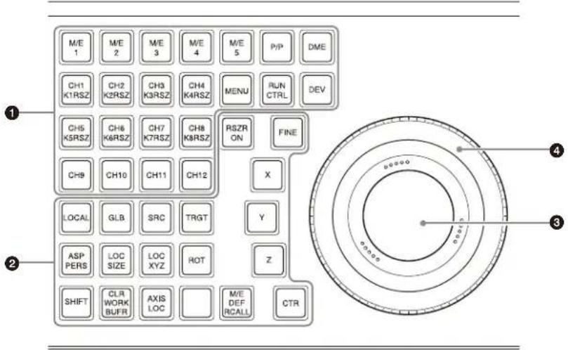
① Mode selection buttons / channel selection buttons (assignable buttons)
You can assign mode and channel selection buttons in the Home > Setup > Panel > Module > Button Assign menu (19104.21).
For details about assigning buttons, see “Assigning Control Panel Buttons” (page 428).
Mode selection buttons
| Function name | Button name | Description |
| Menu MENU • Switches to menu | parameter operation mode.You can adjust parameters (numbers 1 to 3) of the currently displayed menu using the trackball and Z-ring.Press the [MENU] button twice, turning it on green, to fix the target of the trackball and Z-ring to the parameter currently being adjusted. | |
| Run Control RUN CTRL • Switches to run control operation mode.Enables operation of the currently recalled effect timeline using the Z-ring. | ||
| M/E-1 to M/E-5 P/P | M/E1 to M/E5 P/P | • Switches to resizer operation mode.The first selected button becomes the reference, and is lit green. Subsequent selected buttons are lit amber. |
| DME DME Switches to three- | dimensional transform operation mode. | |
| Device DEV Switches to device/frame memory/clip player operation mode. | ||
Channel selection buttons
| Function name | Button name | Description |
| Channel 1 to Channel 12 | CH1 to CH12 | CH1 to CH4: Selects the target DME channel in three-dimensional transform operation mode. CH1 to CH12: Selects the target device in device/frame memory/clip player operation mode. |
| K1 Resizer to K8 Resizer | K1RSZ to K8RSZ | Selects the target resizer in resizer operation mode. |
| FM 1 Clip to FM 16 Clip | FM1 CLIP to FM16 CLIP | Selects the target frame memory output channel in device/frame memory/clip player operation mode. |
| Clip Player 1 to Clip Player 4 | CLIP1 to CLIP4 | Selects the target clip player output channel in device/frame memory/clip player operation mode. |
Notes
- When multiple channels are selected, the first selected button becomes the reference, and is lit green. Subsequent selected buttons are lit amber.
- [CH1] to [CH8] and [K1RSZ] to [K8RSZ] share the same buttons.
②Operation buttons (assignable buttons)
You can assign buttons for use in each operation mode in the Home > Setup > Panel > Module > Button Assign menu (19104.21).
For details about assigning buttons, see “Assigning Control Panel Buttons” (page 428).
Resizer operation mode
This mode is used for two-dimensional transform operations on images using a resizer.
For details about resizer operations, see "Resizer" (page 147).
| Function name | Button name | Description |
| Aspect/Perspective | ASP PERS Adjusts the aspect ratio of a key using the trackball or Z-ring. | |
| Location Size | LOC SIZE | Moves a key using the trackball.Scales a key (shrink/magnify) using the Z-ring. |
| Rotation ROT | Rotates a key using the trackball.Adjusts the perspective of a key using the Z-ring. | |
| Shift SHIFT Used in combination with the [CTR], [CLR WORK BUFR], and [BDR/CROP] buttons. | ||
| Clear Work Buffer | CLR WORK BUFR | When the [CLR WORK BUFR] button is pressed once:Returns the two-dimensional transform parameters to the initial settings.When the [CLR WORK BUFR] button is pressed twice, or the [CLR WORK BUFR] button is pressed once while pressing the [SHIFT] button:Returns all resizer parameters to the initial settings. |
| Resizer On RSZR ON | Enables/disables the selected resizer. | |
| Function name | Button name | Description |
| X | X | Restricts the parameters targeted by the operation.When the [X] button is lit:Operations on parameters on the X-axis using the trackball are enabled.When the [Y] button is lit:Operations on parameters on the Y-axis using the trackball are enabled.When the [Z] button is lit:Operations on parameters on the Z-axis (Z-ring adjustment items) using the Z-ring are enabled.When the [ROT] button is lit, the [X] button and [Y] button select the direction of rotation.When the [BDR/CROP] button is lit green, the [X] button, [Y] button, and [Z] button select the edge (top edge, left edge, right edge) to crop. |
| Y | Y | |
| Z | Z | |
| Fine FINE Switches to fine mode,enabling fine adjustment control of setting values using the trackball and Z-ring. | ||
| M/E Default Recall | M/E DEFRCALL | When the [M/E DEFRCALL] button is pressed twice:Returns the switcher bank to the initial settings. |
| Center CTR • When the [CTR] button | ||
| Border/Crop BDR/CROP • When the [BDR/CROP] button is pressed (lit amber):Adjusts the border width of a key using the trackball or Z-ring.When the [BDR/CROP] button is pressed while pressing the [SHIFT] button (lit green):Adjusts the crop width of a key using the Z-ring. | ||
Three-dimensional transform operation mode
This mode is used for three-dimensional transform operations on images using a DME.
For details about DME operations, see "Three-Dimensional Transforms" (page 209).
| Function name | Button name | Description |
| Local LOCAL Selects local space. | ||
| Global GLB Selects global space. | ||
| Source SRC Selects source space. | ||
| Target TRGT Selects target space. | ||
| Function name | Button name | Description |
| Aspect/Perspective | ASP PERS • When the [ASP PERS] button is pressed in source space: Adjusts the aspect ratio of an image using the trackball or Z-ring.When the [ASP PERS] button is pressed while pressing the [SHIFT] button in source space: Adjusts the skew of an image using the trackball.When the [ASP PERS] button is pressed in target space: Adjusts the viewpoint position (perspective of an image) using the trackball or Z-ring. | |
| Location Size | LOC SIZE | Moves an image using the trackball.Scales an image (shrink/magnify) using the Z-ring. |
| Location XYZ | LOC XYZ | Moves an image using the trackball or Z-ring. |
| Rotation | ROT Rotates an image using the trackball or Z-ring. | |
| Shift SHIFT Used in combination with the [ASP PERS], [ROT], [CTR], and [CLR WORK BUFR] buttons. | ||
| Clear Work Buffer | CLR WORK BUFR | When the [CLR WORK BUFR] button is pressed once: Returns the three-dimensional transform parameters to the initial settings.When the [CLR WORK BUFR] button is pressed twice, or the [CLR WORK BUFR] button is pressed once while pressing the [SHIFT] button: Returns all DME parameters to the initial settings. |
| Axis Location | AXIS LOC | Moves the rotation axis of an image using the trackball or Z-ring. |
| X | X | Restricts the parameters targeted by the operation. |
| Y | Y | |
| Z | Z | When the [X] button is lit: Operations on parameters on the X-axis using the trackball are enabled.When the [Y] button is lit: Operations on parameters on the Y-axis using the trackball are enabled.When the [Z] button is lit: Operations on parameters on the Z-axis (Z-ring adjustment items) using the Z-ring are enabled. |
| Fine FINE Switches to fine mode,enabling fine adjustment control of setting values using the trackball and Z-ring. | ||
| Center CTR • When the [CTR] buttonis pressed once:Adjusts the three-dimensional transform parameters to the detent positions.When the [CTR] button is pressed twice, or the [CTR] button is pressed once while pressing the [SHIFT] button:Returns the three-dimensional transform parameters to the default values. | ||
Menu parameter operation mode
Used to set menu parameters.
For details about menu parameter operations, see
"Setting Parameters" (page 81).
| Function name | Button name | Description |
| X | X | Restricts the parameters targeted by the operation. |
| Y | Y | |
| Z | Z | When the [X] button is lit: Operations on parameter number 1 using the trackball are enabled.When the [Y] button is lit: Operations on parameter number 2 using the trackball are enabled.When the [Z] button is lit: Operations on parameter number 3 using the Z-ring are enabled. |
| Function name | Button name | Description |
| Fine FINE Switches to fine mode,enabling fine adjustment control of setting values using the trackball and Z-ring. | ||
Device/frame memory/clip player operation mode
This mode controls operations of devices such as VTRs/disk recorders and operations of frame memory/clip players.
For details about device operations, see "Control of VTRs and Disk Recorders" (page 227).
For details about frame memory operations, see "Playing Video" (page 194).
For details about clip player operations, see "Playing Video" (page 201).
This adjusts the parameters of items selected in resizer operation mode, three-dimensional transform operation mode, and menu parameter operation mode.
④Z-ring
This adjusts the parameters of items selected in resizer operation mode, three-dimensional transform operation mode, and menu parameter operation mode.
It is used for playback operations in device/frame memory/clip player operation mode.
It can control an effect timeline in run control operation mode.
Utility Control Block
The utility control block is used to execute functions assigned to memory recall buttons, execute effect timelines, and enter menu parameters.
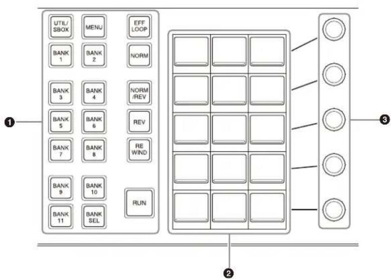
① Mode selection buttons / operation buttons / bank selection buttons (assignable buttons)
You can assign mode/bank selection buttons and effect timeline operation buttons in the Home > Setup > Panel > Module > Button Assign menu (19104.21).
For details about assigning buttons, see "Assigning Control Panel Buttons" (page 428).
Mode selection buttons
| Function name | Button name | Description |
| Utility/Shotbox | UTIL/SBOX Switches to utility/shotbox operation mode.You can execute functions assigned to the memory recall section. | |
| Menu MENU | Switches to menu | parameter operation mode.You can adjust parameters (numbers 1 to 5) of the currently displayed menu using the adjustment knobs. |
Effect timeline operation buttons
| Function name | Button name | Description |
| Effect Loop EFF | LOOP Repeatedly executes an effect timeline. | |
| Normal NORM | Sets the effect timelinecomuction direction to normal (from beginning to end). | |
| Normal/Reverse | NORM/REV Sets the effect timeline execution direction to normal/reverse (toggles each time execution finishes). | |
| Reverse REV S | Sets the effect timelinecomuction direction to reverse (from end to beginning). | |
| Rewind REWIND | When the execution direction is normal, moves the effect timeline to the start point.When the execution direction is reverse, moves the effect timeline to the stop point. | |
| Run | RUN | Executes an effect timeline. |
Bank selection buttons
| Function name | Button name | Description |
| Bank 1 to Bank 20 | BANK1 to BANK20 | Switches the memory recall section to function recall mode of the selected bank. |
| Bank Select BANK SEL Entering | a bank number switches the memory recall section to function recall mode of the selected bank. | |
②Memory recall section (memory recall buttons)
This section displays the functions assigned to the buttons for the selected operation mode.
Numeric keypad mode
Pressing the [BANK SEL] button switches the memory recall section to numeric keypad mode, where you can enter bank numbers.
The currently set numeric value or the value entered in numeric keypad mode is displayed on the top right button.
Enter a bank number and press the [ENTER] button to switch the memory recall section to the display for the selected bank.
③ Adjustment knobs 1 to 5
Used to set menu parameters.
Power Supply and Connectors
MLS-X1 Live Production Processor
Front view

① Power button
Turns the box on/off.
The button is lit when turned on.
② Front panel LED
Displays the status of the box by the color and flash rate of the LED.
Normal operation: Lit blue
While starting/shutting down/updating firmware: Flashing
When an error occurs: Lit red
When a warning occurs: Lit amber
When beacon is operating: Flashing white for 5 seconds
③Display
Displays the box model, settings, and other information. Also used when configuring the IP address, using MLS Manager, and resetting the password.
You can switch the display items using the [SELECT] button.
Note
Each time the [SELECT] button or [SET] button is pressed, the display flashes several times. This is not a malfunction.
For details, see “Display items and operations” (page 63).
④SET button
Used when executing items shown on the display.
⑤SELECT button
Selects the display items shown on the display.
The next item is shown each time the [SELECT] button is pressed.
Status indicators
Displays the status by the color of the LEDs. Lit green during normal operation.
REF indicator: Reference status
Lit red when an error occurs.
FAN indicator: Fan status
Lit red when an error occurs and lit amber when a warning occurs.
COM indicator: Box status (excluding reference, fan, and network)
Lit red when an error occurs and lit amber when a warning occurs.
NETWORK indicator: Network status
Lit red when an error occurs and lit amber when a warning occurs.
Display items and operations
The following eight items are displayed in sequence each time the [SELECT] button is pressed.
- Model name of the box (MLS-X1)
- Host name of the box
- IP/Mac Address:
Displays the IPv4 addresses and MAC addresses of standard interfaces 1 and 2.
- Device Info: Displays the serial number, version, and box input/output type (M/E-IP, M/E-SDI, M/E-mix, Half-IP, Half-SDI, M/E-none, XPT-IP, XPT-SDI, XPT-none) of the box.
- Config Info Displays information about the boxes configured in a switcher.
• PBID (physical box ID): 1 to 5, N/A
- Group: 1 to 4, N/A
• LBID (logical box ID): 1 to 5, N/A
- MMgr: Enable, Disable
- MLS Manager: Configures MLS Manager settings. Press the [SET] button to display [Enable] and [Disable]. Press the [SELECT] button to select an item, and press [SET] to apply the setting.
- Initialize: Initializes the IP address and system setup. Pressing the [SET] button displays an execution confirmation message. Press the [SET] button to execute initialization. To cancel execution, press the [SELECT] button.
- Password Reset: Resets the password of the administrator user account.
Note
Only the primary box (LBID: 1) is displayed.
For details, see “Resetting the password of the administrator user account” (page 76).
- MMgr Initialize: Initializes the MLS Manager. Pressing the [SET] button displays an execution confirmation message. Press the [SET] button to execute initialization. To cancel execution, press the [SELECT] button.
Note
Only boxes on which MLS Manager is enabled are displayed.
- M M gr Pass w d R s t : Resets the MLS Manager password.
Note
Only boxes on which MLS Manager is enabled are displayed.
Rear view
When MKS-X1110 IP Input & Output Boards are installed
Cross-point box
Half box
M/E box
①LAN 1-1, 1-2, 2-1, 2-2 connectors (QSFP28 type)
Connectors for transmitting IP signals (ST 2110 stream). Connectors with names with an odd-number suffix (primary) and an even-number suffix (redundant) support network redundancy.
Both input signals and output signals can be transmitted with a single LAN connector. Also, multiple video signals are multiplexed and transmitted using a single LAN connector.
Both input signals and output signals can have a format converter configured on the odd-numbered ports of video signals.
Output signals, including the program outputs, preview outputs, and AUX outputs, are assigned and output as IP signals (ST 2110 stream).
Output signals are either an “Output” or “Dedicated Output” type, depending on the type of the assigned signal.
For details, see "Setting the Output Signal" (page 396).
For details about input/output numbers, see "Input/Output Numbers" (page 550).
②XPT PORT A to C connectors (QSFP28 type)
Used when building an island with multiple boxes. Connectors for connecting the cross-point box and M/E boxes using interconnection cables. XPT PORT in slot number 1 of the cross-point box is not used. Do not connect it to anything.
For details about connecting, refer to the MLS-X1 Installation Manual.
③GPI connector (D-Sub 25-pin)
Used as a GPI input port and GPI output port. Can also be used as a tally input/output port.
④LAN1 connector (RJ-45, 1000BASE-T compliant)
LAN connector for standard interface 1. Used to control devices connected to the network of the switcher system.
⑤LAN2 connector (RJ-45, 1000BASE-T compliant)
LAN connector for standard interface 2.
Used to connect with an external network.
⑥REF connectors (BNC type)
Connect to a tri-level sync signal or black burst signal when using the unit synchronized to an external reference signal.
The two connectors are loop-through connectors. Whichever is used as the input signal, the other can be used as an output signal. When not using loop-through, terminate the unused connector using a 75 ohm terminator.
⑦ REF OUT connector (BNC type)
Outputs the internal reference signal when an external reference signal is not being used.
⑧ connector (USB 3.0, Type A)
Used for service purposes.
⑨ connector (USB 2.0, Type A)
Used for service purposes.
⑩ (signal ground) terminal
Connect to a ground wire.
⑪ AC IN A, B, C, D connectors
Connect to an AC power supply using an AC power cord (sold separately).
⑫ GPI 1 and 2 connectors (D-Sub 25-pin)
Can be used when an MKS-X1700 Legacy Interface Board (option) is installed.
Used as a GPI input port and GPI output port.
Can also be used as a tally input/output port.
⑬ Network expansion 4 connector
14 Network expansion 3 connector
15 Network expansion 2 connector
16 Network expansion 1 connector
PCIe slot. Supports third-party network expansion cards.
Used as interface expansion 1 to 4 LAN connectors.
The connectors are numbered 1 to 4 or 4 to 1 depending on the product.
For details about recommended products, consult your Sony representative.
For details, see “Configuring Box Network Settings” (page 499).
17 REMOTE 1/2, 3/4, 5/6, 7/8 connectors (RJ-45, RS-422 compliant)
Can be used when an MKS-X1700 Legacy Interface Board (option) is installed.
Connect to a device that supports VTR (Sony 9-pin VTR protocol), disk recorder (Video Disk Communications Protocol, Odetics protocol), or P-Bus (Peripheral Bus II protocol) protocols.
Can also be used as a tally output port.
When MKS-X1115 SDI Input & Output Boards are installed
For details about common parts, see "When MKS-X1110
IP Input & Output Boards are installed" (page 65).
Cross-point box
Half box
M/E box
① OUTPUT connectors (BNC type)
Program outputs, preview outputs, and AUX outputs can be assigned and output as serial video signals.
A format converter can be configured on the odd-numbered ports of video signals. Signals are either an “Output” or “Dedicated Output” type, depending on the type of the assigned signal.
For details, see "Setting the Output Signal" (page 396).
For details about output numbers, see “Input/Output Numbers” (page 550).
②XPT PORT A to C connectors (QSFP28 type)
Used when building an island with multiple boxes.
Connectors for connecting the cross-point box and M/E boxes using interconnection cables.
XPT PORT in slot number 1 of the cross-point box is not used. Do not connect it to anything.
For details about connecting, refer to the MLS-X1 Installation Manual.
③INPUT connectors (BNC type)
Inputs serial video signals.
A format converter can be configured on the odd-numbered ports of video signals.
When the system signal format is 2160P, only odd-numbered connectors are enabled. The port numbers for odd-numbered connectors 1, 3, 5, 7 and so on become 1, 2, 3, 4 and so on.
For details, see "Setting the Input Signal" (page 390).
For details about input numbers, see "Input/Output Numbers" (page 550).
ICP-X7000 Control Panel
Bottom view
ICP-X7000 Integrated Control Panel

MKS-X7075 Extension Adaptor

①DC IN connector
Connect to the supplied AC adaptor.
② LAN connector (RJ-45, PoE+, 1000BASE-T compliant)
Connect to the switcher system network via an Ethernet switch.
Operation without using the AC adaptor is supported using a PoE+ (Power over Ethernet Plus) compatible Ethernet switch.
For details about PoE+ (Power over Ethernet Plus) compatible Ethernet switches that can be used, consult your Sony representative.
Side view
ICP-X7000 Integrated Control Panel MKS-X7075 Extension Adaptor

①m (signal ground) terminal
Connect to a ground wire.
ICP-X1000 Series Control Panel
Rear view
The following illustration shows the ICP-X1224.

①DC IN A and B connectors
Connect to the supplied AC adaptor.
② (signal ground) terminal
Connect to a ground wire.
③LAN A1 connector (RJ-45, 1000BASE-T compliant)
Connect to the switcher system network via an Ethernet switch.
Connect to the switcher in system configurations that do not use an Ethernet switch.
④ LAN A2 connector (RJ-45, 1000BASE-T compliant)
Connect to a computer for menu operations in system configurations that do not use an Ethernet switch.
⑤ LAN B connector (RJ-45, 1000BASE-T compliant)
Used for LAN A1 connector redundancy.
Menu
The menu is used to configure data management, setup, and other settings related to the switcher and control panel. It can also be used to configure transitions, keys, and image creation settings using menu operations.
For details about menu operations, see "Chapter 3 Menu Operation" (page 74).
Screen Structure
Header area
①Home button
Displays the Home > Shortcut > Top Menu List menu (10301.11).
Press the [←] button to go back to the previously recalled menu. Press the [→] button to go forward.
Press and hold a button to display a pull-down list to select and recall a menu from the history.
③Menu number button
Displays the menu number. A heart-shaped icon is displayed for menus registered as favorites.
Press the menu number button to display the numeric keypad window, and enter a menu number to recall the corresponding menu.
④Menu path
Displays the menu path.
⑤ Macro edit indicator button
Displays [Menu Macro Enbl] during macro editing using the menu when auto insert mode is disabled.
You can execute a macro using panel operations.
Displays [Macro Auto Ins] during macro editing using the menu when auto insert mode is enabled and displays a red frame in the header area.
When you recall a macro register using a panel operation, all events of the target register are inserted into the register being edited.
If macro execution is prohibited under the following conditions, [Macro Rel Proh.] is displayed.
- When editing a macro using a panel
- In menus not in macro edit mode when multiple menus are open and auto insert mode is enabled in a menu in macro edit mode
Pressing the macro edit indicator button opens the Home > Register > Macro > Edit Macro menu (18307.11).
⑥ Unapplied / unsaved indicator
Displays [Unapplied *] when there is a setting value not applied in the menu.
Displays [Unsaved *] when there is content that is not saved in content storage.
⑦ Panel link button
The connected control panel (1 or 2) and a link icon are displayed.
Press the panel link button to link the control panel with the menu.
For details, see “Linking a Control Panel with the Menu” (page 87).
⑧Messages indicator button
Displays the number of messages when there is updated error information.
Press the messages indicator button to check information about the occurrence of errors.
⑨Overflow button
Displays items that are not displayed in the header area.
Press the overflow button to display a pull-down list to select the following items.
System Configuration
Displays the System Configuration menu.
User's Guide
Displays the MLS-X1 User's Guide.
End-User License Agreement
Displays the software license information (end user license agreement).
System Shutdown
Shuts down the system.
System Reboot
Reboots the system.
Sign Out
Signs out from the MLS-X1 menu.
Menu selection area
Selects the 2nd, 3rd, 4th, and 5th level in the menu hierarchy.
For details, see "Menu Selection" (page 78).
Menu display area
Displays the menu operation buttons, target list of operations, status of settings, and other information.
When adjusting parameters, an analog controls section appears on the right.
For details, see "Basic Menu Operation" (page 78).
Taskbar area
Displays shortcuts for frequently used menus and functions commonly used in parallel with the current menu.
Five types of taskbar can be used.
For details, see "Switching Taskbars" (page 85).
Default recall button
The [Default Recall] button is displayed for menus which can be returned to their initial settings.
For details, see "Initializing Settings (Default Recall)" (page 85).
Pop-up Window
Depending on the menu button, a pop-up window may be displayed in the menu display area when the button is pressed.
Numeric keypad window
Displays a numeric keypad for entering numeric values.
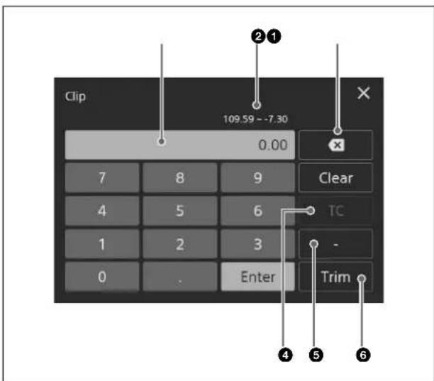
①Display (input value display area)
Displays the numeric value entered using the numeric keypad.
When you press the display area, the cursor appears and you can also enter numeric values using the keyboard.
②Setting range
Displays the minimum and maximum values for settings with a range.
③Backspace button
Deletes the rightmost number/character of an entered value.
④[TC] button
Changes the input mode to enter timecode values. Set to the on state for timecode input mode, and set to the off state for frame number input mode.
For details, see "Timecode input and frame number input" (page 88).
⑤[-] (minus) button
Changes the sign of the input value. Set to the on state for negative values.
⑥[Trim] button
Changes a setting value by the entered difference value.
For details, see “Entering a difference from a current value” (page 88).
Setting / selection window
Displays operation buttons and input fields used to set functions and select the target of operations.
Analog controls window
Displays an analog controls section for adjusting parameters.
For details, see "Analog controls window" (page 81).
Message window
Displays operation confirmations and other messages, as required.
Menu Operation
Chapter
3
Overview
The MLS-X1 menu is a web-based application.
The menu can be operated using the touch panel of a computer (tablet or PC) connected to the switcher system network. The menu can also be operated using a mouse. In this manual, "press" is used to indicate a tap or click operation of menu buttons.
Note
Some menus require administrator privileges to operate.
Menu Operating Environment
Notes
- Operation is not guaranteed with all combinations of operating systems and browsers.
- Menu operation may be different or the menu may not function correctly depending on the peripheral devices used, such as mouse and keyboard.
- Connect using encrypted communication (https://) when accessing the URL of the menu.
- Operation cannot be guaranteed if there are five or more tabs open in the browser.
Recommended operating environment
Browser:
Google Chrome 135.0.7049.85 or later (update to the latest version for use)
Safari 18.4 or later (update to the latest version for use)
Display size:
12.9 inches or larger
Verified operating environment
Windows 10 Version 22H2
Windows 11 Version 23H2
Browser: Google Chrome version 135.0.7049.85
(64-bit)
iPadOS version 18.4
Browser: Safari version 18.4
Number of clients that can be connected simultaneously
Up to 32 clients counting Virtual Shot Box are supported. (If MLS Manager is running on the primary box, up to 32 clients counting the MLS Manager menu)
Notes
- One client corresponds to one browser tab.
- The maximum number of connections from a single browser to the same MLS-X1 is 3 clients (3 tabs), counting Virtual Shot Box. (If MLS Manager is running on the primary box, up to 3 clients counting the MLS Manager menu.)
Installing a Root Certificate
A root certificate must be installed on the computer in order to use the menu.
Note
If a root certificate has been installed for the MLS Manager menu or Virtual Shot Box, it does not need to be reinstalled.
1 Access the certificate download page.
Enter the URL of the certificate download page in a browser. "http://IP address of download page/doc/Certificate/"
Note
Enter one of the following IP addresses of logical box 1 (primary box) of the logical switcher to connect as the IP address of the certificate download page.
- IP address displayed on the control panel display
- Address of standard interface 1 of logical box 1 (primary box) of the logical switcher to connect, which is set in the MLS Manager Home > System > Island > Box Network menu (60211.05) of MLS Manager
For details about settings, see "Configuring Box Network Settings" (page 499).
It is set to "192.168.100.1" by default.
2 Download a root certificate.
3 Install the root certificate.
Note
The installation method may vary depending on your computer (tablet or PC). For details about installing a certificate, refer to the operating instructions for the computer.
Signing In / Signing Out
When signing in for the first time using an administrator account
By default, “admin” is the only administrator user account registered.
When signing in for the first time, enter “admin” for the user name and “admin” for the password, and press [Sign In].
The software End User License Agreement confirmation window appears. Press the [Agree] button if you accept the conditions.
When you agree, a change password message appears.
Press [OK] and change the password.
Note
The password must be 8 to 32 characters, containing at least one single-byte alphabetic character and at least one single-byte numeric character.
Signing in to the MLS-X1 menu
1 Access the MLS-X1 menu.
Enter the URL of the MLS-X1 menu in a browser.
https://IP address of MLS-X1 menu/
The MLS-X1 menu sign-in screen appears.
Note
Enter one of the following IP addresses of logical box 1 (primary box) of the logical switcher to connect as the IP address of the MLS-X1 menu.
- IP address displayed on the control panel display
- Address of standard interface 1 of logical box 1 (primary box) of the logical switcher to connect, which is set in the MLS Manager Home > System > Island > Box Network menu (60211.05) of MLS Manager
For details about settings, see “Configuring Box Network Settings” (page 499).
It is set to “192.168.100.1” by default.
2 Enter your user name and password, and press [Sign In].
The panel selection screen appears.
To enter your user name automatically when signing in
Place a check mark in [Remember username].
To change the password
Change the password in the System Configuration > User Account > Manage Users menu (20601.11).
For details, see “Changing a user account password” (page 486).
3 Select a control panel to connect and press [OK].
The menu screen appears.
Note
A security warning message may appear when displaying the menu screen, but continue the operation.
Signing out from the MLS-X1 menu
Press the overflow button in the header area and select [Sign Out] from the pull-down list.
Resetting the password of the administrator user account
You can reset the password of the “admin” administrator user account to the initial setting (“admin”).
The password is reset using the display and buttons on the front panel of the switcher.
For details about the display and buttons, see “Front view” (page 63).
1 Press the [SELECT] button until the [Password Reset] item appears on the display.
The display item changes each time the [SELECT] button is pressed.
2 Press the [SET] button.
An execution confirmation message appears.
3 Press the [SET] button.
The password is reset. To cancel execution, press the [SELECT] button.
Displaying the User's Guide
You can display the User's Guide in English or Japanese. Press the overflow button in the header area and select [User's Guide] from the pull-down list.
Select a language on the User's Guide link screen to display the User's Guide.
To display the User's Guide from the sign-in screen
Press the overflow button displayed on the top right of the sign-in screen and select [User's Guide] from the pull-down list.
Displaying License Information
Press the overflow button in the header area and select [End-User License Agreement] from the pull-down list. The software license information (end user license agreement) is displayed.
To display the license information from the sign-in screen
Press the overflow button displayed on the top right of the sign-in screen and select [End-User License Agreement] from the pull-down list.
Shutting Down / Rebooting
Shutting Down the System
Press the overflow button in the header area and select [System Shutdown] from the pull-down list.
Notes
- The connections between the MLS-X1 menu and the switcher is disconnected.
- The cross-point box does not shut down. The cross-point box is shut down using MLS Manager. For details, see “Shutting Down All Switchers in an Island” (page 490).
Rebooting the System
Press the overflow button in the header area and select [System Reboot] from the pull-down list.
Notes
- The connections between the MLS-X1 menu and the switcher is disconnected. Sign in to the MLS-X1 menu again.
- The cross-point box does not reboot. The cross-point box is rebooted using MLS Manager. For details, see “Rebooting All Switchers in an Island” (page 491).
Basic Menu Operation
Menu Selection
Menu hierarchy and menu number
The menu hierarchy has five levels, with each menu having a unique menu number.
In this manual, menu selection operations use the following convention.
level 1 > level 2 > level 3 > level 4 > level 5 menu (menu number)
Example:
When selecting the menu to import a package
Home > File > Package > Import/Export > Import menu (10101.21)
Note
Depending on the menu, level 3 and level 5 may not exist.
Selecting a menu
The following six methods are available for selecting menus.

Displaying a menu by selecting each level
Select a menu from level 1 to level 5 in order.
Level 1:
Level 1 of the menu is comprised by "Home" and "System Configuration".
Home menu
Press the Home button in the header area.
System Configuration menu
Press the overflow button in the header area and select [System Configuration] from the pull-down list.
Level 2 / level 3:
Level 2 and level 3 menus are displayed in tree format on the left side of the menu selection area.
You can scroll up/down using a swipe operation or using the scrollbar slider.
Select a level 2 menu to display the level 3 menus immediately below.
Select a level 3 menu to display the corresponding level 4 and level 5 menu buttons.
Level 4 / level 5:
Select level 4 and level 5 menu buttons.
Notes
- For the Home menu, you can press the home button to display the Home > Shortcut > Top Menu List menu (10301.11) and select a menu.
For details, see “Selecting a menu from the Top Menu List menu (Home menu)” (page 78).
- Home > DME menu 4th level/5th level menu buttons will display a blue bar at the bottom of the button if a function is enabled within the menu.
Displaying a menu by entering the menu number
Press the menu number button in the header area.
The numeric keypad window appears. Enter a menu number and press [Enter] to display the selected menu.
Selecting a menu from the history
Press the [←] button or [→] button in the header area.
Press the [←] button to display the previous recalled menu, or press the [→] button to display the next recalled menu.
Press and hold the [←] button or [→] button to display a pull-down list to select and display a menu from the history.
Selecting a menu from the [Favorites] taskbar
Press the taskbar selection button and select [Favorites] from the pull-down list.
Select a menu for display from the menu shortcut buttons displayed in the taskbar.
You can scroll the shortcut button display left/right using a swipe operation.
Using a mouse, press and hold the left button and then drag to the left or right.
For details, see “Registering Menus as Favorites” (page 86).
Selecting a menu from the Top Menu List menu (Home menu)
Press the home button to display the Home > Shortcut > Top Menu List menu (10301.11) in the menu display area.
The Top Menu List menu displays level 2 menu buttons.
Press a menu button to display the last recalled menu within the selected level 2 menu.
Note
You can also display the Top Menu List menu by selecting [Shortcut] in level 2 of the menu selection area.
Displaying a menu by double-pressing control panel buttons
The control panel has buttons that can display a menu when double-pressed. Double-press a button to display the corresponding menu.
For details, see "Menus Recalled by Pressing a Button Twice" (page 544).
Note
The control panel must be linked with the menu.
For details, see "Linking a Control Panel with the Menu" (page 87).
Setting Menu Items
Menu items are configured, depending on the item, by setting operation buttons on/off, selecting values, or entering values.
Types of buttons
The action performed when a button is pressed varies depending on the function assigned to the button. Depending on the button, multiple actions may be combined (for example, on/off + parameter setting).
| Button Description | |
| On/off buttonTurns a function on/off (enable/disable). | |
| Execution buttonExecutes a function. | |
| Pull-down selection buttonSelect a value from the pull-down list. | |
| Keyboard input buttonPress the input field and enter a character string using the keyboard. | |
| Numeric keypad input buttonPress the input field to display the numeric keypad window and enter a numeric value. | |
| Pop-up display buttonDisplays a pop-up window for setting/selecting a function. | |
| Parameter setting buttonDisplays the analog controls section for adjusting parameters. | |
| Button Description | |
| [11110.11]Key Priority | Shortcut buttonJumps to the specified menu. |
| Frame Delay | On/off switchTurns a function on/off (enable/disable). |
| Level 1:1 | Radio buttonTurns a function on/off (enable/disable). |
Button display status
The button display indicates the following according to the status.
| Button display | Status |
 | When an on/off button is set to the on (enable) position:A blue bar is displayed across the bottom. |
 | When an on/off switch is set to the on (enable) position:The switch is slid to the right (on state) and is displayed in blue. |
 | When adjusting a parameter:The button is displayed in light blue. |
 | When a radio button is selected:The button is displayed in blue. |
 | When a setting is not yet applied:Depending on the function, the setting must be applied using the [Apply] button.When a setting is not yet applied, a yellow asterisk (*) is displayed on the button. |
 | When selection is disabled:Buttons and switches that cannot be selected are grayed out. |
Groups
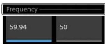
Buttons for related functions are grouped.
A line indicating the group name and range of the group is displayed above the buttons.
Depending on the function, only one button or multiple buttons within the group may be selected.
Tabs
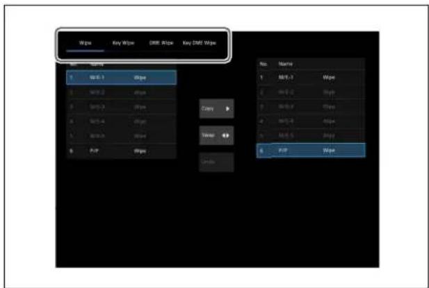
When the menu display area or a pop-up window comprises several pages, each page is displayed on a tab. Select a tab to change the display.
Selecting and Setting List Items
When the target of an operation is selectable from multiple items, the items are displayed in a list.

List display
You can move the display position in a list using a swipe operation or using the scrollbar slider in order to select a target item.
The row for the item that has focus is shown in light blue. When multiple items in a list can be selected, a checkbox is displayed on the left side of each item.
Selecting using a checkbox
To select an item, place a check mark in the checkbox. To select multiple items, place a check mark for the target items for operation.
'Select all' checkbox
To select or deselect all items, use the 'select all' checkbox.
When there are items selected in a list, a blue square is displayed in the 'select all' checkbox.
To select all items, place a check mark in the 'select all' checkbox.
To deselect all items, clear the check mark from the 'select all' checkbox.
Selecting by entering a list number
If a number selection button is displayed below the list, you can enter a list number to select an item.
Press the number selection button to display the numeric keypad window.
Enter the number of the target item and press [Enter].
When selecting multiple items, use a hyphen or comma to specify numbers.
Example:
To select list items 1 to 5, enter "1-5".
To select list items 1, 3, and 5, enter "1,3,5".
Button operations in a list
When setting items in a list, operation buttons may be displayed in the list depending on the menu.
In this manual, list item button operations use the following convention.
Example:
Operating a button in the [Tally Assign] row for an item in the list using the Home > Setup > Router/Tally > Tally > Parallel Tally menu (19106.26).
1 Open the Home > Setup > Router/Tally > Tally > Parallel Tally menu (19106.26).
2 Select the target parallel output port to set.
3 Press the [Tally Assign] button and select the type of tally from the pull-down list.
When there is only one target item
Selection of the item is not required.
In step 2 of the procedure above, check that the target item in the list is displayed on the menu screen. If the item is not displayed, move the display position in the list.
In subsequent procedure steps, you can configure settings by pressing buttons displayed in the row of the target item.
When there are multiple target items
In step 2 of the procedure above, place check marks in individual checkboxes or in the 'select all' checkbox to select target items.
Changes to the setting of one of the check marked items will apply the same change in setting to the other target items.
Changes to the setting of a parameter in the analog controls section are applied only to the item selected as the target, even if multiple items are selected. Also, you may not be able to change other settings simultaneously.
Setting Parameters
Pressing a parameter setting button displays an analog controls section on the right side of the menu display area for adjusting parameters.
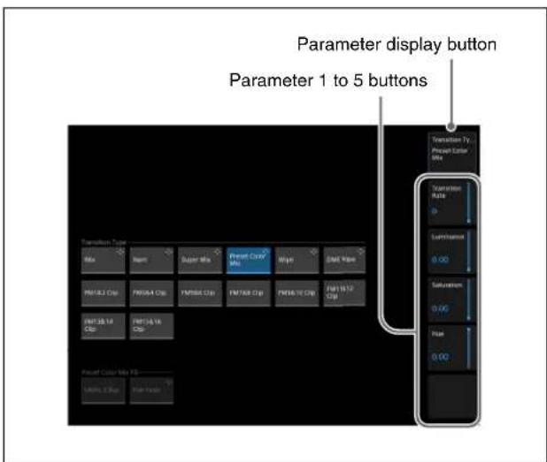
Analog controls section
This section is comprised by a parameter display button and up to five parameter buttons (numbered 1 to 5 from the top).
The target button name/group name to set is displayed on the parameter display button. If there are six or more parameters, a page number ("1/2" or "2/2") is displayed on the parameter display button, and pressing the button switches between page 1 and page 2.
The parameter name and current setting value are displayed on each of the parameter 1 to 5 buttons.
Pressing a parameter button displays an analog controls window for setting parameters.
In this manual, parameter setting operations are represented by the parameter button number and parameter name.
For parameters on two pages, the number is in "page number - parameter button number" format.
Example:
Parameters on one page only
| No. | Parameter Adjustment |
| 1 | Width Width |
| 2 | Position Position |
| 3 | Density Density |
Parameters on two pages
| No. | Parameter Adjustment |
| 1-1 | Top Position of top edge |
| 1-2 | Left Position of left edge |
| 1-3 | Right Position of right edge |
| 1-4 | Bottom Position of bottom edge |
| 2-1 | H Phase Horizontal position |
| 2-2 | V Phase Vertical position |
When using a mouse
You can click a parameter button and set the parameter using the following operations.
- Adjust the set value by moving the mouse wheel up/down.
- Adjust the set value by dragging the bar slider on the right side of the parameter button up/down.
Analog controls window
The analog controls window displays a numeric keypad on the left side and a parameter adjustment area on the right side.

A guide window is displayed at the same time as the analog controls window, which describes the operation method of the parameter adjustment area. To close the guide window, press [OK]. If you place a check mark in [Don't show this message again.], the guide window will not be displayed.
Note
You can display the guide window by pressing the guide display button.
When [Luminance], [Saturation], and [Hue] are all displayed in the analog controls section, you can switch between them and use the color palette window and analog controls window for adjustment.
Note
When [Resizer] > [Border] > [Beveled Color Edge] > [All] is selected in the Home > M/E-1 > Key1 > Resizer/Proc Key > Resizer Adjust/DME Select menu (11101.41), the color palette window is not displayed.

For details about operation in the color palette window, see "Color palette window" (page 82).
Entering parameters by touch operation
You can enter parameters in the parameter adjustment area.
The entered numeric value is displayed at the top center of the parameter adjustment area.
There are two types of parameter adjustment area, depending on the setting value.


Swipe operation type Touch operation type
Touch operation type
This type is displayed when the setting value is an integer with a narrow range of values.
Press the upper section (+) or lower section (−) to increment or decrement the numeric value by 1, respectively.
Swipe operation type
This type is displayed for all setting values other than touch operation type.
Swipe up/down to increase/decrease the numeric value. Swipe with two fingers to increase or decrease the numeric value quickly, and swipe with one finger to increase or decrease the numeric value slowly.
Using a mouse, press and hold the right button and then drag to increase a value or press and hold the left button and then drag to decrease a value.
Entering parameters using the numeric keypad
Enter a setting value for the parameter using the numeric keypad and press [Enter].
For details about numeric keypad operations, see
"Numeric keypad window" (page 73).
Note
Pressing [Enter] closes the analog controls window.
Returning parameters to the initial settings
Press the default recall button.
The parameters return to the initial status saved data setting values.
Color palette window
You can adjust the [Luminance], [Saturation], and [Hue] parameters using the color palette window.
Press the [Color Palette] tab to display the color palette window.
The color adjustment pane is displayed at the top, the preset color control block on the bottom left, and the custom color control block on the bottom right of the color palette window.

A guide window is displayed at the same time as the color palette window which describes the operation method of
the color palette window. To close the guide window, press [OK]. If you place a check mark in [Don't show this message again.], the guide window will not be displayed.
Note
You can display the guide window by pressing the guide display button.
①Color adjustment pane
Displays the target color to adjust as the current color together with the current color parameter values (Luminance, Saturation, Hue). You can create any color by adjusting each parameter using the color adjustment sliders or the [<] and [>] buttons.
If a parameter exceeds the RGB variable range (0 to 255), a warning message will be displayed and the parameter will be adjusted to be within the range.
②Preset color control block
The color palette displays up to 12 colors (preset colors) registered in the selected preset color types. You can select from five preset color types ([Color Bar], [Pastel], [Retro], [Macbeth 1], [Macbeth 2]) using the pull-down list to switch the color palette to display.
You can recall preset colors by pressing the color palette buttons.
③Custom color control block
The color palette displays up to 12 colors (custom colors) registered in the selected custom color palette. You can register the adjusted current color, registered preset colors, and custom colors registered in the same palette as custom colors in the color palette.
You can select from five custom color palettes ([User Palette 1], [User Palette 2], [User Palette 3], [User Palette 4], [User Palette 5]) using the pull-down list to switch the color palette to display.
You can rename custom color palettes.
For details about renaming a color palette, see "Renaming a custom color palette" (page 83).
A white diagonal line is displayed on color palette buttons without a registered color.
You can recall custom colors by pressing the color palette buttons.
Adjusting the color
1 Select the color to adjust in the preset color control block/custom color control block using one of the following methods.
- Press the color palette button to adjust.
- Drag and drop the color palette button to adjust to the current color in the color adjustment pane.
A light blue frame is displayed on the selected color palette button and any registered color palette buttons with the same color.
The target color to adjust is displayed as the current color in the color adjustment pane and the parameter values are reflected in the color adjustment sliders.
2 Adjust the color using the color adjustment sliders or the [<] and [>] buttons.
The [<] and [>] buttons support tap and long press operations.
Check the color while adjusting using the [Luminance], [Saturation], and [Hue] sliders.
Luminance: Luminance
Saturation: Saturation
Hue: Hue
After adjustment, a light blue frame is displayed around the current color.
Registering a color in a custom color palette
You can register a color in a custom color palette using one of the following methods.
- Drag and drop the current color from the color adjustment pane to a color palette button in the custom color control block.
- Drag and drop a registered color palette button from the preset color control block to a color palette button in the custom color control block.
When you drag & drop a color onto a color palette button in the custom color control block, a thick white frame is displayed around color palette buttons for which you can register a color.
Copying a custom color
Drag & drop a registered color palette button to the copy destination in the custom color control block.
Notes
- If a color is already registered at the drop position, it will be overwritten.
- An execution confirmation message appears when overwriting. To close the message, press [OK]. If you place a check mark in [Don't show this message again.], the execution confirmation message will not be displayed. Note that there is no setting available to return the confirmation message to the visible state. To make the message visible again, you must either recreate the user account, or delete the user account and reset the settings to their initial state.
Renaming a custom color palette
1 Click the [Rename] button.
The [Rename Color Palette Name] window appears.
2 Press the target color palette name to edit and enter a name.
3 Press [OK].
To cancel editing, press [Cancel].
Deleting a custom color
Drag & drop the color palette button for the custom color you want to delete to the deletion area.
The deletion area is displayed when you start dragging. When you drag & drop a color palette button into the deletion area, a thick white frame is displayed around the outer edge of the deletion area to indicate that you are within the area where it can be deleted. The deletion area is not displayed unless dragging a custom color.
Notes
- Multiple custom colors cannot be selected and deleted.
- An execution confirmation message appears when deleting. To close the message, press [OK]. If you place a check mark in [Don't show this message again.], the execution confirmation message will not be displayed. Note that there is no setting available to return the confirmation message to the visible state. To make the message visible again, you must either recreate the user account, or delete the user account and reset the settings to their initial state.
About color adjustment in the analog controls window
You can also adjust the [Luminance], [Saturation], and [Hue] parameters in the analog controls window. You can press [Analog Control] to display the analog controls window.

For details about the analog controls window, see "Analog controls window" (page 81).
Entering parameters using the key control block
Press the [MENU] button in the key control block to switch to menu parameter operation mode.
You can set parameters of the currently displayed menu using the adjustment knobs.
Adjustment knobs 1 to 5 correspond to the parameter 1 to 5 buttons. Adjust parameters by turning the adjustment knobs clockwise or counterclockwise.
Note
The control panel must be linked with the menu.
For details, see "Linking a Control Panel with the Menu" (page 87).
Entering parameters using the utility control block
Press the [MENU] button in the utility control block to switch to menu parameter operation mode.
You can set parameters of the currently displayed menu using the adjustment knobs.
Adjustment knobs 1 to 5 correspond to the parameter 1 to 5 buttons. Adjust parameters by turning the adjustment knobs clockwise or counterclockwise.
Note
The control panel must be linked with the menu.
For details, see “Linking a Control Panel with the Menu” (page 87).
Setting parameters using the device control block
Press the [MENU] button in the device control block to switch to menu parameter operation mode.
You can set parameters of the currently displayed menu using the trackball and Z-ring.
- The trackball X-axis direction corresponds to the parameter 1 button. Adjust the parameter by moving the trackball left/right.
- The trackball Y-axis direction corresponds to the parameter 2 button. Adjust the parameter by moving the trackball up/down.
- The Z-ring corresponds to the parameter 3 button. Adjust the parameter by turning the Z-ring clockwise or counterclockwise.
- Press the [FINE] button to switch to fine mode, enabling fine adjustment of setting values using the trackball and Z-ring.
Note
The control panel must be linked with the menu.
For details, see “Linking a Control Panel with the Menu” (page 87).
Initializing Settings (Default Recall)
You can return a menu to the initial status saved data setting value if a default recall button is displayed.
Notes
- You can initialize parameter setting values using a default recall button in the analog controls window. For details, see “Returning parameters to the initial settings” (page 82).
- You can initialize key setting values using buttons in the key control block. For details, see "Initializing Key Settings" (page 147).
- You can initialize switcher bank and two-dimensional transform (resizer) setting values using buttons in the device control block. For details, see “Reducing, enlarging, moving, and rotating keys (device control block)” (page 148).
- You can initialize three-dimensional transform (DME) setting values using buttons in the device control block or the menu. For details, see “Three-Dimensional Transform Operations (Device Control Block)” (page 209) and “Three-Dimensional Transform Operations (Menu)” (page 212).

1 Press the [Default Recall] button. 2 Check the message, then press [OK].
The menus below the selected level 3 menu return to their initial settings.
Note
In the case where a level 3 menu does not exist, the menus below the level 2 menu return to their initial settings.
Default recall target menus
• Home > M/E-x > Keyx menus • Home > M/E-x Sub > Keyx menus • Home > P/P > Keyx menus - Home > P/P Sub > Keyx menus (M/E-x = M/E-1 to M/E-5, Keyx = Key1 to Key8) When default recall is executed, all the menus below the level 3 menu return to their initial settings. However, the settings in the following lower level menus are not affected by default recall. - Type > Type Select menu > [Video Process] button settings - Type > Type Select menu > [Key Source] group settings - Type > Chroma Adjust menu > [Sample Mark] button parameter settings - Type > Chroma Adjust menu > [Sample Mark] button on/off settings (turned off after default recall is executed) - Type > Signal Select menu settings - Transition > Transition Type menu settings • Transition > DME Wipe menu settings • Transition > 1ch Pattern menu settings • Transition > 2ch Pattern menu settings - SL Key menu settings • Key Snapshot menu settings
Switching Taskbars
You can switch between five types of taskbar to display in the taskbar area.

Press the taskbar selection button in the taskbar area and select a taskbar from the pull-down list.
The taskbar area switches to the selected taskbar display.
Types of taskbar
[Favorites] taskbar
Displays shortcuts for registered menus.
For details, see “Registering Menus as Favorites” (page 86).
[Effect Timeline Recall/Store] taskbar
Displays operation buttons for recalling/saving effect timeline registers and for executing an effect timeline.
[Effect Timeline Edit] taskbar
Displays operation buttons for creating and editing an effect timeline.
[Macro Edit] taskbar
Displays operation buttons for editing macros.
[Snapshot] taskbar
Displays operation buttons for recalling/saving snapshot registers.
Registering Menus as Favorites
You can register frequently used menus or other menus as "favorites."
A favorite menu can be recalled by pressing a shortcut button displayed in the [Favorites] taskbar.
Notes
- Up to 100 shortcut buttons can be registered in the [Favorites] taskbar.
- Shortcut buttons are displayed in the order they were registered from the left.

1 Display the target menu to register.
2 Press the taskbar selection button and select [Favorites] from the pull-down list.
The taskbar area switches to the [Favorites] taskbar display.
3 Press the register favorite button.
The currently displayed menu is registered as a favorite menu and a shortcut button is added to the [Favorites] taskbar.
To cancel a registered favorite menu
Display the target menu to cancel and press the register favorite button to set it to the off state.
To register using the menu number button
The register favorite button is also displayed in the numeric keypad window displayed when the menu number button in the header area is pressed.
You can register/cancel a favorite menu in the same way as with the register favorite button in the [Favorites] taskbar.
Linking a Control Panel with the Menu
You can set a menu to operate by linking it with an operation from a control panel.
Multiple MLS-X1 menu clients can be connected simultaneously, but only one MLS-X1 menu client can be linked to an operation from a control panel.
The following control panel operations are link targets.
- Setting a parameter in the key control block in menu parameter operation mode
- Setting a parameter in the utility control block in menu parameter operation mode
- Setting a parameter in the device control block in menu parameter operation mode
- Recalling a menu by double-pressing a control panel button
- Menu shortcut functions of the memory recall buttons in the utility/shotbox control block, memory recall buttons in the utility control block, and cross-point buttons in the cross-point control block
- Memory recall section bank selection in the Flexi Pad control block in snapshot operation mode

1 Press the panel link button in the header area.
The connected control panel and the link icon are displayed on the panel link button.
2 Check the message, then press [OK].
The control panel link is set and the link icon turns light blue.
Note
If a control panel link is set while the control panel is linked to another menu client, the other menu link is canceled.
Also, once you set a control panel link, it cannot be canceled until another menu client is linked to the same control panel.
Entering and Displaying Text/Numbers
Press a numeric keypad input button to display the numeric keypad window and enter a numeric value.
For details, see "Numeric keypad window" (page 73).
Press a keyboard input button and enter alphanumeric characters using a computer keyboard/on-screen keyboard/touch panel.
Note
When entering text in a pop-up window, single-byte space characters are displayed as follows.
- If an entry begins with a single or multiple single-byte space characters, no space characters will be displayed.
- If an entry contains consecutive single-byte space characters, only a single space character will be displayed.
- If an entry contains a line break, it will be displayed as a single-byte space character. If you use a keyboard input button to enter text directly using a keyboard, single-byte space characters will be displayed as you enter them.
Invalid characters for names
The following characters cannot be used for entering content and folder names.
/: *? ^ lt; gt; |
In addition to the above, the following characters cannot be used in the names of package archive files saved in MLS Manager and in the names of system configuration files in MLS Manager:
Consecutive periods
Trailing period (except in file name extensions)
Note
When entering names shown on control panel buttons and the display, "|" is used as a line break code.
Name settings when multiple items are selected
When setting a name with multiple items selected, the same name may be set or a consecutive number may be appended to the name depending on the menu.
In the following menus, a consecutive number is appended to the name.
- Home > Setup > System > Input > Input Adjust menu (19101.31)
- Home > Setup > System > Source > Edit Source Name menu (19101.71)
- Home > Setup > Xpt Assign > V/K Pair > Logical V/K Pair Assign menu (19102.21)
- Home > Setup > Xpt Assign > V/K Pair > Edit Logical V/K Pair Name menu (19102.22)
- Home > Setup > Panel > Module > Utility Function Assign menu (19104.22)
Example:
Setting the source name of signals
If three signals are selected as the target and you enter "CAM", the name of each signal will become "CAM1", "CAM2", and "CAM3".
Timecode input and frame number input
When entering a timecode, you can select either timecode input mode or frame number input mode.
Timecode input mode
Press [TC] in the numeric keypad window, turning it on, to select timecode input mode.
Enter a value in "hh:mm:ss:ff"
(hour:minute:second:frame) format. The ":" (colon) is inserted automatically.
Example:
To set 3 minutes, 7 seconds, and 15 frames, enter "30715".
Frame number input mode
When [TC] in the numeric keypad window is turned off, frame number input mode is selected.
Enter a value in "fff" (frame) format.
Entering a difference from a current value
You can enter a value representing the increase or decrease from a currently set value to change the setting value.
[Trim] in the numeric keypad window is used to enter a difference value.
Enter a positive value and press [Trim] to increase the setting value.
Enter a negative value and press [Trim] to decrease the setting value.
Abbreviated display of long names
When a file name is too long to be displayed in full on a button or in a list, “...” is appended to the name.
Maximum number of valid input characters
The maximum number of characters described in this document is the maximum number when using ASCII characters only.
If characters other than ASCII characters are used, the maximum number of characters that can be entered is reduced.
Selecting and Displaying Regions
The term “region” refers to blocks classified by specific functions.
In effect timelines and snapshots, you can select target regions to save/recall registers. You can also select multiple regions simultaneously.
Types of Regions
The regions are classified as follows.
- Switcher bank regions: M/E-1 to M/E-5, P/P, M/E-1 Sub to M/E-5 Sub, P/P Sub
- User regions: User 1 to User 8 • DME regions: DME 1 to DME 4 (including DME Global) • External device regions: Device 1 to Device 12, P-Bus, GPI, Macro, Router
Notes
- In an effect timeline, regions other than Router are the target.
- In a snapshot, regions other than Device 1 to Device 12, P-Bus, GPI, and Macro are the target.
User regions
You can optionally assign the following regions to User 1 to User 8.
The user regions shown in parentheses are the default assignments.
• Color Bkgd 1, Color Bkgd 2 (User 1) • Aux 1 to Aux 48 (User 2) • Clip Player 1 to Clip Player 4 (User 3) • Frame Memory 1 to Frame Memory 16 (User 4)
For details about assigning a user region, see “Setting a User Region” (page 414).
Reference regions
When multiple regions are selected, the reference region is the display target in the menu.
When a reference region is removed from the target, the reference region will be set according to the following order of priority.
M/E-1 > M/E-1 Sub > M/E-2 > M/E-2 Sub > M/E-3 > M/E-3 Sub > M/E-4 > M/E-4 Sub > M/E-5 > M/E-5 Sub > P/P > P/P Sub > User 1 > User 2 > User 3 > User 4 > User 5 > User 6 > User 7 > User 8 > DME 1 > DME 2 > DME 3 > DME 4 > Device 1 > Device 2 > Device 3 >
Device 4 > Device 5 > Device 6 > Device 7 > Device 8 >
Device 9 > Device 10 > Device 11 > Device 12 > P-Bus
GPI > Macro > Router
Selecting a Region
When selecting the target region in the menus for effect timelines and snapshots, the region selection window appears.
Notes
- The display of the region selection window varies depending on the menu.
- An effect timeline/snapshot region or other region can be selected using the numeric keypad control block. For details, see "Selecting a region" (page 265).

When separate pages are displayed for each type of region, select a tab to switch the display.
To select a region, press the target region selection button, turning it on. A blue bar is displayed across the bottom of the button.
To cancel a selection, press the target region selection button, turning it off.
To select all regions
You can press the [All Regions] button to select all regions configured beforehand at the same time.
If you press the [All Regions] button while none of the configured target regions are selected, then the target regions are selected at the same time and all other regions are deselected.
If you press the [All Regions] button while at least one of the configured target regions is selected, all regions are deselected.
For details about setting the regions selected simultaneously, see “Setting Regions Selected Simultaneously” (page 428).
Region display section
The region display section shows the region selection status.
- Selected region: White text • Deselected region: Gray text • Reference region: Highlighted display
Overview
You can select a signal using the cross-point button rows in the cross-point control block or AUX bus control block (AUX bus operation mode) of each switcher bank.
ICP-X7000 cross-point control block
The number of buttons in a button row varies depending on the modules used.
• MKS-X7017: 36 buttons • MKS-X7018: 28 buttons • MKS-X7019: 20 buttons
The illustration below shows a 36-button cross-point control block (key bus mode).
Note
When the button row operation mode is key/AUX bus delegation mode, the 1st row becomes a delegation button row.
For details, see "Operation Mode of a Button Row" (page 95).
![graph TD A["1st row"] --> B["M/E 1"] A --> C["M/E 2"] A --> D["M/E 3"] A --> E["P/P SHIFT"] F["2nd row"] --> G["M/E 1"] F --> H["M/E 2"] F --> I["M/E 3"] F --> J["P/P SHIFT"] K["Display"] --> L[" "] --> M[" "] --> N[" "] --> O[" "] --> P[" "] --> Q[" "] --> R[" "] --> S[" "] --> T[" "] --> U[" "] --…](/content/2026/06/1382172/images/7758ca5a4bb0d71f9f2c00ba4a9054262bd57c75edbe37002efae14cf4406334.jpg)
ICP-X1000 series cross-point control block
The number of buttons in a button row varies depending on the control panel used.
- ICP-X1224, ICP-X1124: 24 buttons
- ICP-X1216, ICP-X1116: 16 buttons
The illustration below shows a 24-button cross-point control block (key/AUX bus delegation mode).
Note
When the button row operation mode is key bus mode or free assign mode, the 1st row becomes a cross-point button row.
For details, see "Operation Mode of a Button Row" (page 95).

ICP-X7000 AUX bus control block (AUX bus operation mode)
The number of buttons in a button row varies depending on the modules used.
• MKS-X7017: 36 buttons • MKS-X7018: 28 buttons • MKS-X7019: 20 buttons
The illustration below shows a 36-button AUX bus control block (AUX bus operation mode).

Cross-point buttons
The button numbers are labeled on the cross-point buttons of the cross-point control block/AUX bus control block. Signals are assigned for each button number and you select signals by pressing the buttons.
For details about assigning signals, see “Creating a Cross-Point Assign Table” (page 407).
Box internal signals
Each box has the following as internal signals.
- Switcher bank output signals • DME monitor
- Frame memory
- Clip player • Color backgrounds
For details about selecting the internal signals of individual boxes using cross-point buttons, see “Setting a Bus” (page 470) and “Setting Re-Entry Signals” (page 424).
Shift button
A shift button is assigned to the rightmost button of each cross-point button row.
You use the shift button to switch between the button number in the shifted state and the button number in the unshifted state in the button row.
The shift button has two operation modes.
Hold mode: Mode where the shifted state is selected while the button is pressed
Lock mode: Mode where every time the button is pressed, it toggles between the shifted state and unshifted state. You can also disable the shift button function.
For details, see "Setting the Shift Button" (page 407).
Delegation button row shift button
In an AUX bus control block, the shift button in delegation button rows (1st row/2nd row) can also be used.
A shift button is assigned to the rightmost button and can be set to hold mode or lock mode.
For details, see "Setting the operation mode of the shift button" (page 435).
Note
The shift button cannot be used in a delegation button row (1st row) on a cross-point control block in key/AUX bus delegation mode.
Re-entry buttons
You can assign re-entry signals to the cross-point button rows of the cross-point control block/AUX bus control block for use as re-entry buttons.
Re-entry buttons are used to load an image created on one switcher bank as an input signal on another switcher bank.
For example, to load the image created on M/E-1 as background B on M/E-2, press the M/E-1 re-entry button in the cross-point button row for the background B bus on M/E-2.
Notes
- M/E-1 to M/E-3 and P/P re-entry signals are assigned to the cross-point buttons by default. To use M/E-4 and M/E-5 re-entry signals, they must first be assigned to the cross-point buttons. For details about assigning buttons, see "Creating a Cross-Point Assign Table" (page 407).
- You can assign re-entry signal selection buttons to the cross-point pad of a cross-point control block/AUX bus control block on the ICP-X7000.
For details about assigning buttons, see "Setting a Cross-Point Pad" (page 436).
Re-entry signal restrictions
- Up to four re-entry stages are supported.
- Selecting a re-entry signal within the same switcher bank is not supported.
- When the system signal format is 2160P, 1080P, 1080PsF, or 1080i, a signal delay may occur when using four stacked re-entry stages in a multiple-box configuration.
- When the system signal format is 720P, the following signal delay may occur in a multiple-box configuration.
- If you select re-entry across slots in the third stage, a delay in the signal will occur.
A re-entry across slots comprises the following types of re-entry.
- Re-entry between an M/E assigned to slot 1 (bank 1 or bank 2) and an M/E assigned to slot 4 (bank 3 or bank 4)
- Re-entry between M/Es assigned to different logical boxes
- Re-entry between an M/E assigned to slot 1 (bank 1 or bank 2) and an M/E assigned to slot 4 (bank 3 or bank 4) - Re-entry between M/Es assigned to different logical boxes
Example 1: The following assignment in the Home > Setup > Switcher > Config > M/E Assign menu (19103.11)
• M/E-1 on box with logical box ID of 1, bank 1
• M/E-2 on box with logical box ID of 1, bank 2
- P/P on box with logical box ID of 1, bank 3
Example 2: The following assignment in the Home > Setup > Switcher > Config > M/E Assign menu (19103.11)
• M/E-2 on box with logical box ID of 1, bank 1
• M/E-1 on box with logical box ID of 1, bank 2
• P/P on box with logical box ID of 2, bank 1
- M/E-2 on box with logical box ID of 1, bank 1 - M/E-1 on box with logical box ID of 1, bank 2 - P/P on box with logical box ID of 2, bank 1
When M/Es are assigned as described above, a delay in the signal will occur when M/E-2 program output is selected on M/E-1 background A or when M/E-1 program output is selected on P/P background A.
For details about switcher bank assignment, see "Setting a Switcher Bank" (page 410).
- Stacked reentry across four stages will cause a delay in the signal.
Extended re-entry
When extended re-entry is enabled, selection of re-entry signals within the same switcher bank becomes possible.
For details, see "Setting Extended Re-Entry" (page 413).
Selecting a Bus (Cross-Point Control Block)
The cross-point button rows in a cross-point control block are shared by multiple buses.
Buses are assigned to the cross-point button rows for use.
Operation Mode of a Button Row
The operation mode of button rows in a cross-point control block can be selected from the following three modes.
By default, they are set to key bus mode on the ICP-X7000 and to key/AUX bus delegation mode on the ICP-X1000 series.
For details about setting the operation mode, see "Setting a Button Row in a Cross-Point Control Block" (page 434).
Key bus mode
Uses the 1st row and 2nd row as cross-point button rows for the bus/utility function selected by the delegation buttons.
Uses the 3rd row as a cross-point button row for background A bus, and the 4th row for background B bus. You can assign the following buses to the 1st row and 2nd row.
Key 1 bus to key 8 bus, utility 1 bus/2 bus, DME external video bus, DME utility 1 bus/2 bus
Free assign mode
Uses the 1st row to 4th row as cross-point button rows for the bus/utility function selected by the delegation buttons.
Key/AUX bus delegation mode
Uses the 1st row as a delegation button row and the 2nd row as a cross-point button row for the bus/utility function selected by the 1st row buttons.
Uses the 3rd row as a cross-point button row for background A bus, and the 4th row for background B bus.
Notes
- You can also change the bus assignment using dual background bus mode and utility bus mode. For details, see “Dual background bus mode” (page 96) and “Utility bus mode” (page 97).
- You can also select a utility function when a utility/shotbox bank is assigned to a cross-point button row. For details, see “Utility Functions” (page 241).
Bus Types and Assignments
You can select buses using the delegation buttons for assignment to cross-point button rows.
The assignable buses and assignment operation are as follows.
Notes
- You can assign the delegation buttons to use in key bus mode and free assign mode to the cross-point pad/function button section. For details about assigning buttons in the cross-point pad, see “Setting a Cross-Point Pad” (page 436). For details about assigning buttons in the function button section, see “Assigning Control Panel Buttons” (page 428).
- In key/AUX bus delegation mode, you can assign delegation buttons to the 1st row. For details, see “Setting the key/AUX bus delegation mode button row” (page 434).
- When using an SL key, key bus operation is disabled. For details about SL keys, see “SL Key” (page 127).
| Bus Assignment operation | |
| Background A busa) b) | In key bus mode and key/AUX bus delegation mode, assigned to the 3rd row (fixed).In free assign mode, press delegation button [A], turning it on. |
| Background B busa) b) | In key bus mode and key/AUX bus delegation mode, assigned to the 4th row (fixed).In free assign mode, press delegation button [B], turning it on. |
| Key 1 bus to key 8 busb) | Press delegation buttons [KEY1] to [KEY8], turning them on.c)To assign to the 2nd row in key/AUX bus delegation mode, press the [KEY1] to [KEY8] buttons in the 1st row, turning them on. |
| Utility 1 busb)Utility 2 busb) | ICP-X7000: Press delegation buttons [UTL1] and [UTL2], turning them on.c)ICP-X1000 series: Press delegation buttons [UTIL1] and [UTIL2], turning them on.c)To assign to the 2nd row in key/AUX bus delegation mode, press the [UTIL1] and [UTIL2] buttons in the 1st row, turning them on. |
| DME external video busb) | Press delegation button [DME EXT], turning it on.c)To assign to the 2nd row in key/AUX bus delegation mode, press the [DME EXT] button in the 1st row, turning it on. |
| DME utility 1 busb)DME utility 2 busb) | ICP-X7000: Press delegation buttons [DME UTL1] and [DME UTL2], turning them on.c)ICP-X1000 series: Press delegation buttons [DME UTIL1] and [DME UTIL2], turning them on.c)To assign to the 2nd row in key/AUX bus delegation mode, press the [DME UTIL1] and [DME UTIL2] buttons in the 1st row, turning them on. |
| Edit preview bus • In free assign mode, press delegation button [EDIT PVW], turning it on.To assign to the 2nd row in key/AUX bus delegation mode, press the [EDIT PVW] button in the 1st row, turning it on. | |
| AUX1 bus to AUX48 bus • In free assign mode, press delegation buttons [AUX1] to [AUX48], turning them on.To assign to the 2nd row in key/AUX bus delegation mode, press the [AUX1] to [AUX48] buttons in the 1st row, turning them on. | |
| Bus Assignment operation | |
| Frame memory source 1 busFrame memory source 2 bus | In free assign mode, press delegation buttons [FMS1] and [FMS2], turning them on.To assign to the 2nd row in key/AUX bus delegation mode, press the [FMS1] and [FMS2] buttons in the 1st row, turning them on. |
| DME1 video bus to DME4 video bus | In free assign mode, press delegation buttons [DME1V] to [DME4V], turning them on.To assign to the 2nd row in key/AUX bus delegation mode, press the [DME1V] to [DME4V] buttons in the 1st row, turning them on. |
| DME1 key bus to DME4 key bus | In free assign mode, press delegation buttons [DME1K] to [DME4K], turning them on.To assign to the 2nd row in key/AUX bus delegation mode, press the [DME1K] to [DME4K] buttons in the 1st row, turning them on. |
a) Dual background bus mode can be selected. b) Can also be assigned in utility bus mode. c) Can be assigned to the 1st row and 2nd row in key bus mode, or to the 1st row to 4th row in free assign mode.
Dual background bus mode
You can select the background A bus (3rd row) shifted-state signal in the 1st row, and the background B bus (4th row) shifted-state signal in the 2nd row.
To set dual background bus mode, press the [DUAL BKGD BUS] button, turning it on.
Notes
- The [DUAL BKGD BUS] button must be assigned to the cross-point pad/function button section.
For details about assigning buttons in the cross-point pad, see “Setting a Cross-Point Pad” (page 436).
For details about assigning buttons in the function button section, see “Assigning Control Panel Buttons” (page 428).
- Dual background bus mode is not available in the following cases.
– In free assign mode - When dual M/E is set - When the switcher bank operation mode is DSK mode
Utility bus mode
The following buses can be assigned to the 1st row to 4th row while the [UTIL] button assigned to the cross-point pad/function button section of the cross-point control block is pressed.
While the [UTIL] button is pressed, the DME utility 1 bus and DME utility 2 bus delegation buttons are displayed in the cross-point pad/function button section, and you can switch the 2nd row assignment by pressing one of the buttons.
- 1st row: DME external video bus
- 2nd row: DME utility 1 bus or DME utility 2 bus
- 3rd row: Utility 1 bus • 4th row: Utility 2 bus
You can change the bus assignments of the 1st row to 4th row. The following bus assignments are supported.
• Background A bus, B bus
• Key 1 bus to key 8 bus
The [UTIL] button operation can be set to hold mode or lock mode.
For details, see “Setting Utility Bus Mode” (page 436) and “Setting the operation mode of the [UTIL] button in the cross-point control block” (page 445).
Notes
- Utility bus mode is not available in the following cases: – In key/AUX bus delegation mode
- In free assign mode
- When dual background bus mode is set
- If a key bus is assigned using the [UTIL] button, the key source signal cannot be selected.
Selecting a Bus (AUX Bus Control Block)
The cross-point button rows in an AUX bus control block (AUX bus operation mode) are shared by multiple buses. Buses are assigned to the cross-point button rows for use.
Operation Mode of a Button Row
The button rows in an AUX bus control block may have different operation modes depending on whether second delegation mode is enabled/disabled.
Second delegation mode is disabled by default. To enable, press the [2ND DELG] button, turning it on, in the cross-point pad.
When second delegation mode is enabled
The 1st row and 2nd row are used as delegation button rows. The bus to assign to the 3rd row is selected in the 1st row, and the bus to assign to the 4th row is selected in the 2nd row.
The 3rd row is used as a cross-point button row for the bus selected in the 1st row. The 4th row is used as a cross-point button row for the bus selected in the 2nd row.
When second delegation mode is disabled
The 1st row and 2nd row are used as delegation button rows. The bus in the unshifted state is selected in the 1st row, and the bus in the shifted state is selected in the 2nd row.
The 3rd row and 4th row are used as cross-point button rows for the bus selected in the 1st row/2nd row. The signal in the unshifted state is selected in the 3rd row, and the signal in the shifted state is selected in the 4th row.
Note
When second delegation is disabled, the 1st row and 3rd row shift buttons are set to hold mode (fixed). You can select the button number in the shifted state while pressing the shift button.
The 2nd row and 4th row are always in the shifted state, hence the shift buttons cannot be operated.
Bus Types and Assignments
You can select buses using the delegation buttons for assignment to the 3rd row/4th row cross-point button rows.
The assignable buses and assignment operation are as follows.
Notes
- You can assign delegation buttons to the 1st row/2nd row.
For details about assigning buttons, see "Setting a delegation button row" (page 435).
- When using an SL key, key bus operation is disabled.
For details about SL keys, see "SL Key" (page 127).
| Bus Assignment operation | |
| Key 1 fill bus to key 8 fill bus | Press the following buttons in the 1st row/2nd row, turning them on.[M/Ex KEY1 V] to [M/Ex KEY8 V] buttons (x = 1 to 5)[P/P KEY1 V] to [P/P KEY8 V] buttons |
| Key 1 source bus to key 8 source bus | Press the following buttons in the 1st row/2nd row, turning them on.[M/Ex KEY1 K] to [M/Ex KEY8 K] buttons (x = 1 to 5)[P/P KEY1 K] to [P/P KEY8 K] buttons |
| Utility 1 bus Utility 2 bus | Press the following buttons in the 1st row/2nd row, turning them on.[M/Ex UTIL1], [M/Ex UTIL2] buttons (x = 1 to 5)[P/P UTIL1], [P/P UTIL2] buttons |
| Utility 2 bus (sub)a) | Press the following buttons in the 1st row/2nd row, turning them on.[M/Ex SUB UTIL2] button (x = 1 to 5)[P/P SUB UTIL2] button |
| DME external video bus | Press the following buttons in the 1st row/2nd row, turning them on.[M/Ex DME EXT] button (x = 1 to 5)[P/P DME EXT] button |
| DME utility 1 bus DME utility 2 bus | Press the [DME UTIL1] and [DME UTIL2] buttons in the 1st row/2nd row, turning them on. |
| Edit preview bus Press the [EDIT PVW] button in the 1st row/2nd row, turning it on. | |
| AUX1 bus to AUX48 bus | Press the [AUX1] to [AUX48] buttons in the 1st row/2nd row, turning them on. |
| Frame memory source 1 bus Frame memory source 2 bus | Press the [FMS1] and [FMS2] buttons in the 1st row/2nd row, turning them on. |
| DME1 video bus to DME4 video bus | Press the [DME1V] to [DME4V] buttons in the 1st row/2nd row, turning them on. |
| Bus Assignment operation | |
| DME1 key bus to DME4 key bus | Press the [DME1K] to [DME4K] buttons in the 1st row/2nd row, turning them on. |
a) Selects the utility 2 bus on the sub side when in multi program 2 mode.
Selecting Signals
Assigning Signals
Signals input to the input connectors and signals generated within the switcher can be selected using the cross-point buttons.
Each button number has assigned to it a video signal and a key signal, forming a pair.
For details, see "Creating a Cross-Point Assign Table" (page 407).
Cross-Point Button Numbers
ICP-X7000 36-button cross-point control block/AUX bus control block
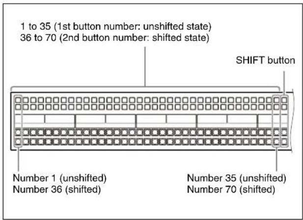
ICP-X1000 series 24-button cross-point control block

Cross-point control block
Each cross-point button has two button numbers, and you use the [SHIFT] button to switch between these numbers. In a 36-button row, the button numbers are as follows.
| Button Button numberwhen the [SHIFT]button is off | Button numberwhen the [SHIFT]button is on | |
| 1st (left side) to35th buttons | 1 to 35 36 to 70 |
In a 24-button row, the button numbers are as follows.
| Button Button numberwhen the [SHIFT]button is off | Button numberwhen the [SHIFT]button is on | |
| 1st (left side) to23rd buttons | 1 to 23 24 to 46 |
The rightmost (36th/24th) button is used as the [SHIFT] button.
When selecting the signal of button numbers 1 to 35/1 to 23, press the corresponding number button.
When selecting the signal of button numbers 36 to 70/24 to 46, press the [SHIFT] button, turning it on, and press the corresponding number button.
[SHIFT] button
The [SHIFT] button has two operation modes.
Hold mode: Mode where the shifted state is selected while the button is pressed
Lock mode: Mode where every time the button is pressed, it toggles between the shifted state and unshifted state. You can also disable the shift button function.
For details, see "Setting the Shift Button" (page 407).
Notes
- The operation mode of the [SHIFT] button is the operation mode set by the cross-point assign table of the switcher bank, regardless of the buses assigned to the cross-point button rows.
- The rightmost button operates as a cross-point button when the [SHIFT] button use is disabled. In a 36-button row, it becomes button number 36. In a 24-button row, it becomes button number 24.
[SHIFT ALL] button
You can switch all the cross-point buttons in the 1st row to 4th row to the shifted state using the [SHIFT ALL] button assigned to the cross-point pad/function button section (excluding 1st row delegation buttons in key/AUX bus delegation mode).
The [SHIFT ALL] button operation can be set to hold mode or lock mode.
Notes
- The [SHIFT ALL] button is enabled, even if the [SHIFT] button use is disabled.
The button numbers are as follows.
- 36-button row: 1 to 36 (unshifted state) to 37 to 72 (shifted state)
- 24-button row: 1 to 24 (unshifted state) to 25 to 48 (shifted state)
- The [SHIFT ALL] button is disabled in the following cases.
- In [SHIFT] button hold mode
- When dual background bus mode is set
- When dual M/E is set
AUX bus control block
Each cross-point button and delegation button has two button numbers, and you use the [SHIFT] button to switch between these numbers.
When second delegation mode is enabled
In a 36-button row, the button numbers are as follows.
| Button Button number when the [SHIFT] button is off | Button number when the [SHIFT] button is on |
| 1st (left side) to 35th buttons | 1 to 35 36 to 70 |
The rightmost (36th) button is used as the [SHIFT] button.
When selecting the bus/signal of button numbers 1 to 35, press the corresponding number button.
When selecting the bus/signal of button numbers 36 to 70, press the [SHIFT] button, turning it on, and press the corresponding number button.
When second delegation mode is disabled
In a 36-button row, the button numbers are as follows.
| Button Button number | when the [SHIFT] button is off | Button number when the [SHIFT] button is on |
| 1st row and 3rd row:1st (left side) to 35th buttons | 1 to 35 36 to 70 | |
| 2nd row and 4th row:1st (left side) to 35th buttons | -36 to 70 |
The rightmost (36th) button is used as the [SHIFT] button.
When selecting the bus/signal of button numbers 1 to 35 in the 1st row and 3rd row, press the corresponding number button.
When selecting the bus/signal of button numbers 36 to 70 in the 2nd row and 4th row, press the corresponding number button.
When selecting the bus/signal of button numbers 36 to 70 in the 1st row and 3rd row, press and hold the [SHIFT] button and press the corresponding number button.
[SHIFT] button
The [SHIFT] button has two operation modes.
Hold mode: Mode where the shifted state is selected while the button is pressed
Lock mode: Mode where every time the button is pressed, it toggles between the shifted state and unshifted state. In cross-point button rows (3rd row/4th row), you can also disable the shift button function.
For details about setting delegation button rows, see "Setting the operation mode of the shift button" (page 435).
For details about setting cross-point button rows, see "Setting the [SHIFT] button operation mode" (page 407).
Notes
- When second delegation is disabled, the 1st row and 3rd row shift buttons are set to hold mode (fixed). You can select the button number in the shifted state while pressing the shift button.
The 2nd row and 4th row are always in the shifted state, hence the shift buttons cannot be operated.
- The rightmost button operates as a cross-point button when the [SHIFT] button use is disabled in the cross-point button row.
In a 36-button row, it becomes button number 36.
Cross-Point Button Display
Names of signals
You can attach a name (logical V/K pair name or source name) to the signal assigned to a cross-point button, with a maximum of 16 characters.
The specified signal name appears on the display of the cross-point control block/AUX bus control block (AUX bus operation mode). When a signal in the shifted state of a cross-point button is selected, the name of the shifted-state signal is displayed.
Six types of display mode can be set according to the information to display. The display mode can be switched using the following buttons.
- ICP-X7000: Select display mode 1 to 6 using the display mode buttons assigned to the cross-point pad.
- ICP-X1000 series: The display mode switches each time the [DISP MODE] button assigned to the function button section is pressed.
For details about setting the signal name display, see "Setting Logical V/K Pair Names/Source Names and
Destination Names" (page 442) and "Setting a Logical V/K Pair" (page 405).
Colors of lit cross-point buttons
In a single cross-point button row, only the last pressed button is active, and is lit amber or red.
| Color of button when lit | Button state |
| Amber Low tally | Selected signal is not included in the final output image |
| Red High tally | Selected signal is included in the final output image |
Note
When second delegation mode is enabled on the AUX bus control block, 4th row cross-point buttons are lit green in the low tally state.
Cross-point indicators
When lit, these indicate the logical V/K pair color linked to the video signal logical V/K pair assigned to buttons on the 3rd row of the cross-point control block/AUX bus control block (AUX bus operation mode).
The color of the cross-point indicators does not change even if a 3rd row button is lit red or amber.
Cross-Point Hold
Setting cross-point hold enables you to recall an effect timeline or snapshot while keeping the current cross-point selection unchanged.
You can set cross-point hold for each cross-point button row.
To set cross-point hold, press the [XPT HOLD] button, turning it on, for the 1st row to 4th row assigned to the cross-point pad/function button section.
In a cross-point control block on the ICP-X7000, you can also set cross-point hold for each bus using the [XPTHLD XXX] button (where "XXX" is the bus name) assigned to the cross-point pad.
Note
When the switcher bank operation mode is set to multi program 2 mode, the following cross-point hold setting buttons function as buttons for the side (main or sub) selected by the [MAIN] button/[SUB] button. When both the [MAIN] button and [SUB] button are selected, settings are applied on both main and sub.
- [XPT HOLD] button: 1st row to 4th row cross-point hold (only when the background A bus, background B bus, or utility 2 bus is assigned to a button row)
- [XPTHLD A] button: Cross-point hold for the background A bus
- [XPTHLD B] button: Cross-point hold for the background B bus
- [XPTHLD UTL2] button: Cross-point hold for the utility 2 bus.
Key bus cross-point hold
For a key bus, the cross-point hold operation mode specified in the Home > Setup > Switcher > Custom > Key/Wipe menu (19103.43) is applied.
The following three operation modes can be set.
Key disable: Mode which maintains cross-point selection state and key settings information
Key disable (including key state): Mode which maintains cross-point selection state, key setting information, and the key inserted/removed (on/off) state
Cross-point hold: Mode which maintains cross-point selection state only
For details, see “Setting the Cross-Point Hold Operation Mode” (page 420).
Bus override
This function allows you to temporarily set cross-point hold for specific cross-point buttons only.
It is enabled for background A bus and background B bus cross-point buttons only.
When you press and hold a cross-point button and recall a snapshot, the cross-point selection state is maintained for the pressed button only. The cross-point selection state is maintained while the button is pressed, even when executing an effect timeline.
Selecting a Key Fill Signal/Key Source Signal
You can select a key fill signal and key source signal using the following methods.
To select a key fill signal
- Press a cross-point button in the e cross-point button row assigned with the key bus.
- In key bus mode and free assign mode, press and hold a key bus delegation button in the cross-point pad/function button section and press a cross-point button in the 1st row.
- In key/AUX bus delegation mode, press a key bus delegation button in the 1st row and press a cross-point button in the 2nd row.
- On the Flexi Pad control block in key operation mode, press and hold a key delegation button in the memory recall section and press a cross-point button in the 1st row in the cross-point control block.
- In key bus mode and free assign mode, press and hold the [SPLT] button in the key control block and press a
cross-point button in the 1st row of the cross-point control block.
- Press a cross-point button in the cross-point button row assigned with the key fill bus in the AUX bus control block (AUX bus operation mode).
To select a key source signal
- In key bus mode and free assign mode, press and hold a key bus delegation button in the cross-point pad/function button section and press a cross-point button in the 2nd row.
- In key/AUX bus delegation mode, press and hold a key bus delegation button in the 1st row and press a cross-point button in the 2nd row.
- On the Flexi Pad control block in key operation mode, press and hold a key delegation button in the memory recall section and press a cross-point button in the 2nd row in the cross-point control block.
- Press and hold the [SPLT] button in the key control block and press a cross-point button in the 2nd row of the cross-point control block.
- Press a cross-point button in the cross-point button row assigned with the key source bus in the AUX bus control block (AUX bus operation mode).
Notes
- You can also select a key fill signal/key source signal in the menu.
For details, see “Selecting the key fill/key source signals” (page 136).
- You can also select a signal paired with a key fill signal or select the key fill signal itself as the key source signal automatically.
For details, see “Setting a key fill/key source” (page 135) and “Setting a key fill/key source” (page 136).
- When the signal name of a key signal is displayed as the key source signal, the source name is always displayed on the panel.
Selecting a Video Signal/Key Signal
You can select the video signal or the key signal of a V/K pair using the [KEY] button assigned to the cross-point pad/function button section.
When a cross-point button is pressed while pressing the [KEY] button, the key signal is selected. When a cross-point button is pressed without pressing the [KEY] button, the video signal is selected.
Information for the key signal or video signal, whichever is selected, appears on the display on the cross-point control block/AUX bus control block (AUX bus operation mode).
Notes
- The [KEY] button cannot be used when a cross-point control block is set to key bus mode.
- The [KEY] button cannot be used on the following buses.
- Key fill bus (only the video signal is selectable) – DME video bus (only the video signal is selectable) – DME key bus (only the key signal is selectable)
- Background A bus, B bus (only the video signal is selectable)
- When the signal name of a key signal is displayed, the source name is always displayed on the panel.
For a key source signal
The [KEY] button is enabled in operation modes that allow you to select both a key signal and a video signal.
For details about settings, see “Setting the operation mode of the [KEY] button in the cross-point control block” (page 445).
When the [KEY] button is pressed, turning it on, and a cross-point button is pressed, the key signal is selected. When the [KEY] button is not lit and a cross-point button is pressed, the video signal is selected.
Note
For a key source signal, you can also select a video signal/key signal in the menu.
For details, see “Selecting the key fill/key source signals” (page 136).
Selecting a DME video signal/DME key signal
Press a cross-point button in the cross-point button row assigned with the DME video bus or DME key bus to select a signal.
When a cross-point button is pressed, the signal for the front side of the image is selected. When a cross-point button is pressed while pressing a DME video bus/DME key bus delegation button in a delegation button row, the signal for the back side of the image is selected.
Note
A signal for the back side can be selected when separate sides are enabled. When separate sides are disabled, the signals for the front and back sides are the same.
For details about setting separate sides, see “Setting Separate Sides” (page 221).
Preventing Operation of Cross-point Buttons
Preventing Operation of Cross-Point Buttons (Inhibit Function)
For each cross-point button in the cross-point control block, you can temporarily inhibit operations. To enable/disable the inhibit function, use the following buttons.
- ICP-X7000: [XPT INHBT SET] button and [XPT INHBT ALLCLR] button assigned to the cross-point pad
- ICP-X1000 series: [INHBT SET] button and [INHBT ALLCLR] button assigned to the function button section
When a cross-point button is set to inhibited, the operation of all cross-point buttons with the same number in the cross-point button rows are inhibited.
To inhibit a cross-point button
Press and hold the [XPT INHBT SET] button/[INHBT SET] button, and press the target cross-point button to set. While the [XPT INHBT SET] button/[INHBT SET] button is pressed, the inhibited buttons flash amber.
Notes
- When a cross-point button is inhibited, the button turns off and the display signal name is not displayed.
- Even when you inhibit a cross-point button, macro attachment settings are still possible.
- You can inhibit cross-point buttons for each cross-point assign table using the Home > Setup > Xpt Assign > Table Button Assign menu (19102.31). For details about setting inhibit mode, see “Creating Tables 1 to 14” (page 407).
To release the inhibit setting for a cross-point button
Press and hold the [XPT INHBT SET] button/[INHBT SET] button, and press the target cross-point button to release.
To release the inhibit setting for all cross-point buttons
Press and hold the [XPT INHBT SET] button/[INHBT SET] button, and press the [XPT INHBT ALLCLR] button/[INHBT ALLCLR] button.
Preventing Operation of a Cross-Point Button Row (Protect Function)
You can temporarily prevent button operations for each cross-point button row on the cross-point control block. To enable/disable the protect function, use the following buttons.
- ICP-X7000: [ROW-1 PROT] button to [ROW-4 PROT] button assigned to the cross-point pad
- ICP-X1000 series: [PROT] button in the 1st row to 4th row assigned to the function button section
To protect a cross-point button row
Press the [ROW-1 PROT] button to [ROW-4 PROT] button/[PROT] button, turning it on, for the target cross-point button row (1st row to 4th row) to set.
To release the protection setting for a cross-point button row
Press the [ROW-1 PROT] button to [ROW-4 PROT] button/[PROT] button, turning it off, for the target cross-point button row (1st row to 4th row) to release.
Transitions
Chapter
5
Overview
Switching from the current output image to a new image is referred to as a transition.
Switching a background image or key insertion/removal can be performed, depending on the transition.
The method for switching images (transition type) can be set, and the transition executed using the buttons and fader lever on the control panel.
Independent key transition
In addition to common transitions, it is possible to configure independent transitions for each key.
Executing an independent key transition in combination with a common transition enables different transition types to be used for the background and keys.
Transition operation flow![graph TD A["Select the current background"] --> B["Select a next transition (see page 106)"] B --> C["Background Key"] C --> D["Select a new background Set keys"] D --> E["Select and set a transition type (see page 109)"] E --> F["Preview transition (see page 118)"] F --> G["Execute transition (see…](/content/2026/06/1382172/images/6854f2c78e44b6f3dc2ee8fad5ea555e87773e1aad2095d9713d3c2cb566d457.jpg)
Changing the background
To switch the background in a transition, select a background for the next transition.
Select a background image using the background A bus and background B bus.
When set to flip-flop mode, background A is the existing image and background B is the new image. The
background always switches from background A to background B. When the transition completes, the cross-points of the background A bus and background B bus interchange.
In bus fixed mode, depending on the transition, the cross-points of the background A bus and background B bus do not interchange.
For details, see “Flip-flop mode and bus fixed mode” (page 114).
Inserting and removing a key
To insert/remove a key in a transition, select a key for the next transition.
When a key that is not inserted in the current background image is selected, depending on the transition, the key is inserted.
When a key that is inserted is selected, depending on the transition, the key is removed.
You can also simultaneously insert and remove keys when switching the background.
You can also change the key overlay sequence (key priority), depending on the transition.
Transition type
You can set the way in which the transition occurs.
You can select the following transition types.
| Transition type Description | |
| Mix The new image progressively fades in over the current image. The sum of the two image outputs is maintained constant, and the output of each is at 50% at the mid-point of the transition. | |
| NAM (non-additive mix) | The current image and new image are compared, and the image with the higher luminance level is given priority in the output. The output of each is at 100% at the mid-point of the transition. |
| Super mix The current image output is held at 100%, and is mixed with the new image. The output at the mid-point of the transition can be 0% to 100%. | |
| Preset color mix A color matte (plain image) is inserted during the transition, where the current image is switched to the new image in a two-stage transition. | |
| Wipe The current image switches to the new image using a wipe pattern. | |
| DME wipe The current image switches to the new image using a DME wipe pattern. | |
| Clip transition Plays back frame memory video content linked to a mix or wipe transition. | |
| Cut The current image switches instantaneously to the new image. | |
Basic Operation for Transitions
The basic transition operation flow is as follows.
1 Select a background image using the background A bus cross-point buttons in the cross-point control block.
2 Select the switch target of a transition.
Select a next transition using the next transition selection buttons in the transition control block.
For details about next transitions, see “Next Transitions” (page 106).
3 Set the state for after the transition executes.
When switching the background, select a background image using the background B bus cross-point buttons.
For details about selecting a signal, see “Chapter 4 Selecting Signals” (page 91).
When inserting a key, set the key to insert.
For details about setting keys, see “Chapter 6 Keys” (page 126).
When changing the key overlay sequence, set the key priority.
For details about key priority, see “Key Priority” (page 107).
4 Select a transition type.
Select a transition type using the transition type selection buttons in the transition control block. To switch (cut) from the current image instantaneously to the new image, proceed to step 6.
For details about transition types, see “Transition Type” (page 109).
5 Set the transition type.
Make the required settings for the selected transition type.
• Transition rate settings (see page 111) • Super mix settings (see page 110) • Preset color mix settings (see page 110) • Wipe settings (see page 159) • DME wipe settings (see page 175) • Clip transition settings (see page 183)
Using transition preview mode, you can check the execution of the transition.
For details about transition preview, see “Transition Preview” (page 118).
When a wipe or DME wipe is selected as the transition type, you can set the transition execution range (pattern limit).
For details about pattern limits, see “Pattern Limit” (page 116).
6 Execute a transition.
Execute the transition using the buttons and fader lever in the transition control block.
For details about executing transitions, see "Executing a Transition" (page 112).
Next Transitions
You can select the switch target of a transition. Next transitions are configured using the transition control block.
Note
In the simple-type transition control block, only background transition operations are supported. Next transition selection is not supported.
Selecting a Next Transition
You can select a next transition using the transition control block of the target switcher bank.
Note
The buttons used for configuring a next transition must be assigned to the transition control block beforehand.
For details about assigning buttons, see “Assigning Control Panel Buttons” (page 428).
Select the switch target of a transition using the next transition selection buttons. Multiple next transition selection buttons can be pressed and lit at the same time.
To switch the background
Press the [BKGD] button, turning it on. Select a background image for after the transition using the background B bus cross-point buttons.
For details about image selection, see “Chapter 4 Selecting Signals” (page 91).
To insert/remove a key
Press a [KEY1] to [KEY8] button, turning it on. If a key is not inserted, it will be inserted. If a key is inserted, it will be removed. When inserting a key, set the key to insert.
For details about setting keys, see “Chapter 6 Keys” (page 126).
To remove all inserted keys
Press the [BKGD] button twice.
Note
Double-pressing of the [BKGD] button must first be enabled.
For details about settings, see “Enabling double-press for the [BKGD] button in the transition control block” (page 444).
To change the key overlay sequence
Press the [KEY PRIOR] button.
Set the key priority for after the transition.
For details about key priority, see “Key Priority” (page 107).
To select multiple preconfigured next transitions simultaneously
Press the [ALL] button.
For details about setting next transitions selected simultaneously, see “Setting the next transitions to select using the [ALL] button in the transition control block” (page 444).
Key Priority
When multiple keys are inserted, you can set the overlay sequence of the keys.
When the [KEY PRIOR] button is selected in a next transition, depending on the transition, the key overlay sequence changes.
The key overlay sequence is set by key priority values 1 to 8, numbered from the front to the rear.
The key priority can be set using the transition control block or the menu.
Notes
- In the simple-type transition control block, key priority cannot be configured.
- When the operation mode of the switcher bank is set to multi program mode or multi program 2 mode, the key priority cannot be changed, depending on the transition.
- The key priority cannot be configured in fixed mode. For details, see “Setting the Key Priority Mode” (page 419).
- The current key overlay sequence can be checked on the program output of the switcher bank. When the [KEY PRIOR] button is selected in a next transition, the key overlay sequence for after the transition can be checked on the preview output of the switcher bank.
Key priority of SL keys
SL keys 5 to 8 are assigned the priority of four keys as a single group.
Within SL keys 5 to 8, you can set any priority.
Example:
Overlay keys in the sequence key 1, key 2, SL keys 5 to 8, key 3, key 4
Set the priority as follows.
Priority 1: Key 1
Priority 2: Key 2
Priority 3 to 6: SL keys 5 to 8 (priority 3 to 6 can be assigned arbitrarily within SL keys 5 to 8)
Priority 7: Key 3
Priority 8: Key 4
Note
When the system signal format is 2160P, the SL key function must be enabled for use.
For details about settings, see "Setting a GPU" (page 384).
Setting Key Priority
Setting the key priority (transition control block)
You can set the key priority using the transition control block of the target switcher bank.
Note
The buttons used for configuring the key priority must be assigned to the transition control block beforehand.
For details about assigning buttons, see “Assigning Control Panel Buttons” (page 428).
1 Press and hold the [PRIOR SET] and press the [KEY PRIOR] button to select the target key priority (current key priority or key priority for after the transition) to set.
When the [KEY PRIOR] button is lit green, the key priority setting for after the transition is selected. When the [KEY PRIOR] button is not lit, the current key priority setting is selected.
2 Set the key to display at the front.
Press and hold the [PRIOR SET] button and press a [KEY1] to [KEY8] button.
The selected key is set to be frontmost (priority 1). To set the key priority for after the transition to the same setting as the current setting, press and hold the [PRIOR SET] button and press the [BKGD] button.
Note
The [BKGD] button is enabled only when in the mode for changing the key priority for after the transition.
3 Repeat steps 1 and 2 to set the key priority, as required.
Setting the key priority (menu)
This section describes the M/E-1 menu as an example.
1 Open the Home > M/E-1 > Common > Key Priority/Key Assign menu (11110.11). 2 Select the target key priority (current key priority or key priority for after the transition) to set.
When setting the current key priority
Press the [Edit] button for [Current Key Priority]. The [Current Key Priority] window appears.
When setting the key priority for after the transition
Press the [Edit] button for [Next Key Priority]. The [Next Key Priority] window appears.
3 Set the buttons for the keys to set to priority 1 to 8 to the on state in [Priority 1] to [Priority 8].
Note
The priority options available for selection vary depending on the number of keys assigned to a switcher bank.
4 Press [OK].
Checking the key priority settings
The key on/off status and priority status are shown on the display of the transition control block.
Note
In the transition control block of the ICP-X1000 series, the key on/off status and priority status are shown only while setting the key priority (while the [PRIOR SET] button is pressed).
Key on/off status display
When a key is inserted, [K1] to [K8] are displayed highlighted.
Key priority display
The numbers 1 to 8 (priority 1 to 8) are displayed under the on/off status indicators for each key.
If the [KEY PRIOR] button is selected, the priority (1 to 8) of keys for after the transition are displayed highlighted on the right of the current priority. The key priority for after the transition is not displayed if the values are the same as the current priority setting.
Note
In the transition control block of the ICP-X7000, only the priority status for after the transition is shown while setting the key priority for after the transition.
Transition Type
You can set the way in which the transition occurs. The transition type is configured using the transition control block, simple-type transition type control block, or the menu.
For details about transition types, see “Transition type” (page 105).
Setting a Transition Type
Setting a transition type (transition control block)
You can select a transition type using the transition control block/transition control block (simple type) of the target switcher bank.
Notes
- The buttons used for configuring the transition type must be assigned to the transition control block/transition control block (simple type) beforehand. For details about assigning buttons, see “Assigning Control Panel Buttons” (page 428).
- When the operation mode of the switcher bank is set to multi program mode or multi program 2 mode, preset color mix cannot be used when selecting a key for a next transition.
- When the operation mode of the switcher bank is set to multi program mode or multi program 2 mode, there may be cases in which two or more transition type selection buttons are lit.
1 Select a transition type using the transition type selection buttons.
Press the [MIX] button, [NAM] button, [SUPER MIX] button, [PST COLOR MIX] button, [WIPE] button, [DME WIPE] button, or a [FM1&2 CLIP] to [FM15&16 CLIP] button, turning it on.
2 Set the transition type.
Make the required settings for the selected transition type.
When a mix, non-additive mix, super mix, preset color mix, wipe, or DME wipe is selected Set the transition rate.
For details about the transition rate, see “Transition Rate” (page 111).
When super mix is selected
Set the output level at the mid-point of the transition.
For details, see "Setting Super Mix" (page 110).
When preset color mix is selected
Set the color matte to insert during the transition.
For details, see "Setting a Preset Color Mix" (page 110).
When a wipe is selected
Set the wipe pattern.
For details, see "Setting a Wipe" (page 159).
When a DME wipe is selected
Set the DME wipe pattern.
For details, see "Setting a DME Wipe" (page 175).
When a clip transition is selected
Set the clip transition.
For details, see "Setting a Clip Transition" (page 183).
Setting the key transition type (menu)
This section describes the M/E-1 menu as an example.
1 Open the Home > M/E-1 > Bus/Transition > Transition > Transition Type menu (11109.21).
2 Select a transition type in the [Transition Type] group.
Mix: Mix
NAM: Non-additive mix
Super Mix: Super mix
Preset Color Mix: Preset color mix
Wipe: Wipe
DME Wipe: DME wipe
FM 1&2 Clip to FM 15&16 Clip: Clip transition
3 Set the transition type.
Make the required settings for the selected transition type.
When a mix, non-additive mix, super mix, preset color mix, wipe, or DME wipe is selected Set the transition rate.
For details about the transition rate, see “Transition Rate” (page 111).
When super mix is selected
Set the output level at the mid-point of the transition.
For details, see "Setting Super Mix" (page 110).
When preset color mix is selected
Set the color matte to insert during the transition.
For details, see "Setting a Preset Color Mix" (page 110).
When a wipe is selected
Set the wipe pattern.
For details, see "Setting a Wipe" (page 159).
When a DME wipe is selected
Set the DME wipe pattern.
For details, see "Setting a DME Wipe" (page 175).
When a clip transition is selected
Set the clip transition.
For details, see "Setting a Clip Transition" (page 183).
Setting Super Mix
Set the output levels of the current image and new image at the mid-point of the transition. You can set a value in the range 0% to 100%.
This section describes the M/E-1 menu as an example.
1 Open the Home > M/E-1 > Bus/Transition > Transition > Transition Type menu (11109.21).
2 Set the [Super Mix] button in the [Transition Type] group to the on state and set the following parameters.
| No. | Parameter Adjustment | |
| 2 | A Gain Background A | output level |
| 3 | B Gain Background B | output level |
Setting a Preset Color Mix
Set the color matte to insert in a preset color mix.
You can also use the utility 2 bus signal in place of a color matte.
This section describes the M/E-1 menu as an example.
Preset color mix mode
You can set the following modes in a preset color mix.
For details, see “Setting the Preset Color Mix Mode” (page 418).
Stroke mode:
In a preset color mix, the current image switches to the color matte on the 1st stroke, and then switches from the color matte to the new image on the 2nd stroke (normal mode).
You can also set a preset color mix so that it executes in one stroke (single mode).
Note
In bus fixed mode, single mode is selected.
One-time mode:
Return to the previous transition type when the preset color mix transition is completed.
Non-drop key:
If a key is inserted in the current image, it is removed by the color matte during the transition, and the key status for after the transition is applied to the new image. You can set a mode that the selected key is not removed by the color matte.
1 Open the Home > M/E-1 > Bus/Transition > Transition > Transition Type menu (11109.21).
2 Set the [Preset Color Mix] button in the [Transition Type] group to the on state.
3 Select an image to insert in the [Preset Color Mix Fill] group.
Utility 2 Bus: Utility 2 bus signal
For details about selecting a signal, see “Chapter 4 Selecting Signals” (page 91).
Flat Color: Color matte
When the [Flat Color] button is selected, set the following parameters.
| No. | Parameter Adjustment |
| 2 | Luminance Luminance |
| 3 | Saturation Saturation |
| 4 | Hue |
Transition Rate
You can set the time taken from the beginning of a transition to its completion.
The transition rate is configured using the Flexi Pad control block, utility/shotbox control block and numeric keypad control block, or the menu.
Note
When a clip transition is selected as the transition type, it is not possible to set the transition rate.
Transition Rate Input/Display Mode
Transition rate input mode
When entering the transition rate, you can select either frame number input or timecode input.
For details, see “Timecode input and frame number input” (page 88).
Frame number input:
Enter a number in the range 0 to 999 frames.
Timecode input:
Enter a value converted to frames of up to 999 frames.
Transition rate display mode
You can set the transition rate display mode to frame number display or timecode display.
The display mode settings are common to all switcher banks.
For details, see “Setting the transition rate display” (page 443).
Frame number display:
Displays the number of frames (0 to 999). Values entered in timecode input mode are converted to the number of frames for display.
Timecode display:
Displays a “ss:ff” timecode value (second:frame). Values entered in frame input mode are converted to a timecode for display.
Setting the Transition Rate
You can set the speed at which a transition switches from the current image to a new image (time taken from the beginning of a transition to its completion).
In an auto transition, the transition is executed automatically with the preset transition rate.
Setting the transition rate (Flexi Pad control block)
You can set the transition rate using the Flexi Pad control block of the target switcher bank.
1 Press the [TRANS RATE] button.
The memory recall section switches to transition rate operation mode.
2 Enter a transition rate using the number input buttons.
You can switch the input mode using the [TC] button. In frame number input mode, enter three digits. In timecode input mode, enter four digits.
The entered value appears in the top right button of the memory recall section.
To delete the entered value
Press the [CLEAR] button.
3 Press the [ENTER] button.
Setting the transition rate (utility/shotbox control block and numeric keypad control block)
When the utility/shotbox control block is switched to transition rate display mode, the transition rate is displayed in the memory recall section. Press a memory recall button to select a transition rate, and set it using the numeric keypad control block.
Note
You can change the transition rate display mode transition rate assignments.
For details, see “Setting Transition Rate Display Mode Buttons” (page 431).
1 Press the [TRANS RATE1] button to [TRANS RATE3] button in the utility/shotbox control block.
The memory recall section switches to transition rate display mode.
2 Press the memory recall button displaying the target transition rate to set, turning it on.
The target region name and transition rate to set are shown on the display of the numeric keypad control block.
3 Enter a transition rate using the numeric keypad of the numeric keypad control block.
You can switch the input mode using the [TC] button.
In frame number input mode, enter three digits. In timecode input mode, enter four digits.
To delete the entered value
Press the [CLR] button.
Note
You can also enter a difference value from the currently set value using the [TRIM] button.
For details, see “Entering a difference from a current value” (page 88).
4 Press the [ENTER] button.
The entry is applied and the set value is reflected on the memory recall button in the utility/shotbox control block.
Setting the transition rate (menu)
This section describes the M/E-1 menu as an example.
1 Open the Home > M/E-1 > Bus/Transition > Transition > Transition Type menu (11109.21). 2 Select a transition type in the [Transition Type] group. 3 Set the transition rate using the following parameter.
| No. | Parameter Adjustment |
| 1 | Transition Rate Transition rate |
To set the transition rate in list view
You can set the transition rate in transition rate list view on each switcher bank.
1 Open the Home > Utility > Transition Rate menu (18201.21).
The transition rate for common transitions and independent key transitions is displayed for each switcher bank.
2 Select the target switcher bank to set. 3 Press the [Common] button and enter a transition rate in the numeric keypad window.
In multi program 2 mode, enter a transition rate for main using the [Common] button, and a transition rate for sub using the [Sub Common] button.
Executing a Transition
Transitions are executed using the transition control block or simple-type transition control block.
You can also execute auto transitions using the menu.
Note
In the simple-type transition control block, only background transition operations are supported. The buttons used for executing a transition must be assigned to the transition control block (simple type) beforehand.
For details about assigning buttons, see “Assigning Control Panel Buttons” (page 428).
ICP-X7000 transition control block
ICP-X7000 transition control block (simple type)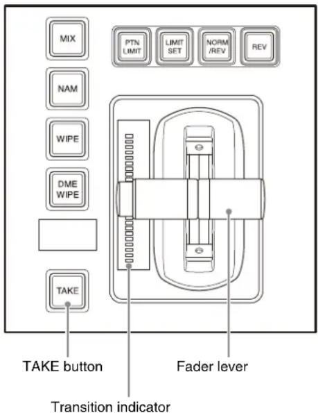
ICP-X1000 series transition control block
There are two modes for carrying out a transition: auto transitions are carried out by a button operation, and manual transitions are carried out using the fader lever. It is also possible to combine both methods, taking control with the fader lever of an auto transition which has partly completed, or completing a transition started with the fader lever as an auto transition.
Transition indicator
You can check the transition execution status using the transition indicator on the transition control block/ transition control block (simple type).
The transition indicator displays the transition execution status by which LEDs are lit and which are not, both for manual transitions and auto transitions.
When the transition indicator is lit up to the center point, the transition progress has reached 50%.
When the transition is completed, the transition indicator turns off.
Auto Transitions
To switch images with the preset transition type and transition rate
Press the [AUTO TRANS] button in the transition control block or the [TAKE] button in the transition control block (simple type).
The transition is executed automatically with the preset speed (transition rate).
During the transition execution, the [AUTO TRANS] button/[TAKE] button is lit amber.
To switch images instantaneously
Press the [CUT] button in the transition control block/transition control block (simple type).
When the next transition is a key, the key is inserted or removed instantaneously.
To complete a partially executed transition instantaneously
Press the [CUT] button in the transition control block/transition control block (simple type).
The [AUTO TRANS] button/[TAKE] button turns off.
Changing from auto transition to manual transition
During a transition started by pressing the [AUTO TRANS] button/[TAKE] button, operating the fader lever immediately enables the fader lever, and the [AUTO TRANS] button/[TAKE] button turns off. Thereafter, the fader lever controls the execution of the transition.
Executing an auto transition using the menu
This section describes the M/E-1 menu as an example.
1 Open the Home > M/E-1 > Bus/Transition > Wipe > Wipe Snapshot menu (11109.37) or Home > M/E-1 > Bus/Transition > DME Wipe > DME Wipe Snapshot menu (11109.46).

Press the [AUTO TRANS] button.
Manual Transitions (Fader Lever)
You can switch from the current image to the new image using the fader lever on the transition control block/transition control block (simple type).
This executes a transition with the set transition type.
To execute the transition completely
Move the fader lever over the full range of its travel.
To pause a partly executed transition
Stop moving the fader lever.
To resume a paused transition
Resume moving the fader lever.
Changing from manual transition to auto transition
Stop fader lever operation and press the [CUT] button to instantaneously complete the transition.
Stop the fader lever operation and press the [AUTO TRANS] button/[TAKE] button to complete the execution of the rest of the transition with the preset transition rate. For example, if the transition rate is set to 100 frames, and the fader lever has moved through 1/4 of the transition, then the remaining 3/4 of the transition is executed in 100 frames.
Fader Lever Operation
Non-sync
If the fader lever is stopped in an intermediate position and an auto transition is executed, then the fader lever position will not match the current position of the transition when the transition is completed. This is termed non-sync state.
You can check for non-sync state by whether the top and bottom LEDs of the transition indicator are lit or flashing.
For details about LED light/flashing settings, see "Setting the transition indicator display in non-sync state" (page 444).
Non-sync state and LED display
- If a non-sync state occurs after moving the fader lever from top to bottom, the top two LEDs light/flash.
- If a non-sync state occurs after moving the fader lever from bottom to top, the bottom two LEDs light/flash.
- Moving the fader lever toward the position of the lit/flashing LEDs does not execute a transition. When the fader lever reaches the end position, the non-sync state is released and the LEDs turn off.
- If the fader lever is moved in the direction away from the lit/flashing LEDs, a 100% transition is executed over the remaining part of the fader lever travel and the LEDs turn off.
- Even in non-sync state, you can execute an auto transition. During auto transition execution, the transition indicator shows the transition progress in the usual way, but when the transition completes, the indicator once again indicates non-sync state.
Flip-flop mode and bus fixed mode
Cross-points can be switched by a transition in flip-flop mode and bus fixed mode.
For details about setting flip-flop mode/bus fixed mode, see “Setting Flip-Flop Mode” (page 417).
![graph TD A["Lit buttons"] --> B["Fader lever"] B --> C["Flip-flop mode"] C --> D["Bus fixed mode"]](/content/2026/06/1382172/images/2a55db2340c3dacf4a834ddc2661a322ebd468bab5febaab775b35aab241f33e.jpg)
Flip-flop mode
The signal selected on the background A bus is the current image, and the signal selected on the background B bus is the new image. The background always switches from background A to background B. When the transition completes, the cross-points of the background A bus and background B bus interchange.
Bus fixed mode
Depending on the transition, the cross-points of the background A bus and background B bus do not interchange.
When the fader lever is at the top of its travel, the background A bus signal is 100% output. When the fader lever is at the bottom of its travel, background B bus signal is 100% output.
To execute a manual transition, operate the fader lever in the direction of the transition as shown below.
Auto transitions are executed regardless of the fader lever position.
| Next transition Transition direction | Fader lever movement | |
| Background | A → B | Top → Bottom |
| B → A | Bottom → Top | |
| Key 1 to key 8 On → Of f (remove) | Top → Bottom | |
| Off → On (insert) B bottom → Top | ||
Notes
- When the background and one or more keys (1 to 8) are targets of a transition, the transition direction of all selected background/keys must be the same as the fader lever operation direction.
- If as a result of an auto transition, the fader lever position does not match the background/key signal output state, a non-sync state occurs and LEDs light/flash at both ends of the transition indicator.
Split fader
Split fader is a function that splits a single fader lever into left and right, allowing you to control background A bus and background B bus transitions independently.
The fader lever on the simple-type transition control block is split into two by pressing the lock button to unlock the two fader levers for use as split faders.
The split fader levers support the following buses.
- Right fader lever: Background A bus (main)
- Left fader lever: Background B bus
The split fader function can be enabled/disabled for each switcher bank. You can also change which is the main fader lever.
For details about setting split fader, see “Enabling/Disabling Split Faders” (page 418) and “Setting the main fader lever when using split faders” (page 445).
The following conditions must be satisfied in order to use the fader lever as split faders.
- Bus fixed mode is set.
- Split faders are enabled.
- Mix or NAM (non-additive mix) is selected for transition type.
- If the transition type is a clip transition, Mix or NAM (non-additive mix) is selected for the background transition type.
- If the switcher bank operation mode is set to multi program 2 mode, the switcher bank is set to main. If these conditions are not satisfied, only the main (background A bus) fader lever can be operated.
Note
When not using split fader lever operation, disable split faders.
If enabled, a black image or super mix image may be output when the transition type is changed.
Split fader operation
The relationship between the position of the fader lever and the output for a mix transition type is given below.
| Fader lever position Output | |||
| Right lever (A bus) | Left lever (B bus) | A bus B bus | |
| Top Top 100% | 0% | ||
| Top Bottom 100% | 100% | ||
| Bottom Top 0% | 0% | ||
| Bottom Bottom 0% | 100% | ||
| Center Center | 50% 50% | ||
The A bus and B bus output for a NAM transition type is an image created using non-additive mixing.
Note
The transition indicator displays the progress of the background A bus.
Pattern Limit
When a wipe or DME wipe is selected as the transition type, you can specify the transition execution limit. When the pattern limit function is enabled, the following transitions occur, depending on the execution limit settings.
- When the execution limit is set to 50%, the result at the completion of the transition is the same as if the fader lever is at the center position with the pattern limit function disabled.
- When the execution limit is set to the minimum of 0%, the image is not switched even when the transition is executed.
- When the execution limit is set to the maximum of 100%, the image changes in the same way as if the pattern limit function is disabled, but when the transition is completed, the cross-points on the background A bus and B bus do not interchange.
The pattern limit is configured using the transition control block, simple-type transition type control block, or the menu.
Notes
- When the operation mode of the switcher bank is set to multi program mode, pattern limits can be set only when the background transition type is a wipe or DME wipe. If a key is selected for a next transition, the pattern limit settings are reflected in the wipe or DME wipe selected for the background transition type.
- The buttons used for configuring and executing pattern limits must be assigned to the transition control block/transition control block (simple type) beforehand. For details about assigning buttons, see “Assigning Control Panel Buttons” (page 428).
To set a pattern limit while checking a transition preview
Press the [TRANS PVW] button, turning it on, in the transition control block.
You can adjust the pattern limit while checking the transition status on a monitor set with the preview output.
For details, see "Transition Preview" (page 118).
Setting a Pattern Limit
Setting a pattern limit (transition control block)
You can set a pattern limit using the transition control block/transition control block (simple type) of the target switcher bank.
Note
Check that the [PTN LIMIT] button is off.
1 Move the fader lever to the position corresponding to the desired pattern size.
2 Press the [LIMIT SET] button.
This sets the current fader lever position as the pattern limit.
Setting a pattern limit (menu)
This section describes the M/E-1 menu as an example.
1 Open the pattern limit setting menu.
When the transition type is a wipe, open the Home > M/E-1 > Bus/Transition > Wipe > Pattern Mix/Edge/Direction menu (11109.33).
When the transition type is a DME wipe, open the Home > M/E-1 > Bus/Transition > DME Wipe > Edge/Direction menu (11109.44).
2 Set the [Pattern Limit] button to the on state and set the following parameter.
| No. | Parameter Adjustment |
| 1 | Pattern Limit Pattern limit range (0.00% to 100.00%) |
Executing a Pattern Limit
1 Press the [PTN LIMIT] button, turning it on, in the transition control block/transition control block (simple type).
The [PTN LIMIT] button is lit amber.
2 Execute a transition.
The transition progresses as far as the set pattern limit.
3 Execute the transition once again.
The state existing before executing the transition is restored.
Releasing a pattern limit
When the state existing before executing the transition is restored by performing step 3, press the [PTN LIMIT] button to release a pattern limit, turning the [PTN LIMIT] button off.
To release a pattern limit in pattern limit state, execute a transition using the following procedure.
You can set the operation mode for executing a transition when releasing a pattern limit to manual or auto.
For details about setting the operation mode, see “Setting the Operation Mode When the Pattern Limit is Released” (page 420).
1 Press the [PTN LIMIT] button in the transition control block/transition control block (simple type). The [PTN LIMIT] button is lit green.
2 Execute a transition.
If the operation mode when a pattern limit is released is set to auto
Press the [PTN LIMIT] button to execute the remainder of the transition automatically with the preset transition rate. When the transition is completed, the pattern limit is released and the [PTN LIMIT] button turns off.
If the operation mode when a pattern limit is released is set to manual
Execute the remainder of the transition using one of the following methods. When the transition is completed, the [PTN LIMIT] button turns off.
- Press the [CUT] button. The image switches instantaneously and the pattern limit is released.
- Press the [AUTO TRANS] button/[TAKE] button. The remainder of the transition is executed with the preset transition rate and the pattern limit is released when execution is completed.
- Operate the fader lever. If the fader lever is moved in the execution direction of the transition, the remainder of the transition is executed and the pattern limit is released when execution is completed. If the fader lever is moved in the opposite direction, the transition is executed such that the state before executing the transition is restored, and the pattern limit is released when execution is completed.
To set the transition rate when the pattern limit is released
This section describes the M/E-1 menu as an example.
1 Open the pattern limit setting menu.
When the transition type is a wipe, open the Home > M/E-1 > Bus/Transition > Wipe > Pattern Mix/Edge/Direction menu (11109.33).
When the transition type is a DME wipe, open the Home > M/E-1 > Bus/Transition > DME Wipe > Edge/Direction menu (11109.44).
2 Set the transition rate in the [Pattern Limit Release] group.
Auto Trans Rate: Follow the current transition rate. Independ Trans Rate: Set an independent transition rate for releasing a pattern limit.
When the [Independ Trans Rate] button is selected, set the following parameter.
| No. | Parameter Adjustment |
| 1 | Transition Rate Transition rate when the pattern limit is released |
Transition Preview
In transition preview mode, the status during a transition is output on the preview output of the switcher bank.
You can check the change in the image due to a transition in advance using a monitor configured for the preview output.
Notes
- In the simple-type transition control block, transition preview cannot be configured or executed.
- It is not possible to execute a transition preview in the following cases.
- Transition in progress
- When bus fixed mode is set
- When the switcher bank operation mode is not standard mode
- The buttons used for configuring and executing a transition preview must be assigned to the transition control block beforehand. For details about assigning buttons, see “Assigning Control Panel Buttons” (page 428).
Setting Transition Preview
There are two modes for a transition preview.
Normal:
Set the [TRANS PVW] button operation mode to hold mode or lock mode. In hold mode, the transition preview mode is enabled only while the [TRANS PVW] button is pressed. In lock mode, pressing the [TRANS PVW] button switches between setting and releasing transition preview mode each time the button is pressed.
For details about setting lock mode/hold mode, see "Setting the operation mode of the [TRANS PVW] button in the transition control block" (page 444).
One-time:
Pressing the [TRANS PVW] button switches to transition preview mode, and then transition preview mode is released when the transition is completed.
For details about setting normal mode/one-time mode,
see "Setting the Transition Preview Mode" (page 417).
Executing Transition Preview
1 Press the [TRANS PVW] button, turning it on, in the transition control block.
The [TRANS PVW] button is lit green, and the switcher enters transition preview mode. The current program output is displayed on the preview output monitor.
2 Execute a transition.
The status during the transition is displayed on the preview output monitor allowing you to check the changes to the image.
Independent Key Transitions
Overview
In addition to common transitions, you can configure independent transitions for each key.
When an operation mode that supports configuration of transitions where keys are inserted/removed independently is set, the transition type and transition rate for inserting and removing keys can be set separately.
For details about independent key transition operation mode, see “Setting the Independent Key Transition Mode” (page 417).
Transition type of independent key transitions
You can set an independent key transition to the following transition types.
- Mix
- Wipe • DME wipe
- Cut
For details about transition types, see “Transition type” (page 105).
Common transitions and independent key transitions
Executing an independent key transition in combination with a common transition enables different transition types to be used for the background and keys.
You can also set a common transition and an independent key transition for the same key.
If an auto transition is executed with both a common transition and independent key transition configured, the following occurs depending on the start timing of the transitions.
When the common transition and independent key transition are executed simultaneously
If a key is inserted:
The key is removed simultaneously in both transition types. When the common transition ends, both transitions are completed even if the independent key transition is in progress.
If a key is not inserted:
The key is inserted simultaneously in both transition types. The transitions are completed at the point when both the common transition and independent key transition have ended.
When the common transition and independent key transition are executed at offset times
If a key is inserted:
The key is removed in both transition types at offset times. When the common transition ends, both transitions are completed even if the independent key transition is in progress.
If a key is not inserted:
The key is inserted in the transition of the first executed transition type. Subsequently, the key is then inserted, so that when the transition with the other transition type is executed the key will be removed. The transition is completed at the point when the key is removed.
Basic Independent Key Transition Operations
The basic independent key transition operation flow is as follows.
1 Select a transition type for the independent key transition.
For details about transition types, see “Setting the Independent Key Transition Type” (page 119).
2 Set the transition type.
Make the required settings for the selected transition type.
• Transition rate settings (see page 121) - Wipe settings (see page 168) • DME wipe settings (see page 180)
Using transition preview mode, you can check the status of the transition.
For details about transition preview, see “Transition Preview” (page 118).
3 Execute the independent key transition.
For details about executing transitions, see
"Executing an Independent Key Transition" (page 122).
Setting the Independent Key Transition Type
You can set the way in which the independent key transition occurs.
The independent key transition type is configured using the Flexi Pad control block, key fader control block, or the menu.
Note
When an operation mode that supports configuration of transitions where keys are inserted/removed independently is set, the transition type for inserting and removing keys can be set separately.
For details about independent key transition operation mode, see “Setting the Independent Key Transition Mode” (page 417).
Setting the independent key transition type (Flexi Pad control block)
You can set the independent key transition type using the Flexi Pad control block of the target switcher bank.
1 Press the [KEY] button.
The memory recall section switches to key operation mode.
2 Select the target key to set.
Press a [KEY1] to [KEY8] button, turning it on.
3 Select a transition type.
Press the [MIX] button, [WIPE] button, or [DME WIPE] button, turning it on.
In operation modes that support configuration of transitions separately for when keys are inserted/removed, configuration while a key is not inserted sets the transition type for key insertion and configuration while a key is inserted sets the transition type for key removal.
4 Set the transition type.
Make the required settings for the selected transition type.
When a mix, wipe, or DME wipe is selected. Set the transition rate.
For details about the transition rate, see “Setting the Independent Key Transition Rate” (page 121).
When a wipe is selected
Set the wipe pattern.
For details, see “Setting an Independent Key Transition Wipe” (page 168).
When a DME wipe is selected
Set the DME wipe pattern.
For details, see “Setting an Independent Key Transition DME Wipe” (page 180).
Setting the independent key transition type (key fader control block)
You can set the independent key transition type for a key assigned to a key delegation button.
For details about assigning key delegation buttons, see "Assigning Control Panel Buttons" (page 428).
1 Select the target key to set.
Press a key delegation button, turning it on.
2 Select a transition type.
Press the [MIX] button, [WIPE] button, [DME WIPE] button, or [CUT] button, turning it on.
In operation modes that support configuration of transitions separately for when keys are inserted/removed, configuration while a key is not inserted sets the transition type for key insertion and configuration while a key is inserted sets the transition type for key removal.
When you press and hold the [SHIFT] button and press the independent key transition type selection button, you can set the transition type for key removal while a key is not inserted and the transition type for key insertion while a key is inserted.
3 Set the transition type.
Make the required settings for the selected transition type.
When a mix, wipe, or DME wipe is selected. Set the transition rate.
For details about the transition rate, see “Setting the Independent Key Transition Rate” (page 121).
When a wipe is selected
Set the wipe pattern.
For details, see “Setting an Independent Key Transition Wipe” (page 168).
When a DME wipe is selected Set the DME wipe pattern.
For details, see “Setting an Independent Key Transition DME Wipe” (page 180).
Setting the independent key transition type (menu)
This section describes the M/E-1 key 1 menu as an example.
1 Open the Home > M/E-1 > Key1 > Transition > Transition Type menu (11101.51).
2 Select a transition type in the [Transition Type] group.
Mix: Mix
Wipe: Wipe
DME Wipe: DME wipe
Cut: Cut
When an operation mode that supports configuration of transitions where keys are inserted/removed independently is set, select a transition type for key insertion in the [ON Transition Type] group and a transition type for key removal in the [OFF Transition Type] group.
3 Set the transition type.
Make the required settings for the selected transition type.
When a mix, wipe, or DME wipe is selected
Set the transition rate.
For details about the transition rate, see “Setting the Independent Key Transition Rate” (page 121).
When a wipe is selected
Set the wipe pattern.
For details, see “Setting an Independent Key Transition Wipe” (page 168).
When a DME wipe is selected
Set the DME wipe pattern.
For details, see “Setting an Independent Key Transition DME Wipe” (page 180).
Checking the independent key transition type setting
On the ICP-X7000, you can check the transition type on the display in the independent key transition execution section of the transition control block, display in the independent key transition control block, or display in the key fader control block.
The transition type is indicated by the letters “M” (mix), “W” (wipe), “D” (DME wipe), and “C” (cut).
Note
When the transition rate is set to timecode display, the transition type is not displayed.
Setting the Independent Key Transition Rate
You can set the time taken from the beginning of an independent key transition to its completion.
The independent key transition rate is configured using the utility/shotbox control block and numeric keypad control block, or the menu.
Note
When an operation mode that supports configuration of transitions where keys are inserted/removed independently is set, the transition rate for inserting and removing keys can be set separately.
For details about independent key transition operation mode, see “Setting the Independent Key Transition Mode” (page 417).
Setting the independent key transition rate (utility/shotbox control block and numeric keypad control block)
When the utility/shotbox control block is switched to transition rate display mode, the transition rate is displayed in the memory recall section. Press a memory recall button to select a transition rate, and set it using the numeric keypad control block.
Note
You can change the transition rate display mode transition rate assignments.
For details, see “Setting Transition Rate Display Mode Buttons” (page 431).
1 Press the [TRANS RATE1] button to [TRANS RATE3] button in the utility/shotbox control block.
The memory recall section switches to transition rate display mode.
2 Press the memory recall button displaying the transition rate of the target key to set, turning it on.
The target region name and transition rate to set are shown on the display of the numeric keypad control block.
In operation modes that support configuration of transitions separately for when keys are inserted/removed, configuration while a key is not inserted sets the transition rate for key insertion and configuration while a key is inserted sets the transition rate for key removal.
3 Enter a transition rate using the numeric keypad of the numeric keypad control block.
You can switch the input mode using the [TC] button. In frame number input mode, enter three digits. In timecode input mode, enter four digits.
To delete the entered value
Press the [CLR] button.
Note
You can also enter a difference value from the currently set value using the [TRIM] button.
For details, see “Entering a difference from a current value” (page 88).
4 Press the [ENTER] button.
The entry is applied and the set value is reflected on the memory recall button in the utility/shotbox control block.
Setting the independent key transition rate (menu)
This section describes the M/E-1 key 1 menu as an example.
1 Open the Home > M/E-1 > Key1 > Transition > Transition Type menu (11101.51).
2 Select a transition type in the [Transition Type] group.
When an operation mode that supports configuration of transitions where keys are inserted/removed independently is set, select a transition type for key insertion in the [ON Transition Type] group and a transition type for key removal in the [OFF Transition Type] group.
3 Set the transition rate using the following parameter.
| No. | Parameter Adjustment |
| 1 | Transition Rate Transition rate |
Note
When a cut is selected as the transition type, it is not possible to set the transition rate.
To set the transition rate in list view
You can set the transition rate in transition rate list view on each switcher bank.
1 Open the Home > Utility > Transition Rate menu (18201.21).
The transition rate for common transitions and independent key transitions is displayed for each switcher bank.
2 Select the target switcher bank to set.
3 Press the [Edit] button.
The transition rate setup window appears.
4 Press a [Key1] to [Key8] button and enter a transition rate in the numeric keypad window.
When an operation mode that supports configuration of transitions where keys are inserted/removed independently is set, select a transition type for key insertion using a [Key1] to [Key8] button in [Key On] and a transition type for key removal using a [Key1] to [Key8] button in [Key Off].
5 Press [OK].
Checking the independent key transition rate setting
On the ICP-X7000, you can check the transition rate on the display in the independent key transition execution section of the transition control block, display in the independent key transition control block, or display in the key fader control block.
Executing an Independent Key Transition
An independent key transition can be executed using the transition control block, independent key transition control block, key fader control block, or the menu.
Notes
- In the simple-type transition control block, an independent key transition cannot be executed.
- In an independent key transition, the pattern limit function is not available.
Executing an independent key transition (transition control block)
ICP-X7000 transition control block
ICP-X1000 series transition control block
Independent key transition execution section
Note
The buttons used for executing an independent key transition must be assigned to the transition control block beforehand.
For details about assigning buttons, see “Assigning Control Panel Buttons” (page 428).
To insert/remove a key instantaneously
Press a [KEY1 ON] to [KEY8 ON] button.
To insert/remove a key with the preset transition type and transition rate
Press the following buttons.
- ICP-X7000: [AUTO TRANS] button for the corresponding key
- ICP-X1000 series: [KEY1 TRANS] button to [KEY8 TRANS] button
During the transition execution, the button is lit amber and goes off when the transition is completed.
Notes
- You can change this so that during the execution of the transition, the button is lit green and when the transition is completed it is lit red if on-air or lit amber if not on-air. For details about settings, see “Setting the independent key transition, auto transition execution button display” (page 443).
- When a cut is selected as the transition type, the key is inserted/removed instantaneously.
Executing an independent key transition (independent key transition control block)
Note
The buttons used for executing an independent key transition must be assigned to the independent key transition control block beforehand.
For details about assigning buttons, see “Assigning Control Panel Buttons” (page 428).
To insert/remove a key instantaneously
Press a [KEY1 ON] to [KEY8 ON] button.
To insert/remove a key with the preset transition type and transition rate
Press the [AUTO TRANS] button for the corresponding key.
During the transition execution, the button is lit amber and goes off when the transition is completed.
Notes
- You can change this so that during the execution of the transition, the button is lit green and when the transition is completed it is lit red if on-air or lit amber if not on-air. For details about settings, see “Setting the independent key transition, auto transition execution button display” (page 443).
- When a cut is selected as the transition type, the key is inserted/removed instantaneously.
Executing an independent key transition (key fader control block)
You can execute an independent key transition for a key assigned to a key delegation button.
For details about assigning key delegation buttons, see "Assigning Control Panel Buttons" (page 428).
To insert/remove a key instantaneously
Press the [KEY ON] button.
Note
The [KEY ON] button label indicates the key assigned to the key delegation button.
To insert/remove a key with the preset transition type and transition rate
Press the [AUTO TRANS] button for the corresponding key.
During the transition execution, the button is lit amber and goes off when the transition is completed.
Notes
- You can change this so that during the execution of the transition, the button is lit green and when the transition is completed it is lit red if on-air or lit amber if not on-air. For details about settings, see “Setting the independent key transition, auto transition execution button display” (page 443).
- When a cut is selected as the transition type, the key is inserted/removed instantaneously.
To insert/remove a key manually with the preset transition type
Operate using the fader lever.
Note
You can set the key which is the target of fader lever operation.
For details about setting the fader lever, see “Assigning Control Panel Buttons” (page 428).
Executing an independent key transition (menu)
This section describes the M/E-1 key 1 menu as an example.
1 Open the Home > M/E-1 > Key1 > Key Snapshot menu (11101.71).
2 Execute a transition.
To insert/remove a key instantaneously
Press the [KEY ON] button.
To insert/remove a key with the preset transition type and transition rate
Press the [KEY TRANS] button.
Note
When a cut is selected as the transition type, the key is inserted/removed instantaneously.
Fade-to-Black
This function gradually darkens the image and changes the P/P program output image to black.
Note
When the switcher bank operation mode is multi-program mode, multi program 2 mode, or DSK mode, fade-to-black is executed for multiple program outputs simultaneously.
You can also disable fade-to-black for each program output.
For details, see “Enabling/Disabling Fade-To-Black” (page 418).
Setting Fade-to-Black
Assigning a utility command
To execute fade-to-black, the "Fade To Black" utility command must be assigned to the following buttons beforehand.
- Memory recall buttons in the utility/shotbox control block
- Memory recall buttons in the utility control block • Cross-point buttons in the cross-point control block
For details about assigning a utility command, see "Assigning a utility command" (page 431).
Setting the transition rate
1 Open the Home > P/P > Bus/Transition > Transition > Transition Type menu (11909.21). 2 Press the [FTB] button and enter a transition rate in the numeric keypad window.
To set the transition rate in list view
You can set the fade-to-black transition rate in transition rate list view on each switcher bank.
1 Open the Home > Utility > Transition Rate menu (18201.21). 2 Press the [FTB] button and enter a transition rate in the numeric keypad window.
Executing Fade-to-Black
This section describes operation using a memory recall button ([FTB] button) in the utility/shotbox control block or utility control block assigned with the "Fade To Black" utility command.
1 Select a bank.
For details about selecting a bank in the utility/shotbox control block, see "Selecting a bank" (page 243).
In the utility control block, press the [UTIL/SBOX] button to switch the memory recall section to utility/shotbox operation mode and select a bank.
For details about selecting a bank in the utility control block, see "Selecting a bank" (page 244).
2 Press the [FTB] button.
This executes fade-to-black with the preset transition rate.
During the transition execution, the [FTB] button is lit light purple.
When the transition is completed, the image becomes black and the [FTB] button color changes to red.
Overview
A key is a function in which a part of the background image is replaced by inserting an image or superimposed text.
The signal used to cut out a portion of the background image (key source), signal to embed in the cutout portion (key fill), and key source processing method (key type) can be selected for a key.
The number of keys that can be used on each switcher bank is six when the system signal format is 2160P, and eight when the system signal format is 1080P, 1080PsF, 1080i, or 720P.
Notes
- When M/E split is enabled, the number of keys that can be used will vary depending on the settings.
- When the system signal format is 2160P, two of the six keys available for each switcher bank are restricted keys. These keys are called “additional keys.”
For details, see "Setting sub block full keys" (page 410).
Key Fill and Key Source
The key fill signal can be set to a key bus signal or color matte.
The key source signal can be selected using the following three modes.
Self mode: Use the same signal as the key fill signal.
Auto Select mode: Use the signal assigned as a pair with the key fill bus signal on the cross-points.
Split mode: Select and use a different signal than the key fill bus pair signal.
Key Type
The key type sets the manner in which the key source is used to cut out the background.
You can select the following key types.
| Key type Description | |
| Luminance key The | the background is cut out according to the luminance signal of the key source, and at the same time the key fill is also cut out by the key source and then added to the background. |
| Linear key This is | a type of luminance key, with a reduced variability in gain allowing more precise adjustment. |
| Chroma key A key | signal based on a particular color is used to cut out the background, and the key fill is then inserted. |
| Key wipe pattern key | A wipe pattern of an independent key transition is used to cut out the background, and the key fill is then inserted. |
Clean mode
In a luminance key or linear key, you can enable clean mode.
When clean mode is enabled, key fill is added to the background without cutting out by the key source.
Note
When clean mode is enabled, for the parts of the key fill that are not black (excluding the part that is inserted), color is added to the background.
Key Modifiers
Edge type
Adds borders and other modifiers to the edge to a key.
| Edge type Description | |
| Normal State with | no modifiers added. |
| Border Adds a border around the key.You can adjust the border width and density. | |
| Drop border Adds | a border to the bottom and right edges of the key.You can adjust the border width, position, and density. |
| Shadow Adds a shadow to the bottom and right edges of the key.You can adjust the shadow width, position, and density. | |
| Outline Adds the outline to the key.You can adjust the outline width and density. | |
| Emboss Adds an embossing effect around the key.You can adjust the emboss width, position, and density. | |
Edge fill
A signal inserted in the edge areas is called an edge fill. In a border, drop border, or shadow, a color matte or a signal selected on the utility 1 bus can be set as the edge fill.
Notes
- In an outline, the key fill signal selected by the key fills the outline, and the background signal fills the rest of the image.
- In an emboss, color matte 1 signal and color matte 2 signal are used for the embossing.
Key drop
You can lower the key fill/key source position.
Key drop on mode: The key fill/key source position moves downward by eight lines or four lines.
In key drop on mode for a drop border or shadow, it is possible to add a border to the top edge of the key.
Key drop off mode: The key fill/key source position does not move.
Frame delay mode
When frame delay mode is enabled, key drop is set to key drop off mode (fixed).
Zabton
Inserts a translucent pattern to the key background. You can adjust the pattern size, color, and other parameters.
Mask
A mask is a function that allows a part of the image to be replaced by the background or a key. You can correct an image, such as unwanted holes that appear in the background or when a key is not the desired shape, using masks.
Two masks (main mask and sub mask) can be used on each key.
There are two types of masks.
Key mask: This masks out a part of the key so that the background becomes visible.
Background mask: This masks out a part of the background so that the key fill becomes visible.
Key Memory
This function allows the key settings data on each cross-point button to be automatically stored, so that when the same cross-point button number is selected the settings data are recalled.
There are two adjustment modes, depending on the settings data being stored.
Simple mode: Key type, clean mode (including chroma key plane function), key position, key invert, key adjustments (excluding color cancel, window, Y balance, shadow, foreground color correction of a chroma key) settings are stored.
Full mode: All settings, excluding transitions, are stored.
For details about setting key memory mode, see “Setting the Key Memory Mode” (page 419).
Resizer
A resizer is used to set a two-dimensional transform (move, enlarge/reduce, rotate) or border/crop on a key. It can also add effects to a key.
Note
A resizer cannot be used on additional keys.
SL Key
An SL key is a software key that uses a GPU to reproduce the same functions as a hardware key.
If the number of keys on a single switcher bank is four or lower, SL keys are set as key 5 to key 8.
Only one switcher bank can use an SL key.
In an SL key, there are restrictions on the functions and settings that can be used.
For details about setting SL keys, see “Setting an SL key” (page 410).
For details about SL key restrictions, see “SL Key Restrictions” (page 563).
To use the SL key function, the MZS-X1620 SL Key License (option) is required.
When the system signal format is 2160P, the SL key function must be enabled for use.
For details about setting GPU functions, see “Setting a GPU” (page 384).
Key fill/key source for SL keys
Still image combined content is used as the key fill/key source for SL keys.
When content is selected as a key fill/key source for an SL key, the content must be loaded into the SL key work area using the key 5 to key 8 menus.
The number of content resources that can be loaded into the SL key work area is given below.
| System signal format Number | ber of content resources |
| 2160P 20 | |
| 1080P 80 | |
| 1080PsF 80 | |
| 1080i 80 | |
| 720P 180 |
Key Type
The key type sets the manner in which the key source is used to cut out the background.
For details about key types, see "Key Type" (page 126).
Setting the Key Type (Menu)
This section describes the M/E-1 key 1 menu as an example.
Setting the key type
1 Open the Home > M/E-1 > Key1 > Type > Type Select menu (11101.11).
2 In the [Key Type] group, select a key type.
Luminance: Luminance key
Linear: Linear key
Chroma: Chroma key
Key Wipe Pattern: Key wipe pattern key
When the [Luminance] button or [Linear] button is selected, set the following parameters.
| No. | Parameter Adjustment | |
| 1 | Clip | Reference level for key signal generation |
| 2 | Gain | Key gain |
| 3 | Density Key density | |
| 4 | Filter | Filter (1 to 9) a) |
a) No filter is applied when set to "1". The larger the value, the stronger the filtering applied.
When the [Chroma] button is selected, set the following parameter.
| No. | Parameter Adjustment |
| 3 | Density Key density |
When the [Key Wipe Pattern] button is selected, set the following parameters.
| No. | Parameter Adjustment | |
| 1 Size | Pattern size | |
| 2 Soft | Softness of the pattern contour | |
| 3 Den | sity Key density | |
To set the wipe pattern for a key wipe pattern key
Press the [Pattern Select] button and open the Home > M/E-1 > Key1 > Transition > Wipe menu (11101.52). Select a pattern and set modifiers.
For details, see “Setting an Independent Key Transition Wipe” (page 168).
Note
The direction and soft edge cannot be set in a key wipe pattern key.
Setting clean mode
Note
In the following situations, clean mode cannot be enabled.
- When the key type is a chroma key or key wipe pattern key
- When key invert is enabled
- When key position is enabled
- When key fill is a color matte
- When key edge is an outline
- When key edge is normal and soft edge is enabled
- When fine key is enabled
1 Open the Home > M/E-1 > Key1 > Type > Type Select menu (11101.11).
2 Enable/disable using the [Clean Mode] button.
On: Enable clean mode.
Off: Disable clean mode.
Inverting the key signal
1 Open the Home > M/E-1 > Key1 > Type > Type Select menu (11101.11).
2 Set key inversion using the [Key Invert] button.
On: Invert the key signal.
Off: Do not invert the key signal.
Setting the key position
1 Open the Home > M/E-1 > Key1 > Type > Type Select menu (11101.11).
2 Set the [Key Position] button to the on state and set the following parameters.
| No. | Parameter Adjustment | |
| 1 | H Phase Simultaneous | adjustment of position of key left and right edges |
| 2 | Left Position of key left edge | |
| 3 | Right Position of key right edge | |
To keep the position of the key signal unchanged, set the [Key Position] button to the off state.
Setting the Key Type (Key Control Block)

To set a key in the key control block, select the target switcher bank and key to operate using the delegation buttons.
The key type selection buttons, key fill/key source selection buttons, key modifier setting buttons, and chroma key setting buttons used for operation are assigned to the setting buttons. You can check which functions are configured for the buttons in the setting button display area.
Setting buttons for different functions are assigned to three pages (1/3, 2/3, 3/3), where you can switch the page by pressing the page selection button.
Setting parameters
If a selected function has setup parameters, the name and value of the items appear on the display.
The parameter settings are configured using five adjustment knobs (numbered 1 to 5 from the top). If there are six or more parameters, the [MORE] button is lit amber. When the [MORE] button is pressed, turning it on green, the 6th and subsequent parameters (page 2 parameters) are displayed.
green, the 6th and subsequent parameters (page 2 parameters) are displayed.
You can adjust parameters whose setting buttons are lit green. If a button is lit amber, press the button, turning it on green, then perform the operation.
To clear the adjustment knob parameter assignment, press the page selection button to switch to another page. The parameter assigned to the adjustment knob is released, and the light of the selected setting button changes from green to amber.
Select the target key to set.
1 Press the delegation button, turning it on, for the target switcher bank (M/E-1 to M/E-5, P/P) to set. 2 Press the delegation button for the target key (KEY1 to KEY8) to set, turning it on.
1 Press the delegation button, turning it on, for the target switcher bank (M/E-1 to M/E-5, P/P) to set. 2 Press the delegation button for the target key (KEY1 to KEY8) to set, turning it on.
To enable auto delegation, press the [AUTO DELEG] button, turning it on.
To enable auto delegation, press the [AUTO DELEG] button, turning it on.
On the ICP-X7000, you can switch the key selection of the key control block automatically in sync with the following control block buttons.
- Cross-point pad in the cross-point control block: key 1 to 8 bus delegation buttons [KEY1] to [KEY8]
- 1st row on the cross-point control block (key/AUX bus delegation mode): [KEY1] to [KEY8] buttons
- 1st row on the cross-point control block (key/AUX bus delegation mode): [KEY1] to [KEY8] buttons
- Memory recall section on the Flexi Pad control block (key operation mode): [KEY1] to [KEY8] buttons • Key fader control block: Key delegation buttons
Setting the key type
You can select the target key to set and set the key type using the key type selection buttons on page 1/3 of the setting buttons.
1 Select a key type using the key type selection buttons.
[LUM] button: Luminance key
[LIN] button: Linear key
[CRK] button: Chroma key
[PTN] button: Key wipe pattern key
When you press a button, turning it on green, the name and value of the parameter items appear on the display.
2 Set the following parameters.
When the [LUM] button or [LIN] button is selected
| No. | Parameter Adjustment |
| 1 CLIP | Reference level for key signal generation |
| No. | Parameter Adjustment |
| 2 | GAIN Key gain |
| 3 | DENSITY Key density |
| 4 | FILTER Filter (1 to 9) |
a) No filter is applied when set to "1". The larger the value, the stronger the filtering applied.
When the [CRK] button is selected
| No. | Parameter Adjustment | |
| 1 | CLIPa) | Reference level for key signal generation |
| 2 | GAINa) | Key gain |
| 3 | HUEa) | Key hue |
| 4 | DENSITY Key density | |
| 5 | FILTERa) | Filter (1 to 9)b) |
a) Displayed only when key active is enabled. b) No filter is applied when set to "1". The larger the value, the stronger the filtering applied.
When the [PTN] button is selected
| No. | Parameter Adjustment | |
| 1 | SIZE | Pattern size |
| 2 | SOFT | Softness of the pattern contour |
| 3 | DENSITY | Key density |
To set the wipe pattern for a key wipe pattern key Select a pattern in the Home > M/E-1 > Key1 > Transition > Wipe menu (11101.52) and set modifiers.
For details, see “Setting a Wipe Pattern for an Independent Key Transition” (page 168).
Note
The direction and soft edge cannot be set in a key wipe pattern key.
To return the key type parameters to the default values
Press and hold the key type selection button (LUM, LIN, CRK, PTN).
The key type parameters are returned to the default values.
Chroma Key
When chroma key is selected as the key type, you can configure and adjust the chroma key.
Overview
A key signal based on a particular color is used to cut out the background, and a key fill is then inserted to create an image.
In an image created using a chroma key, the image at the rear is called the background and the inserted image is called the foreground.
Two mixing methods, normal mix and additive mix, are available.
Normal mix
The background which is cut out by a key signal is mixed with the foreground which is cut out by the key signal.
Additive mix
The background cut out by a key signal is mixed with the unchanged foreground.
This is effective for a natural-looking composite when the scene includes glass or other translucent objects.
In an additive mix, the blue (background color) parts of the foreground must be converted to black using the color cancel function.
For details about color canceling, see “Adjusting color cancel” (page 133).
Plane function
In an additive mix, since the background is mixed with the unchanged foreground, an uneven blue background may appear in the composed image.
You can specify a specific luminance level and remove parts of the blue background with lower luminance to avoid this unevenness.
Auto chroma key
You can specify a specific color of the foreground that automatically generates a chroma key.
Immediately after an auto chroma key is executed, manual fine tuning is effective, if required.
The following settings can be adjusted manually.
• Key active - Color cancel - Window • Y balance - Shadow • Foreground color correction
Chroma key adjustments
Automatic adjustment using an auto chroma key and separate manual adjustment of required processing can be performed.
Auto chroma key
You can specify a specific color (blue background, for example) of the foreground to automatically generate a chroma key.
Key active
When the key active function is enabled, the composite image is output to a monitor, and you can adjust the composition while viewing the monitor.
When the key active function is disabled, only the foreground image is output, and you can make color cancel adjustments while viewing the monitor.
Color cancel
If the background color is leaking into the foreground image, enabling the color cancel function allows you to eliminate this leakage.
Window
When the window function is enabled, you can adjust the detection range used to create the key signal.
When the window function is disabled, the default range is used for image adjustment.
A chroma key generates a key signal based on a specific color (blue background, for example) of the foreground. In the window function, you can specify a range of colors around a reference color to create a key signal.
The region that makes up the key signal in the foreground (to be replaced by the background) appears as a fan shape with a cropped vertex when viewed on a vectorscope.
This region is adjusted by two parameters: an [Angle] parameter (opening angle) and a [Crop] parameter (degree of vertex cropping).
![Region remaining as the foreground Crop a) Angle a) Hue b) Region where the key signal is created (replaced by the background) a) The [Angle] parameter and [Crop] parameter values do not change even if you use the auto chroma key function. b) Reference color hue value](/content/2026/06/1382172/images/0403e4cba01a51864ce13dcfd58e1d4b9a6eb3c809cbc6680f65fb5c54ff9e3c.jpg)
Y balance
In a chroma key, the key signal is created based on the chrominance component only, and all elements of the foreground with the same hue are replaced by the background.
When the Y balance function is enabled, you can specify only those portions of a particular luminance that will be replaced by the background, even if the hue is the same. When applied to the key signal for chroma key composition, this produces a foreground with color cancel applied state. This can be used to provide an impression of smoke.
When applied to the color cancel key, the corresponding part is visible in its original color without being removed, and therefore it is possible to combine colors which are the same color as the background (blue background, for example) in the foreground.
Shadow
When the shadow function is enabled, the shadow of the subject projected on the background (blue background, for example) from the foreground appears more natural. Since the parts of the blue background darker than a specified intensity are treated as shadows, there is no effect on cutting out of the foreground.
Foreground color correction
You can adjust the hue of the foreground and the gain of the video signal/luminance signal/chrominance signal.
Setting a Chroma Key
This section describes the M/E-1 key 1 menu as an example.
Composing an image by chroma keying
1 Open the Home > M/E-1 > Key1 > Type > Chroma Adjust menu (11101.12). 2 Execute an auto chroma key. Adjust the chroma key manually as required. For details, see “Chroma key adjustments” (page 131). 3 In the [Mix Mode] group, select a chroma key composition method. Normal Mix: Normal mix Additive Mix: Additive mix
Setting the plane function
Note
When the chroma key composition method is a normal mix, the plane function cannot be set.
1 Open the Home > M/E-1 > Key1 > Type > Chroma Adjust menu (11101.12). 2 Set the [Plane] button to the on state and set the following parameter.
No. Parameter Adjustment
| 1 | Luminance | Luminance |
To disable the plane function, set the [Plane] button to the off state.
Adjusting a Chroma Key (Menu)
This section describes the M/E-1 key 1 menu as an example.
Executing an auto chroma key
You can execute an auto chroma key based on the color specified by a sample mark.
Note
When using a sample mark for other keys, the sample mark cannot be enabled.
1 Open the Home > M/E-1 > Key1 > Type > Chroma Adjust menu (11101.12).
2 Set the [Sample Mark] button in the [Auto] group to the on state and set the reference color using the following parameters.
| No. | Parameter Adjustment |
| 1 | Position H Horizontal position |
| 2 | Position V Vertical position |
| 3 | Size Size |
3 Press the [Auto Start] button in the [Auto] group. The auto chroma key is executed.
Adjusting key active
1 Open the Home > M/E-1 > Key1 > Type > Chroma Adjust menu (11101.12).
2 Set the [Key Active] button to the on state and set the following parameters.
| No. | Parameter Adjustment | |
| 1 | Clip | Reference level for key signal generation |
| 2 Gain | Key gain | |
| 3 Hue | Key hue | |
| 4 Density | Key density | |
| 5 Filter | Filter (1 to 9) | a) |
a) No filter is applied when set to "1". The larger the value, the stronger the filtering applied.
Adjusting the window
1 Open the Home > M/E-1 > Key1 > Type > Chroma Adjust menu (11101.12).
2 Set the [Window] button to the on state and set the following parameters.
| No. | Parameter Adjustment |
| 1 Crop | Vertex crop level |
| 2 Angle | Opening angle |
Adjusting the Y balance
1 Open the Home > M/E-1 > Key1 > Type > Chroma Adjust menu (11101.12).
2 Set the [Y Balance] button to the on state and set the following parameters.
| No. | Parameter Adjustment | |
| 1 | Clip | Reference level for key signal generation |
| 2 | Gain | Key gain |
| 3 | Luminance | Key luminance |
Adjusting the shadow
Note
When the system signal format is 2160P, the shadow function cannot be set.
1 Open the Home > M/E-1 > Key1 > Type > Chroma Adjust menu (11101.12).
2 Set the [Shadow] button to the on state and set the following parameters.
| No. | Parameter Adjustment |
| 1 | Luminance Key luminance |
| 2 | Gain Key gain |
| 3 | Density Key density |
| 4 | Soft Softness of shadow |
Adjusting color cancel
1 Open the Home > M/E-1 > Key1 > Type > Chroma Adjust menu (11101.12).
2 Set the [Color Cancel] button in the [Color Cancel] group to the on state and set the following parameters.
| No. | Parameter Adjustment | |
| 1 | Luminance Luminance | |
| 2 | Saturation Saturation | |
| 3 | Hue | Hue |
| 5 | Filter Filter (1 to 9) | a) |
a) No filter is applied when set to "1". The larger the value, the stronger the filtering applied.
To adjust the color cancel key
Set the key signal for color cancel.
1. Set the [Cancel Key] button in the [Color Cancel] group to the on state and set the following parameters.
| No. | Parameter Adjustment |
| 1 Clip | Reference level for key signal generation |
| 2 Gain | Key gain |
2. Set the [Key Position] button in the [Color Cancel] group to the on state and set the following parameters.
Adjust the position of the color cancel key.
| No. | Parameter Adjustment | |
| 1 | H Phase | Simultaneous adjustment of position of left and right edges |
| 2 Left | Position of left edge | |
| 3 Right | Position of right edge | |
3. Set the [Window] button in the [Color Cancel] group to the on state and set the following parameters.
Adjust the detection range of the color cancel key.
| No. | Parameter Adjustment |
| 1 | Crop Vertex crop level |
| 2 | Angle Opening angle |
4. Set the [Y Balance] button in the [Color Cancel] group to the on state and set the following parameter.
Adjust the ratio in which Y balance is applied to the color cancel key.
| No. | Parameter Adjustment |
| 1 | Mixture Ratio of Y balance |
Adjusting the foreground color correction
1. Open the Home > M/E-1 > Key1 > Type > Chroma Adjust menu (11101.12).
2. Set the [FRGD CCR] button to the on state and set the following parameters.
| No. | Parameter Adjustment |
| 1 | Video Gain Video signal gain |
| 2 | Y Gain Luminance signal gain |
| 3 | C Gain Chrominance signal gain |
| 4 | Hue offset amount |
Adjusting a Chroma Key (Key Control Block)
Select the target key to set and press the page selection button to display page 3/3 of the setting buttons. In the key control block, you can adjust a chroma key using the following buttons.
- [SMPL MARK] button/[AUTO STRT] button: Auto chroma key
- [KEY ACTV] button: Key active • [COL CAN] button: Color cancel
For details about key control block operations, see "Setting the Key Type (Key Control Block)" (page 129).
Executing an auto chroma key
You can execute an auto chroma key based on the color specified by a sample mark.
1 Press the [SMPL MARK] button, turning it on green. 2 Set the position of the sample mark reference color using the following parameters.
| No. | Parameter Adjustment |
| 1 POS | H Horizontal position |
| 2 POS | V Vertical position |
| 3 SIZE | Size |
3 Press the [AUTO STRT] button.
The auto chroma key is executed. During the auto chroma key execution, the [AUTO STRT] button is lit amber.
Adjusting key active
1 Press the [KEY ACTV] button, turning it on green. 2 Set the following parameters.
| No. | Parameter Adjustment | |
| 1 | CLIP | Reference level for key signal generation |
| 2 | GAIN | Key gain |
| 3 | HUE | Key hue |
| 4 | DENSITY | Key density |
| 5 | FILTER | Filter (1 to 9)a) |
a) No filter is applied when set to "1". The larger the value, the stronger the filtering applied.
Adjusting color cancel
1 Press the [COL CAN] button, turning it on green. 2 Set the following parameters.
| No. | Parameter Adjustment | |
| 1 LUM | Luminance | |
| 2 SAT | Saturation | |
| 3 HUE | Hue | |
| 5 FILTER | Filter (1 to 9) | a) |
a) No filter is applied when set to "1". The larger the value, the stronger the filtering applied.
Key Fill and Key Source
Selecting Signals (Menu)
Set the signals to insert in the key fill and key source. This section describes the M/E-1 key 1 menu as an example.
Setting a key fill/key source
1 Open the Home > M/E-1 > Key1 > Type > Type Select menu (11101.11). 2 In the [Key Fill] group, set the key fill signal.
Key Bus: Key 1 bus signal
For details about selecting a signal, see “Selecting a Key Fill Signal/Key Source Signal” (page 101).
Matte: Color matte
When the [Matte] button is selected, set the following parameters.
| No. | Parameter Adjustment |
| 1 | Luminance Luminance |
| 2 | Saturation Saturation |
| 3 | Hue |
3 In the [Key Source] group, set the key source signal.
Self: Self mode
Select the same signal as the key fill bus.
Auto Select: Auto Select mode
Select the signal assigned in pair with the key fill bus signal.
Split: Split mode
Select a different signal than the key fill bus pair signal.
When the [Split] button is selected, select a key source signal.
For details about selecting a signal, see “Selecting a Key Fill Signal/Key Source Signal” (page 101) and “Selecting a Video Signal/Key Signal” (page 102).
Setting a key fill color mix
To mix color 1 and color 2 color mattes
When color matte is selected for a key fill, you can use a wipe pattern or dedicated pattern to mix color 1 and color 2.
1 Open the Home > M/E-1 > Key1 > Type > Matte Adjust menu (11101.13).
2 Set the [Mix Color] button in the [Fill Matte] group to the on state and set the following parameters.
| No. | Parameter Adjustment | |
| 1 | Size | Pattern size |
| 2 | Soft | Softness of the pattern contour |
To set a single color, set the [Flat Color] button to the on state.
Note
The [Flat Color] button parameters are shared with the [Matte] button parameters in the [Key Fill] group in the Home > M/E-1 > Key1 > Type > Type Select menu (11101.11).
3 In the [Mix Pattern] group, select a mix pattern for the color mix.
Key Wipe: Use a wipe pattern selected for an independent key transition.
Key Edge Pattern: Use a dedicated pattern.
When the [Key Edge Pattern] button is selected, press the [Pattern Select] button. In the pattern selection window, set the button for the target pattern to the on state and press [OK].
Note
Dedicated patterns 1 to 24 are the same as standard wipe patterns 1 to 24.
4 Press the [Color 1] button and set color 1 using the following parameters.
| No. | Parameter Adjustment |
| 1 | Luminance Luminance |
| 2 | Saturation Saturation |
| 3 | Hue |
Note
The [Color 1] button parameters are shared with the [Matte] button parameters in the [Key Fill] group in the Home > M/E-1 > Key1 > Type > Type Select menu (11101.11).
5 Press the [Color 2] button and set color 2 using the following parameters.
| No. | Parameter Adjustment | |
| 1 | Luminance | Luminance |
| 2 | Saturation | Saturation |
| 3 | Hue | Hue |
To swap color 1 and color 2 in a color mix
Set the [Color Invert] button to the on state.
To set modifiers for a color mix pattern
You can press the [Pattern Adjust] button and set the following modifiers from the displayed menu.
When the [Key Wipe] button is selected in the [Mix Pattern] group, the Home > M/E-1 > Key1 > Transition > Wipe menu (11101.52) is recalled.
When the [Key Edge Pattern] button is selected in the [Mix Pattern] group, the Home > M/E-1 > Key1 > Edge > Matte Adjust menu (11101.22) is recalled.
Position:
Set the [Position] button to the on state and set the parameters.
For details about setting parameters, see “Setting the wipe pattern position (Position)” (page 168).
Multiplication:
Set the [Multi] button to the on state and set the parameters.
For details about setting parameters, see "Replicating a wipe pattern (Multi)" (page 169).
Aspect:
Set the [Aspect] button to the on state and set the parameters.
For details about setting parameters, see “Setting the aspect ratio of a wipe pattern (Aspect)” (page 169).
Rotation (angle):
Set the [Angle] button in the [Rotation] group to the on state and set the parameters.
For details about setting parameters, see “Rotating a wipe pattern (Rotation)” (page 168).
Rotation (speed):
Set the [Speed] button in the [Rotation] group to the on state and set the parameters.
For details about setting parameters, see “Rotating a wipe pattern (Rotation)” (page 168).
Selecting the key fill/key source signals
You can select a key fill signal and a key source signal in the menu.
For details about selecting a signal in the cross-point control block, see “Selecting a Key Fill Signal/Key Source Signal” (page 101) and “Selecting a Video Signal/Key Signal” (page 102).
To select a key fill signal
1 Open the Home > M/E-1 > Key1 > Type > Signal Select menu (11101.14).
2 Press the [Edit] button for [Fill].
The [Key Fill Bus] window appears.
3 Set the button for the target video signal to the on state.
Select a tab to change the cross-point button number to display.
4 Press [OK].
To select a key source signal
When the key source signal is set to split mode, select a key source signal.
1 Open the Home > M/E-1 > Key1 > Type > Signal Select menu (11101.14).
2 Press the [Source Type] button for [Source], and select video signal/key signal from the pull-down list.
Video: Video signal
Key: Key signal
3 Press the [Edit] button for [Source].
The [Key Source Bus] window appears.
4 Set the button for the target video signal/key signal to the on state.
Select a tab to change the cross-point button number to display.
5 Press [OK].
Selecting Signals (Key Control Block)
Setting a key fill/key source
Select the target key to set and press the page selection button to display page 2/3 of the setting buttons.
Set the signals to insert in the key fill and key source using the key fill/key source selection buttons.
1 Set the key fill signal using the [MAT FILL] button.
To set a color matte
Press the [MAT FILL] button, turning it on green. The parameters will vary depending on the menu color matte settings (single color or mix).
For details about setting a color matte, see “Setting a key fill color mix” (page 135).
When single color is selected, set the following parameters.
| No. | Parameter Adjustment | |
| 1 | LUM | Luminance |
| 2 | SAT | Saturation |
| 3 | HUE | Hue |
When mix is selected, set the following parameters.
| No. | Parameter Adjustment |
| 1-1 | LUM Color 1 luminance |
| 1-2 | SAT Color 1 saturation |
| 1-3 | HUE Color 1 hue |
| 1-4 | SIZE Pattern size |
| 1-5 | SOFT Softness of the pattern contour |
| 2-1 | LUM Color 2 luminance |
| 2-2 | SAT Color 2 saturation |
| 2-3 | HUE Color 2 hue |
| 2-4 | SIZE Pattern size |
| 2-5 | SOFT Softness of the pattern contour |
To set a key fill bus signal
Press the [MAT FILL] button, turning it off.
For details about selecting a signal, see “Selecting a Key Fill Signal/Key Source Signal” (page 101).
2 Set the key source signal using the [AUTO SEL] button/[SPLT] button.
To set the same signal as the key fill bus (self mode)
Press the [AUTO SEL] button and [SPLT] button simultaneously, turning them off.
To set the signal assigned in pair with the key fill bus signal (auto select mode)
Press the [AUTO SEL] button, turning it on.
To set a different signal than the key fill bus pair signal (split mode)
Press the [SPLT] button, turning it on.
For details about selecting a signal, see “Selecting a Key Fill Signal/Key Source Signal” (page 101).
Selecting SL Key Content
You can load content into the SL key work area to use as a key fill/key source.
You can select still image content in which a video signal and key signal have been combined as a key fill/key source.
For details about content operations, see “Content Operations” (page 368).
This section describes the M/E-1 key 5 menu as an example.
Note
Content loading and unloading operations are common to the key 5 to key 8 menus. Content cannot be loaded/unloaded individually for each key.
Loading content
You can load content into the SL key work area from content storage.
Note
If the system signal format is different than the image size, the following processing occurs with the origin at the top left of the image.
- If an image size is smaller, the missing part is filled with black.
- If an image size is larger, the excess part is cropped and removed.
Even when image size processing occurs, the thumbnail image is not changed.
1 Open the Home > M/E-1 > Key5 > SL Key > Load menu (11105.61).
Content can be displayed in list view or thumbnail view.
To change content properties
Press the [Edit Properties] button and edit the properties in the [Edit Properties] window.
For details, see "Editing Content Properties" (page 372).
2 Select content to load.
To select and load multiple content, place a check mark beside the target content to load.
To select and load all content, place a check mark in the 'select all' checkbox.
3 Press the [Load to Memory] button. 4 Check the message, then press [OK].
Unloading content
You can unload content from the SL key work area.
1 Open the Home > M/E-1 > Key5 > SL Key > Unload menu (11105.62).
Content can be displayed in list view or thumbnail view.
2 Select content to unload.
To select and unload multiple content, place a check mark beside the target content to unload.
To select and unload all content, place a check mark in the 'select all' checkbox.
3 Press the [Unload from Memory] button.
To unload currently recalled content
Place a check mark in [Forcibly unload recalled contents].
4 Check the message, then press [OK].
Recalling key fill/key source content
You can recall content for selection as a key fill/key source for SL keys.
1 Open the Home > M/E-1 > Key5 > SL Key > Recall menu (11105.63).
Content can be displayed in list view or thumbnail view.
2 Select content to recall.
The content is recalled and selected as a key fill/key source.
The key fill thumbnail, key source thumbnail, and content name are shown on the left. "No Thumbnail" is displayed if there are no thumbnails.
To lock the recall state of content
Set the [Lock] switch to the on state.
The content recalled on an SL key is locked and the key fill/key source selection is fixed.
When locked, content recalled on an SL key cannot be unloaded.
Key Edges
When edge type is selected, you can add modifiers, such as a border, to the key.
Setting Key Edges (Menu)
This section describes the M/E-1 key 1 menu as an example.
Setting the edge type
1 Open the Home > M/E-1 > Key1 > Edge > Edge Type Select menu (11101.21).
2 In the [Edge] group, select an edge type.
Normal: Normal
Border: Border
Drop Border: Drop border
Shadow: Shadow
Outline: Outline
Emboss: Emboss
When the [Border] button or [Outline] button is selected, set the following parameters.
| No. | Parameter Adjustment |
| 1 | Width Width |
| 3 | Density Density |
When the [Drop Border] button, [Shadow] button, or [Emboss] button is selected, set the following parameters.
| No. | Parameter Adjustment |
| 1 | Width Width |
| 2 | Position Position |
| 3 | Density Density |
When the [Normal] button is selected, the subsequent setup is not required.
Note
The [Density] parameter for an emboss and the [Density] parameter for the key can be adjusted separately. When the [Density] parameter for the key is set to 0.00, the key edge has the density set for the emboss.
For details about the [Density] parameter for a key, see “Setting the key type” (page 128).
3 Set the signal to insert in the edge.
For a border, drop border, or shadow
In the [Edge Fill] group, select an edge fill signal.
Utility 1 Bus : Utility 1 bus signal
For details about selecting a signal, see “Chapter 4 Selecting Signals” (page 91).
Matte: Color matte
When the [Matte] button is selected, set color 1 using the following parameters.
| No. | Parameter Adjustment |
| 1 | Luminance Luminance |
| 2 | Saturation Saturation |
| 3 | Hue |
For an outline
The key fill signal selected by the key is inserted in the outline. The background signal is inserted in the rest of the image.
For an emboss
In the [Emboss Fill] group, set the emboss color.
Matte 1: Color matte 1
Matte 2: Color matte 2
Set the following parameters.
| No. | Parameter Adjustment |
| 1 | Luminance Luminance |
| 2 | Saturation Saturation |
| 3 | Hue |
Setting soft edges
Note
When chroma key shadow is enabled, soft edge is disabled.
1 Open the Home > M/E-1 > Key1 > Edge > Edge Type Select menu (11101.21). 2 Set the [Soft Edge] button to the on state and set the following parameter.
| No. | Parameter Adjustment | |
| 1 Soft | Edge softness | |
Setting separate edges
When the edge type is Border or Outline, you can adjust the width of the border/outline along the top, bottom, left, and right edges separately.
1 Open the Home > M/E-1 > Key1 > Edge > Edge Type Select menu (11101.21).
2 Set the [Separate Edge] button to the on state. 3 Set the [Border] button or the [Outline] button in the [Edge] group to the on state and set the following parameters.
| No. | Parameter Adjustment |
| 1 Top | Top edge width |
| 2 Left | Left edge width |
| 3 Right | Right edge width |
| 4 Bottom | Bottom edge width |
| 5 Density | Density |
Setting fine key adjustments
You can adjust the position of the top, bottom, left, and right edges of the key source separately.
Notes
- When the key type is a key wipe pattern key, fine key cannot be used.
- When the edge type is emboss, fine key cannot be used.
- When the edge type is normal, drop border, or shadow, enabling fine key enables key drop.
1 Open the Home > M/E-1 > Key1 > Edge > Edge Type Select menu (11101.21). 2 Set the [Fine Key] button to the on state and set the following parameters.
| No. | Parameter Adjustment | |
| 1-1 | Top Position of top edge | |
| 1-2 | Left Position of left edge | |
| 1-3 | Right Position of right edge | |
| 1-4 | Bottom Position of bottom edge | |
| 2-1 | H Phase | Simultaneous adjustment of position of left and right edges |
| 2-2 | V Phase | Simultaneous adjustment of position of top and bottom edges |
Setting an edge fill color mix
To mix color 1 and color 2 color mattes
When the edge type is normal, drop border, or shadow, you can mix color 1 and color 2 when color matte is selected for the edge fill.
1 Open the Home > M/E-1 > Key1 > Edge > Matte Adjust menu (11101.22).
2 Set the [Mix Color] button in the [Edge Matte] group to the on state and set the following parameters.
| No. | Parameter Adjustment | |
| 1 Size | Pattern size | |
| 2 Soft | Softness of the pattern contour | |
| 5 Pattern | Pattern number | a) |
a) Linked to the pattern number selected using the [Mix Pattern Select] button.
To set a single color, set the [Flat Color] button to the on state.
Note
The [Flat Color] button parameters are shared with the [Matte] button parameters in the [Edge Fill] group in the Home > M/E-1 > Key1 > Edge > Edge Type Select menu (11101.21).
Press the [Mix Pattern Select] button.
A pattern selection window appears.
Note
Dedicated patterns 1 to 24 are the same as standard wipe patterns 1 to 24.
Set the button for the target pattern to the on state. Press [OK]. Press the [Color 1] button and set color 1 using the following parameters.
| No. | Parameter Adjustment |
| 1 | Luminance Luminance |
| 2 | Saturation Saturation |
| 3 | Hue |
Note
The [Color 1] button parameters are shared with the [Matte] button parameters in the [Edge Fill] group in the Home > M/E-1 > Key1 > Edge > Edge Type Select menu (11101.21).
Press the [Color 2] button and set color 2 using the following parameters.
| No. | Parameter Adjustment |
| 1 | Luminance Luminance |
| 2 | Saturation Saturation |
| No. | Parameter Adjustment | |
| 3 | Hue | Hue |
To swap color 1 and color 2 in a color mix
Set the [Color Invert] button to the on state.
To set modifiers for a dedicated pattern for a color mix
You can set the following modifiers.
Position:
Set the [Position] button to the on state and set the parameters.
For details about setting parameters, see “Setting the wipe pattern position (Position)” (page 168).
Multiplication:
Set the [Multi] button to the on state and set the parameters.
For details about setting parameters, see "Replicating a wipe pattern (Multi)" (page 169).
Aspect:
Set the [Aspect] button to the on state and set the parameters.
For details about setting parameters, see “Setting the aspect ratio of a wipe pattern (Aspect)” (page 169).
Rotation (angle):
Set the [Angle] button in the [Rotation] group to the on state and set the parameters.
For details about setting parameters, see “Rotating a wipe pattern (Rotation)” (page 168).
Rotation (speed):
Set the [Speed] button in the [Rotation] group to the on state and set the parameters.
For details about setting parameters, see “Rotating a wipe pattern (Rotation)” (page 168).
Setting Key Edges (Key Control Block)
Select the target key to set and press the page selection button to display page 2/3 of the setting buttons.
In the key control block, you can set the edge type using the following buttons.
• [BDR] button: Border • [DROP BDR] button: Drop border • [SHDW] button: Shadow • [SOFT EDGE] button: Soft edge
For details about key control block operations, see "Setting the Key Type (Key Control Block)" (page 129).
Setting a border
1 Press the [BDR] button, turning it on green. 2 Set the following parameters.
The parameters will vary depending on the separate edge settings.
For details about separate edges, see “Setting separate edges” (page 139).
When separate edges are disabled
| No. | Parameter Adjustment |
| 1 WIDTH | |
| 4 DEN | SITY Density |
When separate edges are enabled
| No. | Parameter Adjustment | |
| 1 | TOP | Top edge width |
| 2 | LEFT | Left edge width |
| 3 | RIGHT | Right edge width |
| 4 | BOTTOM | Bottom edge width |
To adjust the color of the edge fill signal
When a color matte is selected for the signal to insert in an edge, you can adjust color 1.
For details about selecting an edge fill signal, see "Setting the edge type" (page 138).
Press the [MORE] button to display the page 2 parameters and set color 1.
| No. | Parameter Adjustment |
| 2-1 | LUM Luminance |
| 2-2 | SAT Saturation |
| 2-3 | HUE Hue |
| 2-4 | DENSITY Density |
Setting a drop border or shadow
1 Press the [DROP BDR] button or [SHDW] button, turning it on green. 2 Set the following parameters.
| No. | Parameter Adjustment |
| 1 | WIDTH Width |
| 2 | POSITION Position |
| 4 | DENSITY Density |
To adjust the color of the edge fill signal
When a color matte is selected for the signal to insert in an edge, you can adjust color 1.
For details about selecting an edge fill signal, see "Setting the edge type" (page 138).
Press the [MORE] button to display the page 2 parameters and set color 1.
| No. | Parameter Adjustment | |
| 2-1 | LUM Luminance | |
| 2-2 | SAT Saturation | |
| 2-3 | HUE | Hue |
| 2-4 | DENSITY | Density |
Setting soft edges
Note
When chroma key shadow is enabled, soft edge is disabled.
1 Press the [SOFT EDGE] button, turning it on green. 2 Set the following parameter.
| No. | Parameter Adjustment | |
| 1 | SOFT | Edge softness |
Setting Key Drop
This section describes the M/E-1 key 1 menu as an example.
Setting key drop on mode
You can set key drop on mode and select whether to move the key fill/key source position downward by eight lines or four lines.
Note
In the following situations, key drop on mode is automatically enabled.
- When the edge type is border, outline, or emboss
- When fine key is enabled
- When soft edge is enabled
1 Open the Home > M/E-1 > Key1 > Edge > Edge Type Select menu (11101.21).
2 Set the [Key Drop] button in the [Key Delay Mode] group to the on state.
To set to key drop off mode, set the [Key Drop] button to the off state.
3 Set 8H mode/4H mode using the [8H Mode] button.
On: 8H mode
Move the key fill/key source position downward by eight lines.
Off: 4H mode
Move the key fill/key source position downward by four lines.
Setting the key delay mode
When frame delay mode is enabled, key drop is set to key drop off mode (fixed) regardless of the key edge settings.
Notes
- The resizer function is used in frame delay mode. Frame delay mode is enabled only when the conditions for use of the resizer are satisfied.
- When using dual resizer effects, frame delay mode is disabled on the two target keys.
- When frame delay mode is enabled, the video has a one-frame delay.
1 Open the Home > M/E-1 > Key1 > Edge > Edge Type Select menu (11101.21).
2 Enable/disable frame delay mode using the [Frame Delay] button in the [Key Delay Mode] group.
On: Enable frame delay mode.
Off: Disable frame delay mode.
Setting a Zabton
This section describes the M/E-1 key 1 menu as an example.
Note
When the edge type is emboss, a zabton cannot be set.
1 Open the Home > M/E-1 > Key1 > Edge > Edge Type Select menu (11101.21).
2 Set the [Zabton] button to the on state and set the following parameters.
| No. | Parameter Adjustment | |
| 1 | Size | Pattern size |
| 2 | Soft | Softness of the pattern contour |
| 3 | Density | Density |
Setting a zabton pattern
1 Open the Home > M/E-1 > Key1 > Edge > Zabton Adjust menu (11101.23). 2 In the [Zabton Pattern] group, select a zabton pattern. Key Wipe: Pattern for key wipe pattern key Key Edge Pattern: Pattern for key edge color mix Mask Pattern: Pattern for main mask source 3 Press the [Pattern Select] button. A pattern selection window appears. 4 Set the button for the target pattern to the on state. 5 Press [OK]. 6 Press the [Zabton Color] button and set the zabton color using the following parameters.
| No. | Parameter Adjustment |
| 1 | Luminance Luminance |
| 2 | Saturation Saturation |
| 3 | Hue Hue |
| 4 | Density Density |
To set modifiers for a pattern
Pattern for key wipe pattern key: Press the [Pattern Adjust] button, open the Home > M/E-1 > Key1 > Transition > Wipe menu (11101.52), and set modifiers.
For details about setting modifiers, see “Setting Independent Key Transition Wipe Modifiers” (page 168).
Pattern for key edge color mix: Press the [Pattern Adjust] button, open the Home > M/E-1 > Key1 > Edge > Matte Adjust menu (11101.22), and set modifiers.
For details about setting modifiers, see "To set modifiers for a color mix pattern" (page 136).
Pattern for main mask source: Press the [Pattern Adjust] button, open the Home > M/E-1 > Key1 > Mask menu (11101.31), and set modifiers.
For details about setting modifiers, see “To set modifiers for a mask pattern” (page 143).
Masks
You can set a main mask and sub mask.
Setting a Mask
This section describes the M/E-1 key 1 menu as an example.
Setting a main mask
1 Open the Home > M/E-1 > Key1 > Mask menu (11101.31). 2 In the [Mask Type] group, select a mask type.
Key Mask: Key mask
Bkgd Mask: Background mask
3 In the [Mask Source] group, select a mask source.
Box: Box
Pattern: Mask pattern
When the [Box] button is selected, set the following parameters.
| No. | Parameter Adjustment | |
| 1 | Top | Position of top edge |
| 2 | Left | Position of left edge |
| 3 | Right | Position of right edge |
| 4 | Bottom | Position of bottom edge |
| 5 | Soft | Softness of box |
When the [Pattern] button is selected, set the following parameters.
| No. | Parameter Adjustment | |
| 1 | Size | Pattern size |
| 2 | Soft | Softness of the pattern contour |
| 5 | Pattern | Pattern number (1 to 24) |
Notes
- You can also select a mask pattern by pressing the [Mask Ptn Select] button and selecting from the pattern selection window.
- Mask patterns 1 to 24 are the same as standard wipe patterns 1 to 24.
To invert a mask area
Set the [Mask Invert] button to the on state.
To set modifiers for a mask pattern
You can set the following modifiers when a mask pattern is selected.
Position:
Set the [Position] button to the on state and set the parameters.
For details about setting parameters, see “Setting the wipe pattern position (Position)” (page 168).
Multiplication:
Set the [Multi] button to the on state and set the parameters.
For details about setting parameters, see
"Replicating a wipe pattern (Multi)" (page 169).
Aspect:
Set the [Aspect] button to the on state and set the parameters.
For details about setting parameters, see “Setting the aspect ratio of a wipe pattern (Aspect)” (page 169).
Rotation (angle):
Set the [Angle] button in the [Rotation] group to the on state and set the parameters.
For details about setting parameters, see “Rotating a wipe pattern (Rotation)” (page 168).
Rotation (speed):
Set the [Speed] button in the [Rotation] group to the on state and set the parameters.
For details about setting parameters, see “Rotating a wipe pattern (Rotation)” (page 168).
Setting a sub mask
1 Open the Home > M/E-1 > Key1 > Mask menu (11101.31). 2 In the [Sub Mask Type] group, select a sub mask type.
Key Mask: Key mask
Bkgd Mask: Background mask
3 Press the [Sub Mask Adjust] button and set a sub mask source using the following parameters.
The utility 1 bus signal is used for the sub mask source.
For details about selecting a signal, see “Chapter 4 Selecting Signals” (page 91).
| No. | Parameter Adjustment | |
| 1 Clip | Reference level for mask creation | |
| 2 Ga | in Gain | |
To invert a mask area
Set the [Sub Mask Invert] button to the on state.
Processed Keys
A processed key uses DME effects on a key.
DME Effects for Keys
DME restrictions
- When the system signal format is 2160P, the DME function must be enabled for use. For details about setting GPU functions, see “Setting a GPU” (page 384).
- The number of DME channels that can be used will vary, depending on the system signal format and the DME enhanced function mode setting. For details, see "DME channels" (page 204).
- In processed keys and DME wipes, only enabled DME channels on the switcher bank can be used. For details about setting DME channels, see “Setting a DME channel to use in a switcher bank” (page 413).
- On keys with resizer enabled, DME effects cannot be used.
Number of DME channels that can be used simultaneously
DMEs can be used in up to two locations (processed keys with DME wipe or image effect) simultaneously on a single switcher bank.
The number of DME channels that can be used on a key depends on the DME wipe pattern execution mode and the image effect function, as given below.
When not using a DME wipe or image effect function: One DME channel each on two keys, or one to four DME channels on a single key can be used.
When using a 1-channel mode DME wipe or when using the image effect function on background A or B:
One DME channel on a single key only can be used.
When using a 2-channel mode or 3-channel mode DME wipe or when using the image effect function on both background A and B:
DMEs cannot be used on keys.
Notes
- In multi program 2 mode, DMEs can be used in up to two locations (main and sub).
- When M/E split is enabled, one DME channel can be used on each of the two sub blocks.
Selecting a DME Channel (Menu)
This section describes the M/E-1 key 1 menu as an example.
1 Open the Home > M/E-1 > Key1 > Resizer/Proc Key > Resizer Adjust/DME Select menu (11101.41).
2 In the [DME Select] group, select a DME channel (DME 1 to DME 4) to assign.
You can check the DME channel status using the button display.
On: DME channel assigned to the selected key Off: DME channel not assigned
Lock icon: DME channel assigned to a different key/bus
To select a DME channel assigned to a different key or bus
Use the override function. You can release the DME channel assignment for another key/bus and then select the DME channel.
To enable the override function, set the [Override] button to the on state.
The DME channel is assigned to the selected key and the lock icon displayed on the DME channel button disappears.
Using two to four DME channels on a single key
You can select multiple consecutive DME channels.
1 Open the Home > M/E-1 > Key1 > Resizer/Proc Key > Resizer Adjust/DME Select menu (11101.41).
2 In the [DME Select] group, select a DME channel (DME 1 to DME 4) to assign.
When using two DME channels
Set the [DME 1] button and [DME 2] button, the [DME 2] button and [DME 3] button, or the [DME 3] button and [DME 4] button to the on state.
When using three DME channels
Set the [DME 1] button, [DME 2] button, and [DME 3] button, or the [DME 2] button, [DME 3] button, and [DME 4] button to the on state.
When using four DME channels
Set the [DME 1] button, [DME 2] button, [DME 3] button, and [DME 4] button to the on state.
Selecting a DME channel signal
Select the following signals on the 1st channel to 4th channel.
For details about selecting a signal, see “Chapter 4 Selecting Signals” (page 91).
1st channel signal: Key bus signal
2nd channel signal: DME external video bus signal
3rd channel signal: DME utility 1 bus signal
4th channel signal: DME utility 2 bus signal
Assigning to DME monitor outputs
1 Open the Home > M/E-1 > Key1 > Resizer/Proc Key > Monitor menu (11101.44).
2 Set the [Monitor Set] button to the on state.
3 In the [DME Select] group, select a DME channel (DME 1 to DME 4) to assign.
Only DME channels assigned to the selected key can be selected.
The output of the selected DME channel is assigned to the monitor output (DME MON V and DME MON K), and the [Monitor Set] button switches to the off state.
Selecting a DME Channel (Key Control Block)
This section describes an example using a DME on key 1 on M/E-1.
1 Press the [M/E-1] button, turning it on.
2 Press the [KEY1] button, turning it on.
3 Select a DME channel to assign using the DME channel selection buttons (DME1 to DME4).
You can check the DME channel status using the lit color of the [DME1] button to [DME4] button.
Lit green: DME channel assigned to the selected key Off: DME channel not assigned
Lit amber: DME channel assigned to a different key/bus
To select a DME channel assigned to a different key or bus
Use the override function. You can release the DME channel assignment for another key/bus and then select the DME channel.
To enable the override function, press and hold the [OVERRIDE] button and press a DME channel selection button that is lit amber.
The DME channel is assigned to the selected key and the color of the DME channel selection button changes to green.
Using two to four DME channels on a single key
You can select multiple consecutive DME channels.
1 Press the [M/E-1] button, turning it on. 2 Press the [KEY1] button, turning it on. 3 Select a DME channel to assign using the DME channel selection buttons (DME1 to DME4).
When using two DME channels
Press the [DME1] button and [DME2] button, the [DME2] button and [DME3] button, or the [DME3] button and [DME4] button, turning them on.
When using three DME channels
Press the [DME1] button, [DME2] button, and [DME3] button, or the [DME2] button, [DME3] button, and [DME4] button, turning them on.
When using four DME channels
Press the [DME1] button, [DME2] button, [DME3] button, and [DME4] button, turning them on.
Selecting a DME channel signal
Select the following signals on the 1st channel to 4th channel.
For details about selecting a signal, see “Chapter 4 Selecting Signals” (page 91).
1st channel signal: Key bus signal
2nd channel signal: DME external video bus signal
3rd channel signal: DME utility 1 bus signal
4th channel signal: DME utility 2 bus signal
Assigning to DME monitor outputs
1 Press the [M/E-1] button, turning it on. 2 Press the [KEY1] button, turning it on. 3 Press and hold the [MON] button and press the button for a DME channel (DME1 to DME4) to assign.
Only DME channels assigned to the selected key can be selected.
The output of the selected DME channel is assigned to the monitor output (DME MON V and DME MON K).
To check the status of the DME monitor output
You can check the status of the monitor output by the lit color of the [DME1] button to [DME4] button while the [MON] button is pressed.
Lit green: DME channel which is currently assigned to the monitor output.
Lit amber: DME channel which can be assigned to the monitor output.
Other Settings
Blink
There are two types of blinks.
Key blink: The key is turned on and off at fixed intervals. You can set the blinking cycle time, and the proportion of each cycle for which the key is on and off.
Edge blink: The key fill and key edge fill are interchanged at regular intervals. You can set the blinking cycle time, and the proportion of each cycle that the original state is interchanged.
This section describes the M/E-1 key 1 menu as an example.
Setting blinking
1 Open the Home > M/E-1 > Key1 > Type > Type Select menu (11101.11). 2 In the [Blink] group, select a blink type.
Key Blink: Key blink
When the [Key Blink] button is selected, set the following parameters.
| No. | Parameter Adjustment | |
| 1 | Blink | Rate Length of blink cycle |
| 2 | Duty | On/off proportion of each cycle |
When the [Edge Blink] button is selected, set the following parameters.
| No. | Parameter Adjustment |
| 1 | Blink Rate Length of blink cycle |
| 2 | Duty Interchange proportion of each cycle |
Video Process
The video process function adjusts the luminance and hue of the key fill signal.
This section describes the M/E-1 key 1 menu as an example.
Setting the video process function
1 Open the Home > M/E-1 > Key1 > Type > Type Select menu (11101.11).
2 Set the [Video Process] button to the on state and set the following parameters.
| No. | Parameter Adjustment |
| 1 | Video Gain Video signal gain |
| 2 | Y Gain Luminance signal gain |
| 3 | C Gain Chrominance signal gain |
| 4 | Hue Delay Hue delay |
| 5 | Black Level Black level |
To return the video process function settings to the defaults
Press the [Unity] button.
Show Key
The show key function displays the key-processed, key source signal in the preview output.
When the show key function is enabled, the key-processed, key source signal appears in the preview output while the [SHOW KEY] button in the key control block is pressed.
You can also set the show key function so that it is maintained for a preset time after the [SHOW KEY] button is pressed.
For details about settings, see “Setting Show Key” (page 420).
Initializing Key Settings
You can initialize the values of key settings using the delegation buttons in the key control block.
Simultaneously press and hold a switcher bank delegation button (M/E-1 to M/E-5, P/P) and a key delegation button (KEY1 to KEY8) to return the selected key to the initial status saved data setting values.
You can also initialize the values of key settings using the [Default Recall] button in the menu.
For details, see “Initializing Settings (Default Recall)” (page 85).
Note
You can initialize two-dimensional transform (resizer) setting values using buttons in the device control block.
For details, see “Reducing, enlarging, moving, and rotating keys (device control block)” (page 148).
Resizer
A resizer is used to set a two-dimensional transform or effect on a key.
This section describes an example setting a resizer on key 1 on M/E-1.
Note
A resizer cannot be used on additional keys.
Overview
A resizer is used to set a two-dimensional transform (move, enlarge/reduce, rotate) or border/crop on a key. It can also add the following resizer effects to a key.
- Wide key border
- Drop shadow
- Edge enhance • Mosaic
- Defocus
- Mask
- Rotation
The resizer is configured using the menu.
Two-dimensional transforms can be set using the key control block or device control block. Border/crop can be set using the device control block.
Dual resizer effects
Two resizers must be used for the following resizer effects. Effects that use two resizers are called “dual resizer effects.”
- Wide key border
- Drop shadow
- Mask
In a dual resizer effect, key combinations of key 1 and key 2, key 3 and key 4, key 5 and key 6, key 7 and key 8 are used.
When a dual resizer effect is set on either of the two keys, the other key cannot be used for a resizer, DME wipe, or resizer DME wipe.
Restrictions on resizers
- The image on the key with the resizer applied has a one-frame delay.
- Resizer effects may differ from DME effects.
- Keys with a resizer enabled cannot be used for a DME (processed key), DME wipe, or resizer DME wipe.
- The following resizer effects cannot be enabled simultaneously on a single key.
- Mosaic and edge enhance – Defocus and wide key border
- Mask and drop shadow – Mask and wide key border
- A resizer and dual resizer effects cannot be used on additional keys.
Two-Dimensional Transforms on Keys
Reducing, enlarging, moving, and rotating keys (menu)
1 Open the Home > M/E-1 > Key1 > Resizer/Proc Key > Resizer Adjust/DME Select menu (11101.41).
2 Set the [Resizer] button to the on state and set the following parameters.
| No. | Parameter Adjustment | |
| 1-1 | Location X Movement | in horizontal direction |
| 1-2 | Location Y Movement | in vertical direction |
| 1-3 | Size of key | |
| 1-4 | Rotation X Rotation | around X-axis a) |
| Rotation Y Rotation | around Y-axis b) | |
| 1-5 | Perspective Viewpoint | position (perspective) |
| 2-1 | Aspect X Aspect ratio | in horizontal direction |
| 2-2 | Aspect Y Aspect ratio | in vertical direction |
| 2-3 | Aspect Ratio Simultaneous adjustment of aspect ratio in horizontal direction and vertical direction | |
a) When the [X] button is selected in the [Rotation] group b) When the [Y] button is selected in the [Rotation] group For details about selecting the rotation direction, see "Rotating a key (menu)" (page 149).
Reducing, enlarging, moving, and rotating keys (key control block)
For details about key control block operations, see "Setting the Key Type (Key Control Block)" (page 129).
1 Press the [M/E-1] button, turning it on.
2 Press the [KEY1] button, turning it on.
3 Press the [RSZR] button, turning it on.
4 Set the following parameters.
| No. | Parameter Adjustment | |
| 1-1 | LOC X Movement in | horizontal direction |
| 1-2 | LOC Y Movement in | vertical direction |
| 1-3 | SIZE Size of key | |
| 1-4 | ROT X | Rotation around X-axisa) |
| ROT Y | Rotation around Y-axisb) | |
| 1-5 | PERS Viewpoint position (perspective) | |
| 2-1 | ASPECT X Aspect ratio in horizontal direction | |
| 2-2 | ASPECT Y | Aspect ratio in vertical direction |
| 2-3 | ASPECT R | Simultaneous adjustment of aspect ratio in horizontal direction and vertical direction |
a) When the [ROT X] button is selected b) When the [ROT Y] button is selected For details about selecting the rotation direction, see "Rotating a key (key control block)" (page 150).
Reducing, enlarging, moving, and rotating keys (device control block)
Switch the device control block to resizer operation mode to operate a two-dimensional transform.
1 Press the [M/E 1] button.
The [M/E 1] button is lit green, and the device control block switches to M/E-1 resizer operation mode. You can select multiple switcher banks. The first selected button becomes the reference channel, and is lit green. Subsequent selected buttons are lit amber.
2 Press the [K1RSZ] button.
The [K1RSZ] button is lit green, and key 1 becomes the target of resizer operations.
You can select multiple keys. The first selected button becomes the reference channel, and is lit green. Subsequent selected buttons are lit amber.
3 Press the [RSZR ON] button.
The [RSZR ON] button turns on and the resizer is enabled.
4 Transform the key.
To change the aspect ratio of a key
Press the [ASP PERS] button, turning it on, and adjust the setting values using the trackball/Z-ring.
To change the position and size of a key
Press the [LOC SIZE] button, turning it on, and adjust the setting values using the trackball/Z-ring.
To change the rotation and viewpoint position of a key
Press the [ROT] button, turning it on, and adjust the setting values using the trackball/Z-ring.
To finely adjust the setting values of parameters
Press the [FINE] button, turning it on.
The adjustment mode switches to fine mode, enabling fine adjustment of setting values using the trackball/Z-ring.
To restrict the parameters targeted by the operation
Press the [X] button, [Y] button, or [Z] button, turning it on.
This enables operation only for the selected axis using the trackball/Z-ring.
Transforming an image using trackball/Z-ring operations
You can transform an image as follows using trackball/Z-ring operations for each two-dimensional transform.
| Button Trackball Z-ring | |||
| ASPPERS | Change aspect ratio in X-axis direction | Change aspect ratio in Y-axis direction | Simultaneous change aspect ratio in X-axis direction and Y-axis direction |
| LOCSIZE | Movement in X-axis direction | Movement in Y-axis direction | Scaling (shrink/magnify) |
| ROT Ro | tation around Y-axis | Rotation around X-axis | Change distance from viewpoint position |
Device control block display
In the device control block of the ICP-X7000, the display shows the following information.
• Reference switcher bank name: M/E1 to M/E5, P/P • Reference resizer name: KEY1 RSZR to KEY8 RSZR - Selected parameter name: ASP, LOC SIZE, ROT PERS, BDR, CROP - X-axis, Y-axis, and Z-axis settings (four edge settings for crop)
To adjust the setting values of parameters using the numeric keypad control block
You can press the [X] button, [Y] button, or [Z] button in the device control block to display the name and value of parameters on the display of the numeric keypad control block and then set the X-axis, Y-axis, and Z-axis parameters. Enter a value in the numeric keypad area and press the [ENTER] button to apply the setting.
Note
You can also enter a difference value from the currently set value using the [TRIM] button.
For details, see “Entering a difference from a current value” (page 88).
To change parameters to the closest detent position
Press the [CTR] button once.
To return two-dimensional transform parameters to the default values
Press the [CTR] button twice. Or press and hold the [SHIFT] button and press the [CTR] button.
To return two-dimensional transform parameters to the initial settings
Press the [CLR WORK BUFR] button once.
The two-dimensional transform parameters return to the initial status saved data setting values.
To return all resizer parameters to the initial settings
Press the [CLR WORK BUFR] button twice. Or press and hold the [SHIFT] button and press the [CLR WORK BUFR] button.
The resizer parameters return to the initial status saved data setting values.
To return a switcher bank to the initial settings
Press the [M/E DEF RCALL] button twice.
The selected switcher bank returns to the initial status saved data setting values.
Setting Rotation
Rotating a key (menu)
1 Open the Home > M/E-1 > Key1 > Resizer/Proc Key > Resizer Adjust/DME Select menu (11101.41). 2 Set the [Resizer] button to the on state. 3 In the [Rotation] group, select a direction of rotation.
X: Rotation in horizontal direction
Y: Rotation in vertical direction
When the [X] button is selected, set the following parameters.
| No. | Parameter Adjustment | |
| 1 | Rotation X Rotation in | horizontal direction |
| 4 | Perspective Viewpoint | position (perspective) |
When the [Y] button is selected, set the following parameters.
| No. | Parameter Adjustment | |
| 2 | Rotation Y Rotation in | vertical direction |
| 5 | Perspective Viewpoint | position (perspective) |
Rotating a key (key control block)
1 Press the [M/E-1] button to turn it on. 2 Press the [KEY1] button to turn it on. 3 Press the [RSZR] button to turn it on. 4 Select the rotation direction for the key.
Press the page selection button to display page 2/3 of the setting buttons.
Select the rotation direction using the following buttons.
[ROT X] button: Rotation in horizontal direction
[ROT Y] button: Rotation in vertical direction
When the [ROT X] button is selected, set the following parameters.
| No. | Parameter Adjustment |
| 1 ROT | X Rotation in horizontal direction |
| 4 PERS | S Viewpoint position (perspective) |
When the [ROT Y] button is selected, set the following parameters.
| No. | Parameter Adjustment |
| 2 ROT | Y Rotation in vertical direction |
| 4 PER | S Viewpoint position (perspective) |
Removing the Virtual Image
When the perspective of an image is changed, portions beyond the virtual viewpoint may be displayed wrapped around on the monitor screen (virtual image). You can make a setting so the virtual image portions are not displayed.
1 Open the Home > M/E-1 > Key1 > Resizer/Proc Key > Resizer Adjust/DME Select menu (11101.41). 2 Set the [Resizer] button to the on state. 3 Set the [Wrap Around] button to the on state.
The virtual image portions are removed.
Setting a Border
Setting a border (menu)
1 Open the Home > M/E-1 > Key1 > Resizer/Proc Key > Resizer Adjust/DME Select menu (11101.41). 2 Set the [Resizer] button to the on state. 3 Set the [Border] button to the on state and set the following parameters.
| No. | Parameter Adjustment |
| 1 H Simultaneous adjustment of border width of left and right edges | |
| 2 V Simultaneous adjustment of border width of top and bottom edges | |
| 3 All Simultaneous adjustment of border width of top, bottom, left, and right edges | |
| 4 Density Density of border | |
4 In the [Border Mode] group, select a type of border.
Flat Color: Single color border
Beveled Light Edge: Beveled light edge (border like an illuminated picture frame)
Beveled Color Edge: Beveled color edge (border like a colored picture frame)
When the [Flat Color] button is selected, set the following parameters.
| No. | Parameter Adjustment |
| 1 | Luminance Luminance |
| 2 | Saturation Saturation |
| 3 | Hue Hue |
When the [Beveled Light Edge] button is selected, set the following parameters.
| No. | Parameter Adjustment |
| 1 Top | Position of top edge |
| 2 Left | Position of left edge |
| 3 Right | Position of right edge |
| 4 | Bottom Position of bottom edge |
| 5 | All S: Simultaneous adjustment of position of top, bottom, left, and right edges |
When the [Beveled Color Edge] button is selected, select the target edge (Top, Left, Right, Bottom, All) to adjust in the [Color Adjust] group and set the following parameters.
| No. | Parameter Adjustment |
| 1 | Luminance Luminance |
| 2 | Saturation Saturation |
| 3 | Hue |
To soften the border
Set the [Border Soft] button to the on state.
When the [Flat Color] button is selected, set the following parameters.
| No. | Parameter Adjustment | |
| 1 | Inner Soft Softness of inner edge of border | |
When the [Beveled Light Edge] button or [Beveled Color Edge] button is selected, set the following parameters.
| No. | Parameter Adjustment | |
| 1 | Inner Soft Softness of inner edge of border | |
| 2 | Bound Soft Softness of border boundary | |
Setting a border (device control block)
When the border setting is enabled in the menu, you can adjust the border width of the top, bottom, left, and right edges using the device control block.
Note
The buttons used for configuring a border must be assigned to the device control block beforehand.
For details about assigning buttons, see “Assigning Control Panel Buttons” (page 428).
1 Press the [M/E 1] button. 2 Press the [K1RSZ] button. 3 Press the [RSZR ON] button, turning it on. 4 Press the [BDR/CROP] button, turning it on amber. 5 Adjust the border width using the trackball or Z-ring.
Trackball (horizontal rotation): Adjusts the border width in the X-axis direction (left/right edges).
Trackball (vertical rotation): Adjusts the border width in the Y-axis direction (top/bottom edges).
Z-ring: Adjusts the border width simultaneously in the X-axis and Y-axis directions.
To finely adjust the setting values of parameters, press the [FINE] button, turning it on.
The adjustment mode switches to fine mode, enabling fine adjustment of setting values using the trackball/Z-ring.
To restrict the parameters targeted by the operation:
Press the [X] button, [Y] button, or [Z] button, turning it on.
This enables operation only for the selected axis using the trackball/Z-ring.
Setting a Crop
Note
When a video signal and key signal are selected for resizer mosaic/defocus, crop is disabled.
Setting a crop (menu)
1 Open the Home > M/E-1 > Key1 > Resizer/Proc Key > Resizer Adjust/DME Select menu (11101.41). 2 Set the [Resizer] button to the on state. 3 Set the [Crop] button to the on state and set the following parameters.
| No. | Parameter Adjustment | |
| 1-1 H | Simultaneous adjustment of crop of left and right edges a) | |
| 1-2 V | Simultaneous adjustment of crop of top and bottom edges a) | |
| 1-3 All | Simultaneous adjustment of crop of top, bottom, left, and right edges a) | |
| 2-1 Top Crop of top edge | ||
| 2-2 Left | Crop of left edge | |
| 2-3 Right | Crop of right edge | |
| 2-4 Bottom Crop of bottom edge | ||
a) The entered numeric value is automatically a positive value for the right and top edges and a negative value for the left and bottom edges.
To soften the edges
Set the [Edge Soft] button to the on state and set the following parameter.
| No. | Parameter Adjustment | |
| 1 Soft | Edge softness |
Setting a crop (device control block)
When the crop setting is enabled in the menu, you can adjust the crop of the top, bottom, left, and right edges using the device control block.
Note
The buttons used for configuring a crop must be assigned to the device control block beforehand.
For details about assigning buttons, see "Assigning Control Panel Buttons" (page 428).
1 Press the [M/E 1] button. 2 Press the [K1RSZ] button. 3 Press the [RSZR ON] button, turning it on. 4 Press and hold the [SHIFT] button, and press the [BDR/CROP] button, turning it on green. 5 Select the target edge to crop using the [X] button/[Y] button/[Z] button/[CTR] button and adjust the crop using the Z-ring.
[X] button: Adjustment of crop of top edge [Y] button: Adjustment of crop of left edge [Z] button: Adjustment of crop of right edge [CTR] button: Adjustment of crop of bottom edge If an edge to crop is not selected, operating the Z-ring adjusts the crop width of all edges.
To finely adjust the setting values of parameters Press the [FINE] button, turning it on. The adjustment mode switches to fine mode, enabling fine adjustment of setting values using the Z-ring.
Setting a CG Border
The resizers of two keys are used for CG border settings. The combination of key pairs used is fixed (keys 1 and 2, keys 3 and 4, keys 5 and 6, keys 7 and 8). The CG border settings are configured for odd-numbered keys (1, 3, 5, 7). This section describes setting a CG border using key 1 and key 2 as an example.
Notes
- To change the position and size of the image embedded in the border, clean mode must be enabled on the target key. Enabling the CG border settings on key 1 automatically enables clean mode on both key 1 and key 2.
- Inserting key 1 also inserts key 2 in unison. Selecting/releasing key 1 in a next transition also selects/releases key 2 in unison. Inserting/removing key 2 only and transition operations using key 2 only are not possible.
- When a CG border is set, key 1 has the following restrictions.
– Dual resizer effects are not supported. - Resizer border and crop settings are disabled. - The target of resizer mosaic and defocus settings is fixed to the video signal only.
- A CG border cannot be set using key 1 if the state of key 2 is any of the following.
- If key 2 is currently inserted or used in a transition
- When key 2 is selected in a next transition
- When the resizer of key 2 is enabled
- When DME wipe is selected for the transition type for key 2
- The CG border settings are saved separately in key 1 and key 2 key snapshots. When recalling, it is necessary to recall the two key snapshots at the same time.
Signals used in a CG border
Four signals are required for a CG border.
- Border image Set the background of the border image to black.

- Border image key signal

- Image to be embedded within the border

- Key signal for cropping the image within the border Set the same shape as the inner contour of the border image key signal.

The created CG border is rendered as follows.

Setting a CG border
The image to embed in the border and the key signal for keying the image are selected on key 1. The border image and the key signal for the image are selected on key 2.
1 Open the Home > M/E-1 > Key1 > Resizer/Proc Key > Resizer Adjust/DME Select menu (11101.41).
2 Set the [Resizer] button to the on state.
3 Set the [CG Border] button in the [CG Border] group to the on state and set the following parameters.
| No. | Parameter Adjustment | |
| 1 | Location X Horizontal position | |
| 2 | Location Y Vertical position | |
| 3 | Size | |
To lock the CG border setting
You can lock the position and size of the border image of the CG border.
To lock the CG border setting, set the [Frame Pos Lock] button in the [CG Border] group to the on state.
Note
Locking the CG border setting sets all resizer parameters to the default values, and the settings cannot be changed.
Setting Interpolation Processing
You can set the number of pixels and the anti-aliasing mode used for interpolation processing.
1 Open the Home > M/E-1 > Key1 > Resizer/Proc Key > Resizer Process menu (11101.43).
2 Set the [Resizer] button to the on state.
3 In the [Interpolation Mode] group, set the number of pixels to use in interpolation.
Multi: Use multi-point interpolation. Linear: Use two-point interpolation.
4 In the [Filter Mode] group, select an anti-aliasing mode.
Mode1: Even when the picture is reduced, add compensation so that it can be seen clearly (standard).
Mode2: Suppress aliasing when enlarging or reducing the picture (soft).
Mode3: Do not suppress aliasing when enlarging or reducing the picture (sharp).
Setting Resizer Effects
Setting a wide key border
1 Open the Home > M/E-1 > Key1 > Resizer/Proc Key > Enhanced Effect menu (11101.42).
2 Set the [Resizer] button to the on state.
3 Set the [Dual Rszr Effect] button to the on state.
4 Set the [Wide Key Border] button to the on state and set the following parameters.
| No. | Parameter Adjustment |
| 1 H | Simultaneous adjustment of border width of left and right edges |
| 2 V | Simultaneous adjustment of border width of top and bottom edges |
| 3 All | Simultaneous adjustment of border width of top, bottom, left, and right edges |
| 4 Soft | Softness of border a) |
| 5 Density | Density of border |
a) Common to the [Soft] drop shadow parameter.
5 Set the [Border Color] button to the on state and set the following parameters.
| No. | Parameter Adjustment |
| 1 | Luminance Luminance |
| 2 | Saturation Saturation |
| 3 | Hue |
To add an outline to a wide key border Set the [Outline] button to the on state.
Setting a drop shadow
1 Open the Home > M/E-1 > Key1 > Resizer/Proc Key > Enhanced Effect menu (11101.42).
2 Set the [Resizer] button to the on state.
3 Set the [Dual Rszr Effect] button to the on state. 4 Set the [Drop Shadow] button to the on state and set the following parameters.
| No. | Parameter Adjustment |
| 1 H | Shadow position in the horizontal direction |
| 2 V | Shadow position in the vertical direction |
| 3 Size | Shadow size |
| 4 Soft | Softness of shadow a) |
| 5 Density | Density of shadow |
a) Common to the [Soft] wide key border parameter.
Setting edge enhance
1 Open the Home > M/E-1 > Key1 > Resizer/Proc Key > Enhanced Effect menu (11101.42). 2 Set the [Resizer] button to the on state. 3 Set the [Edge Enhance] button to the on state and set the following parameters.
| No. | Parameter Adjustment |
| 1 H Gain in horizontal direction | |
| 2 V Gain in vertical direction | |
| 3 All Simultaneous adjustment of gain in horizontal direction and vertical direction | |
Setting a mosaic
1 Open the Home > M/E-1 > Key1 > Resizer/Proc Key > Enhanced Effect menu (11101.42). 2 Set the [Resizer] button to the on state. 3 Set the [Mosaic] button to the on state and set the following parameters.
| No. | Parameter Adjustment | |
| 1 Size | Tile size | |
| 2 Aspect | Tile aspect ratio | Negative values expand vertically.Positive values expand horizontally. |
4 In the [Mosaic/Defocus Mode] group, select a signal to which to apply the mosaic effect.
Video/Key: Video signal and key signal
Video: Video signal
Note
When a video signal and key signal are selected for mosaic, crop and mask are disabled.
To make a mosaic look like a relief
Set the [Relief] button to the on state and set the following parameters.
 |
Setting defocus
1 Open the Home > M/E-1 > Key1 > Resizer/Proc Key > Enhanced Effect menu (11101.42). 2 Set the [Resizer] button to the on state. 3 Set the [Defocus] button to the on state and set the following parameters.
| No. | Parameter Adjustment |
| 1 H | Defocusing in horizontal direction |
| 2 V | Defocusing in vertical direction |
| 3 All S | Simultaneous defocusing adjustment in horizontal direction and vertical direction |
4 In the [Mosaic/Defocus Mode] group, select a signal to which to apply the defocus effect.
Video/Key: Video signal and key signal Video: Video signal
Note
When a video signal and key signal are selected for defocus, crop and mask are disabled.
To remove the black level leakage that occurs at the edges of the screen
Set the [Clean Defocus] button to the on state.
Setting a mask
Notes
- When a video signal and key signal are selected for resizer mosaic/defocus, mask is disabled.
- When a mask effect is applied to a border, the boundary becomes discontinuous, giving an unnatural effect. Avoid applying a mask to a border.
1 Open the Home > M/E-1 > Key1 > Resizer/Proc Key > Enhanced Effect menu (11101.42). 2 Set the [Resizer] button to the on state. 3 Set the [Dual Rszr Effect] button to the on state. 4 Set the [Mask] button to the on state. 5 In the [Mask Source] group, select a mask source.
Box: Box
Circle: Circle
Set the following parameters.
| No. | Parameter Adjustment |
| 1 H | Horizontal position |
| 2 V | Vertical position |
| 3 Size | Size |
| 4 Soft | Softness |
| 5 Aspect | Aspect ratio |
To rotate a mask pattern
In the [Rotation] group, select a rotation type.
Angle: Incline a pattern at a fixed angle.
Speed: Rotate a pattern at a fixed speed.
When the [Angle] button is selected, set the following parameter.
| No. | Parameter Adjustment |
| 1 | Angle Inclination angle of patternA value of -1.00 corresponds to a rotation of one turn counterclockwise.A value of +1.00 corresponds to a rotation of one turn clockwise.A value of 0.00 corresponds to no rotation. |
When the [Speed] button is selected, set the following parameter.
| No. | Parameter Adjustment |
| 1 | Speed Rotation speed of patternA value of -100.00 corresponds to 4 revolutions/second counterclockwise rotation.A value of +100.00 corresponds to 4 revolutions/second clockwise rotation.A value of 0.00 corresponds to no rotation (stationary). |
To invert a mask area
Set the [Mask Invert] button to the on state.
Key Snapshots
You can save key settings (excluding key inserted/removed (on/off) status and key priority) in a register and recall the settings when required. Settings information of cross-points, key modifiers, and independent key transitions can be selected and recalled. There are four key snapshot registers for each key.
For details about editing a key snapshot register, see "Key Snapshot Register Operations" (page 299).
Saving and recalling a key snapshot can be performed using the Flexi Pad control block, key fader control block, or the menu.
Key Snapshot Operations (Flexi Pad Control Block)
You can configure a key snapshot using the Flexi Pad control block of the target switcher bank.
This section describes setting a key snapshot on key 1 as an example.
Memory recall section in key snapshot operation mode
Pressing the [KEY] button in the Flexi Pad control block switches the memory recall section to key operation mode.
You can select key snapshot registers (1 to 4) using the buttons in the memory recall section.
The register name is displayed on buttons for registers with a registered snapshot.
The register number is displayed on buttons for registers without a registered snapshot.
The button color varies as follows, according to the register state.
Gray characters: Register not containing a registered snapshot
White characters: Register containing a registered snapshot
Lit orange: Last recalled register
Saving a key snapshot
Set a key and save a key snapshot register using the following procedure.
1 Press the [KEY] button.
The memory recall section switches to key operation mode.
2 Press the [KEY1] button.
3 Press and hold the [KEY] button and press the button for the target register to save.
The register button is lit orange and the key settings are saved in the snapshot.
Note
If you press a register button in which a key snapshot is already saved, the register data will be overwritten.
Recalling a key snapshot
1 Press the [KEY] button.
The memory recall section switches to key operation mode.
2 Press the [KEY1] button.
3 Press the button for the target register to recall.
The register button is lit orange and the key snapshot is recalled.
Note
The recalled settings information may vary depending on the recall mode setting saved in the register.
For details, see “Setting the key snapshot recall mode” (page 157).
Deleting a key snapshot
1 Press the [KEY] button.
The memory recall section switches to key operation mode.
2 Press the [KEY1] button.
3 Press and hold the [DEL] button and press the button for the target register to delete.
The key snapshot is deleted and the register button changes to register number display.
Key Snapshot Operations (Key Fader Control Block)
You can set a key snapshot for a key assigned to a key delegation button.
For details about assigning key delegation buttons, see "Assigning Control Panel Buttons" (page 428).
You can select a key and press the [K-SS] button to switch the key fader control block to key snapshot operation mode, and recall and save key snapshots.
You can select key snapshot registers (1 to 4) using the [K-SS 1] button to [K-SS 4] button.
Buttons for registers with a registered snapshot are lit amber, and the button for the last recalled register is lit green.
The register name of the key snapshot for the selected key appears on the display.
Saving a key snapshot
1 Select the target key to set using the key delegation buttons. 2 Press the [K-SS] button.
The [K-SS] button is lit amber, and the key fader control block switches to key snapshot operation mode.
3 Press and hold the [K-SS STORE] button and press the button for the target register to save.
The register button is lit green and the key settings are saved in the snapshot.
Note
If you press a register button in which a key snapshot is already saved, the register data will be overwritten.
Recalling a key snapshot
1 Select the target key to set using the key delegation buttons. 2 Press the [K-SS] button.
The [K-SS] button is lit amber, and the key fader control block switches to key snapshot operation mode.
3 Press the button for the target register to recall.
The register button is lit green and the key snapshot is recalled.
Note
The recalled settings information may vary depending on the recall mode setting saved in the register.
For details, see “Setting the key snapshot recall mode” (page 157).
To undo a register recall
To undo a recall immediately after recalling a register, press the [UNDO] button.
Key Snapshot Operations (Menu)
The same memory recall buttons as in the memory recall section of the Flexi Pad control block are displayed in the Key Snapshot menu for each key of the switcher bank. The settings and display of the memory recall buttons in the Flexi Pad control block and in the menu are linked. This section describes the M/E-1 key 1 menu as an example.
Saving a key snapshot
Set a key and save a key snapshot register using the following procedure.
1. Open the Home > M/E-1 > Key1 > Key Snapshot menu (11101.71). 2. Press the [Store] button in the [Mode] group. 3. Press the button for the target register to save.
The register button is lit orange and the key settings are saved in the snapshot.
Note
If you press a register button in which a key snapshot is already saved, the register data will be overwritten.
Setting the key snapshot recall mode
You can select the settings information to recall in a key snapshot and save it for each register.
1. Open the Home > M/E-1 > Key1 > Key Snapshot menu (11101.71).
2. Press the button for the target register to set.
3. In the [Recall Mode] group, select a recall mode.
You can select multiple buttons. Xpt: Recall cross-point selection information for a key. Modifier: Recall modifier settings information for a key. Transition: Recall settings information for an independent key transition.
Recalling a key snapshot
1. Open the Home > M/E-1 > Key1 > Key Snapshot menu (11101.71). 2. Press the [Recall] button in the [Mode] group. 3. Press the button for the target register to recall. The register button is lit orange and the key snapshot is recalled.
Deleting a key snapshot
Note
A locked register cannot be deleted.
1 Open the Home > M/E-1 > Key1 > Key Snapshot menu (11101.71). 2 Press the [Delete] button in the [Mode] group. 3 Press the button for the target register to delete. The key snapshot is deleted and the register button changes to register number display.
Renaming a key snapshot register
Note
A locked register cannot be renamed.
1 Open the Home > M/E-1 > Key1 > Key Snapshot menu (11101.71). 2 Press the [Rename] button in the [Mode] group. 3 Press the button for the target register to rename. The [Rename] window appears. 4 Press the input field and enter a name (up to 8 characters) using the keyboard. 5 Press [OK].
Overview
A wipe is a function that switches from the current image to a new image using a wipe pattern.
You can also switch the background and insert/remove keys depending on the wipe.
There are two types of wipe: wipes that can be set in a common transition, and wipes that can be set in an independent key transition.
Wipe patterns
Wipe patterns are classified into the following groups. Only standard wipe patterns can be used in an independent key transition.
For the pattern images, see “Wipe Pattern List” (page 538).
| Pattern group Description | |
| Standard wipes Patterns | ns consisting of straight lines vertically, horizontally, or diagonally, and circular patterns |
| Enhanced wipes Patterns | ns such as stars, hearts, and round corners |
| Rotary wipes Patterns | that rotate an image about a point |
| Mosaic wipes Patterns | that divide an image into small tiles |
| Random/diamond dust wipes | Patterns that display small tiles randomly, and patterns that generate fine particles |
Pattern mix
You can create a new pattern by mixing two patterns (main and sub).
Four types of pattern mix can be created: mix, positive non-additive mix (NAM), negative non-additive mix (NAM), and morphing mix.
Note
In an independent key transition, a pattern mix cannot be used.
Dust mix
This applies a diamond dust wipe effect to a pattern created using a wipe pattern or pattern mix.
Wipe pattern modifiers
You can add various modifiers to a wipe pattern, such as setting the wipe direction and pattern position.
Pattern limit
You can specify the transition execution limit of a wipe.
For details, see "Pattern Limit" (page 116).
Note
In an independent key transition, a pattern limit cannot be used.
Setting a Wipe
Wipe patterns and modifiers are configured using the menu.
This section describes the M/E-1 menu as an example.
Setting a Wipe Pattern
Selecting a wipe pattern
1 Open the Home > M/E-1 > Bus/Transition > Wipe > Main Pattern menu (11109.31). 2 Press the button for a wipe pattern group.
Standard: Standard wipes
Enhanced: Enhanced wipes
Rotary: Rotary wipes
Mosaic1 to Mosaic3: Mosaic wipes
Random/Dust: Random/diamond dust wipes
The patterns in the selected group are displayed.
3 Set the button for the target wipe pattern to the on state.
Adjusting wipe pattern parameters
When the following patterns are selected, set the parameters.
Enhanced wipe pattern number 49 (polygon wipe)
| No. | Parameter Adjustment | |
| 1 No. | Number of corners | |
| 2 Star | Rate Sharpness of the corner | a) |
a) A value of -100.00 completely replaces the corner with a rounded arc, and a value of +100.00 the corners are in the most pointed state.
Mosaic wipe pattern numbers 200 to 203, 206 to 213, 224 to 247, 250 to 257, 260 to 269
| No. | Parameter Adjustment |
| 1 H | Tile No. Number of tiles horizontally |
| 2 V | Tile No. Number of tiles vertically |
Mosaic wipe pattern numbers 220 to 223 (karaoke wipe)
| No. | Parameter Adjustment | |
| 1 | Start | Start position of tiles a) |
| 2 | Row | No. Number of rows of tiles |
| 3 | Phase | Phase step to next row b) |
a) At -100.00, tiles appear from the top edge or left edge of the screen; at +100.00, tiles appear from the bottom edge or right edge of the screen. b) At -100.00, tiles in all rows appear simultaneously; at +100.00, tiles appear in the next row after the tiles in the previous row are completely displayed.
Random wipe pattern number 273
| No. | Parameter Adjustment |
| 1 H Size Tile width | |
| 2 V Size Tile height | |
| 3 Volatility Rate of tile generation | |
Diamond dust wipe pattern number 274
| No. | Parameter Adjustment | |
| 1 H Size | Particle width | |
| 2 V Size | Particle height | |
| 3 | Flash Rate | Rate of generation of particles |
Setting a Pattern Mix
Pattern mix
You can create a new pattern by mixing two patterns (main and sub).
The following four types of pattern mix are available.
Note
In an independent key transition, a pattern mix cannot be used.
| Pattern mix | Description |
| Mix | The effect of the sub pattern is added to the main pattern, modifying the outline or nature of the main pattern. |
| Positive NAM (+ NAM) | Creates a pattern with an outline comprising the sub pattern superimposed on the main pattern. |
| Negative NAM (− NAM) | Creates a pattern with an outline comprising the overlap of the sub pattern and main pattern. |
| Morphing | As a transition progresses, the pattern changes. It morphs from the main pattern, through a mix of main and sub, to the sub pattern. |
![graph TD A["●"] --> C["Mix"] B["★"] --> D["Positive NAM"] B --> E["Negative NAM"]](/content/2026/06/1382172/images/6b44da93867c6a2874e58e66bb3c56872ae49c6cfa6fb485f71863b8ffe2e6d3.jpg)
You can adjust the pattern mix using the parameters.
When mix, positive NAM, or negative NAM is selected: Set the proportion of the sub pattern relative to the main pattern (0.00% to 100.00%) using the [Mix Ratio] parameter.
When morphing is selected:
Set the position of the transition where the main pattern is 100% using the [Start] parameter, and the position of the transition where the sub pattern is 100% using the [End] parameter.
- Set a value in the range -50.00 to 150.00. A value of 0.00 corresponds to the start of the transition, and a value of 100.00 corresponds to the end of the transition.
- A negative Start value signifies that main and sub pattern mixing has begun when the transition starts.
- An End value of greater than 100.00 signifies that the main and sub patterns are still mixing when the transition ends.
- If the Start and End values are the same, the main and sub patterns are interchanged instantaneously at a specified point in the transition.
- If the End value is less than the Start value, the transition progress is from the sub pattern to the main pattern.
Dust mix
You can apply a diamond dust wipe effect to a selected wipe pattern. The selected pattern and diamond dust wipe pattern are mixed, so this is the same effect obtained as a pattern mix when the diamond dust pattern is selected for the sub pattern.
You can also apply the diamond dust wipe effect to the pattern created by a pattern mix.
Note
When a diamond dust wipe (pattern number 274) is selected, the dust mix effect is not applied.
Relationship between main pattern and sub pattern
Sub patterns may not be available for some patterns, depending on the selected main pattern.
A pattern mix cannot be configured for the following combinations of main pattern and sub pattern.
- When the main pattern or sub pattern is a rotary wipe
- When both the main pattern and sub pattern are mosaic wipes
- When both the main pattern and sub pattern are random/diamond dust wipes
If the main pattern and sub pattern are in a combination for which a pattern mix cannot be set, the sub pattern changes to pattern number 1.
Main pattern and sub pattern modifier link
It is possible to link the modifier settings for the main pattern and sub pattern.
The following two link modes are available.
Full link mode
All modifier settings are the same for the main pattern and sub pattern. Changing the modifiers for one pattern also changes the modifiers for the other pattern.
Semi link mode
Only the parameter adjustments of the modifiers are linked. The modifier enable/disable settings are not linked.
When the parameter values of the same modifiers for the main pattern and sub pattern are different and semi link mode is selected, changing the value of the parameter for one pattern also changes the value of the parameter for the other pattern to maintain the same difference between the two.
Note
When executing a wipe transition using a pattern mix, it is recommended that you set the modifier link function to full link mode. If the modifier link function is disabled or semi link mode is selected, the desired image may not be obtained at the start or end of the transition.
Setting a pattern mix
This section describes the M/E-1 menu as an example.
1 Open the Home > M/E-1 > Bus/Transition > Wipe > Main Pattern menu (11109.31) and select a main pattern.
For details, see "Selecting a wipe pattern" (page 159).
2 Open the Home > M/E-1 > Bus/Transition > Wipe > Sub Pattern menu (11109.32) and select a sub pattern.
Select a wipe pattern in the same way as for the main pattern.
Notes
- Rotary wipe patterns cannot be selected.
- Some patterns may not be available for a sub pattern, depending on the selected main pattern. For details, see “Relationship between main pattern and sub pattern” (page 160).
3 Open the Home > M/E-1 > Bus/Transition > Wipe > Pattern Mix/Edge/Direction menu (11109.33).
4 In the [Pattern Mix] group, select a type of pattern mix.
Mix: Mix + NAM: Positive NAM - NAM: Negative NAM
Morphing: Morphing When the [Mix] button, [+NAM] button, or [-NAM] button is selected, set the following parameter.
| No. | Parameter Adjustment |
| 1 Mix | Ratio Proportion of sub patternrelative to main pattern |
When the [Morphing] button is selected, set the following parameters.
| No. | Parameter Adjustment |
| 1 Start | Point in the transition at which the main pattern is at 100% |
| 2 End | Point in the transition at which the sub pattern is at 100% |
5 In the [Main/Sub Link] group, configure the modifier link.
Full: Full link mode Semi: Semi link mode To disable modifier link, set both the [Full] button and [Semi] button to the off state.
Setting a dust mix
You can set a dust mix for a selected wipe pattern.
1 Open the Home > M/E-1 > Bus/Transition > Wipe > Pattern Mix/Edge/Direction menu (11109.33).
2 Set the [Dust Mix] button to the on state and set the following parameters.
| No. | Parameter Adjustment | |
| 1 Mix | Ratio Proportion of diamond dust wipe pattern | |
| No. | Parameter Adjustment |
| 2 H Size | Particle width |
| 3 V Size | Particle height |
| 4 Flash Rate | Rate of generation of particles |
Setting Modifiers
You can add modifiers to modify a wipe pattern.
Relationship between wipe pattern and modifiers
Some modifiers may not be available, depending on the wipe pattern.
The following table shows the supported modifiers for each wipe pattern.
○: Available ×: Not available
a) Pattern numbers 1 to 16, 19, and 20 are not available.
b) Pattern numbers 300 to 303 are not available.
c) Pattern numbers 100 to 103, 150, 151, 156, 158, 604, and 606 are not available.
d) Pattern numbers 1 to 8, 17, and 18 are not available.
e) Pattern numbers 220 to 223 are not available.
f) Pattern numbers 19 to 20 are not available.
g) Pattern numbers 1 to 20 and 22 are not available.
h) Pattern numbers 1 to 20, 22, and 24 are not available.
Main pattern and sub pattern modifiers
The following modifiers are common to the main pattern and sub pattern.
The following modifiers can be set separately for the main pattern and sub pattern.
Modifiers for the main pattern are set in the Main Modify menu, and modifiers for the sub pattern are set in the Sub Modify menu.
- Position
- Rotation
- Aspect
- Multiplication
- Pairing
- Modulation
- Spring
- Spiral
This section describes the menu for setting modifiers for the main pattern as an example.
Setting the wipe direction (Direction)
Set the direction of travel of the wipe.
Normal
Wipe in the normal direction.

Reverse
Wipe in the opposite direction of the normal direction.

Normal/Reverse
Alternate directions between normal and reverse after each transition.
1 Open the Home > M/E-1 > Bus/Transition > Wipe > Pattern Mix/Edge/Direction menu (11109.33). 2 In the [Direction] group, select a wipe direction.
To set the wipe direction using buttons in the transition control block
You can set the wipe direction using the transition control block/transition control block (simple type) of the target switcher bank.
Note
The buttons used for configuring the wipe direction must be assigned to the transition control block/transition control block (simple type) beforehand.
For details about assigning buttons, see "Assigning Control Panel Buttons" (page 428).
On the transition control block, use the following wipe direction selection buttons.
[NORM] button: Normal
[NORM/REV] button: Normal/Reverse
[REV] button: Reverse
On the transition control block (simple type), use the following wipe direction selection buttons.
[NORM/REV] button: Normal/Reverse
[REV] button (when not lit): Normal
[REV] button (when lit): Reverse
Splitting a wipe pattern (Split)
You can split a wipe pattern, making the parts of the wipe move in opposite directions.
![graph LR A["Split disabled"] --> B["Split enabled"]](/content/2026/06/1382172/images/3e810cff413981814de56723b1af33aa12b38fa6443864aafe1dd83f14397e0f.jpg)
1 Open the Home > M/E-1 > Bus/Transition > Wipe > Pattern Mix/Edge/Direction menu (11109.33). 2 Set the [Split] button to the on state and set the following parameters.
| No. | Parameter Adjustment |
| 1 Split | No. Number of splits (1 to 4) |
| 2 Spacing | Spacing between adjacent patterns |
Modifying a wipe pattern edge (Edge)
Border
Adds a border to a pattern.

Soft
Softens the edges of a pattern.

Soft Border
Softens a border applied to a pattern.

When a border or soft border is selected, select a signal to insert (edge fill) in the border.
For the edge fill, you can use a color matte or the utility 2 bus signal. For a color matte, you can select a single color (color 1 only) or a color mix (mix of color 1 and color 2).
1 Open the Home > M/E-1 > Bus/Transition > Wipe > Pattern Mix/Edge/Direction menu (11109.33). 2 In the [Edge] group, select a type of edge.
When the [Border] button is selected, set the following parameter.
| No. | Parameter Adjustment |
| 1 Width | Border width |
When the [Soft] button is selected, set the following parameter.
| No. | Parameter Adjustment | |
| 1 Soft | Edge softness |
When the [Soft Border] button is selected, set the following parameters.
| No. | Parameter Adjustment |
| 1 | Width Border width |
| 2 | Inner Soft Softness of inner edge of border |
| 3 | Outer Soft Softness of outer edge of border |
To set an edge fill
When a border or soft border is selected, set the edge fill.
1 Open the Home > M/E-1 > Bus/Transition > Wipe > Pattern Mix/Edge/Direction menu (11109.33). 2 In the [Edge Fill] group, select an edge fill signal.
Utility 2 Bus: Utility 2 bus signal
For details about selecting a signal, see “Chapter 4 Selecting Signals” (page 91).
Matte: Color matte
When the [Matte] button is selected, set color 1 using the following parameters.
| No. | Parameter Adjustment |
| 1 | Luminance Luminance |
| 2 | Saturation Saturation |
| 3 | Hue |
To mix color 1 and color 2 color mattes
When color matte is selected for an edge fill, you can use a dedicated pattern to mix color 1 and color 2.
1 Open the Home > M/E-1 > Bus/Transition > Wipe > Matte Adjust menu (11109.34). 2 Set the [Mix Color] button in the [Edge Matte] group to the on state and set the following parameters.
| No. | Parameter Adjustment | |
| 1 | Size | Pattern size |
| 2 | Soft | Softness of the pattern contour |
To set a single color, set the [Flat Color] button to the on state.
Note
The [Flat Color] button parameters are shared with the [Matte] button parameters in the [Edge Fill] group in the Home > M/E-1 > Bus/Transition > Wipe > Pattern Mix/Edge/Direction menu (11109.33).
3 Press the [Mix Pattern Select] button.
A pattern selection window appears.
4 Set the button for the target pattern to the on state.
Note
Dedicated patterns 1 to 24 are the same as standard wipe patterns 1 to 24.
5 Press [OK]. 6 Press the [Color 1] button and set color 1 using the following parameters.
| No. | Parameter Adjustment |
| 1 | Luminance Luminance |
| 2 | Saturation Saturation |
| 3 | Hue |
Note
The [Color 1] button parameters are shared with the [Matte] button parameters in the [Edge Fill] group in the Home > M/E-1 > Bus/Transition > Wipe > Pattern Mix/Edge/Direction menu (11109.33).
7 Press the [Color 2] button and set color 2 using the following parameters.
| No. | Parameter Adjustment |
| 1 | Luminance Luminance |
| 2 | Saturation Saturation |
| 3 | Hue |
To swap color 1 and color 2 in a color mix
Open the Home > M/E-1 > Bus/Transition > Wipe > Matte Adjust menu (11109.34) and set the [Color Invert] button to the on state.
To set modifiers for a dedicated pattern for a color mix
You can set the following modifiers in the Home > M/E-1 > Bus/Transition > Wipe > Matte Adjust menu (11109.34).
Position:
Set the [Position] button to the on state and set the parameters.
For details about setting parameters, see “Setting the wipe pattern position (Position)” (page 168).
Multiplication:
Set the [Multi] button to the on state and set the parameters.
For details about setting parameters, see "Replicating a wipe pattern (Multi)" (page 169).
Aspect:
Set the [Aspect] button to the on state and set the parameters.
For details about setting parameters, see “Setting the aspect ratio of a wipe pattern (Aspect)” (page 169).
Rotation (angle):
Set the [Angle] button in the [Rotation] group to the on state and set the parameters.
For details about setting parameters, see “Rotating a wipe pattern (Rotation)” (page 168).
Rotation (speed):
Set the [Speed] button in the [Rotation] group to the on state and set the parameters.
For details about setting parameters, see “Rotating a wipe pattern (Rotation)” (page 168).
Setting the wipe pattern position (Position)
You can move a wipe pattern to a desired position.
![graph LR A["Black Square"] --> B["Black Square"] style A fill:#fff,stroke:#000 style B fill:#fff,stroke:#000 note bottom of A: "Position disabled Position enabled"](/content/2026/06/1382172/images/08e83833b99490e6ec284fa06b81e8a17ab2e95614119a919ba67f2eced3d681.jpg)
1 Open the Home > M/E-1 > Bus/Transition > Wipe > Main Modify menu (11109.35).
2 Set the [Position] button in the [Position] group to the on state and set the following parameters.
| No. | Parameter Adjustment |
| 1 | Position H Horizontal positionNegative values move left.Positive values move right. |
| 2 | Position V Vertical positionNegative values move down.Positive values move up. |
To return the pattern position to the center of the screen
Press the [Center] button in the [Position] group.
To return a pattern from a moved position to the center of the screen as a transition progresses
Set the [Auto Center] button in the [Position] group to the on state.
Rotating a wipe pattern (Rotation)
Angle
Wipes with a pattern at a fixed angle.
![graph LR A["Square with label 'Angle disabled'"] --> B["Diamond with label 'Angle enabled'"]](/content/2026/06/1382172/images/dd21ac8c7fd5b6aa13dffced1c69f2b31c540330a0df08324a00584dfc69b5f2.jpg)
Speed
Rotates a pattern at a fixed speed.

Magnitude
Rotates a pattern through the specified angle in a single transition.

1 Open the Home > M/E-1 > Bus/Transition > Wipe > Main Modify menu (11109.35). 2 In the [Rotation] group, select a rotation type.
When the [Angle] button is selected, set the following parameter.
| No. | Parameter Adjustment |
| 1 | Angle Inclination angle of patternA value of -100.00 corresponds to a rotation of one turn counterclockwise.A value of +100.00 corresponds to a rotation of one turn clockwise.A value of 0.00 corresponds to no rotation. |
When the [Speed] button is selected, set the following parameter.
| No. | Parameter Adjustment |
| 1 | Speed Rotation speed of patternA value of -100.00 corresponds to 1 revolution/second counterclockwise rotation.A value of +100.00 corresponds to 1 revolution/second clockwise rotation.A value of 0.00 corresponds to no rotation (stationary). |
When the [Magnitude] button is selected, set the following parameters.
| No. | Parameter Adjustment | |
| 1 | Angle Angle of pattern | at start of transitionA value of -100.00 corresponds to a rotation of one turn counterclockwise.A value of +100.00 corresponds to a rotation of one turn clockwise.A value of 0.00 corresponds to no rotation. |
| 2 | Magnitude Angle of rotation | at through course of transitionA value of -200.00 corresponds to a rotation of two turns counterclockwise.A value of +200.00 corresponds to a rotation of two turns clockwise.A value of 0.00 corresponds to no rotation. |
Setting the aspect ratio of a wipe pattern (Aspect)
You can change the aspect ratio of a pattern.
![graph LR A["Square with black rectangle"] --> B["Rectangular shape"]](/content/2026/06/1382172/images/812626871e1ac30ef34dc3deb8ecde9ec2a065369175ec0f90dd6c9fbdea00f7.jpg)
1 Open the Home > M/E-1 > Bus/Transition > Wipe > Main Modify menu (11109.35). 2 Set the [Aspect] button to the on state and set the following parameter.
| No. | Parameter Adjustment |
| 1 | Aspect Aspect ratioNegative values expand vertically.Positive values expand horizontally. |
Replicating a wipe pattern (Multi)
You can replicate a pattern horizontally, vertically, or both up to 63 times.
You can also change the orientation of alternate patterns or change the position.
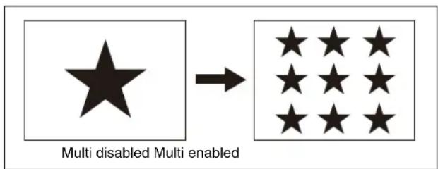
1 Open the Home > M/E-1 > Bus/Transition > Wipe > Main Modify menu (11109.35).
2 Set the [Multi] button to the on state and set the following parameters.
| No. | Parameter Adjustment |
| 1 H | Multi Number of repetitions of pattern horizontally |
| 2 V | Multi Number of repetitions of pattern vertically |
| 3 Shift | Pattern layout |
To adjust replicated patterns
In the [Multi Adjust] group in the Home > M/E-1 > Bus/Transition > Wipe > Main Modify menu (11109.35), select a pattern adjustment method.
H Invert: Invert the horizontal orientation of patterns alternately.
V Invert: Invert the vertical orientation of patterns alternately.
Non Mask: Ensure a pattern is always visible on the screen, even when the position function is used to move the pattern position.
Position: Move a pattern within the pattern area divisions set by repetition (Multi).
When the [Position] button is selected, set the following parameters.
| No. | Parameter Adjustment |
| 1 | Position H Horizontal positionNegative values move right.Positive values move left. |
| 2 | Position V Vertical positionNegative values move down.Positive values move up. |
Making a wipe pattern like a window blind (Pairing)
You can use a pattern to create a window blind effect with slats in the horizontal or vertical direction.
![graph LR A["Black Square"] --> B["Barcode"] style A fill:#fff,stroke:#000 style B fill:#fff,stroke:#000 note right of B: "Pairing enabled Pairing d"](/content/2026/06/1382172/images/2e25796b6c71fa69db618642fa7a2ad5319ad0cbb828c61335d63be98df6dbf6.jpg)
1 Open the Home > M/E-1 > Bus/Transition > Wipe > Main Modify menu (11109.35).
2 Set the [Pairing] button to the on state and set the following parameters.
| No. | Parameter Adjustment |
| 1 Width Width | |
| 2 H Offset Spacing in the horizontal directionNegative values move the even-numbered group to the left, and the odd-numbered group move to the right.Positive values move the even-numbered group to the right, and the odd-numbered group move to the left. | |
| 3 V Offset Spacing in the vertical directionNegative values move the even-numbered group up, and the odd-numbered group down.Positive values move the even-numbered group down, and the odd-numbered group up. | |
Adding modulation to a wipe pattern (Modulation)
H (horizontal modulation)
This modulates the pattern in the horizontal direction.

V (vertical modulation)
This modulates the pattern in the vertical direction.

Fringe (radial modulation)
This modulates the pattern in the radial direction.

1 Open the Home > M/E-1 > Bus/Transition > Wipe > Main Modify menu (11109.35). 2 In the [Modulation] group, select a modulation type. Set the following parameters.
| No. | Parameter Adjustment |
| 1 | Amplitude Amplitude of modulation |
| 2 | Frequency Frequency of modulation |
| 3 | Speed Speed of ripplesNegative values create waves in the down, left, and counterclockwise directions.Positive values create waves in the up, right, and clockwise directions. |
| 4 | Shape Modulation waveform a) |
a) 1: Sine wave, 2: Triangle wave, 3: Square wave
Warping the edges of a wipe pattern (Spring)
This warps the edges of a pattern inward or outward.
![graph LR A["Black Square"] --> B["Black Rounded Square"] style A fill:#fff,stroke:#000 style B fill:#fff,stroke:#000 note right of B: "Spring enabled Spring d"](/content/2026/06/1382172/images/28414e619de177274e8230c99585f0a208e610393cdb305525f3dc2c2d19dddd.jpg)
1 Open the Home > M/E-1 > Bus/Transition > Wipe > Main Modify menu (11109.35). 2 Set the [Spring] button to the on state and set the following parameter.
| No. | Parameter Adjustment |
| 1 | Width Size and direction of the warpA value of -100.00 corresponds to maximum inward warpage.A value of +100.00 corresponds to maximum outward warpage. |
Adding a spiral effect to a wipe pattern (Spiral)
This transforms the pattern into a spiral pattern.

1 Open the Home > M/E-1 > Bus/Transition > Wipe > Main Modify menu (11109.35). 2 Set the [Spiral] button to the on state and set the following parameters.
 |
Setting an Independent Key Transition Wipe
Wipe patterns and modifiers for independent key transitions are configured using the menu. This section describes the M/E-1 key 1 menu as an example.
Setting a Wipe Pattern for an Independent Key Transition
Selecting a wipe pattern
Note
Only standard wipe patterns can be used in an independent key transition.
1 Open the Home > M/E-1 > Key1 > Transition > Wipe menu (11101.52). 2 Press the [Pattern Select] button. A pattern selection window appears. 3 Set the button for the target wipe pattern to the on state. 4 Press [OK].
Setting Independent Key Transition Wipe Modifiers
You can set the following modifiers in an independent key transition.
- Direction
- Soft edge
- Position
- Rotation
- Aspect
- Multiplication
Setting the wipe direction (Direction)
1 Open the Home > M/E-1 > Key1 > Transition > Wipe menu (11101.52). 2 In the [Direction] group, select a wipe direction. Normal: Wipe in normal direction.
Normal/Reverse: Alternate directions between normal and reverse after each transition.
Reverse: Wipe in the opposite direction of the normal direction.
Softening the wipe pattern edge (Soft edge)
Softens the edges of a pattern.
1 Open the Home > M/E-1 > Key1 > Transition > Wipe menu (11101.52). 2 Set the [Soft] button to the on state and set the following parameter.
| No. | Parameter Adjustment | |
| 1 Soft | Edge softness |
Setting the wipe pattern position (Position)
You can move a wipe pattern to a desired position.
1 Open the Home > M/E-1 > Key1 > Transition > Wipe menu (11101.52).
2 Set the [Position] button to the on state and set the following parameters.
| No. | Parameter Adjustment |
| 1 | Position H Horizontal positionNegative values move left.Positive values move right. |
| 2 | Position V Vertical positionNegative values move down.Positive values move up. |
To return a pattern from a moved position to the center of the screen as a transition progresses Set the [Auto Center] button to the on state.
Rotating a wipe pattern (Rotation)
1 Open the Home > M/E-1 > Key1 > Transition > Wipe menu (11101.52).
2 In the [Rotation] group, select a rotation type.
Angle: Wipe with a pattern at a fixed angle.
Speed: Rotate a pattern at a fixed speed.
Magnitude: Rotate a pattern through the specified angle in a single transition.
When the [Angle] button is selected, set the following parameter.
| No. | Parameter Adjustment |
| 1 | Angle Inclination angle of patternA value of -100.00 corresponds to a rotation of one turn counterclockwise.A value of +100.00 corresponds to a rotation of one turn clockwise.A value of 0.00 corresponds to no rotation. |
When the [Speed] button is selected, set the following parameter.
| No. | Parameter Adjustment |
| 1 | Speed Rotation speed of patternA value of -100.00 corresponds to 1 revolution/second counterclockwise rotation.A value of +100.00 corresponds to 1 revolution/second clockwise rotation.A value of 0.00 corresponds to no rotation (stationary). |
When the [Magnitude] button is selected, set the following parameters.
| No. | Parameter Adjustment | |
| 1 | Angle Angle of pattern | at start of transitionA value of -100.00 corresponds to a rotation of one turn counterclockwise.A value of +100.00 corresponds to a rotation of one turn clockwise.A value of 0.00 corresponds to no rotation. |
| 2 | Magnitude Angle of rotation | at throught course of transitionA value of -200.00 corresponds to a rotation of two turns counterclockwise.A value of +200.00 corresponds to a rotation of two turns clockwise.A value of 0.00 corresponds to no rotation. |
Setting the aspect ratio of a wipe pattern (Aspect)
You can change the aspect ratio of a pattern.
1 Open the Home > M/E-1 > Key1 > Transition > Wipe menu (11101.52).
2 Set the [Aspect] button to the on state and set the following parameter.
| No. | Parameter Adjustment |
| 1 | Aspect Aspect ratioNegative values expand vertically.Positive values expand horizontally. |
Replicating a wipe pattern (Multi)
You can replicate a pattern horizontally, vertically, or both up to 63 times.
You can select from four types of pattern layout in an independent key transition.

1: All patterns in the same orientation 2: Even-numbered rows moved horizontally 3: Even-numbered columns flipped horizontally, even-numbered rows flipped vertically 4: Even-numbered columns flipped horizontally, even-numbered rows flipped vertically and moved horizontally
1 Open the Home > M/E-1 > Key1 > Transition > Wipe menu (11101.52). 2 Set the [Multi] button to the on state and set the following parameters.
| No. | Parameter Adjustment |
| 1 H | Multi Number of repetitions of pattern horizontally |
| 2 V | Multi Number of repetitions of pattern vertically |
| 3 Invert Type Pattern layout (1 to 4) | |
Wipe Snapshots
You can save a snapshot of a wipe pattern together with all modifiers and pattern limit settings in a register for recall when required. There are ten wipe snapshot registers on each switcher bank.
For details about editing a wipe snapshot register, see "Wipe Snapshot Register Operations" (page 301).
Saving and recalling a wipe snapshot can be performed using the Flexi Pad control block or the menu.
Wipe Snapshot Operations (Flexi Pad Control Block)
You can configure a wipe snapshot using the Flexi Pad control block of the target switcher bank.
Memory recall section in wipe snapshot operation mode
The illustration shows the ICP-X7000 Flexi Pad control block. The operation for the ICP-X1000 series Flexi Pad control block is the same.

Pressing the [WIPE] button in the Flexi Pad control block switches the memory recall section to wipe snapshot operation mode.
You can select wipe snapshot registers (1 to 10) using the buttons in the memory recall section.
The wipe pattern icon is displayed on buttons for registers with a registered snapshot.
The register number is displayed on buttons for registers without a registered snapshot.
The wipe pattern number is displayed on the top right button in the memory recall section.
The button color varies as follows, according to the register state.
Gray characters: Register not containing a registered snapshot
White icon/text: Register containing a registered snapshot
Lit orange: Last recalled register
Notes
- The register name is displayed instead of the wipe pattern icon on buttons for registers with a registered snapshot. The register number is displayed if a register name has not been configured.
For details about setting the button display, see "Setting the button display in wipe snapshot operation mode/DME wipe snapshot operation mode" (page 445).
- When both the main pattern and sub pattern are selected for a pattern mix, the main pattern icon is displayed.
Selecting a wipe pattern
1 Press the [WIPE] button.
The memory recall section switches to wipe snapshot operation mode.
2 Press the [PTN NO.] button.
The memory recall section switches to numeric keypad mode.
3 Enter a pattern number and press the [ENTER] button.
The memory recall section returns to wipe snapshot operation mode. The selected pattern number is displayed on the top right button in the memory recall section.
Saving a wipe snapshot
Set a wipe and save a wipe snapshot register using the following procedure.
1 Press the [WIPE] button.
The memory recall section switches to wipe snapshot operation mode.
2 Press and hold the [WIPE] button and press the button for the target register to save.
The register button is lit orange and the wipe settings are saved in the snapshot.
Note
If you press a register button in which a wipe snapshot is already saved, the register data will be overwritten.
Recalling a wipe snapshot
1 Press the [WIPE] button.
The memory recall section switches to wipe snapshot operation mode.
2 Press the button for the target register to recall.
The register button is lit orange and the wipe snapshot is recalled.
To undo a register recall
To undo a recall immediately after recalling a register, press the [UNDO] button.
Deleting a wipe snapshot
1 Press the [WIPE] button.
The memory recall section switches to wipe snapshot operation mode.
2 Press and hold the [DEL] button and press the button for the target register to delete.
The wipe snapshot is deleted and the register button changes to register number display.
Wipe Snapshot Operations (Menu)
The same memory recall buttons as in the memory recall section of the Flexi Pad control block are displayed in the Bus/Transition > Wipe > Wipe Snapshot menu on the switcher bank. The settings and display of the memory recall buttons in the Flexi Pad control block and in the menu are linked.
This section describes the M/E-1 menu as an example.
Selecting a wipe pattern
1 Open the Home > M/E-1 > Bus/Transition > Wipe > Wipe Snapshot menu (11109.37).
2 Press the [Current Pattern] button and enter a pattern number in the numeric keypad window.
The icon for the selected wipe pattern is displayed on the right side of the [Current Pattern] button.
Saving a wipe snapshot
Set a wipe and save a wipe snapshot register using the following procedure.
1 Open the Home > M/E-1 > Bus/Transition > Wipe > Wipe Snapshot menu (11109.37).
2 Press the [Store] button in the [Mode] group.
3 Press the button for the target register to save.
The register button is lit orange and the wipe settings are saved in the snapshot.
Note
If you press a register button in which a wipe snapshot is already saved, the register data will be overwritten.
Recalling a wipe snapshot
1 Open the Home > M/E-1 > Bus/Transition > Wipe > Wipe Snapshot menu (11109.37).
2 Press the [Recall] button in the [Mode] group.
3 Press the button for the target register to recall.
The register button is lit orange and the wipe snapshot is recalled.
Deleting a wipe snapshot
1 Open the Home > M/E-1 > Bus/Transition > Wipe > Wipe Snapshot menu (11109.37).
2 Press the [Delete] button in the [Mode] group.
3 Press the button for the target register to delete.
The wipe snapshot is deleted and the register button changes to register number display.
Overview
A DME wipe is a function that uses a DME effect to switch from the current output image to a new image. You can also switch the background and insert/remove keys depending on the DME wipe.
There are two types of DME wipe: DME wipes that can be set in a common transition, and DME wipes that can be set in an independent key transition.
When the system signal format is 2160P, a box DME can be set for use as DME Ch1/2 or as DME Ch3/4 using the Home > Setup > Switcher > Box Settings > DME/FM Channel Assign menu (19103.53).
For details about assigning a DME channel, see “Setting DME/Frame Memory Channels” (page 425).
If you operate a channel on another box that has the same channel configured, the operation of the boxes is linked.
Resizer DME wipes
You can execute a DME wipe using a resizer in transitions with a key selected for a next transition and in independent key transitions.
Notes
- To use the DME function, the MZS-X1610 3D DME License (option) is required for each target box.
- When the system signal format is 2160P, the DME function must be enabled for use. When the DME function is disabled, only resizer DME wipes can be set. For details about setting GPU functions, see “Setting a GPU” (page 384).
- A resizer DME wipe cannot be used on additional keys.
- The number of DME channels that can be used will vary, depending on the system signal format and the DME enhanced function mode setting. For details, see “DME channels” (page 204).
DME wipe patterns
DME wipe patterns are classified into the following groups. Also, there are three DME wipe execution modes, depending on the number of DME channels available: 1-channel mode, 2-channel mode, and 3-channel mode.
For the pattern images, see “DME Wipe Pattern List” (page 539) and “Resizer DME Wipe Pattern List” (page 543).
Note
When the system signal format is not 2160P and both DME channels 1 and 2 are set to enhanced function mode, 3-channel mode DME wipe patterns cannot be set.
| Pattern group Description | |
| Slide The new image | slides in over the current image. |
| Squeeze The new image | image appears reduced over the current image, and is progressively enlarged to cover it. |
| Split The current image | image splits, and the new image appears in the gap. |
| Door The new image | moves in like a door closing, and progressively covers the current image. |
| Flip Tumble The current image | image rotates about an axis and is replaced by the new image. During the transition, the signal from the utility 2 bus appears as the background. |
| Page Turn The new image | image moves like a page turning over the current image. |
| Roll The new image | unrolls like a scroll over the current image. |
| Frame I/O (Frame in/out) | Completed in two transitions. In the first transition, the new image comes into frame with the current image. In the second transition, the new image goes out of frame and the current image is restored. |
| P in P (Picture-in-picture) | In 1-channel mode:Completed in two transitions.In the first transition, the current image shrinks, and the new image appears behind it. In the second transition, the current image expands to its original size.In 2-channel mode:In the first half of the transition, the current image shrinks and the new image appears behind it. In the second half of the transition, the new image expands, and the current image disappears.You can move the pattern from the current position by a relative amount. During the transition, the signal from the utility 2 bus appears as the background. |
| Mosaic In the first half of the tran sition, a mosaic is gradually applied so that the current image switches to the new image by the 50% point. In the second half of the transition, the mosaic effect on the new image is gradually reversed, returning to the original image at 100%. | |
| Defocus In the first half of th e transition, the defocus effect is gradually applied so that the current image switches to the new image by the 50% point. In the second half of the transition, the defocus effect on the new image is gradually reversed, returning to the original image at 100%.Enhanced function mode DME channels can be used. | |
| Crop Slide The current image is cropped in half as the new image appears, displaying both images side by side. Then, the cropped images slide sideways to show only the new image. | |
| Brick In 2-channel mode:A brick with visible side surface slides in over the current image, then rotates so that the new image becomes visible.In 3-channel mode:A brick appears over the current image, expanding and rotating, and switches to the new image. | |
| Resizer Slide Executes a Slide DME wipe using a resizer. | |
| Resizer Squeeze Executes a Squeeze DME wipe using a resizer. | |
| Resizer Frame I/O Executes a Frame I/O DME wipe using a resizer. | |
DME wipe execution mode and pattern numbers
The execution modes and pattern numbers supported in each DME wipe pattern group are shown in the following table.
Depending on the DME wipe pattern, there are patterns that can be used for backgrounds (transition with background selected for next transition) and patterns that can be used for keys (transition with key selected for next transition or independent key transition).
O: Supported
×: Not supported
| Pattern group | Execution mode | Pattern number | Background a) | Keys b) |
| Slide 1ch | 1001 to | 1008 | ○ | ○ |
| 2ch 2601 to | 2608 | ○× | ||
| Squeeze | 1ch 1021 to | 1033 | ○ | ○ |
| 2ch 262 | 1 to 2628 | ○× | ||
| Split 1ch | 101 | 1 to 1013 | ○ | ○ |
| Door 1ch | 1041 to | 1044 | ○ | ○ |
| Flip Tumble | 1ch 110 | 1, 1102 | ○× | |
| Page Turn | 1ch 130 | 1 to 1313, 1315 to 1318, 1341 to 1345 | ○ | ○ |
| 2ch 2701 to | 2713, 2715 to 2718, 2741 to 2745 | ○ | ○ | |
| Roll | 1ch 1321 to | 1333, 1335 to 1338, 1346 to 1350 | ○ | ○ |
| 2ch 2721 to | 2733, 2735 to 2738, 2746 to 2750 | ○ | ○ | |
| Frame I/O | 1ch 1201 to | 1209, 1221 to 1225 | ○ | ○ |
| 2ch 2851 to | 2854, 2861 to 2864 | ○× | ||
| P in P | 1ch | 1251 | ○ | × |
| 2ch | 2651, 2652 | ○ | × | |
| Mosaic | 1ch | 1701 | ○ | × |
| Defocus | 1ch | 1702 | ○ | × |
| Crop Slide | 2ch 2661, | 2662 ○x | ||
| Brick 2ch | 2801 to | 2804, 2811 to 2814 | ○x | |
| 3ch 3601 | ○x | |||
| Resizer Slide | 1ch 7001 to | 7008 | ×○ | c) |
| Resizer Squeeze | 1ch 7021 to | 7031 | ×○ | c) |
| Resizer Frame I/O | 1ch 7201 to | 7208, 7221 to 7224 | ×○ | c) |
a) Transition with a background selected for a next transition b) Transition with a key selected for a next transition or an independent key transition c) Cannot be used on additional keys (×)
DME wipe pattern modifiers
You can add various modifiers to a DME wipe pattern, such as setting the DME wipe direction and pattern position.
Pattern limit
You can specify the transition execution limit of a DME wipe.
For details, see "Pattern Limit" (page 116).
Note
In an independent key transition, a pattern limit cannot be used.
DME wipe restrictions
Relationship with processed keys
- In DME wipes and processed keys, only enabled DME channels on the switcher bank can be used. When using a DME in a processed key, an available DME channel is automatically assigned for DME wipes. If all DME channels are in use, then a DME wipe cannot be used. For details about setting DME channels, see “Setting a DME channel to use in a switcher bank” (page 413).
- DME wipes and resizer DME wipes cannot be used on keys that use a DME in a processed key.
Relationship with the image effect function
It is not possible to use background DME wipes when the image effect function is set.
Relationship with resizers
- DME wipes and resizer DME wipes cannot be used on keys with a resizer enabled.
- When a dual resizer effect is set on either of the two keys, DME wipes and resizer DME wipes cannot be used on the other key.
Number of DME channels that can be used simultaneously
DMEs can be used in up to two locations simultaneously on a single switcher bank (processed key with DME wipe).
The number of DME channels that can be used on a key depends on the DME wipe pattern execution mode, as given below.
When not using a DME wipe:
One DME channel each on two keys, or one to four DME channels on a single key can be used.
When using a 1-channel mode DME wipe:
One DME channel on a single key only can be used.
When using a 2-channel mode or 3-channel mode DME wipe:
DMEs cannot be used on keys.
Notes
- In multi program 2 mode, DMEs can be used in up to two locations (main and sub).
- When M/E split is enabled, one DME channel can be used on each of the two sub blocks.
Recalling a snapshot/keyframe
Picture flashing may occur when executing a snapshot or keyframe that uses a DME wipe. To prevent picture flashing from occurring, a flash prevention bus must be configured.
For details about setting a flash prevention bus, see "Configuring a Flash Prevention Bus for when Recalling DME Effects" (page 422).
Setting a DME Wipe
DME wipe patterns and modifiers are configured using the menu.
This section describes the M/E-1 menu as an example.
Setting a DME Wipe Pattern
Selecting a DME wipe pattern
1 Open the DME wipe pattern selection menu.
In 1-channel mode, open the Home > M/E-1 > Bus/Transition > DME Wipe > 1ch Pattern menu (11109.41).
In 2-channel mode, open the Home > M/E-1 > Bus/Transition > DME Wipe > 2ch Pattern menu (11109.42).
In 3-channel mode, open the Home > M/E-1 > Bus/Transition > DME Wipe > 3ch Pattern menu (11109.43).
2 Press the button for a DME wipe pattern group.
The patterns in the selected group are displayed.
For 1-channel mode
Select from the following DME wipe pattern groups.
Slide / Squeeze: Slide and squeeze
Split / Door: Split and door
Flip Tumble: Flip tumble
Page Turn: Page turn
Roll: Roll
Frame I/O / P in P: Frame in/out and picture-in-picture
Mosaic / Defocus: Mosaic and defocus
Resizer Slide / Squeeze: Resizer slide and squeeze
Resizer Frame I/O: Resizer frame in/out
For 2-channel mode
Select from the following DME wipe pattern groups.
Slide / Squeeze: Slide and squeeze
P in P: Picture-in-picture
Crop Slide: Crop slide
Page Turn: Page turn
Roll: Roll
Frame I/O: Frame in/out
Brick: Brick
For 3-channel mode
Select from the following DME wipe pattern groups.
Brick: Brick
3 Set the button for the target DME wipe pattern to the on state.
Adjusting DME wipe pattern parameters
When the following patterns are selected, set the parameters.
Squeeze (1-channel mode) pattern numbers 1032, 1033
Crop Slide (2-channel mode) pattern numbers 2661, 2662
| No. | Parameter Adjustment | |
| 1 | Holding Level Position | for entering the dead band a) |
| 2 | Tolerance Width of the | dead band |
a) Set relative to a transition start point of 0% and end point of 100%.
Page Turn (1-channel mode) pattern numbers 1301 to 1313, 1315 to 1318, 1341 to 1345
Page Turn (2-channel mode) pattern numbers 2701 to 2713, 2715 to 2718, 2741 to 2745
Roll (1-channel mode) pattern numbers 1321 to 1333, 1335 to 1338, 1346 to 1350
Roll (2-channel mode) pattern numbers 2721 to 2733, 2735 to 2738, 2746 to 2750
| No. | Parameter Adjustment |
| 1 | Radius Radius of the turned page flap/rolled-up portion a) |
| 2 | Magnitude Angle of rotation through course of transition b) |
| 3 | Start Angle Angle at start of transition b) |
a) 0% is an effect like a turned page, 100% is normal curl, and 200% is radius with double the normal curl. b) -100.00 is rotation in the counterclockwise direction, +100.00 is rotation in the clockwise direction, and 0.00 is no rotation.
Brick (2-channel mode) pattern numbers 2801 to 2804, 2811 to 2814
| No. | Parameter Adjustment |
| 1 | Side V Size X Side V horizontal scaling factor |
| 2 | Side V Size Y Side V vertical scaling factor |
| 3 | Height Height of brick |
| 4 | Center X Horizontal center position a) |
| 5 | Center Y Vertical center position b) |
a) Side V image horizontal center position. At -100.00, the center is at the left edge of the screen. At +100.00, the center is at the right edge of the screen. b) Side V image vertical center position. At -100.00, the center is at the bottom edge of the screen. At +100.00, the center is at the top edge of the screen.
Frame I/O (2-channel mode) pattern numbers 2851 to 2854
| No. | Parameter Adjustment |
| 1 Delay | Timing for image selected on a utility bus to enter the frame |
Frame I/O (2-channel mode) pattern numbers 2861 to 2864
| No. | Parameter Adjustment | |
| 1 | Rot X | Rotation around Y-axis (rotation in horizontal direction) |
| 2 | Rot Y | Rotation around X-axis (rotation in vertical direction) |
| 3 | Rot Z | Rotation around Z-axis |
| 5 | Delay Timing for image | selected on a utility bus to enter the frame |
Brick (3-channel mode) pattern number 3601
| No. | Parameter Adjustment |
| 1-1 | Side V Size X Side V horizontal scaling factor |
| 1-2 | Side V Size Y Side V vertical scaling factor |
| 1-3 | Height Height of brick a) |
| 1-4 | Side V Center X Side V horizontal center position b) |
| 1-5 | Side V Center Y Side V vertical center position c) |
| 2-1 | Side H Size X Side H horizontal scaling factor |
| 2-2 | Side H Size Y Side H vertical scaling factor |
| 2-3 | Height Height of brick a) |
| 2-4 | Side H Center X Side H horizontal center position b) |
| 2-5 | Side H Center Y Side H vertical center position c) |
a) The [Height] parameter in numbers 1-3 and 2-3 are common. b) Side V/side H image horizontal center position. At -100.00, the center is at the left edge of the screen. At +100.00, the center is at the right edge of the screen. c) Side V/side H image vertical center position. At -100.00, the center is at the bottom edge of the screen. At +100.00, the center is at the top edge of the screen.
Setting Modifiers
You can add modifiers to modify a DME wipe pattern.
Direction
Sets the direction of travel of the DME wipe.
Notes
- The direction cannot be set for the following patterns.
- Frame I/O pattern numbers 1201, 1202, 1203, 1205, 1206, 1208, 1209, 1225
- P in P pattern number 1251 – Mosaic pattern number 1701
- Defocus pattern number 1702
- In a key DME wipe, the direction can be set for the following patterns.
- Frame I/O pattern numbers 1204, 1207, 1221 to 1224
- Resizer Frame I/O pattern numbers 7204, 7207, 7221 to 7224
Edge
Adds a border to a DME wipe pattern.
Note
The edges cannot be set for the following patterns.
- Split pattern numbers 1011, 1012, 1013 • Mosaic pattern number 1701 • Defocus pattern number 1702
Position
You can move a DME wipe pattern to a desired position. You can move to a specified position (upper left, upper right, bottom left, bottom right) using Position Select. The position can be set for the following patterns.
The target position and movement varies depending on the pattern.
- Squeeze pattern number 1031
Resizer Squeeze pattern number 7031
As the transition progresses, the pattern center automatically moves from the initial set position toward the center of the screen.
- Squeeze pattern numbers 1032, 1033
You can set the pattern position at the start of the transition. As the transition progress resumes after the dead band, the pattern automatically moves from the initial position toward the center of the screen.
- Frame I/O pattern numbers 1201 to 1209, 1221 to 1225 P in P pattern number 1251
Resizer Frame I/O pattern numbers 7201 to 7208, 7221 to 7224
You can set the pattern position at the end of the first transition.
• P in P pattern numbers 2651, 2652
You can configure each channel separately, or configure two channels simultaneously, depending on their relative positions.
- Brick pattern numbers 2801 to 2804, 2811 to 2814
You can set the vertical position where the brick slides in.
- Frame I/O pattern numbers 2851 to 2854, 2861 to 2864 You can set the pattern position at the end of the first transition for each channel.
Size
Sets the size of a DME wipe pattern.
Note
The size can be set for the following patterns.
• Frame I/O pattern numbers 1201 to 1209, 1221 to 1225, 2851 to 2854, 2861 to 2864 • P in P pattern numbers 1251, 2651, 2652 - Resizer Frame I/O pattern numbers 7201 to 7208, 7221 to 7224
Crop
Crops the top, bottom, left, right sides of a DME wipe pattern.
Note
Cropping cannot be set for the following patterns.
• Mosaic pattern number 1701 • Defocus pattern number 1702 • Crop Slide pattern numbers 2661, 2662
Target channel for modifiers
For DME wipe patterns in 1-channel mode, the 1st channel becomes the target.
For DME wipe patterns in 2-channel mode, select the target channel from the 1st channel and 2nd channel. For DME wipe patterns in 3-channel mode, select the target channel from the 1st channel, 2nd channel, and 3rd channel. You can select multiple channels. Depending on the DME wipe pattern and modifiers, all channels may be controlled by the 1st channel.
Note
Channels cannot be selected for the direction setting.
Specifying the DME wipe pattern direction (Direction)
1 Open the Home > M/E-1 > Bus/Transition > DME Wipe > Edge/Direction menu (11109.44). 2 In the [Direction] group, select a DME wipe direction.
Normal: DME wipe in normal direction.
Normal/Reverse: Alternate directions between normal and reverse after each transition.
Reverse: DME wipe in the opposite direction of the normal direction.
To set the wipe direction using buttons in the transition control block
You can set the DME wipe direction using the transition control block/transition control block (simple type) of the target switcher bank.
Note
The buttons used for configuring the DME wipe direction must be assigned to the transition control block/transition control block (simple type) beforehand.
For details about assigning buttons, see "Assigning Control Panel Buttons" (page 428).
On the transition control block, use the following wipe direction selection buttons.
[NORM] button: Normal
[NORM/REV] button: Normal/Reverse
[REV] button: Reverse
On the transition control block (simple type), use the following wipe direction selection buttons.
[NORM/REV] button: Normal/Reverse [REV] button (when not lit): Normal [REV] button (when lit): Reverse
Modifying a DME wipe pattern edge (Edge)
1 Open the Home > M/E-1 > Bus/Transition > DME Wipe > Edge/Direction menu (11109.44). 2 In the [Ch Select] group, select the target channel to set. 3 In the [Edge] group, select a type of edge.
Border: Adds a border to a pattern.
Soft Border: Softens a border applied to a pattern. When the [Border] button is selected, set the following parameters.
| No. | Parameter Adjustment |
| 1 | Width Border width |
| 3 | Luminance Luminance |
| 4 | Saturation Saturation |
| 5 | Hue |
When the [Soft Border] button is selected, set the following parameters.
| No. | Parameter Adjustment | |
| 1 | Width Border width | |
| 2 | Inner Soft Softness of border | inner edge of border |
| 3 | Luminance Luminance | |
| 4 | Saturation Saturation | |
| 5 | Hue | Hue |
Note
When multiple channels are selected, the setting values for the channel with the lowest number are displayed. When you adjust the setting values, this adjusts the settings on the other channels by the same amount.
Setting the DME wipe pattern position (Position)
1 Open the Home > M/E-1 > Bus/Transition > DME Wipe > Modify menu (11109.45). 2 In the [Ch Select] group, select the target DME channel to set.
3 Set the [Position] button in the [Position] group to the on state and set the following parameters.
| No. | Parameter Adjustment | |
| 1 H | a) | Horizontal positionNegative values move left.Positive values move right. |
| 2 V | Vertical position | Negative values move down.Positive values move up. |
a) Not displayed when a 2-channel mode Brick pattern (pattern numbers 2801 to 2804, 2811 to 2814) is selected.
When a 2-channel mode P in P pattern (pattern numbers 2651, 2652) is selected, set the relative position using the following parameters.
| No. | Parameter Adjustment |
| 4 | Relative H Relative position in the horizontal direction |
| 5 | Relative V Relative position in the vertical direction |
To return the pattern position to the center of the screen
Press the [Center] button in the [Position] group.
Displaying/moving the DME wipe pattern position (Position Select)
1 Open the Home > M/E-1 > Bus/Transition > DME Wipe > Modify menu (11109.45). 2 In the [Ch Select] group, select the target DME channel to set. 3 In the [Position Select] group, select a move position.
Top Left: Top left corner
Top Right: Top right corner
Bottom Left: Bottom left corner
Bottom Right: Bottom right corner
The button for the current pattern position is in the on state. When the pattern position is at the center of the screen, all four buttons are in the on state.
Note
When multiple channels are selected, the 1st channel becomes the target for movement.
Setting the DME wipe pattern size (Size)
1 Open the Home > M/E-1 > Bus/Transition > DME Wipe > Modify menu (11109.45).
2 In the [Ch Select] group, select the target DME channel to set. 3 Set the [Size] button to the on state and set the following parameter.
| No. | Parameter Adjustment | |
| 1 Size | Size | |
Note
When multiple channels are selected, the setting values for the channel with the lowest number are displayed. When you adjust the setting values, this adjusts the settings on the other channels by the same amount.
Setting the DME wipe pattern cropping (Crop)
1 Open the Home > M/E-1 > Bus/Transition > DME Wipe > Modify menu (11109.45). 2 In the [Ch Select] group, select the target DME channel to set. 3 Set the [Crop] button in the [Crop Mode] group to the on state and set the following parameters.
| No. | Parameter Adjustment | |
| 1-1 H | Simultaneous adjustment of crop of left and right edges | |
| 1-2 V | Simultaneous adjustment of crop of top and bottom edges | |
| 1-3 All | Simultaneous adjustment of crop of top, bottom, left, and right edges | |
| 2-1 Top | Crop of top edge | |
| 2-2 Left | Crop of left edge | |
| 2-3 Right | Crop of right edge | |
| 2-4 Bottom | Crop of bottom edge | |
Note
When multiple channels are selected, the setting values for the channel with the lowest number are displayed. When you adjust the setting values, this adjusts the settings on the other channels by the same amount.
To crop to 4:3 aspect ratio
Press the [4:3 Crop] button in the [Crop Mode] group.
To set the movement during transition execution In the [Crop Transition] group, select the crop operation as the transition executes.
Cut: The cropping does not change during the transition, and the cropping is removed after the transition has completed. Last 5%: The cropping is maintained for the first 95% of the transition, and is removed during the last 5% of the transition. Linear: The cropping is removed from the start of the transition through the course of the transition.
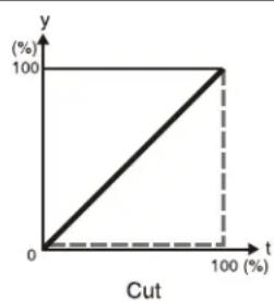


t: Transition execution time
y: Change in transition and cropping amount
To set the timing of transition completion
When the [Last 5%] button in the [Crop Transition] group is selected, you can set the transition completed timing to 70%, 95%, or 100% of the execution time.
In the [Release Transition] group, select the timing of transition completion.
Last 30%: The transition completes at the 70% point of the transition progress. The transition interval from 70% to 95% becomes a dead band. The cropping is removed during the last 5% of the transition.
Last 5%: The transition completes at the 95% point of the transition progress. The cropping is removed during the remaining 5%.
Off: The transition completes at the 100% point. During the last 5% of the transition, the transition and cropping removal proceed together.
Setting an Independent Key Transition DME Wipe
DME wipe patterns and modifiers for independent key transitions are configured using the menu. This section describes the M/E-1 key 1 menu as an example.
Setting a DME Wipe Pattern for an Independent Key Transition
Note
In an independent key transition, wipe pattern parameters cannot be adjusted.
Selecting a DME wipe pattern
1 Open the DME wipe pattern selection menu.
In 1-channel mode, open the Home > M/E-1 > Key1 > Transition > 1ch Pattern menu (11101.54).
In 2-channel mode, open the Home > M/E-1 > Key1 > Transition > 2ch Pattern menu (11101.55).
2 Press the button for a DME wipe pattern group.
The patterns in the selected group are displayed.
For 1-channel mode
Select from the following DME wipe pattern groups.
Slide / Squeeze: Slide and squeeze
Split / Door: Split and door
Page Turn: Page turn
Roll: Roll
Frame I/O: Frame in/out
Resizer Slide / Squeeze: Resizer slide and squeeze
Resizer Frame I/O: Resizer frame in/out
For 2-channel mode
Select from the following DME wipe pattern groups.
Page Turn: Page turn
Roll: Roll
3 Set the button for the target wipe pattern to the on state.
Setting Independent Key Transition DME Wipe Modifiers
For details about the supported modifiers, see “Setting Modifiers” (page 176).
Setting the DME wipe direction (Direction)
1 Open the Home > M/E-1 > Key1 > Transition > DME Wipe menu (11101.53).
2 In the [Direction] group, select a DME wipe direction.
Normal: DME wipe in normal direction.
Normal/Reverse: Alternate directions between normal and reverse after each transition.
Reverse: DME wipe in the opposite direction of the normal direction.
Modifying a DME wipe pattern edge (Edge)
1 Open the Home > M/E-1 > Key1 > Transition > DME Wipe menu (11101.53).
2 In the [Edge] group, select a type of edge.
Border: Adds a border to a pattern.
Soft Border: Softens a border applied to a pattern. When the [Border] button is selected, set the following parameters.
| No. | Parameter Adjustment |
| 1 | Width Border width |
| 3 | Luminance Luminance |
| 4 | Saturation Saturation |
| 5 | Hue |
When the [Soft Border] button is selected, set the following parameters.
| No. | Parameter Adjustment | |
| 1 | Width Border width | |
| 2 | Inner Soft Softness of border | inner edge of border |
| 3 | Luminance Luminance | |
| 4 | Saturation Saturation | |
| 5 | Hue | Hue |
Setting the DME wipe pattern position (Position)
1 Open the Home > M/E-1 > Key1 > Transition > DME Wipe menu (11101.53).
2 Set the [Position] button in the [Position] group to the on state and set the following parameters.
| No. | Parameter Adjustment | |
| 1 H | Horizontal position | Negative values move left.Positive values move right. |
| 2 V | Vertical position | Negative values move down.Positive values move up. |
To return the pattern position to the center of the screen
Press the [Center] button in the [Position] group.
Setting the DME wipe pattern size (Size)
1 Open the Home > M/E-1 > Key1 > Transition > DME Wipe menu (11101.53).
2 Set the [Size] button to the on state and set the following parameter.
| No. | Parameter Adjustment | |
| 1 Size | Size | |
Setting the DME wipe pattern cropping (Crop)
1 Open the Home > M/E-1 > Key1 > Transition > DME Wipe menu (11101.53).
2 Set the [Crop] button in the [Crop Mode] group to the on state and set the following parameters.
| No. | Parameter Adjustment | |
| 1-1 H | Simultaneous adjustment of crop of left and right edges | |
| 1-2 V | Simultaneous adjustment of crop of top and bottom edges | |
| 1-3 All | Simultaneous adjustment of crop of top, bottom, left, and right edges | |
| 2-1 Top Crop of top edge | ||
| 2-2 Left Crop of left edge | ||
| 2-3 Right Crop of right edge | ||
| 2-4 Bottom Crop of bottom edge | ||
To crop to 4:3 aspect ratio
Press the [4:3 Crop] button in the [Crop Mode] group.
To set the movement during transition execution
In the [Crop Transition] group, select the crop operation as the transition executes.
Cut: The cropping does not change during the transition, and the cropping is removed after the transition has completed.
Last 5%: The cropping is maintained for the first 95% of the transition, and is removed during the last 5% of the transition.
Linear: The cropping is removed from the start of the transition through the course of the transition.
To set the timing of transition completion
When the [Last 5%] button in the [Crop Transition] group is selected, you can set the transition completed timing to 70%, 95%, or 100% of the execution time.
In the [Release Transition] group, select the timing of transition completion.
Last 30%: The transition completes at the 70% point of the transition progress. The transition interval from 70% to 95% becomes a dead band. The cropping is removed during the last 5% of the transition.
Last 5%: The transition completes at the 95% point of the transition progress. The cropping is removed during the remaining 5%.
Off: The transition completes at the 100% point. During the last 5% of the transition, the transition and cropping removal proceed together.
DME Wipe Snapshots
You can save a snapshot of a DME wipe pattern together with all modifiers and pattern limit settings in a register for recall when required. There are ten DME wipe snapshot registers on each switcher bank.
For details about editing a DME wipe snapshot register, see “DME Wipe Snapshot Register Operations” (page 303).
Saving and recalling a DME wipe snapshot can be performed using the Flexi Pad control block or the menu.
DME Wipe Snapshot Operations (Flexi Pad Control Block)
You can configure a DME wipe snapshot using the Flexi Pad control block of the target switcher bank.
Pressing the [DME WIPE] button in the Flexi Pad control block switches the memory recall section to DME wipe snapshot operation mode.
In DME wipe snapshot operation mode, you can save, recall, and delete DME wipe snapshots in the same way as for wipe snapshots.
For details about the method of operation, see “Wipe Snapshot Operations (Flexi Pad Control Block)” (page 170).
DME Wipe Snapshot Operations (Menu)
The same memory recall buttons as in the memory recall section of the Flexi Pad control block are displayed in the Bus/Transition > DME Wipe > DME Wipe Snapshot menu on the switcher bank. The settings and display of the memory recall buttons in the Flexi Pad control block and in the menu are linked.
In the DME Wipe Snapshot menu, you can save, recall, and delete DME wipe snapshots in the same way as for wipe snapshots.
For M/E-1 as an example, the operations are performed in the Home > M/E-1 > Bus/Transition > DME Wipe > DME Wipe Snapshot menu (11109.46).
For details about the method of operation, see “Wipe Snapshot Operations (Menu)” (page 171).
Overview
You can play frame memory video content linked to a background transition, such as a mix or wipe. A key for a clip transition is mixed with the background during execution of the transition.
Clip transition restrictions
- Pattern limits cannot be used. • Transition preview cannot be used.
- It is not possible to set the transition rate of a clip transition.
- A clip transition cannot be saved in an effect timeline as a keyframe.
- The state of a clip transition during execution cannot be saved in a snapshot.
- When recalling a snapshot that includes a clip transition while executing another clip transition, the subsequent transition does not operate properly. Recall the snapshot after the transition completes.
- When recalling a DME wipe snapshot while executing a clip transition, the image may be distorted. • Transitions executed in two strokes, such as a preset color mix when the stroke mode is set to normal mode, or a DME wipe with a picture-in-picture pattern, will not execute properly.
- When a clip transition is selected, the wipe direction selection button in the transition control block/ transition control block (simple type) that is lit indicates the playback direction of the frame memory clip.
Note
The number of channels that can be used in a clip transition will vary depending on the system signal format.
Setting a Clip Transition
This section describes clip transitions using frame memory output channels 1 and 2 on M/E-1 as an example.
Selecting a Transition Type
You can select a clip transition on a frame memory output channel to use using the transition control block, transition control block (simple type), or the menu.
To select using the transition control block Press a [FM1&FM2 CLIP] to [FM15&FM16 CLIP] button, turning it on, in the transition control block/transition control block (simple type). For frame memory output channels 1 and 2, press the [FM1&FM2 CLIP] button, turning it on.
For details, see "Setting a transition type (transition control block)" (page 109).
Note
When the system signal format is 2160P, only the [FM1&FM2 CLIP] button, [FM3&FM4 CLIP] button, and [FM5&FM6 CLIP] button, or the [FM7&FM8 CLIP] button, [FM9&FM10 CLIP] button, and [FM11&FM12 CLIP] button can be selected depending on the setting in the Home > Setup > Switcher > Box Settings > DME/FM Channel Assign menu (19103.53).
To select using the menu
In the Home > M/E-1 > Bus/Transition > Transition > Transition Type menu (11109.21), set a [FM 1&2 Clip] to [FM 15&16 Clip] button in the [Transition Type] group to the on state. For frame memory output channels 1 and 2, set the [FM 1&2 Clip] button to the on state.
For details, see "Setting the key transition type (menu)" (page 109).
Note
When the system signal format is 2160P, only the [FM 1&2 Clip]/[FM 3&4 Clip]/[FM 5&6 Clip] button or the [FM 7&8 Clip]/[FM 9&10 Clip]/[FM 11&12 Clip] button can be selected depending on the setting in the Home > Setup > Switcher > Box Settings > DME/FM Channel Assign menu (19103.53).
Setting a Clip Transition
1 Open the Home > M/E-1 > Bus/Transition > Transition > Clip Transition menu (11109.22).
2 Press the [FM1/FM2 Recall] button.
The Home > Frame Memory > FM1/FM2 > Clip/Still > Recall menu (13101.11) appears.
Select content for use in a clip transition and recall it on a frame memory output channel.
For details, see "Recalling Video" (page 194).
3 Return to the Home > M/E-1 > Bus/Transition > Transition > Clip Transition menu (11109.22).
4 Press the [Linear Key Adjust] button and set a clip transition key using the following parameters.
| No. | Parameter Adjustment | |
| 1 | Clip | Reference level for key signal generation |
| 2 | Gain | Key gain |
| 3 | Density | Key density |
5 Press the [Background Transition] button and select a background transition type from the pull-down list.
Mix: Mix
NAM: Non-additive mix
Super Mix: Super mix
Preset Color Mix: Preset color mix
Wipe: Wipe
DME Wipe: DME wipe
When [Super Mix] is selected, press the [Super Mix] button and set the parameters.
For details, see "Setting Super Mix" (page 110).
When [Preset Color Mix] is selected, press the [Preset Color Mix] button and set the parameters.
For details, see "Setting a Preset Color Mix" (page 110).
When [Wipe] is selected, press the [Wipe>Main Pattern] button to open the Home > M/E-1 > Bus/
Transition > Wipe > Main Pattern menu (11109.31) and select a wipe pattern.
For details, see "Setting a Wipe" (page 159).
When [DME Wipe] is selected, press the [DME Wipe>1ch Pattern] button to open the Home > M/E-1 > Bus/Transition > DME Wipe > 1ch Pattern menu (11109.41) and select a DME wipe pattern. To use a DME wipe pattern in 2-channel mode, open the Home > M/E-1 > Bus/Transition > DME Wipe > 2ch Pattern menu (11109.42) and select a DME wipe pattern. To use a DME wipe pattern in 3-channel mode, open the Home > M/E-1 > Bus/Transition > DME Wipe > 3ch Pattern menu (11109.43) and select a DME wipe pattern.
For details, see "Setting a DME Wipe" (page 175).
6 In the [Background Transition Timing] group, set the start position and stop position of the background transition.
To set the start position
Set using any of the following methods.
- Move the fader lever to the start position and press the [Set Start] button.
- Press the button on the right side of the [Set Start] button and enter a start position in the numeric keypad window (number of frames).
To set the stop position
Set using any of the following methods.
- Move the fader lever to the stop position and press the [Set Stop] button.
- Press the button on the right side of the [Set Stop] button and enter a stop position in the numeric keypad window (number of frames).
To reset the start position and stop position
Press the [Reset Timing] button.
7 In the [Background Transition Direction] group, set the transition direction of the background transition.
Normal: Normal
Normal/Reverse: Normal/reverse
Reverse: Reverse
Note
This can be configured only when a wipe or DME wipe is selected as the background transition type.
8 In the [FM Timing] group, set the start position and stop position of the frame memory video.
To set the start position
Set using any of the following methods.
- Move the fader lever to the start position and press the [Set Start] button.
- Press the button on the right side of the [Set Start] button and enter a start position in the numeric keypad window (number of frames).
To set the stop position
Set using any of the following methods.
- Move the fader lever to the stop position and press the [Set Stop] button.
- Press the button on the right side of the [Set Stop] button and enter a stop position in the numeric keypad window (number of frames).
To reset the start position and stop position
Press the [Reset Timing] button.
9 In the [FM Direction] group, set the frame memory video direction.
Normal: Normal
Normal/Reverse: Normal/reverse
Reverse: Reverse
To set the key priority for a clip transition key
Set the priority of the clip transition key among keys 1 to 8 and the clip transition key.
1 Press the [Key Priority/Key Assign] button.
The Home > M/E-1 > Common > Key Priority/Key Assign menu (11110.11) appears.
2 Press the [Clip Transition Priority] button and select the priority (1 to 9) of the clip transition key from the pull-down list.
Note
The priority options available for selection vary depending on the number of keys assigned to a switcher bank.
Frame Memory
Chapter
10
Overview
A frame memory is a function that freezes and captures a single frame of the input video for use as content. You can also specify a range in the input video to create a clip (frame memory series of still images).
You can also import a still image or video file created externally for use as frame memory content.
Areas Used for Frame Memory
Two areas are used for frame memory.
Frame memory work area: An area for creating and working with content.
When the system is powered off, the content in the frame memory work area will be lost.
Content storage: Area for saving created content and imported content.
When used for frame memory operations, the target content is loaded into the frame memory work area.
Number of content resources that can be stored
The number of content resources (number of frames) that can be stored in the frame memory work area is given below.
| Signal format (frequency) | Number of content resources |
| 2160P 2SI(59.94, 50, 29.97, 25, 23.98) | Approx. 1640 frames |
| 1080P(59.94, 50) | Approx. 6500 frames |
| 1080i(59.94, 50)1080PsF(29.97, 25, 23.98) | Still image content: About 6500 framesVideo content: About 3250 frames |
| 720P(59.94) | Approx. 6500 frames |
For combined content, the number of content resources (number of frames) that can be stored is halved.
Frame Memory Input and Output
There are two systems for frame memory input: frame memory source 1 bus and frame memory source 2 bus. The frame memory source bus must be assigned to the box on which you want to create still images (freeze) and video (record).
For details about the configuration method, see “Setting a Bus” (page 421).
There are 16 channels for frame memory output: FM1 to FM16. You can store and recall an image on each frame memory output channel. By assigning FM1 to FM16 to cross-point buttons, you can use frame memory output as input content.
The two frame memory input systems are assigned to two consecutive frame memory outputs (odd-numbered and even-numbered frame memory output combinations, such as FM1 & FM2 or FM3 & FM4).
Frame memory source 1 bus is used on the odd-numbered frame memory output channel, and frame memory source 2 bus is used on the even-numbered frame memory output channel.
Notes
- The number of frame memory output channels that can be used will vary depending on the system signal format.
- Frame memory operates on a box-by-box basis. For 4K, either channels FM1 to FM6 or FM7 to FM12 must be assigned to the frame memory of a box. If the same channels are assigned to different boxes, the operation of the boxes is linked.
For details about the configuration method, see "Setting DME/Frame Memory Channels" (page 425).
- When content is loaded, it is loaded into the frame memory work area of all boxes in the switchers.
- Created content can only be used on the box to which the frame memory source bus was assigned before saving to content storage. To use created content on another box, save the content in content storage, temporarily unload it and then reload it.
- When the system signal format is 4K, assign the frame memory source bus to either the box that is using FM1 to FM6 or to the box that is using FM7 to FM12.
Group mode (combine channels)
When group mode is enabled on consecutive odd-numbered and even-numbered frame memory output channels, the two channels are combined.
Frame memory operations control the combined frame memory output channels.
When combined content is selected, content 1 and content 2 of the combined content are recalled on the two combined frame memory output channels, respectively.
V/K mode
When V/K mode is enabled, selecting a signal on the frame memory source 1 bus will automatically select the paired key signal on the frame memory source 2 bus.
Frame Memory Content
The following two types of content can be created in frame memory.
Still image content: Freeze a point in the input signal and save as a still image. Each frame memory contains single still image content.
Video content: Specify a start point and stop point in the input signal, and save as video content. Each video content is composed by a continuous series of still images. The collection of still images creating the video content are referred to as a series of still images.
Content is managed using the Home > Content menu.
For details, see “Chapter 22 Content Management” (page 367).
Notes on saving or recalling a frame memory in a snapshot or effect timeline
- Only still image content and video content recalled on frame memory output channels (FM1 to FM16) can be the target for snapshots or effect timelines.
- To recall a frame memory using a snapshot or effect timeline, the still image content and video content must exist in frame memory in the same condition as when it was saved. Load the target content into the frame memory work area beforehand so that it is available for use when the recall operation occurs.
Supported formats
Frame memory supports content in the following file formats.
Note
Operation is not guaranteed for all content in the following file formats.
Still image content:
- TIFF file • BMP file • TARGA file
- PNG file • Frame memory dedicated still image file
Video content:
- MOV file Video: MPEG-4 AVC/H.264, 4:2:0/4:2:2 8-bit/10-bit Audio: AAC or PCM, 32 kHz/44.1 kHz/48 kHz, 16-bit/24-bit
- MP4 file Video: MPEG-4 AVC/H.264, 4:2:0/4:2:2 8-bit/10-bit Audio: AAC or PCM, 32 kHz/44.1 kHz/48 kHz, 16-bit/24-bit
• Frame memory series of still images
Note
MOV files and MP4 files may not be displayed correctly, depending on the content.
Audio content:
- WAV (PCM) file 32 kHz/44.1 kHz/48 kHz, 16-bit/24-bit • M4A (AAC) file 32 kHz/44.1 kHz/48 kHz
Combined content
Content that combines two still image content resources or two video content resources is called combined content.
You can combine two still image content resources (such as a video signal and key signal) or two video content resources with the same duration.
When group mode is enabled and combined content is selected, content 1 and content 2 of the combined content are recalled on the two combined frame memory output channels, respectively.
For details, see "Combining Content" (page 373).
Audio playback
In video content, audio is recorded in addition to the video.
You can play recorded audio using normal video content playback. You can also play audio while recording video content to monitor the audio.
To play audio, first enable audio on the target frame memory output channel for operation.
Notes
- Audio is recorded in video content, even if the video content is created with audio disabled on a frame memory output channel. Audio recording cannot be disabled.
- To play audio, set the signal output to through mode. For details about through mode, see “Setting Through Mode” (page 397).
- In variable-speed playback, audio is not played.
- In loop playback, audio fades in at the playback start point and fades out at the playback stop point. In reverse playback, audio is not played.
- Noise may occur if a frame memory source bus or frame memory output cross-point is switched during audio playback.
- The audio sampling frequency when recording audio is 48 kHz only.
Importing/exporting
Frame memory content can be imported from a computer using the Home > Content > Import/Export menu. You can also export multiple content together as an archive file and import an exported archive file into content storage.
For details, see “Importing/Exporting Content” (page 375).
Frame Memory Operations
Assigning a Frame Memory Output
To output frame memory images to a monitor, for example, the output signals from frame memory (FM1 to FM16) must be assigned to cross-point buttons beforehand.
For details about assignment, see “Creating a Cross-Point Assign Table” (page 407).
Selecting an Input Signal
You can use the frame memory source 1 bus or 2 bus signal for the input to frame memory. Select a signal in a cross-point button row assigned with the frame memory source 1 bus or 2 bus.
For details about selecting a signal, see “Chapter 4 Selecting Signals” (page 91).
Selecting a Frame Memory Output Channel
Displaying the frame memory output channel status
Open the Home > Frame Memory > FM Common > Channel > Status menu (13109.31).
The status of the frame memory output channels is shown on the left, and the properties of the content recalled on the selected frame memory output channel are shown on the right.
The following information is displayed in the frame memory output channel status.
- Frame memory output channel For combined channels, this is displayed in odd-numbered channel/even-numbered channel format.
- Recalled content thumbnail "No Thumbnail" is displayed if there is no thumbnail for the content. • Name of recalled content
- Status icon
| Icon Status | |
 | Black output |
 | Through output |
 | Still image recall output |
 | Video playback |
 | Video reverse playback |
 | Video stopped |
 | Video recording |
 | Audio enabled |
 | Audio disabled |
 | Locked |
A thumbnail and content information are displayed in the content properties.
For details, see "Properties display" (page 370).
Selecting a frame memory output channel
Use the menu for the target frame memory output channel for operation.
When frame memory output channel 1 (FM1) or frame memory output channel 2 (FM2) is selected, open the following menu.
To recall still image content or video content:
Open the Home > Frame Memory > FM1/FM2 > Clip/Still > Recall menu (13101.11).
The odd-numbered frame memory output channel (FM1) is shown on the upper left, and the even-numbered frame memory output channel (FM2) is shown on the lower left. Content can be displayed in list view or thumbnail view on the right.
For combined channels, the combined frame memory output channels (FM1/FM2) are shown on the left.
To play video content:
Open the Home > Frame Memory > FM1/FM2 > Clip/Still > Play menu (13101.12).
Information and operation buttons for the odd-numbered frame memory output channel (FM1) are shown at the top, and information and operation
buttons for the even-numbered frame memory output channel (FM2) are shown at the bottom.
For combined channels, information and operation buttons for the combined frame memory output channels (FM1/FM2) are shown.
To create still image content or video content:
Open the Home > Frame Memory > FM1/FM2 > Clip/Still > Record menu (13101.13).
Information and operation buttons for the odd-numbered frame memory output channel (FM1) are shown at the top, and information and operation buttons for the even-numbered frame memory output channel (FM2) are shown at the bottom.
For combined channels, information and operation buttons for the combined frame memory output channels (FM1/FM2) are shown.
Combining frame memory output channels
Enable group mode.
This section describes combining FM1 and FM2 as an example.
1 Open the Home > Frame Memory > FM Common > Channel > Config menu (13109.32).
The combine status is displayed for each frame memory output channel.
2 Set the button between [FM1] and [FM2] to the on state.
Group mode becomes enabled, FM1 and FM2 output channels are combined, and a blue frame appears. The frame memory output channel display changes to [FM1/FM2].
To uncombine, set the button to the off state.
To enable group mode using the frame memory output channel menu
Set the [Group Mode] button to the on state in the following menus.
- Home > Frame Memory > FM1/FM2 > Clip/Still > Recall menu (13101.11)
- Home > Frame Memory > FM1/FM2 > Clip/Still > Record menu (13101.13)
Notes
- Channels cannot be combined/uncombined in the following cases.
- When channels are locked
- When playing video
- When recording video or freezing a still image
- If group mode is enabled while content is recalled on a frame memory output channel, the following occurs.
- If content 1 of combined content is recalled on FM1 and no content is recalled on FM2, the channels are combined and content 2 corresponding to the combined content on FM1 is recalled on FM2.
Combined and content 2 corresponding to the combined content on FM1 is recalled on FM2.
- In all other cases, when content is recalled on FM1 or FM2, a message appears. If you press [OK], the recalled content is released, the channels are combined, and both FM1 and FM2 become black signals.
- If group mode is disabled while combined content is recalled on FM1 and FM2, a message appears. If you press [OK], the channels are uncombined, content 1 of the combined content remains recalled on FM1, content 2 recalled on FM2 is released, and FM2 becomes a black signal.
- If group mode is disabled while combined content is recalled on FM1 and FM2, a message appears. If you press [OK], the channels are uncombined, content 1 of the combined content remains recalled on FM1, content 2 recalled on FM2 is released, and FM2 becomes a black signal.
You can lock a frame memory output channel when still image content or video content is recalled on the frame memory output channel.
You can lock a frame memory output channel when still image content or video content is recalled on the frame memory output channel.
The following operations are inhibited on a locked frame memory output channel.
- Recalling content
- Creating content (freeze, record)
- Enabling/disabling audio. The following operations are inhibited for content recalled on a locked frame memory output channel.
- Trimming video content
- Unloading content. To lock FM1, set the [Output Lock] switch for [FM1] to the on state in the following menus.
- Home > Frame Memory > FM1/FM2 > Clip/Still > Recall menu (13101.11)
- Home > Frame Memory > FM1/FM2 > Clip/Still > Play menu (13101.12)
- Home > Frame Memory > FM1/FM2 > Clip/Still > Record menu (13101.13)
Frame Memory Content Operations
For details about displaying and selecting content, see "Content Operations" (page 368).
Loading content
You can load content into the frame memory work area from content storage.
Notes
- Only video content with a frame rate the same as the system frequency or a frame rate half the system frequency can be loaded.
- If the system signal format is different than the image size, the following processing occurs with the origin at the top left of the image.
- If an image size is smaller, the missing part is filled with black.
- If an image size is larger, the excess part is cropped and removed. Even when image size processing occurs, the thumbnail image is not changed.
1 Open the Home > Frame Memory > FM Common > Load/Save > Load menu (13109.21). Content can be displayed in list view or thumbnail view. 2 Select content to load. To select and load multiple content, place a check mark beside the target content to load. To select and load all displayed content, place a check mark in the 'select all' checkbox. 3 Press the [Load to Memory] button. 4 Check the message, then press [OK].
Unloading content
You can unload content from the frame memory work area.
1 Open the Home > Frame Memory > FM Common > Browse Memory menu (13109.11).
Content can be displayed in list view or thumbnail view.
2 Select content to unload.
To select and unload multiple content, place a check mark beside the target content to unload. To select and unload all displayed content, place a check mark in the 'select all' checkbox.
3 Press the [Unload from Memory] button.
To unload currently recalled content or other content not saved in content storage
Place a check mark in [Forcibly unload recalled or unsaved contents].
4 Check the message, then press [OK].
Saving content to content storage
You can save content that is present only in the frame memory work area to content storage.
1 Open the Home > Frame Memory > FM Common > Load/Save > Save menu (13109.22).
Content can be displayed in list view or thumbnail view.
2 Select content to save.
To select and save multiple content, place a check mark beside the target content to save.
To select and save all displayed content, place a check mark in the 'select all' checkbox.
3 Press the [Save to Storage] button.
4 Check the message, then press [OK].
Editing content properties
You can edit the properties of content in content storage. Press the [Edit Properties] button in the Home > Frame Memory > FM Common > Load/Save > Load menu (13109.21) and edit the properties in the [Edit Properties] window.
For details, see “Editing Content Properties” (page 372).
Setting properties of content created in frame memory
You can set the name and storage folder for content created in frame memory for each frame memory source bus.
The properties configured for an odd-numbered frame memory output channel are the properties of frame memory source 1, and the properties configured for an even-numbered frame memory output channel are the properties of frame memory source 2. The properties configured for combined channels are the properties of frame memory source 1.
This section describes configuration using the FM1/FM2 menu as an example.
1 Open the Home > Frame Memory > FM1/FM2 > Clip/Still > Record menu (13101.13).
2 Press the [Set Rec Properties] button for [FM1] or [FM2].
In [FM1], the properties of frame memory source 1 are the target. In [FM2], the properties of frame memory source 2 are the target.
The [Set Recording Properties] window appears.
3 Press the [Name] button and enter a content name (up to 64 characters) using the keyboard.
4 Select a save destination folder in [Folder].
To create a folder
Press the [New Folder] button, enter a folder name (up to 32 characters) in the [New Folder] window, and press [OK].
The folder is created within the selected folder.
Note
The created folder hierarchy can have up to five levels below the root.
5 Press the [Duration] button and set the video content duration in the numeric keypad window.
When set to “0”, video content recording continues until the free capacity in frame memory work area has been consumed.
6 Select tags to add to content in [Tags].
Place a check mark for each tag to add.
To create a tag
Press the [New Tag] button, enter a tag name (up to 24 characters) in the [New Tag] window, and press [OK].
Note
Up to five tags can be added to content created in frame memory.
7 Press [OK].
Content name setting
The content name specified in the properties for frame memory source 1 or 2 is applied to created content using the following rules.
- The specified content name is applied to the first created content.
- If a name that does not end in a numeric character is specified, “1” is appended to the second content name, and the number increases by 1 for each content.
- If a name ending in a numeric character is specified, that number is incremented by 1 for each content.
- If content with the same name exists, a copy count (underscore and copy number) is added to the end.
- If a content name exceeds 64 characters, some characters preceding the appended number will be deleted.
Still Image Operations
This section describes the operation on frame memory output channel 1 (FM1) as an example.
Creating a Still Image (Freeze)
You can assign a frame memory source bus signal to a frame memory output channel and then execute a freeze to capture still image content and save it in the frame memory work area.
Note
When the system is powered off, the content in the frame memory work area will be lost. Also, if the channel assignment is changed, unsaved content will be lost. Save any required content in content storage.
For details about assigning a frame memory channel, see "Setting DME/Frame Memory Channels" (page 425).
For details, see "Saving content to content storage" (page 191).
1 Open the Home > Frame Memory > FM1/FM2 > Clip/Still > Record menu (13101.13).
To enable group mode
Set the [Group Mode] button to the on state. When group mode is enabled, the frame memory output channel display changes to [FM1/FM2].
2 Set the [Through] button for [FM1] to the on state.
The frame memory source bus signal is output on the frame memory output channel.
Note
The output signal of the frame memory output channel is delayed by one frame.
3 Press the [Freeze] button for [FM1].
The still image content is saved in the folder specified in the properties for frame memory source 1.
To enable V/K mode
Set the [V/K Mode] button to the on state.
Recalling a Still Image
1 Open the Home > Frame Memory > FM1/FM2 > Clip/Still > Recall menu (13101.11).
Content can be displayed in list view or thumbnail view.
The frame memory output channels are shown on the left.
To enable group mode
Set the [Group Mode] button to the on state. When group mode is enabled, the frame memory output channel display changes to [FM1/FM2].
2 Select [FM1].
3 Select content to recall.
The selected content is recalled and displayed on the frame memory output channel.
Note
When group mode is disabled for frame memory output channels and combined content is selected, only content 1 of the combined content is recalled on frame memory output channel 1.
Video Operations
This section describes the operation on frame memory output channel 1 (FM1) as an example.
Creating Video (Record)
You can assign a frame memory source bus signal to a frame memory output channel and then record to capture video content and save it in the frame memory work area.
Notes
- If the program output, clean output, sub clean output, or key preview output signal is assigned to the frame memory source, the audio data is deleted.
- When the system is powered off, the content in the frame memory work area will be lost. Also, if the channel assignment is changed, unsaved content will be lost. Save any required content in content storage. For details about assigning a frame memory channel, see “Setting DME/Frame Memory Channels” (page 425). For details, see “Saving content to content storage” (page 191).
- Only audio data is recorded in ancillary data. Metadata is not recorded.
1
Open the Home > Frame Memory > FM1/FM2 > Clip/Still > Record menu (13101.13).
To enable group mode
Set the [Group Mode] button to the on state. When group mode is enabled, the frame memory output channel display changes to [FM1/FM2].
2 Set the [Through] button for [FM1] to the on state.
The frame memory source bus signal is output on the frame memory output channel.
Note
The output signal of the frame memory output channel is delayed by one frame.
3 Press the [●] button for [FM1] at the position to start recording. 4 Press the [■] button for [FM1] at the position to stop recording.
The video content is saved in the folder specified in the properties for frame memory source 1.
When a duration is specified in the properties for frame memory source 1, recording automatically stops when the specified duration has elapsed.
Note
If a frame memory is recalled using a snapshot while video is being recorded, the recording stops.
To play audio during recording
Set the [Audio On] switch for [FM1] to the on state.
To enable V/K mode
Set the [V/K Mode] button to the on state.
Audio data restrictions
- When frame memory video (record) is created using the cross-point box, audio data is not recorded.
- In a 1M/E box switcher configuration
- Audio data is not output on an M/E box in the following cases.
- When signals on ports on slot 1 are selected on the frame memory source bus and recorded, and frame memory from ports on slot 4 is output
- When signals on ports on slot 4 are selected on the frame memory source bus and recorded, and frame memory from ports on slot 1 is output
For details about the relationship between slots and input/output port numbers, see “Input/Output Numbers” (page 550).
- On M/E-IP and Half-IP type boxes, audio is not output for input/outputs on ports other than 1 and multiples of 4 + 1 (1, 5, 9, and so on).
For details about box types, see “Displaying Box Information” (page 387).
- In a multiple-box switcher configuration
- Audio data is not output on an M/E box in the following cases.
| System signal format Output conditions | |
| 2160P | When signals on ports on slot 1 are selected on the frame memory source bus and recorded, and the frame memory assigned to No. 7 to 12 using the Home > Setup > Switcher > Box Settings > Re-Entry Source Assign menu (19103.52) is output or the frame memory for slot 4 dedicated outputs is outputWhen signals on ports on slot 4 are selected on the frame memory sour ce bus and recorded, and the frame memory assigned to No. 1 to 6 using the Home > Setup > Switcher > Box Settings > Re-Entry Source Assign menu (19103.52) is output or the frame memory for slot 1 dedicated outputs is output |
| 1080P, 1080PsF, 1080i, 720P | When signals on ports on slot 1 are selected on the frame memory source bus and recorded, and the frame memory assigned to No. 13 to 24 using the Home > Setup > Switcher > Box Settings > Re-Entry Source Assign menu (19103.52) is output or the frame memory for slot 4 dedicated outputs is outputWhen signals on ports on slot 4 are selected on the frame memory sour ce bus and recorded, and the frame memory assigned to No. 1 to 12 using the Home > Setup > Switcher > Box Settings > Re-Entry Source Assign menu (19103.52) is output or the frame memory for slot 1 dedicated outputs is output |
For details about the relationship between slots and input/output port numbers, see “Input/Output Numbers” (page 550).
- On M/E-IP and Half-IP type boxes, audio is not output for input/outputs on ports other than 1 and multiples of 4 + 1 (1, 5, 9, and so on).
For details about box types, see "Displaying Box Information" (page 387).
Recalling Video
1 Open the Home > Frame Memory > FM1/FM2 > Clip/Still > Recall menu (13101.11).
Content can be displayed in list view or thumbnail view.
The frame memory output channels are shown on the left.
To enable group mode
Set the [Group Mode] button to the on state. When group mode is enabled, the frame memory output channel display changes to [FM1/FM2].
2 Select [FM1].
3 Select content to recall.
The selected content is recalled and displayed on the frame memory output channel.
Note
When group mode is disabled for frame memory output channels and combined content is selected, only content 1 of the combined content is recalled on frame memory output channel 1.
Playing Video
Playback of video content recalled on a frame memory output channel can be controlled using the menu or device control block.
Notes
- Playback of all video content (MOV files, MP4 files) is not guaranteed.
- Before using video content on-air, always play the content from start to finish to confirm it can be played back correctly.
- Before checking the playback, save a backup of important video content on a computer or on external media connected to a computer.
Playing video (menu)
1 Open the Home > Frame Memory > FM1/FM2 > Clip/Still > Play menu (13101.12).
When group mode is enabled, the frame memory output channel display changes to [FM1/FM2].
2 Control the video using the operation buttons for [FM1].
Video playback operations
①Playback start point
You can enter a playback start point in the numeric keypad window.
②Current playback position
You can enter a playback position in the numeric keypad window to move to that position.
To set the playback position, set the following parameter.
| No. | Parameter Adjustment |
| 1 FM1 | Current Current playback position |
③Repeat (loop) playback
When repeat playback is set, a loop or ping-pong icon and the number of repetitions are displayed.
④Playback stop point
You can enter a playback stop point in the numeric keypad window.
⑤ Start of video content
⑥Playback operation buttons
| Button Operation | |
 | Move to start of video content |
 | Move to video playback start point |
 | Reverse playback |
 | Pause playback |
 | Playback |
 | Move to video playback stop point |
 | Move to end of video content |
| Button Operation | |
 | Set current position as playback start point |
 | Set current position as playback stop point |
⑦End of video content
To play audio
Set the [Audio On] switch to the on state.
To repeat playback (looping)
1 Press the [Set Loop Playback] button.
The [Set Loop Playback] window appears.
2 In the [Loop Mode] group, set repeat playback.
Off: Turns repeat playback off.
Loop: Loop playback.
When the playback stop point is reached, playback continues from the playback start point. When the playback start point is reached in reverse playback, playback continues from the playback stop point in reverse playback.
Ping-Pong: Ping-pong playback.
When the playback stop point is reached, playback continues toward the playback start point in reverse playback.
When the playback start point is reached in reverse playback, playback continues toward the playback stop point in normal playback.
When the [Loop] button or [Ping-Pong] button is selected, set the number of repetitions in the [Repeat] group.
Set the repetitions radio button to the on state, press the input field, and enter the number of repetitions in the numeric keypad window.
To repeat indefinitely, set the [Infinite Loop] radio button to the on state.
3 Press [OK].
To change the playback speed
Set the [Variable Speed] button to the on state and set the following parameter.
| No. | Parameter Adjustment | |
| 2 FM1 | Speed Playback | speed (0% to 200%) |
Note
When the [Variable Speed] button is set to the on state, audio is not played.
To delete regions outside the playback range (trimming)
Press the [Trim] button, check the message, then press [OK].
The region before the set playback start point and the region after the set playback stop point are deleted.
Notes
- Trimming is disabled when video content is in the following states on any of the frame memory output channels.
- Playing
– Recalled on a locked frame memory output channel
- For content present in content storage, trimmed content is saved as new content with a name having a “_TRM” suffix. The original content is not deleted.
For content present in frame memory only, the original content is trimmed and saved in frame memory. It is not saved in content storage.
Playing video (device control block)
The device control block can be switched to device/frame memory/clip player operation mode for playback control of video.
For details about the operation buttons in device/frame memory/clip player operation mode, see “VTR/disk recorder operations” (page 227).
Note
The buttons used for selecting a frame memory output channel must be assigned to the device control block beforehand.
For details about assigning buttons, see "Assigning Control Panel Buttons" (page 428).
1 Press the [DEV] button.
The [DEV] button is lit amber, and the operation mode switches to device/frame memory/clip player operation mode.
2 Press the [FM1 CLIP] button.
The [FM1 CLIP] button is lit green, and frame memory output channel 1 becomes the target of operations.
When group mode is enabled, the buttons for the two combined frame memory output channels are lit.
3 Press the [PLAY] button.
The [PLAY] button is lit amber, and playback starts. To stop playback, press the [STOP], [SHTL], [JOG], [CUE], [REW], [FF], or [ALL STOP] button.
Video playback operations
Operate using the following buttons.
| Button Operation |
| FM LOOP Repeat (loop) playback |
| START TC Set current position as playback start point |
| STOP TC Set current position as playback stop point |
| STOP Pause playback |
| CUE Move to video playback start point |
| REW Move to start of video content |
| PLAY Playback |
| FF Move to end of video content |
| VAR Variable-speed playback in variable mode |
| JOG Variable-speed playback in jog mode |
| SHTL Variable-speed playback in shuttle mode |
| ALL STOP All stopped |
To change the playback speed
Press the [VAR] button, [JOG] button, or [SHTL] button, then turn the Z-ring. Play back in the normal direction when you turn the Z-ring clockwise, and in the reverse direction when you turn it counterclockwise.
[VAR] button: Variable-speed playback in variable mode. The playback speed is in the range -1 to +3 times normal speed corresponding to the angle of the Z-ring.
[JOG] button: Variable-speed playback in jog mode. The playback speed corresponds to the speed of rotation of the Z-ring.
[SHTL] button: Variable-speed playback in shuttle mode. The playback speed corresponds to the angle of rotation of the Z-ring.
Device control block display
In the device control block of the ICP-X7000, the display shows the following information.
- FILE: Name of recalled content
- CRNT: Current playback position timecode (hour:minute:second:frame)
- START: Playback start point timecode (hour:minute:second:frame)
- STOP: Playback stop point timecode (hour:minute:second:frame)
Note
The content name is displayed left-justified in ASCII characters only (up to 20 characters).
Clip Players
Overview
The clip player is a function for recalling and playing video content.
To use the clip player function, the MZS-X1800 Clip Player License is required for each target box.
Areas Used by Clip Player
Two areas are used by clip players.
Clip player work area: An area for working with content.
When the system is powered off, the content in the clip player work area will be lost.
Content storage: Area for saving content.
When used for clip player operations, the target content is loaded into the clip player work area.
Length of content resources that can be stored
The length (video duration) of content resources that can be stored in the clip player work area varies depending on the content bit rate. The maximum length for a single content resource is 1 hour, regardless of the bit rate.
| Bit rate Content length | |
| 35 Mbps Up to 30 minutes | |
| 18 Mbps Up to 1 hour | |
| 9 Mbps Up to 2 hours |
Clip Player Outputs
The clip player outputs are the four channels Clip 1 to Clip 4. You can recall and play content on each clip player output channel. By assigning Clip 1 to Clip 4 to cross-point buttons, you can use the outputs of the clip player as input content.
Notes
- Clip players operate on a box-by-box basis. When the system signal format is 2160P, only two channels comprising Clip 1 and Clip 2 can be used. The same channels are linked and operate together, even though the boxes are different.
- When content is loaded, it is loaded into the clip player of all boxes in the switchers.
Group mode (combine channels)
When group mode is enabled on consecutive odd-numbered and even-numbered clip player output channels, the two channels are combined.
Clip player operations control the combined clip player output channels.
When combined content is selected, content 1 and content 2 of the combined content are recalled on the two combined clip player output channels, respectively.
Clip Player Content
The clip player plays video content.
Content is managed using the Home > Content menu.
For details, see “Chapter 22 Content Management” (page 367).
Supported formats
The clip player supports content in the following file formats.
Note
Operation is not guaranteed for all content in the following file formats.
Video content:
- MOV file
Video: MPEG-4 AVC/H.264, 4:2:0 8-bit
Audio: AAC or PCM, 32 kHz/44.1 kHz/48 kHz, 16-bit/24-bit
- MP4 file
Video: MPEG-4 AVC/H.264, 4:2:0 8-bit
Audio: AAC or PCM, 32 kHz/44.1 kHz/48 kHz, 16-bit/24-bit
Note
MOV files and MP4 files may not be displayed correctly, depending on the content.
Audio content:
- WAV (PCM) file
32 kHz/44.1 kHz/48 kHz, 16-bit/24-bit
• M4A (AAC) file
32 kHz/44.1 kHz/48 kHz
Combined content
Content that combines two video content resources is called combined content.
You can combine two video content resources with the same duration.
When group mode is enabled and combined content is selected, content 1 and content 2 of the combined content are recalled on the two combined clip player output channels, respectively.
For details, see "Combining Content" (page 373).
Audio playback
You can play audio using normal video content playback. To play audio, first enable audio on the target clip player output channel for operation.
Notes
- To play audio, set the signal output to through mode. For details about through mode, see “Setting Through Mode” (page 397).
- In loop playback, audio fades in at the playback start point and fades out at the playback stop point.
- In variable-speed playback, audio is not played.
- Noise may occur if a clip player output cross-point is switched during audio playback.
Importing/exporting
Clip player content can be imported from a computer using the Home > Content > Import/Export menu. You can also export multiple content together as an archive file and import an exported archive file into content storage.
For details, see “Importing/Exporting Content” (page 375).
Clip Player Operations
Assigning Clip Player Outputs
To output clip player images to a monitor, for example, the output signals from the clip player (CLIP1 to CLIP4) must be assigned to cross-point buttons beforehand.
For details about assignment, see “Creating a Cross-Point Assign Table” (page 407).
Selecting a Clip Player Output Channel
Displaying the clip player output channel status
Open the Home > Clip Player > Clip Common > Channel > Status menu (14103.31).
The status of the clip player output channels is shown on the left, and the properties of the content recalled on the selected clip player output channel are shown on the right. The following information is displayed in the clip player output channel status.
- Clip player output channel: For combined channels, this is displayed in odd-numbered channel/even-numbered channel format. • Recalled content thumbnail: “No Thumbnail” is displayed if there is no thumbnail for the content. • Name of recalled content
- Status icon
| Icon Status | |
 | Black output |
 | Video playback |
 | Video stopped |
 | Audio enabled |
 | Audio disabled |
 | Locked |
A thumbnail and content information are displayed in the content properties.
For details, see "Properties display" (page 370).
Selecting a clip player output channel
Use the menu for the target clip player output channel for operation.
When clip player output channel 1 (Clip 1) or clip player output channel 2 (Clip 2) is selected, open the following menu.
To recall video content:
Open the Home > Clip Player > Clip1/Clip2 > Clip > Recall menu (14101.11).
The odd-numbered clip player output channel (Clip 1) is shown on the upper left, and the even-numbered clip player output channel (Clip 2) is shown on the lower left. Content can be displayed in list view or thumbnail view on the right.
For combined channels, the combined clip player output channels (Clip 1/Clip 2) are shown on the left.
To play video content:
Home > Clip Player > Clip1/Clip2 > Clip > Play menu (14101.12).
Information and operation buttons for the odd-numbered clip player output channel (Clip 1) are shown at the top, and information and operation buttons for the even-numbered clip player output channel (Clip 2) are shown at the bottom.
For combined channels, information and operation buttons for the combined clip player output channels (Clip 1/Clip 2) are shown.
Combining clip player output channels
Enable group mode.
This section describes combining Clip 1 and Clip 2 as an example.
1 Open the Home > Clip Player > Clip Common > Channel > Config menu (14103.32).
The combine status is displayed for each clip player output channel.
2 Set the [ ] button between [Clip 1] and [Clip 2] to the on state.
Group mode becomes enabled, Clip 1 and Clip 2 output channels are combined, and a blue frame appears. The clip player output channel display changes to [Clip 1/Clip 2].
To uncombine, set the [ ] button to the off state.
To enable group mode using the clip player output channel menu
Set the [Group Mode] button to the on state in the Home > Clip Player > Clip1/Clip2 > Clip > Recall menu (14101.11).
Notes
- Channels cannot be combined/uncombined in the following cases.
- When channels are locked
- When playing video
- If group mode is enabled while content is recalled on a clip player output channel, the following occurs.
- If content 1 of combined content is recalled on Clip 1 and no content is recalled on Clip 2, the channels are combined and content 2 corresponding to the combined content on Clip 1 is recalled on Clip 2.
- If content 1 of combined content is recalled on Clip 1 and other content is recalled on Clip 2, a message appears. If you press [OK], the content recalled on Clip 2 is released, the channels are combined and content 2 corresponding to the combined content on Clip 1 is recalled on Clip 2.
– In all other cases, when content is recalled on Clip 1 or Clip 2, a message appears. If you press [OK], the recalled content is released, the channels are combined, and both Clip 1 and Clip 2 become black signals.
- If group mode is disabled while combined content is recalled on Clip 1 and Clip 2, a message appears. If you press [OK], the channels are uncombined, content 1 of the combined content remains recalled on Clip 1, content 2 recalled on Clip 2 is released, and Clip 2 becomes a black signal.
Locking clip player output channels
You can lock a clip player output channel when video content is recalled on the clip player output channel.
The following operations are inhibited on a locked clip player output channel.
- Recalling content
- Enabling/disabling audio
The following operations are inhibited for content recalled on a locked clip player output channel.
- Unloading content
To lock Clip 1, set the [Output Lock] switch for [Clip 1] to the on state in the following menus.
- Home > Clip Player > Clip1/Clip2 > Clip > Recall menu (14101.11)
- Home > Clip Player > Clip1/Clip2 > Clip > Play menu (14101.12)
Clip Player Content Operations
For details about displaying and selecting content, see "Content Operations" (page 368).
Loading content
You can load content into the clip player from content storage.
Notes
- Video content cannot be loaded if the image size is different from the system signal format.
- During playback, frames may be dropped or duplicated if the frame rate of the video content is different from the system frequency.
1 Open the Home > Clip Player > Clip Common > Load > Load menu (14103.21).
Content can be displayed in list view or thumbnail view.
2 Select content to load.
To select and load multiple content, place a check mark beside the target content to load. To select and load all displayed content, place a check mark in the 'select all' checkbox.
3 Press the [Load to Local] button.
4 Check the message, then press [OK].
Unloading content
You can unload content from the clip player.
1 Open the Home > Clip Player > Clip Common > Browse Local menu (14103.11).
Content can be displayed in list view or thumbnail view.
2 Select content to unload.
To select and unload multiple content, place a check mark beside the target content to unload. To select and unload all displayed content, place a check mark in the 'select all' checkbox.
3 Press the [Unload from Local] button.
To unload currently recalled content
Place a check mark in [Forcibly unload recalled contents].
4 Check the message, then press [OK].
Editing content properties
You can edit the properties of content in content storage. Press the [Edit Properties] button in the Home > Clip Player > Clip Common > Load > Load menu (14103.21) and edit the properties in the [Edit Properties] window.
For details, see “Editing Content Properties” (page 372).
Video Operations
This section describes the operation on clip player output channel 1 (Clip 1) as an example.
Recalling Video
1 Open the Home > Clip Player > Clip1/Clip2 > Clip > Recall menu (14101.11).
Content can be displayed in list view or thumbnail view.
The clip player output channels are shown on the left.
To enable group mode
Set the [Group Mode] button to the on state.
When group mode is enabled, the clip player output channel display changes to [Clip 1/Clip 2].
2 Select [Clip 1].
3 Select content to recall.
The selected content is recalled and displayed on the clip player output channel.
Note
When group mode is disabled for clip player output channels and combined content is selected, only content 1 of the combined content is recalled on clip player output channel 1.
Playing Video
Playback of video content recalled on a clip player output channel can be controlled using the menu or device control block.
Notes
- Playback of all video content (MOV files, MP4 files) is not guaranteed.
- Before using video content on-air, always play the content from start to finish to confirm it can be played back correctly.
- Before checking the playback, save a backup of important video content on a computer or on external media connected to a computer.
- If you set a playback start point, playback stop point, or set repeat playback during playback, the playback stops.
Playing video (menu)
1 Open the Home > Clip Player > Clip1/Clip2 > Clip > Play menu (14101.12).
When group mode is enabled, the clip player output channel display changes to [Clip 1/Clip 2].
2 Control the video using the operation buttons for [Clip 1].
Video playback operations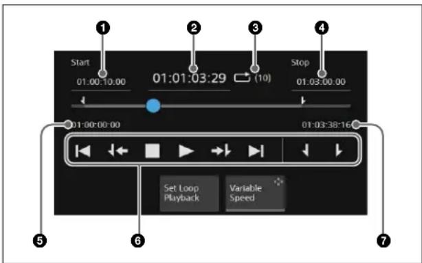
①Play back start point
You can enter a playback start point in the numeric keypad window.
②Current playback position
You can enter a playback position in the numeric keypad window to move to that position.
To set the playback position, set the following parameter.
| No. | Parameter Adjustment | |
| 1 Clip | 1 Current Current | playback position |
③Repeat (loop) playback
When repeat playback is set, a loop icon and the number of repetitions are displayed.
④Playback stop point
You can enter a playback stop point in the numeric keypad window.
⑤Start of video content
⑥Playback operation buttons
| Button Operation | |
 | Move to start of video content |
 | Move to video playback start point |
 | Pause playback |
 | Playback |
 | Move to video playback stop point |
 | Move to end of video content |
| [0x0x0] | Set current position as playback start point |
| [0x0x0] | Set current position as playback stop point |
g End of video content
To play audio
Set the [Audio On] switch to the on state.
To repeat playback (looping)
1 Press the [Set Loop Playback] button.
The [Set Loop Playback] window appears.
2 In the [Loop Mode] group, set repeat playback.
Off: Turns repeat playback off.
Loop: Loop playback. When the playback stop point is reached, playback continues from the playback start point.
When the [Loop] button is selected, set the number of repetitions in the [Repeat] group.
Set the repetitions radio button to the on state, press the input field, and enter the number of repetitions in the numeric keypad window.
To repeat indefinitely, set the [Infinite Loop] radio button to the on state.
3 Press [OK].
To change the playback speed
Set the [Variable Speed] button to the on state and set the following parameter.
| No. | Parameter Adjustment | |
| 2 Clip | 1 Speed Playback | speed (0% to 100%) |
Note
When the [Variable Speed] button is set to the on state, audio is not played.
Playing video (device control block)
The device control block can be switched to device/frame memory/clip player operation mode for playback control of video.
For details about the operation buttons in device/frame memory/clip player operation mode, see “VTR/disk recorder operations” (page 227).
Note
The buttons used for selecting a clip player output channel must be assigned to the device control block beforehand.
For details about assigning buttons, see "Assigning Control Panel Buttons" (page 428).
1 Press the [DEV] button.
The [DEV] button is lit amber, and the operation mode switches to device/frame memory/clip player operation mode.
2 Press the [CLIP1] button.
The [CLIP1] button is lit green, and clip player output channel 1 becomes the target of operations.
When group mode is enabled, the buttons for the two combined clip player output channels are lit.
3 Press the [PLAY] button.
The [PLAY] button is lit amber, and playback starts. To stop playback, press the [STOP], [CUE], [REW], [FF], or [ALL STOP] button.
Video playback operations
Operate using the following buttons.
| Button Operation | |
| FM LOOP Repeat (loop) playback | |
| START TC Set current position as playback start point | |
| STOP TC Set current position as playback stop point | |
| STOP Pause playback | |
| CUE Move to video playback start point | |
| REW Move to start of video content | |
| PLAY | Playback |
| FF | Move to end of video content |
| ALL STOP All stopped | |
Device control block display
In the device control block of the ICP-X7000, the display shows the following information.
- FILE: Name of recalled content
- CRNT: Current playback position timecode (hour:minute:second:frame)
- START: Playback start point timecode (hour:minute:second:frame)
- STOP: Playback stop point timecode (hour:minute:second:frame)
Note
The content name is displayed left-justified in ASCII characters only (up to 20 characters).
Overview
DME function
DME (Digital Multi Effects) allows you to add three-dimensional transforms such as image movement, rotation, magnification and shrinking, as well as special effects.
Multiple DME channels can be also combined, which allows you to create complex and advanced effects.
To use the DME function, the MZS-X1610 3D DME License (option) is required for each target box.
When the system signal format is 2160P, the DME function must be enabled for use.
For details about setting GPU functions, see "Setting a GPU" (page 384).
Enhanced function mode
Depending on the DME effect, an enhanced function DME may be required.
To use an enhanced function DME, set the DME channel to enhanced function mode.
When the system signal format is 2160P, only DME channels 1 and 3 can be set to enhanced function mode. When the system signal format is 1080P, 1080PsF, 1080i, or 720P, only DME channels 1 and 2 can be set to enhanced function mode.
When enhanced function mode is enabled, the number of DME channels that can be used is reduced.
For details about setting enhanced function mode, see "Setting DME Channel Enhanced Function Mode" (page 384).
DME channels
The number of DME channels that can be used will vary, depending on the system signal format, switcher configuration, and enhanced function mode settings.
For details about the number of supported channels, see "Number of Switcher Resources" (page 548).
When the system signal format is 2160P, a box DME can be set for use as DME Ch1/2 or as DME Ch3/4 using the Home > Setup > Switcher > Box Settings > DME/FM Channel Assign menu (19103.53).
For details about assigning a DME channel, see "Setting DME/Frame Memory Channels" (page 425).
If you operate a channel on another box that has the same channel configured, the operation of the boxes is linked.
External input (Ext In)
The signal that is input on DME Ext In (AUX bus output) is set in the Home > Setup > Switcher > DME Interface menu (19103.31) menu.
For details about Ext In settings, see "Setting a DME External Input (Ext In)" (page 417).
Three-Dimensional Transforms
An operation that moves, rotates, or resizes an image in three-dimensional space is called a three-dimensional transform.
Three-dimensional space
Source space and target space
Images are arranged in one of two types of space: source space and target space.
Source space: Three-dimensional space with the image as reference
The X- and Y-axes are defined along the plane of the image, and the Z-axis is defined perpendicular to the plane of the image. When you move an image, the coordinate axes also move.
Target space: Three-dimensional space with the monitor screen as reference
The X- and Y-axes are defined as the horizontal and vertical to the plane of the monitor screen, and the Z-axis is defined perpendicular to the plane of the monitor screen. The coordinate axes do not change even if an image moves.
Source space Target space

Example:
Image moved in X-axis direction
The direction of movement differs as follows in source space and target space.
Source space Target space

Local space and global space
There are two types of DME coordinate space: local space and global space.
Local space: Coordinates that are local to each DME channel
Global space: Coordinates that are common to all channels
By switching from local space to global space, you can add additional movement to the movement of images in individual channels, and also add transform effects to multiple channels that have been combined using global effects.
Example:
Rotation around Y-axis
Rotation around Y-axis in local space
Rotation around Y-axis in global space
Three-dimensional parameters
Three-dimensional parameters have X, Y, and Z values which define the position of an image, its axis of rotation,
the position of the virtual viewpoint of the image, and so on.
On a 16:9 monitor screen, the reference values of parameters for the image (source space) and screen (target space) are as follows.
Center of image or screen:
X = 0.00, Y = 0.00, Z = 0.00
Upper right corner of image or screen:
X = 16.00, Y = 9.00, Z = 0.00
Lower left corner of image or screen:
X = -16.00, Y = -9.00, Z = 0.00

Three-dimensional parameter setting values
The parameter value setting ranges and defaults are as follows.
| Operation Setting range | Default | |
| Move image (Location XYZ) | -999.9999 to +999.999 9 | 0.0000 |
| Rotate image (Rotation) (Spin) | -999.9999 to +999.999 9 | 0.0000 |
| Move rotation axis (Axis Location) | -999.9999 to +999.9999 | 0.0000 |
| Scale image (Location Size) | 0.0000 to 999.9999 1.0000 | |
| Change image aspect ratio (Aspect (X) (Y)) | 0.0000 to 999.9999 1.0000 | |
| Change image aspect ratio (Aspect (Z)) | 0.0000 to 2.0000 1.0000 | |
| Change viewpoint position (Perspective (X) (Y)) | -999.9999 to +999.9999 | 0.0000 |
| Change viewpoint position (Perspective (Z)) | 0.0000 to 999.9999 1.0000 | |
| Change image skew (Skew) | -9.9999 to +9.9999 0.0000 | |
Detents
In three-dimensional space, points called “detents” are defined at regular intervals.
You can set the current three-dimensional parameter values to the closest detent point.
The intervals between detents are defined as follows.
| Operation Detent interval | |
| Move image (Location XYZ) 1.0000 | |
| Rotate image (Rotation) (Spin) 0.1250 | |
| Move rotation axis (Axis Location) 1.0000 | |
| Scale image (Location Size) 0.2500 | |
| Change image aspect ratio (Aspect (X) (Y)) | 0.2500 |
| Change image aspect ratio (Aspect (Z)) | 0.1000 |
| Change viewpoint position (Perspective (X) (Y)) | 1.0000 |
| Change viewpoint position (Perspective (Z)) | 0.0100 |
| Change image skew (Skew) 0.1000 |
Types of Three-Dimensional Transforms
There are the following types of DME three-dimensional transforms.
Move image (Location XYZ)
Moves the image on the X-axis, Y-axis, or Z-axis.
The direction of movement of an image differs depending on whether source space or target space is selected.
Image movement in source space
Movement in X-axis direction
Movement in Y-axis direction
Movement in Z-axis direction
Image movement in target space
Movement in X-axis direction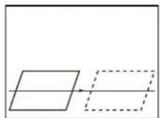
Movement in Y-axis direction
Movement in Z-axis direction
Rotate image (Rotation)
In rotation mode, the image rotates around the X-axis, Y-axis, or Z-axis.
The movement of an image differs depending on whether source space or target space is selected.
Image rotation in source space
Rotation around the X-axis
Rotation around the Y-axis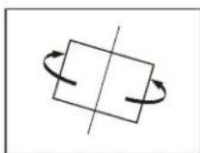
Rotation around the Z-axis
Image rotation in target space
Rotation around the X-axis
Rotation around the Y-axis
Rotation around the Z-axis
Rotate image (Spin)
In spin mode, the image rotates around the X-axis, Y-axis, or Z-axis.
If an image does not rotate correctly around the selected axis in rotation mode, you can combine it with spin mode to create an effect that rotates the image around the selected axis.
The movement of an image differs depending on whether source space or target space is selected. The rotation of an image in source space/target space is the same as in rotation mode.
Move rotation axis (Axis Location)
Moves an axis of rotation of an image in source space.
Movement in X-axis direction
Movement in Y-axis direction
Movement in Z-axis direction
Scale image (Location Size)
Changes the size of the whole image.
Shrinking and magnifying an image in source space is done in three-dimensional space, so magnifying an image enhances perspective.
Shrinking and magnifying an image in target space is a conversion to a two-dimensional image for display on a monitor screen, so shrinking and magnifying does not change the shape of the image.
Scaling in source space
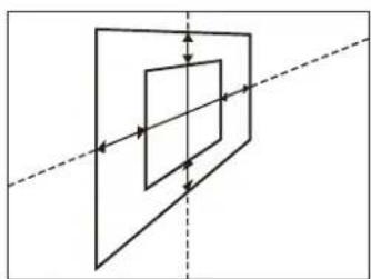
Scaling in target space

Change image aspect ratio (Aspect)
In source space, changes the aspect ratio in the X-axis direction and Y-axis direction, either independently or simultaneously.
Change aspect ratio in X-axis direction
Change aspect ratio in Y-axis direction
Simultaneous change aspect ratio in X-axis direction and Y-axis direction
Change viewpoint position (Perspective)
In target space, changes the perspective of an image by changing the virtual viewpoint, without changing the position of the image.
The X-axis and Y-axis values define the position of the viewpoint, and the Z-axis value defines the distance from the viewpoint.
Change viewpoint position in X-axis direction
Change viewpoint position in Y-axis direction
Change distance from viewpoint position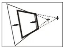
Change image skew (Skew)
In source space, changes the skew of the image in the X-axis direction or Y-axis direction.

Change skew in X-axis direction

Change skew in Y-axis direction
Graphics Display
This function allows you to display wire frames, coordinate axes, and a grid over a DME image. This is useful when checking or modifying an image in three-dimensional space.
For details, see "Graphics Display" (page 213).
DME Effects
The following DME effects can be configured.
Edge effects
Effect Description
Border Add a border to an image.
| Effect Description | |
| Crop Crop the | top, bottom, left, and right of an image. |
| Wipe crop Display | play an image inside or outside a wipe pattern. |
Video modifier effects
| Effect Description |
| Defocus Defocus an image. |
| Sepia Overlay a specified color onto an image. |
| Mono Convert an image to monochrome. |
| Mosaic Divide an image into small tiles. |
| Mask Mask part of an image so that effects are applied to a selected portion. |
Freeze effect
Freeze an image.
Nonlinear effects
| Effect Description |
| Page Turn Turn an image like a turning page. |
| Roll Roll an image like rolled paper or cloth. |
Other settings
Background
Set the signal to insert into the background of an image.
Invert
Invert an image in the horizontal and vertical directions.
Separate Side
Set whether to insert different signals into the front and back sides of the image.
Removing the Virtual Image
When the perspective of an image is changed, this sets the portions beyond the virtual viewpoint displayed on the monitor screen (virtual image) so that they are not displayed.
Key Density
Set the key density.
Key Source
Set the key source signal used for the images on the front and back sides.
Interpolation processing
Set the number of pixels and the anti-aliasing mode used for interpolation processing.
Global Effects
Global effects are effects created by combining multiple consecutive DME channels.
The following global effects can be configured.
| Effect Description | |
| Combiner Combines overlaid images. | |
| Brick Create a rectangular block with three images. | |
| Shadow Add a shadow to an image. |
Three-Dimensional Transforms
Three-dimensional transform operations are performed using the device control block.
You can also adjust three-dimensional parameters using the menu.
Three-Dimensional Transform Operations (Device Control Block)
The illustration shows the ICP-X7000 device control block. The ICP-X1000 series device control block does not have a display.

Three-dimensional transform operation mode
Pressing the [DME] button switches the device control block to three-dimensional transform operation mode. The following buttons are used in three-dimensional transform operation mode.
| Button Description | |
| LOCAL Enable | local space operations.Can be selected at the same time as the [GLB] button. |
| GLB Enable global space operations.Can be selected at the same time as the [LOCAL] button. | |
| SRC Enable source space operations. Cannot be selected at the same time as the [TRGT] button. | |
| TRGT Enable target space operations. Cannot be selected at the same time as the [SRC] button. | |
| ASP PERS • When the [ASP PERS] button is pressed in source space:Adjusts the aspect ratio of an image in the X-axis or Y-axis direction using the trackball, or in both the X-axis and Y-axis directions simultaneously using the Z-ring.When the [ASP PERS] button is pressed while pressing the [SHIFT] button in source space:Adjusts the skew of an image in the X-axis or Y-axis direction using the trackball.When the [ASP PERS] button is pressed in target space:Adjusts the viewpoint position (perspective of an image) in the X-axis or Y-axis direction using the trackball.Adjusts the distance from the viewpoint position using the Z-ring. | |
| LOC SIZE Moves an image in the X-axis or Y-axis direction using the trackball.Scales an image (shrink/magnify) using the Z-ring. | |
| LOC XYZ Moves an image in the X-axis or Y-axis direction using the trackball, and in the Z-axis direction using the Z-ring. | |
| ROT • When the [ROT] button is pressed:Rotates an image around the X-axis or Y-axis using the trackball, and around the Z-axis using the Z-ring.When the [ROT] button is pressed while pressing the [SHIFT] button:Rotates the image in spin mode. | |
| SHIFT Used in combination with the [ASP PERS], [ROT], [CTR], and [CLR WORK BUFR] buttons. | |
| CLR WORK BUFR | • When the [CLR WORK BUFR] button is pressed once:Returns the three-dimensional transform parameters to the initial settings.When the [CLR WORK BUFR] button is pressed twice, or the [CLR WORK BUFR] button is pressed once while pressing the [SHIFT] button:Returns all DME parameters to the initial settings. |
| AXIS LOC | Moves the rotation axis of an image in the X-axis or Y-axis direction using the trackball, and in the Z-axis direction using the Z-ring. |
| Button Description | |
| X | Restricts the parameters targeted by the operation. |
| Y | You can select multiple buttons. |
| Z | When the [X] button is lit:Operations on parameters on the X-axis using the trackball are enabled.When the [Y] button is lit:Operations on parameters on the Y-axis using the trackball are enabled.When the [Z] button is lit:Operations on parameters on the Z-axis (Z-ring adjustment items) using the Z-ring are enabled. |
| FINE Switches | to fine mode, enabling fine adjustment control of setting values using the trackball and Z-ring. |
| CTR • When the [CTR] button is pressed once:Adjusts the three-dimensional transform parameters to the detent positions.When the [CTR] button is pressed twice, or the [CTR] button is pressed once while pressing the [SHIFT] button:Returns the three-dimensional transform parameters to the default values. | |
Trackball and Z-ring operations
Operation in the X-axis direction:
Turn the trackball horizontally.
Parameter values increase as you turn to the right, and decrease as you turn to the left.

Operation in the Y-axis direction:
Turn the trackball vertically.
Parameter values increase as you turn upward, and decrease as you turn downward.

Operation in the Z-axis direction:
Turn the Z-ring.
Parameter values increase as you turn clockwise, and decrease as you turn counterclockwise.
However, if you have pressed the [LOC XYZ] button or [AXIS LOC] button, the parameter values decrease as
you turn clockwise, and increase as you turn counterclockwise.

Transforming an image using trackball/Z-ring operations
You can transform an image as follows using trackball/Z-ring operations for each three-dimensional transform.
| Button | Three-dimensional space | Trackball Z-ring | ||
| Horizontal direction | Vertical direction | |||
| LOC XYZ | Source/target space | Movement in X-axis direction | Movement in Y-axis direction | Movement in Z-axis direction |
| ROT Source/target space | Rotation around Y-axis | Rotation around X-axis | Rotation around Z-axis | |
| SHIFT + ROT | Source/target space | Rotation around Y-axis (Spin) | Rotation around X-axis (Spin) | Rotation around Z-axis (Spin) |
| AXIS LOC | Source space | Move rotation axis in X-axis direction | Move rotation axis in Y-axis direction | Move rotation axis in Z-axis direction |
| LOC SIZE | Source/target space | Movement in X-axis direction | Movement in Y-axis direction | Scaling (shrink/ magnify) |
| ASPPERS | Source space | Change aspect ratio in X-axis direction | Change aspect ratio in Y-axis direction | Simultaneous change aspect ratio in X-axis direction and Y-axis direction |
| Target space | Change viewpoint position in X-axis direction | Change viewpoint position in Y-axis direction | Change distance from viewpoint position | |
| SHIFT + ASP PERS | Source space | Change skew in X-axis direction (Skew) | Change skew in Y-axis direction (Skew) | Simultaneous change aspect ratio in X-axis direction and Y-axis direction |
Device control block display
In the device control block of the ICP-X7000, the display shows the following information.
• Reference DME channel name: DME1 to DME4
- Selected three-dimensional space: LOCAL, GLB and SRC, TRGT
- Selected parameter name: ASP PERS, LOC SIZE, LOC XYZ, ROT, AXIS LOC, SPIN, SKEW • X-axis, Y-axis, and Z-axis settings
Transforming an image in three-dimensional space
1 Press the [DME] button.
The [DME] button is lit amber, and the device control block switches to three-dimensional transform operation mode.
2 Using the channel selection buttons, select the target channel (CH1 to CH4) for operation.
You can select multiple channels. The first selected button becomes the reference channel, and is lit green. Subsequent selected buttons are lit amber.
3 Select a three-dimensional space.
[LOCAL] button: Local space
[GLB] button: Global space
Both local space and global space can be selected.
[SRC] button: Source space
[TRGT] button: Target space
Either source space or target space can be selected.
4 Select a three-dimensional transform operation and transform the image.
For details about three-dimensional transform operations, see “Three-dimensional transform operation mode” (page 209).
To finely adjust the setting values of parameters, press the [FINE] button to turn it on.
The adjustment mode switches to fine mode, enabling fine adjustment of setting values using the trackball/Z-ring.
To restrict the parameters targeted by the operation
Press the [X] button, [Y] button, or [Z] button, turning it on.
This enables operation only for the selected axis using the trackball/Z-ring.
To adjust the setting values of parameters using the numeric keypad control block
You can press the [X] button, [Y] button, or [Z] button in the device control block to display the name and value of parameters on the display of the numeric keypad control block and then set the X-axis, Y-axis, and Z-axis parameters. Enter a value in the numeric keypad area and press the [ENTER] button to apply the setting.
Note
You can also enter a difference value from the currently set value using the [TRIM] button.
For details, see “Entering a difference from a current value” (page 88).
To change parameters to the closest detent position
Press the [CTR] button once.
For details about detents, see "Detents" (page 206).
To return the parameters to the default values
Press the [CTR] button twice. Or press and hold the [SHIFT] button and press the [CTR] button.
For details about default values, see "Three-dimensional parameter setting values" (page 205).
To return parameters to the initial settings
The parameters return to the initial status saved data setting values.
The operation must be performed separately for global space and local space.
For details about initial status, see "Setting Startup" (page 379).
To return three-dimensional parameters to the initial settings:
Press the [CLR WORK BUFR] button once.
To return all DME parameters to the initial settings: Press the [CLR WORK BUFR] button twice. Or press and hold the [SHIFT] button and press the [CLR WORK BUFR] button.
Three-Dimensional Transform Operations (Menu)
This section describes the menu for DME channel 1 as an example.
Adjusting three-dimensional parameters
1 Open the Home > DME > Channel1 > 3D Transform > Adjust menu (15101.11).
2 In the [Local/Global] group, select local space or global space.
Local: Local space
Global: Global space
Both local space and global space can be selected.
3 In the [Source/Target] group, select source space or target space.
Source: Source space
Target: Target space
Either source space or target space can be selected.
4 Set the target three-dimensional transform operation X-axis, Y-axis, and Z-axis parameters.
When local space is selected
Press the [X] button, [Y] button, or [Z] button for [Local], and enter a setting value in the numeric keypad window.
When global space is selected
Press the [X] button, [Y] button, or [Z] button for [Global], and enter a setting value in the numeric keypad window.
To adjust parameters using the analog controls section
Press the button for the target three-dimensional transform operation to set, and set the [X] parameter, [Y] parameter, and [Z] parameter in the analog controls section.
When both local space and global space are selected, the parameter buttons for local space are displayed on the 1st page and the parameter buttons for global space are displayed on the 2nd page. Set the parameters for local space on the 1st page and the parameters for global space on the 2nd page.
Configurable three-dimensional parameters
The parameters that can be set vary depending on the three-dimensional transform operation buttons.
Location Size: Scale image (shrink/magnify) Only the Z-axis in source space can be configured. All axes in target space can be configured.
Location XYZ: Move image
All axes can be configured.
Rotation: Rotate image (rotation mode) All axes can be configured.
Spin: Rotate image (spin mode) All axes can be configured.
Aspect: Change image aspect ratio Only the source space of the local space can be configured.
Skew: Change image skew Only the X-axis and Y-axis in the source space of the local space can be configured.
Perspective: Change viewpoint position Only target space can be configured.
Axis Location: Move rotation axis Only source space can be configured.
To change parameters to the closest detent position
Press the [Detents] button.
For details about detents, see "Detents" (page 206).
To return parameters to the initial settings
The parameters return to the initial status saved data setting values.
The operation must be performed separately for global space and local space.
For details about initial status, see "Setting Startup" (page 379).
To return three-dimensional parameters to the initial settings:
Press the [Clear 3D Parameter] button.
To return all DME parameters to the initial settings:
Press the [Clear All Parameters] button.
Graphics Display
Overview
This function allows you to display wire frames, coordinate axes, and a grid over a DME image.
You can configure the following kinds of graphics.
Note
Do not use the graphics display function while on-air, as images in a DME, clip player, or multi viewer may become distorted while in use.
Wire frame
Places a wire frame around the image. This allows you to check the position and size of the image.
Note
When a Shadow global effect is set, a shadow frame is displayed.
Coordinate axes
Displays three-dimensional coordinates in local space or global space. This allows you to check the origin and the directions of the X-axis, Y-axis, and Z-axis.
Channel ID
Displays the channel number. This allows you to check the channel being used.
Channel IDs are displayed differently in local space and global space.
Local space: The channel number is displayed along with "F" (Front) or "B" (Back) indicating the side of the wire frame. For example, "1F" indicates that channel 1 is being used at the front in local space.
Global space: The channel number is displayed along with "G" (Global) to indicate global space. For example, "G2" indicates that channel 2 is being used in global space.
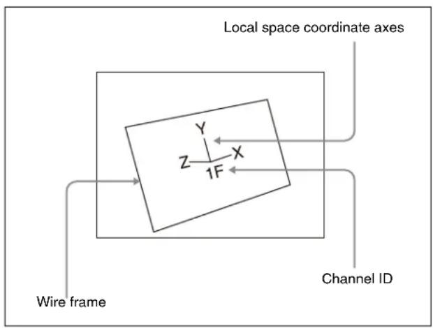
Grid
Displays a grid on the monitor screen. It is enabled when setting the position of an image in two-dimensional space.

Scale (reduced display)
The size is reduced to display the range that is not displayed on the normal monitor screen. This allows you to check the position of an image in a larger space. The range displayed on a normal monitor screen is indicated by a frame.
![graph TD A["Range displayed on normal monitor screen"] --> B["Switch Symbol"] B --> C["Wire frame"]](/content/2026/06/1382172/images/cadfe4166ee6f132295cb5ec88b4fba77c5296a8078abe219448ec577763647e.jpg)
Automatically erasing the graphics display
This automatically erases the graphics display when an effect timeline is executed. You can set the timing for when to redisplay graphics after the effect timeline has completed.
Setting a Graphic
This section describes the menu for DME channel 1 as an example.
1 Open the Home > DME > Channel1 > Input/Output > Graphic menu (15101.04). 2 Set the [Graphic] button to the on state. 3 In the [Graphic Type] group, select a type of graphic.
Axis: Coordinate axes
Axis Name: Axis names
Ch ID: Channel ID
Wire Frame: Wire frame
Grid: Grid
To reduce the display size of graphics display
Set the [Scale] button to the on state and set the following parameter.
| No. | Parameter Adjustment | |
| 1 | Scale | Degree of scale reduction |
To automatically erase the graphics display when an effect timeline is executed
Set the [Auto Erase] button to the on state and set the following parameter.
| No. | Parameter Adjustment |
| 1 | Recover Time Time for redisplaying graphics after an effect timeline has completed |
Edge Effects
This section describes the menu for DME channel 1 as an example.
Setting a Border
1 Open the Home > DME > Channel1 > Edge > Border/Crop menu (15101.21).
2 Set the [Border] button to the on state and set the following parameters.
| No. | Parameter Adjustment | |
| 1-1 H | Simultaneous adjustment of border width of left and right edges | |
| 1-2 V | Simultaneous adjustment of border width of top and bottom edges | |
| 1-3 All | Simultaneous adjustment of border width of top, bottom, left, and right edges | |
| 1-5 Density Density of border a) | ||
| 2-1 Top Border width of top edge | ||
| 2-2 Left Border width of left edge | ||
| 2-3 Right Border width of right edge | ||
| 2-4 Bottom Border width of bottom edge | ||
| 2-5 Density Density of border a) | ||
a) The |Density| parameter in numbers 1-5 and 2-5 are common.
3 In the [Border Fill] group, select a signal to insert in the border.
Flat Color: Single color
Ext Video: External input (Ext In) signal
When the [Flat Color] button is selected, set the following parameters.
| No. | Parameter Adjustment | |
| 1 | Luminance Luminance | |
| 2 | Saturation | Saturation |
| 3 | Hue | Hue |
To soften the border
Set the [Border Soft] button to the on state and set the following parameter.
| No. | Parameter Adjustment | |
| 1 | Soft | Softness of inner edge of border |
Setting a Crop
1 Open the Home > DME > Channel1 > Edge > Border/Crop menu (15101.21).
2 Set the [Crop] button to the on state and set the following parameters.
| No. | Parameter Adjustment | |
| 1-1 H | Simultaneous adjustment of crop of left and right edges a) | |
| 1-2 V | Simultaneous adjustment of crop of top and bottom edges a) | |
| 1-3 All | Simultaneous adjustment of crop of top, bottom, left, and right edges a) | |
| 2-1 Top Crop of top edge | ||
| 2-2 Left Crop of left edge | ||
| 2-3 Right Crop of right edge | ||
| 2-4 Bottom Crop of bottom edge | ||
a) The entered numeric value is automatically a positive value for the right and top edges and a negative value for the left and bottom edges.
To soften the edges
Set the [Edge Soft] button to the on state and set the following parameter.
| No. | Parameter Adjustment | |
| 1 Soft | Edge softness | |
Linking the crop areas when inverting
1 Open the Home > DME > Channel1 > Edge > Border/Crop menu (15101.21).
2 In the [Invert/Crop Process] group, select the operation when inverting.
Crop -> Invert: With the axis of symmetry at the center of the input image, invert both the central image and the crop area horizontally and vertically around the axis of symmetry. The order of effect application for the input image is Crop and then Invert.
Invert -> Crop: With the axis of symmetry at the center of the input image, invert only the central image horizontally and vertically around the axis of symmetry. The order of effect application is Invert and then Crop.
Setting a Wipe Crop
Note
When Brick is set, Wipe Crop cannot be enabled.
1 Open the Home > DME > Channel1 > Edge > Wipe Crop menu (15101.22). 2 Set the [Wipe Crop] button to the on state. 3 Press the [Pattern Select] button.
A pattern selection window appears.
4 Set the button for the target wipe crop pattern to the on state.
Note
The wipe crop patterns are the same as wipe pattern numbers 1 to 24 and 304.
5 Press [OK].
To invert the wipe crop area (Invert)
You can swap the inner and outer areas of the wipe crop pattern.
Set the [Invert] button to the on state.
To set the radius of wipe crop pattern corners (Radius)
You can set the radius of the four corners when pattern number 304 is selected.
Set the [Radius] button to the on state and set the following parameter.
| No. | Parameter Adjustment |
| 1 Radius | Corner radius |
To replicate a wipe crop pattern (Multi)
You can replicate a pattern horizontally, vertically, or both up to 63 times.
For details about pattern layouts, see “Replicating a wipe pattern (Multi)” (page 169).
Set the [Multi] button to the on state and set the following parameters.
| No. | Parameter Adjustment |
| 1 H | Multi Number of repetitions of pattern horizontally |
| 2 V | Multi Number of repetitions of pattern vertically |
| 3 Invert | Type Pattern layout (1 to 4) |
To set the wipe crop pattern position and size (Position/Size)
Set the [Position/Size] button to the on state and set the following parameters.
| No. | Parameter Adjustment |
| 1 H | Horizontal position |
| 2 V | Vertical position |
| 3 Size | Pattern size |
| 5 Pattern | Pattern number (1 to 24, 304) |
To set the aspect ratio of a wipe crop pattern (Aspect)
Set the [Aspect] button to the on state and set the following parameter.
| No. | Parameter Adjustment |
| 1 Aspect | Aspect ratioNegative values expand vertically.Positive values expand horizontally. |
To rotate a wipe crop pattern (Rotation)
In the [Rotation] group, select a rotation type.
Angle: Incline a pattern at a fixed angle.
Speed: Rotate a pattern at a fixed speed.
When the [Angle] button is selected, set the following parameter.
| No. | Parameter Adjustment |
| 1 | Angle Inclination angle of patternA value of -1.00 corresponds to a rotation of one turn counterclockwise.A value of +1.00 corresponds to a rotation of one turn clockwise.A value of 0.00 corresponds to no rotation. |
When the [Speed] button is selected, set the following parameter.
| No. | Parameter Adjustment |
| 1 | Speed Rotation speed of patternA value of -100.00 corresponds to 4 revolutions/second counterclockwise rotation.A value of +100.00 corresponds to 4 revolutions/second clockwise rotation.A value of 0.00 corresponds to no rotation (stationary). |
To add modulation to a wipe crop pattern (Modulation)
In the [Modulation] group, select a modulation type.
H: Modulate a pattern in the horizontal direction.
V: Modulate a pattern in the vertical direction.
Set the following parameters.
| No. | Parameter Adjustment |
| 1 | Amplitude Amplitude of modulation |
| 2 | Frequency Frequency of modulation |
| 3 | Speed Speed of ripplesNegative values create waves in the down and left directions.Positive values create waves in the up and right directions. |
To modify a wipe crop pattern edge (Edge)
1 In the [Edge] group, select a type of edge.
Border: Adds a border to a pattern.
Soft: Softens the edges of a pattern.
Soft Border: Softens a border applied to a pattern.
When the [Border] button is selected, set the following parameter.
| No. | Parameter Adjustment |
| 1 Width | Border width |
When the [Soft] button is selected, set the following parameter.
| No. | Parameter Adjustment | |
| 1 Soft | Edge softness |
When the [Soft Border] button is selected, set the following parameters.
| No. | Parameter Adjustment | |
| 1 | Width | Border width |
| 2 | Inner | Soft Softness of inner edge of border |
| 3 | Outer | Soft Softness of outer edge of border |
2 In the [Border Fill] group, select a signal to insert in the border.
Flat Color: Single color
Ext Video: External input (Ext In) signal When the [Flat Color] button is selected, set the following parameters.
| No. | Parameter Adjustment |
| 1 | Luminance Luminance |
| 2 | Saturation Saturation |
| 3 | Hue |
Video Modifier Effects
This section describes the menu for DME channel 1 as an example.
Setting Defocus
Note
To use the Defocus effect, the DME channel must be set to enhanced function mode.
1 Open the Home > DME > Channel1 > Video Modify > Defocus menu (15101.31). 2 Set the [Defocus] button to the on state and set the following parameters.
| No. | Parameter Adjustment |
| 1 H | Defocusing in horizontal direction |
| 2 V | Defocusing in vertical direction |
| 3 All | Simultaneous defocusing adjustment in horizontal direction and vertical direction |
3 In the [Defocus Mode] group, select a signal to which to apply the Defocus effect.
Video/Key: Video signal and key signal
Video: Video signal only
To remove the black level leakage that occurs at the edges of the screen
Set the [Clean Defocus] button to the on state.
Setting Sepia
Note
Enabling Sepia disables Mono if it is set.
1 Open the Home > DME > Channel1 > Video Modify > Color Modify menu (15101.32). 2 Set the [Sepia] button to the on state and set the following parameters.
| No. | Parameter Adjustment | |
| 1 | Mix Y | Luminance signal mix amount |
| 2 Mix | C Chrominance signal mix amount | |
| 3 Mix | All Simultaneous adjustment of luminance signal and chrominance signal mix amounts | |
3 Press the [Sepia Color] button and set the sepia color using the following parameters.
| No. | Parameter Adjustment |
| 1 | Luminance Luminance |
| 2 | Saturation Saturation |
| 3 | Hue |
Setting Mono
Note
Enabling Mono disables Sepia if it is set.
1 Open the Home > DME > Channel1 > Video Modify > Color Modify menu (15101.32). 2 Set the [Mono] button to the on state.
Setting a Mosaic
1 Open the Home > DME > Channel1 > Video Modify > Mosaic menu (15101.33). 2 Set the [Mosaic] button to the on state and set the following parameters.
| No. | Parameter Adjustment |
| 1 Size | Tile size |
| 2 Aspect | Tile aspect ratioNegative values expand vertically.Positive values expand horizontally. |
Setting a Mask
You can mask out part of a Defocus, Sepia, Mono, or Mosaic effect.
Separate masks can be set for group 1 effects (Sepia,
Mono, Mosaic) and group 2 effects (Defocus).
Note
If a border has been set and then masks are enabled on both group 1 effects and group 2 effects, the Border effect will also be masked.
1 Open the Home > DME > Channel1 > Video Modify > Mask menu (15101.34). 2 In [Effect Group], set the [Mask] switch for the target effect to the on state.
Group 1: Sepia, Mono, and Mosaic effects
Group 2: Defocus effect
3 Press the [Position/Size] button and set the mask pattern using the following parameters.
| No. | Parameter Adjustment | |
| 1 H Horizontal position | ||
| 2 V Vertical position | ||
| 3 Size | Size | |
| 4 Soft | Softness | |
| 5 | Pattern | Pattern number (21, 24, 304) |
Note
The mask patterns are the same as wipe pattern numbers 21, 24, and 304.
To set the aspect ratio of a mask pattern (Aspect)
Press the [Aspect] button and set the following parameter.
| No. | Parameter Adjustment |
| 1 | Aspect Aspect ratioNegative values expand vertically.Positive values expand horizontally. |
To rotate a mask pattern
In the [Rotation] group, select a rotation type.
Angle: Incline a pattern at a fixed angle.
Speed: Rotate a pattern at a fixed speed.
When the [Angle] button is selected, set the following parameter.
| No. | Parameter Adjustment |
| 1 | Angle Inclination angle of patternA value of -1.00 corresponds to a rotation of one turn counterclockwise.A value of +1.00 corresponds to a rotation of one turn clockwise.A value of 0.00 corresponds to no rotation. |
When the [Speed] button is selected, set the following parameter.
| No. | Parameter Adjustment |
| 1 | Speed Rotation speed of patternA value of -100.00 corresponds to 4 revolutions/second counterclockwise rotation.A value of +100.00 corresponds to 4 revolutions/second clockwise rotation.A value of 0.00 corresponds to no rotation (stationary). |
To invert a mask area
Set the [Invert] button to the on state.
Freeze Effects
The following three types of freeze effects can be set. Hard freeze: Generate a still image at an arbitrary position.
Time strobe: Generate still images at fixed intervals. Film: Generate frames like in movie films. This section describes the menu for DME channel 1 as an example.
Note
When the system signal format is 1080PsF or 720P, Film cannot be set.
Setting a Freeze
1 Open the Home > DME > Channel1 > Freeze menu (15101.41).
2 In the [Freeze] group, select a type of freeze.
Hard Freeze: Hard freeze
Time Strobe: Time strobe
Film: Film
When the [Time Strobe] button is selected, set the following parameters.
| No. | Parameter Adjustment | |
| 1 | Duration Freeze interval | |
| 2 | Live Percentage of video time between still images | |
When the [Film] button is selected, set the following parameter.
| No. | Parameter Adjustment | |
| 1 | Film | Frame rate |
Note
When the system signal format is 1080PsF or 720P, the [Film] button is grayed out and cannot be changed.
Nonlinear Effects
It is not possible to apply two or more nonlinear effects at the same time. Enabling an effect automatically disables the previously enabled effect.
This section describes the menu for DME channel 1 as an example.
Setting a Nonlinear Effect
Select a type of nonlinear effect to enable.
1 Open the Home > DME > Channel1 > Non Linear > Effect List menu (15101.51). 2 Press the button for the nonlinear effect to enable.
The setup menu for the selected nonlinear effect appears and nonlinear effects become enabled.
To disable nonlinear effects
Press the [Off] button.
Setting a Page Turn
In the Home > DME > Channel1 > Non Linear > Effect List menu (15101.51), press the [Page Turn] button to display the Home > DME > Channel1 > Non Linear > Page Turn menu (15101.52).
In the Home > DME > Channel1 > Non Linear > Page Turn menu (15101.52), set the [Page Turn] button to the on state and set the following parameters.
| No. | Parameter Adjustment |
| 1 | Radius Radius of the turned page flap |
| 2 | Offset Amount of page turn |
| 3 | Angle Angle of page turn |
To split an image
In the [Split Mode] group, select a type of split.
H&V: Split horizontally and vertically (top, bottom, left, right)
H: Split horizontally (left, right)
V: Split vertically (top, bottom)
To select a signal to insert on the back side of the page
In the [Back Video] group, select a signal.
Self: Same signal as the front side
Flat: Single color
Hue Rotation: Gradually varying hue
2nd Channel: 2nd channel signal
When the [Flat] button is selected, set the following parameters.
| No. | Parameter Adjustment | |
| 1 | Luminance Luminance | |
| 2 | Saturation Saturation | |
| 3 | Hue | Hue |
When the [Hue Rotation] button is selected, set the following parameters.
| No. | Parameter Adjustment |
| 1 | Luminance Luminance |
| 2 | Saturation Saturation |
| 3 | Speed Speed at which the hue changes |
Note
To set a 2nd channel signal, a DME channel for the second channel must be selected beforehand.
For details about selecting a DME channel, see “DME Effects for Keys” (page 144).
Setting a Roll
In the Home > DME > Channel1 > Non Linear > Effect List menu (15101.51), press the [Roll] button to display the Home > DME > Channel1 > Non Linear > Roll menu (15101.53).
In the Home > DME > Channel1 > Non Linear > Roll menu (15101.53), set the [Roll] button to the on state and set the following parameters.
| No. | Parameter Adjustment |
| 1 | Radius Radius of the rolled portion |
| 2 | Offset Amount of roll |
| 3 | Angle Angle of roll |
To split an image
In the [Split Mode] group, select a type of split.
H&V: Split horizontally and vertically (top, bottom, left, right)
H: Split horizontally (left, right)
V: Split vertically (top, bottom)
To select a signal to insert on the back side of the roll
In the [Back Video] group, select a signal.
Self: Same signal as the front side
Flat: Single color
Hue Rotation: Gradually varying hue
2nd Channel: 2nd channel signal
When the [Flat] button is selected, set the following parameters.
| No. | Parameter Adjustment |
| 1 | Luminance Luminance |
| 2 | Saturation Saturation |
| 3 | Hue |
When the [Hue Rotation] button is selected, set the following parameters.
| No. | Parameter Adjustment |
| 1 | Luminance Luminance |
| 2 | Saturation Saturation |
| 3 | Speed Speed at which the hue changes |
Note
To set a 2nd channel signal, a DME channel for the second channel must be selected beforehand.
For details about selecting a DME channel, see “DME Effects for Keys” (page 144).
Other Settings
This section describes the menu for DME channel 1 as an example.
Setting a Background
You can select a signal to insert into the background of an image.
1 Open the Home > DME > Channel1 > Input/Output > Bkgd menu (15101.01).
2 In the [Border Fill] group, select a signal to insert in the border.
Flat Color: Single color Ext Video: External input (Ext In) signal When the [Flat Color] button is selected, set the following parameters.
| No. | Parameter Adjustment |
| 1 | Luminance Luminance |
| 2 | Saturation Saturation |
| 3 | Hue |
Setting Inversion (Invert)
You can invert the video signal/key signal of an image horizontally and vertically.
1 Open the Home > DME > Channel1 > Input/Output > Video/Key menu (15101.02).
2 In the [Front] group, select the direction of inversion for the image on the front side.
H Invert: Invert horizontally. V Invert: Invert vertically.
3 In the [Back] group, select the direction of inversion for the image on the back side.
H Invert: Invert horizontally. V Invert: Invert vertically.
Setting Separate Sides
You can insert a different video signal/key signal into the front and back sides of the image by enabling separate sides.
1 Open the Home > DME > Channel1 > Input/Output > Video/Key menu (15101.02). 2 Set the [Separate Side] button to the on state.
Removing the Virtual Image
When the perspective of an image is changed, portions beyond the virtual viewpoint may be displayed wrapped around on the monitor screen (virtual image). You can make a setting so the virtual image portions are not displayed.
1 Open the Home > DME > Channel1 > Input/Output > Video/Key menu (15101.02). 2 Set the [Wrap Around] button to the on state.
The virtual image portions are removed.
Setting Key Density
You can set the key density.
1 Open the Home > DME > Channel1 > Input/Output > Video/Key menu (15101.02). 2 Set the [Key Density] button to the on state and set the following parameter.
| No. | Parameter Adjustment |
| 1 Key | Density Key density |
Setting a Key Source Signal
You can select a key source signal used for the images on the front and back sides.
1 Open the Home > DME > Channel1 > Input/Output > Video/Key menu (15101.02). 2 In the [Front Key] group, select a key source signal for the image on the front side.
Ext Key: Key signal sent from the switcher
Int Key: DME internal key signal
Linear Key: Luminance signal of the input video signal
When the [Linear Key] button is selected, set the following parameters.
| No. | Parameter Adjustment | |
| 1 | Clip | Reference level for key signal generation |
| No. | Parameter Adjustment | |
| 2 Gain | Key gain |
Note
If a DME channel is assigned as the 1st channel, only the [Ext Key] button can be selected.
3 In the [Back Key] group, select a key source signal for the image on the back side.
Ext Key: Key signal sent from the switcher
Int Key: DME internal key signal
Linear Key: Luminance signal of the input video signal
When the [Linear Key] button is selected, set the following parameters.
| No. | Parameter Adjustment | |
| 1 Clip | Reference level for key signal generation | |
| 2 Gain | Key gain | |
Note
If a DME channel is assigned as the 1st channel, only the [Ext Key] button can be selected.
Setting Interpolation Processing
You can set the number of pixels and the anti-aliasing mode used for interpolation processing.
1 Open the Home > DME > Channel1 > Input/Output > Process menu (15101.03). 2 In the [Interpolation Mode] group, set the number of pixels to use in interpolation.
Multi: Use multi-point interpolation.
Linear: Use two-point interpolation.
Note
The [Multi] button can be selected only when the DME channel is set to enhanced function mode.
3 In the [Filter Mode] group, select an anti-aliasing mode.
Model1: Even when the picture is reduced, add compensation so that it can be seen clearly (standard).
Mode2: Suppress aliasing when enlarging or reducing the picture (soft).
Mode3: Do not suppress aliasing when enlarging or reducing the picture (sharp).
Global Effects
Overview
Global effects are effects created by combining multiple consecutive DME channels.
The following global effects can be configured.
- Combiner
- Brick
- Shadow
Setting a Combiner
Images selected on multiple DME channels can be combined automatically. You can set the order of priority (1 to 4) for combining images from up to four channels. The selected channels (Ch1 to Ch4) are assigned to combiners 1 and 2 as follows.
| Channel Combiner 1 | Combiner 2 | |
| Ch1 + Ch2 Ch1, Ch2 – | ||
| Ch2 + Ch3 Ch2, Ch3 – | ||
| Ch3 + Ch4 Ch3, Ch4 – | ||
| Ch1 + Ch2, Ch3 + Ch4 | Ch1, Ch2 Ch3, Ch4 | |
| Ch1 + Ch2 + Ch3 Ch1, | Ch2, Ch3 – | |
| Ch2 + Ch3 + Ch4 Ch2, | Ch3, Ch4 – | |
| Ch1 + Ch2 + Ch3 + Ch4 | Ch1, Ch2, Ch3, Ch4 | – |
1 Open the Home > DME > Global Effect > Combiner Priority menu (15109.11). 2 In the [Combiner 1 Priority] group, set the priority order.
When combining two channels
Set the channel buttons to the on state using [Priority 1] and [Priority 2].
When combining three channels
Set the channel buttons to the on state using [Priority 1] to [Priority 3].
When combining four channels
Set the channel buttons to the on state using [Priority 1] to [Priority 4].
When combining Ch1 + Ch2 and Ch3 + Ch4
In the [Combiner 1 Priority] group, set the priority order for channels 1 and 2. In the [Combiner 2 Priority] group, set the priority order for channels 3 and 4.
Setting a Brick
Images selected on three DME channels can be combined into a brick shape.

The selected channels (Ch1 to Ch4) are assigned to the surfaces of the brick as follows.
| Channel | Top side | Side V | Side H |
| Ch1 + Ch2 + Ch3 | Ch1 Ch2 Ch3 | ||
| Ch2 + Ch3 + Ch4 | Ch2 Ch3 Ch4 |
Note
When the system signal format is 2160P, Brick cannot be set.
1 Open the Home > DME > Global Effect > Brick menu (15109.21). 2 Set the [Brick] button to the on state and set the following parameters.
| No. | Parameter | Adjustment |
| 1 | Height | Height of brick |
| 2 | Front Overlap | Front overlap |
| 3 | Side H Overlap | Side H overlap |
| 4 | Side V Overlap | Side V overlap |
3 In the [Side H] group, select how to fit the image on side H.
Crop: Crop the parts that do not fit into the side without shrinking the picture.
Compress: Reduce the image to fit.
When the [Crop] button is selected, set the following parameters.
The position of the image set by the parameters is the top left of side H. The bottom right is set automatically.
| No. | Parameter | Adjustment |
| 1 | H | Position of left edge |
| 2 | V | Position of top edge |
When the [Compress] button is selected, set the following parameters.
The image with ranges set by the parameters is enlarged/reduced to match the size of side H.
| No. | Parameter Adjustment |
| 1 | Top Position of top edge |
| 2 | Left Position of left edge |
| 3 | Right Position of right edge |
| 4 | Bottom Position of bottom edge |
4 In the [Side H Rotation] group, set the angle of rotation of the image on side H.
0: No rotation
90: 90° rotation
180: 180° rotation
270: 270° rotation
5 In the [Side V] group, select how to fit the image on side V.
Configure in the same way as for side H.
6 In the [Side V Rotation] group, set the angle of rotation of the image on side V.
Configure in the same way as for side H.
To invert the image on the front side
In the [Side H Front] group for side H or [Side V Front] group for side V, select the direction of inversion.
Invert H: Invert horizontally.
Invert V: Invert vertically.
To invert the image on the back side
In the [Side H Back] group for side H or [Side V Back] group for side V, select the direction of inversion.
Invert H: Invert horizontally.
Invert V: Invert vertically.
Setting a Shadow
You can add a shadow to the image using two DME channels.
The channel with the higher number from among the two channels is used as the shadow.
The following channels can be used as the shadow, depending on which channels (Ch1 to Ch4) are combined.
O: Shadow can be set
| Channel Shadow setting | |||||
| Ch1 | Ch2 | Ch3 | Ch1 + | Ch2 Ch2 + Ch3 | |
| Ch1 + Ch2 | - - - - - | ||||
| Ch2 + Ch3 | - - - - - - | ||||
| Ch3 + Ch4 | - - - - - - - | ||||
| Ch1 + Ch2,Ch3 + Ch4 | - - - - | ||||
| Channel Shadow setting | |||||
| Ch1 | Ch2 | Ch3 | Ch1 + | Ch2 Ch2 + Ch3 | |
| Ch1 + Ch2 + Ch3 | - | - | |||
| Ch2 + Ch3 + Ch4 | - - | ||||
| Ch1 + Ch2 + Ch3 + Ch4 | - | ||||
This section describes setting a shadow on channel 1 as an example.
1 Open the Home > DME > Global Effect > Shadow menu (15109.31).
2 Set the [Ch 1 Shadow] button to the on state and set the following parameters.
| No. | Parameter Adjustment | |
| 1 | Position H | Shadow position in the horizontal direction |
| 2 | Position V | Shadow position in the vertical direction |
| 3 Density | Density of shadow | |
3 In the [Ch 1 Shadow Source] group, select a signal to insert in the shadow.
Video: Channel 2 input video signal
Flat Color: Single color
When the [Flat Color] button is selected, set the following parameters.
| No. | Parameter Adjustment | |
| 1 | Luminance | Luminance |
| 2 | Saturation | Saturation |
| 3 | Hue | Hue |
To set a shadow on a channel other than channel 1, do the following.
To set a shadow on channel 2:
Set using the [Ch 2 Shadow] button and [Ch 2
Shadow Source] group.
Channel 3 is used as the shadow.
To set a shadow on channel 3:
Set using the [Ch 3 Shadow] button and [Ch 3
Shadow Source] group.
Channel 4 is used as the shadow.
Setting a shadow using channels 1 to 3 (Ch1 + Ch2 + Ch3)
Set a “Ch1 + Ch2 + Ch3” combine, set the [Ch 1 + Ch 2
Shadow] button to the on state, and perform the following.
To set a shadow on channel 1 for the background for the images on channels 1 and 3:
Set the [Ch 1 Shadow] button to the on state.
To set a shadow on channel 2 for the background for the images on channels 1 and 2:
Set the [Ch 2 Shadow] button to the on state.
Setting a shadow using channels 2 to 4 (Ch2 + Ch3 + Ch4)
Set a “Ch2 + Ch3 + Ch4” combine, set the [Ch 2 + Ch 3 Shadow] button to the on state, and perform the following.
To set a shadow on channel 2 for the background for the images on channels 2 and 4:
Set the [Ch 2 Shadow] button to the on state.
To set a shadow on channel 3 for the background for the images on channels 2 and 3:
Set the [Ch 3 Shadow] button to the on state.
Setting a shadow using channels 1 to 4 (Ch1 + Ch2 + Ch3 + Ch4)
Set a “Ch1 + Ch2 + Ch3 + Ch4” combine, set the [Ch 1 + Ch 2 Shadow] button to the on state, and perform the following.
To set a shadow on channel 1 for the background for the images on channels 1, 3, and 4:
Set the [Ch 1 Shadow] button to the on state.
To set a shadow on channel 2 for the background for the images on channels 1, 2, and 4:
Set the [Ch 2 Shadow] button to the on state.
To set a shadow on channel 3 for the background for the images on channels 1, 2, and 3:
Set the [Ch 3 Shadow] button to the on state.
To set a shadow for the background for the images on channels 1 and 2:
Set the [Ch 1 Shadow] button and [Ch 3 Shadow] button to the on state.
Channel 3 is used as the shadow of channel 1, and channel 4 is used as the shadow of channel 2.
External Devices
Chapter
13
External Device Control
You can control operations on the following types of external devices.
• P-Bus (Peripheral Bus II protocol) devices - GPI devices • VTRs (Sony 9-pin VTR protocol) - Disk recorders (video disk communications protocol, Odetics protocol) - AMP (Advanced Media Protocol) compatible devices 1)
You can also operate external devices controlled by other protocols over a network using general-purpose TCP/IP connection settings.
For details about the devices that can be connected, consult your Sony representative.
Control of GPI devices
Operate an external device using a GPI output port.
Control of P-Bus devices, VTRs, and disk recorders
Operate an external device using a serial port or network port.
Notes
- The maximum number of ports that can be used, including serial ports and network ports, is 40.
- A serial port can be used when an MKS-X1700 Legacy Interface Board (option) is installed.
- Control of P-Bus compatible devices, AMP compatible devices, and TCP/IP connected devices is supported on network ports.
- Control of AMP compatible devices is not supported on serial ports.
- The connection ports must be configured in order to operate devices connected to serial ports or network ports. For details, see “Setting the Connection Port of External Devices” (page 455).
- To use a disk recorder, the target file from the file list must be loaded.
For details, see “Disk Recorder File Operations” (page 234).
Effect timelines
You can register external device control data on an effect timeline.
Effect timeline registers
The maximum number of registers that can be used in an external device region is given below.
Device 1 to Device 12: 250 per device
P-Bus: 250
GPI: 99
Notes
- Actions configured on an effect timeline are executed only when the effect timeline is operating in the normal direction.
- The following actions cannot be set.
- Keyframe loop – Effect timeline loop – Reverse direction execution – Normal/reverse direction execution
- Keyframe path
- External devices connected via general-purpose TCP/IP connection cannot be operated using an effect timeline.
Control of routers
You can select destinations and switch sources using the menu or AUX bus control block (router operation mode).
Control of VTRs and Disk Recorders
VTR/Disk Recorder Operations (Device Control Block)
You can control VTRs, disk recorders, and other external devices using serial ports and network ports. Up to 12 devices can be controlled.
The following operations are supported for an external device.
Device control block:
Operation using the operation buttons and channel selection buttons in the device control block.
- Operating device selection
- Tape/disk transport control
- Start point/stop point setting • Recording to VTR/disk recorder
- Loop/recue setting
Cueup & Play:
Saving the following information in effect timeline registers, recalling registers, and carrying out operations using the buttons or menu in the utility control block.
- Start point/stop point
- Start delay time
- Loop/recue setting
DDR/VTR timeline:
Registering the following actions in keyframe points on an effect timeline, recalling registers, and issuing action commands.
- Start/stop
- Cueing up the start point
- Variable speed
Channel selection buttons
To operate a VTR/disk recorder, the target device port must be assigned to a channel selection button (CH1 to CH12) of the device control block beforehand.
The devices assigned to the channel selection buttons (CH1 to CH12) correspond to device 1 to device 12.
For details, see "Setting Channel Selection Buttons" (page 440).
Setting the protocol
The protocol (device type) of the connection port must be set according to the VTR/disk recorder connected to the port.
For details, see “Setting the Connection Port of External Devices” (page 455).
Note
External devices connected via general-purpose TCP/IP connection cannot be operated using the device control block buttons, Cueup & Play, DDR/VTR timeline, or similar functions. Control of external devices is supported by sending commands using macros.
Operating a VTR/disk recorder
The device control block can be switched to device/frame memory/clip player operation mode for operating a VTR/disk recorder.
1 Press the [DEV] button.
The [DEV] button is lit amber, and the operation mode switches to device/frame memory/clip player operation mode.
2 Using the channel selection buttons, select the target channel (CH1 to CH12) for operation.
You can select multiple channels. The first selected button becomes the reference channel, and is lit green. Subsequent selected buttons are lit amber.
3 Operate the external device.
VTR/disk recorder operations
In device/frame memory/clip player operation mode, functions are assigned to the operation buttons as follows. The illustration shows the ICP-X7000 device control block. The operation for the ICP-X1000 series device control block is the same.
Notes
- The [SHIFT] button and [RSZR ON] button are not used in device/frame memory/clip player operation mode.
- The [FM LOOP] button is used for frame memory and clip player operations.

| Button Operation | |
| LOOP (Enabled only for the video disk communications protocol)Return to the start point when playback finishes, and repeat playback in a loop. | |
| RECUE (Enabled only for the video disk communications protocol)Return to the start point when playback finishes and stop. | |
| REC Press the [REC] button and [PLAY] button simultaneously to start recording. | |
| START TC Set current position as the start point. | |
| STOP TC Set current position as the stop point. | |
| STB OFF Set standby off. | |
| STOP Stop the tape/disk. | |
| CUE Move to the start point. | |
| REW Rewind. | |
| PLAY Play. | |
| FINE (Enabled only for the video disk communications protocol)Enable fine adjustment using the Z-ring while the [SHTL] button or [JOG] button is pressed (fine mode). | |
| FF Fast forward. | |
| VAR Set variable-speed playback in variable mode. | |
| JOG Set variable-speed playback in jog mode. | |
| SHTL Set variable-speed playback in shuttle mode. | |
| ALL STOP Stop all operations. |
To change the playback speed
Press the [VAR] button, [SHTL] button, or [JOG] button, then turn the Z-ring during playback. Turn the Z-ring clockwise to play in the normal direction, or counterclockwise to play in the reverse direction. The playback speed varies according to the angle.
To cancel variable-speed playback, press the [STOP] button. You can also press the [STB OFF], [CUE], [REW], [PLAY], [FF], or [ALL STOP] button to cancel. Variable mode:
Press the [VAR] button, turning the button on amber, to set the Z-ring to variable mode.
The playback speed varies according to the rotation angle of the Z-ring from -1 to +3 times normal speed.

Jog mode:
Press the [JOG] button, turning the button on amber, to set the Z-ring to jog mode.
You can advance the content frame by frame at a speed proportional to the rotation speed of the Z-ring. To show a still image, stop turning the Z-ring.
![graph TD A["Reverse direction"] --> B["Concentric circle"] C["Forward direction"] --> B B --> D["Arrow inward"] style A fill:#f9f,stroke:#333 style C fill:#f9f,stroke:#333](/content/2026/06/1382172/images/1953dee2fd861f04dbce01c1421d00de4cd313599854ab88c42e0cc6dfb72b1c.jpg)
Shuttle mode:
Press the [SHTL] button, turning the button on amber, to set the Z-ring to shuttle mode.
The playback speed varies in steps according to the rotation angle of the Z-ring, up to a maximum of 50 times normal.
![graph TD A["Forward direction"] --> B["Maximum speed"] B --> C["Reverse direction"] C --> D["Low speed"] D --> E["Still image"] E --> F["Low speed"] F --> G["Maximum speed"] G --> H["Forward direction"]](/content/2026/06/1382172/images/cdfd8ed52687379ef2ff99794bcbb3c4841cb540ff3aebacdee4a4585cdd88fa.jpg)
To record
You can record to a VTR or a disk recorder (video disk communications protocol).
Press and hold the [REC] button and press the [PLAY] button to start recording.
During recording, the [REC] button is lit red.
To stop recording, press the [STOP] button or the [ALL STOP] button.
Notes
- Recording is not possible when using the Odetics protocol or AMP protocol.
- The following limitations apply for a disk recorder (video disk communications protocol).
- Set the disk recorder type to [Recorder].
- The maximum length of time that can be recorded in one operation is 30 minutes. – Create a new file for recording.
- When resuming after interrupting recording, recording to a file continues from the interruption point. To record to a file other than the selected file, unload the file and create a new file.
Device control block display
In the device control block of the ICP-X7000, the display shows the following information.
- FILE: Recalled file name (for disk recorder)
- CRNT: Current timecode (hour:minute:second:frame)
- START: Start point timecode (hour:minute:second:frame)
- STOP: Stop point timecode (hour:minute:second:frame)
Note
The file name is displayed left-justified in ASCII characters only (up to 20 characters).
VTR/Disk Recorder Status Display
Open the following menus.
- Home > External Device > Device > Cueup & Play menu (16101.31)
- Home > External Device > Device > Timeline > Action menu (16101.41)
Home > External Device > Device > Timeline > Rewind Action menu (16101.42)
Information for the assigned VTR/disk recorder is displayed for each channel selection button.
You can check the current timecode in [Current TC].
You can check the current VTR/disk recorder status in [Status].
| Status VTR | Disk recorder | |
| XXXX Communication with device is normal, but status information cannot be acquired. | Cannot communicate with device, or communicating but cannot read the device type. | |
| Local The REMOTE/LOCAL switch of the device is set to LOCAL. | Port is not open. | |
| Tape Out No tape is loaded. No file loaded. a) | ||
| Rec Recording Recording | a) | |
| Cue>Cueing up in the normal direction | - | |
| Cue<Cueing up in the reverse direction | - | |
| Eject Ejecting cassette - | ||
| Stb Off Stopped in standby off mode | - | |
| Stop | Stopped in standby on mode | Stopped |
| Play | Playing | Playing |
| FF | Fast forwarding | - |
| Rewind | Rewinding | - |
| Shtl> | Playing in the normal direction in shuttle mode | - |
| Shtl< | Playing in the reverse direction in shuttle mode | - |
| Var> | Playing in the normal direction in variable mode | Playing in the normal direction in variable mode |
| Var< | Playing in the reverse direction in variable mode | Playing in the reverse direction in variable mode |
| Jog> | Playing in the normal direction in jog mode | Playing in the normal direction in jog mode |
| Jog< | Playing in the reverse direction in jog mode | Playing in the reverse direction in jog mode |
| Still | Playing still image | - |
a) Not supported for the Odetics protocol and AMP protocol.
Cueup & Play
You can save cueup & play settings, such as start point/stop point timecodes, in an effect timeline register and then recall the settings as required.
Cueup & play is configured using the device control block or the menu. You can recall a register in which cueup & play settings are saved, and then control operation using the utility/shotbox control block, utility control block, or the menu.
Loop/recue
Loop/recue can be set for disk recorders that use the video disk communications protocol.
Loop: Playback from the start point to the stop point, then return to the start point and repeat playback.
Recue: Playback from the start point to the stop point, then return to the start point and stop.
Notes
- Loop/recue are only available for disk recorders that use the video disk communications protocol. Note that these may not operate, depending on the connected device.
- To use the loop or recue function, it is necessary to enable the function.
For details, see "Setting loop/recue" (page 458).
Notes on cueup & play
- Cueup & play cannot be configured for registers in which a DDR/VTR timeline is configured.
- When using a disk recorder with cueup & play, if you carry out the following sequence of operations, playback may freeze on the frame of the start point.
- Press the [RUN] button to play to a point close to the end of a file, then stop playback, then press the [RUN] button again.
Perform the following operation if playback freezes.
- Recall another register, then recall the target register, then press the [REWIND] button, then press the [RUN] button.
Setting cueup & play (device control block)
Set the start point, stop point, and loop/recue using the device control block in device/frame memory/clip player operation mode.
Selecting a region and recalling/saving an effect timeline register are controlled using the numeric keypad control block or the menu.
Note
The start delay time cannot be set using the device control block.
1 Select an external device region and recall an effect timeline register.
For details about recall operations using the numeric keypad control block, see “Recalling an Effect Timeline” (page 266).
For details about recall operations using the menu, see “Setting cueup & play (menu)” (page 230).
2 Press the [DEV] button.
The [DEV] button is lit amber, and the operation mode switches to device/frame memory/clip player operation mode.
3 Using the channel selection buttons, select the target channel (CH1 to CH12) for operation.
You can select multiple channels. The first selected button becomes the reference channel, and is lit green. Subsequent selected buttons are lit amber.
4 Set the start point.
Play the target device to set using the device control block and press the [START TC] button at the position to set as the start point.
5 Set the stop point.
Play the target device to set using the device control block and press the [STOP TC] button at the position to set as the stop point.
6 Set loop/recue.
Press the [LOOP] button, turning it on, to set loop. Or press the [RECUE] button, turning it on, to set recue. To set neither loop or recue, set the [LOOP] button and [RECUE] button to the off state.
Note
Loop/recue are only available for disk recorders that use the video disk communications protocol.
7 Save the settings in the register.
For details about save operations using the numeric keypad control block, see “Saving an Effect Timeline” (page 267).
For details about save operations using the menu, see “Setting cueup & play (menu)” (page 230).
Setting cueup & play (menu)
1 Select an external device region and recall an effect timeline register.
In the [Effect Timeline Recall/Store] taskbar, press the [Recall/Store] button to display the [Recall/Store Register] window. Select an external device region (Device1 to Device12), press the [Recall] button, enter a register number, and press [Enter].
For details about recalling an effect timeline register, see “Recalling an Effect Timeline” (page 272).
2 Open the Home > External Device > Device > Cueup & Play menu (16101.31).
Cueup & play settings information is displayed for each device channel number (1 to 12).
3 Select the target device for operation.
4 Press the left button in the [Start TC] group and enter a start point timecode in the numeric keypad window.
To clear the setting
Press the [Clear] button in the [Start TC] group.
5 Press the left button in the [Stop TC] group and enter a stop point timecode in the numeric keypad window.
To clear the setting
Press the [Clear] button in the [Stop TC] group.
6 Press the left button in the [Delay] group and enter a start delay time in the numeric keypad window.
Set a value in the range 00:00 to 59:xx (“xx” is the number of frames per second – 1 frame).
To clear the setting
Press the [Clear] button in the [Delay] group.
7 In the [Mode] group, set loop/recue.
Loop: Set loop.
Recue: Set recue.
To set neither loop or recue, set the [Loop] button and [Recue] button to the off state.
Note
Loop/recue are only available for disk recorders that use the video disk communications protocol.
8 Save the settings in the register.
In the [Effect Timeline Recall/Store] taskbar, press the [Recall/Store] button to display the [Recall/Store Register] window. Press the [Store] button, check the register number, and press [Enter]. You can change the register number if you want to save in a register different from the recalled register.
For details about saving an effect timeline register, see “Saving an Effect Timeline” (page 273).
Executing cueup & play (utility/shotbox control block)
You can execute cueup & play using the utility/shotbox control block.
Selecting a region and recalling an effect timeline register are controlled using the numeric keypad control block or the menu.
For details about recall operations using the numeric keypad control block, see “Recalling an Effect Timeline” (page 266).
For details about recall operations using the menu, see "Executing cueup & play (menu)" (page 232).
You can also select a region and recall an effect timeline register by recalling a shotbox register in the utility/shotbox control block.
For details, see “Executing a Shotbox (Utility/Shotbox Control Block)” (page 309) and “Assigning a Utility Function” (page 431).
Operate using the following buttons.
[REWIND] button: Cueup the start point timecode.
During cueup, the [ALL STOP] button in the device control block flashes amber and then lights green when the start point is reached. During cueup on the reference region device when multiple devices are selected, the [CUE] button flashes amber and then lights green when the start point is reached.
[RUN] button: Start playback. Playback stops at the stop point timecode.
Executing cueup & play (utility control block)
You can execute cueup & play using the utility control block.
Selecting regions and recalling registers are controlled using the menu.
For details, see “Executing cueup & play (menu)” (page 232).
You can also select a region and recall an effect timeline register by recalling a shotbox register in the utility control block.
For details, see “Executing a Shotbox (Utility Control Block)” (page 309) and “Assigning a Utility Function” (page 431).
Operate using the following buttons.
[REWIND] button: Cue up the start point timecode. During cue up, the [ALL STOP] button in the device control block flashes amber and then lights green when the start point is reached. During cue up on the reference region device when multiple devices are selected, the [CUE] button flashes amber and then lights green when the start point is reached.
[RUN] button: Start playback. Playback stops at the stop point timecode.
Executing cue up & play (menu)
1. Select an external device region and recall an effect timeline register.
In the [Effect Timeline Recall/Store] taskbar, press the [Recall/Store] button to display the [Recall/Store Register] window. Select an external device region (Device1 to Device12), press the [Recall] button, enter a register number, and press [Enter].
For details about recalling an effect timeline register, see “Recalling an Effect Timeline” (page 272).
2. Operate cue up & play.
Operate using the following buttons in the [Effect Timeline Recall/Store] taskbar.
[Rewind] button: Cue up the start point timecode.
[Run] button: Start playback (stops at the stop point timecode).
DDR/VTR Timeline
A DDR/VTR timeline is an effect timeline for a device. You can configure an action at a keyframe point on an effect timeline to operate a device, such as VTRs and disk recorders.
DDR/VTR timeline actions
You can configure the following action commands.
- Start
- Stop
- Cueup
- Variable Speed
Executing a DDR/VTR timeline will output an action command for the target device when the keyframe point configured with that action is reached.
Notes on DDR/VTR timelines
When controlling a disk recorder or AMP compatible device using a DDR/VTR timeline, note the following.
- Up to eight files can be configured for a single timeline.
- To configure an effect timeline, the target file must be loaded beforehand.
- Set the keyframe duration to at least 30 frames.
- If the duration of a recorded video clip is less than the keyframe duration, after playback to the end of the clip, the remainder of the keyframe duration is filled with a still image of the last frame of the clip.
Example:
For a keyframe duration of 30 frames and keyframe 1 (KF1) clip recording time of 15 frames:
When KF1 is executed, the first 15 frames are played back as a clip and the remaining 15 frames show the 15th frame as a still image.
back as a clip and the remaining 15 frames show the 15th frame as a still image.

- It takes about one second from pressing the [RUN] button to the time when the effect timeline actually starts execution.
When the [RUN] button is pressed after using the [REWIND] button, configure the following so that the effect timeline execution starts as soon as possible.
- Set target file cueup as the action when rewinding. If the first keyframe is configured to be executed after rewinding, set to the first keyframe. If the first keyframe is configured not to be executed, set as a rewind action.
- In the first keyframe to be executed using the [RUN] button, do not set a start point for the cued-up file, but set only a start action.
If the first keyframe is configured to be executed after rewinding, set to the second keyframe. If the first keyframe is configured not to be executed, set to the first keyframe.
- To execute an effect timeline, first cueup using the [REWIND] button.
Since cueup is not performed automatically, playback starts from the current position when only the start point is set.
- During file playback, to play the next keyframe at variable speed, set variable speed only for the next keyframe and do not set the start point.
Example:
For variable-speed playback at keyframe 2 (KF2): Set variable speed only at KF2 and do not set a start point.

- When using a disk recorder with a timeline, if you carry out the following sequence of operations, playback may freeze on the frame of the start point.
- Press the [RUN] button to play to a point close to the end of a file → stop playback → press the [RUN] button again.
Perform the following operation if playback freezes.
- Recall another register → recall the target register → press the [REWIND] button → press the [RUN] button.
- Some operating limitations apply when the video disk communications protocol is used. These are explained with reference to the following figure, which illustrates creation of a timeline that plays from the video of file A to the video of file B.
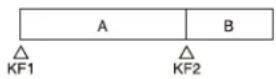
- With the following settings, black video or still image appears momentarily when playback switches from file A to file B:
| KF1 action Status | of file A KF2 action | |
| Start Playback Start | ||
| Start Playback Cueup | ||
| Variable Speed Playback atvariable speed | Cueup | |
| Cueup Cueup Cueup | ||
- Some actions may not operate with the following settings.
| KF1 action Status of file A KF2 action | ||
| Start Playback Variable Speed | ||
| Variable Speed Playback at variable speed | Variable Speed | |
| Cueup Cueup Variable Speed | ||
Does not operate when KF2 variable speed is set to a negative value. It does operate when the file B action is set to “Start” and then variable speed is set to a negative value after file B starts playing.
- With the following settings, switching from file A to file B does not occur.
| KF1 action Status | of file A KF2 action | |
| Variable Speed Playback at variable speed | Start | |
| Cueup Cueup Start | ||
If playback continues to show video of file A without switching to file B, a "Stop" action is required for file A in order to switch to file B.
- Loop/recue cannot be set on a timeline for the video disk communications protocol.
- When using the Odetics protocol, the variable speed action may not operate, depending on the connected device.
- Folder selection cannot be set on a timeline for the AMP protocol.
Setting an action
You can configure an action at a keyframe point on an effect timeline.
For details about setting an effect timeline, see “Effect Timeline Operations (Menu)” (page 272).
For a disk recorder, the target file must be loaded.
For details about loading a file, see “Disk Recorder File Operations” (page 234).
Notes
- Up to eight files can be configured for a single effect timeline.
- If you have not configured a file, the file loaded at the keyframe point when the effect timeline is executed becomes the target of the action.
- AMP protocol folder selection cannot be set on an effect timeline. The folder loaded at the keyframe point when an effect timeline is executed becomes the target of the action.
1 Open the Home > External Device > Device > Timeline > Action menu (16101.41).
DDR/VTR timeline settings information is displayed for each device channel number (1 to 12).
2 Select the target device for operation. 3 In the [Action] group, select an action to set.
Cueup: Set a cueup action.
Start: Set a start action.
Stop: Set a stop action.
Notes
- When both a stop point and variable speed are set for a start action, the variable speed setting takes priority.
- When a stop point timecode or the disk recorder end-of-file is reached before executing a stop action, operation stops at that point.
- When a start point is not set for a cueup action for a disk recorder, set cueup to the start of the file.
4 Press the left button in the [Start TC] group and enter a start point timecode in the numeric keypad window.
Note
If a start point is not configured for a disk recorder, the file loaded at the keyframe point when the effect timeline is executed becomes the target of the action.
To clear the setting
Press the [Clear] button in the [Start TC] group.
5 Press the left button in the [Stop TC] group and enter a stop point timecode in the numeric keypad window.
To clear the setting
Press the [Clear] button in the [Stop TC] group.
6 Press the left button in the [Variable Speed] group and enter a variable speed in the numeric keypad window.
To calculate variable speed automatically
Press the [Fit] button in the [Variable Speed] group. The duration calculated from the start point and stop point is compared with the keyframe duration, and the variable speed is calculated automatically.
To clear the setting
Press the [Clear] button in the [Variable Speed] group.
To test an action command output
Press the [Test Fire] button.
Setting an action when rewind is executed
On a DDR/VTR timeline, normally when the [REWIND] button is pressed, an action set for the first keyframe is not executed. When the [RUN] button is pressed, then the first keyframe action is executed.
To execute a specific action when the [REWIND] button is pressed, set a rewind action.
Note
The rewind action is enabled when you press the [REWIND] button, even if you have configured an action for the first keyframe to be executed after rewinding.
For details, see "Setting the operation of the first keyframe when rewind is executed" (page 447).
1 Open the Home > External Device > Device > Timeline > Rewind Action menu (16101.42). Rewind action settings information is displayed for each device channel number (1 to 12).
2 Select the target device for operation.
3 In the [Action] group, select an action to set.
Cueup: Set a cueup action.
Start: Set a start action.
Stop: Set a stop action.
4 Press the left button in the [Start TC] group and enter a start point timecode in the numeric keypad window.
To clear the setting
Press the [Clear] button in the [Start TC] group.
5 Press the left button in the [Stop TC] group and enter a stop point timecode in the numeric keypad window.
To clear the setting
Press the [Clear] button in the [Stop TC] group.
6 Press the left button in the [Variable Speed] group and enter a variable speed in the numeric keypad window.
To clear the setting
Press the [Clear] button in the [Variable Speed] group.
To set a currently loaded file as the rewind action target
Press the [File Set] button.
To test an action command output
Press the [Test Fire] button.
Disk Recorder File Operations
Recorded content on a disk recorder is managed as files.
Loading a File
To control playback and other operations on a disk recorder, the target file from the file list in the disk recorder must be loaded.
Note
Folder selection is required for the AMP protocol. The files in the selected folder are displayed in the file list.
For details, see "Selecting a folder" (page 235).
File list sharing
You can share the file list when a single disk recorder is connected to multiple ports.
For details, see "Configuring file list sharing" (page 440).
Note
A file list cannot be shared for the AMP protocol.
Updating a file list
1 Open the Home > External Device > Device > File List menu (16101.21). 2 Display the target device to set.
Select a tab to change the device (Device Ch1 to Device Ch12) to display.
3 Press the [Refresh] button.
The file list is updated. The file list shows the number, file name, file duration, and the update date and time of the files.
Notes
- The update date and time of the files are not displayed for the video disk communications protocol.
- The file duration and file update date and time are not displayed for the Odetics protocol.
- If sharing a file list, the file list must be updated on each target device (Device Ch1 to Device Ch12). For details about sharing a file list, see "Configuring file list sharing" (page 440).
To sort the file list display
You can press a display item title to sort the display. Pressing a title switches between ascending and descending order each time you press the title, and [▲] (ascending) or [▼] (descending) is displayed on the right side of the title. No.: Sort by number File Name: Sort by file name Updated Date/Time: Sort by modification date and time
Note
Sorting by update date and time is not supported for the video disk communications protocol and Odetics protocol.
Selecting a folder
Select a folder for the AMP protocol.
1 Open the Home > External Device > Device > Folder List menu (16101.11). 2 Display the target device to set. Select a tab to change the device (Device Ch1 to Device Ch12) to display. 3 Press the [Refresh] button. The folder list is updated. The folder list shows the number and folder name.
To sort the folder list display
You can press a display item title to sort the display. Pressing a title switches between ascending and descending order each time you press the title, and [▲] (ascending) or [▼] (descending) is displayed on the right side of the title. No.: Sort by number Folder Name: Sort by folder name
4 Select a folder.
You can also press the [Select Folder] button and enter a folder number in the numeric keypad window.
5 Press the [Set] button.
The selected folder is set as the target.
Loading a file
Select the target file to load.
Note
A file cannot be loaded if the type of disk recorder is set to [Recorder].
1 Open the Home > External Device > Device > File List menu (16101.21). 2 Display the target device to set. Select a tab to change the device (Device Ch1 to Device Ch12) to display. 3 Select a file. You can also press the [Select File] button and enter a file number in the numeric keypad window. 4 Press the [Load] button.
Creating a file
A new file must be created to record on a disk recorder (video disk communications protocol).
Note
A file cannot be created if the type of disk recorder is set to [Player].
1 Open the Home > External Device > Device > File List menu (16101.21). 2 Display the target device to set.
Select a tab to change the device (Device Ch1 to Device Ch12) to display.
3 Press the [New File] button.
The [New File] window appears.
4 Press the input field and enter a file name using the keyboard.
Enter 8 or up to 23 characters.
For details about the number of file name characters, see “Setting a Disk Recorder (VDCP)” (page 457).
5 Press [OK].
To unload the selected recording file
Press the [Unload] button.
Control of P-Bus Devices
You can control a P-Bus (Peripheral Bus II protocol) external device via a serial port or network port.
P-Bus control modes
The following two types of mode can be selected.
For details about setting the mode, see “Setting the P-Bus Control Mode” (page 440).
P-Bus trigger: Output an action command assigned to a specific button to operate an external device. P-Bus timeline: Set an action command at a keyframe point on an effect timeline to operate an external device.
P-Bus control actions
You can configure the following action commands.
- Store
- Recall
- Trigger
P-Bus Timeline
A P-Bus timeline is an effect timeline for a P-Bus device. You can configure an action at a keyframe point on an effect timeline to operate a P-Bus device.
At any single keyframe point, you can set actions for a maximum of 24 devices.
Executing a P-Bus timeline will output an action command for the target device when the keyframe point configured with that action is reached.
Note
This can be configured only when a P-Bus timeline is the P-Bus control mode.
For details about setting the mode, see “Setting the P-Bus Control Mode” (page 440).
Setting an action
You can configure an action at a keyframe point on an effect timeline.
For details about setting an effect timeline, see “Effect Timeline Operations (Menu)” (page 272).
1 Open the Home > External Device > P-Bus > Timeline > Action menu (16102.11).
P-Bus timeline settings information is displayed for each device (0 to 23).
2 Select the target device for operation.
To select and set multiple devices, place a check mark beside the target devices to set.
To select and set all devices, place a check mark in the 'select all' checkbox.
3 Press the [Action] button and select an action to set from the pull-down list.
Off: Do not set an action.
Store: Set a store action.
Recall: Set a recall action.
Trigger: Set a trigger action.
4 Press the [Action No.] button and enter a register number or trigger number in the numeric keypad window.
When a store action or recall action is selected, set a register number (1 to 4095).
When a trigger action is selected, set a trigger number (0 to 15).
To test an action command output
Press the [Test Fire] button.
Executing the P-Bus "Learn" command
You can execute the Learn command in a specified register number for a selected device.
1 Open the Home > External Device > P-Bus > Timeline > Action menu (16102.11).
P-Bus timeline settings information is displayed for each device (0 to 23).
2 Select the target device for operation.
3 Press the [Direct Store] button and enter a register number (1 to 4095) in the numeric keypad window.
Setting an action when rewind is executed
On a P-Bus timeline, normally when the [REWIND] button is pressed, an action set for the first keyframe is not executed. When the [RUN] button is pressed, then the first keyframe action is executed.
To execute a specific action when the [REWIND] button is pressed, set a rewind action.
Note
The rewind action is enabled when you press the [REWIND] button, even if you have configured an action for the first keyframe to be executed after rewinding.
For details, see “Setting the operation of the first keyframe when rewind is executed” (page 447).
1 Open the Home > External Device > P-Bus > Timeline > Rewind Action menu (16102.12).
Rewind action settings information is displayed for each device (0 to 23).
2 Select the target device for operation.
To select and set multiple devices, place a check mark beside the target devices to set.
To select and set all devices, place a check mark in the 'select all' checkbox.
3 In the [Action] group, select an action to set.
Off: Do not set an action.
Store: Set a store action.
Recall: Set a recall action.
Trigger: Set a trigger action.
4 Press the [Action No.] button and enter a register number or trigger number in the numeric keypad window.
When a store action or recall action is selected, set a register number (1 to 4095).
When a trigger action is selected, set a trigger number (0 to 15).
To test an action command output
Press the [Test Fire] button.
P-Bus Trigger
In a P-Bus trigger, you can output an action command to a P-Bus device using the control panel and menu buttons.
Note
This can be configured only when a P-Bus trigger is the P-Bus control mode.
For details about setting the mode, see “Setting the P-Bus Control Mode” (page 440).
The following gives the buttons that can be used and action commands that are output.
Utility/shotbox control block
[RUN] button: Trigger 1
[REWIND] button: Trigger 4
[NEXT KF] button: Trigger 7
[PREV KF] button: Trigger 8
Utility control block
[RUN] button: Trigger 1
[REWIND] button: Trigger 4
Numeric keypad control block
[RCALL] button: Recall
[STORE] button: Learn
[Effect Timeline Recall/Store] taskbar
[Run] button: Trigger 1
[Rewind] button: Trigger 4
[Effect Timeline Edit] taskbar
[Next KF] button: Trigger 7
[Previous KF] button: Trigger 8
[Recall/Store Register] window 1)
[Recall] button: Recall
Outputting an action command
This section describes output of the Recall command in the [Recall/Store Register] window as an example.
1 Press the [Recall/Store] button on the [Effect Timeline Recall/Store] taskbar or [Effect Timeline Edit] taskbar.
The [Recall/Store Register] window appears.
2 Select the P-Bus region.
On the [External Device] tab, set the [P-Bus] button to the on state.
3 Press the [Recall] button.
4 Enter a register number (1 to 999) in the numeric keypad area.
5 Press [Enter].
The Recall command is output.
Control of GPI Devices
You can control a GPI external device via a GPI output port.
Operate an external device using a GPI timeline.
GPI Timeline
A GPI timeline is an effect timeline for a GPI device. You can configure a GPI output port as an action at a keyframe point on an effect timeline to operate a GPI device.
Up to eight GPI output ports that output a trigger pulse can be configured for a single keyframe point.
Executing a GPI timeline outputs a trigger pulse to an external device from a GPI output port at the keyframe point for which an action is configured.
Setting an action
You can configure an action at a keyframe point on an effect timeline.
For details about setting an effect timeline, see “Effect Timeline Operations (Menu)” (page 272).
1 Open the Home > External Device > GPI > Timeline > Action menu (16103.11).
GPI timeline settings information is displayed for each GPI timeline port (1 to 8).
2 Select the target GPI timeline port (1 to 8) for operation.
3 Set the [GPI Action] switch to the on state.
To disable an action, set the [GPI Action] switch to the off state.
4 Press the [GPI Port] button and enter a GPI output port number in the numeric keypad window.
Note
Set the trigger type for a GPI output port set as a GPI timeline port to [Rising Edge], [Falling Edge], or [Any Edge].
For details, see "Setting a GPI Output" (page 454).
To disable all action settings
Press the [All Off] button.
To test a trigger output
Press the [Test Fire] button.
Setting an action when rewind is executed
On a GPI timeline, normally when the [REWIND] button is pressed, an action set for the first keyframe is not executed. When the [RUN] button is pressed, then the first keyframe action is executed.
To execute a specific action when the [REWIND] button is pressed, set a rewind action.
Note
The rewind action is enabled when you press the [REWIND] button, even if you have configured an action for the first keyframe to be executed after rewinding.
For details, see “Setting the operation of the first keyframe when rewind is executed” (page 447).
1 Open the Home > External Device > GPI > Timeline > Rewind Action menu (16103.12).
Rewind action settings information is displayed for each GPI timeline port (1 to 8).
2 Select the target GPI timeline port for operation.
3 Set the [GPI Action] switch to the on state.
To disable an action, set the [GPI Action] switch to the off state.
4 Press the [GPI Port] button and enter a GPI output port number in the numeric keypad window.
Note
Set the trigger type for a GPI output port set as a GPI timeline port to [Rising Edge], [Falling Edge], or [Any Edge].
For details, see "Setting a GPI Output" (page 454).
To disable all action settings
Press the [All Off] button.
To test a trigger output
Press the [Test Fire] button.
Control of Routers
Destination Input List Display
You can check destination inputs in the Home > External Device > Router > Router Xpt menu (16104.11).
The assigned destination and source are displayed for each destination selection delegation button (1 to 64).
Destinations that have Inhibit enabled are grayed out.
A lock icon is displayed for sources that have protection enabled on the MKS-R3210/R1620 Remote Control Panel.
Notes
- Delegation button numbers 65 to 128 are not displayed.
- The destination assignment and inhibit settings are configured in the Home > Setup > Panel > Router > Delegation Button Assign menu (19104.51). For details, see "Assigning a Destination" (page 441).
Selecting a Level
You can select the level used by the router.
For details about assigning the levels of level selection buttons, see “Setting Levels” (page 442).
1 Open the Home > External Device > Router > Router Xpt menu (16104.11). 2 In the [Level Button No./Level Assign] group, select a level selection button to use.
Select one of the [Level 1] to [Level 4] radio buttons.
Switching the Destination Input
You can switch the source for a destination.
For details about creating a source table, see “Assigning a Source Table” (page 441).
Note
Input switching is supported only for the destinations on delegation button numbers 1 to 64.
1 Open the Home > External Device > Router > Router Xpt menu (16104.11). 2 Select the target destination selection delegation button to set.
3 Press the [Select Source] button.
A source selection window appears.
4 Switch the source using the source selection buttons.
Select a tab to change the button number to display. Setting a source selection button to the on state switches the source.
Router Operations (AUX Bus Control Block)
Press the [RTR MODE] button on the cross-point pad in the AUX bus control block, turning it on, to switch to router operation mode.
You can select destinations and sources and perform other operations using the AUX bus control block in router operation mode.
For details about assigning destinations, sources, and levels, see “Setting a Router” (page 441).
Selecting a destination and source
Select a destination using the 1st row and 2nd delegation buttons in the AUX bus control block (router operation mode) and select a source using the 3rd row and 4th row cross-point buttons.
The delegation button rows/cross-point button rows may have different operation modes depending on whether second delegation mode is enabled/disabled.
The delegation button row/cross-point button row operations are the same as on the AUX bus control block (AUX bus operation mode).
For details, see “Operation Mode of a Button Row” (page 97) and “AUX bus control block” (page 100).
Note
The operation mode of the [SHIFT] button in delegation button rows/cross-point button rows in the AUX bus control block (router operation mode) is set in the Home > Setup > Panel > Router > Delegation Button Assign menu (19104.51) and Home > Setup > Panel > Router > Source Table Assign menu (19104.52).
For details about setting delegation button rows, see "Setting the operation mode of the shift button" (page 441).
For details about setting cross-point button rows, see "Setting the operation mode of the shift button" (page 442).
Selecting a level
Select using the [LEVEL BTN1] button to [LEVEL BTN4] button assigned to the cross-point pad.
Other Functions
Chapter
14
Utility Functions
The utility functions assign a specific function (action) to a button for recall when the button is pressed.
You can assign the following actions to the memory recall buttons in the utility/shotbox control block, the memory recall buttons in the utility control block, and the cross-point buttons in the cross-point control block.
- Utility command
- Recalling a macro register
- Recalling a shotbox register
- Recalling a panel memory register
- Menu shortcut
For details about assignment, see “Assigning a Utility Function” (page 431).
Note
To use the menu shortcut function, the control panel must be linked with the menu.
For details, see “Linking a Control Panel with the Menu” (page 87).
Status of buttons assigned with an action
When a button is set to the on state (when the action is executed), the status of the button changes as described below.
The status of a button assigned with a utility command depends on the command.
For details, see “Status of buttons assigned with a utility command” (page 243).
Memory recall buttons in the utility/shotbox control block and utility control block
When a macro register recall or shotbox register recall is assigned:
On: Lit orange
Off: Lit dark blue
For an empty register, gray characters are displayed on black.
When a menu shortcut is assigned:
On: Lit light purple
Off: Lit purple
Cross-point buttons in the cross-point control block
On: Lit amber
Off: Not lit
List of Utility Commands
The following utility commands can be assigned.
| Command Function | |
| M/E-x PGM1 ST a)M/E-x PGM2 ST a)M/E-x PGM3 ST a)M/E-x PGM4 ST a) | Enable/disable M/E-x program output safe titlex = 1 to 5 |
| M/E-x PVW ST a) | Enable/disable M/E-x preview output safe titlex = 1 to 5 |
| M/E-x CLEAN ST a) | Enable/disable M/E-x clean output safe titlex = 1 to 5 |
| M/E-x K-PVW1 ST a)M/E-x K-PVW2 ST a) | Enable/disable M/E-x key preview output safe titlex = 1 to 5 |
| P/P PGM1 ST a)P/P PGM2 ST a)P/P PGM3 ST a)P/P PGM4 ST a) | Enable/disable P/P program output safe title |
| P/P PVW ST a) | Enable/disable P/P preview output safe title |
| P/P CLEAN ST a) | Enable/disable P/P clean output safe title |
| P/P K-PVW1 ST a)P/P K-PVW2 ST a) | Enable/disable P/P key preview output safe title |
| Color Bkgd2 ST a) | Enable/disable color background 2 output safe title |
| DME Monitor Video ST a) | Enable/disable DME monitor video output safe title |
| DME Monitor Key ST a) | Enable/disable DME monitor key output safe title |
| Frame Memory1 to 16 ST a) | Enable/disable frame memory output (1 to 16) safe title |
| Clip Player1 to 4 ST a) | Enable/disable clip player output (1 to 4) safe title |
| Multi Viewer1 ST a)Multi Viewer2 ST a) | Enable/disable multi viewer output (1, 2) safe title |
| Edit Preview ST a) | Enable/disable edit preview output safe title |
| Preset ST a) | Enable/disable preset output safe title |
| Aux 1 to 48 ST a) | Enable/disable AUX output (1 to 48) safe title |
| GPI 1 to 50 Test Fire Output test trigger from GPI output port | |
| Macro Attachment Enbl Enable/disable macro attachment | |
| Macro AT with Rate | Register the transition rate when registering an auto transition macro event |
| Macro AT with A/B Bus | Register the background A bus/B bus cross-points when registering an auto transition macro event |
| Macro TL with Region | Register the target region when registering an effect timeline macro event |
| Pre Macro Set macro attachment in pre-macro mode | |
| Post Macro Set macro attachment i n post-macro mode | |
| Macro Take Resume macro execution(Enabled in step execution mode or during a pause event with a pause time of “0”) | |
| Macro All Take Resume all paused macros in multi mode(Enabled in multi mode during a pause event with a pause time of “0”) | |
| Macro Auto Ins Enable/disable macro auto insert mode | |
| Macro Cancel Stop macro execution | |
| Macro All Cancel Stop all simultaneous executing macros in multi mode | |
| DME Override Enable/disable DME override | |
| DME Graphic | Enable/disable DME graphics display(Applied to graphics for channel selected in device control block) |
| FTB | Enable/disable fade-to-black |
| AUTO PVW Auto preview | |
| Preset PVW Preset preview | |
| M/E-x Preview M/E-x preview | x = 1 to 5 |
| P/P Preview P/P preview | |
| M/E-x Sub Preview M/E-x preview | on the sub side in multi program 2 modex = 1 to 5 |
| P/P Sub Preview P/P preview on the sub side in multi program 2 mode | |
| M/E-x K-PVW1M/E-x K-PVW2 | M/E-x key preview 1/key preview 2x = 1 to 5 |
| P/P K-PVW1P/P K-PVW2 | P/P key preview 1/key preview 2 |
| M/E-x Key1 to 8 Previewb) c) d) | M/E-x key 1 to key 8, key previewx = 1 to 5 |
| P/P Key1 to 8 Previewb) c) d) | P/P key 1 to key 8, key preview |
a) Applies only to output signals assigned in the Home > Setup > System > Output > Output Assign menu (19101.41). b) Cannot be assigned to cross-point buttons in the cross-point control block.
c) Linked to the key preview 1 setting in the Home > Setup > Switcher > Config > K-PVW Config menu (19103.14).
d) The target key menu (last recalled menu) is displayed when a button assigned with a utility command is double-pressed.
Status of buttons assigned with a utility command
| Command Utility control | rol block Cross-point control block | |||
| On Off On Off | ||||
| GPI 1 to 50 Test Fire Macro CancelMacro All Cancel | Flashes light purple only at the moment the button is pressed | Lit purple Flashes amber | only at the moment the button is pressed | Not lit |
| Pre Macro Post Macro | Lit orange while the button is pressed | Lit dark blue Lit amber while the button is pressed | blue the button is pressed | Not lit |
| Macro Take Macro All Take | Lit purple during macro pause(Gray characters displayed on black when the button is disabled) | Lit light purple during macro execution | Lit amber during macro pause | Not lit during macro execution |
| FTB Lit light purple, then | lit red when execution ends | Lit purple Lit amber, then | lit red when execution ends | Not lit |
| Other commands | Lit orange | Lit dark blue | Lit amber | Not lit |
Executing a Utility Function (Utility/Shotbox Control Block)
You can perform utility function operations using the memory recall section in the utility/shotbox control block.
Press a memory recall button assigned with an action to execute the utility function.
Note
When using two utility/shotbox control blocks, the action assignments are common to both.
Selecting a bank
A group comprising the 24 buttons of the memory recall section are called a “bank.”
There are 20 banks (1 to 20), and you select the target button for operation by switching the bank.
Press a [BANK1] to [BANK20] button to switch the memory recall section to function recall mode for the selected bank.
Note
By default, bank 1 to 6 selection buttons are assigned. To use bank 7 to 20, the bank 7 to 20 selection buttons must be assigned to assignable buttons beforehand.
For details about assigning buttons, see "Assigning Control Panel Buttons" (page 428).
Executing a utility function
1 Select a bank.
For details about selecting a bank, see "Selecting a bank" (page 243).
2 Press the button assigned with the target action to operate.
Executing a Utility Function (Utility Control Block)
You can perform utility function operations using the utility control block in utility/shotbox operation mode.
Memory recall section in utility/shotbox operation mode
When the [UTIL/SBOX] button in the utility control block is pressed, the [UTIL/SBOX] button is lit amber and the memory recall section switches to utility/shotbox operation mode. Press a memory recall button assigned with an action to execute the utility function.
Selecting a bank
A group comprising the 15 buttons of the memory recall section are called a "bank."
There are 20 banks (1 to 20), and you select the target button for operation by switching the bank.
You can switch banks using the following buttons.
To select bank 1 to 11: Press a [BANK1] to [BANK11] button.
To select bank 1 to 20: Press the [BANK SEL] button and enter a bank number (1 to 20) using the numeric keypad in the memory recall section.
Note
You can also assign the bank selection buttons for bank 12 to 20 to assignable buttons.
For details about assigning buttons, see “Assigning Control Panel Buttons” (page 428).
Executing a utility function
1 Press the [UTIL/SBOX] button.
The [UTIL/SBOX] button is lit amber and the memory recall section switches to utility/shotbox operation mode.
2 Select a bank.
For details about selecting a bank, see “Selecting a bank” (page 244).
3 Press the button assigned with the target action to operate.
Executing a Utility Function (Cross-Point Control Block)
You can operate a utility function in the cross-point button rows in the cross-point control block. Press a cross-point button assigned with an action to execute the utility function.
Note
Action assignments are common to all switcher banks.
Selecting a bank
A group comprising the buttons (ICP-X7000: 36/28/20 buttons, ICP-X1000 series: 24/16 buttons) in a cross-point button row are called a “bank.”
There are 10 banks (1 to 10), and you select the target button for operation by assigning a bank to the cross-point button row.
You can assign a utility/shotbox bank using the following delegation buttons.
Notes
- You can assign the delegation buttons to use in key bus mode and free assign mode to the cross-point pad/ function button section. For details about assigning buttons in the cross-point pad, see “Setting a Cross-Point Pad” (page 436). For details about assigning buttons in the function button section, see “Assigning Control Panel Buttons” (page 428).
- In key/AUX bus delegation mode, you can assign delegation buttons to the 1st row. For details, see “Setting the key/AUX bus delegation mode button row” (page 434).
In key/AUX bus delegation mode
Press a [UTIL/SBOX1] to [UTIL/SBOX10] button in the 1st row, turning it on.
The utility functions for the selected bank are assigned to the 2nd row.
In key bus mode or free assign mode
Press one of the following buttons, turning it on.
- ICP-X7000: [UTL/SB1] button to [UTL/SB10] button assigned to the cross-point pad
- ICP-X1000 series: [UTIL/SBOX1] button to [UTIL/SBOX10] button assigned to the function button section
The utility functions for the selected bank are assigned to the 1st row or 2nd row in key bus mode, and to the 1st row to 4th row in free assign mode.
Executing a utility function
This section describes execution in key/AUX bus delegation mode as an example.
1. Select a bank using the delegation buttons in the 1st row.
For details about selecting a bank, see “Selecting a bank” (page 244).
The utility functions for the selected bank are assigned to the cross-point buttons in the 2nd row.
2. Press the button assigned with the target action to operate in the 2nd row.
Multi Program 2
Overview
This function divides the hardware of a single switcher bank into two (main and sub), allowing you to create images separately on each.
Note
Multi program 2 mode and M/E split cannot be set at the same time. Enabling M/E split will disable multi program 2 mode and switch to standard mode.
Main and sub
You can set separate backgrounds, keys, and transitions for main and sub in multi program 2 mode.
Program output on the main side
![graph TD A["Background A"] --> B["Eagles 3-2 Panthers"] B --> C["Key (key 1 to key 8)"] C --> D["Eagles Win!"]](/content/2026/06/1382172/images/d5197492af51d4154047c5950c38fa86f46e7c1f69cb62fd1277fffa6aefa109.jpg)
Program output on the sub side![graph TD A["Background B"] --> B["Eagles 3-2 Panthers"] C["Background A"] --> B D["Key (key 1 to key 8)"] --> E["Panthers Lose!"]](/content/2026/06/1382172/images/2b4ef299f33d05612ee8fb7d156944351f4ed2776a4c1ab6dae4edbd371f0e4e.jpg)
Main and sub assignments
There are two modes for operation: a mode switching a single M/E bank between main and sub, and a mode using main and sub assigned to two separate M/E banks. The illustration below shows ICP-X7000 cross-point control block.
Example:
M/E-1 main and sub shared on a single M/E bank

Example:
Dedicated M/E-1 main and dedicated M/E-1 sub on two M/E banks

Setting Multi Program 2 Mode
Setting multi program 2 mode flow
![graph TD A["Set the operation mode for a switcher bank (see page 411). <br>Set multi program 2 mode."] --> B["Set the outputs of each switcher bank (see page 411). <br>Set the Out1 to Out8 configuration."] B --> C["Assign a switcher bank (see page 426). <br>Set dedicated main and sub or share main a…](/content/2026/06/1382172/images/7039a1fba29e57baf51ed86fbc99d3651e813fe9dee393ecbd9a69bb0af170bb.jpg)
Setting control panel buttons when using dedicated main and dedicated sub
You can assign the assignable buttons in the cross-point control block, transition control block, transition control block (simple type), independent key transition control block, and Flexi Pad control block separately on main and sub.
For details about assigning buttons, see "Assigning Control Panel Buttons" (page 428) and "Setting a Cross-Point Pad" (page 436).
Setting control panel buttons when sharing main and sub
You can assign the main/sub switching buttons ([MAIN] button and [SUB] button) to the cross-point control block, transition control block, and transition control block (simple type).
For details about assigning buttons, see "Assigning Control Panel Buttons" (page 428) and "Setting a Cross-Point Pad" (page 436).
To switch operation to the main side, press the [MAIN] button, turning it on. To switch operation to the sub side, press the [SUB] button, turning it on. To operate main and sub simultaneously, press both the [MAIN] button and [SUB] button, turning them on.
Note
Switch between main and sub after a transition has completed.
Recalling a snapshot/effect timeline
You can also include the operation mode configuration data when recalling a snapshot or effect timeline.
For details about settings, see “Setting the recall target for an effect timeline/snapshot” (page 413).
Note
You can also automatically change the operation mode configuration data saved in a register when copy/move/swap operations are performed between main and sub registers.
For details about settings, see “Changing main/sub configuration data in multi program 2 mode” (page 286) and “Changing main/sub configuration data in multi program 2 mode” (page 298).
To change program output key assignments
When a snapshot or effect timeline is recalled on main or sub, only the keys being used on main and sub, according to the operation mode configuration data of the switcher bank, become the recall target.
When [Recall M/E Config] is enabled in the Home > Setup > Switcher > Config > M/E Config menu (19103.12), you can also change the key assignment in the Common > Key Priority/Key Assign menu of the switcher bank.
This section describes the M/E-1 menu as an example.
Note
The key assignment is linked to the Home > Setup > Switcher > Config > PGM Config menu (19103.13) settings.
1 Open the Home > M/E-1 > Common > Key Priority/Key Assign menu (11110.11).
The key assignment status of the program 1 output to program 4 output are shown at the bottom.
2 Select the target program output (PGM1 to PGM4) to set.
3 Press the [Edit] button.
The [Enable Key] window appears.
4 Place a check mark in the keys to enable.
Notes
- SL keys 5 to 8 are enabled/disabled as a group.
- SL keys are disabled for PGM2 to PGM4.
5 Press [OK].
Settings and functions added in multi program 2 mode
- Sub switcher bank menus (M/E-1 Sub to M/E-5 Sub, P/P Sub) are added.
- The sub switcher banks (M/E-1 Sub to M/E-5 Sub, P/P Sub) are added to the menu as setup targets.
- Sub switcher bank regions (M/E-1 Sub to M/E-5 Sub, P/P Sub) are added.
- Main and sub switcher banks and keys are shown on the transition control block display. Switcher banks: MAIN (dedicated main), SUB (dedicated sub), MAIN&SUB (shared main and sub) Keys: M (key assigned to main), S (key assigned to sub)
- The main and sub assignment status (MAIN, SUB, M&S) is displayed on the switcher bank name display buttons in the cross-point pad
- The [SUB TRANS] button in the key control block can be used.
- Utility 2 bus selection on the sub side is supported using the delegation buttons in the AUX bus control block.
- When extended re-entry is enabled for switcher banks, re-entry signals within the main switcher bank, within the sub switcher bank, and between main and sub switcher banks can be selected. For details about extended re-entry, see “Setting Extended Re-Entry” (page 413).
- “Sub” and “Main&Sub” settings are added to macro event parameters and macro attachment list buttons. For details about macro events, see “Macro Events” (page 564). For details about macro attachment lists, see “Macro Attachment Lists” (page 572).
- Sub switcher bank preview is added to the utility commands. For details about utility commands, see “List of Utility Commands” (page 242).
Image creation operation
This section describes the operation of a switcher bank shared between main and sub as an example.
To switch between main and sub, press the [MAIN] button or [SUB] button in the cross-point control block.
Note
You can also switch between main and sub using the [MAIN] button and [SUB] button in the transition control block and transition control block (simple type).
1. Press the [MAIN] button, turning it on. If the [SUB] button is lit, press the [SUB] button, turning it off. 2. Create the main side image. 3. Press the [MAIN] button, turning it off. 4. Press the [SUB] button, turning it on. 5. Create the sub side image. 6. Press the [MAIN] button, turning it on.
Both the [MAIN] button and [SUB] button should be turned on.
Note
When both the [MAIN] button and [SUB] button are selected, the control panel shows the status of the main side.
7. Execute a transition.
Both main side and sub side images are switched.
Multi Program 2 Mode Restrictions
In multi program 2 mode, settings and functions have the following restrictions.
- A key wipe has the following restrictions.
- Only standard wipe patterns can be used – Pattern mix cannot be used
- Split, pairing, modulation, spring, and spiral cannot be used
- Edge fill color matte is flat color only – Four types of multi replication are available for selection
- The key priority cannot be changed, depending on the transition. • Transition preview cannot be used.
- DMEs can be used in up to two locations simultaneously on main and sub.
- When using a DME wipe only
1-channel mode DME wipe: Can be used separately on main and sub.
2-channel mode or 3-channel mode DME wipe: Can be used on either main or sub only.
- When using a processed key only
One DME channel: Can be used on two keys (main and/or sub).
Two to four DME channels: Can be used on one key (main or sub).
- When using the image effect function
Can be used on two backgrounds (background A bus/B bus on main and/or sub).
- On a sub switcher bank, configuration data cannot be copied or swapped.
- On a sub switcher bank, the “AUTO PVW” utility command cannot be used.
- In the following cases, a transition using the fader lever may not be performed correctly.
- When flip-flop mode/bus fixed mode are set differently on main and sub
- For 2-stroke operations, such as a pattern limit or preset color mix
- On a sub switcher bank, split faders cannot be used.
- When a snapshot/effect timeline is recalled simultaneously on main and sub, the following data is reflected in the settings for main.
-Keys – Switcher bank operation mode – DME external video bus and utility 1 bus
- When a snapshot/effect timeline is recalled which has a different operation mode setting than the current switcher bank operation mode, the following occurs.
- If the operation mode is not a target of the snapshot/effect timeline, the current operation mode configuration is used.
- If the operation mode is a target of the snapshot/effect timeline, the operation mode configuration data saved in the snapshot/effect timeline is applied and then the other data is recalled.
- The settings of the [MACRO ATTACH ENABLE] button/[MCRO ATTCH ENBL] button in the cross-point control block are common to main and sub.
- The setting of the [SHOW KEY] button in the key control block is common to main and sub.
- On DME utility 1 bus and DME utility 2 bus cross-point buttons, it is not possible to set separate macro attachments on main and sub.
- Link settings are maintained even when the switcher bank operation mode is changed. Change the link settings, as required.
- Since key 1 to key 8 are shared between main and sub, if the main and sub fader lever positions are different and you move the fader lever, the image changes instantaneously to the state of the most recently moved fader lever.
- When a preset color mix is selected on main or sub, it is not possible to perform an independent key transition operation on main and sub.
AUX Bus Functions
Selecting an AUX Bus/Edit Preview Bus Signal
You can select and switch AUX bus and edit preview bus signals using the menu. From the list of cross-point button numbers, select the button number assigned with a signal.
Note
In a multiple-box switcher configuration, signals other than those sent to the cross-point box cannot be selected on the AUX bus.
For details about sending to the cross-point box, see "Setting Re-Entry Signals" (page 424).
1 Open the Home > Other Effects > Aux Bus > Aux Xpt menu (18102.11). 2 Select the target bus for operation. 3 Press the [Edit] button.
A signal selection window for the selected bus appears.
4 Select a video signal or key signal in [Select Source Type].
To select a video signal, set the [Video] radio button to the on state.
To select a key signal, set the [Key] radio button to the on state.
5 Switch the signal using the cross-point selection buttons.
Select a tab to change the button number to display. Setting a cross-point selection button to the on state switches the cross-point.
AUX Mix
In addition to a switcher bank transition, you can also perform a transition between two AUX buses.
Assigning AUX buses to outputs for an AUX mix
Assign two AUX buses used for an AUX mix to consecutive odd-numbered and even-numbered outputs.
Select an output in the Home > Setup > System > Output > Output Assign menu (19101.41) and assign two consecutive AUX buses as a group (Aux1/2 to Aux47/48).
For details, see "Assigning an Output Signal" (page 396).
Executing an AUX mix (cross-point control block)
This section describes an AUX mix using the AUX1 bus and AUX2 bus as an example.
This switches from the image currently output on the AUX1 bus to a new image using an AUX mix.
Notes
- The button used to execute an AUX mix must be assigned to the cross-point pad/function button section of the cross-point control block beforehand. For details about assigning buttons in the cross-point pad, see “Setting a Cross-Point Pad” (page 436). For details about assigning buttons in the function button section, see “Assigning Control Panel Buttons” (page 428).
- The AUX mix transition rate is configured using the menu. For details about settings, see “Executing an AUX mix (menu)” (page 250).
1 Press the [AUX MIX] button, turning it on.
Use the [AUX MIX] button for the cross-point button row assigned with the AUX1 bus.
2 Select an image for after the transition in the cross-point button row assigned with the AUX1 bus.
The image during the transition is output on the AUX1 bus.
The selected image is output on the AUX2 bus.
Executing an AUX mix (AUX bus control block)
This section describes an AUX mix using the AUX1 bus and AUX2 bus as an example.
This switches from the image currently output on the AUX1 bus to a new image using an AUX mix.
Notes
- The button used to execute an AUX mix must be assigned to the cross-point pad of the AUX bus control block beforehand.
For details about assigning buttons, see "Setting a Cross-Point Pad" (page 436).
- The AUX mix transition rate is configured using the menu. For details about settings, see "Executing an AUX mix (menu)" (page 250).
1 Press the [AUX MIX] button, turning it on.
When second delegation mode is enabled and the AUX1 bus is selected using the 1st row delegation buttons, use the [AUX MIX] button for the 3rd row. When the AUX1 bus is selected using the 2nd row delegation buttons, use the [AUX MIX] button (2nd Aux Mix) for the 4th row.
2 Select an image for after the transition in the cross-point button row assigned with the AUX1 bus.
The image during the transition is output on the AUX1 bus.
The selected image is output on the AUX2 bus.
Executing an AUX mix (menu)
This section describes an AUX mix using the AUX1 bus and AUX2 bus as an example.
This switches from the image currently output on the AUX1 bus to a new image using an AUX mix.
1 Open the Home > Other Effects > Aux Bus > Aux Xpt menu (18102.11).
2 Select the AUX1 bus.
3 Press the [Edit] button.
The AUX1 bus signal selection window appears.
4 In [Aux Mix], set the [On] radio button to the on state.
To disable an AUX mix, set the [Off] radio button to the on state.
To set the transition rate
Press the button on the right of the [On] radio button and enter a transition rate in the numeric keypad window.
To switch the video signal and key signal
To select a video signal, set the [Video] radio button for [Select Source Type] to the on state.
To select a key signal, set the [Key] radio button for [Select Source Type] to the on state.
5 Execute an AUX mix using the cross-point selection buttons.
Select a tab to change the button to display.
Set the cross-point selection button assigned with the image for after the transition to the on state to execute the AUX mix.
The image during the transition is output on the AUX1 bus. The selected image is output on the AUX2 bus.
AUX Bus Color Corrector
You can set the following color corrector functions for AUX bus outputs.
- Video process • Primary color correction
- RGB clip
To use a color corrector, an AUX bus must be assigned to an output that can be configured with a color corrector/HDR converter.
For details about outputs that can be configured with a color corrector/HDR converter, see “Selecting Outputs Configurable with a Color Corrector/HDR Converter” (page 397).
Note
When AUX mix is enabled, the color corrector is set for odd-numbered AUX buses.
Setting a color corrector
1 Open the Home > Other Effects > Aux Bus > Aux Bus CCR menu (18102.21).
The color corrector settings information is displayed for each AUX bus.
The color space (BT.709 or BT.2020) is displayed for each AUX bus assigned to an output that can be configured with a color corrector/HDR converter.
2 Select the target AUX bus to set. 3 Set the [CCR] button in the [CCR] group to the on state.
The color corrector is enabled.
Set the video process, primary color correction, and RGB clip functions, as required.
To disable a color corrector
Set the [CCR] button in the [CCR] group to the off state.
To return color corrector settings to the defaults
Press the [Unity] button in the [CCR] group, check the message, then press [OK].
All color corrector function settings are returned to the defaults.
Setting the video process function
1 Open the Home > Other Effects > Aux Bus > Aux Bus CCR menu (18102.21). 2 Select the target AUX bus to set. 3 Set the [Video Process] button in the [Video Process] group to the on state and set the following parameters.
| No. | Parameter Adjustment |
| 1 | Video Gain Video signal gain |
| 2 | Y Gain Luminance signal gain |
| 3 | C Gain Chrominance signal gain |
| 4 | Hue Delay Hue delay |
| 5 | Black Level Black level |
To return the video process function settings to the defaults
Press the [Unity] button in the [Video Process] group.
Setting primary color correction
The following types of correction can be applied to each of the RGB signals.
- Black balance adjustment: Sets the output level for a 0% level input signal.
- White balance adjustment: Sets the output level for a 100% level input signal.
- Gamma correction: Adjusts the curvature of the gamma curve.
- Knee correction: Adjusts the position of the knee of the gamma curve.
![graph TD A["Input level Black balance adjustment"] --> B["Output level White balance adjustment"] C["Input level Knee correction"] --> D["Output level Unadjusted signal"] E["Input level Gamma correction"] --> F["Output level Unadjusted signal"] style A fill:#f9f,stroke:#333 style C fill:#f9f,stroke:…](/content/2026/06/1382172/images/03e80142484ee478270fbf82f1cdff27cfa8a7419e67db4578d067e2cf192960.jpg)
1 Open the Home > Other Effects > Aux Bus > Aux Bus CCR menu (18102.21). 2 Select the target AUX bus to set. 3 Set the [Primary CCR] button in the [Primary CCR] group to the on state. 4 In the [Primary CCR Adjust] group, select an adjustment item.
Black: Black balance adjustment
White: White balance adjustment
Gamma: Gamma correction
Knee: Knee correction
5 Set the following parameters.
| No. | Parameter Adjustment |
| 1 | Red R signal adjustment |
| 2 | Green G signal adjustment |
| 3 | Blue B signal adjustment |
| 4 | All Simultaneous adjustment of all RGB signals a) |
a) [Red] parameter value is shown.
To return primary color correction settings to the defaults
Press the [Unity] button in the [Primary CCR] group.
Setting RGB clip
1 Open the Home > Other Effects > Aux Bus > Aux Bus CCR menu (18102.21). 2 Select the target AUX bus to set. 3 Set the [RGB Clip] button in the [RGB Clip] group to the on state. 4 In the [RGB Clip Adjust] group, select an adjustment item.
Dark: Dark clip adjustment White: White clip adjustment
5 Set the following parameters.
| No. | Parameter Adjustment |
| 1 | Red R signal adjustment |
| 2 | Green G signal adjustment |
| 3 | Blue B signal adjustment |
| 4 | All Simultaneous adjustment of all RGB signals a) |
a) [Red] parameter value is shown.
To return the RGB clip settings to the defaults Press the [Unity] button in the [RGB Clip] group.
Enabling a link group
When a link group is enabled, selecting a specific AUX bus and setting the color corrector will apply the settings of all the AUX buses in the same link group. You can temporarily disable a link group to set individual settings for AUX buses within the link group.
For details about setting a link group, see “Setting a Color Corrector Link Group” (page 470).
Note
The enable/disable setting is applied to all link groups.
1 Open the Home > Other Effects > Aux Bus > Aux Bus CCR menu (18102.21).
2 Set the [Link Enable] button in the [Aux Bus CCR Link] group to the on state.
To disable a link group, set the [Link Enable] button to the off state.
To apply the same settings to color correctors in a group
If the settings of AUX bus color correctors within a group are different, you can set the same settings by copying the settings of a specific AUX bus.
Select an AUX bus and press the [Copy in Link Group] button in the [Aux Bus CCR Link] group.
The color corrector of all AUX buses in the group are set to the same settings as the selected AUX bus.
Color Backgrounds
Overview
A color background is a function used to create a color background image using a color signal generated by a dedicated generator.
When the system signal format is 2160P, one color background (color background 1) can be used. When the system signal format is 1080P, 1080PsF, 1080i, or 720P, two color backgrounds (color background 1 and color background 2) can be used.
Assign color background 1 and color background 2 to cross-point buttons, and select color background signals.
Types of color backgrounds
You can set a single color (color 1 only) or a color mix (mix of color 1 and color 2) color background.
In a color mix, color 1 and color 2 are mixed using a dedicated pattern. You can also add modifiers to the pattern.
Setting a Color Background
This section describes the color background 1 menu as an example.
Setting a single color background
1 Open the Home > Other Effects > Color Bkgd > Color Bkgd1 menu (18101.11).
2 Set the [Flat Color] button in the [Matte] group to the on state and set the following parameters.
| No. | Parameter Adjustment |
| 1 | Luminance Luminance |
| 2 | Saturation Saturation |
| 3 | Hue |
Setting a color mix color background
1 Open the Home > Other Effects > Color Bkgd > Color Bkgd1 menu (18101.11).
2 Set the [Mix Color] button in the [Matte] group to the on state and set the following parameters.
| No. | Parameter Adjustment | |
| 1 Size | Pattern size | |
| No. | Parameter Adjustment | |
| 2 Soft | Softness of the pattern contour | |
| 5 Pattern | Pattern number | a) |
a) Linked to the pattern number selected using the [Mix Pattern Select] button.
3 Press the [Mix Pattern Select] button.
A pattern selection window appears.
4 Set the button for the target pattern to the on state.
Note
Dedicated patterns 1 to 24 are the same as standard wipe patterns 1 to 24.
5 Press [OK].
6 Press the [Color 1] button and set color 1 using the following parameters.
| No. | Parameter Adjustment |
| 1 | Luminance Luminance |
| 2 | Saturation Saturation |
| 3 | Hue |
Note
The [Color 1] button parameters are common to the [Flat Color] buttons in the [Matte] group.
7 Press the [Color 2] button and set color 2 using the following parameters.
| No. | Parameter Adjustment |
| 1 | Luminance Luminance |
| 2 | Saturation Saturation |
| 3 | Hue |
To swap color 1 and color 2 in a color mix
Set the [Color Invert] button to the on state.
To set the pattern position (Position)
Set the [Position] button to the on state and set the following parameters.
| No. | Parameter Adjustment |
| 1 | Position H Horizontal positionNegative values move left.Positive values move right. |
| 2 | Position V Vertical positionNegative values move down.Positive values move up. |
To replicate a pattern (Multi)
You can replicate a pattern horizontally, vertically, or both up to 63 times.
For details about pattern layouts, see “Replicating a wipe pattern (Multi)” (page 169).
Set the [Multi] button to the on state and set the following parameters.
| No. | Parameter Adjustment | |
| 1 H | Multi Number of repetitions of pattern horizontally | |
| 2 V | Multi Number of repetitions of pattern vertically | |
| 3 Invert | Type Pattern layout (1 to 4) |
To set the aspect ratio of a pattern (Aspect)
Set the [Aspect] button to the on state and set the following parameter.
| No. | Parameter Adjustment |
| 1 Aspect | Aspect ratioNegative values expand vertically.Positive values expand horizontally. |
To rotate a pattern (Rotation)
In the [Rotation] group, select a rotation type.
Angle: Incline a pattern at a fixed angle.
Speed: Rotate a pattern at a fixed speed.
When the [Angle] button is selected, set the following parameter.
| No. | Parameter Adjustment | |
| 1 Angle | Inclination angle of patternA value of -100.00 corresponds to a rotation of one turn counterclockwise.A value of +100.00 corresponds to a rotation of one turn clockwise.A value of 0.00 corresponds to no rotation. | |
When the [Speed] button is selected, set the following parameter.
| No. | Parameter Adjustment | |
| 1 Speed | Rotation speed of patternA value of -100.00 corresponds to 1 revolution/second counterclockwise rotation.A value of +100.00 corresponds to 1 revolution/second clockwise rotation.A value of 0.00 corresponds to no rotation (stationary). | |
To make a wipe pattern like a window blind (Pairing)
Set the [Pairing] button to the on state and set the following parameter.
| No. | Parameter Adjustment |
| 1 Width | Width |
To add modulation to a pattern (Modulation)
In the [Modulation] group, select a modulation type.
H: Modulate a pattern in the horizontal direction.
V: Modulate a pattern in the vertical direction.
The modulation is set to a sine wave.
Set the following parameters.
| No. | Parameter Adjustment |
| 1 | Amplitude Amplitude of modulation |
| 2 | Frequency Frequency of modulation |
| 3 | Speed Speed of ripplesNegative values create waves in the down, left, and counterclockwise directions.Positive values create waves in the up, right, and clockwise directions. |
Image Effect
Overview
Image effect is a function used to apply a DME effect to the signal selected on the background A bus or B bus for output.
Notes
- Setting the image effect function introduces a one-frame delay in the image.
- In flip-flop mode, interchanging the background A bus and B bus signals also interchanges their image effect settings at the same time.
DME restrictions
- To use the DME function, the MZS-X1610 3D DME License (option) is required for each target box.
- When the system signal format is 2160P, the DME function must be enabled for use. For details about setting GPU functions, see “Setting a GPU” (page 384).
- The number of DME channels that can be used will vary, depending on the system signal format and the DME enhanced function mode setting. For details, see "DME channels" (page 204).
- The image effect function cannot be set when a background DME wipe is set.
Number of DME channels that can be used simultaneously
DMEs can be used in up to two locations simultaneously on a single switcher bank (processed key or image effect). The number of DME channels that can be used on a key depends on the image effect use, as given below.
When not using the image effect function:
One DME channel on each of two keys, or one to four DME channels on a single key can be used.
When using the image effect function on background A or B:
Only one DME channel can be used on a single key.
When using the image effect function on both background A and B:
DMEs cannot be used on keys.
Notes
- In multi program 2 mode, DMEs can be used in up to two locations (main and sub).
- When M/E split is enabled, one DME channel can be used on each of the two sub blocks.
Recalling a snapshot/keyframe
Picture flashing may occur when executing a snapshot or keyframe that uses the image effect. To prevent picture flashing from occurring, a flash prevention bus must be configured.
For details about setting a flash prevention bus, see "Configuring a Flash Prevention Bus for when Recalling DME Effects" (page 422).
Setting the Image Effect Function
This section describes the M/E-1 menu as an example.
Assigning a DME channel to a background bus
Note
Only one DME channel can be used on each background bus.
1 Open the Home > M/E-1 > Bus/Transition > Bus > Image Effect menu (11109.12).
2 In the [Image Effect] group, select the target background bus to set.
Background A: Background A bus
Background B: Background B bus
3 In the [DME Select] group, select a DME channel (DME 1 to DME 4) to assign.
You can check the DME channel status using the button display.
On: DME channel assigned to the selected background bus
Off: DME channel not assigned
Lock icon: DME channel assigned to a different key/bus
To select a DME channel assigned to a different key or bus
Use the override function. You can release the DME channel assignment for another key/bus and then select the DME channel.
To enable the override function, set the [Override] button to the on state.
The DME channel is assigned to the selected background bus and the lock icon displayed on the DME channel button disappears.
Executing the Image Effect Function
The image effect function can be executed on the cross-point control block of the target switcher bank.
The DME effect to use for the image effect function must be configured for the DME channel beforehand.
This section describes the background A bus as an example.
Note
The button used to execute the image effect function must be assigned to the cross-point pad/function button section of the cross-point control block beforehand.
For details about assigning buttons in the cross-point pad, see “Setting a Cross-Point Pad” (page 436).
For details about assigning buttons in the function button section, see “Assigning Control Panel Buttons” (page 428).
1 Press the [IMAGE] button, turning it on.
Use the [IMAGE] button for the cross-point button row assigned with the background A bus.
2 Select a signal on the background A bus.
The signal set by the DME effect is output.
Video Process
Overview
Video process is a function that adjusts the luminance and hue of the input signal.
You can enable/disable the video process function and make adjustments for the following buses on each switcher bank.
• Key fill 1 bus to key fill 8 bus - Background A bus and background B bus • Utility 1 bus and utility 2 bus
Video Process Memory
This function saves the latest adjustment values of the video process function for each pair number of the signals selected on the bus. The enable/disable setting of the video process function is not saved.
When you change the adjustments, the values are automatically saved, and these last values are recalled when the pair number is selected.
By enabling video process memory, regardless of the video process setting of each bus, you can adjust the video process function for each input signal.
For details about video process memory, see “Enabling/Disabling Video Process Memory” (page 420).
Setting the Video Process Function
You can set the video process function for the background A bus, background B bus, utility 1 bus, and utility 2 bus. This section describes the M/E-1 menu as an example.
For details about the video process function for a key fill bus, see “Video Process” (page 146).
1 Open the Home > M/E-1 > Bus/Transition > Bus > Video Process menu (11109.11). 2 Set the [Video Process] button for the target bus to the on state.
For background A bus
Set the [Video Process] button in the [Background A] group to the on state.
For background B bus
Set the [Video Process] button in the [Background B] group to the on state.
For utility 1 bus
Set the [Video Process] button in the [Utility 1] group to the on state.
For utility 2 bus
Set the [Video Process] button in the [Utility 2] group to the on state.
3 Set the following parameters.
| No. | Parameter Adjustment |
| 1 | Video Gain Video signal gain |
| 2 | Y Gain Luminance signal gain |
| 3 | C Gain Chrominance signal gain |
| 4 | Hue Delay Hue delay |
| 5 | Black Level Black level |
To return the video process function settings to the defaults
Press the [Unity] button for the target bus to set.
Safe Title
You can enable/disable the safe title function. When enabled, the safe title area is displayed.
You can set the safe title area display method (Box1, Box2, Cross, Grid) in the Home > Setup > System > Output > Safe Title menu (19101.43).
For details about settings, see “Setting the Safe Title Area” (page 398).
Note
You can enable/disable the safe title function using a utility command.
For details about utility commands, see “Utility Functions” (page 241).
1 Open the Home > Utility > Safe Title menu (18201.11).
2 Select a tab to switch the target to set.
[Output] tab: Output safe title settings
[Dedicated Out] tab: Dedicated output safe title settings
For details about outputs and dedicated outputs, see "Setting the Output Signal" (page 396).
3 Select the target output to set.
To select and set multiple outputs, place a check mark beside the target outputs to set.
To select and set all outputs, place a check mark in the 'select all' checkbox.
4 Enable/disable the safe title function using the [Safe Title] switch.
On: Enable the safe title function.
Off: Disable the safe title function.
Copy and Swap
Overview
You can copy the settings of a switcher bank or key to another switcher bank or key.
You can also swap the settings between switcher banks or keys.
The following settings can be copied/swapped.
- Switcher banks Copy/swap settings between switcher banks
- Keys Copy/swap settings between keys
- Wipes Copy/swap wipe settings between switcher banks
- DME wipes Copy/swap DME wipe settings between switcher banks
- Independent key transition wipes Copy/swap independent key transition wipe settings between keys
- Independent key transition DME wipes Copy/swap independent key transition DME wipe settings between keys • DMEs Copy/swap DME settings between DME channels
Copy/swap menus
Switcher banks
Copy/swap switcher bank settings using the Home > Utility > Copy/Swap > M/E menu (18201.31).
Notes
- The following settings cannot be copied/swapped.
- Setup data
- Wipe snapshots – DME wipe snapshots
- Snapshots – Effect timelines
- Key snapshots
- Key memory
- When using DME channels on a switcher bank to be copied, the DME channel selection status may not be able to be copied depending on the number of DME channels that can be used.
Keys
Copy/swap key settings using the Home > Utility > Copy/Swap > Key menu (18201.32).
Notes
- The following settings cannot be copied/swapped.
- The following settings cannot be copied/swapped.
Key snapshots
- Key memory
- Key memory
- When using DME channels on a key to be copied/swapped, the DME channel selection status may not be able to be copied/swapped depending on the number of DME channels that can be used.
- When settings for a normal key are copied to an SL key, the settings for functions that cannot be used on SL keys are reset to the default values.
Copy/swap wipe and DME wipe settings using the Home > Utility > Copy/Swap > Wipe/DME Wipe menu (18201.33).
Copy/swap wipe and DME wipe settings using the Home > Utility > Copy/Swap > Wipe/DME Wipe menu (18201.33).
Select a tab to change the target wipe for operation.
[Wipe] tab: Wipes
[Key Wipe] tab: Independent key transition wipes
[DME Wipe] tab: DME wipes
[Key DME Wipe] tab: Independent key transition DME wipes
DMEs
Copy/swap DME settings using the Home > Utility > Copy/Swap > DME menu (18201.34).
Executing a Copy/Swap
This section describes copying a wipe as an example.
1 Open the Home > Utility > Copy/Swap > Wipe/DME Wipe menu (18201.33). 2 Select the [Wipe] tab. 3 In the list on the left, select a copy source wipe. 4 In the list on the right, select a copy destination wipe. 5 Press the [Copy] button.
To swap
Select the wipes to swap in the lists on the left and right, and press the [Swap] button.
To undo a copy or swap
To undo a copy or swap immediately after copying/swapping, press the [Undo] button.
Executing a copy using buttons
You can perform the following copy functions using button operations on the control panel.
| Copy target Using buttons | |
| Switcher banks [SNAPSHOT] button in the Flexi Pad control block |
| Copy target Using buttons | |
| Keys [KEY1] button to [KEY8] button in key operation mode in the Flexi Pad control block | |
| Wipes [WIPE] button in the Flexi Pad control block | |
| DME wipes | [DME WIPE] button in the Flexi Pad control block |
To copy using control panel buttons, press and hold the copy source button and press the copy destination button. Example:
Copying a wipe
Press and hold the [WIPE] button in the Flexi Pad control block of the copy source switcher bank, and press the [WIPE] button in the Flexi Pad control block of the copy destination switcher bank.
DME Override
When DME override is enabled and an effect timeline or snapshot is recalled, the DME channel that was used when saving can be forcibly selected.
Note
If effects that use the same DME channel are recalled simultaneously in two or more regions, the DME channel is selected in the following order of priority.
P/P > P/P Sub > M/E-1 > M/E-1 Sub > M/E-2 > M/E-2
Sub > M/E-3 > M/E-3 Sub > M/E-4 > M/E-4 Sub >
M/E-5 > M/E-5 Sub
1 Open the Home > Utility > DME Override menu (18201.41).
2 Enable/disable the function using the [DME Override] button in the [DME Override] group.
On: Enable DME override.
Off: Disable DME override.
To disable DME channel selection while on-air
Set the [On Air Protect] button in the [DME Override] group to the on state.
When DME override is enabled, the DME channel being used on the switcher bank which is currently on-air will not be forcibly selected.
DME Channel Status Display
Open the Home > Utility > Status > DME menu (18201.51).
You can check the DME channel status.
An “On Air” icon is displayed for DME channels which are on-air.
Channel: DME channels
Bank: Switcher bank using the DME channels
Key/Bus: Key or bus using the DME channels
Key 1 to Key 8: Key 1 to key 8
Bkgd A: Background A bus
Bkgd B: Background B bus
“- - -” is displayed when using a DME wipe in a normal transition.
Type: Function using the DME channels
Processed Key: Processed key
DME Wipe: DME wipe
Image Effect: Image effect function
Effect Timelines
Chapter
15
Overview
An effect timeline is a function for arranging multiple keyframes on the time axis (timeline) and interpolating between successive keyframes to create an effect in which there is a continuous change in the image. You can save an effect timeline in a register and then recall it as required.
You register the status of an image at a single point in time in a keyframe. When an effect timeline is executed, the same status is reproduced at the registered keyframes.
Effect timeline registers
You can create an effect timeline for the following regions.
Switcher bank regions:
M/E-1 to M/E-5, P/P, M/E-1 Sub to M/E-5 Sub, P/P Sub
User regions:
User 1 to User 8
DME regions:
DME 1 to DME 4 (including DME Global)
External device regions:
Device 1 to Device 12, P-Bus, GPI, Macro
There are 250 effect timeline registers in the Device 1 to
Device 12 and P-Bus regions, and 99 in the other regions.
Work register
A work register is a temporary register used when editing an effect timeline.
When an effect timeline register is recalled, the register contents are loaded into the work register and then editing is performed on the work register. When saving after finished editing, the work register contents are written to an effect timeline register.
Recalling and Saving an Effect Timeline
To execute an effect timeline, recall the target effect timeline register.
By default, the first keyframe is executed when an effect timeline is recalled. You can also configure a setting such that the first keyframe is not executed.
For details about first keyframe operation, see “Setting the operation of the first keyframe when a register is recalled” (page 447).
To edit an effect timeline, recall the target effect timeline register and insert/modify keyframes.
To create an effect timeline, recall an empty register. You create and register keyframes one at a time, and then set the time and path for their continuous operation.
After creating or editing an effect timeline, save it in an effect timeline register.
Auto save
When auto save is enabled and another effect timeline register is recalled while editing an effect timeline, the edited effect timeline register is saved automatically.
For details about setting auto save, see “Saving an effect timeline automatically” (page 447).
Editing an Effect Timeline
You can insert, delete, and modify keyframes on an effect timeline.
When editing, the effect timeline must be stopped at the target position for editing (edit point) on the time axis.
You can set the edit point at keyframe positions or between keyframes.
Pause
You can pause an effect timeline by setting a pause at a keyframe.
To resume, perform the execution operation.
Keyframe loop
You can loop between keyframes of a specified range for a specified number of times.
Attributes
You can add specific attributes for running an effect timeline when it is recalled.
The attributes are set for an effect timeline register.
Note
Attributes cannot be added for an effect timeline of an external device region.
Attribute types
You can add the following attributes.
Effect dissolve: The image changes smoothly from the state before the effect timeline is recalled to the state at the start of the effect timeline.
Temporary attributes
Apart from attributes set in an effect timeline register, you can add temporary attributes when an effect timeline is recalled. Temporary attributes are set when recalling an effect timeline.
Duration and Delay
Duration
The effect timeline execution time is determined by the keyframe duration and effect duration.
Keyframe duration:
Execution time from a keyframe to the next keyframe.
In constant duration mode, it is not possible to change the keyframe duration.
Effect duration:
Execution time from the first keyframe to the last keyframe of the effect timeline.
When you change the effect duration, the keyframe duration for each keyframe in the effect timeline is automatically recalculated.
The following two types of duration mode are available for an effect timeline.
Variable duration mode:
Inserting or deleting a keyframe changes the effect duration accordingly.
Constant duration mode:
Inserting or deleting a keyframe does not change the effect duration. This is useful for keyframe editing with a fixed effect duration.
In variable duration mode and constant duration mode, the target keyframes for editing are different.
| Edit point Variable | duration mode | Constant duration mode |
| Edit target when an edit point is at a keyframe | Currently selected keyframe becomes the edit target. | Currently selected keyframe becomes the edit target. |
| Edit target when an edit point is between keyframes | Keyframe preceding the edit point becomes the edit target. | Editing a keyframe is not possible. |
The operation and effect duration when a keyframe is inserted/deleted depends on the duration mode as follows.
| Inserting a keyframe | Variable duration mode | Constant duration mode |
| When an edit point is at a keyframe | Effect duration increases by the size of the inserted keyframe. | Effect duration does not change.A new keyframe is inserted with the current keyframe duration, and the current keyframe duration is reset to 0. |
| When an edit point is between keyframes | Effect duration does not change. | Effect duration does not change. |
| Deleting a keyframe | Variable duration mode | Constant duration mode |
| When an edit point is at a keyframe | Effect duration decreases by the size of the deleted keyframe. | Effect duration does not change. The keyframe duration before the deleted keyframe is increased by the size of the deleted keyframe. |
| When an edit point is between keyframes | Previouskeyframe is deleted and the effect duration decreases by the size of the deleted keyframe. | Deleting a keyframe is not possible. |
Delay
You can set the delay time (effect timeline start point) between when an effect timeline execution is initiated and when the effect timeline actually begins.
Changing the delay does not alter the effect duration.
Keyframe Path
The keyframe path sets how an image changes from one keyframe to the next keyframe.
Setting the keyframe path sets how interpolation is performed between keyframes.
Note
The keyframe path cannot be set for an effect timeline of an external device region.
Executing an Effect Timeline
You can execute an effect timeline using the [RUN] button in the utility/shotbox control block and utility control block, or the [Run] button in the menu. You can set a loop for repeated execution.
You can specify the following execution directions of an effect timeline.
Normal: Executes from the first keyframe to the last keyframe.
Reverse: Executes from the last keyframe to the first keyframe.
Normal/Reverse: Execution direction changes each time the effect timeline execution finishes.
Note
Looping cannot be set for an effect timeline of an external device region. Only normal execution direction is supported.
Keyframe fader
You can execute an effect timeline manually using the fader lever in the transition control block/transition control block (simple type) on the ICP-X7000.
Effect Timeline List
Displaying the Effect Timeline List
Open the Home > Register > Effect Timeline > Timeline View > List menu (18301.11).
You can check the information in the effect timeline for each region in the timeline list.
A blue frame is displayed for the reference region.

① Effect timeline list display start point timecode
② Zoom out button
Shrinks the display of the effect timeline list.
③ Zoom in button
Enlarges the display of the effect timeline list.
④ Effect timeline list display stop point timecode
⑤ Region name
⑥ Register number and register name
⑦ Execution direction
Displays the effect timeline execution direction (normal direction or reverse direction) using an arrow icon.
⑧ Start point timecode
Displays the delay time between when an effect timeline execution is initiated and when the effect timeline actually begins.
⑨ Keyframe loop
Displays the number of loops remaining/number of loops specified and a loop icon when keyframe loop is set. The loop range is indicated by a blue bar.
⑩ Pause
Displayed when a pause is set.
⑪ Stop point timecode
⑫ Effect duration
⑬ Current keyframe number/number of keyframes
⑭ Current timecode
⑮ Cursor
Displays the position of the current timecode.
⑯ Keyframes
Displays the positions where a keyframe has been inserted.
When there are multiple keyframes, the number of keyframes set at the same position is displayed.
Setting the Effect Timeline List View
Setting the display order of regions
The timeline list displays both the regions selected as the operation target and then the regions that are not selected in their set order of priority.
1. Open the Home > Register > Effect Timeline > Timeline View > Assign menu (18301.12).
The order of priority is shown in the list on the left, and the regions that can be selected are shown in the list on the right.
2 In the list on the left, select the order of priority position.
3 In the list on the right, select a region for insertion.
4 Press the [Assign] button.
The selected region is inserted and the order of priority of subsequent regions are shifted down by one.
If a region configured in the list is the same as the selected region, the order of priority is updated.
To display in the configured order of priority regardless of the target selection
Set the [Auto-Assign Active Rgn] button to the off state.
Setting the display of regions on or off
You can select the regions shown in the timeline list.
1 Open the Home > Register > Effect Timeline > Timeline View > Assign menu (18301.12).
“Enabled” is displayed for [Display] in the list on the left for regions set for display.
2 In the list on the left, select the target region to set.
3 Set whether to display/hide the region using the [Display] button.
On: Display the region in the timeline list.
Off: Do not display the region in the timeline list.
Returning the region view to the initial settings
1 Open the Home > Register > Effect Timeline > Timeline View > Assign menu (18301.12).
2 Press the [Default Recall] button.
Effect Timeline Operations (Utility/Shotbox Control Block and Numeric Keypad Control Block)
You can edit an effect timeline in the utility/shotbox control block by recalling an effect timeline register in the numeric keypad control block.
You can perform operations on an effect timeline in a region assigned to a region selection button in the numeric keypad control block.
For details about regions, see “Types of Regions” (page 89).
Note
You can select a region that is not assigned to a region selection button in the [Recall/Store Register] window in the menu.
For details, see “Effect Timeline Operations (Menu)” (page 272).
Effect timeline operation mode (numeric keypad control block)
Press the [EFF] button in the numeric keypad control block, turning the [EFF] button and [RCALL] button on amber, to switch to effect timeline operation mode.
Select a region using the region selection buttons, then enter a register number in the numeric keypad area to select a register.
Note
Displaying the [Recall/Store Register] window or [Edit Timeline] window for an effect timeline using the menu switches the numeric keypad control block to effect timeline operation mode.
Selecting a region
You can select the target region to set using the region selection buttons.
Up to four regions (1 to 4) can be assigned to each region selection button. The name of the region assigned to the lowest region number is displayed on the button. Press a button, turning it on, to simultaneously select the assigned regions.
The first selected region using the region selection buttons becomes the reference region and the button is lit green. The buttons for subsequent selected regions are lit amber.
Press and hold a mode selection button ([EFF] button for an effect timeline, [SNAPSHOT] button for a snapshot) and press a region selection button that is lit amber, changing the button color to green, to change the reference region.
When the selected reference region is removed, the reference region will be set according to the order of priority.
The selected regions are shown on the display. The reference region is displayed highlighted. The name of the reference region is displayed at the bottom of the display on the right side.
For details about assigning region selection buttons, see “Assigning regions to a region selection button in the numeric keypad control block” (page 429).
For details about the order of priority for the reference region, see “Reference regions” (page 89).
You can press the [ALL] button to select all regions configured beforehand at the same time.
If you press the [ALL] button while none of the configured target regions are selected, then the target regions are selected at the same time and all other regions are deselected.
If you press the [ALL] button while at least one of the configured target regions is selected, all regions are deselected.
When regions are selected using the [ALL] button, the region with the highest priority becomes the reference region.
For details about setting the regions selected simultaneously, see “Setting Regions Selected Simultaneously” (page 428).
Note
When multiple regions are assigned to the region selection button that is lit green, the region with the highest priority becomes the reference region and an asterisk “*” is appended to the name of the reference region displayed at the bottom of the display on the right side.
To set another region assigned to the same button as the reference region, select the region in the [Select Region] window in the menu.
For details about [Select Region] window operations for an effect timeline, see "To select a region" (page 284).
For details about [Select Region] window operations for a snapshot, see “To select a region” (page 295).
Selecting a register
Select a register in the numeric keypad area.
Enter a register number in the numeric keypad area and press the [ENTER] button to apply the setting.
When you enter a register number, the register number and the following information appears at the bottom of the display on the right side.
e: The register is empty for the currently selected region.
E: The register is empty for all selectable regions.
L: The register is locked.
To search for an empty register, press [.] (period).
To search for an empty register common to all selectable regions, press [.] (period) again.
Notes
- For shotboxes and macros, the register number plus "E" (register is empty) or "L" (register is locked) is displayed. To search for an empty register, press [.] (period) once.
- While a mode selection button ([EFF] button for an effect timeline, [SNAPSHOT] button for a snapshot, [MCRO] button for a macro) is pressed, the register name is displayed at the bottom of the display on the right side.
Effect Timeline/Macro Edit Mode (Utility/Shotbox Control Block)

Pressing the [KF MCRO EDIT] button in the utility/shotbox control block, turning the [KF MCRO EDIT] button on amber, switches the memory recall section to effect timeline/macro edit mode.
You can create and edit an effect timeline by pressing the [EDIT ENBL] button, turning it on orange, to enable effect timeline edit mode.
Note
Creating/editing an effect timeline is supported only when an effect timeline register is recalled in effect timeline operation mode in the numeric keypad control block.
Recalling an Effect Timeline
You can recall an effect timeline register by switching the numeric keypad control block to effect timeline operation mode.
Notes
- The first keyframe is executed when an effect timeline is recalled. You can also configure a setting such that the first keyframe is not executed. For details about settings, see “Setting the operation of the first keyframe when a register is recalled” (page 447).
- You can configure a setting such that the state at that point in time is inserted automatically as the first keyframe when an empty effect timeline register is recalled.
For details about settings, see "Inserting the first keyframe automatically when an empty register is recalled" (page 446).
- You can configure a setting such that when another effect timeline register is recalled while editing an effect timeline, the edited effect timeline is saved automatically (auto save function).
For details about settings, see “Saving an effect timeline automatically” (page 447).
- You can configure a setting such that effect timeline edit mode ends when a register is recalled when the utility/shotbox control block is in effect timeline edit mode.
For details about settings, see “Exiting edit mode automatically when a register is recalled during editing” (page 447).
1 Press the [EFF] button.
The [EFF] button and [RCALL] button turn on amber, and the numeric keypad control block switches to effect timeline operation mode.
2 Select the target region to set using the region selection buttons.
You can select multiple regions.
For details about selecting a region, see “Selecting a region” (page 265).
To select all regions configured beforehand, press the [ALL] button.
For details about setting the regions selected simultaneously, see “Setting Regions Selected Simultaneously” (page 428).
3 Enter a register number in the numeric keypad area.
For details about selecting a register, see “Selecting a register” (page 266).
To add a temporary attribute
Press the [EFF DISS] button, turning it on green.
4 Press the [ENTER] button.
The specified register is recalled.
To undo a register recall
To undo a recall immediately after recalling a register, press the [UNDO] button.
Saving an Effect Timeline
An effect timeline register can be saved by switching the numeric keypad control block to effect timeline operation mode.
1 Press the [EFF] button.
The [EFF] button and [RCALL] button turn on amber, and the numeric keypad control block switches to effect timeline operation mode.
2 Select the target region to set using the region selection buttons.
You can select multiple regions.
For details about selecting a region, see “Selecting a region” (page 265).
To select all regions configured beforehand, press the [ALL] button.
For details about setting the regions selected simultaneously, see “Setting Regions Selected Simultaneously” (page 428).
3 Press the [STORE] button, turning it on amber.
4 Enter a register number in the numeric keypad area.
The currently recalled register number is displayed on the display on the right side. To select another register, enter a register number.
For details about selecting a register, see “Selecting a register” (page 266).
5 Press the [ENTER] button.
The effect timeline is saved in the specified register. The [RCALL] button and [STORE STATS] button turn on amber.
To undo saving of an effect timeline
While the [STORE STATS] button is lit amber, press and hold the [STORE STATS] button and press the [UNDO] button.
Creating and Editing an Effect Timeline
You can create and edit an effect timeline by recalling an effect timeline register.
After creating and editing an effect timeline, save it in an effect timeline register.
Effect timeline creation/edit flow
![graph TD A["Numeric keypad control block: Select a region (see page 266). Select the target region to set."] --> B["Numeric keypad control block: Recall an effect timeline register (see page 266). When creating, recall an empty register. When editing, recall the target register to edit."] B --> C["U…](/content/2026/06/1382172/images/dfd69f64bd49ca5debec61ea4d71914105cd40a7930ca3a9e0698a2adbaae2e4.jpg)
Note
The path setting is configured in the menu.
After a keyframe path is changed, the [MOD] button in the utility/shotbox control block must be pressed to apply the modifications.
Editing a keyframe
You can edit an effect timeline by switching the utility/shotbox control block to effect timeline/macro edit mode.
Note
The operations during editing and the duration after editing may vary depending on the effect timeline duration mode.
For details, see "Duration and Delay" (page 262).
1 Press the [KF MCRO EDIT] button.
The memory recall section switches to effect timeline/macro edit mode.
2 Press the [EDIT ENBL] button, turning it on orange.
Effect timeline edit mode becomes enabled.
3 Edit using the edit buttons.
Selecting an edit point
Move to the target position for editing (edit point) on the effect timeline.
To move to the previous keyframe
Press the [PREV KF] button.
To move to the next keyframe
Press the [NEXT KF] button.
To move to a specified timecode
Press the [GOTO TC] button, enter a timecode in the numeric keypad area of the numeric keypad control block, and press the [ENTER] button.
Notes
- You can also enter a difference value from the currently set value using the [TRIM] button. For details, see “Entering a difference from a current value” (page 88).
- If multiple keyframes are positioned at the same timecode, the keyframe with the lowest number is selected.
To move to a specified keyframe number
Press the [GOTO KF] button, enter a keyframe number in the numeric keypad area of the numeric keypad control block, and press the [ENTER] button.
Note
You can also enter a difference value from the currently set value using the [TRIM] button.
For details, see “Entering a difference from a current value” (page 88).
Inserting a keyframe
1 Select an edit point. 2 Create the keyframe to insert. 3 Press the [INS] button. The keyframe is inserted after the selected position.
To insert before the selected position, press and hold the [SHIFT] button and press the [INS] button.
Modifying a keyframe
1 Select an edit point (keyframe). 2 Modify a keyframe. 3 Press the [MOD] button. The keyframe is modified.
Note
You can also select and modify multiple keyframes. For details, see “Selecting multiple keyframes” (page 269).
To modify multiple keyframes using relative values
Press and hold the [SHIFT] button and press the [MOD] button.
For details about modifying using relative values, see "Differences in modification between [Modify] button (absolute values) and [Relative Modify] button (relative values)" (page 275).
Deleting a keyframe
1 Select an edit point (keyframe). 2 Press the [DEL] button. The keyframe at the selected position is deleted.
Note
You can also select and delete multiple keyframes. For details, see "Selecting multiple keyframes" (page 269).
To move a keyframe
Delete a keyframe, select an edit point, and press the [PASTE] button. The deleted keyframe is inserted after the selected position. To insert before the selected position, press and hold the [SHIFT] button and press the [PASTE] button.
Copying a keyframe
1 Select a copy source edit point (keyframe). 2 Press the [COPY] button.
3 Select a copy destination edit point.
4 Press the [PASTE] button.
The copied keyframe is inserted after the selected position. To insert before the selected position, press and hold the [SHIFT] button and press the [PASTE] button.
Note
You can also select and copy multiple keyframes. For details, see "Selecting multiple keyframes" (page 269).
Selecting multiple keyframes
You can select multiple keyframes as the edit target. This operation is available when modifying, deleting, or copying a keyframe.
To select all keyframes
Press the [ALL] button, turning it on orange.
To select multiple keyframes within a specified range
1 Select the first edit point (keyframe) for a specified range. 2 Press the [FROM TO] button. “FROM XXX TO” (“XXX” is the current keyframe number) is displayed on the display in the numeric keypad control block. 3 Enter the number of the last keyframe for the specified range in the numeric keypad area in the numeric keypad control block.
To change the number of the first keyframe in the specified range, press the [CLR] button. Enter the number of the first keyframe, press the [ENTER] button, and then enter the number of the last keyframe.
Note
If the last keyframe is not specified, the range up to the last keyframe on the effect timeline becomes the specified range.
4 Press the [ENTER] button.
The specified range is applied.
Setting pause at a keyframe
1 Select an edit point (keyframe).
2 Press the [PAUSE] button, turning it on orange.
A pause is set at the selected keyframe.
Setting keyframe loop
You can specify a range on an effect timeline to execute the range repeatedly.
A loop can be configured at only one location on an effect timeline.
1 Select the first edit point (keyframe) for a loop range.
2 Press the [KF LOOP] button, turning it on orange.
“FROM XXX TO” (“XXX” is the current keyframe number) is displayed on the display in the numeric keypad control block.
Note
During loop configuration operations in the numeric keypad control block, the [KF LOOP] button is lit blue.
3 Enter the number of the last keyframe for the loop range in the numeric keypad area in the numeric keypad control block.
To change the number of the first keyframe in the loop range, press the [CLR] button. Enter the number of the first keyframe, press the [ENTER] button, and then enter the number of the last keyframe. When the number of the last keyframe is entered and you press the [ENTER] button, “COUNT” is displayed on the display in the numeric keypad control block.
4 Enter the number of loop repetitions (1 to 99, or 0) in the numeric keypad area in the numeric keypad control block.
If “0” is entered, an infinite loop is specified.
5 Press the [ENTER] button.
The loop range and number of repetitions are applied.
Notes
- The loop between the specified first keyframe and last keyframe is maintained even if a keyframe is inserted/deleted within the loop range.
- If the first keyframe or last keyframe of the loop range is deleted, the loop is cleared.
Undoing an edit operation
To undo an operation immediately after inserting, modifying, deleting, or pasting a keyframe, press the [UNDO] button.
Setting the Duration and Delay
You can set the effect duration, keyframe duration, and delay to adjust the execution time of an effect timeline.
For details, see "Duration and Delay" (page 262).
Select the target region to set and an effect timeline register, and set the duration mode, duration, and delay. After configuration, save the effect timeline.
For details about recalling an effect timeline register, see "Recalling an Effect Timeline" (page 266).
For details about saving an effect timeline, see "Saving an Effect Timeline" (page 267).
You can configure duration and delay by switching the utility/shotbox control block to effect timeline/macro edit mode.
Setting the duration mode
1 Press the [KF MCRO EDIT] button. The memory recall section switches to effect timeline/macro edit mode. 2 Press the [EDIT ENBL] button, turning it on orange. 3 Set the duration mode using the [CONST DUR] button. Lit orange: Set to constant duration mode. Lit dark blue: Set to variable duration mode.
Setting the effect duration
1 Press the [KF MCRO EDIT] button. The memory recall section switches to effect timeline/macro edit mode. 2 Press the [EDIT ENBL] button, turning it on orange. 3 Press the [EFF DUR] button.
"DUR XXX:XX:XX" ("XXX:XX:XX" is the current effect duration) is displayed on the display in the numeric keypad control block.
4 Enter an effect duration in the numeric keypad area in the numeric keypad control block.
Enter a duration as a timecode (minute:second:frame).
Note
You can also enter a difference value from the currently set value using the [TRIM] button.
For details, see “Entering a difference from a current value” (page 88).
5 Press the [ENTER] button.
The effect duration is applied.
Setting the keyframe duration
Notes
- In constant duration mode, it is not possible to set the keyframe duration.
- You can set a default value for the keyframe duration. For details about settings, see “Setting the default keyframe duration” (page 447).
1 Press the [KF MCRO EDIT] button.
The memory recall section switches to effect timeline/macro edit mode.
2 Press the [EDIT ENBL] button, turning it on orange. 3 Select an edit point (keyframe).
The time from the selected keyframe to the following keyframe is the target to set.
4 Press the [KF DUR] button.
“KF DUR XXX:XX” (“XXX:XX” is the current keyframe duration) is displayed on the display in the numeric keypad control block.
5 Enter a keyframe duration in the numeric keypad area in the numeric keypad control block.
Enter a duration as a timecode (second:frame).
Note
You can also enter a difference value from the currently set value using the [TRIM] button.
For details, see “Entering a difference from a current value” (page 88).
6 Press the [ENTER] button.
The keyframe duration is applied.
Setting the delay
1 Press the [KF MCRO EDIT] button.
The memory recall section switches to effect timeline/macro edit mode.
2 Press the [EDIT ENBL] button, turning it on orange. 3 Press the [DELAY] button.
“DELAY XXX:XX” (“XXX:XX” is the current delay) is displayed on the display in the numeric keypad control block.
4 Enter a delay in the numeric keypad area in the numeric keypad control block.
Enter a delay as a timecode (second:frame).
Note
You can also enter a difference value from the currently set value using the [TRIM] button.
For details, see “Entering a difference from a current value” (page 88).
5 Press the [ENTER] button.
The delay is applied.
Effect Timeline Operations (Menu)
Recalling an Effect Timeline
Notes
- The first keyframe is executed when an effect timeline is recalled. You can also configure a setting such that the first keyframe is not executed. For details about settings, see “Setting the operation of the first keyframe when a register is recalled” (page 447).
- You can configure a setting such that the state at that point in time is inserted automatically as the first keyframe when an empty effect timeline register is recalled. For details about settings, see “Inserting the first keyframe automatically when an empty register is recalled” (page 446).
- You can configure a setting such that when another effect timeline register is recalled while editing an effect timeline, the edited effect timeline is saved automatically (auto save function). For details about settings, see “Saving an effect timeline automatically” (page 447).
- You can configure a setting such that effect timeline edit mode ends and operation switches to effect timeline recall/store mode when a register is recalled in edit mode. For details about settings, see “Exiting edit mode automatically when a register is recalled during editing” (page 447).
1 Display the [Effect Timeline Recall/Store] taskbar.
The effect timeline switches to recall/store mode.
2 Press the [Recall/Store] button.
The [Recall/Store Register] window appears.
Note
In the [Effect Timeline Edit] taskbar, press the [Recall/Store] button to display the [Recall/Store Register] window.
3 Set the button for the target region to the on state.
You can select multiple regions.
For details about the display in the region display section, see “Region display section” (page 273).
Select a tab to change the region to display.
[ME] tab: Switcher bank regions
[User] tab: User regions
[DME] tab: DME regions
[External Device] tab: External device regions. The first selected region becomes the reference region.
To select all regions configured beforehand, set the [All Regions] button to the on state.
For details about setting the regions selected simultaneously, see “Setting Regions Selected Simultaneously” (page 428).
To select DME local or DME global for the target region to edit
To select DME local, set the [DME Local] button to the on state.
To select DME global, set the [DME Global] button to the on state.
Notes
- The region selection is common for effect timelines and snapshots.
- DME local/DME global selection is enabled only when editing an effect timeline. When recalling, saving, or executing an effect timeline, both DME local and DME global become the target.
- The DME local/DME global selections are common for all DME regions.
- The DME local/DME global selections are linked to the [LOCAL] button/[GLB] button in the device control block.
4 Press the [Recall] button.
5 Enter a register number in the numeric keypad area.
For details about selecting a register, see “Selecting a register” (page 273).
To add a temporary attribute
Set [Effect Diss] in the numeric keypad area to the on state.
6 Press [Enter].
The specified register is recalled.
To undo a register recall
To undo a recall immediately after recalling a register, press the [Undo] button.
To set the duration for an effect dissolve temporary attribute
You can set the duration for an effect dissolve temporary attribute for each region.
Select the target region to set, press the [Temp Diss Duration] button, and enter a duration (number of frames) for the effect dissolve in the numeric keypad area.
Selecting a register
Select a register using the numeric keypad area at the bottom right of the [Recall/Store Register] window. Enter a register number in the numeric keypad area and press [Enter] to apply the setting.
When you enter a register number, the register number and the following information appears on the numeric keypad area display.
e: The register is empty for the currently selected region.
E: The register is empty for all selectable regions.
L: The register is locked.
To search for an empty register, press [.] (period).
To search for an empty register common to all selectable regions, press [.] (period) again.
Region display section
The region display section at the top right of the [Recall/Store Register] window shows the region selection status. The selected regions are displayed in white characters. The reference region is displayed highlighted.
Saving an Effect Timeline
1 Display the [Effect Timeline Recall/Store] taskbar. The effect timeline switches to recall/store mode. 2 Press the [Recall/Store] button. The [Recall/Store Register] window appears. 3 Set the button for the target region to the on state. You can select multiple regions.
For details about the display in the region display section, see “Region display section” (page 273).
Select a tab to change the region to display.
[ME] tab: Switcher bank regions
[User] tab: User regions
[DME] tab: DME regions
[External Device] tab: External device regions
The first selected region becomes the reference region.
To select all regions configured beforehand
Set the [All Regions] button to the on state.
For details about setting the regions selected simultaneously, see “Setting Regions Selected Simultaneously” (page 428).
4 Press the [Store] button. 5 Enter a register number in the numeric keypad area.
The currently recalled register number is displayed on the numeric keypad area display. To select another register, enter a register number.
For details about selecting a register, see “Selecting a register” (page 273).
6 Press [Enter].
The effect timeline is saved in the specified register.
To undo saving of an effect timeline
To undo saving immediately after saving an effect timeline, set the [Store Undo Enable] button to the on state and press the [Undo] button.
Creating and Editing an Effect Timeline
You can create and edit an effect timeline by recalling an effect timeline register.
After creating and editing an effect timeline, save it in an effect timeline register.
Notes
- Multiple simultaneous MLS-X1 menu client connections are supported, but only one of the following pop-up windows can be displayed at any given time. Whenever any pop-up window is displayed, the window previously opened using another menu client is closed. – [Recall/Store Register] window: Displayed using the [Recall/Store] button on the [Effect Timeline Recall/Store] taskbar, [Effect Timeline Edit] taskbar, or [Snapshot] taskbar – [Edit Timeline] window: Displayed using the [All Edit Options] button on the [Effect Timeline Edit] taskbar
- [Edit Macro Event] window: Displayed using the [All Edit Options] button in the [Edit] group in the Home > Register > Macro > Edit Macro menu (18307.11)
- When the [Recall/Store Register] window or [Edit Timeline] window for an effect timeline is displayed, switching to an operation mode other than effect timeline operation mode using the mode selection buttons in the numeric keypad control block closes the [Recall/Store Register] window/[Edit Timeline] window.
Effect timeline creation/edit flow
![graph TD A["Select a region (see page 272). Select the target region to set."] --> B["Recall an effect timeline register (see page 272). When creating, recall an empty register. When editing, recall the target register to edit."] B --> C["Select an edit point (see page 274). Select a position on the…](/content/2026/06/1382172/images/e4c7c61e0377e69562fb71b5c37d7b1af44749f29bea30bf7bb6e26f04950be4.jpg)
Editing a keyframe
Note
The operations during editing and the duration after editing may vary depending on the effect timeline duration mode.
For details, see "Duration and Delay" (page 262).
1 Display the [Effect Timeline Edit] taskbar. The effect timeline switches to edit mode.
2 Press the [All Edit Options] button.
The [Edit Timeline] window appears. The buttons used for editing are shown on the left, and the numeric keypad area is shown on the right.
3 Edit using the buttons and numeric keypad area.
Selecting an edit point
Move to the target position for editing (edit point) on the effect timeline.
To move to the previous keyframe
Press the [Previous KF] button.
Note
You can perform the same operation using the [Previous KF] button in the [Effect Timeline Edit] taskbar.
To move to the next keyframe
Press the [Next KF] button.
Note
You can perform the same operation using the [Next KF] button in the [Effect Timeline Edit] taskbar.
To move to a specified timecode
Press the [Go to TC] button, enter a timecode in the numeric keypad area, and press [Enter].
Notes
- You can also enter a difference value from the currently set value. For details, see “Entering a difference from a current value” (page 88).
- If multiple keyframes are positioned at the same timecode, the keyframe with the lowest number is selected.
To move to a specified keyframe number
Press the [Go to KF] button, enter a keyframe number in the numeric keypad area, and press [Enter].
Note
You can also enter a difference value from the currently set value.
For details, see “Entering a difference from a current value” (page 88).
Inserting a keyframe
1 Select an edit point. 2 Create the keyframe to insert. 3 Press the [Insert Before] button or [Insert After] button. The keyframe is inserted before or after the selected position.
Note
You can perform the same operation using the [Insert After] button in the [Effect Timeline Edit] taskbar.
Modifying a keyframe
1 Select an edit point (keyframe).
2 Modify a keyframe.
3 Press the [Modify] button.
The keyframe is modified.
Notes
- You can perform the same operation using the [Modify] button in the [Effect Timeline Edit] taskbar.
- You can also select and modify multiple keyframes. For details, see "Selecting multiple keyframes" (page 276).
To modify multiple keyframes using relative values
Press the [Relative Modify] button (relative values) instead of the [Modify] button (absolute values).
Differences in modification between [Modify] button (absolute values) and [Relative Modify] button (relative values)
When multiple keyframes are selected and modified, the following will occur.
When modified using the [Modify] button:
Modification values are applied to multiple keyframes as absolute values.
Example:
To change the horizontal position of background B using keyframe 2 when keyframes 1 to 3 are selected:
The horizontal position of background B in keyframes 1 and 3 becomes the same as that in keyframe 2.
![graph TD A["Keyframe 1 ExecutionKeyframe"] --> B["Modify keyframe 2."] B --> C["Modify keyframes 1 to 3 simultaneously."] C --> D["ExecutionKeyframe"]](/content/2026/06/1382172/images/d4cce385d9c6e97c150b1eae99645694a2be7874868b3b865b1361ef615d6294.jpg)
When modified using the [Relative Modify] button: Modification values are applied to multiple keyframes as relative values.
Example:
To change the horizontal position of background B using keyframe 2 when keyframes 1 to 3 are selected:
The horizontal position of background B in keyframes 1 and 3 changes by the same amount as that in keyframe 2.
![graph TD A["Keyframe 1 ExecutionKeyframe 2 Keyframe 3"] --> B["Modify keyframe 2."] B --> C["Select keyframes 1 to 3 and modify simultaneously."]](/content/2026/06/1382172/images/029e38f4eff2ca4e61c8b93bb3c1cc53ed758293719d37687e8cc1206fb02873.jpg)
Deleting a keyframe
1 Select an edit point (keyframe).
2 Press the [Delete] button.
The keyframe at the selected position is deleted.
Notes
- You can perform the same operation using the [Delete] button in the [Effect Timeline Edit] taskbar.
- You can also select and delete multiple keyframes. For details, see "Selecting multiple keyframes" (page 276).
To move a keyframe
Delete a keyframe, select an edit point, and press the [Paste Before] button or [Paste After] button.
The deleted keyframe is inserted before or after the selected position.
Copying a keyframe
1 Select a copy source edit point (keyframe).
2 Press the [Copy] button.
3 Select a copy destination edit point.
4 Press the [Paste Before] button or [Paste After] button.
The copied keyframe is inserted before or after the selected position.
Note
You can also select and copy multiple keyframes.
For details, see "Selecting multiple keyframes" (page 276).
Selecting multiple keyframes
You can select multiple keyframes as the edit target. This operation is available when modifying, deleting, or copying a keyframe.
To select all keyframes
Set the [All] button to the on state.
To select multiple keyframes within a specified range
1 Select the first edit point (keyframe) for a specified range. 2 Set the [From To] button to the on state.
"FROM XXX TO" ("XXX" is the current keyframe number) is displayed on the numeric keypad area display.
3 Enter the number of the last keyframe for the specified range in the numeric keypad area.
To change the number of the first keyframe in the specified range, press [Clear]. Enter the number of the first keyframe, press [Enter], and then enter the number of the last keyframe.
Note
If the last keyframe is not specified, the range up to the last keyframe on the effect timeline becomes the specified range.
4 Press [Enter].
The specified range is applied.
Setting pause at a keyframe
1 Select an edit point (keyframe). 2 Set the [Pause] button to the on state. A pause is set at the selected keyframe.
Setting keyframe loop
You can specify a range on an effect timeline to execute the range repeatedly.
A loop can be configured at only one location on an effect timeline.
1 Select the first edit point (keyframe) for a loop range. 2 Set the [KF Loop] button to the on state.
“FROM XXX TO” (“XXX” is the current keyframe number) is displayed on the numeric keypad area display.
3 Enter the number of the last keyframe for the loop range in the numeric keypad area.
To change the number of the first keyframe in the loop range, press [Clear]. Enter the number of the first keyframe, press [Enter], and then enter the number of the last keyframe.
When the number of the last keyframe is entered and you press [Enter], "COUNT" is displayed on the numeric keypad area display.
4 Enter the number of loop repetitions (1 to 99, or 0) in the numeric keypad area.
If “0” is entered, an infinite loop is specified.
5 Press [Enter].
The loop range and number of repetitions are applied.
Notes
- The loop between the specified first keyframe and last keyframe is maintained even if a keyframe is inserted/deleted within the loop range.
- If the first keyframe or last keyframe of the loop range is deleted, the loop is cleared.
Undoing an edit operation
To undo an operation immediately after inserting, modifying, deleting, or pasting a keyframe, press the [Undo] button.
Setting the Duration and Delay
You can set the effect duration, keyframe duration, and delay to adjust the execution time of an effect timeline.
For details, see "Duration and Delay" (page 262).
Select the target region to set and an effect timeline register, and set the duration mode, duration, and delay. After configuration, save the effect timeline.
For details about recalling an effect timeline register, see “Recalling an Effect Timeline” (page 272).
For details about saving an effect timeline, see “Saving an Effect Timeline” (page 273).
Setting the duration mode
1 Display the [Effect Timeline Edit] taskbar. The effect timeline switches to edit mode. 2 Press the [All Edit Options] button. The [Edit Timeline] window appears. 3 Set the duration mode using the [Constant Duration] button. On: Set to constant duration mode. Off: Set to variable duration mode.
Setting the effect duration
1 Display the [Effect Timeline Edit] taskbar. The effect timeline switches to edit mode. 2 Press the [All Edit Options] button. The [Edit Timeline] window appears. 3 Press the [Effect Duration] button. “DUR XXX:XX:XX” (“XXX:XX:XX” is the current effect duration) is displayed on the numeric keypad area display. 4 Enter an effect duration in the numeric keypad area. Enter a duration as a timecode (minute:second:frame).
Note
You can also enter a difference value from the currently set value.
For details, see “Entering a difference from a current value” (page 88).
5 Press [Enter]. The effect duration is applied.
Setting the keyframe duration
Notes
- In constant duration mode, it is not possible to set the keyframe duration. - You can set a default value for the keyframe duration. For details about settings, see “Setting the default keyframe duration” (page 447).
1 Display the [Effect Timeline Edit] taskbar. The effect timeline switches to edit mode. 2 Press the [All Edit Options] button. The [Edit Timeline] window appears. 3 Select an edit point (keyframe). The time from the selected keyframe to the following keyframe is the target to set. 4 Press the [KF Duration] button. “KF DUR XXX:XX” (“XXX:XX” is the current keyframe duration) is displayed on the numeric keypad area display. 5 Enter a keyframe duration in the numeric keypad area. Enter a duration as a timecode (second:frame).
Note
You can also enter a difference value from the currently set value.
For details, see “Entering a difference from a current value” (page 88).
6 Press [Enter]. The keyframe duration is applied.
Setting the delay
1 Display the [Effect Timeline Edit] taskbar. The effect timeline switches to edit mode. 2 Press the [All Edit Options] button. The [Edit Timeline] window appears. 3 Press the [Delay] button. "DELAY XXX:XX" ("XXX:XX" is the current delay) is displayed on the numeric keypad area display.
4 Enter a delay in the numeric keypad area.
Enter a delay as a timecode (second:frame).
Note
You can also enter a difference value from the currently set value.
For details, see "Entering a difference from a current value" (page 88).
5 Press [Enter].
The delay is applied.
Setting the Keyframe Path
This sets the interpolation processing used between keyframes.
Note
After the keyframe path is changed, the [Modify] button must be pressed in effect timeline edit mode to apply the modifications.
For details, see “Creating and Editing an Effect Timeline” (page 273).
Target of path setting
The keyframe path is configured using the menu. The target item to set of the path differs depending on the menu.
The target items to set are displayed in tree view. Selecting a top-level item displays the sub items directly below.
Home > Register > Effect Timeline > KF Path > M/E menu (18301.21)
Use to set the path of items related to a switcher bank. Select a tab to change the switcher bank to display.
| Item Description | ||
| All All items | ||
| Bkgd/Util All background and utility items | ||
| Bkgd A Background A | ||
| Bkgd B Background B | ||
| Utility 1 Utility 1 | ||
| Utility 2 Utility 2 | ||
| DME External | DME external video | |
| Wipe/DME Wipe All wipe/DME wipe items | ||
| Wipe Wipes | ||
| DME Wipe DME wipes | ||
| Item Description | ||
| Transition Transitions | ||
| Key1 to Key8 All key items | ||
| Source Key source | ||
| Fill Key fill | ||
| Proc Key process | ||
| Transition Transitions | ||
Home > Register > Effect Timeline > KF Path > User menu (18301.22)
Use to set the path of items related to a user region.
Note
The items that can be set vary depending on the user region assignment.
For details, see "Setting a User Region" (page 414).
| Item Description | ||
| All All items | ||
| Frame Memory All frame memory items | ||
| FM1 to FM16 | Frame memory output channel 1 to 16 | |
| Clip Player | All clip player items | |
| Clip1 to Clip4 | Clip player output channel 1 to 4 | |
| Color Bkgd | All color background items | |
| Color Bkgd1 | Color background 1 | |
| Color Bkgd2 | Color background 2 | |
| Aux Bus | All AUX bus items | |
| Aux1 to Aux48 | AUX1 to 48 | |
Home > Register > Effect Timeline > KF Path > DME 3D Trans Local menu (18301.23)
Use to set items related to local space for DME three-dimensional transforms.
| Item Description | ||
| All All items | ||
| Loc Size | All [Loc Size] items | |
| Size | Scaling (shrink/magnify) (source space) | |
| Post Loc X | Movement in X-axis direction | |
| Post Loc Y | Movement in Y-axis direction | |
| Post Size | Scaling (shrink/magnify) | |
| Loc XYZ | All [Loc XYZ] items | |
| Loc X | Movement in X-axis direction | |
| Loc Y | Movement in Y-axis direction | |
| Loc Z | Movement in Z-axis direction | |
| Item | Description | |
| Rot All [Rot] items | ||
| Rot X Rotation around Y-axis | ||
| Rot Y Rotation around X-axis | ||
| Rot Z Rotation around Z-axis | ||
| Spin All [Spin] items | ||
| Spin Src X Rotation around Y-axis (source space) | ||
| Spin Src Y Rotation around X-axis (source space) | ||
| Spin Src Z Rotation around Z-axis (source space) | ||
| Spin X Rotation around Y-axis | ||
| Spin Y Rotation around X-axis | ||
| Spin Z Rotation around Z-axis | ||
| Asp All [Asp] items | ||
| Rate X Aspect ratio in X-axis direction | ||
| Rate Y Aspect ratio in Y-axis direction | ||
| Skew All [Skew] items | ||
| Skew X Skew in X-axis direction | ||
| Skew Y Skew in Y-axis direction | ||
| Aspect Aspect ratio | ||
| Pers All [Pers] items | ||
| Pers X Viewpoint position in X-axis direction | ||
| Pers Y Viewpoint position in Y-axis direction | ||
| Pers Z Viewpoint position in Z-axis direction (distance from viewpoint position) | ||
| Axis Loc | All [Axis Loc] items | |
| Axis X | Rotation axis in X-axis direction | |
| Axis Y | Rotation axis in Y-axis direction | |
| Axis Z | Rotation axis in Z-axis direction | |
Home > Register > Effect Timeline > KF Path > DME 3D Trans Global menu (18301.24)
Use to set items related to global space for DME three-dimensional transforms.
| Item | Description | |
| All | All items | |
| Loc Size | All [Loc Size] items | |
| Size | Scaling (shrink/magnify) (source space) | |
| Post Loc X | Movement in X-axis direction | |
| Post Loc Y | Movement in Y-axis direction | |
| Post Size | Scaling (shrink/magnify) | |
| Item | Description | |
| Loc XYZ | All [Loc XYZ] items | |
| Loc X | Movement in X-axis direction | |
| Loc Y | Movement in Y-axis direction | |
| Loc Z Movement in Z-axis direction | ||
| Rot All [Rot] items | ||
| Rot X Rotation around Y-axis | ||
| Rot Y Rotation around X-axis | ||
| Rot Z Rotation around Z-axis | ||
| Spin All [Spin] items | ||
| Spin Src X Rotation around Y-axis (source space) | ||
| Spin Src Y Rotation around X-axis (source space) | ||
| Spin Src Z Rotation around Z-axis (source space) | ||
| Spin X Rotation n around Y-axis | ||
| Spin Y Rotation around X-axis | ||
| Spin Z Rotation around Z-axis | ||
| Pers All [Pers] items | ||
| Pers X Viewpoint position in X-axis direction | ||
| Pers Y Viewpoint position in Y-axis direction | ||
| Pers Z Viewpoint position in Z-axis direction (distance from viewpoint position) | ||
| Axis Loc | All [Axis Loc] items | |
| Axis X | Rotation axis in X-axis direction | |
| Axis Y | Rotation axis in Y-axis direction | |
| Axis Z | Rotation axis in Z-axis direction | |
Home > Register > Effect Timeline > KF Path > DME Effect menu (18301.25)
Use to set the path of items related to a DME effect.
| Item | Description | |
| All | All items | |
| Edge | All edge items | |
| Border Border | ||
| Crop/Edge Soft | Crop/edge softness | |
| Wipe Crop Wipe crop | ||
| Video Modify | All video modifier items | |
| Defocus | ||
| Color Modify | ||
| Mosaic | ||
| Mask | ||
| Freeze | Freeze | |
| Non Linear | Nonlinear | |
| Item Description | ||
| In/Out All input/output | items | |
| Bkgd Backgrounds | ||
| Video/Key Video/key | ||
Home > Register > Effect Timeline > KF Path > DME Global Effect menu (18301.26)
Use to set the path of items related to a DME global effect.
| Item Description | ||
| All All items | ||
| Combine Combiner | ||
| Shadow Shadow | ||
| Brick Brick | ||
Path types
You can set the following types of path.
Path type for cross-point hold (Xpt Hold)
| Icon Name | Description | |
 | Off When reproducing a keyframe, switch to a registered cross-point. | |
 | Xpt Hold When reproducing a keyframe, maintain the cross-point selection. | |
Path types for hues (Hue)
| Icon Name | Description | |
 | CW Rotate clockwise. | |
 | CCW Rotate counterclockwise. | |
 | Short Rotate clockwise or counterclockwise in the direction closest to the hue of the next keyframe. | |
 | Long | Rotate clockwise or counterclockwise in the direction furthest away from the hue of the next keyframe. |
Path types for curves (Curve)
| Icon Name | Description | |
| Off No change. |
| Icon Name | Description | |
 | Step | No path is drawn between keyframes, and parameters are updated each time a keyframe is passed. |
 | Linear | Linear path is drawn between keyframes and a constant speed is maintained. |
 | S-Curve | Speed is reduced or increased before/after keyframes and the maximum speed occurs between keyframes. |
 | Spline | Smooth curved path is drawn between keyframes. |
Setting the path type for cross-point hold (Xpt Hold)
1 Display the path configuration menu and select the target item to set.
For details about menus and items, see “Target of path setting” (page 278).
2 Press the [Xpt Hold] button and select a path type from the pull-down list.
For details about path types, see “Path types” (page 280).
Setting a path type for hues (Hue)
1 Display the path configuration menu and select the target item to set.
For details about menus and items, see “Target of path setting” (page 278).
2 Press the [Hue] button and select a path type from the pull-down list.
For details about path types, see “Path types” (page 280).
Setting the path type for curves (Curve)
1 Display the path configuration menu and select the target item to set.
For details about menus and items, see “Target of path setting” (page 278).
2 Press the [Curve] button and select a path type from the pull-down list.
For details about path types, see “Path types” (page 280).
When [Spline] is selected, set the following parameters.
| No. | Parameter Adjustment | |
| 1 | Tension Tension | |
| 2 | Bias Bias | |
| 3 | Continuity Continuity |
Note
When the path type for a curve (Curve) is set to [Off], the cross-point hold (Xpt Hold) and hue (Hue) settings are disabled. When the path type for a curve (Curve) is set to [Step], the hue (Hue) setting is disabled.
Executing an Effect Timeline
You can execute an effect timeline using the utility/shotbox control block, utility control block, or in the menu.
You can also recall a shotbox register with a registered effect timeline region and register in the Flexi Pad control block to execute an effect timeline.
For details, see “Executing a Shotbox (Flexi Pad Control Block)” (page 308).
Note
You can also operate an effect timeline manually using the keyframe fader in the transition control block/transition control block (simple type) or the Z-ring in the device control block.
Executing an Effect Timeline (Utility/Shotbox Control Block)
You can select a region and recall an effect timeline register using the numeric keypad control block or the menu.
For details about recall operations using the numeric keypad control block, see “Recalling an Effect Timeline” (page 266).
For details about recall operations using the menu, see "Recalling an Effect Timeline" (page 272).
You can also select a region and recall an effect timeline register by recalling a shotbox register in the utility/shotbox control block.
For details, see “Executing a Shotbox (Utility/Shotbox Control Block)” (page 309) and “Assigning a Utility Function” (page 431).
Executing an effect timeline
Press the [RUN] button.
The [RUN] button is lit amber and the effect timeline is executed.
When stopped by a pause, the [RUN] button is lit green. Press the [RUN] button, lighting it amber, to resume effect timeline execution.
Note
You can set the operation when the [RUN] button is pressed again during effect timeline execution.
For details, see “Setting the operation when the [RUN] button is pressed during effect timeline execution” (page 447).
Moving to the start point/stop point
Press the [REWIND] button.
When executing in the normal direction, this moves to the start point timecode.
When executing in the reverse direction, this moves to the stop point timecode.
Notes
- If the start point is set lower than 01:00:00:00, pressing the [REWIND] button moves to 01:00:00:00.
- You can press the [KF MCRO EDIT] button to switch to effect timeline/macro edit mode and use the following buttons in the memory recall section. – [FF] button: When executing in the normal direction, this moves to the stop point timecode. When executing in the reverse direction, this moves to the start point timecode. – [PREV KF] button: Move to previous keyframe. – [NEXT KF] button: Move to the next keyframe.
- [GO TO KF] button: Move to a keyframe number specified in the numeric keypad control block. – [GO TO TC] button: Move to a timecode specified in the numeric keypad control block.
Setting the execution direction
Set using the following buttons.
[NORM] button: Execute in the normal direction (from the first keyframe to the last keyframe).
[NORM/REV] button: Execution direction changes each time the effect timeline execution finishes.
[REV] button: Execute in the reverse direction (from the last keyframe to the first keyframe).
Setting a loop
Press the [EFF LOOP] button, turning it on.
When an effect timeline is executed, it repeats executing in an infinite loop.
To stop the loop, press the [EFF LOOP] button, turning it off. You can also stop by pressing the [REWIND] button.
Executing an Effect Timeline (Utility Control Block)
You can select a region and recall an effect timeline register using the menu.
For details, see “Recalling an Effect Timeline” (page 272).
You can also select a region and recall an effect timeline register by recalling a shotbox register in the utility control block.
For details, see “Executing a Shotbox (Utility Control Block)” (page 309) and “Assigning a Utility Function” (page 431).
Executing an effect timeline
Press the [RUN] button.
The [RUN] button is lit amber and the effect timeline is executed.
When stopped by a pause, the [RUN] button is lit green.
Press the [RUN] button, lighting it amber, to resume effect timeline execution.
Note
You can set the operation when the [RUN] button is pressed again during effect timeline execution.
For details, see “Setting the operation when the [RUN] button is pressed during effect timeline execution” (page 447).
Moving to the start point/stop point
Press the [REWIND] button.
When executing in the normal direction, this moves to the start point timecode.
When executing in the reverse direction, this moves to the stop point timecode.
Note
If the start point is set lower than 01:00:00:00, pressing the [REWIND] button moves to 01:00:00:00.
Setting the execution direction
Set using the following buttons.
[NORM] button: Execute in the normal direction (from the first keyframe to the last keyframe).
[NORM/REV] button: Execution direction changes each time the effect timeline execution finishes.
[REV] button: Execute in the reverse direction (from the last keyframe to the first keyframe).
Setting a loop
Press the [EFF LOOP] button, turning it on.
When an effect timeline is executed, it repeats executing in an infinite loop.
To stop the loop, press the [EFF LOOP] button to turn it off. You can also stop by pressing the [REWIND] button.
Executing an Effect Timeline (Menu)
Executing an effect timeline
1. Display the [Effect Timeline Recall/Store] taskbar. The effect timeline switches to recall/store mode.
2. Select a region and recall an effect timeline register. For details, see "Recalling an Effect Timeline" (page 272).
3. Press the [Run] button.
The effect timeline is executed.
Note
You can set the operation when the [Run] button is pressed again during effect timeline execution.
For details, see "Setting the operation when the [RUN] button is pressed during effect timeline execution" (page 447).
Moving to the start point/stop point
1. Display the [Effect Timeline Recall/Store] taskbar. The effect timeline switches to recall/store mode.
2. Select a region and recall an effect timeline register. For details, see "Recalling an Effect Timeline" (page 272).
3. Press the [Rewind] button.
When executing in the normal direction, this moves to the start point timecode. When executing in the reverse direction, this moves to the stop point timecode.
Note
If the start point is set lower than 01:00:00:00, pressing the [REWIND] button moves to 01:00:00:00.
Setting the execution direction
1 Display the [Effect Timeline Recall/Store] taskbar. The effect timeline switches to recall/store mode.
2 Select a region and recall an effect timeline register. For details, see “Recalling an Effect Timeline” (page 272).
3 Press the [Run Control] button. The [Run Control] window appears.
4 In the [Direction] group, select an execution direction.
Normal: Execute in the normal direction (from the first keyframe to the last keyframe).
Normal/Reverse: Execution direction changes each time the effect timeline execution finishes.
Reverse: Execute in the reverse direction (from the last keyframe to the first keyframe).
5 Press [OK].
Setting a loop
1 Display the [Effect Timeline Recall/Store] taskbar. The effect timeline switches to recall/store mode.
2 Select a region and recall an effect timeline register. For details, see “Recalling an Effect Timeline” (page 272).
3 Press the [Run Control] button. The [Run Control] window appears.
4 Set the [Effect Loop] button to the on state. When an effect timeline is executed, it repeats executing in an infinite loop. To stop the loop, press the [Effect Loop] button, setting it to the off state. You can also stop by pressing the [Rewind] button.
5 Press [OK].
Executing an Effect Timeline (Transition Control Block)
You can operate a recalled effect timeline using the fader lever in the transition control block/transition control block (simple type) on the ICP-X7000.
Keyframe fader
Press the [KF] button, turning it on, in the transition control block/transition control block (simple type) on the ICP-X7000.
You can execute an effect timeline manually by configuring a fader lever as a keyframe fader and using the fader lever.
Notes
- The [KF] button must be assigned to the transition control block/transition control block (simple type) beforehand. For details about assigning buttons, see “Assigning Control Panel Buttons” (page 428).
- Multiple fader levers cannot be simultaneously used as keyframe faders. Only the last configured fader lever is enabled.
- When a macro attachment is set for a fader lever, the macro cannot be executed while the fader lever is used as a keyframe fader.
Executing an Effect Timeline (Device Control Block)
You can operate a recalled effect timeline using the Z-ring in the device control block.
Run control operation mode
Press the [RUN CTRL] button in the device control block to switch to run control operation mode.
In run control operation mode, you can execute an effect timeline manually using the Z-ring.
Clockwise rotation: Executes from the first keyframe to the last keyframe.
Counterclockwise rotation: Executes from the last keyframe to the first keyframe.
Device control block display
In the device control block of the ICP-X7000, the display shows the following information.
• Reference region name - Register number and register name • DUR: Effect duration (minute:second:frame) - KF: Current keyframe number, total number of keyframes, and current timecode (hour:minute:second:frame)
Effect Timeline Register Operations
Displaying an Effect Timeline Register
Displaying a multi region effect timeline register
Open the Home > Register > Effect Timeline > Edit Register > Browse Multi Rgn menu (18301.31).
You can check the following information.
[Region] group region display:
Displays the region selection status.
The selected regions are displayed in white characters, and the reference region is displayed highlighted.
List on the left:
Displays a list of registers for the selected regions.
- Register number • Reference region register name • Number of regions for which data is saved in the register
- Lock icon
A lock icon is displayed when the reference region register is locked.
List on the right:
Displays information for each region about the register selected in the list on the left.
- Region name. The reference region is displayed highlighted.
- Register name
- Lock icon
A lock icon is displayed when a register is locked.
When the [Browse Single Rgn] button is pressed, the Home > Register > Effect Timeline > Edit Register > Browse Single Rgn menu (18301.32) is recalled.
For details, see “Displaying a single region effect timeline register” (page 285).
To search for a register
Press the [Search] button, enter a character string to search for in the input field in the displayed window, and press the [Enter] button.
Only registers containing the entered character string are displayed.
To select a region
1 Press the [Select] button in the [Region] group.
The [Select Region] window appears.
2 Set the button for the target region to the on state.
You can select multiple regions.
Select a tab to change the region to display.
[ME] tab: Switcher bank regions
[User] tab: User regions
[DME] tab: DME regions
[External Device] tab: External device regions
The last selected region becomes the reference region.
To select all regions configured beforehand
Set the [All Regions] button to the on state.
For details about setting the regions selected simultaneously, see “Setting Regions Selected Simultaneously” (page 428).
3 Press [OK].
Displaying a single region effect timeline register
Open the Home > Register > Effect Timeline > Edit
Register > Browse Single Rgn menu (18301.32).
You can check the following information.
[Region] group region display:
Displays the selected region name.
Register list on the left:
Displays a list of registers for the selected region.
- Register number
- Register name
- Configured attributes
- Lock icon
A lock icon is displayed when a register is locked.
Attribute display on the right:
Displays the attributes for the register selected in the list on the left.
To search for a register
Press the [Search] button, enter a character string to search for in the input field in the displayed window, and press the [Enter] button.
Only registers containing the entered character string are displayed.
To select a region
1 Press the [Select] button in the [Region] group.
The [Select Region] window appears.
2 Set the button for the target region to the on state.
Select a tab to change the region to display.
[ME] tab: Switcher bank regions
[User] tab: User regions
[DME] tab: DME regions
[External Device] tab: External device regions
3 Press [OK].
Setting an attribute
You can add the effect dissolve attribute to an effect timeline.
1 Open the Home > Register > Effect Timeline > Edit Register > Browse Single Rgn menu (18301.32).
2 Select the target region to set.
For details about selecting a region, see “To select a region” (page 285).
3 In the list on the left, select the target register to set.
The attributes for the selected register appear on the right.
4 Set the [Settings] switch to the on state.
To disable the effect dissolve attribute, set the [Settings] switch to the off state.
5 Press the button on the right side of the [Settings] switch and enter a duration (number of frames) for the effect dissolve in the numeric keypad window.
Editing an Effect Timeline Register
You can copy, move, and swap register data. You can also rename, lock, and delete a register.
Copying, moving, and swapping registers between different regions is supported between the following regions.
- Between switcher bank regions (M/E-1 to M/E-5, P/P, M/E-1 Sub to M/E-5 Sub, P/P Sub)
- Between DME regions (DME 1 to DME 4)
- Between external device regions (Device 1 to Device 12)
Copying a register
Notes
- An empty register cannot be copied.
- A locked register cannot be copied.
1 Open the Home > Register > Effect Timeline > Edit Register > Copy/Move/Swap menu (18301.33).
A list of copy source registers is shown on the left, and a list of copy destination registers is shown on the right.
2 Press the [Select] button in the [Region] group on the left.
The [Select Region] window appears.
3 Set the button for the copy source region to the on state.
Select a tab to change the region to display.
[ME] tab: Switcher bank regions
[User] tab: User regions
[DME] tab: DME regions
[External Device] tab: External device regions
4 Press [OK].
5 In the list on the left, select a copy source register.
To select and copy multiple registers, place a check mark beside the target registers to copy.
To select and copy all registers, place a check mark in the 'select all' checkbox.
You can also press the [Select Register(s)] button and enter a register number in the numeric keypad window.
6 Press the [Select] button in the [Region] group on the right.
The [Select Region] window appears.
7 Set the button for the copy destination region to the on state.
Select a tab to change the region to display.
8 Press [OK].
9 In the list on the right, select a copy destination register.
When multiple registers are selected, select the first copy destination register.
You can also press the [Select Destination] button and enter a register number in the numeric keypad window.
The copy destination of the first register selected on the left is the first register selected on the right, and the subsequent registers on the right in the same relative positions as the selected registers on the left become copy destinations. The first register on the right is shown in light blue, and the subsequent copy destination registers are shown in blue gray.
10 Press the [Copy] button.
11 Check the message, then press [OK].
To search for a register
Press the [Search] button, enter a character string to search for in the input field in the displayed window, and press the [Enter] button. Only registers containing the entered character string are displayed.
To copy without renaming a destination register Set the [w/o Name] button to the on state.
Moving a register
Notes
- An empty register cannot be moved.
- A locked register cannot be moved.
Select a move source register and move destination register in the same way as for copying a register and press the [Move] button.
For details, see "Copying a register" (page 285).
To move without renaming a destination register Set the [w/o Name] button to the on state.
Swapping registers
Select the registers to swap in the same way as for copying a register and press the [Swap] button.
For details, see "Copying a register" (page 285).
To swap without renaming the registers Set the [w/o Name] button to the on state.
Changing main/sub configuration data in multi program 2 mode
When an effect timeline is recalled on main or sub in multi program 2 mode, only the keys being used on main and sub, according to the operation mode configuration data of the switcher bank, become the recall target.
You can also automatically change the operation mode configuration data saved in a register when copy/move/swap operations are performed between main and sub registers.
You can enable/disable this using the [MP2 Auto Correct] button when main and sub on a switcher bank are selected as the target regions in the Home > Register > Effect Timeline > Edit Register > Copy/Move/Swap menu (18301.33).
On: Change the operation mode configuration data for main and sub.
Off: Do not change the operation mode configuration data.
Note
The setting of the [MP2 Auto Correct] button is common to snapshots.
Locking a register
1 Open the effect timeline register display menu.
To lock a multi region register
Open the Home > Register > Effect Timeline > Edit Register > Browse Multi Rgn menu (18301.31).
To lock a single region register
Open the Home > Register > Effect Timeline > Edit Register > Browse Single Rgn menu (18301.32).
2 Select the target region to set.
For details about selecting multiple regions, see “To select a region” (page 284).
For details about selecting a single region, see “To select a region” (page 285).
3 In the list on the left, select the target register to lock.
To select and lock multiple registers, place a check mark beside the target registers to lock.
To select and lock all registers, place a check mark in the 'select all' checkbox.
You can also press the [Select Register(s)] button and enter a register number in the numeric keypad window.
4 Press the [Lock] button.
To release the lock
Select the target register to unlock and press the [Unlock] button.
Deleting a register
Note
A locked register cannot be deleted.
1 Open the effect timeline register display menu.
To delete a multi region register
Open the Home > Register > Effect Timeline > Edit Register > Browse Multi Rgn menu (18301.31).
To delete a single region register
Open the Home > Register > Effect Timeline > Edit Register > Browse Single Rgn menu (18301.32).
2 Select the target region to set.
For details about selecting multiple regions, see “To select a region” (page 284).
For details about selecting a single region, see “To select a region” (page 285).
3 In the list on the left, select the target register to delete.
To select and delete multiple registers, place a check mark beside the target registers to delete.
To select and delete all registers, place a check mark in the 'select all' checkbox.
You can also press the [Select Register(s)] button and enter a register number in the numeric keypad window.
4 Press the [Delete] button.
5 Check the message, then press [OK].
Renaming a register
Note
A locked register cannot be renamed.
1 Open the effect timeline register display menu.
To rename a multi region register
Open the Home > Register > Effect Timeline > Edit Register > Browse Multi Rgn menu (18301.31).
To rename a single region register
Open the Home > Register > Effect Timeline > Edit Register > Browse Single Rgn menu (18301.32).
2 Select the target region to set.
For details about selecting multiple regions, see “To select a region” (page 284).
For details about selecting a single region, see “To select a region” (page 285).
3 In the list on the left, select the target register to rename.
To select and rename multiple registers, place a check mark beside the target registers to rename.
To select and rename all registers, place a check mark in the 'select all' checkbox.
You can also press the [Select Register(s)] button and enter a register number in the numeric keypad window.
4 Press the [Rename] button.
The [Rename] window appears.
5 Press the input field and enter a name (up to 8 characters) using the keyboard.
6 Press [OK].
Snapshots
Chapter
16
Overview
A snapshot is a function that saves the configured status for applying an effect to an image in a register which can be used to reproduce the same state. You can save a snapshot in a register and then recall it as required.
Snapshot registers
You can create a snapshot for the following regions.
Switcher bank regions:
M/E-1 to M/E-5, P/P, M/E-1 Sub to M/E-5 Sub, P/P Sub
User regions:
User 1 to User 8
DME regions:
DME 1 to DME 4 (including Global)
External device regions:
Router
There are 999 snapshot registers for each region.
Snapshots for function targets
In addition to snapshots for region targets, there are also snapshots for specific function targets.
Key snapshot: Snapshot of settings on each key.
For details, see "Key Snapshots" (page 155).
Wipe snapshot: Snapshot of wipe settings on each switcher bank.
For details, see "Wipe Snapshots" (page 170).
DME wipe snapshot: Snapshot of DME wipe settings of each switcher bank.
For details, see "DME Wipe Snapshots" (page 182).
Attributes
You can add specific attributes for running a snapshot when it is recalled.
You set attributes for a snapshot register.
Attribute types
You can add the following attributes.
Cross-point hold: When the snapshot is recalled, the cross-point selection information remains unchanged.
Auto transition: An auto transition starts simultaneously after a snapshot is recalled.
Effect dissolve: The image changes smoothly from the state before the snapshot is recalled to the snapshot state.
Auto play: Plays video content immediately after the snapshot is recalled.
Cross-point hold (DME): Sets cross-point hold for a DME region.
Notes
- Cross-point hold operation mode is applied to key bus cross-point hold attributes. For details, see “Setting the Cross-Point Hold Operation Mode” (page 420).
- If both effect dissolve and auto transition are configured, the auto transition takes precedence.
Configurable attributes
The attributes that can be configured vary depending on the region.
O: Available
×: Not available
| Attributes Switcher bank regions | User regions | DME regions | External device regions |
| Cross-point hold | a) | × | |
| Auto transition | × × × | ||
| Effect dissolve | b) | × | |
| Auto play × | c) | × | |
| Cross-point hold (DME) | × × × |
a) Aux 1 to Aux 48 regions only b) Color Bkgd 1, Color Bkgd 2, Aux 1 to Aux 48 regions only c) Frame Memory 1 to Frame Memory 16, Clip Player 1 to Clip Player 4 regions only
Temporary attributes
Apart from attributes set in a snapshot register, you can add temporary attributes when a snapshot is recalled. You set temporary attributes when recalling a snapshot.
Bus Override
This function is used to recall a snapshot while maintaining the cross-point selection of background A bus or B bus.
When you press and hold a background A bus or B bus cross-point button and recall a snapshot, the cross-point selection state is maintained for the pressed button only. This is useful for temporarily holding a cross-point selection when cross-point hold is not set.
Snapshot Operations (Flexi Pad Control Block)
In the Flexi Pad control block, you can perform operations on snapshots for switcher bank region targets. You can save and recall a snapshot using the Flexi Pad control block of the target switcher bank.
Memory recall section in snapshot operation mode
Pressing the [SNAPSHOT] button in the Flexi Pad control block switches the memory recall section to snapshot operation mode.
You select registers (1 to 999) and set attributes using the buttons in the memory recall section.
To allow operations on the 999 snapshot registers, the Flexi Pad control block groups the registers. A register group is called a bank.
There are 100 banks (0 to 99) and you display and select the bank corresponding to the target register.
Ten registers are displayed in each bank. Bank 0 displays register numbers 1 to 9, bank 1 displays register numbers 10 to 19, and so on.
The currently selected bank number and register number are displayed on the top right button in the memory recall section.
Note
A register number is not assigned to the bottom left button of bank 0. You can assign any register number.
For details, see “Assigning a register to bottom left button of bank 0” (page 445).
Selecting a bank
You can switch banks using the following buttons.
To select bank 0: Press the [BANK0] button.
To select bank 1: Press the [BANK1] button.
To select bank 2: Press the [BANK2] button.
To select bank 0 to 99: Press the [BANK SEL] button and enter a bank number (0 to 99) using the numeric keypad in the memory recall section.
To select the previous bank, press the [PREV BANK] button in the memory recall section.
To select the next bank, press the [NEXT BANK] button in the memory recall section.
Selecting a register
The selected bank register is displayed in the memory recall section. Press the button for the target register to select it.
The register name or register number is displayed on buttons for registers with a registered snapshot.
The button color varies as follows, according to the register state.
Gray characters: Register not containing a registered snapshot
White characters: Register containing a registered snapshot
Lit orange: Last recalled register
Note
You can set the button display for registers with a registered snapshot to either the register name or register number. The register number is displayed if a register name has not been configured.
For details about setting the button display, see “Setting the button display in snapshot operation mode/panel memory operation mode/shotbox operation mode/macro operation mode” (page 445).
Recalling a Snapshot
Switcher bank region snapshot
1 Press the [SNAPSHOT] button.
The memory recall section switches to snapshot operation mode.
2 Select a bank.
For details about selecting a bank, see “Selecting a bank” (page 289).
3 Select a register to recall a snapshot.
Press the button for the target register.
The register button is lit orange and the snapshot is recalled.
To add the auto transition temporary attribute
Press the [AUTO TRANS] button, turning it on orange, and press the register button.
To add the effect dissolve temporary attribute
Press the [EFF DISS] button, turning it on orange, and press the register button.
Note
In the Flexi Pad control block, it is not possible to add the cross-point hold temporary attribute.
You can use the bus override function and the cross-point button row cross-point hold function.
For details, see "Cross-Point Hold" (page 101).
To undo a register recall
To undo a recall immediately after recalling a register, press the [UNDO] button.
Saving a Snapshot
Switcher bank region snapshot
Set the state to save in a snapshot and use the following procedure to save in a snapshot register.
1 Press the [SNAPSHOT] button.
The memory recall section switches to snapshot operation mode.
2 Select a bank.
For details about selecting a bank, see “Selecting a bank” (page 289).
3 Select a register to save a snapshot.
Press and hold the [SNAPSHOT] button and press the button for the target register.
The register button is lit orange and the snapshot is saved.
To add the auto transition attribute
Press and hold the [SNAPSHOT] button and press the [AUTO TRANS] button, then continue pressing the [SNAPSHOT] button and press a register button.
To add the effect dissolve attribute
Press and hold the [SNAPSHOT] button and press the [EFF DISS] button, then continue pressing the [SNAPSHOT] button and press a register button.
For details about setting an attribute, see “Setting an attribute” (page 296).
Note
If you press a register button in which a snapshot is already saved, the register data will be overwritten.
To delete a register
Note
A locked register cannot be deleted.
Press and hold the [DEL] button and press the button for the target register to delete.
Snapshot Operations (Numeric Keypad Control Block)
You can operate a snapshot in a region assigned to a region selection button in the numeric keypad control block.
For details about regions, see “Types of Regions” (page 89).
Note
You can select a region that is not assigned to a region selection button in the [Recall/Store Register] window in the menu.
For details, see "Shotbox Operations (Menu)" (page 306).
Snapshot operation mode
Press the [SNAPSHOT] button in the numeric keypad control block, turning the [SNAPSHOT] button and [RCALL] button on amber, to switch to snapshot operation mode.
Select a region using the region selection buttons, then enter a register number in the numeric keypad area to select a register.
The selected regions are shown on the display. The reference region is displayed highlighted. The name of the reference region and register number are displayed at the bottom of the display on the right side.
For details about selecting a region, see "Selecting a region" (page 265).
For details about selecting a register, see "Selecting a register" (page 266).
Note
Displaying the [Recall/Store Register] window for a snapshot using the menu switches the numeric keypad control block to snapshot operation mode.
Recalling a Snapshot
You can recall a snapshot register by switching the numeric keypad control block to snapshot operation mode.
1 Press the [SNAPSHOT] button.
The [SNAPSHOT] button and [RCALL] button turn on amber, and the numeric keypad control block switches to snapshot operation mode.
2 Select the target region to set using the region selection buttons.
You can select multiple regions.
For details about selecting a region, see “Selecting a region” (page 265).
To select all regions configured beforehand, press the [ALL] button.
For details about setting the regions selected simultaneously, see “Setting Regions Selected Simultaneously” (page 428).
3 Enter a register number in the numeric keypad area.
For details about selecting a register, see “Selecting a register” (page 266).
To add the auto transition temporary attribute, press the [AUTO TRANS] button, turning it on green.
To add the effect dissolve temporary attribute, press the [EFF DISS] button, turning it on green.
Note
In the numeric keypad control block, it is not possible to add the cross-point hold temporary attribute.
You can use the bus override function and the cross-point button row cross-point hold function.
For details, see "Cross-Point Hold" (page 101).
4 Press the [ENTER] button.
The specified register is recalled.
To undo a register recall
To undo a recall immediately after recalling a register, press the [UNDO] button.
Saving a Snapshot
You can save a snapshot register by switching the numeric keypad control block to snapshot operation mode.
1 Press the [SNAPSHOT] button.
The [SNAPSHOT] button and [RCALL] button turn on amber, and the numeric keypad control block switches to snapshot operation mode.
2 Select the target region to set using the region selection buttons.
You can select multiple regions.
For details about selecting a region, see “Selecting a region” (page 265).
To select all regions configured beforehand Press the [ALL] button.
For details about setting the regions selected simultaneously, see “Setting Regions Selected Simultaneously” (page 428).
3 Press the [STORE] button, turning it on amber.
4 Enter a register number in the numeric keypad area.
The currently recalled register number is displayed on the display on the right side. To select another register, enter a register number.
For details about selecting a register, see “Selecting a register” (page 266).
To add the auto transition attribute
Press the [AUTO TRANS] button, turning it on green.
To add the effect dissolve attribute
Press the [EFF DISS] button, turning it on green.
For details about setting an attribute, see “Setting an attribute” (page 296).
5 Press the [ENTER] button.
The snapshot is saved in the specified register. The [RCALL] button and [STORE STATS] button turn on amber.
Note
If you press a register button in which a snapshot is already saved, the register data will be overwritten.
To undo saving a snapshot
While the [STORE STATS] button is lit amber, press and hold the [STORE STATS] button and press the [UNDO] button.
Snapshot Operations (Menu)
A snapshot for a switcher bank region target can be recalled and saved using the Common > Snapshot menu of the switcher bank.
A snapshot for a region other than a switcher bank can be recalled and saved using the [Snapshot] taskbar.
Notes
- Multiple simultaneous MLS-X1 menu client connections are supported, but only one of the following pop-up windows can be displayed at any given time. Whenever any pop-up window is displayed, the window previously opened using another menu client is closed. – [Recall/Store Register] window: Displayed using the [Recall/Store] button on the [Effect Timeline Recall/Store] taskbar, [Effect Timeline Edit] taskbar, or [Snapshot] taskbar – [Edit Timeline] window: Displayed using the [All Edit Options] button on the [Effect Timeline Edit] taskbar
- [Edit Macro Event] window: Displayed using the [All Edit Options] button in the [Edit] group in the Home > Register > Macro > Edit Macro menu (18307.11)
- When the [Recall/Store Register] window for a snapshot is displayed, switching to an operation mode other than snapshot operation mode using the mode selection buttons in the numeric keypad control block closes the [Recall/Store Register] window.
Recalling a Snapshot
Switcher bank region snapshot
The same memory recall buttons as in the memory recall section of the Flexi Pad control block are displayed in the Common > Snapshot menu of the switcher bank. The settings and display of the memory recall buttons in the Flexi Pad control block and in the menu are linked. This section describes the M/E-1 menu as an example.
1 Open the Home > M/E-1 > Common > Snapshot menu (11110.21). 2 Press the [Recall] button in the [Mode] group. 3 Press the [Bank] button and enter a bank number in the numeric keypad window.
The memory recall section switches to display the selected bank.
4 Press the button for the target register to recall.
The register button is lit orange and the snapshot is recalled.
Snapshot for a region other than a switcher bank
1 Display the [Snapshot] taskbar.
Snapshot recall/store mode is activated.
2 Press the [Recall/Store] button.
The [Recall/Store Register] window appears.
3 Set the button for the target region to the on state.
You can select multiple regions.
For details about the display in the region display section, see “Region display section” (page 293).
Select a tab to change the region to display.
[ME] tab: Switcher bank regions
[User] tab: User regions
[DME] tab: DME regions
[External Device] tab: External device regions
The first selected region becomes the reference region.
To select all regions configured beforehand
Set the [All Regions] button to the on state.
For details about setting the regions selected simultaneously, see “Setting Regions Selected Simultaneously” (page 428).
Note
The region selection is common for snapshots and effect timelines.
4 Press the [Recall] button.
5 Enter a register number in the numeric keypad area.
For details about selecting a register, see “Selecting a register” (page 293).
To add the auto transition temporary attribute
Set [Auto Trns] in the numeric keypad area to the on state.
To add the effect dissolve temporary attribute
Set [Effect Diss] in the numeric keypad area to the on state.
Note
In the [Recall/Store Register] window, it is not possible to add the cross-point hold temporary attribute.
You can use the bus override function and the cross-point button row cross-point hold function.
For details, see "Cross-Point Hold" (page 101).
6 Press [Enter].
The specified register is recalled.
To undo a register recall
To undo a recall immediately after recalling a register, press the [Undo] button.
To set the duration for an effect dissolve temporary attribute
You can set the duration for an effect dissolve temporary attribute for each region.
Select the target region to set, press the [Temp Diss Duration] button, and enter a duration (number of frames) for the effect dissolve in the numeric keypad area.
Selecting a register
Select a register using the numeric keypad area at the bottom right of the [Recall/Store Register] window.
Enter a register number in the numeric keypad area and press [Enter] to apply the setting.
When you enter a register number, the register number and the following information appears on the numeric keypad area display.
e: The register is empty for the currently selected region.
E: The register is empty for all selectable regions.
L: The register is locked.
To search for an empty register, press [.] (period).
To search for an empty register common to all selectable regions, press [.] (period) again.
Note
Searching for an empty register is enabled only when saving a snapshot.
Region display section
The region display section at the top right of the [Recall/Store Register] window shows the region selection status.
The selected regions are displayed in white characters.
The reference region is displayed highlighted.
Saving a Snapshot
Switcher bank region snapshot
The same memory recall buttons as in the memory recall section of the Flexi Pad control block are displayed in the Common > Snapshot menu of the switcher bank. The
settings and display of the memory recall buttons in the Flexi Pad control block and in the menu are linked. This section describes the M/E-1 menu as an example. Set the state to save in a snapshot and use the following procedure to save in a snapshot register.
1 Open the Home > M/E-1 > Common > Snapshot menu (11110.21).
2 Press the [Store] button in the [Mode] group.
3 Press the [Bank] button and enter a bank number in the numeric keypad window.
The memory recall section switches to display the selected bank.
4 Press the button for the target register to save.
The register button is lit orange and the snapshot is saved.
Note
If you press a register button in which a snapshot is already saved, the register data will be overwritten.
5 Set attributes.
Set attributes for a register as required.
To add the auto transition attribute
Set the [Auto Transition] button to the on state.
To add the effect dissolve attribute
Set the [Activate] button in the [Effect Dissolve] group to the on state.
Press the [Duration] button in the [Effect Dissolve] group and enter a duration (number of frames) for the effect dissolve in the numeric keypad window.
To add the cross-point hold attribute
In the [Xpt Hold] group, set the button for the target bus to the on state.
A: Background A bus
B: Background B bus
Utility 1: Utility 1 bus
Utility 2: Utility 2 bus
DME External: DME external video bus
Key 1 to Key 8: Key 1 bus to key 8 bus
To delete a register
Note
A locked register cannot be deleted.
1 Press the [Delete] button in the [Mode] group.
2 Select a bank and press the button for the target register to delete.
To rename a register
Note
A locked register cannot be renamed.
1 Press the [Rename] button in the [Mode] group. 2 Select a bank and press the button for the target register to rename. The [Rename] window appears.
3 Press the input field and enter a name (up to 8 characters) using the keyboard.
4 Press [OK].
Snapshot for a region other than a switcher bank
Set the state to save in a snapshot and use the following procedure to save in a snapshot register.
1 Display the [Snapshot] taskbar. Snapshot recall/store mode is activated. 2 Press the [Recall/Store] button. The [Recall/Store Register] window appears.
3 Set the button for the target region to the on state.
You can select multiple regions.
For details about the display in the region display section, see “Region display section” (page 293).
Select a tab to change the region to display.
[ME] tab: Switcher bank regions
[User] tab: User regions
[DME] tab: DME regions
[External Device] tab: External device regions
The first selected region becomes the reference region.
To select all regions configured beforehand, set the [All Regions] button to the on state.
For details about setting the regions selected simultaneously, see “Setting Regions Selected Simultaneously” (page 428).
4 Press the [Store] button.
To add the auto transition attribute, set [Auto Trns] in the numeric keypad area to the on state.
To add the effect dissolve attribute, set [Effect Diss] in the numeric keypad area to the on state.
For details about setting an attribute, see “Setting an attribute” (page 296).
5 Enter a register number in the numeric keypad area.
For details about setting an attribute, see “Setting an attribute” (page 296).
5 Enter a register number in the numeric keypad area.
The currently recalled register number is displayed on the numeric keypad area display. To select another register, enter a register number.
For details about selecting a register, see “Selecting a register” (page 293).
6 Press [Enter].
The snapshot is saved in the specified register.
Note
If you press a register button in which a snapshot is already saved, the register data will be overwritten.
To undo saving a snapshot
To undo saving immediately after saving a snapshot, set the [Store Undo Enable] button to the on state and press the [Undo] button.
Snapshot Register Operations
Displaying a Snapshot Register
Displaying a multi-region snapshot register
Open the Home > Register > Snapshot > Edit Register > Browse Multi Rgn menu (18302.11).
You can check the following information.
[Region] group region display:
Displays the region selection status.
The selected regions are displayed in white characters, and the reference region is displayed highlighted.
List on the left:
Displays a list of registers for the selected regions.
- Register number • Reference region register name • Number of regions for which data is saved in the register
- Lock icon
A lock icon is displayed when the reference region register is locked.
List on the right:
Displays information for each region about the register selected in the list on the left.
- Region name. The reference region is displayed highlighted.
- Register name
- Lock icon
A lock icon is displayed when a register is locked.
When the [Browse Single Rgn] button is pressed, the Home > Register > Snapshot > Edit Register > Browse Single Rgn menu (18302.12) is recalled.
For details, see “Displaying a single-region snapshot register” (page 296).
To search for a register
Press the [Search] button, enter a character string to search for in the input field in the displayed window, and press the [Enter] button.
Only registers containing the entered character string are displayed.
To select a region
1 Press the [Select] button in the [Region] group.
The [Select Region] window appears.
2 Set the button for the target region to the on state.
You can select multiple regions.
Select a tab to change the region to display.
[ME] tab: Switcher bank regions
[User] tab: User regions
[DME] tab: DME regions
[External Device] tab: External device regions
The last selected region becomes the reference region.
To select all regions configured beforehand
Set the [All Regions] button to the on state.
For details about setting the regions selected simultaneously, see “Setting Regions Selected Simultaneously” (page 428).
3 Press [OK].
Displaying a single-region snapshot register
Open the Home > Register > Snapshot > Edit Register >
Browse Single Rgn menu (18302.12).
You can check the following information.
[Region] group region display:
Displays the selected region name.
Register list on the left:
Displays a list of registers for the selected region.
- Register number
- Register name
- Configured attributes
- Lock icon
A lock icon is displayed when a register is locked.
Attribute display on the right:
Displays the attributes for the register selected in the list on the left.
To search for a register
Press the [Search] button, enter a character string to search for in the input field in the displayed window, and press the [Enter] button.
Only registers containing the entered character string are displayed.
To select a region
1 Press the [Select] button in the [Region] group.
The [Select Region] window appears.
2 Set the button for the target region to the on state.
Select a tab to change the region to display.
[ME] tab: Switcher bank regions
[User] tab: User regions
[DME] tab: DME regions
[External Device] tab: External device regions
3 Press [OK].
Setting an attribute
You can add attributes to a snapshot.
The attributes that can be configured vary depending on the region.
For details, see "Configurable attributes" (page 289).
1 Open the Home > Register > Snapshot > Edit Register > Browse Single Rgn menu (18302.12). 2 Select the target region to set.
For details about selecting a region, see “To select a region” (page 296).
3 In the register list on the left, select the target register to set.
The attributes for the selected register appear on the right.
4 In the attribute display area on the right, set the attributes.
To add the cross-point hold attribute
1 Press the [Edit] button for [Xpt Hold].
The [Edit Xpt Hold] window appears.
2 Set the button for the target bus to the on state.
You can select multiple buses.
For the router region
Select a tab to change the level (Level 1 to Level 8) to display.
Destination selection delegation buttons appear. Select the target button row to set, and set the target button in the [Xpt Hold] group to the on state.
If the [Xpt Hold Level x All] ("x" is 1 to 8) button is set to the on state, all buttons for the displayed level are set to the on state.
3 Press [OK].
To add the auto transition attribute
Set the [Auto Trans] switch to the on state.
To add the effect dissolve attribute
1 Set the [Effect Diss] switch to the on state.
2 Press the button on the right side of the [Effect Diss] switch and enter a duration (number of frames) for the effect dissolve in the numeric keypad window.
To add the auto play attribute
1 Press the [Edit] button for [Auto Play].
The [Edit Auto Play] window appears.
2 Set the button for the target channel to the on state.
You can select multiple channels.
3 Press [OK].
To add the cross-point hold (DME) attribute
Set the [Xpt Hold] switch to the on state.
Editing a Snapshot Register
You can copy, move, and swap register data. You can also rename, lock, and delete a register.
Copying, moving, and swapping registers between different regions is supported between the following regions.
- Between switcher bank regions (M/E-1 to M/E-5, P/P, M/E-1 Sub to M/E-5 Sub, P/P Sub)
- Between DME regions (DME 1 to DME 4)
Copying a register
Notes
- An empty register cannot be copied.
- A locked register cannot be copied.
1 Open the Home > Register > Snapshot > Edit Register > Copy/Move/Swap menu (18302.13).
A list of copy source registers is shown on the left, and a list of copy destination registers is shown on the right.
2 Press the [Select] button in the [Region] group on the left.
The [Select Region] window appears.
3 Set the button for the copy source region to the on state.
Select a tab to change the region to display.
[ME] tab: Switcher bank regions
[User] tab: User regions
[DME] tab: DME regions
[External Device] tab: External device regions
4 Press [OK].
5 In the list on the left, select a copy source register.
To select and copy multiple registers, place a check mark beside the target registers to copy.
To select and copy all registers, place a check mark in the 'select all' checkbox.
You can also press the [Select Register(s)] button and enter a register number in the numeric keypad window.
6 Press the [Select] button in the [Region] group on the right.
The [Select Region] window appears.
7 Set the button for the copy destination region to the on state.
Select a tab to change the region to display.
8 Press [OK].
9 In the list on the right, select a copy destination register.
When multiple registers are selected, select the first copy destination register.
You can also press the [Select Destination] button and enter a register number in the numeric keypad window.
The copy destination of the first register selected on the left is the first register selected on the right, and the subsequent registers on the right in the same relative positions as the selected registers on the left become copy destinations. The first register on the right is shown in light blue, and the subsequent copy destination registers are shown in blue gray.
10 Press the [Copy] button. 11 Check the message, then press [OK].
To search for a register
Press the [Search] button, enter a character string to search for in the input field in the displayed window, and press the [Enter] button.
Only registers containing the entered character string are displayed.
To copy without renaming a destination register
Set the [w/o Name] button to the on state.
Moving a register
Notes
- An empty register cannot be moved.
- A locked register cannot be moved.
Select a move source register and move destination register in the same way as for copying a register and press the [Move] button.
For details, see "Copying a register" (page 297).
To move without renaming a destination register, set the [w/o Name] button to the on state.
Swapping registers
Select the registers to swap in the same way as for copying a register and press the [Swap] button.
For details, see "Copying a register" (page 297).
To swap without renaming the registers, set the [w/o Name] button to the on state.
Changing main/sub configuration data in multi program 2 mode
Changing main/sub configuration data in multi program 2 mode
When a snapshot is recalled on main or sub in multi program 2 mode, only the keys being used on main and sub, according to the operation mode configuration data of the switcher bank, become the recall target.
You can also automatically change the operation mode configuration data saved in a register when copy/move/swap operations are performed between main and sub registers.
You can enable/disable this using the [MP2 Auto Correct] button when main and sub on a switcher bank are selected as the target regions in the Home > Register > Snapshot > Edit Register > Copy/Move/Swap menu (18302.13).
Off: Do not change the operation mode configuration data.
Off: Do not change the operation mode configuration data.
The setting of the [MP2 Auto Correct] button is common to effect timelines.
The setting of the [MP2 Auto Correct] button is common to effect timelines.
Locking a register
1 Open the snapshot register display menu.
To lock a multi region register
Open the Home > Register > Snapshot > Edit Register > Browse Multi Rgn menu (18302.11).
To lock a single region register
Open the Home > Register > Snapshot > Edit Register > Browse Single Rgn menu (18302.12).
2 Select the target region to set.
For details about selecting multiple regions, see “To select a region” (page 295).
For details about selecting a single region, see “To select a region” (page 296).
3 In the list on the left, select the target register to lock.
To select and lock multiple registers, place a check mark beside the target registers to lock.
To select and lock all registers, place a check mark in the 'select all' checkbox.
You can also press the [Select Register(s)] button and enter a register number in the numeric keypad window.
4 Press the [Lock] button.
To release the lock
Select the target register to unlock and press the [Unlock] button.
Deleting a register
Note
A locked register cannot be deleted.
1 Open the snapshot register display menu.
To delete a multi region register
Open the Home > Register > Snapshot > Edit Register > Browse Multi Rgn menu (18302.11).
To delete a single region register
Open the Home > Register > Snapshot > Edit Register > Browse Single Rgn menu (18302.12).
2 Select the target region to set.
For details about selecting multiple regions, see “To select a region” (page 295).
For details about selecting a single region, see “To select a region” (page 296).
3 In the list on the left, select the target register to delete.
To select and delete multiple registers, place a check mark beside the target registers to delete.
To select and delete all registers, place a check mark in the 'select all' checkbox.
You can also press the [Select Register(s)] button and enter a register number in the numeric keypad window.
4 Press the [Delete] button.
5 Check the message, then press [OK].
Renaming a register
Note
A locked register cannot be renamed.
1 Open the snapshot register display menu.
To rename a multi region register
Open the Home > Register > Snapshot > Edit Register > Browse Multi Rgn menu (18302.11).
To rename a single region register
Open the Home > Register > Snapshot > Edit Register > Browse Single Rgn menu (18302.12).
2 Select the target region to set.
For details about selecting multiple regions, see “To select a region” (page 295).
For details about selecting a single region, see “To select a region” (page 296).
3 In the list on the left, select the target register to rename.
To select and rename multiple registers, place a check mark beside the target registers to rename.
To select and rename all registers, place a check mark in the 'select all' checkbox.
You can also press the [Select Register(s)] button and enter a register number in the numeric keypad window.
4 Press the [Rename] button.
The [Rename] window appears.
5 Press the input field and enter a name (up to 8 characters) using the keyboard.
6 Press [OK].
Key Snapshot Register Operations
Displaying a Key Snapshot Register
Open the Home > Register > Key Snapshot > Edit Register > Browse menu (18303.11).
You can check the following information.
[Key Region] group region display:
Displays the selected switcher bank and key.
Register list:
Displays a list of registers for the selected key.
- Register number
- Register name
- Lock icon
A lock icon is displayed when a register is locked.
To select a key
1 Press the [Select] button in the [Key Region] group. The [Select Key Region] window appears.
2 Set the button for the target key to the on state.
3 Press [OK].
Editing a Key Snapshot Register
You can copy, move, and swap register data. You can also rename, lock, and delete a register.
Copying a register
Notes
- An empty register cannot be copied.
- A locked register cannot be copied.
1 Open the Home > Register > Key Snapshot > Edit Register > Copy/Move/Swap menu (18303.12). A list of copy source registers is shown on the left, and a list of copy destination registers is shown on the right. 2 Press the [Select] button in the [Key Region] group on the left. The [Select Region] window appears. 3 Set the button for the copy source key to the on state. 4 Press [OK].
5 In the list on the left, select a copy source register.
To select and copy multiple registers, place a check mark beside the target registers to copy.
To select and copy all registers, place a check mark in the 'select all' checkbox.
You can also press the [Select Register(s)] button and enter a register number in the numeric keypad window.
6 Press the [Select] button in the [Key Region] group on the right.
The [Select Region] window appears.
7 Set the button for the copy destination key to the on state.
8 Press [OK].
9 In the list on the right, select a copy destination register.
When multiple registers are selected, select the first copy destination register.
You can also press the [Select Destination] button and enter a register number in the numeric keypad window.
The copy destination of the first register selected on the left is the first register selected on the right, and the subsequent registers on the right in the same relative positions as the selected registers on the left become copy destinations. The first register on the right is shown in light blue, and the subsequent copy destination registers are shown in blue gray.
10 Press the [Copy] button.
11 Check the message, then press [OK].
To copy without renaming a destination register Set the [w/o Name] button to the on state.
Moving a register
Notes
- An empty register cannot be moved.
- A locked register cannot be moved.
Select a move source register and move destination register in the same way as for copying a register and press the [Move] button.
For details, see "Copying a register" (page 299).
To move without renaming a destination register
Set the [w/o Name] button to the on state.
Swapping registers
Select the registers to swap in the same way as for copying a register and press the [Swap] button.
For details, see "Copying a register" (page 299).
To swap without renaming the registers
Set the [w/o Name] button to the on state.
Locking a register
1 Open the Home > Register > Key Snapshot > Edit Register > Browse menu (18303.11). 2 Select the target key to set.
For details, see "To select a key" (page 299).
3 Select the target register to lock.
To select and lock multiple registers, place a check mark beside the target registers to lock.
To select and lock all registers, place a check mark in the 'select all' checkbox.
You can also press the [Select Register(s)] button and enter a register number in the numeric keypad window.
4 Press the [Lock] button.
To release the lock
Select the target register to unlock and press the [Unlock] button.
Deleting a register
Note
A locked register cannot be deleted.
1 Open the Home > Register > Key Snapshot > Edit Register > Browse menu (18303.11). 2 Select the target key to set.
For details, see "To select a key" (page 299).
3 Select the target register to delete.
To select and delete multiple registers, place a check mark beside the target registers to delete.
To select and delete all registers, place a check mark in the 'select all' checkbox.
You can also press the [Select Register(s)] button and enter a register number in the numeric keypad window.
4 Press the [Delete] button.
5 Check the message, then press [OK].
Renaming a register
Note
A locked register cannot be renamed.
1 Open the Home > Register > Key Snapshot > Edit Register > Browse menu (18303.11).
2 Select the target key to set. For details, see “To select a key” (page 299).
3 Select the target register to rename.
To select and rename multiple registers, place a check mark beside the target registers to rename.
To select and rename all registers, place a check mark in the 'select all' checkbox.
You can also press the [Select Register(s)] button and enter a register number in the numeric keypad window.
4 Press the [Rename] button.
The [Rename] window appears.
5 Press the input field and enter a name (up to 8 characters) using the keyboard.
6 Press [OK].
Wipe Snapshot Register Operations
Displaying a Wipe Snapshot Register
Open the Home > Register > Wipe Snapshot > Edit Register > Browse menu (18304.11).
You can check the following information.
[Region] group region display:
Displays the selected switcher bank.
Register list:
Displays a list of registers for the selected switcher bank.
- Register number
- Register name
- Lock icon
A lock icon is displayed when a register is locked.
To select a switcher bank
1 Press the [Select] button in the [Region] group. The [Select Region] window appears. 2 Set the button for the target switcher bank to the on state. 3 Press [OK].
Editing a Wipe Snapshot Register
You can copy, move, and swap register data. You can also rename, lock, and delete a register.
Copying a register
Notes
- An empty register cannot be copied.
- A locked register cannot be copied.
1 Open the Home > Register > Wipe Snapshot > Edit Register > Copy/Move/Swap menu (18304.12).
A list of copy source registers is shown on the left, and a list of copy destination registers is shown on the right.
2 Press the [Select] button in the [Region] group on the left.
The [Select Region] window appears.
3 Set the button for the copy source switcher bank to the on state. 4 Press [OK]. 5 In the list on the left, select a copy source register.
To select and copy multiple registers, place a check mark beside the target registers to copy.
To select and copy all registers, place a check mark in the 'select all' checkbox.
You can also press the [Select Register(s)] button and enter a register number in the numeric keypad window.
6 Press the [Select] button in the [Region] group on the right.
The [Select Region] window appears.
7 Set the button for the copy destination switcher bank to the on state. 8 Press [OK]. 9 In the list on the right, select a copy destination register.
When multiple registers are selected, select the first copy destination register.
You can also press the [Select Destination] button and enter a register number in the numeric keypad window.
The copy destination of the first register selected on the left is the first register selected on the right, and the subsequent registers on the right in the same relative positions as the selected registers on the left become copy destinations. The first register on the right is shown in light blue, and the subsequent copy destination registers are shown in blue gray.
10 Press the [Copy] button. 11 Check the message, then press [OK].
To copy without renaming a destination register
Set the [w/o Name] button to the on state.
Moving a register
Notes
- An empty register cannot be moved.
- A locked register cannot be moved.
Select a move source register and move destination register in the same way as for copying a register and press the [Move] button.
For details, see "Copying a register" (page 301).
To move without renaming a destination register, set the [w/o Name] button to the on state.
Swapping registers
Select the registers to swap in the same way as for copying a register and press the [Swap] button.
For details, see "Copying a register" (page 301).
To swap without renaming the registers, set the [w/o Name] button to the on state.
Locking a register
1. Open the Home > Register > Wipe Snapshot > Edit Register > Browse menu (18304.11). 2. Select the target switcher bank to set.
1 Open the Home > Register > Wipe Snapshot > Edit Register > Browse menu (18304.11). 2 Select the target switcher bank to set.
For details, see "To select a switcher bank" (page 301).
To select and lock multiple registers, place a check mark beside the target registers to lock.
To select and lock all registers, place a check mark in the 'select all' checkbox.
To select and lock all registers, place a check mark in the 'select all' checkbox.
You can also press the [Select Register(s)] button and enter a register number in the numeric keypad window.
To release the lock
To release the lock
Select the target register to unlock and press the [Unlock] button.
Deleting a register
Note
A locked register cannot be deleted.
1 Open the Home > Register > Wipe Snapshot > Edit Register > Browse menu (18304.11). 2 Select the target switcher bank to set.
For details, see "To select a switcher bank" (page 301).
3 Select the target register to delete.
To select and delete multiple registers, place a check mark beside the target registers to delete.
To select and delete all registers, place a check mark in the 'select all' checkbox.
You can also press the [Select Register(s)] button and enter a register number in the numeric keypad window.
4 Press the [Delete] button. 5 Check the message, then press [OK].
Renaming a register
Note
A locked register cannot be renamed.
1 Open the Home > Register > Wipe Snapshot > Edit Register > Browse menu (18304.11). 2 Select the target switcher bank to set.
For details, see “To select a switcher bank” (page 301).
3 Select the target register to rename.
To select and rename multiple registers, place a check mark beside the target registers to rename.
To select and rename all registers, place a check mark in the 'select all' checkbox.
You can also press the [Select Register(s)] button and enter a register number in the numeric keypad window.
4 Press the [Rename] button. The [Rename] window appears. 5 Press the input field and enter a name (up to 8 characters) using the keyboard. 6 Press [OK].
DME Wipe Snapshot Register Operations
Displaying a DME Wipe Snapshot Register
In the Home > Register > DME Wipe Snapshot > Edit Register > Browse menu (18305.11), perform the same operation as for a wipe snapshot register.
For details about the method of operation, see "Displaying a Wipe Snapshot Register" (page 301).
Editing a DME Wipe Snapshot Register
You can copy, move, and swap a DME wipe snapshot register in the following menu in the same way as for a wipe snapshot register.
Home > Register > DME Wipe Snapshot > Edit Register > Copy/Move/Swap menu (18305.12)
For details about the method of operation, see “Editing a Wipe Snapshot Register” (page 301).
You can lock, delete, and rename a DME wipe snapshot register in the following menu in the same way as for a wipe snapshot register.
Home > Register > DME Wipe Snapshot > Edit Register > Browse menu (18305.11)
For details about the method of operation, see “Editing a Wipe Snapshot Register” (page 301).
Overview
A shotbox is a function that saves one or more combinations of a region with an effect timeline, snapshot, key snapshot, or panel memory in a register for recall as required.
There are 99 shotbox registers on each control panel.
For details about effect timelines, see “Chapter 15 Effect Timelines” (page 261).
For details about snapshots, see “Chapter 16 Snapshots” (page 288).
For details about panel memory, see “Chapter 19 Panel Memory” (page 339).
Auto run
When auto run is enabled, an effect timeline can be automatically executed when a shotbox register is recalled.
You can set auto run for each shotbox register.
Shotbox Operations (Numeric Keypad Control Block)
Shotbox operation mode
Press the [SHOTBOX] button in the numeric keypad control block, turning the [SHOTBOX] button and [RCALL] button on amber, to switch to shotbox operation mode.
Enter a register number in the numeric keypad area to select a register.
The number of the selected register is displayed at the bottom of the display on the right side.
For details about selecting a register, see “Selecting a register” (page 266).
Press the [STORE] button, turning the [RCALL] button off and the [STORE] button on amber, to switch the numeric keypad control block to shotbox save mode.
Notes
- A key snapshot or panel memory cannot be registered using the numeric keypad control block.
- When the [STORE] button is lit, you cannot switch to a different operation mode using the mode selection buttons.
To switch the operation mode, press the [RCALL] button or [SHOTBOX] button to turn off the [STORE] button.
Creating and Editing a Shotbox
You can recall an effect timeline or snapshot using the numeric keypad control block, then switch to shotbox operation mode and register it in a shotbox register.
To register both an effect timeline and a snapshot in a shotbox register, first register an effect timeline or
snapshot and then register the other one by specifying the same shotbox register.
Note
A key snapshot or panel memory cannot be registered using the numeric keypad control block.
1 Recall an effect timeline register/snapshot register to register in a shotbox.
To register an effect timeline register
Press the [EFF] button to switch to effect timeline operation mode and select the target register to register for each region.
For details about the method of operation, see "Recalling an Effect Timeline" (page 266).
To register a snapshot register
Press the [SNAPSHOT] button to switch to snapshot operation mode and select the target register to register for each region.
For details about the method of operation, see "Recalling a Snapshot" (page 291).
2 Press the [SHOTBOX] button.
The [SHOTBOX] button and [RCALL] button turn on amber, and the numeric keypad control block switches to shotbox operation mode.
3 Press the [STORE] button.
The [RCALL] button turns off and the [STORE] button turns on amber.
The [EFF] button (for an effect timeline) or the [SNAPSHOT] button (for a snapshot) turns on green.
Note
If the [EFF] button/[SNAPSHOT] button does not turn on, press the [EFF] button/[SNAPSHOT] button, turning it on green.
4 Select a region for the effect timeline/snapshot to register in the shotbox using the region selection buttons.
Press the region selection button, turning it on, for the target region to register.
For details about selecting a region, see "Selecting a region" (page 265).
5 Enter a shotbox register number in the numeric keypad area.
6 Press the [ENTER] button.
The [STORE] button turns off and the [RCALL] button turns on amber.
Editing a shotbox
You can change an effect timeline/snapshot register and the region to register in a shotbox.
1 Press the [SHOTBOX] button.
The [SHOTBOX] button and [RCALL] button turn on amber, and the numeric keypad control block switches to shotbox operation mode.
2 Recall the target shotbox register to edit.
Enter a register number in the numeric keypad area and press the [ENTER] button.
3 Change the effect timeline register/snapshot register registration.
To change an effect timeline register registration: Press the [EFF] button to switch to effect timeline operation mode and select the target register to register for each region.
For details about the method of operation, see "Recalling an Effect Timeline" (page 266).
To change a snapshot register registration:
Press the [SNAPSHOT] button to switch to snapshot operation mode and select the target register to register for each region.
For details about the method of operation, see "Recalling a Snapshot" (page 291).
4 Press the [STORE] button.
The [RCALL] button turns off and the [STORE] button turns on amber.
The [EFF] button (for an effect timeline) or the [SNAPSHOT] button (for a snapshot) turns on green.
To delete the region for an effect timeline/snapshot registered in a shotbox
Press the region selection button, turning it off, for the target region to delete.
To check the region for an effect timeline registered in a shotbox
While the [EFF] button is lit, press and hold the [STORE] button. While the [STORE] button is pressed, the region selection button for the region in which the effect timeline is registered is lit amber.
To check the region for a snapshot registered in a shotbox
While the [SNAPSHOT] button is lit, press and hold the [STORE] button. While the [STORE] button is
pressed, the region selection button for the region in which the snapshot is registered is lit amber.
To save in a different shotbox register
Enter a register number in the numeric keypad area.
5 Press the [ENTER] button.
The [STORE] button turns off and the [RCALL] button turns on amber.
Shotbox Operations (Menu)
Creating and Editing a Shotbox
You can register a region with either an effect timeline, a snapshot, or panel memory in a shotbox register. You can also register a key snapshot.
1 Open the Home > Register > Shotbox > Edit Shotbox menu (18306.11).
A list of shotbox registers is shown on the left. The register name and number of regions/panel memories are displayed for registers in which a shotbox is saved.
A list of regions and registers registered in the selected shotbox register are shown on the right.
2 In the list on the left, select a shotbox register.
When creating, select an empty register. When editing, select the target register to edit.
You can also press the [Select Register] button and enter a register number in the numeric keypad window.
3 In the [Add Region/Function] group, select a function to register.
Effect Timeline: Effect timeline
Snapshot: Snapshot
Key Snapshot: Key snapshot
Panel Memory: Panel memory
4 Select a region and a register to register.
To search for a register
Press the [Search] button, enter a character string to search for in the input field in the displayed window, and press the [Enter] button.
Only registers containing the entered character string are displayed.
To register an effect timeline/snapshot region and register
1 Press the [Effect Timeline] button or [Snapshot] button in the [Add Region/Function] group.
When the [Effect Timeline] button is pressed, the [Add Effect Timeline Regions] window appears. When the [Snapshot] button is pressed, the [Add Snapshot Regions] window appears.
2 Set the button for the target region to the on state.
You can select multiple regions.
The selected regions are displayed in white characters in the region display section at the top.
Select a tab to change the region to display.
[ME] tab: Switcher bank regions
[User] tab: User regions
[DME] tab: DME regions
[External Device] tab: External device regions
To select all regions configured beforehand Set the [All Regions] button to the on state.
For details about setting the regions selected simultaneously, see “Setting Regions Selected Simultaneously” (page 428).
3 Press [OK].
The selected regions are added to the list on the right.
4 In the list on the right, select the target region to set.
To select and set multiple regions, place a check mark beside the target regions to set.
To select and set all regions, place a check mark in the 'select all' checkbox.
Note
A register cannot be set when a panel memory or key snapshot region is selected at the same time as an effect timeline/snapshot region.
5 In the list on the right, press the [Register] button and enter a register number in the numeric keypad window.
To browse an effect timeline/snapshot register, press the [Browse Single Rgn] button.
For an effect timeline, the Home > Register > Effect Timeline > Edit Register > Browse Single Rgn menu (18301.32) is recalled.
For a snapshot, the Home > Register > Snapshot > Edit Register > Browse Single Rgn menu (18302.12) is recalled.
To register a key snapshot region (switcher bank) and register
1 Press the [Key Snapshot] button in the [Add Region/Function] group.
The [Add Key Snapshot Regions] window appears.
2 Set the button for the target region (switcher bank) to the on state.
You can select multiple regions.
3 Press [OK].
The selected regions are added to the list on the right.
4 In the list on the right, select the target region to set.
To select and set multiple regions, place a check mark beside the target regions to set.
To select and set all regions, place a check mark in the 'select all' checkbox.
Note
A register cannot be set when an effect timeline/snapshot region or panel memory is selected at the same time as a key snapshot region.
5 In the list on the right, press the [Edit] button.
The [Edit Register] window appears.
6 Press the button for the target key and select a register from the pull-down list.
7 Press [OK].
To register a panel memory register
1 Press the [Panel Memory] button in the [Add Region/Function] group.
A panel memory is added to the list on the right.
2 In the list on the right, select the panel memory.
Note
A register cannot be set when a panel memory or key snapshot region is selected at the same time as an effect timeline/snapshot region.
3 In the list on the right, press the [Register] button and enter a register number in the numeric keypad window.
To check a panel memory register
Press the [Browse] button.
The Home > Register > Panel Memory > Edit
Register > Browse menu (18308.11) appears.
Deleting a region and panel memory
You can delete a region and panel memory registered in a shotbox.
1 Open the Home > Register > Shotbox > Edit Shotbox menu (18306.11).
2 In the list on the left, select a shotbox register.
3 In the list on the right, select the target region and panel memory to delete.
To select and delete multiple regions and panel memories, place a check mark beside the target regions and panel memories to delete.
To select and delete all regions and panel memories, place a check mark in the 'select all' checkbox.
4 Press the [Delete Region] button.
5 Check the message, then press [OK].
Executing a Shotbox
You can execute a shotbox using the Flexi Pad control block, utility/shotbox control block, utility control block, cross-point control block, numeric keypad control block, or the menu.
On the utility/shotbox control block, utility control block, and cross-point control block, use buttons assigned with the shotbox register recall function.
For details about assigning a function, see “Assigning a Utility Function” (page 431).
Executing a Shotbox (Flexi Pad Control Block)
You can recall a shotbox using the Flexi Pad control block in shotbox operation mode.
1 Press the [SHOTBOX] button.
The memory recall section switches to shotbox operation mode.
The currently selected bank number and register number are displayed on the top right button in the memory recall section.
2 Select a bank.
For details about selecting a bank, see “Selecting a bank” (page 289).
3 Press the button for the target register to recall.
The register name or register number is displayed in white characters on buttons with a registered shotbox. When pressed, the register button is lit orange and the shotbox is recalled.
When auto run is enabled, the registered effect timeline is executed at the same time the register is recalled.
Note
You can set the button display for registers with a registered shotbox to either the register name or register number. The register number is displayed if a register name has not been configured.
For details about setting the button display, see “Setting the button display in snapshot operation mode/panel memory operation mode/shotbox operation mode/macro operation mode” (page 445).
To execute an effect timeline
Press the [RUN] button.
When stopped by a pause, the [RUN] button indication changes to [PAUSE] button. When you press the [PAUSE] button, the button indication returns to [RUN] button and effect timeline execution resumes.
To move to the start point of an effect timeline, press the [REWIND] button.
Notes
- When auto run is disabled, an effect timeline is not executed when a shotbox register is recalled. Press the [RUN] button to execute.
- You can set the operation when the [RUN] button is pressed again during effect timeline execution. For details, see “Setting the operation when the [RUN] button is pressed during effect timeline execution” (page 447).
Executing a Shotbox (Utility/Shotbox Control Block)
You can recall a shotbox using the memory recall section in a utility/shotbox control block assigned to a bank.
1 Select a bank.
For details about selecting a bank, see “Selecting a bank” (page 243).
2 Press the button for the target register to recall.
When a button assigned with a shotbox register is pressed, the button is lit orange and the shotbox is recalled.
When auto run is enabled, the registered effect timeline is executed at the same time the register is recalled.
To execute an effect timeline
Press the [RUN] button.
When stopped by a pause, the [RUN] button is lit green. Press the [RUN] button, lighting it amber, to resume effect timeline execution.
To move to the start point of an effect timeline, press the [REWIND] button.
Notes
- When auto run is disabled, an effect timeline is not executed when a shotbox register is recalled. Press the [RUN] button to execute.
- You can set the operation when the [RUN] button is pressed again during effect timeline execution. For details, see “Setting the operation when the [RUN] button is pressed during effect timeline execution” (page 447).
Executing a Shotbox (Utility Control Block)
You can recall a shotbox using the utility control block in utility/shotbox operation mode.
1 Press the [UTIL/SBOX] button.
The memory recall section switches to utility/shotbox operation mode.
2 Select a bank.
For details about selecting a bank, see “Selecting a bank” (page 244).
3 Press the button for the target register to recall.
When a button assigned with a shotbox register is pressed, the button is lit orange and the shotbox is recalled.
When auto run is enabled, the registered effect timeline is executed at the same time the register is recalled.
To execute an effect timeline
Press the [RUN] button.
When stopped by a pause, the [RUN] button is lit green. Press the [RUN] button, lighting it amber, to resume effect timeline execution.
To move to the start point of an effect timeline, press the [REWIND] button.
Notes
- When auto run is disabled, an effect timeline is not executed when a shotbox register is recalled. Press the [RUN] button to execute.
- You can set the operation when the [RUN] button is pressed again during effect timeline execution. For details, see “Setting the operation when the [RUN] button is pressed during effect timeline execution” (page 447).
Executing a Shotbox (Cross-Point Control Block)
You can recall a shotbox using a cross-point button row assigned with a utility/shotbox bank.
1 Select a bank.
The target utility/shotbox bank is assigned to a cross-point button row.
For details about selecting a bank, see “Selecting a bank” (page 244).
2 Press the button for the target register to recall.
When a button assigned with a shotbox register is pressed, the button is lit amber and the shotbox is recalled.
When auto run is enabled, the registered effect timeline is executed at the same time the register is recalled.
To execute an effect timeline
Use the utility/shotbox control block, utility control block, or the menu.
For details about executing using the utility/shotbox control block, see “To execute an effect timeline” (page 309).
For details about executing using the utility control block, see “To execute an effect timeline” (page 309).
For details about executing using the menu, see “To execute an effect timeline” (page 310).
Executing a Shotbox (Numeric Keypad Control Block)
You can recall a shotbox using the numeric keypad control block in shotbox operation mode.
1 Press the [SHOTBOX] button.
The [SHOTBOX] button and [RCALL] button turn on amber, and the numeric keypad control block switches to shotbox operation mode.
2 Select the target register to recall.
Enter a register number in the numeric keypad area.
For details about selecting a register, see “Selecting a register” (page 266).
3 Press the [ENTER] button.
The shotbox is recalled.
When auto run is enabled, the registered effect timeline is executed at the same time the register is recalled.
To execute an effect timeline
Use the utility/shotbox control block or the menu.
For details about executing using the utility/shotbox control block, see “To execute an effect timeline” (page 309).
For details about executing using the menu, see “To execute an effect timeline” (page 310).
Executing a Shotbox (Menu)
1 Open the Home > Register > Shotbox > Edit Shotbox menu (18306.11).
2 In the list on the left, select the target shotbox register to recall.
You can also press the [Select Register] button and enter a register number in the numeric keypad window.
3 Press the [Recall] button.
The shotbox is recalled.
When auto run is enabled, the registered effect timeline is executed at the same time the register is recalled.
To search for a register
Press the [Search] button, enter a character string to search for in the input field in the displayed window, and press the [Enter] button.
Only registers containing the entered character string are displayed.
To execute an effect timeline
In the [Effect Timeline Recall/Store] taskbar, press the [Run] button.
To move to the start point of an effect timeline, press the [Rewind] button.
Notes
- When auto run is disabled, an effect timeline is not executed when a shotbox register is recalled. Press the [Run] button to execute.
- You can set the operation when the [Run] button is pressed again during effect timeline execution. For details, see “Setting the operation when the [RUN] button is pressed during effect timeline execution” (page 447).
Shotbox Register Operations
Displaying a Shotbox Register
Open the Home > Register > Shotbox > Edit Register > Browse menu (18306.21).
- Register number
- Register name
- Lock icon
A lock icon is displayed when a register is locked.
- “Run” icon
A "Run" icon is displayed when auto run is set for a register.
- Region/panel display
Displays the regions/panels registered in the register in white characters.
When the [Edit Shotbox] button is pressed, the Home > Register > Shotbox > Edit Shotbox menu (18306.11) is recalled.
For details, see “Creating and Editing a Shotbox” (page 306).
To search for a register
Press the [Search] button, enter a character string to search for in the input field in the displayed window, and press the [Enter] button.
Only registers containing the entered character string are displayed.
Setting auto run
You can set auto run for a register.
Note
Auto run cannot be set for a locked register.
1 Open the Home > Register > Shotbox > Edit Register > Browse menu (18306.21). 2 Select the target register to set.
To select and set multiple registers, place a check mark beside the target registers to set.
To select and set all registers, place a check mark in the 'select all' checkbox.
You can also press the [Select Register(s)] button and enter a register number in the numeric keypad window.
3 Set auto run.
To enable auto run
Press the [Auto Run On] button.
To disable auto run
Press the [Auto Run Off] button.
Editing a Shotbox Register
You can copy, move, and swap register data. You can also rename, lock, and delete a register.
Copying a register
Notes
- An empty register cannot be copied.
- A locked register cannot be copied.
1 Open the Home > Register > Shotbox > Edit Register > Copy/Move/Swap menu (18306.22).
A list of copy source registers is shown on the left, and a list of copy destination registers is shown on the right.
2 In the list on the left, select a copy source register.
To select and copy multiple registers, place a check mark beside the target registers to copy.
To select and copy all registers, place a check mark in the 'select all' checkbox.
You can also press the [Select Register(s)] button and enter a register number in the numeric keypad window.
3 In the list on the right, select a copy destination register.
When multiple registers are selected, select the first copy destination register.
You can also press the [Select Destination] button and enter a register number in the numeric keypad window.
The copy destination of the first register selected on the left is the first register selected on the right, and the subsequent registers on the right in the same relative positions as the selected registers on the left become copy destinations. The first register on the right is shown in light blue, and the subsequent copy destination registers are shown in blue gray.
4 Press the [Copy] button. 5 Check the message, then press [OK].
To search for a register
Press the [Search] button, enter a character string to search for in the input field in the displayed window, and press the [Enter] button.
Only registers containing the entered character string are displayed.
To copy without renaming a destination register
Set the [w/o Name] button to the on state.
Moving a register
Notes
- An empty register cannot be moved.
- A locked register cannot be moved.
Select a move source register and move destination register in the same way as for copying a register and press the [Move] button.
For details, see "Copying a register" (page 311).
To move without renaming a destination register
Set the [w/o Name] button to the on state.
Swapping registers
Select the registers to swap in the same way as for copying a register and press the [Swap] button.
For details, see "Copying a register" (page 311).
To swap without renaming the registers
Set the [w/o Name] button to the on state.
Locking a register
1 Open the Home > Register > Shotbox > Edit Register > Browse menu (18306.21). 2 Select the target register to lock.
To select and lock multiple registers, place a check mark beside the target registers to lock.
To select and lock all registers, place a check mark in the 'select all' checkbox.
You can also press the [Select Register(s)] button and enter a register number in the numeric keypad window.
3 Press the [Lock] button.
To release the lock
Select the target register to unlock and press the [Unlock] button.
Deleting a register
Note
A locked register cannot be deleted.
1 Open the Home > Register > Shotbox > Edit Register > Browse menu (18306.21). 2 Select the target register to delete.
To select and delete multiple registers, place a check mark beside the target registers to delete.
To select and delete all registers, place a check mark in the 'select all' checkbox.
You can also press the [Select Register(s)] button and enter a register number in the numeric keypad window.
3 Press the [Delete] button. 4 Check the message, then press [OK].
Renaming a register
Note
A locked register cannot be renamed.
1. Open the Home > Register > Shotbox > Edit Register > Browse menu (18306.21). 2. Select the target register to rename.
To select and rename multiple registers, place a check mark beside the target registers to rename.
To select and rename all registers, place a check mark in the 'select all' checkbox.
You can also press the [Select Register(s)] button and enter a register number in the numeric keypad window.
3. Press the [Register Name] button and enter a name (up to 8 characters) using the keyboard.
Overview
A macro is a function that saves control panel operations and menu operations in a register which can be used to reproduce the same operations. You can save a macro in a register and then recall it as required.
There are 999 macro registers on each control panel.
Events
Control panel operations and menu operations registered in a macro are called “events.”
Up to 99 events can be registered in a single macro register and a total of 15000 events can be registered in all macro registers.
Control panel operations that can be registered as an event
| Control block Event | |
| Cross-point control block | Select cross-pointRecall function assigned to cross-pointEnable/disable AUX mixDelegation selection in cross-point button row (free assign mode only)Select a cross-point assign table (ICP-X7000 only)Recall a cross-point pad page (ICP-X7000 only) |
| Transition control block | Auto transition and cutIndependent key transition auto transition and key on/offa)Select next transitionSelect transition typeEnable/disable pattern limit |
| Transition control block (simple type) | Auto transition and cutSelect transition typeEnable/disable pattern limit |
| Independent key transition control block | Independent key transition auto transition and key on/offa) |
| Control block Event | |
| Flexi Pad control block | Select transition type of independent key transitionRecalling the following functions– Snapshot– Key snapshot– Wipe snapshot– DME wipe snapshot– Shotbox– Panel memoryEffect timeline execution and rewind |
| Key fader control block | Independent key transition auto transition and key on/off a)Select transition typeRecall key snapshot |
| Device control block | Following operations in device/frame memory/clip player operation mode– Playback– S to p– F a s t f o r w a r d– R e w i n d– Move to start point– Set start point– Record to VTR/disk recorder– Set frame memory/clip player loop |
| Numeric keypad control block | Recalling the following functions– Effect timeline– Snapshot– Shotbox– Panel memory |
| Utility/shotbox control block | Recall function assigned to memory recall buttonEffect timeline execution, rewind, and execution direction selection |
| Utility control block | Recall function assigned to memory recall buttonEffect timeline execution, rewind, and execution direction selection |
a) In the case of an event that inserts or removes a key, the state at the time of event registration (key on or key off) is also registered in the macro. When a macro is executed, the event is only reproduced if the key state matches the registered state.
Menu operations that can be registered as an event
Menu operations in the Home menu hierarchy.
However, the following menu operations cannot be registered.
- Menu recall operations
- Parameter setting operations using swipe control in the analog controls window (Parameter setting operations using touch control and numeric keypad input and default recall button operations can be registered as an event)
- The following operations in the color palette window
– Color adjustment slider operation – Color registration/duplication – Preset color type switching buttons - Custom color type switching buttons - [Rename] button – Deletion area operation
(Preset color palette button/custom color palette button selection can be registered as events)
- Parameter setting operations in the device control block in menu parameter operation mode
- Parameter setting operations in the key control block in menu parameter operation mode
- Parameter settings operation in the utility control block in menu parameter operation mode
- Setup operations configured using [Apply] button
- Home > File menu and Home > Content menu operations
Notes
- Menu operation events can be registered only when creating/editing a macro using the menu.
- System Configuration menu operations cannot be registered as an event.
Macro attachment
You can execute a macro when a control panel button or fader lever is operated by assigning a macro register to the control panel button or fader lever.
Macro timeline
You can execute macros in sequence by registering macro recall/execute actions at keyframe points on an effect timeline.
Creating and Editing a Macro
To edit a macro, recall the target macro register and insert/modify events.
To create a macro, recall an empty register. Create and register events one at a time.
After creating or editing a macro, save it in a macro register.
Note
A macro cannot be executed while creating/editing a macro using panel operations.
Creating a macro
Recall an empty register and register events.
To include all settings information associated with an operation when registering
You can include the transition rate, cross-point, and region settings information when registering a macro event.
To include the settings information, you use utility commands assigned to the memory recall buttons in the utility/shotbox control block, the memory recall buttons in the utility control block, and the cross-point buttons in the cross-point control block.
“Macro AT with Rate” utility command: When registering an auto transition macro event, include the transition rate.
“Macro AT with A/B Bus” utility command: When registering an auto transition macro event, include the background A bus/B bus cross-points.
“Macro TL with Region” utility command: When registering a macro event on an effect timeline, include the target region.
Editing a macro
You can insert, modify, and delete events in a recalled macro register.
Merging macros
When creating/editing a macro, you can recall a macro register on a control block that is not in edit mode and then merge the recalled macro with the macro being created/edited.
Example:
If macro register 1 is recalled while editing macro register 2
![graph TD A["Recall register 1."] --> B["Recalled macro (register 1)"] B --> C["Add macro from register 1 after current event in register 2."] C --> D["Macro in register 1 remains unchanged."] style A fill:#f9f,stroke:#333 style B fill:#ccf,stroke:#333 style C fill:#cfc,stroke:#333 style D fill:#fcc,…](/content/2026/06/1382172/images/161f6eb98b858a1a952f2ff9c2d6214537934758e3e2d0ab2d47ac730b33c3c6.jpg)
Auto insert mode
When creating or editing a macro with auto insert mode enabled, control panel operations and menu operations are automatically inserted as an event.
When you start creating or editing a macro with the macro execution mode set to normal execution mode, auto insert mode is automatically enabled. In step execution mode, it is disabled.
It is also disabled when you start to create/edit a macro from the menu.
Auto pause insert mode
In addition to the auto insert mode function, auto pause insert mode automatically inserts a pause event between events.
The time between an event being inserted and the next event being inserted is set as the pause time.
Note
When macros are merged, pause events are not automatically inserted.
Executing a Macro
Pausing and resuming a macro
Pause event
You can insert a pause event to pause macro execution. This is useful for adjusting the event execution timing. You can set a pause time in the range of 0 to 999 frames. When the set pause time elapses, macro execution automatically resumes.
When the pause time is set to “0”, macro execution does not automatically resume. You can resume with arbitrary timing using the take operation.
Note
When registering a rewind or move to start point operation as an event for an external device, you must take into account the time taken to complete execution. Adjust the timing by inserting a pause event.
Take operation
This operation is used to resume execution of a paused macro.
A take operation is done using the following buttons.
- [TAKE] button in macro operation mode in the Flexi Pad control block
- [TAKE] button assigned to the cross-point pad in the cross-point control block
- [MCRO TAKE] button assigned to the transition control block (simple type)
- Button assigned with the "Macro Take" utility command
Macro execution mode
The following two types of execution mode can be set.
For details about setting the execution mode, see "Setting the macro execution mode" (page 447).
Normal execution mode
When execution of an event ends, the next event is automatically executed.
Step execution mode
When execution of an event ends, execution is paused. The next event is executed by a take operation.
Executing multiple macros simultaneously (multi mode)
Normally, a single macro can be executed at a time, but enabling multi mode allows multiple macros to be executed.
For details about setting multi mode, see "To enable simultaneous execution of multiple macros" (page 448).
Notes
- In multi mode, macros are executed in normal execution mode, regardless of the execution mode setting.
- Up to 16 macros can be executed simultaneously.
- When multi mode is enabled, macro editing is supported only for the first executed macro.
- If operations due to events executing simultaneously conflict with each other, the events may not be reproduced with the registered settings or sequence.
- To resume all paused macros within the macros executed simultaneously, press the button assigned with the “Macro All Take” utility command.
- To stop all macros executed simultaneously, press the button assigned with the “Macro All Cancel” utility command.
- When editing a macro using the menu, only one macro can be executed.
Triggering macro execution using GPI input
You can recall a macro register and perform a take operation using a GPI input.
For details about GPI inputs, see “Setting a GPI Input” (page 452).
Macro Operations (Flexi Pad Control Block)
You can create and edit a macro on the Flexi Pad control block in macro operation mode.
Notes
- Menu operation events cannot be registered using the Flexi Pad control block.
- A macro cannot be created or edited using the Flexi Pad control block when the numeric keypad control block or menu is in macro edit mode.
- When executing a macro, if you switch to macro edit mode, the macro currently being executed stops.
- A macro cannot be executed while creating or editing a macro using panel operations.
Memory recall section in macro operation mode
The illustration shows the ICP-X7000 Flexi Pad control block. The operation for the ICP-X1000 series Flexi Pad control block is the same.
![graph TD A["KEY"] --> B["EXIT"] C["WIPE"] --> B D["DME WIPE"] --> E["AUTO INS STORE 20"] F["SNAP SHOT"] --> G["PAUSE"] H["PNL MEM"] --> I["ALL"] J["SHOT BOX"] --> K["INS MOD DEL"] L["MCRO"] --> M["<< PREV >> NEXT"] N["DEL button"] --> O["UNDO button"] P["TRANS RATE"] --> Q["BANK 0"] R["BANK 1"] -->…](/content/2026/06/1382172/images/b60aee5411597dc364be331ec78840423a798fbfc5a395759feb4387dbcfcac3.jpg)
Pressing the [MCRO] button in the Flexi Pad control block, turning it on amber, switches the memory recall section to macro operation mode.
You select registers (1 to 999) and execute take operations using the buttons in the memory recall section. To allow operations on the 999 macro registers, the Flexi Pad control block groups the registers. A register group is called a bank.
There are 100 banks (0 to 99) and you display and select the bank corresponding to the target register.
Ten registers are displayed in each bank. Bank 0 displays register numbers 1 to 9, bank 1 displays register numbers 10 to 19, and so on.
The currently selected bank number and register number are displayed on the top right button in the memory recall section.
The number of executed events and total number of events are displayed on the bottom center button in the memory recall section.
Note
A register number is not assigned to the bottom left button of bank 0. You can assign any register number.
For details, see “Assigning a register to bottom left button of bank 0” (page 445).
Selecting a bank
You can switch banks using the following buttons.
To select bank 0: Press the [BANK0] button.
To select bank 1: Press the [BANK1] button.
To select bank 2: Press the [BANK2] button.
To select bank 0 to 99: Press the [BANK SEL] button and enter a bank number (0 to 99) using the numeric keypad in the memory recall section.
To select the previous bank, press the [PREV BANK] button in the memory recall section.
To select the next bank, press the [NEXT BANK] button in the memory recall section.
Selecting a register
The selected bank register is displayed in the memory recall section. Press the button for the target register to select it.
The register name is displayed on buttons for registers with a registered macro.
The button color varies as follows, according to the register state.
Gray characters: Register not containing a registered macro
White characters: Register containing a registered macro
Lit orange: Last recalled register
Note
You can set the button display for registers with a registered macro to either the register name or register number. The register number is displayed if a register name has not been configured.
For details about setting the button display, see “Setting the button display in snapshot operation mode/panel memory operation mode/shotbox operation mode/macro operation mode” (page 445).
Edit mode
When you press and hold the [MCRO] button and press a register button in macro operation mode, the [MCRO] button is lit red and the memory recall section switches to edit mode.
In edit mode, you can insert, modify, and delete events using the memory recall section buttons and then save the macro in a macro register.
The current event number and total number of events are displayed on the top right button.
Creating and Editing a Macro
Setting auto insert mode
You can enable/disable auto insert mode in the edit mode of macro operation mode.
For details about auto insert mode, see “Auto insert mode” (page 315).
To enable auto insert mode, press the [AUTO INS] button, turning it on orange.
To disable auto insert mode, press the [AUTO INS] button, turning it on dark blue.
When you start creating or editing a macro with the macro execution mode set to normal execution mode, auto insert mode is automatically enabled.
To set auto pause insert mode
To enable auto pause insert mode, press and hold the [AUTO INS] button. The [AUTO INS] button indication changes to [AUTO PAUSE] button, and turns on blue.
To disable auto insert mode and auto pause insert mode, press and hold the [AUTO PAUSE] button until the indication returns to [AUTO INS] button.
Creating/editing a macro
Notes
- Menu operation events cannot be registered using the Flexi Pad control block.
- When editing a macro using the menu, the [MCRO] button is lit green.
1 Press the [MCRO] button.
The [MCRO] button is lit amber, and the memory recall section switches to macro operation mode.
2 Select a bank.
For details about selecting a bank, see “Selecting a bank” (page 317).
3 Press and hold the [MCRO] button and press the button for the target register.
When creating, select an empty register. When editing, select the target register to edit. The [MCRO] button is lit red, and the memory recall section switches to edit mode.
4 If required, set auto insert mode.
For details about setting auto insert mode, see "Setting auto insert mode" (page 317).
5 Register/edit events.
When creating a macro
Perform an operation to register as an event in a macro.
You can also register pause events.
For details about pause events, see “Inserting a pause event” (page 318).
When auto insert mode is enabled, events are registered automatically.
When auto insert mode is disabled, press the [INS] button to register an event.
Repeat the operation as required to register events.
The events are registered in the macro in the order the operations are performed.
When editing a macro
Perform event edit operations using the buttons in the memory recall section.
For details, see "Editing a Macro Event" (page 318).
Note
During macro creation/editing, if you press any of the mode selection buttons in the Flexi Pad control block other than the [MCRO] button, the executed operation is also registered as an event.
6 Press the [STORE XXX] button ("XXX" is the number of the currently selected register).
The macro is saved in the register.
To exit macro creation/editing without saving Press the [EXIT] button.
Deleting a macro
1 Press the [MCRO] button.
The [MCRO] button is lit amber, and the memory recall section switches to macro operation mode.
2 Select a bank.
For details about selecting a bank, see “Selecting a bank” (page 317).
3 Press and hold the [DEL] button and press the button for the target register to delete.
Editing a Macro Event
Selecting an edit point
Move to the target event (edit point) to edit in the macro.
To move to the previous event
Press the [<< PREV] button.
To move to the next event
Press the [>> NEXT] button.
Inserting an event
1 Select an edit point.
2 Perform an operation to register as an event.
When auto insert mode is enabled, the event is inserted after the selected event automatically. When auto insert mode is disabled, press the [INS] button to insert the event.
Inserting a pause event
For details about pause events, see “Pause event” (page 315).
1 Select an edit point.
2 Press the [PAUSE] button.
The memory recall section switches to numeric keypad mode.
3 Enter a pause time and press the [ENTER] button.
When auto insert mode is enabled, the pause event is inserted after the selected event automatically. When auto insert mode is disabled, press the [INS] button to insert the pause event.
Note
When auto pause insert mode is enabled, the [PAUSE] button operation inserts a pause event only. Another pause event is not inserted automatically between the pause event inserted using the [PAUSE] button and the next event.
Modifying an event
1 Select an edit point. 2 Disable auto insert mode if it is enabled. 3 Perform an operation to register as an event. 4 Press the [MOD] button.
The selected event is modified.
Note
You can also select and modify all events.
For details, see "Selecting all events" (page 319).
Deleting an event
1 Select an edit point. 2 Press the [DEL] button.
The selected event is deleted.
Note
You can also select and delete all events.
For details, see "Selecting all events" (page 319).
Selecting all events
To select all events registered in a macro as edit targets, press the [ALL] button, turning it on orange.
This operation is available when modifying or deleting an event.
Merging registers
You can insert all events from another register at a specified position.
1 Select an edit point. 2 Enable auto insert mode.
Note
Registers cannot be merged when auto insert mode is disabled.
3 Recall a register to merge.
Recall a macro register using one of the following buttons.
- Buttons with a set macro attachment (see page 336)
- Cross-point buttons in the cross-point control block (see page 330)
- Buttons in cross-point pad in the cross-point control block/AUX bus control block (see page 330)
- Memory recall buttons in the utility/shotbox control block (see page 329)
- Memory recall buttons in the utility control block (see page 330)
- Buttons in the numeric keypad area in the numeric keypad control block (see page 330)
All events in the recalled register are inserted after the selected event.
Macro Operations (Utility/Shotbox Control Block and Numeric Keypad Control Block)
You can edit a macro in the utility/shotbox control block by recalling a macro register in the numeric keypad control block.
Notes
- Menu operation events cannot be registered using the utility/shotbox control block.
- A macro cannot be created/edited using the utility/shotbox control block when the Flexi Pad control block or menu is in macro edit mode.
- When executing a macro, if you switch to macro edit mode, the macro currently being executed stops.
- A macro cannot be executed while creating/editing a macro using panel operations.
Macro operation mode (numeric keypad control block)
Press the [MCRO] button in the numeric keypad control block, turning the [MCRO] button and [RCALL] button on amber, to switch to macro operation mode.
Enter a register number in the numeric keypad area to select a register. The number of the selected register is displayed at the bottom of the display on the right side.
For details about selecting a register, see “Selecting a register” (page 266).
Note
Displaying the [Edit Macro Event] window using the menu switches the numeric keypad control block to macro operation mode.
Edit mode
Press and hold the [MCRO] button and press the [STORE] button to switch to macro edit mode. In edit mode, the [MCRO] button is lit red and the [STORE] button flashes red.
Alternatively, recalling an empty register in macro operation mode automatically activates macro edit mode.
Effect timeline/macro edit mode (utility/shotbox control block)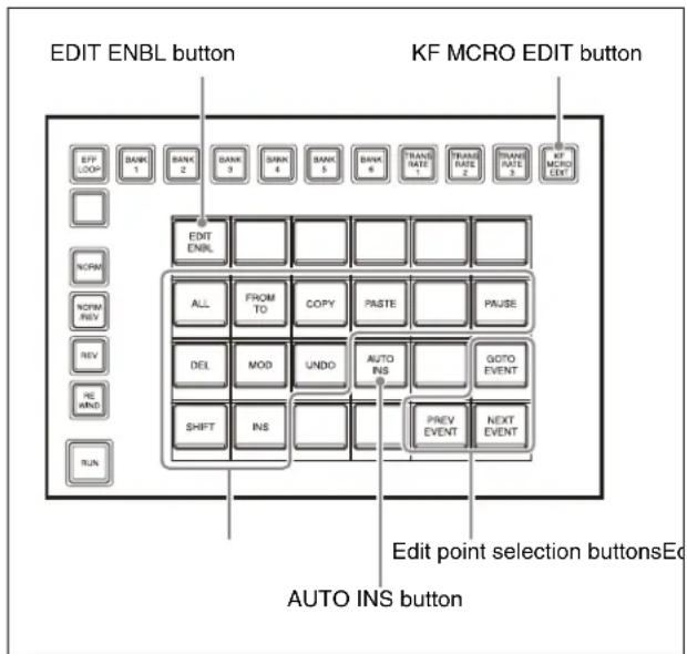
Pressing the [KF MCRO EDIT] button in the utility/shotbox control block, turning the [KF MCRO EDIT] button on amber, switches the memory recall section to effect timeline/macro edit mode.
Switching the numeric keypad control block to macro edit mode automatically activates macro edit mode in the utility/shotbox control block. You can create and edit a macro when the [EDIT ENBL] button is lit red.
Note
Creating/editing a macro is supported only when a macro register is recalled in macro operation mode in the numeric keypad control block.
Creating and Editing a Macro
Setting Auto Insert Mode
You can enable/disable auto insert mode in the utility/shotbox control block in effect timeline/macro edit mode.
For details about auto insert mode, see “Auto insert mode” (page 315).
To enable auto insert mode, press the [AUTO INS] button, turning it on orange.
To disable auto insert mode, press the [AUTO INS] button, turning it on dark blue.
When you start creating or editing a macro with the macro execution mode set to normal execution mode, auto insert mode is automatically enabled.
To Set Auto Pause Insert Mode
To enable auto pause insert mode, press and hold the [AUTO INS] button. The [AUTO INS] button indication changes to [AUTO PAUSE] button, and turns on blue.
To disable auto insert mode and auto pause insert mode, press and hold the [AUTO PAUSE] button until the indication returns to [AUTO INS] button.
Creating/Editing a Macro
Note
Menu operation events cannot be registered using the utility/shotbox control block or numeric keypad control block.
1 Press the [MCRO] button in the numeric keypad control block.
The [MCRO] button and [RCALL] button turn on amber, and the numeric keypad control block switches to macro operation mode.
2 Enter a register number in the numeric keypad area and press the [ENTER] button.
For details about selecting a register, see “Selecting a register” (page 266).
When creating a macro
Select an empty register. The numeric keypad control block automatically switches to macro edit mode.
When editing a macro
Select the target register to edit. Press and hold the [MCRO] button and press the [STORE] button to switch the numeric keypad control block to macro edit mode.
For details about edit mode in the numeric keypad control block, see “Edit mode” (page 320).
3 Press the [KF MCRO EDIT] button in the utility/shotbox control block.
The memory recall section switches to effect timeline/macro edit mode.
When the numeric keypad control block is set to macro edit mode, the utility/shotbox control block also automatically switches to macro edit mode and the [EDIT ENBL] button turns on red.
4 If required, set auto insert mode.
For details about setting auto insert mode, see "Setting auto insert mode" (page 321).
5 Register/edit events.
When creating a macro
Perform an operation to register as an event in a macro.
You can also register pause events.
For details about pause events, see “Inserting a pause event” (page 322).
When auto insert mode is enabled, events are registered automatically.
When auto insert mode is disabled, press the [INS] button in the utility/shotbox control block to register an event.
Repeat the operation as required to register events. The events are registered in the macro in the order the operations are performed.
When editing a macro
You can edit an event using the buttons in the memory recall section in the utility/shotbox control block.
For details, see "Editing a Macro Event" (page 322).
Note
During macro creation/editing, if you press any of the mode selection buttons in the numeric keypad control block other than the [MCRO] button, the executed operation is also registered as an event.
You can also perform effect timeline operations using the following buttons in the utility/shotbox control block.
[EFF LOOP], [NORM], [NORM/REV], [REV], [REWIND], [RUN]
6 Press the [STORE] button in the numeric keypad control block and enter the target register number in which to save.
The currently recalled register number is displayed on the display. To select another register, enter a register number.
For details about selecting a register, see “Selecting a register” (page 266).
7 Press the [ENTER] button.
The created/edited macro is saved in the register, and the [STORE STATS] button and [RCALL] button turn on amber.
To undo saving a macro
While the [STORE STATS] button is lit amber, press and hold the [STORE STATS] button and press the [UNDO] button.
Editing a Macro Event
You can edit a macro event by switching the utility/shotbox control block to effect timeline/macro edit mode.
Selecting an edit point
Move to the target event (edit point) to edit in the macro.
To move to the previous event
Press the [PREV EVENT] button in the utility/shotbox control block.
To move to the next event
Press the [NEXT EVENT] button in the utility/shotbox control block.
To move to a specified event number
Press the [GOTO EVENT] button in the utility/shotbox control block, enter an event number in the numeric keypad area of the numeric keypad control block, and press the [ENTER] button.
Inserting an event
1 Select an edit point.
2 Perform an operation to register as an event.
When auto insert mode is enabled, the event is inserted after the selected event automatically. When auto insert mode is disabled, press the [INS] button in the utility/shotbox control block to insert an event. When you press the [INS] button, an event is inserted after the selected event. When you press and hold the [SHIFT] button and press the [INS] button, the event is inserted before the selected event.
Inserting a pause event
For details about pause events, see “Pause event” (page 315).
1 Select an edit point.
2 Press the [PAUSE] button, turning it on blue, in the utility/shotbox control block.
3 Enter a pause time in the numeric keypad area in the numeric keypad control block and press the [ENTER] button.
The color of the [PAUSE] button in the utility/shotbox control block changes to orange.
When auto insert mode is enabled, the pause event is inserted after the selected event automatically. When auto insert mode is disabled, press the [INS] button in the utility/shotbox control block to insert a pause event. When you press the [INS] button, a pause event is inserted after the selected event. When you press and hold the [SHIFT] button and press the [INS] button, the event is inserted before the selected event.
Note
When auto pause insert mode is enabled, the [PAUSE] button operation inserts a pause event only. Another pause event is not inserted automatically between the pause event inserted using the [PAUSE] button and the next event.
Modifying an event
1 Select an edit point.
2 Disable auto insert mode if it is enabled.
3 Perform an operation to register as an event.
4 Press the [MOD] button in the utility/shotbox control block.
The selected event is modified.
Note
You can also select and modify multiple events.
For details, see “Selecting multiple events” (page 323).
Deleting an event
1 Select an edit point.
2 Press the [DEL] button in the utility/shotbox control block.
The selected event is deleted.
Note
You can also select and delete multiple events.
For details, see "Selecting multiple events" (page 323).
To move an event
Delete an event, select an edit point, and press the [PASTE] button.
The deleted event is inserted after the selected event.
To insert before the selected event, press and hold the [SHIFT] button and press the [PASTE] button.
Copying an event
1 Select a copy source edit point.
2 Press the [COPY] button in the utility/shotbox control block.
3 Select a copy destination edit point.
4 Press the [PASTE] button in the utility/shotbox control block.
The copied event is inserted after the selected event. To insert before the selected event, press and hold the [SHIFT] button and press the [PASTE] button.
Note
You can also select and copy multiple events.
For details, see "Selecting multiple events" (page 323).
Selecting multiple events
You can select multiple events as the edit target. This operation is available when modifying, deleting, or copying an event.
To select all events
Press the [ALL] button, turning it on orange, in the utility/shotbox control block.
To select multiple events within a specified range
1 Select the first event for a specified range.
2 Press the [FROM TO] button in the utility/shotbox control block.
"FROM XXX TO" ("XXX" is the current event number) is displayed on the display in the numeric keypad control block.
3 Enter the number of the last event for the specified range in the numeric keypad area in the numeric keypad control block.
To change the number of the first event in the specified range, press the [CLR] button. Enter the number of the first event, press the [ENTER] button, and then enter the number of the last event.
Note
Enter a “.” (period) to specify a range from the first event to the last event.
If the last event is not specified, the range up to the last event becomes the specified range.
4 Press the [ENTER] button.
The specified range is applied.
Merging registers
You can insert all events from another register at a specified position.
1 Select an edit point.
2 Enable auto insert mode.
Note
Registers cannot be merged when auto insert mode is disabled.
3 Recall a register to merge.
Recall a macro register using one of the following buttons.
- Buttons with a set macro attachment (see page 336)
• Cross-point buttons in the cross-point control block (see page 330)
- Buttons in cross-point pad in the cross-point control block/AUX bus control block (see page 330)
• Memory recall buttons in the Flexi Pad control block (see page 329)
- Buttons in the numeric keypad area in the numeric keypad control block (see page 330)
4 Press the [PASTE] button in the utility/shotbox control block.
All events in the recalled register are inserted after the selected event.
To insert before the selected event, press and hold the [SHIFT] button and press the [PASTE] button.
Undoing an edit operation
To undo an operation immediately after inserting, modifying, or pasting an event, press the [UNDO] button in the utility/shotbox control block.
Macro Operations (Menu)
Macro edit mode
You can create and edit a macro using the Home >
Register > Macro > Edit Macro menu (18307.11).
Operations performed in macro edit mode using the menu or a panel can be registered in a macro as an event.
Multiple simultaneous MLS-X1 menu client connections are supported, but only one web menu client can edit a macro at any given time.
When an operation that would invoke edit mode is performed while editing a macro in another menu client, the macro being edited in the other menu client is saved and then the mode switches to edit mode.
In macro edit mode, the following information is displayed in the header area. This display also acts as a button, and pressing the button opens the Home >
Register > Macro > Edit Macro menu (18307.11).
Menu Macro Enbl: When auto insert mode is disabled during macro editing
You can execute a macro using panel operations.
Macro Auto Ins: When auto insert mode is enabled during macro editing
When you recall a macro register using a panel operation, all events of the target register are inserted into the register being edited.
Macro Rcl Proh.: Displayed if macro execution is prohibited under the following conditions.
- When editing a macro using a panel
- In menus not in macro edit mode, when multiple menus are open and auto insert mode is enabled in a menu in macro edit mode
Notes
- A macro cannot be created/edited using the menu when the Flexi Pad control block or numeric keypad control block macro operation mode is in edit mode.
- When executing a macro, if you switch to macro edit mode, the macro currently being executed stops.
- Multiple simultaneous MLS-X1 menu client connections are supported, but only one of the following pop-up windows can be displayed at any given time.
Whenever any pop-up window is displayed, the window previously opened using another menu client is closed.
– [Recall/Store Register] window: Displayed using the [Recall/Store] button on the [Effect Timeline Recall/Store] taskbar, [Effect Timeline Edit] taskbar, or [Snapshot] taskbar
– [Edit Timeline] window: Displayed using the [All Edit Options] button on the [Effect Timeline Edit] taskbar
- [Edit Macro Event] window:
Displayed using the [All Edit Options] button in the [Edit] group in the Home > Register > Macro > Edit Macro menu (18307.11)
- When the [Edit Macro Event] window is displayed, switching to an operation mode other than macro operation mode using the mode selection buttons in the numeric keypad control block closes the [Edit Macro Event] window.
Creating and Editing a Macro
1 Open the Home > Register > Macro > Edit Macro menu (18307.11).
2 Press the [Register No.] button and enter a register number in the numeric keypad window.
When creating, select an empty register. When editing, select the target register to edit.
The [Start Editing] button changes to an [Exit] button and macro edit mode is activated.
If the contents of the register to edit are already displayed when the menu is opened in step 1, press the [Start Editing] button to switch to edit mode.
When editing a macro in another menu session or control panel
A message appears when you enter the register number. Press [OK] to switch to macro edit mode.
3 Press the [Register Name] button and enter a name (up to 8 characters) using the keyboard window, as required.
4 If required, set auto insert mode.
To enable auto insert mode, set the [Auto Insert] button in the [Edit] group to the on state.
To disable auto insert mode, set the [Auto Insert] button in the [Edit] group to the off state.
For details about auto insert mode, see “Auto insert mode” (page 315).
Notes
- Auto pause insert mode cannot be set using the menu.
- Pressing the [All Edit Options] button in the [Edit] group displays the [Edit Macro Event] window.
You can also set auto insert mode using the [Auto Insert] button in the [Edit Macro Event] window.
5 Register/edit events.
When creating a macro
Create and register events.
For details about registering events, see “Inserting an event” (page 318).
You can also register pause events.
For details about registering pause events, see "Inserting a pause event" (page 327).
Repeat the operation as required to register events.
When editing a macro
Perform event edit operations.
For details, see "Editing a Macro Event" (page 325).
6 Press the [Store] button and enter the target register number in which to save in the numeric keypad window.
The currently recalled register number is displayed in the numeric keypad window. To select another register, enter a register number.
Press [Enter] to confirm to save the created/edited macro in the register.
To exit macro edit mode without saving
Press the [Exit] button, check the message, then press [OK].
Editing a Macro Event
Select the target register to edit in the Home > Register > Macro > Edit Macro menu (18307.11) to switch to edit mode and edit an event. When finished editing, save the register.
For details, see “Creating and Editing a Macro” (page 325).
You can edit an event using the following menu or the taskbar.
Home > Register > Macro > Edit Macro menu (18307.11)
Event list at the top:
Displays the events registered in the selected register. Select an event insertion position and target event to edit from the list.
You can check the following information.
• Number and name of register being edited
- Event number
- Event type
Displays "Event" or "Continue."
- Symbol
Displays the symbol name of an event.
- Data
Displays the parameter setting values.
- Parameters
Displays the selected event number and the configured parameter names below the list.
Operation buttons at the bottom:
Perform edit operations using the [Add New Event] button, [Edit Event] button, and buttons in the [Edit] group.
Pressing the [All Edit Options] button in the [Edit] group displays the [Edit Macro Event] window.
The buttons used for editing are shown on the left and a numeric keypad area is shown on the right in the [Edit Macro Event] window.
[Macro Edit] taskbar
You can display the following information and perform the following operations using the [Macro Edit] taskbar.
• Number and name of register being edited
- Selected event number and total number of events
- Symbols and data for the last event operated from a panel or menu while editing a macro
A “...” suffix is displayed when the whole data cannot be displayed.
Press the event data display to display the whole event data. To return to the previous display, press [OK].
• [Event – Insert After] button
Inserts the current event after the selected event.
- [Edit Macro] button
Recalls the Home > Register > Macro > Edit Macro menu (18307.11).
Notes
- If a macro is executed using panel operations while editing a macro event in the menu, information about the menu editing will be displayed on the [Macro Edit] taskbar.
- When multiple menus are open, the same register information is displayed in all menus.
Event structure
A macro event consists of an “Event” or “Continue” type, symbol, and parameters.
Specify the event type using “Event” or “Continue.” Use “Continue” when you want to add another parameter to the symbol and parameters set for “Event.”
Select a type of event according to the symbol and specify the required data using the parameters.
For details about symbols and parameters, see “Events and Symbols” (page 564) and “Symbols and Parameters” (page 565).
Notes
- Selecting an “Event” event as the target to edit also selects the subordinate “Continue” events.
- “Continue” may not be supported depending on the symbol.
Inserting an event
Create and register events.
1 In the event list, select the event at the insertion position.
2 Press the [Add New Event] button.
The [Add New Event] window appears.
3 Select a type of event.
To insert “Event,” set the [Event] radio button to the on state.
To insert “Continue,” set the [Continue] radio button to the on state.
An [Event] button or [Continue] button is added at the start of the [Symbol/Parameter] group.
Note
When inserting at the top of the list, [Continue] cannot be selected.
4 Press the [Event] button or [Continue] button in the [Symbol/Parameter] group.
The [Symbol] window appears.
5 Press the button for the target symbol to set.
Select a tab to change the event to display.
[A to I] tab: Symbols whose name starts with A to I [J to R] tab: Symbols whose name starts with J to R [S to Z] tab: Symbols whose name starts with S to Z
Note
When inserting “Continue,” only the symbol that is the same as the event at the selected insertion position can be set.
6 Press [OK].
The required parameter buttons for the selected symbol are added to the [Symbol/Parameter] group in the [Add New Event] window.
7 Set the parameters.
When a parameter button is pressed, select/enter a parameter setting value using a selection window, numeric keypad window, or the keyboard.
8 Press [OK] in the [Add New Event] window.
When auto insert mode is enabled, the event is inserted after the selected event automatically. When auto insert mode is disabled, press the [Event – Insert After] button to insert the event.
Note
You can insert before or after the selected event using the [Insert Before] button or [Insert After] button in the [Edit Macro Event] window.
To insert a control panel operation event
1 In the event list, select the event at the insertion position.
2 Perform a control panel operation to register as an event.
When auto insert mode is enabled, the control panel operation is inserted as an event after the selected event automatically.
When auto insert mode is disabled, press the [Event - Insert After] button to insert the control panel operation as an event.
Note
You can insert before or after the selected event using the [Insert Before] button or [Insert After] button in the [Edit Macro Event] window.
To insert a menu operation event
1 In the event list, select the event at the insertion position.
2 Perform a menu operation to register as an event.
When auto insert mode is enabled, the menu operation is inserted as an event after the selected event automatically.
When auto insert mode is disabled, press the [Event - Insert After] button to insert the menu operation as an event.
Note
You can insert before or after the selected event using the [Insert Before] button or [Insert After] button in the [Edit Macro Event] window.
Inserting a pause event
For details about pause events, see “Pause event” (page 315).
1 In the event list, select the event at the insertion position.
2 Press the [Pause] button in the [Edit] group and enter a pause time in the numeric keypad window.
Note
You can also set this using the [Pause] button in the [Edit Macro Event] window. Enter a pause time in the numeric keypad area.
3 Press [Enter].
When auto insert mode is enabled, the pause event is inserted after the selected event automatically. When auto insert mode is disabled, press the [Event - Insert After] button to insert the pause event.
Note
You can insert before or after the selected event using the [Insert Before] button or [Insert After] button in the [Edit Macro Event] window.
Modifying an event
Note
Menu operation events cannot be modified.
1 In the event list, select the target event to modify. 2 Press the [Edit Event] button. The [Edit Event] window appears. 3 Modify the event. Modify the “Event” or “Continue” type, symbol, and parameters in the same way as when creating an event in the [Add New Event] window. For details, see “Inserting an event” (page 326). 4 Press [OK] in the [Edit Event] window. The selected event is modified.
To modify an event using a control panel operation
1 In the event list, select the target event to modify. 2 Perform a control panel operation to register as an event. 3 In the [Edit Macro Event] window, press the [Modify] button. The selected event is modified.
Deleting an event
1 In the event list, select the target event to delete.
2 Press the [Delete] button in the [Edit] group.
The selected event is deleted.
Notes
- You can also use the [Delete] button in the [Edit Macro Event] window.
- You can also select and delete multiple events. For details, see “Selecting multiple events” (page 328).
To move an event
Delete an event, select the event at the insertion position, and press the [Paste Before] button or [Paste After] button in the [Edit Macro Event] window.
The deleted event is inserted before or after the selected position.
Copying an event
1 In the event list, select a copy source event. 2 Press the [Copy] button. 3 In the event list, select the event at the insertion position. 4 Press the [Paste Before] button or [Paste After] button.
The copied event is inserted before or after the selected event.
Note
You can also select and copy multiple events.
For details, see “Selecting multiple events” (page 328).
Selecting multiple events
You can select multiple events as the edit target. This operation is available when deleting or copying an event.
To select all events
In the [Edit Macro Event] window, set the [All] button to the on state.
To select multiple events within a specified range
1 In the event list, select the first event for a specified range.
2 In the [Edit Macro Event] window, press the [From To] button.
“From XXX To” (“XXX” is the current event number) is displayed on the numeric keypad area display.
3 Enter the number of the last event for the specified range in the numeric keypad area.
To change the number of the first event in the specified range, press [Clear]. Enter the number of the first event, press [Enter], and then enter the number of the last event.
Enter a “.” (period) to specify a range from the first event to the last event.
4 Press [Enter].
The specified range is applied.
Merging registers
You can insert all events from another register at a specified position.
1 In the event list, select the event at the insertion position. 2 In the [Edit Macro Event] window, press the [Merge] button. 3 Enter the number of a register to merge in the numeric keypad area. 4 Press [Enter].
All events in the register are inserted after the selected position.
Undoing an edit operation
To undo an operation immediately after inserting, modifying, or pasting an event, press the [Undo] button in the [Edit Macro Event] window.
Executing a Macro
You can execute a macro using the Flexi Pad control block, utility/shotbox control block, utility control block, cross-point control block, or numeric keypad control block.
On the utility/shotbox control block, utility control block, and cross-point control block, use buttons assigned with the macro register recall function.
For details about assigning a function, see “Assigning a Utility Function” (page 431).
Executing a Macro (Flexi Pad Control Block)
You can recall a macro register and execute a macro on the Flexi Pad control block in macro operation mode. The macro execution operation varies depending on the execution mode.
For details about the execution mode, see “Macro execution mode” (page 315).
Notes
- If the same macro or another macro is recalled during macro execution or when the macro is stopped, the operation varies depending on the settings. For details about settings, see “Setting the Macro Mode” (page 447).
- Events registered in a macro are executed according to the setup and the device configuration in force when the events were registered. If the state has changed since registration, the contents of the macro may not be reproduced correctly when the macro is recalled.
- When executing a macro, if you switch to macro edit mode, the macro currently being executed stops.
- A macro cannot be executed while creating/editing a macro using panel operations.
Executing a macro in normal execution mode
1 Press the [MCRO] button.
The [MCRO] button is lit amber, and the memory recall section switches to macro operation mode.
2 Select a bank.
For details about selecting a bank, see “Selecting a bank” (page 317).
3 Press the button for the target register to recall.
For details about selecting a register, see “Selecting a register” (page 317).
The register button is lit orange and the macro is executed.
The number of executed events and total number of events are displayed on the bottom center button in the memory recall section.
To resume when paused by a pause event
When paused by a pause event with a specified pause time of “0”, the [TAKE] button is displayed in the memory recall section.
Press the [TAKE] button to resume macro execution.
Executing a macro in step execution mode
1 Press the [MCRO] button.
The [MCRO] button is lit amber, and the memory recall section switches to macro operation mode.
2 Select a bank.
For details about selecting a bank, see “Selecting a bank” (page 317).
3 Press the button for the target register to recall.
For details about selecting a register, see “Selecting a register” (page 317).
The register button is lit orange.
4 Press the [TAKE] button in the memory recall section.
A single event registered in the macro is executed, then execution stops.
Press the [TAKE] button to execute events one at a time.
The number of executed events and total number of events are displayed on the bottom center button in the memory recall section.
Executing a Macro (Utility/Shotbox Control Block)
You can recall a macro using the memory recall section in a utility/shotbox control block assigned to a bank.
1 Select a bank.
For details about selecting a bank, see “Selecting a bank” (page 243).
2 Press the button for the target register to recall.
When a button assigned with a macro register is pressed, the button is lit orange and the macro is recalled.
In normal execution mode, the macro is executed automatically.
Executing a Macro (Utility Control Block)
You can recall a macro using the utility control block in utility/shotbox operation mode.
1 Press the [UTIL/SBOX] button.
The memory recall section switches to utility/shotbox operation mode.
2 Select a bank.
For details about selecting a bank, see “Selecting a bank” (page 244).
3 Press the button for the target register to recall.
When a button assigned with a macro register is pressed, the button is lit orange and the macro is recalled.
In normal execution mode, the macro is executed automatically.
Executing a Macro (Cross-Point Control Block)
You can recall a macro using a cross-point button row assigned with a utility/shotbox bank.
1 Select a bank.
The target utility/shotbox bank is assigned to a cross-point button row.
For details about selecting a bank, see “Selecting a bank” (page 244).
2 Press the button for the target register to recall.
When a button assigned with a macro register is pressed, the button is lit amber and the macro is recalled.
In normal execution mode, the macro is executed automatically.
To recall a macro using cross-point pad buttons
You can assign the macro register recall function to buttons in the cross-point pad of a cross-point control block/AUX bus control block on the ICP-X7000.
Press the button for the target register to recall the macro.
For details about assigning buttons, see “Setting a Cross-Point Pad” (page 436).
Executing a Macro (Numeric Keypad Control Block)
You can recall a macro using the numeric keypad control block in macro operation mode.
1 Press the [MCRO] button.
The [MCRO] button and [RCALL] button turn on amber, and the numeric keypad control block switches to macro operation mode.
2 Enter the target register number to recall in the numeric keypad area and press the [ENTER] button.
For details about selecting a register, see “Selecting a register” (page 266).
The macro is recalled.
In normal execution mode, the macro is executed automatically.
If the macro is interrupted during macro execution, the [RCALL] button flashes amber.
Macro Register Operations
Displaying a Macro Register
Open the Home > Register > Macro > Edit Register > Browse menu (18307.21).
- Register number
- Register name
- Lock icon
A lock icon is displayed when a register is locked.
Editing icon
An editing icon is displayed when a register is being edited.
When the [Edit Macro] button is pressed, the Home > Register > Macro > Edit Macro menu (18307.11) is recalled.
For details, see “Creating and Editing a Macro” (page 325).
To search for a register
Press the [Search] button, enter a character string to search for in the input field in the displayed window, and press the [Enter] button.
Only registers containing the entered character string are displayed.
Editing a Macro Register
You can copy, move, and swap register data. You can also rename, lock, and delete a register.
Copying a register
Notes
- An empty register cannot be copied.
- A locked register cannot be copied.
1 Open the Home > Register > Macro > Edit Register > Copy/Move/Swap menu (18307.22).
A list of copy source registers is shown on the left, and a list of copy destination registers is shown on the right.
2 In the list on the left, select a copy source register.
To select and copy multiple registers, place a check mark beside the target registers to copy. To select and copy all registers, place a check mark in the 'select all' checkbox.
You can also press the [Select Register(s)] button and enter a register number in the numeric keypad window.
3 In the list on the right, select a copy destination register.
When multiple registers are selected, select the first copy destination register.
You can also press the [Select Destination] button and enter a register number in the numeric keypad window.
The copy destination of the first register selected on the left is the first register selected on the right, and the subsequent registers on the right in the same relative positions as the selected registers on the left become copy destinations. The first register on the right is shown in light blue, and the subsequent copy destination registers are shown in blue gray.
4 Press the [Copy] button.
5 Check the message, then press [OK].
To search for a register
Press the [Search] button, enter a character string to search for in the input field in the displayed window, and press the [Enter] button.
Only registers containing the entered character string are displayed.
To copy without renaming a destination register
Set the [w/o Name] button to the on state.
Moving a register
Notes
- An empty register cannot be moved.
- A locked register cannot be moved.
Select a move source register and move destination register in the same way as for copying a register and press the [Move] button.
For details, see "Copying a register" (page 331).
To move without renaming a destination register
Set the [w/o Name] button to the on state.
Swapping registers
Select the registers to swap in the same way as for copying a register and press the [Swap] button.
For details, see "Copying a register" (page 331).
To swap without renaming the registers
Set the [w/o Name] button to the on state.
Locking a register
1 Open the Home > Register > Macro > Edit Register > Browse menu (18307.21). 2 Select the target register to lock.
To select and lock multiple registers, place a check mark beside the target registers to lock.
To select and lock all registers, place a check mark in the 'select all' checkbox.
You can also press the [Select Register(s)] button and enter a register number in the numeric keypad window.
3 Press the [Lock] button.
To release the lock
Select the target register to unlock and press the [Unlock] button.
Deleting a register
Note
A locked register cannot be deleted.
1 Open the Home > Register > Macro > Edit Register > Browse menu (18307.21). 2 Select the target register to delete.
To select and delete multiple registers, place a check mark beside the target registers to delete.
To select and delete all registers, place a check mark in the 'select all' checkbox.
You can also press the [Select Register(s)] button and enter a register number in the numeric keypad window.
3 Press the [Delete] button. 4 Check the message, then press [OK].
Renaming a register
Note
A locked register cannot be renamed.
1 Open the Home > Register > Macro > Edit Register > Browse menu (18307.21). 2 Select the target register to rename.
To select and rename multiple registers, place a check mark beside the target registers to rename.
To select and rename all registers, place a check mark in the 'select all' checkbox.
You can also press the [Select Register(s)] button and enter a register number in the numeric keypad window.
3 Press the [Register Name] button and enter a name (up to 8 characters) using the keyboard.
Macro Attachments
Overview
A macro attachment is a function whereby a macro register is assigned to a control panel button or a particular position of a fader lever, linking the execution of the button function or a fader lever operation with a macro execution.
Macro attachment link mode
The following three link modes are available.
Pre-macro mode: The macro is executed first, and then the button function is executed.
Post-macro mode: The button function is executed first, and then the macro is executed.
Macro only mode: The button function is not executed, and only the macro is executed.
To set a link mode, use the following buttons.
- [PRE MACRO] button assigned to the cross-point pad/function button section in the cross-point control block
- [POST MACRO] button assigned to the cross-point pad/function button section in the cross-point control block
- Button assigned with the "Pre Macro" utility command
- Button assigned with the "Post Macro" utility command
Setting a macro attachment
Only one register can be assigned to a button.
You can set a macro attachment to the following buttons.
| Control block Button | |
| Cross-point control block | Cross-point buttons of the bus assigned to the 1st row to 4th row a) b) |
| AUX bus control block (AUX bus operation mode) | Cross-point buttons of the bus assigned to the 3rd row/4th row a) b) |
| Transition control block | Fader leverButtons assigned with the following functions.- Auto transition- Cut- Select next transition- Select transition type- Enable/disable pattern limit- Auto transition in an independent key transition c)- Key on/off in an independent key transitionc) |
| Control block Button | |
| Transition control block (simple type) | Fader leverButtons assigned with the following functions.— Auto transition— Cut— Select transition type— Enable/disable pattern limit |
| Independent key transition control block | Buttons assigned with the following functions.— Auto transition in an independent key transition c — Key on/off in an independent key transition c |
| Key fader control block | Buttons assigned with the following functions.— Select transition type— Auto transition in an independent key transition c — Key on/off in an independent key transition c |
| Device control block | [CUE] button[PLAY] button[STOP] button[START TC] button |
a) You can set a separate macro attachment for each bus. b) You can also set a macro attachment to buttons with inhibit enabled. c) In the case of an event that inserts or removes a key, the state at the time of event registration (key on or key off) is also registered in the macro. When a macro is executed, the event is only reproduced if the key state matches the registered state.
Notes
- After setting a macro attachment to a 2nd row cross-point button in the cross-point control block in key/AUX bus delegation mode, if you change the bus assignment of the 1st row delegation buttons, the macro attachment setting is deleted.
- After setting a macro attachment to a 3rd row/4th row cross-point button in the AUX bus control block (AUX bus operation mode), if you change the bus assignment of the 1st row/2nd row delegation buttons, the macro attachment setting is deleted. • After setting a macro attachment to an assignable button, if you change the button setting, the macro attachment setting is deleted.
- After setting a macro attachment to a cross-point button in the cross-point control block, if you change the function assignment of the button, the macro attachment setting is deleted.
Executing a macro attachment
To execute a macro assigned to a button or fader lever using a macro attachment, macro attachments must be enabled.
You can enable/disable macro attachments using the following buttons.
- ICP-X7000: [MACRO ATTACH ENABLE] button assigned to the cross-point pad in the cross-point control block
- ICP-X1000 series: [MCRO ATTCH E NBL] button assigned to the function button section in the cross-point control block
- Button assigned with the “Macro Attachment Enbl” utility command You can also permanently enable or disable macro attachments.
For details about settings, see “Setting the macro attachment enable/disable configuration mode” (page 448).
Setting a Macro Attachment
Selecting a macro register
You can select a macro register to assign to a control panel button or a fader lever.
1 Open the Home > Register > Macro > Attachment menu (18307.31).
2 Press the [Target Register] button and enter a register number in the numeric keypad window.
Note
When a macro register is recalled using a control panel, the register number of the recalled register is set.
For details about recalling a macro register, see "Executing a Macro" (page 329).
Setting a macro attachment to a button
1 Select a macro register.
For details about selecting a register, see “Selecting a macro register” (page 334).
2 Assign a macro register to a button.
To assign in pre-macro mode
Press and hold the [PRE MACRO] button in the cross-point control block and press the assignment target button.
To assign in post-macro mode
Press and hold the [POST MACRO] button in the cross-point control block and press the assignment target button.
To assign in macro only mode
Simultaneously press and hold both the [PRE MACRO] button and [POST MACRO] button in the cross-point control block and press the assignment target button.
Notes
- When a button assigned with a macro attachment is selected, the newest configured macro attachment setting becomes enabled.
- When setting a macro attachment, the button function is not executed. You can also configure a setting such that the button function is executed. For details about settings, see “Setting the operation of buttons when configuring a macro attachment” (page 448).
- You can also use buttons assigned with the “Pre Macro” utility command/“Post Macro” utility command instead of the [PRE MACRO] button/[POST MACRO] button.
To check the macro attachment setting status
You can check the cross-point buttons in a cross-point control block for which a macro attachment is set. While the [PRE MACRO] button is pressed, the buttons for which a macro attachment is set flash as follows. Buttons set in pre-macro mode: Flash amber. Buttons set in macro only mode: Flash green. While the [POST MACRO] button is pressed, the buttons for which a macro attachment is set flash as follows. Buttons set in post-macro mode: Flash amber. Buttons set in macro only mode: Flash green.
Setting a macro attachment to a fader lever
You can set a macro attachment to any particular position of a fader lever in the transition control block/transition control block (simple type).
Note
Macro link mode is enabled only when a macro attachment is set to the operation start point (0%) or operation end point (100%) of the fader lever.
To set at the operation start point, assign a macro register in pre-macro mode. To set at the operation end point, assign a macro register in post-macro mode.
It is not possible to set a macro attachment in macro only mode.
1 Select a macro register.
For details about selecting a register, see “Selecting a macro register” (page 334).
2 Move the fader lever to the position where you want to set a macro attachment.
3 Assign a macro register to the fader lever.
To assign to a position other than the operation start point/operation end point
Press and hold the [PRE MACRO] button or [POST MACRO] button in the cross-point control block and press the [LIMIT SET] button or [PRIOR SET] button in the transition control block/transition control block (simple type).
To assign to the operation start point
Press and hold the [PRE MACRO] button in the cross-point control block and press the [LIMIT SET] button or [PRIOR SET] button in the transition control block/transition control block (simple type).
To assign to the operation end point
Press and hold the [POST MACRO] button in the cross-point control block and press the [LIMIT SET] button or [PRIOR SET] button in the transition control block/transition control block (simple type).
Notes
- On the transition control block (simple type), the [PRIOR SET] button cannot be used.
- You can also use buttons as signed with the “Pre Macro” utility command/“Post Macro” utility command instead of the [PRE MACRO] button/[POST MACRO] button.
To check the macro attachment setting status
You can check the fader lever position at which the macro attachment is set.
While the [PRE MACRO] button or [POST MACRO] button in the cross-point control block is pressed, the status is displayed in the transition control block/ transition control block (simple type) as follows. Transition indicator: The indicators at the position where the macro attachment is set and at both ends are lit. Display 1) : Displays the position where the macro attachment is set as a percentage (fader lever operation start position is 0%, operation end position is 100%).
1) ICP-X7000: The display in the transition execution section in the transition control block and the display in the transition control block (simple type). ICP-X1000 series: The display on the right side in the transition control block.
Releasing a macro attachment
To release a macro attachment set to a button
Press and hold the [PRE MACRO] button or [POST MACRO] button in the cross-point control block and press the target button to release.
To release a macro attachment set to a fader lever
Press and hold the [PRE MACRO] button or [POST MACRO] button in the cross-point control block and press the [LIMIT SET] button or [PRIOR SET] button in the transition control block/transition control block (simple type).
Note
You can also release a macro attachment setting using the menu.
For details, see “Displaying a Macro Attachment List” (page 336).
Setting the macro attachment configuration mode of a cross-point button
The following two modes can be selected for a macro attachment set to a cross-point button. Button number mode: Assign a macro attachment for the combination of bus and button number. Pair number mode: Assign a macro attachment for the combination of bus and logical V/K pair number.
Notes
- If the macro attachment configuration mode is changed, the macro attachment assigned to a cross-point button is deleted.
- In pair number mode, the following occurs.
- If the same logical V/K pair number is assigned to multiple cross-point buttons, pressing one of the buttons executes the macros of all buttons to which the same logical V/K pair number is assigned.
- If the same logical V/K pair number is assigned to multiple cross-point buttons, releasing the macro attachment of one of the buttons releases the macro attachment of all buttons to which the same logical V/K pair number is assigned.
- If you change the logical V/K pair number assignment to a different cross-point button, the macro attachment setting is also transferred.
- When macro attachment data is loaded, the button number mode or pair number mode setting is overwritten.
1 Open the Home > Register > Macro > Attachment menu (18307.31).
2 In the [Xpt Attachment Mode] group, select a configuration mode.
Button Mode: Button number mode Pair Mode: Pair number mode
3 Check the message, then press [OK].
Displaying a Macro Attachment List
You can check the information for a button/fader lever to which a macro attachment is set in list view.
1. Open the Home > Register > Macro > Attachment menu (18307.31).
2. Display the target control block.
Select a tab to change the control block to display. [M/E-1] tab to [M/E-5] tab, [P/P] tab: Switcher bank cross-point control block and transition control block/transition control block (simple type)/independent key transition control block
[Aux] tab: AUX bus control block (ICP-X7000 only) [Trackball] tab: Device control block (ICP-X1000 series only)
[Trackball/Key Fader] tab: Device control block and key fader control block (ICP-X7000 only) A list of the macro attachments set to the buttons of the selected control block is displayed.
You can check the following information in a macro attachment list.
- Block name: Displays the name of the control block on which macro attachments are set.
- Buttons to which a macro attachment is set
- Register number
- Register name
- Link mode
For details about macro attachment lists, see “Macro Attachment Lists” (page 572).
Note
Macro attachments set to the following buttons in the cross-point control block may not be displayed in the list.
- DME utility 1 bus and 2 bus cross-point buttons in utility bus mode
- DME utility 1 bus and 2 bus cross-point buttons in key/AUX bus delegation mode
Releasing a macro attachment
1 Open the Home > Register > Macro > Attachment menu (18307.31). 2 Display the target control block.
Select a tab to change the control block to display.
[M/E-1] tab to [M/E-5] tab, [P/P] tab: Switcher bank cross-point control block and transition control block/transition control block (simple type)/independent key transition control block
[Aux] tab: AUX bus control block (ICP-X7000 only)
[Trackball] tab: Device control block (ICP-X1000 series only)
[Trackball/Key Fader] tab: Device control block and key fader control block (ICP-X7000 only)
3 Select the target button to release.
To select and release multiple buttons, place a check mark beside the target buttons to release. To select and release all buttons, place a check mark in the 'select all' checkbox.
4 Press the [Delete] button. 5 Check the message, then press [OK].
Releasing macro attachments on all control blocks
1 Open the Home > Register > Macro > Attachment menu (18307.31). 2 Press the [All Clear] button. 3 Check the message, then press [OK].
Executing a Macro Assigned in a Macro Attachment
You can execute a macro assigned to a control panel button or fader lever by enabling macro attachments.
Notes
- If the same button is pressed twice during macro execution or when the macro is stopped, or if another macro is recalled, the following operation depends on the settings.
For details about settings, see "Setting the Macro Mode" (page 447).
- Events registered in a macro are executed according to the setup and the device configuration in force when the events were registered. If the state has changed since registration, the contents of the macro may not be reproduced correctly when the macro is recalled.
- When executing a macro, if you switch to macro edit mode, the macro currently being executed stops.
- When creating/editing a macro, pressing a button or fader lever for which a macro attachment is set does not execute the macro.
Enabling macro attachments
You can enable/disable macro attachments using the following buttons.
To enable macro attachments assigned on a control block of a switcher bank
Press the one of the following buttons, turning it on, in the target switcher bank.
- ICP-X7000: [MACRO ATTACH ENABLE] button assigned to the cross-point pad in the cross-point control block
- ICP-X1000 series: [MCRO ATTCH E NBL] button assigned to the function button section in the cross-point control block
To disable, press the [MACRO ATTACH ENABLE] button/[MCRO ATTCH ENBL] button, turning it off.
To enable macro attachments assigned on a control block separate from a switcher bank
Enable using the following buttons assigned with the "Macro Attachment Enbl" utility command.
- Press a memory recall button in the utility/shotbox control block, turning it on orange. To disable, press the button, turning it on dark blue.
- Press a memory recall button in the utility control block, turning it on orange. To disable, press the button, turning it on dark blue.
- Press a cross-point button in the cross-point control block, turning it on amber. To disable, press the button, turning it off.
Note
You can also permanently enable or disable macro attachments.
For details about settings, see “Setting the macro attachment enable/disable configuration mode” (page 448).
Executing a macro assigned to a button
Note
When macro attachments are enabled, the cross-point buttons in a cross-point control block for which a macro attachment is set are lit green. You can also configure a setting so the buttons do not light up.
For details about settings, see “Lighting buttons configured with a macro attachment” (page 448).
1 Enable macro attachments.
For details, see “Enabling macro attachments” (page 337).
2 Press the button with a set macro attachment.
The macro is executed according to the link mode. During macro execution, the selected button flashes.
Executing a macro assigned to a fader lever
1. Enable macro attachments.
For details, see “Enabling macro attachments” (page 337).
2. Operate the fader lever.
A macro is executed when the fader lever passes the position at which the macro attachment is set.
Notes
- If you do not move the fader lever to the operation end position, the macro cannot be executed again.
- If executing a 2-stroke preset color mix, the macro is executed by fader lever operation in the first stroke. The macro is not executed by fader lever operation in the second stroke.
Macro Timelines
Overview
A macro timeline is an effect timeline for macros.
You can execute macros in sequence by setting macro recall/execute actions at keyframe points on an effect timeline.
There are 99 effect timeline registers that can be used in a macro region.
Notes
- Up to 99 macros can be executed simultaneously using a single macro timeline.
- If multiple macros are executed at the same time, the output may not be reproduced according to the timing registered in the macro timeline.
- Actions configured on a macro timeline are executed only when the macro timeline is operating in the normal direction. • The following cannot be set in a macro timeline.
- Keyframe loop
- Effect timeline loop
- Reverse direction execution – Normal/reverse direction execution
- Keyframe path
Macro timeline operations
You can operate a macro timeline using the [RUN] button/[REWIND] button in the utility/shotbox control block or utility control block, or the [Run] button/[Rewind] button in the menu.
Notes
- If a macro timeline has ended but a macro is still executing, you can press the [RUN] button/[REWIND] button or the [Run] button/[Rewind] button to terminate the macro timeline.
- In a macro timeline, since a take operation is not possible, if a pause event with a pause time of “0” is set in a registered macro, the actions after the pause are not executed. The macro timeline is terminated.
Creating a Macro Timeline
Setting an action
You can configure an action at a keyframe point on an effect timeline.
For details about setting an effect timeline, see "Effect Timeline Operations (Menu)" (page 272).
1. Open the Home > Register > Macro > Timeline > Action menu (18307.41). 2. In the [Action] group, select an action to set.
No Action: Do not set an action.
Recall: Recall a macro register.
Take: Execute a macro.
All Take: Execute all macros.
When the [Recall] button or [Take] button is selected, select the target register to recall/execute in the list on the right, and press the [Set] button.
To search for a register
Press the [Search] button, enter a character string to search for in the input field in the displayed window, and press the [Enter] button.
Only registers containing the entered character string are displayed.
Setting an action when rewind is executed
On a macro timeline, normally when the [REWIND] button is pressed, an action set for the first keyframe is not executed. When the [RUN] button is pressed, then the first keyframe action is executed.
To execute a specific action when the [REWIND] button is pressed, set a rewind action.
Note
The rewind action is enabled when you press the [REWIND] button, even if you have configured an action for the first keyframe to be executed after rewinding.
For details, see "Setting the operation of the first keyframe when rewind is executed" (page 447).
1 Open the Home > Register > Macro > Timeline > Rewind Action menu (18307.42). 2 In the [Action] group, select an action to set.
No Action: Do not set an action.
Recall: Recall a macro register.
When the [Recall] button is selected, select the target register to recall in the list on the right, and press the [Set] button.
To search for a register
Press the [Search] button, enter a character string to search for in the input field in the displayed window, and press the [Enter] button.
Only registers containing the entered character string are displayed.
Overview
Panel memory is a function that saves cross-point assign table settings and macro attachment assignments in a register in order to reproduce the same conditions.
The target is all M/E banks and AUX banks. Saving and recalling is not supported for individual banks.
Only the cross-point control block settings can be saved and recalled. The settings of all other control blocks are not targeted.
| Setup data Corresponding menu | |
| Table Assign Setup > Xpt Assign > TableAssign menu (19102.11) | |
| Operation Mode Setup > | Panel > Xpt Module >Operation Mode menu (19104.31) |
| Free Assign Setup > Panel | Xpt Module >Free Assign menu (19104.32) |
| Delegation Assign Setup | Panel > Xpt Module >Key Deleg / Aux Assign menu(19104.33) |
| Display Mode Setup > | Panel > Xpt Module >Display Mode menu (19104.34) |
| Xpt Pad Button Assign(ICP-X7000) | Setup > Panel > Xpt Module > XptPad Button Assign menu(19104.36) |
| Button Assign(ICP-X1000) | Setup > Panel > Module > ButtonAssign menu (19104.21) |
| Utility Function Assign Set | Setup > Panel > Module > UtilityFunction Assign menu (19104.22) |
| Macro Attachment Register | Macro > Attachmentmenu (18307.31) |
The following shows the initial status data restoration targets.
| Initial status data Restoration target | |
| Cross-point pad settings | The following items on all M/E rows• [MACRO ATTACH ENABLE] button• Display mode button• 1st row to 4th row delegation buttons• 1st row to 4th row cross-point assign table selection buttons• [DUAL BKGD BUS] button• [ROW-1 PROT] to [ROW-4 PROT] button• Cross-point pad display page numberThe following items on all AUX rows• Settings of delegation buttons assigned to the 1st row/2nd row• Settings of the following buttons assigned to the cross-point pad– Display mode button– [RTR MODE] button– [2ND DELG] button– [LEVEL BTN1] to [LEVEL BTN4] buttons• Cross-point pad display page number |
| Key/AUX bus delegation mode, delegation button settings | Key/AUX bus delegation mode, 1st row delegation button settings for all M/E rows |
Panel memory registers
There are 99 panel memory registers.
Panel Memory Operations (Flexi Pad Control Block)
You can recall and save panel memory in the Flexi Pad control block.
Memory recall section in panel memory operation mode
Pressing the [PNL MEM] button in the Flexi Pad control block switches the memory recall section to panel memory operation mode.
You can select registers (1 to 99) using the buttons in the memory recall section.
To allow operations on the 99 panel memory registers, the Flexi Pad control block groups the registers. A register group is called a bank.
There are ten banks (0 to 9) and you display and select the bank corresponding to the target register.
Ten registers are displayed in each bank. Bank 0 displays register numbers 1 to 9, bank 1 displays register numbers 10 to 19, and so on.
The currently selected bank number and register number are displayed on the top right button in the memory recall section.
Note
A register number is not assigned to the bottom left button of bank 0. You can assign any register number.
For details, see “Assigning a register to bottom left button of bank 0” (page 445).
Selecting a bank
You can switch banks using the following buttons.
To select bank 0: Press the [BANK0] button.
To select bank 1: Press the [BANK1] button.
To select bank 2: Press the [BANK2] button.
To select banks 0 to 9: Press the [BANK SEL] button and enter a bank number (0 to 9) using the numeric keypad in the memory recall section.
To select the previous bank, press the [PREV BANK] button in the memory recall section.
To select the next bank, press the [NEXT BANK] button in the memory recall section.
Selecting a register
The selected bank register is displayed in the memory recall section. Press the button for the target register to select it.
The register name or register number is displayed on buttons for registers with a registered panel memory.
The button color varies as follows, according to the register state.
Gray characters: Register not containing a registered panel memory
White characters: Register containing a registered panel memory
Lit orange: Last recalled register
Note
You can set the button display for registers with a registered panel memory to either the register name or register number. The register number is displayed if a register name has not been configured.
For details about setting the button display, see “Setting the button display in snapshot operation mode/panel memory operation mode/shotbox operation mode/macro operation mode” (page 445).
Recalling a Panel Memory
1 Press the [PNL MEM] button.
The memory recall section switches to panel memory operation mode.
2 Select a bank.
For details about selecting a bank, see “Selecting a bank” (page 340).
3 Select a register to recall a panel memory.
Press the button for the target register. The register button is lit orange and the panel memory is recalled.
Saving a Panel Memory
Set the state to save in a panel memory and use the following procedure to save in a panel memory register.
1 Press the [PNL MEM] button.
The memory recall section switches to panel memory operation mode.
2 Select a bank.
For details about selecting a bank, see “Selecting a bank” (page 340).
3 Select a register to save a panel memory.
Press and hold the [PNL MEM] button and press the button for the target register.
The register button is lit orange and the panel memory is saved.
Note
If you press a register button in which a panel memory is already saved, the register data will be overwritten.
To delete a register
Note
A locked register cannot be deleted.
Press and hold the [DEL] button and press the button for the target register to delete.
Panel Memory Operations (Numeric Keypad Control Block)
You can recall and save panel memory in the numeric keypad control block.
Panel memory operation mode
Press the [PNL MEM] button in the numeric keypad control block, turning the [PNL MEM] button and [RCALL] button on amber, to switch to panel memory operation mode.
Enter a register number in the numeric keypad area to select a register.
The number of the selected register is displayed at the bottom of the display on the right side.
For details about selecting a register, see “Selecting a register” (page 266).
Recalling a Panel Memory
You can recall a panel memory register by switching the numeric keypad control block to panel memory operation mode.
1 Press the [PNL MEM] button.
The [PNL MEM] button and [RCALL] button turn on amber, and the numeric keypad control block switches to panel memory operation mode.
2 Enter a register number in the numeric keypad area.
For details about selecting a register, see “Selecting a register” (page 266).
3 Press the [ENTER] button.
The specified register is recalled.
Saving a Panel Memory
You can save a panel memory register by switching the numeric keypad control block to panel memory operation mode.
1 Press the [PNL MEM] button.
The [PNL MEM] button and [RCALL] button turn on amber, and the numeric keypad control block switches to panel memory operation mode.
2 Press the [STORE] button, turning it on amber. 3 Enter a register number in the numeric keypad area.
The currently recalled register number is displayed on the display on the right side. To select another register, enter a register number.
For details about selecting a register, see “Selecting a register” (page 266).
4 Press the [ENTER] button.
The panel memory is saved in the specified register. The [STORE] button turns off and the [RCALL] button turns on amber.
Note
If you press a register button in which a panel memory is already saved, the register data will be overwritten.
Panel Memory Operations (Utility/Shotbox Control Block)
You can recall a panel memory using the memory recall section in a utility/shotbox control block assigned to a bank.
1 Select a bank.
For details about selecting a bank, see “Selecting a bank” (page 243).
2 Press the button for the target register to recall.
When a button assigned with a panel memory register is pressed, the button is lit orange and the panel memory is recalled.
Panel Memory Operations (Utility Control Block)
You can recall a panel memory using the utility control block in utility/shotbox operation mode.
1 Press the [UTIL/SBOX] button.
The memory recall section switches to utility/shotbox operation mode.
2 Select a bank.
For details about selecting a bank, see “Selecting a bank” (page 244).
3 Press the button for the target register to recall.
When a button assigned with a panel memory register is pressed, the button is lit orange and the panel memory is recalled.
Panel Memory Operations (Cross-Point Control Block)
You can recall a panel memory using a cross-point button row assigned with a utility/shotbox bank.
1 Select a bank.
The target utility/shotbox bank is assigned to a cross-point button row.
For details about selecting a bank, see “Selecting a bank” (page 244).
2 Press the button for the target register to recall.
When a button assigned with a panel memory register is pressed, the button is lit amber and the panel memory is recalled.
Panel Memory Register Operation
Displaying Panel Memory Registers
Open the Home > Register > Panel Memory > Edit Register > Browse menu (18308.11).
You can check the following information.
- Register number
- Register name
- Lock icon
A lock icon is displayed when a register is locked.
To search for a register
Press the [Search] button, enter a character string to search for in the input field in the displayed window, and press the [Enter] button.
Only registers containing the entered character string are displayed.
Editing a Panel Memory Register
You can copy, move, and swap register data. You can also rename, lock, and delete a register.
Copying a register
Notes
- An empty register cannot be copied.
- A locked register cannot be copied.
1 Open the Home > Register > Panel Memory > Edit Register > Copy/Move/Swap menu (18308.12).
A list of copy source registers is shown on the left, and a list of copy destination registers is shown on the right.
2 In the list on the left, select a copy source register.
To select and copy multiple registers, place a check mark beside the target registers to copy. To select and copy all registers, place a check mark in the 'select all' checkbox.
You can also press the [Select Register(s)] button and enter a register number in the numeric keypad window.
3 In the list on the right, select a copy destination register.
When multiple registers are selected, select the first copy destination register.
You can also press the [Select Destination] button and enter a register number in the numeric keypad window.
The copy destination of the first register selected on the left is the first register selected on the right, and the subsequent registers on the right in the same relative positions as the selected registers on the left become copy destinations. The first register on the right is shown in light blue, and the subsequent copy destination registers are shown in blue gray.
4 Press the [Copy] button. 5 Check the message, then press [OK].
To search for a register
Press the [Search] button, enter a character string to search for in the input field in the displayed window, and press the [Enter] button.
Only registers containing the entered character string are displayed.
To copy without renaming a destination register
Set the [w/o Name] button to the on state.
Moving a register
Notes
- An empty register cannot be moved.
- A locked register cannot be moved.
Select a move source register and move destination register in the same way as for copying a register and press the [Move] button.
For details, see "Copying a register" (page 344).
To move without renaming a destination register
Set the [w/o Name] button to the on state.
Swapping registers
Select the registers to swap in the same way as for copying a register and press the [Swap] button.
For details, see "Copying a register" (page 344).
To swap without renaming the registers
Set the [w/o Name] button to the on state.
Locking a register
1 Open the Home > Register > Panel Memory > Edit Register > Browse menu (18308.11).
2 In the list, select the target register to lock.
To select and lock multiple registers, place a check mark beside the target registers to lock.
To select and lock all registers, place a check mark in the 'select all' checkbox.
You can also press the [Select Register(s)] button and enter a register number in the numeric keypad window.
3 Press the [Lock] button.
To release the lock
Select the target register to unlock and press the [Unlock] button.
Deleting a register
Note
A locked register cannot be deleted.
1 Open the Home > Register > Panel Memory > Edit Register > Browse menu (18308.11). 2 In the list, select the target register to delete.
To select and delete multiple registers, place a check mark beside the target registers to delete.
To select and delete all registers, place a check mark in the 'select all' checkbox.
You can also press the [Select Register(s)] button and enter a register number in the numeric keypad window.
3 Press the [Delete] button. 4 Check the message, then press [OK].
Renaming a register
Note
A locked register cannot be renamed.
1. Open the Home > Register > Panel Memory > Edit Register > Browse menu (18308.11). 2. In the list, select the target register to rename.
To select and rename multiple registers, place a check mark beside the target registers to rename.
To select and rename all registers, place a check mark in the 'select all' checkbox.
You can also press the [Select Register(s)] button and enter a register number in the numeric keypad window.
3. Press the [Rename] button. The [Rename] window appears. 4. Press the input field and enter a name (up to 8 characters) using the keyboard. 5. Press [OK].
Configuring the Conditional Actions Function
You can configure/edit the conditions and actions for the conditional actions function.
A conditional action is a function that triggers a configured action when configured conditions are satisfied.
Up to 128 conditional actions can be registered.
You can configure up to two instances each of the following five input types (10 inputs in total) as condition inputs, and the logical operation result of these inputs is used as the condition for triggering the action.
• Tally - GPI input - GPI output • XPT • Condition (condition of another conditional action)
Notes
- When GPI input/output is used as the input for a conditional action, the result determined by the [Trigger Type] setting for [GPI Input Assign]/[GPI Output Assign] is used as the execution condition for the action, rather than the GPI input/output signal itself.
- If the [Trigger Type] for [GPI Input Assign]/[GPI Output Assign] is set to [Rising Edge]/[Falling Edge]/[Any Edge], the input condition is satisfied only in the interval from a rising edge/falling edge/any edge to field 2.
For details about setting GPI inputs, see “Setting a GPI Input” (page 452).
For details about setting GPI outputs, see “Setting a GPI Output” (page 454).
Creating a Conditional Action
1. Open the Home > Register > Conditional Action > Config menu (18309.21). 2. Press the [Add] button.
The [Add Conditional Action] window appears.
3. Press the [Name] button and enter a name (up to 128 characters) for the conditional action using the keyboard. 4. Select the logical operation of the inputs.
AND: Condition is the logical-AND of configured inputs. OR: Condition is the logical-OR of the configured inputs. NAND: Condition is the negated logical-AND of configured inputs. NOR: Condition is the negated logical-OR of the configured inputs.
5. Press the following buttons to add inputs according to the input type you want to configure.
When you press a button, the add screen for the corresponding input type appears. [Add Tally] button: Add a tally to the input. [Add GPI Input] button: Add a GPI input to the input. [Add GPI Output] button: Add a GPI output to the input. [Add XPT] button: Add an XPT to the input. [Add Condition] button: Add a condition for another conditional action as an input.
Note
When two instances of the same input type have been configured, the corresponding button is grayed out and another instance cannot be added.
6. Select the input content in the add screen for the input type and press [OK].
The selected content is applied and reflected in the [Add Conditional Action] window.
Note
If logical negation (NOT) is set for an input, [NOT] is displayed in the [NOT] column.
To edit an input
Press the [Edit Input] button for the input you want to edit.
To copy an input
Select the target input to copy and press the [Copy Input] button.
If the selected input has a “1” suffix, the input is copied from “1” to “2.” If it has a “2” suffix, the input is copied from “2” to “1.”
Note
If the copy destination already has an input with the same name, a message appears. Press [OK] to overwrite and save.
To delete an input
Select the target input to delete and press the [Delete Input] button.
To select and delete multiple inputs, place a check mark beside the target inputs to delete. To select and delete all inputs, place a check mark in the 'select all' checkbox.
7 Press the [Trigger Type] button and select a trigger type from the pull-down list.
Rising Edge: Trigger on the rising edge of the logical operation result of the input.
Falling Edge: Trigger on the falling edge of the logical operation result of the input.
Any Edge: Trigger on an inversion of the logical operation result of the input.
NOP (No Operation): Not triggered by the logical operation result of the input.
8 Press the [Edit Action] button for [Action].
The [Edit Action] window appears.
9 Select an action to set.
Select a tab to change the action type to display.
[PP/ME Cut] tab: Cut transition actions
[PP/ME Auto Transition] tab: Auto transition actions
[FTB/Effect/SS/SB/Macro/PNL Memory] tab: FTB, effect timeline, snapshot, shotbox, macro, and panel memory actions
[PP/ME Key SS Recall] tab: Key snapshot actions
[Aux Bus Override] tab: AUX bus override actions
Set the button for the target action to the on state.
10 Press [OK].
You can set action preferences when a register recall action or AUX bus override action is selected.
For details about the configuration method, see “To set action preferences” (page 347).
11 Press the [Enable/Disable] button to enable the created conditional action.
Set to on to enable, or off to disable.
Note
You can also enable/disable a conditional action using the [Enable/Disable] button in the conditional action setup window.
12 Press [OK].
To set action preferences
1 Press the [Action Details] button for [Action Details].
The [Action Details] window appears.
2 Set the action preferences.
When a register recall action is selected
Press the [Register No.] button and enter a register number in the numeric keypad window.
When an AUX bus override action is selected
Press the [Source No.] button and enter a source signal (input signal) number in the numeric keypad window.
3 Press [OK].
Actions list 1)
P/P Cut, P/P Sub Cut, P/P Keyx Cut, M/E-x Cut, M/E-x Sub Cut, M/E-x Keyx Cut
P/P Auto Trans, P/P Sub Auto Trans, P/P Keyx Auto Trans, M/E-x Auto Trans, M/E-x Sub Auto Trans, M/E-x Keyx Auto Trans
FTB Cut, FTB Auto Trans, Effect Recall, Effect Recall & Run, Effect TL Rewind, Effect TL Run, Effect TL Stop, Snapshot Recall, Shotbox Recall, Macro Recall, Macro Take, Panel Memory Recall
P/P Keyx SS Recall, M/E-x Keyx SS Recall, No Action Auxx Bus Override 2)
1) "M/E-x" is M/E-1 to M/E-5
"Keyx" is Key1 to Key8
"Auxx" is Aux1 to Aux48
2) When the trigger type is [Rising Edge] or [Falling Edge] only
Note
In an “Aux1 to 48 Bus Override” action, the configured AUX bus input is used on an input pulse rising (falling) edge, and the original cross-point is restored on a falling (rising) edge. If the trigger is applied repeatedly at short intervals (0.5 seconds or less), the cross-point switching may not be carried out correctly.
Editing a Conditional Action
1 Open the Home > Register > Conditional Action > Config menu (18309.21). 2 Select the target conditional action to edit and press the [Edit] button. The [Edit Conditional Action] window appears. 3 Edit the conditional action as described in “Creating a Conditional Action” (page 346).
Copying a Conditional Action
1 Open the Home > Register > Conditional Action > Config menu (18309.21). 2 Select the target conditional action to copy and press the [Copy] button. The copy source will be copied with a number suffix indicating the number of times it has been copied.
Deleting a Conditional Action
1 Open the Home > Register > Conditional Action > Config menu (18309.21). 2 Select the target conditional action to delete and press the [Delete] button. To select and delete multiple conditional actions, place a check mark beside the target conditional actions to delete. To select and delete all conditional actions, place a check mark in the 'select all' checkbox. 3 Check the message, then press [OK].
Displaying the Execution Status of a Conditional Action
You can check the execution (trigger) status of a conditional action in the Home > Register > Conditional Action > Status menu (18309.11).
The following information is displayed.
ID: ID of conditional action
Name: Name of conditional action
Triggered: Displays whether the conditional action was triggered within 120 seconds of the current time (indicated by the “Triggered” icon).
Triggered Time: Displays the date and time the conditional action was triggered.
File Management
Chapter
21
Overview
You can save setup and register data in switcher storage and then recall it as required.
Categories
Setup data and register data are classified by setting and function.
You can perform operations on files in the following categories.
Setup data categories
System: System settings
Xpt Assign: Cross-point settings
Switcher: Switcher settings
Panel: Control panel settings
External Device: External device settings
Router/Tally: Router/tally settings
Link: Link settings
Initial Status: Initial status data
100G IP I/F: 100G IP I/F settings
For details about initial status, see “Setting Startup” (page 379).
Register data categories
Effect Timeline: Effect timeline register data
Snapshot: Snapshot register data
Key Snapshot: Key snapshot register data
Wipe Snapshot: Wipe snapshot register data
DME Wipe Snapshot: DME wipe snapshot register data
Shotbox: Shotbox register data
Macro: Macro register data
Macro Attachment: Macro attachment data
Panel Memory: Panel memory data
Conditional Action: Conditional action data
Content categories
Frame Memory: Frame memory data
Clip Player: Clip player data
SL Key: SL key data
System configuration categories
Config: System configuration data
User Account: User account data
Packages
Setup data and register data files are saved in switcher storage as a package.
You can create a package with files in a single category or files in multiple categories.
You can add tags to packages for efficient identification and management.
Default package
The default package is a package named
“!Default_Package”. The default package cannot be deleted.
Loading/saving
You can perform load and save operations for each category. You can also perform operations for a group of multiple categories.
Select categories, create setup data and register data packages, and then save the packages in storage.
To recall the setup data and register data, select and load files from packages saved in storage. The setup data and register data saved in the files are then applied.
You can also prevent the loading of files for each category.
Importing/exporting
You can import/export package archive files between switcher storage and a computer or MLS Manager.
Note
Packages stored in switcher storage may become unusable in the event of a storage failure. Save a backup of important files on a computer or on external media connected to a computer.
Package Operations
Displaying a Package
Open the Home > File > Package > Browse menu (10101.11).
A list of packages appears.

①Storage free space
Displays the available space in storage where packages are saved.
②[Refresh] button
Updates the list view by the configured criteria using the [Filter] button or [Search] button.
When the list view needs to be updated due to changes to a package, for example, the [Refresh] button icon is lit blue.
③[Search] button
Filters the list view by character string search criteria. When search criteria is configured, the [Search] button is displayed highlighted.
④[Filter] button
Filters the list view by tag and category selection criteria. When selection criteria is configured, the [Filter] button is displayed highlighted.
⑤'Select all' checkbox
⑥Checkbox
⑦Package name
⑧ Package modification date and time
⑨ Package size
⑩ Tags added to package
⑪ Lock icon
A lock icon is displayed when a package is locked.
⑫ Properties display
Displays the properties of the package with focus. You can check the following information.
- Package name
- Lock icon • Package modification date and time
- Package size
- Tags added to package
- Categories included in the package • Memo
Sorting
You can press a display item title to sort the display. Sorting switches between ascending and descending order each time you press a title.
When sorted in ascending or descending order, [▲] (ascending) or [▼] (descending) is displayed on the right side of the title.
Name: Sort by package name
Date/Time: Sort by modification date and time Size: Sort by size
Tags: Sort by first tag name
Filtering by criteria
Press the [Filter] button and set the filter criteria in the criteria setup window.
Only packages that match the selected tag and category are displayed.

Select criteria by placing check marks in the criteria setup window and press [OK] to apply the settings.
Tag
In [Tags] in the criteria setup window, set AND conditions or OR conditions and place a check mark for tags to select.
[AND] radio button: Displays packages which have all the selected tags.
[OR] radio button: Displays packages which have one or more of the selected tags.
Category
Under [Category] in the criteria setup window, place a check mark for the categories to select.
To select all categories, place a check mark in [All].
Searching
Press the [Search] button and enter a character string to search for in the search window.
Only packages containing the entered character string are displayed.

Press the input field in the search window and enter a character string to search for using the keyboard.
Press [OK] to apply the character string to search for. The following items can be searched.
- Package name
- Tags
- Memo
Specifying search criteria
You can specify an AND condition or OR condition to search for multiple character strings.
Note
An AND condition search only matches within each item (package name, tag, memo). You cannot search across multiple items.
| Input example Search criteria | |
| aaa bbb Includes both “aaa” and “bbb” character strings. (Entries separated by a space form an AND condition.) | |
| aaa AND bbb Includes both “aaa” and “bbb” character strings. | |
| aaa OR bbb Includes “aaa” or “bbb” character string. | |
| aaa OR bbb AND ccc | Includes both “bbb” and “ccc” character strings, or includes “aaa”. (AND condition has precedence.) |
| (aaa OR bbb) AND ccc | Includes “aaa” or “bbb” character string and “ccc” character string. (Parentheses have precedence.) |
| “AND” Includes the “AND” character string. (To search for the “AND” or “OR” character string, enclose the word in double quotations.) | |
Search history
The search history is displayed below the input field. You can select a character string to search for from the history.
Selecting a package
Select the target package for operation from the list view. The selected package is highlighted light blue and has focus, with the package properties shown on the right.
To select multiple packages, place a check mark beside the target packages to select.
To select all displayed packages, place a check mark in the 'select all' checkbox.
Copying a Package
You can duplicate a package.
1 Open the Home > File > Package > Browse menu (10101.11). 2 Select the target package to copy.
To select and copy multiple packages, place a check mark beside the target packages to copy.
To select and copy all packages, place a check mark in the 'select all' checkbox.
3 Press the [Copy] button. 4 Check the message, then press [OK].
For the duplicate packages, a copy count (underscore and copy number) is added to the package name.
Note
Tags and memos added to a package are also copied.
Deleting a Package
Notes
- A locked package cannot be deleted.
- The default package cannot be deleted.
1 Open the Home > File > Package > Browse menu (10101.11). 2 Select the target package to delete.
To select and delete multiple packages, place a check mark beside the target packages to delete.
To select and delete all packages, place a check mark in the 'select all' checkbox.
3 Press the [Delete] button. 4 Check the message, then press [OK].
Locking a Package
1 Open the Home > File > Package > Browse menu (10101.11). 2 Select the target package to lock.
To select and lock multiple packages, place a check mark beside the target packages to lock.
To select and lock all packages, place a check mark in the 'select all' checkbox.
3 Press the [Lock] button.
Note
If a locked package is selected as the target for operation, the locked status is retained.
To release the lock
Select the target package to unlock and press the [Unlock] button.
Note
If an unlocked package is selected as the target for operation, the unlocked status is retained.
Editing Package Properties
Note
The properties of a locked package cannot be edited.
1 Open the Home > File > Package > Browse menu (10101.11). 2 Select the target package to edit.
To select and edit multiple packages, place a check mark beside the target packages to edit.
To select and edit all packages, place a check mark in the 'select all' checkbox.
3 Press the [Edit Properties] button.
The [Edit Properties] window appears.
4 Press the [Name] button and enter a package name (up to 64 characters) using the keyboard.
Notes
- When multiple packages are selected, the package names cannot be edited.
- If the default package is renamed, it becomes an ordinary package and a default package no longer exists.
5 Select tags to add to a package in [Tags].
Place a check mark for each tag to add.
Note
When multiple packages are selected, clearing a check mark for a tag removes the tag from all packages. Placing a check mark for a tag adds the tag to all packages.
To create a tag
Press the [New Tag] button to display the [New Tag] window.
Press the input field and enter a tag name (up to 24 characters) using the keyboard, then press [OK].
6 Press the [Memo] button and enter a memo (up to 255 characters) using the keyboard.
Note
When multiple packages are selected, the memo of all packages will have the same description.
7 Press [OK].
Importing/Exporting a Package Archive File
You can create a package archive file and then import/export it between switcher storage and a computer or between switcher storage and MLS Manager.
Importing a package archive file
Note
Only archive files that have been exported using the Home > File > Package > Import/Export > Export menu (10101.22) can be imported.
1 Open the Home > File > Package > Import/Export > Import menu (10101.21).
To include content data when importing, press the [With Content] button.
2 Select external media, network storage, or MLS Manager.
To import an archive file from external media or network storage, press the [Web Client Computer] button.
To import an archive file saved in MLS Manager, press the [MLS Manager] button.
An archive file selection dialog appears.
3 Select an archive file to import.
The file name, modification date and time, and size of the selected archive file are displayed.
To clear an archive file selection
Press the [×] button on the right of the archive file.
4 Press the [Import Now] button.
5 Check the message, then press [OK].
The package is imported.
If a package with the same name exists, a copy count (underscore and copy number) is added to the end of the package name.
Note
If a default package is imported, it overwrites the current default package.
Exporting a package archive file
1 Open the Home > File > Package > Import/Export > Export menu (10101.22).
To include content data when exporting, press the [With Content] button.
To edit properties
Press the [Edit Properties] button.
For details about editing properties, see “Editing Package Properties” (page 352).
2 Select a package to export.
To select and export multiple packages, place a check mark beside the target packages to export.
To select and export all displayed packages, place a check mark in the 'select all' checkbox.
3 Select external media, network storage, or MLS Manager.
To export to external media or network storage, press the [Web Client Computer] button.
To export to MLS Manager, press the [MLS Manager] button.
Note
When exporting to MLS Manager, only one package can be selected.
4 Check the message, then press [OK].
5 Enter an archive file name (up to 64 characters) using the keyboard.
6 Press [OK].
An archive file for the selected package is exported. The file name extension for an archive file is ".spz".
Batch File Operations
You can select multiple categories and perform batch operations on setup data and register data files.
Loading Files
Notes
- Files in categories where loading is locked cannot be loaded.
- The System Phase setting in the Home > Setup > System > Format/Config > Format menu (19101.22) cannot be loaded.
1 Open the Home > File > All > Load/Save > Load menu (10102.11). The name of the most recently loaded package and the free space in storage are displayed at the top right.
2 Press the [Select] button in the [Package] group. The [Select Package] window appears.
3 Select a package and press [OK].
To select the default package Press the [Default Package] button.
4 Select the target category to load.
To select all categories, set the [All Categories] button to the on state. To select a setup data category, select a button in the [Setup] group. To select a register data category, select a button in the [Register] group. To select a content data category, select a button in the [Content] group. To select a system configuration category, select a button in the [System Config] group.
Notes
- The categories saved in the selected package are displayed in white characters in the [Package] group category display area. The files in the categories included in the selected package become the target for loading.
- When a content data category is selected, all categories are unloaded before the selected category is loaded.
5 Press the [Load] button.
6 Check the message, then press [OK].
The files in the selected categories are loaded.
Note
User account data can be saved in batch but cannot be loaded in batch. To load, load the files individually.
For details about the method of operation, see "Loading a File" (page 364).
To delete register data before loading files
You can delete all current register data when loading register data.
Set the [Clear Regis. Before Load] button in the [Switcher] group to the on state.
Saving Files
Note
Files cannot be saved in a locked package.
1 Open the Home > File > All > Load/Save > Save menu (10102.12). The name of the most recently loaded package and the free space in storage are displayed at the top right.
2 Press the [Select] button in the [Package] group.
The [Select Package] window appears.
3 Select a package and press [OK].
To create a new package
Press the [New Package] button to display the [New Package] window.
Specify a package name, tags, and memo in the same way as in the [Edit Properties] window.
For details, see “Editing Package Properties” (page 352).
To select the default package
Press the [Default Package] button.
If there is no default package, a new default package is created.
4 Select the target category to save.
To select all categories, set the [All Categories] button to the on state.
To select a setup data category, select a button in the [Setup] group.
To select a register data category, select a button in the [Register] group.
To select a content data category, select a button in the [Content] group.
To select a system configuration category, select a button in the [System Config] group. To select a user account category, select the [User Account] button.
Note
The user account category is not included in the selection target of the [All Categories] button.
5 Press the [Save] button.
6 Check the message, then press [OK].
The files in the selected categories are saved in the package.
Note
If the selected package already contains the same categories, the files will be overwritten.
Copying Files
You can copy files in each category between packages.
Note
Files cannot be copied to a locked package.
1 Open the Home > File > All > Copy > Copy menu (10102.21).
2 Press the [Select] button in the [Source Package] group.
The [Select Package] window appears.
3 Select a copy source package and press [OK].
To select the default package
Press the [Default Package] button. If there is no default package, a new default package is created.
4 Press the [Select] button in the [Target Package] group.
The [Select Package] window appears.
5 Select a copy destination package and press [OK].
To create a new package
Press the [New Package] button to display the [New Package] window.
Specify a package name, tags, and memo in the same way as in [Edit Properties] window.
For details, see “Editing Package Properties” (page 352).
To select the default package
Press the [Default Package] button. If there is no default package, a new default package is created.
6 Select the target category to copy.
To select all categories, set the [All Categories] button to the on state.
To select a setup data category, select a button in the [Setup] group.
To select a register data category, select a button in the [Register] group.
To select a content data category, select a button in the [Content] group.
To select a system configuration category, select a button in the [System Config] group.
To select a user account category, select the [User Account] button.
Note
The categories saved in the selected copy source and copy destination packages are displayed in white characters in the [Source Package] group/[Target Package] group category display area.
The files in the categories included in the copy source package become the target for copying.
If the copy destination package already contains the same categories, the files will be overwritten.
7 Press the [Copy] button.
8 Check the message, then press [OK].
The files in the selected categories are copied.
Setup Data File Operations
Target Category Menus
Setup data file operations are performed using the Home > File > Setup menu.
The following submenus are used for each category.
| Categories Level 4 | level 5 Menu | number |
| System System > Load | 10103.11 | |
| System > Save 10103.12 | ||
| System > Copy 10103.13 | ||
| System > Browse Files 10103.14 | ||
| Cross-point Xpt Assign | > Load 10103.21 | |
| Xpt Assign > Save 10103.22 | ||
| Xpt Assign > Copy 10103.23 | ||
| Xpt Assign > Browse Files | 10103.24 | |
| Switcher Switcher > Load | 10103.31 | |
| Switcher > Save | 10103.32 | |
| Switcher > Copy | 10103.33 | |
| Switcher > Browse Files | 10103.34 | |
| Control panel | Panel > Load | 10103.41 |
| Panel > Save | 10103.42 | |
| Panel > Copy | 10103.43 | |
| Panel > Browse Files | 10103.44 | |
| External device | External Device > Load | 10103.51 |
| External Device > Save | 10103.52 | |
| External Device > Copy | 10103.53 | |
| External Device > Browse Files | 10103.54 | |
| Router/tally | Router/Tally > Load | 10103.61 |
| Router/Tally > Save | 10103.62 | |
| Router/Tally > Copy | 10103.63 | |
| Router/Tally > Browse Files | 10103.64 | |
| Link | Link > Load | 10103.71 |
| Link > Save | 10103.72 | |
| Link > Copy | 10103.73 | |
| Link > Browse Files | 10103.74 | |
| Initial status | Initial Status > Load | 10103.81 |
| Initial Status > Save | 10103.82 | |
| Initial Status > Copy | 10103.83 | |
| Initial Status > Browse Files | 10103.84 |
| Categories Level 4 | > level 5 Menu | number |
| 100G IP I/F | 100G IP I/F > Load | 10103.91 |
| 100G IP I/F > Save | 10103.92 | |
| 100G IP I/F > Copy | 10103.93 | |
| 100G IP I/F > Browse Files | 10103.94 |
This section describes the system setup data menu as an example.
Loading a File
Notes
- Files in categories where loading is locked cannot be loaded.
- The System Phase setting in the Home > Setup > System > Format/Config > Format menu (19101.22) cannot be loaded.
1 Open the Home > File > Setup > System > Load menu (10103.11).
The name of the most recently loaded package and the free space in storage are displayed at the top right.
2 Press the [Select] button in the [Package] group.
The [Select Package] window appears.
3 Select a package that includes the target file to load and press [OK].
To select the default package
Press the [Default Package] button.
4 Press the [Load] button. 5 Check the message, then press [OK].
The file is loaded.
To display the file view/edit menu
The file included in the selected package is displayed in the [Package] group.
Press the [Browse Files] button to recall the file view/edit menu for each category.
For the system category, the Home > File > Setup > System > Browse Files menu (10103.14) is recalled.
Note
If files are not loaded in 100G IP I/F categories and system categories order, the intended settings may not be configured.
Saving a File
Note
Files cannot be saved in a locked package.
1 Open the Home > File > Setup > System > Save menu (10103.12). The name of the most recently loaded package and the free space in storage are displayed at the top right.
2 Press the [Select] button in the [Package] group.
The [Select Package] window appears.
3 Select a package and press [OK].
To create a new package
Press the [New Package] button to display the [New Package] window.
Specify a package name, tags, and memo in the same way as in [Edit Properties] window.
For details, see “Editing Package Properties” (page 352).
To select the default package
Press the [Default Package] button.
4 Press the [Save] button.
5 Check the message, then press [OK].
The file is saved in the selected package.
To display the file view/edit menu
The file included in the selected package is displayed in the [Package] group.
Press the [Browse Files] button to recall the file view/edit menu for each category.
For the system category, the Home > File > Setup > System > Browse Files menu (10103.14) is recalled.
Copying a File
You can copy category files between packages.
Note
Files cannot be copied to a locked package.
1 Open the Home > File > Setup > System > Copy menu (10103.13).
2 Press the [Select] button in the [Source Package] group.
The [Select Package] window appears.
3 Select a copy source package and press [OK].
To select the default package
Press the [Default Package] button.
4 Press the [Select] button in the [Target Package] group.
The [Select Package] window appears.
5 Select a copy destination package and press [OK].
To create a new package
Press the [New Package] button to display the [New Package] window.
Specify a package name, tags, and memo in the same way as in [Edit Properties] window.
For details, see “Editing Package Properties” (page 352).
To select the default package
Press the [Default Package] button.
6 Press the [Copy] button.
7 Check the message, then press [OK].
The file is copied.
To display the file view/edit menu
The file included in the selected package is displayed in the [Source Package] group/[Target Package] group. Press the [Browse Files] button to recall the file view/edit menu for each category.
For the system category, the Home > File > Setup > System > Browse Files menu (10103.14) is recalled.
Deleting a File
Note
Files in a locked package cannot be deleted.
1 Open the Home > File > Setup > System > Browse Files menu (10103.14). 2 Press the [Select] button in the [Package] group. The [Select Package] window appears. 3 Select a package that includes the target file to delete and press [OK]. Press the [Default Package] button. 4 Press the [Delete] button.
To select the default package
5 Check the message, then press [OK].
The file is deleted.
Renaming a File
Note
Files in a locked package cannot be renamed.
1 Open the Home > File > Setup > System > Browse Files menu (10103.14). 2 Press the [Select] button in the [Package] group. The [Select Package] window appears.
3 Select a package that includes the target file to rename and press [OK].
To select the default package
Press the [Default Package] button.
4 Press the [Rename] button.
The [Rename] window appears.
5 Press the input field and enter a file name (up to 8 characters) using the keyboard.
6 Press [OK].
The file is renamed.
Register Data File Operations
Target Category Menus
Register data file operations are performed using the Home > File > Register menu.
The following submenus are used for each category.
Note
In the conditional actions category, file operations are not supported in the Home > File > Register menu.
| Categories Level 4 | > level 5 Menu | number |
| Effect timeline Effect | Timeline > Load 10104.11 | |
| Effect Timeline > Save 10 | 104.12 | |
| Effect Timeline > Copy 10 | 104.13 | |
| Effect Timeline > Browse Files | 10104.14 | |
| Snapshot Snapshot | > Load 10104.21 | |
| Snapshot > Save 10104.22 | ||
| Snapshot > Copy 10104.23 | ||
| Snapshot > Browse Files | 10104.24 | |
| Key snapshot Key S | Snapshot > Load 10104.31 | |
| Key Snapshot > Save 10 | 104.32 | |
| Key Snapshot > Copy 10 | 104.33 | |
| Key Snapshot > Browse Files | 10104.34 | |
| Wipe snapshot | Wipe Snapshot > Load | 10104.41 |
| Wipe Snapshot > Save | 10104.42 | |
| Wipe Snapshot > Copy | 10104.43 | |
| Wipe Snapshot > Browse Files | 10104.44 | |
| DME wipe snapshot | DME Wipe Snapshot > Load | 10104.51 |
| DME Wipe Snapshot > Save | 10104.52 | |
| DME Wipe Snapshot > Copy | 10104.53 | |
| DME Wipe Snapshot > Browse Files | 10104.54 | |
| Shotbox | Shotbox > Load | 10104.61 |
| Shotbox > Save | 10104.62 | |
| Shotbox > Copy | 10104.63 | |
| Shotbox > Browse Files | 10104.64 | |
| Macro Macro > Load | 10104.71 | |
| Macro > Save 10104.72 | ||
| Macro > Copy 10104.73 | ||
| Macro > Browse Files 10104.74 | ||
| Macro attachment Ma | macro Attachment >Load | 10104.81 |
| Macro Attachment >Save | 10104.82 | |
| Macro Attachment >Copy | 10104.83 | |
| Macro Attachment >Browse Files | 10104.84 | |
| Panel memory Pane | Memory > Load 10104.91 | |
| Panel Memory > Save 10104.92 | ||
| Panel Memory > Copy 10104.93 | ||
| Panel Memory > BrowseFiles | 10104.94 |
This section describes the menu for effect timeline register data as an example.
Loading a File
You can select files from a package to load into registers.
Notes
- Files in categories where loading is locked cannot be loaded.
- Files cannot be loaded into a locked register.
1 Open the Home > File > Register > Effect Timeline > Load menu (10104.11).
The name of the most recently loaded package and the free space in storage are displayed at the top right.
2 Select a region.
The regions that can be selected vary depending on the category.
For details, see "To select a region" (page 360).
Note
Selection of a region is not required in the shotbox, macro, macro attachment, and panel memory categories.
3 Press the [Select] button in the [Package] group.
The [Select Package] window appears.
4 Select a package and press [OK].
To select the default package
Press the [Default Package] button.
5 In the [Package] group list, select the target file to load.
To select and load multiple files, place a check mark beside the target files to load.
To select and load all files, place a check mark in the 'select all' checkbox.
You can also press the [Select File(s)] button and enter a file number in the numeric keypad window.
Notes
- Selection of a file is not required in the macro attachment category as there is only one file. Pressing the [Search] button searches for the file name and displays only the corresponding files.
- Searching is not available for key snapshots, wipe snapshots, DME wipe snapshots, and macro attachment categories.
6 In the [Switcher] group list, select a load destination register.
When multiple files are selected, select the first load destination register.
You can also press the [Select Destination] button and enter a register number in the numeric keypad window.
The load destination of the first file selected in the [Package] group is the first register selected in the [Switcher] group, and the subsequent registers in the [Switcher] group in the same relative positions as the selected files in the [Package] group become load destinations. The first register in the [Switcher] group is shown in light blue, and the subsequent load destination registers are shown in blue gray.
To search by register name
Pressing the [Search] button searches for the register name and displays only the corresponding register names.
Notes
- Selection of a register is not required in the macro attachment category.
- Searching is not available for key snapshots, wipe snapshots, DME wipe snapshots, and macro attachment categories.
7 Press the [Load] button. 8 Check the message, then press [OK].
The files are loaded into the registers.
To display the register view/edit menu
A list of registers is displayed in the [Switcher] group.
Press the [Browse Multi Region] button to recall the register view/edit menu for each category.
For the effect timeline category, the Home > Register > Effect Timeline > Edit Register > Browse Multi Rgn menu (18301.31) is recalled.
Note
For the key snapshot, wipe snapshot, DME wipe snapshot, shotbox, macro, and panel memory categories, press the [Browse] button. For the macro attachment category, press the [Attachment] button.
To display the file view/edit menu
The list of files included in the selected package is displayed in the [Package] group.
Press the [Browse Files] button to recall the file view/edit menu for each category.
For the effect timeline category, the Home > File >
Register > Effect Timeline > Browse Files menu (10104.14) is recalled.
To select a region
The region selection status is displayed in the [Region] group region display section.
The selected regions are displayed in white characters.
The reference region is displayed highlighted.
Press the [Select] button in the [Region] group, select a region in the [Select Region] window, and press [OK].
Effect timeline/snapshot region selection:
In the [Select Region] window, set the button for the region to select to the on state.
Select a tab to change the region to display.
[ME] tab: Switcher bank regions
[User] tab: User regions
[DME] tab: DME regions
[External Device] tab: External device regions
To select all regions, set the [All Regions] button to the on state.
Key snapshot region selection:
In the [Select Region] window, set the button for the key to select to the on state.
To select all keys, set the [All Regions] button to the on state.
Wipe snapshot/DME wipe snapshot region selection:
In the [Select Region] window, set the button for the switcher bank to select to the on state.
To select all switcher banks, set the [All Regions] button to the on state.
Note
The register names/file names of the reference region are displayed in the register/file list.
The number of regions for which data is saved in a register/file is displayed in [Item(s)].
A lock icon is displayed for a register when the register in the selected region is locked.
Saving a File
Note
Files cannot be saved in a locked package.
1 Open the Home > File > Register > Effect Timeline > Save menu (10104.12).
The name of the most recently loaded package and the free space in storage are displayed at the top right.
2 Select a region.
The regions that can be selected vary depending on the category.
For details, see "To select a region" (page 360).
Note
Selection of a region is not required in the shotbox, macro, macro attachment, and panel memory categories.
3 In the [Switcher] group list, select the target register to save.
To select and save multiple registers, place a check mark beside the target registers to save.
To select and save all registers, place a check mark in the 'select all' checkbox.
You can also press the [Select Register(s)] button and enter a register number in the numeric keypad window.
To search by register name
Pressing the [Search] button searches for the register name and displays only the corresponding register names.
Notes
- Selection of a register is not required in the macro attachment category as there is only one register.
- Searching is not available for key snapshots, wipe snapshots, DME wipe snapshots, and macro attachment categories.
4 Press the [Select] button in the [Package] group.
The [Select Package] window appears.
5 Select a package and press [OK].
To create a new package
Press the [New Package] button to display the [New Package] window.
Specify a package name, tags, and memo in the same way as in the [Edit Properties] window.
For details, see “Editing Package Properties” (page 352).
To select the default package
Press the [Default Package] button.
6 In the [Package] group list, select a save destination file.
When multiple files are selected, select the first save destination file.
You can also press the [Select Destination] button and enter a file number in the numeric keypad window.
The save destination of the first register selected in the [Switcher] group is the first file selected in the [Package] group, and the subsequent files in the [Package] group in the same relative positions as the selected registers in the [Switcher] group become save destinations. The first file in the [Package] group is shown in light blue, and the subsequent save destination files are shown in blue gray.
To search by file name
Pressing the [Search] button searches for the file name and displays only the corresponding file names.
Notes
- Selection of a file is not required in the macro attachment category.
- Searching is not available for key snapshots, wipe snapshots, DME wipe snapshots, and macro attachment categories.
7 Press the [Save] button.
8 Check the message, then press [OK].
The file is saved in the selected package.
To display the register view/edit menu
A list of registers is displayed in the [Switcher] group. Press the [Browse Multi Region] button to recall the register view/edit menu for each category. For the effect timeline category, the Home > Register > Effect Timeline > Edit Register > Browse Multi Rgn menu (18301.31) is recalled.
Note
For the key snapshot, wipe snapshot, DME wipe snapshot, shotbox, macro, and panel memory categories, press the [Browse] button. For the macro attachment category, press the [Attachment] button.
To display the file view/edit menu
The list of files included in the selected package is displayed in the [Package] group. Press the [Browse Files] button to recall the file view/edit menu for each category. For the effect timeline category, the Home > File > Register > Effect Timeline > Browse Files menu (10104.14) is recalled.
Copying a File
You can copy category files between packages.
Note
Files cannot be copied to a locked package.
1 Open the Home > File > Register > Effect Timeline > Copy menu (10104.13). 2 Select a region.
The regions that can be selected vary depending on the category.
For details, see "To select a region" (page 360).
Note
Selection of a region is not required in the shotbox, macro, macro attachment, and panel memory categories.
3 Press the [Select] button in the [Source Package] group.
The [Select Package] window appears.
4 Select a copy source package and press [OK].
To select the default package
Press the [Default Package] button.
5 In the [Source Package] group list, select the target file to copy.
To select and copy multiple files, place a check mark beside the target files to copy.
To select and copy all files, place a check mark in the 'select all' checkbox.
You can also press the [Select File(s)] button and enter a file number in the numeric keypad window.
To search by file name
Pressing the [Search] button searches for the file name and displays only the corresponding file names.
Notes
- Selection of a file is not required in the macro attachment category as there is only one file.
- Searching is not available for key snapshots, wipe snapshots, DME wipe snapshots, and macro attachment categories.
6 Press the [Select] button in the [Target Package] group.
The [Select Package] window appears.
7 Select a copy destination package and press [OK].
To create a new package
Press the [New Package] button to display the [New Package] window. Specify a package name, tags, and memo in the same way as in the [Edit Properties] window.
For details, see “Editing Package Properties” (page 352).
To select the default package
Press the [Default Package] button.
8 In the [Target Package] group list, select a copy destination file.
When multiple files are selected, select the first copy destination file.
You can also press the [Select Destination] button and enter a file number in the numeric keypad window.
The copy destination of the first file selected in the [Source Package] group is the first file selected in the [Target Package] group, and the subsequent files in the [Target Package] group in the same relative positions as the selected files in the [Source Package] group become copy destinations. The first file in the [Target Package] group is shown in light blue, and the subsequent copy destination files are shown in blue gray.
To search by file name
Pressing the [Search] button searches for the file name and displays only the corresponding file names.
Notes
- Selection of a file is not required in the macro attachment category.
- Searching is not available for key snapshots, wipe snapshots, DME wipe snapshots, and macro attachment categories.
9 Press the [Copy] button.
10 Check the message, then press [OK].
The files are copied.
To display the file view/edit menu
A list of the files included in the selected package is displayed in the [Source Package] group/[Target Package] group. Press the [Browse Files] button to recall the file view/edit menu for each category. For the effect timeline category, the Home > File > Register > Effect Timeline > Browse Files menu (10104.14) is recalled.
Deleting a File
Note
Files in a locked package cannot be deleted.
1 Open the Home > File > Register > Effect Timeline > Browse Files menu (10104.14).
2 Select a region.
The regions that can be selected vary depending on the category.
For details, see "To select a region" (page 360).
Note
Selection of a region is not required in the shotbox, macro, macro attachment, and panel memory categories.
3 Press the [Select] button in the [Package] group.
The [Select Package] window appears.
4 Select a package and press [OK].
To select the default package
Press the [Default Package] button.
5 In the [Package] group list, select the target file to delete.
To select and delete multiple files, place a check mark beside the target files to delete.
To select and delete all files, place a check mark in the 'select all' checkbox.
You can also press the [Select File(s)] button and enter a file number in the numeric keypad window.
To search by file name
Pressing the [Search] button searches for the file name and displays only the corresponding file names.
Notes
- Selection of a file is not required in the macro attachment category as there is only one file.
- Searching is not available for key snapshots, wipe snapshots, DME wipe snapshots, and macro attachment categories.
6 Press the [Delete] button.
7 Check the message, then press [OK].
The file is deleted.
Renaming a File
Note
Files in a locked package cannot be renamed.
1 Open the Home > File > Register > Effect Timeline > Browse Files menu (10104.14). 2 Select a region. The regions that can be selected vary depending on the category. For details, see "To select a region" (page 360).
Note
Selection of a region is not required in the shotbox, macro, macro attachment, and panel memory categories.
3 Press the [Select] button in the [Package] group. The [Select Package] window appears.
4 Select a package and press [OK].
To select the default package
Press the [Default Package] button.
5 In the [Package] group list, select the target file to rename.
To select and rename multiple files, place a check mark beside the target files to rename. To select and rename all files, place a check mark in the 'select all' checkbox.
You can also press the [Select File(s)] button and enter a file number in the numeric keypad window.
To search by file name
Pressing the [Search] button searches for the file name and displays only the corresponding file names.
Notes
- Selection of a file is not required in the macro attachment category as there is only one file.
- Searching is not available for key snapshots, wipe snapshots, DME wipe snapshots, and macro attachment categories.
6 Press the [Rename] button.
The [Rename] window appears.
7 Press the input field and enter a file name (up to 8 characters) using the keyboard.
8 Press [OK].
The file is renamed.
System Configuration Data File Operations
Target Category Menus
System configuration data file operations are performed using the Home > File > System Config menu.
The following submenus are used for each category.
| Categories Level | 4 > level 5 Menu | number |
| System configuration | Config > Load 10106.11 | |
| Config > Save 10106.12 | ||
| Config > Copy 10106.13 | ||
| Config > Browse Files 10106.14 | ||
| User accounts User | Account > Load 10106.21 | |
| User Account > Save 10106.22 | ||
| User Account > Copy 10106.23 | ||
| User Account > Browse Files | 10106.24 |
This section describes the system configuration data menu as an example.
Loading a File
Notes
- Files in categories where loading is locked cannot be loaded.
- Administrator privileges are required to load files in the user account category.
1 Open the Home > File > System Config > Config > Load menu (10106.11).
The name of the most recently loaded package and the free space in storage are displayed at the top right.
2 Press the [Select] button in the [Package] group.
The [Select Package] window appears.
3 Select a package that includes the target file to load and press [OK].
To select the default package
Press the [Default Package] button.
4 Press the [Load] button.
5 Check the message, then press [OK].
The file is loaded.
Note
After loading a user account category, all users are signed out when loading is completed successfully and the login screen appears.
To display the file view/edit menu
The file included in the selected package is displayed in the [Package] group.
Press the [Browse Files] button to recall the file view/edit menu for each category.
For the system configuration category, the Home > File > System Config > Config > Browse Files menu (10106.14) is recalled.
Saving a File
Note
Files cannot be saved in a locked package.
1 Open the Home > File > System Config > Config > Save menu (10106.12).
The available memory and storage space are displayed at the top right.
2 Press the [Select] button in the [Package] group.
The [Select Package] window appears.
3 Select a package and press [OK].
To create a new package
Press the [New Package] button to display the [New Package] window.
Specify a package name, tags, and memo in the same way as in the [Edit Properties] window.
For details, see “Editing Package Properties” (page 352).
To select the default package
Press the [Default Package] button.
4 Press the [Save] button.
5 Check the message, then press [OK].
The file is saved in the selected package.
To display the file view/edit menu
The file included in the selected package is displayed in the [Package] group.
Press the [Browse Files] button to recall the file view/edit menu for each category.
For the system configuration category, the Home > File > System Config > Config > Browse Files menu (10106.14) is recalled.
Copying a File
You can copy category files between packages.
Note
Files cannot be copied to a locked package.
1 Open the Home > File > System Config > Config > Copy menu (10106.13).
2 Press the [Select] button in the [Source Package] group.
The [Select Package] window appears.
3 Select a copy source package and press [OK].
To select the default package
Press the [Default Package] button.
4 Press the [Select] button in the [Target Package] group.
The [Select Package] window appears.
5 Select a copy destination package and press [OK].
To create a new package
Press the [New Package] button to display the [New Package] window.
Specify a package name, tags, and memo in the same way as in the [Edit Properties] window.
For details, see “Editing Package Properties” (page 352).
To select the default package
Press the [Default Package] button.
6 Press the [Copy] button.
7 Check the message, then press [OK].
The file is copied.
To display the file view/edit menu
The file included in the selected package is displayed in the [Source Package] group/[Target Package] group.
Press the [Browse Files] button to recall the file view/edit menu for each category.
For the system configuration category, the Home > File > System Config > Config > Browse Files menu (10106.14) is recalled.
Deleting a File
Note
Files in a locked package cannot be deleted.
1 Open the Home > File > System Config > Config > Browse Files menu (10106.14).
2 Press the [Select] button in the [Package] group.
The [Select Package] window appears.
3 Select a package that includes the target file to delete and press [OK].
To select the default package
Press the [Default Package] button.
4 Press the [Delete] button.
5 Check the message, then press [OK].
The file is deleted.
Renaming a File
Note
Files in a locked package cannot be renamed.
1 Open the Home > File > System Config > Config > Browse Files menu (10106.14).
2 Press the [Select] button in the [Package] group. The [Select Package] window appears.
3 Select a package that includes the target file to rename and press [OK].
To select the default package
Press the [Default Package] button.
4 Press the [Rename] button.
The [Rename] window appears.
5 Press the input field and enter a file name (up to 8 characters) using the keyboard.
6 Press [OK].
The files are renamed.
Locking File Loading
You can prevent the loading of files for each category.
1 Open the Home > File > File Common > File Load Lock menu (10111.11).
A load lock icon is displayed for categories for which loading is locked.
2 Select the target category to set.
Place a check mark for each category to lock loading. To select all categories, place a check mark in the 'select all' checkbox.
3 Press the [Lock] button.
When a password is set
The [Enter Password] window appears. Enter your password and press [OK].
For details about passwords, see “Setting a password” (page 366).
Note
If a category with load lock enabled is selected as the target for operation, the load lock enabled status is retained.
To unlock loading
Select the target category to unlock and press the [Unlock] button.
When a password is set, enter your password in the [Enter Password] window and press [OK].
Note
If a category with load lock disabled is selected as the target for operation, the load lock disabled status is retained.
Setting a password
1 Open the Home > File > File Common > File Load Lock menu (10111.11).
2 Press the [Set Password] button.
The [Set Password] window appears.
3 Press the [New Password] button and enter a password (up to 32 characters) using the keyboard.
4 Press the [Confirm New Password] button and enter the same password using the keyboard.
5 Press [OK].
To change the set password
1 Press the [Change Password] button. The [Change Password] window appears. 2 Press the [Current Password] button and enter the current password using the keyboard. 3 Press the [New Password] button and enter a new password (up to 32 characters) using the keyboard. 4 Press the [Confirm New Password] button and enter the same password using the keyboard. 5 Press [OK].
To clear a password setting
Set a blank password when using the [New Password] button and [Confirm New Password] button.
Content Management
Chapter
Overview
You can manage image and audio content used in frame memory, clip players, and SL keys.
Content
You can manage files imported from a computer and still image files/clip files (series of still images) created in frame memory as content.
There are three types of content, as follows.
- Still image content
• Video content (including series of still images)
- Audio content
Content is saved in the switcher content storage.
Combined content
You can combine two still image content resources (such as a video signal and key signal) or two video content resources with the same duration to create a single content resource. Content that combines two still image content resources or two video content resources is called combined content.
Linking video content with audio content allows you to combine video and audio.
Folders
You can create folders for saving and managing content. The created folder hierarchy can have up to five levels below the root.
Default folder
A folder named "Default_Folder" is a default folder. It is displayed directly beneath the root.
Default folders cannot be moved, deleted, or renamed.
Tags
You can add tags to content for identification.
By creating tags for each application or usage, content can be managed efficiently.
Importing/exporting
You can import still image/video/audio files from a computer and save it in switcher content storage. You can also import/export content archive files between switcher content storage and a computer.
Note
Content stored in switcher content storage may become unusable in the event of a content storage failure. Save a backup of important content on a computer or on external media connected to a computer.
Content Operations
Displaying Content
Open the Home > Content > Browse menu (10201.11). A list of content is displayed.
List view (with properties)
List view (without properties)

Thumbnail view
In thumbnail view, you can toggle between showing/hiding properties.

①Show properties button
Toggles between showing/hiding properties.
②Content storage free space
Displays the available content storage space.
Notes
- In the SL key menus, this displays the available SL key space and available content storage space.
- In the frame memory menus, this displays the available frame memory space and available content storage space.
- In the clip player menus, this displays the available local storage space (clip player work area) and available content storage space.
③ List view button
Displays the content in list format.
④ Thumbnail view button
Displays the content in thumbnail format.
⑤ [Refresh] button
Updates the list view/thumbnail view by the criteria configured using the [Filter] button or [Search] button. When the list view/thumbnail view needs to be updated due to changes to content, for example, the [Refresh] button icon is lit blue.
⑥ [Search] button
Filters the list view/thumbnail view by character string search criteria.
When search criteria is configured, the [Search] button is displayed highlighted.
⑦ [Filter] button
Filters the list view/thumbnail view by folder, tag, type, and status selection criteria.
When selection criteria is configured, the [Filter] button is displayed highlighted.
⑧ 'Select all' checkbox
⑨ Checkbox
Content thumbnail
Displays content thumbnails. The content 1 thumbnail is displayed for combined content.
“No Thumbnail” is displayed if there are no thumbnails for the content.
An audio type icon is displayed for audio content.
⑪Content type and image size
Displays the following type icons.
| Icon Type | |
 | Video combined content |
 | Video content |
 | Still image combined content |
 | Still image content |
 | Audio content |
The following image sizes are displayed for video content and still image content. They are not displayed for audio content.
2160: 3840×2160 image
1080: 1920×1080 image
720: 1280×720 image
Other: Image with other size
If the system signal format and the image size are different, the type icon and image size are displayed in yellow.
⑫Content name
13 Content duration
For video content, displayed in “hh:mm:ss:ff” (hour:minute:second:frame) format. “--:--:--:--” is displayed when the duration is not specified.
For still image content, "Still" is displayed.
For audio content, displayed in "hh:mm:ss.sss"
(hour:minute:second.millisecond) format.
⑭ Tags added to content
Displays up to two tags in list view or only one tag in thumbnail view.
⑮ Content import date and time/creation date and time
Displays the date and time that the content was imported or created.
⑯ Content size
⑰ Content status
The following status icons are displayed.
| Icon Status | |
 | Locked |
 | Loaded into frame memory, clip player, or SL key |
 | Loaded into frame memory |
 | Loaded into clip player (list view) |
 | Loaded into clip player (thumbnail view) |
 | Loaded into SL key |
 | Not saved in content storage |
 | Trimmed |
| - Other status | |
⑱ Properties display
Displays the properties of the content with focus.
Thumbnail view/list view
You can select to display in thumbnail view or list view. Press the [button] button to switch the display to thumbnail view or the [button] button to switch to list view.
You can toggle between showing/hiding properties using the [button]. Set the [ ] button to the on state to display the properties of the selected content on the right.
Note
In thumbnail view, you can change the information displayed depending on the sort item.
[Type] or [Name]: Content status
[Duration]: Content duration
[Tags]: Tags added to content (1 only)
Properties display
You can check the following information.
- Type icon
- Thumbnail
- Content name
- Status icon
- Image size
- Duration
- Size
- Added tags
- Folder path
- Memo
- Import date and time/creation date and time
- Modification date and time • Still image/video information
– Horizontal resolution - Vertical resolution - Frame rate - Scan method - Codec - Color space - OETF – Color sampling method - Duration - File format
• Audio information
– Number of channels – Sampling rate - Bit length - Codec - Duration - File format
Sorting
You can press a display item title to sort the display. Sorting switches between ascending and descending order each time you press a title.
When sorted in ascending or descending order, [▲] (ascending) or [▼] (descending) is displayed on the right side of the title.
Type: Sort by content type and image size
In ascending order, the content is sorted in order of video combined content > video content > still image combined content > still image content > audio content. For content within the same type, the content is sorted by image size in the order 2160 > 1080 > 720 > Other.
In descending order, the sort order is reversed.
Name: Sort by content name
Duration: Sort by content duration
Tags: Sort by first tag name
Imported: Sort by import date and time/creation date and time
Size: Sort by size
Filtering by criteria
Press the [Filter] button and set the filter criteria in the criteria setup window.
Only content matching the selected folder, tag, type, or status is displayed.

Select criteria by placing check marks in the criteria setup window and press [OK] to apply the settings.
Folder
Under [Folder] in the criteria setup window, place a check mark for the folders to select.
When a top-level folder is selected, lower level folders are also selected and a check mark is placed in the checkboxes.
When one or more lower level folders are selected, a blue square is displayed in the checkbox of the higher-level folder.
Placing a check mark in [Root] selects all folders.
Tag
In [Tags] in the criteria setup window, set AND conditions or OR conditions and place a check mark for tags to select.
[AND] radio button: Displays content which has all the selected tags.
[OR] radio button: Displays content which has one or more of the selected tags.
Type
Under [Type] in the criteria setup window, place a check mark for the types to select.
To select all types, place a check mark in [All Types].
Status
Under [Status] in the criteria setup window, place a check mark for the status to select.
To select all status, place a check mark in [All Status].
Searching
Press the [Search] button and enter a character string to search for in the search window.
Only content containing the entered character string is displayed.
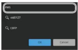
Press the input field in the search window and enter a character string to search for using the keyboard.
Press [OK] to apply the character string to search for. The following items can be searched.
- Content name
- Tags
- Memo
Specifying search criteria
You can specify an AND condition or OR condition to search for multiple character strings.
Note
An AND condition search only matches within each item (content name, tag, memo). You cannot search across multiple items.
| Input example Search criteria | |
| aaa bbb Includes both “aaa” and “bbb” character strings. (Entries separated by a space form an AND condition.) | |
| aaa AND bbb Includes both “aaa” and “bbb” character strings. | |
| aaa OR bbb Includes “aaa” or “bbb” character string. | |
| aaa OR bbb AND ccc | Includes both “bbb” and “ccc” character strings, or includes “aaa”. (AND condition has precedence.) |
| (aaa OR bbb) AND ccc | Includes “aaa” or “bbb” character string and “ccc” character string. (Parentheses have precedence.) |
| “AND” Includes the “AND” character string. (To search for the “AND” or “OR” character string, enclose the word in double quotations.) | |
Search history
The search history is displayed below the input field. You can select a character string to search for from the history.
Selecting content
Select the target content for operation from the list view or thumbnail view.
The selected content is light blue and has focus.
To select multiple content, place a check mark beside the target content to select.
To select all displayed content, place a check mark in the 'select all' checkbox.
Copying Content
1 Open the Home > Content > Browse menu (10201.11). 2 Select the target content to copy.
To select and copy multiple content, place a check mark beside the target content to copy.
To select and copy all displayed content, place a check mark in the 'select all' checkbox.
3 Press the [Copy] button. 4 Check the message, then press [OK].
The [Copy] window appears.
5 Select a copy destination folder.
To create a folder
Press the [New Folder] button to display the [New Folder] window.
Press the input field and enter a folder name (up to 32 characters) using the keyboard, then press [OK].
A new folder is created within the selected folder.
Note
A folder cannot be created when a folder at the 5th level of the hierarchy is selected.
6 Press [OK].
The content is copied to the selected folder.
If content with the same name exists in a folder, a copy count (underscore and copy number) is added to the end of the content name.
Note
Tags and memos added to content are also copied.
Moving Content
Notes
- Locked content cannot be moved.
- Loaded content cannot be moved.
1 Open the Home > Content > Browse menu (10201.11). 2 Select the target content to move.
To select and move multiple content, place a check mark beside the target content to move. To select and move all displayed content, place a check mark in the 'select all' checkbox.
3 Press the [Move] button.
4 Check the message, then press [OK].
The [Move] window appears.
5 Select a destination folder.
To create a folder
Press the [New Folder] button to display the [New Folder] window. Press the input field and enter a folder name (up to 32 characters) using the keyboard, then press [OK]. A new folder is created within the selected folder.
Note
A folder cannot be created when a folder at the 5th level of the hierarchy is selected.
6 Press [OK].
The content is moved to the selected folder. If content with the same name exists in a folder, a copy count (underscore and copy number) is added to the end of the content name.
Deleting Content
Notes
- Locked content cannot be deleted.
- Loaded content cannot be deleted.
1 Open the Home > Content > Browse menu (10201.11).
2 Select the target content to delete.
To select and delete multiple content, place a check mark beside the target content to delete. To select and delete all displayed content, place a check mark in the 'select all' checkbox.
3 Press the [Delete] button.
4 Check the message, then press [OK].
Locking Content
1 Open the Home > Content > Browse menu (10201.11). 2 Select the target content to lock.
To select and lock multiple content, place a check mark beside the target content to lock. To select and lock all displayed content, place a check mark in the 'select all' checkbox.
3 Press the [Lock] button.
Note
If locked content is selected as the target for operation, the locked status is retained.
To release the lock
Select the target content to unlock and press the [Unlock] button.
Note
If unlocked content is selected as the target for operation, the unlocked status is retained.
Editing Content Properties
Notes
- The properties of locked content cannot be edited.
- The properties of loaded content cannot be edited.
1. Open the Home > Content > Browse menu (10201.11). 2. Select the target content to edit.
To select and edit multiple content, place a check mark beside the target content to edit. To select and edit all displayed content, place a check mark in the 'select all' checkbox.
3. Press the [Edit Properties] button.
The [Edit Properties] window appears.
4. Press the [Name] button and enter a content name (up to 64 characters) using the keyboard.
Note
When multiple content is selected, the content names cannot be edited.
5 Select tags to add to content in [Tags].
Place a check mark for each tag to add.
Note
When multiple content is selected, clearing a check mark for a tag removes the tag from all content. Placing a check mark for a tag adds the tag to all content.
To create a tag
Press the [New Tag] button to display the [New Tag] window.
Press the input field and enter a tag name (up to 24 characters) using the keyboard, then press [OK].
6 Press the [Memo] button and enter a memo (up to 255 characters) using the keyboard.
Note
When multiple content is selected, the memo of all content will have the same description.
7 Press [OK].
Combining Content
Combining images
You can combine video and video content resources or still image and still image content resources.
The combined content is saved as new combined content.
The original content is not deleted.
Notes
- Video content with different durations cannot be combined.
- Content with different image attributes, such as resolution and frame rate, cannot be combined.
1 Open the Home > Content > Combine/Separate > Combine Video menu (10201.21).
Selection buttons for content 1 and content 2 are shown on the left.
A list of content is shown on the right.
For details about the list display, see “Displaying Content” (page 368).
Note
Combined content and audio content are not displayed.
2 Press the [Video 1] button on the left.
3 Select content 1 from the list displayed on the right. The thumbnail and information for the selected content is displayed on the [Video 1] button.
4 Press the [Video 2] button on the left.
5 Select content 2 from the list displayed on the right. The thumbnail and information for the selected content is displayed on the [Video 2] button.
6 Press the [Combine Now] button.
To release the content selection, press the [Clear] button.
7 Check the message, then press [OK].
Content 1 and content 2 are combined, and the combined content is saved in the content 1 folder.
Name and properties of combined content
The name and properties of combined content are set according to the following rules.
- The content name is the name of content 1 with “_CMB” appended to the end. If the name exceeds 64 characters, some characters at the end of the content 1 name will be deleted.
- If content with the same name exists, a copy count (underscore and copy number) is added to the end.
- The tag properties of content 1 and content 2 are all added.
- The memo property of content 1 is added.
Linking an image and audio
You can link audio content to video content or video combined content.
The linked content is saved as new content. The original content is not deleted.
1 Open the Home > Content > Combine/Separate > Link Audio menu (10201.22). Selection buttons for video content and audio content are shown on the left. A list of content is shown on the right. For details about the list display, see “Displaying Content” (page 368).
Note
Still image content is not displayed.
2 Press the [Video] button on the left. 3 Select video content from the list displayed on the right. The thumbnail and information for the selected content is displayed on the [Video] button.
4 Press the [Audio] button on the left.
5 Select audio content from the list displayed on the right.
The thumbnail (audio type icon) and information for the selected content is displayed on the [Audio] button.
6 Press the [Link Now] button.
To release the content selection
Press the [Clear] button.
7 Check the message, then press [OK]. The audio content is linked to the video content, and the linked content is saved in the video content folder.
Name and properties of linked content
The name and properties of linked content are set according to the following rules.
- The content name is the name of the video content with “_LNK” appended to the end. If the name exceeds 64 characters, some characters at the end of the video content name will be deleted.
- If content with the same name exists, a copy count (underscore and copy number) is added to the end.
- The tag properties of the video content and audio content are all added.
- The memo property of the video content is added.
- The duration is the same as the video content.
Separating combined/linked content
Separated content is saved as new content. The original content is not deleted.
1 Open the Home > Content > Combine/Separate > Separate menu (10201.23). A list of content is shown on the right. For details about the list display, see “Displaying Content” (page 368).
Note
Only content that can be separated is displayed.
2 Select content from the list displayed on the right. The thumbnail and information for the selected content is displayed on the left.
3 Press the [Separate Now] button.
4 Check the message, then press [OK].
The content is separated and saved in the same folder.
Name and properties of separated content
The name and properties of separated content are set according to the following rules.
- For combined content, the content name is the original name with “_V1” (content 1) and “_V2” (content 2) appended to the end. For linked content, the content name is the original name with “_A” (audio content), “_V1” (video content/video combined content 1), and “_V2” (video combined content 2) appended to the end. If the name exceeds 64 characters, some characters at the end of the combined/linked content name will be deleted.
- If content with the same name exists, a copy count (underscore and copy number) is added to the end.
- The tag properties of the combined/linked content are added.
- The memo property of the combined/linked content is added.
Importing/Exporting Content
Importing Content
You can import files from a computer and save them in content storage as content.
Creating an import list
1 Open the Home > Content > Import/Export > Import from Files menu (10201.31).
An import list and the properties to add to imported content are displayed.
2 Press the [Add] button.
A computer file selection dialog appears.
3 Select a file to import.
The selected file is added to the import list.
Import list
The following information is displayed in the import list.
- Filename
- File modification date and time
- File size
To delete a file from the import list, press the [×] button on the right of the file.
To set the properties to add to imported content
You can set folders for saving content and add tags and a memo to content.
1 Press the [Set Import Properties] button.
The [Set Import Properties] window appears.
2 Select a save destination folder in [Select Destination Folder].
To create a folder
Press the [New Folder] button to display the [New Folder] window.
Press the input field and enter a folder name (up to 32 characters) using the keyboard, then press [OK].
A new folder is created within the selected folder.
Note
A folder cannot be created when a folder at the 5th level of the hierarchy is selected.
3 Select tags to add to content in [Tags].
Place a check mark for each tag to add.
To create a tag
Press the [New Tag] button to display the [New Tag] window.
Press the input field and enter a tag name (up to 24 characters) using the keyboard, then press [OK].
4 Press the input field in [Memo] and enter a memo (up to 255 characters) using the keyboard. 5 Press [OK].
Importing
The files in the import list can be imported.
1 Open the Home > Content > Import/Export > Import from Files menu (10201.31). 2 Press the [Import Now] button. 3 Check the message, then press [OK].
The imported files are saved as content in content storage.
A “☒” icon is displayed on the left for files that failed to import.
Note
The name of imported content is set according to the following rules.
- The content name is the file name with the file name extension removed.
- The content name can be up to 64 characters. The 65th and subsequent characters are deleted.
- If content with the same name exists, a copy count (underscore and copy number) is added to the end.
- Characters that cannot be used are replaced with underscores.
For details, see “Invalid characters for names” (page 87).
Importing a series of still images
When multiple files with names in “character_string + number (or character_string + # + number)” format are imported, the files with the same “character_string” portion and consecutive “number” portions are imported as video content (series of still images). The
"character_string" portion becomes the content name.
Example:
Importing TARGA files
| File name before importing | Content name after importing (series of still images) |
| CAM1#000000.tga | CAM1 |
| CAM1#000001.tga | |
| CAM1#000002.tga | |
| MON101.tga | MON |
| MON102.tga | |
| MON103.tga |
Note
Files in the following file formats can be imported as a series of still images.
• TIFF file - BMP file - TARGA file - PNG file
Importing audio
Audio with a sampling frequency of 32 kHz, 44.1 kHz, or 48 kHz can be imported.
Importing a Content Archive File
Note
Only archive files that have been exported using the Home > Content > Import/Export > Export as Archive menu (10201.33) can be imported.
1 Open the Home > Content > Import/Export > Import from Archive menu (10201.32). 2 Press the [Add] button.
A computer file selection dialog appears.
3 Select an archive file to import.
The file name, modification date and time, and size of the selected archive file are displayed.
To clear an archive file selection
Press the [×] button on the right of the archive file.
4 Press the [Import Now] button. 5 Check the message, then press [OK].
The content is imported.
If content with the same name exists in a folder, a copy count (underscore and copy number) is added to the end of the content name.
Exporting a Content Archive File
Note
It may not be possible to export large archive files, depending on the operating environment.
Reduce the size of the archive file, for example by reducing the number of content resources, and then execute the export again.
1 Open the Home > Content > Import/Export > Export as Archive menu (10201.33).
A list of content is displayed.
For details about the list display, see “Displaying Content” (page 368).
To edit properties
Press the [Edit Properties] button.
For details about editing properties, see “Editing Content Properties” (page 372).
2 Select content to export.
To select and export multiple content, place a check mark beside the target content to export.
To select and export all displayed content, place a check mark in the 'select all' checkbox.
3 Press the [Export Now] button. 4 Check the message, then press [OK].
An archive file for the selected content is exported. The file name extension for an archive file is “.scz”
Editing a Folder
Creating a folder
1 Open the Home > Content > Folder/Tag > Folder menu (10201.41). 2 Select a location (high-level folder) in which to create a folder.
Note
A folder cannot be created when a folder at the 5th level of the hierarchy is selected.
3 Press the [New] button.
The [New Folder] window appears.
4 Press the input field and enter a folder name (up to 32 characters) using the keyboard.
5 Press [OK].
A new folder is created within the selected folder.
Moving a folder
Notes
- Default folders cannot be moved.
- A folder cannot be moved into a lower-level folder within it.
1 Open the Home > Content > Folder/Tag > Folder menu (10201.41).
2 Select the target folder to move.
3 Press the [Move] button.
4 Check the message, then press [OK]. The [Move] window appears.
5 Select a location (high-level folder) in which to move a folder.
To create a folder
Press the [New Folder] button to display the [New Folder] window. Press the input field and enter a folder name (up to 32 characters) using the keyboard, then press [OK]. A new folder is created within the selected folder.
Note
A folder cannot be created when a folder at the 5th level of the hierarchy is selected.
6 Press [OK].
The folder is moved into the selected folder. If a folder with the same name exists, a copy count (underscore and copy number) is added to the end of the folder name.
Note
A folder cannot be moved if it would result in a folder hierarchy exceeding five levels.
Deleting a folder
Only empty folders can be deleted.
Note
Default folders cannot be deleted.
1 Open the Home > Content > Folder/Tag > Folder menu (10201.41). 2 Select the target folder to delete. 3 Press the [Delete] button. 4 Check the message, then press [OK].
Renaming a folder
Note
Default folders cannot be renamed.
1 Open the Home > Content > Folder/Tag > Folder menu (10201.41). 2 Select the target folder to rename. 3 Press the [Rename] button. The [Rename Folder] window appears. 4 Press the input field and enter a folder name (up to 32 characters) using the keyboard. 5 Press [OK].
Editing a Tag
You can create, delete, and rename tags to add to content or packages.
For details about packages, see “Chapter 21 File Management” (page 349).
Creating a tag
1 Open the Home > Content > Folder/Tag > Tag menu (10201.42). 2 Press the [New] button. The [New Tag] window appears. 3 Press the input field and enter a tag name (up to 24 characters) using the keyboard. 4 Press [OK].
Deleting a tag
Notes
- Tags added to locked content/packages cannot be deleted.
- Tags added to loaded content cannot be deleted.
1 Open the Home > Content > Folder/Tag > Tag menu (10201.42).
2 Select the target tag to delete.
To select and delete multiple tags, place a check mark beside the target tags to delete. To select and delete all tags, place a check mark in the 'select all' checkbox.
3 Press the [Delete] button.
4 Check the message, then press [OK].
Note
In addition to the tag definition, tags already added to content/packages are also deleted.
Renaming a tag
1 Open the Home > Content > Folder/Tag > Tag menu (10201.42). 2 Select the target tag to rename.
Note
It is not possible to select and rename multiple tags.
3 Press the [Rename] button. The [Rename Tag] window appears.
4 Press the input field and enter a tag name (up to 24 characters) using the keyboard.
5 Press [OK].
Note
In addition to the tag definition, tags already added to content/packages are also renamed.
System Setup
Chapter
23
Setting Startup
You can select the settings status (startup mode) used at startup.
The following two modes are available.
Resume: Resume mode
Start with the status at the last shutdown.
Custom: Custom mode
Start with settings saved in non-volatile memory.
You can select the following modes separately for setup data and initial status data.
Factory: Start in factory default state.
User: Start in state configured by the user.
Targets of startup mode settings
You can set the startup mode for each of the following targets.
Switcher: Switcher (including DME)
Frame Memory / Clip Player / SL Key Content: Frame memory, clip player, or SL key
Panel: Control panel
For frame memory, clip player, or SL key, the status of the following settings is the target for restoration.
- Content load status
- Frame memory output channel/clip player output channel status (recalled content, combined channels, audio enable/disable).
• Key fill/key source status for SL key (recalled content)
- Loop, playback start point, and playback stop point settings
• [Variable Speed] button and playback speed settings
Notes
- Content that is not saved in content storage cannot be restored.
- When a frame memory output channel, clip player output channel, or key fill/key source for an SL key is locked, the lock is released and the status is restored.
• To restore the content load status, loading is performed automatically in the background when rebooting.
During automatic loading, it is not possible to load/save new content or to freeze/record in frame memory. If the
number of content resources to load is high, loading may take some time.
Saving and Recalling Setup Data
![graph TD A["Storage"] --> B["User setup data"] B --> C["Load Save"] C --> D["RAM"] D --> E["Current setup data\n(In resume mode, used to recall the setup data from the last shutdown)"] E --> F["Power on/reset in custom mode"] F --> G["Initialize"] G --> H["Non-volatile memory"] H --> I["Setup menu […](/content/2026/06/1382172/images/8ce6fde5c71e192a425c02ebe593acac9a8146e31c2ab701ac049e02c319f09e.jpg)
Changing the switcher or control panel setup data saves the updated data in RAM.
You can also save the RAM setup data on a computer for later use.
For details, see "Setup Data File Operations" (page 356).
When the system is turned on/rebooted, the following setup data is recalled depending on the startup mode.
Resume mode: After power off/reset, the RAM setup data is saved and then recalled when booting.
Custom mode: Setup data (user setup data and factory default setup data) saved in non-volatile memory is recalled.
Setting the Startup Mode
You can set the startup mode for each of the switcher, frame memory/clip player/SL key, and control panel.
Note
DMEs are included in the startup mode of the switcher. However, DMEs do not support resume mode. When the switcher is set to resume mode, DMEs start in custom mode.
1 Open the Home > Setup > System > Start Up menu (19101.11). 2 Select the target to set. Select a switcher, frame memory/clip player/SL key, or control panel. 3 Press the [Start Up Mode] button and select a startup mode from the pull-down list.
Resume: Resume mode
Custom: Custom mode
When [Resume] mode is selected, steps 4 and 5 are not required.
Note
You can set the frame memory/clip player/SL key startup mode only when the switcher is set to resume mode.
When the switcher is set to custom mode, frame memory/clip player/SL keys are also set to custom mode (fixed).
4 Press the [Setup] button and select a startup mode from the pull-down list.
User: User setup
Factory: Factory default setup
Note
The setup mode cannot be set for frame memory/clip player/SL keys.
5 Press the [Initial Status] button and select an initial status mode from the pull-down list.
User: User setup
Factory: Factory default setup
Note
When the switcher is set to [Factory] in custom mode, the initial status mode for frame memory/clip player/SL keys is also set to [Factory] (fixed).
Saving user setup
User configured setup data and initial status data are saved in non-volatile memory.
For details about saved data, see "Data Saved by [Setup Define] and [Initial Status Define]" (page 575).
To save setup data
1 Open the Home > Setup > System > Start Up menu (19101.11). 2 In the [Setup Define] group, select the target to save. Switcher: Switcher Panel: Control panel 3 Check the message, then press [OK].
To save initial status data
1 Open the Home > Setup > System > Start Up menu (19101.11). 2 In the [Initial Status Define] group, select the target to save. Switcher/Content: Switcher and frame memory/clip player/SL key Panel: Control panel
3 Check the message, then press [OK].
Applying Initial Status File Settings
You can recall an initial status file to apply the setup status saved in the file, regardless of the startup mode settings.
Notes
- When the [Load and Recall Initial Status] switch is enabled and an initial status file is saved, the setup status at that point in time is saved. For details about initial status files, see “Chapter 21 File Management” (page 349). • Control panel and DME cannot be set.
- You can set frame memory/clip player/SL key only when the switcher setting is enabled. When the switcher setting is disabled, frame memory/clip player/SL keys are set to off (fixed).
1 Open the Home > Setup > System > Start Up menu (19101.11).
2 Select the target to set.
Select switcher or frame memory/clip player/SL key.
3 Enable/disable the function using the [Load and Recall Initial Status] switch.
On: Enabled.
Off: Disabled.
Initializing the System
Initializing the switcher/control panel
You can initialize and reboot the switcher or control panels. The following modes can be selected.
Reset: Reboot according to the startup mode setting.
All Clear: Clear the memory and reboot using the factory default settings.
1 Open the Home > Setup > System > Start Up menu (19101.11).
2 Select the target to set.
Select switcher or control panel.
3 Press the [Initialize] button and select an initialization mode from the pull-down list.
Reset: Reset and reboot.
All Clear: Clear all memory and reboot.
4 Press the [Apply] button in the [Initialize] group.
To return to the previous setting
Press the [Clear] button in the [Initialize] group.
5 Check the message, then press [OK].
Note
The cross-point box does not reboot after initialization.
Initializing the system setup
You can restore the settings of the Home > Setup menu submenu settings to the defaults (setup all clear).
Note
The System Phase setting in the Home > Setup > System > Format/Config > Format menu (19101.22) is not a target for initialization.
1 Open the Home > Setup > System > Start Up menu (19101.11).
2 Press the [Setup All Clear] button.
3 Check the message, then press [OK].
The switcher system reboots.
Setting the System Configuration
Setting Dual Simul Mode
When dual simul mode is enabled, two switchers can be controlled simultaneously from a single control panel.
Notes
- The first switcher is a switcher in the same switcher system as the control panel. For the second switcher, specify a switcher from another switcher system.
- The status of the first switcher is displayed on the control panel and in the menu.
1 Open the Home > Setup > System > Format/Config > Config menu (19101.21). 2 Set the [Dual Simul] button to the on state.
To disable dual simul mode, set the [Dual Simul] button to the off state.
3 Press the [2nd Switcher IP Address] button and enter the IP address of the second switcher using the keyboard. 4 Press the [Apply] button.
To return to the previous setting Press the [Clear] button.
5 Check the message, then press [OK].
The switcher system reboots.
Dual simul mode menus
The following menus can be operated for two switchers at the same time.
• Home > M/E-1 to M/E-5 • Home > M/E-1 Sub to M/E-5 Sub - Home > P/P - Home > P/P Sub - Home > Frame Memory > FMx/FMx > Clip/Still > Recall (FMx/FMx = FM1/FM2 to FM15/FM16) - Home > Frame Memory > FMx/FMx > Clip/Still > Play (FMx/FMx = FM1/FM2 to FM15/FM16) - Home > Clip Player > Clipx/Clipx > Clip > Recall (Clipx/Clipx = Clip1/Clip2 to Clip3/Clip4) - Home > Clip Player > Clipx/Clipx > Clip > Play (Clipx/Clipx = Clip1/Clip2 to Clip3/Clip4) - Home > DME • Home > Other Effects - Home > Utility
- Home > Register > Effect Timeline (switcher banks, users, DME regions only)
- Home > Register > Snapshot (switcher banks, users, DME regions only) • Home > Register > Key Snapshot • Home > Register > Wipe Snapshot • Home > Register > DME Wipe Snapshot
- Home > Setup > System > Input
- Home > Setup > System > Output
- Home > Setup > System > 100G IP Input/Output
- Home > Setup > System > V/K Pair > Physical V/K Pair Assign
- Home > Setup > System > Source > Edit Source Name
- Home > Setup > Xpt Assign > V/K Pair > Logical V/K Pair Assign
- Home > Setup > Xpt Assign > V/K Pair > Edit Logical V/K Pair Name
- Home > Setup > Xpt Assign > V/K Pair > Copy Logical V/K Pair Name
Dual simul mode combinations
The availability of dual simul mode depends on the following combinations of signal formats in the system.
- Home > Setup > Xpt Assign > V/K Pair > Logical V/K Pair Color
- Home > Setup > Xpt Assign > Xpt Delay
- Home > Setup > Switcher > Config > PGM Config
- Home > Setup > Switcher > Config > K-PVW Config
- Home > Setup > Switcher > Config > DSK Bkgd Assign
- Home > Setup > Switcher > Config > DME Config
- Home > Setup > Switcher > Config > User Region Config
- Home > Setup > Switcher > Multi Viewer
- Home > Setup > Switcher > DME Interface
- Home > Setup > Switcher > Custom
- Home > Setup > Switcher > Box Settings
- Home > Setup > Link > Internal Bus Link
- Home > Setup > Link > M/E Link
- Home > Setup > Link > Key Transition Link > Link in Multi M/Es
- Home > Setup > Link > Aux Bus CCR Link
O: Dual simul mode supported
×: Dual simul mode not supported
Δ: Dual simul mode supported with some restrictions
| 1st switcher | 2nd switcher | |||||||||||||
| 2160P 1080P 1080PsF 1080i 720P | ||||||||||||||
| 59.94 | 50 | 29.97 | 25 | 23.98 | 59.94 | 50 | 29.97 | 25 | 23.98 | 59.94 | 50 | 59.94 | ||
| 2160P | 59.94 | ○ | × | △ | × | × | ○ | × | △ | × | × | △ | × | ○ |
| 50 | × | ○ | × | △ | × | × | ○ | × | △ | × | × | △ | × | |
| 29.97 | △ | × | ○ | × | × | △ | × | ○ | × | × | ○ | × | △ | |
| 25 | × | △ | × | ○ | × | × | △ | × | ○ | × | × | ○ | × | |
| 23.98 | × | × | × | × | ○ | × | × | × | × | ○ | × | × | × | |
| 1080P | 59.94 | ○ | × | △ | × | × | ○ | × | △ | × | × | △ | × | ○ |
| 50 | × | ○ | × | △ | × | × | ○ | × | △ | × | × | △ | × | |
| 1080PsF | 29.97 | △ | × | ○ | × | × | △ | × | ○ | × | × | ○ | × | △ |
| 25 | × | △ | × | ○ | × | × | △ | × | ○ | × | × | ○ | × | |
| 23.98 | × | × | × | × | ○ | × | × | × | × | ○ | × | × | × × | |
| 1080i | 59.94 | △ | × | ○ | × | × | △ | × | ○ | × | × | ○ | × | △ |
| 50 | × | △ | × | ○ | × | × | △ | × | ○ | × | × | ○ | × | |
| 720P | 59.94 | ○ | × | △ | × | × | ○ | × | △ | × | × | △ | × | ○ |
Note
When dual simul mode is enabled in a Δ combination, only the following operations can be linked in the Home > Frame Memory > FMx/FMy > Clip/Still > Play menu (FMx/FMy = FM1/FM2 to FM15/FM16) and Home > Clip Player > Clipx/Clipy > Clip > Play menu (Clipx/Clipy = Clip1/Clip2, Clip3/Clip4).
• [Audio On] switch
- [Output Lock] switch
- Move to start of video content
- Move to video playback start point
- Reverse playback (frame memory only)
- Pause playback
- Playback
- Move to video playback stop point
- Move to end of video content • [Variable Speed] button
- [Set Loop Playback] button
Dual simul mode taskbar
The following taskbars can be operated for two switchers at the same time.
The control targets are switcher banks, users, and DME regions only.
• [Effect Timeline Recall/Store] • [Effect Timeline Edit] • [Snapshot]
Setting the Box Configuration
Setting a Switcher Bank/Multi Viewer
In a multiple-box switcher configuration, you can configure a hardware block for use as a switcher bank or as a multi viewer.
The supported hardware blocks are given below.
- When the system signal format is 2160P
M/E box: Block 1, 2
Cross-point box: Block 1
- When the system signal format is 1080P, 1080PsF, 1080i, or 720P
M/E box: Block 1, 2, 3, 4
Cross-point box: Block 1, 2
1 Open the Home > Setup > System > Format/Config > Box Config menu (19101.24). 2 Select a tab (Logical Box ID 1 to Logical Box ID 5) to switch the target to set. 3 In the [Box Config] group, select whether the hardware block is used as a switcher bank or as a multi viewer for each block.
M/E: Enable a switcher bank.
Enhanced MV: Enable an enhanced multi viewer.
Standard MV: Enable a standard multi viewer.
Notes
- An enhanced multi viewer cannot be set to the following.
- When the system signal format is 2160P: M/E box block 2
- When the system signal format is 1080P, 1080PsF, 1080i, or 720P: M/E box block 3, 4
- A standard multi viewer cannot be set to the following.
- When the system signal format is 2160P: M/E box block 1 and cross-point box
- When the system signal format is 1080P, 1080PsF, 1080i, 720P: M/E box block 1, 2 and cross-point box
4 Press the [Apply] button.
To return to the previous setting
Press the [Clear] button.
5 Check the message, then press [OK].
The switcher system reboots.
Setting M/E split
You can split an M/E hardware block (physical M/E block) of the switcher for use as two sub blocks. You can assign a logical M/E to each sub block.
For details about assigning a logical M/E, see “Assigning a logical M/E” (page 410).
Notes
- Enabling M/E split will disable multi program 2 mode.
- When M/E split is enabled, the Out5 to Out8 outputs cannot be used.
- When M/E split is enabled, the keys that can be used in a single physical switcher block can be assigned to the two sub blocks. You can set the number of keys to assign. For details about setting keys, see “Setting sub block full keys” (page 410).
1 Open the Home > Setup > System > Format/Config > Box Config menu (19101.24). 2 Select a tab (Logical Box ID 1 to Logical Box ID 5) to switch the target to set. 3 Select the [M/E Split] switch for the target physical M/E block to the on state. To disable M/E split, set the [M/E Split] switch to the off state.
4 Press the [Apply] button. To return to the previous setting Press the [Clear] button.
5 Check the message, then press [OK]. The switcher system reboots.
Setting a GPU
The DME and SL key functions use a GPU. When the system signal format is 2160P, either the DME function or SL key function can be enabled.
Note
To use the DME function, the MZS-X1610 3D DME License (option) is required. To use the SL key function, the MZS-X1620 SL Key License (option) is required.
1 Open the Home > Setup > System > Format/Config > GPU Config menu (19101.25).
2 In the [GPU Config] group of each box, select a function to enable. DME: Enable DME. SL Key: Enable SL key.
3 Press the [Apply] button.
To return to the previous setting, press the [Clear] button.
4 Check the message, then press [OK]. The switcher system reboots.
Setting DME Channel Enhanced Function Mode
1 Open the Home > Setup > System > Format/Config > GPU Config menu (19101.25). 2 Set enhanced function mode.
To set DME channel 1 In the [DME Channel 1] group, enable/disable enhanced function mode. Enhanced: Enable enhanced function mode. Normal: Disable enhanced function mode.
To set DME channel 2 In the [DME Channel 2] group, enable/disable enhanced function mode. Enhanced: Enable enhanced function mode. Normal: Disable enhanced function mode.
To set DME channel 3 In the [DME Channel 3] group, enable/disable enhanced function mode. Enhanced: Enable enhanced function mode. Normal: Disable enhanced function mode.
3 Press the [Apply] button. To return to the previous setting, press the [Clear] button.
4 Check the message, then press [OK]. The switcher system reboots.
Setting the Signal Format
Setting the Signal Format and Frequency
You can select the system signal format and the field frequency/frame frequency.
The combinations of signal format and frequency that can be set are as follows.
| Signal format Frequency | ||
| 4K 2160P 2SI 59 | .94 | 50 |
| HD 1080P 59.94 | 50 | |
| 1080PsF 29.97 | 2523.98 | |
| 1080i 59.94 | 50 | |
| 720P 59.94 | ||
Notes
- To use 4K formats, the MZS-X1500 4K Upgrade License (option) is required for each target box.
- In a multiple-box switcher configuration, the following restrictions apply.
- The frequency cannot be set to [23.98]. [23.98] can be configured using MLS Manager.
- Switcher and island frequencies of [59.94] and [29.97] can coexist.
When the island frequency is set to [59.94] or [29.97], only a frequency of [59.94] or [29.97] can be set on the switcher. The island frequency is configured using MLS Manager.
- Switcher and island frequencies of [50] and [25] can coexist.
When the island frequency is set to [50] or [25], only a frequency of [50] or [25] can be set on the switcher. The island frequency is configured using MLS Manager.
- When the island frequency is set to [23.98], signal formats [1080P] and [1080i] cannot be configured. The island frequency is configured using MLS Manager.
- The signal format cannot be set to [720P]. [720P] can be configured using MLS Manager. When the signal format of the cross-point box is set to [720P] using MLS Manager, all switchers with multiple-box configuration within an island are set to [720P]. Changing from [720P] to another signal format can also be configured using MLS Manager.
- If the signal formats of a switcher and cross-point box do not match or the switcher and island frequencies do not match, the cross-point box cannot be operated. The cross-point box signal format and island frequency are configured using MLS Manager.
For details, see "About Inaccessible Boxes" (page 19).
1 Open the Home > Setup > System > Format/Config > Format menu (19101.22). 2 Select the [Settings] tab. 3 In the [Signal Format] group, select a signal format.
Note
If a 4K Upgrade License is installed on all boxes in a switcher configuration, [2160P 2SI] can be selected.
4 In the [Frequency] group, select a frequency. 5 Apply the settings.
In a half box or 1M/E box switcher configuration:
- For an M/E-IP or Half-IP type box Press the [Apply] button in the [Signal Format/ Frequency/Ref] group.
- For an M/E-SDI or Half-SDI type box Press the [Apply] button in the [Signal Fmt/Freq/Ref/Sys Delay] group.
In a multiple-box switcher configuration:
Press the [Apply] button in the [Signal Format/Frequency] group.
To return to the previous setting
Press the [Clear] button.
6 Check the message, then press [OK].
The switcher system reboots.
Setting the Reference Signal
You can set the input/output reference signal to HD tri-level sync or black burst.
Note
In a multiple-box switcher configuration, the reference signal lock mode and input/output reference signals cannot be configured. The reference signal is configured using MLS Manager.
Setting the reference signal lock mode
1 Open the Home > Setup > System > Format/Config > Format menu (19101.22). 2 Select the [Settings] tab. 3 In the [Ref Lock Mode] group, select a lock mode.
External: External lock mode Sync to input reference signal.
Internal: Internal lock mode Use switcher internal signal as the reference signal.
4 Press the [Apply] button.
For an M/E-IP or Half-IP type box:
Press the [Apply] button in the [Signal Format/Frequency/Ref] group.
For an M/E-SDI or Half-SDI type box:
Press the [Apply] button in the [Signal Fmt/Freq/Ref/ Sys Delay] group.
To return to the previous setting
Press the [Clear] button.
5 Check the message, then press [OK].
The switcher system reboots.
Setting the input reference signal
Note
Cannot be set when the reference signal is in internal lock mode.
1 Open the Home > Setup > System > Format/Config > Format menu (19101.22). 2 Select the [Settings] tab. 3 In the [Ref Input Format] group, select a reference signal.
Tri Sync: HD tri-level sync
BB: Black burst or sync
Note
When the frequency is [23.98], [Tri Sync] (fixed) is selected.
4 Press the [Apply] button.
For an M/E-IP or Half-IP type box:
Press the [Apply] button in the [Signal Format/Frequency/Ref] group.
For an M/E-SDI or Half-SDI type box:
Press the [Apply] button in the [Signal Fmt/Freq/Ref/ Sys Delay] group.
To return to the previous setting
Press the [Clear] button.
5 Check the message, then press [OK].
The switcher system reboots.
Relationship between signal format and supported input reference signal frequencies
The following table shows the relationship between the signal format and supported input reference signal frequencies.
| Signal format Input reference signal | |||
| Tri Sync BB | |||
| 2160P/59.942SI2160P/29.972SI1080P/59.941080PsF/29.971080i/59.94 | 59.94 Black Burst59.94 | Sync 59.94 | |
| 2160P/50 2SI2160P/25 2SI1080P/501080PsF/251080i/50 | 50 Black Burst50 | Sync 50 | |
| 2160P/23.982SI1080PsF/23.98 | 23.98 -- | ||
| 720P/59.94 59.94 | Black Burst59.94 | Sync 59.94 | |
| 720P/50 50 Black Burst | 50 | Sync 50 | |
Setting the output reference signal
1 Open the Home > Setup > System > Format/Config > Format menu (19101.22). 2 Select the [Settings] tab. 3 In the [Ref Output Format] group, select a reference signal.
Tri Sync: HD tri-level sync
BB: Black burst or sync
Notes
- When the frequency is [23.98], [Tri Sync] (fixed) is selected.
- When the system signal format is 720P and the input reference signal is set to [Tri Sync], the black burst field information generated by the switcher is used when the output reference signal is set to [BB].
4 Press the [Apply] button.
For an M/E-IP or Half-IP type box:
Press the [Apply] button in the [Signal Format/Frequency/Ref] group.
For an M/E-SDI or Half-SDI type box:
Press the [Apply] button in the [Signal Fmt/Freq/Ref/ Sys Delay] group.
To return to the previous setting
Press the [Clear] button.
5 Check the message, then press [OK].
The switcher system reboots.
Setting the Image Switch Timing
1 Open the Home > Setup > System > Format/Config > Format menu (19101.22). 2 Select the [Settings] tab. 3 In the [Switch Timing] group, select the switch timing.
The change in setting is applied immediately.
Any: Not specified
Field1: Field 1
Field2: Field 2
Notes
- When the system signal format is 1080PsF, [Switch Timing] is set to [Field1] (fixed).
- When the system signal format is 2160P and the frequency is 29.97, 25, or 23.98, or when the system signal format is 720P, [Switch Timing] is set to [Any] (fixed).
Setting the Reference Phase
Notes
- In a multiple-box switcher configuration which contains boxes other than an M/E-SDI and XPT-SDI, the reference phase cannot be configured.
- Changing the reference phase of a switcher that contains a cross-point box may affect the operation of other switchers with multiple box configuration within the island.
1 Open the Home > Setup > System > Format/Config > Format menu (19101.22). 2 Press the [System Phase] button and enter a reference phase (microseconds) in the numeric keypad window.
Setting the System Delay Mode
You can set the system delay mode of a switcher with a half box or 1M/E box configuration.
Note
For an M/E-IP or Half-IP type box, the minimum delay mode cannot be configured.
1 Open the Home > Setup > System > Format/Config > Format menu (19101.22). 2 In the [System Delay] group, select a system delay mode.
Normal: Select 1-frame delay mode. Minimum: Select the minimum delay mode.
Note
Any input for which [Frame Synchronizer] is turned on in the Home > Setup > System > Input > Input Adjust menu (19101.31) will operate in 1-frame delay mode.
Displaying Box Information
Boxes are classified as follows, depending on the input/output boards that are installed.
| Box Description | |
| M/E-IP M/E | box with two MKS-X1110 IP Input & Output Boards installed for input/output. |
| M/E-SDI M/E | box with two MKS-X1115 SDI Input & Output Boards installed for input/output. |
| M/E-none M/E | box without any input/output boards installed. |
| M/E-mix M/E | box with MKS-X1110 IP Input & Output Board and MKS-X1115 SDI Input & Output Board installed for input/output (does not operate). |
| Half-IP M/E | box with one MKS-X1110 IP Input & Output Board installed for input/output. |
| Half-SDI M/E | box with one MKS-X1115 SDI Input & Output Board installed for input/output. |
| XPT-IP Cross-point box with MKS-X1110 IP Input & Output Boards installed for input/output. | |
| XPT-SDI Cross-point box with MKS-X1115 SDI Input & Output Boards installed for input/output. | |
| XPT-none Cross-point box without any input/output boards installed. | |
1 Open the Home > Setup > System > Format/Config > Format menu (19101.22).
2 Select the [Information] tab.
The following box information is displayed.
Type-I/O: Displays the box input/output type (M/E-IP, M/E-SDI, M/E-mix, Half-IP, Half-SDI, M/E-none, XPT-IP, XPT-SDI, XPT-none).
LBID: Displays the logical box ID (1 to 5) of the box.
Format/Frequency: Displays the settings of the [Signal Format] group and [Frequency] group of the [Settings] tab for boxes other than a cross-point box. For a cross-point box, it displays the cross-point box signal format and island frequency.
For details about the cross-point box signal format and island frequency, see “Setting the Island Format” (page 497).
Input: Displays the input number of the box. [N/A] is displayed if the box cannot be used or if the box type is M/E-mix, M/E-none, or XPT-none.
Output: Displays the output number of the box. [N/A] is displayed if the box cannot be used or if the box type is M/E-mix, M/E-none, or XPT-none. [---] is displayed if the box type is XPT-IP or XPT-SDI.
Dedicated Output: Displays the dedicated output number of the box. [N/A] is displayed if the box cannot be used or if the box type is M/E-mix, M/E-none, or XPT-none. [-] is displayed for a 1M/E box configuration, and if both the system signal format is 1080P, 1080PsF, 1080i, or 720P and the box type is M/E-SDI.
Note: When the box type is M/E-mix, an error description is displayed. If a box cannot be used, the reason why the box cannot be used is displayed.
Setting the Dynamic Range
Setting the OETF and color space
You can select the OETF (Opto-Electronic Transfer Function) and color space.
The combinations of signal formats and OETF/color space that can be selected are as follows.
| Signal format O | ETF Color space | |
| 2160P SDR BT.709, | BT.2020 | |
| HLG, PQ, S-Log3 (HDR), S-Log3 (Live HDR) | ||
| 1080P, 1080PsF | SDR BT.709 | |
| HLG, PQ, S-Log3 (HDR), S-Log3 (Live HDR) | BT.2020 | |
| 1080i SDR BT.709 | ||
Notes
- When the system signal format is 720P, an HDR converter cannot be used.
- Correct operation may not occur for settings other than the combinations above.
- Changing the OETF/color space settings may momentarily distort the image.
- When TIFF file/BMP file/TARGA file/PNG file content is loaded into frame memory or an SL key, any changes to the color space are not applied to the images. To reflect the change in color space, unload and then reload the content.
1 Open the Home > Setup > System > Format/Config > HDR/SDR Format menu (19101.23).
2 In the [OETF] group, select an OETF.
SDR: SDR (Standard Dynamic Range)
HLG: HLG (Hybrid Log Gamma)
PQ: PQ (Perceptual Quantization)
S-Log3 (HDR): S-Log3
S-Log3 (Live HDR): Display with system gamma added to S-Log3
3 In the [Color] group, select a color space.
BT.709: BT.709 color space
BT.2020: BT.2020 color space
Setting the input signal conversion mode
1 Open the Home > Setup > System > Format/Config > HDR/SDR Format menu (19101.23).
2 In the [Conversion Mode] group, select a conversion mode.
AIR Matching On: Enable the AIR Matching (Artistic Intent Render Matching) function. This performs conversion such that the visual appearance on the output signal display matches that of the input signal display.
AIR Matching Off: Disable the AIR Matching function.
Display Referred: Perform SDR to HDR, HDR to SDR, or HDR to HDR conversion matching the visual appearance of the image on a display.
Setting HDR
You can configure HDR when the OETF is set to [HLG], [PQ], [S-Log3 (HDR)], or [S-Log3 (Live HDR)].
Highlight Creation: Highlight creation function for when converting from SDR to HDR
Highlight creation is a function that makes high-luminance areas brighter according to a knee characteristic during conversion.
Specify the knee point position and slope of the curve.
HDR Contrast: HDR contrast level corresponding to SDR 100% level (display only)
HDR Gain (dB): Gain when converting from SDR to HDR
Note
When the conversion mode is [Display Referred], the highlight creation function cannot be set.
1 Open the Home > Setup > System > Format/Config > HDR/SDR Format menu (19101.23). 2 Enable/disable the highlight creation function using the [Highlight Creation] button. On: Enable the highlight creation function. Off: Disable the highlight creation function. When disabled, proceed to step 5. 3 Press the [Point (Abs.)] button and select a knee point position for the curve from the pull-down list. 4 Press the [Slope (Abs.)] button and select a slope for the curve from the pull-down list. 5 Press the [HDR Gain (dB)] button and enter a gain value in the numeric keypad window.
To set the HDR Look function
You can set the visual appearance of the HDR image on a display.
1 Open the Home > Setup > System > Format/Config > HDR/SDR Format menu (19101.23).
2 Press the [HDR Look] button and select a type of look from the pull-down list.
Live: Vivid images with high contrast and color saturation.
Mild: Generally more mild images than that produced using [Live].
Natural: Images with reduced sensitivity, but which is less affected by noise.
Note
When the OETF is set to [PQ], [S-Log3 (HDR)], or [S-Log3 (Live HDR)], [Natural] cannot be set.
To set the HDR black compression function
You can enable the black compression function and adjust the HDR black level so that it is the same as for SDR.
1 Open the Home > Setup > System > Format/Config > HDR/SDR Format menu (19101.23). 2 Enable/disable the black compression function using the [HDR Black Comp.] button.
On: Enable the black compression function.
Off: Disable the black compression function.
To set the HDR black level
1. Open the Home > Setup > System > Format/Config > HDR/SDR Format menu (19101.23). 2. Press the [Master Black (Abs.)] button in the [Black Level] group and enter a master black value in the numeric keypad window. 3. Press the [HDR Black Offset] button in the [Black Level] group and enter an HDR black offset in the numeric keypad window.
Setting SDR
You can configure SDR when the OETF is set to [SDR].
Knee: Knee function when converting from HDR to SDR The knee is a function that compresses high luminance areas.
Specify the knee point position and slope of the curve.
White Clip: White clip function when converting from HDR to SDR
Specify the level of the video signal.
HDR Contrast: SDR contrast level corresponding to HDR 100% level (display only)
SDR Gain (dB): Gain when converting from HDR to SDR
Gamma (Table): Type of gamma curve Select from standard gamma and hypergamma.
Note
When the conversion mode is [Display Referred], the type of gamma curve cannot be set.
1. Open the Home > Setup > System > Format/Config > HDR/SDR Format menu (19101.23).
2. Enable/disable the knee function using the [Knee] button.
On: Enable the knee function.
Off: Disable the knee function.
When disabled, proceed to step 5.
3 Press the [Point (Abs.)] button and select a knee point position for the curve from the pull-down list.
4 Press the [Slope (Abs.)] button and select a slope for the curve from the pull-down list.
5 Enable/disable the white clip function using the [White Clip] button.
On: Enable the white clip function.
Press the button on the right of the [White Clip] button and enter a video signal level in the numeric keypad window.
Off: Disable the white clip function.
6 Press the [SDR Gain (dB)] button and enter a gain in the numeric keypad window.
7 In the [Gamma (Table)] group, select a type of gamma curve.
Standard: Use standard.
Press the button on the right of the [Standard] button and enter a table number (1 to 7) in the numeric keypad window.
Press the [Step] button and enter a gamma strength (step) in the numeric keypad window.
The effect changes in increments of 0.05.
Press the [Level] button and enter a gamma strength (level) in the numeric keypad window.
Hyper: Use hypergamma.
Press the button on the right of the [Hyper] button and enter a table number (1 to 4) in the numeric keypad window.
Setting the Input Signal
This section describes how to set the switcher input signal.
The number of switcher inputs, number of configurable format converters, and number of configurable color correctors/HDR converters will vary depending on the signal format and the number of boxes.
For details about the number of inputs and the number that can be configured, see “Number of Switcher Resources” (page 548).
For details about input numbers, see “Input/Output Numbers” (page 550).
Setting a Source Name
You can set the source name of an input signal.
1 Open the Home > Setup > System > Input > Input Adjust menu (19101.31).
2 Select the target input to set.
To select and set multiple inputs, place a check mark beside the target inputs to set.
To select and set all inputs, place a check mark in the 'select all' checkbox.
3 Press the [Source Name] button and enter a source name (up to 16 characters) using the keyboard.
Note
When multiple inputs are selected, consecutively numbered source names are set.
For details, see “Name settings when multiple items are selected” (page 87).
Selecting Inputs Configurable with a Color Corrector/HDR Converter
You can set inputs that can be configured with a color corrector/HDR converter.
Note
A color corrector/HDR converter can be configured only for inputs 1 and multiples of 4 + 1 (1, 5, 9, and so on).
1 Open the Home > Setup > System > Input > Input Adjust menu (19101.31).
2 Select the target input to set.
To select and set multiple inputs, place a check mark beside the target inputs to set.
3 Set the [CCR/HDR] switch to the on state.
Setting a Frame Delay
Note
Ancillary data is deleted from signals for inputs configured with a frame delay.
1 Open the Home > Setup > System > Input > Input Adjust menu (19101.31). 2 Select the target input to set.
To select and set multiple inputs, place a check mark beside the target inputs to set.
To select and set all inputs, place a check mark in the 'select all' checkbox.
3 Set the [Frame Delay] switch to the on state.
To disable a frame delay, set the [Frame Delay] switch to the off state.
4 Press the button on the right of the [Frame Delay] switch and enter a delay value in the numeric keypad window.
The delay value that can be set will vary depending on the 100G IP input/SDI input type and the signal format of the input signal.
• 100G IP input: 1 to 4 frames • SDI input at 2160P, 1080P, 720P: 1 to 11 frames - SDI input at 1080PsF or 1080i: 1 to 4 frames
Setting a Frame Synchronizer
When a frame synchronizer is enabled, unsynchronized input signals are synchronized.
Notes
- Configurable only for SDI input.
- Always enabled (display always on) for 100G IP input.
- Ancillary data is deleted from signals for inputs configured with a frame synchronizer set to on.
1 Open the Home > Setup > System > Input > Input Adjust menu (19101.31). 2 Select the target input to set.
To select and set multiple inputs, place a check mark beside the target inputs to set.
To select and set all inputs, place a check mark in the 'select all' checkbox.
3 Set the [Frame Synchronizer] switch to the on state.
To disable a frame synchronizer, set the [Frame Synchronizer] switch to the off state.
Setting a Format Converter
You can use a format converter on odd-numbered inputs.
Notes
A format converter cannot be used in the following cases.
- When the system signal format is 2160P and the frequency is 29.97, 25, or 23.98
- When the system signal format is 1080PsF and the input signal is IP
- When the system signal format is 720P
Setting the conversion format
You can set the signal format of an input signal to convert by the format converter.
Notes
- Field frequency and frame frequency conversion is not supported.
- If a conversion format that is different from the system signal format is configured, the ancillary data will be deleted.
- When receiving IP signals, adjacent ports may be affected if the adjacent input ports are in the following states.
- When a signal is input that is different from the input format converter setting
- When the input format converter setting is changed
- When one input signal is disconnected while the same signal source is being input. The following ports are affected, depending on the signal format of the system.
- 2160P: Affected in units of 2 ports. [1ch-2ch] [3ch-4ch] ... [143ch-144ch]
- 1080P, 1080PsF, 1080i: Affected in units of 4 ports. [1ch-4ch] [5ch-8ch] ... [157ch-160ch]
The signal formats that can be converted are given below.
| System signal format (frequency) | Signal format of input signal |
| 2160P 2SI(59.94, 50) | 1080i1080P2160P 2SI a)2160P 2SI 3G b) c)2160P 2SI 12G b) |
| 1080P(59.94, 50) | 720P1080i1080P |
| 1080PsF(29.97, 25, 23.98) | 1080PsF1080P b) |
| 1080i(59.94, 50) | 720P1080i |
a) Configurable only for 100G IP input. b) Configurable only for SDI input. c) Only the first number input in each group of four odd-numbered inputs (for example, the port numbers for input connectors 1, 3, 5, 7 are 1, 2, 3, 4) can be set. The settings of the inputs in each group are linked and change accordingly.
1 Open the Home > Setup > System > Input > FC Format menu (19101.32).
2 Select the target input to set.
To select and set multiple inputs, place a check mark beside the target inputs to set. To select and set all inputs, place a check mark in the 'select all' checkbox.
3 Press the [FC Format] button and select an input signal format from the pull-down list.
Adjusting the conversion method
The conversion method adjustment items and the target conversion formats are given below.
| Adjustment item Conversion format | |
| Up-converter conversion mode | • 1080i → 2160P |
| I/P converter conversion mode | • 1080i → 1080P |
| • 1080i → 1080i a) | |
a) You can set the conversion mode when the system signal format is 1080i and the input signal format is 1080i.
When the system signal format is 1080PsF, you can also set the conversion mode of the input signal.
1 Open the Home > Setup > System > Input > FC Adjust menu (19101.33).
2 Select the target input to set.
To select and set multiple inputs, place a check mark beside the target inputs to set.
To select and set all inputs, place a check mark in the 'select all' checkbox.
3 Adjust the conversion method.
To set the up-converter conversion mode
Press the [Conversion] button and select a conversion mode from the pull-down list.
Frame: Conversion in frame units
Field: Conversion in field units
Adaptive: Detects motion in the signal, and automatically switches mode between conversion in frame units and field units.
When [Adaptive] is selected, press the [Motion] button and enter a detection sensitivity (1 to 4) in the numeric keypad window.
1: Highest proportion converted from frames (still image priority mode). 2: Higher proportion converted from frames. 3: Higher proportion converted from fields. 4: Highest proportion converted from fields (motion priority mode).
To set the I/P converter conversion mode
Press the [Conversion] button and select a conversion mode from the pull-down list.
Frame: Conversion in frame units
Field: Conversion in field units
Adaptive Y: Detects motion in the luminance signal, and automatically switches mode between conversion in frame units and field units.
Adaptive Y/C: Detects motion in the luminance signal and chrominance signal, and automatically switches mode between conversion in frame units and field units.
When [Adaptive Y] or [Adaptive Y/C] is selected, press the [Motion] button and enter a detection sensitivity (1 to 4) in the numeric keypad window.
1: Highest proportion converted from frames (still image priority mode). 2: Higher proportion converted from frames. 3: Higher proportion converted from fields. 4: Highest proportion converted from fields (motion priority mode).
To set the conversion mode when the system signal format is 1080PsF
When the system signal format is 1080PsF, press the [Conversion] button and select a conversion mode from the pull-down list.
Frame: Conversion in frame units
Field: Conversion in field units
Note
Set to [Field] for normal operation. Set to [Frame] if using CG or other still image content as the input signal and you are concerned about the appearance of the image quality due to internal processing.
To return the conversion method settings to the defaults
Press the [Default] button.
Setting a Color Corrector
You can set the following color corrector functions for inputs that have color corrector/HDR converter enabled.
• Primary color correction - RGB clip
For details about inputs that can be configured with a color corrector/HDR converter, see “Selecting Inputs Configurable with a Color Corrector/HDR Converter” (page 390).
1 Open the Home > Setup > System > Input > Input CCR menu (19101.34). 2 Select the target input to set. 3 Set the [CCR] button in the [CCR] group to the on state.
To disable a color corrector, set the [CCR] button to the off state.
To return color corrector settings to the defaults
Press the [Unity] button in the [CCR] group, check the message, then press [OK].
All color corrector function settings are returned to the defaults.
To set primary color correction
Set the [Primary CCR] button in the [Primary CCR] group to the on state and set the parameters.
For details about setting primary color correction, see "Setting primary color correction" (page 251).
To set the RGB clip function
Set the [RGB Clip] button in the [RGB Clip] group to the on state and set the parameters.
For details about setting the RGB clip function, see "Setting RGB clip" (page 252).
Setting an HDR Converter
You can set the input signal OETF, color space, and HDR converter for inputs that have color corrector/HDR converter enabled.
For details about each HDR conversion item, see "Setting HDR" (page 389).
For details about inputs that can be configured with a color corrector/HDR converter, see "Selecting Inputs Configurable with a Color Corrector/HDR Converter" (page 390).
Notes
- To use the HDR converter function, the MZS-X1750 HDR Converter License (option) is required for each target box.
- When the system signal format is 720P, an HDR converter cannot be used.
1 Open the Home > Setup > System > Input > HDR Converter menu (19101.35).
The system OETF, color space, and HDR settings are displayed in [System Settings].
2 Select the target input to set.
To select and set multiple inputs, place a check mark beside the target inputs to set.
To select and set all inputs, place a check mark in the 'select all' checkbox.
3 Press the [Input Signal OETF] button and select an OETF from the pull-down list.
Select [SDR], [HLG], [PQ], [S-Log3 (HDR)], or [S-Log3 (Live HDR)].
4 Press the [Color] button and select a color space from the pull-down list.
Select [BT.709] or [BT.2020].
5 Enable/disable the system settings using the [Follow System Settings] switch.
On: Enable system settings. Apply the system settings to the input signal.
Off: Disable system settings. Apply different settings than the system settings to the input signal.
If the system settings are disabled, press the [Adjust Details] button and configure the HDR conversion settings in the [HDR Converter] window.
Note
When multiple inputs are selected, the [Follow System Settings] switch settings do not change in unison.
[HDR Converter] window > [Config] tab
Sets the HDR conversion mode.
1 In the [Conversion Mode] group, select a conversion mode.
Select [AIR Matching On], [AIR Matching Off], or [Display Referred].
2 Press the [HDR Look] button and select a type of look from the pull-down list.
Select [Live], [Mild], or [Natural].
Notes
- When the input signal OETF is set to [PQ], [S-Log3 (HDR)], or [S-Log3 (Live HDR)], [Natural] cannot be selected.
- This cannot be set when the input signal OETF is set to [SDR].
- This cannot be set when the [Look Conversion] button is set to the on state on the [Additional Paint] tab.
3 Enable/disable the black compression function using the [HDR Black Comp.] button.
Note
This cannot be set when the [Look Conversion] button is set to the on state on the [Additional Paint] tab.
4 In the [Black Level] group, set the black level.
For a Sony system camera input signal
Press the [Sony System Camera] button. Press the [Master Black (Abs.)] button and enter a master black value in the numeric keypad window. Press the [HDR Black Offset] button and enter an HDR black offset in the numeric keypad window.
For a non-Sony system camera input signal
Press the [Others] button. Press the [Master Black (HDR)] button and enter an HDR black level in the numeric keypad window. Press the [Master Black (SDR)] button and enter an SDR black level in the numeric keypad window.
Notes
- When the system OETF and input signal OETF are set to [SDR], [Black Level (HDR)] cannot be set.
- When the system OETF and input signal OETF are set to [HLG], [PQ], [S-Log3 (HDR)], or [S-Log3 (Live HDR)], [Black Level (SDR)] cannot be set.
[HDR Converter] window > [Conversion] tab
Sets the mode for conversion from HDR to HDR, SDR to HDR, or HDR to SDR.
Note
This cannot be set when the system OETF and input signal OETF are set to [SDR].
When converting from HDR to HDR
Enable/disable the black clip function using the [HDR Black Clip] button.
On: Enable the black clip function.
Off: Disable the black clip function.
Note
This cannot be set when the system OETF is set to [S-Log3 (HDR)] or [S-Log3 (Live HDR)].
When converting from SDR to HDR
1 Enable/disable the highlight creation function using the [Highlight Creation] button.
On: Enable the highlight creation function. Press the [Point (Abs.)] button and select a knee point position for the curve from the pull-down list. Press the [Slope (Abs.)] button and select a slope for the curve from the pull-down list.
Off: Disable the highlight creation function.
Note
When the conversion mode is set to [Display Referred] in the [Conversion Mode] group, this cannot be set.
2 Press the [HDR Gain (dB)] button and enter a gain for converting in the numeric keypad window.
The HDR percentage level that results after conversion of SDR 100% level varies depending on the gain setting and is displayed in [HDR Contrast].
3 In the [De-Gamma] group, set the type of gamma curve for the inverse conversion.
Standard: Use standard.
Press the button on the right of the [Standard] button and enter a table number (1 to 7) in the numeric keypad window.
Hyper: Use hypergamma.
Press the button on the right of the [Hyper] button and enter a table number (1 to 4) in the numeric keypad window.
Note
This cannot be set when the input signal conversion mode is set to [Display Referred].
4 Enable/disable the black clip function using the [HDR Black Clip] button.
On: Enable the black clip function.
Off: Disable the black clip function.
Note
This cannot be set when the system OETF is set to [S-Log3 (HDR)] or [S-Log3 (Live HDR)].
When converting from HDR to SDR
1 Enable/disable the knee function using the [Knee] button.
On: Enable the knee function.
Press the [Point (Abs.)] button and select a knee point position for the curve from the pull-down list.
Press the [Slope (Abs.)] button and select a slope for the curve from the pull-down list.
Off: Disable the knee function.
2 Enable/disable the white clip function using the [White Clip] button.
On: Enable the white clip function.
Press the button on the right of the [White Clip] button and enter a video signal level in the numeric keypad window.
Off: Disable the white clip function.
3 Press the [SDR Gain (dB)] button and enter a gain for converting in the numeric keypad window.
The SDR percentage level that results after conversion of HDR 100% level varies depending on the gain setting and is displayed in [HDR Contrast].
4 In the [Gamma (Table)] group, select a type of gamma curve.
Standard: Use standard.
Press the button on the right of the [Standard] button and enter a table number (1 to 7) in the
numeric keypad window.
Press the [Step] button and enter a gamma strength (step) in the numeric keypad window.
The effect changes in increments of 0.05.
Press the [Level] button and enter a gamma strength (level) in the numeric keypad window.
Hyper: Use hypergamma.
Press the button on the right of the [Hyper] button and enter a table number (1 to 4) in the numeric keypad window.
[HDR Converter] window > [Additional Paint] tab
Adjusts the image quality of the input signal.
1 Set the [Additional Paint] button to the on state.
When not adjusting the image quality, set the [Additional Paint] button to the off state.
2 Set the white balance function using the [White Balance] button.
On: Adjust the white balance.
Press the [R] button and enter an R gain value in the numeric keypad window.
Press the [B] button and enter a B gain value in the numeric keypad window.
Off: Do not adjust the white balance.
3 Set the master white gain function using the [Master White Gain (dB)] button.
On: Adjust the master white gain.
Press the right button and enter a master white gain value in the numeric keypad window.
Off: Do not adjust the master white gain.
4 Set the saturation using the [Saturation] button.
On: Adjust the saturation.
Press the right button and enter a saturation in the numeric keypad window.
Off: Do not adjust the saturation.
5 Set the look conversion function using the [Look Conversion] button.
On: Enable look and black compression.
Press the [Input Look] button and select an input look (Live, Mild, Natural) from the pull-down list.
Enable/disable the input black compression function using the [Input Black Comp.] button. Press the [Output Look] button and select an output look (Live, Mild, Natural) from the pull-down list.
Enable/disable the output black compression function using the [Output Black Comp.] button. Off: Disable look and black compression.
Note
This cannot be set when the input signal conversion mode is set to [AIR Matching Off] or [Display Referred].
Returning [HDR Converter] window settings to the initial settings
Press the [Default Recall] button in the [HDR Converter] window. The settings on all tabs in the [HDR Converter] window are returned to the following values. [Config] tab: System settings values [Conversion] tab: System settings values [Additional Paint] tab: Default values
Setting the Output Signal
This section describes how to set the switcher output signal.
In a multiple-box switcher configuration, there are two types of switcher output signals.
Dedicated output:
Outputs the internal signal of the target box. The various settings are configured on the [Dedicated Out] tab in the Home > Setup > System > Output menus.
Output:
Outputs an Aux, Edit Preview, or Preset signal. These can also output the internal signal of another box.
To output the internal signal of another box, the internal signal of the target box must be sent to the cross-point box.
For details about sending to the cross-point box, see "Setting Re-Entry Signals" (page 424).
The various settings are configured on the [Output] tab in the Home > Setup > System > Output menus. In a 1M/E box switcher configuration, only the following signals are output.
Output: Outputs a box internal signal, Aux, Edit Preview, or Preset signal.
The various settings are configured on the [Output] tab in the Home > Setup > System > Output menus. The number of switcher outputs, number of configurable format converters, and number of configurable color correctors/HDR converters will vary depending on the signal format and the number of boxes.
For details about the number of outputs and the number that can be configured, see “Number of Switcher Resources” (page 548).
For details about output numbers, see “Input/Output Numbers” (page 550).
Assigning an Output Signal
You can assign an output signal.
1 Open the Home > Setup > System > Output > Output Assign menu (19101.41). 2 Select a tab to switch the target to set.
[Output] tab: Assigns output signals to outputs.
[Dedicated Out] tab: Assigns output signals to dedicated outputs.
3 Select the target output to set.
To select and set multiple outputs, place a check mark beside the target outputs to set.
To select and set all outputs, place a check mark in the 'select all' checkbox.
4 Press the [Edit] button.
The [Output Assign] window appears.
5 Set the button for the signal to assign to the on state.
Select a tab to change the type of signal to display.
- When the [Output] tab is selected
[PP/ME Out] tab: Switcher bank outputs
[CB/DME/FM/Clip/MV] tab: Color background/DME/frame memory/clip player/multi viewer outputs
[Aux] tab: AUX outputs
[Aux Mix] tab: AUX mix outputs
- When the [Dedicated Out] tab is selected
[PP/ME Out] tab: Switcher bank outputs
[CB/DME/FM/Clip/MV] tab: Color background/DME/frame memory/clip player/multi viewer outputs
Note
An AUX output signal cannot be assigned to more than one output. When multiple outputs are selected, the [Aux] and [Aux Mix] tabs are not displayed.
6 Press [OK].
Assignable signals
[PP/ME Out] tab:
P/P Out1 to P/P Out8 1) 2)
M/E-x Out1 to M/E-x Out8 ("x" is 1 to 5) 1) 2)
[CB/DME/FM/Clip/MV] tab:
Undefined (when signal is not assigned)
Color Bkgd2
DME Monitor Video 3)
DME Monitor Key 3)
Frame Memory1 to Frame Memory16
Clip Player1 to Clip Player4
Multi Viewer1 to Multi Viewer4 2) 4)
[Aux] tab:
Aux1 to Aux48
Edit Preview
Preset
[Aux Mix] tab:
Aux1/2 to Aux47/48
1) The assigned signal name is displayed in the Home > Setup > Switcher > Config > M/E Config menu (19103.12).
2) When an output signal is assigned to a Dedicated Output in the following slots in a multiple-box configuration, only the signals assigned to a bank can be output.
- When the system signal format is 2160P:
Slot 1: M/E or multi viewer assigned to bank 1
Slot 4: M/E or multi viewer assigned to bank 2
- When the system signal format is 1080P, 1080PsF, 1080i, or 720P: Slot 1: M/E or multi viewer assigned to block 1 or block 2 Slot 4: M/E or multi viewer assigned to block 3 or block 4
3) When an output signal is assigned to a Dedicated Output in the following slots in a multiple-box configuration, or when an output signal is assigned to the following slots in a 1M/E box configuration, only the DME channel signals used on an M/E assigned to a bank can be output.
- When the system signal format is 2160P:
Slot 1: DME channel used on an M/E assigned to bank 1 Slot 4: DME channel used on an M/E assigned to bank 2
- When the system signal format is 1080P, 1080PsF, 1080i, or 720P: Slot 1: DME channel used on an M/E assigned to bank 1 or bank 2 Slot 4: DME channel used on an M/E assigned to bank 3 or bank 4
4) When an output signal is assigned to an Output in the following slots in a 1M/E box configuration, only the following multi viewers can be output.
- When the system signal format is 2160P: Slot 1: Multi viewer 1 Slot 4: Multi viewer 2
- When the system signal format is 1080P, 1080PsF, 1080i, or 720P: Slot 1: Multi viewer 1 and multi viewer 2 Slot 4: Multi viewer 3 and multi viewer 4
For details about switcher bank assignment, see “Setting a Switcher Bank” (page 410).
Selecting Outputs Configurable with a Color Corrector/HDR Converter
You can set outputs that can be configured with a color corrector/HDR converter.
Notes
- A color corrector/HDR converter can be configured only for outputs 1 and multiples of 4 + 1 (1, 5, 9, and so on).
- When the system signal format is 720P, dedicated outputs cannot be configured.
1 Open the Home > Setup > System > Output > Output Assign menu (19101.41).
2 Select the target output to set.
To select and set multiple outputs, place a check mark beside the target outputs to set.
3 Set the [CCR/HDR] switch to the on state.
Setting Through Mode
When through mode is enabled, the input signal ancillary data is passed to the output without change.
You can enable through mode for the following output signals.
- Aux1 to Aux48
- Edit Preview • Frame Memory1 to Frame Memory16
- Clip Player1 to Clip Player4
- M/E-x PGM1 to M/E-x PGM4 (x = 1 to 5)
- M/E-x CLEAN, M/E-x SUB CLEAN (x = 1 to 5)
- M/E-x K-PVW1 to M/E-x K-PVW2 (x = 1 to 5) • P/P PGM1 to P/P PGM4 • P/P CLEAN, P/P SUB CLEAN • P/P K-PVW1 to P/P K-PVW2
Notes
- For “Frame Memory1” to “Frame Memory16” and “Clip Player1” to “Clip Player4,” the ancillary data contains audio data only. Metadata is not included.
- Through mode cannot be set if the conversion format of the output signal format converter is different from the system signal format.
- In through mode when MKS-X1110 IP Input & Output Boards are installed, only outputs 1 and multiples of 4 + 1 (1, 5, 9, and so on) can be configured.
- Ancillary data is deleted when a frame synchronizer or frame delay is configured for the input signal.
- When MKS-X1110 IP Input & Output Boards are installed, ancillary data is deleted from the signals on inputs 1 and multiples of 4 + 1 (1, 5, 9, and so on).
- In a 1M/E box switcher configuration, ancillary data is deleted in the following cases.
- When signals on ports on slot 1 are output from ports on slot 4
- When signals on ports on slot 4 are output from ports on slot 1. For details about the relationship between slots and input/output port numbers, see “Input/Output Numbers” (page 550).
1 Open the Home > Setup > System > Output > Output Assign menu (19101.41). 2 Select the target output to set.
To select and set multiple outputs, place a check mark beside the target outputs to set.
To select and set all outputs, place a check mark in the 'select all' checkbox.
3 Enable/disable through mode using the [Through Mode] switch.
On: Enable through mode.
Off: Disable through mode.
Setting the Video Clip Function
1 Open the Home > Setup > System > Output > Video Adjust menu (19101.42).
2 Select a tab to switch the target to set.
[Output] tab: Output video clip settings [Dedicated Out] tab: Dedicated output video clip settings
3 Select the target output to set and set the following parameters.
| No. | Parameter Adjustment | |
| 1 | White Clip Luminance | signal white clip value |
| 2 | Dark Clip Luminance | signal dark clip value |
| 3 | Chroma Clip Chrominance | signal clip value |
To return the settings to the defaults
Press the [Reset] button.
Setting the Safe Title Area
1 Open the Home > Setup > System > Output > Safe Title menu (19101.43). 2 Select a tab to switch the target to set.
[Output] tab: Output safe title settings [Dedicated Out] tab: Dedicated output safe title settings
3 Select the target output to set. 4 Set the safe title area display method.
To display box 1
Set the [Box1] button to the on state.
Set the following parameter.
| No. | Parameter Adjustment | |
| 1 Size | Size |
In the [Box1 Adjust] group, select an aspect ratio (16:9, 14:9, 4:3).
To display box 2
Set the [Box2] button to the on state.
Set the following parameters.
| No. | Parameter Adjustment |
| 1 Size | Size |
| 2 Luminance | Luminance |
In the [Box2 Adjust] group, select an aspect ratio (16:9, 14:9, 4:3).
To display a cross
Set the [Cross] button to the on state.
To display a grid
Set the [Grid] button to the on state.
In the [Grid Adjust] group, select an aspect ratio (16:9, 4:3).
In the [Grid Size] group, select a size (80.00%, 85.00%, 90.00%, 100.00%).
To return the settings to the defaults
Press the [Reset] button.
Setting a Format Converter
You can convert the signal format of an output signal.
You can use a format converter on odd-numbered outputs.
Note
A format converter cannot be used in the following cases.
- When the system signal format is 2160P and the frequency is 29.97, 25, or 23.98
- When the system signal format is 1080PsF or 720P
Setting the conversion format
You can set the signal format of an output signal to convert by the format converter.
Notes
- Field frequency and frame frequency conversion is not supported.
- If a conversion format that is different from the system signal format is configured, the ancillary data will be deleted.
The signal formats that can be converted are given below.
| System signal format (frequency) | Signal format of output signal |
| 2160P 2SI(59.94, 50) | 1080i1080P2160P 2SI a)2160P 2SI 3G b) c)2160P 2SI 12G b) |
| 1080P(59.94, 50) | 720P1080i1080P |
| 1080i(59.94, 50) | 720P1080i |
a) Configurable only for 100G IP output. b) Configurable only for SDI output. c) Only the first number output in each group of four outputs can be set. The settings of the outputs in each group are linked and change accordingly.
1 Open the Home > Setup > System > Output > FC Format menu (19101.44).
2 Select a tab to switch the target to set.
[Output] tab: Output converter format settings [Dedicated Out] tab: Dedicated output converter format settings
3 Select the target output to set.
To select and set multiple outputs, place a check mark beside the target outputs to set.
To select and set all outputs, place a check mark in the 'select all' checkbox.
4 Press the [FC Format] button and select an output signal format from the pull-down list.
Setting an HDR Converter
You can set the output signal OETF, color space, and HDR converter for outputs that have color corrector/HDR converter enabled.
For details about each HDR conversion item, see "Setting HDR" (page 389).
For details about outputs that can be configured with a color corrector/HDR converter, see "Selecting Outputs Configurable with a Color Corrector/HDR Converter" (page 397).
Notes
- To use the HDR converter function, the MZS-X1750 HDR Converter License (option) is required for each target box.
- When the system signal format is 720P, an HDR converter cannot be used.
1 Open the Home > Setup > System > Output > HDR Converter menu (19101.46).
The system OETF, color space, and HDR settings are displayed in [System Settings].
2 Select a tab to switch the target to set.
[Output] tab: Output HDR converter settings [Dedicated Out] tab: Dedicated output HDR converter settings
3 Select the target output to set.
To select and set multiple outputs, place a check mark beside the target outputs to set.
To select and set all outputs, place a check mark in the 'select all' checkbox.
4 Press the [Output Signal OETF] button and select an OETF from the pull-down list.
Select [SDR], [HLG], [PQ], [S-Log3 (HDR)], or [S-Log3 (Live HDR)].
5 Press the [Color] button and select a color space from the pull-down list.
Select [BT.709] or [BT.2020].
6 Enable/disable the system settings using the [Follow System Settings] switch.
On: Enable system settings. Apply the system settings to the output signal.
Off: Disable system settings. Apply different settings than the system settings to the output signal. If the system settings are disabled, press the [Adjust Details] button and configure the HDR conversion settings in the [HDR Converter] window.
Note
When multiple outputs are selected, the [Follow System Settings] switch settings do not change in unison.
[HDR Converter] window > [Config] tab
Configure the output signal in the same way as for an input signal.
For details, see “[HDR Converter] window > [Config] tab” (page 394).
Note
Only the [Master Black (Abs.)] button and [HDR Black Offset] button settings are available in the [Black Level] group for an output signal.
[HDR Converter] window > [Conversion] tab
Configure the output signal in the same way as for an input signal.
For details, see “[HDR Converter] window > [Conversion] tab” (page 394).
Note
This cannot be set when the system OETF and output signal OETF are set to [SDR].
[HDR Converter] window > [Additional Paint] tab
Configure the output signal in the same way as for an input signal.
For details, see “[HDR Converter] window > [Additional Paint] tab” (page 395).
Notes
- When the look conversion function is set using the [Look Conversion] button and the system OETF is set to [PQ], [S-Log3 (HDR)], or [S-Log3 (Live HDR)], [Natural] cannot be selected for [Input Look]. When the output signal OETF is set to [PQ], [S-Log3 (HDR)], or [S-Log3 (Live HDR)], [Natural] cannot be selected for [Output Look].
- When the look conversion function is set using the [Look Conversion] button and the system OETF is set to [SDR], [Input Look] cannot be set. When the output signal OETF is set to [SDR], [Output Look] cannot be set.
Returning [HDR Converter] window settings to the initial settings
Press the [Default Recall] button in the [HDR Converter] window.
The settings on all tabs in the [HDR Converter] window are returned to the following values.
[Config] tab: System settings values
[Conversion] tab: System settings values
[Additional Paint] tab: Default values
Setting 100G IP Input/Output Signals
Note
If no MKS-X1110 IP Input & Output Boards are installed in an M/E box, half box, or cross-point box configured in a switcher, the menu will not be displayed.
Setting an ST 2110 Stream
You can set whether to send redundant ST 2110 streams (input/output).
1 Open the Home > Setup > System > 100G IP Input/Output > Config menu (19101.52). 2 Enable/disable using the [Hitless Failover] button.
On: Send redundant ST 2110 streams (input/output).
Off: Do not send redundant ST 2110 streams (input/output).
3 Press the [Apply] button.
To return to the previous setting Press the [Clear] button.
4 Check the message, then press [OK].
Setting Multicasting
You can configure multicasting for each output of boxes configured in a switcher.
For details about output numbers, see "Input/Output Numbers" (page 550).
Notes
Cannot be configured in the following cases.
- When [NDCP(LSM)] is configured in the [Protocol] group in the Home > Setup > 100G IP I/F > Controller > Protocol menu (19108.21)
- When [NMOS] is configured in the Setup > 100G IP I/F > Controller > Protocol menu (19108.21) and [Stop] is configured in the [Device Connection Mgmt (IS-05) Start Up Mode] group in the Home > Setup > 100G IP I/F > Controller > NMOS menu (19108.22)
1 Open the Home > Setup > System > 100G IP Input/Output > Output Multicast menu (19101.54).
2 Select a tab to switch the target to set.
[Video] tab: Change video settings
[Audio] tab: Change audio settings
[Meta] tab: Change metastream settings
Note
Audio and metastreams can be configured only for ports 1 and multiples of 4 + 1 (1, 5, 9, and so on).
3 Select the target button to set.
To select and set multiple buttons, place a check mark beside the target buttons to set.
To select and set all buttons, place a check mark in the 'select all' checkbox.
You can also press the [Select Number(s)] button and enter a number in the numeric keypad window.
The video stream (ST 2110) transmission status and output name are displayed in [Strm Sts./Name].
To sort the multicast list display
You can press a display item title to sort the display. Pressing a title switches between ascending and descending order each time you press the title, and [▲] (ascending) or [▼] (descending) is displayed on the right side of the title.
Box Slot/Port: Sort by slot number/port number
Strm Sts./Name: Sort by video stream (ST 2110) transmission status and output name
4 Enable/disable the video/audio/metastreams (ST 2110) using the [Stream Stop/Start] switch.
On: Output video stream (ST 2110).
Off: Do not output video stream (ST 2110).
5 Set the multicast primary address and port number.
[Primary Address] button: Multicast primary address
[Port] button: Multicast primary port number. To set consecutive addresses, select multiple buttons and enter an address.
Consecutive addresses starting from the entered number are configured.
Note
When consecutive multiple buttons are selected and consecutive addresses are configured, the maximum value of the set range will be duplicated if the configuration range is exceeded.
6 Set the multicast secondary address and port number.
[Primary Address] button: Multicast secondary address
[Port] button: Multicast secondary port number
To set consecutive addresses, select multiple buttons and enter an address. Consecutive addresses starting from the entered number are configured.
Notes
- When consecutive multiple buttons are selected and consecutive addresses are configured, the maximum value of the set range will be duplicated if the configuration range is exceeded.
- Cannot be configured when [Hitless Failover] is turned off in the Home > Setup > System > 100G IP Input/Output > Config menu (19101.52).
7 Press the [Apply] button.
To return to the previous setting Press the [Clear] button.
8 Check the message, then press [OK].
Setting the Audio Format
You can configure the audio format for each input and output of boxes configured in a switcher.
For details about input/output numbers, see "Input/Output Numbers" (page 550).
Note
Configurable only for ports 1 and multiples of 4 + 1 (1, 5, 9, and so on).
1 Open the Home > Setup > System > 100G IP Input/Output > Audio Format menu (19101.55).
2 Select a tab to switch the target to set.
[Input] tab: Input audio format settings [Output] tab: Output audio format settings
3 Select the target button to set.
To select and set multiple buttons, place a check mark beside the target buttons to set. To select and set all buttons, place a check mark in the 'select all' checkbox.
4 Press the [Audio Format] button and select an audio format for each input from the pull-down list.
The following audio formats can be selected. 48kHz/0.125ms/2ch 48kHz/0.125ms/4ch 48kHz/0.125ms/8ch 48kHz/0.125ms/16ch
48kHz/1ms/2ch 48kHz/1ms/4ch 48kHz/1ms/8ch
5 Press the [Apply] button.
To return to the previous setting Press the [Clear] button.
6 Check the message, then press [OK].
Setting a Physical V/K Pair
You can assign V/K signals in pairs to physical V/K pair numbers.
A combination of a video signal and key signal assigned to a physical V/K pair number is referred to as a “physical V/K pair.”
Creating a Physical V/K Pair Table
1 Open the Home > Setup > System > V/K Pair > Physical V/K Pair Assign menu (19101.61).
The physical V/K pair number, video signal source name and number, and key signal source name and number are displayed.
2 Select the target physical V/K pair number to set.
To select and set multiple physical V/K pair numbers, place a check mark beside the target physical V/K pair numbers to set.
To select and set all physical V/K pair numbers, place a check mark in the 'select all' checkbox.
3 Press the [Edit] button.
To set the video signal, press the [Edit] button for [Video].
To set the key signal, press the [Edit] button for [Key].
The [Select Source] window appears.
4 Set the button for the source signal to assign to the on state.
Select a tab to change the type of signal to display. [Input] tab: Input signals
[B/W/CB/DME/FM/Clip] tab: Black, white, color background/DME monitor/frame memory/clip player output signals
[PP/ME Out] tab: Switcher bank output signals
5 Press [OK].
When a signal is not assigned
On the [B/W/CB/DME/FM/Clip] tab of the [Select Source] window, select the [N/A] button.
The signal will not be switched even when the cross-point button is pressed.
To delete a physical V/K pair number setting
Select the target physical V/K pair number to delete and press the [Delete] button.
The settings for all the physical V/K pair numbers not deleted move up in sequence.
To insert a physical V/K pair number setting
Select the physical V/K pair number at the insertion position and press [Insert].
A physical V/K Pair number is inserted and the settings of all other numbers are shifted by one.
To return to the initial settings
Press the [Default Recall] button, check the message, then press [OK].
Setting a Source Signal Name
You can set the name of a source signal.
1 Open the Home > Setup > System > Source > Edit Source Name menu (19101.71)
2 Select the target source signal to set.
To select and set multiple source signals, place a check mark beside the target source signals to set. To select and set all source signals, place a check mark in the 'select all' checkbox.
3 Press the [Source Name] button and enter a source name (up to 16 characters) using the keyboard.
Note
When multiple source signals are selected, consecutively numbered source names are set.
For details, see “Name settings when multiple items are selected” (page 87).
Enabling/Disabling an SDI Output Connector
You can enable or disable the signal output for an SDI output connector. When disabled, no signal is output from the output connector.
Note
To prevent radio wave interference from occurring, disable output connectors that do not have a cable connected.
1 Open the Home > Setup > System > SDI Output Enable menu (19101.91). Buttons for the output connectors for boards installed in each slot are displayed.
2 Select a tab (Logical Box ID 1 to Logical Box ID 5) to switch the target to set.
Note
This cannot be set if MKS-X1115 SDI Input & Output Boards are not installed.
3 Enable/disable using the button for the target output connector to set.
On: Enable signal output. Off: Disable signal output.
To enable all output connectors Press the [All Enable] button.
4 Press the [Apply] button.
To return to the previous setting Press the [Clear] button.
5 Check the message, then press [OK].
Cross-Point Setup
Chapter
Setting a Logical V/K Pair
A physical V/K pair assigned to a logical V/K pair number is referred to as a “logical V/K pair.”
You can assign physical V/K pairs to logical V/K pair numbers to create a logical V/K pair table.
Creating a Logical V/K Pair Table
You can assign a physical V/K pair to each logical V/K pair number.
You can also assign the same physical V/K pair to multiple logical V/K pair numbers to duplicate the assignment.
1 Open the Home > Setup > Xpt Assign > V/K Pair > Logical V/K Pair Assign menu (19102.21).
A list of the registered logical V/K pairs appears.
2 Select the target logical V/K pair number to set.
To select and set multiple logical V/K pair numbers, place a check mark beside the target logical V/K pair numbers to set.
To select and set all logical V/K pair numbers, place a check mark in the 'select all' checkbox.
3 Press the [Assign Physical V/K] button.
The [Select Physical V/K Pair] window appears.
4 Set the button for the physical V/K pair to assign to the on state.
Select a tab to change the physical V/K pair to display.
[1-50] tab
[51-100] tab
[101-150] tab
[151-200] tab
[201-250] tab
[251-300] tab
5 Press [OK].
To rename a logical V/K pair
Press the [Logical V/K Pair Name] button and enter a logical V/K pair name (up to 16 characters) using the keyboard.
To return to the initial settings
Press the [Default Recall] button, check the message, then press [OK].
To enable the logical V/K pair name and source name link function
When the link function is enabled, the logical V/K pair name can be replaced by the source name of the video signal of the physical V/K pair assigned to the logical V/K pair.
Each time the setting of the video signal source name is changed or each time the video signal source related to the logical V/K pair is changed, the name of the corresponding logical V/K pair is updated so that the video signal source and logical V/K pair can be used with the same name.
Note
Logical V/K pair alias name tables 1 and 2 are not updated.
1 Set the [Source Name Link] button to the on state. 2 Check the message, then press [OK].
Setting a Logical V/K Pair Name Table
You can set the logical V/K pair name table to use for the control panel display.
There are three types of logical V/K pair name tables. Logical V/K Pair Name:
Main logical V/K pair name table. Used for the menu logical V/K pair name display in the menu and for the control panel display.
Logical V/K Alias Name 1:
Logical V/K pair alias name table 1. Used for control panel display only.
Logical V/K Alias Name 2:
Logical V/K pair alias name table 2. Used for control panel display only.
1 Open the Home > Setup > Xpt Assign > V/K Pair > Edit Logical V/K Pair Name menu (19102.22).
A list of the logical V/K pair name tables appears.
2 Select the target logical V/K pair number to set.
To select and set multiple logical V/K pair numbers, place a check mark beside the target logical V/K pair numbers to set.
To select and set all logical V/K pair numbers, place a check mark in the 'select all' checkbox.
3 Press the [Logical V/K Pair Name], [Logical V/K Alias Name 1], or [Logical V/K Alias Name 2] button and enter a logical V/K pair name (up to 16 characters) using the keyboard.
Notes
- When multiple logical V/K pair numbers are selected, consecutively numbered logical V/K pair names are set. For details, see “Name settings when multiple items are selected” (page 87).
- When the [Source Name Link] button in the Home > Setup > Xpt Assign > V/K Pair > Logical V/K Pair Assign menu (19102.21) is in the on state, only the main logical V/K pair name table is updated. For details, see “To enable the logical V/K pair name and source name link function” (page 405).
Copying a logical V/K pair name table
You can copy settings between logical V/K pair name tables.
1 Open the Home > Setup > Xpt Assign > V/K Pair > Copy Logical V/K Pair Name menu (19102.23).
A list of copy source tables is shown on the left, and a list of copy destination tables is shown on the right.
2 Select copy source and copy destination tables. 3 Press the [Copy] button. 4 Check the message, then press [OK].
Setting a Logical V/K Pair Color
You can set a V/K pair color linked to a logical V/K pair.
1 Open the Home > Setup > Xpt Assign > V/K Pair > Logical V/K Pair Assign menu (19102.24). 2 Select the target logical V/K pair number to set.
To select and set multiple logical V/K pair numbers, place a check mark beside the target logical V/K pair numbers to set.
To select and set all logical V/K pair numbers, place a check mark in the 'select all' checkbox.
3 Press the [V/K Pair Color] button and select a user color (User Color 1 to User Color 8) from the pull-down list.
Changing the user color
Note
The color of the buttons may be different to the color adjusted using the menu.
After adjusting the color, check the actual color of the button when it is lit.
1 Open the Home > Setup > Xpt Assign > V/K Pair > Edit User Color menu (19102.25). 2 Select the target user color (User Color 1 to User Color 8) to set in [Target]. 3 Adjust the color in [Adjust Color].
Color adjustment sliders and the adjusted colors are displayed in [Adjust Color].
Adjust the color using the [R] (red), [G] (green), and [B] (blue) sliders while monitoring the color.
To select a preset color
Select a color in [Reset Color].
To return to the previous user color
Press the [Clear] button.
4 Press the [Apply] button.
Creating a Cross-Point Assign Table
You can create up to 14 other tables (Table1 to Table14) as cross-point assign tables.
You can set logical V/K pairs in a cross-point assign table.
Creating Tables 1 to 14
You can assign logical V/K pairs configured in the logical V/K pair name table to cross-point button numbers.
1 Open the Home > Setup > Xpt Assign > Table Button Assign menu (19102.31). 2 Display the target table to set. Select a tab to change the table (Table1 to Table14) to display. 3 Select the target button number to set. To select and set multiple button numbers, place a check mark beside the target button numbers to set. To select and set all button numbers, place a check mark in the 'select all' checkbox. 4 Press the [Edit] button. The [Select Logical V/K Pair] window appears. 5 Set the button for the logical V/K pair to assign to the on state. Select a tab to change the logical V/K pair to display. 6 Press [OK].
To inhibit operation
Select the target button number and set the [Inhibit] switch to the on state.
To delete a button number setting
Select the target button number to delete and press the [Delete] button.
The settings for all the button numbers not deleted move up in sequence.
To insert a button number setting
Select the button number at the insertion position and press [Insert].
A button number is inserted and the settings of all other buttons are shifted by one.
To return to the initial settings
Press the [Default Recall] button, check the message, then press [OK].
Setting the Shift Button
Setting the [SHIFT] button operation mode
You can set the operation mode of the [SHIFT] button assigned to the right edge of the cross-point button row in the cross-point control block/AUX bus control block (AUX bus operation mode).
You can set it for each cross-point assign table.
Note
The [SHIFT] button operation mode is set by the settings of the cross-point assign table of the switcher bank, regardless of the buses assigned to the cross-point button rows.
1 Open the Home > Setup > Xpt Assign > Shift Mode menu (19102.41). 2 Select the target table to set. To select and set multiple tables, place a check mark beside the target tables to set. To select and set all tables, place a check mark in the 'select all' checkbox. 3 Press the [Xpt Shift Mode] button and select an operation mode from the pull-down list. Hold: Functions as a shift button, and the shifted state of a cross-point button is enabled while the button is pressed. Lock: Functions as a shift button, and pressing a button toggles between the shifted and unshifted states of the cross-point. Off: Functions as a cross-point button.
Setting the [SHIFT ALL] button operation mode
You can set the operation mode of the [SHIFT ALL] button assigned to the cross-point pad/function button section of the cross-point control block.
The setting is common to all cross-point assign tables.
1 Open the Home > Setup > Xpt Assign > Shift Mode menu (19102.41). 2 Set the operation mode using the [Shift All Hold] button.
On: Set to Hold mode. The shifted state of the cross-point buttons for all buses is enabled while the [SHIFT ALL] button is pressed.
Off: Set to Lock mode. Each time the [SHIFT ALL] button is pressed, the cross-points are switched between the shifted and unshifted states for all buses.
Assigning a Cross-Point Assign Table
You can select a cross-point assign table to use for each switcher bank or bus.
Note
In the cross-point control block on the ICP-X7000, you can change the table assignment using the cross-point assign table selection buttons in the cross-point pad. You can also assign a different table to each cross-point button row.
1. Open the Home > Setup > Xpt Assign > Table Assign menu (19102.11). 2. Select the target switcher bank or bus to set.
To select and set multiple switcher banks/buses, place a check mark beside the target switcher banks/buses to set.
To select and set all switcher banks/buses, place a check mark in the 'select all' checkbox.
3. Press the [Table Assign] button and select a table (Table1 to Table14) from the pull-down list.
Setting the logical V/K pair name table to display on a panel
Press the [V/K Pair Panel Display] button and select a logical V/K pair name table to display on a panel from the pull-down list.
For details about logical V/K pair name tables, see "Setting a Logical V/K Pair Name Table" (page 405).
Setting the Cross-Point Delay
You can set a delay so that cross-point switching occurs after a specified delay has elapsed since selecting the cross-point.
You can use this in combination with the advanced tally function to output a tally prior to the actual switching of the cross-point.
For details about advanced tally, see "Setting Advanced Tally" (page 464).
Notes
- Cross-point delay is enabled only when cross-points are selected manually.
- Cross-point delay is enabled for re-entry signals if the re-entry contains an image with cross-point delay set. When cross-point delay is set for multiple images, the largest delay value is the one applied.
1 Open the Home > Setup > Xpt Assign > Xpt Delay menu (19102.51). The logical V/K pair number, logical V/K pair name, and cross-point delay setting are displayed.
2 Select the target logical V/K pair number to set. To select and set multiple logical V/K pair numbers, place a check mark beside the target logical V/K pair numbers to set. To select and set all logical V/K pair numbers, place a check mark in the 'select all' checkbox.
3 Set the [Xpt Delay] switch to the on state. To disable a cross-point delay, set the [Xpt Delay] switch to the off state.
4 Press the button on the right of the [Xpt Delay] switch and enter a delay value (0 to 180) in the numeric keypad window.
The delay setting varies as follows depending on the system signal format. 2160P, 1080P, 720P: Delay by set number of frames 1080PsF, 1080i: Delay by set number of fields
Copying a Cross-Point Assign Table
Copying a Table
You can copy settings between cross-point assign tables.
1 Open the Home > Setup > Xpt Assign > Table Copy menu (19102.61). A list of copy source tables is shown on the left, and a list of copy destination tables is shown on the right. 2 Select copy source and copy destination tables. 3 Press the [Copy] button. 4 Check the message, then press [OK].
Copying a Table to a Remote Panel
You can use the same cross-point settings as the switcher on a remote panel for the network AUX remote panel function by copying the cross-point assign table.
For details about the network AUX remote panel function, see “Setting a Network AUX Remote Panel” (page 480).
1 Open the Home > Setup > Xpt Assign > Table Button Assign menu (19102.31). 2 Display the target table to set. Select a tab to change the table (Table1 to Table14) to display. 3 Press the [Select Panel] button in the [Copy to Aux Remote Panel] group. The [Select Panel] window appears. 4 Select a copy destination remote panel and press [OK]. 5 Press the [Table Copy] button in the [Copy to Aux Remote Panel] group. 6 Check the message, then press [OK].
Setting the Switcher Configuration
Setting a Switcher Bank
Assigning a logical M/E
You can set which hardware block (physical block) of the switcher is handled logically as an M/E.
You can assign M/E-1 to M/E-5 or P/P.
Notes
- When M/E split is enabled, you can configure each sub block.
- It is not possible to assign the same M/E logical bank more than once.
- When a hardware block (physical block) is handled as a multi viewer, an M/E cannot be assigned.
- Boxes that are not configured in the switcher are not displayed.
1 Open the Home > Setup > Switcher > Config > M/E Assign menu (19103.11). 2 Select the [Logical Box ID] tab, switch boxes, and select the target physical M/E block/sub block to set. 3 Press the [M/E] button and select a logical M/E (M/E-1 to M/E-5, P/P) from the pull-down list.
Setting sub block full keys
When M/E split is enabled, you can configure the number of keys assigned to each sub block.
1 Open the Home > Setup > Switcher > Config > M/E Assign menu (19103.11). 2 Select the [Logical Box ID] tab, switch boxes, and select the target sub block to set.
3 Press the [No. of full keys] button and select the number of full keys from the pull-down list.
When the system signal format is 2160P, you can select 0, 2, or 4.
When the system signal format is 1080P, 1080PsF, 1080i, or 720P, you can select 0, 2, 4, 6, or 8.
Setting sub block key additional keys
When M/E split is enabled, you can configure the number of keys assigned to each sub block.
Note
When the system signal format is 2160P, up to two additional keys can be used. However, when the system signal format is 1080P, 1080PsF, 1080i, or 720P, they cannot be used.
1 Open the Home > Setup > Switcher > Config > M/E Assign menu (19103.11). 2 Select the [Logical Box ID] tab, switch boxes, and select the target sub block to set. 3 Press the [No. of add keys] button and select the number of additional keys from the pull-down list. When the system signal format is 2160P, you can select 0, 1, or 2.
Setting an SL key
An SL key can be used if the number of keys on a single physical M/E block/sub block is four or lower.
Only one physical M/E block/sub block can use an SL key.
Note
To use the SL key function, the MZS-X1620 SL Key License (option) is required.
Also, when the system signal format is 2160P, the SL key must be enabled.
1 Open the Home > Setup > Switcher > Config > M/E Assign menu (19103.11). 2 Select the [Logical Box ID] tab, switch boxes, and select the target physical M/E block/sub block to set. 3 Set the [SL Key] switch to the on state.
To disable an SL key, set the [SL Key] switch to the off state.
Resetting the settings of the target switcher bank to default values
You can set the bus settings, re-entry signal settings, and dedicated output signal assignments of a target switcher bank to default values at the same time.
For details about bus settings, see “Setting a Bus” (page 421).
For details about re-entry signal settings, see “Setting Re-Entry Signals” (page 424).
For details about dedicated output signal assignments, see “Assigning an Output Signal” (page 396).
Notes
- When the system signal format is 2160P, execute settings for each block.
- When the system signal format is 1080P, 1080PsF, 1080i, or 720P, execute settings for blocks 1 and 2 and for blocks 3 and 4.
1 Open the Home > Setup > Switcher > Config > M/E Assign menu (19103.11).
2 Select the [Logical Box ID] tab, switch boxes, and press the [Default Recall] button for the target to set.
3 Check the message, then press [OK].
Resetting the settings of all switcher banks to default values
You can set the bus settings, re-entry signal settings, and dedicated output signal assignments of all switcher banks to default values at the same time.
For details about bus settings, see “Setting a Bus” (page 421).
For details about re-entry signal settings, see “Setting Re-Entry Signals” (page 424).
For details about dedicated output signal assignments, see “Assigning an Output Signal” (page 396).
1 Open the Home > Setup > Switcher > Config > M/E Assign menu (19103.11). 2 Press the [All M/E Default Recall] button. 3 Check the message, then press [OK].
Setting the Operation Mode and Output for a Switcher Bank
Setting the operation mode
You can select from the following four operation modes for each switcher bank.
Standard mode
Four outputs are assigned as follows (fixed).
Out1: Program 1 output
Out2: Preview 1 output
Out3: Clean output
Out4: Key preview 1 output
Multi program mode
Up to eight outputs can be used. Out1: Program 1 output (fixed) is assigned.
Out2 to Out8: You can assign the following outputs.
Program 1 to 4 outputs
Preview 1 output
Clean output
Key preview 1 and 2 outputs
When M/E split is enabled, Out5 to Out8 cannot be used.
Multi program 2 mode
Up to eight outputs can be used. Out1: Program 1 output (fixed) is assigned. Out2 to Out8: You can assign the following outputs. Program 1 to 4 outputs, Preview 1 and 2 outputs, Clean output, Sub clean output, Key preview 1 and 2 outputs
DSK mode
Six outputs are assigned as follows (fixed).
Out1: Program 1 output
Out2: Program 2 output
Out3: Program 3 output
Out4: Program 4 output
Out5: Key preview 1 output
Out6: Key preview 2 output
When M/E split is enabled, four outputs are assigned as follows (fixed).
Out1: Program 1 output
Out2: Program 2 output
Out3: Key preview 1 output
Out4: Key preview 2 output
Notes
- When M/E split is enabled, multi program 2 mode cannot be selected.
- DSK mode can be selected only when the switcher bank is assigned to P/P.
1 Open the Home > Setup > Switcher > Config > M/E Config menu (19103.12).
2 Select the target switcher bank to set. 3 Press the [M/E Config] button and select an operation mode from the pull-down list.
Standard: Standard mode
Multi Program: Multi program mode
Multi Program 2: Multi program 2 mode
DSK: DSK mode
Setting the output configuration
You can set the output signal configuration of a switcher bank when in multi program mode or multi program 2 mode.
Notes
- The output configuration for standard mode and DSK mode cannot be changed.
- Out1 is set to PGM1 (fixed).
- When M/E split is enabled, Out5 to Out8 cannot be used.
1 Open the Home > Setup > Switcher > Config > M/E Config menu (19103.12).
2 Select the target switcher bank to set. 3 Press the [Edit] button for [Output].
The [Output] window appears.
4 Press the button for the target output number (1 to 8) and select an output signal from the pull-down list. 5 Press [OK].
Setting the program output
You can select the background and the keys to enable for the program output.
1 Open the Home > Setup > Switcher > Config > PGM Config menu (19103.13). 2 Select the target program output to set.
3 Press the [Background] button and select a background from the pull-down list.
You can select the following backgrounds.
Standard mode: Clean
Multi program mode: Clean, Utility2
Multi program 2 mode: Clean, Sub Clean 1) , Background A, Background B, Sub Background A 1) , Sub Background B 1)
DSK mode: DSK Background 1 to 4
1) Cannot be selected on PGM1.
4 Press the [Edit] button for [Key Enable].
The [Key Enable] window appears.
5 Place a check mark in the keys to enable.
Notes
- SL keys 5 to 8 are enabled/disabled as a group.
- In multi program 2 mode, SL keys are disabled for PGM2 to PGM4. • In DSK mode, SL keys are disabled.
- In multi program 2 mode, when [Recall M/E Config] is enabled in the Home > Setup > Switcher > Config > M/E Config menu (19103.12), you can also change the keys to enable in the Common > Key Priority/Key Assign menu of the switcher bank.
For details, see "To change program output key assignments" (page 247).
6 Press [OK].
Setting the key preview output
You can select the key preview output mode (video mode or key mode) and the background/key to display.
Note
Key preview does not support SL keys.
1 Open the Home > Setup > Switcher > Config > K-PVW Config menu (19103.14). 2 Select the target key preview output to set. 3 Press the [Mode] button and select a key preview mode from the pull-down list.
Video: Video mode (key + background)
Key: Key mode (key only)
When [Key] is selected, proceed to step 5.
4 Press the [Background] button and select a background from the pull-down list.
You can select the following backgrounds.
Standard mode: Clean
Multi program mode: Clean, Utility2
Multi program 2 mode: Clean, Sub Clean
DSK mode: DSK Background 1 to 4
5 Press the [Edit] button for [Key Preview Config].
The [Key Preview Config] window appears.
6 Press the button for the target key and select a display mode from the pull-down list.
Link: Key display/non-display is linked to key on/off.
On: Display key.
Off: Do not display key.
Note
The key preview 1 setting is linked to the following utility commands.
- M/Ex Key1 PVW to M/Ex Key8 PVW (x = 1 to 5)
• P/P Key1 PVW to P/P Key8 PVW
Executing key preview output using a utility command sets the target key to [On] and sets all other keys to [Off].
For example, executing key preview output for key 1 only using a utility command sets key 1 to [On] and key 2 to key 8 to [Off] in the key preview 1 settings.
7 Press [OK].
Setting a DSK mode background
In DSK mode, you can select a switcher bank output to assign to a background (DSK Background 1 to 4).
1 Open the Home > Setup > Switcher > Config > DSK Bkgd Assign menu (19103.15). 2 Select the target background to set. 3 Press the [Edit] button for [Assigned M/E Output]. The [M/E Output Assign] window appears. 4 Set the button for the target output to the on state. 5 Press [OK].
Setting the recall target for an effect timeline/snapshot
When an effect timeline or snapshot is saved or recalled, the settings data of the following menus becomes the target.
- Home > Setup > Switcher > Config > M/E Config menu (19103.12)
- Home > Setup > Switcher > Config > PGM Config menu (19103.13)
- Home > Setup > Switcher > Config > K-PVW Config menu (19103.14)
The settings are common to all switcher banks.
1 Open the Home > Setup > Switcher > Config > M/E Config menu (19103.12). 2 Set the [Recall M/E Config] button to the on state.
Setting Extended Re-Entry
When extended re-entry is enabled, selection of re-entry signals on the same switcher bank becomes possible. In multi program 2 mode, selection of re-entry signals between main and sub also becomes possible.
Notes
- The extended re-entry settings are common to all switcher banks.
- Stacked re-entry may cause problems in the image.
- The selection order of re-entry signals affects the number of lines by which the output signal is lowered.
1 Open the Home > Setup > Switcher > Config > M/E Config menu (19103.12). 2 Set the [Extended M/E Re-Entry] button to the on state. 3 Check the message, then press [OK].
Setting a DME Channel
Setting a DME channel to use in a switcher bank
You can set a DME channel to use on switcher bank for a processed key or DME wipe.
1 Open the Home > Setup > Switcher > Config > DME Config menu (19103.16). 2 Select the target switcher bank to set. 3 Press the [Edit] button for [DME Channel]. The [Select DME Channel] window appears. 4 Place a check mark in the DME channels to enable. 5 Press [OK].
Setting a User Region
You can assign the following regions to User 1 to User 8.
• Color Bkgd 1, Color Bkgd 2 - Aux 1 to Aux 48 • Frame Memory 1 to Frame Memory 16 - Clip Player 1 to Clip Player 4
Note
If you change the user region settings, the previously saved snapshot data and effect timeline data can no longer be used.
1 Open the Home > Setup > Switcher > Config > User Region Config menu (19103.17).
2 Select the target region to set.
To select and set multiple regions, place a check mark beside the target regions to set. To select and set all regions, place a check mark in the 'select all' checkbox.
3 Press the [User Region] button and select a user region (User 1 to User 8) from the pull-down list.
When you do not want to assign a user region Select [No Assign] from the pull-down list.
To return to the previous setting Press the [Clear] button.
4 Press the [Apply] button. 5 Check the message, then press [OK].
Setting a Multi Viewer
A multi viewer is a function that splits the screen for display of multiple images at the same time.
You can set a hardware block (physical block) of the switcher for a multi viewer and assign it to a channel. The following multi viewers can be used.
- When the system signal format is 2160P – In a half-box configuration: 1 (multi viewer 1) – In a 1M/E configuration: 2 (multi viewer 1, multi viewer 2)
- In a multiple box configuration: 4 (multi viewer 1, multi viewer 2, multi viewer 3, multi viewer 4)
- When the system signal format is 1080P, 1080PsF, 1080i, or 720P
– In a half-box configuration: 2 (multi viewer 1, multi viewer 2)
- In other than a half-box configuration: 4 (multi viewer 1, multi viewer 2, multi viewer 3, multi viewer 4)
Note
The multi viewer output image has a 2-frame delay.
Setting Multi Viewer Display Contents
1 Open the Home > Setup > Switcher > Multi Viewer > Config menu (19103.21). 2 Display the target multi viewer to set.
Select a tab to change the multi viewer to display.
[MV1] tab: Multi viewer 1
[MV2] tab: Multi viewer 2
[MV3] tab: Multi viewer 3
[MV4] tab: Multi viewer 4
3 Press the [Split Mode] button and select a split pattern from the pull-down list.
You can select from eight patterns.
Split into 4: Split 4
Split into 10: Split 10-1, Split 10-2
Split into 13: Split 13-1, Split 13-2, Split 13-3, Split 13-4
Split into 16: Split 16
4 Set whether to display/hide a border using the [Enable Border] button.
On: Display border lines on subscreen.
Off: Do not display border lines on subscreen.
Tally display
Tallies are shown on the multi viewer screen for the signals used in the on-air image.
The tally is represented by subscreen borders using the following three colors.
Red: Image with red tally (on-air tally)
Green: Image with green tally
Yellow: Image with yellow tally
Note
When [Independent] is selected in the [Tally Type] group in the Home > Setup > Panel > Custom > Button Tally menu (19104.64), tallies are not displayed on the multi viewer screen.
To set the display positions of the signal name and audio level meter
You can set the display positions of the signal name and audio level meter to inside or outside a subscreen.
Note
For Standard MV, the signal name is displayed at the top left inside the subscreen and the audio level meter is grayed out.
In the [Information Position] group, select the display position.
Inside Window: Displays the signal name at the bottom and audio level meters on the left and right inside the subscreen.
Outside Window: Shrinks the subscreen and displays the signal name at the bottom and audio level meters on the left and right outside the subscreen.
Assigning signals
Note
The following output signal settings are not reflected on the multi viewer screen.
Safe title, AUX bus color corrector, AUX mix
1 Open the Home > Setup > Switcher > Multi Viewer > Config menu (19103.21).
2 Display the target multi viewer to set.
Select a tab to change the multi viewer to display.
[MV1] tab: Multi viewer 1
[MV2] tab: Multi viewer 2
[MV3] tab: Multi viewer 3
[MV4] tab: Multi viewer 4
3 Press the button for the target subscreen to set.
The [Select Displayed Signal] window appears.
4 Set the button for the target signal to the on state.
Select a tab to change the type of signal to display.
[PP/ME Out] tab: Switcher bank output signals
[FM/Clip/DME] tab: Frame memory, clip player, and DME monitor output signals
[Aux] tab: AUX, edit preview, preset output signals
[Input 1-50] tabs: Input signals 1 to 50
[Input 51-100] tabs: Input signals 51 to 100
[Input 101-150] tabs: Input signals 101 to 150
[Input 151-160] tab: Input signals 151 to 160
[Clock] tab: Clock
For details about the [Clock] tab, see “Displaying a clock” (page 416).
Notes
- Box input signals that are not configured in the switcher are not displayed.
- The only signals that can be displayed are the signals to which a re-entry signal has been assigned. Set re-entry assignments in the Home > Setup > Switcher > Box Settings > Re-Entry Source Assign menu (19103.52).
5 Press [OK].
Displaying a signal name
You can display the name of a signal assigned to a subscreen.
1 Open the Home > Setup > Switcher > Multi Viewer > Config menu (19103.21). 2 Display the target multi viewer to set.
Select a tab to change the multi viewer to display.
[MV1] tab: Multi viewer 1
[MV2] tab: Multi viewer 2
[MV3] tab: Multi viewer 3
[MV4] tab: Multi viewer 4
3 Press [⋯] (overflow button) on the right of the target subscreen to set.
The [Select Displayed Information] window appears.
4 Place a check mark in [Name].
To not display a signal name, clear the check mark.
To display the signal names of all subscreens
Set the [Enable All Names] button to the on state.
Displaying an audio level meter
Notes
- If the program output, clean output, sub clean output, or key preview output signal is assigned to a multi viewer, the audio level meter is not displayed.
- An audio level meter can be set only for channels with Enhanced MV assigned.
- An audio level meter is not supported on a cross-point box multi viewer.
1 Open the Home > Setup > Switcher > Multi Viewer > Config menu (19103.21).
2 Display the target multi viewer to set.
Select a tab to change the multi viewer to display.
[MV1] tab: Multi viewer 1
[MV2] tab: Multi viewer 2
[MV3] tab: Multi viewer 3
[MV4] tab: Multi viewer 4
3 Press [...] (overflow button) on the right of the target subscreen to set.
The [Select Displayed Information] window appears.
4 Place a check mark in [Audio Level Meter].
To not display the audio level meter, clear the check mark.
To display the audio level meter of all subscreens
Set the [Enable All Audio Meters] button to the on state.
Displaying a clock
You can display a clock in a multi viewer subscreen.
Notes
- A clock can be set only for channels with Enhanced MV assigned.
- Only one subscreen can be configured with a clock.
1 Open the Home > Setup > Switcher > Multi Viewer > Config menu (19103.21).
2 Display the target multi viewer to set.
Select a tab to change the multi viewer to display.
[MV1] tab: Multi viewer 1
[MV2] tab: Multi viewer 2
[MV3] tab: Multi viewer 3
[MV4] tab: Multi viewer 4
3 Press the button for the target subscreen to set.
The [Select Displayed Signal] window appears.
4 Set the button for the target clock to the on state.
Analog: Analog clock
Digital: Digital clock
5 Press [OK].
Assigning a Multi Viewer Channel
You can set a hardware block (physical block) of the switcher for a multi viewer and assign it to a channel.
For details about setting a multi viewer, see “Setting a Switcher Bank/Multi Viewer” (page 383).
Note
In a half box or 1M/E box switcher configuration, the channel is fixed and hence a channel cannot be assigned.
1 Open the Home > Setup > Switcher > Multi Viewer > Channel Assign menu (19103.22).
2 Select the target multi viewer channel to set.
3 Assign a hardware block (physical block) of the switcher configured as a multi viewer to a channel.
To release the assignment
Set the [No Assign] button to the on state.
Setting a DME External Input (Ext In)
You can set the signal (AUX bus output) that is input on Ext In on a DME.
1 Open the Home > Setup > Switcher > DME Interface menu (19103.31). 2 Select the target DME channel to set. 3 Press the [Edit] button for [Aux Bus]. The [Select Source] window appears. 4 Set the button for the target AUX bus to the on state. 5 Press [OK].
Setting the Transition Mode
Setting the Transition Preview Mode
You can set the transition preview mode for when the [TRANS PVW] button is pressed.
1 Open the Home > Setup > Switcher > Custom > Transition menu (19103.41).
2 Select the target switcher bank to set.
3 Press the [Transition Preview] button and select a transition preview mode from the pull-down list.
One Time: One-time mode The transition preview ends after a single transition ends.
Normal: Normal mode Pressing the [TRANS PVW] button switches between setting and releasing transition preview mode.
When [Normal] is selected, you can set the operation mode of the [TRANS PVW] button.
For details about setting the operation mode, see
"Setting the operation mode of the [TRANS PVW]
button in the transition control block" (page 444).
Setting the Independent Key Transition Mode
1 Open the Home > Setup > Switcher > Custom > Transition menu (19103.41).
2 Select the target switcher bank to set.
3 Press the [Key Transition] button and select an independent key transition mode from the pull-down list.
Same: The transition settings for key insertion (on) and key removal (off) are common.
Independent: Transitions can be configured separately for key insertion (on) and key removal (off).
Setting Flip-Flop Mode
You can enable/disable flip-flop mode. When disabled, bus fixed mode is selected.
1 Open the Home > Setup > Switcher > Custom > Transition menu (19103.41). 2 Select the target switcher bank to set. 3 Enable/disable using the [Bus Toggle] switch. On: Flip-flop mode Off: Bus fixed mode
Setting the Preset Color Mix Mode
1 Open the Home > Setup > Switcher > Custom > Preset Color Mix menu (19103.42). 2 Select the target switcher bank to set. 3 Press the [Stroke Mode] button and select a stroke mode from the pull-down list. Normal: Normal mode Execute a preset color mix with two transition operations. Single: Single mode Execute a preset color mix with one transition operation.
Note
In bus fixed mode, single mode (fixed) is selected.
4 Press the [Edit] button for [Non Drop Key]. The [Set Non Drop Key] window appears.
5 Place a check mark in the keys to keep their insertion status. You can select multiple keys.
6 Press [OK].
7 Enable/disable one-time mode using the [One Time Enable] switch.
On: Return to previous transition type after a transition ends.
Off: Maintain a preset color mix after a transition ends.
Enabling/Disabling Split Faders
You can enable/disable split faders on the simple-type transition control block.
Note
When a switcher bank is set to flip-flop mode, split faders are disabled.
1 Open the Home > Setup > Switcher > Custom > Transition menu (19103.41). 2 Select the target switcher bank to set. 3 Enable/disable using the [Split Fader] switch. On: Enable split faders. Off: Disable split faders.
Enabling/Disabling Fade-To-Black
You can enable/disable fade-to-black for each program output (PGM1 to PGM4).
1 Open the Home > Setup > Switcher > Custom > Transition menu (19103.41). 2 In the [FTB] group, select the program outputs (PGM1 to PGM4) to enable.
Note
When the switcher bank operation mode is standard mode, the [PGM2] to [PGM4] buttons cannot be selected.
Setting the DME Wipe Edge Softness Function
You can display the input image so that it fills the frame when executing a DME wipe by disabling the edge softness function.
Disabling will disable the edge softness function in any of the following cases.
- When [Crop] is disabled in the [Crop Mode] group in the Bus/Transition > DME Wipe > Modify menu of a switcher bank
- When [Crop] is enabled in the [Crop Mode] group in the Bus/Transition > DME Wipe > Modify menu of a switcher bank and the [Top] and [Right] parameters are set to “100.00” and the [Left] and [Bottom] parameters are set to “-100.00”
- When the DME wipe direction is reverse and before execution of a transition
1 Open the Home > Setup > Switcher > Custom > Transition menu (19103.41).
2 Enable/disable using the [Full Size Edge Soft] button.
On: Enable the edge softness function. Off: Disable the edge softness function
Note
When pattern number 2661 or 2662 is selected for a DME wipe, the edge softness function is enabled regardless of the setting of the [Full Size Edge Soft] button.
For details about DME wipe patterns, see “DME wipe patterns” (page 172) and “DME wipe execution mode and pattern numbers” (page 173).
Setting the Fader Lever Operation Mode
You can set the relationship between the fader lever position and the progress state of a transition.
1 Open the Home > Setup > Switcher > Custom > Transition menu (19103.41).
2 In the [Fader Curve] group, select a fader lever operation mode.
Normal: The transition progresses according to the fader lever position. A tally is output at the same time the transition starts.
Adv Tally Mode: When the fader lever is moved from the end of its travel, a tally is output before the transition starts due to a slight hysteresis characteristic at the beginning of the fader curve.
Setting Keys/Wipes
Setting the Key Memory Mode
1 Open the Home > Setup > Switcher > Custom > Key/Wipe menu (19103.43).
2 Select the target switcher bank to set.
3 Press the [Key Memory] button and select a key memory mode from the pull-down list.
Full: Set to full mode.
Simple: Set to simple mode.
Off: Disable key memory.
Setting the Mask/Border Processing Mode
1 Open the Home > Setup > Switcher > Custom > Key/Wipe menu (19103.43).
2 Select the target switcher bank to set.
3 Press the [Mask/Border Process] button and select a mask/border processing mode from the pull-down list.
M > B (Mask > Border): Apply the mask effect, then apply the border effect.
B > M (Border > Mask): Apply the border effect, then apply the mask effect.
Setting the Key Priority Mode
1 Open the Home > Setup > Switcher > Custom > Key/Wipe menu (19103.43).
2 Select the target switcher bank to set.
3 Press the [Key Priority] button and select a key priority mode from the pull-down list.
Normal: Set the key priority arbitrarily.
Fix: Fixed at the currently set key priority.
Setting the Cross-Point Hold Operation Mode
You can set the cross-point hold operation mode on a key bus.
The cross-point hold operation mode is also applied to snapshot attributes.
1 Open the Home > Setup > Switcher > Custom > Key/Wipe menu (19103.43).
2 Select the target switcher bank to set.
3 Press the [Xpt Hold Mode] button and select a cross-point hold operation mode from the pull-down list.
Key Disable: The cross-point hold button of the key bus functions as a key disable set button. When the cross-point hold button is enabled, the cross-point selection information and the key settings information are not applied, even when a snapshot or effect timeline is recalled.
Key Dsbl with Status: Same as [Key Disable], but also does not reflect the key on/off status.
Xpt Hold: The cross-point hold button of the key bus functions as a cross-point hold set button. When the cross-point hold button is enabled, the cross-point selection information is not applied, even when a snapshot or effect timeline is recalled.
Setting the Operation Mode When the Pattern Limit is Released
1 Open the Home > Setup > Switcher > Custom > Key/Wipe menu (19103.43).
2 Select the target switcher bank to set.
3 Press the [Pattern Limit Transition] button and select an operation mode for when a pattern limit is released from the pull-down list.
Auto: When the pattern limit is released, the remainder of the transition is executed automatically at a dedicated transition rate.
Manual: After the pattern limit is released, the transition waits for the next operation, then executes. The transition is not executed until you operate the fader lever or press the [AUTO TRANS] button.
Setting the Default Wipe Edge Softness
1 Open the Home > Setup > Switcher > Custom > Key/Wipe menu (19103.43).
2 Select the target switcher bank to set.
3 Press the [Wipe Edge Default] button and set the following parameter.
| No. | Parameter Adjustment |
| 1 Soft | Default value of wipe edge softness |
Enabling/Disabling Video Process Memory
1 Open the Home > Setup > Switcher > Custom > Key/Wipe menu (19103.43).
2 Enable/disable using the [Video Proc Memory] button.
On: Enable the video process memory.
Off: Disable the video process memory.
Setting Show Key
1 Open the Home > Setup > Switcher > Custom > Key/Wipe menu (19103.43).
2 You can enable/disable show key for each preview output in the [Show Key Enable] group.
M/E-1 PVW: M/E-1 preview output
M/E-2 PVW: M/E-2 preview output
M/E-3 PVW: M/E-3 preview output
M/E-4 PVW: M/E-4 preview output
M/E-5 PVW: M/E-5 preview output
P/P PVW: P/P preview output
EDIT PVW: Edit preview output
Set the buttons for the preview outputs to enable to the on state.
3 Press the [Show Key Hold Time] button and enter a show key hold time (frames) in the numeric keypad window.
Setting Key Auto Drop
The “key auto drop” function automatically switches off a particular key when you press a cross-point button on a bus that is output as the background on a switcher bank.
1 Open the Home > Setup > Switcher > Custom > Key Auto Drop menu (19103.44). 2 Select the target switcher bank to set. 3 Press the [Edit] button for [Key Auto Drop]. The [Set Key Auto Drop] window appears. 4 Place a check mark in the keys to set. 5 Press [OK].
Configuring Boxes
Setting a Bus
All input signals collected from each box to the cross-point box can be selected on an assigned target bus. The number of assignable buses will vary depending on the system signal format.
2160P format: For an M/E box: 32 (max) For a cross-point box: 16 (max) 1080P, 1080PsF, 1080i, or 720P format: For an M/E box: 96 (max) For a cross-point box: 48 (max)
Notes
- Only the input signals and internal signals of a target box can be selected on an unassigned bus.
- In a half box or 1M/E box switcher configuration, this setting is not required. All signals can be selected on all buses.
- When a multi viewer is configured for a hardware block (physical block) of the switcher, Multi Viewer Inputs 1 to 16 are assigned to a bus. The settings cannot be changed.
1 Open the Home > Setup > Switcher > Box Settings > Bus Assign menu (19103.51). 2 Select the target bus number to set.
The types of buses that can be assigned are displayed in white in [Bus Assignable Groups].
3 Press the [Edit Bus] button.
The [Select Bus] window appears.
4 Set the button for the target bus to the on state.
Select a tab to change the bus type to display.
[M/E-1] tab: M/E-1 block bus
[M/E-2] tab: M/E-2 block bus
[M/E-3] tab: M/E-3 block bus
[M/E-4] tab: M/E-4 block bus
[M/E-5] tab: M/E-5 block bus
[P/P] tab: P/P block bus
[DME/FM] tab: DME, frame memory bus
5 Press [OK].
Configuring a Flash Prevention Bus for when Recalling DME Effects
Picture flashing may occur when executing a snapshot or keyframe that uses a DME wipe or the image effect. Configure a bus to prevent flashing.
1 Open the Home > Setup > Switcher > Box Settings > Bus Assign menu (19103.51). 2 Select the target bus number to set. 3 Press the [Edit Bus] button.
The [Select Bus] window appears.
4 Select the target M/E tab to set. 5 In the [Prevention of picture flash when recalling DME] group, select the target button to set.
Main 1st ch: Prevent flashing of the picture used as the 1st channel DME on the main side of the target M/E.
Sub 1st ch: Prevent flashing of the picture used as the 1st channel DME on the sub side of the target M/E.
2nd ch (DME External): Prevent flashing of the picture used as the 2nd channel DME on the main side and sub side of the target M/E.
Notes
- Up to two DMEs are configurable on an M/E. In multi program 2, main and/or sub can be configured. Channel 1/channel 2 above refers to the channels used by one M/E.
- When [2nd ch (DME External)] is selected, the DME External bus is configured as a flash prevention bus and is linked to the [DME External] button setting.
[Prevention of picture flash when recalling DME] group button settings
Set the buttons in the [Prevention of picture flash when recalling DME] group according to the switcher bank operation mode (M/E Config), the M/E Split setting, the DME usage on the target M/E, and the target region when recalling DME effects.
For details about setting the operation mode for a switcher bank, see “Setting the Operation Mode and Output for a Switcher Bank” (page 411).
For details about setting M/E split, see “Setting M/E split” (page 384).
Note
[2nd ch (DME External)] must be configured only when 2nd channel DME effects are recalled within the same M/E.
M/E Config is set to other than Multi Program 2
| M/E Split D | ME usage on target M/E | Target region when recalling DME effects | Prevention of picture flash when recalling DME | ||
| Main 1st ch Sub 1 | st ch 2nd ch (DME | External) | |||
| On | Used | Target M/E | Required setting | - | - |
| Not used | Target M/E | Required setting | - | - | |
| Off | Used | Target M/E | Required setting | - | Required\ settinga) |
| Not used | Target M/E | Required setting | - | Required\ settinga) | |
M/E Config is set to Multi Program 2 and recalled DME effects on two channels are the same type
| M/E Split DME usage on target M/E | Target region when recalling DME effects | Prevention of picture flash when recalling DME | ||
| Main 1st ch Sub 1 | st ch 2nd ch (DME | External) | ||
| Off Main: Not usedSub: Not used | Target M/E Main&Sub | Required setting | - | Required\ settingb) |
| Target M/E Main | Required setting | - | Required\ settinga) | |
| Target M/E Sub | - | Required setting | Required\ settinga) | |
| Main: UsedSub: Not used | Target M/E Main&Sub | Required setting | - | Required\ settingb) |
| Target M/E Main | Required setting | - | Required\ settinga) | |
| Target M/E Sub -- Required setting | b) | |||
| Main: Not usedSub: Used | Target M/E Main&Sub | Required setting | - | Required\ settingb) |
| Target M/E Main Required setting -- | ||||
| Target M/E Sub | - | Required setting | Required\ settinga) | |
| Main: UsedSub: Used | Target M/E Main&Sub | Required setting | - | Required\ settingb) |
| Target M/E Main Required setting -- | ||||
| Target M/E Sub -- Required setting | b) | |||
M/E Config is set to Multi Program 2 and recalled DME effects on two channels are different types
| M/E Split DME usage on target M/E | Target region when recalling DME effects | Prevention of picture flash when recalling DME | ||
| Main 1st ch Sub 1 | st ch 2nd ch (DME | External) | ||
| Off Main: Not usedSub: Not used | Target M/E Main&Sub Required setting Required setting c) | - | ||
| Target M/E Main | Required setting | - | Required\ settinga) | |
| Target M/E Sub | - | Required setting | Required\ settinga) | |
| Main: UsedSub: Not used | Target M/E Main&Sub Required setting Required setting c) | - | ||
| Target M/E Main | Required setting | - | Required\ settinga) | |
| Target M/E Sub - Required | settingc) | - | ||
| Main: Not usedSub: Used | Target M/E Main&Sub Required setting Required setting c) | - | ||
| Target M/E Main Required setting -- | ||||
| Target M/E Sub | - | Required setting | Required\ settinga) | |
| Main: UsedSub: Used | Target M/E Main&Sub Required setting Required setting c) | - | ||
| Target M/E Main Required setting -- | ||||
| Target M/E Sub - Required | settingc) | - | ||
a) Used on the 2nd channel DME when two DMEs are used on the main side only or on the sub side only. b) If DME effects recalled on main and sub are the same type (both DME wipes or image effects), the 2nd channel DME is on the sub side. c) If DME effects recalled on main and sub are different types (DME wipe/image effect or image effect/DME wipe), the 1st channel DME is on the sub side.
Setting Re-Entry Signals
You can send a re-entry signal or internal signal for a target box to the cross-point box and then select that signal on the bus of each box or output that signal on the output (Output) of each box. You can set the signals to send to the cross-point box. For the cross-point box, the signals to use must be assigned.
The number of assignable signals will vary depending on the system signal format.
2160P format:
For an M/E box: 12 (max)
For a cross-point box: 16 (max)
1080P, 1080PsF, 1080i, or 720P format:
For an M/E box: 24 (max)
For a cross-point box: 32 (max)
Notes
- When the output from frame memory or a clip player sent to the cross-point box is selected on a bus, one line is dropped from the image.
- In a half box or 1M/E box switcher configuration, this setting is not required.
- For a cross-point box, set the required signals from among the re-entry signals and input signals.
- Signals assigned using the Home > Setup > Switcher > Box Settings > Re-Entry Source Assign menu (19103.52) have the following restrictions.
- M/E-IP input/output type box signals: When the system signal format is 2160P, ancillary data is deleted from signals assigned to No. 1, 2, 7, and 8.
- M/E box signals: When an assigned frame memory signal or clip player signal is used on the cross-point box, the ancillary data is deleted from that signal.
- Cross-point box signals: When an assigned input signal, frame memory signal, or clip player signal is used, the ancillary data is deleted from that signal.
1. Open the Home > Setup > Switcher > Box Settings > Re-Entry Source Assign menu (19103.52).
2. Select the number of the target signal to set.
The types of signals that can be assigned are displayed in white in [Source Assignable Groups].
3. Press the [Edit Source] button.
The [Select Source] window appears.
4 Set the button for the target signal to the on state.
Select a tab to change the type of signal to display. [M/E-1] tab: M/E-1 block re-entry signals [M/E-2] tab: M/E-2 block re-entry signals
[M/E-3] tab: M/E-3 block re-entry signals
[M/E-4] tab: M/E-4 block re-entry signals
[M/E-5] tab: M/E-5 block re-entry signals
[P/P] tab: P/P block re-entry signals
[MV/DME/CB] tab: Multi viewer, DME, color background signals
[FM/CP] tab: Frame memory and clip player signals
[Input] tab: Input signals
Note
If the same signal is configured for multiple numbers, the setting with the lowest number with the lowest logical box ID becomes enabled.
5
Press [OK].
Setting DME/Frame Memory Channels
You can set the DME/frame memory channels to use on each box.
When the system signal format is 1080P, 1080PsF, 1080i, or 720P, all boxes use the same channels.
Notes
- When a DME license (option) is not installed on a target box, DME channels cannot be assigned.
- When an SL key is selected in the GPU on a target box, DME channels cannot be assigned.
- If a target block does not have an M/E assigned, DME channels cannot be assigned.
- The DME channel assignment cannot be changed unless the DME channel 1 and 3 settings are the same in the Home > Setup > System > Format/Config > GPU Config menu (19101.25).
- If a frame memory channel is changed, the recall state of all channels is released.
- If the frame memory channel is changed, unsaved content will be lost. Save any required content in content storage before making changes.
1 Open the Home > Setup > Switcher > Box Settings > DME/FM Channel Assign menu (19103.53).
2 Select the target [DME Channel] group to set and select the DME channels.
DME Ch1/2: DME channel 1 and channel 2
DME Ch3/4: DME channel 3 and channel 4
3 Select the target [FM Channel] group to set and select the frame memory channels.
FM1 - FM6: Frame memory channel 1 to channel 6
FM7 - FM12: Frame memory channel 7 to channel 12
4 Press the [Apply] button.
To return to the previous setting
Press the [Clear] button.
5 Check the message, then press [OK].
Setting the Control Panel Configuration
Assigning a Switcher Bank/AUX
Setting M/E banks and AUX banks (ICP-X7000)
You can select control panel rows (up to six) for use as M/E banks and assign switcher banks (M/E-1 to M/E-5, P/P). You can also select control panel rows (up to two) for use as AUX banks and assign AUX (AUX 1 or AUX 2).
The bank numbers correspond to the line ID (1 to 14) configured for the control panel banks.
Note
Only the control panel rows to which an MKS-X7017/X7018/X7019 cross-point module is connected can be configured.
The MKS-X7017/X7018/X7019 functions as a cross-point control block when the control panel row is configured as an M/E bank or functions as an AUX bus control block when configured as an AUX bank.
1 Open the Home > Setup > Panel > Config > M/E / AUX Assign menu (19104.11).
2 Select the target M/E / AUX bank number to set.
3 Press the [Assign] button and select a switcher bank (M/E-1 to M/E-5, P/P) or AUX (AUX 1, AUX 2) from the pull-down list.
To assign no switcher bank or AUX, select [---].
Setting M/E banks (ICP-X1000 series)
You can select the switcher bank to assign to an M/E bank.
The M/E bank number indicates a physical position on the control panel. On a control panel with two M/E bank rows, the rows are numbered 1 and 2 from the back.
1 Open the Home > Setup > Panel > Config > M/E / AUX Assign menu (19104.11). 2 Select the target M/E bank number to set. 3 Press the [Assign] button and select a switcher bank (M/E-1 to M/E-5, P/P) from the pull-down list.
To assign no switcher bank, select [- - -].
Setting Switcher Banks in Multi Program 2 Mode
In multi program 2 mode, you can set main/sub for each switcher bank assigned to an M/E bank.
You can select dedicated main, dedicated sub, or shared main and sub.
1 Open the Home > Setup > Panel > Config > M/E / AUX Assign menu (19104.11). 2 Select the target switcher bank to set. 3 Press the [Main/Sub] button and select main/sub from the pull-down list.
Main: Dedicated main
Sub: Dedicated sub
Main&Sub: Shared main and sub
Note
When dual M/E is enabled, you can set main and sub to the shifted state and unshifted state of a switcher bank assigned to two M/E banks.
The shifted/unshifted settings for dual M/E are cleared.
For details about dual M/E, see “Setting Dual M/E” (page 427).
Inhibiting Switcher Bank Operation
You can inhibit operation of switcher bank assigned to an M/E bank.
1 Open the Home > Setup > Panel > Config > M/E / AUX Assign menu (19104.11).
2 Select the target switcher bank to set.
3 Press the [Operation] button and select an inhibit operation setting from the pull-down list.
Enable: Enable panel display and operation of the switcher bank.
Disable: Enable panel display only, and inhibit operation of the switcher bank.
Inhibit: Turn off panel display and inhibit operation of the switcher bank.
Note
When selecting a region from the taskbar, switcher banks with operation inhibited cannot be selected.
Inhibiting Key Operation
You can inhibit operation of key 1 to key 8 on each switcher bank assigned to an M/E bank.
Key operations on the following control blocks can be inhibited.
• Cross-point control block
• Transition control block
- Independent key transition control block
• Flexi Pad control block
1 Open the Home > Setup > Panel > Config > M/E / AUX Assign menu (19104.11).
The status of the key inhibit settings are displayed in [Key Inhibit].
Keys with an inhibit setting are displayed in white characters.
In multi program 2 mode, the status of main and sub keys is displayed.
2 Select the target switcher bank to set.
3 Press the [Edit] button for [Key Inhibit].
The [Key Inhibit] window appears.
4 Place a check mark in the keys to inhibit operation.
5 Press [OK].
Setting Dual M/E
You can assign the cross-points for the shifted state and unshifted state of a single switcher bank to two consecutive M/E banks.
Dual M/E is set for the M/E bank with the lowest number from among the two M/E banks.
Notes
- Cannot be set if there is only one M/E bank row.
- Cannot be set if a switcher bank has not been assigned to the M/E bank.
- Cannot be set on an M/E bank that precedes a row assigned with an AUX bank.
1 Open the Home > Setup > Panel > Config > M/E / AUX Assign menu (19104.11).
2 Select the target switcher bank to set.
3 Press the [Assign] button for [Dual M/E].
The switcher bank with the lower M/E bank number is set to the shifted state, and the switcher bank with the higher M/E bank number is set to the unshifted state.
To release the dual M/E setting
Assign a switcher bank to an M/E bank.
For details, see “Assigning a Switcher Bank/AUX” (page 426).
Swapping shifted and unshifted assignments
1 Open the Home > Setup > Panel > Config > M/E / AUX Assign menu (19104.11). 2 Press the [Dual M/E Xpt Swap] button.
On: Set the M/E bank with the higher number to the unshifted state, and the M/E bank with the lower number to the shifted state.
Off: Set the M/E bank with the higher number to the shifted state, and the M/E bank with the lower number to the unshifted state.
Setting Regions Selected Simultaneously
You can set the regions that are selected simultaneously when using the [All Regions] button in the effect timeline and snapshot menus or the [ALL] button in the numeric keypad control block.
1 Open the Home > Setup > Panel > Config > All Regions Assign menu (19104.12). 2 Select the target region to set. To select and set multiple regions, place a check mark beside the target regions to set. To select and set all regions, place a check mark in the 'select all' checkbox. 3 Set the [Assign] switch to the on state.
Assigning Control Panel Buttons
Assigning Buttons (ICP-X7000)
You can select the functions to assign to the assignable buttons of each control block in the control panel. You can also set to inhibit operation in the key fader control block and key control block.
Assigning a function to an assignable button
1 Open the Home > Setup > Panel > Module > Button Assign menu (19104.21).
An image of the entire control panel appears. Each control block is enclosed by a white frame.
2 Press within the white frame of the target control block to set.
An enlarged image of the selected control block appears. The assignable buttons are displayed in white and the button name of the currently assigned functions are displayed.
To return to the entire display
Press the [Back] button.
For a cross-point control block/AUX bus control block
Select a cross-point control block or AUX bus control block to display the Home > Setup > Panel > Xpt Module > Xpt Pad Button Assign menu (19104.36). Set the cross-point pad buttons and pages.
For details, see "Setting a Cross-Point Pad" (page 436).
For a numeric keypad control block
You can assign up to four regions (1 to 4) to an assignable button (region selection button). Set a region for each region number (1 to 4).
For details, see "Assigning regions to a region selection button in the numeric keypad control block" (page 429).
For a key fader control block
You can set assignable buttons (key delegation buttons) and the fader lever.
For details about setting the fader lever, see "To set the fader lever in a key fader control block" (page 429).
For a Flexi Pad control block, transition control block, transition control block (simple type), independent key transition control block
Select the target switcher bank to set.
In the [Select Bank] group, place a check mark for the switcher bank to select.
By default, the switcher bank where the selected control block is located in the full view is selected.
You can also select multiple switcher banks and set assignable buttons simultaneously.
Notes
- When multiple switcher banks are selected, the last selected switcher bank becomes the reference and is displayed highlighted. The button names configured on the reference switcher bank are displayed on the assignable buttons.
When the reference switcher bank is deselected, the reference will be set according to the following order of priority.
M/E-1 > M/E-2 > M/E-3 > M/E-4 > M/E-5 > P/P
- In multi program 2 mode, main and sub can be set separately. When a switcher bank is set to shared main and sub, the assignable button assignments are also shared.
3 Press the target assignable button to set.
The [Select Function] window appears.
The functions that can be assigned to the selected button are displayed in the [Select Function] window.
For Flexi Pad control block
Select a tab to change the function to display.
[Mode / Others] tab: Mode selection button/operation button
[Bank] tab: Bank selection buttons
For an independent key transition control block
Select a tab to change the function to display.
[Current] tab: Keys of the switcher bank where the selected control block is located
[Other banks] tab: Keys of the switcher banks other than the switcher bank where the selected control block is located
4 Set the button for the function to assign to the on state.
To release a function assignment
Set the [No Assign] button to the on state.
5 Press [OK].
To set the fader lever in a key fader control block
You can set the key which is the target of fader lever operation.
Press the button at the bottom of the fader lever to display the [Select Function] window.
Set the button for the target key to the on state and press [OK].
All: Enable operation for all four keys assigned to key delegation buttons.
Disable: Disable fader lever operation.
Key delegation 1: Enable operation for the key assigned to key delegation button 1.
Key delegation 2: Enable operation for the key assigned to key delegation button 2.
Key delegation 3: Enable operation for the key assigned to key delegation button 3.
Key delegation 4: Enable operation for the key assigned to key delegation button 4.
Note
The name of the keys assigned to the key delegation buttons are displayed for key delegation 1 to 4 above.
To return assignable button assignments to the defaults
Press the [Default Recall] button, check the message, then press [OK].
The assignable button assignments and fader lever settings return to the defaults.
Assigning regions to a region selection button in the numeric keypad control block
You can assign up to four regions to each region selection button.
When multiple regions are assigned, the region name set for the lowest number is displayed on the region selection button.
1 Open the Home > Setup > Panel > Module > Button Assign menu (19104.21).
2 Press within the white frame of the target numeric keypad control block to set.
An enlarged image of the numeric keypad control block appears.
3 Press the target assignable button to set.
The [Select Function] window for selecting a region number appears.
4 Press the [Edit] button for the target region number (1 to 4) to set.
The [Select Function] window for selecting a region appears.
Select a tab to change the region to display.
[ME/DME] tab: Switcher bank and DME regions
[Dev/Macro] tab: External device and macro regions
[User] tab: User regions
5 Set the button for the region to assign to the on state.
To release the region assignment
Set the [No Assign] button to the on state.
6 Press [OK].
The [Select Function] window for selecting a region number reappears.
To set another region number, repeat steps 4 to 6.
7 Press [OK].
Inhibiting operation in a key fader control block
When multiple key fader control block modules are connected (up to four), you can set to inhibit operation for each module.
1 Open the Home > Setup > Panel > Module > Button Assign menu (19104.21).
2 Press within the white frame of the target key fader control block to set.
An enlarged image of the key fader control block appears.
3 Set the [Module Inhibit] switch to the on state. Operation of the key fader control block is inhibited.
Inhibiting operation in a key control block
When multiple key control block modules are connected (up to four), you can set to inhibit operation for each module.
1 Open the Home > Setup > Panel > Module > Button Assign menu (19104.21).
2 Press within the white frame of the target key control block to set.
An enlarged image of the key control block appears.
3 Set the [Module Inhibit] switch to the on state.
Operation of the key control block is inhibited.
To enable display of button lights and indications
To enable the displays of button lights and indications when the key control block is set to inhibit operation, set the [Module Status] switch to the on state.
Assigning Buttons (ICP-X1000 series)
You can select the functions to assign to the assignable buttons of each control block in the control panel.
1 Open the Home > Setup > Panel > Module > Button Assign menu (19104.21).
An image of the entire control panel appears. Each control block is enclosed by a white frame.
2 Press within the white frame of the target control block to set.
An enlarged image of the selected control block appears.
A reduced image of the entire control panel is shown at the upper right with the selected control block indicated by a blue frame.
The assignable buttons are displayed in white and the button name of the currently assigned functions are displayed.
To return to the entire display
Press the [Back] button.
3 Press the target assignable button to set.
The [Select Function] window appears.
The functions that can be assigned to the selected button are displayed in the [Select Function] window.
For Flexi Pad control block
Select a tab to change the function to display.
[Mode / Others] tab: Mode selection button/operation button
[Bank] tab: Bank selection buttons
For a cross-point control block
Select a tab to change the function to display.
[Row-x Bus] tab (x = 1 to 4): Buttons for assigning a bus or bank to the 1st row to 4th row 1) 2)
[Row-x Aux] tab (x = 1 to 4): Buttons for assigning an AUX bus to the 1st row to 4th row 1) 3)
[Others] tab: Buttons for functions used in the cross-point control block
1) Cannot be selected in key/AUX bus delegation mode. 2) [Row-3 Bus] tab and [Row-4 Bus] tab cannot be selected in key bus mode. 3) Cannot be selected in key bus mode.
Note
In multi program 2 mode, you can set assignable buttons in the cross-point control block, transition control block, and Flexi Pad control block separately on main and sub. When a switcher bank is set to
shared main and sub, the assignable button assignments are also shared.
4 Set the button for the function to assign to the on state.
To release a function assignment
Set the [No Assign] button to the on state.
5 Press [OK].
To return assignable button assignments to the defaults
Press the [Default Recall] button, check the message, then press [OK].
Setting Transition Rate Display Mode Buttons
You can select the transition rates to display in the memory recall section when the [TRANS RATE1] button to [TRANS RATE3] button in the utility/shotbox control block is pressed to switch to transition rate display mode. You can assign the transition rate for common transitions and independent key transitions for each switcher bank.
1 Open the Home > Setup > Panel > Module > Trans Rate Mode Assign menu (19104.24). 2 Select the target transition rate display mode to set.
Select a tab to change the transition rate display mode (Trans Rate 1 to Trans Rate 3) to display.
The three transition rate display modes correspond to the [TRANS RATE1] button through the [TRANS RATE3] button.
3 Press the target memory recall button to set.
The [Select Function] window appears.
The assignable transition rates are displayed in the [Select Function] window.
Select a tab to change the switcher bank to display.
4 Set the button for the transition rate to assign to the on state. 5 Press [OK].
Assigning a Utility Function
You can assign the following functions (actions) to the memory recall buttons in the utility/shotbox control block, the memory recall buttons in the utility control block, and the cross-point buttons in the cross-point control block.
- Utility command
- Recalling a macro register
- Recalling a shotbox register
- Recalling a panel memory register
- Menu shortcut
Setting an Action
Assigning a utility command
You can assign a utility command function to a button. You can set the name to display on the memory recall buttons in the utility/shotbox control block and utility control block, or on the display in the cross-point control block.
1 Open the Home > Setup > Panel > Module > Utility Function Assign menu (19104.22). 2 Display the target control block to set.
Select a tab to change the control block to display.
[Utility Module] tab: Utility/shotbox control block or utility control block
[XPT Module] tab: Cross-point control block
3 Select the target button to set.
The target button to set is displayed in "bank number-button number" format.
To select and set multiple buttons, place a check mark beside the target buttons to set.
To select and set all buttons, place a check mark in the 'select all' checkbox.
4 Press the [Action Group] button and select [Util Command] from the pull-down list. 5 Press the [Edit] button for [Action].
The [Select Action] window appears.
6 Set the button for the command to assign to the on state.
Select a tab to change the action to display.
[Safe Title(Out 1-50)] tab: Safe title (Output) setup commands [Safe Title(Out 51-)] tab: Safe title (Output) setup commands [Safe Title(D-Out 1-50)] tab: Safe title (Dedicated Out) setup commands [Safe Title(D-Out 51-)] tab: Safe title (Dedicated Out) setup commands [GPI Test Fire] tab: GPI trigger test output commands [Key Preview] tab: Key 1 to key 8, key preview commands [Others] tab: Other commands
Note
The [Key Preview] tab is displayed only for the utility/shotbox control block or utility control block.
7 Press [OK].
To set a name
Press the [Name] button and enter a name (up to 8 characters) using the keyboard.
When multiple buttons are selected, consecutively numbered names are set.
For details, see “Name settings when multiple items are selected” (page 87).
To release the assignment
Select the target button to release and press the [Clear] button.
Assigning a macro register/shotbox register/panel memory register
You can assign a macro register/shotbox register/panel memory register recall function to a button.
1 Open the Home > Setup > Panel > Module > Utility Function Assign menu (19104.22). 2 Display the target control block to set. Select a tab to change the control block to display. [Utility Module] tab: Utility/shotbox control block or utility control block [XPT Module] tab: Cross-point control block
3 Select the target button to set.
The target button to set is displayed in “bank number-button number” format.
To select and set multiple buttons, place a check mark beside the target buttons to set.
To select and set all buttons, place a check mark in the 'select all' checkbox.
4 Press the [Action Group] button and select [Macro Recall] or [Shotbox Recall] from the pull-down list.
5 Press the [Edit] button for [Action] and enter a register number to assign in the numeric keypad window.
To release the assignment
Select the target button to release and press the [Clear] button.
Assigning a menu shortcut
You can assign a menu shortcut function to a button. You can set the name to display on the memory recall buttons in the utility/shotbox control block and utility control block, or on the display in the cross-point control block.
Note
To configure a menu shortcut, the control panel must be linked with the menu.
For details, see "Linking a Control Panel with the Menu" (page 87).
1 Open the Home > Setup > Panel > Module > Utility Function Assign menu (19104.22).
2 Select the target bank to set in the utility/shotbox control block, utility control block, or cross-point control block.
For a utility/shotbox control block
Select a bank (1 to 20) using the [BANK1] button to [BANK20] button.
For a utility control block
Press the [UTIL/SBOX] button to switch the memory recall section to utility/shotbox operation mode and select a bank (1 to 20) using the bank selection buttons.
For a cross-point control block
You can assign a utility/shotbox bank (1 to 10) to a cross-point button row.
3 Set the [Menu Shortcut] button to the on state.
Buttons that can be assigned an action start flashing in the selected control block.
4 Display the target menu to register.
5 Press a button to assign an action from the buttons that are flashing in the selected control block.
6 Set the [Menu Shortcut] button to the off state.
The setup operation ends and the buttons stop flashing.
To set a name
Press the [Name] button and enter a name (up to 8 characters) using the keyboard.
When multiple buttons are selected, consecutively numbered names are set.
For details, see “Name settings when multiple items are selected” (page 87).
To release the assignment
Select the target button to release and press the [Clear] button.
Inhibiting DME Channel Operations
You can inhibit DME channel selection operations in the device control block.
1 Open the Home > Setup > Panel > Module > DME Channel Inhibit menu (19104.23).
2 Select the target DME channel to set.
To select and set multiple DME channels, place a check mark beside the target DME channels to set. To select and set all DME channels, place a check mark in the 'select all' checkbox.
3 Set the [Inhibit] switch to the on state.
Setting a Cross-Point Control Block/AUX Bus Control Block
Setting a Button Row in a Cross-Point Control Block
Setting the operation mode of a button row
You can set the operation mode of a cross-point button row in the cross-point control block.
For details about operation modes, see "Operation Mode of a Button Row" (page 95).
Note
When a switcher bank is shared on main and sub in multi program 2 mode, the operation mode of main and sub button rows are linked.
1 Open the Home > Setup > Panel > Xpt Module > Operation Mode menu (19104.31). 2 Display the target switcher bank to set. Select a tab to change the switcher bank to display. 3 In the [Row Mode] group, select an operation mode.
Key Bus: Key bus mode
Free Assign: Free assign mode
Key Deleg/AUX: Key/AUX bus delegation mode
Setting a button row in free assign mode
In free assign mode, you can assign a bus or utility/shotbox mode bank to the 1st row to 4th row.
Note
You can also set the 1st row to 4th row using delegation buttons assigned to the cross-point pad/function button section.
For details, see "Bus Types and Assignments" (page 95).
1 Open the Home > Setup > Panel > Xpt Module > Free Assign menu (19104.32). 2 Display the target switcher bank to set. Select a tab to change the switcher bank to display.
A list of button rows is shown on the left and a list of assignable buses/banks is shown on the right.
3 In the list on the left, select the target button row (1 to 4) to set. 4 In the list on the right, select a bus/bank to assign. 5 Press the [Set] button.
To return the assignment to the defaults
Press the [Default Recall] button, check the message, then press [OK].
Setting the key/AUX bus delegation mode button row
You can assign bus or utility/shotbox mode bank delegation buttons to the 1st row in key/AUX bus delegation mode.
1 Open the Home > Setup > Panel > Xpt Module > Key Deleg/AUX Assign menu (19104.33). 2 Display the target switcher bank to set.
Select a tab to change the switcher bank to display. A list of 1st row button numbers is shown on the left and a list of assignable buses/banks is shown on the right.
3 In the list on the left, select the target button number to set. 4 In the list on the right, select a bus/bank to assign. 5 Press the [Set] button.
To return the assignment to the defaults
Press the [Default Recall] button, check the message, then press [OK].
Setting a Button Row in an AUX Bus Control Block
You can set delegation button rows (1st row/2nd row) in an AUX bus control block (AUX bus operation mode).
Note
When using two AUX bus control blocks, the button row settings are common to both.
Setting a delegation button row
You can assign bus delegation buttons to the delegation button rows (1st row/2nd row) in an AUX bus control block.
1 Open the Home > Setup > Panel > Xpt Module > Key Deleg/AUX Assign menu (19104.33). 2 Select the [AUX] tab.
A list of delegation buttons is shown on the left and a list of assignable buses is shown on the right.
3 In the list on the left, select the target button number to set.
4 In the list on the right, select a bus to assign.
5 Press the [Set] button.
To inhibit operation
Select the target button number and set the [AUX Deleg Inhibit] button to the on state.
To return the assignment to the defaults
Press the [Default Recall] button, check the message, then press [OK].
Setting the operation mode of the shift button
You can set the operation mode of the [SHIFT] button assigned to the right edge of a delegation button row (1st row/2nd row) in the AUX bus control block.
1 Open the Home > Setup > Panel > Xpt Module > Key Deleg/AUX Assign menu (19104.33).
2 Select the [AUX] tab.
3 In the [AUX Shift Mode] group, select an operation mode.
Hold: Enable the bus in the shifted state of the delegation buttons while pressing the shift button.
Lock: Switch the bus between the shifted state and unshifted state of the delegation buttons each time the shift button is pressed.
Setting Buttons and Indicators
Setting the on/off state of cross-point indicators
Cross-point indicators light up in the logical V/K pair color linked to the logical V/K pair assigned to buttons on the 3rd row.
You can disable the cross-point indicators so that they do not turn on.
1 Open the Home > Setup > Panel > Xpt Module > Operation Mode menu (19104.31).
2 Display the target switcher bank to set.
Select a tab to change the switcher bank to display.
3 Set the on/off state of cross-point indicators using the [Xpt Indicator] button.
On: Lit
Off: Not lit
Setting the color of cross-point buttons
You can set the color of the 3rd row/4th row cross-point buttons.
1 Open the Home > Setup > Panel > Xpt Module > Operation Mode menu (19104.31).
2 Display the target switcher bank to set.
Select a tab to change the switcher bank to display.
3 In the [Xpt Button Color] group, select a color.
Logical V/K Pair Color: Light up in the color set for the logical V/K pair.
For details about the logical V/K pair color, see "Setting a Logical V/K Pair Color" (page 406).
White: Light up white.
Setting the Display
You can set the information that appears on the display in the cross-point control block/AUX bus control block. The display items and format can be selected for each of six display modes.
1 Open the Home > Setup > Panel > Xpt Module > Display Mode menu (19104.34).
2 Display the target switcher bank or AUX bus control block to set.
Select a tab to change the switcher bank/AUX bus control block (AUX 1, AUX 2) to display.
3 Select the target display mode (1 to 6) to set. 4 Split the display using the [Split] switch.
On: Split the display into two (upper and lower areas).
Off: Do not split the display.
5 Select the items to display.
When the [Split] switch is set to the on position
Press the [Upper Area] button and select an item to display in the upper area from the pull-down list.
Press the [Lower Area] button and select an item to display in the lower area from the pull-down list.
When the [Split] switch is set to the off position
Press the [Lower Area] button and select an item to display from the pull-down list.
To make the display background gray
Set the [Gray Bkgd] switch to the on state.
To set a display mode name
You can set the display mode name to display on buttons in the cross-point pad in the cross-point control block/AUX bus control block on the ICP-X7000.
Press the [Name] button and enter a display mode name (up to 12 characters) using the keyboard.
Note
Characters entered in lower case are all displayed in upper case when displayed on the cross-point pad buttons.
To return the settings to the defaults
Press the [Default Recall] button, check the message, then press [OK].
Setting Utility Bus Mode
In utility bus mode, you can set the bus assigned to the 1st row to 4th row in the cross-point control block.
For details about utility bus mode, see “Utility bus mode” (page 97).
1 Open the Home > Setup > Panel > Xpt Module > Util Button Bus Assign menu (19104.35).
2 Display the target switcher bank to set.
Select a tab to change the switcher bank to display. A list of button rows is shown on the left and a list of assignable buses is shown on the right.
3 In the list on the left, select the target button row (1 to 4) to set. 4 In the list on the right, select a bus to assign. 5 Press the [Set] button.
To release the assignment
In the list on the left, select the target button row (1 to 4) to release and press the [Clear] button.
To return the assignment to the defaults
Press the [Default Recall] button, check the message, then press [OK].
Setting a Cross-Point Pad
You can set the buttons in the cross-point pad in the cross-point control block/AUX bus control block on the ICP-X7000.
Assigning functions to a cross-point pad button
You can assign a different function to a button on each of the 14 pages for the cross-point pad.
1 Open the Home > Setup > Panel > Xpt Module > Xpt Pad Button Assign menu (19104.36).
2 In the [Select Bank] group, select the target switcher bank/AUX bus control block (AUX 1, AUX 2) to set.
Place a check mark for the switcher bank/AUX bus control block to select.
You can also select multiple switcher banks/AUX bus control blocks and set cross-point pad buttons simultaneously.
Notes
- A switcher bank and AUX bus control block cannot be selected simultaneously.
- When multiple switcher banks/AUX bus control blocks are selected, the last selected switcher bank/AUX bus control block becomes the reference and is displayed highlighted. The button names configured on the reference switcher bank/AUX bus control block are displayed on the cross-point pad buttons.
When the reference switcher bank is deselected, the reference will be set according to the following order of priority.
M / E - 1 > M / E - 2 > M / E - 3 > M / E - 4 > M / E - 5 > P / P
- In multi program 2 mode, main and sub can be set separately. When a switcher bank is set to shared main and sub, the button assignments are also shared.
3 Display the target page to set.
Select a tab to change the page (Page 1 to Page 14) to display.
4 Press the target button to set in [Button Assign].
The [Select Function] window appears.
The functions that can be assigned to the cross-point pad button are displayed in the [Select Function] window.
Select a tab to change the function to display.
When a switcher bank is selected in the [Select Bank] group
[Row-1 Bus] tab to [Row-4 Bus] tab: Switcher bank buses to assign to the 1st row to 4th row
[Row-1 Aux] tab to [Row-4 Aux] tab: AUX buses to assign to the 1st row to 4th row
[Row-1 Func] tab to [Row-4 Func] tab: Functions to assign to the 1st row to 4th row
[Others] tab: Other functions
[Table/Macro] tab: Cross-point assign tables and macro registers
When an AUX bus control block is selected in the [Select Bank] group
[Row-3/4 Func] tab: Functions to assign to the 3rd row/4th row
[Others] tab: Other functions
[Macro] tab: Macro registers
5 Set the button for the function to assign to the on state.
[Table/Macro] tab or [Macro] tab, table selection buttons/register selection buttons
Set the radio button to the on state, press the input field, and enter the table number/register number in the numeric keypad window.
To release the assignment
Set the [No Assign] button to the on state.
6 Press [OK].
To set a page name
Press the [Page Name] button and enter a page name (up to 12 characters) using the keyboard.
To set the page recall function
You can set to display a particular page when a cross-point pad button is pressed.
Buttons configured with a page recall function have a white frame around the cross-point pad buttons in the control panel.
Note
The page recall function can be assigned to buttons in the cross-point pad that already have another function assigned.
1 Press the target button to set in [Jump Page Assign]. The [Select Page] window appears.
2 Set the button for the page to recall to the on state.
To release the page recall function setting Set the [No Assign] button to the on state.
3 Press [OK].
To release all button assignments
Press the [All Clear] button.
The functions assigned to the buttons on the selected page and the page recall function settings are deleted.
About re-entry signal selection buttons
By default, the following signals are assigned to cross-point button numbers 285 to 300.
The re-entry signal selection buttons in the cross-point pad use signals assigned to button numbers 285 to 290 and button numbers 293 to 298.
| Function namea) | Cross-point button number | Logical V/K pair number | Signal |
| Row-n Xpt Btn No.285 | 285 21 | 3 M/E-1 | Out1 |
| Row-n Xpt Btn No.286 | 286 221 M/E-2 | Out1 | |
| Row-n Xpt Btn No.287 | 287 22 | 9 M/E-3 | Out1 |
| Row-n Xpt Btn No.288 | 288 20 | 5 P/P | Out1 |
| Row-n Xpt Btn No.289 | 289 23 | 7 M/E-4 | Out1 |
| Row-n Xpt Btn No.290 | 290 245 M/E-5 | Out1 | |
| Row-n Xpt Btn No.291 | 291 28 | 4 (black signal) | |
| Row-n Xpt Btn No.292 | 292 284 (black signal) | ||
| Row-n Xpt Btn No.293 | 293 217 M/E-1 | Out5 | |
| Row-n Xpt Btn No.294 | 294 22 | 5 M/E-2 | Out5 |
| Row-n Xpt Btn No.295 | 295 233 M/E-3 | Out5 | |
| Row-n Xpt Btn No.296 | 296 209 P/P | Out5 | |
| Row-n Xpt Btn No.297 | 297 24 | 1 M/E-4 | Out5 |
| Row-n Xpt Btn No.298 | 298 249 M/E-5 | Out5 | |
| Row-n Xpt Btn No.299 | 299 284 (black signal) | ||
| Row-n Xpt Btn No.300 | 300 284 (black signal) | ||
a) "Row-n" is Row-1 to Row-4.
Setting the home page
You can set the page to display when the [HOME] button in a cross-point pad is pressed.
1 Open the Home > Setup > Panel > Xpt Module > Xpt Pad Button Assign menu (19104.36). 2 In the [Select Bank] group, select the target switcher bank/AUX bus control block (AUX 1, AUX 2) to set.
Place a check mark for the switcher bank/AUX bus control block to select.
You can also select and set multiple switcher banks or AUX bus control blocks simultaneously.
Notes
- A switcher bank and AUX bus control block cannot be selected simultaneously.
- In multi program 2 mode, main and sub can be set separately. When a switcher bank main and sub are shared, the setting is also shared.
3 Display the page you want to set as the home page.
Select a tab to change the page (Page 1 to Page 14) to display.
4 Set the [Home Page Enable] switch to the on state.
The selected page is set as the home page.
Changing the button image for the control panel button display
The names of functions assigned to buttons are displayed in the button image in [Button Assign].
You can change the button image display to the color and name of buttons in the cross-point pad in the control panel.
Notes
- The button image display settings are common to all pages in the cross-point pad.
- The display of a button status (lit/not lit), white frame for buttons configured with page recall function, and
Current status is not reflected in the [Button Assign] button image. The button name displayed in the control panel may vary depending on the button.
1 Open the Home > Setup > Panel > Xpt Module > Xpt Pad Button Assign menu (19104.36). 2 In the [Select Bank] group, select the target switcher bank/AUX bus control block (AUX 1, AUX 2) to set.
Place a check mark for the switcher bank/AUX bus control block to select.
You can also select and set multiple switcher banks or AUX bus control blocks simultaneously.
Notes
- A switcher bank and AUX bus control block cannot be selected simultaneously.
- In multi program 2 mode, main and sub can be set separately. When a switcher bank main and sub are shared, the setting is also shared.
3 Set the [Button Reference Image] switch to the on state.
Returning cross-point pad settings to the defaults
1 Open the Home > Setup > Panel > Xpt Module > Xpt Pad Button Assign menu (19104.36). 2 In the [Select Bank] group, select the target switcher bank/AUX bus control block (AUX 1, AUX 2) to set.
Place a check mark for the switcher bank/AUX bus control block to select.
You can also select and set multiple switcher banks or AUX bus control blocks simultaneously.
Notes
- A switcher bank and AUX bus control block cannot be selected simultaneously.
- In multi program 2 mode, main and sub can be set separately. When a switcher bank main and sub are shared, the setting is also shared.
3 Press the [Default Recall] button. 4 Check the message, then press [OK].
The settings of the cross-point pad on the selected switcher bank/AUX bus control block are returned to the defaults.
Copying cross-point pad settings
You can copy the settings of the cross-point pad in the cross-point control block or AUX bus control block.
The following settings are copied between cross-point pad pages.
- Button assignments • Page recall function settings
- Page names
When all pages are selected as the target for copying, the following settings are copied.
- Button assignments • Page recall function settings
- Page names • Home page setting • Display mode setting (see page 435)
- Utility bus mode setting (cross-point control block only) (see page 436)
Note
Cross-point pad settings cannot be copied between a cross-point control block and an AUX bus control block.
1 Open the Home > Setup > Panel > Xpt Module > Xpt Pad Copy menu (19104.37). 2 Press the [Bank] button on the left side and select the copy source switcher bank/AUX bus control block (AUX 1, AUX 2) from the pull-down list. 3 Press the [Page] button on the left side and select a copy source cross-point pad page number from the pull-down list.
To copy all pages, select [All Pages].
The button image for the selected page is displayed in [Button Assign] on the left side.
Note
When [All Pages] is selected, the button image is not displayed.
4 Press the [Bank] button on the right side and select the copy destination switcher bank/AUX bus control block (AUX 1, AUX 2) from the pull-down list. 5 Press the [Page] button on the right side and select a copy destination cross-point pad page number from the pull-down list.
The button image for the selected page is displayed in [Button Assign] on the right side.
Notes
- When [All Pages] is selected using the [Page] button on the left side, [All Pages] is automatically selected for the [Page] button on the right side. If
the [Page] button selection is changed to a page number on either side, the [Page] button selection on the other side is also changed to page number.
- When [All Pages] is selected, the button image is not displayed.
6 Press the [Copy] button.
When [All Pages] is selected
Check the message, then press [OK] to execute the copy.
To execute a copy using button operation
When copying all pages, you can execute the copy using button operation on the control panel.
To copy the cross-point pad settings, press and hold the [XPTPAD COPY] button on the copy source cross-point pad and press the [XPTPAD COPY] button on the copy destination cross-point pad.
Setting External Devices
Setting the P-Bus Control Mode
You can set the mode for controlling P-Bus compatible devices.
For details, see "P-Bus control modes" (page 236).
1 Open the Home > Setup > Panel > External Device > GPI/P-Bus menu (19104.41).
2 In the [P-Bus Control] group, select a P-Bus control mode.
Trigger: P-Bus trigger Timeline: P-Bus timeline
Setting the AUX Bus Override Mode
You can set the operation mode when "Aux1 to 48 Bus Override" is selected if the trigger type is set to "Rising Edge" or "Falling Edge" for a GPI input.
1 Open the Home > Setup > Panel > External Device > GPI/P-Bus menu (19104.41).
2 In the [Aux Bus Override Mode] group, select an AUX bus override mode.
Momentary: On an input pulse rising (falling) edge, the input of the selected AUX bus is used, and on a falling (rising) edge it returns to the original cross-point.
Latch: On an input pulse rising (falling) edge, the input of the selected AUX bus is used, and it does not return to the original cross-point even on a falling (rising) edge.
Setting Channel Selection Buttons
You can assign a serial port or a network port to a channel selection button in the device control block. This allows you to operate a device connected to the port using the specified channel selection button.
1 Open the Home > Setup > Panel > External Device > Device Channel Assign menu (19104.42).
2 Select the target port to set.
Note
A port configured with a P-Bus compatible device or serial tally cannot be assigned to a channel selection button.
3 Press the [Device Channel] button and select a channel (Device Ch1 to Device Ch12) from the pull-down list.
Configuring file list sharing
You can configure sharing of the same file list, for example, when the same device is connected to multiple ports.
Note
File list sharing is enabled only for ports to which a disk recorder (video disk communications protocol or Odetics protocol) has been assigned.
1 Open the Home > Setup > Panel > External Device > Device Channel Assign menu (19104.42). 2 Select the target port to set. 3 Press the [Same File List Channel] button and select a channel (Device Ch1 to Device Ch12) for sharing a file list from the pull-down list.
Setting a Router
Assigning a Destination
You can assign a destination to a cross-point (destination selection delegation button).
You can set a source table and operation inhibit settings for each destination.
Notes
- A source table cannot be selected on buttons with button numbers 65 to 128.
- Operation inhibit cannot be configured for buttons with button numbers 65 to 128.
- On the ICP-X7000, the 1st row/2nd row of the AUX bus control block (router operation mode) are used as destination selection delegation buttons.
1 Open the Home > Setup > Panel > Router > Delegation Button Assign menu (19104.51).
A list of delegation buttons to which to assign a destination is shown on the left and a list of assignable destinations is shown on the right.
2 In the list on the left, select the target button to set. You can also press the [Select Button] button and enter a button number in the numeric keypad window.
3 In the list on the right, select a destination to assign. You can also press the [Select Destination] button and enter a destination number in the numeric keypad window.
4 Press the [Set] button.
To select a source table
Select the target button to set and select a source table (Table 1 to Table 5) in the [Source Table] group.
To inhibit operation of buttons
Select the target button and set the [Inhibit] button to the on state.
Setting the operation mode of the shift button
You can set the operation mode of the [SHIFT] button assigned to the right edge of a delegation button row (1st row/2nd row) in the AUX bus control block (router operation mode).
1 Open the Home > Setup > Panel > Router > Delegation Button Assign menu (19104.51).
2 In the [Destination Shift Mode] group, select an operation mode.
Hold: Enable the destination in the shifted state of the delegation buttons while pressing the shift button.
Lock: Switch the destination between the shifted state and unshifted state of the delegation buttons each time the shift button is pressed.
Setting the recall target for a snapshot
You can set whether a destination is the recall target when a snapshot of the router is recalled.
Note
When operation inhibit is enabled, destination recall is not available.
1 Open the Home > Setup > Panel > Router > Delegation Button Assign menu (19104.51). 2 In the list on the left, select the target button to set. You can also press the [Select Button] button and enter a button number in the numeric keypad window. 3 Set the [Snapshot Enable] button to the on state.
Assigning a Source Table
You can set five types of source table. You can assign a source to a cross-point (source selection cross-point button) for each source table.
Note
On the ICP-X7000, the 3rd row/4th row of the AUX bus control block (router operation mode) is used as source selection cross-point buttons.
1 Open the Home > Setup > Panel > Router > Source Table Assign menu (19104.52). 2 Display the target source table to set. Select a tab to change the source table (Src Table1 to Src Table5) to display. A list of delegation buttons to which to assign a source is shown on the left and a list of assignable sources is shown on the right.
3 In the list on the left, select the target button to set. You can also press the [Select Button] button and enter a button number in the numeric keypad window.
4 In the list on the right, select a source to assign.
You can also press the [Select Source] button and enter a source number in the numeric keypad window.
5 Press the [Set] button.
To inhibit operation of buttons
Select the target button and set the [Inhibit] button to the on state.
Setting the operation mode of the shift button
You can set the operation mode of the [SHIFT] button assigned to the right edge of a cross-point button row (3rd row/4th row) in the AUX bus control block (router operation mode).
1 Open the Home > Setup > Panel > Router > Source Table Assign menu (19104.52). 2 In the [Xpt Shift Mode] group, select an operation mode. Hold: Functions as a shift button, and the shifted state of a cross-point button is enabled while the button is pressed. Lock: Functions as a shift button, and pressing a button toggles between the shifted and unshifted states of the cross-point. Off: Functions as a cross-point button.
Setting Levels
You can set the enable level for each of the level selection buttons 1 to 4.
1 Open the Home > Setup > Panel > Router > Level Button Assign menu (19104.53). 2 Select the target level selection button (1 to 4) to set. 3 Press the [Edit] button for [Level Assign]. The [Enable Level] window appears. 4 Place a check mark in the levels (1 to 8) to enable. 5 Press [OK].
Setting the Display/Operation Mode
Setting Logical V/K Pair Names/Source Names and Destination Names
You set the logical V/K pair name/source name and destination name to use in the control panel.
For details about the logical V/K pair name, see “Setting a Logical V/K Pair Name Table” (page 405).
Note
The group number of an NS-Bus alias name must be set beforehand.
For details, see “Selecting an Alias Name Group” (page 461).
1 Open the Home > Setup > Panel > Custom > Operation Mode menu (19104.61). 2 In the [Source/Dest Name] group, select a name to use in the control panel.
Sw'er Local: Use the name set on the switcher.
NS-Bus Alias: Use the NS-Bus alias name set in LSM (Live System Manager).
3 In the [Display Name] group, select a name to display in the control panel.
Logical V/K Pair Name: Display the logical V/K pair name.
Source Name: Display the source name.
Notes
- The [Display Name] group is enabled only when [Source/Dest Name] group is set to [Sw'er Local].
- When the signal name of a key signal is displayed, the source name is always displayed on the panel.
4 In the [Name Display Mode] group, select a display mode.
Auto: Display four characters per line, up to four lines.
2 Characters: Display first two characters.
4 Characters: Display first four characters.
Note
Up to two lines are displayed when the display mode is set to split display.
Enabling the alias name link function
When the link function is enabled, you can replace a source name set on the switcher with an NS-Bus alias name set in LSM.
The source name is updated each time the alias name is updated. This allows you to always use the same name between LSM and the switcher.
The NS-Bus alias name is reflected in the source name setting in the Home > Setup > System menu, hence the name set in LSM is also displayed when the [Sw'er Local] button in the [Source/Dest Name] group is set to the on state.
Notes
- When the [NS-Bus Name Link] button is set to the on state, the settings of all source names for the switcher (including wiring traceback), not just in the Home > Setup > System menu, are always replaced by the NS-Bus alias name.
- To display the NS-Bus alias name on a multi viewer subscreen, you must set the [NS-Bus Alias] button in the [Source/Dest Name] group to the on state and set the [NS-Bus Name Link] button to the on state. This searches for a signal assigned to a multi viewer from among the output signals assigned in the Home > Setup > System > Output > Output Assign menu (19101.41) and displays the NS-Bus alias name of the corresponding output number. If a signal assigned to a multi viewer is assigned to both Output and Dedicated Output, the NS-Bus alias name of Output will be displayed in the multi viewer.
1 Open the Home > Setup > Panel > Custom > Operation Mode menu (19104.61).
2 Set the [NS-Bus Name Link] button to the on state.
3 Check the message, then press [OK].
Setting the Transition Operation Buttons and Display Mode
Setting the transition rate display
1 Open the Home > Setup > Panel > Custom > Operation Mode menu (19104.61). 2 In the [Trans Rate Display] group, select a display mode.
Frame: Display as number of frames.
Timecode: Display as timecode.
Setting the operation when the [FTB] button is pressed during fade-to-black
1 Open the Home > Setup > Panel > Custom > Operation Mode menu (19104.61). 2 In the [FTB] group, select an operation mode. Continue: Continue the transition. Cancel: Cancel the transition and return to the previous state before executing fade-to-black.
Setting the independent key transition, auto transition execution button display
ICP-X7000 configuration
Note
Enabled using the [AUTO TRANS] button in the independent key transition execution section of the transition control block, independent key transition control block, and key fader control block.
1 Open the Home > Setup > Panel > Custom > Operation Mode menu (19104.61).
2 In the [Auto Trans Key On Status] group, select a display mode.
Disable: Lit amber during transition execution, and goes off at the end of the transition.
Enable: Lit green during transition execution, and at the end of the transition it is lit red if on-air or lit amber if not on-air.
ICP-X1000 series configuration
Note
Enabled using a [KEY1 TRANS] to [KEY8 TRANS] button in the independent key transition execution section of the transition control block.
1 Open the Home > Setup > Panel > Custom > Operation Mode menu (19104.61).
2 In the [Key Trans On Status] group, select a display mode.
Disable: Lit amber during transition execution, and goes off at the end of the transition.
Enable: Lit green during transition execution, and at the end of the transition it is lit red if on-air or lit amber if not on-air.
Setting the operation when an auto transition execution button is pressed during an auto transition
ICP-X7000 configuration
Note
Enabled using the [AUTO TRANS] button in the transition control block, independent key transition control block, and key fader control block, and the [TAKE] button in the transition control block (simple type).
1 Open the Home > Setup > Panel > Custom > Operation Mode menu (19104.61).
2 In the [Auto Trans/Take] group, select an operation mode.
Continue: Continue the transition.
Cancel: Cancel the transition and return to the previous state before executing the transition.
ICP-X1000 series configuration
Note
Enabled using the [AUTO TRANS] button and a [KEY1 TRANS] to [KEY8 TRANS] button in the transition control block.
1 Open the Home > Setup > Panel > Custom > Operation Mode menu (19104.61).
2 In the [Auto Trans] group, select an operation mode.
Continue: Continue the transition.
Cancel: Cancel the transition and return to the previous state before executing the transition.
Setting the next transitions to select using the [ALL] button in the transition control block
1 Open the Home > Setup > Panel > Custom > Operation Mode menu (19104.61).
2 In the [Next Trans All] group, select a button to include for the next transition.
You can select multiple buttons.
Bkgd: [BKGD] button
Key Priority: [KEY PRIOR] button
Key1 to Key8: [KEY1] button to [KEY8] button
Enabling double-press for the [BKGD] button in the transition control block
When double-press is enabled, pressing the [BKGD] button twice in quick succession selects all currently inserted keys and removes them in the next transition.
1 Open the Home > Setup > Panel > Custom > Operation Mode menu (19104.61).
2 In the [Bkgd Trans Btn Double Click] group, select whether to enable/disable the double-press function.
Disable: Disable button double-press.
Enable: Enable button double-press.
Setting the operation mode of the [TRANS PVW] button in the transition control block
1 Open the Home > Setup > Panel > Custom > Operation Mode menu (19104.61).
2 In the [Trans PVW] group, select an operation mode.
Hold: Enables transition preview mode only while the [TRANS PVW] button is pressed.
Lock: Pressing the [TRANS PVW] button switches between setting and releasing transition preview mode each time the button is pressed.
Swapping the [AUTO TRANS] button and [CUT] button in the transition control block
1 Open the Home > Setup > Panel > Custom > Operation Mode menu (19104.61).
2 Press the [Auto Trans/Cut Swap] button.
On: Swap the [AUTO TRANS] button and [CUT] button.
Off: Do not swap the [AUTO TRANS] button and [CUT] button.
Setting the transition indicator display in non-sync state
1 Open the Home > Setup > Panel > Custom > Operation Mode menu (19104.61).
2 In the [Non Sync Fader Indicator] group, select a display mode.
Normal: The transition indicator is lit when in non-sync state.
Blink: The transition indicator flashes when in non-sync state.
Setting the main fader lever when using split faders
When using the fader lever in the simple-type transition control block as split faders, you can set which is the main fader lever (right or left). The main fader lever controls the background A bus.
If the conditions for using split faders are not satisfied, only the main fader lever can be operated.
1 Open the Home > Setup > Panel > Custom > Operation Mode menu (19104.61).
2 In the [Main Split Fader] group, select the main fader lever.
Left: Set the left fader lever as the main fader lever. Right: Set the right fader lever as the main fader lever.
Setting the Mode of Buttons in the Cross-Point Control Block
Setting the operation mode of the [UTIL] button in the cross-point control block
1 Open the Home > Setup > Panel > Custom > Operation Mode menu (19104.61).
2 In the [Util Button] group, select an operation mode.
Hold: Enables utility bus mode only while the [UTIL] button is pressed.
Lock: Pressing the [UTIL] button switches between utility bus mode and normal mode each time the button is pressed.
Setting the operation mode of the [KEY] button in the cross-point control block
You can set the signal to select on the key source bus.
1 Open the Home > Setup > Panel > Custom > Operation Mode menu (19104.61).
2 In the [Key Source Bus Select Mode] group, select an operation mode.
Key: The [KEY] button is always lit and only key signals can be selected.
Video & Key: Enables key signals or video signals to be selected using the [KEY] button operation.
Setting the Mode of Buttons in the Flexi Pad Control Block
Setting the button display in wipe snapshot operation mode/DME wipe snapshot operation mode
You can set the memory recall button display in wipe snapshot operation mode/DME wipe snapshot operation mode.
1 Open the Home > Setup > Panel > Custom > Flexi Pad Mode menu (19104.62).
2 In the [Wipe/DME Display] group, select a button display.
Pattern: Display pattern image.
Register Name: Display register name.
Setting the button display in snapshot operation mode/panel memory operation mode/shotbox operation mode/macro operation mode
You can set the memory recall button display in snapshot operation mode/panel memory operation mode/shotbox operation mode/macro operation mode.
1 Open the Home > Setup > Panel > Custom > Flexi Pad Mode menu (19104.62).
2 In the [SS/PMEM/SB/MCRO Display] group, select a button display.
Register No.: Display register number.
Register Name: Display register name.
Assigning a register to bottom left button of bank 0
You can assign a register to the bottom left memory recall button when bank 0 is selected in snapshot operation mode/shotbox operation mode/macro operation mode/panel memory operation mode.
1 Open the Home > Setup > Panel > Custom > Flexi Pad Mode menu (19104.62).
2 Set the [Activate] button in the [Bank 0 Register Assign] group to the on state.
3 Press the [Register No.] button in the [Bank 0 Register Assign] group and enter a register number in the numeric keypad window.
To release the register assignment
Set the [Activate] button in the [Bank 0 Register Assign] group to the off state.
Switching the operation mode in sync with the transition control block
You can switch the operation mode of the Flexi Pad control block in sync with the selection of the [WIPE] button or [DME] button in the transition control block/ transition control block (simple type).
1 Open the Home > Setup > Panel > Custom > Flexi Pad Mode menu (19104.62).
2 Set the [Wipe/DME Auto Deleg] button to the on state.
To release the link
Set the [Wipe/DME Auto Deleg] button to the off state.
Setting the Button and Trackball Sensitivity
Setting the trackball sensitivity in the device control block
You can set the sensitivity (degree of movement of an image) for when the trackball/Z-ring is operated.
Note
Disabled in the following operation modes.
• Device/frame memory/clip player operation mode
- Run control operation mode
To set the sensitivity in normal mode
1 Open the Home > Setup > Panel > Custom > Sensitivity menu (19104.65).
2 In the [Trackball Normal Mode] group, select a sensitivity.
×1: Move at 1× speed.
×2: Move at 2× speed.
×4: Move at 4× speed.
To set the sensitivity in fine mode
1 Open the Home > Setup > Panel > Custom > Sensitivity menu (19104.65).
2 In the [Trackball Fine Mode] group, select a sensitivity.
1/2: Move 1/2 the distance of 1× speed of normal mode.
1/4: Move 1/4 the distance of 1× speed of normal mode.
1/8: Move 1/8 the distance of 1× speed of normal mode.
Setting the [CUT] button double-press sensitivity in the transition control block
You can prevent double-press operation by setting the sensitivity of the [CUT] button in the transition control block/transition control block (simple type). If the [CUT] button is double-pressed within the specified time, the cut operation is executed only once.
1 Open the Home > Setup > Panel > Custom > Sensitivity menu (19104.65).
2 Set the [Activate] button in the [Prevent Cut Button 2nd Press] group to the on state.
3 Press the [Ignore Fields] button in the [Prevent Cut Button 2nd Press] group, and enter the double-press prohibit time (1 to 15 fields) in the numeric keypad window.
Setting the sensitivity for button double-press
You can set the sensitivity when recalling a menu using button double-press.
1 Open the Home > Setup > Panel > Custom > Sensitivity menu (19104.65).
2 In the [Double Click] group, select a sensitivity.
Fast: Fast double-press
Normal: Normal double-press
Slow: Slow double-press
Setting the Effect Timeline Mode
Inserting the first keyframe automatically when an empty register is recalled
1 Open the Home > Setup > Panel > Custom > Effect TL/Macro Mode menu (19104.63).
2 Press the [1st KF Auto Insert] button.
On: Insert the first keyframe automatically.
Off: Do not insert the first keyframe automatically.
Setting the default keyframe duration
1 Open the Home > Setup > Panel > Custom > Effect TL/Macro Mode menu (19104.63). 2 Press the [Default KF Duration] button and enter the default value of the keyframe duration in the numeric keypad window.
Saving an effect timeline automatically
You can save an edited effect timeline automatically when a different register is recalled while editing the effect timeline.
1 Open the Home > Setup > Panel > Custom > Effect TL/Macro Mode menu (19104.63). 2 Press the [Effect TL Auto Save] button.
On: Save an edited effect timeline automatically.
Off: Do not save an edited effect timeline automatically.
Exiting edit mode automatically when a register is recalled during editing
You can configure a setting such that edit mode ends when a register is recalled during effect timeline edit mode.
1 Open the Home > Setup > Panel > Custom > Effect TL/Macro Mode menu (19104.63). 2 Press the [Edit Enable Auto Off] button.
On: Exit effect timeline edit mode.
Off: Continue in effect timeline edit mode.
Setting the operation of the first keyframe when a register is recalled
1 Open the Home > Setup > Panel > Custom > Effect TL/Macro Mode menu (19104.63). 2 In the [Recall Mode] group, select an action for the first keyframe.
Recall: Do not execute the first keyframe when a register is recalled.
Recall&Rewind: Execute the first keyframe when a register is recalled.
Setting the operation when the [RUN] button is pressed during effect timeline execution
You can set the operation when the [RUN] button in the utility/shotbox control block and utility control block or the [Run] button in the menu is pressed again while executing an effect timeline.
1 Open the Home > Setup > Panel > Custom > Effect TL/Macro Mode menu (19104.63). 2 In the [Run 2nd Press Mode] group, select an operation mode.
Continue: Continue execution of the effect timeline.
Cancel: Cancel the effect timeline and return to the previous state.
Setting the operation of the first keyframe when rewind is executed
You can set execution of the first keyframe when rewind is executed on a GPI, P-Bus, DDR/VTR, and macro effect timeline.
Note
When enabled, the first keyframe is not executed when an effect timeline is executed by pressing the [RUN] button in the utility/shotbox control block and utility control block or the [Run] button in the menu.
1 Open the Home > Setup > Panel > Custom > Effect TL/Macro Mode menu (19104.63). 2 In the [Rewind&1st KF] group, set the button for the target effect timeline to the on state.
GPI: GPI timeline
P-Bus: P-Bus timeline
DDR/VTR: DDR/VTR timeline
Macro: Macro timeline
To disable the setting
In the [Rewind&1st KF] group, set the button for the target effect timeline to the off state.
Setting the Macro Mode
Setting the macro execution mode
1 Open the Home > Setup > Panel > Custom > Effect TL/Macro Mode menu (19104.63). 2 In the [Macro Execution Mode] group, select a macro execution mode.
Normal: Normal execution mode
Step: Step execution mode
To enable simultaneous execution of multiple macros
You can enable macro multi mode.
1. Open the Home > Setup > Panel > Custom > Effect TL/Macro Mode menu (19104.63). 2. Set the [Macro Multi Recall Mode] button to the on state.
To disable multi mode
Set the [Macro Multi Recall Mode] button to the off state.
Setting the operation when a different macro is recalled during macro execution/pause
1. Open the Home > Setup > Panel > Custom > Effect TL/Macro Mode menu (19104.63). 2. In the [Macro Recall Override] group, select an operation mode.
Disable: Disable the other macro recall.
Enable: Terminate the executing/paused macro and execute the other macro.
Setting the operation when the same macro is recalled during macro execution/pause
1. Open the Home > Setup > Panel > Custom > Effect TL/Macro Mode menu (19104.63). 2. In the [Macro 2nd Recall Mode] group, select an operation mode.
Cancel: Terminate the executing/paused macro.
Continue: Resume execution of a paused macro or continue execution of an executing macro when a macro executed in a macro attachment is recalled using the same button. Start execution from the first event when the macro is recalled by any method other than a macro attachment.
Setting the operation of buttons when configuring a macro attachment
1. Open the Home > Setup > Panel > Custom > Effect TL/Macro Mode menu (19104.63).
2 In the [Attachment Setting Mode] group, select an operation mode.
With Button Function: Simultaneously execute button function.
W/o Button Function: Do not execute button function.
Setting the macro attachment enable/disable configuration mode
1 Open the Home > Setup > Panel > Custom > Effect TL/Macro Mode menu (19104.63). 2 In the [Macro Attach Enable Setting Mode] group, select a configuration mode.
Manual: Enable/disable a macro attachment manually. Enable/disable using the [MACRO ATTACH ENABLE] button/[MCRO ATTACH ENBL] button in the cross-point control block or a button assigned with the “Macro Attachment Enbl” utility command.
Enable: Always enable macro attachments.
Disable: Always disable macro attachments.
Lighting buttons configured with a macro attachment
When macro attachments are enabled in the cross-point control block, you can set to light the cross-point buttons with a macro attachment in green.
Note
Buttons for selected cross-points do not light up green even when a macro attachment has been configured.
1 Open the Home > Setup > Panel > Custom > Effect TL/Macro Mode menu (19104.63). 2 Set the indication mode using the [Attachd Btn Indication] button.
On: Cross-point buttons with a macro attachment are lit green.
Off: Cross-point buttons with a macro attachment are not lit.
Setting High Tally
You can select a tally to reflect in the control panel.
1 Open the Home > Setup > Panel > Custom > Button Tally menu (19104.64). 2 In the [Tally Type] group, select a tally.
R1 to R8: Red tally in tally group 1 to 8
Independent: Tally generated by the switcher
To return to the previous setting
Press the [Clear] button.
3 Press the [Apply] button.
Adjusting the Control Panel Buttons/Display
Setting Sleep Mode
You can enable sleep mode on the control panel. In sleep mode, the brightness of the buttons and display on the control panel is reduced.
1 Open the Home > Setup > Panel > Button/Display Adjust menu (19104.71). 2 Set the [Activate] button in the [Panel Sleep Mode] group to the on state. 3 Press the [Sleep Time] button in the [Panel Sleep Mode] group and enter a time (minutes) until invoking sleep mode in the numeric keypad window.
To disable sleep mode
Set the [Activate] button in the [Panel Sleep Mode] group to the off state.
Adjusting the Button/Display Brightness
You can adjust the brightness of the buttons and display on the control panel.
1 Open the Home > Setup > Panel > Button/Display Adjust menu (19104.71). 2 Set the brightness of the buttons/indicators.
To set the brightness of the LCD buttons
Press the [LCD Button Brightness] button and select a brightness (1 to 5) from the pull-down list.
Note
Enabled for LCD buttons in the cross-point pad in the cross-point control block/AUX bus control block, Flexi Pad control block, utility/shotbox control block, and utility control block.
To set the brightness of the OLED display
Press the [Display Brightness] button and select a brightness (1 to 5) from the pull-down list.
To set the brightness of the buttons/indicators
Press the [Switch Brightness] button and select a brightness (1 to 5) from the pull-down list.
Setting the Lit State of Buttons When Off
1 Open the Home > Setup > Panel > Button/Display Adjust menu (19104.71).
2 Press the [Panel Glow] button. On: Set buttons to dimly lit state when off. Off: Set buttons to not lit state when off.
External Device Setup
Chapter
27
Copying External Device Settings Information
When using two control panels in a switcher system, external devices are controlled by control panel 1. Consequently, the external device settings information for control panel 1 must be copied to control panel 2. Copy the external device setup data using the Home > File menu, for example.
For details about Home > File menu operations, see "Chapter 21 File Management" (page 349).
Setting Parallel Input Ports
The use of parallel input ports is assigned in the following priority sequence.
- External box settings in the Home > Setup > Router/Tally > NS-Bus > Matrix menu (19106.11). Assigned to external boxes according to the parallel input port priority.
- Tally settings in the Home > Setup > Router/Tally > Tally > Tally Enable menu (19106.23). Tally input is assigned to the selected parallel input port.
- GPI input port settings in the Home > Setup > External Device > Input Config menu (19105.11).
GPI input settings are configured for parallel input ports not used for external boxes or tally input. GPI input is also supported via a network. The GPI input port settings are the same as for parallel input ports.
For details, see "GPI input via a network" (page 452).
Assigning a GPI Input
1 Open the Home > Setup > External Device > Input Config menu (19105.11).
A list of parallel input ports is shown on the left and a list of GPI inputs is shown on the right.
2 In the list on the left, select the target parallel input port to set.
The number for a parallel input port is displayed in “logical box ID (1 to 3) - board (1 to 3) - number (1 to 6)” format (for example, “1-3-6”).
Note
Ports on boards 2 and 3 can be used when an MKS-X1700 Legacy Interface Board (option) is installed.
3 In the list on the right, select the GPI input to assign. 4 Press the [Set] button.
To release a GPI input assignment
Select the target parallel input port to release and press the [No Assign] button.
Setting a GPI Input
You can configure the trigger type and action for each GPI input.
GPI input via a network
On GPI inputs via a network, GPI control is performed using serial tally protocol commands.
GPI inputs can be configured in the same way as parallel input ports.
Note
This uses a serial tally port, hence the network port must be configured for a serial tally port.
For details, see "Setting a Serial Tally" (page 466).
1 Open the Home > Setup > External Device > GPI Input Assign > GPI Input Assign menu (19105.21). 2 Select the target GPI input to set. 3 Press the [Target Device] button and select a control panel (Panel 1, Panel 2) to handle the GPI input from the pull-down list. 4 Press the [Trigger Type] button and select a trigger type from the pull-down list.
Rising Edge: Trigger on the rising edge of the input pulse.
Falling Edge: Trigger on the falling edge of the input pulse.
Any Edge: Trigger on an inversion of the input pulse.
Level: Trigger the specified action when the level of the input pulse is low or high.
NOP (No Operation): Not triggered by an input pulse.
5 Press the [Edit Action] button for [Action].
The [GPI Input Assign] window appears.
6 Select an action to set.
When the trigger type is other than [Level] Select a tab to change the action type to display.
[PP/ME Cut] tab: Cut transition actions
[PP/ME Auto Transition] tab: Auto transition actions
[FTB/Effect/SS/SB/Macro/PNL Mem] tab: FTB, effect timeline, snapshot, shotbox, macro, and panel memory actions
[PP/ME Key SS Recall] tab: Key snapshot actions
[Aux Bus Override] tab: AUX bus override actions Set the button for the target action to the on state.
When the trigger type is [Level]
Configure the action and high level/low level settings.
Press the [Action] button and select an action from the pull-down list.
Press the [High Level] button and select a high-level setting from the pull-down list.
Press the [Low Level] button and select a low-level setting from the pull-down list.
Notes
- On GPI inputs via a network, the “System Format” action is not supported when the trigger type is [Level].
- If the “System Format” action is configured for multiple GPI inputs, only the setting for the lowest port number is active.
7 Press [OK].
To set action preferences
You can set action preferences when a register recall action or AUX bus override action is selected.
1 Select the target GPI input to set. 2 Press the [Action Details] button for [Action Details]. The [Action Details] window appears.
3 Set the action preferences.
When a register recall action is selected
Press the [Register No.] button and enter a register number in the numeric keypad window.
When an AUX bus override action is selected
Press the [Source No.] button and enter a source signal (input signal) number in the numeric keypad window.
4 Press [OK].
Trigger type and actions list 1)
When the trigger type is other than [Level]: P/P Cut, P/P Sub Cut, P/P Keyx Cut, M/E-x Cut, M/E-x Sub Cut, M/E-x Keyx Cut P/P Auto Trans, P/P Sub Auto Trans, P/P Keyx Auto Trans, M/E-x Auto Trans, M/E-x Sub Auto Trans, M/E-x Keyx Auto Trans FTB Cut, FTB Auto Trans, Effect Recall, Effect Recall & Run, Effect TL Rewind, Effect TL Run, Effect TL Stop, Snapshot Recall, Shotbox Recall, Macro Recall, Macro Take, Panel Memory Recall P/P Keyx SS Recall, M/E-x Keyx SS Recall, No Action Auxx Bus Override 2) When the trigger type is [Level]: No Action, System Format
1) "M/E-x" is M/E-1 to M/E-5 "Keyx" is Key1 to Key8 "Auxx" is Aux1 to Aux48 2) When the trigger type is [Rising Edge] or [Falling Edge] only
Notes
- “System Format” is an action that switches the system signal format. You can set up to 10 types of signal format.
- In an “Aux1 to 48 Bus Override” action, the configured AUX bus input is used on an input pulse rising (falling) edge, and the original cross-point is restored on a falling (rising) edge. If the GPI trigger is applied repeatedly at short intervals (0.5 seconds or less), the cross-point switching may not be carried out correctly. In this case, apply the GPI trigger again.
Setting the high-level/low-level signal formats
You can set the signal format (1 to 10) for when a “System Format” action is selected.
1 Open the Home > Setup > External Device > GPI Input Assign > H/L Format menu (19105.22). 2 Select the target format number to set. 3 Press the [H/L Name] button and enter a format name (up to 16 characters) using the keyboard. 4 Press the [Signal Format] button and select a signal format from the pull-down list. 5 Press the [Frequency] button and select a frequency from the pull-down list. 6 Press the [OETF] button and select an OETF from the pull-down list. 7 Press the [Color] button and select a color space from the pull-down list.
Setting Parallel Output Ports
The use of parallel output ports is assigned in the following priority sequence.
- Tally settings in the Home > Setup > Router/Tally > Tally > Parallel Tally menu (19106.26). Tally output is assigned to the selected parallel output port.
- GPI output port settings in the Home > Setup > External Device > Output Config menu (19105.31).
GPI output settings are configured for parallel output ports not used for tally output.
GPI output is also supported via a network. The GPI output port settings are the same as for parallel output ports.
For details, see "GPI output via a network" (page 454).
Assigning a GPI Output
1 Open the Home > Setup > External Device > Output Config menu (19105.31).
A list of parallel output ports is shown on the left and a list of GPI outputs is shown on the right.
2 In the list on the left, select the target parallel output port to set.
The number for a parallel output port is displayed in “logical box ID (1 to 3) -board (1 to 3) -number (1 to 6)” format (for example, “1-3-6”).
Note
Ports on boards 2 and 3 can be used when an MKS-X1700 Legacy Interface Board (option) is installed.
3 In the list on the right, select a GPI output to assign.
4 Press the [Set] button.
To release a GPI output assignment
Select the target parallel output port to release and press the [No Assign] button.
Setting a GPI Output
You can configure the trigger type and action for each GPI output.
GPI output via a network
On GPI outputs via a network, GPI control is performed using serial tally protocol commands.
GPI outputs can be configured in the same way as parallel output ports.
Note
This uses a serial tally port, hence the network port must be configured for a serial tally port.
For details, see "Setting a Serial Tally" (page 466).
1 Open the Home > Setup > External Device > GPI Output Assign menu (19105.41).
2 Select the target GPI output to set.
3 Press the [Source Target] button and select a control panel (Panel 1, Panel 2) to handle the GPI output from the pull-down list.
4 Press the [Trigger Type] button and select a trigger type from the pull-down list.
Rising Edge: Trigger causes the output to go high level and holds this state for the pulse width duration.
Falling Edge: Trigger causes the output to go low level and holds this state for the pulse width duration.
Any Edge: When a trigger occurs, the output toggles between high level and low level.
Status: The output toggles between high level and low level according to the status.
NOP (No Operation): The trigger has no effect on the output level.
5 Press the [Edit Action] button for [Action].
The [GPI Output Assign] window appears.
6 Select an action to set.
Select a tab to change the action type to display.
[PP/ME Key SS Recall] tab: Key snapshot actions
[PP/ME Key On] tab: Key on actions
[Make/Break/Device] tab: Error and device actions
[Condition 1-60], [Condition 61-120], [Condition 121-128] tabs: Conditional action actions
Set the button for the target action to the on state.
7 Press [OK].
To set action preferences
You can set the timing, pulse width, and register to recall by the action for a GPI output.
1 Select the target GPI output to set.
2 Press the [Action Details] button for [Reg/Timing/Pulse Width].
The [Action Details] window appears.
3 Set the action preferences.
When a register recall action is selected
Press the [Register No.] button and enter a register number in the numeric keypad window.
When [Rising Edge]/[Falling Edge]/[Any Edge] trigger type is selected
Press the [Timing] button and select a timing (Field1, Field2, Any) from the pull-down list.
When [Rising Edge]/[Falling Edge] trigger type is selected
Press the [Pulse Width] button and enter a pulse width (fields) in the numeric keypad window.
4 Press [OK].
Trigger type and actions list 1)
When the trigger type is other than [Status]: P/P Keyx SS Recall, M/E-x Keyx SS Recall, No Action, Condition x When the trigger type is [Status]: P/P Keyx SS Recall, M/E-x Keyx SS Recall, No Action P/P Keyx On, M/E-x Keyx On Error Make, Error Break, Keep Make, Keep Break, Device Recording, Condition x
1) "M/E-x" is M/E-1 to M/E-5
"Keyx" is Key1 to Key8
"Condition x" is Condition 1 to 128
Testing trigger output
You can output a test trigger from a GPI output port.
Note
A trigger is not output when the trigger type is [Status].
1 Open the Home > Setup > External Device > GPI Output Assign menu (19105.41).
2 Select the target GPI output to set.
3 Press the [Test Fire] button.
Setting the Connection Port of External Devices
Setting the Connection Port
You can set the protocol (device type) of a device connected to a serial port or network port, and set the control panel to use for device operation.
Notes
- The maximum number of ports that can be used, including serial ports and network ports, is 40. A serial port can be used when an MKS-X1700 Legacy Interface Board (option) is installed.
- There are eight serial ports in each box, and serial port numbers (1 to 40) are assigned sequentially starting with a logical box ID of 1.
- The network port uses the network connected to the box with a logical box ID of 1.
- Control of P-Bus compatible devices, AMP compatible devices, and TCP/IP connected devices is supported on network ports.
- Control of AMP compatible devices is not supported on serial ports.
1 Open the Home > Setup > External Device > Serial/Net Port Assign menu (19105.51). 2 Select the target port to set. 3 Press the [Assign Type] button for [Serial Tally/Device Type].
The [Assign Type] window appears.
4 Set the button for the target device type to the on state.
You can select the following device types.
P-Bus: P-Bus compatible device
VTR: VTR (Sony 9-pin VTR protocol)
DDR VDCP: Disk recorder (video disk communications protocol)
DDR Odetics: Disk recorder (Odetics protocol)
AMP: AMP compatible device
General TCP/IP: TCP/IP connected devices (general-purpose)
Serial Tally 1: Serial tally port 1
Serial Tally 2: Serial tally port 2
No Assign: No assignment
Notes
- Set [Serial Tally 1] or [Serial Tally 2] when used as a serial tally port. For details, see “Setting a Serial Tally” (page 466). • [P-Bus], [Serial Tally 1], and [Serial Tally 2] can be set for one port only on each control panel.
5 Press [OK].
6 Press the [Name] button and enter a port name (up to 16 characters) using the keyboard.
7 Press the [Select Panel] button and select a control panel (Panel 1, Panel 2) from the pull-down list.
Note
When [Serial Tally 1] or [Serial Tally 2] is configured, control panels cannot be selected.
Setting a P-Bus Compatible Device
1 Open the Home > Setup > External Device > Serial/Net Port Setting > P-Bus menu (19105.61). 2 Display the target control panel to set.
Select a tab to change the control panel to display.
[Panel 1] tab: Control panel 1
[Panel 2] tab: Control panel 2
The device name and response speed settings status for each command are displayed.
3 Select the target device ID to set. 4 Press the [ID Name] button and enter a device name (up to 8 characters) using the keyboard. 5 Press the [Delay Settings] button.
The [Delay Settings] window appears.
6 Set the command response speed.
Press the button for the command to set and enter a response speed in the numeric keypad window.
Store: Store command response speed
Recall: Recall command response speed
Trigger0 to 15: Trigger command response speed
7 Press [OK].
To set a network port
You can set the IP address and port number of a network port.
1 Press the [IP Address] button and enter an IP address using the keyboard. 2 Press the [TCP/IP Port] button and enter a port number in the numeric keypad window. 3 Press the [Network Interface] button and select the network interface setting from the pull-down list.
Any: Not specified Ctrl LAN: Control LAN
Note
If [Port Gateway] is not configured in the network interface settings of the primary box of the corresponding logical switcher, the [Network Interface] setting automatically switches to [Any]. You can configure the network interface of the primary box of the logical switcher in the network interface setup window by pressing the [Edit Network I/F] button in the MLS Manager Home > System > Island > Box Network menu (60211.05).
Setting a VTR
1 Open the Home > Setup > External Device > Serial/Net Port Setting > VTR menu (19105.62).
A list of ports is shown on the left and the settings status of the selected port is shown on the right.
2 In the list on the left, select the target port to set. 3 In the [TC Source] group, select a timecode source (reference number for determining the tape position).
LTC: Use LTC (Longitudinal Time Code). When interpolation data is returned from a VTR, use that interpolation data.
LTC:VITC: Normally use LTC, except when the tape is moving at speeds at which LTC cannot be read, use VITC. When interpolation data is returned from a VTR, use that interpolation data.
VITC: Use VITC (Vertical Interval Time Code).
CTL: Use CTL (Control) pulse or timer counter pulse.
Use this only for a tape on which no timecode is recorded.
4 In the list on the right, set the VTR constants of the item.
Press the [Setting] button for an item to set and enter a VTR constant (00 to FF) in the numeric keypad window.
| Item Item description | |
| VTR Constant Block1 Byte1 | HI-BYTE (DEVICE TYPE) |
| VTR Constant Block1 Byte2 | LO-BYTE (DEVICE TYPE) |
| VTR Constant Block1 Byte3 | HI-BYTE (FRAME) (PREROLL TIME) |
| VTR Constant Block1 Byte4 | LO-BYTE (FRAME) (PREROLL TIME) |
| VTR Constant Block1 Byte5 | EDIT DELAY (FRAME) |
| VTR Constant Block1 Byte6 | EE DELAY (FRAME) |
| VTR Constant Block1 Byte7 | OVER RUN (FRAME) |
| VTR Constant Block1 Byte8 | TRAJECTORY |
| VTR Constant Block2 Byte1 | TC READ DELAY (FRAME) |
| VTR Constant Block2 Byte2 | START DELAY (FRAME) |
| VTR Constant Block2 Byte3 | AFTER SYNC DELAY – |
| VTR Constant Block2 Byte4 | AFTER SYNC DELAY + |
| VTR Constant Block2 Byte5 | MODE1 |
| VTR Constant Block2 Byte6 | MODE2 |
| VTR Constant Block2 Byte7 | MAX PRRL SPEED |
| VTR Constant Block2 Byte8 | QUICK PVW PRRL TIME (FRAME) |
Setting a Disk Recorder (VDCP)
1 Open the Home > Setup > External Device > Serial/Net Port Setting > DDR VDCP menu (19105.63).
A list of ports is shown on the left and the settings status of the selected port is shown on the right.
2 In the list on the left, select the target port to set.
3 In the [DDR Type] group, select a type of disk recorder.
Player: Player Recorder: Recorder
4 In the [Name Mode] group, select a file name mode.
Fixed 8 Character: 8-character file name Variable Length: Variable-length file name (up to 23 characters)
5 In the [Frame Control Mode] group, select a frame control mode.
For a disk recorder that does not support a timecode with a drop frame bit, set drop frame mode or non-drop frame mode.
Drop Frame: Drop frame mode Non Drop Frame: Non-drop frame mode
Notes
- Configurable only when the system signal format frequency is 59.94 or 29.97.
- If the drop frame bit of the timecode is set, it operates in drop frame mode.
6 In the [TC Sense] group, select a timecode sense mode.
Zero based: Timecode sense (detection), taking the first frame of the loaded file as 00:00:00:00.
SOM based: Sense (detection) occurs using the timecode recorded in the loaded file.
7 Enable/disable duration detection using the [Duration Sense] button.
On: Enable duration sense (detection).
Off: Disable duration sense (detection).
8 In the list on the right, set the video port and response speed of the item.
Press the [Setting] button for an item to set and enter a setting in the numeric keypad window.
| Item Item description | |
| Video Port Number of the video port associated with the target port to set• Output port setting for a player• Input port setting for a recorder | |
| Maximum Open Delay | Maximum time required to open a file |
| Maximum Cueup Delay | Maximum time required to cueup a file |
| Play After Cueup Delay | Delay time after cueup until playback starts |
| Stop Delay Delay | time from issuing the Stop command until playback stops |
| Still Delay Delay | time from issuing the Still command until playback stops |
| Continue Delay | Delay time from issuing the Continue command until playback stops |
| Idle Delay Time | from when file unload is executed until idle state occurs. The idle state is a state wherein a previous file has been unloaded before a new file is loaded (state where no file has been loaded). |
| Status Sense Interval | Time until the next Status Sense command is issued |
| Internal Parameter (1) to (10) | Reserved for future use. Set the value to “255”. |
Setting loop/recue
You can enable/disable looping and recueing.
1 Open the Home > Setup > External Device > Serial/Net Port Setting > DDR VDCP menu (19105.63). 2 Enable/disable looping using the [Loop] button.
On: Enable looping. Replay the loaded file in a continuous loop.
Off: Disable looping.
3 Enable/disable recueing using the [Recue] button.
On: Enable recueing. After playing the loaded file, recue the beginning and then stop.
Off: Disable recueing.
Setting a Disk Recorder (Odetics)
1 Open the Home > Setup > External Device > Serial/Net Port Setting > DDR Odetics menu (19105.64).
A list of ports is shown on the left and the settings status of the selected port is shown on the right.
2 In the list on the left, select the target port to set. 3 In the [TC Sense] group, select a timecode sense mode.
Zero based: Timecode sense (detection), taking the first frame of the loaded file as 00:00:00:00.
SOM based: Sense (detection) occurs using the timecode recorded in the loaded file.
4 In the list on the right, set the response speed of the item.
Press the [Setting] button for an item to set and enter a setting in the numeric keypad window.
| Item Item description | |
| Maximum Open Delay | Maximum time required to open a file |
| Maximum Cueup Delay | Maximum time required to cueup a file |
| Play After Cueup Delay | Delay time after cueup until playback starts |
| Item Item description | |
| Stop Delay Delay | time from issuing the Stop command until playback stops |
| Still Delay Delay | time from issuing the Still command until playback stops |
| Command Delay (Auto Mode) | Delay time from issuing the Auto Mode On/Off command until the command takes effect |
| Command Delay (Out Preset) | Delay time from issuing the Out Preset command until the command takes effect |
| Command Delay (Preview In Preset) | Delay time from issuing the Preview In Preset command until the command takes effect |
| Internal Parameter (1) to (4) | Reserved for future use. Set the value to “255”. |
Setting an AMP Compatible Device
1 Open the Home > Setup > External Device > Serial/Net Port Setting > AMP menu (19105.65). A list of ports is shown on the left and the settings status of the selected port is shown on the right. 2 In the list on the left, select the target port to set. 3 Press the [IP Address] button and enter an IP address using the keyboard. 4 Press the [TCP/IP Port] button and enter a port number in the numeric keypad window. 5 Press the [Network Interface] button and select the network interface setting from the pull-down list.
Any: Not specified
Ctrl LAN: Control LAN
Note
If [Port Gateway] is not configured in the network interface settings of the primary box of the corresponding logical switcher, the [Network Interface] setting automatically switches to [Any]. You can configure the network interface of the primary box of the logical switcher in the network interface setup window by pressing the [Edit Network I/F] button in the MLS Manager Home > System > Island > Box Network menu (60211.05).
6 In the [TC Sense] group, select a timecode sense mode.
Zero based: Timecode sense (detection), taking the first frame of the loaded file as 00:00:00:00.
SOM based: Sense (detection) occurs using the timecode recorded in the loaded file.
7 In the list on the right, set the video port and response speed of the item.
Press the [Setting] button for an item to set and enter a setting in the numeric keypad window.
| Item Item description | |
| Video Port Number of the video port (1 to 4) associated with the target port to set | |
| Maximum Open Delay | Maximum time required to open a file |
| Maximum Cueup Delay | Maximum time required to cueup a file |
| Play After Cueup Delay | Delay time after cueup until playback starts |
| Stop Delay Delay | time from issuing the Stop command until playback stops |
| Still Delay Delay | time from issuing the Still command until playback stops |
| Command Delay (Auto Mode) | Delay time from issuing the Auto Mode On/Off command until the command takes effect |
| Command Delay (Out Preset) | Delay time from issuing the Out Preset command until the command takes effect |
| Command Delay (Preview In Preset) | Delay time from issuing the Preview In Preset command until the command takes effect |
| Internal Parameter (1) to (3) | Reserved for future use. Set the value to “255”. |
Setting a TCP/IP Connected Device
1 Open the Home > Setup > External Device > Serial/Net Port Setting > General TCP/IP menu (19105.66).
A list of ports is shown on the left and the settings status of the selected port is shown on the right.
2 In the list on the left, select the target port to set. 3 Press the [IP Address] button and enter an IP address using the keyboard. 4 Press the [TCP/IP Port] button and enter a port number in the numeric keypad window. 5 Press the [Network Interface] button and select the network interface setting from the pull-down list.
Any: Not specified
Ctrl LAN: Control LAN
Note
If [Port Gateway] is not configured in the network interface settings of the primary box of the corresponding logical switcher, the [Network Interface] setting automatically switches to [Any]. You can configure the network interface of the primary box of the logical switcher in the network interface setup window by pressing the [Edit Network I/F] button in the MLS Manager Home > System > Island > Box Network menu (60211.05).
6 In the list on the right, set the value of the item.
Press the [Setting] button for an item to set and enter a setting in the numeric keypad window.
| Item Item description | |
| Internal Parameter (1) to (10) | Reserved for future use. Set the value to “255”. |
Router/Tally Setup
Chapter
Copying router/tally settings information
When using two control panels in a switcher system, the tally is controlled by control panel 1.
Consequently, the router/tally settings information for control panel 1 must be copied to control panel 2.
Copy the router/tally setup data using the Home > File menu, for example.
Different serial tally settings can be configured on control panel 1 and control panel 2. After loading the setup data, change the settings.
For details about Home > File menu operations, see "Chapter 21 File Management" (page 349).
Setting the NS-Bus Matrix
You can configure the required setting using the routing function of LSM (Live System Manager). The LSM interface uses the NS-Bus protocol.
Assigning Switcher Inputs/Outputs
The switcher matrix size is set to 320 × 348 .
1 Open the Home > Setup > Router/Tally > NS-Bus > Matrix menu (19106.11). The settings status of the switcher and external boxes is displayed. 2 Select [Switcher] for [Device]. 3 Press the [Source] button and enter an address for the first source in the numeric keypad window. 4 Press the [Destination] button and enter an address for the first destination in the numeric keypad window. 5 Press the [Level] button and enter a level (1 to 8) in the numeric keypad window.
Setting an External Box
You can configure a matrix for external boxes 1 to 12.
1 Open the Home > Setup > Router/Tally > NS-Bus > Matrix menu (19106.11).
The settings status of the switcher and external boxes is displayed.
2 Select the target external box to set.
Select [Ext Box 1] to [Ext Box 12] for [Device].
3 Press the [Matrix Size] button and select a size from the pull-down list.
- - -: Do not use.
4×1: 4 inputs, 1 output
8×1: 8 inputs, 1 output
16×1: 16 inputs, 1 output
32×1: 32 inputs, 1 output
Note
The maximum number of inputs for all external boxes is 90.
4 Press the [Source] button and enter an address for the first source in the numeric keypad window.
5 Press the [Destination] button and enter an address for the first destination in the numeric keypad window.
6 Press the [Level] button and enter a level (1 to 8) in the numeric keypad window.
Coupling external boxes
You can increase the number of inputs by coupling external boxes.
Setting the same destination and level for multiple external boxes couples the external boxes.
This section describes the coupling of external box 1 (4 inputs) and external box 2 (8 inputs) as an example.
1 Open the Home > Setup > Router/Tally > NS-Bus > Matrix menu (19106.11).
2 Select [Ext Box 1] for [Device] and configure external box 1.
Press the [Matrix Size] button and select [4×1] from the pull-down list.
Press the [Source] button and enter an address for the first source in the numeric keypad window.
Press the [Destination] button and enter an address for the first destination in the numeric keypad window.
Press the [Level] button and enter a level (1 to 8) in the numeric keypad window.
3 Select [Ext Box 2] for [Device] and configure external box 2.
Press the [Matrix Size] button and select [8× 1] from the pull-down list.
Press the [Source] button and enter an address for the first source in the numeric keypad window.
Press the [Destination] button and enter the same first address as for external box 1 in the numeric keypad window.
Press the [Level] button and set the same level as for external box 1 in the numeric keypad window.
External boxes 1 and 2 become coupled and can be used as an external box with 12 inputs (4 + 8).
Selecting an Alias Name Group
You can select an NS-Bus alias name group.
1 Open the Home > Setup > Router/Tally > NS-Bus > Matrix menu (19106.11).
2 Press the [Alias Name Group No.] button and select a group number (1 to 8) from the pull-down list.
Setting a Tally Group
You can select a tally group (1 to 8) controlled using NS-Bus. You can set multiple tally groups.
1 Open the Home > Setup > Router/Tally > Tally > Group Tally menu (19106.21). 2 In the [Tally Group] group, select a tally group (Group 1 to Group 8). 3 Enable/disable the tally using the [NS-Bus Tally Enable] button.
On: Enable tally control using NS-Bus.
Off: Disable tally control using NS-Bus.
Setting Wiring
You can set output and input connection information (wiring) in NS-Bus space.
The wiring settings are common to both parallel tally and serial tally.
1 Open the Home > Setup > Router/Tally > Tally > Wiring menu (19106.22). 2 Select the target wiring to set.
To select and set multiple wiring, place a check mark beside the target wiring to set.
You can also press the [Select Number(s)] button and enter a wiring number in the numeric keypad window.
Note
The maximum number of wiring settings that can be set at the same time is 128.
3 Press the [Source] button and enter an address for a source in the numeric keypad window.
Note
If multiple consecutive wiring settings are selected, consecutive addresses from the entered address are set.
4 Press the [Src Level] button and enter a source level (1 to 8) in the numeric keypad window. 5 Press the [Destination] button and enter an address for a destination in the numeric keypad window.
Note
If multiple consecutive wiring settings are selected, consecutive addresses from the entered address are set.
6 Press the [Dest Level] button and enter a destination level (1 to 8) in the numeric keypad window.
To delete wiring settings
Select the target wiring to delete and press the [Delete] button.
Setting Tally Generation
You can set the reference destination and tally type for tally generation.
The tally generation settings are common to both parallel tally and serial tally.
1 Open the Home > Setup > Router/Tally > Tally > Tally Enable menu (19106.23). 2 Select the target tally to set.
To select and set multiple tallies, place a check mark beside the target tallies to set.
To select and set all tallies, place a check mark in the 'select all' checkbox.
You can also press the [Select Number(s)] button and enter a tally number in the numeric keypad window.
3 Press the [Destination] button and enter an address for a destination in the numeric keypad window. 4 Press the [Level] button and enter a level (1 to 8) in the numeric keypad window. 5 Press the [Edit] button for [Tally Type].
The [Select Tally Type] window appears.
6 Set the button for the target tally to the on state.
R1 to R8: Tally type 1 to 8 for red tally
G1 to G8: Tally type 1 to 8 for green tally
Y1 to Y8: Tally type 1 to 8 for yellow tally
7 Press [OK]. 8 Press the [Tally Enable] button and select a tally generation mode from the pull-down list.
Tally Input: Generate tally from the tally input state.
Enable: Always generate tally.
Disable: Never generate tally.
To set a tally input port
When [Tally Input] is selected, you can set a tally input port.
The number for a parallel input port is displayed in “logical box ID (1 to 3) -board (1 to 3) -number (1 to 6)” format (for example, “1-3-6”).
1 Select the target tally to set and press the [Edit] button for [Tally Input].
The [Select Tally Input] window appears.
2 Select a tab (Box 1 to 5).
3 Set the button for the target parallel input port to the on state.
Note
Ports on boards 2 and 3 can be used when an MKS-X1700 Legacy Interface Board (option) is installed.
4 Press [OK].
To delete a tally generation setting
Select the target tally to delete and press the [Delete] button.
Setting Advanced Tally
You can use cross-point delay in combination with the advanced tally function to output a tally prior to the actual switching of the cross-point.
When the cross-point delay is configured and advanced tally is enabled, a tally is output when a cross-point is selected and then the cross-point switches after the delay has expired. When advanced tally is disabled, the tally is output in conjunction with cross-point switching. Advanced tally can be set for each tally type (R1 to R8, G1 to G8, Y1 to Y8).
Notes
- When cross-points are the target of multiple tally types and the advanced tally setting (enable/disable) varies depending on the tally type, cross-point tallies are output with advanced tally enabled.
- When a cross-point with cross-point delay and advanced tally enabled is selected, both the target cross-point tallies from before and after cross-point selection are output during the delay period before the cross-point switches.
1 Open the Home > Setup > Router/Tally > Tally > Advanced Tally menu (19106.24).
2 In the [Advanced Tally Mode] group, select a tally type.
R1 to R8: Tally type 1 to 8 for red tally G1 to G8: Tally type 1 to 8 for green tally Y1 to Y8: Tally type 1 to 8 for yellow tally Set the button for the tally type for which to enable advanced tally to the on state. You can select multiple tally types.
Setting Tally Copy
You can copy the tally information for a particular source to a different source.
The tally copy settings are common to both parallel tally and serial tally.
1 Open the Home > Setup > Router/Tally > Tally > Tally Copy menu (19106.25).
2 Select the target tally copy to set.
To select and set multiple tally copies, place a check mark beside the target tally copies to set. You can also press the [Select Number(s)] button and enter a tally copy number in the numeric keypad window.
Note
The maximum number of tally copy settings that can be set at the same time is 128.
Press the [Copy From] button and enter a source address for a copy source in the numeric keypad window.
Note
If multiple consecutive tally copy settings are selected, consecutive addresses from the entered address are set.
Press the [Copy To] button and enter a source address for a copy destination in the numeric keypad window.
Note
If multiple consecutive tally copy settings are selected, consecutive addresses from the entered address are set.
To delete a tally copy setting
Select the target tally copy to delete and press the [Delete] button.
Setting a Parallel Tally
You can set the output port for a parallel tally.
Open the Home > Setup > Router/Tally > Tally > Parallel Tally menu (19106.26).
Select the target parallel output port to set.
To select and set multiple ports, place a check mark beside the target ports to set. To select and set all ports, place a check mark in the 'select all' checkbox. You can also press the [Select Number(s)] button and enter a port number in the numeric keypad window.
Note
Ports on boards 2 and 3 can be used when an MKS-X1700 Legacy Interface Board (option) is installed.
3 Press the [Tally Assign] button and select a type of tally from the pull-down list.
Src Tally: Set source tally. Return a tally to the sources that are output to the destinations. Dest Tally: Set destination tally. Return a tally to the destinations outputting sources that return a tally using source tally.
To set a source tally
1 Select the target parallel output port to set. 2 Press the [Source] button and enter a source address in the numeric keypad window. 3 Press the [Edit] button for [Tally Type]. The [Select Tally Type] window appears. 4 Set the button for the target tally to the on state.
R1 to R8: Tally type 1 to 8 for red tally G1 to G8: Tally type 1 to 8 for green tally Y1 to Y8: Tally type 1 to 8 for yellow tally
5 Press [OK].
To set a destination tally
1 Select the target parallel output port to set. 2 Press the [Destination] button and enter a destination address in the numeric keypad window.
3 Press the [Level] button and enter a level (1 to 8) in the numeric keypad window. 4 Press the [Edit] button for [Tally Type]. The [Select Tally Type] window appears.
5 Set the button for the target tally to the on state.
R1 to R8: Tally type 1 to 8 for red tally G1 to G8: Tally type 1 to 8 for green tally Y1 to Y8: Tally type 1 to 8 for yellow tally
6 Press [OK].
To delete a parallel tally setting
Select the target parallel tally to delete and press the [Clear] button.
Setting a Serial Tally
You can set the output port for a serial tally. Two ports (serial tally ports 1 and 2) can be used.
You can specify a port number for a network connection to control tally information via a network.
Note
To use serial tally ports 1 and 2, serial tallies must be assigned to serial ports in the Home > Setup > External Device > Serial/Net Port Assign menu (19105.51).
For details about setting a serial port, see “Setting the Connection Port” (page 455).
1 Open the Home > Setup > Router/Tally > Tally > Serial Tally menu (19106.27). 2 Display the target serial tally port to set.
Select a tab to change the port to display.
[Serial Tally 1] tab: Serial tally port 1
[Serial Tally 2] tab: Serial tally port 2
3 In the [Data Size] group, select a data size.
128 Bit: 128 bits
256 Bit: 256 bits
4 Press the [Edit] button in the [Tally Type] group.
The [Select Tally Type] window appears.
5 Set the button for the target tally to the on state.
R1 to R8: Tally type 1 to 8 for red tally
G1 to G8: Tally type 1 to 8 for green tally
Y1 to Y8: Tally type 1 to 8 for yellow tally
You can set up to 4 tally types.
6 Press [OK].
To set a network port
You can set the port number of a network port.
Press the [TCP/IP Port] button and enter a port number in the numeric keypad window.
Note
Correct operation may not occur, depending on the port. For serial tally network ports, use of the following port numbers is recommended.
- For control panel 1
[Serial Tally 1]: Port number 2020
[Serial Tally 2]: Port number 2021
- For control panel 2
[Serial Tally 1]: Port number 2022
[Serial Tally 2]: Port number 2023
When using other than the recommended port numbers, consult your Sony representative.
Setting a source address
You can set a source address for each bit number.
1 Open the Home > Setup > Router/Tally > Tally > Serial Tally menu (19106.27). 2 Display the target serial tally port to set.
Select a tab to change the port to display.
[Serial Tally 1] tab: Serial tally port 1
[Serial Tally 2] tab: Serial tally port 2
3 Select the target bit number to set.
To select and set multiple bit numbers, place a check mark beside the target bit numbers to set.
To select and set all bit numbers, place a check mark in the 'select all' checkbox.
You can also press the [Select Number(s)] button and enter a bit number in the numeric keypad window.
4 Press the [Source] button and enter a source address in the numeric keypad window.
Note
If multiple consecutive bit numbers are selected, consecutive addresses from the entered address are set.
To delete a source address setting
Select the target bit number to delete and press the [Clear] button.
Setting a Cross-Point Button Link
You can set the bus link function that links together two buses within the switcher.
Setting a Bus Link
1 Open the Home > Setup > Link > Internal Bus Link > Bus Assign menu (19107.11). 2 Select the target link number to set.
To select and set multiple link numbers, place a check mark beside the target link numbers to set. To select and set all link numbers, place a check mark in the 'select all' checkbox.
3 Enable/disable the link using the [Link Enable] switch.
On: Enable link. Off: Disable link.
4 Press the [Edit] button for [Controlling Bus]. The [Assign Controlling Bus] window appears. 5 Set the button for the link source bus to the on state. Select a tab to change the bus to display.
[M/E-1 to M/E-5] tab: M/E bus
[P/P] tab: P/P bus
[Aux] tab: AUX bus
[FM/DME Util] tab: Frame memory/DME bus
Note
“M/E-x Transition Program”, “M/E-x Sub Transition Program”, “P/P Transition Program”, and “P/P Sub Transition Program” can only be selected as a link source bus (“M/E-x” is M/E-1 to M/E-5).
The link function is enabled at the same time you move the fader lever.
6 Press [OK]. 7 Press the [Edit] button for [Linked Bus]. The [Assign Linked Bus] window appears. 8 Set the button for the link destination bus to the on state. Select a tab to change the bus to display. [M/E-1 to M/E-5] tab: M/E bus [P/P] tab: P/P bus [Aux] tab: AUX bus [Aux as Key] tab: AUX bus (signal assigned to the key side) [FM/DME Util] tab: Frame memory/DME bus
Note
“Aux 1 as Key” to “Aux 48 as Key” can only be selected as a link destination bus.
9 Press [OK]. 10 Press the [Link Table] button and select a link table (Link 1 to Link 8) from the pull-down list.
Setting a Link Table
1 Open the Home > Setup > Link > Internal Bus Link > Table V/K Pair Assign menu (19107.12). 2 Display the target link table to set.
Select a tab to change the link table (Table 1 to Table 8) to display.
The logical V/K pair number and logical V/K pair name are displayed.
3 Select the target logical V/K pair number to set.
4 Press the [Edit] button.
The [Assign V/K Pair] window appears.
5 Set the button for the link destination logical V/K pair number to the on state.
Select a tab to change the logical V/K pair number to display.
6 Press [OK].
To return a link table to the initial settings
Press the [Initialize Table] button, check the message, then press [OK].
Setting an M/E Link
You can link the transition operations between switcher banks.
The following operations are linked.
- Transition execution (auto transition, cut, and fader lever operation)
- Next transition selection • Transition type selection
1 Open the Home > Setup > Link > M/E Link menu (19107.21). 2 Select the target link number to set. To select and set multiple link numbers, place a check mark beside the target link numbers to set. To select and set all link numbers, place a check mark in the 'select all' checkbox. 3 Enable/disable the link using the [Link Enable] switch. On: Enable link. Off: Disable link. 4 Press the [Controlling M/E] button and select a link source switcher bank from the pull-down list. 5 Press the [Linked M/E] button and select a link destination switcher bank from the pull-down list. 6 Select the operations to link using the [Transition Only] switch.
On: Link transition execution only.
Off: Link transition execution, next transition selection, and transition type selection.
Setting a Key Link
Setting a Transition Link
You can link the transition operations between keys. The following operations are linked.
• Auto transition in an independent key transition • Key on/off in an independent key transition
1 Open the Home > Setup > Link > Key Transition Link > Link in Single M/E menu (19107.31).
2 Display the target switcher bank to set. Select a tab to change the switcher bank to display. 3 Select the target key to set. 4 Enable/disable the link using the [Link Enable] switch.
On: Enable link. Off: Disable link.
5 Press the [Edit] button for [Linked Key]. The [Linked Key] window appears. 6 Place a check mark in a link destination key. You can set multiple keys.
7 Press [OK].
To link the key selection of a next transition
Set the [Next Trans. Link] button to the on state. The keys are linked and the next transition selection buttons in the transition control block are selected. Example: When key 2 and key 3 are linked to key 1: When key 1 is selected in a next transition, key 2 and key 3 are also selected.
Note
The link setting of the next transition selection buttons is common to all switcher banks.
Linking independent key transitions between M/Es
You can link the key operations between switcher banks.
The following operations are linked.
• Auto transition in an independent key transition • Key on/off in an independent key transition
1. Open the Home > Setup > Link > Key Transition Link > Link in Multi M/Es menu (19107.32). 2. Select the target link number to set.
To select and set multiple link numbers, place a check mark beside the target link numbers to set.
To select and set all link numbers, place a check mark in the 'select all' checkbox.
3. Enable/disable the link using the [Link Enable] switch.
On: Enable link. Off: Disable link.
4. Press the [Edit] button for [Controlling Key].
The [Assign Controlling Key] window appears.
5. Set the button for the link source key to the on state. 6. Press [OK]. 7. Press the [Edit] button for [Linked Key].
The [Assign Linked Key] window appears.
8. Set the button for the link destination key to the on state. 9. Press [OK].
Setting a Color Corrector Link Group
You can configure an AUX bus color corrector link group.
1. Open the Home > Setup > Link > Aux Bus CCR Link menu (19107.41). 2. Select the target AUX bus to set.
To select and set multiple AUX buses, place a check mark beside the target AUX buses to set.
To select and set all AUX buses, place a check mark in the 'select all' checkbox.
3 Press the [Link Group] button and select a group (Link 1 to Link 12) from the pull-down list.
AUX buses configured in the same group form a link group.
Setting a Bus and Destination Link
You can link a switcher bus with a router destination.
Setting a Matrix
You can set the first source address, first destination address, and level of a matrix to set in NS-Bus space. You can set up to eight types of matrix.
1 Open the Home > Setup > Link > External Bus Link > Matrix Settings menu (19107.51). 2 Select the target matrix to set. 3 Press the [Source] button and enter a source address in the numeric keypad window. 4 Press the [Destination] button and enter a destination address in the numeric keypad window. 5 Press the [Level] button and select a level (1 to 8) to set from the pull-down list.
Setting a Bus
You can select a matrix and link a switcher bus with a router destination.
1 Open the Home > Setup > Link > External Bus Link > Bus/Destination Assign menu (19107.52). 2 Select the target link number to set.
To select and set multiple link numbers, place a check mark beside the target link numbers to set.
To select and set all link numbers, place a check mark in the 'select all' checkbox.
3 Press the [Edit] button for [Controlling Bus].
The [Controlling Bus] window appears.
4 Set the button for the link source bus to the on state.
Select a tab to change the bus to display.
[M/E-1 to M/E-5] tab: M/E bus
[P/P] tab: P/P bus
[Aux] tab: AUX bus
[FM/DME Util] tab: Frame memory/DME bus
5 Press [OK].
6 Press the [Matrix No.] button and select a matrix (1 to 8) to set from the pull-down list.
7 Press the [Linked Destination] button and enter a link destination address in the numeric keypad window.
You can set up to 128 addresses from the first destination address of a matrix.
To delete a bus setting
Select the target link number to delete and press the [Clear] button.
Setting a Link Table
You can set a source that links to a V/K pair number for each matrix.
1 Open the Home > Setup > Link > External Bus Link > Table Source Assign menu (19107.53).
2 Display the target matrix to set. Select a tab to change the matrix to display.
3 Select the target logical V/K pair number to set.
4 Press the [Source] button and enter a source address in the numeric keypad window.
You can set up to 128 addresses from the first source address of a matrix.
To return a link table to the initial settings
Press the [Initialize Table] button, check the message, then press [OK].
Displaying 100G IP I/F Setup Information
You can check the status information of each LAN port of the 100G IP interface using the Home > Setup > 100G IP I/F > Status menu (19108.11).
The following information is displayed.
FEC Type/Link Status: FEC type/link status
IP Address/Prefix Length: IP address/prefix length
Gateway: Gateway
Mac Address: MAC address
Notes
- Setup information displayed using this menu cannot be changed. For details, refer to the MLS Manager manual.
- If no MKS-X1110 IP Input & Output Boards are installed in an M/E box, half box, or cross-point box configured in a switcher, the menu will not be displayed.
Setting the Control Protocol
You can set the control communications protocol for ST 2110 transmission connections. Each box configured in a switcher using MLS manager communicates with the controller independently using the selected protocol.
Note
If no MKS-X1110 IP Input & Output Boards are installed in an M/E box, half box, or cross-point box configured in a switcher, the menu will not be displayed.
1 Open the Home > Setup > 100G IP I/F > Controller > Protocol menu (19108.12). 2 In the [Protocol] group, select the protocol.
NMOS: NMOS
NDCP(LSM): NDCP
3 Press the [Apply] button.
To return to the previous setting
Press the [Clear] button.
4 Check the message, then press [OK].
Setting the node label
You can set the device name exposed to the controller for NMOS/NDCP(LSM).
1 Open the Home > Setup > 100G IP I/F > Controller > Protocol menu (19108.12). 2 Press the [Node Label] button and enter the RDS node name (up to 59 characters) using the keyboard.
Configuring NMOS
You can configure the settings required for the ST 2110 routing function of the NMOS controller. The configuration procedure changes depending on whether the NMOS system has RDS (Registration and Discovery System), which is a device registration service.
Notes
- When the protocol is set to NDCP(LSM), NMOS cannot be configured.
- If no MKS-X1110 IP Input & Output Boards are installed in an M/E box, half box, or cross-point box configured in a switcher, the menu will not be displayed.
Setting the Network Interface
You can set the network interface used for communication with the NMOS controller.
1. Open the Home > Setup > 100G IP I/F > Controller > NMOS menu (19108.13). 2. In the [Network Interface] group, select the interface to use from the pull-down list.
Util LAN1, Util LAN2, Util LAN1&2, Util LAN bonding, Media LAN1, Media LAN2, Media LAN1&2
Note
When a Util LAN is selected, it must match the Util LAN redundancy setting configured using MLS Manager.
3. Press the [IS-04 Node Port] button and set the listening port number of the switcher for NMOS Discovery and Registration Specification (IS-04) using the numeric keypad. 4. Press the [IS-05 Conn. Port] button and set the listening port number of the switcher for NMOS Device Connection Management Specification (IS-05) using the numeric keypad.
5. Press the [Apply] button.
To return to the previous setting, press the [Clear] button.
6. Check the message, then press [OK].
Setting the Connection for an NMOS System With RDS
1 Open the Home > Setup > 100G IP I/F > Controller > NMOS menu (19108.13). 2 Enable/disable the RDS auto discovery function using the [RDS Discovery] button. 3 In the [Primary RDS] group, press the [IP Address] button and enter an IP address using the keyboard. 4 In the [Primary RDS] group, press the [Port] button and enter a port number using the numeric keypad. 5 In the [Secondary RDS] group, press the [IP Address] button and enter an IP address using the keyboard. 6 In the [Secondary RDS] group, press the [Port] button and enter a port number using the numeric keypad. 7 Press the [Apply] button. To return to the previous setting, press the [Clear] button. 8 Check the message, then press [OK].
To use the RDS auto discovery function
When the RDS auto discovery function is enabled using the [RDS Discovery] button, either the uDNS or mDNS auto discover function operates depending on the situation.
uDNS
This function automatically detects an RDS using the DNS function.
- Configuration example 1
- Enable DHCP on the utility LAN in the MLS menu beforehand.
- In the [Network Interface] group, select [Util LAN] from the pull-down list.
- Select the [DHCP] button in the [DNS] group. 4. DNS information is obtained from the DHCP server and RDS information is obtained from the DNS server.
- Configuration example 2
- Select the [Manual] button in the [DNS] group.
- Set appropriate values for [IP Address] and [Service Domain Name] in the [DNS] group. 3. RDS information is obtained from the DNS server.
mDNS
This function automatically detects an RDS belonging to the same network segment as the switcher. When both [IP Address] is set to “0.0.0.0” and [Service Domain Name] is left blank in the [DNS] group, the switcher attempts to perform auto discovery using mDNS.
To check the RDS connection status
You can check the RDS connection information for each box using [RDS Connection Status] in the Home > Setup > 100G IP I/F > Controller > NMOS menu (19108.13).
The following information is displayed.
Shutdown: Connection to RDS in stopped state
Discovering: RDS discovery using RDS Discovery function in progress
Discovery failed: RDS discovery using RDS Discovery function failed
Registering: Registering with RDS
Failed: Registration with RDS failed
Registered X.X.X.X : X: Registered with RDS successfully (registered IP address : registered port number)
Setting the Connection for an NMOS System Without RDS
1 Open the Home > Setup > 100G IP I/F > Controller > NMOS menu (19108.13). 2 Enable/disable the RDS auto discovery function using the [RDS Discovery] button. 3 In the [Primary RDS] group, press the [IP Address] button and enter "0.0.0.0" using the keyboard. 4 In the [Primary RDS] group, press the [Port] button and enter "0" using the numeric keypad. 5 In the [Secondary RDS] group, press the [IP Address] button and enter "0.0.0.0" using the keyboard. 6 In the [Secondary RDS] group, press the [Port] button and enter "0" using the numeric keypad. 7 Press the [Apply] button. 8 Check the message, then press [OK].
Note
The setup information must be configured separately on the NMOS controller side and on the switcher side, where the switcher is configured as described in “Setting the Network Interface” (page 473).
Setting the Startup Mode
You can set the behavior when the switcher is rebooted for ST 2110 routing according to Device Connection Management (IS-05) from the NMOS controller.
1 Open the Home > Setup > 100G IP I/F > Controller > NMOS menu (19108.13). 2 In the [Device Connection Management (IS-05)] group, select a startup mode. Stop: ST 2110 transmission stops until an IS-05 control is received from an external source. Resume: ST 2110 transmission state before rebooting is resumed immediately after rebooting. 3 Press the [Apply] button. To return to the previous setting, press the [Clear] button. 4 Check the message, then press [OK].
Setting NDCP (LSM)
You can configure the required setting using the ST 2110 routing function of LSM (Live System Manager).
Notes
- When the protocol is set to NMOS, NDCP (LSM) cannot be configured.
- If no MKS-X1110 IP Input & Output Boards are installed in an M/E box, half box, or cross-point box configured in a switcher, the menu will not be displayed.
1 Open the Home > Setup > 100G IP I/F > Controller > NDCP (LSM) menu (19108.14).
2 Select the target LAN port to set.
To select and set multiple LAN ports, place a check mark beside the target LAN ports to set. To select and set all LAN ports, place a check mark in the 'select all' checkbox.
3 Check the DHCP setting state.
Enable: Obtain LSM address automatically using DHCP is enabled.
Disable: Obtain LSM address automatically using DHCP is disabled.
Note
Set to "Disable" (fixed).
4 Set the [LSM Enable] switch.
On: Use the port for control communication with LSM.
Off: Do not use the port for control communication with LSM.
Note
LAN port 1-1-1 is set to “On” (fixed), and “Enable” is displayed.
5 Press the [LSM IP Address] button and enter an address using the keyboard.
Note
Cannot be set when [LSM Enable] is turned off.
6 Press the [Apply] button.
To return to the previous setting, press the [Clear] button.
7 Check the message, then press [OK].
To check the LSM (Live System Manager) connection status
You can check the LSM connection information for each 100G port using [Connection Status] in the Home > Setup > 100G IP I/F > Controller > NDCP(LSM) menu (19108.14).
Connected: Connected
Disconnected: Disconnected
Note
At least one 100G port on each box must be connected.
Synchronizing the Network
You can set the network synchronization function required for ST 2110 transmission. This function uses the PTP protocol.
Note
If no MKS-X1110 IP Input & Output Boards are installed in an M/E box, half box, or cross-point box configured in a switcher, the menu will not be displayed.
1 Open the Home > Setup > 100G IP I/F > Genlock menu (19108.31). 2 In the [Primary LAN] group, press the [Genlock] button to enable/disable the network synchronization function. On: Enable network synchronization on the primary LAN. Off: Disable network synchronization on the primary LAN. 3 In the [Primary LAN] group, press the [Domain] button and enter the domain number of the PTP leader using the numeric keypad. 4 In the [Primary LAN] group, select the communication method of the PTP leader from the [Communication Mode] pull-down list. Multicast: Multicast response to multicast signal from the leader Mixed: Unicast response to multicast signal from the leader 5 In the [Secondary LAN] group, press the [Genlock] button to enable/disable the PTP function. On: Enable network synchronization on the secondary media LAN. Off: Disable network synchronization on the secondary media LAN. 6 In the [Secondary LAN] group, select the communication method of the PTP leader from the [Communication Mode] pull-down list. Multicast: Multicast response to multicast signal from the leader Mixed: Unicast response to multicast signal from the leader 7 Press the [Apply] button.
To return to the previous setting Press the [Clear] button.
8 Check the message, then press [OK].
To check the network synchronization state
The following network synchronization information is displayed for each box under [Genlock Status] in the Home > Setup > 100G IP I/F > Genlock menu (19108.31).
• Logical box ID number (1 to 5) • Primary LAN status information • Secondary LAN status information
The following status information is displayed.
--: Network synchronization function disabled
No Master: PTP leader cannot be found
Locking: Synchronizing with PTP leader
Locked: Synchronized with PTP leader
Status Information
You can check the status of the switcher system using the menu.
The following icons are displayed according to the status.
√: Operating normally.
: Operation not affected, but caution is required.
✗: Error occurred which requires a response.
The number of messages is displayed on the messages indicator button in the header area when there is updated error information. Press the messages indicator button to check information about the occurrence of errors.
Note
When not connected to the network, the status display is blank.
Displaying Error Information
You can check the errors and current status of the switcher system.
The following information is displayed.
Item: Item name
Value: Current value
Status: Status icon
Latest Error Date/Time: Date and time the latest error occurred
Switcher
1 Open the Home > Maintenance > Status > Error Status > Switcher menu (19201.11).
2 Select a [Logical Box ID] radio button to change the box to display.
Note
In a 2M/E, 3M/E, and 4M/E box switcher configuration, the [XPT Box] radio button is
displayed. Select [XPT Box] to check the error information for the cross-point box.
3 Select a tab to change the item to display.
[PSU] tab: Power supply unit status
[Fan] tab: Fan status
[Board] tab: Board status
[Reference] tab: Reference signal status
[Temperature] tab: CPU and board temperature status
[Network] tab: Network status
[Boot] tab: Startup status
[Local I/F] tab: Local interface status
[100G IP I/F] tab: 100G IP interface status
Control panel
Open the Home > Maintenance > Status > Error Status > Panel menu (19201.12).
You can check the power supply and connection status of the control panel.
Note
Not displayed if the control panel uses remote panel connection.
Software
Open the Home > Maintenance > Status > Error Status > Software menu (19201.13).
You can check the software and memory status.
Displaying Remote Panel Status
When using the network AUX remote panel function, you can check the status of the connected remote panel.
Open the Home > Maintenance > Status > Error Status > Aux Remote Panel menu (19201.14).
The following information is displayed.
Name: Remote panel name
IP Address: IP address of remote panel
Status: Status icon
Displaying the Operating Status
You can check the operating status of the switcher system.
The following information is displayed.
Item: Item name
Value: Operating time
Status: Status icon
Latest Error Date/Time: Date and time the latest error occurred
Switcher
1 Open the Home > Maintenance > Status > Life Status > Switcher menu (19201.21).
2 Select a [Logical Box ID] radio button to change the box to display.
You can check the operating time of the power supply unit, fan, and battery.
Note
In a multiple-box switcher configuration, the [XPT Box] radio button is displayed. Select [XPT Box] to display the information for the cross-point box.
Log Information
Exporting a Log File
You can create a switcher system log file and then export the file to a computer or external media connected to a computer.
1 Open the Home > Maintenance > Log > Export menu (19202.11). 2 Set the number of days to include in the log file.
To set the number of days to include, place a check mark in [Log file for the past XX days] (“XX” is the number of days). Press the “XX” part and enter a number of days (1 to 30) in the numeric keypad window.
3 Press the [Export File] button. 4 Check the message, then press [OK].
System Configuration and Management
Chapter
System Configuration menu
This menu is used to check network settings and the components of the switcher system, and to create user accounts.
Administrator privileges are required for some menu operations.
For details about system configuration, refer to the MLS-X1 Installation Manual.
Checking System Configuration Devices
Checking devices configured in a system
You can display the network settings for the boxes and control panel configured in a switcher.
Notes
- For a box (MLS-X1), the Ctrl LAN network settings are displayed.
- For the ICP-X7000, information is detected for each control panel row. The name of the module located on the right side of each row is displayed in [Device Type]. If there is no module located in a control panel row, "MKS-X7099" (CPU module name) is displayed.
- The control panel row is not displayed if the control panel uses remote panel connection.
1 Open the System Configuration > Configuration > System menu (20101.11).
2 Press the [Display] button.
For a box:
The [Box Ctrl LAN Settings] window appears.
You can check the standard network interface 1 settings of the boxes.
For details about configuring box network settings, see “Configuring Box Network Settings” (page 499).
For a control panel:
The [Panel Bank Network Settings] window appears. You can check the network settings of the control panel.
For details about settings, see “Configuring Control Panel Network Settings” (page 503).
Setting a Network AUX Remote Panel
Network AUX remote panel
A network AUX remote panel is a function that provides a simple connection of an MKS-R3210/R1620 Remote Control Panel with a switcher, without using LSM (Live System Manager), for using the MKS-R3210/R1620 as a switcher remote panel. You can control the switching of cross-points on the switcher from a remote panel on the network.
Network AUX remote panel restrictions
- Up to 16 remote panels can be configured for a single control panel.
- The network AUX remote panel function is not available if the MKS-R3210/R1620 Remote Control Panel is connected to LSM.
- The network AUX remote panel function is not available if control using the NS-Bus External Control protocol is enabled.
- The following function and settings restrictions apply to a remote panel.
| Item Restrictions | |
| Functions The following functions are not available.• Global salvo• P ro t e c t• M o n i t o r• R e t r a c e• L i n k a g e | |
| Levels Only 1 to 8 are available. | |
| Operation button colors set to “Local” (Color Settings on the Display Settings page) | |
| Source/destination names | Source names set on the switcher, and fixed bus namesAlias name selection not supported (Alias Name Lists page) |
- To use the same cross-point settings as the switcher on a remote panel, cross-point assign table settings must be copied to the remote panel. For details, see “Copying a Table to a Remote Panel” (page 409).
Setting the MKS-R3210/R1620 Remote Control Panel
On the [Network Settings] page of the web menu of the remote control panel, configure the network (LAN1). For details about setup, refer to the operating instructions for the MKS-R3210/R1620.
For details about connection, refer to the ICP-X7000 Installation Manual or ICP-X1224/X1124/X1216/X1116 Installation Manual.
Enabling/Disabling a Network AUX Remote Panel
1 Open the System Configuration > Configuration > Aux Remote Panel > Common Settings menu (20101.21). 2 Enable/disable using the [Aux Remote Interface] button. On: Enable the network AUX remote panel function. Off: Disable the network AUX remote panel function. 3 Press the [Network Interface] button and select the network interface setting from the pull-down list.
Any: Not specified Util LAN 1: Utility LAN 1 Util LAN 2: Utility LAN 2
Note
If [Port Gateway] is not configured in the network interface settings of the primary box of the corresponding logical switcher, the [Network Interface] setting automatically switches to [Any]. You can configure the network interface of the primary box of the logical switcher in the network interface setup window by pressing the [Edit Network I/F] button in the MLS Manager Home > System > Island > Box Network menu (60211.05).
Note
The switcher must be rebooted when settings are changed.
Configuring a Remote Panel
You can select and set a remote panel from the list of remote panels connected to the network.
Setting the control panel to connect
1 Open the System Configuration > Configuration > Aux Remote Panel > Assign menu (20101.22). The remote panel name, IP address of the remote panel, and the connected control panels are displayed.
You can press [Name] to sort the display of remote panels by name. Pressing [Name] switches between ascending and descending order each time it is pressed, and [▲] (ascending) or [▼] (descending) is displayed on the right side of [Name].
2 Select the target remote panel to set.
To select and set multiple remote panels, place a check mark beside the target remote panels to set. To select and set all remote panels, place a check mark in the 'select all' checkbox.
3 In the [Panel] group, select a control panel to connect.
Panel 1: Control panel 1
Panel 2: Control panel 2
No Assign: Not assigned
4 Press the [Apply] button in the [Assign] group.
To return to the previous setting
Press the [Clear] button in the [Assign] group.
5 Check the message, then press [OK].
Note
All the connected remote panels are rebooted.
To display the latest status
Press the [Refresh] button.
Deleting a remote panel from the list
You can delete a remote panel from the list of remote panels.
Note
Remote panels connected to a control panel cannot be deleted.
1 Open the System Configuration > Configuration > Aux Remote Panel > Delete menu (20101.23).
The remote panel name and IP address of the remote panels are displayed.
You can press [Name] to sort the display of remote panels by name. Pressing [Name] switches between ascending and descending order each time it is pressed, and [▲] (ascending) or [▼] (descending) is displayed on the right side of [Name].
2 Select the target remote panel to delete.
To select and delete multiple remote panels, place a check mark beside the target remote panels to delete. To select and delete all remote panels, place a check mark in the 'select all' checkbox.
3 Press the [Delete] button. 4 Check the message, then press [OK].
To display the latest status
Press the [Refresh] button.
Configuring a System Controller
Configuring NS-Bus
Enabling the NS-Bus External Control protocol
You can enable NS-Bus External Control protocol control (A) or (B).
1 Open the System Configuration > Configuration > System Controller menu (20101.31). 2 Set the [Enable Control] button to the on state in the [NS-Bus External Control (A)] group or [NS-Bus External Control (B)] group. To disable NS-Bus External Control protocol control, set the [Enable Control] button to the off state. 3 Press the [IPv4 Address] button in the [NS-Bus External Control (A)] group or [NS-Bus External Control (B)] group and enter an IP address using the keyboard. 4 Press the [Network Interface] button in the [NS-Bus External Control (A)] group or [NS-Bus External Control (B)] group and select the network interface setting from the pull-down list.
Any: Not specified Util LAN 1: Utility LAN 1 Util LAN 2: Utility LAN 2
Note
If [Port Gateway] is not configured in the network interface settings of the primary box of the corresponding logical switcher, the [Network Interface] setting automatically switches to [Any]. You can configure the network interface of the primary box of the logical switcher in the network interface setup window by pressing the [Edit Network I/F] button in the MLS Manager Home > System > Island > Box Network menu (60211.05).
Setting the UUID of the switcher
You can generate a switcher UUID when the NS-Bus External Control protocol control is enabled.
1 Open the System Configuration > Configuration > System Controller menu (20101.31).
2 Press the [Generate] button in the [Switcher UUID] group.
3 Check the message, then press [OK].
A UUID is generated and displayed in the [Switcher UUID] group.
When a UUID is generated, the display changes to the new UUID.
Note
The switcher must be rebooted when settings are changed.
Configuring Network Settings
Displaying the Host Name of a Box
1 Open the System Configuration > Network > Network Settings menu (20201.11). 2 Select a tab to change the box to display. The host name of the box is displayed in [Host Name]. For details about settings, see “Configuring Control Panel Network Settings” (page 495).
Displaying the Network Interface of a Box
1 Open the System Configuration > Network > Network Settings menu (20201.11). 2 Select a tab to change the box to display. 3 Select a network interface to display in the network interface list. 4 Press [Display Network I/F]. A window for the selected network interface appears. For details about settings, see “Configuring Control Panel Network Settings” (page 495).
Configuring LAN Settings for Content File Transfer
You can set whether to use User LAN 1 for content file transfers between primary/secondary boxes.
Note
Only the [Logical Box ID 1] tab can be configured.
1 Open the System Configuration > Network > Network Settings menu (20201.11). 2 Select the [Logical Box ID 1] tab.
3 In the [LAN For Content Transfer] group, select the content file transfer method.
[Ctrl LAN] button: Use only Ctrl LAN for content file transfer.
[User LAN 1] button: Use User LAN 1 only for content file transfer.
Displaying the Default Gateway of a Box
1 Open the System Configuration > Network > Network Settings menu (20201.11). 2 Select a tab to change the box to display. 3 Press [Display Gateway]. The [Default Gateway Settings] window appears.
For details about settings, see “Configuring Control Panel Network Settings” (page 495).
Displaying the DNS Server of a Box
1 Open the System Configuration > Network > Network Settings menu (20201.11). 2 Select a tab to change the box to display. 3 Press [Display DNS Server]. The [DNS Server Settings] window appears. For details about settings, see “Configuring Control Panel Network Settings” (page 495).
Setting the Date and Time
Displaying the Date/Time
1 Open the System Configuration > Date/Time > Date/Time Settings menu (20301.11). The current date and time are displayed in [Date/Time].
For details about setting the date/time, see “Setting the Date/Time in MLS Manager” (page 519).
Setting the Time Zone
1 Open the System Configuration > Date/Time > Date/Time Settings menu (20301.11). 2 Press the [Change] button in the [Timezone] group. The [Timezone] window appears. 3 Select a time zone to set. 4 Press [OK].
Note
If MLS Manager is running on the primary box, the time zone setting of MLS Manager is applied. In this case, the [Change] button is grayed out and the time zone cannot be configured using this menu.
Setting the Switcher to Act as an NTP Server
When the switcher is configured to act as an NTP server, an external device connected to the switcher can access the NTP server.
1 Open the System Configuration > Date/Time > Date/Time Settings menu (20301.11). 2 Set the [NTP Service for Ext Dev] button to the on state.
To deny access, set the [NTP Service for Ext Dev] button to the off state.
Managing Firmware Versions
Displaying Package Status
You can check information about the installed packages in the System Configuration > Version > Information menu (20401.11). Current System Version: Installed package version Status: Version status within a package "OK" is displayed if there is no mismatch.
"Incorrect Version" is displayed if there is a mismatch.
The following information is displayed for each box (up to five)/control panel.
Select a tab to change the box (Logical Box 1 to 5)/control panel (Panel 1 to 2) display.
Module: Name of module within the box/control panel Version: Version of module
Date/Time: Modification date and time of module The display of modification date and time may not be supported depending on the module.
For details about installing a package, see "Managing and Installing Firmware Versions" (page 517).
Repairing a Version Mismatch
1. Open the System Configuration > Version > Information menu (20401.11). 2. Press the [Recover] button. 3. Check the message, then press [OK].
The switcher system reboots.
Note
Once the process has started, it cannot be undone.
Managing Function Licenses
Displaying the Function License Status
You can check the function license information assigned to the switcher and boxes within the switcher using the System Configuration > License > Display Licenses menu (20501.11).
LBID (Logical Box ID): Logical box ID
Option: Model number of option function license
Description: Description of option function license
Properties: Displays the properties of the selected function license.
For details about installing a function license, see "Managing and Installing Licenses" (page 513).
Configuring Users and Groups
You can manage user accounts for users who will operate the menu.
You can create groups according to attributes and uses, and assign groups to which the users belong.
Each user can belong to multiple groups.
Configuring a User Account
The following user accounts are configured by default.
The default user accounts cannot be renamed, deleted, or moved to a different group.
sonyservice: Maintenance user account
Belongs to the “sonyservice” group. Not displayed in the menu.
admin: Administrator user account
Belongs to the "admin" group.
Up to 100 user accounts, including the default user accounts, can be registered.
Note
Administrator privileges are required to create/delete/edit user accounts and for group selection operations.
Displaying a user account
You can check information about user accounts in the System Configuration > User Account > Manage Users menu (20601.11).
Current User: Name of the currently signed-in user
Username: Name of registered users
Group: Name of group to which user belongs
No of Included Groups: Number of additional groups to which a user belongs if belonging to more than one group (excludes the displayed group)
Creating a user account
1 Open the System Configuration > User Account > Manage Users menu (20601.11).
2 Press the [Add User] button.
The [Add User] window appears.
3 Press the [Input Username] button and enter a user name (up to 32 characters) using the keyboard.
The valid characters for user names are single-byte alphanumeric characters and periods.
4 Press the [Set Password] button and enter a password (8 to 32 characters) using the keyboard.
The password must contain at least one single-byte alphabetic character and at least one single-byte numeric character.
5 Press the [Confirm Password] button and enter the same password using the keyboard.
6 Select a group to which the user will belong using [Select Groups].
Place a check mark for groups to which to belong. To select all groups, place a check mark in the 'select all' checkbox.
7 Press [OK].
Deleting a user account
1 Open the System Configuration > User Account > Manage Users menu (20601.11). 2 Select the target user to delete. 3 Press the [Delete User] button. 4 Check the message, then press [OK].
Renaming a user account
1 Open the System Configuration > User Account > Manage Users menu (20601.11). 2 Select the target user to edit. 3 Press the [Edit Username] button.
The [Edit Username] window appears.
4 Press the [Input Username] button and enter a user name (up to 32 characters) using the keyboard.
The valid characters for user names are single-byte alphanumeric characters and periods.
5 Press [OK].
Changing a user account password
Note
General users can change their password only.
1 Open the System Configuration > User Account > Manage Users menu (20601.11).
2 Select the target user to edit. 3 Press the [Change Password] button.
The [Change Password] window appears.
4 Press the [Input New Password] button and enter a password (8 to 32 characters) using the keyboard. The password must contain at least one single-byte alphabetic character and at least one single-byte numeric character. 5 Press the [Confirm Password] button and enter the same password using the keyboard. 6 Press [OK].
Changing the groups for a user account
1. Open the System Configuration > User Account > Manage Users menu (20601.11). 2. Select the target user to edit. 3. Press the [Select Groups] button. The [Select Groups] window appears. 4. Select a group to which the user will belong using [Select Groups].
Place a check mark for groups to which to belong. To select all groups, place a check mark in the 'select all' checkbox.
5. Press [OK].
Configuring a Group
The following groups are configured by default.
The default groups cannot be renamed or deleted.
sonyservice: Maintenance group
Only the “sonyservice” user account can belong to this group. Not displayed in the menu.
admin: Administrator group
Only users with administrator privileges can belong to this group.
BasicUsers: Basic user group
All users that do not belong to the “sonyservice” group or “admin” group belong to the “BasicUsers” group.
Note
Administrator privileges are required to create/delete/edit groups.
Displaying a group
You can check information about groups in the System Configuration > User Account > Manage Groups menu (20601.21).
Current User: Name of the currently signed-in user
Group Name: Names of the registered groups
No. of Users: Number of users belonging to a group
Creating a group
You can create up to 15 groups, not counting the default groups.
1. Open the System Configuration > User Account > Manage Groups menu (20601.21). 2. Press the [Add Group] button. The [Add Group] window appears. 3. Press the [Input Group Name] button and enter a group name (up to 32 characters) using the keyboard. The valid characters for group names are single-byte alphanumeric characters and periods. 4. Press [OK].
Deleting a group
1. Open the System Configuration > User Account > Manage Groups menu (20601.21). 2. Select the target group to delete. 3. Press the [Delete Group] button. 4. Check the message, then press [OK].
Renaming a group
1. Open the System Configuration > User Account > Manage Groups menu (20601.21). 2. Select the target group to rename. 3. Press the [Edit Group Name] button. The [Edit Group Name] window appears. 4. Press the [Input Group Name] button and enter a group name (up to 32 characters) using the keyboard. The valid characters for group names are single-byte alphanumeric characters and periods. 5. Press [OK].
Overview
MLS Manager is a high-level MLS-X1 system management tool for managing the system configuration of MLS-X1 boxes with ICP-X1000-series/X7000-series control panels within islands of an MLS-X1 system and for managing licenses.
MLS Manager runs on one MLS-X1 box among up to five boxes in an island and mainly provides the following functions.
- System configuration management
- License management • Device monitoring via SNMP
- Data management
For details about setting the box to run MLS Manager, see "Configuring MLS Manager Startup" (page 494).
If you replace, add, or remove an input/output board or option board of a box configured in a switcher, you must reconfigure the island using MLS Manager.
MLS Manager Menu Overview
The MLS Manager menu is a web browser-based application.
The menu can be operated using the touch panel of a computer (tablet or PC) connected to the MLS-X1 system network. The menu can also be operated using a mouse. In this manual, "press" is used to indicate a tap or click operation of menu buttons.
MLS Manager Menu Operating Environment
Notes
- Operation is not guaranteed with all combinations of operating systems and browsers.
- Menu operation may be different or the menu may not function correctly depending on the peripheral devices used, such as mouse and keyboard.
- Connect using encrypted communication (https://) when accessing the URL of the menu.
Recommended operating environment
Browser:
Google Chrome 135.0.7049.85 or later (update to the latest version for use)
Safari 18.4 or later (update to the latest version for use)
Display size:
12.9 inches or larger
Verified operating environment
Windows 10 Version 22H2
Windows 11 Version 23H2
Browser: Google Chrome version 135.0.7049.85
(64-bit)
iPadOS version 18.4
Browser: Safari version 18.4
Number of clients that can be connected simultaneously
Up to 32 clients are supported. (If MLS Manager is running on the primary box, up to 32 clients counting the MLS-X1 menu and Virtual Shot Box.)
Notes
- One client corresponds to one browser tab.
- The maximum number of connections from a single browser to the same MLS Manager is 3 clients (3 tabs). (If MLS Manager is running on the primary box, up to 3 clients counting the MLS-X1 menu and Virtual Shot Box.)
Installing a Root Certificate
A root certificate must be installed on the computer in order to use the MLS Manager menu.
Note
If a root certificate has been installed for the MLS-X1 menu or Virtual Shot Box, it does not need to be reinstalled.
1. Access the certificate download page.
Enter the URL of the certificate download page in a browser.
“http://IP address of download page/doc/Certificate/” Enter one of the following IP addresses of the box running MLS Manager as the IP address of the certificate download page.
- IP address displayed on the control panel display
- Standard interface 1 IP address set in the MLS Manager Home > System > Island > Box Network menu (60211.05).
It is set to “192.168.100.1” by default.
2. Download a root certificate.
3. Install the root certificate.
Note
The installation method may vary depending on your computer (tablet or PC). For details about installing a certificate, refer to the operating instructions for the computer.
Signing In / Signing Out
When signing in for the first time using the default user account
In the initial setup, "admin" is the only default user account registered.
When signing in for the first time, enter "admin" for the user name and "admin" for the password, and press [Sign In].
The software End User License Agreement confirmation window appears. Press the [Agree] button if you accept the conditions.
When you agree, a change password message appears. Press [OK] and change the password.
Note
The password must be 8 to 32 characters, containing at least one single-byte alphabetic character and at least one single-byte numeric character.
Signing in to the MLS Manager menu
1 Access the MLS Manager menu.
Enter the URL of the MLS Manager menu in a browser.
"https://IP address of MLS Manager menu/mmgr/" The MLS Manager menu sign-in screen appears.
Note
Enter one of the following IP addresses of the box running MLS Manager as the IP address of the MLS Manager menu.
- IP address displayed on the control panel display
- Standard interface 1 IP address set in the MLS Manager Home > System > Island > Box Network menu (60211.05).
It is set to "192.168.100.1" by default.
2 Enter your user name and password, and press [Sign In].
To enter your user name automatically when signing in
Place a check mark in [Remember username].
To change the password
Change the password using the MLS Manager Settings > User Account > Manage Users menu (74101.01).
For details, see “Changing a user account password” (page 520).
The menu screen appears.
Note
A security warning message may appear when displaying the menu screen, but continue the operation.
Signing out from the MLS Manager menu
Press the overflow button in the header area and select [Sign Out] from the pull-down list.
Resetting the password of the default user account
You can reset the password of the “admin” default user account to the initial setting (“admin”). The password is reset using the display and buttons on the front panel of the switcher.
For details about the display and buttons, see “Front view” (page 63).
1 Press the [SELECT] button until the [MMgr Passwd Rst] item appears on the display of the box running MLS Manager.
The display item changes each time the [SELECT] button is pressed.
Note
[MMgr Passwd Rst] is displayed only on the box running MLS Manager.
2 Press the [SET] button.
An execution confirmation message appears.
3 Press the [SET] button.
The password is reset. To cancel execution, press the [SELECT] button.
Shutting Down / Rebooting
You can shut down and reboot the system in island units or as switcher units.
Shutting Down All Switchers in an Island
1 Open the MLS Manager Home > Power > Shutdown/Reboot menu (66101.01). 2 Press [Shutdown Island]. 3 Check the message, then press [OK].
Notes
- The cross-point box is also shut down.
- The connection between the MLS Manager menu and MLS Manager is disconnected.
- The connections between the MLS-X1 menu and all switchers are disconnected.
Shutting Down a Selected Switcher
1. Open the MLS Manager Home > Power > Shutdown/Reboot menu (66101.01). 2. Select a switcher to shut down from the [Select Logical Switcher] table. 3. Press [Shutdown Logical Switcher]. 4. Check the message, then press [OK].
Notes
- If the switchers being shut down include the box running MLS Manager, the connection between the MLS Manager menu and MLS Manager will be disconnected. The connections between the switchers being shut down and the MLS-X1 menu are also disconnected.
- The cross-point box does not shut down.
Rebooting All Switchers in an Island
1. Open the MLS Manager Home > Power > Shutdown/Reboot menu (66101.01). 2. Press [Reboot Island]. 3. Check the message, then press [OK].
Notes
• The cross-point box is also rebooted. - The connection between the MLS Manager menu and MLS Manager is disconnected. Sign in to the MLS Manager menu again. - The connections between the MLS-X1 menu and all switchers are disconnected.
Rebooting a Selected Switcher
1. Open the MLS Manager Home > Power > Shutdown/Reboot menu (66101.01). 2. Select a switcher to reboot from the [Select Logical Switcher] table. 3. Press [Reboot Logical Switcher]. 4. Check the message, then press [OK].
Notes
- If the switchers being rebooted include the box running MLS Manager, the connection between the MLS Manager menu and MLS Manager will be disconnected. Sign in to the MLS Manager menu again. The connections between the switchers being rebooted and the MLS-X1 menu are also disconnected.
- The cross-point box does not reboot.
Basic Menu Operation
Menu Selection
Menu hierarchy and menu number
The menu hierarchy has four levels, with each menu having a unique menu number. In this manual, menu selection operations use the following convention: level 1 > level 2 > level 3 > level 4 menu (menu number). Example: When selecting the menu to display device properties information, MLS Manager Home > System > Island > Detect Device menu (60211.01).
Note
Depending on the menu, level 3 may not be available.
Selecting a menu
The following four methods are available for selecting menus.

Displaying a menu by selecting each level
Select a menu from level 1 to level 4 in order.
Level 1:
Level 1 menu includes two items — [MLS Manager Home] and [MLS Manager Settings].
MLS Manager Home menu: Press the Home button in the header area.
MLS Manager Settings menu: Press the overflow button in the header area and select [MLS Manager Settings] from the pull-down list.
Level 2 / level 3:
Level 2 and level 3 menus are displayed in tree format on the left side of the menu selection area.
If level 3 menus are available, select a level 2 menu to display the level 3 menus immediately below. If level 3 menus are not available, the corresponding level 4 menu buttons are displayed.
Select a level 3 menu to display the corresponding level 4 menu buttons.
Level 4:
Select level 4 menu buttons.
Note
For the MLS Manager Home menu, you can press the home button to display the MLS Manager Home > Shortcut > Top Menu List menu (60101.01) and select a menu.
For details, see “Selecting a menu from the Top Menu List menu (MLS Manager Home menu)” (page 492).
Displaying a menu by entering the menu number
Press the menu number button in the header area.
The numeric keypad window appears. Enter a menu number and press [Enter] to display the selected menu.
Selecting a menu from the history
Press the [←] button or [→] button in the header area.
Press the [←] button to display the previous recalled menu, or press the [→] button to display the next recalled menu.
Press and hold the [←] button or [→] button to display a pull-down list to select and display a menu from the history.
Selecting a menu from the Top Menu List menu (MLS Manager Home menu)
Press the home button to display the MLS Manager Home > Shortcut > Top Menu List menu (60101.01) in the menu display area.
The Top Menu List menu displays level 2 menu buttons. Press a menu button to display the last recalled menu within the selected level 2 menu.
Note
You can also display the Top Menu List menu by selecting [Shortcut] in level 2 of the menu selection area.
Setting Menu Items
Menu items are set in the same way as the MLS-X1 menu.
For details, see "Basic Menu Operation" (page 78).
Note
There is no taskbar on the MLS Manager menu screen.
Displaying Status Within a List
The following icons are displayed in menus for displaying the status within a list.
* (unapplied settings icon): Indicates items with settings that have not been applied. Apply the settings. (device detection icon): Indicates device detection is pending. Press the [Detect/Refresh] button. ✗ (Error icon): Indicates an error occurred. Check the description of the error to resolve the error.
System Configuration Flow
This section shows the configuration flow for an MLS-X1 system using MLS Manager.
![graph TD A["Configuring MLS Manager startup (page 494)"] --> B["Control panel configuration"] B --> C["Configuring control panels and network settings (page 494)"] C --> D["Island configuration"] D --> E["Detecting devices (page 496)"] E --> F["Configuring an island (page 497)"] F --> G["Setting the…](/content/2026/06/1382172/images/6a48313cd97b524d3c61025959bd7a7a4653374dcef8969fa5101c862328f7e2.jpg)
Configuring MLS Manager Startup
MLS Manager runs on one box among up to five boxes in an island, so you must configure the box running MLS Manager using the front panel display. In a multiple-box island configuration, it is recommended that MLS Manager runs on the cross-point box.
1 Press the [SELECT] button on the display and select [MLS Manager]. 2 Press the [SET] button. 3 Press the [SELECT] button and select [Disable] or [Enable]. Disable: Disable MLS Manager. Enable: Enable MLS Manager. 4 Press the [SET] button.
Control Panel Configuration
You can configure a control panel and the network settings.
Configuring a Control Panel
You can configure a control panel by combining control panel banks.
You can then assign a configured control panel to a switcher using the switcher configuration menus in the [Island] menu. You can also configure as a remote control panel using the MLS Manager Home > System > Panel > Panel Network menu (60201.02).
1 Open the MLS Manager Home > System > Panel > Panel Config menu (60201.01). 2 Press the [Detect/Refresh] button.
Control panel banks that are on the same network as MLS Manager are detected and displayed in the list on the right.
Note
If no control panel bank connections are detected, the
icon is displayed. Press the [Detect/Refresh] button to run control panel bank detection again.
3 In the [Select Panel] group, select a control panel.
The configuration of the selected control panel appears in the list on the left.
To create a new control panel
Press the [New Panel] button and configure the control panel in the [New Panel] window.
To delete a selected control panel
Press the [Delete Panel] button.
To rename a control panel
Press the [Rename Panel] button and enter a control panel name (up to 32 characters) using the keyboard.
4 In the list on the left, select an assignment destination line ID.
5 In the list on the right, select a control panel bank to assign to the control panel.
6 Press the [Assign] button.
To release a control panel assignment
Press the [Release] button to release the control panel bank assignment for the selected line ID.
7 Press the [Apply] button.
To return to the previous setting
Press the [Clear] button.
8 Check the message, then press [OK].
To display control panel bank properties
Press the [Display Properties] button.
To identify a control panel bank
Press the [Send] button at the top of the list on the left to cause the buttons in all control panel banks making up the target control panel to flash for 5 seconds.
Press the [Send] button on each control panel bank in the list on the right to cause the buttons in the target control panel bank to flash for 5 seconds.
Recovering from mismatches
If there is a mismatch between the obtained configuration information from a detected control panel row and the configuration information managed by MLS Manager, an error will be displayed. Press the [Recover Mismatch] button to recover from mismatches.
Note
Mismatches in control panel rows assigned to switchers within an island are not recovered. In this case, execute Recover Mismatch in the MLS Manager Home > System > Island > Detect Device menu (60211.01) to recover from mismatches in control panel rows.
Configuring Control Panel Network Settings
You can configure the network settings of a control panel that is not assigned to a switcher in an island and of the control panel banks configured in the control panel.
For details about configuring the network settings of a control panel assigned to a switcher in an island, see "Configuring Control Panel Network Settings" (page 503).
For details about configuring the network settings of control panel banks not configured in a control panel, see "Configuring Control Panel Bank Network Settings" (page 510).
1 Open the MLS Manager Home > System > Panel > Panel Network menu (60201.02).
2 Press the [Detect/Refresh] button.
The control panel and the control panel banks configured in the control panel that are on the same network as MLS Manager are detected.
Note
If no control panel and no connections of control panel banks configured in the control panel are detected, the ☐ on is displayed. Press the [Detect/Refresh] button to run detection of the control panel and the control panel banks configured in the control panel again.
3 In the [Panel] group list, select the target control panel to set.
4 In the [Panel Bank] group, select [All] or [Selected].
All: Displays the control panel banks configured in all the control panels displayed in the list in the [Panel] group.
Selected: Displays the control panel banks configured in the control panel selected in the list in the [Panel] group.
5 In the [Panel Bank] group, select the target control panel bank to set.
Place a check mark for the target control panel bank to set (multiple selection supported).
To select and set all control panel banks, place a check mark in the 'select all' checkbox.
6 Press the [Edit Panel Bank] button.
A setup window for the selected control panel bank appears.
7 Press the [Hostname] button and enter a host name (up to 63 characters) using the keyboard.
Note
Cannot be configured when multiple control panel banks are selected.
8 Press the [Address] button for [IPv4] and enter an address using the keyboard.
Note
When multiple network interfaces are selected, consecutively numbered IP addresses are set.
9 Press the [Prefix Length] button for [IPv4] and enter a prefix length in the numeric keypad window.
Note
When multiple network interfaces are selected, the same prefix length is set for all selected network interfaces.
10 Press [OK].
11 Press the [Apply] button.
To return to the previous setting, press the [Clear] button.
12 Check the message, then press [OK].
To edit remote panel settings
Press the [Edit Panel Remote] button and edit the settings in the [Panel Remote Settings] window.
1 Select the switcher to connect in [Processor to Connect].
[Manual] radio button: Connect to specified switcher. Press the [Default Gateway] and [Remote IPv4 Address] buttons and enter a default gateway address and the IPv4 address of the switcher to connect, respectively, using the keyboard.
[Off] radio button: Connect to a switcher on the same network.
2 Press [OK].
To identify a control panel bank
Press the [Send Beacon] button in the [Panel] group to cause the buttons in all control panel banks configured in the selected control panel to flash for 5 seconds. Press the [Send Beacon] button in the [Panel Bank] group to cause the buttons in the selected control panel bank to flash for 5 seconds.
Recovering from mismatches
If there is a mismatch between the obtained configuration information from a detected control panel row and the configuration information managed by MLS Manager, an error will be displayed. Press the [Recover Mismatch] button to recover from mismatches.
Island Configuration
Configuring an island involves detecting devices, assigning the devices to an island, and configuring the devices.
The settings in the level 4 menus under MLS Manager Home > System > Island are collectively reflected in the MLS Manager Home > System > Island > Apply Config menu (60211.12).
For details about reflecting the settings, see “Checking and Applying an Island Configuration” (page 504).
Detecting Devices
You can detect devices (boxes and control panel banks) to assign to an island.
Devices already assigned to an island and unassigned devices can be detected.
The detected devices here are set as the target of subsequent island settings.
Press the [Detect/Refresh] button in the MLS Manager Home > System > Island > Detect Device menu (60211.01) to display a list of the boxes and control panel banks on the same network as MLS Manager.
The names displayed for the detected boxes will vary depending on the input/output type.
For details about box input/output types, see “Displaying Box Information” (page 387).
Status display
- If a device is detected successfully, the icon is displayed in [Status] in the MLS Manager Home > System > Island > Detect Device menu (60211.01).
- If a device corresponding to the device configuration information managed and saved by MLS Manager is not detected, “---” is displayed in [Status] in the MLS Manager Home > System > Island > Detect Device menu (60211.01).
- If an item has unapplied settings, the icon is displayed in the list on each menu screen under MLS Manager Home > System > Island. Apply the settings and press the [Detect/Refresh] button in the MLS Manager Home > System > Island > Detect Device menu (60211.01) to run device detection again.
- If a device connection is not detected, the icon is displayed in the list on each menu screen under MLS Manager Home > System > Island. Press the [Detect/Refresh] button in the MLS Manager Home > System > Island > Detect Device menu (60211.01) to run device detection again.
- If an error occurs during device detection, the icon is displayed in the list on each menu screen under MLS
Manager Home > System > Island. Check the error description to resolve the error, then press the [Detect/Refresh] button in the MLS Manager Home > System > Island > Detect Device menu (60211.01) to run device detection again.
Displaying device properties
Select a box or control panel bank in the list and press the properties display on/off button at the top right of the screen to display the properties of the selected box or control panel bank on the right side.
Recovering from mismatches
If there is a mismatch between the obtained configuration information from a detected device and the configuration information managed by MLS Manager, an error will be displayed. Press the [Recover Mismatch] button to recover from mismatches.
Note
Mismatches in control panel rows not assigned to switchers within an island are not recovered. In this case, execute Recover Mismatch in the MLS Manager Home > System > Panel > Panel Config menu (60201.01) or MLS Manager Home > System > Panel > Panel Network menu (60201.02) to recover from mismatches in control panel rows.
Configuring an Island
You can assign M/E boxes, half boxes, and cross-point boxes to an island and check the local interface connections between the assigned boxes.
Note
Do not perform a connection check during normal system operation.
1 Open the MLS Manager Home > System > Island > Island Config menu (60211.02). 2 In the list on the left, select an assignment destination physical box ID. 3 In the list on the right, select a box to assign to the island. 4 Press the [Assign] button.
To release a box assignment
Press the [Release] button to release the box assignment for the selected physical box ID.
5 Press the [Check Local I/F] button.
The [Check Local I/F] window appears.
Note
If there is no cross-point box in an island, the [Check Local I/F] button is grayed out.
6 Press the [Check Now] button.
A check of the local interface connections between the assigned M/E boxes, half boxes, and cross-point box is performed.
7 View the check results.
Port Status
Displays the wiring check results and connection destination port information.
(OK icon): Wiring check results are consistent (Error icon): Wiring check results are inconsistent
✗ (Error icon) + “(Not Exist)”: Unable to check wiring because there is no module on the port
(Error icon) + “(No Connection)”: Unable to check wiring because there is no module on the port or because unable to obtain wiring check results
Signal Status
Displays the signal quality check results.
(OK icon): Signal quality check results are OK (Error icon): Signal quality check results indicate an error
(Error icon) + “(Not Exist)”: Unable to check signal quality because there is no module on the port or because unable to obtain signal quality check results
Note
If an error occurs, check the box wiring and then press the [Check Now] button again to execute a connection check.
To sort the box list display
You can press a display item title in the list on the right to sort the display. Pressing a title switches between ascending and descending order each time you press the title, and [▲] (ascending) or [▼] (descending) is displayed on the right side of the title.
Type-I/O: Sort by box input/output type Hostname: Sort by box host name
Setting the Island Format
You can set the frequency, reference signal format, cross-point box signal format, and system delay mode of an island.
Note
In a half box or 1M/E box switcher configuration, set using the Home > Setup > System > Format/Config > Format menu (19101.22) on each switcher.
For details about settings, see “Setting the Signal Format and Frequency” (page 385).
Setting the frequency
You can set the island frequency.
- In a half box or 1M/E box switcher configuration
- You can set the frequency on the switcher, independently of the island frequency.
- In a multiple box switcher configuration
- When the island frequency is set to [59.94] or [29.97], you can select a frequency of [59.94] or [29.97] on the switcher.
- When the island frequency is set to [50] or [25], you can select a frequency of [50] or [25] on the switcher.
For details about setting the switcher frequency, see "Setting the Signal Format and Frequency" (page 385).
If the frequencies of a switcher and island do not match, the cross-point box cannot be operated.
For details, see "About Inaccessible Boxes" (page 19) in "System Configuration."
1 Open the MLS Manager Home > System > Island > Format menu (60211.03).
2 In the [Frequency] group, select a frequency.
59.94: Selects 59.94 Hz. 50: Selects 50 Hz. 29.97: Selects 29.97 Hz. 25: Selects 25 Hz. 23.98: Selects 23.98 Hz.
Notes
- If the cross-point box signal format is 1080P, 1080i, or 720P and [Frequency] is then set to [23.98], [25], or [29.97], the cross-point box signal format is forcibly changed to [1080PsF].
- If the cross-point box signal format is 720P and [Frequency] is then set to [50], the cross-point box signal format is forcibly changed to [1080i].
- If the cross-point box signal format is 1080PsF and [Frequency] is then set to [59.94] or [50], the cross-point box signal format is forcibly changed to [1080i].
Setting the reference signal format
You can set the reference signal format of a switcher configured from multiple boxes in an island.
1 Open the MLS Manager Home > System > Island > Format menu (60211.03). 2 In the [Reference Format] group, select the format of the reference signal.
Tri Sync: Selects HD tri-level sync.
BB: Selects black burst or sync.
For details about the relationship between signal format and supported input reference signal frequencies, see “Setting the input reference signal” (page 386).
Setting the signal format of a cross-point box
You can set the signal format of a cross-point box in an island.
Note
If the signal formats of a switcher and cross-point box do not match, the cross-point box cannot be operated.
For details, see "Logical Switchers" (page 18) in "System Configuration."
1 Open the MLS Manager Home > System > Island > Format menu (60211.03).
2 In the [XPT Box Signal Format] group, select a signal format.
2160P 2SI: Selects 2160P 2SI signal format.
1080P: Selects 1080P signal format.
1080PsF: Selects 1080PsF signal format.
1080i: Selects 1080i signal format.
720P: Selects 720P signal format.
Notes
- If a “4K Upgrade License (MZS-X1500)” has not been assigned to the cross-point box, [2160P 2SI] cannot be selected.
- All switchers with multiple-box configuration within an island are set to the same signal format in the following cases. -When a change from [2160P 2SI], [1080P], or [1080i] to [720P] is applied, all switchers are set to [720P]. -When a change from [720P] to [2160P 2SI], [1080P], or [1080i] is applied, all switchers are set to [1080i].
- If the signal format of a cross-point box or the island frequency is changed and the signal format and island frequency of a switcher with a multiple box configuration become unconfigurable (because the combination of the signal format of the cross-point box and the island frequency is not supported), the signal format and frequency are forcibly changed to a supported signal format and frequency (default).
Setting the System Delay Mode
You can set the system delay mode of a switcher configured from multiple boxes in an island.
Note
When one or more boxes of type M/E-IP, M/E-mix, Half-IP, or XPT-IP are assigned using the MLS Manager Home > System > Island > Island Config menu (60211.02), the minimum delay mode cannot be configured.
1 Open the MLS Manager Home > System > Island > Format menu (60211.03). 2 In the [Sys Delay for Multi-Box SWR] group, select a system delay mode.
Normal: Select 1-frame delay mode. Minimum: Select the minimum delay mode.
Note
Any input for which [Frame Synchronizer] is turned on in the Home > Setup > System > Input > Input Adjust menu (19101.31) will operate in 1-frame delay mode. To operate in minimum delay mode, set [Frame Synchronizer] to the off state.
Configuring a Switcher
You can assign boxes and control panels to a switcher in an island.
The box with a logical box ID of 1 becomes the primary box, and the other boxes become secondary boxes.
1 Open the MLS Manager Home > System > Island > Logical Switcher Config menu (60211.04). 2 Select a tab to change the switcher to configure. 3 In the [Box] group list on the left, select an assignment destination logical box ID.
4 In the [Box] group list on the right, select a box to assign to the switcher. 5 Press the [Assign] button.
Notes
- Changing a box from a primary box to a secondary box will delete the content data and package files stored in the box. Save important content data and package files on a computer or on external media connected to a computer.
- Half-boxes are supported in a 1-box configuration only. They cannot be assigned to a multiple box switcher configuration.
To release a box assignment
Press the [Release] button to release the box assignment for the selected logical box ID.
Note
When a box assignment is released, the license assigned to the box is also released.
6. In the [Panel] group list on the left, select an assignment destination control panel ID. 7. In the [Panel] group list on the right, select a control panel to assign to the switcher. 8. Press the [Assign] button.
To release a control panel assignment
Press the [Release] button to release the control panel assignment for the selected control panel ID.
Configuring Box Network Settings
You can configure the network settings of each box in an island.
Setting the network interface
You can configure the following six types of network interface for each box.
- Standard interface 1 (STD 1): LAN 1 connector (④ (see page 66) on rear of box) settings
- Standard interface 2 (STD 2): LAN 2 connector (5 (see page 66) on rear of box) settings
- Expansion interface 1 (OPT 1): Network expansion 1 connector 1) (16 (see page 66) on rear of box) settings
- Expansion interface 2 (OPT 2): Network expansion 2 connector 1) (15 (see page 66) on rear of box) settings
- Expansion interface 3 (OPT 3): Network expansion 3 connector 1) (14 (see page 66) on rear of box) settings
- Expansion interface 4 (OPT 4): Network expansion 4 connector settings (13, see page 66, on rear of box)
1) Can be used when a network card is installed in the PCIe slot of the box.
The box LAN connectors and configurable LAN types supported by each network interface are shown below.
| Network I/F | Configurable LAN Connector | a) |
| STD 1 • Control LAN (Ctrl LAN)6 | ||
| STD 2 • Utility | LAN 1 (Util LAN 1)• No setting (Off) | 7 |
| OPT 1 • For control LAN redundancy (Ctrl LAN Redundant)• No setting (Off) | 16 | |
| OPT 2 • Utility | LAN 2 (Util LAN 2)• For utility LAN 1 redundancy (Util LAN 1 Redundant)• No setting (Off) | 15 |
| OPT 3 • User | LAN 1 (User LAN 1)• No setting (Off) | 14 |
| OPT 4 • User | LAN 2 (User LAN 2)• For user LAN 1 redundancy (User LAN 1 Redundant)• No setting (Off) | 13 |
a) Number corresponding to the description of parts on the rear of the box.
To set standard interface 1 (STD 1)
1 Open the MLS Manager Home > System > Island > Box Network menu (60211.05).
2 In the [Network I/F] group list, select standard interface 1 network interface of the target box to set.
Place a check mark for the target box network interface to set (multiple selection supported).
Note
Multiple selection is supported only for LANs of the same type (Ctrl LAN).
3 Press the [Edit Network I/F] button.
The [Standard Network I/F 1 Settings] window appears.
Note
The standard interface 1 addresses can only be set manually.
4 Press the [Address] button for [IPv4] and enter an address using the keyboard.
Note
When multiple network interfaces are selected, consecutively numbered IP addresses are set.
5 Press the [Prefix Length] button for [IPv4] and enter a prefix length in the numeric keypad window.
Note
When multiple network interfaces are selected, the same prefix length is set for all selected network interfaces.
6 Press the [Port Gateway] button for [IPv4] and enter an address using the keyboard.
7 Press [OK].
To set an interface other than standard interface 1 (STD 1)
1 Open the MLS Manager Home > System > Island > Box Network menu (60211.05). 2 In the [Network I/F] group list, select a network interface other than standard interface 1 of the target box to set.
Place a check mark for the target box network interface to set (multiple selection supported).
Note
Multiple selection is supported only for LANs of the same type (such as Util LAN 1 type, User LAN 1 type).
3 Press the [Edit Network I/F] button.
A setup window for the selected network interface appears.
4 Press the [LAN] button and select a LAN to set from the pull-down list.
The types of LAN which can be set will vary depending on the selected network interface.
Note
When multiple network interfaces are selected, the [LAN] button is grayed out and cannot be changed.
When a LAN for redundancy is selected
The same settings as the main LAN are applied. Proceed to step 11.
5 Press the [Mode] button for [IPv4] and select a setup mode from the pull-down list.
Off: Do not use IPv4.
Manual: Set manually.
DHCP: Set automatically using DHCP.
When [Off] or [DHCP] is selected, proceed to step 8.
Note
When multiple network interfaces are selected, the same value is set for all selected network interfaces.
6 Press the [Address] button for [IPv4] and enter an address using the keyboard.
Note
When multiple network interfaces are selected, consecutively numbered IP addresses are set.
7 Press the [Prefix Length] button for [IPv4] and enter a prefix length in the numeric keypad window.
Note
When multiple network interfaces are selected, the same prefix length is set for all selected network interfaces.
8 Press the [Port Gateway] button for [IPv4] and enter an address using the keyboard.
Note
When [Mode] is set to [DHCP], “---” is displayed.
9 Press the [Mode] button for [IPv6] and select a setup mode from the pull-down list.
Off: Do not use IPv6.
Manual: Set manually.
Auto: Set automatically using RA (Router Advertisement).
DHCP: Set automatically using DHCP.
When [Off], [Auto], or [DHCP] is selected, proceed to step 11.
Note
When multiple network interfaces are selected, the same value is set for all selected network interfaces.
10 Press the [Address] button for [IPv6] and enter an address using the keyboard.
Note
When multiple network interfaces are selected, consecutively numbered IP addresses are set.
11 Press the [Prefix Length] button for [IPv6] and enter a prefix length in the numeric keypad window.
Note
When multiple network interfaces are selected, the same prefix length is set for all selected network interfaces.
12 Press [OK].
Setting the host name of a box
1 Open the MLS Manager Home > System > Island > Box Network menu (60211.05). 2 In the [Box] group list, select the target box to set. 3 Press the [Edit Hostname] button and enter a host name (up to 63 characters) using the keyboard. 4 Press [OK].
Setting the default gateway of a box
1 Open the MLS Manager Home > System > Island > Box Network menu (60211.05). 2 In the [Box] group list, select the target box to set. 3 Press the [Edit Gateway] button. The [Default Gateway Settings] window appears.
4 Press the [LAN] button for [IPv4] and select the target LAN to set from the pull-down list.
Select [Ctrl LAN], [Util LAN 1], [Util LAN 2], [User LAN 1], or [User LAN 2].
When not using the IPv4 default gateway, select [No Assign].
The [Mode] setting for [IPv4] is linked to the selected LAN setting. When set to [Off] or [DHCP], proceed to step 6.
5 Press the [Address] button for [IPv4] and enter an address using the keyboard.
6 Press the [LAN] button for [IPv6] and select the target LAN to set from the pull-down list.
Select [Util LAN 1], [Util LAN 2], [User LAN 1], or [User LAN 2].
When not using the IPv6 default gateway, select [No Assign].
The [Mode] setting for [IPv6] is linked to the selected LAN setting. When set to [Off], [Auto], or [DHCP], proceed to step 8.
7 Press the [Address] button for [IPv6] and enter an address using the keyboard. 8 Press [OK].
Setting the DNS server of a box
1 Open the MLS Manager Home > System > Island > Box Network menu (60211.05). 2 In the [Box] group list, select the target box to set. 3 Press the [Edit DNS Server] button.
The [DNS Server Settings] window appears.
4 Press the [Mode] button and select a setup mode from the pull-down list.
Off: Do not use a DNS server.
Manual: Set manually.
DHCP: Set automatically using DHCP.
When [Manual] is selected, proceed to step 6.
When [Off] is selected, proceed to step 8.
Note
If there is no LAN with network interface setup mode set to DHCP on the target box, [DHCP] cannot be selected.
5 Select a LAN for obtaining DNS in [LAN].
Press the button on the left and select a LAN from the pull-down list, then press the button on the right and select IPv4 or IPv6 from the pull-down list. Proceed to step 8.
Note
LANs that are set to a network interface setup mode other than DHCP cannot be selected.
6 Press the [Domain Name] button and enter a domain name using the keyboard. 7 Press a [Server 1] to [Server 4] button and enter a server address using the keyboard.
Enter an IPv4 address or IPv6 address.
8 Press [OK].
To identify a box
Select the target box from the [Box] group list and press the [Send Beacon] button to cause the front panel LED bars on the selected box to flash for 5 seconds.
Configuring 100G IP Network Settings
You can configure the network settings of the 100G IP interfaces of each box in an island that has MKS-X1110 IP Input & Output Boards installed for input/output. Each box in an island that has MKS-X1110 IP Input & Output Boards installed for input/output is equipped with eight 100G IP ports (M/E box) or four 100G IP ports (half box and cross-point box). Ports for Slot/LAN with suffix of “-1” are used for the ST 2110 transmission primary network, and ports for Slot/LAN with suffix of “-2” are used for the secondary network. You can configure the following network settings of each port.
- FEC type
- IPv4 IP address/prefix length
- Gateway
1 Open the MLS Manager Home > System > Island > 100G IP Network menu (60211.06). 2 Select the target LAN port to set.
Place a check mark for the target LAN port to set (multiple selection supported).
To select and set all LAN ports, place a check mark in the 'select all' checkbox.
3 Press the [FEC] button and select an FEC type.
RS-FEC: Use Reed-Solomon FEC (CL91).
None: Do not use FEC.
Note
When multiple LAN ports are selected, the same FEC type is set on all ports.
4 Press the [IP Address] button and enter an address using the keyboard.
Notes
- When multiple LAN ports are selected, consecutively numbered IP addresses are set.
- When setting consecutive IP addresses, set the prefix length beforehand to avoid setting an IP address the same as the network address or broadcast address.
5 Press the [Prefix Length] button and enter a prefix length in the numeric keypad window.
Note
When multiple LAN ports are selected, the same prefix length is set.
6 Press the [Gateway] button and enter an address using the keyboard.
Note I
When multiple LAN ports are selected, the same gateway is set.
To identify the box corresponding to a LAN port, select the target LAN port and press the [Send Beacon] button to cause the front panel LED bars on the box corresponding to the selected LAN port to flash for 5 seconds.
Configuring Control Panel Network Settings
You can configure the network settings of a control panel that is assigned to a switcher in an island and of the control panel banks configured in the control panel.
For details about configuring the network settings of a control panel not assigned to a switcher in an island, see "Configuring Control Panel Network Settings" (page 495).
For details about configuring the network settings of control panel banks not configured in a control panel, see "Configuring Control Panel Bank Network Settings" (page 510).
1 Open the MLS Manager Home > System > Island > Panel Network menu (60211.07). 2 In the [Panel] group list, select the target control panel to set. 3 In the [Panel Bank] group, select [All] or [Selected].
All: Displays the control panel banks configured in all the control panels displayed in the list in the [Panel] group.
Selected: Displays the control panel banks configured in the control panel selected in the list in the [Panel] group.
4 In the [Panel Bank] group, select the target control panel bank to set.
Place a check mark for the target control panel bank to set (multiple selection supported).
To select and set all control panel banks, place a check mark in the 'select all' checkbox.
5 Press the [Edit Panel Bank] button.
A setup window for the selected control panel bank appears.
6 Press the [Hostname] button and enter a host name (up to 63 characters) using the keyboard.
Cannot be configured when multiple control panel banks are selected.
7 Press the [Address] button for [IPv4] and enter an address using the keyboard.
Note
When multiple control panel banks are selected, consecutively numbered IP addresses are set.
8 Press the [Prefix Length] button for [IPv4] and enter a prefix length in the numeric keypad window.
Note
When multiple control panel banks are selected, the same prefix length is set for all the control panel banks.
9 Press [OK].
To identify a control panel bank
Press the [Send Beacon] button in the [Panel] group to cause the buttons in all control panel banks configured in the selected control panel to flash for 5 seconds.
Press the [Send Beacon] button in the [Panel Bank] group to cause the buttons in the selected control panel bank to flash for 5 seconds.
Assigning/Releasing Function Licenses
You can assign function licenses to the switchers and boxes in an island.
To assign a function license, the function license must be installed beforehand.
For details about installing a function license, see "Managing and Installing Licenses" (page 513).
Function licenses assigned to switchers:
MZS-X1720: Virtual Shot Box License MZS-X1770: Automation IF License
Function licenses assigned to boxes:
MZS-X1500: 4K Upgrade License
MZS-X1750: HDR Converter License
MZS-X1610: 3D DME License
MZS-X1620: SL Key License
MZS-X1800: Clip Player License
Function licenses assigned to M/E-IP, Half-IP, and XPT-IP boxes:
MZS-X1SN: SNMP Agent License
Note
The MZS-X1500 4K Upgrade License is assigned/released for each switcher and is applied collectively to the boxes configured in each switcher.
1 Open the MLS Manager Home > System > Island > Assign Licenses menu (60211.08).
2 Select the target switcher or box to set.
Place a check mark for the target switcher or box to set (multiple selection supported). To select and set all switchers or boxes, place a check mark in the 'select all' checkbox.
3 Press the [Edit] button.
The [Edit Licenses] window appears.
4 Press the [Assign] button for the function licenses to assign.
To release a function license assignment Press the [Release] button.
5 Press [OK].
To display the properties of an assigned function license
Press the [Display Properties] button.
Configuring Initial Setup
You can specify the setup/content package archive file to load/import when a switcher in an island reboots after changing the switcher settings.
Note
When a package archive file is specified, all package files on the current switcher are deleted.
1 Open the MLS Manager Home > System > Island > Initial Setup menu (60211.09).
2 Press the [Select] button on the target switcher to set. The [Select Initial Setup Archive File] window appears.
3 Select the target package archive file.
4 Press [OK].
5 Set the detailed options for when importing/loading a package archive file.
[Load Setup] button: Specify whether to load the setup data, register data, and system configuration data from the selected package archive file.
Notes
- Control panel setup data is loaded into both control panels with panel ID 1 and 2.
- When loading files in batch, as described in "Batch File Operations" (page 354), user account system configuration data is not loaded; however, user account system configuration data is also loaded for the island configuration.
[Import Content] button: Specify whether to import the content data from the selected package archive file.
[Load Content] button: Specify whether to load the content data from the selected package archive file.
Note
When the [Import Content] button is on, all content data in the package archive files on the current switcher are deleted.
6 Enable/disable the ELC-MVS01 support function of the switcher using the [ELC-MVS01 Support] button.
On: Enable the ELC-MVS01 support function of the switcher.
Off: Disable the ELC-MVS01 support function of the switcher.
To release the specified package archive file to load or import
Select the target package archive file to release and press the [×] button.
Checking and Applying an Island Configuration
You can check the configuration information and specifications of each device in an island using the MLS Manager Home > System > Island > Apply Config menu (60211.12).
Applying the configuration
After checking the configuration information of each device on the configuration display screen ([Configuration] tab), check all the changed settings in the island (rows with marks indicating settings not yet applied) in each menu in MLS Manager Home > System > Island, and apply the configuration to the devices.
1. Open the MLS Manager Home > System > Island > Apply Config menu (60211.12). 2. Press the [Apply All Config] button. Check the message, then press [OK].
1 Open the MLS Manager Home > System > Island > Apply Config menu (60211.12). 2 Press the [Apply All Config] button. Check the message, then press [OK].
Devices with changed setup are rebooted.
To save setup information to a file
You can save the setup information configured using the [Island] menu as a system configuration file.
You can save the setup information configured using the [Island] menu as a system configuration file.
For details, see “Managing System Configuration Files” (page 511).
Press the [Clear All Config] button to return all settings (rows with marks indicating settings not yet applied) that were changed using each menu in MLS Manager Home > System > Island to the previous setup.
Press the [Clear All Config] button to revert all settings (rows marked as not yet applied) that were changed using each menu in MLS Manager Home > System > Island to their previous configuration.
To save the current configuration state temporarily
Press the [Store Temporary Config] button.
To restore a temporarily saved configuration state
Press the [Restore Temp Stored Config] button, check the message, then press [OK].
If there is no temporarily saved configuration state, nothing is restored and the current state is not changed.
To display device properties
Select a box or control panel bank in the list and press the properties display on/off button at the top right of the screen to display the properties of the selected box or control panel bank on the right side.
Checking specifications information
You can check the specifications information of the switchers that can be configured in an island on the information display screen ([Information] tab).
1 Open the MLS Manager Home > System > Island > Apply Config menu (60211.12). 2 Select the [Information] tab. 3 Select the format you want to check in [Logical Switcher 1] to [Logical Switcher 4]. Information based on the selected format is displayed.
4 Select a tab to change the Information to display.
[Box Info] tab: Displays the available/not available state of the boxes in each switcher in an island. [Spec Info] tab: Displays the specifications of each switcher. [License Info] tab: Displays the license assignment state of each box in an island.
Configuring a Device (Off-Island)
You can configure the settings for boxes that are not assigned to an island and for control panel banks that are not configured in a control panel.
Status display
- If an item has unapplied settings, the α_on is displayed in the list on each menu screen under MLS Manager Home > System > Off-Island. Apply the settings and press the [Detect/Refresh] button to run device detection again.
- If a device connection is not detected, the 📄 on is displayed in the list on each menu screen under MLS Manager Home > System > Off-Island. Press the [Detect/Refresh] button to run device detection again.
Configuring Box Network Settings
You can configure the network settings of boxes that are not assigned to an island.
Setting the network interface
You can configure the following six types of network interface for each box.
- Standard interface 1 (STD 1): LAN 1 connector (4 (see page 66) on rear of box) settings
Standard interface 2 (STD 2): LAN 2 connector (⑤ (see page 66) on rear of box) settings
Expansion interface 1 (OPT 1): Network expansion 1 connector 1) (16 (see page 66) on rear of box) settings
Expansion interface 2 (OPT 2): Network expansion 2 connector 1) (15 (see page 66) on rear of box) settings
Expansion interface 3 (OPT 3): Network expansion 3 connector 1) (see page 66) on rear of box) settings
Expansion interface 4 (OPT 4): Network expansion 4 connector 1) (13 (see page 66) on rear of box) settings
1) Can be used when a network card is installed in the PCIe slot of the box.
The box LAN connectors and configurable LAN types supported by each network interface are shown below.
| Network I/F | Configurable LAN Connector | a) |
| STD 1 • Control LAN (Ctrl LAN)6 | ||
| STD 2 • Utility | LAN 1 (Util LAN 1)• No setting (Off) | 7 |
| OPT 1 • For control LAN redundancy (Ctrl LAN Redundant)• No setting (Off) | 16 | |
| OPT 2 • Utility | LAN 2 (Util LAN 2)• For utility LAN 1 redundancy (Util LAN 1 Redundant)• No setting (Off) | 15 |
| OPT 3 • User | LAN 1 (User LAN 1)• No setting (Off) | 14 |
| OPT 4 • User | LAN 2 (User LAN 2)• For user LAN 1 redundancy (User LAN 1 Redundant)• No setting (Off) | 13 |
a) Number corresponding to the description of parts on the rear of the box.
To set standard interface 1 (STD 1)
1 Open the MLS Manager Home > System > Off-Island > Box Network menu (60219.01). 2 Press the [Detect/Refresh] button.
The network interfaces of boxes on the same network as MLS Manager and are not assigned to an island are detected.
Note
If no connections with boxes corresponding to the network interface are detected, the ☐ on is displayed. Press the [Detect/Refresh] button to run network interface detection again.
3 In the [Network I/F] group list, select standard interface 1 network interface of the target box to set.
Place a check mark for the target box network interface to set (multiple selection supported).
Note
Multiple selection is supported only for LANs of the same type (Ctrl LAN).
4 Press the [Edit Network I/F] button.
The [Standard Network I/F 1 Settings] window appears.
Note
The standard interface 1 addresses can only be set manually.
5 Press the [Address] button for [IPv4] and enter an address using the keyboard.
Note
When multiple network interfaces are selected, consecutively numbered IP addresses are set.
6 Press the [Prefix Length] button for [IPv4] and enter a prefix length in the numeric keypad window.
Note
When multiple network interfaces are selected, the same prefix length is set for all selected network interfaces.
7 Press the [Port Gateway] button for [IPv4] and enter an address using the keyboard.
8 Press [OK].
9 Press the [Apply] button.
To return to the previous setting
Press the [Clear] button, check the message, then press [OK].
10 Check the message, then press [OK].
To set an interface other than standard interface 1 (STD 1)
1 Open the MLS Manager Home > System > Off-Island > Box Network menu (60219.01).
2 Press the [Detect/Refresh] button.
Boxes that are on the same network as MLS Manager and are not assigned to an island are detected.
3 In the [Network I/F] group list, select a network interface other than standard interface 1 of the target box to set.
Place a check mark for the target box network interface to set (multiple selection supported).
Note
Multiple selection is supported only for LANs of the same type (such as Util LAN 1 type, User LAN 1 type).
4 Press the [Edit Network I/F] button.
A setup window for the selected network interface appears.
5 Press the [LAN] button and select a LAN to set from the pull-down list.
The types of LAN which can be set will vary depending on the selected network interface.
Note
When multiple network interfaces are selected, the [LAN] button is grayed out and cannot be changed.
When a LAN for redundancy is selected
The same settings as the main LAN are applied. Proceed to step 12.
6 Press the [Mode] button for [IPv4] and select a setup mode from the pull-down list.
Off: Do not use IPv4.
Manual: Set manually.
DHCP: Set automatically using DHCP.
When [Off] or [DHCP] is selected, proceed to step 9.
Note
When multiple network interfaces are selected, the same value is set for all selected network interfaces.
7 Press the [Address] button for [IPv4] and enter an address using the keyboard.
Note
When multiple network interfaces are selected, consecutively numbered IP addresses are set.
8 Press the [Prefix Length] button for [IPv4] and enter a prefix length in the numeric keypad window.
Note
When multiple network interfaces are selected, the same prefix length is set for all selected network interfaces.
9 Press the [Port Gateway] button for [IPv4] and enter an address using the keyboard.
Note
When [Mode] is set to [DHCP], “---” is displayed.
10 Press the [Mode] button for [IPv6] and select a setup mode from the pull-down list.
Off: Do not use IPv6.
Manual: Set manually.
Auto: Set automatically using RA (Router Advertisement).
DHCP: Set automatically using DHCP.
When [Off], [Auto], or [DHCP] is selected, proceed to step 12.
Note
When multiple network interfaces are selected, the same value is set for all selected network interfaces.
11 Press the [Address] button for [IPv6] and enter an address using the keyboard.
Note
When multiple network interfaces are selected, consecutively numbered IP addresses are set.
12 Press the [Prefix Length] button for [IPv6] and enter a prefix length in the numeric keypad window.
Note
When multiple network interfaces are selected, the same prefix length is set for all selected network interfaces.
13 Press [OK].
14 Press the [Apply] button.
To return to the previous setting
Press the [Clear] button, check the message, then press [OK].
15 Check the message, then press [OK].
Setting the host name of a box
1 Open the MLS Manager Home > System > Off-Island > Box Network menu (60219.01).
2 Press the [Detect/Refresh] button.
Boxes that are on the same network as MLS Manager and are not assigned to an island are detected.
3 In the [Box] group list, select the target box to set.
4 Press the [Edit Hostname] button and enter a host name (up to 63 characters) using the keyboard.
5 Press [OK].
6 Press the [Apply] button.
To return to the previous setting
Press the [Clear] button, check the message, then press [OK].
7 Check the message, then press [OK].
Setting the default gateway of a box
1 Open the MLS Manager Home > System > Off-Island > Box Network menu (60219.01).
2 Press the [Detect/Refresh] button.
Boxes that are on the same network as MLS Manager and are not assigned to an island are detected.
3 In the [Box] group list, select the target box to set.
4 Press the [Edit Gateway] button.
The [Default Gateway Settings] window appears.
5 Press the [LAN] button for [IPv4] and select the target LAN to set from the pull-down list.
Select [Ctrl LAN], [Util LAN 1], [Util LAN 2], [User LAN 1], or [User LAN 2].
When not using the IPv4 default gateway, select [No Assign].
The [Mode] setting for [IPv4] is linked to the selected LAN setting. When set to [Off] or [DHCP], proceed to step 7.
6 Press the [Address] button for [IPv4] and enter an address using the keyboard.
7 Press the [LAN] button for [IPv6] and select the target LAN to set from the pull-down list.
Select [Util LAN 1], [Util LAN 2], [User LAN 1], or [User LAN 2].
When not using the IPv6 default gateway, select [No Assign].
The [Mode] setting for [IPv6] is linked to the selected LAN setting. When set to [Off], [Auto], or [DHCP], proceed to step 9.
8 Press the [Address] button for [IPv6] and enter an address using the keyboard.
9 Press [OK].
10 Press the [Apply] button.
To return to the previous setting
Press the [Clear] button, check the message, then press [OK].
11 Check the message, then press [OK].
Setting the DNS server of a box
1 Open the MLS Manager Home > System > Off-Island > Box Network menu (60219.01). 2 Press the [Detect/Refresh] button.
Boxes that are on the same network as MLS Manager and are not assigned to an island are detected.
3 In the [Box] group list, select the target box to set. 4 Press the [Edit DNS Server] button.
The [DNS Server Settings] window appears.
5 Press the [Mode] button and select a setup mode from the pull-down list.
Off: Do not use a DNS server.
Manual: Set manually.
DHCP: Set automatically using DHCP.
When [Manual] is selected, proceed to step 7.
When [Off] is selected, proceed to step 9.
Note
If there is no LAN with network interface setup mode set to DHCP on the target box, [DHCP] cannot be selected.
6 Select a LAN for obtaining DNS in [LAN].
Press the button on the left and select a LAN from the pull-down list, then press the button on the right and select IPv4 or IPv6 from the pull-down list. Proceed to step 9.
Note
LANs that are set to a network interface setup mode other than DHCP cannot be selected.
7 Press the [Domain Name] button and enter a domain name using the keyboard. 8 Press a [Server 1] to [Server 4] button and enter a server address using the keyboard.
Enter an IPv4 address or IPv6 address.
9 Press [OK]. 10 Press the [Apply] button.
To return to the previous setting
Press the [Clear] button, check the message, then press [OK].
11 Check the message, then press [OK].
To identify a box
Select the target box from the [Box] group list and press the [Send Beacon] button to cause the front panel LED bars on the selected box to flash for 5 seconds.
Configuring 100G IP Network Settings
You can configure the network settings of the 100G IP interfaces of each box that is not assigned to an island that has MKS-X1110 IP Input & Output Boards installed for input/output.
Each box that has MKS-X1110 IP Input & Output Boards installed for input/output is equipped with eight 100G IP ports (M/E box) or four 100G IP ports (half box and cross-point box). Ports for Slot/LAN with suffix of “-1” are used for the ST 2110 transmission primary network, and ports for Slot/LAN with suffix of “-2” are used for the secondary network. You can configure the following network settings of each port.
- FEC type
- IPv4 IP address/prefix length
- Gateway
1 Open the MLS Manager Home > System > Off-Island > 100G IP Network menu (60219.02). 2 Press the [Detect/Refresh] button.
The LAN ports of the 100G IP interfaces of boxes that are on the same network as MLS Manager and not assigned to an island are detected.
Note
If no connections with boxes corresponding to the LAN port are detected, the ☐ron is displayed. Press the [Detect/Refresh] button to run LAN port detection again.
3 Select the target LAN port to set.
Place a check mark for the target LAN port to set (multiple selection supported).
To select and set all LAN ports, place a check mark in the 'select all' checkbox.
4 Press the [FEC] button and select an FEC type.
RS-FEC: Use Reed-Solomon FEC (CL91).
None: Do not use FEC.
Note
When multiple LAN ports are selected, the same FEC type is set on all ports.
5 Press the [IP Address] button and enter an address using the keyboard.
Notes
- When multiple LAN ports are selected, consecutively numbered IP addresses are set.
- When setting consecutive IP addresses, set the prefix length beforehand to avoid setting an IP address the same as the network address or broadcast address.
6 Press the [Prefix Length] button and enter a prefix length in the numeric keypad window.
Note
When multiple LAN ports are selected, the same prefix length is set.
7 Press the [Gateway] button and enter an address using the keyboard.
Note
When multiple LAN ports are selected, the same gateway is set.
8 Press the [Apply] button.
To return to the previous setting
Press the [Clear] button, check the message, then press [OK].
9 Check the message, then press [OK].
To identify the box corresponding to a LAN port, select the target LAN port and press the [Send Beacon] button. The front panel LED bars on the box corresponding to the selected LAN port will flash for 5 seconds.
Configuring Control Panel Bank Network Settings
You can configure the network settings of control panel banks that are not configured in a control panel.
For details about configuring the network settings of a control panel not assigned to a switcher in an island, see "Configuring Control Panel Network Settings" (page 495).
For details about configuring the network settings of a control panel assigned to a switcher in an island, see "Configuring Control Panel Network Settings" (page 503).
1 Open the MLS Manager Home > System > Off-Island > Panel Network menu (60219.03).
2 Press the [Detect/Refresh] button.
Control panel banks that are not configured in a control panel and are on the same network as MLS Manager are detected.
Note
If no control panel bank connections are detected, the icon is displayed. Press the [Detect/Refresh] button to run control panel bank detection again.
3 Select the target control panel bank to set.
Place a check mark for the target control panel bank to set (multiple selection supported). To select and set all control panel banks, place a check mark in the 'select all' checkbox.
4 Press the [Edit Panel Bank] button.
A setup window for the selected control panel bank appears.
5 Press the [Hostname] button and enter a host name (up to 63 characters) using the keyboard.
Note
Cannot be configured when multiple control panel banks are selected.
6 Press the [Address] button for [IPv4] and enter an address using the keyboard.
Note
When multiple control panel banks are selected, consecutively numbered IP addresses are set.
7 Press the [Prefix Length] button for [IPv4] and enter a prefix length in the numeric keypad window.
Note
When multiple control panel banks are selected, the same prefix length is set for all the control panel banks.
8 Press [OK].
9 Press the [Apply] button.
10 Check the message, then press [OK].
To identify a control panel bank
Press the [Send Beacon] button to cause the buttons in the selected control panel bank to flash for 5 seconds.
Managing System Configuration Files
You can save the system configuration configured using each menu in MLS Manager Home > System > Island to a file, load the saved system configuration file to apply the settings to a device, and export/import the system configuration file.
Saving the System Configuration
You can save the system configuration applied using the MLS Manager Home > System > Island > Apply Config menu (60211.12) to a file.
1 Open the MLS Manager Home > System Config File > Save menu (61101.03). 2 In the [System Configuration File] group, press the input field and enter a file name (up to 32 characters) using the keyboard. 3 Press the [Save] button. 4 Check the message, then press [OK].
Loading and Applying a System Configuration File
You can load a system configuration file and then apply the system configuration.
1 Open the MLS Manager Home > System Config File > Load & Apply menu (61101.02). 2 Press the [Select] button. The [Select System Configuration File] window appears. 3 Select a system configuration file to load and apply. 4 Press [OK]. 5 Press [Load & Apply]. 6 Check the message, then press [OK].
Notes
- The configuration is loaded and applied immediately, and devices with changed configuration are rebooted.
- If an Initial Setup archive file specified by a system configuration file does not exist within MLS Manager, a warning message is displayed. To load the settings, excluding the Initial Setup archive file, press [OK]. Press [Cancel] to cancel without loading the system configuration file.
Deleting a System Configuration File
1 Open the MLS Manager Home > System Config File > Browse menu (61101.01). 2 Select a system configuration file to delete. Place a check mark for the target system configuration file (multiple selection supported). To select and delete all system configuration files, place a check mark in the 'select all' checkbox. 3 Press the [Delete] button. 4 Check the message, then press [OK].
Renaming a System Configuration File
1 Open the MLS Manager Home > System Config File > Browse menu (61101.01). 2 Select a system configuration file to rename. 3 Press the [Rename] button. The [File Name] window appears. 4 Enter a file name (up to 32 characters) using the keyboard. 5 Press [OK].
Importing/Exporting a System Configuration Archive File
You can create a system configuration archive file and then import/export it between MLS Manager and a computer.
Importing a system configuration archive file
Note
Only archive files that have been exported using the MLS Manager Home > System Config File > Export menu (61101.05) can be imported.
1 Open the MLS Manager Home > System Config File > Import menu (61101.04). 2 Press the [Select File] button and select an archive file to import. The name, last modification date and time, and size of the selected archive file are displayed.
To clear an archive file selection
Press the [×] button on the right of the size display.
3 Press the [Import Now] button.
4 Check the message, then press [OK].
The system configuration file is imported.
Exporting a system configuration archive file
1 Open the MLS Manager Home > System Config File > Export menu (61101.05). 2 Select a system configuration file to export. Place a check mark for the target system configuration file (multiple selection supported). To select and export all system configuration files, place a check mark in the 'select all' checkbox.
3 Press the [Export Now] button.
4 Check the message, then press [OK].
An archive file for the selected system configuration file is exported. The file name extension for an archive file is ".ssz".
To sort the system configuration file display
You can press a display item title to sort the display. Pressing a title switches between ascending and descending order each time you press the title, and [▲] (ascending) or [▼] (descending) is displayed on the right side of the title.
Name: Sort by system configuration file name
Date/Time: Sort by system configuration file last modification date and time
Size: Sort by system configuration file size
Managing and Installing Licenses
Managing and Installing Function Licenses
You can install/uninstall function licenses to assign to the switchers and boxes in an island. You can install the following function licenses (options).
| Model number | Name |
| MZS-X1500 4 | K Upgrade License |
| MZS-X1610 3 | D DME License |
| MZS-X1620 SL | Key License |
| MZS-X1720 Virtual Shot Box License | |
| MZS-X1750 HDR | Converter License |
| MZS-X1770 Automation Interface License | |
| MZS-X1800 Clip | Player License |
| MZS-X1SN SNMP | Agent License |
You can assign installed function licenses to the switchers and boxes in an island using the MLS Manager Home > System > Island > Assign Licenses menu (60211.08).
For details, see “Assigning/Releasing Function Licenses” (page 503).
Note
Function licenses are issued for MLS Manager. If you change the box on which MLS Manager runs, the function licenses must be issued again.
Displaying the function license status
You can check information about unique device IDs and function licenses in the MLS Manager Home > License > Manage Licenses menu (62101.01). Unique Device ID (UDID): Unique device ID Option: Model number of function license Description: Description of function license Status: Function license status “Assigned” is displayed for function licenses that have been assigned to a switcher or box. “Not Assigned” is displayed for function licenses that have not been assigned to a switcher or box. Properties: Properties of the function license selected in the list.
Installing/uninstalling a function license
Installing a function license
You can select a function license key file and install a license.
1. Open the MLS Manager Home > License > Manage Licenses menu (62101.01). 2. Press the [Install License] button. A computer file selection dialog appears.
3. Select a function license key file to install.
4. Check the message, then press [OK].
When installation is completed, a “The license was successfully installed.” message appears.
Uninstalling all function licenses
1. Open the MLS Manager Home > License > Manage Licenses menu (62101.01). 2. Press the [Uninstall All Licenses] button. 3. Check the message, then press [OK].
When uninstallation is completed, an “All of the licenses were successfully uninstalled.” message appears.
Note
Function licenses cannot be uninstalled individually.
Exporting unique device ID information
A unique device ID may be required when issuing a function license.
You can export and save a device information file that contains the unique device ID to a computer or external media connected to a computer.
1. Open the MLS Manager Home > License > Manage Licenses menu (62101.01). 2. Press the [Export UDID] button. A computer folder selection dialog appears. 3. Select a folder and save the device information file.
Managing and Installing a Software Update License
You can install or uninstall a software update license, which is valid for one year and enables software updates on boxes in an island.
You can install the following software update licenses (options).
| Model number | Name |
| MLSU-X1 1YR | Software Update License |
Note
Software update licenses are issued for boxes. The installation destination is the MLS manager that manages the box. Accordingly, if you move a box so that it is managed by another MLS manager instance, you will need to reinstall the license on the new MLS manager. In this case, it is not necessary to re-issue the software update license.
Displaying the software update license status
You can check information about boxes and software update licenses in the MLS Manager Home > License > Manage SUL menu (62101.02).
Box information
PBID: Physical box ID
Displayed after a box has been assigned to an island. “---” is displayed if a box has not yet been assigned to an island.
GID-LBID: Switcher group ID and logical box ID Displayed after a box has been assigned to a switcher. “---” is displayed if a box has not yet been assigned to a switcher.
Type-I/O: Box input/output type Hostname: Box host name
Status: Software update license status of a box
√: A valid software update license is currently installed.
+ “Awaiting Refresh”: Box detection pending status. Press the [Detect/Refresh] button.
+ “No valid SUL”: A valid software update license is not currently installed.
UDID (Unique Device ID): Unique device ID of a box
Software update license information
When the [All] button is selected, all software update licenses installed in MLS Manager are displayed. When the [Selected] button is selected, only the software update licenses selected in the box information are displayed.
Box UDID (Box Unique Device ID): Unique device ID of a target box
PBID: Physical box ID of a target box
Hostname: Target box host name
Status: Software update license status
√: Target box is on the same network as MLS Manager and currently has a valid license.
+ “Expired”: Valid period of the current license has expired.
No display: Current license has not yet expired or the target box is not on the same network as MLS Manager.
Valid from-until: Valid period of the software update license
Properties: Properties of the software update license selected in the list.
You can toggle between showing/hiding properties using the [button]. Set the [ ] button to the on state to display the properties of the selected software update license on the right.
Installing/uninstalling a software update license
Installing a software update license
You can select a software update license key file and install a license.
1. Open the MLS Manager Home > License > Manage SUL menu (62101.02). 2. Press the [Detect/Refresh] button.
Boxes that are on the same network as MLS Manager are detected and displayed in the list at the top.
3. Press the [Install SUL] button.
A computer file selection dialog appears.
4. Select a software update license key file to install. 5. Check the message, then press [OK].
When installation is completed, a message appears: “The Software Update License(s) were successfully installed.”
Uninstalling a software update license
You can select a software update license and uninstall a license.
1. Open the MLS Manager Home > License > Manage SUL menu (62101.02). 2. Select a software update license to uninstall. 3. Press the [Uninstall SUL] button. 4. Check the message, then press [OK].
When uninstallation is completed, a message appears: “The selected Software Update License(s) were successfully uninstalled.”
Configuring SNMP
You can configure SNMP settings.
You can provide information about the boxes and control panels in an island to an SNMP manager via the SNMP agent of MLS Manager.
To obtain ST2110 detailed information, the MZS-X1SN SNMP Agent License (option) is required.
Enabling/Disabling SNMP
1. Open the MLS Manager Home > SNMP > Common menu (64101.01). 2. Enable/disable SNMP using the [Enable] button for [SNMP Mode]. - On: Enable SNMP. - Off: Disable SNMP. When disabled, proceed to step 4. 3. Set whether to send a trap when authentication fails using the [Auth Trap] button. - On: Send trap when SNMP authentication fails. - Off: Do not send trap when SNMP authentication fails. 4. Press the [Apply] button. To return to the previous setting: Press the [Clear] button, check the message, then press [OK]. 5. Check the message, then press [OK].
Updating the MIB Product ID
1. Open the MLS Manager Home > SNMP > Common menu (64101.01). 2. Press the [Refresh Product ID] button. 3. Check the message, then press [OK].
Configuring SNMP v1 and SNMP v2c
You can configure a community and host when SNMP is enabled.
Setting a community
Note
The following community names are set by default. To prevent security risks, we recommend changing the community names from the default values. Read-Only Community: public Read-Write Community: private Trap Community: unknown
1. Open the MLS Manager Home > SNMP > v1/v2c Community menu (64101.02). 2. Press the [Read-Only Community] button for [Community Name] and enter an MIB read-only community name (up to 255 characters) using the keyboard. 3. Press the [Read-Write Community] button for [Community Name] and enter an MIB read/write community name (up to 255 characters) using the keyboard. 4. Press the [Trap Community] button for [Community Name] and enter a community name (up to 255 characters) to add when sending a trap using the keyboard. 5. Press the [Apply] button.
To return to the previous setting
Press the [Clear] button, check the message, then press [OK].
6. Check the message, then press [OK].
Configuring a host
1 Open the MLS Manager Home > SNMP > v1/v2c Hosts menu (64101.03). 2 Press an [Address 1] to [Address 3] button for [SNMP v1/v2c Communication Hosts] and enter an SNMP manager allowed to connect using the keyboard.
You can enter an IPv4 address, IPv6 address, or FQDN (fully qualified domain name) for the SNMP manager, or a network IPv4 address or IPv6 address.
3 Press an [Address 1] to [Address 3] button for [SNMP v1/v2c Trap Hosts] and enter a destination SNMP manager to send traps using the keyboard.
You can enter an IPv4 address, IPv6 address, or FQDN (fully qualified domain name) for the SNMP manager.
4 Press the [Apply] button.
If there are any blank fields or the same address has been entered more than once, the following configuration occurs.
SNMP v1/v2c Communication Hosts:
- If one of the [Address 1] to [Address 3] buttons is blank, the settings of the buttons move down to the lower number buttons.
- If all of the [Address 1] to [Address 3] buttons are blank, the default value (127.0.0.1) is configured for the [Address 1] button.
- If the same address is configured in successive fields of the [Address 1] to [Address 3] buttons, the setting of the button with the lowest number is retained and the duplicate is removed. For example, if the same address is configured for the [Address 1] button and [Address 2] button, that address is configured for the [Address 1] button. However, if the same address is configured for the [Address 1] button and [Address 3] button with a different address for the [Address 2] button, the address configuration does not change because the duplicate addresses are not consecutive.
SNMP v1/v2c Trap Hosts:
If one of the [Address 1] to [Address 3] buttons is blank, the settings of the buttons move down to the lower number buttons.
To return to the previous setting
Press the [Clear] button, check the message, then press [OK].
5 Check the message, then press [OK].
To send a test trap
Press the [Send Test Trap] button.
Managing and Installing Firmware Versions
You can check the version information of firmware installed on devices (boxes, control panel banks) in an island and off-island. You can also correct version mismatches and install packages.
Displaying Package Status
1 Open the MLS Manager Home > Version > Info/Install menu (65101.01). 2 Select a tab to change the display (Island or Off-Island). 3 Press the [Detect/Refresh] button.
The [Island] tab is used to detect and display a list of the boxes assigned to an island and the control panel banks configured in a control panel assigned to a switcher in an island.
The [Off-Island] tab is used to detect and display a list of the boxes not assigned to an island, and the control panel banks configured in a control panel and the control panel banks not configured in a control panel that are not assigned to a switcher in an island.
If there is a version mismatch between box/control panel bank devices, “Incorrect Version” is displayed in the list. In this case, for boxes/control panel banks configured in a switcher, you can resolve the mismatch using the System Configuration > Version > Information menu (20401.11) in the MLS-X1 menu.
For details about correcting a mismatch, see "Repairing a Version Mismatch" (page 484).
Note
If no box or control panel bank connections are detected, the 📊 on is displayed. Press the [Detect/Refresh] button to run box/control panel bank detection again.
4 Check the information for packages installed for an island on the [Island] tab.
Last Installed Package for Island: Version and creation date/time of the last package installed for an island
Island Status: Indicates whether there is a mismatch between the version of the last package installed
for an island and the version installed on any of the boxes or control panel banks in an island OK: No mismatch in version data
⚠️ (Warning icon) + “Incorrect Version”: Mismatch exists in version data ---: Nothing has been installed for an island
Note
This information is not displayed on the [Off-Island] tab.
To sort the box/control panel bank display
You can press a display item title to sort the display. Pressing a title switches between ascending and descending order each time you press the title, and [▲] (ascending) or [▼] (descending) is displayed on the right side of the title.
Installing a Package
Note
During installation, do not shut down or reboot an island or switcher, and do not turn off any boxes or control panels. Doing so may prevent the system from booting successfully.
Repairing a version mismatch
You can repair the system if there is a version mismatch within an island.
1 Open the MLS Manager Home > Version > Info/Install menu (65101.01). 2 Select an island (Island #) tab. 3 Press the [Detect/Refresh] button.
The boxes and control panel banks assigned to an island are detected and displayed in a list.
4 Press the [Recover Island] button. 5 Check the message, then press [OK].
The target device is rebooted.
Notes
- Once the process has started, it cannot be undone.
- If there is a box without a valid software update license in an island, a repair cannot be executed. To execute a repair, release the assignment to an island for the corresponding box and then execute recovery.
Installing a package
1 Open the MLS Manager Home > Version > Info/Install menu (65101.01).
2 Select a tab to change the display (Island or Off-Island).
When [Off-Island] is selected, proceed to step 4.
3 In the [Target for Installation] group on the [Island] tab, select the installation target.
Island: Target all devices assigned to an island for installation.
Box/Panel Bank: Select any device from the boxes or control panel banks assigned to an island as the target for installation.
When [Island] is selected, proceed to step 5. When [Box/Panel Bank] is selected, proceed to step 4.
4 Select the target device for installation.
Place a check mark for the target device for installation (multiple selection supported).
To select and install on all devices, place a check mark in the 'select all' checkbox.
5 Press [Select Install Package] and select a package file to install.
6 Press the [Install Now] button.
7 Check the message, then press [OK].
The target device is rebooted.
Notes
- If there is a box without a valid software update license in an island, installation targeting the island cannot be performed. To perform an installation targeting an island, release the assignment to an island for the corresponding box and then install.
- If a box does not have a valid software update license, installation targeting the box cannot be performed.
To sort the box/control panel bank display
You can press a display item title to sort the display. Pressing a title switches between ascending and descending order each time you press the title, and [▲] (ascending) or [▼] (descending) is displayed on the right side of the title.
Managing Data in MLS Manager
You can rename and delete setup/content package archive files saved in MLS Manager.
The target files are package archive files exported to MLS Manager as described in “Exporting a package archive file” (page 353).
Deleting a Package Archive File
1 Open the MLS Manager Home > Package > Browse menu (67101.01). 2 Select the package archive file to delete.
Place a check mark for the target package archive file to delete (multiple selection supported).
To select and delete all package archive files, place a check mark in the 'select all' checkbox.
3 Press the [Delete] button. 4 Check the message, then press [OK].
To sort the package archive file display
You can press a display item title to sort the display. Pressing a title switches between ascending and descending order each time you press the title, and [▲] (ascending) or [▼] (descending) is displayed on the right side of the title.
Archive Filename: Sort by package archive file name
Date/Time: Sort by package archive file last modification date and time
Size: Sort by package archive file size
Renaming a Package Archive File
1 Open the MLS Manager Home > Package > Browse menu (67101.01). 2 Select the package archive file to rename. 3 Press the [Rename] button.
The [Rename Archive File] window appears.
4 Enter a file name (up to 64 characters) using the keyboard. 5 Press [OK].
To sort the package archive file display
You can press a display item title to sort the display. Pressing a title switches between ascending and descending order each time you press the title, and [▲] (ascending) or [▼] (descending) is displayed on the right side of the title.
Archive Filename: Sort by package archive file name
Date/Time: Sort by package archive file last modification date and time
Size: Sort by package archive file size
Configuring MLS Manager
Setting the Date/Time in MLS Manager
Setting the time zone
1 Open the MLS Manager Settings > Date/Time > Date/Time Settings menu (72101.01). 2 Press the [Change] button in the [Timezone] group. The [Timezone] window appears. 3 Select a time zone to set. 4 Press [OK].
Setting the date/time
Setting automatically (syncing to NTP server)
You can set the date and time automatically by syncing to an NTP server.
1 Open the MLS Manager Settings > Date/Time > Date/Time Settings menu (72101.01). 2 Press the [Server 1] button and enter an IP address or domain name for NTP server 1 using the keyboard. You can enter an IPv4 address, IPv6 address, or an FQDN (fully qualified domain name). 3 Set NTP server 2/NTP server 3 using the [Server 2] button/[Server 3] button as required. 4 Press the [Synchronize Now] button in the [Synchronization] group. Syncing with the NTP server is executed.
Setting manually
You can set the date and time manually if an NTP server (Server 1 to Server 3) is not configured.
1 Open the MLS Manager Settings > Date/Time > Date/Time Settings menu (72101.01). 2 Press the [Adjust] button in the [Date/Time] group. The [Date/Time] window appears.
3 Enter the date and time.
Enter values in the order year (YYYY), month (MM), day (DD), hour (hh), minute (mm), and second (ss).
4 Press [Enter].
Displaying the MLS Manager Version
You can check the version of the installed MLS Manager application in the MLS Manager Settings > Version > Information menu (73101.01).
Managing MLS Manager Users
You can manage user accounts for users who will operate the MLS Manager menu.
Configuring a user account
The following user account is configured by default. The default user account cannot be renamed or deleted. admin: Default user account Up to 100 user accounts, including the default user account, can be registered.
Displaying a user account
You can check information about user accounts in the MLS Manager Settings > User Account > Manage Users menu (74101.01). Current User: Name of the currently signed-in user Username: Name of registered users
Creating a user account
1 Open the MLS Manager Settings > User Account > Manage Users menu (74101.01).
2 Press the [Add User] button. The [Add User] window appears.
3 Press the [Input Username] button and enter a user name (up to 32 characters) using the keyboard.
The valid characters for user names are single-byte alphanumeric characters and periods.
4 Press the [Set Password] button and enter a password (8 to 32 characters) using the keyboard.
The password must contain at least one single-byte alphabetic character and at least one single-byte numeric character.
5 Press the [Confirm Password] button and enter the same password using the keyboard.
6 Press [OK].
Deleting a user account
1 Open the MLS Manager Settings > User Account > Manage Users menu (74101.01). 2 Select the target user to delete. 3 Press the [Delete User] button. 4 Check the message, then press [OK].
Renaming a user account
1 Open the MLS Manager Settings > User Account > Manage Users menu (74101.01). 2 Select the target user to edit. 3 Press the [Edit Username] button. The [Edit Username] window appears. 4 Press the [Input Username] button and enter a user name (up to 32 characters) using the keyboard. The valid characters for user names are single-byte alphanumeric characters and periods.
5 Press [OK].
Changing a user account password
1 Open the MLS Manager Settings > User Account > Manage Users menu (74101.01). 2 Select the target user to edit. 3 Press the [Change Password] button. The [Change Password] window appears. 4 Press the [Input New Password] button and enter a password (8 to 32 characters) using the keyboard. The password must contain at least one single-byte alphabetic character and at least one single-byte numeric character. 5 Press the [Confirm Password] button and enter the same password using the keyboard. 6 Press [OK].
MLS Manager Log Information
Exporting a log file
You can create an MLS Manager log file and then export the file to a computer or external media connected to a computer.
1 Open the MLS Manager Settings > Log > Export menu (77101.01). 2 Set the number of days to include in the log file.
To set the number of days to include, place a check mark in [Log file for the past XX days] (“XX” is the number of days). Press the “XX” part and enter a number of days (1 to 30) in the numeric keypad window.
3 Press the [Export File] button. 4 Check the message, then press [OK].
Virtual Shot Box
Chapter
34
Overview
Virtual Shot Box is software for controlling a switcher system remotely.
To use the Virtual Shot Box function, the MZS-X1720 Virtual Shot Box License is required for each target switcher.
Virtual Shot Box Overview
Virtual Shot Box is a web-based application.
It can be operated using the touch panel of a computer (tablet or PC) connected to the switcher system network.
It can also be operated using a mouse.
In this manual, “press” is used to indicate a tap or click operation of Virtual Shot Box screen buttons.
Virtual Shot Box Operating Environment
Notes
- Operation is not guaranteed with all combinations of operating systems and browsers.
- Operation may be different or it may not function correctly depending on the peripheral devices used, such as mouse and keyboard.
- Connect using encrypted communication (https://) when accessing the URL of Virtual Shot Box.
Recommended operating environment
Browser:
Google Chrome 135.0.7049.85 or later (update to the latest version for use) Safari 18.4 or later (update to the latest version for use)
Display size:
12.9 inches or larger
Verified operating environment
Windows 10 Version 22H2
Windows 11 Version 23H2
Browser: Google Chrome version 135.0.7049.85
(64-bit)
iPadOS version 18.4
Browser: Safari version 18.4
Number of clients that can be connected simultaneously
Up to 32 clients counting the MLS-X1 menu are supported. (If MLS Manager is running on the primary box, up to 32 clients counting the MLS Manager menu.)
Notes
- One client corresponds to one browser tab.
- The maximum number of connections from a single browser to the same MLS-X1 is 3 clients (3 tabs), counting the MLS-X1 menu. (If MLS Manager is running on the primary box, up to 3 clients counting the MLS Manager menu.)
Installing a Root Certificate
If a root certificate has been installed for the MLS-X1 menu or MLS Manager menu, it does not need to be reinstalled.
Note
If a root certificate has been installed for the MLS-X1 menu or MLS Manager menu, it does not need to be reinstalled.
1 Access the certificate download page.
Enter the URL of the certificate download page in a browser. "http://IP address of download page/doc/Certificate/"
Note
Enter one of the following IP addresses of logical box 1 (primary box) of the logical switcher to connect as the IP address of the certificate download page.
- IP address displayed on the control panel display - Address of standard interface 1 of logical box 1 (primary box) of the logical switcher to connect, which is set in the MLS Manager Home > System > Island > Box Network menu (60211.05) of MLS Manager
For details about settings, see “Configuring Box Network Settings” (page 499).
It is set to “192.168.100.1” by default.
2 Download a root certificate.
3 Install the root certificate.
Note
The installation method may vary depending on your computer (tablet or PC). For details about installing a
certificate, refer to the operating instructions for the computer.
Signing In / Signing Out
When signing in for the first time using an administrator account
By default, "admin" is the only administrator user account registered. User accounts are common to the MLS-X1 menu. Before signing in for the first time, log in to the MLS-X1 menu, register a user and configure the various settings.
Signing in to Virtual Shot Box
1 Access Virtual Shot Box.
Enter the URL of Virtual Shot Box in a browser. "https://IP address of Virtual Shot Box/vsb/" The Virtual Shot Box sign-in screen appears.
Note
Enter one of the following IP addresses of logical box 1 (primary box) of the logical switcher to connect as the IP address of Virtual Shot Box. - IP address displayed on the control panel display - Address of standard interface 1 of logical box 1 (primary box) of the logical switcher to connect, which is set in the MLS Manager Home > System > Island > Box Network menu (60211.05) of MLS Manager
For details about settings, see "Configuring Box Network Settings" (page 499).
It is set to "192.168.100.1" by default.
2 Enter your user name and password, and press [Sign In].
The panel selection screen appears.
To enter your user name automatically when signing in
Place a check mark in [Remember username].
To change the password
Change the password in the System Configuration > User Account > Manage Users menu (20601.11) of the MLS-X1 menu.
For details, see “Changing a user account password” (page 486).
3 Select a control panel to connect and press [OK].
The Virtual Shot Box screen appears.
Note
A security warning message may appear when displaying the Virtual Shot Box screen, but continue the operation.
Signing out from Virtual Shot Box
Press the [Sign Out] button at the top right of the Virtual Shot Box screen.
Displaying the User's Guide
You can display the User's Guide in English or Japanese. Press the overflow button displayed on the top right of the sign-in screen and select [User's Guide] from the pull-down list.
Select a language on the User's Guide link screen to display the User's Guide.
Displaying License Information
Press the overflow button displayed on the top right of the sign-in screen and select [End-User License Agreement] from the pull-down list.
The software license information (end user license agreement) is displayed.
Virtual Shot Box Screen Transitions
The Virtual Shot Box screens consist of the operation screen, setup screen, and edit screen. The following diagram shows an overview of the screen transitions.
![graph TD A["Operation screen"] --> B["Setup screen Edit screen"] B --> C["Customize Setup"] C --> D["Edit New Setup"] subgraph Operation Screen E["Virtual Short Size"] --> F["Rewind Run Recall Take"] F --> G["POSTA1 2 3 4 5 6 7 8 9 10 11 12"] G --> H["POSTA1 2 3 4 5 6 7 8 9 10 11 12"] H --> I["POSTA…](/content/2026/06/1382172/images/564292d56116558a7bf97db4170d395bca66dca3057ca02676876ac1bad020db.jpg)
| Screen Description See | ||
| Operation screen • This screen is used to operate the sw itcher. The operation screen displays the menus (buttons and banks) configured by the user.• Press the [Customize] button to switch to the setup screen. | “Operations using the Operation Screen” (page 528) | |
| Setup screen • This screen is used to select setup data to be displayed on the operation screen. Setup data refers to data that will be saved by the user-defined menus. Select setup data in the setup data selection area and press the [Apply] button to display that setup data on the operation screen.• Press ■ the top left of the screen to return to the operation screen. | “Names and Function of Parts of the Setup Screen” (page 530) | |
| Press the [Create] button to switch to the edit screen to create setup data. | ||
| Select setup data and press the [Edit] button to switch to the edit screen to edit setup data. | ||
| Other tasks are performed using the [Remove], [Edit Name], [Import], and [Export] buttons. | ||
| Edit screen | This screen is used to create and edit setup data. Press the [Save] button to save settings and return to the setup screen.Press the top left of the screen or press the [Cancel] button to return to the setup screen without saving settings. | “Names and Function of Parts of the Edit Screen” (page 531) |
Operations Using the Operation Screen
The operation screen is used to operate the switcher. It displays the menus (buttons and banks) configured by the user.
Menu settings are configured using the setup screen (page 530).
Note
The first time that Virtual Shot Box is started, no menu is configured for display on the operation screen.
Names and Functions of Parts of the Operation Screen
① [Customize] button
Press to display the setup screen.
For details, see "Names and Functions of Parts of the Setup Screen" (page 530).
② [Lock] button
Slide to the right to lock the screen. Slide to the left to unlock the screen.
For details, see "Locking the Operation Screen" (page 529).
③ Connected PNLx
Displays the number of the connected panel (PNL).
④ [Sign Out] button
Signs out from Virtual Shot Box.
For details, see "Signing In / Signing Out" (page 524).
⑤ Common button area
Displays buttons that are common to all banks.
⑥ Bank button area
Displays the buttons configured on each bank.
⑦ Bank selection area
Displays the configured bank selection buttons. Press a button to switch between banks.
For details, see "Basic Operation on the Operation Screen" (page 529).
Basic Operation on the Operation Screen

1 Press a bank selection button in the bank selection area to select a bank.
2 Press buttons in the common button area and bank button area to operate the switcher.
The buttons light up as follows, depending on the function assigned to the buttons.
| Assigned function | Button indication |
| Shotbox Recall | Among all the buttons assigned with this function, the most-recently pressed button lights up amber. |
| Snapshot Recall | Among all the buttons assigned with this function, the most-recently pressed button lights up amber. |
| Run Lights up | amber during effect execution on the target control panel, and green when paused. |
| Rewind Momentarily lights up amber. | |
| Macro Recall A | Among all the buttons assigned with this function, the most-recently pressed button lights up amber. |
| Macro Take Momentarily lights up amber. | |
| XPT (M/E) XPT (AUX) | Lights up red (high tally) or amber (low tally) according to the cross-point selection state on the target switcher. |
| Assigned function | Button indication |
| Transition Lights up as follows according to the [Action] setting.Cut: Not litMix, NAM, Super Mix, Pst Color Mix, Wipe, DME Wipe, FMx&y Clip, Auto Trans: Lights up amber only during execution of an auto transition on the target switcher.Key1 to 8 On: Lights up red (high tally) or amber (low tally) if key 1 to 8 on the target switcher is inserted.Key1 to 8 Trans: Lights up in the same way as Key1 to 8 On. Lights up green during key 1 to 8 auto transition execution. | |
Locking the Operation Screen
You can lock the operation screen (to prevent execution of functions due to a button press).

1 Slide the [Lock] button to the right. The screen locks.
2 To unlock the screen, slide the [Lock] button to the left.
Creating and Editing Setup Data
The first time that Virtual Shot Box is started, no menu (button or bank) is configured for display on the operation screen.
Menus are created by the user using the setup screen and edit screen.
Menus created by a user are saved as setup data.
Note
The created setup data is shared between all users.
Names and Function of Parts of the Setup Screen
The setup screen is used to select setup data to be displayed on the operation screen, and to preview the setup status.
The edit screen for creating and editing setup data is invoked from the setup screen.
For details about selecting setup data, see "Selecting Setup Data to be Displayed on the Operation Screen" (page 535).


Press to return to the operation screen.
② Setup data selection area
Displays the saved setup data. Select setup data and press the [Apply] button to display that setup data on the operation screen.
For details, see "Selecting Setup Data to be Displayed on the Operation Screen" (page 535).
③ Preview area
Displays a preview of the currently selected setup data items.
④ [Create] button
Press to switch to the edit screen to create setup data.
For details, see "Creating Setup Data" (page 532).
⑤ [Remove] button
Select setup data and press to remove that setup data.
For details, see "Removing Setup Data" (page 536).
⑥ [Edit] button
Select setup data and press to switch to the edit screen to edit setup data.
For details, see "Editing Setup Data" (page 535).
⑦ [Edit Name] button
Select setup data and press to rename that setup data.
For details, see "Renaming Setup Data" (page 536).
⑧ Bank selection buttons
Press a button to switch between banks.
⑨ [Import] button
Press to import setup data saved on a computer.
For details, see "Importing Setup Data" (page 537).
⑩ [Export] button
Press to export setup data to a computer.
For details, see "Exporting Setup Data to a Computer" (page 537).
⑪ [Apply] button
Select setup data and press to reflect that setup data on the operation screen.
For details, see "Selecting Setup Data to be Displayed on the Operation Screen" (page 535).
Names and Functions of Parts of the Edit Screen
The edit screen is used to create and edit setup data. The edit screen is invoked from the setup screen.
For details, see "Creating Setup Data" (page 532).

① Button
Cancels the setup data editing operation.
② Common button area
Registers buttons that are common to all banks.
Up to 12 buttons (when button size is set to [Normal]) can be registered.
③ Edit menu area
Displays the menu for editing menus (buttons and banks).
④ Bank button area
Registers buttons for a single bank.
Up to 60 buttons (when button size is set to [Normal]) can be created.
⑤ Bank selection area
Sets the bank selection buttons.
6[Save] button
Saves the setup data.
⑦[ Cancel] button
Cancels the setup data editing operation.
Creating Setup Data
Use the following procedure to create new setup data.
1 Press the [Create] button on the setup screen.

The edit screen appears.
A setup data item called "New Setup" is assigned automatically.

2 Create a button in the common button area.
Press a frame for the location of the button to display the edit button menu in the edit menu area.

3 Set the button attributes in the edit button menu.
For details, see "Setting button attributes" (page 533).
4 Repeat steps 2 and 3 to create other buttons.
5 Press and hold a bank selection button.

The edit bank menu appears in the edit menu area.

6 Enter a name for the bank selection button.
You can configure up to six bank selection buttons.
7 Create a button in the bank button area.
Press a frame for the location of the button to display the edit button menu in the edit menu area.

For details about configuring, see "Setting button attributes" (page 533).
8 Repeat steps 5 to 7 to create other banks and buttons.
9 Press the [Save] button.
The setup data is saved.
To exit without saving the configuration, press the [Cancel] button.

You can change the name of the setup (page 536).
Setting button attributes
| Item Description | |
| Display Selects whether to display the button on the operation screen.·Select [Enable] to display the button on the operation screen.·Select [Disable] to not display the button on the operation screen. | |
| Button Size Sets the button size to [Normal] or [W ide].Notes·If a frame on the right-hand edge of the button area is selected, a Normal size button is created, even if [Wide] is specified.·The button frame to the right of the selected frame disappears when [Wide] is specified. | |
| Label Enter a label to display in the button. | |
| Font Size | Sets the font size of the label displayed in the button to [Small], [Medium], or [Large]. |
| Image: [Select] button Selects an image to display in the button.Press the [Select] button to display the image selection dialog.·Preregistered images are displayed on the [Preset] tab. To use an image, select the image and press the [OK] button.·Images registered by a user are displayed on the [User] tab. To use an image, select the image and press the [OK] button.To upload an image file1 Press the [Upload Image] button in the image selection dialog.A file selection dialog appears.2 Select an image file.The image is uploaded.To delete an uploaded image file1 Select the image file to delete on the [User] ta b, and press the [Delete Image] button.2 Press the [Yes] button in the confirmation dialog. | |
| Image: [Unset] button Releases the use of an image specified using the [Select] button.Select the image on the edit screen, and press the [Unset] button to release the use of the image. | |
| Hardware Key Inputs the keyboard key to assign to a button.When the assigned keyboard key is pressed, the same action as when the button is pressed is performed. The a-z and 0-9 keys can be assigned. The numbers 0-9 on a numeric keypad are displayed as “#0” to “#9” and can be used in place of the 0-9 keys along the top of the keyboard. | |
| Command | Selects the function to assign to the button. The setting will vary according to the function.For details, see “Button function and configuration items” (page 534). |
Button function and configuration items
For details about each function, refer to the User's Guide for the switcher.
| Button function | Configuration item | Description Input value | |
| -- No function is assigned. - | |||
| Shotbox Recall | Reg No Number of target register to recall | 1 to 99 | |
| Snapshot Recall | Region Target region to recall Select one of the following: M/E1 to M/E5, P/P | ||
| Reg No Number of target register to recall | 1 to 999 | ||
| Macro Recall | Macro No | Number of target macro to recall | 1 to 999 |
| Macro Take -- - | |||
| Rewind --- | |||
| Run | --- | ||
| XPT (M/E) | M/E | Target M/E to switch | Select one of the following: P/P, M/E1 to M/E5, P/P Sub, M/E1 Sub to M/E5 Sub |
| Bus | Target bus to switch | Select one of the following: A-Bus, B-Bus, Util1 to 2, Key1 Fill to Key8 Fill, Key1 Src to Key8 Src | |
| Pair No | Pair number to switch | 1 to 300 | |
| XPT (AUX) | Bus | Target AUX bus to switch | Select one of the following: Aux1 to Aux48 |
| Pair No | Pair number to switch | 1 to 300 | |
| Transition | M/E | Target M/E row for transition | Select one of the following: P/P, M/E1 to M/E5, P/P Sub, M/E1 Sub to M/E5 Sub |
| Action | Transition execution target and action | Select one of the following: Cut, Mix, NAM, Super Mix, Pst Color Mix, Wipe, DME Wipe, FMx&y Clip (,, <3,4>, <5,6>, <7,8>, <9,10>, <11,12>, <13,14>, <15,16>), Auto Trans, Key1 to 8 On, Key1 to 8 TransNotesWhen Mix, NAM, Super Mix, Pst Color Mix, Wipe, DME Wipe, or FMx&y Clip is selected, an auto transition is executed after the selected transition type is set.When Auto Trans is selected, an auto transition is executed using the currently set transition type.Key1 to 8 On and Key1 to 8 Trans cannot be selected if an M/E is configured as P/P Sub or M/E1 Sub to M/E5 Sub. | |
To move a button
1 Press and drag the button to another button frame.
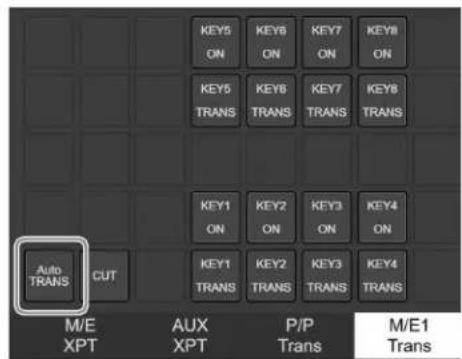


The button moves.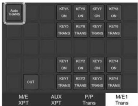
Note
If a button already exists at the destination frame, the buttons swap positions.
Editing Setup Data
Use the following procedure to edit existing setup data.
1 Select the setup data to edit in the setup data selection area on the setup screen.

2 Press the [Edit] button.

The screen switches to the edit screen to edit setup data.
3 Edit the setup data as described in "Creating Setup Data" (page 532).
4 Press the [Save] button.
The setup data is overwritten.
Selecting Setup Data to be Displayed on the Operation Screen
1 Select setup data to be displayed on the operation screen from the setup data selection area.
The background color of selected setup data changes to blue.
2 Press the [Apply] button.

A mark is displayed on the left of selected setup data.

3 Return to the operation screen, and check that the setup data is selected.

Other Setup Operations
The following setup operations are also supported.
Renaming Setup Data
1 Select the setup data to rename in the setup data selection area on the setup screen.
2 Press the [Edit Name] button.

A rename dialog appears.
3 Enter a name and press the [Apply] button. To exit without renaming, press the [Cancel] button or the [X] button.

The setup data is renamed.
Removing Setup Data
1 Select the setup data to remove in the setup data selection area on the setup screen.
2 Press the [Remove] button.

A confirmation dialog appears.
3 Press the [Yes] button to remove the setup data. To exit without removing, press the [No] button.

The setup data is removed.
Exporting Setup Data to a Computer
You can export setup data to a computer.
1 Select the setup data to export in the setup data selection area on the setup screen.
2 Press the [Export] button on the setup screen.

The setup data is downloaded as a .dat file to the computer.
Note
The download destination will vary depending on the computer settings.
Importing Setup Data
You can import setup data saved on a computer.
1 Press the [Import] button on the setup screen.

An import dialog appears.
2 Press [Select].

3 Select the setup data saved on a computer.
4 Press the [Import] button.

The setup data is imported, and the setup data name is displayed in the setup data selection area.
Appendix
Wipe Pattern List
The current image is represented by the black area of a pattern image and the new image is represented by the
white area. The wipe occurs in the direction of the arrow according to the transition.
Wipe Pattern List
Standard wipes
Enhanced wipes
26 27 29 49 300 301 302 303 304




Rotary wipes
100 101 102 103 104 105 106 107 150 151





156 158 160 162 516 518 604 606 624 661


Mosaic wipes
Random/diamond dust wipes
270 271 272 273 274


DME Wipe Pattern List
DME wipe patterns available in 1-channel mode
Slide
1001 1002 1003 1004 1005 1006 1007 1008


Squeeze
1021 1022 1023 1024 1025 1026 1027 1028 1029 1030



1031 1032 1033


Split

1011 1012 1013
Door



1041 1042 1043 1044 Flip tumble
1101 1102
Page turn





Roll








Frame in/out


Picture-in-picture
Mosaic
Defocus
DME wipe patterns available in 2-channel mode
Slide


2601 2602 2603 2604 2605 2606 2607 2608
Squeeze


2621 2622 2623 2624 2625 2626 2627 2628
Page turn
Roll
2749 2750
Frame in/out
Picture-in-picture 2651 2652
Crop slide 2661 2662
Brick
DME wipe patterns available in 3-channel mode
Brick 3601
Resizer DME Wipe Pattern List
Slide



7001 7002 7003 7004 7005 7006 7007 7008 Squeeze


7031
Frame in/out




7201 7202 7203 7204 7205 7206 7207 7208 7221 7222
7223 7224
Menus Recalled by Pressing a Button Twice
The control panel has buttons that can display a menu when double-pressed.
When the following buttons are pressed twice in quick succession, the corresponding menu is displayed.
“XX” represents the last recalled menu.
Notes
- Some button operations and menu settings may be disabled depending on the configuration of installed options and connected control panels.
- Assignment may be required depending on the button.
Cross-point control block/AUX bus control block
| Button Menu recalled | |
| Cross-point buttons assigned with [FM1] to [FM16] | Home > Frame Memory > FMx/FMx > Clip/Still > Recall(FMx/FMx = FM1/FM2 to FM15/FM16) |
| Cross-point buttons assigned with [CLIP1] to [CLIP4] | Home > Clip Player > Clipx/Clipx > Clip > Recall(Clipx/Clipx = Clip1/Clip2 to Clip3/Clip4) |
| Cross-point buttons assigned with [COL BKG1] | Home > Other Effects > Color Bkgd > Color Bkgd1 |
| Cross-point buttons assigned with [COL BKG2] | Home > Other Effects > Color Bkgd > Color Bkgd2 |
| [FMS1] delegation button a) | Home > Frame Memory > FM1/FM2 > Clip/Still > Record |
| [FMS2] delegation button a) | Home > Frame Memory > FM1/FM2 > Clip/Still > Record |
| [KEY1] to [KEY8] delegation buttons b) | Home > M/E-x > Keyx > XXHome > M/E-x Sub > Keyx > XXHome > P/P > Keyx > XXHome > P/P Sub > Keyx > XX(M/E-x = M/E-1 to M/E-5, Keyx = Key1 to Key8) |
a) 1st row delegation buttons in cross-point control block (key/AUX bus delegation mode) and 1st row/2nd row delegation buttons in AUX bus control block (AUX bus operation mode)
b) 1st row delegation buttons in cross-point control block (key/AUX bus delegation mode) and delegation buttons assigned to the cross-point pad/function button section in cross-point control block
Transition control block / transition control block (simple type)
| Button Menu recalled | |
| [KEY1] to [KEY8] buttons a) | Home > M/E-x > Keyx > XXHome > M/E-x Sub > Keyx > XXHome > P/P > Keyx > XXHome > P/P Sub > Keyx > XX(M/E-x = M/E-1 to M/E-5, Keyx = Key1 to Key8) |
| [PRIOR SET] button a) | Home > M/E-x > Common > Key Priority/Key AssignHome > M/E-x Sub > Common > Key Priority/Key AssignHome > P/P > Common > Key Priority/Key AssignHome > P/P Sub > Common > Key Priority/Key Assign(M/E-x = M/E-1 to M/E-5) |
| [KEY PRIOR] button a) | Home > M/E-x > Common > Key Priority/Key AssignHome > M/E-x Sub > Common > Key Priority/Key AssignHome > P/P > Common > Key Priority/Key AssignHome > P/P Sub > Common > Key Priority/Key Assign(M/E-x = M/E-1 to M/E-5) |
| [WIPE] button Home > M/E-x > Bus/Transition > Wipe | Main PatternHome > M/E-x Sub > Bus/Transition > Wipe > Main PatternHome > P/P > Bus/Transition > Wipe > Main PatternHome > P/P Sub > Bus/Transition > Wipe > Main Pattern(M/E-x = M/E-1 to M/E-5) |
| [DME WIPE] button Home > M/E-x > Bus/Transition > | DME Wipe > XXHome > M/E-x Sub > Bus/Transition > DME Wipe > XXHome > P/P > Bus/Transition > DME Wipe > XXHome > P/P Sub > Bus/Transition > DME Wipe > XX(M/E-x = M/E-1 to M/E-5) |
| [SUPER MIX] button Home > M/E-x > Bus/Transition > | Transition > Transition TypeHome > M/E-x Sub > Bus/Transition > Transition > Transition TypeHome > P/P > Bus/Transition > Transition > Transition TypeHome > P/P Sub > Bus/Transition > Transition > Transition Type(M/E-x = M/E-1 to M/E-5) |
| [PST COLOR MIX] button | Home > M/E-x > Bus/Transition > Transition > Transition TypeHome > M/E-x Sub > Bus/Transition > Transition > Transition TypeHome > P/P > Bus/Transition > Transition > Transition TypeHome > P/P Sub > Bus/Transition > Transition > Transition Type(M/E-x = M/E-1 to M/E-5) |
| [FM1&2 CLIP] to [FM15&16 CLIP] buttons | Home > M/E-x > Bus/Transition > Transition > Clip TransitionHome > M/E-x Sub > Bus/Transition > Transition > Clip TransitionHome > P/P > Bus/Transition > Transition > Clip TransitionHome > P/P Sub > Bus/Transition > Transition > Clip Transition(M/E-x = M/E-1 to M/E-5) |
a) Transition control block only
Flexi Pad control block
| Button Menu recalled | |
| [WIPE] button Home > M/E-x > Bus/Transition > Wipe | > Main PatternHome > M/E-x Sub > Bus/Transition > Wipe > Main PatternHome > P/P > Bus/Transition > Wipe > Main PatternHome > P/P Sub > Bus/Transition > Wipe > Main Pattern(M/E-x = M/E-1 to M/E-5) |
| [DME WIPE] button Home > M/E-x > Bus/Transition > | DME Wipe > XXHome > M/E-x Sub > Bus/Transition > DME Wipe > XXHome > P/P > Bus/Transition > DME Wipe > XXHome > P/P Sub > Bus/Transition > DME Wipe > XX(M/E-x = M/E-1 to M/E-5) |
| [SNAPSHOT] button Home > Register > Snapshot > Edit Register > XX | |
| [PNL MEM] button Home > Register > Panel Memory > | Edit Register > XX |
| [SHOTBOX] button Home > Register > Shotbox > Edit | Register > XX |
| [MCRO] button Home > Register > Macro > Edit Register > XX | |
| [KEY1] to [KEY8] buttons in the memory recall section | Home > M/E-x > Keyx > XXHome > M/E-x Sub > Keyx > XXHome > P/P > Keyx > XXHome > P/P Sub > Keyx > XX(M/E-x = M/E-1 to M/E-5, Keyx = Key1 to Key8) |
| [WIPE] button in the memory recall section | Home > M/E-x > Keyx > Transition > WipeHome > M/E-x Sub > Keyx > Transition > WipeHome > P/P > Keyx > Transition > WipeHome > P/P Sub > Keyx > Transition > Wipe(M/E-x = M/E-1 to M/E-5, Keyx = Key1 to Key8) |
| [DME WIPE] button in the memory recall section Home | > M/E-x > Keyx > Transition > 1ch PatternHome > M/E-x Sub > Keyx > Transition > 1ch PatternHome > P/P > Keyx > Transition > 1ch PatternHome > P/P Sub > Keyx > Transition > 1ch Pattern(M/E-x = M/E-1 to M/E-5, Keyx = Key1 to Key8) |
Key control block
| Button Menu recalled | |
| [KEY1] to [KEY8] buttons Home > M/E-x > Keyx > XX | Home > P/P > Keyx > XX(M/E-x = M/E-1 to M/E-5, Keyx = Key1 to Key8) |
| [LUM] button | Home > M/E-x > Keyx > Type > Type SelectHome > P/P > Keyx > Type > Type Select(M/E-x = M/E-1 to M/E-5, Keyx = Key1 to Key8) |
| [LIN] button Home > M/E-x > Keyx > Type > Type Select | Home > P/P > Keyx > Type > Type Select(M/E-x = M/E-1 to M/E-5, Keyx = Key1 to Key8) |
| [PTN] button Home > M/E-x > Keyx > Type > Type Select | Home > P/P > Keyx > Type > Type Select(M/E-x = M/E-1 to M/E-5, Keyx = Key1 to Key8) |
| [CRK] button Home > M/E-x > Keyx > Type > Chroma | AdjustHome > P/P > Keyx > Type > Chroma Adjust(M/E-x = M/E-1 to M/E-5, Keyx = Key1 to Key8) |
Key fader control block
| Button Menu recalled | |
| Key delegation buttons Home > M/E-x > Keyx > XX | Home > P/P > Keyx > XX(M/E-x = M/E-1 to M/E-5, Keyx = Key1 to Key8) |
| [WIPE] button Home > M/E-x > Keyx > Transition > Wipe | Home > P/P > Keyx > Transition > Wipe(M/E-x = M/E-1 to M/E-5, Keyx = Key1 to Key8) |
| [DME WIPE] button Home > M/E-x > Keyx > Transition | > 1ch PatternHome > P/P > Keyx > Transition > 1ch Pattern(M/E-x = M/E-1 to M/E-5, Keyx = Key1 to Key8) |
| [K-SS STORE] button a) | Home > Register > Key Snapshot > Edit Register > Browse |
a) When the [K-SS] button is lit only
Device control block
| Button Menu recalled | |
| [CH1] to [CH4] buttons in three-dimensional transform operation mode | Home > DME > Channelx > XX(Channelx = Channel1 to Channel4) |
| [CH1] to [CH12] buttons in device/frame memory/clip player operation mode | Home > External Device > Device > Cueup & Play |
| [FM1 CLIP] to [FM16 CLIP] buttons | Home > Frame Memory > FMx/FMx > Clip/Still > Recall(FMx/FMx = FM1/FM2 to FM15/FM16) |
| [CLIP1] to [CLIP4] buttons Home > Clip Player > Clipx/ | Clipx > Clip > Recall(Clipx/Clipx = Clip1/Clip2 to Clip3/Clip4) |
| [K1RSZ] to [K8RSZ] buttons | Home > M/E-x > Keyx > Resizer/Proc Key > Resizer Adjust/DME SelectHome > P/P > Keyx > Resizer/Proc Key > Resizer Adjust/DME Select(M/E-x = M/E-1 to M/E-5, Keyx = Key1 to Key8) |
Numeric keypad control block
| Button Menu recalled | |
| [EFF] button | Home > Register > Effect Timeline > Edit Register > Browse Multi Rgn |
| [SNAPSHOT] button | Home > Register > Snapshot > Edit Register > Browse Multi Rgn |
| [SHOTBOX] button | Home > Register > Shotbox > Edit Register > Browse |
| [MCRO] button | Home > Register > Macro > Edit Register > Browse |
| [PNL MEM] button | Register > Panel Memory > Edit Register > Browse |
Utility/shotbox control block
| Button Menu recalled | |
| [TRANS RATE1] to [TRANS RATE3] buttons | Home > Utility > Transition Rate |
| Memory recall buttons assigned with the following utility commands• M/E-x Key1 Preview to M/E-x Key8 Preview• P/P Key1 Preview to P/P Key8 Preview | Home > M/E-x > Keyx > XXHome > P/P > Keyx > XX(M/E-x = M/E-1 to M/E-5, Keyx = Key1 to Key8) |
Utility control block
| Button Menu recalled | |
| [UTIL/SBOX] button Home > Setup > Panel > Module > Utility Function Assign | |
| Memory recall buttons assigned with the following utility commands• M/E-x Key1 Preview to M/E-x Key8 Preview• P/P Key1 Preview to P/P Key8 Preview | Home > M/E-x > Keyx > XXHome > P/P > Keyx > XX(M/E-x = M/E-1 to M/E-5, Keyx = Key1 to Key8) |
Number of Switcher Resources
The number of resources that can be used will vary depending on the switcher configuration and system signal format. The maximum number of resources for 4K format (2160P) and HD format (1080P, 1080PsF, 1080i, 720P) are shown below.
Note
To use 4K formats, the MZS-X1500 4K Upgrade License (option) is required.
| Resource Switcher configuration | Half box | 1M/Ebox | 1M/Ebox+ cross-point box | 2M/Ebox | 2M/Ebox+ cross-point box | 3M/Ebox | 3M/Ebox+ cross-point box | 4M/Ebox | 4M/Ebox+ cross-point box | ||||||||||
| 4K | HD | 4K | HD | 4K | HD | 4K | HD | 4K | HD | 4K | HD | 4K | HD | 4K | HD | 4K | HD | ||
| Switcher banksa) | 1 2 | 2 4 3 | 6 4 6 | 5 6 6 | - 6 | - 6 | - | ||||||||||||
| When M/E split is enabled 2 | 4 4 6 | 6 6 6 | 6 6 6 | 6 - | 6 - | - | |||||||||||||
| Keysb) | 6 | 16 | 12 | 32 | 18 | 48 | 24 | 48 | 30 | 48 | 36 | - | 36 | - | 36 | - | 36 | - | |
| Keys configurable with a resizer | 4 | 16 | 8 | 32 | 12 | 48 | 16 | 48 | 20 | 48 | 24 | - | 24 | - | 24 | - | 24 | - | |
| Keys per switcher bank 6 8 | 6 8 6 | 8 6 8 | 6 8 6 | - 6 | - 6 | - | |||||||||||||
| Inputsc) | 16 | 32 | 32 | 64 | 48 | 96 | 64 | 128 | 80 | 160 | 96 | - | 112 | - | 128 | - | 144 | - | |
| Inputs configurable with a format converter d) | 8 | 16 | 16 | 32 | 24 | 48 | 32 | 64 | 40 | 80 | 48 | - | 56 | - | 64 | - | 72 | - | |
| Inputs configurable with a color corrector/HDR convertere) | 4 | 8 | 8 | 16 | 12 | 24 | 16 | 32 | 20 | 40 | 24 | - | 28 | - | 32 | - | 36 | - | |
| Outputs (Output)f | 16 | 32 | 32 | 64 | 16 | 32 | 32 | 64 | 32 | 64 | 48 | - | 48 | - | 64 | - | 64 | - | |
| Outputs configurable with a format converter j) | 8 | 16 | 16 | 32 | 8 | 16 | 16 | 32 | 16 | 32 | 24 | - | 24 | - | 32 | - | 32 | - | |
| Outputs configurable with a color corrector/HDR convertere) | 4 | 8 | 8 | 16 | 4 | 8 | 8 | 16 | 8 | 16 | 12 | - | 12 | - | 16 | - | 16 | - | |
| Dedicated outputs (Dedicated Out)f | - | - | - | - | 32 | 64 | 32 | 64 | 48 | 96 | 48 | - | 64 | - | 64 | - | 80 | - | |
| Outputs configurable with a format converter j) | - | - | - | - | 16 | 32 | 16 | 32 | 24 | 48 | 24 | - | 32 | - | 32 | - | 40 | - | |
| Outputs configurable with an HDR convertere) | - | - | - | - | 8 | 16 | 8 | 16 | 12 | 24 | 12 | - | 16 | - | 16 | - | 20 | - | |
| DME channelsg) | 2 4 | 2 4 4 | 4 4 4 | 4 4 4 | - 4 | - 4 | - | ||||||||||||
| DME channel 1 or 2 when enhanced function mode is enabled | - 3 | - 3 | - 3 | - 3 | - - - - - - - - - - - - - - - - - - - - - - - - - - - - - - - - - - - - - - - - - - - - - - - - - - - - - - - - - - - - - - - - - - - - - - - - - - - - - - - - - - - - - - - - - - - - - - - - - - - - - | ||||||||||||||
| DME channels 1 and 2 when enhanced function mode is enabled | - 2 | - 2 | - 2 | - 2 | - - - - - - - - - - - - - - - - - - - - - - - - - - - - - - - - - - - - - - - - - - - - - - - - - - - - - - - - - - - - - - - - - - - - - - - - - - - - - - - - - - - - - - - - - - - - - - - - - - | - | |||||||||||||
| DME channel 1 or 3 when enhanced function mode is enabled | 1 - | 1 - 3 | - 3 | - 3 | - 3 | - 3 | - 3 | - | |||||||||||
| DME channels 1 and 3 when enhanced function mode is enabled | - - - - 2 | - 2 | - 2 | - 2 | - 2 | - 2 | - 2 | - | |||||||||||
| Frame memory output channels | 6 | 16 | 6 | 16 | 12 | 16 | 12 | 16 | 12 | 16 | 12 | - | 12 | - | 12 | - | 12 | - | |
| Resource Switcher configuration | ||||||||||||||||||
| Half box | 1M/Ebox | 1M/Ebox+cross-point box | 2M/Ebox | 2M/Ebox+cross-point box | 3M/Ebox | 3M/Ebox+cross-point box | 4M/Ebox | 4M/Ebox+cross-point box | ||||||||||
| 4K | HD | 4K | HD | 4K | HD | 4K | HD | 4K | HD | 4K | HD | 4K | HD | 4K | HD | 4K | HD | |
| Clip player output channels h) | 2 4 | 2 4 2 | 4 2 4 | 2 4 2 | - 2 | - 2 | - 2 | - | ||||||||||
| Multi viewers i) | 1 2 | 2 4 3 | 4 4 4 | 4 4 4 | - 4 | - 4 | - 4 | - | ||||||||||
| Color backgrounds 1 2 1 2 1 2 | 1 2 1 | 2 1 | - 1 | - 1 | - 1 | - 1 | - 1 | - | - | |||||||||
a) You can change the switcher bank (M/E-1 to M/E-5, P/P) assignment in the Home > Setup > Switcher > Config > M/E Assign menu (19103.11). b) If the number of keys on a single switcher bank is four or lower, SL keys can be used. c) To use the cross-point box inputs, input signals must be assigned using the Home > Setup > Switcher > Box Settings > Re-Entry Source Assign menu (19103.52). d) A format converter cannot be used in the following cases: - When the system signal format is 2160P and the frequency is 29.97, 25, or 23.98 - When the system signal format is 720P - When the system signal format is 1080PsF and the input signal is IP e) To use the HDR converter function, the MZS-X1750 HDR Converter License (option) is required. When the system signal format is 720P, an HDR converter cannot be used. f) The number of outputs varies depending on the type of installed boards. For details, see "Output numbers (2160P)" (page 552) and "Output numbers (other than 2160P)" (page 557) in "Input/Output Numbers." g) To use the DME function, the MZS-X1610 3D DME License (option) is required. For 4K formats, either DMEs or SL keys can be enabled for each box. h) To use the clip player function, the MZS-X1800 Clip Player License (option) is required. i) In a multiple-box switcher configuration, you must configure a hardware block for use as a multi viewer or as a switcher bank. For details, see "Setting a Switcher Bank/Multi Viewer" (page 383). j) A format converter cannot be used in the following cases: - When the system signal format is 2160P and the frequency is 29.97, 25, or 23.98 - When the system signal format is 1080PsF or 720P
Input/Output Numbers
The input/output numbers will vary depending on the switcher configuration and system signal format.
Input numbers
Half-box configuration
| Source number | System signal format | |||||
| 2160P Other than 2160P | ||||||
| Logical box ID | Slot number | Port number | Logical box ID | Slot number | Port number | |
| 1 to 16 1 1 1 to | 16 1 1 1 to 32 | |||||
1M/E box configuration
| Source number | System signal format | |||||
| 2160P Other than 2160P | ||||||
| Logical box ID | Slot number | Port number | Logical box ID | Slot number | Port number | |
| 1 to 16 1 1 1 to | 16 1 1 1 to 16 | |||||
| 17 to 32 | 1 | 4 | 17 to 32 | 1 | 1 | 17 to 32 |
| 33 to 48 — — — 1 | 4 33 to 48 | |||||
| 49 to 64 — — — 1 | 4 49 to 64 | |||||
1M/E box + cross-point box configuration
| Source number | System signal format | |||||
| 2160P Other than 2160P | ||||||
| Logical box ID | Slot number | Port number | Logical box ID | Slot number | Port number | |
| 1 to 16 1 1 1 to | 16 1 1 1 to 16 | |||||
| 17 to 32 | 1 | 4 | 17 to 32 | 1 | 1 | 17 to 32 |
| 33 to 48 | 2 | 1 | 33 to 48 | 1 | 4 | 33 to 48 |
| 49 to 64 --- 1 | 4 49 to 64 | |||||
| 65 to 80 --- 2 | 1 65 to 80 | |||||
| 81 to 96 --- 2 | 1 81 to 96 | |||||
2M/E box configuration
| Source number | System signal format | |||||
| 2160P Other than 2160P | ||||||
| Logical box ID | Slot number | Port number | Logical box ID | Slot number | Port number | |
| 1 to 16 1 1 1 to | 16 1 1 1 to 16 | |||||
| 17 to 32 | 1 | 4 | 17 to 32 | 1 | 1 | 17 to 32 |
| 33 to 48 | 2 | 1 | 33 to 48 | 1 | 4 | 33 to 48 |
| 49 to 64 | 2 | 4 | 49 to 64 | 1 | 4 | 49 to 64 |
| 65 to 80 --- 2 | 1 65 to 80 | |||||
| 81 to 96 --- 2 | 1 81 to 96 | |||||
| 97 to 112 --- | 2 4 97 to 112 | |||||
| 113 to 128 --- | 2 4 113 to 128 | |||||
2M/E box + cross-point box configuration
| Source number | System signal format | |||||
| 2160P Other than 2160P | ||||||
| Logical box ID | Slot number | Port number | Logical box ID | Slot number | Port number | |
| 1 to 16 1 1 1 to | 16 1 1 1 to 16 | |||||
| 17 to 32 | 1 | 4 | 17 to 32 | 1 | 1 | 17 to 32 |
| 33 to 48 | 2 | 1 | 33 to 48 | 1 | 4 | 33 to 48 |
| 49 to 64 | 2 | 4 | 49 to 64 | 1 | 4 | 49 to 64 |
| 65 to 80 | 3 | 1 | 65 to 80 | 2 | 1 | 65 to 80 |
| 81 to 96 --- 2 | 1 81 to 96 | |||||
| 97 to 112 --- | 2 4 97 to 112 | |||||
| 113 to 128 --- | 2 4 113 to 128 | |||||
| 129 to 144 --- | 3 1 129 to 144 | |||||
| 129 to 160 --- | 3 1 129 to 160 | |||||
3M/E box configuration
| Source number | System signal format | ||
| 2160P | |||
| Logical box ID | Slot number | Port number | |
| 1 to 16 | 1 | 1 | 1 to 16 |
| 17 to 32 | 1 | 4 | 17 to 32 |
| 33 to 48 | 2 | 1 | 33 to 48 |
| 49 to 64 | 2 | 4 | 49 to 64 |
| 65 to 80 | 3 | 1 | 65 to 80 |
| 81 to 96 | 3 | 4 | 81 to 96 |
3M/E box + cross-point box configuration
| Source number | System signal format | ||
| 2160P | |||
| Logical box ID | Slot number | Port number | |
| 1 to 16 | 1 | 1 | 1 to 16 |
| 17 to 32 | 1 | 4 | 17 to 32 |
| 33 to 48 | 2 | 1 | 33 to 48 |
| 49 to 64 | 2 | 4 | 49 to 64 |
| 65 to 80 | 3 | 1 | 65 to 80 |
| 81 to 96 | 3 | 4 | 81 to 96 |
| 97 to 112 | 4 | 1 | 97 to 112 |
4M/E box configuration
| Source number | System signal format | ||
| 2160P | |||
| Logical box ID | Slot number | Port number | |
| 1 to 16 | 1 | 1 | 1 to 16 |
| 17 to 32 | 1 | 4 | 17 to 32 |
| 33 to 48 | 2 | 1 | 33 to 48 |
| 49 to 6465 to 80 3 1 65 | 2to 80 | 4 | 49 to 64 |
| 81 to 96 3 4 81 | to 96 | ||
| 97 to 112 4 1 97 | to 112 | ||
| 113 to 128 4 4 | 113 to 128 | ||
4M/E box + cross-point box configuration
| Source number | System signal format | ||
| 2160P | |||
| Logical box ID Slot number | Port number | ||
| 1 to 16 1 1 1 to | 16 | ||
| 17 to 32 1 4 17 | to 32 | ||
| 33 to 48 2 1 33 | to 48 | ||
| 49 to 64 2 4 49 | to 64 | ||
| 65 to 80 3 1 65 | to 80 | ||
| 81 to 96 3 4 81 | to 96 | ||
| 97 to 112 4 1 97 | to 112 | ||
| 113 to 128 4 4 | 113 to 128 | ||
| 129 to 144 5 1 | 129 to 144 | ||
Output numbers (2160P)
Half-box configuration
| Output Dedicated Output | |||
| No. | System signal format | ||
| 2160P 2160P | |||
| Logical box ID | Slot number | Port number | |
| 1 to 16 | 1 | 1 | 1 to 16 |
| No. | System signal format | ||
| Logical box ID | Slot number | Port number | |
| 1 to 4 | - | - | - |
| 5 to 8 | - | - | - |
| 9 to 12 | - | - | - |
| 13 to 16 | - | - | - |
1M/E box configuration
| Output Dedicated Output | |||
| No. | System signal format | ||
| 2160P 2160P | |||
| Logical box ID | Slot number | Port number | |
| 1 to 16 1 | 1 1 to 16 1 to 4 — — | ||
| 17 to 32 | 1 | 4 | 17 to 32 |
| No. | System signal format | ||
| Logical box ID | Slot number | Port number | |
| 5 to 8 | - | - | - |
| 9 to 12 | -- | ||
| 13 to 16 | ---- | ||
| 17 to 20 | ---- | ||
| 21 to 24 | ---- | ||
| 25 to 28 | ---- | ||
| 29 to 32 | ---- | ||
1M/E box + cross-point box configuration
| Output Dedicated Output | |||
| No. | System signal format | ||
| 2160P 2160P | |||
| Logical box ID | Slot number | Port number | |
| 1 to 4 | 1 | 1 | 1 to 4 |
| 5 to 8 | 1 | 1 | 9 to 12 |
| 9 to 12 | 1 | 4 | 17 to 20 |
| 13 to 16 | 1 | 4 | 25 to 28 |
| No. | System signal format | ||
| Logical box ID | Slot number | Port number | |
| 1 to 4 | 1 | 1 | 5 to 8 |
| 5 to 8 | 1 | 1 | 13 to 16 |
| 9 to 12 | 1 | 4 | 21 to 24 |
| 13 to 16 | 1 | 4 | 29 to 32 |
| 17 to 32 | 2 | 1 | 33 to 48 |
2M/E box configuration
| Output Dedicated Output | |||
| No. | System signal format | ||
| 2160P 2160P | |||
| Logical box ID | Slot number | Port number | |
| 1 to 4 | 1 | 1 | 1 to 4 |
| 5 to 8 | 1 | 1 | 9 to 12 |
| 9 to 12 | 1 | 4 | 17 to 20 |
| 13 to 16 | 1 | 4 | 25 to 28 |
| 17 to 20 | 2 | 1 | 33 to 36 |
| 21 to 24 | 2 | 1 | 41 to 44 |
| 25 to 28 | 2 | 4 | 49 to 52 |
| 29 to 32 | 2 | 4 | 57 to 60 |
| No. | System signal format | ||
| Logical box ID | Slot number | Port number | |
| 1 to 4 | 1 | 1 | 5 to 8 |
| 5 to 8 | 1 | 1 | 13 to 16 |
| 9 to 12 | 1 | 4 | 21 to 24 |
| 13 to 16 | 1 | 4 | 29 to 32 |
| 17 to 20 | 2 | 1 | 37 to 40 |
| 21 to 24 | 2 | 1 | 45 to 48 |
| 25 to 28 | 2 | 4 | 53 to 56 |
| 29 to 32 | 2 | 4 | 61 to 64 |
2M/E box + cross-point box configuration
| Output Dedicated Output | |||
| No. | System signal format | ||
| 2160P 2160P | |||
| Logical box ID | Slot number | Port number | |
| 1 to 4 | 1 | 1 | 1 to 4 |
| 5 to 8 | 1 | 1 | 9 to 12 |
| 9 to 12 | 1 | 4 | 17 to 20 |
| 13 to 16 | 1 | 4 | 25 to 28 |
| 17 to 20 | 2 | 1 | 33 to 36 |
| 21 to 24 | 2 | 1 | 41 to 44 |
| 25 to 28 | 2 | 4 | 49 to 52 |
| 29 to 32 | 2 | 4 | 57 to 60 |
| No. | System signal format | ||
| Logical box ID | Slot number | Port number | |
| 1 to 4 | 1 | 1 | 5 to 8 |
| 5 to 8 | 1 | 1 | 13 to 16 |
| 9 to 12 | 1 | 4 | 21 to 24 |
| 13 to 16 | 1 | 4 | 29 to 32 |
| 17 to 20 | 2 | 1 | 37 to 40 |
| 21 to 24 | 2 | 1 | 45 to 48 |
| 25 to 28 | 2 | 4 | 53 to 56 |
| 29 to 32 | 2 | 4 | 61 to 64 |
| 33 to 48 | 3 1 65 to 80 | ||
3M/E box configuration
| Output Dedicated Output | |||
| No. | System signal format | ||
| 2160P 2160P | |||
| Logical box ID | Slot number | Port number | |
| 1 to 4 | 1 | 1 | 1 to 4 |
| 5 to 8 | 1 | 1 | 9 to 12 |
| 9 to 12 | 1 | 4 | 17 to 20 |
| 13 to 16 | 1 | 4 | 25 to 28 |
| 17 to 20 | 2 | 1 | 33 to 36 |
| 21 to 24 | 2 | 1 | 41 to 44 |
| 25 to 28 | 2 | 4 | 49 to 52 |
| 29 to 32 | 2 | 4 | 57 to 60 |
| 33 to 36 | 3 | 1 | 65 to 68 |
| 37 to 40 | 3 | 1 | 73 to 76 |
| 41 to 44 | 3 | 4 | 81 to 84 |
| 45 to 48 | 3 | 4 | 89 to 92 |
| No. | System signal format | ||
| Logical box ID | Slot number | Port number | |
| 1 to 4 | 1 | 1 | 5 to 8 |
| 5 to 8 | 1 | 1 | 13 to 16 |
| 9 to 12 | 1 | 4 | 21 to 24 |
| 13 to 16 | 1 | 4 | 29 to 32 |
| 17 to 20 | 2 | 1 | 37 to 40 |
| 21 to 24 | 2 | 1 | 45 to 48 |
| 25 to 28 | 2 | 4 | 53 to 56 |
| 29 to 32 | 2 | 4 | 61 to 64 |
| 33 to 36 | 3 | 1 | 69 to 72 |
| 37 to 40 | 3 | 1 | 77 to 80 |
| 41 to 44 | 3 | 4 | 85 to 88 |
| 45 to 48 | 3 | 4 | 93 to 96 |
3M/E box + cross-point box configuration
| Output Dedicated Output | |||
| No. | System signal format | ||
| 2160P 2160P | |||
| Logical box ID | Slot number | Port number | |
| 1 to 4 | 1 | 1 | 1 to 4 |
| 5 to 8 | 1 | 1 | 9 to 12 |
| 9 to 12 | 1 | 4 | 17 to 20 |
| 13 to 16 | 1 | 4 | 25 to 28 |
| 17 to 20 | 2 | 1 | 33 to 36 |
| 21 to 24 | 2 | 1 | 41 to 44 |
| 25 to 28 | 2 | 4 | 49 to 52 |
| 29 to 32 | 2 | 4 | 57 to 60 |
| 33 to 36 | 3 | 1 | 65 to 68 |
| 37 to 40 | 3 | 1 | 73 to 76 |
| 41 to 44 | 3 | 4 | 81 to 84 |
| 45 to 48 | 3 | 4 | 89 to 92 |
| No. | System signal format | ||
| Logical box ID | Slot number | Port number | |
| 1 to 4 | 1 | 1 | 5 to 8 |
| 5 to 8 | 1 | 1 | 13 to 16 |
| 9 to 12 | 1 | 4 | 21 to 24 |
| 13 to 16 | 1 | 4 | 29 to 32 |
| 17 to 20 | 2 | 1 | 37 to 40 |
| 21 to 24 | 2 | 1 | 45 to 48 |
| 25 to 28 | 2 | 4 | 53 to 56 |
| 29 to 32 | 2 | 4 | 61 to 64 |
| 33 to 36 | 3 | 1 | 69 to 72 |
| 37 to 40 | 3 | 1 | 77 to 80 |
| 41 to 44 | 3 | 4 | 85 to 88 |
| 45 to 48 | 3 | 4 | 93 to 96 |
| 49 to 64 | 4 1 97 to 112 | ||
4M/E box configuration
| Output Dedicated Output | |||
| No. | System signal format | ||
| 2160P 2160P | |||
| Logical box ID | Slot number | Port number | |
| 1 to 4 | 1 | 1 | 1 to 4 |
| 5 to 8 | 1 | 1 | 9 to 12 |
| 9 to 12 | 1 | 4 | 17 to 20 |
| 13 to 16 | 1 | 4 | 25 to 28 |
| 17 to 20 | 2 | 1 | 33 to 36 |
| 21 to 24 | 2 | 1 | 41 to 44 |
| 25 to 28 | 2 | 4 | 49 to 52 |
| 29 to 32 | 2 | 4 | 57 to 60 |
| 33 to 36 | 3 | 1 | 65 to 68 |
| 37 to 40 | 3 | 1 | 73 to 76 |
| 41 to 44 | 3 | 4 | 81 to 84 |
| 45 to 48 | 3 | 4 | 89 to 92 |
| 49 to 52 | 4 | 1 | 97 to 100 |
| 53 to 56 | 4 | 1 | 105 to 108 |
| 57 to 60 | 4 | 4 | 113 to 116 |
| 61 to 64 | 4 | 4 | 121 to 124 |
| No. | System signal format | ||
| Logical box ID | Slot number | Port number | |
| 1 to 4 | 1 | 1 | 5 to 8 |
| 5 to 8 | 1 | 1 | 13 to 16 |
| 9 to 12 | 1 | 4 | 21 to 24 |
| 13 to 16 | 1 | 4 | 29 to 32 |
| 17 to 20 | 2 | 1 | 37 to 40 |
| 21 to 24 | 2 | 1 | 45 to 48 |
| 25 to 28 | 2 | 4 | 53 to 56 |
| 29 to 32 | 2 | 4 | 61 to 64 |
| 33 to 36 | 3 | 1 | 69 to 72 |
| 37 to 40 | 3 | 1 | 77 to 80 |
| 41 to 44 | 3 | 4 | 85 to 88 |
| 45 to 48 | 3 | 4 | 93 to 96 |
| 49 to 52 | 4 | 1 | 101 to 104 |
| 53 to 56 | 4 | 1 | 109 to 112 |
| 57 to 60 | 4 | 4 | 117 to 120 |
| 61 to 64 | 4 | 4 | 125 to 128 |
4M/E box + cross-point box configuration
| Output Dedicated Output | |||
| No. | System signal format | ||
| 2160P 2160P | |||
| Logical box ID | Slot number | Port number | |
| 1 to 4 | 1 | 1 | 1 to 4 |
| 5 to 8 | 1 | 1 | 9 to 12 |
| 9 to 12 | 1 | 4 | 17 to 20 |
| 13 to 16 | 1 | 4 | 25 to 28 |
| 17 to 20 | 2 | 1 | 33 to 36 |
| 21 to 24 | 2 | 1 | 41 to 44 |
| 25 to 28 | 2 | 4 | 49 to 52 |
| 29 to 32 | 2 | 4 | 57 to 60 |
| 33 to 36 | 3 | 1 | 65 to 68 |
| 37 to 40 | 3 | 1 | 73 to 76 |
| 41 to 44 | 3 | 4 | 81 to 84 |
| 45 to 48 | 3 | 4 | 89 to 92 |
| 49 to 52 | 4 | 1 | 97 to 100 |
| 53 to 56 | 4 | 1 | 105 to 108 |
| 57 to 60 | 4 | 4 | 113 to 116 |
| 61 to 64 | 4 | 4 | 121 to 124 |
| No. | System signal format | ||
| Logical box ID | Slot number | Port number | |
| 1 to 4 | 1 | 1 | 5 to 8 |
| 5 to 8 | 1 | 1 | 13 to 16 |
| 9 to 12 | 1 | 4 | 21 to 24 |
| 13 to 16 | 1 | 4 | 29 to 32 |
| 17 to 20 | 2 | 1 | 37 to 40 |
| 21 to 24 | 2 | 1 | 45 to 48 |
| 25 to 28 | 2 | 4 | 53 to 56 |
| 29 to 32 | 2 | 4 | 61 to 64 |
| 33 to 36 | 3 | 1 | 69 to 72 |
| 37 to 40 | 3 | 1 | 77 to 80 |
| 41 to 44 | 3 | 4 | 85 to 88 |
| 45 to 48 | 3 | 4 | 93 to 96 |
| 49 to 52 | 4 | 1 | 101 to 104 |
| 53 to 56 | 4 | 1 | 109 to 112 |
| 57 to 60 | 4 | 4 | 117 to 120 |
| 61 to 64 | 4 | 4 | 125 to 128 |
| 65 to 80 | 5 1 129 to 144 | ||
Output numbers (other than 2160P)
Half-box configuration
- Logical box with ID of 1 is IP
| Output Dedicated Output | ||||
| No. System signal format No. System signal format | ||||
| Other than 2160P Other than 2160P | ||||
| Logical box ID IP | /SDI Slot | number | Port number | |
| 1 to 32 | 1 | IP | 1 | 1 to 32 |
- Logical box with ID of 1 is SDI
| Output Dedicated Output | ||||
| No. System signal format No. System signal format | ||||
| Other than 2160P Other than 2160P | ||||
| Logical box ID IP | /SDI Slot | number | Port number | |
| 1 to 16 | 1 | SDI | 1 | 1 to 16 |
1M/E box configuration
- Logical box with ID of 1 is IP
| Output Dedicated Output | ||||
| No. | System signal format | |||
| Other than 2160P | ||||
| Logical box ID | IP/SDI | Slot number | Port number | |
| 1 to 32 | 1 | IP | 1 | 1 to 32 |
| 33 to 64 | 1 | IP | 4 | 33 to 64 |
- Logical box with ID of 1 is SDI
| Output Dedicated Output | ||||
| No. | System signal format | |||
| Other than 2160P | ||||
| Logical box ID | IP/SDI | Slot number | Port number | |
| 1 to 16 | 1 | SDI | 1 | 1 to 16 |
| 17 to 32 | 1 | SDI | 4 | 17 to 32 |
| Logical box ID IP/SDI Slot number | Port number | |||
| 1 to 32 | 1 | IP | 1 | - |
| Logical box ID IP/SDI Slot number | Port number | |||
| 1 to 32 | 1 | SDI | 1 | - |
| No. | System signal format | |||
| Other than 2160P | ||||
| Logical box ID | IP/SDI | Slot number | Port number | |
| 1 to 32 | 1 | IP | 1 | - |
| 33 to 64 | 1 | IP | 4 | - |
| No. | System signal format | |||
| Other than 2160P | ||||
| Logical box ID | IP/SDI | Slot number | Port number | |
| 1 to 16 | 1 | SDI | 1 | - |
| 17 to 32 | 1 | SDI | 4 | - |
1M/E box + cross-point box configuration
- Logical box with ID of 1 is IP, logical box with ID of 2 is IP
| Output Dedicated Output | ||||
| No. | System signal format | |||
| Other than 2160P Other than 2160P | ||||
| Logical box ID | IP/SDI Slot number | Port number | ||
| 1 to 8 | 1 | IP | 1 | 1 to 8 |
| 9 to 16 | 1 | IP | 1 | 17 to 24 |
| 17 to 24 | 1 | IP | 4 | 33 to 40 |
| 25 to 32 | 1 | IP | 4 | 49 to 56 |
| 33 to 64 | 2 | IP | 1 | - |
| No. | System signal format | |||
| Logical box ID IP/SDI Slot number | Port number | |||
| 1 to 8 | 1 | IP | 1 | 9 to 16 |
| 9 to 16 | 1 | IP | 1 | 25 to 32 |
| 17 to 24 | 1 | IP | 4 | 41 to 48 |
| 25 to 32 | 1 | IP | 4 | 57 to 64 |
| 33 to 64 | 2 | IP | 1 | 65 to 96 |
- Logical box with ID of 1 is IP, logical box with ID of 2 is SDI
| Output Dedicated Output | ||||
| No. | System signal format | |||
| Other than 2160P Other than 2160P | ||||
| Logical box ID | IP/SDI Slot number | Port number | ||
| 1 to 8 | 1 | IP | 1 | 1 to 8 |
| 9 to 16 | 1 | IP | 1 | 17 to 24 |
| 17 to 24 | 1 | IP | 4 | 33 to 40 |
| 25 to 32 | 1 | IP | 4 | 49 to 56 |
| 33 to 48 | 2 | SDI | 1 | - |
| No. | System signal format | |||
| Logical box ID | IP/SDI Slot number | Port number | ||
| 1 to 8 | 1 | IP | 1 | 9 to 16 |
| 9 to 16 | 1 | IP | 1 | 25 to 32 |
| 17 to 24 | 1 | IP | 4 | 41 to 48 |
| 25 to 32 | 1 | IP | 4 | 57 to 64 |
| 33 to 48 | 2 | SDI | 1 | 65 to 80 |
- Logical box with ID of 1 is SDI, logical box with ID of 2 is IP
| Output Dedicated Output | ||||
| No. | System signal format | |||
| Other than 2160P Other than 2160P | ||||
| Logical box ID IP/SDI Slot number | Port number | |||
| 1 to 16 | 1 | SDI | 1 | 1 to 16 |
| 17 to 32 | 1 | SDI | 4 | 17 to 32 |
| 33 to 64 | 2 | IP | 1 | - |
| No. | System signal format | |||
| Logical box ID | IP/SDI Slot number | Port number | ||
| 1 to 32 | 2 | IP | 1 | 33 to 64 |
- Logical box with ID of 1 is SDI, logical box with ID of 2 is SDI
| Output Dedicated Output | ||||
| No. | System signal format | |||
| Other than 2160P Other than 2160P | ||||
| Logical box ID IP/SDI Slot number | Port number | |||
| 1 to 16 | 1 | SDI | 1 | 1 to 16 |
| 17 to 32 | 1 | SDI | 4 | 17 to 32 |
| 33 to 48 | 2 | SDI | 1 | - |
| No. | System signal format | |||
| Logical box ID IP/SDI Slot number | Port number | |||
| 1 to 16 | 2 | SDI | 1 | 33 to 48 |
2M/E box configuration
- Logical box with ID of 1 is IP, logical box with ID of 2 is IP
| Output Dedicated Output | ||||
| No. | System signal format | |||
| Other than 2160P Other than 2160P | ||||
| Logical box ID | IP/SDI Slot number | Port number | ||
| 1 to 8 | 1 | IP | 1 | 1 to 8 |
| 9 to 16 | 1 | IP | 1 | 17 to 24 |
| 17 to 24 | 1 | IP | 4 | 33 to 40 |
| 25 to 32 | 1 | IP | 4 | 49 to 56 |
| 33 to 40 | 2 | IP | 1 | 65 to 72 |
| 41 to 48 | 2 | IP | 1 | 81 to 88 |
| 49 to 56 | 2 | IP | 4 | 97 to 104 |
| 57 to 64 | 2 | IP | 4 | 113 to 120 |
| No. | System signal format | |||
| Logical box ID | IP/SDI Slot number | Port number | ||
| 1 to 8 | 1 | IP | 1 | 9 to 16 |
| 9 to 16 | 1 | IP | 1 | 25 to 32 |
| 17 to 24 | 1 | IP | 4 | 41 to 48 |
| 25 to 32 | 1 | IP | 4 | 57 to 64 |
| 33 to 40 | 2 | IP | 1 | 73 to 80 |
| 41 to 48 | 2 | IP | 1 | 89 to 96 |
| 49 to 56 | 2 | IP | 4 | 105 to 112 |
| 57 to 64 | 2 | IP | 4 | 121 to 128 |
- Logical box with ID of 1 is IP, logical box with ID of 2 is SDI
| Output Dedicated Output | ||||
| No. | System signal format | |||
| Other than 2160P Other than 2160P | ||||
| Logical box ID | IP/SDI Slot number | Port number | ||
| 1 to 8 | 1 | IP | 1 | 1 to 8 |
| 9 to 16 | 1 | IP | 1 | 17 to 24 |
| 17 to 24 | 1 | IP | 4 | 33 to 40 |
| 25 to 32 | 1 | IP | 4 | 49 to 56 |
| 33 to 48 | 2 | SDI | 1 | 65 to 80 |
| 49 to 64 | 2 | SDI | 4 | 81 to 96 |
| No. | System signal format | |||
| Logical box ID | IP/SDI Slot number | Port number | ||
| 1 to 8 | 1 | IP | 1 | 9 to 16 |
| 9 to 16 | 1 | IP | 1 | 25 to 32 |
| 17 to 24 | 1 | IP | 4 | 41 to 48 |
| 25 to 32 | 1 | IP | 4 | 57 to 64 |
| 33 to 48 | 2 | SDI | 1 | - |
| 49 to 64 | 2 | SDI | 4 | - |
- Logical box with ID of 1 is SDI, logical box with ID of 2 is IP
| Output Dedicated Output | ||||
| No. | System signal format | |||
| Other than 2160P Other than 2160P | ||||
| Logical box ID | IP/SDI Slot number | Port number | ||
| 1 to 16 | 1 | SDI | 1 | 1 to 16 |
| 17 to 32 | 1 | SDI | 4 | 17 to 32 |
| 33 to 40 | 2 | IP | 1 | 33 to 40 |
| 41 to 48 | 2 | IP | 1 | 49 to 56 |
| 49 to 56 | 2 | IP | 4 | 65 to 72 |
| 57 to 64 | 2 | IP | 4 | 81 to 88 |
| No. | System signal format | |||
| Logical box ID | IP/SDI Slot number | Port number | ||
| 1 to 8 | 2 | IP | 1 | 41 to 48 |
| 9 to 16 | 2 | IP | 1 | 57 to 64 |
| 17 to 24 | 2 | IP | 4 | 73 to 80 |
| 25 to 32 | 2 | IP | 4 | 89 to 96 |
- - Logical box with ID of 1 is SDI, logical box with ID of 2 is SDI
| Output Dedicated Output | ||||
| No. | System signal format | |||
| Other than 2160P Other than 2160P | ||||
| Logical box ID IP/SDI Slot | Port number | |||
| 1 to 16 | 1 | SDI | 1 | 1 to 16 |
| 17 to 32 | 1 | SDI | 4 | 17 to 32 |
| 33 to 48 | 2 | SDI | 1 | 33 to 48 |
| 49 to 64 | 2 | SDI | 4 | 49 to 64 |
| No. | System signal format | |||
| Logical box ID | IP/SDI | Slot number | Port number | |
| 1 to 16 | 1 | SDI | 1 | - |
| 17 to 32 | 1 | SDI | 4 | - |
| 33 to 48 | 2 | SDI | 1 | - |
| 49 to 64 | 2 | SDI | 4 | - |
2M/E box + cross-point box configuration
- Logical box with ID of 1 is IP, logical box with ID of 2 is IP, logical box with ID of 3 is IP
| Output Dedicated Output | ||||
| No. | System signal format | |||
| Other than 2160P Other than 2160P | ||||
| Logical box ID | IP/SDI Slot number | Port number | ||
| 1 to 8 | 1 | IP | 1 | 1 to 8 |
| 9 to 16 | 1 | IP | 1 | 17 to 24 |
| 17 to 24 | 1 | IP | 4 | 33 to 40 |
| 25 to 32 | 1 | IP | 4 | 49 to 56 |
| 33 to 40 | 2 | IP | 1 | 65 to 72 |
| 41 to 48 | 2 | IP | 1 | 81 to 88 |
| 49 to 56 | 2 | IP | 4 | 97 to 104 |
| 57 to 64 | 2 | IP | 4 | 113 to 120 |
| 65 to 80 | 3 | IP | 1 | - |
| No. | System signal format | |||
| Logical box ID | IP/SDI Slot number | Port number | ||
| 1 to 8 | 1 | IP | 1 | 9 to 16 |
| 9 to 16 | 1 | IP | 1 | 25 to 32 |
| 17 to 24 | 1 | IP | 4 | 41 to 48 |
| 25 to 32 | 1 | IP | 4 | 57 to 64 |
| 33 to 40 | 2 | IP | 1 | 73 to 80 |
| 41 to 48 | 2 | IP | 1 | 89 to 96 |
| 49 to 56 | 2 | IP | 4 | 105 to 112 |
| 57 to 64 | 2 | IP | 4 | 121 to 128 |
| 65 to 96 | 3 | IP | 1 | 129 to 160 |
- - Logical box with ID of 1 is IP, logical box with ID of 2 is IP, logical box with ID of 3 is SDI
| Output Dedicated Output | ||||
| No. | System signal format | |||
| Other than 2160P Other than 2160P | ||||
| Logical box ID | IP/SDI Slot number | Port number | ||
| 1 to 8 | 1 | IP | 1 | 1 to 8 |
| 9 to 16 | 1 | IP | 1 | 17 to 24 |
| 17 to 24 | 1 | IP | 4 | 33 to 40 |
| 25 to 32 | 1 | IP | 4 | 49 to 56 |
| 33 to 40 | 2 | IP | 1 | 65 to 72 |
| 41 to 48 | 2 | IP | 1 | 81 to 88 |
| 49 to 56 | 2 | IP | 4 | 97 to 104 |
| 57 to 64 | 2 | IP | 4 | 113 to 120 |
| 65 to 80 | 3 | SDI | 1 | - |
| No. | System signal format | |||
| Logical box ID | IP/SDI Slot number | Port number | ||
| 1 to 8 | 1 | IP | 1 | 9 to 16 |
| 9 to 16 | 1 | IP | 1 | 25 to 32 |
| 17 to 24 | 1 | IP | 4 | 41 to 48 |
| 25 to 32 | 1 | IP | 4 | 57 to 64 |
| 33 to 40 | 2 | IP | 1 | 73 to 80 |
| 41 to 48 | 2 | IP | 1 | 89 to 96 |
| 49 to 56 | 2 | IP | 4 | 105 to 112 |
| 57 to 64 | 2 | IP | 4 | 121 to 128 |
| 65 to 80 | 3 | SDI | 1 | 129 to 144 |
- Logical box with ID of 1 is IP, logical box with ID of 2 is SDI, logical box with ID of 3 is IP
| Output Dedicated Output | ||||
| No. | System signal format | |||
| Other than 2160P Other than 2160P | ||||
| Logical box ID | IP/SDI Slot number | Port number | ||
| 1 to 8 | 1 | IP | 1 | 1 to 8 |
| 9 to 16 | 1 | IP | 1 | 17 to 24 |
| 17 to 24 | 1 | IP | 4 | 33 to 40 |
| 25 to 32 | 1 | IP | 4 | 49 to 56 |
| 33 to 48 | 2 | SDI | 1 | 65 to 80 |
| 49 to 64 | 2 | SDI | 4 | 81 to 96 |
| 65 to 80 | 3 | IP | 1 | - |
| No. | System signal format | |||
| Logical box ID | IP/SDI Slot number | Port number | ||
| 1 to 8 | 1 | IP | 1 | 9 to 16 |
| 9 to 16 | 1 | IP | 1 | 25 to 32 |
| 17 to 24 | 1 | IP | 4 | 41 to 48 |
| 25 to 32 | 1 | IP | 4 | 57 to 64 |
| 33 to 64 | 3 | IP | 1 | 97 to 128 |
- Logical box with ID of 1 is IP, logical box with ID of 2 is SDI, logical box with ID of 3 is SDI
| Output Dedicated Output | ||||
| No. | System signal format | |||
| Other than 2160P Other than 2160P | ||||
| Logical box ID | IP/SDI Slot number | Port number | ||
| 1 to 8 | 1 | IP | 1 | 1 to 8 |
| 9 to 16 | 1 | IP | 1 | 17 to 24 |
| 17 to 24 | 1 | IP | 4 | 33 to 40 |
| 25 to 32 | 1 | IP | 4 | 49 to 56 |
| 33 to 48 | 2 | SDI | 1 | 65 to 80 |
| 49 to 64 | 2 | SDI | 4 | 81 to 96 |
| 65 to 80 | 3 | SDI | 1 | - |
| No. | System signal format | |||
| Logical box ID | IP/SDI Slot number | Port number | ||
| 1 to 8 | 1 | IP | 1 | 9 to 16 |
| 9 to 16 | 1 | IP | 1 | 25 to 32 |
| 17 to 24 | 1 | IP | 4 | 41 to 48 |
| 25 to 32 | 1 | IP | 4 | 57 to 64 |
| 33 to 48 | 3 | SDI | 1 | 97 to 112 |
- Logical box with ID of 1 is SDI, logical box with ID of 2 is IP, logical box with ID of 3 is IP
| Output Dedicated Output | ||||
| No. | System signal format | |||
| Other than 2160P Other than 2160P | ||||
| Logical box ID | IP/SDI Slot number | Port number | ||
| 1 to 16 | 1 | SDI | 1 | 1 to 16 |
| 17 to 32 | 1 | SDI | 4 | 17 to 32 |
| 33 to 40 | 2 | IP | 1 | 33 to 40 |
| 41 to 48 | 2 | IP | 1 | 49 to 56 |
| 49 to 56 | 2 | IP | 4 | 65 to 72 |
| 57 to 64 | 2 | IP | 4 | 81 to 88 |
| 65 to 80 | 3 | IP | 1 | - |
| No. | System signal format | |||
| Logical box ID | IP/SDI Slot number | Port number | ||
| 1 to 8 | 2 | IP | 1 | 41 to 48 |
| 9 to 16 | 2 | IP | 1 | 57 to 64 |
| 17 to 24 | 2 | IP | 4 | 73 to 80 |
| 25 to 32 | 2 | IP | 4 | 89 to 96 |
| 33 to 64 | 3 | IP | 1 | 97 to 128 |
- Logical box with ID of 1 is SDI, logical box with ID of 2 is IP, logical box with ID of 3 is SDI
| Output Dedicated Output | ||||
| No. | System signal format | |||
| Other than 2160P Other than 2160P | ||||
| Logical box ID | IP/SDI Slot number | Port number | ||
| 1 to 16 | 1 | SDI | 1 | 1 to 16 |
| 17 to 32 | 1 | SDI | 4 | 17 to 32 |
| 33 to 40 | 2 | IP | 1 | 33 to 40 |
| 41 to 48 | 2 | IP | 1 | 49 to 56 |
| 49 to 56 | 2 | IP | 4 | 65 to 72 |
| 57 to 64 | 2 | IP | 4 | 81 to 88 |
| 65 to 80 | 3 | SDI | 1 | - |
| No. | System signal format | |||
| Logical box ID | IP/SDI Slot number | Port number | ||
| 1 to 8 | 2 | IP | 1 | 41 to 48 |
| 9 to 16 | 2 | IP | 1 | 57 to 64 |
| 17 to 24 | 2 | IP | 4 | 73 to 80 |
| 25 to 32 | 2 | IP | 4 | 89 to 96 |
| 33 to 48 | 3 | SDI | 1 | 97 to 112 |
- Logical box with ID of 1 is SDI, logical box with ID of 2 is SDI, logical box with ID of 3 is IP
| Output Dedicated Output | ||||
| No. | System signal format | |||
| Other than 2160P Other than 2160P | ||||
| Logical box ID IP/SDI Slot number | Port number | |||
| 1 to 16 | 1 | SDI | 1 | 1 to 16 |
| 17 to 32 | 1 | SDI | 4 | 17 to 32 |
| 33 to 48 | 2 | SDI | 1 | 33 to 48 |
| 49 to 64 | 2 | SDI | 4 | 49 to 64 |
| 65 to 80 | 3 IP 1 – | |||
| No. | System signal format | |||
| Logical box ID | IP/SDI Slot number | Port number | ||
| 1 to 32 | 3 | IP | 1 | 65 to 96 |
- Logical box with ID of 1 is SDI, logical box with ID of 2 is SDI, logical box with ID of 3 is SDI
| Output Dedicated Output | ||||
| No. | System signal format | |||
| Other than 2160P Other than 2160P | ||||
| Logical box ID | IP/SDI Slot number | Port number | ||
| 1 to 16 | 1 | SDI | 1 | 1 to 16 |
| 17 to 32 | 1 | SDI | 4 | 17 to 32 |
| 33 to 48 | 2 | SDI | 1 | 33 to 48 |
| 49 to 64 | 2 | SDI | 4 | 49 to 64 |
| 65 to 80 | 3 | SDI | 1 | - |
| No. | System signal format | |||
| Logical box ID | IP/SDI Slot number | Port number | ||
| 1 to 16 | 3 | SDI | 1 | 65 to 80 |
SL Key Restrictions
If the number of keys on a single switcher bank is four or lower, SL keys are set as key 5 to key 8.
Only one switcher bank can use an SL key.
To use the SL key function, the MZS-X1620 SL Key License (option) is required.
When the system signal format is 2160P, the SL key function must be enabled for use.
For details about setting GPU functions, see “Setting a GPU” (page 384).
Restrictions
Setting keys
- Only Linear key type supported
However, the following settings are not supported.
- [Filter] parameter - Clean mode
- Key invert
- Key position
• Key edge not supported - Mask not supported - Blink not supported - Processed Key not supported • Video Process supported
However, the following settings are not supported.
– [Hue Delay] parameter - [Black Level] parameter
- For resizer, only two-dimensional transform movement ([Location X] parameter, [Location Y] parameter) supported
- Use of still image combined content for key fill/key source
- Selecting a signal using cross-point buttons not supported – Color matte setting for key fill not supported
- Selecting self mode/auto select mode/split mode for key source not supported
• Key Priority supported
However, the following restrictions apply.
- SL keys (key 5 to key 8) assigned the priority of four keys as a single group
- Within SL keys (key 5 to key 8), arbitrary priority supported
Preset color mix, non-drop key supported
However, SL keys (key 5 to key 8) are set as a group.
Transitions
- Configurable for mix and cut transition types only. Transition preview not supported. Key priority change not supported, depending on the transition.
Switcher bank outputs
Key preview output not supported. For program output, SL keys supported. However, the following restrictions apply.
- SL keys (key 5 to key 8) assigned to program outputs as a group. In multi program 2 mode, SL key assignment on PGM2 to PGM4 not supported. In DSK mode, SL key assignment not supported.
Preview output supported.
However, when the switcher bank operation mode is standard mode, the preview output SL key has the same image as the program output SL key during the transition.
Copy and swap
Copy and swap settings data between normal keys and SL keys supported.
However, the settings for functions that cannot be used on SL keys are reset to the default values.
Macro Events
The event type is determined by a symbol and the required data for an event is set using parameters.
For details about events, see “Events” (page 313) and “Editing a Macro Event” (page 325).
Events and Symbols
The macro events and event symbols that can be registered are shown below.
○: "Continue" supported
×: "Continue" not supported
| Event Symbol Continue | ||
| Select switcher bank bus cross-point MEXpt O | ||
| Select AUX bus cross-point AuxXpt x | ||
| Auto transition MEAutoTransition O | ||
| Cut MECut x | ||
| Auto transition in an independent key transition | KeyAutoTransition | O |
| Key on/off in an independent key transition KeyCut O | ||
| Play device/frame memory/clip player | Play | O |
| Move device/frame memory/clip player to start point | Cue | O |
| Stop device/frame memory/clip player | Stop | O |
| Load disk recorder file | DiskFileLoad | x |
| Select disk recorder folder | DiskFolderSet | x |
| Recall snapshot | Snapshot | O |
| Recall key snapshot | KeySnapshot | O |
| Recall wipe snapshot | WipeSnapshot | O |
| Recall DME wipe snapshot | DMEWipeSnapshot | O |
| Recall effect timeline | TimelineRecall | O |
| Execute effect timeline | TimelineRun | O |
| Rewind effect timeline | TimelineRewind | O |
| Fast forward effect timeline | TimelineFF | O |
| Recall shotbox | Shotbox | x |
| Pause | Pause | x |
| Set device/frame memory/clip player start point | StartTC | O |
| Select router destination cross-point | RouterXpt | O |
| Enable/disable pattern limit | PatternLimit | x |
| Select transition type | TransitionType | x |
| Select transition type of independent key transition | KeyTransitionType | x |
| Select next transition | NextTransition | x |
| Execute fade-to-black | FadeToBlack | x |
| Select effect timeline execution direction (normal) | TLDirectionNormal | O |
| Select effect timeline execution direction (reverse) | TLDirectionReverse | O |
| Select effect timeline execution direction (enable normal/reverse) | TLNormalReverseOn | O |
| Select effect timeline execution direction (disable normal/reverse) | TLNormalReverseOff | O |
| Recall utility function in utility/shotbox control block or utility control block | UtilityButton | x |
| Event | Symbol | Continue |
| Rewind device/frame memory/clip player Rewind O | ||
| Fast forward device/frame memory/clip player FF O | ||
| Recall frame memory/clip player video content ClipRecall × | ||
| Enable/disable frame memory/clip player audio Audio × | ||
| Set frame memory/clip player loop FMLoop O | ||
| Recall utility function in cross-point control block | KeyBusUtilButton | × |
| Record to VTR/disk recorder DeviceRecord O | ||
| Enable/disable AUX mix | AuxMix | × |
| Recall cross-point pad page | XptPadPage | × |
| Delegation selection in cross-point button rows in free assign mode | XptRowAssign | × |
| Output trigger test from GPI output port | GPITestFire | × |
| Send command to TCP/IP connected external device | NetworkMessaging | O |
| Select cross-point assign table | XptTableForRow | O |
| Resume all paused macros in multi mode | MacroTake | × |
| Stop all paused macros in multi mode | MacroCancel | × |
| Move to previous keyframe | PrevKF × | |
| Move to next keyframe | NextKF × | |
| Set transition rate | TransitionRate | × |
| Recall panel memory | PanelMemory | × |
Symbols and Parameters
The parameters and settings for each symbol are shown below.
| Symbol | Parameter | Parameter setting values | Description |
| MEXpt | ME | ME1 to ME5, PPME1Sub to ME5Sub, PPSubME1Main&Sub to ME5Main&Sub,PPMain&Sub | Switcher bank |
| MEBus | A, BKey1 to Key8Key1Source to Key8SourceUtility1, Utility2DMEExternalVideo | Bus | |
| Xpt | 1 to 300 | Logical V/K pair number | |
| VideoKey | Video, Key | Video signal or key signal | |
| AuxXpt | AuxBus | Aux1 to Aux48EditPreviewFrameMemory1, FrameMemory2DME1Video to DME4VideoDME1Key to DME4KeyDME1Video2nd to DME4Video2ndDME1Key2nd to DME4Key2ndDMEUtility1, DMEUtility2 | Bus |
| Xpt | 1 to 300 | Logical V/K pair number | |
| VideoKey | Video, Key | Video signal or key signal | |
| MEAutoTransition ME | ME1 to ME5, PP | ME1Sub to ME5Sub, PPSubME1Main&Sub to ME5Main&Sub,PPMain&Sub | Switcher bank |
| Time Current | 0 to 999 | Transition rate (number of frames)• “Current” = current value | |
| ABusXpt Current | 1 to 300 | Background A bus logical V/K pair number• “Current” = currently selected logica I V/K pair number | |
| BBusXpt Current | 1 to 300 | Background B bus logical V/K pair number• “Current” = currently selected logic al V/K pair number | |
| MECut ME ME1 to ME5, PP | ME1Sub to ME5Sub, PPSubME1Main&Sub to ME5Main&Sub,PPMain&Sub | Switcher bank | |
| KeyAutoTransition ME | ME1 to ME5, PP | ME1Sub to ME5Sub, PPSubME1Main&Sub to ME5Main&Sub,PPMain&Sub | Switcher bank |
| Key Key1 to Key8 Key | |||
| Time Current | 0 to 999 | Transition rate (number of frames)• “Current” = current value | |
| Direction ToOn, | ToOff, Any Key on/off | • “T o O n ” = on• “ToOff” = off• “Any” = on/off switching | |
| KeyCut ME ME1 to ME5, PP | ME1Sub to ME5Sub, PPSubME1Main&Sub to ME5Main&Sub,PPMain&Sub | Switcher bank | |
| Key Key1 to Key8 Key | |||
| Direction ToOn, | ToOff, Any Key on/off• “T o O n ” = on• “ToOff” = off• “Any” = on/off switching | ||
| Play Device | 1 to 12 | FrameMemory1Clip toFrameMemory16ClipClipPlayer1 to ClipPlayer4 | Device• “1 to 12” = device 1 to 12 |
| Mode | Normal, Recue, Loop | Playback mode• Set to “Normal” (fixed) forFrameMemory1Clip toFrameMemory16Clip and ClipPlayer1 to ClipPlayer4 | |
| Cue | Device | 1 to 12FrameMemory1Clip toFrameMemory16ClipClipPlayer1 to ClipPlayer4 | Device• “1 to 12” = device 1 to 12 |
| Timecode | Currenthh:mm:ss:ffFrameMemory1Clip to FrameMemory16Clip ClipPlayer1 to ClipPlayer4 | Start point timecode• “Current” = current value• “hh:mm:ss:ff” = hour:minute:second:frame format• “hh” set to “01” (fixed) forFrameMemory1Clip toFrameMemory16Clip and ClipPlayer1 to ClipPlayer4Device• “1 to 12” = device 1 to 12 | |
| Stop Device 1 to 12 | |||
| DiskFileLoad Device 1 | to 12 Device | • “1 to 12” = device 1 to 12 | |
| FileName Filename File name (up to 23 characters) | |||
| DiskFolderSet Device | 1 to 12 Device | • “1 to 12” = device 1 to 12 | |
| FolderName Folder Name Folder name (up to 23 characters) | |||
| Snapshot Region ME1 | to ME5, PP | ME1Sub to ME5Sub, PPSubUser1 to User8DME1 to DME4Router | Region |
| Register 1 to 99 | Register number | ||
| Attribute Off | DissolveAutoTransitionDissolve&AutoTransition | Temporary attribute | |
| Time Current | Duration of effect dissolve• “Current” = current value | ||
| KeySnapshot ME | ME1 to ME5, PPME1Sub to ME5Sub, PPSubME1Main&Sub to ME5Main&Sub,PPMain&Sub | Switcher bank | |
| Key | Key1 to Key8 | Key | |
| Register 1 to 4 | Register number | ||
| WipeSnapshot ME | ME1 to ME5, PPME1Sub to ME5Sub, PPSub | Switcher bank | |
| Register 1 to 10 | Register number | ||
| DMEWipeSnapshot | ME | ME1 to ME5, PPME1Sub to ME5Sub, PPSub | Switcher bank |
| Register 1 to 10 | Register number | ||
| TimelineRecall | Region ME1 to ME5, PPME1Sub to ME5Sub, PPSubUser1 to User8DME1 to DME4Device1 to Device12PBusGPI | Region | |
| Register 1 to 399 | Register number | ||
| TimelineRun | Region ME1 to ME5, PPME1Sub to ME5Sub, PPSubUser1 to User8DME1 to DME4Device1 to Device12PBusGPICurrent | Region• “Current” = currently selected region | |
| TimelineRewind Region | ME1 to ME5, PP | ME1Sub to ME5Sub, PPSubUser1 to User8DME1 to DME4Device1 to Device12PBusGPICurrent | Region• “Current” = currently selected region |
| TimelineFF Region | ME1 to ME5, PP | ME1Sub to ME5Sub, PPSubUser1 to User8DME1 to DME4Device1 to Device12PBusGPICurrent | Region• “Current” = currently selected region |
| Shotbox | Register | 1 to 99 | Register number |
| Pause | Time | 0 to 999 | Pause time (number of frames) |
| StartTC Device 1 to 12 | FrameMemory1Clip toFrameMemory16ClipClipPlayer1 to ClipPlayer4 | Device• “1 to 12” = device 1 to 12 | |
| RouterXpt | DestinationButton | 1 to 128 Destination selection delegation | button number |
| Source 1 to 9999 | Source number | ||
| Level 1 to 8 | Level number | ||
| PatternLimit | ME | ME1 to ME5, PP | Switcher bank |
| Status | ToOn, ToOff, Any | Enable/disable pattern limit• “ToOn” = enable• “ToOff” = disable• “Any” = enabled/disable switching | |
| TransitionType | ME ME1 to ME5, | PPME1Sub to ME5Sub, PPSubME1Main&Sub to ME5Main&Sub,PPMain&Sub | Switcher bank |
| TransitionType | MixNAMSuperMixPresetColorMixWipeDMEWipeFM1&2Clip to FM15&16Clip | Transition type | |
| KeyTransitionType | ME ME1 to ME5, | PPME1Sub to ME5Sub, PPSubME1Main&Sub to ME5Main&Sub,PPMain&Sub | Switcher bank |
| Key | Key1 to Key8 | Key | |
| Direction | On, Off, Any | Key on/off• “On” = on• “Off” = off• “Any” = on/off switching | |
| KeyTransitionType | MixWipeDMEWipe | Transition type | |
| NextTransition ME ME | 1 to ME5, PP | ME1Sub to ME5Sub, PPSubME1Main&Sub to ME5Main&Sub,PPMain&Sub | Switcher bank |
| All On, Off Next transition | |||
| KeyPriority On, Off Next transition | |||
| BKGD On, Off Next transition | |||
| Key1 to Key8 On, Off Next transition | |||
| FadeToBlack Time Current | 0 to 999 | Transition rate (number of frames)"Current" = current value | |
| TLDirectionNormal Region | ME1 to ME5 | PPME1Sub to ME5Sub, PPSubUser1 to User8DME1 to DME4Device1 to Device12PBusGPICurrent | Region"Current" = currently selected region |
| TLDirectionReverse | Region ME1 to ME5, PPME1Sub to ME5Sub, PPSubUser1 to User8DME1 to DME4Device1 to Device12PBusGPICurrent | Region"Current" = currently selected region | |
| TLNormalReverseOn | Region ME1 to ME5, PPME1Sub to ME5Sub, PPSubUser1 to User8DME1 to DME4Device1 to Device12PBusGPICurrent | Region"Current" = currently selected region | |
| TLNormalReverseOff | Region ME1 to ME5, PPME1Sub to ME5Sub, PPSubUser1 to User8DME1 to DME4Device1 to Device12PBusGPICurrent | Region"Current" = currently selected region | |
| UtilityButton | UtilityModule | UtilityBox | Utility/shotbox control block or utility control block |
| Button | 1 to 480 | Button numberICP-X1000 series utility control block: 1 to 300 | |
| UtilityStatus | On, OffCurrent | Utility function on/off"On" = on"Off" = off"Current" = current status | |
| Rewind Device | 1 to 12 | FrameMemory1Clip toFrameMemory16ClipClipPlayer1 to ClipPlayer4 | Device"1 to 12" = device 1 to 12 |
| FF | Device | 1 to 12FrameMemory1Clip toFrameMemory16ClipClipPlayer1 to ClipPlayer4 | Device"1 to 12" = device 1 to 12 |
| ClipRecall Device FM1 to FM16 | ClipPlayer1 to ClipPlayer4 | Device | |
| ClipType Pair, Single Image content type | |||
| ClipFilePath | Clip File Path | ||
| Audio Device FM1 t | o FM16ClipPlayer1 to ClipPlayer4 | Device | |
| AudioMode On, Off Enable/disable audio | |||
| FMLoop Device FM1 to FM16 | ClipPlayer1 to ClipPlayer4 | Device | |
| FMLoopMode On, Off Enable/disable loop | |||
| KeyBusUtilButton ME | ME1 to ME5, PP | ME1Sub to ME5Sub, PPSubME1Main&Sub to ME5Main&Sub,PPMain&Sub | Switcher bank |
| Bank 1 to 10 Bank number | |||
| KeyBusButton 1 to 36 Button number | ICP-X1000 series cross-point control block: 1 to 24 | ||
| UtilityStatus | On, OffCurrent | Utility function on/off“On” = on“Off” = off“Current” = current status | |
| DeviceRecord | Device 1 to 12 Device | ||
| AuxMix | AuxMixBus | Aux1, Aux3, ... Aux47 | Odd-numbered AUX bus |
| AuxMixStatus | On, Off | Enable/disable AUX mix | |
| XptPadPage | MEAuxBank | ME1 to ME5, PPME1Sub to ME5Sub, PPSub1stAux, 2ndAux | Switcher bank or AUX bus control block |
| Page | 1 to 14 Cross-point pad page | ||
| XptRowAssign | MEBank | ME1 to ME5, PPME1Sub to ME5Sub, PPSub | Switcher bank |
| Row | 1st, 2nd, 3rd, 4th | Button row | |
| BusFunction A, B | Key1 to Key8Key1Source to Key8SourceUtility1, Utility2DMEExternalVideoDMEUtility1, DMEUtility2EditPreviewAux1 to Aux48FrameMemory1, FrameMemory2DME1Video to DME4VideoDME1Key to DME4KeyUtilShotbox1 to UtilShotbox10 | Bus or bank | |
| GPITestFire | Box | DCU | Fixed setting for GPI operation |
| GPIPort | 1 to 50 | GPI output port number | |
| NetworkMessaging | Device | 1 to 12 | Device |
| Command | Command | Command (up to 23 characters) | |
| XptTableForRow MEBank ME1 to ME5, | PPME1Sub to ME5Sub, PPSub | Switcher bank | |
| Row 1st, 2nd, 3rd, 4th, 3rd&4th, All Button row | |||
| Table Table1 to Table14BankTable | Cross-point assign table• “BankTable” = Table being set in switcher bank | ||
| MacroTake Register All Register | • “All” = all paused macros | ||
| MacroCancel Register All Register | • “All” = all simultaneously executing macros | ||
| PrevKF Region Current Region | • “Current” = currently selected region | ||
| NextKF Region Current Region | • “Current” = currently selected region | ||
| TransitionRate | ME | ME1 to ME5, PP | Switcher bank |
| Transition | Background, BackgroundSubKey1 to Key8 | Transition | |
| Time | 0 to 999 | Transition rate (number of frames) | |
| PanelMemory | Register | 0 to 99 | Register number |
| GPIOutStatus | Box | DCU | Fixed setting for GPI operation |
| GPIPort | 1 to 50 | GPI output port number | |
| GPIStatus | Break, Make | GPI output status• “Break” = output is inactive (output level is high)• “Make” = output is active (output level is low) | |
Macro Attachment Lists
You can check macro attachment settings information in a macro attachment list using the Home > Register > Macro > Attachment menu (18307.31).
The name of the control block on which a macro attachment is set is displayed in [Block].
The buttons on which a macro attachment is set are displayed in [Button] in "Button1 Button2 Button3" format.
Buttons are identified by the combination of “Button1”, “Button2”, and “Button3”.
Example:
Block: P/P XPT
Button1: UTIL1 Bus
Button2: V 1st Row
Button3: XPT 2
"UTIL1 Bus V 1st Row XPT 2" is displayed in [Button].
This indicates “P/P cross-point control block utility 1 bus, 1st row video signal, cross-point button number 2.”
M/E and P/P Blocks
Block: M/E-1 to M/E-5 XPT, P/P XPT (cross-point control block)
| Button1 Button2 Button3 | a) | |
| A BusB BusKEY1 Bus to KEY8 BusSub A BusSub B BusSub KEY1 Bus to SubKEY8 BusMain&Sub A BusMain&Sub B BusMain&Sub KEY1 Bus to Main&Sub KEY8 Bus | 1st Row1st Row Shift2nd Row2nd Row Shift3rd Row3rd Row Shift4th Row4th Row Shift | XPT 1 to XPT 128 |
| KEY1 Src Bus to KEY8 Src BusSub KEY1 Src Bus to SubKEY8 Src BusMain&Sub KEY1 Src Bus to Main&Sub KEY8 Src Bus | V 2nd RowK 2nd RowV 2nd Row ShiftK 2nd Row Shift |
| Button1 Button2 Button3 | a) | |
| UTIL1 Bus | V 1st Row | XPT 1 to XPT 128 |
| UTIL2 Bus | K 1st Row | |
| DME EXT Bus | V 1st Row Shift | |
| Sub UTIL1 Bus | K 1st Row Shift | |
| Sub UTIL2 Bus | V 2nd Row | |
| Sub DME EXT Bus | K 2nd Row | |
| Main&Sub UTIL1 Bus | V 2nd Row Shift | |
| Main&Sub UTIL2 Bus | K 2nd Row Shift | |
| Main&Sub DME EXT Bus | V 3rd Row | |
| DME Utility1 | K 3rd Row | |
| DME Utility2 | V 3rd Row Shift | |
| EDIT PVW | K 3rd Row Shift | |
| AUX 1 to AUX 48 | V 4th Row | |
| FM1 | K 4th Row | |
| FM2 | V 4th Row Shift | |
| K 4th Row Shift | ||
| DME1V | V 1st Row | |
| DME2V | V 1st Row Shift | |
| DME3V | V 2nd Row | |
| DME4V | V 2nd Row Shift | |
| V 3rd Row | ||
| V 3rd Row Shift | ||
| V 4th Row | ||
| V 4th Row Shift | ||
| DME1K | K 1st Row | |
| DME2K | K 1st Row Shift | |
| DME3K | K 2nd Row | |
| DME4K | K 2nd Row Shift | |
| K 3rd Row | ||
| K 3rd Row Shift | ||
| K 4th Row | ||
| K 4th Row Shift |
a) When a cross-point button macro attachment is set to pair number mode, "Pair XXX" ("XXX" is the pair number) is displayed after the button number.
Block: M/E-1 to M/E-5 Trans, P/P Trans (ICP-X7000 transition control block)
| Button1 Button2 Button3 | ||
| (blank)SubMain&Sub | BKGD a)KEY1 to KEY8 a)KEY PRIOR a)ALL a)PRIOR SET a)NA a) b)FM1&2 CLIP a)DME WIPE a)MIX a)NAM a)SUPER MIX a)PST COLOR MIX a)WIPE a)AUTO TRANSCUTNORM a)NORM/REV a)REV a)Fader | - |
| KEY1 to KEY8Sub KEY1 to Sub KEY8Main&Sub KEY1 to Main&Sub KEY8 | KEY ON a)AUTO TRANS a) | |
a) Displays the default button name. When the assignment is changed, the changed button name is displayed in parentheses after the button name. b) Indicates a button without an assigned function.
Note
A macro attachment cannot be configured when the following buttons are assigned.
[NORM] button, [NORM/REV] button, [REV] button, [PRIOR SET] button, [LIMIT SET] button, [TRANS PVW] button, [KF] button, [MAIN] button, [SUB] button, and buttons without an assigned function
Block: M/E-1 to M/E-5 Trans, P/P Trans (ICP-X1000 series transition control block)
| Button1 Button2 Button3 | ||
| (blank)SubMain&Sub | KEY1 to KEY8a)BKGDa)PRIOR SETa)FM1&2 CLIPa)PST COLOR MIXa)MIXa)WIPEa)DME WIPEa)AUTO TRANSCUTFader | - |
| KEY1 to KEY8Sub KEY1 to Sub KEY8Main&Sub KEY1 to Main&Sub KEY8 | AUTO TRANSA)b) | |
a) Displays the default button name. When the assignment is changed, the changed button name is displayed in parentheses after the button name.
b) Displays the [KEY1 TRANS] button to [KEY8 TRANS] button.
Note
A macro attachment cannot be configured when the following buttons are assigned.
[NORM] button, [NORM/REV] button, [REV] button, [PRIOR SET] button, [LIMIT SET] button, [TRANS PVW] button, [MAIN] button, [SUB] button, and buttons without an assigned function
Block: M/E-1 to M/E-5 Trans, P/P Trans (simple-type transition control block)
| Button1 Button2 Button3 | ||
| (blank)SubMain&Sub | MIXa)NAMa)WIPEa)DME WIPEa)TAKEa)PTN LIMITa)LIMIT SETa)NORM/REVa)REVa)Fader | — |
a) Displays the default button name. When the assignment is changed, the changed button name is displayed in parentheses after the button name.
Note
A macro attachment cannot be configured when the following buttons are assigned.
[NORM/REV] button, [REV] button, [MCRO TAKE] button, [LIMIT SET] button, [KF] button, [MAIN] button, [SUB] button, and buttons without an assigned function
Block: M/E-1 to M/E-5 Key Trans, P/P Key Trans (independent key transition control block)
| Button1a) | Button2 Button3 | |
| KEY1 to KEY8M/Ex KEY1 to M/Ex KEY8P/P KEY1 to P/P KEY8Sub KEY1 to Sub KEY8Sub M/Ex KEY1 to SubM/Ex KEY8Sub P/P KEY1 to Sub P/PKEY8Main&Sub KEY1 toMain&Sub KEY8Main&Sub M/Ex KEY1 toMain&Sub M/Ex KEY8Main&Sub P/P KEY1 toMain&Sub P/P KEY8 | KEY ONb)AUTO TRANSb) | - |
a) “M/Ex” = M/E1 to M/E5 b) Displays the default button name. When the assignment is changed, the changed button name is displayed in parentheses after the button name.
AUX Block
Block: AUX-1, AUX-2 (AUX bus control block)
| Button1a) | Button2 Button3 | b) |
| EDIT PVW | V | XPT 1 to XPT 128 |
| AUX 1 to AUX 48 | K | |
| FM1 | V Shift | |
| FM2 | K Shift | |
| DME Utility1 | V 4th Row | |
| DME Utility2 | K 4th Row | |
| M/E-x UTIL1 | V 4th Row Shift | |
| P/P UTIL1 | K 4th Row Shift | |
| M/E-x UTIL2 | ||
| P/P UTIL2 | ||
| M/E-x Sub UTIL2 | ||
| P/P Sub UTIL2 | ||
| M/E-x DME EXT | ||
| P/P DME EXT | ||
| DME1V | V | |
| DME2V | V Shift | |
| DME3V | V 4th Row | |
| DME4V | V 4th Row Shift | |
| DME1K | K | |
| DME2K | K Shift | |
| DME3K | K 4th Row | |
| DME4K | K 4th Row Shift | |
| M/E-x KEY1 to M/E-x KEY8 | V | |
| P/P KEY1 to P/P KEY8 | V Shift | |
| V 4th Row | ||
| V 4th Row Shift | ||
| M/E-x KEY1 Src to M/E-x KEY8 Src | V | |
| K | ||
| P/P KEY1 Src to P/P KEY8 Src | V Shift | |
| K Shift | ||
| V 4th Row | ||
| K 4th Row | ||
| V 4th Row Shift | ||
| K 4th Row Shift |
a) “M/E-x” = M/E-1 to M/E-5
b) When a cross-point button macro attachment is set to pair number mode, "Pair XXX" ("XXX" is the pair number) is displayed after the button number.
Other Blocks
Block: Trackball (device control block)
| Button1 Button2 Button3 | ||
| DEV CUE | PLAYSTOPSTART TC | - |
Block: Key Fader 1 to Key Fader 4 (key fader control block)
| Button1 Button2 Button3 | ||
| M/E1 to M/E5P/P | KEY1 to KEY8 WIPEDME WIPEMIXCUTKEY ONAUTO TRANS | |
Data Saved by [Setup Define] and [Initial Status Define]
Data Saved by [Setup Define]
The following setup data is saved when the [Switcher] button or [Panel] button in the [Setup Define] group is
pressed in the Home > Setup > System > Start Up menu (19101.11).
Switcher
| Menu number Saved data | |
| 19101.31 to 19101.35 Home > Setup > System > Input menu data | |
| 19101.41 to 19101.46 Home > Setup > System > Output menu data | |
| 19101.52 to 55 Home > Setup > System > 100G IP Input/Output menu data | |
| 19101.61 Home > Setup > System > V/K Pair > P | physical V/K Pair Assign menu data |
| 19101.71 Home > Setup > System > Source > Edit Source Name menu data | |
| 19102.21 | Home > Setup > Xpt Assign > V/K Pair > Logical V/K Pair Assign menu data |
| 19102.22 | Home > Setup > Xpt Assign > V/K Pair > Edit Logical V/K Pair Name menu data |
| 19102.24 | Home > Setup > Xpt Assign > V/K Pair > Logical V/K Pair Color menu data |
| 19102.51 Home > Setup > Xpt Assign > Xpt Delay menu data | |
| 19103.11 to 19101.53 Home > Setup > Switcher menu data | |
| 19107.11 to 19107.12 Home > Setup > Link > Internal Bus Link menu data | |
| 19107.21 Home > Setup > Link > M/E Link menu data | |
| 19107.32 Home > Setup > Link > Key Transition Link > Li | nk in Multi M/Es menu data |
| 19107.41 Home > Setup > Link > Aux Bus CCR Link menu data | |
Control panel
| Menu number Saved data | |
| 19102.11 Home > Setup > Xpt Assign > Table Assign menu data | |
| 19102.25 | Home > Setup > Xpt Assign > V/K Pair > Edit User Color menu data |
| 19102.31 Home > Setup > Xpt Assign > Table Button Assign menu data | |
| 19102.41 Home > Setup > Xpt Assign > Shift Mode menu data | |
| 19104.11 to 19104.71 Home > Setup > Panel menu data | |
| 19105.11 to 19105.66 Home > Setup > External Device menu data | |
| 19106.11 to 19106.27 Home > Setup > Router/Tally menu data | |
| 19107.31 | Home > Setup > Link > Key Transition Link > Link in Single M/E menu data |
| 19107.51 to 19107.53 Home > Setup > Link > External Bus Link menu data | |
Data Saved by [Initial Status Define]
The following initial status data is saved when the [Switcher/Content] button or [Panel] button in the [Initial Status Define] group is pressed in the Home > Setup > System > Start Up menu (19101.11).
Switcher and frame memory/clip player/SL keys
Data saved using [Initial Status Define] is the same data saved in a snapshot.
Note
In multi program 2 mode, the operation mode setting is saved in a snapshot when [Recall M/E Config] is enabled in the Home > Setup > Switcher > Config > M/E Config menu (19103.12), but it is not saved by [Initial Status Define].
Saved data
- The following settings data for each switcher bank: Cross-points, transitions, independent key transitions, key 1 to key 8, wipes, DME wipes, video process • Color background 1 and 2 • AUX bus (including AUX mix)
- The following data for frame memory/clip player/SL keys
Content load status
Frame memory output channel/clip player output channel status (recalled content, channel combine, audio enable/disable)
Key fill/key source status for SL keys (recalled content)
Loop, playback start point, and playback stop point settings
[Variable Speed] button and playback speed settings
- Safe title • DME override • Home > DME menu data
Menu numbers: 1510n.01 to 1510n.53 (n = 1 to 4) and 15109.11 to 15109.31.
Control panel (ICP-X7000)
Saved data
Cross-point control block:
- Settings of delegation buttons assigned to the 1st row
- Settings of the following buttons assigned to the cross-point pad
- [MACRO ATTACH ENABLE] button
- Display mode button
- 1st row to 4th row delegation buttons
- 1st row to 4th row cross-point assign table selection buttons
- [DUAL BKGD BUS] button
- [ROW-1 PROT] to [ROW-4 PROT] button
- Cross-point pad display page number AUX bus control block:
- Settings of delegation buttons assigned to the 1st row/2nd row
- Settings of the following buttons assigned to the cross-point pad
- Display mode button
- [RTR MODE] button
- [2ND DELG] button
- [LEVEL BTN1] to [LEVEL BTN4] buttons
• Cross-point pad display page number
Transition control block/transition control block (simple type):
- [KF] button setting Flexi Pad control block:
- Settings of mode selection buttons
- Settings of key delegation buttons in key operation mode
Key control block:
- Settings of delegation buttons • [AUTO DELEG] button setting Device control block:
- Settings of mode selection buttons Numeric keypad control block:
- Settings of mode selection buttons Utility/shotbox control block:
- Settings of mode selection buttons
Control panel (ICP-X1000 series)
Saved data
Cross-point control block:
- Settings of delegation buttons assigned to the 1st row
- Settings of buttons assigned to the function button section
Flexi Pad control block:
- Settings of mode selection buttons
- Settings of key delegation buttons in key operation mode
Device control block:
- Settings of mode selection buttons Utility control block:
- Settings of mode selection buttons
- Bank settings
Control Panel Maintenance
Replacing Keytop Labels
When changing a button assignment, you can change the display label using the keytop replacement tool supplied with the control panel. For details, refer to the ICP-X7000 Installation Manual or ICP-X1224/X1124/X1216/X1116 Installation Manual.
Cleaning the Control Panel
Wipe gently using a soft, dry cloth to remove dirt from the control panel body, switches, fader lever, and other components.
Wipe using a cloth moistened with water or lukewarm water to remove stubborn dirt and stains.
Notes
- Squeeze the cloth thoroughly before use to ensure that no water droplets can enter the panel. The unit may become damaged if water droplets enter the unit.
- Do not use cleaning agents, solvents, or detergents. • Vigorous rubbing may scratch the unit.
About LCD buttons
If you have any concerns about dust or other matter on the LCD buttons in the following control blocks, contact your Sony service representative.
- Cross-point pad in the cross-point control block/AUX bus control block
- Flexi Pad control block • Utility/shotbox control block • Utility control block
The material contained in this manual consists of information that is the property of Sony Corporation and is intended solely for use by the purchasers of the equipment described in this manual.
Sony Corporation expressly prohibits the duplication of any portion of this manual or the use thereof for any purpose other than the operation or maintenance of the equipment described in this manual without the express written permission of Sony Corporation.
Trademarks
- Windows is a trademark or registered trademark of Microsoft Corporation in the United States and/or other countries.
- Google Chrome is a trademark or registered trademark of Google LLC.
- iPadOS and Safari are trademarks of Apple Inc., registered in the U.S. and other countries and regions.
- The SuperSpeed USB 5Gbps Trident logo is a registered trademark of USB Implementers Forum, Inc.
Other products or system names appearing in this document are trademarks or registered trademarks of their respective owners.
Further, the ® or ™ symbols are not used in the text.
MLS-X1
(SY)
5-048-713-15 (1)



- NOTICE TO USERS
- FUNCTIONS SUPPORTED IN VERSION
- MACROS
- TABLE OF CONTENTS
- CHAPTER 1 OVERVIEW
- INTRODUCTION
- SYSTEM CONFIGURATION
- CHAPTER 2 NAMES AND FUNCTIONS OF PARTS
- CONTROL PANEL
- CONTROL PANEL CONFIGURATION (ICP-X7000)
- CONTROL PANEL CONFIGURATION (ICP-X1000 SERIES)
- POWER SUPPLY AND CONNECTORS
- MENU
- CHAPTER 3 MENU OPERATION
- OVERVIEW
- SIGNING IN / SIGNING OUT
- DISPLAYING THE USER'S GUIDE
- DISPLAYING LICENSE INFORMATION
- SHUTTING DOWN / REBOOTING
- BASIC MENU OPERATION
- REGISTERING MENUS AS FAVORITES
- LINKING A CONTROL PANEL WITH THE MENU
- ENTERING AND DISPLAYING TEXT/NUMBERS
- SELECTING AND DISPLAYING REGIONS
- CHAPTER 4 SELECTING SIGNALS
- SELECTING A BUS (CROSS-POINT CONTROL BLOCK)
- SELECTING A BUS (AUX BUS CONTROL BLOCK)
- SELECTING SIGNALS
- PREVENTING OPERATION OF CROSS-POINT BUTTONS
- CHAPTER 5 TRANSITIONS
- BASIC OPERATION FOR TRANSITIONS
- NEXT TRANSITIONS
- KEY PRIORITY
- TRANSITION TYPE
- TRANSITION RATE
- EXECUTING A TRANSITION
- PATTERN LIMIT
- TRANSITION PREVIEW
- INDEPENDENT KEY TRANSITIONS
- FADE-TO-BLACK
- CHAPTER 6 KEYS
- KEY TYPE
- CHROMA KEY
- KEY FILL AND KEY SOURCE
- KEY EDGES
- MASKS
- PROCESSED KEYS
- OTHER SETTINGS
- RESIZER
- KEY SNAPSHOTS
- CHAPTER 7 WIPES
- SETTING A WIPE
- SETTING AN INDEPENDENT KEY TRANSITION WIPE
- WIPE SNAPSHOTS
- CHAPTER 8 DME WIPES
- SETTING A DME WIPE
- SETTING AN INDEPENDENT KEY TRANSITION DME WIPE
- DME WIPE SNAPSHOTS
- CHAPTER 9 CLIP TRANSITIONS
- SETTING A CLIP TRANSITION
- CHAPTER 10 FRAME MEMORY
- FRAME MEMORY OPERATIONS
- STILL IMAGE OPERATIONS
- VIDEO OPERATIONS
- CHAPTER 11 CLIP PLAYERS
- CLIP PLAYER OPERATIONS
- CHAPTER 12 DMES
- THREE-DIMENSIONAL TRANSFORMS
- GRAPHICS DISPLAY
- EDGE EFFECTS
- VIDEO MODIFIER EFFECTS
- FREEZE EFFECTS
- NONLINEAR EFFECTS
- GLOBAL EFFECTS
- CHAPTER 13 EXTERNAL DEVICES
- EXTERNAL DEVICE CONTROL
- CONTROL OF VTRS AND DISK RECORDERS
- CONTROL OF P-BUS DEVICES
- CONTROL OF GPI DEVICES
- CONTROL OF ROUTERS
- CHAPTER 14 OTHER FUNCTIONS
- UTILITY FUNCTIONS
- MULTI PROGRAM
- AUX BUS FUNCTIONS
- COLOR BACKGROUNDS
- IMAGE EFFECT
- VIDEO PROCESS
- SAFE TITLE
- COPY AND SWAP
- DME OVERRIDE
- DME CHANNEL STATUS DISPLAY
- CHAPTER 15 EFFECT TIMELINES
- EFFECT TIMELINE LIST
- EFFECT TIMELINE OPERATIONS (UTILITY/SHOTBOX CONTROL BLOCK AND NUMERIC KEYPAD CONTROL BLOCK)
- EFFECT TIMELINE OPERATIONS (MENU)
- EXECUTING AN EFFECT TIMELINE
- CHAPTER 16 SNAPSHOTS
- CHAPTER 17 SHOTBOXES
- CHAPTER 18 MACROS
- MACRO REGISTER OPERATIONS
- MACRO ATTACHMENTS
- MACRO TIMELINES
- CHAPTER 19 PANEL MEMORY
- PANEL MEMORY OPERATIONS (FLEXI PAD CONTROL BLOCK)
- PANEL MEMORY OPERATIONS (NUMERIC KEYPAD CONTROL BLOCK)
- PANEL MEMORY OPERATIONS (UTILITY/SHOTBOX CONTROL BLOCK)
- PANEL MEMORY OPERATIONS (UTILITY CONTROL BLOCK)
- PANEL MEMORY OPERATIONS (CROSS-POINT CONTROL BLOCK)
- PANEL MEMORY REGISTER OPERATION
- CHAPTER 20 CONDITIONAL ACTIONS
- CONFIGURING THE CONDITIONAL ACTIONS
- CHAPTER 21 FILE MANAGEMENT
- PACKAGE OPERATIONS
- BATCH FILE OPERATIONS
- SETUP DATA FILE OPERATIONS
- REGISTER DATA FILE OPERATIONS
- SYSTEM CONFIGURATION DATA FILE
- LOCKING FILE LOADING
- CHAPTER 22 CONTENT MANAGEMENT
- CHAPTER 23 SYSTEM SETUP
- SETTING A LOGICAL V/K PAIR
- CREATING A LOGICAL V/K PAIR TABLE
- CREATING TABLES 1 TO
- SETTING THE CROSS-POINT DELAY
- COPYING A CROSS-POINT ASSIGN TABLE
- CHAPTER 25 SWITCHER SETUP
- SETTING THE SWITCHER CONFIGURATION
- SETTING A MULTI VIEWER
- SETTING A DME EXTERNAL INPUT (EXT IN)
- SETTING THE TRANSITION MODE
- SETTING KEYS/WIPES
- CONFIGURING BOXES
- CHAPTER 26 CONTROL PANEL SETUP
- SETTING THE CONTROL PANEL CONFIGURATION
- SETTING REGIONS SELECTED SIMULTANEOUSLY
- ASSIGNING CONTROL PANEL BUTTONS
- ASSIGNING A UTILITY FUNCTION
- INHIBITING DME CHANNEL OPERATIONS
- SETTING A CROSS-POINT CONTROL BLOCK/AUX BUS CONTROL BLOCK
- SETTING EXTERNAL DEVICES
- SETTING A ROUTER
- SETTING THE DISPLAY/OPERATION MODE
- ADJUSTING THE CONTROL PANEL BUTTONS/DISPLAY
- CHAPTER 27 EXTERNAL DEVICE SETUP
- SETTING PARALLEL INPUT PORTS
- SETTING A GPI INPUT
- SETTING PARALLEL OUTPUT PORTS
- SETTING A GPI OUTPUT
- SETTING THE CONNECTION PORT OF EXTERNAL DEVICES
- CHAPTER 28 ROUTER/TALLY SETUP
- SETTING THE NS-BUS MATRIX
- SETTING A TALLY GROUP
- SETTING WIRING
- SETTING TALLY GENERATION
- SETTING ADVANCED TALLY
- SETTING TALLY COPY
- SETTING A PARALLEL TALLY
- SETTING A SERIAL TALLY
- CHAPTER 29 LINK SETUP
- SETTING A CROSS-POINT BUTTON LINK
- SETTING AN M/E LINK
- SETTING A KEY LINK
- SETTING A COLOR CORRECTOR LINK GROUP
- SETTING A BUS AND DESTINATION LINK
- CHAPTER 30 100G IP I/F SETUP
- CHAPTER 31 MAINTENANCE
- CHAPTER 32 SYSTEM CONFIGURATION AND MANAGEMENT
- CHAPTER 33 MLS MANAGER
- ISLAND CONFIGURATION
- CONFIGURING A DEVICE (OFF-ISLAND)
- MANAGING SYSTEM CONFIGURATION FILES
- MANAGING AND INSTALLING LICENSES
- CONFIGURING SNMP
- MANAGING AND INSTALLING FIRMWARE VERSIONS
- MANAGING DATA IN MLS MANAGER
- CONFIGURING MLS MANAGER
- CHAPTER 34 VIRTUAL SHOT BOX
- VIRTUAL SHOT BOX OVERVIEW
- VIRTUAL SHOT BOX SCREEN TRANSITIONS
- OPERATIONS USING THE OPERATION SCREEN
- CREATING AND EDITING SETUP DATA
- OTHER SETUP OPERATIONS
- APPENDIX
- WIPE PATTERN LIST
- MENUS RECALLED BY PRESSING A BUTTON TWICE
- NUMBER OF SWITCHER RESOURCES
- INPUT/OUTPUT NUMBERS
- SL KEY RESTRICTIONS
- MACRO EVENTS
- MACRO ATTACHMENT LISTS
- DATA SAVED BY [SETUP DEFINE] AND [INITIAL STATUS DEFINE]
- CONTROL PANEL MAINTENANCE
- SYSTEM CONFIGURATION DEVICES
- NOTATION IN THIS MANUAL
- SIGNAL FORMATS
- GPUS (GRAPHICS PROCESSING UNIT)
- SCREENSHOTS AND ILLUSTRATIONS
- BOXES AND ISLANDS
- MLS MANAGER
- LOGICAL SWITCHERS
- PHYSICAL BOX IDS
- LOGICAL BOX IDS
- ABOUT INACCESSIBLE BOXES
- NAMES AND FUNCTIONS OF PARTS
- NOTE
- CONTROL PANEL CONFIGURATION EXAMPLE
- CONFIGURATION EXAMPLE USING A SIMPLE-TYPE TRANSITION CONTROL BLOCK
- ① AUX BUS CONTROL BLOCK (SEE PAGE 45)
- ② AUX BANK
- ③ M/E BANKS (SWITCHER BANKS)
- ④ CROSS-POINT CONTROL BLOCK (SEE PAGE 23)
- ⑤ TRANSITION CONTROL BLOCK (SEE PAGE 27)
- ⑥ FLEXI PAD CONTROL BLOCK (SEE PAGE 32)
- ⑦ NUMERIC KEYPAD CONTROL BLOCK (SEE PAGE 41)
- ⑧ UTILITY/SHOTBOX CONTROL BLOCK (SEE PAGE 43)
- ⑨ DEVICE CONTROL BLOCK (SEE PAGE 37)
- ⑩ KEY CONTROL BLOCK (SEE PAGE 33)
- ⑪ TRANSITION CONTROL BLOCK (SIMPLE TYPE) (SEE PAGE 29)
- ⑫ INDEPENDENT KEY TRANSITION CONTROL BLOCK (SEE PAGE 31)
- ⑬ KEY FADER CONTROL BLOCK (SEE PAGE 36)
- CROSS-POINT CONTROL BLOCK
- ① BUTTON ROWS
- ②DISPLAY
- DISPLAY MODE
- ③ CROSS-POINT INDICATORS
- ④ CROSS-POINT PAD (ASSIGNABLE BUTTONS)
- TRANSITION CONTROL BLOCK
- ② DISPLAY
- ③ TRANSITION SETTINGS SECTION (ASSIGNABLE BUTTONS)
- INDEPENDENT KEY TRANSITION EXECUTION BUTTONS (ASSIGNABLE BUTTONS)
- DISPLAY
- TRANSITION CONTROL BLOCK (SIMPLE TYPE)
- ① TRANSITION SETTINGS/EXECUTION BUTTONS (ASSIGNABLE BUTTONS)
- TRANSITION TYPE SELECTION BUTTONS
- WIPE DIRECTION SELECTION BUTTONS
- TRANSITION/MACRO EXECUTION BUTTONS
- KEYFRAME FADER BUTTON
- PATTERN LIMIT SETTING BUTTONS
- MAIN/SUB SWITCHING BUTTONS (MULTI PROGRAM 2 MODE)
- INDEPENDENT KEY TRANSITION CONTROL BLOCK
- ①INDEPENDENT KEY TRANSITION EXECUTION BUTTONS (ASSIGNABLE BUTTONS)
- NOTES
- FLEXI PAD CONTROL BLOCK
- ① MODE SELECTION BUTTONS / OPERATION BUTTONS / BANK SELECTION BUTTONS (ASSIGNABLE BUTTONS)
- ② MEMORY RECALL SECTION (MEMORY RECALL BUTTONS)
- NUMERIC KEYPAD MODE
- KEY CONTROL BLOCK
- ② DME CHANNEL BUTTONS
- ③ ON-AIR INDICATORS
- ④ SETTING BUTTONS
- KEY TYPE SELECTION BUTTONS
- KEY FILL/KEY SOURCE SELECTION BUTTONS
- KEY MODIFIER SETTING BUTTONS
- RESIZER OPERATION BUTTONS
- CHROMA KEY SETTING BUTTONS
- PAGE SELECTION BUTTON
- ⑤FUNCTION BUTTONS
- ⑥DISPLAY
- ⑦ ADJUSTMENT KNOBS
- KEY FADER CONTROL BLOCK
- ①KEY DELEGATION BUTTONS
- ②INDEPENDENT KEY TRANSITION EXECUTION SECTION
- ③INDEPENDENT KEY TRANSITION TYPE SELECTION BUTTONS
- ⑤ DISPLAY
- DEVICE CONTROL BLOCK
- ① MODE SELECTION BUTTONS / CHANNEL SELECTION BUTTONS (ASSIGNABLE BUTTONS)
- ② OPERATION BUTTONS (ASSIGNABLE BUTTONS)
- RESIZER OPERATION MODE
- THREE-DIMENSIONAL TRANSFORM OPERATION MODE
- MENU PARAMETER OPERATION MODE
- DEVICE/FRAME MEMORY/CLIP PLAYER OPERATION MODE
- ③TRACKBALL
- ④Z-RING
- ⑤DISPLAY
- THREE-DIMENSIONAL TRANSFORM OPERATION MODE: THE FOLLOWING INFORMATION IS DISPLAYED
- RUN CONTROL OPERATION MODE
- NUMERIC KEYPAD CONTROL BLOCK
- ② REGION SELECTION BUTTONS (ASSIGNABLE BUTTONS)
- ③ OPERATION BUTTONS
- ④ NUMERIC KEYPAD
- BUTTON NAME DESCRIPTION
- UTILITY/SHOTBOX CONTROL BLOCK
- AUX BUS CONTROL BLOCK
- AUX BUS OPERATION MODE
- ROUTER OPERATION MODE
- ① M/E BANKS (SWITCHER BANKS)
- ④ FUNCTION BUTTON SECTION (ASSIGNABLE BUTTONS)
- ③ DISPLAY
- INDEPENDENT KEY TRANSITION EXECUTION SECTION (ASSIGNABLE BUTTONS)
- ②MEMORY RECALL SECTION (MEMORY RECALL BUTTONS)
- ②OPERATION BUTTONS (ASSIGNABLE BUTTONS)
- UTILITY CONTROL BLOCK
- ③ ADJUSTMENT KNOBS 1 TO
- MLS-X1 LIVE PRODUCTION PROCESSOR
- FRONT VIEW
- ① POWER BUTTON
- ② FRONT PANEL LED
- ③DISPLAY
- ④SET BUTTON
- ⑤SELECT BUTTON
- STATUS INDICATORS
- DISPLAY ITEMS AND OPERATIONS
- REAR VIEW
- WHEN MKS-X1110 IP INPUT & OUTPUT BOARDS ARE INSTALLED
- WHEN MKS-X1115 SDI INPUT & OUTPUT BOARDS ARE INSTALLED
- ① OUTPUT CONNECTORS (BNC TYPE)
- ②XPT PORT A TO C CONNECTORS (QSFP28 TYPE)
- ③INPUT CONNECTORS (BNC TYPE)
- ICP-X7000 CONTROL PANEL
- BOTTOM VIEW
- SIDE VIEW
- ICP-X1000 SERIES CONTROL PANEL
- ①HOME BUTTON
- ③MENU NUMBER BUTTON
- ④MENU PATH
- ⑤ MACRO EDIT INDICATOR BUTTON
- ⑥ UNAPPLIED / UNSAVED INDICATOR
- ⑦ PANEL LINK BUTTON
- ⑧MESSAGES INDICATOR BUTTON
- ⑨OVERFLOW BUTTON
- MENU SELECTION AREA
- MENU DISPLAY AREA
- TASKBAR AREA
- DEFAULT RECALL BUTTON
- POP-UP WINDOW
- NUMERIC KEYPAD WINDOW
- ①DISPLAY (INPUT VALUE DISPLAY AREA)
- ②SETTING RANGE
- ③BACKSPACE BUTTON
- ④[TC] BUTTON
- ⑤[-] (MINUS) BUTTON
- ⑥[TRIM] BUTTON
- SETTING / SELECTION WINDOW
- ANALOG CONTROLS WINDOW
- MESSAGE WINDOW
- MENU OPERATION
- CHAPTER
- MENU OPERATING ENVIRONMENT
- RECOMMENDED OPERATING ENVIRONMENT
- VERIFIED OPERATING ENVIRONMENT
- NUMBER OF CLIENTS THAT CAN BE CONNECTED SIMULTANEOUSLY
- INSTALLING A ROOT CERTIFICATE
- WHEN SIGNING IN FOR THE FIRST TIME USING AN ADMINISTRATOR ACCOUNT
- SIGNING IN TO THE MLS-X1 MENU
- TO CHANGE THE PASSWORD
- SELECT A CONTROL PANEL TO CONNECT AND PRESS [OK]
- SIGNING OUT FROM THE MLS-X1 MENU
- RESETTING THE PASSWORD OF THE ADMINISTRATOR USER ACCOUNT
- TO DISPLAY THE USER'S GUIDE FROM THE SIGN-IN SCREEN
- TO DISPLAY THE LICENSE INFORMATION FROM THE SIGN-IN SCREEN
- SHUTTING DOWN THE SYSTEM
- REBOOTING THE SYSTEM
- MENU SELECTION
- MENU HIERARCHY AND MENU NUMBER
- SELECTING A MENU
- DISPLAYING A MENU BY SELECTING EACH LEVEL
- DISPLAYING A MENU BY ENTERING THE MENU NUMBER
- SELECTING A MENU FROM THE HISTORY
- SELECTING A MENU FROM THE [FAVORITES] TASKBAR
- SELECTING A MENU FROM THE TOP MENU LIST MENU (HOME MENU)
- DISPLAYING A MENU BY DOUBLE-PRESSING CONTROL PANEL BUTTONS
- SETTING MENU ITEMS
- TYPES OF BUTTONS
- BUTTON DISPLAY STATUS
- GROUPS
- TABS
- SELECTING AND SETTING LIST ITEMS
- LIST DISPLAY
- SELECTING USING A CHECKBOX
- SELECT ALL' CHECKBOX
- SELECTING BY ENTERING A LIST NUMBER
- BUTTON OPERATIONS IN A LIST
- WHEN THERE IS ONLY ONE TARGET ITEM
- WHEN THERE ARE MULTIPLE TARGET ITEMS
- SETTING PARAMETERS
- ANALOG CONTROLS SECTION
- WHEN USING A MOUSE
- ENTERING PARAMETERS BY TOUCH OPERATION
- TOUCH OPERATION TYPE
- SWIPE OPERATION TYPE
- ENTERING PARAMETERS USING THE NUMERIC KEYPAD
- RETURNING PARAMETERS TO THE INITIAL SETTINGS
- COLOR PALETTE WINDOW
- ①COLOR ADJUSTMENT PANE
- ②PRESET COLOR CONTROL BLOCK
- ③CUSTOM COLOR CONTROL BLOCK
- ADJUSTING THE COLOR
- REGISTERING A COLOR IN A CUSTOM COLOR PALETTE
- COPYING A CUSTOM COLOR
- RENAMING A CUSTOM COLOR PALETTE
- DELETING A CUSTOM COLOR
- ABOUT COLOR ADJUSTMENT IN THE ANALOG CONTROLS WINDOW
- ENTERING PARAMETERS USING THE KEY CONTROL BLOCK
- ENTERING PARAMETERS USING THE UTILITY CONTROL BLOCK
- SETTING PARAMETERS USING THE DEVICE CONTROL BLOCK
- INITIALIZING SETTINGS (DEFAULT RECALL)
- DEFAULT RECALL TARGET MENUS
- SWITCHING TASKBARS
- TYPES OF TASKBAR
- [FAVORITES] TASKBAR
- [EFFECT TIMELINE RECALL/STORE] TASKBAR
- [EFFECT TIMELINE EDIT] TASKBAR
- [MACRO EDIT] TASKBAR
- [SNAPSHOT] TASKBAR
- TO CANCEL A REGISTERED FAVORITE MENU
- TO REGISTER USING THE MENU NUMBER BUTTON
- INVALID CHARACTERS FOR NAMES
- NAME SETTINGS WHEN MULTIPLE ITEMS ARE SELECTED
- TIMECODE INPUT AND FRAME NUMBER INPUT
- TIMECODE INPUT MODE
- FRAME NUMBER INPUT MODE
- ENTERING A DIFFERENCE FROM A CURRENT VALUE
- ABBREVIATED DISPLAY OF LONG NAMES
- MAXIMUM NUMBER OF VALID INPUT CHARACTERS
- TYPES OF REGIONS
- USER REGIONS
- REFERENCE REGIONS
- SELECTING A REGION
- TO SELECT ALL REGIONS
- REGION DISPLAY SECTION
- ICP-X7000 CROSS-POINT CONTROL BLOCK
- ICP-X1000 SERIES CROSS-POINT CONTROL BLOCK
- ICP-X7000 AUX BUS CONTROL BLOCK (AUX BUS OPERATION MODE)
- CROSS-POINT BUTTONS
- BOX INTERNAL SIGNALS
- SHIFT BUTTON
- DELEGATION BUTTON ROW SHIFT BUTTON
- RE-ENTRY BUTTONS
- RE-ENTRY SIGNAL RESTRICTIONS
- EXTENDED RE-ENTRY
- OPERATION MODE OF A BUTTON ROW
- KEY BUS MODE
- FREE ASSIGN MODE
- KEY/AUX BUS DELEGATION MODE
- BUS TYPES AND ASSIGNMENTS
- DUAL BACKGROUND BUS MODE
- UTILITY BUS MODE
- WHEN SECOND DELEGATION MODE IS ENABLED
- WHEN SECOND DELEGATION MODE IS DISABLED
- ASSIGNING SIGNALS
- CROSS-POINT BUTTON NUMBERS
- ICP-X7000 36-BUTTON CROSS-POINT CONTROL BLOCK/AUX BUS CONTROL BLOCK
- ICP-X1000 SERIES 24-BUTTON CROSS-POINT CONTROL BLOCK
- [SHIFT] BUTTON
- [SHIFT ALL] BUTTON
- CROSS-POINT BUTTON DISPLAY
- NAMES OF SIGNALS
- COLORS OF LIT CROSS-POINT BUTTONS
- CROSS-POINT INDICATORS
- CROSS-POINT HOLD
- KEY BUS CROSS-POINT HOLD
- BUS OVERRIDE
- SELECTING A KEY FILL SIGNAL/KEY SOURCE SIGNAL
- TO SELECT A KEY FILL SIGNAL
- TO SELECT A KEY SOURCE SIGNAL
- SELECTING A VIDEO SIGNAL/KEY SIGNAL
- FOR A KEY SOURCE SIGNAL
- SELECTING A DME VIDEO SIGNAL/DME KEY SIGNAL
- PREVENTING OPERATION OF CROSS-POINT BUTTONS (INHIBIT FUNCTION)
- TO INHIBIT A CROSS-POINT BUTTON
- TO RELEASE THE INHIBIT SETTING FOR A CROSS-POINT BUTTON
- TO RELEASE THE INHIBIT SETTING FOR ALL CROSS-POINT BUTTONS
- PREVENTING OPERATION OF A CROSS-POINT BUTTON ROW (PROTECT FUNCTION)
- TO PROTECT A CROSS-POINT BUTTON ROW
- TO RELEASE THE PROTECTION SETTING FOR A CROSS-POINT BUTTON ROW
- TRANSITIONS
- INDEPENDENT KEY TRANSITION
- CHANGING THE BACKGROUND
- INSERTING AND REMOVING A KEY
- EXECUTE A TRANSITION
- SELECTING A NEXT TRANSITION
- TO SWITCH THE BACKGROUND
- TO INSERT/REMOVE A KEY
- TO REMOVE ALL INSERTED KEYS
- TO CHANGE THE KEY OVERLAY SEQUENCE
- TO SELECT MULTIPLE PRECONFIGURED NEXT TRANSITIONS SIMULTANEOUSLY
- KEY PRIORITY OF SL KEYS
- SETTING KEY PRIORITY
- SETTING THE KEY PRIORITY (TRANSITION CONTROL BLOCK)
- SETTING THE KEY PRIORITY (MENU)
- WHEN SETTING THE CURRENT KEY PRIORITY
- WHEN SETTING THE KEY PRIORITY FOR AFTER THE TRANSITION
- CHECKING THE KEY PRIORITY SETTINGS
- KEY ON/OFF STATUS DISPLAY
- KEY PRIORITY DISPLAY
- SETTING A TRANSITION TYPE
- SETTING A TRANSITION TYPE (TRANSITION CONTROL BLOCK)
- SETTING THE KEY TRANSITION TYPE (MENU)
- WHEN A WIPE IS SELECTED
- WHEN A DME WIPE IS SELECTED
- WHEN A CLIP TRANSITION IS SELECTED
- SETTING SUPER MIX
- SETTING A PRESET COLOR MIX
- PRESET COLOR MIX MODE
- STROKE MODE
- ONE-TIME MODE
- NON-DROP KEY
- TRANSITION RATE INPUT/DISPLAY MODE
- TRANSITION RATE INPUT MODE
- TRANSITION RATE DISPLAY MODE
- SETTING THE TRANSITION RATE
- SETTING THE TRANSITION RATE (FLEXI PAD CONTROL BLOCK)
- SETTING THE TRANSITION RATE (UTILITY/SHOTBOX CONTROL BLOCK AND NUMERIC KEYPAD CONTROL BLOCK)
- TO DELETE THE ENTERED VALUE
- PRESS THE [ENTER] BUTTON
- SETTING THE TRANSITION RATE (MENU)
- TO SET THE TRANSITION RATE IN LIST VIEW
- TRANSITION INDICATOR
- AUTO TRANSITIONS
- TO SWITCH IMAGES WITH THE PRESET TRANSITION TYPE AND TRANSITION RATE
- TO SWITCH IMAGES INSTANTANEOUSLY
- TO COMPLETE A PARTIALLY EXECUTED TRANSITION INSTANTANEOUSLY
- CHANGING FROM AUTO TRANSITION TO MANUAL TRANSITION
- EXECUTING AN AUTO TRANSITION USING THE MENU
- MANUAL TRANSITIONS (FADER LEVER)
- TO EXECUTE THE TRANSITION COMPLETELY
- TO PAUSE A PARTLY EXECUTED TRANSITION
- TO RESUME A PAUSED TRANSITION
- CHANGING FROM MANUAL TRANSITION TO AUTO TRANSITION
- FADER LEVER OPERATION
- NON-SYNC
- NON-SYNC STATE AND LED DISPLAY
- FLIP-FLOP MODE AND BUS FIXED MODE
- FLIP-FLOP MODE
- BUS FIXED MODE
- SPLIT FADER
- SPLIT FADER OPERATION
- TO SET A PATTERN LIMIT WHILE CHECKING A TRANSITION PREVIEW
- SETTING A PATTERN LIMIT
- SETTING A PATTERN LIMIT (TRANSITION CONTROL BLOCK)
- SETTING A PATTERN LIMIT (MENU)
- EXECUTING A PATTERN LIMIT
- RELEASING A PATTERN LIMIT
- IF THE OPERATION MODE WHEN A PATTERN LIMIT IS RELEASED IS SET TO AUTO
- IF THE OPERATION MODE WHEN A PATTERN LIMIT IS RELEASED IS SET TO MANUAL
- TO SET THE TRANSITION RATE WHEN THE PATTERN LIMIT IS RELEASED
- SETTING TRANSITION PREVIEW
- EXECUTING TRANSITION PREVIEW
- TRANSITION TYPE OF INDEPENDENT KEY TRANSITIONS
- COMMON TRANSITIONS AND INDEPENDENT KEY TRANSITIONS
- WHEN THE COMMON TRANSITION AND INDEPENDENT KEY TRANSITION ARE EXECUTED SIMULTANEOUSLY
- WHEN THE COMMON TRANSITION AND INDEPENDENT KEY TRANSITION ARE EXECUTED AT OFFSET TIMES
- BASIC INDEPENDENT KEY TRANSITION OPERATIONS
- SETTING THE INDEPENDENT KEY TRANSITION TYPE
- SETTING THE INDEPENDENT KEY TRANSITION TYPE (FLEXI PAD CONTROL BLOCK)
- SETTING THE INDEPENDENT KEY TRANSITION TYPE (KEY FADER CONTROL BLOCK)
- SETTING THE INDEPENDENT KEY TRANSITION TYPE (MENU)
- CHECKING THE INDEPENDENT KEY TRANSITION TYPE SETTING
- SETTING THE INDEPENDENT KEY TRANSITION RATE
- SETTING THE INDEPENDENT KEY TRANSITION RATE (UTILITY/SHOTBOX CONTROL BLOCK AND NUMERIC KEYPAD CONTROL BLOCK)
- SETTING THE INDEPENDENT KEY TRANSITION RATE (MENU)
- CHECKING THE INDEPENDENT KEY TRANSITION RATE SETTING
- EXECUTING AN INDEPENDENT KEY TRANSITION
- EXECUTING AN INDEPENDENT KEY TRANSITION (TRANSITION CONTROL BLOCK)
- TO INSERT/REMOVE A KEY INSTANTANEOUSLY
- TO INSERT/REMOVE A KEY WITH THE PRESET TRANSITION TYPE AND TRANSITION RATE
- EXECUTING AN INDEPENDENT KEY TRANSITION (INDEPENDENT KEY TRANSITION CONTROL BLOCK)
- EXECUTING AN INDEPENDENT KEY TRANSITION (KEY FADER CONTROL BLOCK)
- TO INSERT/REMOVE A KEY MANUALLY WITH THE PRESET TRANSITION TYPE
- EXECUTING AN INDEPENDENT KEY TRANSITION (MENU)
- SETTING FADE-TO-BLACK
- ASSIGNING A UTILITY COMMAND
- EXECUTING FADE-TO-BLACK
- SELECT A BANK
- PRESS THE [FTB] BUTTON
- CLEAN MODE
- KEY MODIFIERS
- EDGE TYPE
- EDGE FILL
- KEY DROP
- FRAME DELAY MODE
- ZABTON
- MASK
- KEY MEMORY
- SL KEY
- KEY FILL/KEY SOURCE FOR SL KEYS
- SETTING THE KEY TYPE (MENU)
- SETTING THE KEY TYPE
- TO SET THE WIPE PATTERN FOR A KEY WIPE PATTERN KEY
- SETTING CLEAN MODE
- INVERTING THE KEY SIGNAL
- SETTING THE KEY POSITION
- SETTING THE KEY TYPE (KEY CONTROL BLOCK)
- SELECT THE TARGET KEY TO SET
- TO ENABLE AUTO DELEGATION, PRESS THE [AUTO DELEG] BUTTON, TURNING IT ON
- TO RETURN THE KEY TYPE PARAMETERS TO THE DEFAULT VALUES
- NORMAL MIX
- ADDITIVE MIX
- PLANE FUNCTION
- AUTO CHROMA KEY
- CHROMA KEY ADJUSTMENTS
- KEY ACTIVE
- COLOR CANCEL
- WINDOW
- Y BALANCE
- SHADOW
- FOREGROUND COLOR CORRECTION
- SETTING A CHROMA KEY
- COMPOSING AN IMAGE BY CHROMA KEYING
- SETTING THE PLANE FUNCTION
- ADJUSTING A CHROMA KEY (MENU)
- EXECUTING AN AUTO CHROMA KEY
- ADJUSTING KEY ACTIVE
- ADJUSTING THE WINDOW
- ADJUSTING THE Y BALANCE
- ADJUSTING THE SHADOW
- ADJUSTING COLOR CANCEL
- TO ADJUST THE COLOR CANCEL KEY
- ADJUSTING THE FOREGROUND COLOR CORRECTION
- ADJUSTING A CHROMA KEY (KEY CONTROL BLOCK)
- SELECTING SIGNALS (MENU)
- SETTING A KEY FILL/KEY SOURCE
- SETTING A KEY FILL COLOR MIX
- TO MIX COLOR 1 AND COLOR 2 COLOR MATTES
- TO SWAP COLOR 1 AND COLOR 2 IN A COLOR MIX
- TO SET MODIFIERS FOR A COLOR MIX PATTERN
- SELECTING THE KEY FILL/KEY SOURCE SIGNALS
- SELECTING SIGNALS (KEY CONTROL BLOCK)
- TO SET A COLOR MATTE
- TO SET A KEY FILL BUS SIGNAL
- TO SET THE SAME SIGNAL AS THE KEY FILL BUS (SELF MODE)
- TO SET THE SIGNAL ASSIGNED IN PAIR WITH THE KEY FILL BUS SIGNAL (AUTO SELECT MODE)
- TO SET A DIFFERENT SIGNAL THAN THE KEY FILL BUS PAIR SIGNAL (SPLIT MODE)
- SELECTING SL KEY CONTENT
- LOADING CONTENT
- TO CHANGE CONTENT PROPERTIES
- UNLOADING CONTENT
- RECALLING KEY FILL/KEY SOURCE CONTENT
- SETTING KEY EDGES (MENU)
- SETTING THE EDGE TYPE
- SET THE SIGNAL TO INSERT IN THE EDGE
- FOR A BORDER, DROP BORDER, OR SHADOW
- MATTE: COLOR MATTE
- FOR AN OUTLINE
- FOR AN EMBOSS
- SETTING SOFT EDGES
- SETTING SEPARATE EDGES
- SETTING FINE KEY ADJUSTMENTS
- SETTING AN EDGE FILL COLOR MIX
- TO SET MODIFIERS FOR A DEDICATED PATTERN FOR A COLOR MIX
- SETTING KEY EDGES (KEY CONTROL BLOCK)
- SETTING A BORDER
- TO ADJUST THE COLOR OF THE EDGE FILL SIGNAL
- SETTING A DROP BORDER OR SHADOW
- SETTING KEY DROP
- SETTING KEY DROP ON MODE
- SETTING THE KEY DELAY MODE
- SETTING A ZABTON
- SETTING A ZABTON PATTERN
- TO SET MODIFIERS FOR A PATTERN
- SETTING A MASK
- SETTING A MAIN MASK
- TO INVERT A MASK AREA
- TO SET MODIFIERS FOR A MASK PATTERN
- SETTING A SUB MASK
- DME EFFECTS FOR KEYS
- DME RESTRICTIONS
- NUMBER OF DME CHANNELS THAT CAN BE USED SIMULTANEOUSLY
- SELECTING A DME CHANNEL (MENU)
- TO SELECT A DME CHANNEL ASSIGNED TO A DIFFERENT KEY OR BUS
- USING TWO TO FOUR DME CHANNELS ON A SINGLE KEY
- WHEN USING TWO DME CHANNELS
- WHEN USING THREE DME CHANNELS
- WHEN USING FOUR DME CHANNELS
- SELECTING A DME CHANNEL SIGNAL
- ASSIGNING TO DME MONITOR OUTPUTS
- SELECTING A DME CHANNEL (KEY CONTROL BLOCK)
- TO CHECK THE STATUS OF THE DME MONITOR OUTPUT
- BLINK
- SETTING BLINKING
- SETTING THE VIDEO PROCESS FUNCTION
- TO RETURN THE VIDEO PROCESS FUNCTION SETTINGS TO THE DEFAULTS
- SHOW KEY
- INITIALIZING KEY SETTINGS
- DUAL RESIZER EFFECTS
- RESTRICTIONS ON RESIZERS
- TWO-DIMENSIONAL TRANSFORMS ON KEYS
- REDUCING, ENLARGING, MOVING, AND ROTATING KEYS (MENU)
- REDUCING, ENLARGING, MOVING, AND ROTATING KEYS (KEY CONTROL BLOCK)
- REDUCING, ENLARGING, MOVING, AND ROTATING KEYS (DEVICE CONTROL BLOCK)
- TO CHANGE THE ASPECT RATIO OF A KEY
- TO CHANGE THE POSITION AND SIZE OF A KEY
- TO CHANGE THE ROTATION AND VIEWPOINT POSITION OF A KEY
- TO FINELY ADJUST THE SETTING VALUES OF PARAMETERS
- TO RESTRICT THE PARAMETERS TARGETED BY THE OPERATION
- TRANSFORMING AN IMAGE USING TRACKBALL/Z-RING OPERATIONS
- DEVICE CONTROL BLOCK DISPLAY
- TO ADJUST THE SETTING VALUES OF PARAMETERS USING THE NUMERIC KEYPAD CONTROL BLOCK
- TO CHANGE PARAMETERS TO THE CLOSEST DETENT POSITION
- TO RETURN TWO-DIMENSIONAL TRANSFORM PARAMETERS TO THE DEFAULT VALUES
- TO RETURN TWO-DIMENSIONAL TRANSFORM PARAMETERS TO THE INITIAL SETTINGS
- TO RETURN ALL RESIZER PARAMETERS TO THE INITIAL SETTINGS
- TO RETURN A SWITCHER BANK TO THE INITIAL SETTINGS
- SETTING ROTATION
- ROTATING A KEY (MENU)
- ROTATING A KEY (KEY CONTROL BLOCK)
- REMOVING THE VIRTUAL IMAGE
- SETTING A BORDER (MENU)
- TO SOFTEN THE BORDER
- SETTING A BORDER (DEVICE CONTROL BLOCK)
- TO FINELY ADJUST THE SETTING VALUES OF PARAMETERS, PRESS THE [FINE] BUTTON, TURNING IT ON
- SETTING A CROP
- SETTING A CROP (MENU)
- TO SOFTEN THE EDGES
- SETTING A CROP (DEVICE CONTROL BLOCK)
- SETTING A CG BORDER
- SIGNALS USED IN A CG BORDER
- TO LOCK THE CG BORDER SETTING
- SETTING INTERPOLATION PROCESSING
- SETTING RESIZER EFFECTS
- SETTING A WIDE KEY BORDER
- SETTING A DROP SHADOW
- SETTING EDGE ENHANCE
- SETTING A MOSAIC
- TO MAKE A MOSAIC LOOK LIKE A RELIEF
- SETTING DEFOCUS
- TO REMOVE THE BLACK LEVEL LEAKAGE THAT OCCURS AT THE EDGES OF THE SCREEN
- TO ROTATE A MASK PATTERN
- KEY SNAPSHOT OPERATIONS (FLEXI PAD CONTROL BLOCK)
- MEMORY RECALL SECTION IN KEY SNAPSHOT OPERATION MODE
- SAVING A KEY SNAPSHOT
- PRESS THE [KEY] BUTTON
- RECALLING A KEY SNAPSHOT
- DELETING A KEY SNAPSHOT
- KEY SNAPSHOT OPERATIONS (KEY FADER CONTROL BLOCK)
- TO UNDO A REGISTER RECALL
- KEY SNAPSHOT OPERATIONS (MENU)
- SETTING THE KEY SNAPSHOT RECALL MODE
- RENAMING A KEY SNAPSHOT REGISTER
- WIPE PATTERNS
- PATTERN MIX
- DUST MIX
- WIPE PATTERN MODIFIERS
- SETTING A WIPE PATTERN
- SELECTING A WIPE PATTERN
- ADJUSTING WIPE PATTERN PARAMETERS
- SETTING A PATTERN MIX
- RELATIONSHIP BETWEEN MAIN PATTERN AND SUB PATTERN
- MAIN PATTERN AND SUB PATTERN MODIFIER LINK
- FULL LINK MODE
- SEMI LINK MODE
- SETTING A DUST MIX
- SETTING MODIFIERS
- RELATIONSHIP BETWEEN WIPE PATTERN AND MODIFIERS
- MAIN PATTERN AND SUB PATTERN MODIFIERS
- SETTING THE WIPE DIRECTION (DIRECTION)
- NORMAL
- REVERSE
- NORMAL/REVERSE
- TO SET THE WIPE DIRECTION USING BUTTONS IN THE TRANSITION CONTROL BLOCK
- SPLITTING A WIPE PATTERN (SPLIT)
- MODIFYING A WIPE PATTERN EDGE (EDGE)
- BORDER
- SOFT
- SOFT BORDER
- TO SET AN EDGE FILL
- SETTING THE WIPE PATTERN POSITION (POSITION)
- TO RETURN THE PATTERN POSITION TO THE CENTER OF THE SCREEN
- TO RETURN A PATTERN FROM A MOVED POSITION TO THE CENTER OF THE SCREEN AS A TRANSITION PROGRESSES
- ROTATING A WIPE PATTERN (ROTATION)
- SPEED
- MAGNITUDE
- SETTING THE ASPECT RATIO OF A WIPE PATTERN (ASPECT)
- REPLICATING A WIPE PATTERN (MULTI)
- TO ADJUST REPLICATED PATTERNS
- MAKING A WIPE PATTERN LIKE A WINDOW BLIND (PAIRING)
- ADDING MODULATION TO A WIPE PATTERN (MODULATION)
- H (HORIZONTAL MODULATION)
- V (VERTICAL MODULATION)
- FRINGE (RADIAL MODULATION)
- WARPING THE EDGES OF A WIPE PATTERN (SPRING)
- ADDING A SPIRAL EFFECT TO A WIPE PATTERN (SPIRAL)
- SETTING A WIPE PATTERN FOR AN INDEPENDENT KEY TRANSITION
- SETTING INDEPENDENT KEY TRANSITION WIPE MODIFIERS
- SOFTENING THE WIPE PATTERN EDGE (SOFT EDGE)
- WIPE SNAPSHOT OPERATIONS (FLEXI PAD CONTROL BLOCK)
- MEMORY RECALL SECTION IN WIPE SNAPSHOT OPERATION MODE
- SAVING A WIPE SNAPSHOT
- RECALLING A WIPE SNAPSHOT
- DELETING A WIPE SNAPSHOT
- WIPE SNAPSHOT OPERATIONS (MENU)
- RESIZER DME WIPES
- DME WIPE PATTERNS
- DME WIPE EXECUTION MODE AND PATTERN NUMBERS
- DME WIPE PATTERN MODIFIERS
- DME WIPE RESTRICTIONS
- RELATIONSHIP WITH PROCESSED KEYS
- RELATIONSHIP WITH THE IMAGE EFFECT FUNCTION
- RELATIONSHIP WITH RESIZERS
- RECALLING A SNAPSHOT/KEYFRAME
- SETTING A DME WIPE PATTERN
- SELECTING A DME WIPE PATTERN
- FOR 1-CHANNEL MODE
- FOR 2-CHANNEL MODE
- FOR 3-CHANNEL MODE
- ADJUSTING DME WIPE PATTERN PARAMETERS
- SQUEEZE (1-CHANNEL MODE) PATTERN NUMBERS
- PAGE TURN (1-CHANNEL MODE) PATTERN NUMBERS 1301 TO 1313, 1315 TO 1318, 1341 TO
- BRICK (2-CHANNEL MODE) PATTERN NUMBERS 2801 TO 2804, 2811 TO
- FRAME I/O (2-CHANNEL MODE) PATTERN NUMBERS 2851 TO
- FRAME I/O (2-CHANNEL MODE) PATTERN NUMBERS 2861 TO
- BRICK (3-CHANNEL MODE) PATTERN NUMBER
- DIRECTION
- EDGE
- POSITION
- SIZE
- CROP
- TARGET CHANNEL FOR MODIFIERS
- SPECIFYING THE DME WIPE PATTERN DIRECTION (DIRECTION)
- MODIFYING A DME WIPE PATTERN EDGE (EDGE)
- SETTING THE DME WIPE PATTERN POSITION (POSITION)
- DISPLAYING/MOVING THE DME WIPE PATTERN POSITION (POSITION SELECT)
- SETTING THE DME WIPE PATTERN SIZE (SIZE)
- SETTING THE DME WIPE PATTERN CROPPING (CROP)
- TO CROP TO 4:3 ASPECT RATIO
- TO SET THE TIMING OF TRANSITION COMPLETION
- SETTING A DME WIPE PATTERN FOR AN INDEPENDENT KEY TRANSITION
- SETTING INDEPENDENT KEY TRANSITION DME WIPE MODIFIERS
- SETTING THE DME WIPE DIRECTION (DIRECTION)
- TO SET THE MOVEMENT DURING TRANSITION EXECUTION
- DME WIPE SNAPSHOT OPERATIONS (FLEXI PAD CONTROL BLOCK)
- DME WIPE SNAPSHOT OPERATIONS (MENU)
- CLIP TRANSITION RESTRICTIONS
- SELECTING A TRANSITION TYPE
- TO SELECT USING THE MENU
- TO SET THE START POSITION
- TO SET THE STOP POSITION
- TO RESET THE START POSITION AND STOP POSITION
- TO SET THE KEY PRIORITY FOR A CLIP TRANSITION KEY
- FRAME MEMORY
- AREAS USED FOR FRAME MEMORY
- NUMBER OF CONTENT RESOURCES THAT CAN BE STORED
- FRAME MEMORY INPUT AND OUTPUT
- GROUP MODE (COMBINE CHANNELS)
- V/K MODE
- FRAME MEMORY CONTENT
- NOTES ON SAVING OR RECALLING A FRAME MEMORY IN A SNAPSHOT OR EFFECT TIMELINE
- SUPPORTED FORMATS
- COMBINED CONTENT
- AUDIO PLAYBACK
- IMPORTING/EXPORTING
- ASSIGNING A FRAME MEMORY OUTPUT
- SELECTING AN INPUT SIGNAL
- SELECTING A FRAME MEMORY OUTPUT CHANNEL
- DISPLAYING THE FRAME MEMORY OUTPUT CHANNEL STATUS
- COMBINING FRAME MEMORY OUTPUT CHANNELS
- TO ENABLE GROUP MODE USING THE FRAME MEMORY OUTPUT CHANNEL MENU
- YOU CAN LOCK A FRAME MEMORY OUTPUT CHANNEL WHEN STILL IMAGE CONTENT OR VIDEO CONTENT IS RECALLED ON THE FRAME MEMORY OUTPUT CHANNEL
- FRAME MEMORY CONTENT OPERATIONS
- SAVING CONTENT TO CONTENT STORAGE
- EDITING CONTENT PROPERTIES
- SETTING PROPERTIES OF CONTENT CREATED IN FRAME MEMORY
- TO CREATE A FOLDER
- TO CREATE A TAG
- CONTENT NAME SETTING
- CREATING A STILL IMAGE (FREEZE)
- TO ENABLE GROUP MODE
- TO ENABLE V/K MODE
- RECALLING A STILL IMAGE
- CREATING VIDEO (RECORD)
- TO PLAY AUDIO DURING RECORDING
- AUDIO DATA RESTRICTIONS
- RECALLING VIDEO
- PLAYING VIDEO
- PLAYING VIDEO (MENU)
- ①PLAYBACK START POINT
- ②CURRENT PLAYBACK POSITION
- ③REPEAT (LOOP) PLAYBACK
- ④PLAYBACK STOP POINT
- ⑤ START OF VIDEO CONTENT
- ⑦END OF VIDEO CONTENT
- TO PLAY AUDIO
- TO REPEAT PLAYBACK (LOOPING)
- PRESS [OK]
- TO CHANGE THE PLAYBACK SPEED
- TO DELETE REGIONS OUTSIDE THE PLAYBACK RANGE (TRIMMING)
- PLAYING VIDEO (DEVICE CONTROL BLOCK)
- VIDEO PLAYBACK OPERATIONS
- CLIP PLAYERS
- AREAS USED BY CLIP PLAYER
- LENGTH OF CONTENT RESOURCES THAT CAN BE STORED
- CLIP PLAYER OUTPUTS
- CLIP PLAYER CONTENT
- ASSIGNING CLIP PLAYER OUTPUTS
- SELECTING A CLIP PLAYER OUTPUT CHANNEL
- DISPLAYING THE CLIP PLAYER OUTPUT CHANNEL STATUS
- COMBINING CLIP PLAYER OUTPUT CHANNELS
- TO ENABLE GROUP MODE USING THE CLIP PLAYER OUTPUT CHANNEL MENU
- LOCKING CLIP PLAYER OUTPUT CHANNELS
- CLIP PLAYER CONTENT OPERATIONS
- G END OF VIDEO CONTENT
- DME FUNCTION
- ENHANCED FUNCTION MODE
- DME CHANNELS
- EXTERNAL INPUT (EXT IN)
- THREE-DIMENSIONAL SPACE
- SOURCE SPACE AND TARGET SPACE
- LOCAL SPACE AND GLOBAL SPACE
- THREE-DIMENSIONAL PARAMETERS
- THREE-DIMENSIONAL PARAMETER SETTING VALUES
- DETENTS
- TYPES OF THREE-DIMENSIONAL TRANSFORMS
- MOVE IMAGE (LOCATION XYZ)
- IMAGE MOVEMENT IN SOURCE SPACE
- IMAGE MOVEMENT IN TARGET SPACE
- ROTATE IMAGE (ROTATION)
- IMAGE ROTATION IN SOURCE SPACE
- IMAGE ROTATION IN TARGET SPACE
- ROTATE IMAGE (SPIN)
- MOVE ROTATION AXIS (AXIS LOCATION)
- SCALE IMAGE (LOCATION SIZE)
- SCALING IN SOURCE SPACE
- SCALING IN TARGET SPACE
- CHANGE IMAGE ASPECT RATIO (ASPECT)
- CHANGE VIEWPOINT POSITION (PERSPECTIVE)
- CHANGE IMAGE SKEW (SKEW)
- DME EFFECTS
- FREEZE EFFECT
- BACKGROUND
- INVERT
- SEPARATE SIDE
- KEY DENSITY
- KEY SOURCE
- INTERPOLATION PROCESSING
- THREE-DIMENSIONAL TRANSFORM OPERATIONS (DEVICE CONTROL BLOCK)
- TRACKBALL AND Z-RING OPERATIONS
- TRANSFORMING AN IMAGE IN THREE-DIMENSIONAL SPACE
- TO RETURN THE PARAMETERS TO THE DEFAULT VALUES
- TO RETURN PARAMETERS TO THE INITIAL SETTINGS
- THREE-DIMENSIONAL TRANSFORM OPERATIONS (MENU)
- ADJUSTING THREE-DIMENSIONAL PARAMETERS
- WHEN LOCAL SPACE IS SELECTED
- WHEN GLOBAL SPACE IS SELECTED
- TO ADJUST PARAMETERS USING THE ANALOG CONTROLS SECTION
- CONFIGURABLE THREE-DIMENSIONAL PARAMETERS
- WIRE FRAME
- COORDINATE AXES
- CHANNEL ID
- GRID
- SCALE (REDUCED DISPLAY)
- AUTOMATICALLY ERASING THE GRAPHICS DISPLAY
- SETTING A GRAPHIC
- TO REDUCE THE DISPLAY SIZE OF GRAPHICS DISPLAY
- TO AUTOMATICALLY ERASE THE GRAPHICS DISPLAY WHEN AN EFFECT TIMELINE IS EXECUTED
- LINKING THE CROP AREAS WHEN INVERTING
- SETTING A WIPE CROP
- TO INVERT THE WIPE CROP AREA (INVERT)
- TO SET THE RADIUS OF WIPE CROP PATTERN CORNERS (RADIUS)
- TO REPLICATE A WIPE CROP PATTERN (MULTI)
- TO SET THE WIPE CROP PATTERN POSITION AND SIZE (POSITION/SIZE)
- TO SET THE ASPECT RATIO OF A WIPE CROP PATTERN (ASPECT)
- TO ROTATE A WIPE CROP PATTERN (ROTATION)
- TO ADD MODULATION TO A WIPE CROP PATTERN (MODULATION)
- TO MODIFY A WIPE CROP PATTERN EDGE (EDGE)
- SETTING SEPIA
- SETTING MONO
- TO SET THE ASPECT RATIO OF A MASK PATTERN (ASPECT)
- SETTING A FREEZE
- SETTING A NONLINEAR EFFECT
- SETTING A PAGE TURN
- TO SPLIT AN IMAGE
- TO SELECT A SIGNAL TO INSERT ON THE BACK SIDE OF THE PAGE
- SETTING A ROLL
- TO SELECT A SIGNAL TO INSERT ON THE BACK SIDE OF THE ROLL
- SETTING A BACKGROUND
- SETTING INVERSION (INVERT)
- SETTING SEPARATE SIDES
- SETTING KEY DENSITY
- SETTING A KEY SOURCE SIGNAL
- SETTING A COMBINER
- WHEN COMBINING CH1 + CH2 AND CH3 + CH
- SETTING A BRICK
- TO INVERT THE IMAGE ON THE FRONT SIDE
- TO INVERT THE IMAGE ON THE BACK SIDE
- SETTING A SHADOW
- SETTING A SHADOW USING CHANNELS 1 TO 3 (CH1 + CH2 + CH3)
- SETTING A SHADOW USING CHANNELS 2 TO 4 (CH2 + CH3 + CH4)
- SETTING A SHADOW USING CHANNELS 1 TO 4 (CH1 + CH2 + CH3 + CH4)
- EXTERNAL DEVICES
- CONTROL OF P-BUS DEVICES, VTRS, AND DISK RECORDERS
- EFFECT TIMELINES
- EFFECT TIMELINE REGISTERS
- VTR/DISK RECORDER OPERATIONS (DEVICE CONTROL BLOCK)
- CUEUP & PLAY
- DDR/VTR TIMELINE
- CHANNEL SELECTION BUTTONS
- SETTING THE PROTOCOL
- OPERATING A VTR/DISK RECORDER
- PRESS THE [DEV] BUTTON
- USING THE CHANNEL SELECTION BUTTONS, SELECT THE TARGET CHANNEL (CH1 TO CH12) FOR OPERATION
- OPERATE THE EXTERNAL DEVICE
- VTR/DISK RECORDER OPERATIONS
- TO RECORD
- VTR/DISK RECORDER STATUS DISPLAY
- LOOP/RECUE
- NOTES ON CUEUP & PLAY
- SETTING CUEUP & PLAY (DEVICE CONTROL BLOCK)
- SETTING CUEUP & PLAY (MENU)
- TO CLEAR THE SETTING
- EXECUTING CUEUP & PLAY (UTILITY/SHOTBOX CONTROL BLOCK)
- EXECUTING CUEUP & PLAY (UTILITY CONTROL BLOCK)
- EXECUTING CUE UP & PLAY (MENU)
- DDR/VTR TIMELINE ACTIONS
- NOTES ON DDR/VTR TIMELINES
- SETTING AN ACTION
- TO CALCULATE VARIABLE SPEED AUTOMATICALLY
- TO TEST AN ACTION COMMAND OUTPUT
- SETTING AN ACTION WHEN REWIND IS EXECUTED
- TO SET A CURRENTLY LOADED FILE AS THE REWIND ACTION TARGET
- DISK RECORDER FILE OPERATIONS
- LOADING A FILE
- FILE LIST SHARING
- UPDATING A FILE LIST
- TO SORT THE FILE LIST DISPLAY
- SELECTING A FOLDER
- TO SORT THE FOLDER LIST DISPLAY
- CREATING A FILE
- TO UNLOAD THE SELECTED RECORDING FILE
- P-BUS CONTROL MODES
- P-BUS CONTROL ACTIONS
- P-BUS TIMELINE
- EXECUTING THE P-BUS "LEARN" COMMAND
- P-BUS TRIGGER
- [RECALL/STORE REGISTER] WINDOW 1)
- OUTPUTTING AN ACTION COMMAND
- GPI TIMELINE
- TO DISABLE ALL ACTION SETTINGS
- TO TEST A TRIGGER OUTPUT
- DESTINATION INPUT LIST DISPLAY
- SELECTING A LEVEL
- SWITCHING THE DESTINATION INPUT
- ROUTER OPERATIONS (AUX BUS CONTROL BLOCK)
- SELECTING A DESTINATION AND SOURCE
- OTHER FUNCTIONS
- STATUS OF BUTTONS ASSIGNED WITH AN ACTION
- MEMORY RECALL BUTTONS IN THE UTILITY/SHOTBOX CONTROL BLOCK AND UTILITY CONTROL BLOCK
- CROSS-POINT BUTTONS IN THE CROSS-POINT CONTROL BLOCK
- LIST OF UTILITY COMMANDS
- EXECUTING A UTILITY FUNCTION (UTILITY/SHOTBOX CONTROL BLOCK)
- SELECTING A BANK
- EXECUTING A UTILITY FUNCTION
- EXECUTING A UTILITY FUNCTION (UTILITY CONTROL BLOCK)
- MEMORY RECALL SECTION IN UTILITY/SHOTBOX OPERATION MODE
- EXECUTING A UTILITY FUNCTION (CROSS-POINT CONTROL BLOCK)
- IN KEY/AUX BUS DELEGATION MODE
- IN KEY BUS MODE OR FREE ASSIGN MODE
- MAIN AND SUB
- PROGRAM OUTPUT ON THE MAIN SIDE
- MAIN AND SUB ASSIGNMENTS
- SETTING MULTI PROGRAM 2 MODE
- SETTING MULTI PROGRAM 2 MODE FLOW
- SETTING CONTROL PANEL BUTTONS WHEN USING DEDICATED MAIN AND DEDICATED SUB
- SETTING CONTROL PANEL BUTTONS WHEN SHARING MAIN AND SUB
- RECALLING A SNAPSHOT/EFFECT TIMELINE
- TO CHANGE PROGRAM OUTPUT KEY ASSIGNMENTS
- SETTINGS AND FUNCTIONS ADDED IN MULTI PROGRAM 2 MODE
- IMAGE CREATION OPERATION
- MULTI PROGRAM 2 MODE RESTRICTIONS
- SELECTING AN AUX BUS/EDIT PREVIEW BUS SIGNAL
- AUX MIX
- ASSIGNING AUX BUSES TO OUTPUTS FOR AN AUX MIX
- EXECUTING AN AUX MIX (CROSS-POINT CONTROL BLOCK)
- EXECUTING AN AUX MIX (AUX BUS CONTROL BLOCK)
- EXECUTING AN AUX MIX (MENU)
- TO SET THE TRANSITION RATE
- TO SWITCH THE VIDEO SIGNAL AND KEY SIGNAL
- AUX BUS COLOR CORRECTOR
- SETTING A COLOR CORRECTOR
- TO DISABLE A COLOR CORRECTOR
- TO RETURN COLOR CORRECTOR SETTINGS TO THE DEFAULTS
- SETTING PRIMARY COLOR CORRECTION
- TO RETURN PRIMARY COLOR CORRECTION SETTINGS TO THE DEFAULTS
- SETTING RGB CLIP
- ENABLING A LINK GROUP
- TO APPLY THE SAME SETTINGS TO COLOR CORRECTORS IN A GROUP
- TYPES OF COLOR BACKGROUNDS
- SETTING A COLOR BACKGROUND
- SETTING A SINGLE COLOR BACKGROUND
- SETTING A COLOR MIX COLOR BACKGROUND
- TO SET THE PATTERN POSITION (POSITION)
- TO REPLICATE A PATTERN (MULTI)
- TO SET THE ASPECT RATIO OF A PATTERN (ASPECT)
- TO ROTATE A PATTERN (ROTATION)
- TO MAKE A WIPE PATTERN LIKE A WINDOW BLIND (PAIRING)
- TO ADD MODULATION TO A PATTERN (MODULATION)
- SETTING THE IMAGE EFFECT FUNCTION
- ASSIGNING A DME CHANNEL TO A BACKGROUND BUS
- EXECUTING THE IMAGE EFFECT FUNCTION
- VIDEO PROCESS MEMORY
- FOR BACKGROUND A BUS
- FOR BACKGROUND B BUS
- FOR UTILITY 1 BUS
- FOR UTILITY 2 BUS
- COPY/SWAP MENUS
- SWITCHER BANKS
- KEYS
- THE FOLLOWING SETTINGS CANNOT BE COPIED/SWAPPED
- COPY/SWAP WIPE AND DME WIPE SETTINGS USING THE HOME > UTILITY > COPY/SWAP > WIPE/DME WIPE MENU (18201.33)
- DMES
- EXECUTING A COPY/SWAP
- TO SWAP
- TO UNDO A COPY OR SWAP
- EXECUTING A COPY USING BUTTONS
- TO DISABLE DME CHANNEL SELECTION WHILE ON-AIR
- WORK REGISTER
- RECALLING AND SAVING AN EFFECT TIMELINE
- AUTO SAVE
- EDITING AN EFFECT TIMELINE
- PAUSE
- KEYFRAME LOOP
- ATTRIBUTES
- ATTRIBUTE TYPES
- TEMPORARY ATTRIBUTES
- DURATION AND DELAY
- DURATION
- DELAY
- KEYFRAME PATH
- DISPLAYING THE EFFECT TIMELINE LIST
- SETTING THE EFFECT TIMELINE LIST VIEW
- SETTING THE DISPLAY ORDER OF REGIONS
- TO DISPLAY IN THE CONFIGURED ORDER OF PRIORITY REGARDLESS OF THE TARGET SELECTION
- SETTING THE DISPLAY OF REGIONS ON OR OFF
- RETURNING THE REGION VIEW TO THE INITIAL SETTINGS
- SELECTING A REGISTER
- EFFECT TIMELINE/MACRO EDIT MODE (UTILITY/SHOTBOX CONTROL BLOCK)
- RECALLING AN EFFECT TIMELINE
- SAVING AN EFFECT TIMELINE
- TO UNDO SAVING OF AN EFFECT TIMELINE
- CREATING AND EDITING AN EFFECT TIMELINE
- EFFECT TIMELINE CREATION/EDIT FLOW
- EDITING A KEYFRAME
- SELECTING AN EDIT POINT
- TO MOVE TO THE PREVIOUS KEYFRAME
- TO MOVE TO THE NEXT KEYFRAME
- TO MOVE TO A SPECIFIED TIMECODE
- TO MOVE TO A SPECIFIED KEYFRAME NUMBER
- INSERTING A KEYFRAME
- MODIFYING A KEYFRAME
- TO MODIFY MULTIPLE KEYFRAMES USING RELATIVE VALUES
- DELETING A KEYFRAME
- TO MOVE A KEYFRAME
- COPYING A KEYFRAME
- SELECTING MULTIPLE KEYFRAMES
- TO SELECT ALL KEYFRAMES
- TO SELECT MULTIPLE KEYFRAMES WITHIN A SPECIFIED RANGE
- SETTING PAUSE AT A KEYFRAME
- SETTING KEYFRAME LOOP
- UNDOING AN EDIT OPERATION
- SETTING THE DURATION AND DELAY
- SETTING THE DURATION MODE
- SETTING THE EFFECT DURATION
- SETTING THE KEYFRAME DURATION
- SETTING THE DELAY
- TO SELECT ALL REGIONS CONFIGURED BEFOREHAND, SET THE [ALL REGIONS] BUTTON TO THE ON STATE
- TO SELECT DME LOCAL OR DME GLOBAL FOR THE TARGET REGION TO EDIT
- TO ADD A TEMPORARY ATTRIBUTE
- TO SET THE DURATION FOR AN EFFECT DISSOLVE TEMPORARY ATTRIBUTE
- TO SELECT ALL REGIONS CONFIGURED BEFOREHAND
- PRESS [ENTER]
- DIFFERENCES IN MODIFICATION BETWEEN [MODIFY] BUTTON (ABSOLUTE VALUES) AND [RELATIVE MODIFY] BUTTON (RELATIVE VALUES)
- SETTING THE KEYFRAME PATH
- TARGET OF PATH SETTING
- HOME > REGISTER > EFFECT TIMELINE > KF PATH > M/E MENU (18301.21)
- HOME > REGISTER > EFFECT TIMELINE > KF PATH > DME 3D TRANS GLOBAL MENU (18301.24)
- HOME > REGISTER > EFFECT TIMELINE > KF PATH > DME EFFECT MENU (18301.25)
- HOME > REGISTER > EFFECT TIMELINE > KF PATH > DME GLOBAL EFFECT MENU (18301.26)
- PATH TYPES
- PATH TYPE FOR CROSS-POINT HOLD (XPT HOLD)
- PATH TYPES FOR HUES (HUE)
- PATH TYPES FOR CURVES (CURVE)
- SETTING THE PATH TYPE FOR CROSS-POINT HOLD (XPT HOLD)
- SETTING A PATH TYPE FOR HUES (HUE)
- SETTING THE PATH TYPE FOR CURVES (CURVE)
- EXECUTING AN EFFECT TIMELINE (UTILITY/SHOTBOX CONTROL BLOCK)
- MOVING TO THE START POINT/STOP POINT
- SETTING THE EXECUTION DIRECTION
- SETTING A LOOP
- EXECUTING AN EFFECT TIMELINE (UTILITY CONTROL BLOCK)
- EXECUTING AN EFFECT TIMELINE (MENU)
- EXECUTING AN EFFECT TIMELINE (TRANSITION CONTROL BLOCK)
- KEYFRAME FADER
- EXECUTING AN EFFECT TIMELINE (DEVICE CONTROL BLOCK)
- EFFECT TIMELINE REGISTER OPERATIONS
- DISPLAYING AN EFFECT TIMELINE REGISTER
- DISPLAYING A MULTI REGION EFFECT TIMELINE REGISTER
- TO SEARCH FOR A REGISTER
- TO SELECT A REGION
- DISPLAYING A SINGLE REGION EFFECT TIMELINE REGISTER
- SETTING AN ATTRIBUTE
- EDITING AN EFFECT TIMELINE REGISTER
- COPYING A REGISTER
- MOVING A REGISTER
- SWAPPING REGISTERS
- CHANGING MAIN/SUB CONFIGURATION DATA IN MULTI PROGRAM 2 MODE
- LOCKING A REGISTER
- TO LOCK A MULTI REGION REGISTER
- TO LOCK A SINGLE REGION REGISTER
- TO RELEASE THE LOCK
- DELETING A REGISTER
- TO DELETE A MULTI REGION REGISTER
- TO DELETE A SINGLE REGION REGISTER
- RENAMING A REGISTER
- TO RENAME A MULTI REGION REGISTER
- TO RENAME A SINGLE REGION REGISTER
- SNAPSHOTS
- SNAPSHOT REGISTERS
- SNAPSHOTS FOR FUNCTION TARGETS
- CONFIGURABLE ATTRIBUTES
- SNAPSHOT OPERATIONS (FLEXI PAD CONTROL BLOCK)
- MEMORY RECALL SECTION IN SNAPSHOT OPERATION MODE
- RECALLING A SNAPSHOT
- SWITCHER BANK REGION SNAPSHOT
- SAVING A SNAPSHOT
- TO DELETE A REGISTER
- SNAPSHOT OPERATIONS (NUMERIC KEYPAD CONTROL BLOCK)
- SNAPSHOT OPERATION MODE
- TO UNDO SAVING A SNAPSHOT
- SNAPSHOT OPERATIONS (MENU)
- SNAPSHOT FOR A REGION OTHER THAN A SWITCHER BANK
- TO ADD THE AUTO TRANSITION ATTRIBUTE
- TO ADD THE EFFECT DISSOLVE ATTRIBUTE
- TO ADD THE CROSS-POINT HOLD ATTRIBUTE
- TO RENAME A REGISTER
- TO ADD THE AUTO TRANSITION ATTRIBUTE, SET [AUTO TRNS] IN THE NUMERIC KEYPAD AREA TO THE ON STATE
- FOR DETAILS ABOUT SETTING AN ATTRIBUTE, SEE “SETTING AN ATTRIBUTE” (PAGE 296)
- SNAPSHOT REGISTER OPERATIONS
- DISPLAYING A SNAPSHOT REGISTER
- DISPLAYING A MULTI-REGION SNAPSHOT REGISTER
- DISPLAYING A SINGLE-REGION SNAPSHOT REGISTER
- FOR THE ROUTER REGION
- TO ADD THE AUTO PLAY ATTRIBUTE
- TO ADD THE CROSS-POINT HOLD (DME) ATTRIBUTE
- EDITING A SNAPSHOT REGISTER
- TO COPY WITHOUT RENAMING A DESTINATION REGISTER
- TO SWAP WITHOUT RENAMING THE REGISTERS, SET THE [W/O NAME] BUTTON TO THE ON STATE
- THE SETTING OF THE [MP2 AUTO CORRECT] BUTTON IS COMMON TO EFFECT TIMELINES
- KEY SNAPSHOT REGISTER OPERATIONS
- DISPLAYING A KEY SNAPSHOT REGISTER
- TO SELECT A KEY
- EDITING A KEY SNAPSHOT REGISTER
- TO MOVE WITHOUT RENAMING A DESTINATION REGISTER
- TO SWAP WITHOUT RENAMING THE REGISTERS
- WIPE SNAPSHOT REGISTER OPERATIONS
- DISPLAYING A WIPE SNAPSHOT REGISTER
- TO SELECT A SWITCHER BANK
- EDITING A WIPE SNAPSHOT REGISTER
- TO MOVE WITHOUT RENAMING A DESTINATION REGISTER, SET THE [W/O NAME] BUTTON TO THE ON STATE
- OPEN THE HOME > REGISTER > WIPE SNAPSHOT > EDIT REGISTER > BROWSE MENU (18304.11). 2. SELECT THE TARGET SWITCHER BANK TO SET
- DME WIPE SNAPSHOT REGISTER OPERATIONS
- DISPLAYING A DME WIPE SNAPSHOT REGISTER
- EDITING A DME WIPE SNAPSHOT REGISTER
- AUTO RUN
- SHOTBOX OPERATIONS (NUMERIC KEYPAD CONTROL BLOCK)
- SHOTBOX OPERATION MODE
- CREATING AND EDITING A SHOTBOX
- TO REGISTER AN EFFECT TIMELINE REGISTER
- TO REGISTER A SNAPSHOT REGISTER
- EDITING A SHOTBOX
- TO CHANGE A SNAPSHOT REGISTER REGISTRATION
- TO DELETE THE REGION FOR AN EFFECT TIMELINE/SNAPSHOT REGISTERED IN A SHOTBOX
- TO CHECK THE REGION FOR AN EFFECT TIMELINE REGISTERED IN A SHOTBOX
- TO CHECK THE REGION FOR A SNAPSHOT REGISTERED IN A SHOTBOX
- TO SAVE IN A DIFFERENT SHOTBOX REGISTER
- SHOTBOX OPERATIONS (MENU)
- TO REGISTER AN EFFECT TIMELINE/SNAPSHOT REGION AND REGISTER
- TO REGISTER A KEY SNAPSHOT REGION (SWITCHER BANK) AND REGISTER
- TO REGISTER A PANEL MEMORY REGISTER
- DELETING A REGION AND PANEL MEMORY
- EXECUTING A SHOTBOX
- EXECUTING A SHOTBOX (FLEXI PAD CONTROL BLOCK)
- TO EXECUTE AN EFFECT TIMELINE
- EXECUTING A SHOTBOX (UTILITY/SHOTBOX CONTROL BLOCK)
- EXECUTING A SHOTBOX (UTILITY CONTROL BLOCK)
- EXECUTING A SHOTBOX (CROSS-POINT CONTROL BLOCK)
- EXECUTING A SHOTBOX (NUMERIC KEYPAD CONTROL BLOCK)
- EXECUTING A SHOTBOX (MENU)
- SHOTBOX REGISTER OPERATIONS
- DISPLAYING A SHOTBOX REGISTER
- SETTING AUTO RUN
- EDITING A SHOTBOX REGISTER
- EVENTS
- MENU OPERATIONS THAT CAN BE REGISTERED AS AN EVENT
- MACRO ATTACHMENT
- MACRO TIMELINE
- CREATING AND EDITING A MACRO
- CREATING A MACRO
- TO INCLUDE ALL SETTINGS INFORMATION ASSOCIATED WITH AN OPERATION WHEN REGISTERING
- EDITING A MACRO
- MERGING MACROS
- AUTO INSERT MODE
- AUTO PAUSE INSERT MODE
- EXECUTING A MACRO
- PAUSING AND RESUMING A MACRO
- PAUSE EVENT
- TAKE OPERATION
- MACRO EXECUTION MODE
- NORMAL EXECUTION MODE
- STEP EXECUTION MODE
- EXECUTING MULTIPLE MACROS SIMULTANEOUSLY (MULTI MODE)
- TRIGGERING MACRO EXECUTION USING GPI INPUT
- MACRO OPERATIONS (FLEXI PAD CONTROL BLOCK)
- MEMORY RECALL SECTION IN MACRO OPERATION MODE
- EDIT MODE
- SETTING AUTO INSERT MODE
- TO SET AUTO PAUSE INSERT MODE
- CREATING/EDITING A MACRO
- WHEN CREATING A MACRO
- WHEN EDITING A MACRO
- DELETING A MACRO
- EDITING A MACRO EVENT
- TO MOVE TO THE PREVIOUS EVENT
- TO MOVE TO THE NEXT EVENT
- INSERTING AN EVENT
- INSERTING A PAUSE EVENT
- MODIFYING AN EVENT
- DELETING AN EVENT
- SELECTING ALL EVENTS
- MERGING REGISTERS
- RECALL A REGISTER TO MERGE
- MACRO OPERATIONS (UTILITY/SHOTBOX CONTROL BLOCK AND NUMERIC KEYPAD CONTROL BLOCK)
- TO UNDO SAVING A MACRO
- TO MOVE TO A SPECIFIED EVENT NUMBER
- TO MOVE AN EVENT
- COPYING AN EVENT
- SELECTING MULTIPLE EVENTS
- TO SELECT ALL EVENTS
- TO SELECT MULTIPLE EVENTS WITHIN A SPECIFIED RANGE
- MACRO OPERATIONS (MENU)
- MACRO EDIT MODE
- EVENT STRUCTURE
- TO INSERT A CONTROL PANEL OPERATION EVENT
- TO INSERT A MENU OPERATION EVENT
- TO MODIFY AN EVENT USING A CONTROL PANEL OPERATION
- EXECUTING A MACRO (FLEXI PAD CONTROL BLOCK)
- EXECUTING A MACRO IN NORMAL EXECUTION MODE
- TO RESUME WHEN PAUSED BY A PAUSE EVENT
- EXECUTING A MACRO IN STEP EXECUTION MODE
- EXECUTING A MACRO (UTILITY/SHOTBOX CONTROL BLOCK)
- EXECUTING A MACRO (UTILITY CONTROL BLOCK)
- EXECUTING A MACRO (CROSS-POINT CONTROL BLOCK)
- EXECUTING A MACRO (NUMERIC KEYPAD CONTROL BLOCK)
- DISPLAYING A MACRO REGISTER
- EDITING A MACRO REGISTER
- MACRO ATTACHMENT LINK MODE
- SETTING A MACRO ATTACHMENT
- EXECUTING A MACRO ATTACHMENT
- SELECTING A MACRO REGISTER
- SETTING A MACRO ATTACHMENT TO A BUTTON
- TO ASSIGN IN MACRO ONLY MODE
- TO CHECK THE MACRO ATTACHMENT SETTING STATUS
- SETTING A MACRO ATTACHMENT TO A FADER LEVER
- ASSIGN A MACRO REGISTER TO THE FADER LEVER
- TO ASSIGN TO A POSITION OTHER THAN THE OPERATION START POINT/OPERATION END POINT
- TO ASSIGN TO THE OPERATION START POINT
- TO ASSIGN TO THE OPERATION END POINT
- RELEASING A MACRO ATTACHMENT
- TO RELEASE A MACRO ATTACHMENT SET TO A BUTTON
- TO RELEASE A MACRO ATTACHMENT SET TO A FADER LEVER
- SETTING THE MACRO ATTACHMENT CONFIGURATION MODE OF A CROSS-POINT BUTTON
- DISPLAYING A MACRO ATTACHMENT LIST
- RELEASING MACRO ATTACHMENTS ON ALL CONTROL BLOCKS
- EXECUTING A MACRO ASSIGNED IN A MACRO ATTACHMENT
- ENABLING MACRO ATTACHMENTS
- TO ENABLE MACRO ATTACHMENTS ASSIGNED ON A CONTROL BLOCK OF A SWITCHER BANK
- TO ENABLE MACRO ATTACHMENTS ASSIGNED ON A CONTROL BLOCK SEPARATE FROM A SWITCHER BANK
- EXECUTING A MACRO ASSIGNED TO A BUTTON
- EXECUTING A MACRO ASSIGNED TO A FADER LEVER
- MACRO TIMELINE OPERATIONS
- CREATING A MACRO TIMELINE
- PANEL MEMORY REGISTERS
- MEMORY RECALL SECTION IN PANEL MEMORY OPERATION MODE
- RECALLING A PANEL MEMORY
- SAVING A PANEL MEMORY
- PANEL MEMORY OPERATION MODE
- DISPLAYING PANEL MEMORY REGISTERS
- EDITING A PANEL MEMORY REGISTER
- CONFIGURING THE CONDITIONAL ACTIONS FUNCTION
- CREATING A CONDITIONAL ACTION
- TO EDIT AN INPUT
- TO COPY AN INPUT
- TO DELETE AN INPUT
- TO SET ACTION PREFERENCES
- WHEN A REGISTER RECALL ACTION IS SELECTED
- WHEN AN AUX BUS OVERRIDE ACTION IS SELECTED
- ACTIONS LIST 1)
- EDITING A CONDITIONAL ACTION
- COPYING A CONDITIONAL ACTION
- DELETING A CONDITIONAL ACTION
- DISPLAYING THE EXECUTION STATUS OF A CONDITIONAL ACTION
- FILE MANAGEMENT
- CATEGORIES
- SETUP DATA CATEGORIES
- REGISTER DATA CATEGORIES
- CONTENT CATEGORIES
- SYSTEM CONFIGURATION CATEGORIES
- PACKAGES
- DEFAULT PACKAGE
- LOADING/SAVING
- DISPLAYING A PACKAGE
- ①STORAGE FREE SPACE
- ②[REFRESH] BUTTON
- ③[SEARCH] BUTTON
- ④[FILTER] BUTTON
- ⑪ LOCK ICON
- ⑫ PROPERTIES DISPLAY
- SORTING
- FILTERING BY CRITERIA
- TAG
- CATEGORY
- SEARCHING
- SPECIFYING SEARCH CRITERIA
- SEARCH HISTORY
- SELECTING A PACKAGE
- COPYING A PACKAGE
- DELETING A PACKAGE
- LOCKING A PACKAGE
- EDITING PACKAGE PROPERTIES
- IMPORTING/EXPORTING A PACKAGE ARCHIVE FILE
- IMPORTING A PACKAGE ARCHIVE FILE
- EXPORTING A PACKAGE ARCHIVE FILE
- LOADING FILES
- TO DELETE REGISTER DATA BEFORE LOADING FILES
- SAVING FILES
- TO CREATE A NEW PACKAGE
- TO SELECT THE DEFAULT PACKAGE
- COPYING FILES
- TARGET CATEGORY MENUS
- TO DISPLAY THE FILE VIEW/EDIT MENU
- SAVING A FILE
- COPYING A FILE
- DELETING A FILE
- RENAMING A FILE
- TO SEARCH BY REGISTER NAME
- TO DISPLAY THE REGISTER VIEW/EDIT MENU
- TO SEARCH BY FILE NAME
- SYSTEM CONFIGURATION DATA FILE OPERATIONS
- WHEN A PASSWORD IS SET
- TO UNLOCK LOADING
- SETTING A PASSWORD
- TO CHANGE THE SET PASSWORD
- TO CLEAR A PASSWORD SETTING
- CONTENT MANAGEMENT
- CONTENT
- FOLDERS
- DEFAULT FOLDER
- TAGS
- CONTENT OPERATIONS
- DISPLAYING CONTENT
- THUMBNAIL VIEW
- ①SHOW PROPERTIES BUTTON
- ②CONTENT STORAGE FREE SPACE
- ③ LIST VIEW BUTTON
- ④ THUMBNAIL VIEW BUTTON
- ⑤ [REFRESH] BUTTON
- ⑥ [SEARCH] BUTTON
- ⑦ [FILTER] BUTTON
- ⑧ 'SELECT ALL' CHECKBOX
- ⑨ CHECKBOX
- CONTENT THUMBNAIL
- ⑪CONTENT TYPE AND IMAGE SIZE
- ⑫CONTENT NAME
- CONTENT DURATION
- ⑭ TAGS ADDED TO CONTENT
- ⑮ CONTENT IMPORT DATE AND TIME/CREATION DATE AND TIME
- ⑯ CONTENT SIZE
- ⑰ CONTENT STATUS
- ⑱ PROPERTIES DISPLAY
- THUMBNAIL VIEW/LIST VIEW
- PROPERTIES DISPLAY
- FOLDER
- TYPE
- STATUS
- SELECTING CONTENT
- COPYING CONTENT
- MOVING CONTENT
- DELETING CONTENT
- LOCKING CONTENT
- COMBINING CONTENT
- COMBINING IMAGES
- NAME AND PROPERTIES OF COMBINED CONTENT
- LINKING AN IMAGE AND AUDIO
- NAME AND PROPERTIES OF LINKED CONTENT
- SEPARATING COMBINED/LINKED CONTENT
- NAME AND PROPERTIES OF SEPARATED CONTENT
- IMPORTING/EXPORTING CONTENT
- IMPORTING CONTENT
- CREATING AN IMPORT LIST
- IMPORT LIST
- TO SET THE PROPERTIES TO ADD TO IMPORTED CONTENT
- IMPORTING
- IMPORTING A SERIES OF STILL IMAGES
- IMPORTING AUDIO
- IMPORTING A CONTENT ARCHIVE FILE
- TO CLEAR AN ARCHIVE FILE SELECTION
- EXPORTING A CONTENT ARCHIVE FILE
- TO EDIT PROPERTIES
- EDITING A FOLDER
- CREATING A FOLDER
- MOVING A FOLDER
- DELETING A FOLDER
- RENAMING A FOLDER
- EDITING A TAG
- CREATING A TAG
- DELETING A TAG
- RENAMING A TAG
- SYSTEM SETUP
- SETTING STARTUP
- TARGETS OF STARTUP MODE SETTINGS
- SAVING AND RECALLING SETUP DATA
- SETTING THE STARTUP MODE
- SAVING USER SETUP
- TO SAVE SETUP DATA
- TO SAVE INITIAL STATUS DATA
- APPLYING INITIAL STATUS FILE SETTINGS
- INITIALIZING THE SYSTEM
- INITIALIZING THE SWITCHER/CONTROL PANEL
- INITIALIZING THE SYSTEM SETUP
- SETTING THE SYSTEM CONFIGURATION
- SETTING DUAL SIMUL MODE
- DUAL SIMUL MODE MENUS
- DUAL SIMUL MODE COMBINATIONS
- DUAL SIMUL MODE TASKBAR
- SETTING THE BOX CONFIGURATION
- SETTING A SWITCHER BANK/MULTI VIEWER
- SETTING M/E SPLIT
- SETTING A GPU
- SETTING DME CHANNEL ENHANCED FUNCTION MODE
- SETTING THE SIGNAL FORMAT
- SETTING THE SIGNAL FORMAT AND FREQUENCY
- IN A HALF BOX OR 1M/E BOX SWITCHER CONFIGURATION
- IN A MULTIPLE-BOX SWITCHER CONFIGURATION
- TO RETURN TO THE PREVIOUS SETTING
- SETTING THE REFERENCE SIGNAL
- SETTING THE REFERENCE SIGNAL LOCK MODE
- SETTING THE INPUT REFERENCE SIGNAL
- RELATIONSHIP BETWEEN SIGNAL FORMAT AND SUPPORTED INPUT REFERENCE SIGNAL FREQUENCIES
- SETTING THE OUTPUT REFERENCE SIGNAL
- FOR AN M/E-IP OR HALF-IP TYPE BOX
- FOR AN M/E-SDI OR HALF-SDI TYPE BOX
- SETTING THE IMAGE SWITCH TIMING
- SETTING THE REFERENCE PHASE
- SETTING THE SYSTEM DELAY MODE
- DISPLAYING BOX INFORMATION
- SETTING THE DYNAMIC RANGE
- SETTING THE OETF AND COLOR SPACE
- SETTING THE INPUT SIGNAL CONVERSION MODE
- SETTING HDR
- TO SET THE HDR LOOK FUNCTION
- TO SET THE HDR BLACK COMPRESSION FUNCTION
- TO SET THE HDR BLACK LEVEL
- SETTING SDR
- SETTING THE INPUT SIGNAL
- SETTING A SOURCE NAME
- SELECTING INPUTS CONFIGURABLE WITH A COLOR CORRECTOR/HDR CONVERTER
- SETTING A FRAME DELAY
- SETTING A FRAME SYNCHRONIZER
- SETTING A FORMAT CONVERTER
- SETTING THE CONVERSION FORMAT
- ADJUSTING THE CONVERSION METHOD
- TO SET THE UP-CONVERTER CONVERSION MODE
- TO SET THE I/P CONVERTER CONVERSION MODE
- TO SET THE CONVERSION MODE WHEN THE SYSTEM SIGNAL FORMAT IS 1080PSF
- TO RETURN THE CONVERSION METHOD SETTINGS TO THE DEFAULTS
- TO SET PRIMARY COLOR CORRECTION
- TO SET THE RGB CLIP FUNCTION
- SETTING AN HDR CONVERTER
- [HDR CONVERTER] WINDOW > [CONFIG] TAB
- FOR A SONY SYSTEM CAMERA INPUT SIGNAL
- FOR A NON-SONY SYSTEM CAMERA INPUT SIGNAL
- [HDR CONVERTER] WINDOW > [CONVERSION] TAB
- WHEN CONVERTING FROM HDR TO HDR
- WHEN CONVERTING FROM SDR TO HDR
- WHEN CONVERTING FROM HDR TO SDR
- [HDR CONVERTER] WINDOW > [ADDITIONAL PAINT] TAB
- RETURNING [HDR CONVERTER] WINDOW SETTINGS TO THE INITIAL SETTINGS
- SETTING THE OUTPUT SIGNAL
- ASSIGNING AN OUTPUT SIGNAL
- ASSIGNABLE SIGNALS
- SELECTING OUTPUTS CONFIGURABLE WITH A COLOR CORRECTOR/HDR CONVERTER
- SETTING THROUGH MODE
- SETTING THE VIDEO CLIP FUNCTION
- TO RETURN THE SETTINGS TO THE DEFAULTS
- SETTING THE SAFE TITLE AREA
- TO DISPLAY A GRID
- SETTING 100G IP INPUT/OUTPUT SIGNALS
- SETTING AN ST 2110 STREAM
- SETTING MULTICASTING
- TO SORT THE MULTICAST LIST DISPLAY
- SETTING THE AUDIO FORMAT
- SETTING A PHYSICAL V/K PAIR
- CREATING A PHYSICAL V/K PAIR TABLE
- WHEN A SIGNAL IS NOT ASSIGNED
- TO DELETE A PHYSICAL V/K PAIR NUMBER SETTING
- TO INSERT A PHYSICAL V/K PAIR NUMBER SETTING
- TO RETURN TO THE INITIAL SETTINGS
- SETTING A SOURCE SIGNAL NAME
- ENABLING/DISABLING AN SDI OUTPUT CONNECTOR
- CROSS-POINT SETUP
- TO RENAME A LOGICAL V/K PAIR
- TO ENABLE THE LOGICAL V/K PAIR NAME AND SOURCE NAME LINK FUNCTION
- SETTING A LOGICAL V/K PAIR NAME TABLE
- COPYING A LOGICAL V/K PAIR NAME TABLE
- SETTING A LOGICAL V/K PAIR COLOR
- CHANGING THE USER COLOR
- CREATING A CROSS-POINT ASSIGN TABLE
- TO INHIBIT OPERATION
- TO DELETE A BUTTON NUMBER SETTING
- TO INSERT A BUTTON NUMBER SETTING
- SETTING THE SHIFT BUTTON
- SETTING THE [SHIFT] BUTTON OPERATION MODE
- SETTING THE [SHIFT ALL] BUTTON OPERATION MODE
- ASSIGNING A CROSS-POINT ASSIGN TABLE
- SETTING THE LOGICAL V/K PAIR NAME TABLE TO DISPLAY ON A PANEL
- COPYING A TABLE
- COPYING A TABLE TO A REMOTE PANEL
- SETTING A SWITCHER BANK
- ASSIGNING A LOGICAL M/E
- SETTING SUB BLOCK FULL KEYS
- SETTING SUB BLOCK KEY ADDITIONAL KEYS
- SETTING AN SL KEY
- RESETTING THE SETTINGS OF THE TARGET SWITCHER BANK TO DEFAULT VALUES
- RESETTING THE SETTINGS OF ALL SWITCHER BANKS TO DEFAULT VALUES
- SETTING THE OPERATION MODE AND OUTPUT FOR A SWITCHER BANK
- SETTING THE OPERATION MODE
- STANDARD MODE
- MULTI PROGRAM MODE
- MULTI PROGRAM 2 MODE
- DSK MODE
- SETTING THE OUTPUT CONFIGURATION
- SETTING THE PROGRAM OUTPUT
- SETTING THE KEY PREVIEW OUTPUT
- SETTING A DSK MODE BACKGROUND
- SETTING THE RECALL TARGET FOR AN EFFECT TIMELINE/SNAPSHOT
- SETTING EXTENDED RE-ENTRY
- SETTING A DME CHANNEL
- SETTING A DME CHANNEL TO USE IN A SWITCHER BANK
- SETTING A USER REGION
- SETTING MULTI VIEWER DISPLAY CONTENTS
- TALLY DISPLAY
- TO SET THE DISPLAY POSITIONS OF THE SIGNAL NAME AND AUDIO LEVEL METER
- DISPLAYING A SIGNAL NAME
- TO DISPLAY THE SIGNAL NAMES OF ALL SUBSCREENS
- DISPLAYING AN AUDIO LEVEL METER
- TO DISPLAY THE AUDIO LEVEL METER OF ALL SUBSCREENS
- DISPLAYING A CLOCK
- ASSIGNING A MULTI VIEWER CHANNEL
- TO RELEASE THE ASSIGNMENT
- SETTING THE TRANSITION PREVIEW MODE
- SETTING THE INDEPENDENT KEY TRANSITION MODE
- SETTING FLIP-FLOP MODE
- SETTING THE PRESET COLOR MIX MODE
- ENABLING/DISABLING SPLIT FADERS
- ENABLING/DISABLING FADE-TO-BLACK
- SETTING THE DME WIPE EDGE SOFTNESS FUNCTION
- SETTING THE FADER LEVER OPERATION MODE
- SETTING THE KEY MEMORY MODE
- SETTING THE MASK/BORDER PROCESSING MODE
- SETTING THE KEY PRIORITY MODE
- SETTING THE CROSS-POINT HOLD OPERATION MODE
- SETTING THE OPERATION MODE WHEN THE PATTERN LIMIT IS RELEASED
- SETTING THE DEFAULT WIPE EDGE SOFTNESS
- ENABLING/DISABLING VIDEO PROCESS MEMORY
- SETTING SHOW KEY
- SETTING KEY AUTO DROP
- SETTING A BUS
- CONFIGURING A FLASH PREVENTION BUS FOR WHEN RECALLING DME EFFECTS
- [PREVENTION OF PICTURE FLASH WHEN RECALLING DME] GROUP BUTTON SETTINGS
- SETTING RE-ENTRY SIGNALS
- SETTING DME/FRAME MEMORY CHANNELS
- ASSIGNING A SWITCHER BANK/AUX
- SETTING M/E BANKS AND AUX BANKS (ICP-X7000)
- SETTING M/E BANKS (ICP-X1000 SERIES)
- SETTING SWITCHER BANKS IN MULTI PROGRAM 2 MODE
- INHIBITING SWITCHER BANK OPERATION
- INHIBITING KEY OPERATION
- SETTING DUAL M/E
- TO RELEASE THE DUAL M/E SETTING
- SWAPPING SHIFTED AND UNSHIFTED ASSIGNMENTS
- ASSIGNING BUTTONS (ICP-X7000)
- ASSIGNING A FUNCTION TO AN ASSIGNABLE BUTTON
- FOR A FLEXI PAD CONTROL BLOCK, TRANSITION CONTROL BLOCK, TRANSITION CONTROL BLOCK (SIMPLE TYPE), INDEPENDENT KEY TRANSITION CONTROL BLOCK
- PRESS THE TARGET ASSIGNABLE BUTTON TO SET
- FOR FLEXI PAD CONTROL BLOCK
- FOR AN INDEPENDENT KEY TRANSITION CONTROL BLOCK
- SET THE BUTTON FOR THE FUNCTION TO ASSIGN TO THE ON STATE
- TO RELEASE A FUNCTION ASSIGNMENT
- TO SET THE FADER LEVER IN A KEY FADER CONTROL BLOCK
- TO RETURN ASSIGNABLE BUTTON ASSIGNMENTS TO THE DEFAULTS
- ASSIGNING REGIONS TO A REGION SELECTION BUTTON IN THE NUMERIC KEYPAD CONTROL BLOCK
- INHIBITING OPERATION IN A KEY FADER CONTROL BLOCK
- INHIBITING OPERATION IN A KEY CONTROL BLOCK
- TO ENABLE DISPLAY OF BUTTON LIGHTS AND INDICATIONS
- ASSIGNING BUTTONS (ICP-X1000 SERIES)
- SETTING TRANSITION RATE DISPLAY MODE BUTTONS
- TO SET A NAME
- ASSIGNING A MACRO REGISTER/SHOTBOX REGISTER/PANEL MEMORY REGISTER
- ASSIGNING A MENU SHORTCUT
- FOR A UTILITY/SHOTBOX CONTROL BLOCK
- FOR A UTILITY CONTROL BLOCK
- FOR A CROSS-POINT CONTROL BLOCK
- SETTING A BUTTON ROW IN A CROSS-POINT CONTROL BLOCK
- SETTING THE OPERATION MODE OF A BUTTON ROW
- SETTING A BUTTON ROW IN FREE ASSIGN MODE
- TO RETURN THE ASSIGNMENT TO THE DEFAULTS
- SETTING THE KEY/AUX BUS DELEGATION MODE BUTTON ROW
- SETTING A BUTTON ROW IN AN AUX BUS CONTROL BLOCK
- SETTING A DELEGATION BUTTON ROW
- SETTING THE OPERATION MODE OF THE SHIFT BUTTON
- SETTING BUTTONS AND INDICATORS
- SETTING THE ON/OFF STATE OF CROSS-POINT INDICATORS
- SETTING THE COLOR OF CROSS-POINT BUTTONS
- SETTING THE DISPLAY
- WHEN THE [SPLIT] SWITCH IS SET TO THE ON POSITION
- WHEN THE [SPLIT] SWITCH IS SET TO THE OFF POSITION
- TO MAKE THE DISPLAY BACKGROUND GRAY
- TO SET A DISPLAY MODE NAME
- SETTING UTILITY BUS MODE
- SETTING A CROSS-POINT PAD
- ASSIGNING FUNCTIONS TO A CROSS-POINT PAD BUTTON
- DISPLAY THE TARGET PAGE TO SET
- PRESS THE TARGET BUTTON TO SET IN [BUTTON ASSIGN]
- WHEN A SWITCHER BANK IS SELECTED IN THE [SELECT BANK] GROUP
- WHEN AN AUX BUS CONTROL BLOCK IS SELECTED IN THE [SELECT BANK] GROUP
- [TABLE/MACRO] TAB OR [MACRO] TAB, TABLE SELECTION BUTTONS/REGISTER SELECTION BUTTONS
- TO SET A PAGE NAME
- TO SET THE PAGE RECALL FUNCTION
- TO RELEASE ALL BUTTON ASSIGNMENTS
- ABOUT RE-ENTRY SIGNAL SELECTION BUTTONS
- SETTING THE HOME PAGE
- CHANGING THE BUTTON IMAGE FOR THE CONTROL PANEL BUTTON DISPLAY
- RETURNING CROSS-POINT PAD SETTINGS TO THE DEFAULTS
- COPYING CROSS-POINT PAD SETTINGS
- WHEN [ALL PAGES] IS SELECTED
- TO EXECUTE A COPY USING BUTTON OPERATION
- SETTING THE P-BUS CONTROL MODE
- SETTING THE AUX BUS OVERRIDE MODE
- SETTING CHANNEL SELECTION BUTTONS
- CONFIGURING FILE LIST SHARING
- ASSIGNING A DESTINATION
- TO SELECT A SOURCE TABLE
- TO INHIBIT OPERATION OF BUTTONS
- SETTING THE RECALL TARGET FOR A SNAPSHOT
- ASSIGNING A SOURCE TABLE
- PRESS THE [SET] BUTTON
- SETTING LEVELS
- SETTING LOGICAL V/K PAIR NAMES/SOURCE NAMES AND DESTINATION NAMES
- ENABLING THE ALIAS NAME LINK FUNCTION
- SETTING THE TRANSITION OPERATION BUTTONS AND DISPLAY MODE
- SETTING THE TRANSITION RATE DISPLAY
- SETTING THE OPERATION WHEN THE [FTB] BUTTON IS PRESSED DURING FADE-TO-BLACK
- SETTING THE INDEPENDENT KEY TRANSITION, AUTO TRANSITION EXECUTION BUTTON DISPLAY
- ICP-X7000 CONFIGURATION
- ICP-X1000 SERIES CONFIGURATION
- SETTING THE OPERATION WHEN AN AUTO TRANSITION EXECUTION BUTTON IS PRESSED DURING AN AUTO TRANSITION
- SETTING THE NEXT TRANSITIONS TO SELECT USING THE [ALL] BUTTON IN THE TRANSITION CONTROL BLOCK
- ENABLING DOUBLE-PRESS FOR THE [BKGD] BUTTON IN THE TRANSITION CONTROL BLOCK
- SETTING THE OPERATION MODE OF THE [TRANS PVW] BUTTON IN THE TRANSITION CONTROL BLOCK
- SWAPPING THE [AUTO TRANS] BUTTON AND [CUT] BUTTON IN THE TRANSITION CONTROL BLOCK
- SETTING THE TRANSITION INDICATOR DISPLAY IN NON-SYNC STATE
- SETTING THE MAIN FADER LEVER WHEN USING SPLIT FADERS
- SETTING THE MODE OF BUTTONS IN THE CROSS-POINT CONTROL BLOCK
- SETTING THE OPERATION MODE OF THE [UTIL] BUTTON IN THE CROSS-POINT CONTROL BLOCK
- SETTING THE OPERATION MODE OF THE [KEY] BUTTON IN THE CROSS-POINT CONTROL BLOCK
- SETTING THE MODE OF BUTTONS IN THE FLEXI PAD CONTROL BLOCK
- SETTING THE BUTTON DISPLAY IN WIPE SNAPSHOT OPERATION MODE/DME WIPE SNAPSHOT OPERATION MODE
- SETTING THE BUTTON DISPLAY IN SNAPSHOT OPERATION MODE/PANEL MEMORY OPERATION MODE/SHOTBOX OPERATION MODE/MACRO OPERATION MODE
- ASSIGNING A REGISTER TO BOTTOM LEFT BUTTON OF BANK
- TO RELEASE THE REGISTER ASSIGNMENT
- SWITCHING THE OPERATION MODE IN SYNC WITH THE TRANSITION CONTROL BLOCK
- TO RELEASE THE LINK
- SETTING THE BUTTON AND TRACKBALL SENSITIVITY
- SETTING THE TRACKBALL SENSITIVITY IN THE DEVICE CONTROL BLOCK
- TO SET THE SENSITIVITY IN NORMAL MODE
- TO SET THE SENSITIVITY IN FINE MODE
- SETTING THE [CUT] BUTTON DOUBLE-PRESS SENSITIVITY IN THE TRANSITION CONTROL BLOCK
- SETTING THE SENSITIVITY FOR BUTTON DOUBLE-PRESS
- SETTING THE EFFECT TIMELINE MODE
- INSERTING THE FIRST KEYFRAME AUTOMATICALLY WHEN AN EMPTY REGISTER IS RECALLED
- SETTING THE DEFAULT KEYFRAME DURATION
- SAVING AN EFFECT TIMELINE AUTOMATICALLY
- EXITING EDIT MODE AUTOMATICALLY WHEN A REGISTER IS RECALLED DURING EDITING
- SETTING THE OPERATION OF THE FIRST KEYFRAME WHEN A REGISTER IS RECALLED
- SETTING THE OPERATION WHEN THE [RUN] BUTTON IS PRESSED DURING EFFECT TIMELINE EXECUTION
- SETTING THE OPERATION OF THE FIRST KEYFRAME WHEN REWIND IS EXECUTED
- TO DISABLE THE SETTING
- SETTING THE MACRO MODE
- SETTING THE MACRO EXECUTION MODE
- TO ENABLE SIMULTANEOUS EXECUTION OF MULTIPLE MACROS
- TO DISABLE MULTI MODE
- SETTING THE OPERATION WHEN A DIFFERENT MACRO IS RECALLED DURING MACRO EXECUTION/PAUSE
- SETTING THE OPERATION WHEN THE SAME MACRO IS RECALLED DURING MACRO EXECUTION/PAUSE
- SETTING THE OPERATION OF BUTTONS WHEN CONFIGURING A MACRO ATTACHMENT
- SETTING THE MACRO ATTACHMENT ENABLE/DISABLE CONFIGURATION MODE
- LIGHTING BUTTONS CONFIGURED WITH A MACRO ATTACHMENT
- SETTING HIGH TALLY
- SETTING SLEEP MODE
- TO DISABLE SLEEP MODE
- ADJUSTING THE BUTTON/DISPLAY BRIGHTNESS
- SETTING THE LIT STATE OF BUTTONS WHEN OFF
- EXTERNAL DEVICE SETUP
- COPYING EXTERNAL DEVICE SETTINGS INFORMATION
- ASSIGNING A GPI INPUT
- TO RELEASE A GPI INPUT ASSIGNMENT
- GPI INPUT VIA A NETWORK
- WHEN THE TRIGGER TYPE IS [LEVEL]
- TRIGGER TYPE AND ACTIONS LIST 1)
- SETTING THE HIGH-LEVEL/LOW-LEVEL SIGNAL FORMATS
- ASSIGNING A GPI OUTPUT
- TO RELEASE A GPI OUTPUT ASSIGNMENT
- GPI OUTPUT VIA A NETWORK
- WHEN [RISING EDGE]/[FALLING EDGE]/[ANY EDGE] TRIGGER TYPE IS SELECTED
- WHEN [RISING EDGE]/[FALLING EDGE] TRIGGER TYPE IS SELECTED
- TESTING TRIGGER OUTPUT
- SETTING THE CONNECTION PORT
- SETTING A P-BUS COMPATIBLE DEVICE
- TO SET A NETWORK PORT
- SETTING A VTR
- SETTING A DISK RECORDER (VDCP)
- SETTING LOOP/RECUE
- SETTING A DISK RECORDER (ODETICS)
- SETTING AN AMP COMPATIBLE DEVICE
- IN THE LIST ON THE RIGHT, SET THE VIDEO PORT AND RESPONSE SPEED OF THE ITEM
- SETTING A TCP/IP CONNECTED DEVICE
- IN THE LIST ON THE RIGHT, SET THE VALUE OF THE ITEM
- ROUTER/TALLY SETUP
- COPYING ROUTER/TALLY SETTINGS INFORMATION
- ASSIGNING SWITCHER INPUTS/OUTPUTS
- SETTING AN EXTERNAL BOX
- COUPLING EXTERNAL BOXES
- SELECTING AN ALIAS NAME GROUP
- TO DELETE WIRING SETTINGS
- TO SET A TALLY INPUT PORT
- TO DELETE A TALLY GENERATION SETTING
- TO DELETE A TALLY COPY SETTING
- TO SET A SOURCE TALLY
- TO SET A DESTINATION TALLY
- TO DELETE A PARALLEL TALLY SETTING
- SETTING A SOURCE ADDRESS
- TO DELETE A SOURCE ADDRESS SETTING
- SETTING A BUS LINK
- SETTING A LINK TABLE
- TO RETURN A LINK TABLE TO THE INITIAL SETTINGS
- SETTING A TRANSITION LINK
- TO LINK THE KEY SELECTION OF A NEXT TRANSITION
- LINKING INDEPENDENT KEY TRANSITIONS BETWEEN M/ES
- SETTING A MATRIX
- TO DELETE A BUS SETTING
- DISPLAYING 100G IP I/F SETUP INFORMATION
- SETTING THE CONTROL PROTOCOL
- SETTING THE NODE LABEL
- CONFIGURING NMOS
- SETTING THE NETWORK INTERFACE
- SETTING THE CONNECTION FOR AN NMOS SYSTEM WITH RDS
- TO USE THE RDS AUTO DISCOVERY FUNCTION
- UDNS
- MDNS
- TO CHECK THE RDS CONNECTION STATUS
- SETTING THE CONNECTION FOR AN NMOS SYSTEM WITHOUT RDS
- SETTING NDCP (LSM)
- SYNCHRONIZING THE NETWORK
- TO CHECK THE NETWORK SYNCHRONIZATION STATE
- STATUS INFORMATION
- DISPLAYING ERROR INFORMATION
- SWITCHER
- SOFTWARE
- DISPLAYING REMOTE PANEL STATUS
- DISPLAYING THE OPERATING STATUS
- LOG INFORMATION
- EXPORTING A LOG FILE
- SYSTEM CONFIGURATION AND MANAGEMENT
- SYSTEM CONFIGURATION MENU
- CHECKING SYSTEM CONFIGURATION DEVICES
- CHECKING DEVICES CONFIGURED IN A SYSTEM
- SETTING A NETWORK AUX REMOTE PANEL
- NETWORK AUX REMOTE PANEL
- NETWORK AUX REMOTE PANEL RESTRICTIONS
- SETTING THE MKS-R3210/R1620 REMOTE CONTROL PANEL
- ENABLING/DISABLING A NETWORK AUX REMOTE PANEL
- CONFIGURING A REMOTE PANEL
- SETTING THE CONTROL PANEL TO CONNECT
- TO DISPLAY THE LATEST STATUS
- DELETING A REMOTE PANEL FROM THE LIST
- CONFIGURING A SYSTEM CONTROLLER
- CONFIGURING NS-BUS
- ENABLING THE NS-BUS EXTERNAL CONTROL PROTOCOL
- SETTING THE UUID OF THE SWITCHER
- CONFIGURING NETWORK SETTINGS
- DISPLAYING THE HOST NAME OF A BOX
- DISPLAYING THE NETWORK INTERFACE OF A BOX
- CONFIGURING LAN SETTINGS FOR CONTENT FILE TRANSFER
- DISPLAYING THE DEFAULT GATEWAY OF A BOX
- DISPLAYING THE DNS SERVER OF A BOX
- SETTING THE DATE AND TIME
- DISPLAYING THE DATE/TIME
- SETTING THE TIME ZONE
- SETTING THE SWITCHER TO ACT AS AN NTP SERVER
- MANAGING FIRMWARE VERSIONS
- DISPLAYING PACKAGE STATUS
- REPAIRING A VERSION MISMATCH
- MANAGING FUNCTION LICENSES
- DISPLAYING THE FUNCTION LICENSE STATUS
- CONFIGURING USERS AND GROUPS
- CONFIGURING A USER ACCOUNT
- DISPLAYING A USER ACCOUNT
- CREATING A USER ACCOUNT
- DELETING A USER ACCOUNT
- RENAMING A USER ACCOUNT
- CHANGING A USER ACCOUNT PASSWORD
- CHANGING THE GROUPS FOR A USER ACCOUNT
- CONFIGURING A GROUP
- DISPLAYING A GROUP
- CREATING A GROUP
- DELETING A GROUP
- RENAMING A GROUP
- MLS MANAGER MENU OVERVIEW
- MLS MANAGER MENU OPERATING ENVIRONMENT
- WHEN SIGNING IN FOR THE FIRST TIME USING THE DEFAULT USER ACCOUNT
- SIGNING IN TO THE MLS MANAGER MENU
- TO ENTER YOUR USER NAME AUTOMATICALLY WHEN SIGNING IN
- SIGNING OUT FROM THE MLS MANAGER MENU
- RESETTING THE PASSWORD OF THE DEFAULT USER ACCOUNT
- SHUTTING DOWN ALL SWITCHERS IN AN ISLAND
- SHUTTING DOWN A SELECTED SWITCHER
- REBOOTING ALL SWITCHERS IN AN ISLAND
- REBOOTING A SELECTED SWITCHER
- SELECTING A MENU FROM THE TOP MENU LIST MENU (MLS MANAGER HOME MENU)
- DISPLAYING STATUS WITHIN A LIST
- SYSTEM CONFIGURATION FLOW
- CONFIGURING MLS MANAGER STARTUP
- CONTROL PANEL CONFIGURATION
- CONFIGURING A CONTROL PANEL
- TO RELEASE A CONTROL PANEL ASSIGNMENT
- PRESS THE [APPLY] BUTTON
- CHECK THE MESSAGE, THEN PRESS [OK]
- TO DISPLAY CONTROL PANEL BANK PROPERTIES
- TO IDENTIFY A CONTROL PANEL BANK
- RECOVERING FROM MISMATCHES
- CONFIGURING CONTROL PANEL NETWORK SETTINGS
- OPEN THE MLS MANAGER HOME > SYSTEM > PANEL > PANEL NETWORK MENU (60201.02)
- PRESS THE [DETECT/REFRESH] BUTTON
- IN THE [PANEL] GROUP LIST, SELECT THE TARGET CONTROL PANEL TO SET
- IN THE [PANEL BANK] GROUP, SELECT [ALL] OR [SELECTED]
- IN THE [PANEL BANK] GROUP, SELECT THE TARGET CONTROL PANEL BANK TO SET
- PRESS THE [EDIT PANEL BANK] BUTTON
- PRESS THE [HOSTNAME] BUTTON AND ENTER A HOST NAME (UP TO 63 CHARACTERS) USING THE KEYBOARD
- PRESS THE [ADDRESS] BUTTON FOR [IPV4] AND ENTER AN ADDRESS USING THE KEYBOARD
- PRESS THE [PREFIX LENGTH] BUTTON FOR [IPV4] AND ENTER A PREFIX LENGTH IN THE NUMERIC KEYPAD WINDOW
- TO EDIT REMOTE PANEL SETTINGS
- DETECTING DEVICES
- STATUS DISPLAY
- DISPLAYING DEVICE PROPERTIES
- CONFIGURING AN ISLAND
- PORT STATUS
- SIGNAL STATUS
- TO SORT THE BOX LIST DISPLAY
- SETTING THE ISLAND FORMAT
- SETTING THE FREQUENCY
- SETTING THE REFERENCE SIGNAL FORMAT
- SETTING THE SIGNAL FORMAT OF A CROSS-POINT BOX
- CONFIGURING A SWITCHER
- TO RELEASE A BOX ASSIGNMENT
- CONFIGURING BOX NETWORK SETTINGS
- TO SET STANDARD INTERFACE 1 (STD 1)
- TO SET AN INTERFACE OTHER THAN STANDARD INTERFACE 1 (STD 1)
- WHEN A LAN FOR REDUNDANCY IS SELECTED
- SETTING THE HOST NAME OF A BOX
- SETTING THE DEFAULT GATEWAY OF A BOX
- SETTING THE DNS SERVER OF A BOX
- TO IDENTIFY A BOX
- CONFIGURING 100G IP NETWORK SETTINGS
- NOTE I
- ASSIGNING/RELEASING FUNCTION LICENSES
- CONFIGURING INITIAL SETUP
- TO RELEASE THE SPECIFIED PACKAGE ARCHIVE FILE TO LOAD OR IMPORT
- CHECKING AND APPLYING AN ISLAND CONFIGURATION
- APPLYING THE CONFIGURATION
- DEVICES WITH CHANGED SETUP ARE REBOOTED
- YOU CAN SAVE THE SETUP INFORMATION CONFIGURED USING THE [ISLAND] MENU AS A SYSTEM CONFIGURATION FILE
- PRESS THE [CLEAR ALL CONFIG] BUTTON TO RETURN ALL SETTINGS (ROWS WITH MARKS INDICATING SETTINGS NOT YET APPLIED) THAT WERE CHANGED USING EACH MENU IN MLS MANAGER HOME > SYSTEM > ISLAND TO THE PREVIOUS SETUP
- TO SAVE THE CURRENT CONFIGURATION STATE TEMPORARILY
- TO RESTORE A TEMPORARILY SAVED CONFIGURATION STATE
- TO DISPLAY DEVICE PROPERTIES
- CHECKING SPECIFICATIONS INFORMATION
- CONFIGURING CONTROL PANEL BANK NETWORK SETTINGS
- SAVING THE SYSTEM CONFIGURATION
- LOADING AND APPLYING A SYSTEM CONFIGURATION FILE
- DELETING A SYSTEM CONFIGURATION FILE
- RENAMING A SYSTEM CONFIGURATION FILE
- IMPORTING/EXPORTING A SYSTEM CONFIGURATION ARCHIVE FILE
- IMPORTING A SYSTEM CONFIGURATION ARCHIVE FILE
- EXPORTING A SYSTEM CONFIGURATION ARCHIVE FILE
- TO SORT THE SYSTEM CONFIGURATION FILE DISPLAY
- MANAGING AND INSTALLING FUNCTION LICENSES
- INSTALLING/UNINSTALLING A FUNCTION LICENSE
- INSTALLING A FUNCTION LICENSE
- UNINSTALLING ALL FUNCTION LICENSES
- EXPORTING UNIQUE DEVICE ID INFORMATION
- MANAGING AND INSTALLING A SOFTWARE UPDATE LICENSE
- DISPLAYING THE SOFTWARE UPDATE LICENSE STATUS
- BOX INFORMATION
- SOFTWARE UPDATE LICENSE INFORMATION
- INSTALLING/UNINSTALLING A SOFTWARE UPDATE LICENSE
- INSTALLING A SOFTWARE UPDATE LICENSE
- UNINSTALLING A SOFTWARE UPDATE LICENSE
- ENABLING/DISABLING SNMP
- UPDATING THE MIB PRODUCT ID
- CONFIGURING SNMP V1 AND SNMP V2C
- SETTING A COMMUNITY
- CONFIGURING A HOST
- SNMP V1/V2C COMMUNICATION HOSTS
- SNMP V1/V2C TRAP HOSTS
- TO SEND A TEST TRAP
- TO SORT THE BOX/CONTROL PANEL BANK DISPLAY
- INSTALLING A PACKAGE
- DELETING A PACKAGE ARCHIVE FILE
- TO SORT THE PACKAGE ARCHIVE FILE DISPLAY
- RENAMING A PACKAGE ARCHIVE FILE
- SETTING THE DATE/TIME IN MLS MANAGER
- SETTING THE DATE/TIME
- SETTING AUTOMATICALLY (SYNCING TO NTP SERVER)
- SETTING MANUALLY
- DISPLAYING THE MLS MANAGER VERSION
- MANAGING MLS MANAGER USERS
- MLS MANAGER LOG INFORMATION
- VIRTUAL SHOT BOX
- VIRTUAL SHOT BOX OPERATING ENVIRONMENT
- SIGNING IN TO VIRTUAL SHOT BOX
- ACCESS VIRTUAL SHOT BOX
- ENTER YOUR USER NAME AND PASSWORD, AND PRESS [SIGN IN]
- SIGNING OUT FROM VIRTUAL SHOT BOX
- ① [CUSTOMIZE] BUTTON
- ② [LOCK] BUTTON
- ③ CONNECTED PNLX
- ④ [SIGN OUT] BUTTON
- ⑤ COMMON BUTTON AREA
- ⑥ BANK BUTTON AREA
- ⑦ BANK SELECTION AREA
- BASIC OPERATION ON THE OPERATION SCREEN
- LOCKING THE OPERATION SCREEN
- NAMES AND FUNCTION OF PARTS OF THE SETUP SCREEN
- ② SETUP DATA SELECTION AREA
- ③ PREVIEW AREA
- ④ [CREATE] BUTTON
- ⑤ [REMOVE] BUTTON
- ⑥ [EDIT] BUTTON
- ⑦ [EDIT NAME] BUTTON
- ⑧ BANK SELECTION BUTTONS
- ⑨ [IMPORT] BUTTON
- ⑩ [EXPORT] BUTTON
- ⑪ [APPLY] BUTTON
- NAMES AND FUNCTIONS OF PARTS OF THE EDIT SCREEN
- ① BUTTON
- ② COMMON BUTTON AREA
- ③ EDIT MENU AREA
- ④ BANK BUTTON AREA
- CREATING SETUP DATA
- BUTTON FUNCTION AND CONFIGURATION ITEMS
- TO MOVE A BUTTON
- EDITING SETUP DATA
- SELECTING SETUP DATA TO BE DISPLAYED ON THE OPERATION SCREEN
- RENAMING SETUP DATA
- REMOVING SETUP DATA
- EXPORTING SETUP DATA TO A COMPUTER
- IMPORTING SETUP DATA
- DME WIPE PATTERN LIST
- PICTURE-IN-PICTURE
- MOSAIC
- DEFOCUS
- DME WIPE PATTERNS AVAILABLE IN 2-CHANNEL MODE
- SLIDE
- SQUEEZE
- DME WIPE PATTERNS AVAILABLE IN 3-CHANNEL MODE
- RESIZER DME WIPE PATTERN LIST
- INPUT NUMBERS
- OUTPUT NUMBERS (2160P)
- OUTPUT NUMBERS (OTHER THAN 2160P)
- HALF-BOX CONFIGURATION
- M/E BOX CONFIGURATION
- M/E BOX + CROSS-POINT BOX CONFIGURATION
- RESTRICTIONS
- SETTING KEYS
- SWITCHER BANK OUTPUTS
- EVENTS AND SYMBOLS
- SYMBOLS AND PARAMETERS
- M/E AND P/P BLOCKS
- AUX BLOCK
- OTHER BLOCKS
- DATA SAVED BY [SETUP DEFINE]
- DATA SAVED BY [INITIAL STATUS DEFINE]
- SWITCHER AND FRAME MEMORY/CLIP PLAYER/SL KEYS
- SAVED DATA
- CONTROL PANEL (ICP-X7000)
- CONTROL PANEL (ICP-X1000 SERIES)
- REPLACING KEYTOP LABELS
- CLEANING THE CONTROL PANEL
- ABOUT LCD BUTTONS
- TRADEMARKS
Brand : SONY
Model : ICP-X7000
Category : Video Conferencing System