
LD4730G - Monitor HP - Free user manual and instructions
Find the device manual for free LD4730G HP in PDF.


| Product Type | Monitor |
| Brand | HP |
| Model | LD4730G |
| Display Size | 47 inches |
| Resolution | 1920 x 1080 (Full HD) |
| Aspect Ratio | 16:9 |
| Brightness | 500 cd/m² |
| Contrast Ratio | 3000:1 |
| Response Time | 8 ms |
| Inputs | VGA, DVI-D, HDMI, DisplayPort |
| Built-in Speakers | 10W x 2 |
| Power Consumption | 250 W (typical) |
| Power Supply | 100-240V AC, 50/60Hz |
| Dimensions (with stand) | 110.5 x 66.3 x 11.7 cm |
| Weight (with stand) | 25.5 kg |
| VESA Mount | 400 x 400 mm |
| Cleaning Instructions | Use a soft, dry cloth to clean the screen and casing. |
| Safety Notes | Do not open the monitor; risk of electric shock. Use a grounded outlet. |
| Spare Parts Availability | Contact HP authorized service centers for replacement parts. |
| General Features | Commercial-grade display with 24/7 operation capability |
Frequently Asked Questions - LD4730G HP
User questions about LD4730G HP
0 question about this device. Answer the ones you know or ask your own.
Ask a new question about this device
Download the instructions for your Monitor in PDF format for free! Find your manual LD4730G - HP and take your electronic device back in hand. On this page are published all the documents necessary for the use of your device. LD4730G by HP.
USER MANUAL LD4730G HP
© 2014, 2012 Hewlett-Packard Development Company, L.P. The information contained herein is subject to change without notice.
The only warranties for HP products and services are set forth in the express warranty statements accompanying such products and services. Nothing herein should be construed as constituting an additional warranty. HP shall not be liable for technical or editorial errors or omissions contained herein.
This document contains proprietary information that is protected by copyright. No part of this document may be photocopied, reproduced, or translated to another language without the prior written consent of Hewlett-Packard Company.
Microsoft®, Windows®, and Windows Vista™ are either trademarks or registered trademarks of Microsoft Corporation in the United States and/or other countries.
Second Edition (January 2015)
Document Part Number: 658943-002
About this guide
This guide provides information on setting up the display, installing drivers, using the On-Screen Display menu, troubleshooting, and technical specifications.
WARNING! Text set off in this manner indicates that failure to follow directions could result in bodily harm or loss of life. CAUTION: Text set off in this manner indicates that failure to follow directions could result in damage to equipment or loss of information. NOTE: Text set off in this manner provides important supplemental information.
Table of contents
1 Product features .... 1
HP Digital Signage Displays .... 1
Accessories 2
Optional accessories 2
2 Safety and maintenance guidelines .... 3
Important safety information .... 3
Maintenance guidelines 4
Cleaning the display 4
Cleaning the protective glass overlay on select models 5
Shipping the display 5
3 Setting up the display 6
Unpacking 6
Identifying display components 7
Connecting the speakers (sold separately) 8
Display control panel 9
Identifying remote control buttons 10
Setting up the remote control 11
Mounting a single display on a stand (Sold Separately) 12
Installing the HP Frame System (Sold Separately) 12
Securing the display 15
Connecting cables 15
Connecting multiple displays to one player 24
Connecting multiple displays with Video Over Ethernet (VOE) 24
Connecting multiple displays with Tile Mode 26
Mounting the display 29
Mounting in portrait position 31
Considerations for wall mounting 31
Software and utilities 32
The information file 32
The image color matching file 32
Installing the driver, .INF and .ICM files 32
Installing from the disc 33
Downloading from the Web 33
Installing management software 33
4 Operating the display 34
Using the On-Screen Display menu 34
Controlling displays with IR Daisy Chain 35
Setting up IR Daisy Chain 35
Controlling displays with the IR remote control 35
Navigating with the infrared remote control 37
Navigating with the control panel 38
OSD menu selections 39
Power On Delay 48
Using Key Lock 48
Setting the backlight level 48
Preventing and fixing ghost images 49
Using Tile Mode 49
Optimizing analog images 51
Tuning color 52
Appendix A Troubleshooting 59
Solving common problems 59
Using Online Technical Support 62
Product support 62
Preparing to call technical support 62
Appendix B Technical specifications 63
HP Digital Signage Display 63
Recognizing preset display resolutions 67
Preset display modes 67
High definition video formats 68
Display quality and pixel policy 69
Power indicator 69
1 Product features
HP Digital Signage Displays
The digital signage displays have a wide-aspect active matrix thin-film transistor (TFT) panel. The displays' features include the following:
• 119 cm (47 inch) diagonal screen with 1920 x 1080 native resolution - Ultra-slim bezel for minimal visual distraction and near-seamless tiling • Landscape and portrait wall mounting positions • Video inputs for VGA, Video Over Ethernet, and DisplayPort • Audio input jack and external speaker ports • Infrared remote control • Remote, centralized control with HP Network Sign Manager • External IR Sensor for group or selected control of displays in a video wall • Tiling for video walls • Color matching and calibration for all displays in a video wall • Mercury-free LED backlight • Ambient light sensor and high brightness for energy savings and good visibility in any light - Local dimming for enhanced contrast in dark areas of the image - On-Screen Display (OSD) menu in several languages for ease of setup and screen optimization - Screen adjustment buttons (Power On/Off, OSD Controls, MENU, and INPUT) on the back of the display • Management software for stand-alone displays on or off a network DDC/CI interface to allow control of the display from an attached PC - User controls to adjust Picture, Tile Mode, Timer, Energy Saving, Aspect Ratio, Audio, and additional setup options • Plug and play capability if supported by the operating system
• Security cable provision on rear panel to lock down the display and help prevent theft • High-bandwidth Digital Content Protection on the DisplayPort input • Temperature Sensor - Support VESA compliant mounting interface with choice of 400 x 200 mm (15.74 x 7.87 in) and 400 x 400 mm (15.74 x 15.74 in) hole patterns
In addition, select models feature a protective glass overlay with an easy-to-clean coating.
Accessories
• Software, warranty and documentation disc - Remote control Power cord • DisplayPort cable RGB (VGA) cable • External infrared sensor • Infrared daisy chain cable
Optional accessories
The following can be purchased separately:
- Stand kit Speakers kit HP 47 in/119 cm Frame System HP DreamColor Display Calibration Solution

NOTE: For safety and regulatory information, refer to the Product Notices provided on your media disc, if one is included, or in your documentation kit. To locate updates to the user guide for your product, go to http://www.hp.com/support, and select your country. Select Drivers & Downloads, and then follow the on-screen instructions.
2 Safety and maintenance guidelines
Important safety information
A power cord is included with the display. If another cord is used, use only a power source and connection appropriate for this display. For information on the correct power cord set to use with the display, refer to the Product Notices document included on the media disc provided with the display.

WARNING! To reduce the risk of electric shock or damage to the equipment:
- Do not disable the power cord grounding feature. The grounding plug is an important safety feature.
- Plug the power cord in a grounded (earthed) outlet that is easily accessible at all times.
- Disconnect power from the product by unplugging the power cord from the electrical outlet.
For your safety, do not place anything on power cords or cables. Arrange them so that no one can accidentally step on or trip over them. Do not pull on a cord or cable. When unplugging from the electrical outlet, grasp the cord by the plug.
To reduce the risk of serious injury, read the Safety and Comfort Guide. It describes proper workstation, setup, posture, and health and work habits for computer users, and provides important electrical and mechanical safety information. This guide is located on the Web at www.hp.com/ergo and/or on the documentation disc, if one is included with the display.

CAUTION: For the protection of the display, as well as the media player/computer, connect all power cords for the media player/computer and its peripheral devices (such as a display, printer, scanner) to some form of surge protection device such as a power strip or Uninterruptible Power Supply (UPS). Not all power strips provide surge protection; the power strips must be specifically labeled as having this ability. Use a power strip whose manufacturer offers a Damage Replacement Policy so you can replace the equipment, if surge protection fails.
Use the appropriate and correctly sized furniture designed to properly support your display.

WARNING! Displays that are inappropriately situated on dressers, bookcases, shelves, desks, speakers, chests, or carts can fall over and cause personal injury.
Care should be taken to route all cords and cables connected to the display so that they cannot be pulled, grabbed, or tripped over.

CAUTION: Do not place the device in a location where water may drip and/or splash on the device.
Do not place an object that contains water, such as a flower vase, on the device.
Maintenance guidelines
To enhance the performance and extend the life of the display:
- Do not open the display cabinet or attempt to service this product yourself. Adjust only those controls that are covered in the operating instructions. If the display is not operating properly or has been dropped or damaged, contact an authorized HP dealer, reseller, or service provider.
- Use only a power source and connection appropriate for this display, as indicated on the label/back plate of the display.
- Be sure the total ampere rating of the products connected to the outlet does not exceed the current rating of the electrical outlet, and the total ampere rating of the products connected to the cord does not exceed the rating of the cord. Look on the power label to determine the ampere rating (AMPS or A) for each device. Install the display near an outlet that you can easily reach. Disconnect the display by grasping the plug firmly and pulling it from the outlet. Never disconnect the display by pulling the cord.
- Turn the display off when not in use. You can substantially increase the life expectancy of the display by using a screen saver program and turning off the display when not in use.
CAUTION: Burn-in or image sticking might occur on displays which show the same static image on the screen for prolonged periods of time. To avoid burn-in or image sticking and to prolong the life of the display, you should activate one of the four ISM selections in the OSD, activate a screen-saver application, periodically cycle between static information and moving images, or turn off the display when it is not in use for prolonged periods of time.
- Slots and openings in the cabinet are provided for ventilation. These openings must not be blocked or covered. Never push objects of any kind into cabinet slots or other openings.
- Do not drop the display or place it on an unstable surface.
- Do not allow anything to rest on the power cord. Do not walk on the cord.
- Keep the display in a well-ventilated area, away from excessive light, heat or moisture.
- When removing the display base, you must lay the display face down on a soft area to prevent it from getting scratched, defaced, or broken.
Cleaning the display
- Turn off the display and unplug the power cord from the back of the unit.
- Dust the display by wiping the screen and the cabinet with a soft, clean antistatic cloth.
- For more difficult situations such as removing fingerprints or other substances from the display screen, use a foam window cleaner with no petroleum derivatives or alternatively use a 50/50 mix of water and isopropyl alcohol sprayed onto a cloth to clean the screen surface. Make sure to protect against dripping any liquid under the bezel.
CAUTION: Never spray the cleaner directly on the screen surface. It might seep behind the bezel and damage the electronics.
CAUTION: To clean the display screen or cabinet, do not use cleaners that contain any petroleum-based materials such as benzene or thinner or any volatile substance. These chemicals might damage the display.
Cleaning the protective glass overlay on select models
The protective glass is extremely easy to clean. Most marks wipe off with a dry cloth. Use a foam window cleaner with no petroleum derivatives to remove more difficult substances. Avoid scrubbing with any abrasive materials or scraping, as this can scratch the glass.
Shipping the display
Keep the original packing box in a storage area. You might need it later if you move or ship the display.
3 Setting up the display
The display offers multiple connections for video and audio input. Analog video is input through the VGA port, while digital video can be input through either Video Over Ethernet (VOE) or DisplayPort.
Sound can be transmitted with accompanying video through VOE or DisplayPort. To play sound accompanying VGA video, use the audio connection.
Control data, such as power-on or input-select, can be sent through the infrared remote control, an attached media player/computer via RS-232, a networked media player/computer via Ethernet (use the HP Network Sign Manager software), or using the control panel buttons on the back of the display.
The displays can be mounted on a stand or a wall. The stand allows good access to the control panel.
With wall mounting, you can control the display with the remote or through software running on a media player/computer. The HP Network Sign Manager is designed for this purpose.
Displays can be set up in a tiled array. See Using Tile Mode on page 49 for details. The external IR sensor is particularly helpful for displays mounted in an array. Displays can be connected by their IR ports with the IR daisy chain Cable and be controlled either as a group or singularly using the remote control (See Controlling displays with IR Daisy Chain on page 35 for more details).
Unpacking
CAUTION: Always use the handles on the back of the display to lift or move it. Avoid holding on to the bezel or frame.
Care must be taken to avoid breaking or scratching the glass surface of the models with protective glass. Size and weight make it advisable for two people to unpack it together. When laying it flat, either lay it on its back or on a padded, flat surface. When handling the display, always use the four handles on the back of the display and avoid placing hands on the bezel or frame to lift or move the display.
Identifying display components
The major components of the display and their functions are shown here.
Figure 3-1 Display components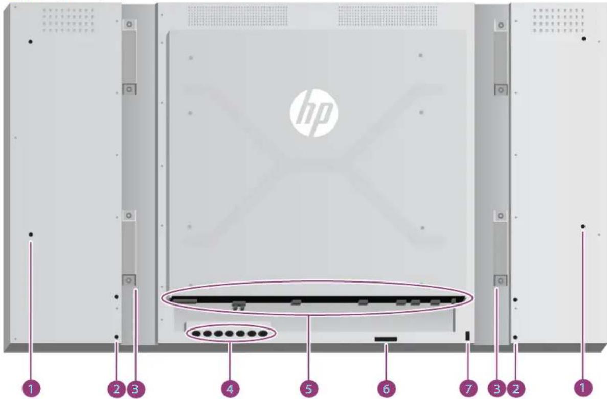
Table 3-1 Major components
| Component Function |
| 1 Speaker installation: 4 holes |
| 2 Stand installation: 4 holes |
| 3 Handles: 4 |
| 4 Control panel with power and OSD navigation buttons |
| 5 Power and data connectors |
| 6 Remote control sensor and ambient light sensor |
| 7 Security cable provision |
Connecting the speakers (sold separately)
- Mount the speakers onto the display.
Figure 3-2 Mounting the speakers
- Use the four Taptite D3 x 12 mm (0.47 in) screws to secure the speakers to the display.
Figure 3-3 Securing the speakers to the display
- After installing the speakers, connect to the SPEAKER input terminal by connecting the proper color match for the left and right speakers.
Figure 3-4 Connecting to the input terminal
Display control panel
This picture shows the controls on the back of the display. For details on using them, see Navigating with the control panel on page 38.
Figure 3-5 Controls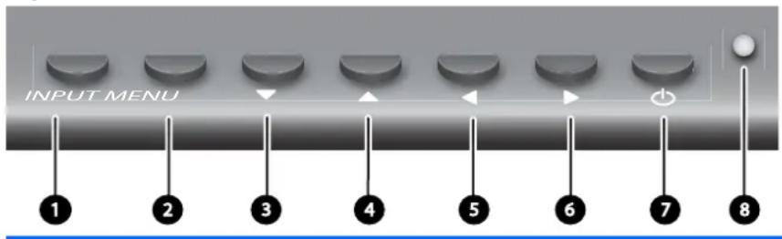
Control Label Function
1 INPUT Select video input source (VGA, DisplayPort, VOE) when not in OSD, Accept/Save a highlighted OSD choice when in OSD 2 MENU Invoke the On-Screen-Display Menu, Select highlighted entry, Exit OSD 3 ▼ Select/Adjust OSD choice, navigate down 4 ▲ Select/Adjust OSD choice, navigate up 5 ◀ Select/Adjust OSD choice, navigate left 6 ▶ Select/Adjust OSD choice, navigate right
7

Power display ON or OFF
8
Power status: Green → Full Power, Red → Stand-by mode, OFF → no power
Identifying remote control buttons
Figure 3-6 Remote control buttons
Label Function Description
| MUTE Sound mute Turns the sound on or off | ||
| Power on/off Turns the display on or off. | ||
| 1 - 9 Number Press once to enter a number. Press repeatedly to enter a letter. | ||
| 0 Zero or Space Press once to enter zero, second time to enter a space. | ||
| Period Decimal point or period. | ||
| Back or Delete Navigates backward, to the previous menu screen or delete text in text box. | ||
| DEL | ||
| INPUT Input Select video source (VGA, DisplayPort, VOE). | ||
| EXIT Exit Exits the on-screen menu. Unsaved changes will be lost. | ||
| ▲◀▶▼ | Up/down/left/right arrows | Allows navigation of the On-Screen Display menus and adjustment of the system settings |
| VOL - | Volume down (-) | Adjusts the speaker volume down (when not in OSD) |
| VOL + | Volume up (+) | Adjusts the speaker volume up (when not in OSD) |
| Label Function Description | ||
| ENTER Enter Accepts a highlighted selection or saves a setting. | ||
| INFO | Information | Invokes the Information option of the OSD menu. |
| MENU | Menu/Select | Invokes the On-Screen-Display main menu, invokes submenus within the OSD. |
| VGA | VGA input select | Selects VGA video input source for viewing. |
| PSM | Picture submenu | Invokes the Picture menu of the OSD. |
| VOE Video Over Ethernet input select | Selects VOE video input source for viewing. | |
| DP DisplayPort input select Selects DisplayPort video input source for viewing. | ||
| TILE | Tile mode | Opens the Tile Mode submenu of the OSD. |
| Color CAL | Color calibration | Launches the color calibration process. |
Setting up the remote control
Insert the batteries into the remote control as follows:
Figure 3-7 Inserting batteries
- Slide off the battery cover.
- Insert the batteries with correct polarity (+/-).
- Close the battery cover.

NOTE: To prevent environmental pollution, dispose of used batteries in accordance with your local recycling guidelines or see the Product Notices document provided on the media disc for proper battery disposal.
Mounting a single display on a stand (Sold Separately)
The stand kit is an optional accessory available from HP. It allows you to mount a single display in landscape position. To mount the display on the stand:
- Remove the four M4 x 32 mm (1.26 in) screws and stand from the box.
Figure 3-8 Stand accessory contents

- Place a soft cloth on the table and place the display with the screen facing downward. Connect the stand as shown in the following figure.
Figure 3-9 Securing the stand to the display
The long side of the foot should face forward when the screen is upright.
Installing the HP Frame System (Sold Separately)
The frame system creates a 10 mm border around one or more of the 47-in/119 cm displays, giving the edge a finished look. To frame a group of displays, you need as many kits as you have displays in a row or column, whichever is greater. For example, three kits will frame a 3 x 3 group, a 3 x 1 group, or a 1 x 3 group.
The frame kit includes four rails, one each for top, bottom, left and right. It also contains four interchangeable corner pieces and four interchangeable straight connectors.
The rails are labelled TOP for the top in landscape position, BOTTOM for the bottom in landscape position, RIGHT for your right side as you face the front of the screen, and LEFT for your left side as you face the front of the screen. All the screw holes match for the one rail that goes to each side; no force is needed. Attempting to attach the wrong rail could damage the bezel.
When you frame a single array, the numbers on the rails match at each corner:

To frame a single display, attach the top rail to the top of the display with three of the large (M4 x 10 mm) screws provided. The rail overlaps the bezel of the display. Attach the bottom, left, and right rails in the same manner, leaving the two small holes at each end open.
Figure 3-10 Attaching rails
Attach the four corner pieces with four small (M3 x 5 mm) screws each. These overlap the rails and secure their ends.
Figure 3-11 Attaching corners
Framing a group of displays is similar to framing a single display except that you will use some of the straight connectors to cover the gap between adjacent displays.
Figure 3-12 Framing an array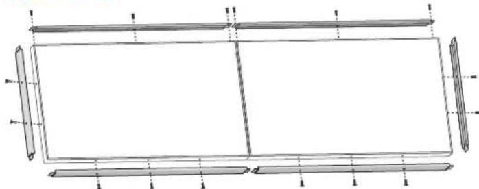
Attach corners and straight connectors after the rails are in place.
Figure 3-13 Attaching corners and connectors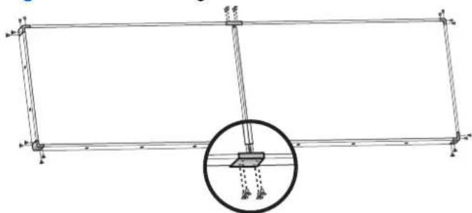
When you frame an array, the peripheral displays can no longer move independently. For this reason, the following tasks may best be done before framing:
• Color Calibration - Attaching all cables - Putting the main power switch in the ON (|) position • Horizontal, vertical and depth adjustment of all displays
Securing the display
Security cable provision—To help prevent theft, a security cable provision is available on the rear of the display. The cable and lock required to connect to the display are available separately and can be purchased from HP.
Figure 3-14 Cable lock
Connecting cables
Figure 3-15 Connectors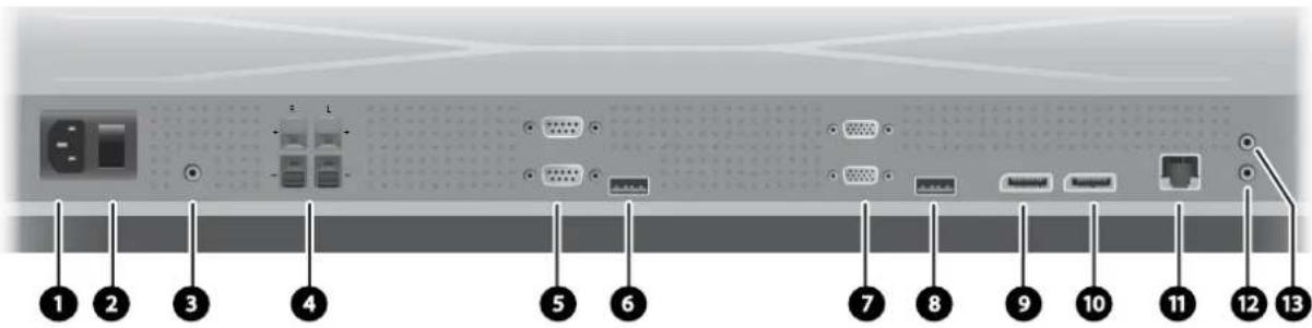
| Label | Function | |
| 1 AC-IN Receives the power cord. | ||
| 2 AC SWITCH Turns off or on power to entire device, controller as well as screen. | ||
| 3 LINE-IN For an audio cable connected to the Line Out on a media player or computer sound card. The plug should be a standard-sized, TRS-type with stereo capability. | ||
| 4 SPEAKER-OUT Audio output for bare-wire speaker connection to external speakers (sold separately). | ||
| 5 | RS232-OUT, RS232-IN | Serial port for control of the display. Takes a 9-pin, null-modem RS-232 cable connected to a controlling media player/computer or another digital signage display. |
| 6 USB For a color-calibration device or firmware upgrade. | ||
| 7 | VGA-OUT, VGA-IN | VGA input connects to a media player/computer or another display to support analog video and command data. VGA output supports chaining with VGA cables from display to display. The plug should be a 15-pin, D-Sub type. |
| 8 SERVICE PORT Used by authorized service personnel only. | ||
| 9 DP-IN DisplayPort input for digital video from a media player/computer. Connects to a media player/computer or another display in a chain. | ||
| 10 DP-OUT To connect to the DisplayPort input of another display in a chain. | ||
| 11 Ethernet RJ45 connector for video and command data from a network. Takes an Ethernet cable connected to a LAN or WAN; a network router, hub or switch; or directly to a media player/computer. | ||
| 12 | IR-IN | Infrared input for the external IR sensor (included) or the output from the previous display in a daisy chain (Blue Connector). |
| 13 | IR-OUT | Infrared output to connect to the next display in a daisy chain, for control of all displays with a single IR remote control (Green Connector). |
Follow these steps for connecting cables:
- Connect the AC power cord to the receptacle on the rear of the display (1).
Figure 3-16 Power
Read the power-cord safety precautions in Important safety information on page 3, then plug the other end into an electrical outlet.
Figure 3-17 Connecting the power cord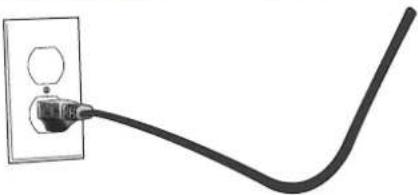
- Put the master power switch (2) into the ON (1) position.
Figure 3-18 Turn On Power Switch
- If you will be using the VGA input for video, and you want to play the audio feed through the external speakers, connect one end of an audio cable (sold separately) to the Audio input jack (3) and the other end to the Line Out jack on the media player/computer.

NOTE: Before connecting to the AUDIO port on the display, verify what type of Audio Out connection is available on the media player/computer sound card. The Line Out on a media player/computer is used to connect to speakers, including a built-in amplifier (AMP). For additional instructions, refer to the sound card manual.
If the Audio Out on the media player/computer sound card has only Speaker Out, reduce the media player/computer volume before connecting to the AUDIO port on the display.
If the Audio Out on the media player/computer sound card supports both Speaker Out and Line Out, choose Line Out.
Figure 3-19 Audio connection

NOTE: The ferrite core can be used to reduce electromagnetic waves when connecting an audio cable. Fit the ferrite core to the audio cable. The ferrite core needs to be separated from the mold by 5 cm (2 in).
Figure 3-20 Using the ferrite core
- If you will be employing the HP external speakers, the bare speaker wire should be connected to the matching color coded speaker connector for the Right and Left speaker, as in Connecting the speakers (sold separately) on page 8.
Figure 3-21 External speaker connections
- If you want to remotely control and manage the display with the RS-232 Serial interface, attach one end of an RS-232 cable to the RS-232 input (5) port (With the display lying on its face, the input port is below the output port) and connect the other end to the serial interface port of the media player/computer.
If you will be connecting more displays in a series (daisy chain), connect one end of a second RS-232 cable to the output (upper) port of the display and the other end of the RS-232 cable to the input port of the next display in the chain. (See Connecting multiple displays to one player on page 24 for more details).
Figure 3-22 RS-232
- The USB port is for attaching a color-calibration device such as the HP DreamColor Display Calibration Solution and is also used in the event of a firmware upgrade. Neither USB device is plugged in until the time of use. However, if access to the USB port (6) will be limited once the display is mounted, you can attach a USB extension cable now.
Figure 3-23 USB
- If you will be using analog video, plug the VGA cable into the VGA input connector (7). Since the VGA connection does not transmit audio, you may need to connect an audio cable as described in Step 1 (input is the lower of the two VGA connectors with the display on its face) and plug the other end of the VGA cable into the VGA adaptor on the media player/computer.
If you will be connecting this display to another display via VGA (daisy chain), plug one end of a second VGA cable into the Output (upper) VGA connector (7) on the display and plug the other end of the VGA cable into the Input (lower) VGA connector of the next display in the chain. (See Connecting multiple displays to one player on page 24 for more details.)
Figure 3-24 VGA connection
Plug the free end of the VGA cable into a media player/computer or the previous display in a chain of displays.
- If you want to send video over the DisplayPort, connect the DisplayPort cable to the DP IN port on the display (9) and connect the other end of the DisplayPort cable to the DisplayPort adaptor of the media player/computer.
If you will be connecting this display to another display via DisplayPort (daisy chain), plug one end of a second DisplayPort cable into the DP-Out connector (10) on the display and plug the other end of the DisplayPort cable into the DP-IN connector of the next display in the chain. (See Connecting multiple displays to one player on page 24 for more details.)
Figure 3-25 DisplayPort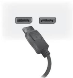
Connect the free end of the DisplayPort cable to the DisplayPort OUT port on the media player/computer or previous display in a series.

NOTE: Since DisplayPort does not support RS-232 command data, you will also need to connect either an RS-232 cable between the display and media player/computer or an Ethernet connection to the network or media player/computer to use HP Network Sign Manager to manage and control the display remotely.
- If you will be connecting the display to a network, plug your CAT-5 network cable into the Ethernet port (11).
Figure 3-26 Ethernet
The Ethernet cable from the display can connect to a media player/computer, a router (switch), or an Intranet. A network connection enables the use of the Video Over Ethernet software to assign a media player to drive the display. The connection also allows the HP Network Sign Manager program, running on a networked media player/computer, to send command data.
Connect the Ethernet cable (not included) using one of the following connections:
- Computer Direct Connection—Connect the LAN cable to the LAN port on the display and to the LAN port on the media player/computer (1).
- Router—Connect the LAN cable to the LAN port on the display and to a LAN port on the router (2).
- Intranet—Connect the LAN cable to the LAN port on the display and to the Intranet network via an access point (3).
Figure 3-27 Connecting the Ethernet cable![graph TD A["1 LAN"] --> B["2 LAN"] B --> C["3 LAN"] style A fill:#f9f,stroke:#333 style B fill:#ccf,stroke:#333 style C fill:#cfc,stroke:#333](/content/2026/06/1381292/images/be21419ab31d8b89c02989600f038944c2ed3c17361275ed9dd1ec1c2e61e7bc.jpg)
- If you want to use the external IR sensor, plug it into the IR-IN jack (12). The external sensor makes using the remote easier, especially with displays mounted in a video wall.
Figure 3-28 Infrared sensor connection
Place the IR sensor facing where you want the remote to be.
- If you want to connect this display to another in an IR daisy chain, plug the included IR Daisy Chain cable into the IR-OUT jack (13). The free end will plug into the IR-IN of the next display in the chain.
Figure 3-29 IR-OUT connection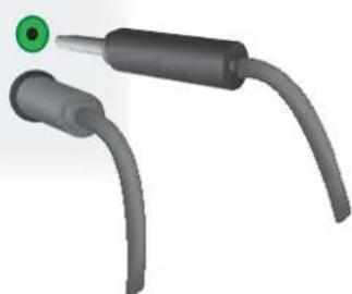
Connecting multiple displays to one player
Multiple displays may be connected to a single media player/computer two different ways, using Video Over Ethernet or using Tile Mode with VGA or DisplayPort video inputs.
Connecting multiple displays with Video Over Ethernet (VOE)
To connect multiple displays to a single media player/computer, each display must be connected to the same network as the media player/computer. The input source of each display must be set to VOE. With VOE, displays are connected to media players/computer by establishing an Association between the media player/computer and one or more displays on the network with the VOE software that runs in the media player/computer. Up to 12 displays may be associated with a single media player/computer (See the VOE Users Guide for more detail). When multiple displays are associated with a single media player/computer, the displays may be mirrored (a single desktop image displays on all the displays simultaneously).
Figure 3-30 Mirrored displays![graph TD A["Client 1"] -->|CATs| B["Ethernet LAN/WAN"] C["Client 2"] -->|CATs| B D["Client 3"] -->|CATs| B E["Client 4"] -->|CATs| B B --> F["Server"] style B fill:#f9f,stroke:#333](/content/2026/06/1381292/images/5ea310400a85a17eb55407cf757543cdbf235ab3667905e9ace297985abed137.jpg)
The image may be extended across all the displays simultaneously using the View Span "Display Resolution" dialog box.
Figure 3-31 Extended desktop![graph TD A["Server"] --> B["Ethernet LAN/WAN"] B --> C["Router"] style A fill:#f9f,stroke:#333 style B fill:#ccf,stroke:#333 style C fill:#cff,stroke:#333](/content/2026/06/1381292/images/3f943fcc9f2fec1a8136105bd8fbc6716be1599acaf72374b2fc243b8bd229d7.jpg)
The displays may be treated by an application as though there were up to 12 individual displays connected to 12 graphic adaptor heads on the media player/computer.
Figure 3-32 Multiple independent displays![graph TD A["Ethernet LAN/WAN"] --> B["Server"] style A fill:#f9f9f9,stroke:#333 style B fill:#e6f7ff,stroke:#333](/content/2026/06/1381292/images/21c33d8630ae5c88ea36c04b47490c54c16cbb42faf8d6e316278aa73ac12a01.jpg)
The association of up to 12 displays is the technical limit, and depending upon the complexity of the desktop image to be displayed (playing flash, or streaming video), the number of displays which can be associated with acceptable video performance may be less than 12 (See the Video Over Ethernet User Guide for more detail).
Connecting multiple displays with Tile Mode
The recommended cable routing for daisy chain in Tile Mode is to start with the upper left display and connect across the upper tier of displays going from left to right to the last display in that tier. Then cable from the upper right display to the display just below it and connect across from right to left to the last display on the left. Continue this back and forth, top to bottom cable route for all the tiers in the wall as indicated in the next figure.
Figure 3-33 Recommended cable routing for Tile Mode![graph TD Start --> A1["Start"] Start --> A2["Start"] Start --> A3["Start"] Start --> A4["Start"] Start --> A5["Start"] Start --> A6["Start"] Start --> A7["Start"] Start --> A8["Start"] Start --> A9["Start"] Start --> A10["Start"] Start --> A11["Start"] Start --> A12["Start"] Start --> A13["Start"] S…](/content/2026/06/1381292/images/89ac8817c92d4ccdab3ab4ce89b6134da36a0410882bb6ec27dcbb4223bdc2e6.jpg)
Multiple displays (up to 25) may be connected to a single media player/computer using Tile Mode. Multiple displays in Tile Mode are only supported with either DisplayPort or VGA video input sources. When connecting the multiple displays, the media player/computer is connected to the first display only with either a DisplayPort or VGA connection to the media player/computer. All the subsequent displays are connected to each other via daisy chain using either the DP OUT connector from one display to the DP IN connector of the next display (Figure 3-35 Daisy chain connection - DisplayPort on page 27), or using the VGA OUT connector from one display to the VGA IN connector of the next display (Figure 3-36 Daisy chain connection - VGA on page 27). All displays must be connected with the same video source, either DisplayPort or VGA. When using Tile mode to connect multiple displays, only one desktop image may be displayed across all the tiled displays
Figure 3-34 Multiple displays with tile mode
Figure 3-35 Daisy chain connection – DisplayPort![graph TD A["Server"] --> B["Data Unit"] B --> C["Processing Unit 1"] C --> D["Processing Unit 2"] D --> E["Processing Unit 3"] E --> F["Output"] style A fill:#f9f,stroke:#333 style F fill:#bbf,stroke:#333](/content/2026/06/1381292/images/727075549cdde7f401ec0bed062dfc0a277bcde343c94b0678c87ac0a883cca5.jpg)
Figure 3-36 Daisy chain connection - VGA![graph LR A["Input Device"] --> B["Processing Unit 1"] B --> C["Processing Unit 2"] C --> D["Processing Unit 3"] D --> E["Processing Unit 4"] E --> F["Output Module"] style A fill:#f9f,stroke:#333 style F fill:#bbf,stroke:#333](/content/2026/06/1381292/images/4ca69dc649c4489c30a1bb43402a1b1b0dc61bf9725e9066f03eaf5a8599540e.jpg)
To remotely manage and control multiple displays in Tile Mode when using either VGA or DisplayPort video source, either a RS-232 or Network connection may be used with the HP Network Sign Manager.
If using the RS-232 interface, the displays must be daisy chained with RS-232 cables. Attach one end of a RS-232 cable to the RS-232 Input connector of the first display and connect to the serial connector of the media player/computer. Then attach one end of an RS-232 cable to the RS-232 Output connector and the other end to the RS-232 Input connector of the next display and continue to connect the RS-232 cables between each display in the tiled matrix as shown in Figure 3-37 Daisy chain connection – RS232-C on page 28.
If using a Network connection, just attach each display to a network hub or access point using a CAT-5 cable, and HP Network Sign Manager will locate each network attached display. The HP Network Sign Manager will allow users to select any display or assigned group of displays to manage and control. If the display is already attached to the network for VOE, there is no further action required. The HP Network Sign Manager will detect the displays via its search function (See the HP Network Sign Manager Users Guide for more details).
Figure 3-37 Daisy chain connection – RS232-C![graph LR A["Server"] --> B["RS-232C (CONTROL)"] B --> C["Port 1"] B --> D["Port 2"] B --> E["Port 3"] B --> F["Port 4"] B --> G["Port 5"] B --> H["Port 6"] B --> I["Port 7"] B --> J["Port 8"] B --> K["Port 9"] B --> L["Port 10"] B --> M["Port 11"] B --> N["Port 12"] B --> O["Port 13"] B --> P["Port…](/content/2026/06/1381292/images/01752d450f9edd08a1a38ad0fad23d670f2695550b42808b04e3a8463a7a479a.jpg)
Multiple displays may also be controlled and managed with the IR Remote Control. Since the primary use of the displays is for video walls, use of the External IR Sensor is needed to provide the best IR remote control responsiveness. Connect the supplied External IR Sensor to the IR IN (Blue) jack. Take one end of the supplied IR Daisy Chain Cable and connect it to the IR OUT (Green) jack of the display and connect the other end of the cable to the IR IN jack of the next display as shown in Figure 3-38 Daisy chain connection – External IR Sensor on page 28. Once all the displays are connected, the user can issue any OSD command with the IR Remote Control to all the displays at once (for example, turn the displays ON or OFF, set Picture Mode to VIVID, etc.), or the user can indicate a single display in the wall to control by selecting the ID of the appropriate display and then issuing any OSD command with the IR Remote Control. See Navigating with the infrared remote control on page 37 for more detail.
Figure 3-38 Daisy chain connection – External IR Sensor

NOTE: The number of displays that can be connected by daisy chain to one media player/computer might vary depending on the signal status and cable loss. If the signal status is good, and there is no cable loss, it is possible to connect up to twenty-five displays in a daisy chain from one media player/computer.
If you are going to play video that is copy protected with High-bandwidth Digital Content Protection (HDCP), you must use DisplayPort as the video source, and you are limited to a maximum of six displays in the daisy chain which can support HDCP.
When using Tile Mode, the display ID can be set in the display OSD with the IR Remote Control, the display control panel, or for Network attached displays, the display ID can be set with the HP Network
Sign Manager software (See Using Tile Mode on page 49 and the HP Network Sign Manager User Guide for more details).
After installing the cables, ensure that the power switch on all displays is in the on position (1). Turning the Power Switch ON does not turn the display on. This is especially important if you will be mounting the displays where access to the power switches is difficult.
Figure 3-39 Turn On Power Switch
The last step, after all the cables are connected and making sure the Power Switch is turned ON, is to plug the AC power cord into a power source.
Mounting the display
The display can be mounted on a wall or a stand. If the mounting hardware permits, it can be mounted in landscape or portrait orientation.

CAUTION: Always use the handles to lift the display, as the bezel is not meant to take its weight.
CAUTION: Two people are needed to safely mount the display.
This product supports a VESA FDMI (Video Electronics Standards Association Flat Display Mounting Interface)-compliant mounting device. The mounting devices can be purchased separately from HP. Two hole patterns are available, holes on 400 mm centers (1) and holes at 400 mm x 200 mm (2).
Figure 3-40 VESA mounting holes
It is recommended that the 400 mm x 400 mm mounting pattern be used whenever possible.
The distances of each hole to the edges of the display are shown in Technical specifications on page 63. The weight for your model can be found there as well; when mounting to a wall, ensure that the supporting structure is strong enough for the listed weight.
Mounting in portrait position
When installing the display in the portrait position, rotate it clockwise based on its front. The display can be rotated in only one direction. Arrows on the back of the display indicate which side should be at the top in both portrait and landscape positions:
Figure 3-41 Up arrows
Figure 3-42 Installing portrait![graph TD A["Rectangle"] --> B["Blank Rectangle"] A -->|Arrow Down| A A -->|Arrow Up| A](/content/2026/06/1381292/images/1514706a2b6f89e2f881ef277924fbf7b11c33802c860c0abda9b204f01a22c2.jpg)
The cable connectors will be on your left as you face the screen.
Considerations for wall mounting
When mounting displays in a video wall consider the following:
- If all the displays are on one electrical circuit, you can avoid overload at power up by using the Power On Delay option in the OSD menu (Option 2 → Time → Power On Delay).
- Care should be taken to make sure that the displays are mounted so that they are just touching and that there is no load bearing pressure between displays.
- If access to the back of the display will be difficult, you can attach all cables to each display before installation on the wall mount and turn the main power switch ON (|) before placing the display flush against the wall. You can perform any desired color calibration before mounting, or you can install a USB extension cable in the USB port to facilitate color calibration in the future.
- If you will be installing the HP Framing System, do so after all displays have been mounted and adjusted.
Software and utilities
HP displays are Plug-and-Play with Microsoft Windows operating systems, so you do not need to install the .INF file or the .ICM file for these operating systems. Software, utilities and documentation are provided on the disc that comes with the display. The most current versions of the following software and utilities can be downloaded from the following HP website for use with the displays as needed: www.hp.com.
• Display driver firmware • Auto-adjustment Pattern Utility — Optimizes the display of VGA input. • Supporting system files, .INF and .ICM HP Network Sign Manager — Remote management and control software. Allows you to select and control displays singly or in groups, remotely from a media player/computer connected by RS-232 or Ethernet. - Video Over Ethernet — Software that runs on the media player/computer which lets you discover network connected displays, associate displays to any media player/computer attached to the network, and send video from the media player/computer to the associated display.
You can also install any of these from the disc that comes with the display.
The information file
The setup information, or .INF file, defines display resources used by Microsoft® Windows operating systems to ensure display compatibility with the media player/computer's graphics adapter.
The image color matching file
The image color matching, or .ICM file, is a color data file that is used in conjunction with graphics applications to provide consistent color matching from display screen to printer, or from scanner to the display screen. The .ICM file is only activated from within the graphics applications that support this feature.
Installing the driver, .INF and .ICM files
The display driver firmware and the supporting system files are packaged together and installed with one download operation.
You can install the .INF and .ICM files from the disc or download them from the HP displays support website.
Installing from the disc
To install the .INF and .ICM files on the media player/computer from the disc:
- Insert the disc in the media player/computer CD-ROM drive. The disc menu appears.
- View the Display Driver Readme file.
- Select Install display driver software.
- Follow the on-screen instructions.
- Ensure that the proper resolution and refresh rates appear in the Windows Display control panel.

NOTE: You might need to install the digitally signed display .INF and .ICM files manually from the disc in the event of an installation error. Refer to the Display Driver Readme file on the disc for instructions (in English only).
Downloading from the Web
To download the latest version of .INF and .ICM files from the HP displays support website:
- Refer to www.hp.com/support and select the country/region.
- Follow the links for the display to the support page and download page.
- Ensure the system meets the requirements.
- Download the software by following the instructions.
Installing management software
Two programs are provided to manage displays. Video Over Ethernet allows you to assign media players on a network to displays on the same network. The HP Network Sign Manager provides remote management and control of digital signage displays. You can select and control individual displays, or you can group displays so that commands will control multiple displays simultaneously.
Install these programs from the disc, if a disc is provided with your display, by choosing the installation option from the menu that appears when you insert the disc into the media player/computer on which you want to run the software and then following the instructions. Alternatively, you can download the programs from www.hp.com/support and then install from the downloaded package.
For details on using the applications, refer to the HP Network Sign Manager User Guide and the Video Over Ethernet User Guide (both available only in English) included on the disc provided with the display.
4 Operating the display
The display can be operated with the infrared remote control, with the control panel buttons, or remotely by any network connected media player/computer using HP Network Sign Manager. The media player/computer running HP Network Sign Manager can be connected to the display directly with an Ethernet peer to peer connection or RS-232-C serial connection, or remotely via an intranet connection.
Operation with the remote or the control panel uses the On-Screen Display (OSD) menu. This chapter details the menu.
The display provides for more than one source of video input. It will scan the various inputs to find an active one and display that image. The default scan order is Video Over Ethernet, DisplayPort, VGA for any inputs that are connected to a video source. Using the OSD menu, you can prevent the display from switching inputs by disabling this function.
In order to send video over a network, you need to install the VOE software on the computer/media player which serves as the source. See the Video Over Ethernet User Guide for details.
If the display is not receiving any input, it will go into low power mode ("sleep"). You can send it into low-power mode using the power button on the back, the infrared remote control, or by scheduling sleep times. Scheduling is done through the OSD or management software. You can also prevent the display from sleeping.
Using the On-Screen Display menu
The on-screen display menu (OSD) lets you set a variety of parameters to control the display. Not all settings are applicable to all video sources and these will be greyed out (unselectable) where they don't apply. Auto Configuration, Clock Frequency, and Clock Phase apply only to VGA input.
Other settings store three values, one each for Video Over Ethernet, VGA and DisplayPort. These settings are:
Picture Mode - Contrast - Brightness Sharpness Backlight
Resolution • Color Temperature Speaker Aspect Ratio
All other OSD settings need only be set once in order for the new value to apply regardless of the video source.
You can operate the OSD using the infrared remote control or the control panel on the back of the display.
Controlling displays with IR Daisy Chain
The display provides the capability of using IR Daisy Chain to enable selectable control of the displays locally, using the IR Remote Control when the displays are mounted in a video wall. You may control one display at a time by selecting the ID of the display, or you may control all the displays simultaneously by selecting an ID of "00".
Setting up IR Daisy Chain
The following describes how to set up the displays for IR Daisy Chain
- Insert the External IR Sensor into the IR IN (blue) jack at the back of the display
- Using the included IR Daisy Chain Cable, connect all the displays in the video wall. See Connecting cables on page 15 for details.
- Using the IR Remote Control or the display control buttons, go to MENU → OPTION 2 → SET MONITOR ID and set the unique ID number (number between 1 and 25) for each display in the video wall
- Using the IR Remote Control or the display control buttons, go to MENU → OPTION 2 → IR OUT and chose ENABLE for each of the displays in the video wall
- Using the double sided tape, locate the External IR Sensor away in a spot where it will be easy to point the IR Remote Control. It is recommended that the sensor be located at the top left or right of the video wall.

NOTE: Care should be taken to avoid locating the sensor next to the bottom of any of the displays where the IR sensor of the display could sense the IR Remote Control or where the sensor might block the viewing area of any display.
Controlling displays with the IR remote control
Point the IR remote control at the External IR Sensor and press the MENU button. The IR Daisy Chain home menu will appear on each display, with the Monitor ID displayed so you can easily identify the
Display you want to issue the command to (Figure 4-1 IR Daisy Chain home menu screen on page 36).
Figure 4-1 IR Daisy Chain home menu screen
| Menu | Setting | Function |
| A Monitor ID ID number assigned to the display in the SET MONITOR ID Dialog | ||
| B IR Daisy Chain Monitor ID Enter the ID number of the display you want to receive the IR commands or enter "00" to control all the displays simultaneously | ||
| C Set Button Sets the display ID of the display you want to control and will lock out all the other displays from receiving the commands | ||
| D Exit Button Exit the IR Daisy Chain dialog without setting the display ID to receive commands | ||
Enter the ID number of the display in the two-digit window (following figure). Entering "00" in this window will allow all the displays in the daisy chain to receive the command. This may be useful when turning the displays ON or OFF, or setting the time schedule for the video wall.
Figure 4-2 Identify the display to control
Press the SET button to select the display ID number as the display you want to send commands. The LOCK message window will appear in all the other displays to indicate that they will not receive any commands from the IR remote control through the External IR Sensor (Figure 4-3 IR Lock Message on page 37). The On-Screen Display Menu will appear in the display selected. Any command, menu selection, or setting entered with the IR remote control will now be executed by the selected display.
Figure 4-3 IR Lock Message
After a short period of time, the Lock message will disappear from the displays. At any time, you may press the INFO button on the IR remote control and the Lock message will reappear on the displays not selected to receive the IR commands:
Figure 4-4 Lock message from INFO command
Pressing the MENU key on the IR remote control will exit the IR daisy chain mode and unlock all the displays.
Navigating with the infrared remote control
The IR sensor is on the back of the display but will receive IR signals coming from the front. Point the remote control toward the bottom center of the screen. You can also use the external sensor provided, which makes the remote control very easy to use. This is especially true for displays in a video wall. If you have connected multiple displays with IR daisy chain, they will all respond to a key press of the remote. See Controlling displays with IR Daisy Chain on page 35 for more details.
See Identifying remote control buttons on page 10 for details on IR remote control buttons and their functions.
Navigating with the control panel
If you have access to the control panel at the back of the display, you can use it to turn the screen on and off, and to open and navigate the OSD menu.
Figure 4-5 Display control panel
To change the video source, press the INPUT button, then select the desired source from the menu that opens on the screen.
To bring up the On-Screen Display menu, press the MENU button. Press it again to exit the OSD.
Once inside the menu,
• Use the arrow buttons to highlight your choice. Use them to adjust settings as well. • To accept a highlighted selection or setting, press the INPUT button.
To put the display into low power mode, press the power (⏻) button. Press it again to restore full power.
The buttons can be disabled by pressing the left and right arrows buttons simultaneously and holding for 5 seconds. Repeat this procedure to enable the buttons again.
Single buttons can be disabled and enabled with the following 5-second key presses:
To enable/disable this: Hold these buttons:
| Power button Right arrow and MENU buttons |
| IR remote control Left arrow and MENU buttons |
| MENU button Up and down arrows. |
The LED indicates the power status:
- Green — full power
- Red — low power (the screen is dark but the controller is listening for commands)
- Off — no power
If the buttons remain untouched for 20 seconds after adjustments have been made but not saved, the current settings will be saved and the OSD menu will close. If the input source, resolution, aspect ratio or frequency changes while the OSD is active, the OSD will close without saving new settings.
OSD menu selections
The OSD menu contains six main menus:
Icon Menu Function description
 | Picture | Set or change video characteristics such as, brightness, contrast, and resolution. |
 | Audio Set or change the audio options. | |
 | Option 1 | Set or change display options such as video source, aspect ratio, and network settings. |
 | Option 2 | Set or change display options such as OSD language, schedule, and ISM method. |
 | Color Calibration Launch the color calibration process. | |
 | Tile Mode Set or change the tiling options when this display is one of an array. | |
The following table lists the On-Screen Display (OSD) menu selections and their functional descriptions. Not all options apply to all types of input. For example, clock adjustment is only applicable to VGA input.
Level 1 Menu Level 2 Menu Level 3 Menu Description
| Picture | Picture Mode | The three preset modes set the picture submenu options for the following: |
 | Vivid — For standard video.Standard — For viewing images.Cinema — For movies.If you prefer to set the picture submenu options yourself, you will automatically switch to Expert 1The default setting is Standard. |
Level 1 Menu Level 2 Menu Level 3 Menu Description
| Contrast | Increase or decrease the difference between the light and dark colors. |
| Adjustable scale, 0 – 100 with 100 being high contrast. | |
| The default setting is 50. | |
| Brightness | 0 – 100 scales adjusts the brightness of the screen. |
| The default setting is 50. | |
| Sharpness | 0 – 10 scale makes the image crisper or softer. When you change this setting, the change will show immediately so that you can judge where you want it to be. |
| The default setting is 5. |
Backlight Controls the brightness of the backlight, 0 - 100.
| The default setting is 90. | ||
| Dynamic | Contrast | On — Allows the display to adjust the backlight for better contrast, depending on the image.Off — Does not allow the display to change the backlight level depending on the image.The default setting is OFF. |
| Resolution | Auto — allows the display to choose any supported resolution that matches the input signal. 1280 × 768 pixels 1360 × 768 pixels 1366 × 768 pixelsThe default setting is Auto. | |
| Color | Temperature | Adjust the shade of white the display produces. 9300 K — Slightly purplish white. 8000 K — Slightly bluish white 6500 K — Standard paper-white.User · Set the R, G, B gain values yourselfThe default setting is 9300. |
| Level 1 Menu Level 2 Menu Level 3 Menu Description | ||
| Energy Saving | Select from the following backlight brightness levels:Off—100% lightLevel 1—80% lightLevel 2—60% lightLevel 3—40% lightThe default setting is Off. | |
| Audio | Volume Adjust the volume from 0 to 100. | |
 | The default setting is 50. | |
| Speaker | On—Play sound through the attached speakers.Off—Turn off attached speakers in order to use an external sound system.The default setting is On. | |
| Audio Source | Line-in—With analog video, choose this option to play sound from the audio input at the back of the display.DisplayPort—With digital video, choose this option to play the sound accompanying the video.VOE—With VOE for video, choose VOE for sound as well.The default setting is VOE. | |
| Balance | Balances sound between the left and right speakers.The default setting is 50; range is 0–100, with 0 being all sound from the left speaker. | |
| Treble | Adjust treble 0–100. | The default setting is 50. |
| Bass | Adjust bass | 0–100.The default setting is 50. |
| Sound Mode | Standard—Most natural audio.Voice—Differentiates the human sound range from other sounds, which helps to make the human voices easier to hear.The default setting is Standard. | |
Level 1 Menu Level 2 Menu Level 3 Menu Description
| Option 1 | Aspect Ratio | Select from the following image proportions: | |
 | 16:9 — Widescreen mode.1:1 — Picture format is 1:1 aspect ratio.Original — Picture format is automatically set to 16:9 or 4:3 aspect ratio according to input signal.4:3 — Picture format is 4:3 aspect ratio.14:9 — Programs are viewed normally in 14:9 with black bars added to the top and bottom. If the input is 4:3, it will be stretched horizontally.Zoom — 4:3 programs are magnified until they fill the 16:9 screen. The top and bottom will be cut off.Cinema Zoom — Picture format is 2.35:1 aspect ratio, extending the picture horizontally with black bars added to the top and bottom.The default setting is 16:9. | ||
| Source | Select | video | source:VGA — Analog video through the VGA port.DisplayPort — Digital video through the DisplayPortVOE — Digital video through the Ethernet portThe default setting is VOE. |
| Auto | Configuration | Automatically adjusts picture position and minimizes image instability (VGA input only) | |
| Clock | Frequency | Adjusts the controller's clock frequency from 0 to Dynamic. SeeOptimizing analog images on page 51for details. | |
| Phase | Adjusts the controller's clock phase from 0 to Dynamic. SeeOptimizing analog images on page 51for details. | ||
| H.Position | Adjustable scale, 0 to 100, moves the image right or left on the screen. | ||
| V.Position | Adjustable scale, 0 to 100, moves the image up or down on the screen. | ||
| Ambient Light Sensor | High — Frequently adjust the backlight based on input from the sensor.Low — Periodically adjust the backlight based on input from the sensor.Off — Do not adjust the backlight based on input from the sensor.The default setting is Off. | ||
| Level 1 Menu Level 2 Menu Level 3 Menu Description | |
| Interface Select | If the display will be controlled by software on a media player/computer, select the type of cable connecting it to that media player/computer:RS232 — for RS-232 cable.Network — for Ethernet cable.The default setting is Network. |
| Auto Detection | On — Allows the display to automatically detect a signal on any input source and show the image.Off — Video source must be selected manually.The default setting is On. |
| NSM Network | If the display is controlled by software on a networked media player/computer, it needs settings that tell the media player/computer where to send command data:DHCP Dynamic Host Configuration ProtocolEnable — Allows the network host computer to assign an IP Address to the display when it comes on line.Disable — Allows you to assign a permanent IP Address and Subnet Mask.The default setting is Enable. |
| IP Address | The Internet Protocol address needed for a network connection.The default is 192.168.0.1 |
| Subnet Mask | A number specific to your network used in conjunction with the IP address.The default is 255.255.255.0 |
| WOL Wake-up On Low powerEnable - Management software can change the display from low power ("sleep") to full power.Disable - Management software cannot change the display from low power to full power.The default setting is Disable | |
| Security PIN Protects the NSM network commands.The default is 000000.When the PIN is changed, the Lock and Unlock NSM commands are enabled. The display will be automatically locked after 10 minutes of no network command activity. | |
| VOE Network | If the display receives video data from a networked media player/computer, it needs settings that tell the media player/computer where to send video data: |
Level 1 Menu Level 2 Menu Level 3 Menu Description
| DHCP Dynamic Host Configuration ProtocolEnable — Allows the network host computer to assign an IP Address to the display when it comes on line.Disable — Allows you to assign a permanent IP Address and Subnet Mask.The default setting is Enable. | ||
| IP Address | The Internet Protocol address needed for a network connection.The default is 192.168.0.2 | |
| Subnet Mask | A number specific to your network used in conjunction with the IP address.The default is 255.255.255.0 | |
| VOE Setup | These fields are recognized by the Video Over Ethernet software.Display Name — Give this display a name up to 32 alphanumeric characters long for reference through the VOE software.Display Location — Identify this display's physical location in a way meaningful to you. Use up to 32 alphanumeric characters.Product Name — Automatically shows display model name.Player Name — The computer name of a computer/media player running VOE software whose output is to be played on this display. You can enter such a name. The VOE software will enter a name when it assigns a video source to this display. | |
| Option 2 | Language | Selects the language in which the OSD menu is displayed.The default setting is English. |
 | ||
| OSD Mode | Set the OSD orientation to match the display's orientation, portrait or landscape.The default setting is landscape. | |
| Level 1 Menu Level 2 Menu Level 3 Menu Description | ||
| TIME | ClockSet the current date and time so that scheduled events happen at the correct time.Year: 2000 – 2099Month: 1 – 12Day: 1 – 31Hour: 0 – 23Minute: 0 – 59Daylight saving time: ON/OFFThe default setting is Off. | |
| ScheduleYou can schedule up to 7 On/Off times for the display to enter low power mode (screen is dark) or come out of low power to full power:On — Set a time for the display to turn on full power.Off — Set a time for display to “sleep.”Input — Choose the input source to play at the ON time.Select the frequency for this event:Every Day — Play this event every day at the scheduled time.Monday – Sunday choices: Play this event on the selected days.Every Week — If checked, the event will play on the selected days every week. If not checked, the event will play on the selected days for one week only. | ||
| DelayPower On to stagger the power-up of multiple displays on an electrical circuit, turn this option on. Each display will choose a delay either randomly or based on its tiling number.No — No delay on power up.The default setting is No. | ||
| DPM Select Display Power Management Select | ||
| Wake On All — The display will enter low power mode when there is no signal on the VGA and DP inputs.Disable Sleep — Prevents the display from entering low-power mode.Wake on VGA — Equivalent to On when Auto Detect is on. When Auto Detect is off, will enter low power mode when VGA is the selected video source and there is no signal on the VGA input, but will not enter low power mode when another source is selected.The default setting is Wake on VGA. | ||
Level 1 Menu Level 2 Menu Level 3 Menu Description
| Key Lock | On – Disable the buttons at the back of the display.Off — Enable the buttons at the back of the display.The default setting is Off. |
| Set Monitor ID | Assign a unique, two-digit number between 01 and 25 to this display. You will see this number if you have daisy chained the IR ports of several displays. HP Network Sign Manager also uses it to communicate directly with the display.The default setting is 01. |
| ISM Method | To prevent the screen from retaining an image that remains static for a long period of time, choose one of these relief methods:Orbiter— The image moves two pixels every two minutes. Direction of movement is right, left, up, and then down, in a continuous cycle.Inversion — Inverts the colors every 30 minutes. This function can be used to fix a ghost or burned-in image.White wash— Fills the screen with white. This function can be used to fix a ghost or burned-in image. Press any key on the remote control to exit the White Wash function and return the screen to normal.Dot wash— Imposes black dots on the image, moving them every 5 seconds.OFF — No remedy for image retention will be used.The default setting is Off. |
| DDC/CI | On — Allows an attached media player/computer to send control commands to the display.Off — Control of the display must be done manually, with the infrared remote control or the buttons on the back of the display.The default setting is On. |
| Factory Reset | Resets all OSD choices to their default factory settings.User modes will be erased from memory. |
| Diagnostic Shows the following information: | Temperature in degrees CentigradeAmbient light level in LuxLED Failure: Yes/NoOperating time in hours |
| Level 1 Menu Level 2 Menu Level 3 Menu Description | ||
| Information Shows the following: | ||
| Serial numberSW Version (MNT) — The version of the firmware driver running on the display.IP Address (VOE) — The IP Address of the network connection handling video data to the display.MAC Address (VOE) — The Media Access Control address of the network connection handling video data to the display.IP Address (NSM) — The IP Address of the network connection handling control data to the display.MAC Address (NSM) — The Media Access Control address of the network connection handling control data to the display. | ||
| IR out | Enable — Enable the external IR receiver and IR daisy-chain support.Disable — Disable the external IR receiver and IR daisy-chain support.The default setting is Disable. | |
| Firmware | Update | Current Ver. — Shows the version number of firmware currently running on the display.Detected Ver. — Shows the version number of firmware detected on a USB device plugged into the display.Yes/No — Choose yes to upgrade firmware on this display. |
Color Calibration  | Color Calibration | Enter — Enter the color calibration process.Restore Factory Cal. — Restores the factory calibration settings.Restore Last Cal. — Restores the last calibration settings.Exit — Exit without calibrating color.See Tuning color on page 52 for details of the color calibration process. |
| Result | When calibration is complete, the display measures the following parameters with the new correction:LuminanceColor TemperatureGammaR, G, and B coordinates in CIE X,Y color spaceThe number of hours since calibration is also shown. If the display has never been calibrated, that fact is shown. | |
Level 1 Menu Level 2 Menu Level 3 Menu Description
| Tile Mode | H Monitors | Enter the number of displays in a row of your array.The range is 1 — 5 and the default is 1. |
| V Monitors | Enter the number of displays in a column of your array.The range is 1 — 5 and the default is 1. | |
| H Position | Enter this display's column number, counting left to right.The range is 1 — 5 and the default is 1. | |
| V Position | Enter this display's row number, counting top to bottom.The range is 1 — 5 and the default is 1. | |
| Natural Mode | On — Image will overlap the bezel. The result is as though the composite image was projected onto the video wall.Off — Image will be contained in the viewing area. The result is as though the composite picture was cut into separate pieces laid close to each other.See Using Tile Mode on page 49 for more detail.The default setting is Off. |
Reset Returns all tile settings to their defaults.
Power On Delay
Power on delay lets you stagger the initial current draw of multiple displays on one electrical circuit. Each display will compute its own delay time. If its V Monitors setting in the Tiling submenu is 1, the delay will be a random number between 0.5 and 2.5 seconds. If V Monitors is anything else, its delay will be (0.5 * V Position) seconds.
Using Key Lock
The buttons on the back of the panel can be disabled to prevent accidental changing of the settings. To do this, press the left and right arrows buttons simultaneously and hold for 5 seconds. The same procedure will enable the buttons again. If the buttons are not accessible, use the infrared remote control to enter the OSD menu, navigate to the Option 2 submenu, and turn the Key Lock option off or on.
Setting the backlight level
The OSD offers two settings which change the backlight level. The Backlight setting is a scale from 0 to 100. The Energy Saving setting is a choice of four levels, given as percents. Energy Saving imposes a ceiling on the Backlight level. For example, if Energy Saving is set to Level 2 (60%), the Backlight scale is effectively reduced to 0 to 60, since any setting above 60 will function as 60.
Preventing and fixing ghost images
Displaying a static image on the screen for a long time can result in "burn-in" or image retention. To avoid image retention, do not display a fixed image for long periods of time. Either turn the display off, use one of the image retention choices (ISM) in the OSD, or change the image. You can help to avoid or correct ghost images by using one of the ISM Method options:
- Navigate to the Option 2 submenu and then to the ISM Method option.
- Select one of the following menu options:
- Orbiter — The image will move two pixels every two minutes, alternately moving left, right, up, and down. Orbiter will remain on until changed in the ISM Method menu.
- Inversion — This function can be used to fix a ghost or burned-in image. It will invert the image colors every 30 minutes. The inversion function will remain on until changed in the ISM Method menu.
- White wash — This function can also be used to fix a ghost or burned-in image. This function will fill the screen with solid white. This helps to remove permanent images burned into the screen. Pressing any key on the remote control will exit the White Wash function and return the screen to Normal.
- Dot wash — Imposes a pattern of black dots on the image and moves them every 5 seconds.
- OFF — Choose if you do not want the ISM function to be active. When the display is turned off, the ISM setting is lost and will be OFF when the display is next turned on.
Using Tile Mode
Tile Mode lets you define an array of up to 25 displays showing a single image. The array need not have the same number of columns as rows, and the displays can be in landscape or portrait orientation. Tile mode is designed for use with daisy chained displays receiving VGA or DisplayPort input. If the input source is Video Over Ethernet, each display must be sent the same image for tile mode to work. (See the Video Over Ethernet User Guide for details).
Video signal strength will determine how many displays may be daisy chained together. Degradation of the video signal due to distance may limit the maximum number of displays to less than 25.
You can set up tiling through the OSD menu of each display in the array. That method is described here. You can also use HP Network Sign Manager for the same purpose. See the HP Network Sign Manager User Guide for details.
On each display, enter the OSD and navigate to the Tile submenu. Set H Monitors to the number of columns in the array and V Monitors to the number of rows. Set H Position to the column number
for this display, counting from left to right. Set V Position to the row number, counting from top to bottom.
Figure 4-6 Tile Mode Numbering Scheme
| H1,V1H2,V1H3,V1H4,V1H5,V1 | ||||
| H1,V2H2,V2H3,V2H4,V2H5,V2 | ||||
| H1,V3H2,V2H3,V3H4,V3H5,V3 | ||||
| H1,V4H2,V3H3,V4H4,V4H5,V4 | ||||
| H1,V5H2,V4H3,V5H4,V5H5,V5 |
Each display in the tile mode array will receive the full image, but will display only its assigned part of the image based on its H Position and V Position.
Natural Mode allows the image to retain proportionality across the array by compensating for the width of the mullion (the distance between the active display area to the active display area of the adjacent display in the array). Set Natural Mode on or off, using the same setting for every display in the array.
If Natural Mode is off, the display shows the its entire portion of its assigned position within the active viewing area. If Natural Mode is on, each display will compensate for the mullion between the displays by eliminating that portion of its assigned image which would overlap the bezel. This results in a small part of the composite picture being invisible, as though blocked by the mullions between window panes.
Choose Natural Mode on if you want the composite to be correctly proportioned and off if you want every pixel visible. The difference can be seen in the following:
Original image
Tiled with Natural Mode on, the red bar is hidden and the slope is displayed correctly.
Tiled with Natural Mode off, all bars are visible and the slope is disjointed.
Optimizing analog images
When using VGA as your video source, you can optimize the screen performance by using the Auto Configuration option in the OSD and the Auto-adjustment Pattern Utility software on the disc provided. (When the video source is one of the digital formats, the display adjusts itself and there is no user intervention.)
The procedure can correct the following image quality conditions:
• Fuzzy or unclear focus • Ghosting, streaking or shadowing effects - Faint vertical bars • Thin, horizontal scrolling lines
Although the process will work with any image, it works best with the image in the Auto-adjustment Pattern Utility supplied on the disc that comes with the display.
To use the auto-adjustment feature:
- Allow the display to warm up for 20 minutes before adjusting.
- Insert the disc in the disc drive. The disc menu appears.
- Select Open auto-adjustment software. The setup test pattern appears.
- You can launch the display's auto configuration process in two ways: by pressing the down arrow on the back of the display while the OSD menu is inactive, or by selecting the Auto
Configuration choice in the Option 1 menu of the OSD. Either way, the display will adjust itself.
If the result is not satisfactory, continue with the procedure.
- Navigate to Clock Frequency under the Option 1 submenu of the OSD. Increase or decrease the value to minimize any vertical bars or stripes visible on the screen background.
Figure 4-7 Adjust frequency![graph LR A["Rectangular Box with labels: 'a', 'b', 'c'"] --> B["Vertical Bar Chart with Labels: 'd', 'e', 'f'"] B --> C["Empty Rectangle"]](/content/2026/06/1381292/images/76d61321d98b2e6c6b68e40118e8d4f2949621c7cc0bd183586a2a2d4f20eda9.jpg)
- Navigate to Phase. Increase or decrease the value to minimize video flickering or blurring.
Figure 4-8 Adjust phase![graph LR A["Document with horizontal lines"] --> B["Final Output"]](/content/2026/06/1381292/images/b250399aae145ebef99dd434ad6f986475c6e5a846d27b7bcad6f0ed8521e8df.jpg)

NOTE: The frequency must be adjusted before the phase, since the phase setting is dependent on the frequency setting.
- If the monitor images become distorted, continue adjusting the values until the distortion disappears. To restore the factory settings, select Yes from the Factory Reset menu in the on-screen display (this will reset all other OSD choices as well). When you are satisfied, exit the OSD menu.
- Press the ESC key or any other key on the keyboard to exit the test pattern.
Tuning color
The HP DreamColor Calibration Solution (purchased separately) can be used to calibrate the displays in a video wall to ensure that their output closely matches each other. This prevents visible differences in the composite image due to variations in color temperature, luminance, or gamut (the range of colors) among the displays. It can also be useful to calibrate displays that are not in a video wall but which should match each other, as when they are in the same room.
The HP displays contain an internal color management engine and calibration processing hardware, allowing calibration without the use of an external computer; the colorimeter contained in the HP DreamColor Calibration Solution is all that is required.
Calibration is performed on each display in a video wall and can be done before or after the wall is assembled. It may be easier to calibrate the displays prior to wall assembly because the colorimeter must be connected to the USB port on the back of the display. Since you might want to recalibrate a video wall after it has been installed, HP recommends using scissor mounts or some other type that allows you to move each display out from the wall and access the USB port. For a permanent wall installation, a rack-mount USB extender facilitates access to the USB ports.
In preparing to calibrate a display or video wall, observe the following guidelines:
- Decide how bright you want the screen to be. During calibration, you will choose a target luminance. This value incorporates both the brightness of the backlight and of the LCD at full white. As with the brightness control of a conventional monitor, the most pleasing setting depends on the environmental lighting.
The maximum luminance depends on the color temperature, because temperature is adjusted by decreasing light of certain colors. If you choose 9300K as your target color temperature for calibration, you will be offered a luminance range from 200-500 cd/m². If you set color temperature to 8000K, the offered range will be 200-450 cd/m², and for color temperature 6500K it will be 200-400 cd/m².
Total light output diminishes as a display ages. After one year of continuous use all day every day, the total light output the display is expected to have dropped by approximately 10%. With these considerations in mind, you will be able to choose a target luminance from the range offered.
- Warm up the display for at least one hour. This is required because the colorimetry of the image is not stable until the display has reached uniform operating temperature. Even when the effect of warm-up is not apparent, it can impact the calibration results.
- Ensure that there is no bright light shining directly onto the screen. Light reflecting off the display onto the measuring sensor of the colorimeter will result in an incorrect calibration. If necessary, cover the display surface and colorimeter with a light-blocking cloth.
- Clean the screen. Refer to Cleaning the display on page 4 for specific instructions.
- Set Energy Saving, Picture mode, Contrast, Brightness, Sharpness, Backlight, and Ambient Light Sensor to their default values. Decide on the desired settings for Dynamic Contrast, Color Temperature, and Local Dimming. Set these to the same value on every display in the video wall.
- When calibrating a video wall, use the same colorimeter for all displays in the wall. Otherwise, variation between colorimeters can jeopardize uniformity of the results.
To calibrate the display, follow these steps:
- Plug the colorimeter into the USB port.
Figure 4-9 Plugging in the colorimeter
- Navigate to the Color Calibration menu of the OSD. Use the Color Calibration option to enter the calibration process.
- The time since power-up will be shown. If the display has not yet warmed up for one hour, either wait for the display to complete the warm-up or exit the calibration menu and return later. If at least one hour has passed since the display was last powered on, proceed to the next step.
- Choose the desired color temperature from the color temperature options provided. This setting must be the same for all displays in a video wall.
The native color temperature of the display is 9300° Kelvin ("9300K"). You can choose between 6500K, 8000K, and 9300K. A lower color temperature results in a warmer picture, which may be more pleasing, depending on the environmental lighting in the area of the video wall. However, in order to lower the color temperature, blue light output must be restricted, which will reduce the maximum possible brightness.
After choosing a color temperature, click on Enter.
- Choose the target luminance. The slider moves in increments of 10 cd/m². Once you have set the luminance, click on Enter to move to the next option.

NOTE: If the display cannot be calibrated to the target luminance, an error message will appear indicating the luminance that could be achieved. Use that or a lower value as the target for the video wall, to ensure equal light output across the wall.
- Open the colorimeter by rotating the ambient light filter away from the lens. Do this by pulling up on the filter arm and then swinging it out of the way.
Figure 4-10 Rotating the filter
- Hang the colorimeter over the top of the display and position it in the center of the target displayed on-screen. To do this, drape the USB cable over the top of the display so that the counterweight is in back and the colorimeter in front.
Figure 4-11 Positioning the colorimeter
- Adjust the position of the counterweight so that the colorimeter is properly positioned and maintains its position when released. To adjust the position of the counterweight on the USB cable, squeeze the release button and slide the weight.
Figure 4-12 Adjusting the counterweight
Alternatively, you can mount the colorimeter on a tripod and position it in front of the displayed target. If you use a tripod, position the colorimeter as close as possible to the screen and ensure that it is positioned perpendicular to the surface of the display.
- Click on Enter to begin the calibration process. The display will now begin calibrating itself. If the colorimeter is not connected to the USB port of the display, a "Device Connection Error" will appear. Connect the device and Retry.
If the colorimeter is not correctly aligned, a "Diffuser Position Error" will appear. Position the colorimeter perpendicular to the screen, with the lens (which was covered by the ambient light filter) against the screen, in the target being displayed. Then Retry.
Otherwise, you will see a message that the display is calibrating.
- If you are calibrating a video wall, repeat these steps for each display.
To achieve the color temperature and luminance you specify, the display and colorimeter interact to display and measure a series of colors. Needed corrections are written into a look-up table which the display uses in daily operation.
To gauge the success of this process, the devices set brightness and contrast to 50, adjust the backlight to produce the target luminance, and measure the following parameters:
Luminance • Color Temperature Gamma R, G, and B Primaries in CIE X,Y color space.
If any of their targets for these can not be achieved, a "Color Calibration Fail" message will appear listing those parameters from the list that could not be adjusted properly.
When the process is finished, you can view the results with the Result option in the Color Calibration submenu. In addition to the parameters listed, you will also see the number of hours since calibration.
Following calibration, changes to settings that affect brightness or color may prompt a warning that lets you know the displays may no longer be showing the target luminance and color temperature. To preserve uniformity, make any such changes to all displays in the video wall. Also, leave the ambient light sensor off.
Once a wall has been calibrated, the calibration should be valid for 9000 hours, which is equivalent to one year of continuous use (no off time). If an individual display is replaced during that time, it may only be necessary to calibrate the replacement display(s).
A Troubleshooting
Solving common problems
The following table lists possible problems, the possible cause of each problem, and the recommended solutions.
| Problem Possible cause | Solution | |
| No image is displayed. | Power cord is not connected. | Be sure the power cord is properly connected to the outlet.Verify that the outlet has power to it.Check that the fuse or breaker has not tripped or burned out.See if the power switch is turned on.Might need service. |
| Power is on, power indicator is green, but the screen appears extremely dark. | Screen needs adjustment. | Adjust brightness, backlight and contrast again.Backlight might need repair. |
| Power indicator is red. | Display is in power saving mode.No video signal is active. | Press power button (↓) on the back of the display.Activate a signal source.Turn off equipment and then back on.Select an active input or setAuto Detectionin the OSD menu to on. |
| Out of Rangemeessageappears. | Input signal is out of frequency range. | The signal from the media player/computer (video card) is out of the vertical or horizontal frequency range of the display. Adjust the frequency range.NOTE:Vertical Frequency— To enable the user to watch the display, the screen image should change multiple times every second like a fluorescent lamp. The vertical frequency or refresh rate is the number of times the image displays per second. The unit is measured in Hz.Horizontal Frequency— The horizontal interval is the time to display one vertical line. When 1 is divided by the horizontal interval, the number of horizontal lines displayed every second can be tabulated as the horizontal frequency. The unit is measured in kHz. |
| Check video cable message appears. | Signal cable is not connected. | The signal cable between the media player/computer and display is not connected.Make sure that the signal cable is properly connected. |
| OSD Lockout message appears when pressing the Menu button. | Key Lock function is turned on. | To unlock the menu, press the up and down arrows on the back of the display simultaneously and hold for 5 seconds. |
| The screen looks abnormal; screen position is wrong. | Screen is out of adjustment. | Adjust the position using the OSD menu options H Position and V Position in the Option 1 menu.Check that the video card resolution and frequency are supported by the display. If the frequency is out of range, set to the recommended resolution in the Control Panel → Display → Settings of the operating system. |
| Lines appear on the background screen. | Screen is out of adjustment. | Adjust using the procedure described in Optimizing analog images on page 51. |
| Horizontal noise appears or the characters look blurred. | Screen is out of adjustment. | Adjust using the procedure described in Optimizing analog images on page 51. |
| The screen displays abnormally. | Using an incorrect input signal. | The proper input signal is not connected to the signal port. Connect the signal cable that matches with the source input signal. |
| An after image appears when the display is turned off. | Using a fixed image for too long a period of time. | If you used a fixed image for a long time, the pixels might be damaged. Use a screen-saver or one of the functions in the ISM Method option of the OSD menu. |
| No sound. Audio cable not connected. | Check that the audio cable is properly connected.Adjust the volume.Check the Speaker and Audio Source settings in the OSD. | |
| Sound is too dull. | Equalizer is not balanced. | Check the audio settings for Balance, Treble, Bass, and Sound Mode. |
| Sound is too low. | Sound needs adjusting. | Adjust the volume. |
| Screen has poor color resolution (16 colors). | Color is not set correctly. | Set the number of colors to more than 24 bit (true color). Select Control Panel → (Personalization →) Display → Settings → Color quality in the operating system. |
| Screen color is unstable or mono colored. | Signal cable or video card connection is loose. | Check the connection status of the signal cable, or reinsert the media player/computer video card. |
| Black spots appear on the screen. | Black spots are characteristics of the LCD panel. | Refer to Display quality and pixel policy on page 69 for more details. |
| The power is suddenly turned off. | Sleep timer setting is turned on, or power is interrupted. | Check the Schedule submenu of the OSD.Check the power control settings. |
| Power Button Lockout message appears. | The sleep button on the back of the display is disabled. | Press the MENU and right arrow buttons on the back of the display and hold for 5 seconds. |
Using Online Technical Support
For online access to technical support information, self-solve tools, online assistance, community forums of IT experts, broad multi-vendor knowledge base, monitoring and diagnostic tools, go to www.hp.com/support.
Product support
For additional information on using the display, go to http://www.hp.com/support. Select your country or region, select Troubleshooting, and then enter your model in the search window and click the Go button.

NOTE: The user guide, reference material, and drivers are available at http://www.hp.com/support.
If the information provided in the guide does not address your questions, you can contact support. For U.S. support, go to http://www.hp.com/go/contactHP. For worldwide support, go to http://welcome.hp.com/country/us/en/wwcontact_us.html. Here you can:
• Chat online with an HP technician

NOTE: When support chat is not available in a particular language, it is available in English.
• Find support telephone numbers - Locate an HP service center
Preparing to call technical support
If you cannot solve a problem using the troubleshooting tips in this section, you might need to call technical support. Contact your regional HP authorized service provider. Have the following information available when you call:
• Display model number - Serial number for the display • Purchase date on invoice • Conditions under which the problem occurred - Error messages received - Hardware configuration • Hardware and software you are using
B Technical specifications
NOTE: All performance specifications are provided by the component manufacturers. Performance specifications represent the highest specification of all HP's component manufacturers' typical level specifications for performance; actual performance might vary either higher or lower.
HP Digital Signage Display
Table B-1 Specifications
| 47 in/119 cm 47 in/119 cm with | protective glass overlay | ||
| Display Size 120.00 | cm (47.24 in) 120.56 cm (47.48 in) | ||
| Type TFT LCD panel with | LED backlight | TFT LCD panel with LED backlight | |
| Viewable image size | 119.33 cm (46.97 in) | 19.14 cm (46.89 in) | |
| Pixel pitch 0.76125 | x 0.76125 mm | (0.0299 x 0.0299 in) | 0.76125 x 0.76125 mm(0.0299 x 0.0299 in) |
| Weight - maximum | Without stand and speaker | 23.38 kg (51.54 lbs) 29.24 k (64.46 lbs) | |
| With speaker 24.14 kg | (54.19 lbs) 30 kg (65.65 lbs) | ||
| With stand 24.8 kg (55.64 lbs) | 30.66 kg (67.11 lbs) | ||
| With stand and speaker | 25.56 kg (57.36 lbs) 31.42 kg (68.832 lbs) | ||
| Dimensions(W x H x D) | Without stand and speaker | 104.49 x 59.0 x 9.71 cm(41.14 x 23.23 x 3.823 in) | 104.9 x 59.41 x 10.13 cm(41.3 x 23.39 x 3.988 in) |
| With stand 104.49 x 6 | 6.31 x 30.14 cm(41.14 x 26.11 x 11.87 in) | 104.9 x 66.72 x 30.56 cm(41.3 x 26.33 x 12.03 in) | |
| With Frame | 106.05 x 60.53 x 10.21 cm(41.75 x 23.83 x 4.02 in) | protective glass overlay | |
| 47 in/119 cm 47 in/119 cm with | |||
| Bezel width Top and left sides in landscape orientation | 3.2 mm | 5.2 mm | |
| Bottom and right sides in landscape orientation | 1.7 mm | 5.2 mm | |
| Power Rated voltage | AC 100-240 V~50/60 Hz | 2 A | AC 100-240 V~50/60 Hz |
| Japan: AC 100 V~50/60 Hz | 2 A | ||
| 2 A | Japan: AC 100 V~50/60 Hz | ||
| Power consumption | On mode 250 watts 250 watts | ||
| Sleep mode .5 watts .5 watts | |||
| Aspect ratio | 16:9 | 16:9 | |
| Resolution - maximum | 1920 x 1080 @ 60 Hz | 1920 x 1080 @ 60 Hz | |
| Resolution - recommended | 1920 x 1080 @ 60 Hz | 1920 x 1080 @ 60 Hz | |
| Horizontal frequency | 30 - 83 kHz 30 - 83 kHz | ||
| Vertical frequency | 50 - 76 Hz | 50 - 76 Hz | |
| Synchronization type | For VGA input, separate H and V syncs are supported. | For VGA input, separate H and V syncs are supported. | |
| Video input connectors | VGA, DisplayPort, Ethernet | VGA, DisplayPort, Ethernet | |
| Other input connector | RS-232-C, USB, audio | RS-232-C, USB, audio | |
| Environmental conditions | Operating | 0° to 40°CHumidity 20% to 80%Altitude 0-5,000 m (0-16,400 feet) | 0° to 40°CHumidity 20% to 80%Altitude 0-5,000 m (0-16,400 feet) |
| Storage | -20° to 60°CHumidity 5% to 95%Altitude 0 - 12,192 m (0 - 40,000 feet) | -20° to 60°CHumidity 5% to 95%Altitude 0 - 12,192 m (0 - 40,000 feet) | |
| Contrast Ratio (Typical) | 1400:1 | 1400:1 | |
| Maximum Pixel Clock | 160 MHz | 160 MHz | |
| Packed Weight 28.58 kg (63.01 lbs) 34.44 kg (75.93 lbs) | |||
| Packed Dimensions (L x W x H) | 122.7 x 25.5 x 75.3 cm(48.31 x 10.04 x 29.65 in) | 122.7 x 25.5 x 75.3 cm(48.31 x 10.04 x 29.65 in) | |
| Typical Viewing Angle (any direction) | 178 degrees | ||
| Color Depth 24 bit 24 bit | |||
| Backlight Direct LED Direct LED | |||
| Backlight Lifetime (Typ) | 50,000 | Hrs | |
| Tiled-array mullion | 0.69 cm (0.27 in) 0.69 cm (0.27 in) | ||
| Luminance (Typical) | 800 cd/m2 | 800 cd/m2 | |
| Impedance Audio amplifier AC input | >=10 K Ohm | >=10 K Ohm | |
degrees
Hrs
Locations of the VESA mounting holes are shown below. All measurements are in millimeters.
Figure B-1 VESA mounting holes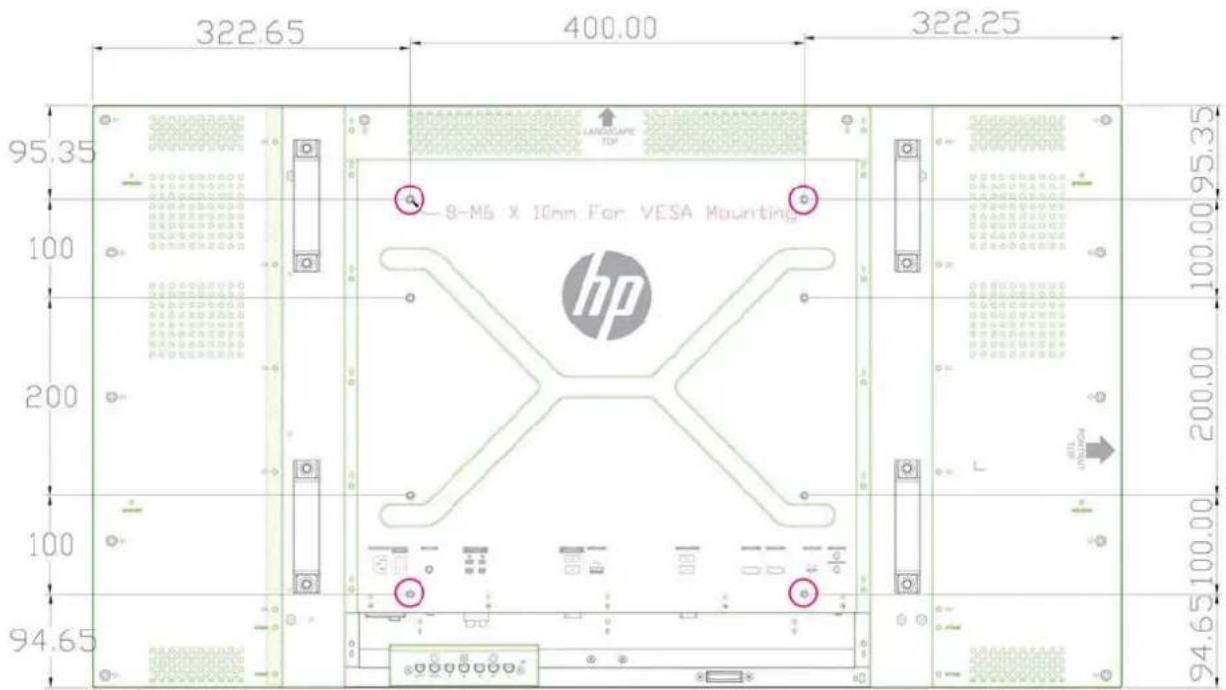
Recognizing preset display resolutions
The display resolutions listed below are the most commonly used modes and are set as factory defaults. This display automatically recognizes these preset modes and they will appear properly sized and centered on the screen.
Preset display modes
Table B-2 Factory preset display modes
| Preset Pixel format Horizontal frequency | (kHz) | Vertical Frequency (Hz) |
| 1 640 x 480 31.469 59.940 | ||
| 2 640 x 480 37.861 72.809 | ||
| 3 640 x 480 37.500 75.000 | ||
| 4 720 x 400 31.469 70.087 | ||
| 5 800 x 600 37.879 60.317 | ||
| 6 800 x 600 48.077 72.188 | ||
| 7 800 x 600 46.875 75.000 | ||
| 8 832 x 624 49.726 74.551 | ||
| 9 720 x 480 31.469 59.940 | ||
| 10 1024 x 768 48 363 60.004 | ||
| 11 1024 x 768 56 476 70.069 | ||
| 12 1024 x 768 60 023 75.029 | ||
| 13 1152 x 720 44 86 60.00 | ||
| 14 1152 x 870 68 68 75.06 | ||
| 15 1152 x 900 71 71 76.05 | ||
| 16 1280 x 720 45 00 59.94 | ||
| 17 1280 x 768 47 396 59.995 | ||
| 18 1280 x 800 49 702 59.810 | ||
| 19 1280 x 960 60 00 60.00 | ||
| 20 1280 x 1024 63.981 60.020 | ||
| 21 1280 x 1024 79.976 75.025 | ||
| 22 1366 x 768 47 712 59.790 | ||
| 23 1440 x 900 55 935 59.887 | ||
| 24 1440 x 900 55 469 59.901 | ||
| 25 1600 x 900 55 935 59.887 | ||
| 26 1600 x 1000 61.648 60.00 | ||
| 27 1600 x 1200 75.000 60.000 | ||
| 28 1680 x 1050 65.290 59.954 | ||
| 29 1920 x 1080 67.5 60.00 | ||
| 30 1920 x 1200 74.038 59.950 |
In addition to these preset modes, the display will store up to 20 user modes. User modes are lost when the OSD Factory Reset option is used. In addition to frequency and resolution, a user mode includes the Horizontal Position, Vertical Position, Clock, Clock Phase, and Auto Adjustment settings.
High definition video formats
| Preset Timing Name | Pixel Format Horz Freq (kHz) | Vert Freq (Hz) | Pixel Rate (MHz) | OSD Display | |
| 1 480i | 720x480 | 15.734 59.940 13.500 480i | |||
| 2 480p | 720x480 | 31.469 59.940 27.000 480p | |||
| 3 720p60 | 1280x720 | 45.000 60.000 74.250 720p-60Hz | |||
| 4 1080i60 | 1920x1080 | 33.750 60.000 74.250 1080i-60Hz | |||
| 5 576i | 720X576 | 15.625 50.000 13.500 576i | |||
| 6 576p | 720X576 | 31.250 50.000 27.000 576p | |||
| 7 720p50 | 1280X720 | 37.500 50.000 74.250 720p-50Hz | |||
| 8 1080i50 | 1920x1080 | 28.125 50.000 74.250 1080i-50Hz | |||
| 9 | 1080p60 | 1920x1080 | 67.500 | 60.000 | 148.500 |
| 10 | 1080p50 | 1920x1080 | 56.250 | 50.000 | 148.500 |
Display quality and pixel policy
| Defect Type Allowable Occurrences |
| Bright dot* None |
| Dark dot** Five maximum |
*A bright dot is a pixel that is always on. If two of its three colors (RGB) are always on, that is also a bright dot.
**A dark dot is a pixel that is always off. If two of its three colors (RGB) are always off, that is also a dark dot.
Power indicator
| Mode LED indicator light |
| Full power Green |
| Low power Red |
| Power off Off |


- ABOUT THIS GUIDE
- TABLE OF CONTENTS
- PRODUCT FEATURES
- SAFETY AND MAINTENANCE GUIDELINES
- SETTING UP THE DISPLAY
- OPERATING THE DISPLAY
- APPENDIX A TROUBLESHOOTING
- APPENDIX B TECHNICAL SPECIFICATIONS
- HP DIGITAL SIGNAGE DISPLAYS
- ACCESSORIES
- OPTIONAL ACCESSORIES
- IMPORTANT SAFETY INFORMATION
- MAINTENANCE GUIDELINES
- CLEANING THE DISPLAY
- CLEANING THE PROTECTIVE GLASS OVERLAY ON SELECT MODELS
- SHIPPING THE DISPLAY
- UNPACKING
- IDENTIFYING DISPLAY COMPONENTS
- CONNECTING THE SPEAKERS (SOLD SEPARATELY)
- DISPLAY CONTROL PANEL
- CONTROL LABEL FUNCTION
- IDENTIFYING REMOTE CONTROL BUTTONS
- SETTING UP THE REMOTE CONTROL
- MOUNTING A SINGLE DISPLAY ON A STAND (SOLD SEPARATELY)
- INSTALLING THE HP FRAME SYSTEM (SOLD SEPARATELY)
- SECURING THE DISPLAY
- CONNECTING CABLES
- CONNECTING MULTIPLE DISPLAYS TO ONE PLAYER
- CONNECTING MULTIPLE DISPLAYS WITH VIDEO OVER ETHERNET (VOE)
- CONNECTING MULTIPLE DISPLAYS WITH TILE MODE
- MOUNTING THE DISPLAY
- MOUNTING IN PORTRAIT POSITION
- CONSIDERATIONS FOR WALL MOUNTING
- SOFTWARE AND UTILITIES
- THE INFORMATION FILE
- THE IMAGE COLOR MATCHING FILE
- INSTALLING THE DRIVER, .INF AND .ICM FILES
- INSTALLING FROM THE DISC
- DOWNLOADING FROM THE WEB
- INSTALLING MANAGEMENT SOFTWARE
- USING THE ON-SCREEN DISPLAY MENU
- CONTROLLING DISPLAYS WITH IR DAISY CHAIN
- SETTING UP IR DAISY CHAIN
- CONTROLLING DISPLAYS WITH THE IR REMOTE CONTROL
- NAVIGATING WITH THE INFRARED REMOTE CONTROL
- NAVIGATING WITH THE CONTROL PANEL
- OSD MENU SELECTIONS
- POWER ON DELAY
- USING KEY LOCK
- SETTING THE BACKLIGHT LEVEL
- PREVENTING AND FIXING GHOST IMAGES
- USING TILE MODE
- OPTIMIZING ANALOG IMAGES
- TUNING COLOR
- A TROUBLESHOOTING
- SOLVING COMMON PROBLEMS
- USING ONLINE TECHNICAL SUPPORT
- PRODUCT SUPPORT
- PREPARING TO CALL TECHNICAL SUPPORT
- B TECHNICAL SPECIFICATIONS
- HP DIGITAL SIGNAGE DISPLAY
- RECOGNIZING PRESET DISPLAY RESOLUTIONS
- PRESET DISPLAY MODES
- DISPLAY QUALITY AND PIXEL POLICY
- POWER INDICATOR
Brand : HP
Model : LD4730G
Category : Monitor