
VL-V591 - Intercom PANASONIC - Free user manual and instructions
Find the device manual for free VL-V591 PANASONIC in PDF.


| Product Type | Video Intercom System |
| Model | Panasonic VL-V591 |
| Display | 7-inch color LCD touchscreen |
| Dimensions (monitor) | 200 × 130 × 30 mm |
| Weight (monitor) | 500 g |
| Power Supply | AC 100-240 V, 50/60 Hz (adapter included) |
| Power Consumption | Standby: 2 W, Active: 8 W |
| Camera | 1/4-inch CMOS sensor, 640×480 resolution |
| Night Vision | Infrared LEDs, range up to 5 m |
| Audio | Two-way hands-free, echo cancellation |
| Door Unlock | Electric strike release (12 V DC) |
| Intercom Features | Call, monitor, talk, unlock, intercom between units |
| Memory | Up to 100 visitor snapshots |
| Wireless | 2.4 GHz digital cordless (optional handsets) |
| Mounting | Wall-mount (bracket included) |
| Operating Temperature | 0 °C to 40 °C |
| Maintenance | Clean with a soft, dry cloth; avoid solvents |
| Safety | Low voltage (SELV), CE marked |
| Spare Parts | Available via Panasonic service centers |
| Warranty | 2 years (depending on region) |
Frequently Asked Questions - VL-V591 PANASONIC
User questions about VL-V591 PANASONIC
0 question about this device. Answer the ones you know or ask your own.
Ask a new question about this device
Download the instructions for your Intercom in PDF format for free! Find your manual VL-V591 - PANASONIC and take your electronic device back in hand. On this page are published all the documents necessary for the use of your device. VL-V591 by PANASONIC.
USER MANUAL VL-V591 PANASONIC
Installation and Operation Guide
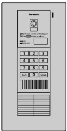
Lobby Station
Model No. VL-V591
Contents
Introduction
System component 2
Included items 2
Important Information
For your safety ....3
Important safety instructions....4
For best performance ....4
Other information....4
Controls
Location of controls....5
Installation
Before installation....6
Installing the lobby station....7
Wiring schematic diagram....10
Programming
How to program the settings....12
Registering room numbers ....13
Setting the PIN (Personal Identification Number) .....14
Setting the time how long the door remains open.....14
Using the Lobby Station
Calling a room from the lobby station....15
Opening the door using the PIN
(Personal Identification Number)....15
General Information
Cleaning 16
Specifications ....16
Other Information....16
Thank you for purchasing a Panasonic product.
Please read this guide before using the unit and save it for future reference.
Panasonic Corporation
1006, Oaza Kadoma, Kadoma-shi, Osaka 571-8501, Japan
http://www.panasonic.com
System component
The lobby station can be connected to up to 20 main monitor stations (in each room).
For details on the main monitor stations that are compatible with the lobby station, see the table below.
In this document, examples are shown with connections made to the VL-MW251 main monitor station. Depending on the main monitor station used, operations may differ from those explained in this document. Please read the documentation of your main monitor station.
![graph TD subgraph "Common entrance" A["Main unit"] --> B["Lobby station"] B --> C["Power supply unit"] C --> D["Power plug (220 V - 240 V AC)"] D --> E["Door opener (Optional)"] end subgraph "Resident" F["Room"] --> G["Main monitor station Example: VL-MW251"] G --> H["Door station Example: VL-V566"]…](/content/2026/06/1378469/images/a3494f8a5e41d322023bd4b6254c9dc43839dc8caf52b80b2838c8771ef06b79.jpg)
■ System component table (as of October, 2017)
| Place | Common entrance | Resident | |
| Unit name | Lobby station | Main monitor station (Main monitor) | Door station |
| Model no. | VL-V591 | VL-MW251, VL-MV30, VL-MV71, VL-MV72, VL-MVN511, VL-MWD272, VL-MWD273, VL-MW274, VL-MWD501 | The types and number of door stations that can be connected differs depending on the main monitor used. Refer to the documentation of your main monitor station. |
| Connectable number | 1 20 (total) | ||
Note:
- For details on optional units that can be connected to the main monitor stations, see the operating instructions of the main monitor stations.
- If units that are not specified in the table above are connected, the lobby station will not work properly. ●The available products differ depending on your region. For more information, please consult your dealer.
Included items
①

②

③

④⑤⑥⑦
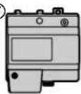


| No. Item Quantity Notes | |||
| 1 | Main unit | 1 | Consists of the upper cabinet and lower cabinet (page 8). |
| 2 | Flush mounted box | 1 | ---- |
| 3 | Screw (4 mm x 25 mm)* 1 | 4 | For the flush mounted box |
| 4 | Power supply unit | 1 | Model No. VL-PS241 |
| 5 | AC cable | 1 | For the power supply unit |
| 6 | Cable binder* 2 | 1 | |
| 7 | Screw (4 mm x 40 mm)* 2 | 2 | |
*1 Attached to the side of the main unit. *2 Attached to the power supply unit.
For your safety
To prevent severe injury and loss of life/property, read this section carefully before using the unit to ensure proper and safe operation of your unit.
WARNING
Power connection
- Use only the power source marked on the unit. If you are not sure of the type of power supplied to the building, consult your dealer or local power company.
- Use only the power source marked on the unit. If you are not sure of the type of power supplied to the building, consult your dealer or local power company.
- Use only the specified power supply unit.
- Do not place objects on the power cable. Install the unit where no one can step or trip on the cable.
- Do not overload power outlets and extension cords. This can result in the risk of fire or electric shock.
- Completely insert the power plug into the power outlet. Failure to do so may cause electric shock and/or excessive heat resulting in a fire.
- Regularly remove any dust, etc. from the power plug by pulling it from the power outlet, then wiping with a dry cloth. Accumulated dust may cause an insulation defect from moisture, etc. resulting in a fire.
- Unplug this unit from power outlets if it emits smoke, an abnormal smell or makes unusual noise. These conditions can cause fire or electric shock. Confirm that smoke has stopped and contact an authorized service center.
- Never touch the plug with wet hands. Danger of electric shock exists.
- Do not connect a power cable to a terminal that is not specified in this guide. Connecting to the wrong terminal may cause electric shock and/or excessive heat resulting in a fire.
Installation
- Leave installation work to the dealer. Installation work requires technique and experiences. Failure to observe this may cause fire, electric shock, injury, or damage to the product. Consult the dealer.
- Electrical connection work should be performed by certified personnel only. Certification is required for performing electrical connection work. Consult your dealer.
- Do not install the product in a place where there is high humidity.
- Do not install the power supply unit in the following places:
- Places where the power supply unit may be splashed with water or chemicals.
- Places where there is a high concentration of dust, or high humidity.
- Do not allow the power cable or power plug to be excessively pulled, bent or placed under heavy objects.
- Do not make any wiring connections when the power supply is turned on.
● Never install wiring during a lightning storm.
- When existing wires are used, it is possible that they contain AC voltage. Electric shock or unit damage could result. Contact an authorized service center.
Operating safeguards
- To reduce the risk of electric shock, do not disassemble this unit. Refer servicing to an authorized service center when service is required. Opening or removing covers may expose you to dangerous voltages or other risks. Incorrect reassembly can cause electric shock when the unit is subsequently used.
- Do not touch the power supply unit/power plug during an electrical storm. There may be a remote risk of electric shock from lightning.
- Never push any objects through slots in the power supply unit. This may result in the risk of fire or electric shock. Never spill any liquid on the power supply unit.
- Unplug this unit from power outlets and refer servicing to an authorized service center when the following conditions occur: A. If the power cable is damaged or frayed. B. If metal objects have been dropped inside the unit. C. If the power supply unit has been exposed to rain or water, or liquid has been spilled into the power supply unit. D. If the unit has been dropped or physically damaged.
CAUTION
Installation and relocation
- The power plug is used as the main disconnect device. Ensure that the power outlet is installed near the product and is easily accessible.
- Install the unit securely adhering to the instructions in this guide to prevent it from falling off the wall. Avoid installing onto low-strength walls, such as gypsum board, ALC (autoclaved lightweight concrete), concrete block, or veneer (less than 18 mm thick) walls. Do not install the unit using a different method from the instructions in this guide.
- If the wiring is outdoors, use a protection tube or a surge protector.
- If the wiring is underground, do not make any connections underground.
- If the wiring is underground, use a protection tube.
Important safety instructions
When using this unit, basic safety precautions should always be followed to reduce the risk of fire, electric shock, or personal injury.
- Use only the power cable indicated in this guide.
SAVE THESE INSTRUCTIONS
For best performance
Before using
- When power fails, this unit cannot be used.
Environment
- When you leave the unit unused for a long period of time, unplug it from the power outlet.
- The power supply unit should be kept away from heat sources such as heaters, etc. It should not be placed in rooms where the temperature is less than 0°C or greater than 40°C. Damp basements should also be avoided.
Other information
- Panasonic assumes no responsibility for injuries or property damage resulting from failures arising out of improper installation or operation inconsistent with this documentation.
- If you stop using the unit, remove the unit from the wall to prevent it from falling off.
- After the installation, explain all precautions and warnings to the customers before use.
- Contact the dealer where you purchased this unit for repair.
Note for product disposal, transfer, or return
- This product can save the PIN required to open the door. To protect your privacy/confidentiality, we recommend that you change the PIN to the default (0000) before you dispose of, transfer or return the product (page 14).
Location of controls Main unit
Upper cabinet front view

Upper cabinet rear view
The figure below shows the appearance when the lower cabinet is removed (page 8).

① Camera ② Lens cover ③ BUSY indicator
Lights when the called main monitor station is in use.
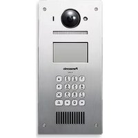
④ DOOR OPEN indicator - Lights when the door of the common entrance is opened. ⑤ Keypad ⑥ [CLR] (CLEAR) button
To stop the operation.
⑦ Speaker ⑧ Microphone ⑨ Room number display ⑩ [CALL] button
When a visitor presses the call button after entering the room number, a ringer tone will ring.
⑪ Room number plate - You can write down room numbers on this plate by removing the rear cover from the upper cabinet. ⑫ Rear cover (for the room number plate) ⑬ Camera angle control lever (page 8)
⑭ PROGRAM switch
To register room numbers and program other settings (page 12-14). Use a pointed object such as a pen to press this switch.
⑮ RESET switch
To reset the unit if it is not working properly. (The program settings are not affected.) Use a pointed object such as a pen to press this switch.
⑯ BACKLIGHT COMPENSATION switch (page 9) ⑰ Speaker volume switch (page 9) ⑱ Water drain holes - These holes allow rain water to drain. Do not cover them.
■ Lobby station image quality
The following phenomena may occur. They are not malfunctions.
When the sun can be seen, its center appears as a black dot. - At night or when there is poor lighting in the doorway, the image colors become unclear. If there is a light in the doorway, the image may appear greenish. - During the daytime or if there is bright light in the doorway, the color of the visitor's clothing may appear differently to the actual color.
Before installation
Important:
● To avoid malfunction or communication disturbances, do not install the lobby station in the following locations:
- Places where vibration or any other kind of impact occurs.
– Places near hydrogen sulfide.
- Do not place other devices or obstacles in the area around the main unit shown in the figure.
- Do not install the power supply unit in the following places:
- Places where the power supply unit may be splashed with water or chemicals.
- Places where there is a high concentration of dust, or high humidity.

Installation position of the main unit and camera range
Installing on a vertical flat wall
Side view when the camera is facing forwards at 0° (default).
Example: Installation height is 1330 mm (standard position).

Installing on a tilted pedestal
Side view when the camera is installed lower than the standard position, and facing upwards at 15° .
Example: Installation height is 980 mm.

Top view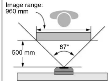
- Do not install on a pedestal tilted at less than 45°.
Side view when the camera is installed on a pedestal tilted at 60° , and facing forwards at 0° (default).
Example: Installation height is 1100 mm.
Side view when the camera is installed on a pedestal tilted at 45° , and facing downwards at 5° .
Example: Installation height is 1120 mm.

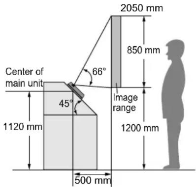
The camera angle can be adjusted using the camera angle control lever on the rear of the upper cabinet (page 8), so that the image range can be changed.
Note:
● The measurements and angles are for reference purposes and may vary depending on the environment.
- If a strong light is shining on the main unit, the visitor's face may not be distinguishable.
Do not place the main unit in the following locations.
- Where most of the background is the sky.
- Where the background is a white wall, and direct sunlight will reflect off it.
- Where direct sunlight will shine on the main unit.
- Do not place the main unit in locations where echoing occurs, causing the unit to beep frequently. ● Make sure the rear of the main unit is not subject to water.
Installing the lobby station
Installing the power supply unit on the wall
A DC cable is not included. You need to prepare one. Refer to "Wire type and distance" (page 11).
About the installation location
- The AC cable plug is used as the main disconnect device. Ensure that the power outlet is installed near the product and is easily accessible.
- A readily accessible disconnect device shall be incorporated external to the equipment.
- External disconnect device must be certified and have a creepage and clearance distance of 3 mm or more.
Precautions for wiring
- Make sure that the power supply unit is unplugged before performing any wiring work. ● Always connect AC or DC cables to the appropriate connector or connection terminal.
- To prevent the DC cable from disconnecting and to prevent electric shock, secure the DC cable using the cable binder (accessory) and attach the cable cover.
How to connect the AC cable and DC cable:
Connect the power supply unit (accessory), the AC cable (accessory), and a DC cable (locally procured).

Power Supply Unit (VL-PS241) side: ① 25 mm ② 7 mm Lobby Station (VL-V591) side: ① 52 mm or more ② 12 mm
Front view


*1 Make sure that there are no bare wires exposed outside the product.
Power supply unit (with cable cover removed)

⑪ DC cable binder hole
1 Strip the DC cables as follows: DC cable (①, ②) 2 Remove the screws (③) and then remove the cable cover (④). 3 Connect the AC cable (⑤) (accessory) to the AC IN connector (⑨) on the top of the power supply unit. Next, connect the DC cable (⑦) (locally procured) to the DC OUT terminal (⑩) on the bottom of the power supply unit, and then secure the wires by tightening the screws (⑥).
- Recommended torque: 0.45 N·m {4.6 kgf·cm}

CAUTION
Insert the cables firmly all the way into the connector and terminals. If the cables are not inserted all the way, heat may be generated.
4 Use the cable binder (⑧) (accessory) to secure the DC cable (⑦) (double-coated area) to the power supply unit. 5 Make sure to replace the cable cover (④).
Wall mounting
Attach the power supply unit to the wall securely. ① Screws (accessory) x 2

Installing the flush mounted box in the wall
Drilling dimension of wall surface for the flush mounted box
(Pitch of fixing screw)


Open the knockout holes of the flush mounted box, and put the wires from each room and the door opener, and the DC cable from the power supply unit through the holes. Mount the box in the wall.
Knockout holes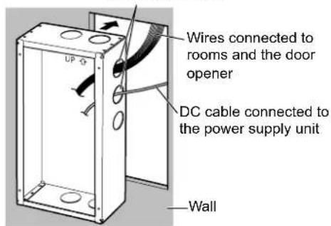
Installing the main unit
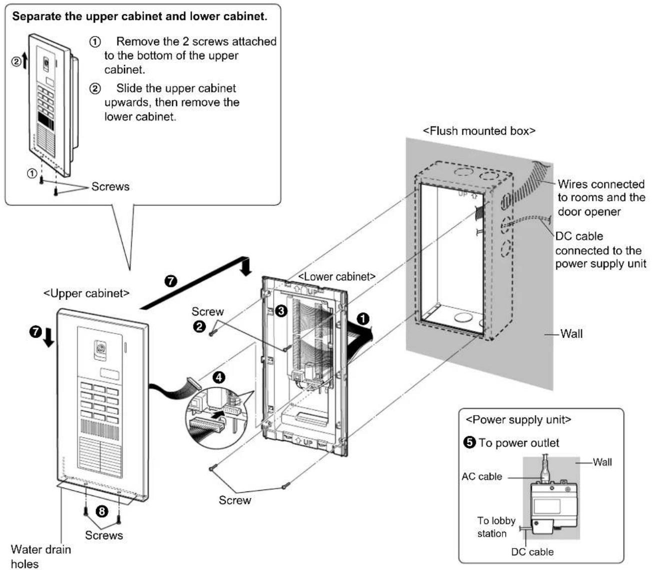
After installing the power supply unit and the flush mounted box (page 7), install the main unit.
Important:
- On the bottom surface of the upper cabinet, there are holes to allow water to drain. Do not cover them up when installing.
■ Adjusting the camera angle

Downwards (maximum 5°)

Upwards (maximum 15°)
Facing forwards Facing upwards Facing downwards


① Put the wires and the DC cable from the flush mounted box through the rear gaps of the lower cabinet.
② Install the lower cabinet on the flush mounted box using a screw (4 mm x 25 mm).
- Be sure to align the lower cabinet parallel to the flush mounted box when screwing.
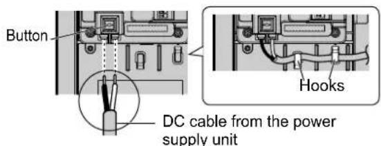
③ Connect the wires and the DC cable to the terminals on the lower cabinet. (Refer to "Wiring schematic diagram" on page 10.)
- Connect the wires as follows.
While pressing on the button with a pointed object such as a screwdriver, insert the wire into the terminal connector. (To disconnect a wire, press on the button while pulling out.)

- Connect the DC cable as follows.
Insert the wire inward securely while pressing the button. (Refer to "How to connect the AC cable and DC cable" of "Installing the power supply unit on the wall" on page 7.)
④ Connect the upper cabinet cable connector firmly with the connector on the lower cabinet.
⑤ Connect the AC cable of the power supply unit to a power outlet (220 V – 240 V AC).
If necessary, adjust the camera angle (page 8). If necessary, set the speaker volume and backlight compensation feature (see below).
6 Press and hold the PROGRAM switch on the rear of the upper cabinet for about 2 seconds using a pointed object such as a pen.
- Hold the upper cabinet tight so as not to drop it.

⑦ Slide the upper cabinet downwards and fix it to the lower cabinet.
- Tape the cables connected to the upper cabinet to an appropriate position on the upper cabinet to prevent them from becoming pinched between the upper cabinet and lower cabinet.
Register room numbers and program other settings (page 12-14).
Set each main monitor station (page 11).
Check the connections to the rooms by calling them from the lobby station and opening the door of the common entrance from the main monitor stations (page 15).
Screw on the bottom of the upper cabinet to install it to the lower cabinet.
Setting the speaker volume/backlight compensation
Speaker volume switch
2 levels are available (High/Low).

Note:
- When a main monitor station connected to the lobby station is connected to a PBX (page 10), set the speaker volume to the low level.

Backlight compensation switch
To compensate for backlight dimming, set to "ON".

BACKLIGHT COMPENSATION
Wiring schematic diagram
Set up correctly according to the following wiring schematic diagrams and "Wire type and distance" (page 11). 20 main monitor stations can be connected to terminals 1 to 20 on the lobby station.
- For main monitor station system, refer to the operating instructions of the main monitor stations. An example is shown below.
![graph TD A["Main monitor station system"] --> B["Terminal number"] B --> C["Lobby station (lower cabinet)"] B --> D["Door station"] D --> E["Main monitor station *1"] E --> F["Main monitor station system"] E --> G["Terminal box (4-conductor wiring)"] G --> H["Door (Door Opener)"] H --> I["Door (Door…](/content/2026/06/1378469/images/605d1bac17a613ea76030fdecf91775dae23dfbce0b1547999ebb47d1db7e633.jpg)
*1 Connecting the lobby station to the main monitor stations
- Be sure to perform the following to ensure proper operation:
- Connect terminal D1/D2 of each numbered terminal (1 - 20) on the lobby station to the wire from D1/D2 on the main monitor station.
- Connect terminal S1/S2 of each numbered terminal (1 - 20) on the lobby station to the wire from S1/S2 on the main monitor station.
*2 Connecting the lobby station to a door opener (for common entrance)
- Before connecting to a door opener, make sure that:
- K1/K2 terminal: Normally open/Actively short
- The door opener is less than 30 V AC (1 A), 24 V DC (1 A). Do not connect to a door opener that is more than 30 V AC (1 A), 24 V DC (1 A), otherwise the unit may be damaged.
- K1/K2 terminal on the lobby station is not the power supply to the door opener. If the door opener needs a power supply device to connect to the lobby station, contact the dealer where you purchased the door opener.
- After connecting the door opener to the lobby station, confirm that the door can be properly locked/unlocked using the main monitor station depending on the status of the door opener (page 11). If you have set a PIN (page 14), confirm that the door can be properly locked/unlocked using the PIN depending on the status of the door opener (page 15).
■ Setting the main monitor stations
"LOBBY CONNECTION" setting:
- After connecting to the main monitor stations to the lobby station, change the setting of "LOBBY CONNECTION" to "YES" using the main monitor stations. (Refer to the Operating Instructions of the main monitor stations.)
"DOOR KEY" setting:
- Confirm that the door can be properly locked/unlocked depending on the status of the door opener. The door of the common entrance can be opened by each main monitor station. The time how long the door remains open by the door opener can be set using the main monitor station. (The default setting is "5 SEC OPEN".) If your door opener automatically locks the door when it is closed, we recommend setting the [DOOR KEY] button on the main monitor station to "2 SEC OPEN". (Refer to the operating instructions of the main monitor stations.)
Wire type and distance
- Wire (between the lobby station and the main monitor station):
| Type Distance Loop resistance | ||
| General cable CAT-3 Maximum 50 m | 10 Ω or lower | |
| General cable 22 AWG (ø 0.65~0.8) Maximum 100 m |
- DC cable (between the lobby station and the power supply unit):
| Type Distance Loop resistance | ||
| Single-wired cable ø 1.2~2.0 | Maximum 50 m 10 Ω | or lower |
| Twisted-wired cable 16~14 AWG |
How to program the settings
To register room numbers or program other settings, you need to enter programming mode using the PROGRAM switch on the rear of the upper cabinet (page 5). To press the PROGRAM switch, use a pointed object such as a pen.
![BUSY indicator, DOOR OPEN indicator, 1 2 3, 4 5 6, 7 8 9, CLR 0 CALL, [CALL].](/content/2026/06/1378469/images/553906a452738b663794fab4e82e1cbe21ab041244cf004ae6cfa36032001043.jpg)
1 To enter programming mode, press and hold the PROGRAM switch for about 2 seconds during standby. 2 Enter the desired function code, then press [CALL].
| Function Code | |
| Registering room numbers | 001 |
| Confirming a room number | 002 |
| Confirming all room numbers | 003 |
| Canceling the registration of a room number | 004 |
| Canceling the registration of all room numbers | 044 |
| Setting the PIN | 005 |
| Setting the time for how long the door remains open using the PIN | 006 |

3 Perform the operation according to the function. To save the setting, press [CALL].
• To end the setting, press [CLR]. 4 To end programming mode, enter [9][9][9], then press [CALL]. • The unit returns to standby.
Note:
- The DOOR OPEN indicator/BUSY indicator function as follows while programming.
| Setting status DOOR OPEN indicator BUSY indicator | ||
| The unit is in programming mode. OFF Flashes rapidly | ||
| The function code is entered. You can set the function. OFF Flashes slowly | ||
| The unit is waiting to save the setting. Flashes slowly Flashes slowly | ||
| The setting is being saved. Lights (for 1 second) Flashes slowly | ||
| Error (such as when an invalid number is entered.) | ---- Lights |
- While programming the function in steps 2 to 3, you can stop programming by pressing [CLR].
Registering room numbers
Register each room number to each terminal number (01-20) (page 10).
1 Press and hold the PROGRAM switch for about 2 seconds during standby. 2 Enter [0][0][1], then press [CALL]. 3 Enter the desired terminal number (001-020) (in 3 digits), then press [CALL].
- To correct the number, press [CLR], then repeat this step.
4 Enter the desired room number (within 3 digits), then press [CALL].
- The terminal number and room number are displayed alternately.
- To correct the number, press [CLR], then repeat from step 3.
- “Err” (Error) is displayed when a registered room number is entered. Press [CLR], then repeat from step 3.
5 Press [CALL] again to save the setting.
- After the room number is registered, the display on the right is shown.
- To register other room numbers, repeat steps 3 to 5.
- To confirm the room numbers, press [CLR], then continue from step 2 of "Confirming all room numbers" below.
6 To end the registration, press [CLR]. 7 To end programming mode, enter [9][9][9], then press [CALL].
■ To change a room number
Enter the new room number in step 4. The previous room number is replaced with the new one.

Confirming a room number
1 Press and hold the PROGRAM switch for about 2 seconds during standby. 2 Enter [0][0][2], then press [CALL]. 3 Enter the desired terminal number (001-020) (in 3 digits), then press [CALL].
- The terminal number and the room number are displayed alternately.
- To confirm another room number, press [CALL], then repeat this step.
4 When finished, press [CLR]. 5 To end programming mode, enter [9][9][9], then press [CALL].
Confirming all room numbers
1 Press and hold the PROGRAM switch for about 2 seconds during standby. 2 Enter [0][0][3], then press [CALL].
- The terminal number 01 and the room number are displayed alternately.
3 To confirm the next room number, press [CALL]. - The next terminal number and the room number are displayed. 4 When finished, press [CLR]. 5 To end programming mode, enter [9][9][9], then press [CALL].
Canceling the registration of a room number
1 Press and hold the PROGRAM switch for about 2 seconds during standby. 2 Enter [0][0][4], then press [CALL]. 3 Enter the desired terminal number (001-020) (in 3 digits) for the room number to be erased, then press [CALL].
- “dEL” and the terminal number are displayed alternately.
4 Press [CALL] to cancel the registration. - To delete another room number, repeat from step 3. 5 To end canceling the registration, press [CLR]. 6 To end programming mode, enter [9][9][9], then press [CALL].
Canceling the registration of all room numbers
1 Press and hold the PROGRAM switch for about 2 seconds during standby. 2 Enter [0][4][4], then press [CALL].
- "ALL" and "dEL" are displayed alternately.

- To stop deleting numbers, press [CLR].
3 Press [CALL] to cancel the registration.
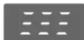
4 To end programming mode, enter [9][9][9], then press [CALL].
Setting the PIN (Personal Identification Number)
When a separate door opener is connected to the lobby station, the PIN is used to open the door of the common entrance. The default PIN is "0000" (the feature is deactivated). Once you change the PIN, the door can be opened using the PIN.
1 Press and hold the PROGRAM switch for about 2 seconds during standby. 2 Enter [0][0][5], then press [CALL]. 3 Enter the 4-digit PIN (0001-9999).
- To correct the number, press [CLR], then start from step 2.
4 Press [CALL].
- When "Err" (Error) is displayed, press [CLR], then start from step 2.
5 To end programming mode, enter [9][9][9], then press [CALL].
■ To change the PIN again
Enter the new PIN in step 3. The old PIN is replaced with the new one.
■ To return to the default setting
Enter "0000" in step 3. (The feature is deactivated.)
Note:
● Take the following measures to avoid security breaches.
- To prevent unauthorized access to this unit, change the PIN regularly.
- Keep the PIN confidential.
- Select a complex, random PIN that cannot be easily guessed.
Setting the time how long the door remains open
You can select how long the door of the common entrance remains open when the PIN is entered on the lobby station. The default setting is "5" (5 seconds).
- After connecting the door opener to the lobby station (page 9), confirm that the door can be properly locked/unlocked using the PIN depending on the status of the door opener (page 15). If your door opener automatically locks the door when it is closed, we recommend selecting "2" (2 seconds).
1 Press and hold the PROGRAM switch for about 2 seconds during standby. 2 Enter [0][0][6], then press [CALL]. 3 Select the time (2 seconds to 7 seconds) by entering 2 to 7. 4 Press [CALL].
- When "Err" (Error) is displayed, press [CLR], then start from step 2.
5 To end programming mode, enter [9][9][9], then press [CALL].
Calling a room from the lobby station
1 Enter the room number (set in "Registering room numbers" on page 13) using the keypad.
- To correct the number, press [CLR], then enter the room number again.
2 Press [CALL] to call the room.
- You will hear a ring tone. To stop calling, press [CLR].
3 Wait for a reply.
Note:
• The BUSY indicator lights when:
- an invalid room number is entered.
– the main monitor station is in use.
– the main monitor station power is off.
Opening the door using a main monitor station
When a separate door opener is connected to the lobby station, you can open the door using a main monitor station.
1 To open the door, press [DOOR KEY] on the main monitor station after answering a call from the lobby station.
- When the door is opened the DOOR OPEN indicator lights on the lobby station.
- Door opener allows each main monitor station to open the door for the time specified in "Setting [DOOR KEY] button". Refer to the operating instructions of the main monitor stations.
Opening the door using the PIN (Personal Identification Number)
The door of the common entrance can be opened by entering the PIN on the keypad.
To use this feature, you need to change the PIN from the default (0000) (page 14).
1 While keeping pressing [CLR], press and hold [CALL] for about 2 seconds, then release both [CLR] and [CALL].
2 Enter the 4-digit PIN, then press [CALL].
- When the door is opened, the DOOR OPEN indicator lights.
- The door opener allows you to open the door for the time specified in "Setting the time how long the door remains open" (page 14).

Note:
- "Err" (Error) is displayed when the following occurs:
- The wrong PIN is entered in step 2. Press [CLR], then start from step 1 again.
- A 5-digit PIN is entered in step 2. Press [CLR], then start from step 1 again.
- The PIN has not been set (page 14). The PIN feature is deactivated.
- If you do not press a key within 10 seconds, the display returns to standby. Start again from step 1.
- If you forget the PIN, contact your building manager.
Cleaning
Clean the unit with a soft, dry cloth when cleaning. For excessive dirt, wipe the unit with a slightly damp cloth.
Important:
- Do not use anything containing alcohol, polish powder, powder soap, benzine, thinner, wax, petroleum, or boiling water. Also do not spray with insecticide, glass cleaner, or hair spray. This could cause a change in color or quality.
Specifications
Power supply:
Input: 220-240 V AC, 0.2 A, 50/60 Hz
Output: 24 V DC, 0.6 A
Current consumption:
Standby: 0.02 A
During operation: 0.03 A
Dimensions: Main unit:
Approx. height 358 mm x width 180 mm x depth 17.3 mm (Excluding sections embedded into the wall)
Power supply unit:
Approx. height 104 mm x width 100 mm x depth 54 mm (Excluding protruding sections)
Mass (Weight): Main unit: Approx. 2.0 kg
Power supply unit: Approx. 215 g
Operating environment:
Main unit: -10 °C to 50 °C, Up to 90 % RH (Relative Humidity) non condensing
Power supply unit: 0 °C to 40 °C, Up to 90 % RH (Relative Humidity) non condensing
Installation method: Wall mount (Flush mounted box included)
External material: Stainless steel and flame retardant ABS resin
Note:
- Design and specifications are subject to change without notice.
- The pictures and illustrations in this guide may vary slightly from the actual product.
Other Information
Graphical symbols for use on equipment and their descriptions
| 1 | 2 | 3 | 4 | 5 | 6 | --- | ⊥ | ⊥ | ⊥ | ||||||||
| 7 | 8 | 9 | 10 | 11 | 12 | | | ○ | ↓ | ↑ |
- 1. Alternating current (A.C.) 2. Direct current (D.C.) 3. Protective earth 4. Protective bonding earth 5. Functional earth 6. For indoor use only 7. Class II equipment (equipment in which protection against electric shock relies on Double Insulation or Reinforced Insulation) 8. "ON" (power) 9. "OFF" (power) 10. Stand-by (power) 11. "ON"/"OFF" (power; push-push) 12. Caution, risk of electric shock
Information on Disposal in other Countries outside the European Union
The symbol (①) is only valid in the European Union.
If you wish to discard this product, please contact your local authorities or dealer and ask for the correct method of disposal.

For India only
Declaration of Conformity with the requirements of the E-Waste (Management) Rules
The Product is in conformity with the requirements of the reduction of hazardous substances of the E-Waste Rules.
The content of hazardous substance with the exemption of the applications listed in SCHEDULE II of the E-Waste Rules:
- 1. Lead (Pb) – not over 0.1% by weight; 2. Cadmium (Cd) – not over 0.01% by weight;
- 3. Mercury (Hg) – not over 0.1% by weight; 4. Hexavalent chromium (Cr6+) – not over 0.1% by weight;
- 5. Polybrominated biphenyls (PBBs) – not over 0.1% by weight;
- 6. Polybrominated diphenyl ethers (PBDEs) – not over 0.1% by weight.
Disposal information
For the purpose of recycling to facilitate effective utilization of resources, please return this product to a nearby authorized collection centre, registered dismantler or recycler, or Panasonic service centre when disposing of this product.
Please see the Panasonic website for further information on collection centres, etc., or call the toll-free number below.
Website:
http://www.panasonic.com/in/corporate/sustainability/
panasonic-india-i-recycle-program.html
Service helpline: 1800 103 1333 or 1800 108 1333

- INSTALLATION AND OPERATION GUIDE
- LOBBY STATION
- CONTENTS
- INTRODUCTION
- IMPORTANT INFORMATION
- CONTROLS
- INSTALLATION
- PROGRAMMING
- USING THE LOBBY STATION
- GENERAL INFORMATION
- SYSTEM COMPONENT
- NOTE
- INCLUDED ITEMS
- FOR YOUR SAFETY
- WARNING
- POWER CONNECTION
- OPERATING SAFEGUARDS
- CAUTION
- INSTALLATION AND RELOCATION
- IMPORTANT SAFETY INSTRUCTIONS
- SAVE THESE INSTRUCTIONS
- FOR BEST PERFORMANCE
- BEFORE USING
- ENVIRONMENT
- OTHER INFORMATION
- NOTE FOR PRODUCT DISPOSAL, TRANSFER, OR RETURN
- LOCATION OF CONTROLS MAIN UNIT
- UPPER CABINET FRONT VIEW
- UPPER CABINET REAR VIEW
- LOBBY STATION IMAGE QUALITY
- BEFORE INSTALLATION
- IMPORTANT
- INSTALLATION POSITION OF THE MAIN UNIT AND CAMERA RANGE
- INSTALLING ON A VERTICAL FLAT WALL
- SIDE VIEW WHEN THE CAMERA IS FACING FORWARDS AT 0° (DEFAULT)
- SIDE VIEW WHEN THE CAMERA IS INSTALLED LOWER THAN THE STANDARD POSITION, AND FACING UPWARDS AT 15°
- SIDE VIEW WHEN THE CAMERA IS INSTALLED ON A PEDESTAL TILTED AT 60° , AND FACING FORWARDS AT 0° (DEFAULT)
- SIDE VIEW WHEN THE CAMERA IS INSTALLED ON A PEDESTAL TILTED AT 45° , AND FACING DOWNWARDS AT 5°
- INSTALLING THE LOBBY STATION
- INSTALLING THE POWER SUPPLY UNIT ON THE WALL
- ABOUT THE INSTALLATION LOCATION
- PRECAUTIONS FOR WIRING
- HOW TO CONNECT THE AC CABLE AND DC CABLE
- POWER SUPPLY UNIT (WITH CABLE COVER REMOVED)
- WALL MOUNTING
- INSTALLING THE FLUSH MOUNTED BOX IN THE WALL
- INSTALLING THE MAIN UNIT
- ADJUSTING THE CAMERA ANGLE
- SETTING THE SPEAKER VOLUME/BACKLIGHT COMPENSATION
- SPEAKER VOLUME SWITCH
- BACKLIGHT COMPENSATION SWITCH
- WIRING SCHEMATIC DIAGRAM
- SETTING THE MAIN MONITOR STATIONS
- LOBBY CONNECTION" SETTING
- DOOR KEY" SETTING
- WIRE TYPE AND DISTANCE
- HOW TO PROGRAM THE SETTINGS
- REGISTERING ROOM NUMBERS
- CONFIRMING A ROOM NUMBER
- CONFIRMING ALL ROOM NUMBERS
- CANCELING THE REGISTRATION OF A ROOM NUMBER
- CANCELING THE REGISTRATION OF ALL ROOM NUMBERS
- SETTING THE PIN (PERSONAL IDENTIFICATION NUMBER)
- SETTING THE TIME HOW LONG THE DOOR REMAINS OPEN
- CALLING A ROOM FROM THE LOBBY STATION
- OPENING THE DOOR USING A MAIN MONITOR STATION
- OPENING THE DOOR USING THE PIN (PERSONAL IDENTIFICATION NUMBER)
- CLEANING
- SPECIFICATIONS
- INFORMATION ON DISPOSAL IN OTHER COUNTRIES OUTSIDE THE EUROPEAN UNION
- FOR INDIA ONLY
- DECLARATION OF CONFORMITY WITH THE REQUIREMENTS OF THE E-WASTE (MANAGEMENT) RULES
- DISPOSAL INFORMATION
Brand : PANASONIC
Model : VL-V591
Category : Intercom