
Outdoor Siren - Alarm system BOSCH - Free user manual and instructions
Find the device manual for free Outdoor Siren BOSCH in PDF.


| Product Type | Outdoor Siren |
| Brand | Bosch |
| Model | Outdoor Siren |
| Category | Alarm System |
| Dimensions (H x W x D) | 200 mm x 200 mm x 100 mm |
| Weight | 1.2 kg |
| Power Supply | DC 12V, 300 mA |
| Sound Output | 105 dB at 1 m |
| Operating Temperature | -25°C to 60°C |
| Protection Rating | IP55 |
| LED Indicators | Red/Green status LEDs |
| Tamper Protection | Anti-tamper switch |
| Compatibility | Bosch alarm control panels |
| Installation | Wall-mount with included bracket |
| Maintenance | Periodic cleaning with damp cloth |
| Safety | Low voltage operation, weatherproof |
| Spare Parts | Available via Bosch service centers |
| Repairability | Serviceable by qualified technicians |
| Warranty | 2 years limited |
| Manual Languages | Multiple, including English |
Frequently Asked Questions - Outdoor Siren BOSCH
User questions about Outdoor Siren BOSCH
0 question about this device. Answer the ones you know or ask your own.
Ask a new question about this device
Download the instructions for your Alarm system in PDF format for free! Find your manual Outdoor Siren - BOSCH and take your electronic device back in hand. On this page are published all the documents necessary for the use of your device. Outdoor Siren by BOSCH.
USER MANUAL Outdoor Siren BOSCH
The outdoor siren is an add-on for the Bosch Smart Home alarm system. If it detects a break-in, then both the sirens and the integrated flashing lights are activated and signal the break-in both visually and audibly. The outdoor siren is powered by a long-life battery which is charged by the integrated glass solar panel. Alternatively, it can also be powered by a 230 V alternating current or with a direct current of between 5 and 28 V. If this fails, the integrated battery serves as an emergency power supply. The outdoor siren also has an alarm input, a sabotage output and an alarm output, and is therefore also suitable for use in wired burglar alarm systems.
Description of the symbols

Warning!
Note about hazards

Note:
Additional important information

Note about the installation video
Electrical voltage.

Warning: danger of death
⚠ Safety instructions
▶ Do not continue using used batteries, and do not attempt to reactivate them using heat or other means. Do not short circuit batteries. Do not throw batteries into fire!
▶ Do not continue using used batteries, and do not attempt to reactivate them using heat or other means. Do not short circuit batteries. Do not throw batteries into fire!
The device is not a toy! Do not allow children to play with it. Never leave the packaging material lying around unattended. Plastic film and small parts may pose a danger to children.
When remotely or automatically controlling a device, it is not always possible to guarantee that commands are actually executed or that the correct device status is displayed in the app and on other Smart Home display devices because of external circumstances. This may lead to material damage and/or personal injury. Therefore, you must ensure to the greatest extent possible that no person is endangered at the time of remote operation or automated control. Please take special care when setting up or adjusting the remote control or when using the automated control and check the desired functionality at regular intervals.
▶ Do not open up the device. It does not contain any parts to be maintained by the user. If a fault occurs, have the device checked by a specialist.
We accept no liability for material damage or personal injury caused by improper use or failure to observe the safety instructions. In such cases, any guarantee claim becomes void! We accept no liability for consequential damage.
This device may be used by children aged 8 years and above, and by persons with reduced physical, sensory, or mental capabilities, or lack of experience and knowledge, provided they are supervised or have been instructed in the safe use of the device and understand the associated risks.
For safety and approval reasons (CE), the device must not be modified or altered without authorization.
▶ Any use other than that described in the user manual is considered improper and leads to the exclusion of guarantee and liability.
▶ Do not use the device if it has visible external damage, for example to the housing, control elements, or connection sockets, or if it malfunctions. If in doubt, please contact our
There is a risk of explosion! There is a risk of explosive steam.
▶ Only use the device with original components and recommended products from Bosch partners. ▶ Do not paint or cover the device! The alarm is very loud and may cause hearing damage. Maintain a sufficient distance from sirens during audible alarms and protect your hearing. The contents of the integrated spirit level are based on solvent naphtha for frost protection reasons. In the event of a defect and subsequent leaking fluid: Avoid skin contact. There is a risk of skin irritation. In case of skin contact: Wash the affected area with plenty of water.
Warning! Warning! Danger of death if swallowed. In particular, keep the spirit level out of the reach of children.
Notes
The range within buildings can differ significantly from the range in open spaces. In addition to the transmitting power and the receiving properties of the receiver, environmental factors such as humidity, as well as the local structural situation, play an important role. ▶ Do not expose the device to vibrations and mechanical stress. The device is only suitable for use in residential, commercial, and light industrial environments. ▶ Please note that, in accordance with local standards, alerting with audible signal generators outside the monitored property is not permitted.
Product overview
| Item Name | |
| Alarm front/bottom | |
| 1 Solar panel | |
| 2 LED flashing and signal light | |
| 3 Status LED | |
| 4 Locking screw | |
| Wall bracket | |
| 5 Tamper-proof seal adjusting screw | |
| 6 230 V terminal | |
| 7 Spirit level | |
| 8 230 V AC cable bushing | |
| ed. | Cable bushingsafety extra-low voltage 5–28 VDCand connection cable to a burglaralarm system |
| 9 | |
| Siren back | |
| 10 Reset button | |
| 11 Tamper-proof seal | |
| 12 | Cable bushings for safety extra-lowvoltage and cable for burglar alarmsystem |
| 13 Connector compartment cover | |
| 14 Battery compartment cover | |
| Connection compartment with | |
| 15 DIP switches | |
| 16 | Safety extra-low voltage and wiredburglar alarm system connection |
| Battery compartment with | |
| 17 On/off switch | |
| 18 USB charging connector | |
| 19 Battery connector plug | |
| 20 NiMH battery | |

Alarm front/bottom

Connection compartment

Wall bracket

Battery compartment
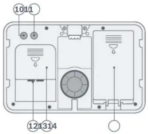
Siren back
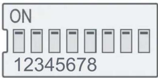
DIP switches factory settings
DIP switch overview (15)
| DIP switches Meaning12345678 | |||||||
| OFF | OFF | Volume off | |||||
| ON | OFF | Volume quiet | |||||
| OFF | ON | Volume medium | |||||
| ON | ON | Volume loud (factory setting) | |||||
| OFF | OFF | OFF | 0 minute alarm duration | ||||
| ON | OFF | OFF | 1 minute alarm duration | ||||
| ON | ON | ON | 3 minutes alarm duration (factory setting) | ||||
| ON | ON | OFF | 5 minutes alarm duration | ||||
| OFF | OFF | ON | 10 minutes alarm duration | ||||
| OFF | ON | OFF | 15 minutes alarm duration | ||||
| ON | OFF | 230 VAC primary power supply | |||||
| OFF | ON | 5-28 VDC primary power supply | |||||
| ON | ON | Solar primary power supply (factory setting) | |||||
| “Legacy” (operation without Bosch Smart Home controller) | |||||||
| “Smart” (factory setting) | |||||||
When operating the siren on the Bosch Smart Home controller and using the solar panel as the primary power supply, no settings need to be changed from the factory settings. You can simply make the settings in your app.
Before making settings, check the legal and technical regulations in your country.
Terminal overview (16)
| Trigger_INDCTrigger_OUT Tamper 5-28V GND TRI+ TRI- NO EOL COM NO EOL COM | |||||||||
| DC_IN Trigger_IN Trigger_OUT Tamper | |||||||||
| +5-28 V | GND TR+ TR- | TriggerNO | TriggerEOL | TriggerCOM | TamperNO | TamperEOL | TamperCOM | ||
| Power supply | Alarm input | Alarm output | Sabotage contact | ||||||
Connection to a wired burglar alarm system
Outdoor siren Wired burglar alarm![graph TD A["DC_IN"] --> B["5..28VDC"] A --> C["GND"] D["TRIGGER_IN"] --> E["TR+"] D --> F["TR-"] G["TRIGGER_OUT"] --> H["NO"] G --> I["EOL"] G --> J["COM"] G --> K["EOL resistor"] L["TAMPER"] --> M["NO"] L --> N["EOL"] L --> O["COM"] L --> P["EOL resistor"] Q["system"] --> R["End"] style A fill:#f9f…](/content/2026/06/1373298/images/f06d70027c486e7f7c21ff3c4c3d238ccf8ee026d58b889b0fc1d30b3f3d5335.jpg)
Power supply: 5–28 V DC, power consumption: 1.5 A–300 mA
Alarm input: Trigger voltage 5–28 V DC (15 mA)
Alarm output: Capacity 30 V DC/1 A max.
Sabotage contact: Capacity 30 V DC/1 A max.

You can also use the explanatory video on our website as an additional aid for mounting, installing and starting up your Bosch Smart Home outdoor siren: www.bosch-smarthome.com/rom/outdoor-siren
The status LED (3) shows the status of the siren using flashing codes.
| Status LED Device status Description | ||
| Battery test/battery status (the LED remains lit as long as the button is pressed) | ||
| Lights green The battery is fully charged. | ||
| Lights yellow The battery is sufficiently charged. | The battery should be charged before installation. | |
| Lights red (or is off) | The battery is not sufficiently charged. | The battery must be charged before installation. |
| Sabotage detected | ||
| Flashes red 3x (every 15 seconds) | The tamper-proof seal has triggered, e.g. during manipulation or incorrect adjustment of the contact. | Check the siren/situation and correctly adjust the tamper-proof seal if needed. |
| Primary power supply failed | ||
| Flashes red (every 4 seconds) | The primary power supply has failed. | Check the power supply you have selected. |
| Status indicator during USB charging | ||
| Flashes yellow The battery is charging | ||
| Lights yellow The battery is fully charged | ||
Mounting
The standards and directives applicable in your country must be observed during planning, set-up, operation and maintenance. Use suitable ladders or steps with appropriate safety approval for mounting. When selecting the mounting location and when drilling, pay attention to the areas where electrical wires run, or to any supply cables. Use the mounting plate for the siren to mark the drill holes. To do this, unscrew the locking screw on the bottom and remove the siren from the mounting plate as shown.
Removing the siren
Removing the siren
- Unscrew the screw (4)
- Push the siren upwards – Pull the siren forwards
i Choose a place of installation with sufficient daylight if you want to operate the siren with the solar panel. Mounting the siren facing south, west or east is particularly suitable for this. Make sure that the solar panel is not permanently shaded, e.g. by trees, houses or canopies. The siren should be at a sufficient height to protect it against manipulation.
In northern Europe ( > 55° latitude), it may be necessary to operate the siren with a permanent power supply because the daylight hours during the winter may not be sufficient to adequately charge the battery with the solar panel.
i Ensure that the signal strength is sufficient in the place of installation chosen. To do this, follow the instructions in the app during start-up.
Hold the mounting plate in the desired position on the wall. Make sure it is correctly oriented. Align the mounting plate with the help of the integrated spirit level or an additional spirit level. Mark the drill holes and drill them. Attach the mounting plate to the wall. If cabling is planned, e.g. external power supply and/or connection to a wired burglar alarm system, route the cable through the openings in the mounting plate intended for this purpose (8/9) before screwing it on. All four screws are required for a firm hold.
Setting the tamper-proof seal on the mounting plate
The siren is protected by a tamper-proof seal. This will trigger an alarm if the siren is removed from the wall of the house without authorisation. After attaching the mounting plate to the wall of the house, the tamper-proof seal must be set correctly. To do this, turn the adjusting screw on the contact clockwise with a screwdriver until the tip touches the wall of the house.
i Check the battery charge level first before attaching the siren to the mounting plate!
Checking the battery charge level before mounting
To check the battery charge level, open the cover of the battery compartment (14) and switch the device on using the on/off switch (17).
Press and hold the reset button (10). The status LED (3) on the bottom should now light up until you release the button again.
To charge the battery, open the battery compartment and connect a standard power supply unit to the USB-C connector. The LED flashes orange during the charging process. The charging process is complete when the LED continuously lights green.
| Status LED Description | |
| Green | Battery sufficiently charged, please continue with the mounting process. |
| Orange | We recommend charging the battery before continuing with the mounting process. |
| Red or no indication | The battery must be charged before continuing with the mounting process. |
Installation
Operation on a 230 V grid
The device is part of the building installation. Work on the 230 V grid may only be carried out by a qualified electrician (relevant standards and directives of your country). The applicable accident prevention regulations must be observed here. To avoid an electric shock on the device, please switch off the mains power. Failure to observe the installation instructions may result in fire or other hazards.
The device may only be used for stationary installations and must be fastened securely within a fixed installation.
The power circuit to which the device and the load are connected must be secured with a circuit breaker in accordance with EN 60898-1 (trigger characteristics B or C, max. 16 A rated current, min. 6 kA breaking capacity, energy limitation class 3).
When connecting the device terminals, ensure that permitted wires and wire cross sections are used.
Open the cover of the connection compartment (13) on the back of the siren. Set the DIP switches 6 and 7 (15) to the “230 V AC” position (only necessary in “Legacy” mode).
If you operate the siren on the Smart Home controller (DIP switch 8 to "Smart", factory setting), then you can set the supply voltage conveniently using the Smart Home app.
Then close the cover of the connection compartment. Mount the mounting plate on the wall of the house, routing the 230 V connection cable through the opening intended for this purpose (8) in the process. Connect the wires to the corresponding terminals on the mounting plate.
If the power supply fails during operation, the siren will continue to be supplied with power from the solar panel and the integrated battery. The LED on the bottom flashes red in this case. A fault is displayed in the app, please then check the power supply.
Operation with 5–28 V DC safety extra-low voltage
In order to ensure electrical safety, the supply source must be a safety extra-low voltage. It must furthermore be a limited power source in accordance with EN 62368-1 which cannot supply more than 15 W. Both requirements are generally met by standard plug-in power supply units with the appropriate capacity.
Open the cover of the connection compartment (13) on the back of the siren.
Set the DIP switches 6 and 7 (15) to the "5-28 V DC" position (only necessary in "Legacy" mode).
If you operate the siren on the Smart Home controller (DIP switch 8 to "Smart", factory setting), then you can set the supply voltage conveniently using the Smart Home app.
Route the connection cable (e.g., type Y-(ST)/YR) through the opening intended for this purpose (12). Connect the cable to the 5–28 V DC / GND terminals and then close the cover of the connection compartment.
If the power supply fails during operation, the siren will continue to be supplied with power from the solar panel and the integrated battery. The LED on the bottom flashes red in this case. A fault is displayed in the app; please then check the power supply.
Start-up
Start-up in the Bosch Smart Home system
i Please ensure that you have a Bosch Smart Home controller and the Bosch Smart Home app and have successfully configured both. Now start the Bosch Smart Home app and select "Add new device" in the Management/Devices section. Select the "Outdoor siren" device type. Now follow the instructions in the app.
Your mobile device must be connected to the Wi-Fi network to which your Smart Home controller is also connected in order to be able to start up your outdoor siren.
If the device is already turned on, switch it off briefly and back on using the on/off switch (17).
All siren settings can be made via the app.
All DIP switches (15) can be left on the factory settings.
Start-up in the Bosch Smart Home system and wired burglar alarm system
i First, set up your outdoor siren in your Bosch Smart Home system as described in the section above.
All DIP switches (15) can be left on the factory settings.
Connect your burglar alarm system to the siren's alarm input and sabotage contact (16). Observe the permissible input voltage of 5–28 V DC at the alarm input.
In this operating mode, alarms that are reported via your wired alarm system are also forwarded to your Smart Home system and your Smart Home app.
In this operating mode, alarms in your Smart Home system can also be forwarded to your wired burglar alarm system. The alarm output of the siren (16) must also be connected to your burglar alarm control panel for this.
i Depending on the burglar alarm system in use, it may be necessary to use an appropriately dimensioned terminating resistor at the alarm output and sabotage output. Please check this in the instructions for the alarm system in use.
Start-up in a wired burglar alarm system without Smart Home controller
Open the battery compartment and switch the siren on at the on/off switch (17), then close the battery compartment again. Open the cover of the connection compartment (13) on the back of the siren. Set the DIP switch 8 (15) to the “Legacy” position. Select which power supply your siren should use as the primary power supply with the help of the DIP switches 6 and 7 (15). See also the Installation chapter. Connect your burglar alarm system to the siren’s alarm input and sabotage contact (16). Observe the permissible input voltage of 5–28 V DC at the alarm input.
i Depending on the burglar alarm system in use, an appropriate terminating resistor must be connected at the alarm output and sabotage output. Please check this in the instructions for the connected alarm system.
Maintenance and cleaning
The device does not require maintenance. Leave any repairs to a specialist. Clean the device with a soft, clean, dry and lint-free cloth. When cleaning, do not use any cleaning agents containing solvents. If the solar panel is heavily soiled (e.g. dust/pollen), then its function may be impaired. In this case, clean the solar panel with a soft, damp cloth. Do not use any cleaning agents containing abrasives. These may damage the solar panel.
Battery replacement
Siren operation in the Bosch Smart Home Siren open system only
- Deactivate the “Alarm system” function in the Bosch Smart Home app Siren operation in a wired burglar alarm system only
- Deactivate your burglar alarm system Siren operation in the Bosch Smart Home Siren open system and in a wired burglar alarm system
- Deactivate the “Alarm system” function in the Bosch Smart Home app - Deactivate your burglar alarm system Unscrew the locking screw (4) on the bottom of the siren and remove the siren from the mounting plate. Open the cover of the battery compartment (14). Set the on/off switch (17) to off. Unplug the battery connection cable from the connection socket (19) and remove the battery.
i Warning! Only replace the battery with an original spare part. Battery specification: Panasonic BK-22HF3G1
Connect the new battery cable and insert the battery into the battery compartment. Close the cover of the battery compartment. Check the battery charge level before mounting the siren and charge it if necessary (see also “Checking the battery charge level before mounting”). Set the on/off switch (17) to “On”. Close the cover of the battery compartment. Place the siren back on the mounting plate and tighten the locking screw again. Activate the “Alarm system” function in the Bosch Smart Home system and/or your conventional alarm system again as applicable.
Resetting to factory settings
Siren operation in the Bosch Smart Home system only
- Deactivate the “Alarm system” function in the Bosch Smart Home app
Siren operation in a wired burglar alarm system
- Deactivate your burglar alarm system
Siren operation in the Bosch Smart Home system and in a wired burglar alarm system
- Deactivate the “Alarm system” function in the Bosch Smart Home app
- Deactivate your burglar alarm system. Unscrew the locking screw (4) on the bottom of the siren and remove the siren from the mounting plate. Open the cover of the battery compartment (14). Set the on/off switch (17) to off.
Press and hold the reset button (10) and switch the device on. Continue holding the button pressed until the status LED flashes orange. Press and hold the reset button again until the status LED lights green. You can now release the button again.
If the status LED lights red, repeat the process or contact support. If the DIP switch 8 is set to “Legacy”, then the other DIP switch settings continue to apply. Set all of the DIP switches back to the factory settings as required. If you are operating the siren on 5–28 V DC, deactivate the power supply before carrying out the reset.
Simplified declaration of conformity
Siren conformity the Bosch Smart Home
CE Robert Bosch Smart Home GmbH hereby declare that the radio equipment type Bosch Smart Home BSIR-EZ corresponds to the directive 2014/53/EU. The complete text of the EU declaration of conformity is available via the following web
Siren address: https://www.bosch-smarthome.com
UK CA Robert Bosch Smart Home GmbH hereby declares that the radio system type BSIR-EZ complies with Regulation 2017. The full text of the declaration of conformity is available at the following internet address: https://gb-doc.bosch.com
Environmental protection and disposal

Electrical or electronic devices which are no longer usable or defective, or used batteries, must be col-
lected separately and disposed of via an environmentally friendly recycling facility (European Directive on Waste Electrical and Electronic Equipment). Use your country's specific return and collection systems when disposing of waste electrical or electronic devices and batteries.

Used batteries do not go in the household waste! Dispose of them at your local battery collection point!
This Bosch Smart Home product uses open-source software. Licence information for the components used can be found in the attached documents.
This Bosch Smart Home product uses open-source software. License information for the components used can be found in the attached documents.
Technical modifications reserved
| Device type designation BSIR-EZ | |
| Protection class IP55 | |
| Ambient temperature -20°C - +60°C | |
| Housing dimensions (W × H × D) 249 × 159 × 79 mm | |
| Weight 1,300 g | |
| Radio protocol ZigBee 3.0 | |
| Radio frequency 2.4-2.4835 GHz | |
| Max. transmitting power 10 dBm | |
| Radio range in the open < 100 m | |
| Software class A | |
| Receiver category 2 | |
| Volume < 100 dB(A) at a distance of 1 m | |
| Alarm input trigger voltage 5-28 V | DC 15 mA |
| Alarm output contact rating | 30 VDC 1 A max. |
| Sabotage output contact rating | 30 VDC 1 A max. |
| Power supply 1 | |
| Supply voltage 230 | VAC/50 Hz |
| Max. power consumption | 13 W |
| Cable type and cross section | Rigid and flexible cable0.75-1.5 mm2 |
| Power supply 2 | |
| Supply voltage (with power supply unit) | +5-28 VDC |
| Max. current draw | 5 V = 1.5 A24 V = 400 mA28 V = 300 mA |
| Power supply 3 | |
| Battery pack | Panasonic BK-22HF3G1,Ni-MH/2200 mAh/3.6 V |
| Battery pack life span < 4 years | |
Service information
Robert Bosch Smart Home GmbH
@ www.bosch-smarthome.com/service
@ www.bosch-smarthome.com/service


- DESCRIPTION OF THE SYMBOLS
- DO NOT CONTINUE USING USED BATTERIES, AND DO NOT ATTEMPT TO REACTIVATE THEM USING HEAT OR OTHER MEANS. DO NOT SHORT CIRCUIT BATTERIES. DO NOT THROW BATTERIES INTO FIRE
- NOTES
- CONNECTION TO A WIRED BURGLAR ALARM SYSTEM
- MOUNTING
- CHECKING THE BATTERY CHARGE LEVEL BEFORE MOUNTING
- INSTALLATION
- OPERATION ON A 230 V GRID
- OPERATION WITH 5–28 V DC SAFETY EXTRA-LOW VOLTAGE
- START-UP
- START-UP IN THE BOSCH SMART HOME SYSTEM
- START-UP IN THE BOSCH SMART HOME SYSTEM AND WIRED BURGLAR ALARM SYSTEM
- START-UP IN A WIRED BURGLAR ALARM SYSTEM WITHOUT SMART HOME CONTROLLER
- MAINTENANCE AND CLEANING
- BATTERY REPLACEMENT
- RESETTING TO FACTORY SETTINGS
- SIMPLIFIED DECLARATION OF CONFORMITY
- ENVIRONMENTAL PROTECTION AND DISPOSAL
- THIS BOSCH SMART HOME PRODUCT USES OPEN-SOURCE SOFTWARE. LICENCE INFORMATION FOR THE COMPONENTS USED CAN BE FOUND IN THE ATTACHED DOCUMENTS
- ROBERT BOSCH SMART HOME GMBH
Brand : BOSCH
Model : Outdoor Siren
Category : Alarm system