
TMD-10 - Thermometer Amprobe - Free user manual and instructions
Find the device manual for free TMD-10 Amprobe in PDF.


| Product Type | Digital Thermometer |
| Brand | Amprobe |
| Model | TMD-10 |
| Dimensions (L x W x H) | Approx. 15 x 5 x 2 cm |
| Weight | Approx. 100 g |
| Power Supply | Button cell (CR2032 type) |
| Display | Digital LCD |
| Measurement Units | °C / °F selectable |
| Measurement Range | -50 °C to 200 °C |
| Accuracy | ±0.5 °C |
| Probe | External thermocouple probe (type K) |
| Main Functions | Temperature measurement, hold (HOLD), auto-off, backlight |
| Maintenance and Cleaning | Clean the probe with a soft cloth and isopropyl alcohol. Do not immerse the device. |
| Safety | Do not expose to extreme temperatures outside specifications. Keep out of reach of children. |
| Spare Parts and Repairability | Replacement probe available. Repair by a qualified technician recommended. |
| General Information | User manual available in French (62 pages). Indoor use. |
Frequently Asked Questions - TMD-10 Amprobe
User questions about TMD-10 Amprobe
0 question about this device. Answer the ones you know or ask your own.
Ask a new question about this device
Download the instructions for your Thermometer in PDF format for free! Find your manual TMD-10 - Amprobe and take your electronic device back in hand. On this page are published all the documents necessary for the use of your device. TMD-10 by Amprobe.
USER MANUAL TMD-10 Amprobe
natural_image
Abstract geometric logo composed of white triangles on black background (no text or symbols)AMPROBE®
TMD-10
Dual Temperature Meter
Users Manual
© 2008 Amprobe Test Tools.
All rights reserved.
Limited Warranty and Limitation of Liability
Your Amprobe product will be free from defects in material and workmanship for 1 year from the date of purchase. This warranty does not cover fuses, disposable batteries or damage from accident, neglect, misuse, alteration, contamination, or abnormal conditions of operation or handling. Amprobe's warranty obligation is limited, at Amprobe's option, to refund of the purchase price, free of charge repair, or replacement of a defective product. Resellers are not authorized to extend any other warranty on Amprobe's behalf. To obtain service during the warranty period, return the product with proof of purchase to an authorized Amprobe Test Tools Service Center or to an Amprobe dealer or distributor. See Repair Section for details. This warranty is your only remedy. All other warranties - whether express, implied or statutory - including implied warranties of fitness for a particular purpose or merchantability, are hereby excluded. Neither Amprobe nor its parent company or affiliates shall be liable for any special, indirect, incidental or consequential damages or losses, arising from any cause or theory. Since some states or countries do not allow the exclusion or limitation of an implied warranty or of incidental or consequential damages, this limitation of liability may not apply to you.
Repair
All test tools returned for warranty or non-warranty repair or for calibration should be accompanied by the following: your name, company's name, address, telephone number, and proof of purchase. Additionally, please include a brief description of the problem or the service requested and include the test leads with the meter. Non-warranty repair or replacement charges should be remitted in the form of a check, a money order, credit card with expiration date, or a purchase order made payable to Amprobe® Test Tools.
In-Warranty Repairs and Replacement – All Countries
Please read the warranty statement and check your battery before requesting repair. During the warranty period any defective test tool can be returned to your Amprobe® Test Tools distributor for an exchange for the same or like product. Please check the "Where to Buy" section on www.amprobe.com for a list of distributors near you. Additionally, in the United States and Canada In-Warranty repair and replacement units can also be sent to a Amprobe® Test Tools Service Center (see below for address).
Non-Warranty Repairs and Replacement – US and Canada
Non-warranty repairs in the United States and Canada should be sent to a Amprobe® Test Tools Service Center. Call Amprobe® Test Tools or inquire at your point of purchase for current repair and replacement rates.
In USA In Canada
Amprobe Test Tools Amprobe Test Tools Everett, WA 98203 Mississauga, ON L4Z 1X9 Tel: 877-993-5853 Tel: 905-890-7600 Fax: 425-446-6390 Fax: 905-890-6866
Non-Warranty Repairs and Replacement – Europe
European non-warranty units can be replaced by your Amprobe® Test Tools distributor for a nominal charge. Please check the "Where to Buy" section on www.amprobe.com for a list of distributors near you.
European Correspondence Address*
Amprobe® Test Tools Europe
Beha-Amprobe GmbH
In den Engematten 14
79286 Glottertal, Germany
Tel.: +49 (0) 7684 8009 - 0
*(Correspondence only – no repair or replacement available from this address. European customers please contact your distributor.)
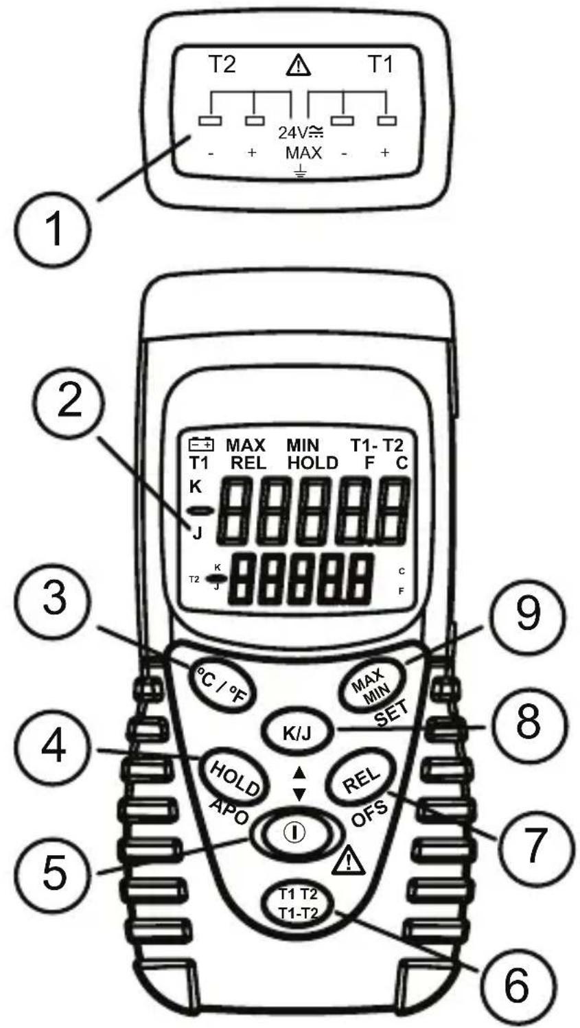
① T1 and T2 thermocouple inputs
② LCD
③ °C / °F temperature scales
④ Data HOLD
APO, turns off Auto Power Off
⑤ Power ON /OFF
⑥ T1, T2, T1-T2
⑦ RELative function OFS, Offset Thermocouple function
⑧ K / J thermocouple types
9 MAX MIN
SET command to save Thermal
Offset adjustment
CoNTENTS
Symbols....5
Unpacking and Inspection .... 5
Introduction ....5
Operation 5
°C / °F 6
MAX, MIN and AVG 6
K/J....6
HOLD 6
REL 6
T1 T2 / T1-T2 7
Auto Power Off (APO) 7
Thermocouple Error Correction (OFS, Offset) 7
Specifications 8
Maintenance and Repair 9
Battery Replacement 9
SYMBOLS
 | Refer to the manual |  | Complies with EU directives |
 | Conforms to relevant Australian standards. |  | Do not dispose of this product as unsorted municipal waste. |
⚠ Warning and Precautions
The bead thermocouples supplied with the meter are not intended for • contact with liquids or electrical circuits.
Do not mix thermocouple types.
Match the polarity of the adapter to the polarity of the thermocouple • inputs.
UNPACKING AND INSPECTION
Your shipping carton should include:
1 TMD-10 temperature meter
2 K-type thermocouples
1 9 volt battery
1 Manual
If any of the items are damaged or missing, return the complete package to the place of purchase for an exchange.
INTRODUCTION
The TMD-10 is a dual input temperature measurement meter using Type K or Type J thermocouples.
OPERATION
Press the 1. Ⓐ button to turn power on or off
Set the Function Switch to °C or °F. 2.
Select thermocouple type (K / J) and connect the thermocouple(s) to the 3. T1 or T2 input.
Do not mix thermocouple types.
⚠️ Match the polarity of the adapter to the polarity of the thermocouple input.
Expose the thermocouple(s) to the temperature(s) to be measured. 4.
Read the LCD display. 5.
°C / °F
Press the irc C/F key to change from Celsius ( irc C) to Fahrenheit ( irc F) temperature scale.
This setting can not be changed when in the HOLD mode. The TMD-10 will auto save the temperature scale setting during shutdown.
MAX, MIN and AVG
Press the MAX MIN button to start the recording of the maximum, minimum, and average of all readings after the function is enabled. Pressing the MAX MIN button steps the top reading through the MAX, MIN, and AVG values. Press the MAX MIN button for > 1 second to disable the function.
The MAX, MIN or AVG reading is shown on the top display and the actual reading is shown on the bottom display for T1.
To use MAX, MIN, and AVG for T2, disable MAX, MIN, and AVG and press and hold 1-T2 key > 1 sec to swap T2 to the top display and T1 to bottom display.
Press MAX MIN button again to activate the function.
If the TMD-10 turns off because of Auto Power Off, the recorded values will be saved for use when the meter is re-energized.
K/J
Press K/J key to switch T1 from type K to type J thermocouple for the top display.
Press and hold 1-T2 key > 1 sec to swap T2 to the top display and T1 to bottom display.
Press K/J key to switch T2 from type K to type J.
Press and hold 1-T2 key > 1 sec to swap T1 to the top display and T2 to bottom display.
This setting cannot be changed if in HOLD, MAX/MIN, T1-T2 or REL modes.
The TMD-10 will auto save the thermocouple type setting during shutdown.
HOLD
Press the HOLD key to freeze the LCD displays. Press the HOLD key again to return to normal operation. When the HOLD function is enabled, all function keys are disabled except for power ① key.
REL
Relative mode allows the user to offset the subsequent meter measurements with the top display reading as the reference value.
Press the REL button to enable the Relative function for the T1 thermocouple. The top display will reset to 0.0 (reference value) and subsequently readings display the difference between the reference value and the actual reading. The actual reading is shown on the bottom display. Press the REL button to disable the Relative function.
To use the Relative mode for T2, disable and press and hold key >1 second to swap T2 to the top display and T1 to bottom display.
T1 T2 / T1-T2
T1 T2 displays the 2 inputs independently. Press and hold T1-T2 button > 1 second to swap display location of the display location of T1 and T2.
(T1-T2)
Press T1-T2 button to display T1 minus T2 temperature value. The top display shows the T1-T2 temperature. The lower display shows the top display selected in the T1 T2 mode. Press T1-T2 button again to disable this function
Auto Power Off (APO)
The TMD-10 powers down automatically after approximately 15 minutes of inactivity to save battery life. Press the Ⓐ button to turn the TMD-10 ON. You can disable Auto Power Off by pressing the HOLD button > 1 second after the TMD-10 is ON.
⚠ The power cannot be turned OFF in the OFFSET SETUP mode.
Thermocouple Error Correction (OFS, Offset)
User can add an offset to compensate for the error of specific thermocouple probes.
Press and hold the 1REL (OFS) button > 1 second to enter the Offset Setup mode.
Immerse the thermocouple(s) in thermos bath with crushed ice and fresh 2. water (0.0 °C / 32.0 °F).
Press the 3.KJ button to increase or power Ⓐ button to decrease the Offset value. The allowable adjustment range is ±5 °C / ±9 °F in 0.1°C/°F increments.
Press 4 MAX MIN (SET) button to save and leave setup mode. The "Offset" icon will remain on the LCD.
Press and hold 5 T1 T2 button > 1 second to swap T2 to the top display and T1 to bottom display. Press KJ button to switch T2 from type K to type J.
Repeat steps 1, 2, 3 and 4 for T2. 6.
To remove the Offset, Repeat steps 1, 2, 3 and 4 setting the offset (lower 7. display) to 0.0. When both thermocouple offset are zeroed out, the "Offset" icon will be turned off.
SPECIFICATION
general
Display: Dual 5-digit LCD displays
Overrange indication:
"OL" stands for positive temperature
"-OL" stands for negative temperature.
Low battery: the “-+” sign will appear while battery is low.
Power Supply: 9V NEDA 1604, IEC 6F22, JIS 006P battery.
Battery life: approx. 200 hours.
Auto power off: approx. 15 minutes.
Environment: Indoor operation, - Altitude: Up to 2000 m.
Temperature / Humidity:
Operating: 0°C to 50°C (32°F to 122°F); < 80% RH
Storage: 0°C to 50°C (32°F to 122°F); < 80% RH
Dimensions: 130 x 56 x 38 mm (5.1 x 2.2 x 1.5 in.)
Weight: 170g(0.37 lb.) battery included
CE-EMC: EN61326-1 This product complies with requirements of the following European Community Directives: 89/336/EEC (Electromagnetic Compatibility) and 73/23/EEC (Low Voltage) as amended by 93/68/EEC (CE Marking). However, electrical noise or intense electromagnetic fields in the vicinity of the equipment may disturb the measurement circuit. Measuring instruments will also respond to unwanted signals that may be present within the measurement circuit. Users should exercise care and take appropriate precautions to avoid misleading results when making measurements in the presence of electronic interference.
Electrical (23 °C ± 5°C, < 80 % RH)
Temperature scale: °C or °F
Thermocouple type:
K-type: -200°C to 1370 °C (-328 °F to 2498 °F)
J-type: -200°C to 1050 °C (-328°F to 1922 °F)
Resolution: 0.1
Accuracy: ± (0.05 % rdg + 0.7 °C), ± (0.05 % rdg + 1.4 °F)
Input protection: 24V DC or AC.
Temperature Coefficient:
± (0.01 % rdg + 0.03 °C per °C); ± (0.01% rdg + 0.06 °F per °F) outside the specified + 18 °C to + 28 °C (+ 64°F to + 82°F) range.
Calibration: Yearly
MAINTENANCE AND REPAIR
If there appears to be a malfunction during the operation of the meter, the following steps should be performed in order to isolate the cause of the problem.
- Check the battery. Replace the battery immediately when the symbol “-+” appears on the LCD.
- Review the operating instructions for possible mistakes in operating procedure.
Except for the replacement of the battery, repair of the meter should be performed only by a Factory Authorized Service Center or by other qualified instrument service personnel. The front panel and case can be cleaned with a mild solution of detergent and water. Apply sparingly with a soft cloth and allow to dry completely before using. Do not use aromatic hydrocarbons or chlorinated solvents for cleaning.
bATTERy REPLACEMENT
- Turn off the meter and slide out the battery cover. Replace the battery with a NEDA type 1604 or equivalent 9V alkaline battery. Replace the cover.
- Remove battery when the TMD-10 is not used for extended period.

natural_image
Technical line drawing of a mechanical assembly with no visible text or symbolsBattery Replacement
AMPROBE®
TMD-10
© 2008 Amprobe Test Tools.
Amprobe Test Tools Amprobe Test Tools
Everett, WA 98203 Mississauga, ON L4Z 1X9
Tél : 877-993-5853 Tél : 905-890-7600
Fax:425-446-6390 Fax:905-890-6866
natural_image
Technical line drawing of a mechanical assembly with no visible text or symbols© 2008 Amprobe Test Tools.
Amprobe Test Tools Amprobe Test Tools
Everett, WA 98203 Mississauga, Ontario L4Z 1X9
Tel: 877-993-5853 Tel: 905-890-7600
Fax: 425-446-6390 Fax: 905-890-6866
natural_image
Technical line drawing of a mechanical assembly with multiple gears and a central 'OPEN' label (no text or symbols beyond the label)© 2008 Amprobe Test Tools.
Amprobe Test Tools Amprobe Test Tools
Everett, WA 98203 Mississauga, Ontario L4Z 1X9
Tel: 877-993-5853 Tel: 905-890-7600
Fax: 425-446-6390 Fax: 905-890-6866
MANUTENzloNE E RIPARAzloNI
natural_image
Technical line drawing of a mechanical assembly with no visible text or symbols©2008 Amprobe Test Tools.
Amprobe Test Tools Amprobe Test Tools
Everett, WA 98203 Mississauga, Ontario L4Z 1X9
Tel: 877-993-5853 Tel: 905-890-7600
Fax: 425-446-6390 Fax: 905-890-6866
natural_image
Technical line drawing of a mechanical assembly with no visible text or symbols© 2008 Amprobe Test Tools.
Med ensamrätt.
Amprobe Test Tools Amprobe Test Tools
Everett, WA 98203 Mississauga, ON L4Z 1X9
Tel: 877-993-5853 Tel: 905-890-7600
Fax: 425-446-6390 Fax: 905-890-6866
natural_image
Technical line drawing of a mechanical assembly with multiple gears and a central 'OPEN' label (no text or symbols beyond the label)Byte av batteri
Visit www.Amprobe.com for
Catalog•
Application notes•
Product specifications•
User manuals•


- AMPROBE®
- TMD-10
- Dual Temperature Meter
- Users Manual
- Limited Warranty and Limitation of Liability
- Repair
- In-Warranty Repairs and Replacement – All Countries
- Non-Warranty Repairs and Replacement – US and Canada
- Non-Warranty Repairs and Replacement – Europe
- CoNTENTS
- SYMBOLS
- ⚠ Warning and Precautions
- UNPACKING AND INSPECTION
- INTRODUCTION
- OPERATION
- Do not mix thermocouple types.
- ⚠️ Match the polarity of the adapter to the polarity of the thermocouple input.
- MAX, MIN and AVG
- HOLD
- REL
- T1 T2 / T1-T2
- Auto Power Off (APO)
- Thermocouple Error Correction (OFS, Offset)
- SPECIFICATION
- general
- MAINTENANCE AND REPAIR
- bATTERy REPLACEMENT
- MANUTENzloNE E RIPARAzloNI
Brand : Amprobe
Model : TMD-10
Category : Thermometer