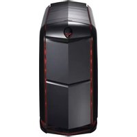
Aurora AAR4 - Desktop computer ALIENWARE - Free user manual and instructions
Find the device manual for free Aurora AAR4 ALIENWARE in PDF.


| Product Type | Desktop Computer |
| Brand | Alienware |
| Model | Aurora AAR4 |
| Dimensions (H x W x D) | 20.1 x 9.1 x 20.7 inches (510 x 230 x 525 mm) |
| Weight | Approximately 35 lbs (15.9 kg) |
| Power Supply | 875W or 1000W (depending on configuration) |
| Main Functions | High-performance gaming, VR-ready, customizable AlienFX lighting, overclocking support |
| Processor Options | Intel Core i5/i7 (e.g., i7-6700K) or AMD variants |
| Memory | Up to 32GB DDR4 (4 DIMM slots) |
| Storage Options | Up to 3 drives: SATA SSD + HDD, or PCIe NVMe SSD |
| Graphics Options | Single or dual NVIDIA GeForce GTX/RTX or AMD Radeon |
| Cooling System | Liquid cooling for CPU, front intake and top exhaust fans |
| Connectivity | USB 3.0, USB-C, HDMI, DisplayPort, Ethernet, Wi-Fi, Bluetooth |
| Operating System | Windows 10 Home/Pro |
| Front Panel Ports | 2x USB 3.0, headphone/mic, SD card reader (optional) |
| Expansion Slots | 2x PCIe x16, 1x PCIe x4, 1x M.2 |
| Security Features | Trusted Platform Module (TPM) 2.0, chassis intrusion switch, Kensington lock |
| Maintenance | Easy access to dust filters, tool-less drive bays, user-replaceable components |
| Repairability | Modular design, replaceable PSU, RAM, storage, GPU, CPU |
| Spare Parts Availability | Official parts from Dell/Alienware website, third-party compatible parts |
| Warranty | 1-year limited warranty (extendable) |
Frequently Asked Questions - Aurora AAR4 ALIENWARE
User questions about Aurora AAR4 ALIENWARE
0 question about this device. Answer the ones you know or ask your own.
Ask a new question about this device
Download the instructions for your Desktop computer in PDF format for free! Find your manual Aurora AAR4 - ALIENWARE and take your electronic device back in hand. On this page are published all the documents necessary for the use of your device. Aurora AAR4 by ALIENWARE.
USER MANUAL Aurora AAR4 ALIENWARE
Regulatory model: D01M
Regulatory type: D01M004
Notes, Cautions, and Warnings

NOTE: A NOTE indicates important information that helps you make better use of your product.

CAUTION: A CAUTION indicates either potential damage to hardware or loss of data, and tells you how to avoid the problem.

WARNING: A WARNING indicates a potential for property damage, personal injury, or death.
Information in this document is subject to change without notice.
© 2011 Dell Inc. All rights reserved.
Reproduction of these materials in any manner whatsoever without the written permission of Dell Inc. is strictly forbidden.
Trademarks used in this text: Dell™ and the DELL logo are trademarks of Dell Inc. Alienware® is a registered trademark of Alienware Corporation. Microsoft®, Windows®, and the Windows start button logo are either trademarks or registered trademarks of Microsoft Corporation in the United States and/or other countries.
Other trademarks and trade names may be used in this document to refer to either the entities claiming the marks and names or their products. Dell Inc. disclaims any proprietary interest in trademarks and trade names other than its own.
Contents
1 Before You Begin.... 13
Turn Off Your Computer and Connected Devices . . . . 13
Safety Instructions. 13
Recommended Tools.... 14
2 After Working Inside Your Computer.... 15
3 Technical Overview.... 17
Front View of Your Computer 17
Back View of Your Computer 18
Inside View of Your Computer. 19
System-Board Components 20
Master I/O Board Components 21
Top Lighting-Board Components 23
4 Left Side-Panel 25
Removing the Left Side-Panel 25
Replacing the Left Side-Panel. 27
5 Hard Drive(s) 29
Prerequisites....29
Removing the Hard Drive(s) 29
Replacing the Hard Drive(s) 30
Postrequisites 30
6 Hard-Drive Fan Assembly 33
Prerequisites 33
Removing the Hard-Drive Fan Assembly 33
Replacing the Hard-Drive Fan Assembly ..... 34
Postrequisites 35
7 Optical Drive(s) 37
Prerequisites 37
Removing the Optical Drive(s) 37
Replacing the Optical Drive(s). 38
Postrequisites 38
8 Media-Card Reader 41
Prerequisites....41
Removing the Media-Card Reader. 41
Replacing the Media-Card Reader 43
Postrequisites 44
9 PCI Shroud.... 45
Prerequisites. 45
Opening the PCI Shroud 45
Closing the PCI Shroud 46
Postrequisites 46
10 Drive-Bay Shroud 47
Prerequisites. 47
Removing the Drive-Bay Shroud 47
Replacing the Drive-Bay Shroud 48
Postrequisites 48
11 PCI-Express x1 Card 49
Prerequisites. 49
Removing the PCI-Express x1 Card 49
Replacing the PCI-Express x1 Card ..... 50
Postrequisites 51
12 PCI-Fan 53
Prerequisites. 53
Removing the PCI-Fan 53
Replacing the PCI-Fan 54
Postrequisites 55
13 Graphics Card 57
Prerequisites....57
Removing the Graphics Card. 57
Replacing the Graphics Card 58
Postrequisites 59
Installing Dual Graphic Cards 59
Connect the Display. 61
14 Memory Module(s).... 63
Prerequisites....63
Removing Memory Module(s) 63
Replacing Memory Module(s) 64
Postrequisites 66
15 Memory Fan.... 67
Prerequisites....67
Removing the Memory Fan. 67
Replacing the Memory Fan 68
Postrequisites 68
16 Processor Liquid-Cooling Assembly .... 71
Prerequisites. 71
Removing the Processor Liquid-Cooling Assembly. . . 71
Replacing the Processor Liquid-Cooling Assembly . . 72
Postrequisites 73
17 Processor 75
Prerequisites. 75
Removing the Processor. 75
Replacing the Processor 78
Postrequisites 80
18 Power-Supply Unit.... 83
Prerequisites. 83
Removing the Power-Supply Unit 83
Replacing the Power-Supply Unit. 86
Postrequisites 87
19 Coin-Cell Battery 89
Prerequisites. 89
Removing the Coin-Cell Battery 89
Replacing the Coin-Cell Battery. 90
Postrequisites 90
20 Theater-Lighting Batteries (ALX Chassis Only) 93
Prerequisites....93
Removing the Theater-Lighting Batteries ..... 93
Replacing the Theater-Lighting Batteries. 94
Postrequisites 94
21 System-Board Assembly 95
Prerequisites....95
Removing the System-Board Assembly ..... 95
Replacing the System-Board Assembly. 96
Postrequisites 97
Entering the Service Tag in BIOS 97
22 Master I/O Board 99
Prerequisites 99
Removing the Master I/O Board 99
Replacing the Master I/O Board....100
Postrequisites 100
23 Top Lighting-Board 103
Prerequisites. 103
Removing the Top Lighting-Board....103
Replacing the Top Lighting-Board. 104
Postrequisites 104
24 Right-Side Top Panel.... 107
Prerequisites. 107
Removing the Right-Side Top Panel. 107
Replacing the Right-Side Top Panel. 110
Postrequisites 111
25 Right-Side Middle Panel 113
Prerequisites. 113
Removing the Right-Side Middle Panel. 113
Replacing the Right-Side Middle Panel. 114
Postrequisites 115
26 Right Lighting-Board 117
Prerequisites. 117
Removing the Right Lighting-Board ..... 117
Replacing the Right Lighting-Board ..... 118
Postrequisites 119
27 Right-Side Bottom Panel 121
Prerequisites....121
Removing the Right-Side Bottom Panel ..... 121
Replacing the Right-Side Bottom Panel. 123
Postrequisites 124
28 Top Vent 125
Prerequisites....125
Removing the Top Vent 125
Replacing the Top Vent 127
Postrequisites 128
29 Front Bezel.... 129
Prerequisites....129
Removing the Front Bezel 129
Replacing the Front Bezel 131
Postrequisites 132
30 Back Bezel.... 133
Prerequisites. 133
Removing the Back Bezel 133
Replacing the Back Bezel 136
Postrequisites 136
31 WiFi/Bluetooth Assembly 137
Prerequisites. 137
Removing the WiFi/Bluetooth Card 137
Replacing the WiFi/Bluetooth Card ..... 138
Postrequisites 138
32 Top I/O Panel 141
Prerequisites. 141
Removing the Top I/O Panel 141
Replacing the Top I/O Panel. 142
Postrequisites 143
33 System Setup 145
Overview 145
Entering System Setup.... 145
System Setup Screens 145
System Setup Options 146
Boot Sequence 152
Clearing Forgotten Passwords. 154
Password: 155
155
Clearing CMOS Passwords 156
CMOS: 156
34 Flashing the BIOS 159
35 Specifications 161
Before You Begin
Turn Off Your Computer and Connected Devices

CAUTION: To avoid losing data, save and close all open files and exit all open programs before you turn off your computer.
1 Save and close all open files and exit all open programs.
2 Click Start and click Shut Down.
Microsoft Windows shuts down and then the computer turns off.

NOTE: If you are using a different operating system, see the documentation of your operating system for shut-down instructions.
3 Disconnect your computer and all attached devices from their electrical outlets.
4 Disconnect all telephone cables, network cables, and attached devices from your computer.
5 Press and hold the power button, while the computer is unplugged, to ground the system board.
Safety Instructions
Use the following safety guidelines to protect your computer from potential damage and ensure your personal safety.

WARNING: Before working inside your computer, read the safety information that shipped with your computer. For additional safety best practices information, see the Regulatory Compliance Homepage at dell.com/regulatory_compliance.

CAUTION: To avoid damaging the computer, ensure that the work surface is flat and clean.

CAUTION: To avoid damaging the components and cards, handle them by their edges and avoid touching pins and contacts.

WARNING: Disconnect all power sources before opening the computer cover or panels. After you finish working inside the computer, replace all covers, panels, and screws before connecting to the power source.
CAUTION: Only a certified service technician is authorized to remove the computer cover and access any of the components inside the computer. See the safety instructions for complete information about safety precautions, working inside your computer, and protecting against electrostatic discharge.
CAUTION: Before touching anything inside your computer, ground yourself by touching an unpainted metal surface, such as the metal at the back of the computer. While you work, periodically touch an unpainted metal surface to dissipate static electricity, which could harm internal components.
CAUTION: When you disconnect a cable, pull on its connector or on its pull-tab, not on the cable itself. Some cables have connectors with locking tabs or thumb-screws that you must disengage before disconnecting the cable. When disconnecting cables, keep them evenly aligned to avoid bending any connector pins. When connecting cables, ensure that the connectors and ports are correctly oriented and aligned.
CAUTION: To disconnect a network cable, first unplug the cable from your computer and then unplug the cable from the network device.
Recommended Tools
The procedures in this document may require the following tools:
- Small Phillips screwdriver
- H e x n u t d r i v e r
- Flash BIOS executable update program available at support.dell.com
After Working Inside Your Computer
After you complete replacement procedures, ensure the following:
- Replace all screws and ensure no stray screws remain inside your computer
- Connect any external devices, cables, cards, and any other part you removed before working on your computer
- Connect your computer and all attached devices to their electrical outlets

CAUTION: Before turning on your computer, replace all screws and ensure that no stray screws remain in the computer. Failure to do so may damage your computer.
- Turn on your computer.
Technical Overview

WARNING: Before working inside your computer, read the safety information that shipped with your computer and follow the steps in "Before You Begin" on page 13. For additional safety best practices information, see the Regulatory Compliance Homepage at dell.com/regulatory_compliance.
Front View of Your Computer

1 AlienHead/drive-panel open button 2 optical drive
3 optical-drive eject button 4 optical-drive bay
5 media-card reader/optical-drive bay 6 drive panel (open)
7 headphone connector 8 microphone connector
9 USB 3.0 connector 10 power button
11 USB 2.0 connectors (2)
Back View of Your Computer
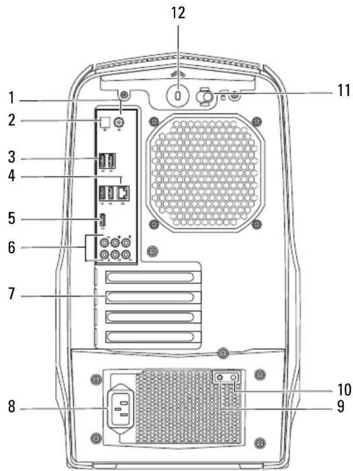
1 coaxial S/PDIF connector 2 optical S/PDIF connector
3 USB 2.0 connectors (4) 4 network connector and network lights
5 USB 3.0 connector 6 audio connectors
7 expansion-card slots 8 power connector
9 power-supply diagnostics button 10 power-supply diagnostics light
11 security-cable slot latch 12 security-cable slot
Inside View of Your Computer

1 memory module(s) 2 PCI-Express card(s)
3 optical drive(s) 4 hard-drive(s)
System-Board Components

1 heat-sink fan connector (SYS_FAN1)
3 memory-module connector (DIMM2)
5 processor socket (CPU1)
7 memory-module connector (DIMM3)
9 main power connector (PWR1)
11 heat-sink fan connector (SYS_FAN2)
13 CMOS jumper (CLEAR_CMOS)
15 serial ATA drive connectors (SATA3_4)
17 password jumper (PASSWORD)
19 USB connector (USB1)
21 USB connector (USB3)
23 front audio connector (FRONT_AUDIO)
25 PCI-Express x16 connector (SLOT3)
27 PCI-Express x16 connector (SLOT1)
2 memory-module connector (DIMM1)
4 processor power connector (PWR2)
6 memory-module connector (DIMM4)
8 processor fan connector (CPU_FAN)
10 front USB connector (FUSB3_0)
12 battery socket (BAT1)
14 serial ATA drive connectors (SATA1_2)
16 serial ATA drive connectors (SATA5_6)
18 front panel connector (FRONT_PANEL)
20 USB connector (USB2)
22 Low pin count debug header (LPC)
24 PCI-Express x1 connector (SLOT4)
26 PCI-Express x1 connector (SLOT2)
Master I/O Board Components

NOTE: The location of the connectors may vary based on the selections you made at the time of purchase.

flowchart
graph TD
    A["1"] --> B["2"]
    B --> C["3"]
    C --> D["4"]
    D --> E["5"]
    E --> F["6"]
    F --> G["7"]
    G --> H["8"]
    H --> I["9"]
    I --> J["10"]
    J --> K["11"]
    K --> L["12"]
    L --> M["13"]
    M --> N["14"]
    N --> O["15"]
    O --> P["16"]
    P --> Q["17"]
    Q --> R["18"]
    R --> S["19"]
    S --> T["20"]
    T --> U["21"]
1 FlexBay connector (FLEXBAY)
3 AlienHead connector (HEAD1)
5 left side-panel contact board connector (SIDE_L)
7 power-LED board connector (BLINK)
2 drive-bay shroud battery connector (FRONT_BEZEL)
4 PCI-fan connector (FAN_PCI)
6 WiFi/Bluetooth connector (BLUETOOTH)
8 wireless connector (WIRELESS)
9 hard-drive LED connector (HDD_LED1)
11 USB connector (MB_USB)
13 system-board lighting (MB_MIO)
15 right side-panel connector (SIDE_R)
17 ODD LED connector (ODD_LED)
19 Debug connector (DEBUG)
21 graphics-pump connector (GFX_PUMP)
10 hard-drive LED connector (HDD_LED2)
12 main-power connector (PWR1)
14 hard-drive fan connector (FAN_HDD)
16 ODD sensors (ODD_SW)
18 front-default connector (FACTORY_DEFAULT)
20 graphics-temperature sensor connector (GFX_TEMP)
Top Lighting-Board Components

1 System fan connector (SYS FAN)
3 Temperature sensor connector (TEMP SENSOR)
5 CPU pump connector (CPU PUMP)
2 CPU fan connector (CPU FAN)
4 Memory fan connector (MEM FAN)
Left Side-Panel

WARNING: Before working inside your computer, read the safety information that shipped with your computer and follow the steps in "Before You Begin" on page 13. For additional safety best practices information, see the Regulatory Compliance Homepage at dell.com/regulatory_compliance.

CAUTION: Ensure that sufficient space exists to support the computer with the computer cover removed—at least 30 cm (1 ft.) of desk top space.
Removing the Left Side-Panel

NOTE: Ensure that you remove the security cable from the security cable slot (if applicable).
1 Slide the security-cable slot latch to the unlocked position.
2 Lift the release panel to open the left side-panel.
3 Pull and lift the left side-panel away from the chassis.

NOTE: Theater lighting (available only in ALX chassis) turns on automatically when the left side-panel is removed.

1 release panel 2 security-cable slot
3 security-cable slot latch 4 left side-panel
Replacing the Left Side-Panel
1 Align the tabs on the left side-panel with the slots on the left side of the computer and push the panel to lock it in place.
2 Slide the security-cable slot latch to locked position.
3 Follow the steps in "After Working Inside Your Computer" on page 15.
Hard Drive(s)

WARNING: Before working inside your computer, read the safety information that shipped with your computer and follow the steps in "Before You Begin" on page 13. For additional safety best practices information, see the Regulatory Compliance Homepage at dell.com/regulatory_compliance.

WARNING: If you remove the hard drive from the computer when the drive is hot, do not touch the metal housing of the hard drive.

CAUTION: To avoid data loss, do not remove the hard drive while the computer is on or in Sleep state.

CAUTION: Hard drives are extremely fragile. Exercise care when handling the hard drive.
Prerequisites
1 Remove the left side-panel. See "Removing the Left Side-Panel" on page 25.
Removing the Hard Drive(s)
1 Press the release tabs to release the hard drive assembly from the computer.
2 Slide and remove the hard drive from the hard-drive cage.

NOTE: Repeat steps 1 and 2 to remove any other installed hard drives.

1 release tabs (2) 2 hard-drive
3 hard-drive cage
Replacing the Hard Drive(s)
1 Slide the hard drive into the hard-drive cage until the release tabs snap into place.
Postrequisites
1 Replace the left side-panel. See "Replacing the Left Side-Panel" on page 27.
2 Follow the steps in "After Working Inside Your Computer" on page 15.
Hard-Drive Fan Assembly

WARNING: Before working inside your computer, read the safety information that shipped with your computer and follow the steps in "Before You Begin" on page 13. For additional safety best practices information, see the Regulatory Compliance Homepage at dell.com/regulatory_compliance.

WARNING: The heat sink may be very hot during normal operation. Provide sufficient time for the heat-sink to cool before you touch it.
Prerequisites
1 Remove the left side-panel. See "Removing the Left Side-Panel" on page 25.
Removing the Hard-Drive Fan Assembly
1 Open the PCI shroud. See "Opening the PCI Shroud" on page 45.
2 Remove the drive-bay shroud. See "Removing the Drive-Bay Shroud" on page 47.

NOTE: Be careful not to damage the hard-drive fan cable while lifting the hard-drive fan assembly.
3 Carefully slide the hard-drive fan assembly out of the hard-drive fan assembly bay.
4 Note the routing of the hard-drive fan cable and then disconnect the hard-drive fan cable from the FAN_IIDD connector on the master I/O board.
5 Lift the hard-drive fan assembly out of the chassis.

1 hard-drive fan cable 2 hard-drive fan assembly
Replacing the Hard-Drive Fan Assembly
1 Slide the hard-drive fan assembly into the hard-drive fan assembly bay.
2 Route the cable through the slot in the hard-drive bay and then connect the hard-drive fan assembly cable to the FAN_HDD connector on the master I/O board.
3 Replace the drive-bay shroud. See "Replacing the Drive-Bay Shroud" on page 48.
4 Close the PCI shroud. See "Closing the PCI Shroud" on page 46.
Postrequisites
1 Replace the left side-panel. See "Replacing the Left Side-Panel" on page 27.
2 Follow the steps in "After Working Inside Your Computer" on page 15.
Optical Drive(s)

WARNING: Before working inside your computer, read the safety information that shipped with your computer and follow the steps in "Before You Begin" on page 13. For additional safety best practices information, see the Regulatory Compliance Homepage at dell.com/regulatory_compliance.
Prerequisites
1 Remove the left side-panel. See "Removing the Left Side-Panel" on page 25.
Removing the Optical Drive(s)
1 Press the AlienHead on the front of your computer to lower the drive panel.
2 Disconnect the data cable and power cable from the optical drive.
3 Lift the securing tab, and holding the tab in place, push and slide the optical drive out through the front of the computer.

1 power cable 2 data cable
3 securing tab 4 optical drive
Replacing the Optical Drive(s)
1 Lift and hold the securing tab, and then slide the optical drive through the front of the computer until the securing tab snaps into place.
2 Connect the power cable and the data cable to the optical drive.
3 Lift the drive panel towards the top of your computer until it snaps into place.
Postrequisites
1 Replace the left side-panel. See "Replacing the Left Side-Panel" on page 27.
2 Follow the steps in "After Working Inside Your Computer" on page 15.
Media-Card Reader

WARNING: Before working inside your computer, read the safety information that shipped with your computer and follow the steps in "Before You Begin" on page 13. For additional safety best practices information, see the Regulatory Compliance Homepage at dell.com/regulatory_compliance.
Prerequisites
1 Remove the left side-panel. See "Removing the Left Side-Panel" on page 25.
Removing the Media-Card Reader
1 Press the AlienHead on the front of your computer to lower the drive panel.
2 Open the PCI shroud. See "Opening the PCI Shroud" on page 45.
3 Disconnect the FlexBay USB cable from the FLEXBAY connector on the master I/O board. For more information on the location of the connector, see "Master I/O Board Components" on page 21.
4 Lift and hold the securing tab and then push the FlexBay dock to slide it out through the front of the computer.

1 FlexBay USB cable 2 securing tab
3 FlexBay dock 4 Master I/O board
5 FlexBay USB cable-connector
5 Remove the screws that secure the media-card reader to the FlexBay dock.
6 Slide the media-card reader out of the FlexBay dock.

1 media-card reader 2 screws (4)
3 FlexBay dock
Replacing the Media-Card Reader
1 Slide the media-card reader into the FlexBay dock.
2 Replace the screws that secure the media-card reader to the FlexBay dock.
3 Lift the securing tab and slide the FlexBay dock through the front of the computer until the securing tab snaps into place.
4 Connect the FlexBay USB cable to the FLEXBAY connector on the master I/O board. For more information on the location of the connector, see "Master I/O Board Components" on page 21.
5 Close the PCI shroud. See "Closing the PCI Shroud" on page 46.
6 Replace the left side-panel. See "Replacing the Left Side-Panel" on page 27.
7 Lift the drive panel towards the top of your computer until it snaps into place.
Postrequisites
1 Replace the left side-panel. See "Replacing the Left Side-Panel" on page 27.
2 Follow the steps in "After Working Inside Your Computer" on page 15.
PCI Shroud

WARNING: Before working inside your computer, read the safety information that shipped with your computer and follow the steps in "Before You Begin" on page 13. For additional safety best practices information, see the Regulatory Compliance Homepage at dell.com/regulatory_compliance.
Prerequisites
1 Remove the left side-panel. See "Removing the Left Side-Panel" on page 25.
Opening the PCI Shroud
1 Press the shroud-release button and rotate the PCI shroud away from the chassis.
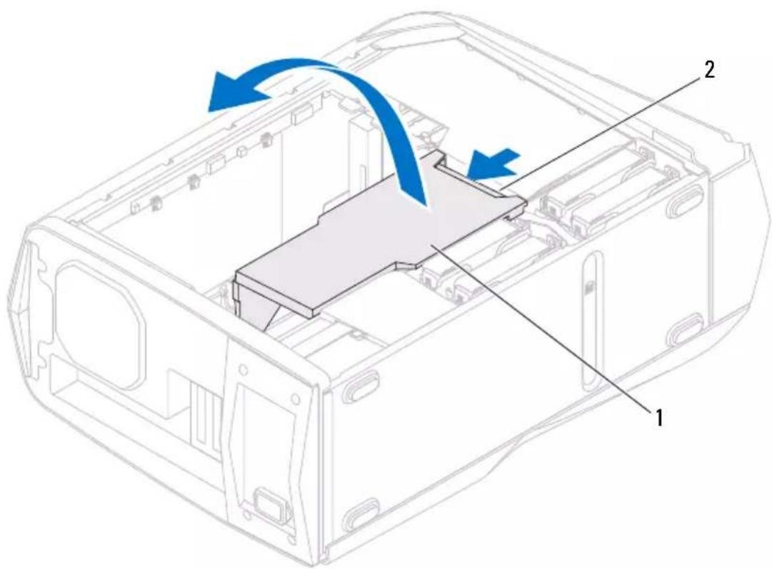
1 PCI shroud 2 shroud-release button
Closing the PCI Shroud
1 Lower the PCI shroud into the chassis and press down until it snaps into position.
Postrequisites
1 Replace the left side-panel. See "Replacing the Left Side-Panel" on page 27.
2 Follow the steps in "After Working Inside Your Computer" on page 15.
Drive-Bay Shroud

WARNING: Before working inside your computer, read the safety information that shipped with your computer and follow the steps in "Before You Begin" on page 13. For additional safety best practices information, see the Regulatory Compliance Homepage at dell.com/regulatory_compliance.
Prerequisites
1 Remove the left side-panel. See "Removing the Left Side-Panel" on page 25.
2 Open the PCI shroud. See "Removing the Drive-Bay Shroud" on page 47.
Removing the Drive-Bay Shroud

NOTE: Be careful not to damage the cable connected to the drive-bay shroud while sliding the drive-bay shroud.
1 Press the tabs and slide the drive-bay shroud towards the back of the chassis.
2 Gently turn the drive-bay shroud over and place it on the chassis.

1 tabs (2) 2 drive-bay shroud
Replacing the Drive-Bay Shroud
1 Align the drive-bay shroud with the slots on the chassis.
2 Slide the drive-bay shroud toward the front of the chassis until it clicks into place.
Postrequisites
1 Replace the left side-panel. See "Replacing the Left Side-Panel" on page 27.
2 Follow the steps in "After Working Inside Your Computer" on page 15.
3 Close the PCI shroud. See "Closing the PCI Shroud" on page 46.
PCI-Express x1 Card
WARNING: Before working inside your computer, read the safety information that shipped with your computer and follow the steps in "Before You Begin" on page 13. For additional safety best practices information, see the Regulatory Compliance Homepage at dell.com/regulatory_compliance.
Prerequisites
1 Remove the left side-panel. See "Removing the Left Side-Panel" on page 25.
2 Open the PCI shroud. See "Opening the PCI Shroud" on page 45.
Removing the PCI-Express x1 Card
1 Locate the PCI-Express xl card on the system board. See "System-Board Components" on page 20.
2 Disconnect any cables connected to the card (if applicable).
3 Remove the screw that secures the card to the chassis.
4 Grasp the card by its top corners and ease it out of the connector.
NOTE: For removing a PCI-Express x16 card, see "Removing the Graphics Card" on page 57.
NOTE: If you are not replacing a card, install a filler bracket in the empty card-slot opening.

1 screw 2 PCI-Express x1 card
3 PCI-Express x1 connector
Replacing the PCI-Express x1 Card
1 Remove the screw that secures the filler bracket and remove the filler bracket (if applicable).

1 screw 2 filler bracket
2 Align the PCI-Express x1 card with the PCI-Express x1 card connector on the system board.
3 Place the card in the connector and press down firmly. Ensure that the card is firmly seated.
4 Connect any required cables to the card. For information on the cables to be connected to the card, see the documentation that shipped with the card.
5 Replace the screw that secures the card to the chassis.
Postrequisites
1 Close the PCI shroud. See "Closing the PCI Shroud" on page 46.
2 Replace the left side-panel. See "Replacing the Left Side-Panel" on page 27.
3 Follow the steps in "After Working Inside Your Computer" on page 15.
PCI-Fan

WARNING: Before working inside your computer, read the safety information that shipped with your computer and follow the steps in "Before You Begin" on page 13. For additional safety best practices information, see the Regulatory Compliance Homepage at dell.com/regulatory_compliance.

WARNING: The heat sink may be very hot during normal operation. Provide sufficient time for the heat-sink to cool before you touch it.
Prerequisites
1 Remove the left side-panel. See "Removing the Left Side-Panel" on page 25.
Removing the PCI-Fan
1 Open the PCI shroud. See "Opening the PCI Shroud" on page 45.
2 Remove the drive-bay shroud. See "Removing the Drive-Bay Shroud" on page 47.
3 Disconnect the PCI-fan cable from the FAN_PCI connector on the master I/O board.
4 Press the tabs and lift the PCI-fan out of the metal brackets on the chassis.
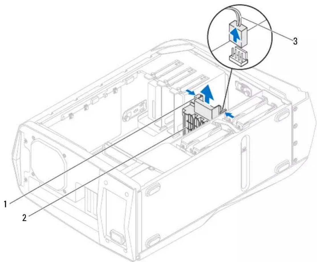
1 tabs (2) 2 PCI-fan
3 PCI-fan cable
Replacing the PCI-Fan
1 Align the PCI-fan with the metal brackets on the chassis.
2 Slide the PCI-fan into the chassis.
3 Connect the PCI-fan cable to the FAN_PCI connector on the master I/O board.
4 Replace the drive-bay shroud. See "Replacing the Drive-Bay Shroud" on page 48.
5 Close the PCI shroud. See "Closing the PCI Shroud" on page 46.
Postrequisites
1 Replace the left side-panel. See "Replacing the Left Side-Panel" on page 27.
2 Follow the steps in "After Working Inside Your Computer" on page 15.
Graphics Card

WARNING: Before working inside your computer, read the safety information that shipped with your computer and follow the steps in "Before You Begin" on page 13. For additional safety best practices information, see the Regulatory Compliance Homepage at dell.com/regulatory_compliance.
The system board of your computer is equipped with two PCI-Express x16 connectors to install graphic card(s). To locate the PCI-Express x16 connectors on the system board, see "System-Board Components" on page 20.
Prerequisites
1 Remove the left side-panel. See "Removing the Left Side-Panel" on page 25.
2 Open the PCI shroud. See "Opening the PCI Shroud" on page 45.
Removing the Graphics Card
1 Locate the graphics card (PCI-Express x16 card) on the system board. See "System-Board Components" on page 20.

NOTE: The location of the power-cable connectors on your graphics card may vary.
2 Press the releasing clips on the power-cable connectors and disconnect the power cables from the graphics card.
3 Remove the screws that secure the graphics card to the chassis.
4 Press and hold the securing tab on the card connector, grasp the card by its top corners, and then ease the card out of the card connector.
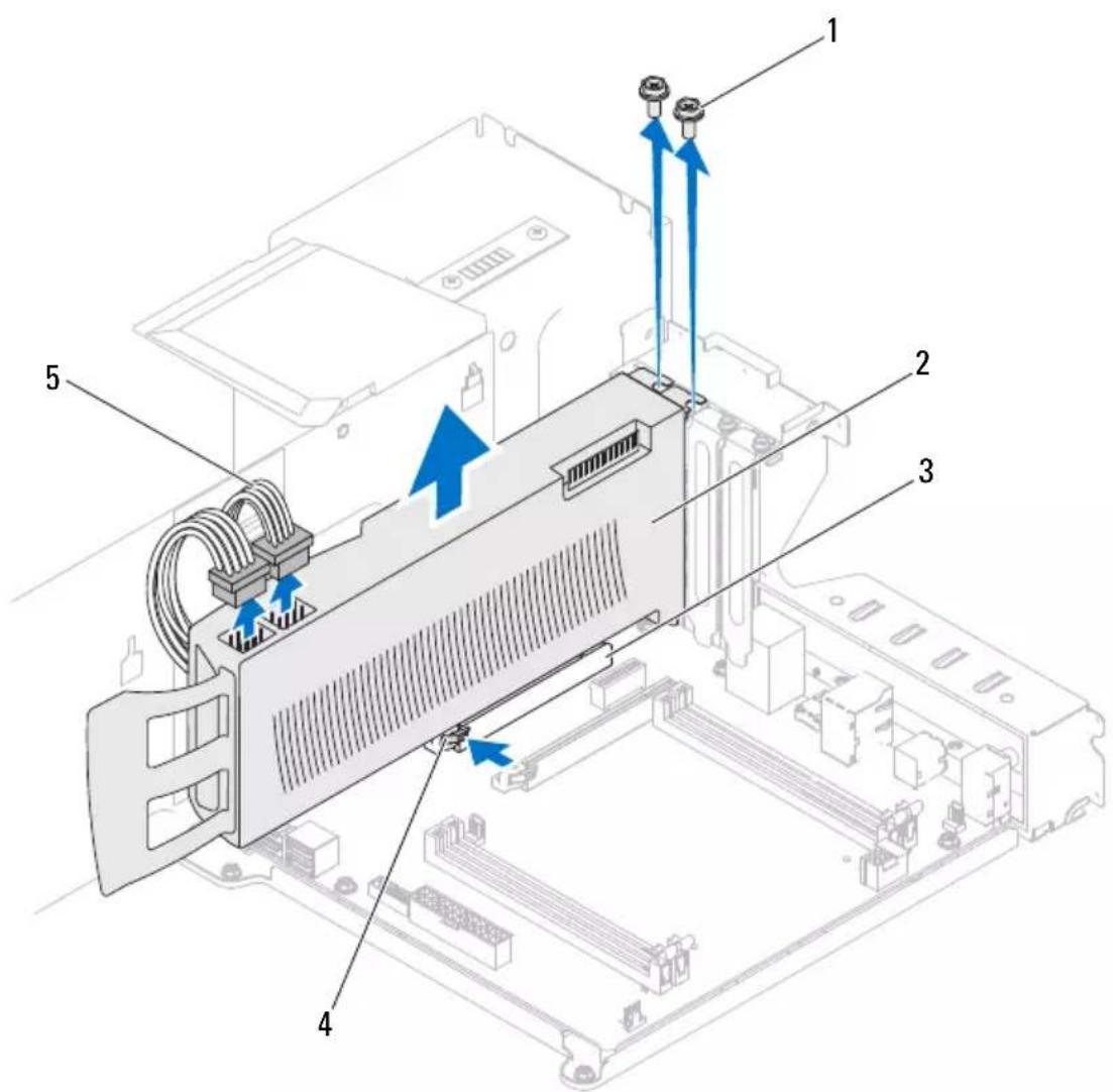
1 screws (2) 2 graphics card
3 PCI-Express x16 connector 4 securing tab
5 power cables (2)
Replacing the Graphics Card
1 Align the graphics card with the PCI-Express x16 card connector on the system board.
2 Place the card in the connector and press down firmly. Ensure that the card is firmly seated.
3 Replace the screws that secure the graphics card to the chassis.
4 Connect the power cables to the graphics card.
Postrequisites
1 Close the PCI shroud. See "Closing the PCI Shroud" on page 46.
2 Replace the left side-panel. See "Replacing the Left Side-Panel" on page 27.
3 Follow the steps in "After Working Inside Your Computer" on page 15.
Installing Dual Graphic Cards
1 Locate the second PCI-Express x16 connector on the system board. See "System-Board Components" on page 20.
2 Align the second graphics card with the second PCI-Express x16 card connector on the system board.
3 Place the card in the connector and press down firmly. Ensure that the card is firmly seated in the slot.
4 Replace the screws that secure the second graphics card to the chassis.
5 Connect the dual graphics bridge connecting the two graphics card.
6 Connect the two power cables to the graphics card.

1 power cables (2) 2 Dual graphics bridge
3 screws (2) 4 PCI-Express x16 card
5 PCI-Express x16 connector
7 Close the PCI shroud. See "Closing the PCI Shroud" on page 46.
8 Replace the left side-panel. See "Replacing the Left Side-Panel" on page 27.
9 Follow the steps in "After Working Inside Your Computer" on page 15.
Connect the Display
If your computer has dual graphics cards, connect the display to the connectors on the primary graphics card.

1 primary graphic-card connectors
2 secondary graphic-card connectors
Memory Module(s)

WARNING: Before working inside your computer, read the safety information that shipped with your computer and follow the steps in "Before You Begin" on page 13. For additional safety best practices information, see the Regulatory Compliance Homepage at dell.com/regulatory_compliance.
Prerequisites
1 Remove the left side-panel. See "Removing the Left Side-Panel" on page 25.
2 Open the PCI shroud. See "Opening the PCI Shroud" on page 45.
Removing Memory Module(s)

WARNING: The memory module(s) may become very hot during normal operation. Allow the memory module(s) to cool before touching them.
1 Push the securing clip away from the memory module.
2 Grasp the memory module near the securing clip, and then gently ease the memory module out of the memory-module connector.

1 securing clip 2 memory-module connector
Replacing Memory Module(s)
CAUTION: If the memory module is not installed correctly, your computer may not boot.
CAUTION: If you remove the original memory module(s) from your computer during a memory upgrade, keep them separate from any new module(s) that you may have, even if you purchased the new module(s) from Dell. If possible, do not pair an original memory module with a new memory module. Otherwise, your computer may not start properly. The recommended memory configurations are: matched memory modules installed in DIMM connectors 1 and 2 and another matched memory modules installed in DIMM connectors 3 and 4.

Recommended memory configuration:
Type Slots
1333 MHz, 1600 MHz, and 1866 MHz DDR3 Slots 1 and 2 or slots 1 through 4
1 Align the notch on the bottom of the memory module with the tab on the memory-module connector.

1 cutouts (2) 2 memory module
3 notch 4 tab

CAUTION: To avoid damage to the memory module, first insert the end away from the securing clip and then insert the end near the securing clip.
2 Insert the memory module into the memory-module connector until the memory module snaps into position and the securing clip locks in place.
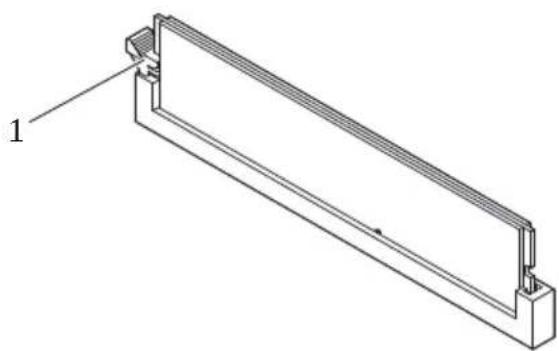
natural_image
Technical line drawing of a rectangular mechanical component with a labeled part (1), no text or symbols present.1 securing clip (snapped in position)
Postrequisites
1 Close the PCI shroud. See "Closing the PCI Shroud" on page 46.
2 Replace the left side-panel. See "Replacing the Left Side-Panel" on page 27.
3 Follow the steps in "After Working Inside Your Computer" on page 15.
Memory Fan

WARNING: Before working inside your computer, read the safety information that shipped with your computer and follow the steps in "Before You Begin" on page 13. For additional safety best practices information, see the Regulatory Compliance Homepage at dell.com/regulatory_compliance.

WARNING: The heat sink may be very hot during normal operation. Provide sufficient time for the heat-sink to cool before you touch it.
Prerequisites
1 Remove the left side-panel. See "Removing the Left Side-Panel" on page 25.
Removing the Memory Fan
1 Disconnect the memory fan cable from the MEM_FAN connector on the top lighting-board.
2 Pull the release tab towards the bottom of the computer and lift the memory fan out of the chassis.

1 memory fan 2 tab
3 memory-fan cable 4 top lighting-board
Replacing the Memory Fan
1 Align the tabs on the memory fan with the slots on the computer chassis and slide the fan until it snaps into position.
2 Connect the memory fan cable to the MEM_FAN connector on the top lighting-board.
Postrequisites
1 Replace the left side-panel. See "Replacing the Left Side-Panel" on page 27.
2 Follow the steps in "After Working Inside Your Computer" on page 15.
Processor Liquid-Cooling Assembly

WARNING: Before working inside your computer, read the safety information that shipped with your computer and follow the steps in "Before You Begin" on page 13. For additional safety best practices information, see the Regulatory Compliance Homepage at dell.com/regulatory_compliance.
Prerequisites
1 Remove the left side-panel. See "Removing the Left Side-Panel" on page 25.
2 Open the PCI shroud. See "Opening the PCI Shroud" on page 45.
Removing the Processor Liquid-Cooling Assembly

WARNING: Despite having a plastic shield, the processor liquid-cooling assembly may be very hot during normal operation. Ensure that it has had sufficient time to cool before you touch it.

CAUTION: To ensure maximum cooling for the processor, do not touch the heat transfer areas on the processor liquid-cooling assembly. The oils in your skin can reduce the heat transfer capability of the thermal grease.
1 Press the tab on the CPU pump cable and disconnect the cable from the top lighting-board.
2 Disconnect the system fan cable from the top lighting-board.
3 Loosen the captive screws that secure the processor liquid-cooling assembly to the system board.
4 Remove the screws that secure the processor liquid-cooling assembly to the chassis.
5 Slide and lift the processor liquid-cooling assembly out of the chassis.

1 screws (4) 2 processor liquid-cooling assembly
3 top lighting-board 4 CPU-pump cable
5 captive screws (4) 6 system-fan cable
Replacing the Processor Liquid-Cooling Assembly

CAUTION: Incorrect alignment of the processor liquid-cooling assembly can damage the system board and processor.
1 Align the screw holes on the processor liquid-cooling assembly with the screw holes on the chassis.
2 Replace the screws that secure the processor liquid-cooling assembly to the chassis.
NOTE: The original thermal grease can be reused if the original processor and processor liquid-cooling assembly are reinstalled together. If either the processor or the processor liquid-cooling assembly is replaced, use the thermal grease provided in the kit to ensure that thermal conductivity is achieved.
3 Apply thermal grease between the processor liquid-cooling assembly and the processor.
4 Tighten the captive screws that secure the processor liquid-cooling assembly to the system board.
5 Connect the system fan cable and the CPU pump cable to the connectors on the top lighting-board.

Postrequisites
1 Close the PCI shroud. See "Closing the PCI Shroud" on page 46.
2 Replace the left side-panel. See "Replacing the Left Side-Panel" on page 27.
3 Follow the steps in "After Working Inside Your Computer" on page 15.
Processor

CAUTION: Before working inside your computer, read the safety information that shipped with your computer and follow the steps in "Before You Begin" on page 13. For additional safety best practices information, see the Regulatory Compliance Homepage at dell.com/regulatory_compliance.
Prerequisites
1 Remove the left side-panel. See "Removing the Left Side-Panel" on page 25.

WARNING: Despite having a plastic shield, the processor liquid-cooling assembly may be very hot during normal operation. Ensure that it has had sufficient time to cool before you touch it.
2 Remove the processor liquid-cooling assembly. See "Removing the Processor Liquid-Cooling Assembly" on page 71.
Removing the Processor
1 Press down and push the release lever away from the processor to release it from the securing tab.
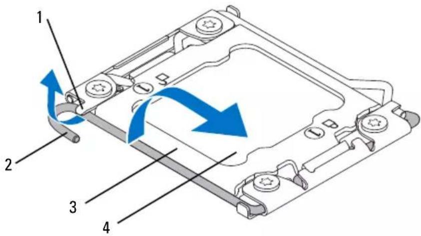
1 securing tab 2 release lever
3 processor cover 4 processor
2 Press down and push the release lever away from the processor to release it from the securing tab.
3 Extend this release lever completely to open the processor cover.

1 processor cover 2 processor 3 securing tab 4 release lever
CAUTION: When removing the processor, do not touch any of the pins inside the socket or allow any objects to fall on the pins in the socket.
4 Open the processor cover and gently lift the processor from the processor socket.
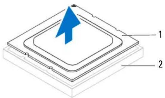
1 processor 2 processor socket
Replacing the Processor
1 Ensure that the second release lever is fully extended in the open position.

CAUTION: You must position the processor correctly in the processor socket to avoid damage to the processor.
2 Align the pin-1 corner of the processor with the pin-1 corner of the processor socket, and then place the processor in the processor socket.

1 processor pin-1 indicator 2 processor
3 alignment notches (4) 4 alignment tabs (4)
5 processor socket
3 When the processor is fully seated in the socket, close the processor cover.
4 Pivot the release lever down and place it under the tab on the processor cover.

1 processor cover 2 processor
3 securing tabs 4 release levers
5 Pivot the release lever down and place it under the tab on the processor cover.

1 securing tabs 2 processor cover
3 release levers 4 processor
Postrequisites
1 Replace the processor liquid-cooling assembly. See "Replacing the Processor Liquid-Cooling Assembly" on page 72.
2 Replace the left side-panel. See "Replacing the Left Side-Panel" on page 27.
3 Follow the steps in "After Working Inside Your Computer" on page 15.
Power-Supply Unit

WARNING: Before working inside your computer, read the safety information that shipped with your computer and follow the steps in "Before You Begin" on page 13. For additional safety best practices information, see the Regulatory Compliance Homepage at dell.com/regulatory_compliance.
Prerequisites
1 Remove the left side-panel. See "Removing the Left Side-Panel" on page 25.
Removing the Power-Supply Unit
1 Lift and hold the tab on the power-supply cover, slide the power-supply cover towards the back of the chassis, and remove the power-supply cover.
2 Lift the power-supply cover away from the chassis.

1 power-supply cover 2 tab
3 Press the securing clips on the DC-wire harness and disconnect the DC-wire harness from the power-supply unit.
4 Loosen the captive screws that secure the power-supply unit to the back of the chassis.
5 Slide the power-supply unit out through the back of the chassis.
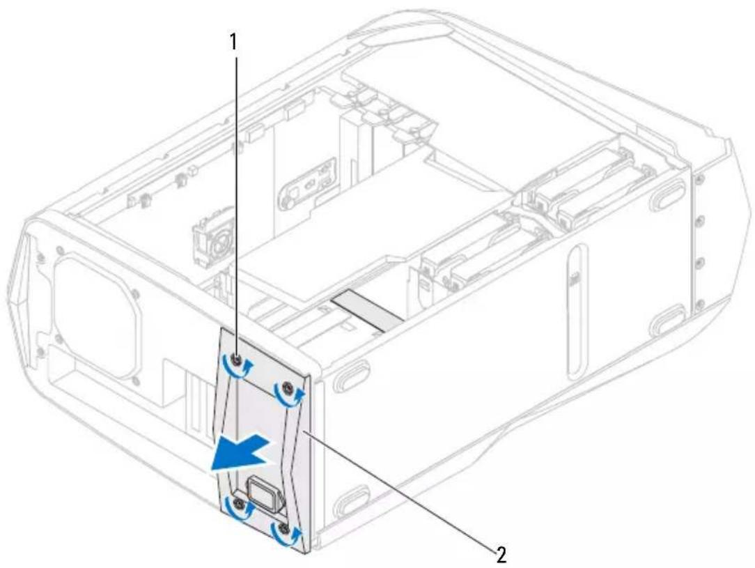
1 captive screws (4) 2 power-supply unit
6 Remove the screws that secure the power-supply unit to the bezel.
7 Remove the bezel from the power-supply unit.

1 bezel 2 power-supply unit
3 screws (4)
Replacing the Power-Supply Unit
1 Align the screw holes on the power-supply unit with the screw holes on the bezel.
2 Replace the screws that secure the power-supply unit to the bezel.
3 Slide the power-supply unit into the chassis through the back of the computer.
4 Tighten the captive screws that secure the power-supply unit to the back of the chassis.
5 Connect the DC-wire harness to the power-supply unit.
6 Align the notch on the power-supply cover with the tab on the chassis.
7 Slide the power-supply cover towards the tabs until it locks in place.
Postrequisites
1 Replace the left side-panel. See "Replacing the Left Side-Panel" on page 27.
2 Follow the steps in "After Working Inside Your Computer" on page 15.
Coin-Cell Battery

WARNING: Before working inside your computer, read the safety information that shipped with your computer and follow the steps in "Before You Begin" on page 13. For additional safety best practices information, see the Regulatory Compliance Homepage at dell.com/regulatory_compliance.

WARNING: A battery may explode if installed incorrectly. Replace the battery only with the same or equivalent type. Discard used batteries according to the manufacturer's instructions.
Prerequisites
1 Remove the left side-panel. See "Removing the Left Side-Panel" on page 25.
2 Open the PCI shroud. See "Opening the PCI Shroud" on page 45.
3 Remove the PCI-Express xl card. See "Removing the PCI-Express xl Card" on page 49.
4 Remove the graphics card. See "Removing the Graphics Card" on page 57.
Removing the Coin-Cell Battery

CAUTION: Removing the coin-cell battery resets the BIOS settings to default. It is recommended that you note the BIOS settings before removing the coin-cell battery. See "System Setup" on page 145 for instructions on entering the system setup program.
1 Locate the battery socket. See "System-Board Components" on page 20.
2 Press the battery-release lever to remove the battery.

1 coin-cell battery 2 battery-release lever
Replacing the Coin-Cell Battery
1 Insert the battery into the socket with the side labeled + facing up and press down the battery in the socket.

natural_image
Diagram showing a circular component with an 'X' and a blue arrow inside a tray-like container (no text or symbols)Postrequisites
1 Replace the PCI-Express x1 card. See "Replacing the PCI-Express x1 Card" on page 50.
2 Replace the graphics card. See "Replacing the Graphics Card" on page 58.
3 Close the PCI shroud. See "Closing the PCI Shroud" on page 46.
4 Replace the left side-panel. See "Replacing the Left Side-Panel" on page 27.
5 Follow the steps in "After Working Inside Your Computer" on page 15.
6 Enter the system setup program and set the time and date. See "Entering System Setup" on page 145.
7 Update the BIOS settings with values you may have noted before replacing the coin-cell battery. See "System Setup" on page 145.
Theater-Lighting Batteries (ALX Chassis Only)

WARNING: Before working inside your computer, read the safety information that shipped with your computer and follow the steps in "Before You Begin" on page 13. For additional safety best practices information, see the Regulatory Compliance Homepage at dell.com/regulatory_compliance.
Prerequisites
1 Remove the left side-panel. See "Removing the Left Side-Panel" on page 25.
2 Open the PCI shroud. See "Opening the PCI Shroud" on page 45.
3 Remove the drive-bay shroud. See "Removing the Drive-Bay Shroud" on page 47.
Removing the Theater-Lighting Batteries
1 Turn the drive-bay shroud over.
2 Open the theater-lighting battery compartment door.
NOTE: Your computer ships with two AA rechargeable batteries.
3 Remove the two batteries from the theater-lighting battery compartment.


natural_image
Isometric technical diagram of a mechanical assembly with labeled components (1 and 2), showing internal structure and a blue directional arrow indicating motion or force.1 drive-bay shroud 2 theater-lighting battery-compartment door
Replacing the Theater-Lighting Batteries
1 Insert the two batteries in the theater-lighting battery compartment.
2 Close the theater-lighting battery-compartment door.
Postrequisites
1 Replace the drive-bay shroud. See "Replacing the Drive-Bay Shroud" on page 48.
2 Close the PCI shroud. See "Closing the PCI Shroud" on page 46.
3 Replace the left side-panel. See "Replacing the Left Side-Panel" on page 27.
4 Follow the steps in "After Working Inside Your Computer" on page 15.
System-Board Assembly

WARNING: Before working inside your computer, read the safety information that shipped with your computer and follow the steps in "Before You Begin" on page 13. For additional safety best practices information, see the Regulatory Compliance Homepage at dell.com/regulatory_compliance.
Prerequisites
1 Remove the left side-panel. See "Removing the Left Side-Panel" on page 25.
1 Remove the memory fan. See "Removing the Memory Fan" on page 67.
2 Open the PCI shroud. See "Opening the PCI Shroud" on page 45.
3 Remove the graphics card. See "Removing the Graphics Card" on page 57.
4 Remove the PCI-Express x1 card. See "Removing the PCI-Express x1 Card" on page 49.
5 Remove the coin-cell battery. See "Removing the Coin-Cell Battery" on page 89.
6 Remove the memory module(s). See "Memory Module(s)" on page 63.
7 Remove the processor liquid-cooling assembly. See "Removing the Processor Liquid-Cooling Assembly" on page 71.
8 Remove the processor. See "Removing the Processor" on page 75.
Removing the System-Board Assembly

NOTE: Your computer's service tag is stored in the system board. You must enter the service tag in the BIOS after you replace the system-board assembly.

NOTE: Before disconnecting the cables from the system board, note the location of the connectors, so that you can reconnect them correctly after you replace the system-board assembly.
1 Disconnect all the cables connected to the system-board assembly.
2 Remove the screws that secure the system-board assembly to the chassis.
3 Slide the system-board assembly towards the front of the chassis to disengage it from the latches that secure it to the chassis.
4 Lift the system-board assembly out of the chassis.
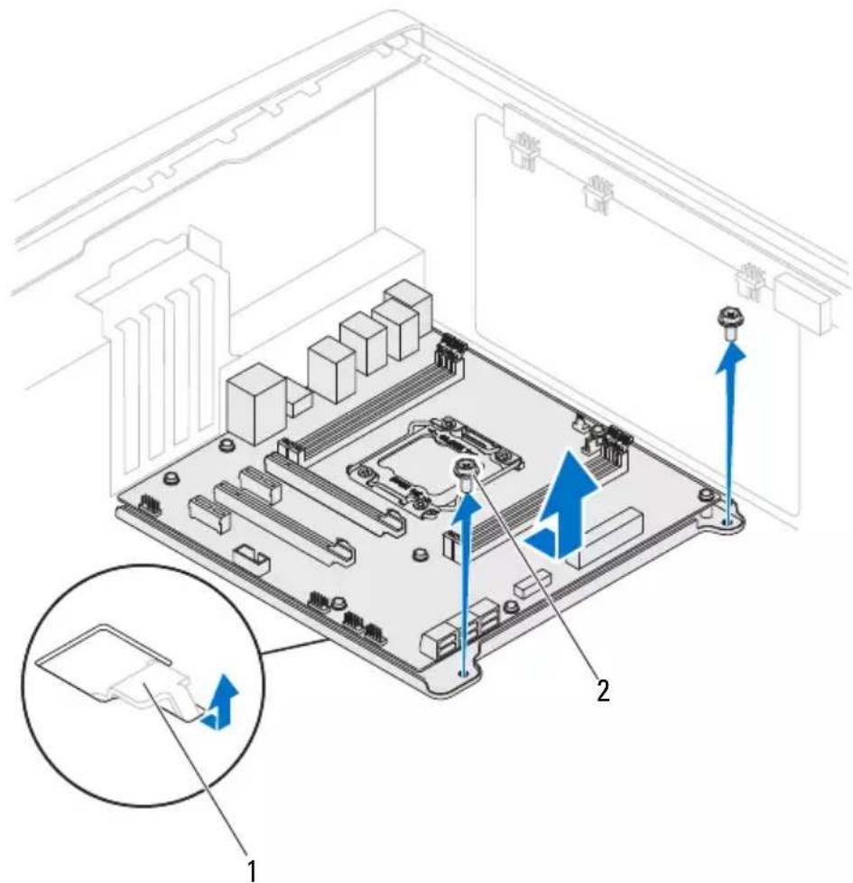
1 latch 2 screws (2)
Replacing the System-Board Assembly
1 Align the connectors on the system-board assembly with the slots on the chassis and place the system-board assembly in position.
2 Slide the system-board assembly towards the back of the chassis and engage the latches that secure it to the chassis.
3 Replace the screws that secure the system-board assembly to the chassis.
4 Route and connect the cables that you disconnected from the system-board assembly.

NOTE: For information on system board connectors, see "System-Board Components" on page 20.
Postrequisites
1 Replace the processor. See "Replacing the Processor" on page 78.
2 Replace the processor liquid-cooling assembly. See "Replacing the Processor Liquid-Cooling Assembly" on page 72.
3 Replace the memory module(s). See "Replacing Memory Module(s)" on page 64.
4 Replace the coin-cell battery. See "Replacing the Coin-Cell Battery" on page 90.
5 Replace the PCI-Express x1 card. See "Replacing the PCI-Express x1 Card" on page 50.
6 Replace the graphics card. See "Replacing the Graphics Card" on page 58.
7 Close the PCI shroud. See "Closing the PCI Shroud" on page 46.
8 Replace the memory fan. See "Replacing the Memory Fan" on page 68.
9 Replace the left side-panel. See "Replacing the Left Side-Panel" on page 27.
10 Follow the steps in "After Working Inside Your Computer" on page 15.
Entering the Service Tag in BIOS
1 Turn on the computer.
2 Press
3 Navigate to the main tab and enter the service tag in the Service Tag Setting field.
Master I/O Board

WARNING: Before working inside your computer, read the safety information that shipped with your computer and follow the steps in "Before You Begin" on page 13. For additional safety best practices information, see the Regulatory Compliance Homepage at dell.com/regulatory_compliance.
Prerequisites
1 Remove the left side-panel. See "Removing the Left Side-Panel" on page 25.
2 Open the PCI shroud. See "Opening the PCI Shroud" on page 45.
3 Remove the drive-bay shroud. See "Removing the Drive-Bay Shroud" on page 47.
4 Remove the PCI-fan. See "Removing the PCI-Fan" on page 53.
Removing the Master I/O Board
1 Disconnect all cables from the connectors on the master I/O board.

NOTE: Note the routing of all cables as you remove them so that you can reroute them correctly after you replace the master I/O board.
2 Remove the screws that secure the master I/O board to the chassis.
3 Remove the master I/O board out of the chassis.

1 master I/O board 2 screws (4)
Replacing the Master I/O Board
1 Align the screw holes on the master I/O board to the screw holes on the chassis and place the master I/O board in the chassis.
2 Replace the screws that secure the master I/O board to the chassis.
3 Route and connect the cables that you removed from the connectors on the master I/O board.

NOTE: For information on master I/O board connectors, see "Master I/O Board Components" on page 21.
Postrequisites
1 Replace the PCI-fan. See "Replacing the PCI-Fan" on page 54.
2 Replace the drive-bay shroud. See "Replacing the Drive-Bay Shroud" on page 48.
3 Close the PCI shroud. See "Closing the PCI Shroud" on page 46.
4 Replace the left side-panel. See "Replacing the Left Side-Panel" on page 27.
5 Follow the steps in "After Working Inside Your Computer" on page 15.
Top Lighting-Board

WARNING: Before working inside your computer, read the safety information that shipped with your computer and follow the steps in "Before You Begin" on page 13. For additional safety best practices information, see the Regulatory Compliance Homepage at dell.com/regulatory_compliance.
Prerequisites
1 Remove the left side-panel. See "Removing the Left Side-Panel" on page 25.
2 Remove the optical drive(s). See "Removing the Optical Drive(s)" on page 37.
3 Remove the media-card reader, if installed. See "Removing the Media-Card Reader" on page 41.
Removing the Top Lighting-Board

NOTE: Before disconnecting the cables from the top lighting-board, note the location of the connectors, so that you can reconnect them correctly after you replace the top lighting-board.
1 Disconnect all cables from the connectors on the top lighting-board.
2 Remove the screws that secure the top lighting-board to the chassis and remove the top lighting-board.
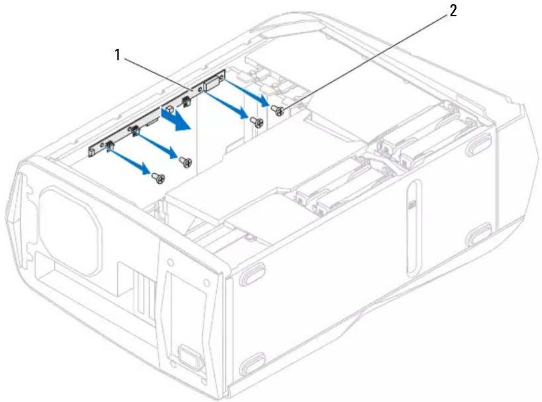
1 top lighting-board 2 screws (4)
Replacing the Top Lighting-Board
1 Align the screw holes on the top lighting-board with the screw holes on the chassis.
2 Replace the screws that secure the top lighting-board to the chassis.
3 Connect the cables to the connectors on the top lighting-board.
Postrequisites
1 Replace the media-card reader, if installed. See "Replacing the Media-Card Reader" on page 43.
2 Replace the optical drive(s). See "Replacing the Optical Drive(s)" on page 38.
3 Replace the left side-panel. See "Replacing the Left Side-Panel" on page 27.
4 Follow the steps in "After Working Inside Your Computer" on page 15.
Right-Side Top Panel

WARNING: Before working inside your computer, read the safety information that shipped with your computer and follow the steps in "Before You Begin" on page 13. For additional safety best practices information, see the Regulatory Compliance Homepage at dell.com/regulatory_compliance.
Prerequisites
1 Remove the left side-panel. See "Removing the Left Side-Panel" on page 25.
2 Open the PCI shroud. See "Opening the PCI Shroud" on page 45.
3 Remove the drive-bay shroud. See "Removing the Drive-Bay Shroud" on page 47.
Removing the Right-Side Top Panel
1 Locate the screw that secures the right-side top panel to the chassis.

natural_image
Architectural floor plan of a computer room showing CPU socket and drive bays (no text or labels)2 Remove the screw that secures the right-side top panel.

natural_image
Technical line drawing of a computer case chassis with internal components and a blue arrow indicating direction (no text or symbols present)1 screw
3 Place the computer in an upright position.
4 Slide the right-side top panel towards the front of the computer and pull it away from the chassis.
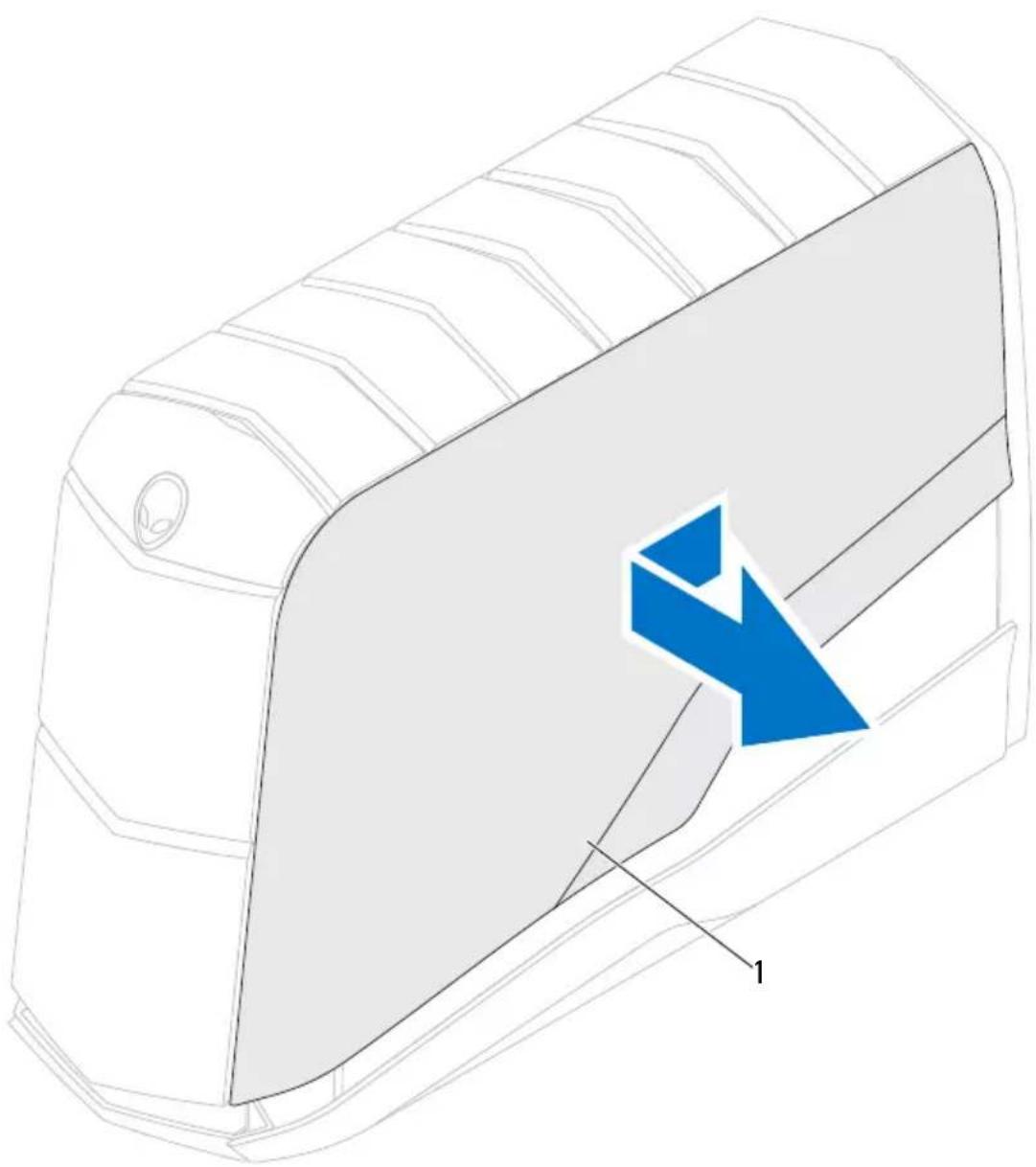
natural_image
Technical line drawing of a mechanical component with a blue arrow symbol indicating direction (no text or labels)1 right-side top panel
Replacing the Right-Side Top Panel
1 Align the tabs on the right-side top panel with the slots on the chassis and slide the panel into position.
2 Place the computer on its side with the right side facing up.
3 Replace the screw that secures the right-side top panel to the chassis.
Postrequisites
1 Replace the drive-bay shroud. See "Replacing the Drive-Bay Shroud" on page 48.
2 Close the PCI shroud. See "Closing the PCI Shroud" on page 46.
3 Replace the left side-panel. See "Replacing the Left Side-Panel" on page 27.
4 Follow the steps in "After Working Inside Your Computer" on page 15.
Right-Side Middle Panel

WARNING: Before working inside your computer, read the safety information that shipped with your computer and follow the steps in "Before You Begin" on page 13. For additional safety best practices information, see the Regulatory Compliance Homepage at dell.com/regulatory_compliance.
Prerequisites
1 Remove the left side-panel. See "Removing the Left Side-Panel" on page 25.
2 Open the PCI shroud. See "Opening the PCI Shroud" on page 45.
3 Remove the drive-bay shroud. See "Follow the steps in "After Working Inside Your Computer" on page 15." on page 46.
4 Remove the right-side top panel. See "Removing the Right-Side Middle Panel" on page 113.
5 Remove the right lighting-board. See "Removing the Right Lighting-Board" on page 117.
Removing the Right-Side Middle Panel
1 Remove the screws that secure the right-side middle panel to the chassis.
2 Lift the right-side middle panel up and away from the chassis.

1 screws (2) 2 right-side middle panel
Replacing the Right-Side Middle Panel
1 Align the right-side middle panel on top of the right-side bottom panel.
2 Replace the screws that secure the right-side middle panel to the chassis.
Postrequisites
1 Replace the right lighting-board. See "Replacing the Right Lighting-Board" on page 118.
2 Replace the right-side top panel. See "Replacing the Right-Side Top Panel" on page 110.
3 Replace the drive-bay shroud. See "Replacing the Drive-Bay Shroud" on page 48.
4 Close the PCI shroud. See "Closing the PCI Shroud" on page 46.
5 Replace the left side-panel. See "Replacing the Left Side-Panel" on page 27.
6 Follow the steps in "After Working Inside Your Computer" on page 15.
Right Lighting-Board

WARNING: Before working inside your computer, read the safety information that shipped with your computer and follow the steps in "Before You Begin" on page 13. For additional safety best practices information, see the Regulatory Compliance Homepage at dell.com/regulatory_compliance.
Prerequisites
1 Remove the left side-panel. See "Removing the Left Side-Panel" on page 25.
2 Open the PCI shroud. See "Opening the PCI Shroud" on page 45.
3 Remove the drive-bay shroud. See "Removing the Drive-Bay Shroud" on page 47.
4 Remove the right-side top panel. See "Removing the Right Lighting-Board" on page 117.
Removing the Right Lighting-Board
1 Disconnect the right lighting-board cable from the SIDE_R connector on the master I/O board.
2 Note the right lighting-board cable routing and remove it from the slot on the computer.
3 Remove the screws that secure the right lighting-board to the right-side middle panel.
4 Lift the right lighting-board along with its cable away from the right-side middle panel.

1 right lighting-board cable 2 right lighting-board
3 screws (3)
Replacing the Right Lighting-Board
1 Route the right lighting-board cable through the slot on the computer.
2 Align the screw holes on the right lighting-board with the screw holes on the right-side middle panel.
3 Replace the screws that secure the right lighting-board to the right-side middle panel.
4 Connect the right lighting-board cable to the connector on the master I/O board.
Postrequisites
1 Replace the right-side top panel. See "Replacing the Right-Side Top Panel" on page 110.
2 Replace the drive-bay shroud. See "Replacing the Drive-Bay Shroud" on page 48.
3 Close the PCI shroud. See "Closing the PCI Shroud" on page 46.
4 Replace the left side-panel. See "Replacing the Left Side-Panel" on page 27.
5 Follow the steps in "After Working Inside Your Computer" on page 15.
Right-Side Bottom Panel

WARNING: Before working inside your computer, read the safety information that shipped with your computer and follow the steps in "Before You Begin" on page 13. For additional safety best practices information, see the Regulatory Compliance Homepage at dell.com/regulatory_compliance.
Prerequisites
1 Remove the left side-panel. See "Removing the Left Side-Panel" on page 25.
2 Open the PCI shroud. See "Opening the PCI Shroud" on page 45.
3 Remove the drive-bay shroud. See "Removing the Drive-Bay Shroud" on page 47.
4 Remove the hard-drive fan assembly. See "Follow the steps in "After Working Inside Your Computer" on page 15." on page 69.
5 Remove the power-supply unit. See "Removing the Power-Supply Unit" on page 83.
6 Remove the right-side top panel. See "Removing the Right-Side Bottom Panel" on page 121.
7 Remove the right lighting-board. See "Removing the Right Lighting-Board" on page 117.
8 Remove the right-side middle panel. See "Removing the Right-Side Middle Panel" on page 113.
Removing the Right-Side Bottom Panel
1 Remove the screws that secure the right-side bottom panel to the chassis.

natural_image
Technical line drawing of a computer chassis with two blue arrows pointing to internal components (no text or symbols)1 screws (2)
2 Slide and remove the right-side bottom panel from the chassis.

natural_image
Technical line drawing of a mechanical component with a blue directional arrow indicating flow or movement (no text or symbols present)1 right-side bottom panel
Replacing the Right-Side Bottom Panel
1 Align the tabs on the right-side bottom panel with the slots on the chassis and slide the panel into position.
2 Replace the screws that secure the right-side bottom panel to the chassis.
Postrequisites
1 Replace the right-side middle panel. See "Replacing the Right-Side Middle Panel" on page 114.
2 Replace the right lighting-board. See "Replacing the Right Lighting-Board" on page 118.
3 Replace the right-side top panel. See "Replacing the Right-Side Top Panel" on page 110.
4 Replace the power-supply unit. See "Replacing the Power-Supply Unit" on page 86.
5 Replace the hard-drive fan assembly. See "Replacing the Hard-Drive Fan Assembly" on page 34.
6 Replace the drive-bay shroud. See "Replacing the Drive-Bay Shroud" on page 48.
7 Close the PCI shroud. See "Closing the PCI Shroud" on page 46.
8 Replace the left side-panel. See "Replacing the Left Side-Panel" on page 27.
9 Follow the steps in "After Working Inside Your Computer" on page 15.
Top Vent

WARNING: Before working inside your computer, read the safety information that shipped with your computer and follow the steps in "Before You Begin" on page 13. For additional safety best practices information, see the Regulatory Compliance Homepage at dell.com/regulatory_compliance.
Prerequisites
1 Remove the left side-panel. See "Removing the Left Side-Panel" on page 25.
2 Remove the memory fan. See "Removing the Memory Fan" on page 67.
3 Open the PCI shroud. See "Opening the PCI Shroud" on page 45.
4 Remove the drive-bay shroud. See "Removing the Drive-Bay Shroud" on page 47.
5 Remove the top lighting-board. See "Removing the Top Lighting-Board" on page 103.
6 Remove the system board. See "Removing the System-Board Assembly" on page 95.
7 Remove the right-side top panel. See "Removing the Right-Side Top Panel" on page 107.
Removing the Top Vent
1 Remove the screws that secure the top vent to the chassis.

1 screws (10) 2 top vent
2 Place the chassis in an upright position.
3 Remove the screws that secure the top I/O panel cover to the chassis.
4 Lift the top I/O panel cover away from the chassis.
5 Remove the screws that secure the top vent to the chassis.
6 Lift the top vent away from the chassis.

1 top-vent screws (3) 2 top I/O panel cover
3 top-panel screws (2) 4 top vent
Replacing the Top Vent
1 Align the screw holes on the top vent with the screw holes on the chassis.
2 Replace the screws that secure the top vent to the chassis.
3 Align the top panel with the slots in the chassis and replace the screws that secure the top panel to the chassis.
4 Place the computer on its side with the left side facing up.
5 Replace the screws that secure the top vent to the top of the chassis.
Postrequisites
1 Replace the right-side top panel. See "Replacing the Right-Side Top Panel" on page 110.
2 Replace the system board. See "Replacing the System-Board Assembly" on page 96.
3 Replace the top lighting-board. See "Replacing the Top Lighting-Board" on page 104.
4 Replace the drive-bay shroud. See "Replacing the Drive-Bay Shroud" on page 48.
5 Close the PCI shroud. See "Closing the PCI Shroud" on page 46.
6 Replace the memory fan. See "Replacing the Memory Fan" on page 68.
7 Replace the left side-panel. See "Replacing the Left Side-Panel" on page 27.
8 Follow the steps in "After Working Inside Your Computer" on page 15.
Front Bezel

WARNING: Before working inside your computer, read the safety information that shipped with your computer and follow the steps in "Before You Begin" on page 13. For additional safety best practices information, see the Regulatory Compliance Homepage at dell.com/regulatory_compliance.
Prerequisites
1 Remove the left side-panel. See "Removing the Left Side-Panel" on page 25.
2 Open the PCI shroud. See "Opening the PCI Shroud" on page 45.
3 Remove the drive-bay shroud. See "Removing the Drive-Bay Shroud" on page 47.
4 Remove the right-side top panel. See "Removing the Right-Side Top Panel" on page 107.
5 Remove the right lighting-board. See "Removing the Right Lighting-Board" on page 117.
6 Remove the right-side middle panel. See "Removing the Right-Side Middle Panel" on page 113.
7 Remove the right-side bottom panel. See "Removing the Right-Side Bottom Panel" on page 121.
Removing the Front Bezel
1 Remove the screws that secure the front bezel to the chassis.
2 Note the routing of the front-bezel cables and disconnect the front bezel cables from the connectors on the master I/O board.

1 screws (7)
3 Place the computer in an upright position.
4 Remove the screws that secure the front bezel to the chassis.
5 Pull the front bezel away from the chassis.
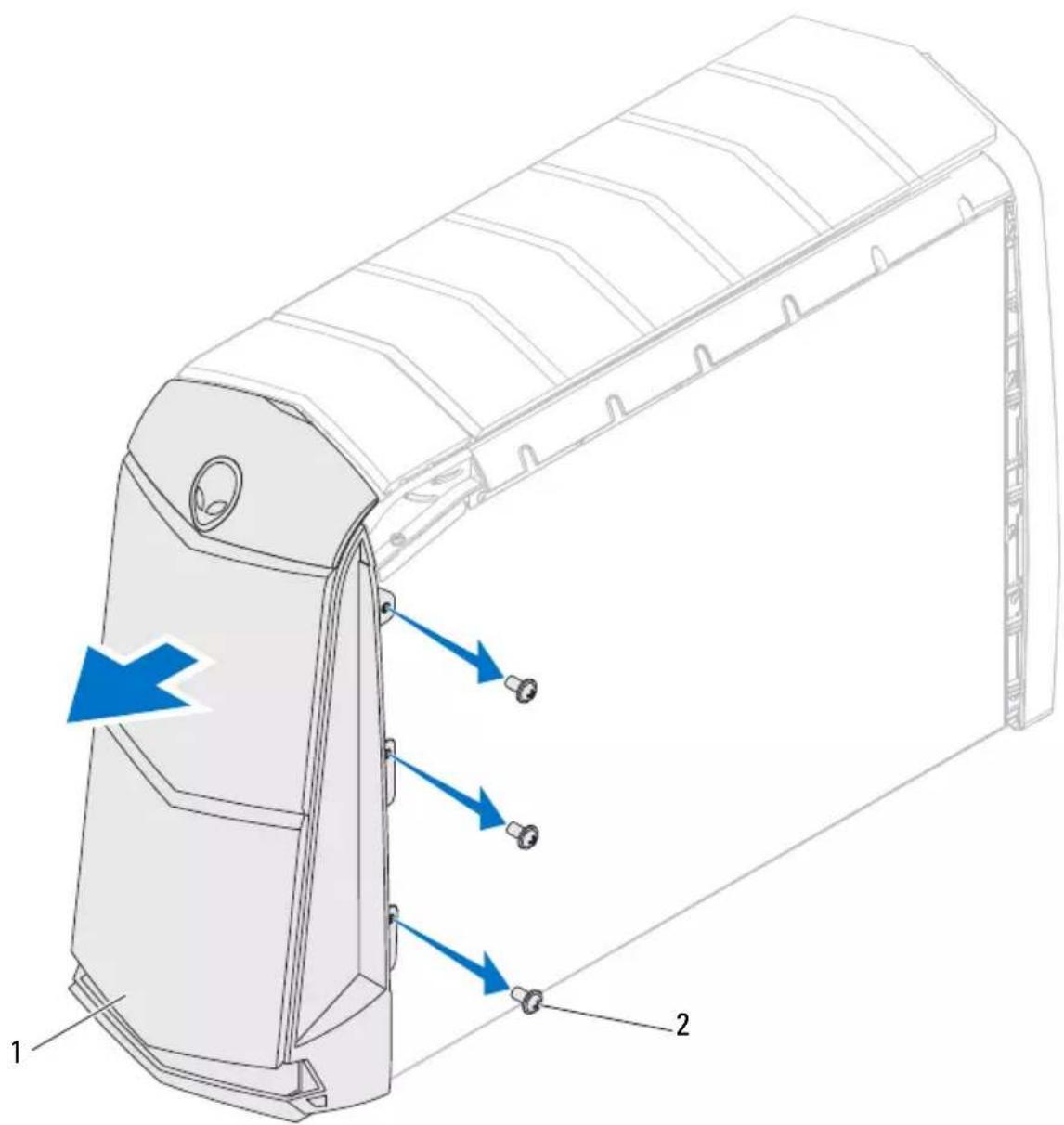
1 front bezel 2 screws (3)
Replacing the Front Bezel
1 Align the front bezel with the front of the chassis.
2 Replace the screws on the right side that secure the front bezel to the chassis.
3 Place the computer on its side with the left side facing up.
4 Route and connect the front-bezel cables to the connectors on the master I/O board.
5 Replace the screws that secure the front bezel to the chassis.
Postrequisites
1 Replace the right-side bottom panel. See "Replacing the Right-Side Bottom Panel" on page 123.
2 Replace the right-side middle panel. See "Replacing the Right-Side Middle Panel" on page 114.
3 Replace the right lighting-board. See "Replacing the Right Lighting-Board" on page 118.
4 Replace the right-side top panel. See "Replacing the Right-Side Top Panel" on page 110.
5 Replace the drive-bay shroud. See "Replacing the Drive-Bay Shroud" on page 48.
6 Close the PCI shroud. See "Closing the PCI Shroud" on page 46.
7 Replace the left side-panel. See "Replacing the Left Side-Panel" on page 27.
8 Follow the steps in "After Working Inside Your Computer" on page 15.
Back Bezel

WARNING: Before working inside your computer, read the safety information that shipped with your computer and follow the steps in "Before You Begin" on page 13. For additional safety best practices information, see the Regulatory Compliance Homepage at dell.com/regulatory_compliance.
Prerequisites
1 Remove the left side-panel. See "Removing the Left Side-Panel" on page 25.
2 Remove the power-supply unit. See "Removing the Power-Supply Unit" on page 83.
3 Remove the processor liquid-cooling assembly. See "Removing the Processor Liquid-Cooling Assembly" on page 71.
Removing the Back Bezel
1 Remove the screws that secure the security-lock panel to the chassis.
2 Pull the security-lock panel away from the chassis.

1 screws (2) 2 security-lock panel
3 Remove the screws that secure the back bezel to the chassis.
4 Release the tabs that secure the back bezel to the chassis.
5 Pull the back bezel away from the chassis.
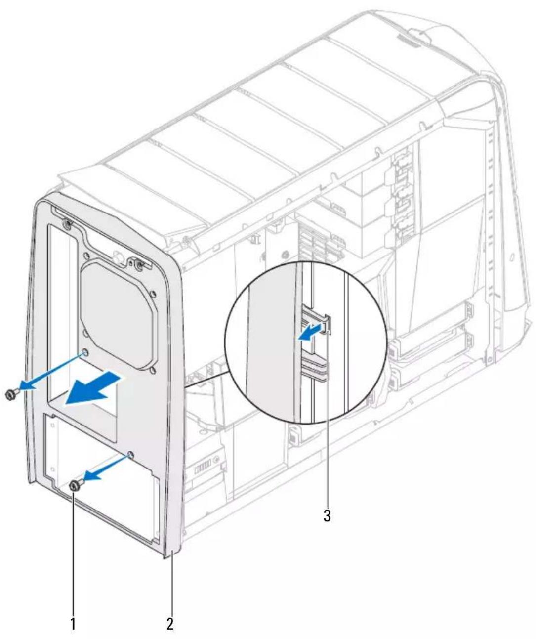
1 screws (2) 2 back bezel
3 tabs
Replacing the Back Bezel
1 Align the tabs on the back bezel with the slots on the chassis.
2 Push the back bezel into place.
3 Replace the screws that secure the back bezel to the chassis.
4 Replace the screws that secure the security-lock panel to the chassis.
Postrequisites
1 Replace the processor liquid-cooling assembly. See "Replacing the Processor Liquid-Cooling Assembly" on page 72.
2 Replace the power-supply unit. See "Replacing the Power-Supply Unit" on page 86.
3 Replace the left side-panel. See "Replacing the Left Side-Panel" on page 27.
4 Follow the steps in "After Working Inside Your Computer" on page 15.
WiFi/Bluetooth Assembly

WARNING: Before working inside your computer, read the safety information that shipped with your computer and follow the steps in "Before You Begin" on page 13. For additional safety best practices information, see the Regulatory Compliance Homepage at dell.com/regulatory_compliance.
Prerequisites
1 Remove the left side-panel. See "Removing the Left Side-Panel" on page 25.
2 Open the PCI shroud. See "Opening the PCI Shroud" on page 45.
3 Remove the drive-bay shroud. See "Removing the Drive-Bay Shroud" on page 47.
Removing the WiFi/Bluetooth Card
1 Disconnect the WiFi/Bluetooth assembly cable from the connector on the master I/O board.
2 Loosen the thumbscrew that secures the WiFi/Bluetooth assembly to the chassis.
3 Slide and pull the WiFi/Bluetooth assembly away from the chassis.

1 WiFi/Bluetooth assembly 2 thumbscrew
Replacing the WiFi/Bluetooth Card
1 Align the tab on the WiFi/Bluetooth assembly with the slot on the chassis and slide it into position.
2 Tighten the thumbscrew that secures the WiFi/Bluetooth assembly to the chassis.
3 Connect the WiFi/Bluetooth assembly cable to the connector on the master I/O board.
Postrequisites
1 Replace the drive-bay shroud. See "Replacing the Drive-Bay Shroud" on page 48.
2 Close the PCI shroud. See "Closing the PCI Shroud" on page 46.
3 Replace the left side-panel. See "Replacing the Left Side-Panel" on page 27.
4 Follow the steps in "After Working Inside Your Computer" on page 15.
Top I/O Panel

WARNING: Before working inside your computer, read the safety information that shipped with your computer and follow the steps in "Before You Begin" on page 13. For additional safety best practices information, see the Regulatory Compliance Homepage at dell.com/regulatory_compliance.
Prerequisites
1 Remove the left side-panel. See "Removing the Left Side-Panel" on page 25.
2 Open the PCI shroud. See "Opening the PCI Shroud" on page 45.
3 Remove the drive-bay shroud. See "Removing the Drive-Bay Shroud" on page 47.
4 Remove the PCI-Express xl card. See "Removing the PCI-Express xl Card" on page 49.
5 Remove the graphics card. See "Removing the Graphics Card" on page 57.
6 Remove the PCI-fan. See "Removing the PCI-Fan" on page 53.
7 Remove the right-side top panel. See "Removing the Right-Side Top Panel" on page 107.
8 Remove the right lighting-board. See "Removing the Right Lighting-Board" on page 117.
9 Remove the right-side middle panel. See "Removing the Right-Side Middle Panel" on page 113.
10 Remove the right-side bottom panel. See "Removing the Right-Side Bottom Panel" on page 121.
11 Remove the front bezel. See "Removing the Front Bezel" on page 129.
Removing the Top I/O Panel
1 Push the tab on the panel insert to release the panel insert from the slot on the chassis.
2 Pull the panel insert away from the chassis.
3 Remove the screws that secure the top I/O panel to the chassis.
4 Disconnect the top I/O panel cables from the connectors on the system board and master I/O board.
5 Slide and remove the top I/O panel out of the chassis.

1 panel insert 2 tab
3 top I/O panel 4 screws (4)
5 top panel
Replacing the Top I/O Panel
1 Slide the tabs on the top I/O panel into the slots on the chassis.
2 Connect the top I/O panel cables to the connectors on the system board and master I/O board.
3 Replace the screws that secure the top I/O panel to the chassis.
4 Align the tabs on the panel insert with the slots on the computer chassis.
Postrequisites
1 Replace the front bezel. See "Replacing the Front Bezel" on page 131.
2 Replace the right-side bottom panel. See "Replacing the Right-Side Bottom Panel" on page 123.
3 Replace the right-side middle panel. See "Replacing the Right-Side Middle Panel" on page 114.
4 Replace the right lighting-board. See "Replacing the Right Lighting-Board" on page 118.
5 Replace the right-side top panel. See "Replacing the Right-Side Top Panel" on page 110.
6 Replace the PCI-fan. See "Replacing the PCI-Fan" on page 54.
7 Replace the PCI-Express xl card. See "Replacing the PCI-Express xl Card" on page 50.
8 Replace the drive-bay shroud. See "Replacing the Drive-Bay Shroud" on page 48.
9 Close the PCI shroud. See "Closing the PCI Shroud" on page 46.
10 Replace the left side-panel. See "Replacing the Left Side-Panel" on page 27.
11 Follow the steps in "After Working Inside Your Computer" on page 15.
System Setup
Overview
Use the system setup to:
- get information about the hardware installed in your computer, such as the amount of RAM, the size of the hard drive, and so on
- change the system configuration information
- set or change a user-selectable option, such as the user password, type of hard drive installed, enabling or disabling base devices, and so on

NOTE: Before you change system setup, it is recommended that you note the system-setup screen information for future reference.
Entering System Setup
1 Turn on (or restart) your computer.
2 During POST, when the DELL logo is displayed, watch for the F2 prompt to appear and then press

NOTE: The F2 prompt indicates that the keyboard has initialized. This prompt can appear very quickly, so you must watch for it, and then press
System Setup Screens
The system setup screen displays current or changeable configuration information for your computer. Information on the screen is divided into three areas: the setup item, active help screen, and key functions.
| Setup Item — This field appears on the left side of the system setup window. The field is a scrollable list containing features that define the configuration of your computer, including installed hardware, power conservation, and security features. Scroll up and down the list with the up- and down-arrow keys. As an option is highlighted, the Help Screen displays more information about that option and available settings. | Help Screen — This field appears on the right side of the system setup window and contains information about each option listed in the Setup Item. In this field you can view information about your computer and make changes to your current settings. Press the up-arrow and down-arrow keys to highlight an option. Press <Enter> to make that selection active and return to the Setup Item. NOTE: Not all settings listed in the Setup Item are changeable. |
| Key Functions — This field appears below the Help Screen and lists keys and their functions within the active system setup field. | |
System Setup Options

NOTE: Depending on your computer and installed devices, the items listed in this section may appear, or may not appear exactly as listed.
Main
BIOS Information
Product Information
Build Date Displays the BIOS release date.
Product Name Displays the product name.
BIOS Version Displays the BIOS version number.
Set Service Tag Allows you to enter the service tag of your computer.
Asset Tag Displays the asset tag of the computer.
Memory Information
Total Memory Displays the total memory of the computer.
Memory Available Displays the amount of memory available on the computer.
Memory Technology Displays the type of memory technology used.
Memory Speed Displays the memory speed.
CPU Information
Processor ID Displays the processor identification code.
CPU Speed Displays the processor speed.
Cache L2 Displays the processor L2 cache size.
Cache L3 Displays the processor L3 cache size.
Advanced — Standard CMOS Features
| System Date(mm:dd:yy) | Displays current date. |
| System Time(hh:mm:ss) | Displays the current time. |
| Device Information | |
| SATA Port1 | Displays the SATA 1 drive integrated in the computer. |
| SATA Port2 | Displays the SATA 2 drive integrated in the computer. |
| SATA Port3 | Displays the SATA 3 drive integrated in the computer. |
| SATA Port4 | Displays the SATA 4 drive integrated in the computer. |
| SATA Port5 | Displays the SATA 5 drive integrated in the computer. |
| SATA Port6 | Displays the SATA 6 drive integrated in the computer. |
| Wait for 'F1' If Errors If enabled, the system will HALT during boot to display system errors. | |
Advanced — Advanced BIOS Features
Bootup Num-Lock Select power-on state for num-lock.
OptionROM Display Screen Allows you to display or hide the RAID Option ROM screen during POST.
| Advanced — CPU Configuration | |
| Hyper-threading Technology | If disabled only one thread per enabled core is active. |
| XD Bit Capability Enable XD Bit Capability to allow the processor to distinguish between the bits of code that can be executed and the ones that cannot be executed. | |
| Intel(R) Speedstep tech If enabled, the processor clock speed and core voltage are adjusted dynamically based on the processor load. | |
| Active Processor Cores Allows you to enable the number of cores in each processor package. Options 1-5. | |
Advanced — Integrated Devices
| USB Controller Allows you to enable or disable the integrated USB controller. |
| HD Audio Allows you to enable or disable the integrated audio controller. |
| Onboard LAN Controller Allows you to enable or disable the onboard LAN controller. |
| Launch PXE OpROM Allows you to enable or disable the boot option for legacy network devices. |
| PCH SATA Configuration |
| SATA Mode Allows you to configure the integrated hard drive controller to AHCI or RAID. |
Advanced — Power Management Setup
| Suspend Mode Sets the energy-saving mode of the ACPI function. | |
| AC Recovery Sets what action the computer takes when power is restored. | |
| Auto Power On | Allows the computer to start up at a certain time. |
| Auto Power On Date | Allows you to set RTC Wake Up Date. |
Auto Power On Hour Allows you to set RTC Wake Up Hour.
Auto Power On Minute Allows you to set RTC Wake Up Minute.
Auto Power On Second Allows you to set RTC Wake Up Second
Advanced — Frequency/Voltage Control
| Current CPU Frequency Displays the current processor speed. | |
| Current DRAM Frequency Displays the current memory speed. | |
| Spread Spectrum Enabling this option could reduce the EMI. | |
| Internal PLL Overvoltage Enable Internal PLL Overvoltage for K-SKU CPUs to get better over clocking capability. | |
| DMI Base Clock Base clock for DMI | |
| CPU Gear Ratio Base clock for CPU and DRAM only | |
| Adjust CPU Ratio Allows you to adjust the CPU ratio. | |
| DRAM Frequency Allows you to adjust the DRAM frequency. | |
| Extreme Memory Profile (X.M.P) | Allows you to change the extreme memory profile value. |
| DRAM Timing Mode Allows you to change the memory timing mode. | |
| Advance DRAM Configuration Allows you to change the Advance DRAM Configuration. | |
| CPU Power Management Configuration | Allows you to access the CPU Power Management Configuration submenu. |
| Overvoltage Configuration Allows you to access the Overvoltage Configuration submenu. | |
Advance DRAM Configuration Submenu
| Command Rate Displays the Command Rate (editable in Manual Mode). | |
| tCL | Displays the Column Address Strobe Latency (editable in Manual Mode). |
| tRCD | Displays timing of RAS to CAS delay (editable in Manual Mode). |
| tRP | Displays timing of RAS Precharge (editable in Manual Mode). |
| tRAS | Displays timing of Row Address Strobe (editable in Manual Mode). |
| tRFC | Displays timing of Refresh to Archive/Refresh cycle time (editable in Manual Mode). |
| tWR | Displays timing of Write Recover (editable in Manual Mode). |
| tWTR | Displays Write to Read Delay (editable in Manual Mode). |
| tRRD | Displays RAS to RAS delay (editable in Manual Mode). |
| tRTP | Displays Read to Precharge Command Delay (editable in Manual Mode). |
| tFAW | Displays the Four Activate Window (editable in Manual Mode). |
| tWCL | Displays the Write CAS Latency (editable in Manual Mode). |
| tCKE | Displays the Minimum CKE High and Low Pulse Width (editable in Manual Mode). |
| tRTL | Displays the Round Trip Latency (editable in Manual Mode). |
| tXP | Displays the XP value (editable in Manual Mode). |
CPU Power Management Configuration
Intel Turbo Boost If enabled, allows processor to run at faster frequencies than marked.
Long duration power limit Allows you to change the long duration power limit.
| Long duration maintained Allows you to change the long duration time limit. | ||
| Short duration power limit Allows you to change the short duration power limit. | ||
| 1-Core Ratio Limit Allows you to change the ratio limit of the processor's first core. | ||
| 2-Core Ratio Limit Allows you to change the ratio limit of the processor's second core. | ||
| 3-Core Ratio Limit Allows you to change the ratio limit of the processor's third core. | ||
| 4-Core Ratio Limit Allows you to change the ratio limit of the processor's fourth core. | ||
| 5-Core Ratio Limit Allows you to change the ratio limit of the processor's fifth core. | ||
| 6-Core Ratio Limit Allows you to change the ratio limit of the processor's sixth core. | ||
| VID for Max Turbo Ratio Allows you to change the VID override for max turbo ration value. |
Overvoltage Configuration Submenu
| Dynamic CPU VCore Offset Allows you to change the Processor Core Voltage Offset value. | |
| DDR3 Memory Voltage Adjusts the DDR3 Memory Voltage. | |
| DDR3 Memory Voltage Adjusts the DDR3 Memory Voltage. | |
| DMI and Uncore Voltage (2AH OUT1) | 2AH OUT1. |
| CPU PLL 1.8V 2AH OUT2. | |
| Load Level 1 OC Setting Allows you to select OC Level Profile 1 | |
| Load Level 2 OC Setting Allows you to select OC Level Profile 2 | |
Security
Supervisor Password: Allows you to change the supervisor password.
User Password: Allows you to change the user password.
You cannot use the user password to enter the BIOS setup, during POST.
Set Supervisor Password Allows you to set a supervisor password.
Boot
| Set Boot Priority | |
| 1st Boot Device | Displays the first boot device. |
| 2nd Boot Device | Displays the second boot device. |
| 3rd Boot Device | Displays the third boot device. |
| 4th Boot Device | Displays the fourth boot device. |
| 5th Boot Device | Displays the fifth boot device. |
| 6th Boot Device | Displays the sixth boot device. |
| 7th Boot Device | Displays the seventh boot device. |
| Hard Disk Drive BBS Priorities | Sets the hard drive boot priority. The items displayed are dynamically updated according to the hard drives detected. |
| CD/DVD ROM Drive BBS Priorities | Sets the CD/DVD drive boot priority. |
Exit
| Provides options to Save Changes and Reset,Discard Changes and Reset,andRestore Defaults. |
Boot Sequence
This feature allows you to change the boot sequence for devices.
Boot Options
- Diskette Drive — The computer attempts to boot from the floppy disk drive. If no operating system is on the drive, the computer generates an error message.
-
Hard Drive — The computer attempts to boot from the primary hard drive. If no operating system is on the drive, the computer generates an error message.
-
CD/DVD/CD-RW Drive — The computer attempts to boot from the optical drive. If no disc is in the drive, or if the disc is not bootable, the computer generates an error message.
- USB Storage Device — Insert the memory device into a USB connector and restart the computer. When F12 Boot Options appears in the lower-right corner of the screen, press
. The BIOS detects the device and adds the USB flash option to the boot menu.

NOTE: To boot to a USB device, the device must be bootable. To ensure that your device is bootable, check the device documentation.
- Network — The computer attempts to boot from the network. If no operating system is found on the network, the computer generates an error message.
Changing Boot Sequence for the Current Boot
You can use this feature to change the current boot sequence, for example, to boot from the optical drive to run Dell Diagnostics from the Drivers and Utilities disc. The previous boot sequence is restored at the next boot.
1 If you are booting from a USB device, connect the USB device to a USB connector.
2 Turn on (or restart) your computer.
3 When F2 Setup, F12 Boot Options appears in the lower-right corner of the screen, press

NOTE: If you wait too long and the operating system logo appears, continue to wait until you see the Microsoft Windows desktop. Then shut down your computer and try again.
The Boot Device Menu appears, listing all available boot devices.
4 On the Boot Device Menu choose the device you want to boot from.
For example, if you are booting to a USB memory key, highlightUSB Storage Device and press
Changing Boot Sequence for Future Boots
1 Enter system setup. See "Entering System Setup" on page 145.
2 Use the arrow keys to highlight the Boot menu option and press

NOTE: Write down your current boot sequence in case you want to restore it.
3 Press the up- and down-arrow keys to move through the list of devices.
4 Press plus (+) or minus (−) to change the boot priority of the device.
Clearing Forgotten Passwords

WARNING: Before working inside your computer, read the safety information that shipped with your computer and follow the steps in "Before You Begin" on page 13. For additional safety best practices information, see the Regulatory Compliance Homepage at dell.com/regulatory_compliance.

WARNING: The computer must be disconnected from the electrical outlet to clear the CMOS setting.
1 Remove the left side-panel. See "Removing the Left Side-Panel" on page 25.
2 Locate the 3-pin password reset jumper (PASSWORD_CLEAR) on the system board. See "System-Board Components" on page 20.
3 Remove the 2-pin jumper plug from pins 2 and 3 and fix it on pins 1 and 2.
Password:

4 Wait for approximately five seconds to clear the password setting.
5 Remove the 2-pin jumper plug from pins 1 and 2 and replace it on pins 2 and 3.
6 Replace the left side-panel. See "Replacing the Left Side-Panel" on page 27.
7 Follow the steps in "After Working Inside Your Computer" on page 15.
Clearing CMOS Passwords

WARNING: Before working inside your computer, read the safety information that shipped with your computer and follow the steps in "Before You Begin" on page 13. For additional safety best practices information, see the Regulatory Compliance Homepage at dell.com/regulatory_compliance.

WARNING: The computer must be disconnected from the electrical outlet to clear the CMOS setting.
1 Remove the left side-panel. See "Left Side-Panel" on page 25.
2 Locate the 3-pin CMOS reset jumper (CMOS_CLEAR) on the system board. See "System-Board Components" on page 20.
3 Remove the 2-pin jumper plug from pins 2 and 3 and fix it on pins 1 and 2.
CMOS:

4 Wait for approximately five seconds to clear the CMOS setting.
5 Remove the 2-pin jumper plug from pins 1 and 2 and replace it on pins 2 and 3.
6 Replace the left side-panel. See "Replacing the Left Side-Panel" on page 27.
7 Follow the steps in "After Working Inside Your Computer" on page 15.
Flashing the BIOS
The BIOS may require flashing when an update is available or when replacing the system board. To flash the BIOS:
1 Turn on the computer.
2 Go to support.dell.com/support/downloads.
3 Locate the BIOS update file for your computer:

NOTE: The Service Tag for your computer is located on a label at the back of your computer.
If you have your computer's Service Tag:
a Click Enter a Tag
b Enter your computer's Service Tag in the Enter a service tag: field, click Go, and proceed to step 4.
If you do not have your computer's Service Tag:
a Click Select Model.
b Select the type of product in the Select Your Product Familylist.
c Select the product brand in the Select Your Product Line list.
d Select the product model number in the Select Your Product Model list.

NOTE: If you have selected a different model and want to start over again, click Start Over on the top right of the menu.
e Click Confirm.
4 A list of results appears on the screen. Click BIOS.
5 Click Download Now to download the latest BIOS file.
The File Download window appears.
6 Click Save to save the file on your desktop. The file downloads to your desktop.
7 Click Close if the Download Complete window appears.
The file icon appears on your desktop and is titled the same as the downloaded BIOS update file.
8 Double-click the file icon on the desktop and follow the instructions on the screen.
Specifications
To learn about the features and advanced options available on your desktop, see Specifications at support.dell.com/manuals
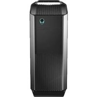
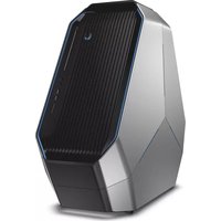
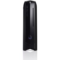
- Notes, Cautions, and Warnings
- Contents
- Hard Drive(s) 29
- Hard-Drive Fan Assembly 33
- Optical Drive(s) 37
- Media-Card Reader 41
- PCI Shroud.... 45
- Drive-Bay Shroud 47
- PCI-Express x1 Card 49
- PCI-Fan 53
- Graphics Card 57
- Memory Module(s).... 63
- Memory Fan.... 67
- Processor Liquid-Cooling Assembly .... 71
- Processor 75
- Power-Supply Unit.... 83
- Coin-Cell Battery 89
- Theater-Lighting Batteries (ALX Chassis Only) 93
- System-Board Assembly 95
- Master I/O Board 99
- Back Bezel.... 133
- WiFi/Bluetooth Assembly 137
- Top I/O Panel 141
- System Setup 145
- Clearing Forgotten Passwords. 154
- Clearing CMOS Passwords 156
- Before You Begin
- Turn Off Your Computer and Connected Devices
- Safety Instructions
- Recommended Tools
- After Working Inside Your Computer
- Technical Overview
- Front View of Your Computer
- Back View of Your Computer
- Inside View of Your Computer
- Master I/O Board Components
- Top Lighting-Board Components
- Left Side-Panel
- Removing the Left Side-Panel
- Replacing the Left Side-Panel
- Hard Drive(s)
- Prerequisites
- Removing the Hard Drive(s)
- Replacing the Hard Drive(s)
- Postrequisites
- Hard-Drive Fan Assembly
- Removing the Hard-Drive Fan Assembly
- Replacing the Hard-Drive Fan Assembly
- Optical Drive(s)
- Removing the Optical Drive(s)
- Replacing the Optical Drive(s)
- Media-Card Reader
- Removing the Media-Card Reader
- Replacing the Media-Card Reader
- PCI Shroud
- Opening the PCI Shroud
- Closing the PCI Shroud
- Drive-Bay Shroud
- Removing the Drive-Bay Shroud
- Replacing the Drive-Bay Shroud
- PCI-Express x1 Card
- Removing the PCI-Express x1 Card
- Replacing the PCI-Express x1 Card
- PCI-Fan
- Removing the PCI-Fan
- Replacing the PCI-Fan
- Graphics Card
- Removing the Graphics Card
- Replacing the Graphics Card
- Installing Dual Graphic Cards
- Connect the Display
- Memory Module(s)
- Removing Memory Module(s)
- Replacing Memory Module(s)
- Type Slots
- Memory Fan
- Removing the Memory Fan
- Replacing the Memory Fan
- Processor Liquid-Cooling Assembly
- Removing the Processor Liquid-Cooling Assembly
- Replacing the Processor Liquid-Cooling Assembly
- Processor
- Removing the Processor
- Replacing the Processor
- Power-Supply Unit
- Removing the Power-Supply Unit
- Replacing the Power-Supply Unit
- Coin-Cell Battery
- Removing the Coin-Cell Battery
- Replacing the Coin-Cell Battery
- Theater-Lighting Batteries (ALX Chassis Only)
- Removing the Theater-Lighting Batteries
- Replacing the Theater-Lighting Batteries
- System-Board Assembly
- Removing the System-Board Assembly
- Replacing the System-Board Assembly
- Entering the Service Tag in BIOS
- Master I/O Board
- Removing the Master I/O Board
- Replacing the Master I/O Board
- Top Lighting-Board
- Removing the Top Lighting-Board
- Replacing the Top Lighting-Board
- Right-Side Top Panel
- Removing the Right-Side Top Panel
- Replacing the Right-Side Top Panel
- Right-Side Middle Panel
- Removing the Right-Side Middle Panel
- Replacing the Right-Side Middle Panel
- Right Lighting-Board
- Removing the Right Lighting-Board
- Replacing the Right Lighting-Board
- Right-Side Bottom Panel
- Removing the Right-Side Bottom Panel
- Replacing the Right-Side Bottom Panel
- Top Vent
- Removing the Top Vent
- Replacing the Top Vent
- Front Bezel
- Removing the Front Bezel
- Replacing the Front Bezel
- Back Bezel
- Removing the Back Bezel
- Replacing the Back Bezel
- WiFi/Bluetooth Assembly
- Removing the WiFi/Bluetooth Card
- Replacing the WiFi/Bluetooth Card
- Top I/O Panel
- Removing the Top I/O Panel
- Replacing the Top I/O Panel
- System Setup
- Overview
- Entering System Setup
- System Setup Screens
- System Setup Options
- Main
- Advanced — Advanced BIOS Features
- CPU Power Management Configuration
- Security
- Boot Sequence
- Boot Options
- Changing Boot Sequence for the Current Boot
- Changing Boot Sequence for Future Boots
- Clearing Forgotten Passwords
- Password:
- Clearing CMOS Passwords
- CMOS:
- Flashing the BIOS
- Specifications
Brand : ALIENWARE
Model : Aurora AAR4
Category : Desktop computer