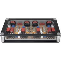
Thesis THX 2 II - Audio Electronics AUDISON - Free user manual and instructions
Find the device manual for free Thesis THX 2 II AUDISON in PDF.


| Product Type | 2-Channel Car Audio Amplifier |
| THX Certification | Yes |
| Power Output (RMS @ 4 ohms) | 2 x 200 W |
| Power Output (RMS @ 2 ohms) | 2 x 400 W |
| Bridged Power (RMS @ 4 ohms) | 1 x 800 W |
| Frequency Response | 10 Hz - 50 kHz (±1 dB) |
| Total Harmonic Distortion (THD) | ≤ 0.05% |
| Signal-to-Noise Ratio | ≥ 100 dB (A-weighted) |
| Damping Factor | > 200 @ 4 ohms, 100 Hz |
| Input Sensitivity | 0.2 V - 8 V |
| Input Impedance | 47 kΩ |
| Crossover Type | Variable Low-Pass / High-Pass / Full Range |
| Crossover Slope | 12 dB/octave (Butterworth) |
| Bass Boost | 0 - 12 dB @ 45 Hz |
| Phase Shift | 0° / 180° |
| Power Supply Voltage | 11 - 15 V DC |
| Dimensions (W x H x D) | 500 x 50 x 200 mm |
| Weight | 3.5 kg |
| Protection Circuits | Thermal, Short Circuit, Overvoltage, Under Voltage |
| Recommended Fuse | 60 A |
| Speaker Impedance | 2 - 8 Ω (stereo), 4 - 8 Ω (bridged) |
| Audio Inputs | 2 x RCA |
| Audio Outputs | 2 x Speaker terminals |
| Remote Turn-On | Yes |
Frequently Asked Questions - Thesis THX 2 II AUDISON
User questions about Thesis THX 2 II AUDISON
0 question about this device. Answer the ones you know or ask your own.
Ask a new question about this device
Download the instructions for your Audio Electronics in PDF format for free! Find your manual Thesis THX 2 II - AUDISON and take your electronic device back in hand. On this page are published all the documents necessary for the use of your device. Thesis THX 2 II by AUDISON.
USER MANUAL Thesis THX 2 II AUDISON
THESIS
Index
02
THESIS - The project 03
Assembling and Cable connection 04
Size 05
THX 2
THX 2 Mono-Wiring connections 07
THX 2 Bi-Wiring connections 08
THX 2 Installation recommended with default set filter 09
THX 2 Installation with door mounted tweeter 10
THX 2 Tweeter Level Ajustment 11
THX 2 LFS (Low Frequency Shaping): Adjusting Low Frequency Response to eliminate resonances 12
THX 2 How to disassemble the circuit board "Step 1" "Step 2" 13
THX 2 How to disassemble the circuit board "Step 3" "Step 4" 14
THX 2 Modifications on the single components 15
THX mh
THX mh Mono-Wiring connections 17
THX mh Bi-Wiring connections 18
THX mh Installation recommended with default set filter 19
THX mh Installation with door mounted midrange 20
THX mh Tweeter Level Adjustment 21
THX mh Midrange Hi-pass: Activation of the High-pass filter for the midrange" 22
THX mh How to disassemble the circuit board "Step 1" "Step 2" 23
THX mh How to disassemble the circuit board "Step 3" "Step 4" 24
THX mh Modifications on the single components 25
THX 3
THX 3 Mono-Wiring connections 27
THX 3 Bi-Wiring connections 28
THX 3 Tri-Wiring connections 29
THX 3 Installation recommended with default set filter 30
THX 3 Installation with door mounted midrange 31
THX 3 Installation with door mounted double woofer 32
THX 3 Installation with door mounted double woofer and midrange 33
THX 3 Tweeter Level Adjustment 34
THX 3 Midrange Level Adjustment 35
THX 3 LFS (Low Frequency Shaping): Adjusting Low Frequency Response to eliminate resonances 36
THX 3 How to disassemble the circuit board "Step 1" "Step 2" 37
THX 3 How to disassemble the circuit board "Step 3" "Step 4" 38
THX 3 Modifications on the single components 39
Technical Specifications 40
THESIS
The Project
In order to create a system capable of reproducing amazing, first-class Sound, each acoustical component must abide to the most elevated standards of quality and design.
The Thesis amplifiers offer their best performance when used with speakers designed with the same philosophy. Throughout the years Thesis has represented a name referenced to the perfection of electronic design and performance. Today, technological development has enabled us to push the envelope in terms of the prestigious Thesis tradition. Creating a supreme product in amplification, the Audison development team has achieved their ambition of reproducing an unparalleled Sound.
Appropriate tuning
Assembling a speaker system imposes choices in which parameters such as personal taste, the physical installation limits and the acoustic environment of the vehicle itself have to be considered. Thesis speakers ensure the highest performance with both multi-amplified active systems and with systems using “passive” crossovers.
Pairing TH speakers with the TH amplifiers intensifies the synergy of products belonging to the same magnificent project. Therefore, choosing an active multi-amplified system or the use of passive crossovers is merely a question of personal taste.
The available crossover networks are:
THX 2, for a full range two-way system with TH 1.5 violino and TH 6.5 sax;
THX 3, for a full range three-way system with TH 1.5 violino, TH 3.0 voce and TH 6.5 sax;
THX mh, for a mid to high frequency system with TH 3.0 voce and TH 1.5 violino as part of a "mixed" multi-way system.
Open design
Each filter is, in actual fact, an “open” design which can be customised in order to obtain the best acoustic response in any environment.
Extreme customization
A mother board, designed for maximum versatile adaptation, provides the ability for anyone to customize their own THX crossover.
Designed as a continued project in-progress, it is possible to change and set:
- the power connection mode for BiWiring or when used as a passive multi-amplified system;
- the output level of every single speaker;
- the cut-off frequency of every single output;
- the filter cut-off slope;
- the Q (quality factor) at the crossover frequency;
- the use of notch filters to adjust the system to the vehicles acoustics.
Audison Thesis Advisor
The THX crossover default configuration has been designed to achieve the highest sound quality levels. This Advanced Manual offers complete information to fully enjoy their potential.
Each user has at his/her disposal the best support to make the most of the Thesis line expandability and customization possibilities. Through the “Support” area of the Audison website the user can interact with the Audison Thesis Advisor to be guided by a professional inside the Audison R&D Division who will provide him/her with the opportunity to further enhance their crossover.
A mother board, designed for maximum versatile adaptation, provides the ability for the users to customize their own THX crossover.
THESIS
Assembling

Cable connection

THESIS
Size


THX 2 THX mh THX 3
| A B C D E | ||||
| 190 166 348 324 66,57"1/2 6"1/2 13"3/4 | ||||
| 258 234 438 414 66,510"3/16 9"1/4 17"1/4 | ||||
| Misure espresse in millimetri e pollici / Measures in mm and inches | ||||
THX 2
PATTERNS
TUNING KIT (supplied)
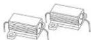
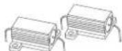
N° 2 1Ω, 10W Resistors
N° 2 2,2Ω, 10W Resistors
N° 2 3,3Ω, 10W Resistors
N° 2 4,7Ω, 10W Resistors
N° 2 5,6Ω, 10W Resistors
N° 2 1μF, 330V Polypropylene capacitors
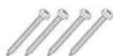
N° 4 4, 2 x 3 8 m m cross headed, self-tapping fixing screws


THX 2 Mono-Wiring connection


THX 2 Bi-Wiring connection

THX 2 Installation recommended with default set filter
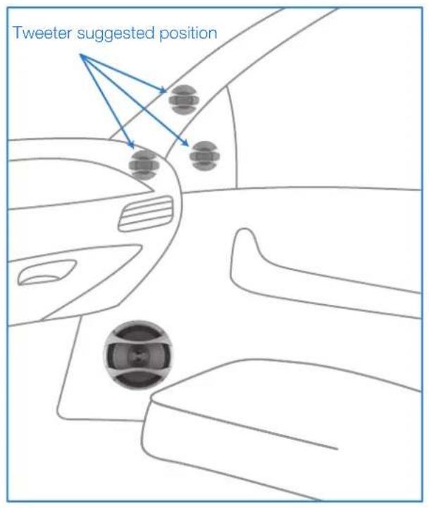

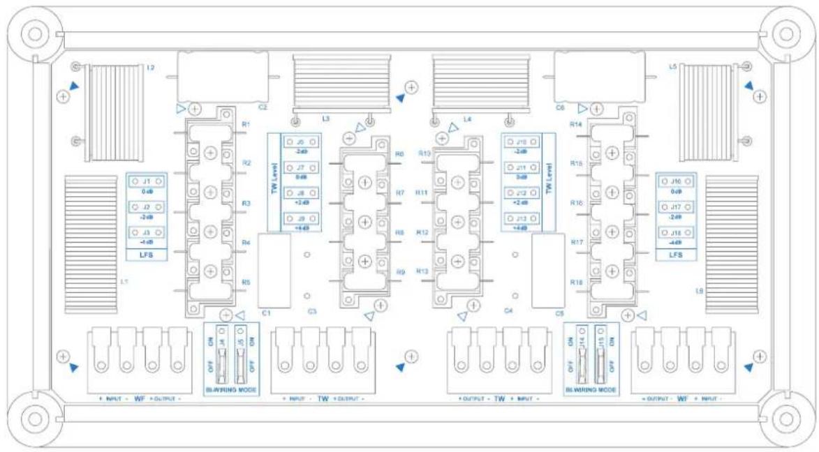
THX 2 Installation with door mounted tweeter

Right Channel
Left Channel
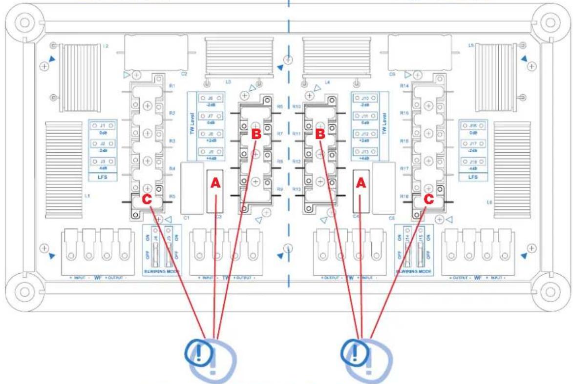
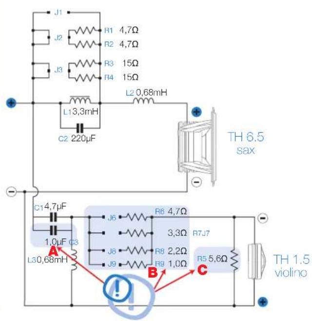
WORK ON THESE COMPONENTS! (see page 13÷15)
THX 2 Tweeter Level Adjustment

THX 2 LFS (Low Frequency Shaping)
Adjusting Low Frequency Response to eliminate resonances

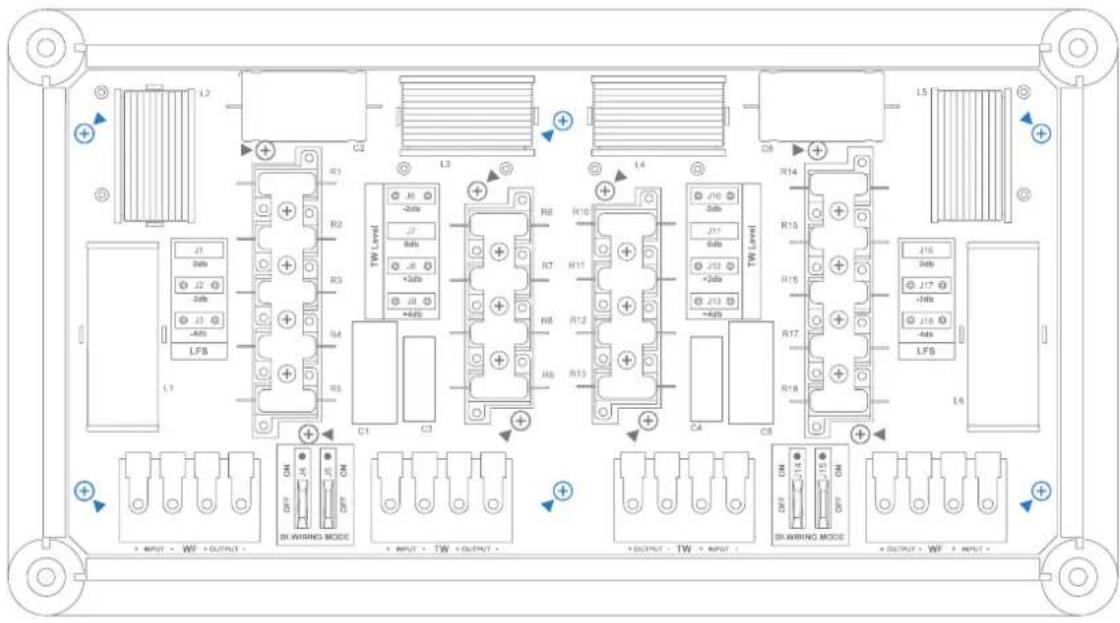
THX 2 How to disassemble the circuit board
Step 1: remove plexiglass cover (see page 4)
Step 2: remove the main screws (marked in blue)
Left Channel Right Channel

THESIS
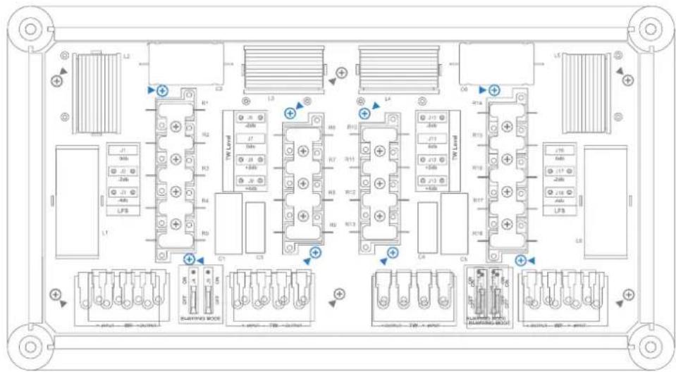
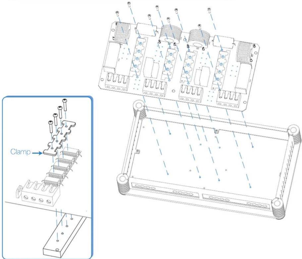
THX 2 How to disassemble the circuit board
Step 3: remove the screws that secure the resistor blocks (marked in blue)
Step 4: remove the screws that secure the resistors with the clamps
THX 2 Modifications on the single components
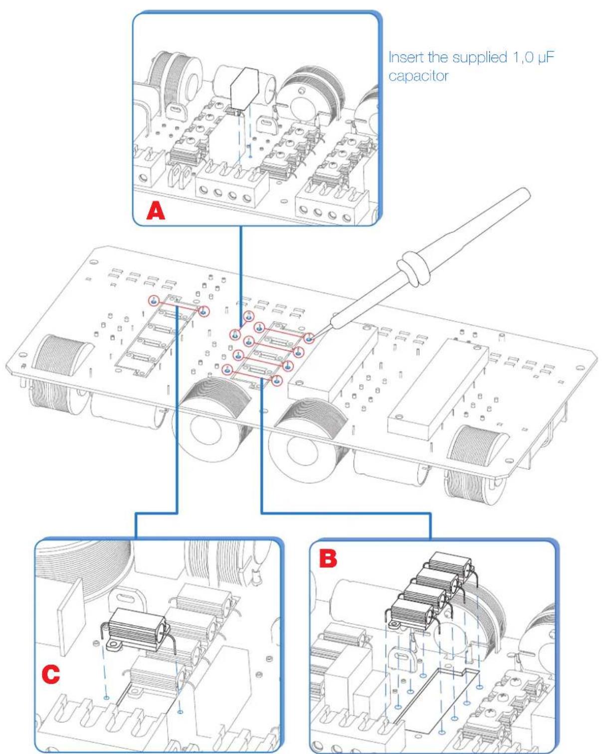
Replace the 6,8Ω resistor originally mounted with a 5,6Ω one supplied with the product
Replace the supplied resistors originally mounted following the diagram on page 10

TUNING KIT (supplied)
N° 2 1.5 mH, ∅ 42 mm inductances
N° 2 1μF, 330V Polypropylene capacitors
N° 4 4 , 2 x 3 8 m m cross headed, self-tapping fixing screws


THX mh Mono-Wiring connection


THX mh Bi-Wiring connection
Left Channel Right Channel

THESIS
THX mh Installation recommended with default set filter


THX mh Installation with door mounted midrange


Left Channel
Right Channel
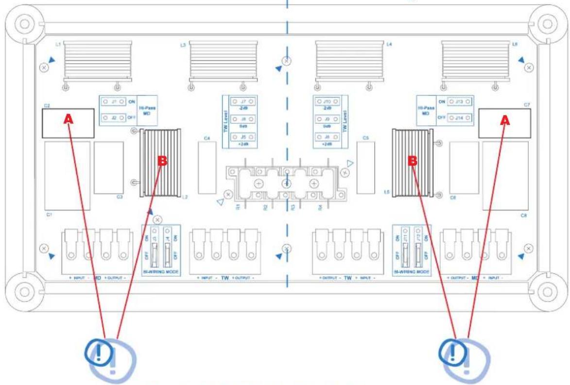
WORK ON THESE COMPONENTS! (see Page 23÷25)
THX mh Tweeter Level Adjustment

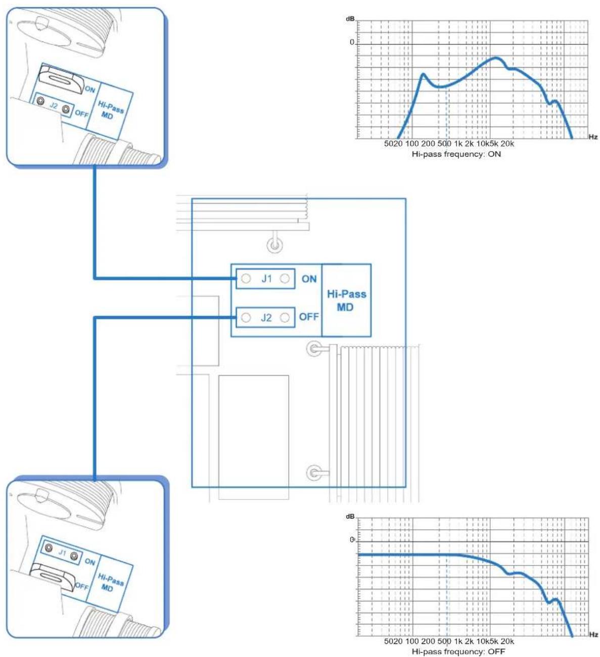
THX mh Midrange Hi-pass
Activation of the High-pass filter for the midrange
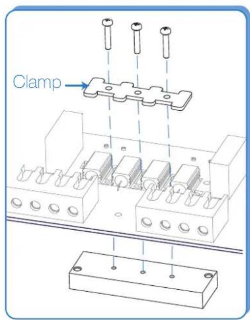
THX mh How to disassemble the circuit board
Step 1: remove plexiglass cover (see page 4)
Step 2: remove the main screws (marked in blue)
Left Channel Right Channel


THX mh How to disassemble the circuit board
Step 3: remove the screws that secure the resistor blocks (marked in blue)
Step 4: remove the screws that secure the resistors with the clamps
Left Channel Right Channel


THX mh Modifications on the single components
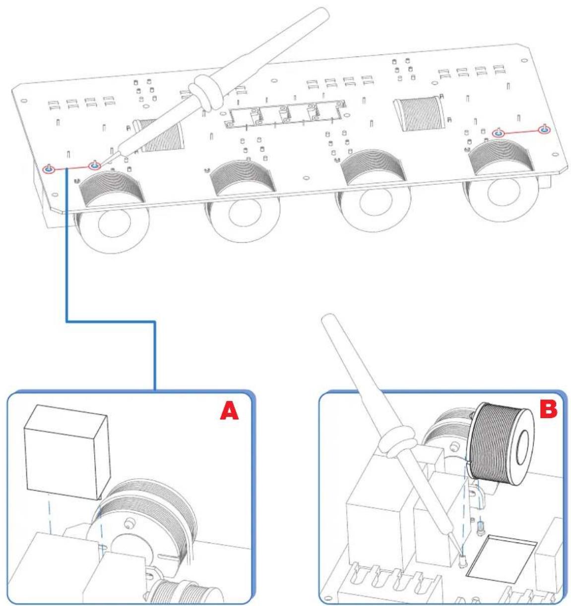
Insert the supplied 10 µ F capacitor
Insert the supplied 1,5 mH coil
THX 3
PATTERNS
TUNING KIT (supplied)
N° 2 1.5 mH, ∅ 42 mm inductances
N° 4 4 , 2 x 3 8 m m cross headed, self-tapping fixing screws


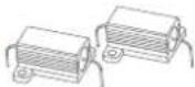
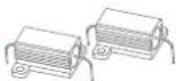


THX 3 Mono-Wiring connection
Left Channel Right Channel


THX 3 Bi-Wiring connection
Left Channel Right Channel
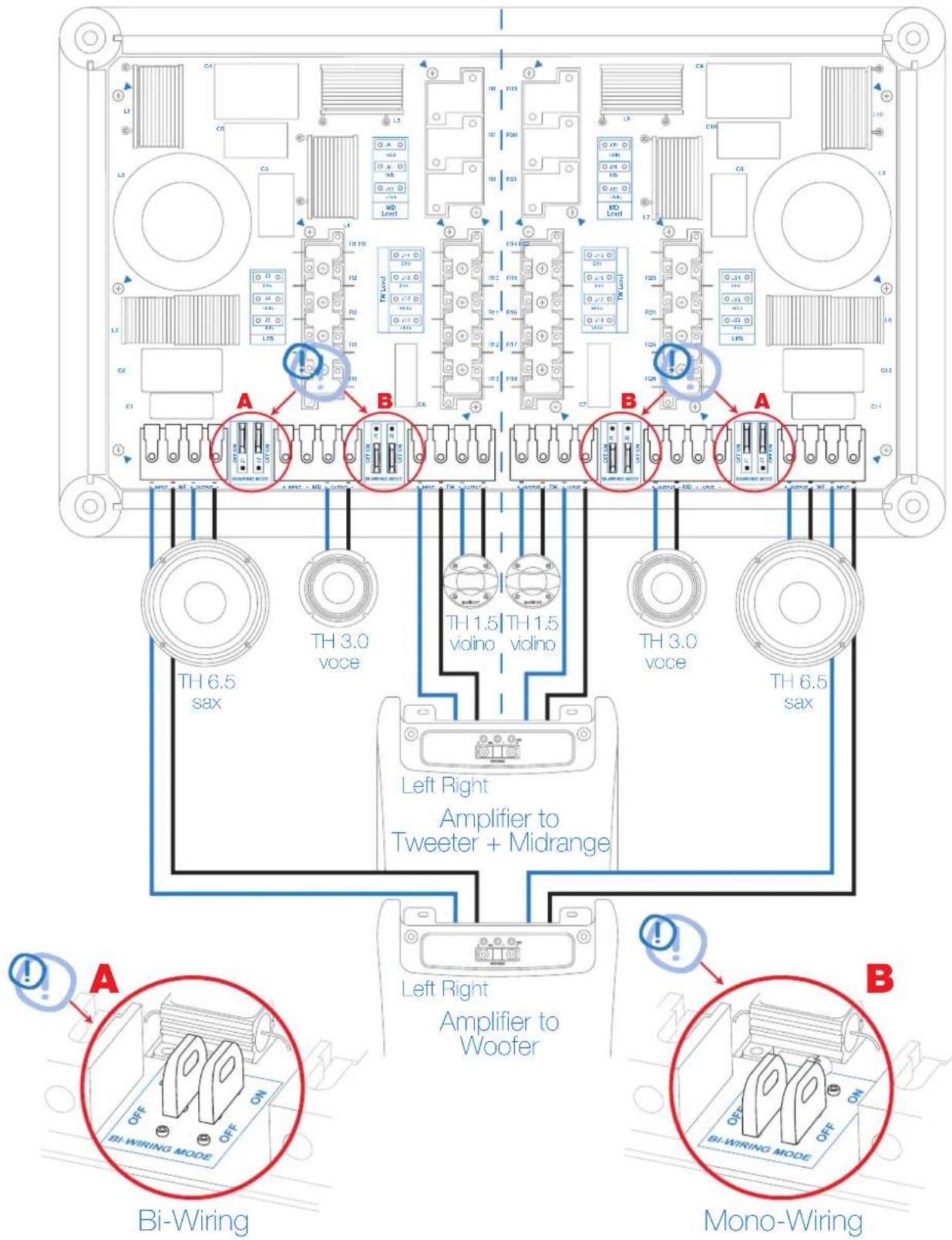
THX 3 Tri-Wiring connection
Left Channel Right Channel
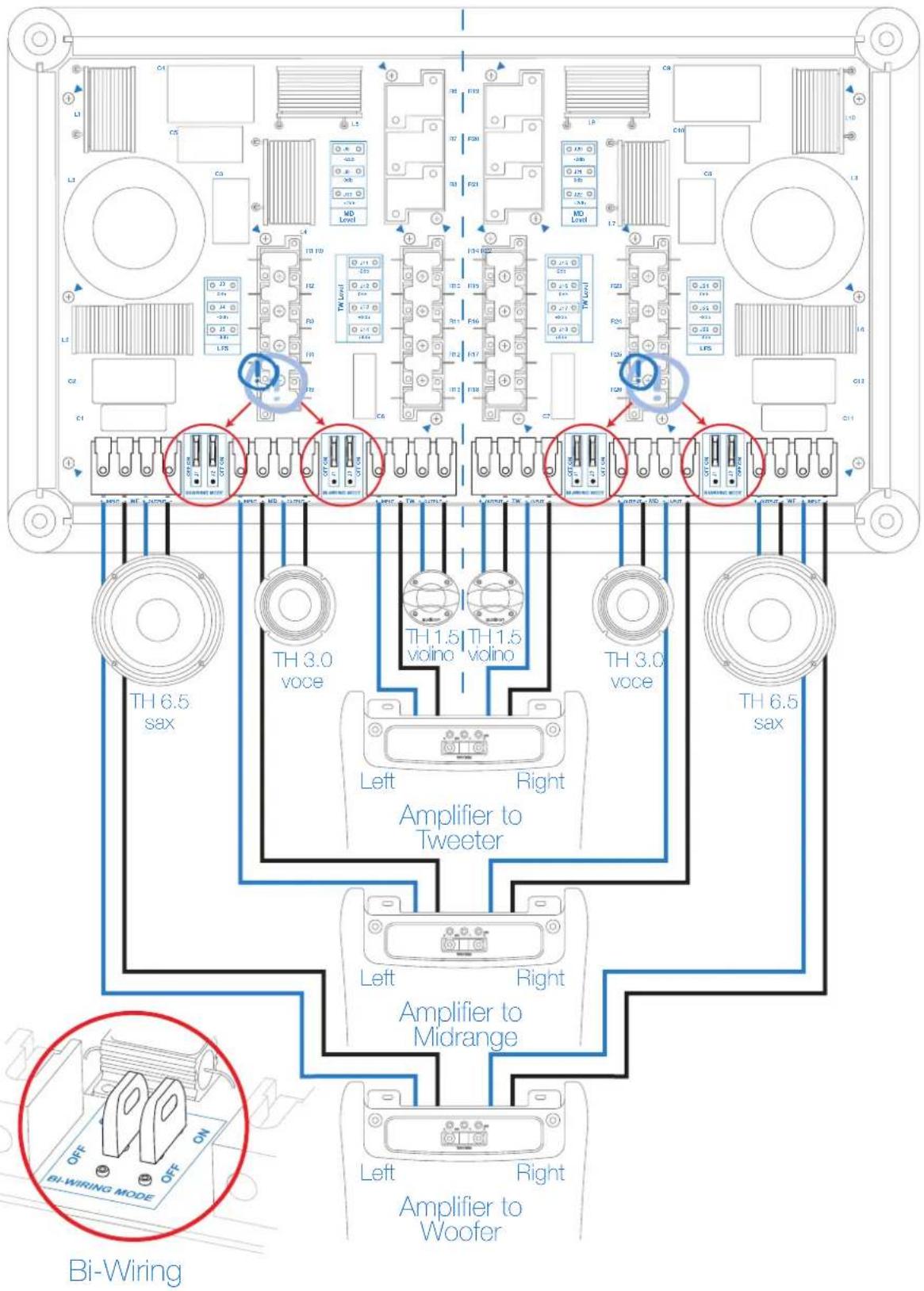
THX 3 Installation recommended with default set filter


THX 3 Installation with door mounted midrange

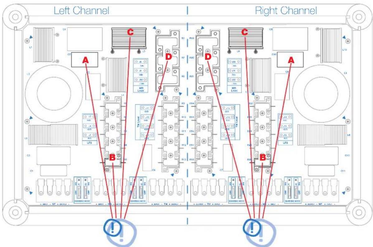
WORK ON THESE COMPONENTS! (see page 37:39)
THX 3 Installation with door mounted double woofer


WORK ON THIS COMPONENT! (see page 37÷39)
THX 3 Installation with door mounted double woofer and midrange


WORK ON THESE COMPONENTS! (see page 37÷39)
THX 3 Tweeter Level Adjustment

THX 3 Midrange Level Adjustment

THX 3 LFS (Low Frequency Shaping)
Adjusting Low Frequency Response to eliminate resonances


THESIS
THX 3 How to disassemble the circuit board
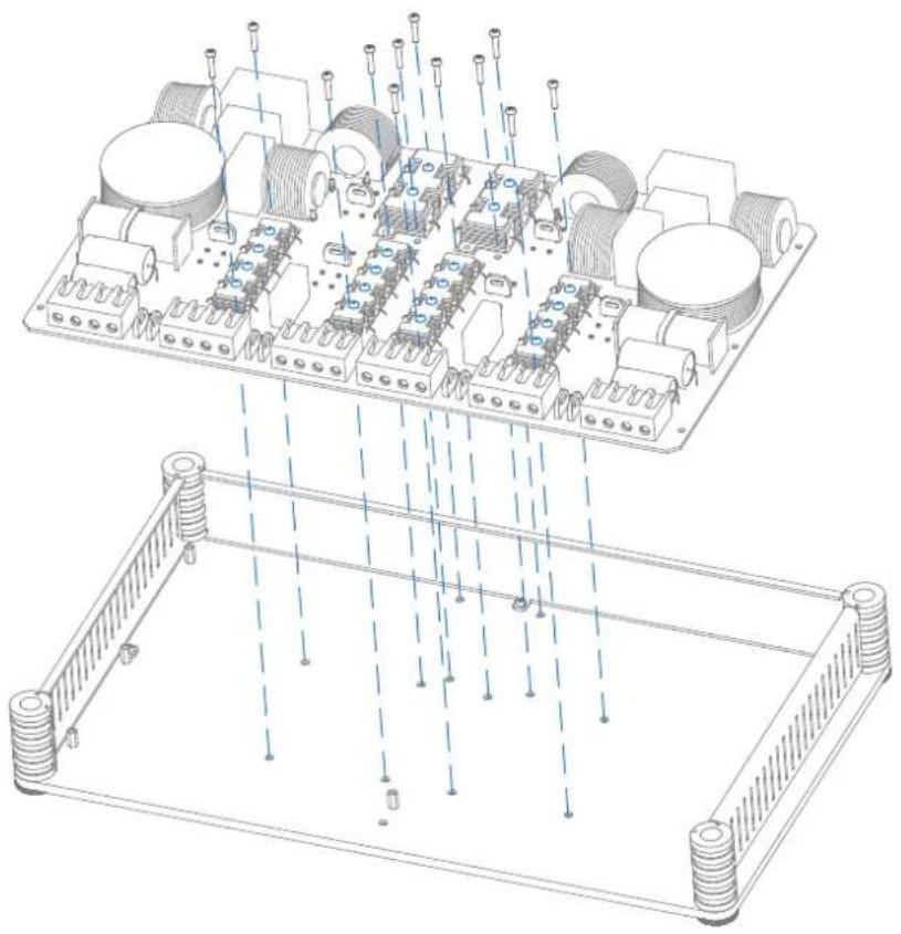
Step 1: remove plexiglass cover (see page 4)
Step 2: remove the main screws (marked in blue)


THESIS
THX 3 How to disassemble the circuit board
Step 3: remove the screws that secure the resistor blocks (marked in blue)
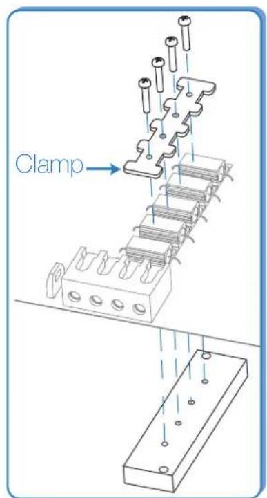
Step 4: remove the screws that secure the resistors with the clamps

THESIS
THX 3 Modifications on the single components
- Remove the screws securing the coil from the bottom of the PCB;
- Unsolder the coil leads;
- Unwind the coil with the help of an LCR meter until the value of 3,3 mH can be measured;
- Refixe the coil.

capacitor
Insert the supplied 1,5 mH coil Insert the supplied 10g Supplied
resistors originally mounted
following the diagram
on page 31 or 33
Technical Specifications
| THX 2 | THX 3 | THX mh | ||
| Type | Stereo 2 wayPassive Crossover Network | Stereo 3 wayPassive Crossover Network | Stereo 2 way Mid-HighPassive Crossover Network | |
| Size | mm / inch | 348x190x66,5 133/4 × 71/2 × 25/8 | 438x258x66,5 171/4 × 101/4 × 25/8 | 348x190x66,5 133/4 × 71/2 × 25/8 |
| Power | W peak | 400 | 400 | 400 |
| Handling | W continuous | 200 | 200 | 200 |
| Crossover frequency | LO/HI-pass | 2.5 kHz | 450 Hz / 3.5 kHz | 280 Hz / 3.5 kHz |
| Slope | dB/Oct. | 6/12 | 12/6-12/12 | 6 (ON-OFF) / 12 (default)12 (ON-OFF) / 12 (optional) |
| Thesis speaker set | TH 1.5 violino +TH 6.5 sax | TH 1.5 violino +TH 3.0 voce +TH 6.5 sax | TH 1.5 violino +TH 3.0 voce | |
| Component Adjustment | TweeterMidrange | -2; 0; +2; +4 dB | -2; 0; +2; +4 dB-2; 0; +2 dB | -2; 0; +2 dBMD Hi-pass ON/OFF(280 Hz @ 6/12 dB/Oct.) |
| Woofer | LFS 0; -2; -4 dB | LFS 0; -2; -4 dB | ||
| Sound Control | Low Frequency ShapingSpeaker Position ContourMulti-Amp ConfigurationAudison Thesis Advisor | Low Frequency ShapingSpeaker Position ContourMulti-Amp ConfigurationAudison Thesis Advisor | Low Frequency ShapingSpeaker Position ContourMulti-Amp ConfigurationAudison Thesis Advisor | |
- THESIS
- INDEX
- THX 2
- THX MH
- THX 3
- THE PROJECT
- APPROPRIATE TUNING
- OPEN DESIGN
- EXTREME CUSTOMIZATION
- AUDISON THESIS ADVISOR
- PATTERNS
- TUNING KIT (SUPPLIED)
- THX 2 BI-WIRING CONNECTION
- THX 2 INSTALLATION RECOMMENDED WITH DEFAULT SET FILTER
- THX 2 INSTALLATION WITH DOOR MOUNTED TWEETER
- THX 2 LFS (LOW FREQUENCY SHAPING)
- THX 2 HOW TO DISASSEMBLE THE CIRCUIT BOARD
- THX 2 MODIFICATIONS ON THE SINGLE COMPONENTS
- THX MH BI-WIRING CONNECTION
- THX MH INSTALLATION WITH DOOR MOUNTED MIDRANGE
- THX MH TWEETER LEVEL ADJUSTMENT
- THX MH MIDRANGE HI-PASS
- THX MH HOW TO DISASSEMBLE THE CIRCUIT BOARD
- THX MH MODIFICATIONS ON THE SINGLE COMPONENTS
- THX 3 MONO-WIRING CONNECTION
- THX 3 BI-WIRING CONNECTION
- THX 3 TRI-WIRING CONNECTION
- THX 3 INSTALLATION RECOMMENDED WITH DEFAULT SET FILTER
- THX 3 LFS (LOW FREQUENCY SHAPING)
- THX 3 HOW TO DISASSEMBLE THE CIRCUIT BOARD
- THX 3 MODIFICATIONS ON THE SINGLE COMPONENTS
Brand : AUDISON
Model : Thesis THX 2 II
Category : Audio Electronics