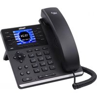
C401 - Telephone OpenVox - Free user manual and instructions
Find the device manual for free C401 OpenVox in PDF.


| Product Type | VoIP Desktop Phone |
| Model | C401 |
| Brand | OpenVox |
| Dimensions (W x D x H) | 200 mm x 180 mm x 120 mm |
| Weight | 0.8 kg |
| Power Supply | Power over Ethernet (PoE) or AC adapter (5V DC) |
| Display | 2.8-inch color LCD with backlight |
| Key Features | SIP 2.0, HD audio, 2x Ethernet ports, 4 programmable keys |
| Audio Codecs | G.711, G.722, G.729, iLBC |
| Network Protocols | TCP/IP, UDP, DHCP, DNS, NTP |
| Ports | 2x RJ45 10/100 Mbps, 1x RJ9 handset, 1x RJ9 headset |
| Operating Temperature | 0°C to 40°C |
| Storage Temperature | -10°C to 60°C |
| Relative Humidity | 10% to 90% non-condensing |
| Cleaning Instructions | Wipe with a soft dry cloth; do not use liquid cleaners |
| Safety Certifications | CE, FCC |
| Spare Parts Available | Handset, power adapter, Ethernet cable |
| Repairability | Modular design; replaceable handset and cables |
| Warranty | 1 year limited |
Frequently Asked Questions - C401 OpenVox
User questions about C401 OpenVox
0 question about this device. Answer the ones you know or ask your own.
Ask a new question about this device
Download the instructions for your Telephone in PDF format for free! Find your manual C401 - OpenVox and take your electronic device back in hand. On this page are published all the documents necessary for the use of your device. C401 by OpenVox.
USER MANUAL C401 OpenVox
OpenVox Communication Co., Ltd
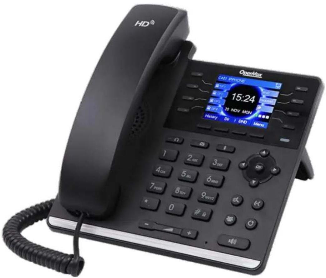
C401 User Manual\_V1.0
OpenVox
OpenVox Communication Co.,Ltd
Address: 10/F, Building 6-A, Baoneng Science and Technology Industrial Park, Longl
New District, Shenzhen, Guangdong, China 518109
Tel: +86-755-66630978, 82535461, 82535362
Business Contact: sales@openvox.cn
Technical Support: support@openvox.cn
Business Hours: 09:00-18:00(GMT+8) from Monday to Friday
URL: www.openvox.cn
Thank You for Choosing OpenVox Products!
Revision History
| Document VER | Firmware VER | Explanation | Time |
| V1.0 | |||
Content
Revision History......1
1. Safety Instruction....1
2. Overview....2
3. Installation....3
3.1 Use PoE or external Power Adapter....3
3.2 Desktop and Wall-mount Installation....4
4. Introduction to the Phone User Interface....6
4.1 Keypad....6
4.2 Using Handset / Hands-free Speaker / Headphone....7
4.3 Screen User Interface....8
4.4 Web Portal....9
5. Setting Up.... 10
5.1 Network Configuration.... 10
5.2 Line Configurations....10
6. Using the Phone....15
6.1 Making Phone Calls.... 15
6.1.1 Make / Receive Second Call.... 19
6.1.2 Join / Split Two Calls (3-way Local Conference)....20
6.1.3 Call Transfer....20
6.2 Using Phonebook.... 20
6.2.1 Add / Edit / Delete Contact....22
6.2.2 Add / Edit / Delete Group 22
6.2.3 Browse and Add / Remove Contacts in Group....23
6.3 Using Cloud Phonebook....23
6.3.1 Open Cloud Phonebook 24
6.4 Call Logs....25
6.5 Voice Message....26
6.6 Do-Not-Disturb....27
6.7 Auto-Answering....28
6.8 Call Forward....29
6.9 DSS LCD Configuration....30
7. Phone Settings....32
7.1 Adjust Audio Volume....32
7.2 Set Ring Tone Volume and Type....32
7.3 Adjust LCD Energy Saving....32
7.4 Set Device Time/Date....33
7.5 Set Device Language....34
7.6 Reboot the Device....34
7.7 Reset to Factory Default....34
8. Web Portal....35
8.1 Web Portal Authentication....35
8.2 Web Call....35
8.3 SYSTEM / Information....36
8.4 SYSTEM / Account....36
8.5 SYSTEM / Configurations....36
8.6 SYSTEM / Upgrade....36
8.7 SYSTEM / Auto Provision....37
8.8 SYSTEM / Tools....37
8.9 NETWORK / Basic....37
8.10 NETWORK / Advanced....37
8.11 NETWORK / VPN....37
8.12 LINES / SIP....37
8.13 LINES / Dial Peer....41
8.14 LINES / Dial Plan....44
8.15 LINES / Basic Settings....45
8.16 PHONE / Features....45
8.17 PHONE / Audio....47
8.18 PHONE / MCAST....48
8.19 PHONE / Time/Date....49
8.20 PHONE / Advanced....50
8.21 PHONEBOOK / Contacts....50
822 PHONEBOOK / Cloud Phonebook....50
8.23 PHONEBOOK / Blacklist....51
8.24 PHONEBOOK / Advanced....51
8.25 CALL LOGS.... 51
8.26 FUNCTION KEY / Function Key....51
8.27 FUNCTION KEY / Softkey....52
9. Advanced Features....54
9.1 VPN....54
9.1.1 L2TP....54
9.1.2 OpenVPN....54
10. Trouble Shooting....55
10.1 Get Device System Information....55
10.2 Upgrade to the latest software....55
10.3 Reboot Device....55
10.4 Reset Device to Factory Default....55
10.5 Network Packets Capture....55
10.6 Entering Post Mode and Recover System Image....56
10.7 Common Trouble Cases....56
Appendix I - Icon Illustration....58
Appendix II – Text Input from Keypad....59
Appendix III – LED Definition....61
1. Safety Instruction
Please read the following safety notices before installing or using this unit. They are crucial for the safe and reliable operation of the device.
- Please use the external power supply that is included in the package. Other power supply may cause damage to the phone, affect the behavior or induce noise.
- Before using the external power supply in the package, please check the home power voltage. Inaccurate power voltage may cause fire and damage.
- Please do not damage the power cord. If power cord or plug is impaired, do not use it, it may cause fire or electric shock.
- Do not drop, knock or shake the phone. Rough handling can break internal circuit boards.
- This phone is design for indoor use. Do not install the device in places where there is direct sunlight. Also do not put the device on carpets or cushions. It may cause fire or breakdown.
- Avoid exposure the phone to high temperature or below 0°C or high humidity.
- Avoid wetting the unit with any liquid.
- Do not attempt to open it. Non-expert handling of the device could damage it. Consult your authorized dealer for help, or else it may cause fire, electric shock and breakdown.
- Do not use harsh chemicals, cleaning solvents, or strong detergents to clean it. Wipe it with a soft cloth that has been slightly dampened in a mild soap and water solution.
- When lightning, do not touch power plug, it may cause an electric shock.
- Do not install this phone in an ill-ventilated place. You are in a situation that could cause bodily injury. Before you work on any equipment, be aware of the hazards involved with electrical circuitry and be familiar with standard practices for preventing accidents.
2. Overview
The new C401 color screen IP Phone is a high-end enterprise desktop phone which comes with intelligent LCD the DSS Key-mapping to increase enterprise users' productivity at a cost-effective price.
The DSS key-mapping is designed with intelligence to support dynamic usage to substitute expansion modules. There are 7 DSS keys corresponded to the color LCD display to provide dynamic Line/DSS/BLF functions up to four pages at virtualized total 28 DSS keys. User may configure/customize each DSS key in each page. Every DSS key has a LED indication in green, red, and yellow colors to reflect the key state. A page shortcut button is also designed to allow user to quickly switch between pages. C401 is the most economic choice for SMB office and enterprise supervisors.
C401 inherits all features from enterprise phones, such as HD voice in handset, headset, and full-duplex speakerphone modes, PoE, Fast/Gigabit Ethernet, QoS, secure transmission, auto-provisioning, and more.
C401 is a great office productivity appliance for enterprise users. The old DSS key label is inconvenient and not environmental friendly. C401's intelligent LCD the DSS Key-mapping provides users the flexibility to change DSS key definition and display through easy configuration. Meanwhile, with its intelligent design of the DSS key, it can be multiplied as expansion modules to save space and cost. C401 will provide the best user experience to advance enterprise users."
In order to help some users who are interested to read every detail of the product, this user manual is provided as a user's reference guide. Still, the document might not be up to date with the newly release software, so please kindly download updated the latest user manual from website, or contact with support if you have any question using C401.
3. Installation
3.1 Use PoE or external Power Adapter
C401, called as 'the device' hereafter, supports two power supply modes, power supply from external power adapter and C401 supports 802.3af Class 2 Power over Ethernet (PoE) complied switch.
PoE power supply saves the space and cost of providing the device additional power outlet. With a PoE switch, the device can be powered through a single Ethernet cable which is also used for data transmission. By attaching UPS system to PoE switch, the device can keep working at power outage just like traditional PSTN telephone which is powered by the telephone line.
For users who do not have PoE equipment, the traditional power adapter should be used. If the device is connected to a PoE switch and power adapter at the same time, the power adapter will be used in priority will switch to PoE power supply at power failure on the power adapter.
Please use the power adapter supplied and the PoE switch met the specifications to ensure the device worked properly.
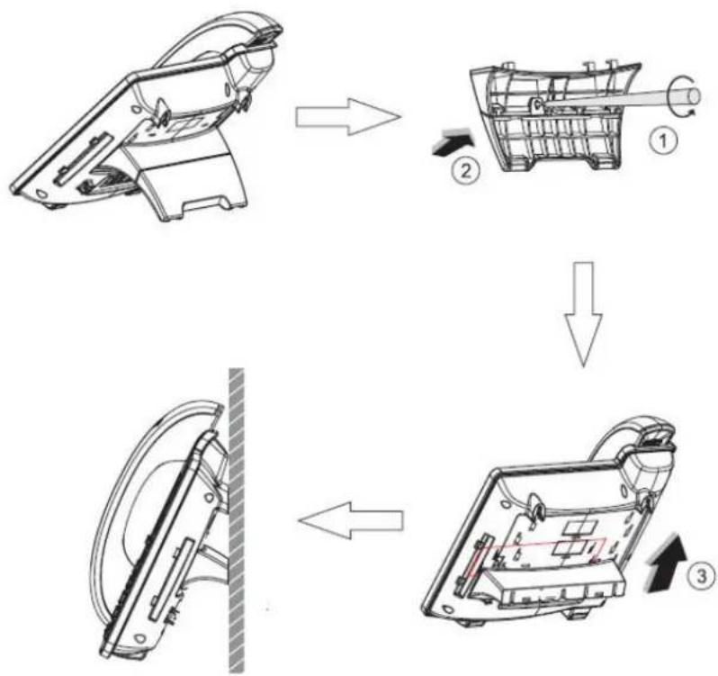
3.2 Desktop and Wall-mount Installation
The device supports two installation mode, desktop and wall-mount. To set up the phone to be used on desktop, please follow the instructions in below picture to install the device.

Figure 1 - Desktop Installation
To mount the device on the wall, please follow the instructions in below picture.
flowchart
graph TD
    A["Initial battery housing"] --> B["Step ①: Internal component with rotation arrow"]
    B --> C["Step ②: Internal component with clockwise arrow"]
    C --> D["Step ③: Final motor assembly with directional arrows indicating assembly steps"]
Figure 2 - Wall-mount Installation
Please connect power adapter, network, PC, handset, and headphone to the corresponding ports as described in below picture.
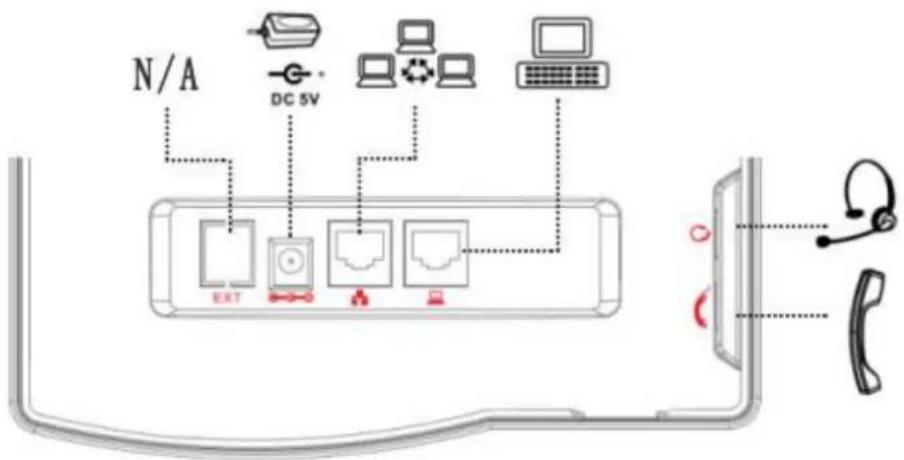
Figure 3 - Connecting to the Device
NOTICE: Power adapter is optional for C401 model.
4. Introduction to the Phone User Interface
4.1 Keypad

Figure 4 - Keypad
The above picture shows the keypad layout of the device. Each key provides its own specific function. User should refer to the illustration in this section about the usage of each key and the description in this document about each function.
Some keys support long-pressing function. User can press and hold the key for 1.5 seconds to trigger the long-pressed function.
● DSS keys - You could customize these DSS keys with some preset functions.
- LCD page switch key - You could switch the LCD pages by pressing the key.
- Soft Keys – These four buttons provide different functions corresponding to the soft-menu displayed on the screen.
● Power key - The key will green flash when the phone reboot with power supply.
● Headset key - When you pressed the key, you could make a call using the headset.
● MWI key - You could view the voice messages by pressing the key.
● Mute key - Mute you phone. you can also mute the microphone with this button during talking mode.
- Navigation Keys – User can press up/down navigation keys to change line focus in talking screen or move cursor in a screen with list items; in some configuration or text editor screen, user can press left/right navigation keys to switch option or move cursor to the left / right.
- Numeric Keys – The 12 standard telephone keys provide the same function as standard telephones, but
further to the standard function, some keys also provide special function by long-pressing the key.
Key # - Long-pressed to lock the phone. (Default PIN is 123)
Key Page - Long-pressed to open LCD page configuration.
- Hold key - you could hold a call by pressing the key.
- Transfer key - You could transfer a call by pressing the key.
● Conference key - You could invite a third part to join your call by pressing the key. - Redial – By pressing ‘Redial’ button, user can redial the last dialed number.
- Volume -/+key – In standby, ringing, ring configuration screen, user can press 2 buttons to lower/increase the ringtone volume, in talking and audio volume adjustment screen, user can press this button to lower/increase the audio volume.
- Speaker – By pressing this button once, user can turn on the audio channel of hands-free speaker
4.2 Using Handset / Hands-free Speaker / Headphone
- Using Handset
To talk over handset, user should lift the handset off the device and dial the number, or dial the number first then lift the handset and the number will be dialed. User can switch audio channel to handset by lifting the handset when audio channel is opened in speaker or headphone.
● Using Hands-free Speaker
To talk over hands-free speaker, user should press the hands-free button then dial the number, or dial the number first then press the hands-free button. User can switch audio channel to the speaker from handset by pressing the hands-free button when audio channel is opened in handset.
- Using Headphone
To use headphone, by default, user should headset button which is defined by DSS key to turn on the headphone. Same as handset and hands-free speaker, user can dial the number before or after headphone turned on.
● Using Line Keys(Defined by DSS Key)
User can use line key to make or answer a call on specific line. If handset has been lifted, the audio channel will be opened in handset, otherwise, the audio channel will be opened in hands-free speaker or headphone.
4.3 Screen User Interface
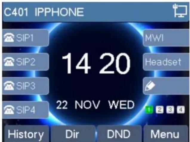
Figure 5 - Screen Layout / Default Standby Screen
The screen user interface is mostly presented in the above layout except some prompt messages. The upper area is the main screen to display the device's status and information or data for viewing or editing. The low area is the software menu (soft-menu) buttons which will change against user's action or device's status.
The above picture shows the default standby screen which is also the root of the soft-menu. The default standby screen shows the greeting words and effective feature indications like voice message, missed call, auto-answering, do-not-disturb, call forward, lock state, and the network connectivity. User can get back to the default standby screen mostly by lifting and putting by the handset.
The icon illustration is described in Appendix I - Icon Illustration.
In some screens, there are more items or long text to be displayed which could not fit into the screen. They will be arranged in a list or multiple lines with a scroll bar. If user sees a scroll bar, user can use up/down navigation buttons to scroll the list. By long-pressed the navigation keys, user can scroll the list or items in a faster speed.

Figure 6 - Vertical Scroll Bar
4.4 Web Portal
User can also use the device's web portal to manage or operate the device. User should open the device's web portal page by entering the device's IP address in a browser. To get the device IP address, user could press the soft-menu button [Menu] -> [Status] or by pressing [Down] navigation key.

Figure 7 - Check the Device's IP Address
The first screen of the device's web portal is the login page.

Figure 8 - Web Portal Login Page
User must enter the username and password to log in to the web portal. The default username and password are both 'admin'. For the detail of web portal operations, please refer to 8 Web Portal.
5. Setting Up
In order to get the device ready for making and receiving phone calls, the device must be configured with correct network configurations and at least one of the lines must be configured with an SIP telephony service
5.1 Network Configuration
The device relies on IP network connection to provide service. Unlike traditional phone system based on a circuit switched wire technology, IP devices are connected to each other over the network and exchange data in packet basis based on the devices' IP address.
To enable the device, the network parameters must be configured properly first. To configure network parameters, user should open the network configuration screen through soft-menu [Menu] -> [Settings] -> [Advanced Settings] -> [Network] -> [Network Settings] from standby screen.
NOTICE: If user saw a ‘Network Disconnected’ icon flashing in the middle of screen, it means the
network cable was not correctly connected to the device's network port. Please check the cable is connected correctly to the device and to the network switch, router, or modem.
There are three common IP configuration modes.
- Dynamic Host Configuration Protocol (DHCP) – This is the automatic configuration mode by getting network configurations from a DHCP server. Users need not to configure any parameters manually. All configuration parameters will be getting from DHCP server and applied to the device. This is recommended for most users.
- Static IP Configuration – This option allows user to configure each IP parameters manually, including IP Address, Subnet Mask, Default Gateway, and DNS servers. This is usually used in an office environment or by power users.
- PPPoE – This option is often used by users who connect the device to a broadband modem or router. establish a PPPoE connection, user should configure username and password provided by the service provider.
The device is default configured in DHCP mode.
5.2 Line Configurations
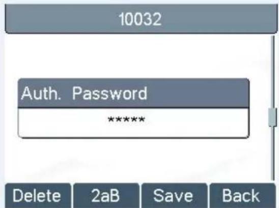
A line must be configured properly to be able to provide telephony service. The line configuration is like a virtualized SIM card. Just like a SIM card on a mobile phone, it stores the service provider and the account information used for registration and authentication. When the device is applied with the configuration, it will register the device to the service provider with the server's address and user's authentication as stored in the configurations.
To configure a line manually, user may open the line configuration screen through soft-menu button [Menu] -
[Settings] -> [Advanced Settings] -> [Accounts] -> [SIP1] / [SIP2] / [SIP3] / [SIP4] -> [Basic Settings] from the standby screen.
NOTICE: User must enter correct PIN code to be able to enter advanced settings to edit line configuration. (The default PIN is 123)
The parameters and screens are listed in below pictures.

Figure 9 - Configure SIP Proxy Server Address

flowchart
graph TD
    A["10032"] --> B["Auth. User"]
    B --> C["10032_"]
    C --> D["Delete"]
    C --> E["2aB"]
    C --> F["Save"]
    C --> G["Back"]
Figure 12 - Configure Authentication Name

Figure 10 - Configure SIP Proxy Server Po
flowchart
graph TD
    A["Auth. Password"] --> B["********"]
    C["Delete"] --> D["2aB"]
    E["Save"] --> F["Back"]
Figure 13 - Configure SIP Authentication Password

flowchart
graph TD
    A["Username"] --> B["10032"]
    C["Delete"] --> D["2aB"]
    E["Save"] --> F["Back"]
Figure 11 - Configure SIP Username

Figure 14 - Configure Display Name

Figure 15 - Enable / Disable Outbound Pro
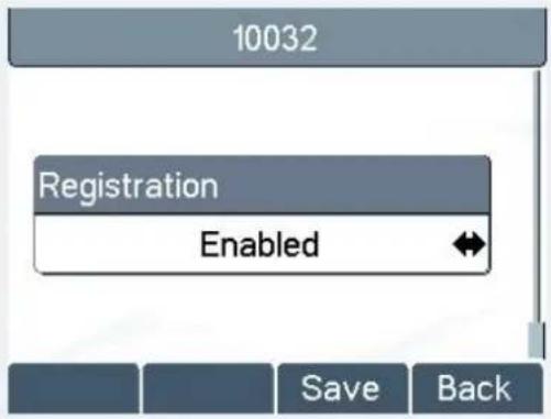
Figure 16 - Enable / Disable Sip Line
Save the adjustment by pressing [OK] or [Save] button when done.
For users who want to configure more options, user should use web management portal to modify or Advanced Settings in accounts on the individual line to configure those options.

Figure 17 - Configure Advanced Line Options

flowchart
graph TD
    A["10032"] --> B["Domain Realm"]
    B --> C["Delete"]
    B --> D["2aB"]
    B --> E["Save"]
    B --> F["Back"]
Figure 18 - Configure SIP Realm/Domain

Figure 19 - Configure Unregistered Dial

Figure 20 - Enable / Disable Anonymous

Figure 21 - Configure DTMF Mode

Figure 22 - Enable / Disable STUN

flowchart
graph TD
    A["10032"] --> B["Local Port"]
    B --> C["5060"]
    C --> D["Delete"]
    C --> E["Save"]
    C --> F["Back"]
Figure 23 - Configure Local Port

Figure 24 - configure Ring Type

Figure 25 - Configure MWI Number

flowchart
graph TD
    A["10032"] --> B["Pickup Number"]
    B --> C["999_"]
    D["Delete"] --> E["123"]
    F["Save"] --> G["Back"]
Figure 26 - Configure Pickup Number

Figure 27 - Configure Park Number

Figure 28 - Configure Join Call Number

Figure 30 - Enable / Disable Feature Sync

Figure 29 - Enable / Disable Missed Call
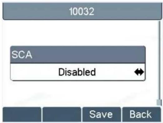
Figure 31 - Enable / Disable SCA
NOTICE: On the device, user can only configure whether STUN / Outbound Proxy is enabled, to change the STUN / Outbound Proxy server address, user must edit in the device web portal. (Refer to 8.15 LINES / Global Settings and 8.12 LINES / SIP )
6. Using the Phone
6.1 Making Phone Calls
- Default Line
The device provides 4 line services. If all lines are configured, user can make or receive phone calls on any line. If default line is configured by user, there will be a default line to be used for making outgoing call which is indicated on the top left corner. To change the default line, user can press up/down navigation buttons to switch between all lines. Enable or disable default line, user can press [Menu] -> [Features] -> [Default Line or configure from Web Interface (Web / Phone settings / Features).
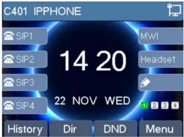
Figure 32 - Default Line
- Dialing Methods
User can dial a number by,
➢ Entering the number directly
➢ Selecting a phone number from phonebook contacts (Refer to 6.2 Using Phonebook)
➢ Selecting a phone number from cloud phonebook contacts (Refer to 6.3 Using Cloud Phonebook)
Selecting a phone number from call logs (Refer to 6.4 Call Logs)
➢ Redialing the last dialed number
- Dialing Number then Opening Audio
To make a phone call, user can firstly dial a number by one of the above methods. When the dialed number completed, user can press [Dial] button on the soft-menu, or press hand-free button to turn on the speaker (headphone, or lift the handset to call out with the current line, or user can press line key (Configured by DS: keys) to call out with specified line.

Figure 33 - Dialing a Number before Audio Channel Opened
- Opening Audio then Dialing the Number
Another alternative is the traditional way to firstly open the audio channel by lifting the handset, turning on the hands-free speaker or headphone by pressing hands-free button, or line key, and then dial the number with one of the above methods. When number dialed completed, user can press [Dial] button or [OK] button to c out, or the number will be dialed out automatically after timeout.

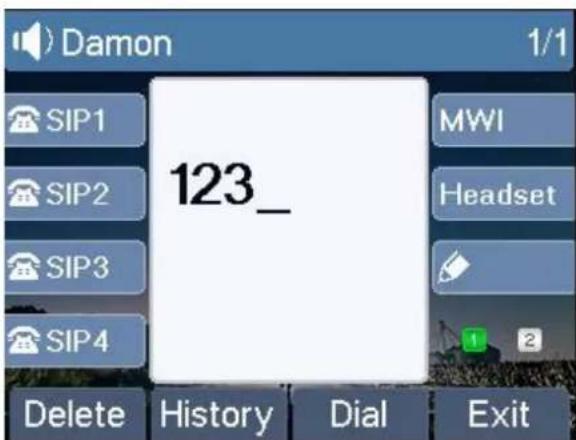
Figure 34 - Dial a Number after Audio Channel Opened
NOTICE: For some users who get used to dial a number immediately by pressing #key, the user must login to the web to enable 'Press "#" to invoke diapitign in page [Line] -> [Dial Plan] -> "Basic Settings" and apply it.
- Cancel Call
While calling the number, user can press [End] button or close the audio channel by put back the handset or press the hands-free button to drop the call.
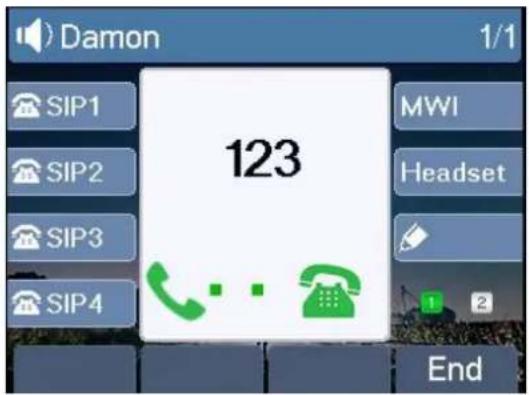
Figure 35 - Calling Remote Party
- Answering Incoming Call
When there is an incoming call while the device is idle, user will see the following incoming call alerting screen
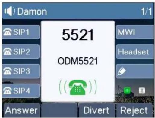
Figure 36 - Incoming Call Screen
User can answer the call by lifting the handset, open headphone or speaker phone by pressing the hands-free button, or the [OK] / [Answer] button. To divert the incoming call, user should press [Divert] button. To reject the incoming call, user should press [Reject] button.
- Talking
When the call is connected, user will see a talking mode screen as the following figure.

Figure 37 - Talking Mode Screen
- Audio Channel – The icon reflects the current audio channel being used.
- Current Line - The line is being used on the call.
- Remote Party – The name or number of the remote party.
- Talking time – The time passed since the call established.
- Screen Pages – The number of screen pages. User can press up/down navigation buttons to switch screen page.
- Call Holding /Resuming
User can hold the remote party by pressing [Hold] button and the button will be changed to [Resume] icon. User can press the [Resume] button to resume the call.
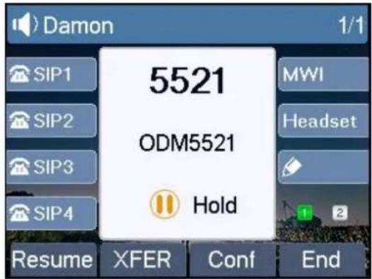
Figure 38 - Call Holding Screen
- Call Ended
When user finished the call, user can put the handset back to the device to hang up the call or press the hands-free button to close the audio channel to hang up.
NOTICE: When the call is held or in holding state, the user press [Resume] button to back to call mode, or putting the handset back to the device or pressing a key-free button to hang up is not available.
6.1.1 Make / Receive Second Call
The device can support up to multichannel concurrent calls. When there is already a call established, user can still answer another incoming call on either lines or make a second call on either lines.
- Second Incoming Call
When there is another incoming call during talking a phone call, this call will be waiting for user to answer if User will see the call message in the middle of current screen. The device will not be ringing but playing call waiting tone in the audio channel of the current call and the LED will be flashing in green. User can accept reject the call same as normal incoming call. When the waiting call is answered, the first call will be put on hold automatically.

Figure 39 - Second Incoming Call Screen
- Second Outgoing Call
To make a second call, user may press [XFER] / [Conf] button to make a new call on the default line or p the line key to make new call on specific line. Then dial the number the same way as making a phone call Another alternative for making second call is to pressing DSS Keys dial out from the configured keys (BLF / Speed Dial). When user is making a second call with the above methods, the first call could be place on how manually first or will be put on hold automatically at second dial.
- Switching between Two Calls
When there are two calls established, user will see a dual calls screen as the following picture

Figure 40 - Dual Calls
User can press up/down navigation buttons to switch screen page, and switch call focus by pressing [Hold] / [Resume] button.
- Ending One Call
User may hang up the current talking call by closing the audio channel or press [End] button. The device w
return to single call mode in holding state.
6.1.2 Join / Split Two Calls (3-way Local Conference)
In the dual call mode, user can join two calls into a conference call by pressing [Conf] button. When two calls are joined, user can split them by pressing [Split] button.

Figure 41 - Conference Call
6.1.3 Call Transfer
When the user is talking with a remote party and wish to transfer the call to another remote party, there are two way to transfer the call, attended and unattended.
- Attended Transfer
The attended call transfer is also known as the 'polite mode' which is to dial through the other remote party wait for the remote party to answer the call and then transfer the call.
This is the same procedure as making two concurrent calls. In the dual call mode, press the [XFER] button transfer the first party to the second one.
● Unattended / Blind Transfer
Unattended transfer is also known as 'Fire and Forget' mode. Instead of connecting to the second party first and confirming the second call is established, user press [XFER] button first then dial the second party number. When the number is dialed, user can press[XFER] button again and the first party will be transfer to the second.
This is like helping the first party to dial to the second one. However, the transfer could be successful if the second party answered it, or could be failed if the second party is busy or rejected it.
NOTICE: More advanced transfer configuration, please refer to 8.14 LINES / Dial Plan.
6.2 Using Phonebook
User can save contacts' information in the phonebook and dial the contact's phone number(s) from the phonebook. To open the phonebook, user can press soft-menu button [Dir] in the default standby screen or keypad.
By default the phonebook is empty, user may add contact(s) into the phonebook manually or from call logs.

Figure 42 - Phonebook screen
NOTICE: The device can save up to total 500 contact records.

Figure 43 - Phonebook is Empty
When there are contact records in the phonebook, the contact records will be arranged in the alphabet order. User may browse the contacts with up/down navigation keys. User may fast scroll the contact list by holding the up/down navigation keys. The record indicator tells user which contact is currently focused. User may check the contact's information by pressing [OK] button.

Figure 44 - Browsing Phonebook
6.2.1 Add / Edit / Delete Contact
To add a new contact, user should press [Add] button to open Add Contact screen and enter the contact information of the followings.
- Contact Name
- Tel. Number
- Mobile Number
- Other Number
- Ring Tone
- Contact Group
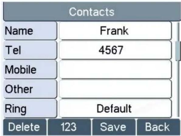
Figure 45 - Add New Contact
User can edit a contact by pressing [Option] -> [Edit] button.
To delete a contact, user should move the record indicator to the position of the contact to be deleted, pres [Option] -> [Delete] button and confirm with [Yes].
6.2.2 Add / Edit / Delete Group
User can open the group list by pressing [Groups] button in phonebook screen.
By default, the group list is blank. User can create his/her own groups, edit the group name, add or remove contacts in the group, and delete a group.
To add a group, press [Add] button.
To delete a group, press [Option] -> [Delete] button.
To edit a group, press [Edit] button.

Figure 46 - Group List
6.2.3 Browse and Add / Remove Contacts in Group
User can browse contacts in a group by opening the group in group list with [OK] button.

Figure 47 - Browsing Contacts in a Group
When user is browsing contacts of a group, user can also add or remove contacts in that group by pressing [Add] button to enter the group contacts management screen. Press [Add] button to create a new contact for the group; press [Option] button to remove the contact from the group.

Figure 48 - Add/Remove Contacts in a Group
6.3 Using Cloud Phonebook
Cloud phonebook allows user to configure the device to download a phonebook from a cloud server. This is
very useful for office users to use the phonebook from a single source and save the effort to create and maintain the contact list individually. It is also a useful tool for user to synchronize his/her phonebook from a personal mobile phone to the device with Cloud Phonebook Service and App which is to be provided publicly soon.
NOTICE: The cloud phonebook is ONLY temporarily downloaded to the device each time it is opened on the device to ensure the user get the most up to date phonebook. However, the downloading may take a couple seconds depending on the network condition. Therefore, it is highly recommended to the users to save important contacts from cloud to local phonebook to save the time of waiting for downloading.
To open cloud phonebook list, press [Cloud Phonebook] in phonebook screen.
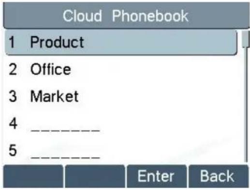
Figure 49 - Cloud Phonebook List
6.3.1 Open Cloud Phonebook
In cloud phonebook screen, user can open a cloud phonebook by pressing [OK] / [Enter] button. The device will start downloading the phonebook. If downloading failed, user will be prompted with a warning message. Once the cloud phonebook is downloaded completed, user may browse the contact list and dial the contact number same as in local phonebook.

Figure 50 - Downloading Cloud Phonebook

Figure 51 - Browsing Contacts in Cloud Phonebook
6.4 Call Logs
The device can store up to 600 call log records and user can open the call logs to check all incoming, outgoing, and missed call records by pressing soft-menu button [History]
In the call logs screen, user may browse the call logs with up/down navigation keys.
Each call log record is presented with 'call type' and 'call party number / name'. User can check further call log detail by pressing [OK] button and dial the number with [Dial] button, or add the call log number to phonebook with pressing [Option] -> [Add to Contact].
User can delete a call log by pressing [Delete] button and can clear all call logs by pressing [Clear] button.

Figure 52 - Call Logs
User can also filter call logs with specific call log type to narrow down the call log records by pressing the left/right navigation button and select one of the call log types in the soft-menu buttons.

- Missed Calls

- Received Calls / Incoming Calls

- Dialel Calls / Outgoing Calls
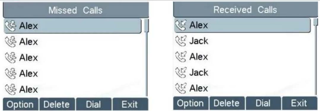
Figure 53 - Filter Call Log Type
6.5 Voice Message
If the service of the lines supports voice message feature, when the user is not available to answer the call the caller can leave a voice message on the server to the user. User will receive voice message notification from the server and device will prompt a voice message waiting icon on the standby screen.

Figure 54 - New Voice Message Notification
To retrieve the voice messages, user must configure the voice message number first. Once the voice message number is configured, user can retrieve the voice message of a line by pressing the [Dial] button in the voice message screen.
When the device is in the default standby mode.
- You can press [Menu] / [Applications] / [Voice Massage] to enter MWI interface
- When you opened voice message configuration interface, select the line to be configured with up/down navigation keys.
- Press [Edit] button to enable and edit the voice message number, when done, press [OK] / [Save] button to save the configuration.
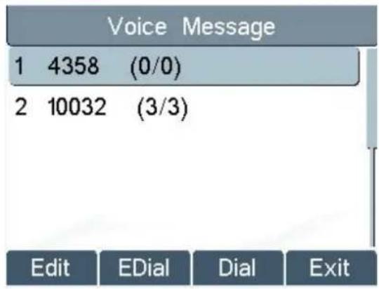
Figure 55 - Voice Message Screen
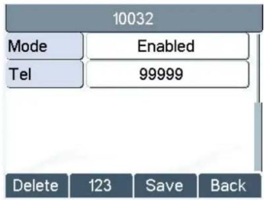
Figure 56 - Configure the Voice Message Number
6.6 Do-Not-Disturb
User may enable Do-Not-Disturb (DND) feature on the device to reject incoming calls (including call waiting). The DND can be enabled on line basis.
To quickly enable or disable the DND on all lines.
When the device is in the default standby mode.
- Press [DND] button to enable DND on all line and icon will be displayed on the screen.
- Press [DND] button again to disable DND on all line and icon will be disappeared.

Figure 57 - DND Enabled on All Lines
If user wishes to enable or disable DND on a specific line, user could change the DND mode in DND configurations.
- Press soft-button [Menu] till you find the [Features] item.
- Enter [Features] item till you find the [DND] item.
- Enter [DND] item till you find [DND item.
- Press left/right navigation key to change the DND mode or DND state on specific line. When done, press [Save] button to save the changes.
- User will see icon Do Not Disturb' against the enabled line.

Not Disturb' against the enabled line.

Figure 58 - Configure DND on Line
6.7 Auto-Answering
User may enable auto-answering feature on the device and any incoming call will be automatically answered (not including call waiting). The auto-answering can be enabled on line basis.
When the device is in the default standby mode, if user wishes to enable or disable auto-answering on a specific line or change the auto-answering delay time, user could change the auto-answering configuration adopt following steps.
- Press soft-button [Menu] till you find the [Features] item.
- Enter [Features] item till you find the [Auto Answer] item.
- Enter [Auto Answer] item to change the auto-answering configuration on a specific line
- Press left/right navigation button to select the auto-answering option. When done, press [Save] button to save the changes.
● The default auto-answering delay is 5 seconds.


Figure 59 - Configure Auto-answering on Line1

Figure 60 - Auto-answering Enabled on Line1
6.8 Call Forward
Call forward is also known as 'Call Divert' which is to divert the incoming call to a specific number based on the conditions and configurations. User can configure the call forward settings of each line.
There are three types.
- Unconditional Call Forward – Forward any incoming call to the configured number.
- Call Forward on Busy – When user is busy, the incoming call will be forwarded to the configured number.
- Call Forward on No Answer – When user does not answer the incoming call after the configured delay time, the incoming call will be forwarded to the configured number.
To configure call forward, when the device is in the default standby mode,
- Press soft-button [Menu] till you find the [Features] item.
● Enter [Features] item till you find the [Call Forward] item. - Press [Call Forward] button to open call forward configuration screen, select the line to be configured with up/down navigation keys.
- Press [Enter] button to edit the call forward settings.
- Select the call forward type with up/down navigation keys. Click [Enter] button to configure the call forward number and delay time, if applicable.
● Enable or Disable call forward with left/right navigation buttons against specific lines and types. - If select 'Enable', browse the setting parameters with up/down navigation keys and enter required information. When done, press [Save] / [OK] button to save the changes.
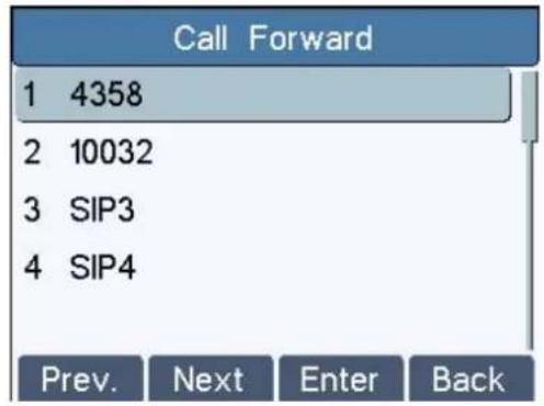
Figure 61 - Select Line for Call Forward Configuration

Figure 63 - Activate Call Forward and configure Call Forward Number

Figure 62 - Select Call Forward Type

Figure 64 - Set Delay Time for Call Forward on No Answer
6.9 DSS LCD Configuration
There are 7 DSS keys corresponded to the LCD display to provide dynamic Line/DSS/BLF functions up to four pages at virtualized total 30 DSS keys. User may configure/customize each DSS key in each page. User can enter the DSS Key page configuration by long-press DSS page key, where user can Delete/Add page(s) for the DSS LCD. Besides, user can modify DDS key configuration by long-press each one.

Figure 65 - DSS Page Configuration Screen
The phone provide DSS Key configuration, such as.
Memory Key
■ Speed Dial/Intercom/BLF/Presence/Call Park/Call Forward(For someone)
◆ Line
Key Event
■ MWI/DND/Hold/Transfer/Phonebook/Redial/Pickup/Call Forward(for entitle line)
DTMF
URL
◆ BLF List Key
Multicast
BLF/Intercom/Speed Dial number can match contact intelligently as the label, which is stored in phonebook, and DSS LCD will display the contact name rather than extension number. Moreover, user also can add the user-defined title for the DSS Keys, which is configured as Memory Key / Line / URL / Multicast .
NOTICE: User-defined title is limited to 15 characters at most.
More detailed information refers to 8.26 FUNCTION KEY / Function Key and Table 13 - Look-up Table of Characters.


Figure 66 - DSS Key Page Configuration
7. Phone Settings
7.1 Adjust Audio Volume
When the device is in the default standby mode,
- Press soft-button [Menu] till you find the [Settings] item.
● Enter [Settings] item till you find the [Basic Settings] item. - Enter [Basic Settings] item till you find [Voice Volume] item.
- Enter [Voice Volume] item and you will find [Handset Volume],[Handsfree Volume] and [Headset Volume] item.
- Enter [Handset Volume] or [Handsfree Volume] or [Headset Volume] item, press Left / Right navigation keys to adjust the audio volume for different mode.
- Save the adjustment by pressing [OK] or [Save] button when done.
7.2 Set Ring Tone Volume and Type
When the device is in the default standby mode,
- Press soft-button [Menu] till you find the [Settings] item.
- Enter [Settings] item till you find the [Basic Settings] item.
- Enter [Basic Settings] item till you find [Ring Settings] item.
● Enter [Ring Settings] item and you will find [Ring Volume] and [Ring Type] item.
■ Enter [Ring Volume] item and you find [Headset Volume] and [Handsfree Volume] item.
◆ Enter [Headset Volume] or [Handsfree Volume] item, press left / right navigation keys to adjust the ring volume.
◆ Save the adjustment by pressing [OK] button when done.
■ Enter [Ring Type] item, press left / right navigation keys to change the ring type.
◆ Save the adjustment by pressing [OK] button when done.
7.3 Adjust LCD Energy Saving
When the device is in the default standby mode.
- Press soft-button [Menu] till you find the [Settings] item.
- Enter [Settings] item till you find the [Basic Settings] item.
- Enter [Basic Settings] item till you find [Screen Settings] item.
- Enter [Screen Settings] item till you find [Energysaving] item.
● Enter [Energysaving] item, press Left / Right navigation keys to adjust the LCD Energysaving mode. - If select 'Enabled', browse the setting parameters with up/down navigation keys and enter required information. When done, press [Save] / [OK] button to save the changes.
● The default Energysaving time is 30 seconds.
7.4 Set Device Time/Date
When the device is in the default standby mode,
- Press soft-button [Menu] till you find the [Settings] item.
- Enter [Settings] item till you find the [Basic Settings] item.
- Enter [Basic Settings] item till you find [Time & Date] item.
- Enter [Time & Date] item, use up/down navigation keys to edit the time/date parameters and save the settings by pressing [OK] or [Save] button when done.
Table 1 - Time Settings Parameters
| Parameters | Description |
| Mode | Auto/ManualAuto: Enable network time synchronization via SNTP protocol, default enabled.Manual: User can modify data manually. |
| SNTP Server | SNTP server address |
| Time zone | Select the time zone |
| Daylight Saving Time | Enable or Disable the Daylight Saving Time |
| 12-Hour Clock | Display the clock in 12-hour format |
| Time format | Select time format from one of the followings:■ 1 JAN, MON■ 1 January, Monday■ JAN 1, MON■ January 1, Monday■ MON, 1 JAN■ Monday, 1 January■ MON, JAN 1■ Monday, January 1■ DD-MM-YY■ DD-MM-YYYY■ MM-DD-YY■ MM-DD-YYYY■ YY-MM-DD■ YYYY-MM-DD |
| Date(Only Mode=Manual) | Edit the date of the device in the format of yyyy/mm/dd. |
| Time(Only Mode=Manual) | Edit the time of the device in the format of hh:mm:ss. Hh=00~23, mm=00~59, ss=00~59 |
7.5 Set Device Language
When the device is in the default standby mode.
- Press soft-button [Menu] till you find the [Settings] item.
- Enter [Settings] item till you find the [Basic Settings] item.
- Enter [Basic Settings] item till you find [Language] item.
- User can change the language by using the navigation keys.
7.6 Reboot the Device
When the device is in the default standby mode,
- Press soft-button [Menu] till you find the [Reboot System] item.
- Press [OK] or [Enter] button, a warning message "Reboot Now?" will be prompt to user.
- Press [Yes] or [OK] button to execute the reset command, or [No] to exit.
7.7 Reset to Factory Default
When the device is in the default standby mode,
- Press soft-button [Menu] till you find the [Settings] item, and press [OK] or [Enter] button.
● Enter [Advanced Settings] item, then input the device PIN (Default PIN is 123) to enter the interface. - Enter [Reset to Default] item, then a warning message "Factory Reset, Continues?" will be prompt to user.
- Press [Yes] or [OK] button to execute the reset command, or [No] to exit.
8. Web Portal
8.1 Web Portal Authentication
User can log in onto the device web portal to manage the device or user's profile. User must provide correct username and password to be able to log in.
8.2 Web Call
Besides making and receiving phone calls by operating the device directly, user could also making and receiving phone calls by operating the controls in the web portal.
The web call is particularly suitable for users who use headphone. User can dial out a number by click the [Dial] button on top of the title of the web portal page, or click a contact in the phonebook, or click a numt the call logs, to make phone call and press [Answer] button to answer incoming call. When call ended, user can click [Hang up] button to end the call. All these operation can be done from the web portal without touching the phone.
NOTICE: The web call is limited to make a single call. To make or answer a second call is not allowed.
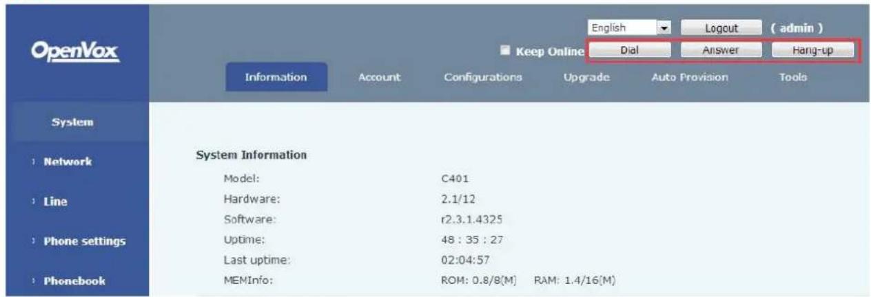
Figure 67 - Web Call Controls

Figure 68 - Web Call, Entering Number and Select Line
8.3 SYSTEM / Information
User can get the system information of the device in this page including.
Model
- Hardware Version
- Software Version
- Uptime
- Last uptime
- MEMInfo
And also summarization of network status,
- Network Mode
- MAC
IP - Subnet Mask
- Default Gateway
Besides, summarization of SIP account status,
- SIP User
- SIP account status ( Registered / Unapplied / Trying / Timeout )
8.4 SYSTEM / Account
User may change his/her web authentication password in this page.
For users with Administrators privilege, the user can also manage user accounts by adding or deleting user account and assign privilege and password to new account.
There are two types of user privilege, Administrators and Users. If a user account is created as Users privilege, this account will have limited accessibility to the device and cannot change some device settings.
The user account can be used to operate the device or access the device web portal by login to the device its web. User should log in to device web portal with his/her username and web password.
NOTICE: The device is shipped with a default Administrators user account. The username and password for the default account is 'admin' which has been printed on the brand and model label, at the bottom side of the device.
8.5 SYSTEM / Configurations
Users with administrators privilege can export or import the device configuration in this page and reset the device to factory default.
8.6 SYSTEM / Upgrade
The device supports online upgrade by periodically checking the software release version on the cloud server. Meanwhile, user can download the software and upgrade the device manually when there is trouble for the device to connect to the cloud server.
8.7 SYSTEM / Auto Provision
The Auto Provision settings help IT manager or service provider to easily deploy and manage the devices in mass volume.
8.8 SYSTEM / Tools
Tools provided in this page help users to identify issues at trouble shooting. Please refer to 10 Trouble Shooting for more detail.
Besides, the device also provided the screenshot feature to user.(LCD Page)
8.9 NETWORK / Basic
User can configure the network connection type and parameters in this page.
8.10 NETWORK / Advanced
The network advanced settings is often configured by IT manager to enhance the quality of service of the device.
8.11 NETWORK / VPN
User may configure a VPN connection in this page. Please refer to 9.1 VPN for more detail.
8.12 LINES / SIP
The service of the line is configured in this page, choose the sip line to configured (SIP 1 - SIP 4). Click t dropdown arrow to adjust configuration accounting on each line.
Table 2 - SIP Settings for Lines on Web
| Parameters | Description |
| Basic Settings | |
| Line Status | Display the current line status at page loading. To get the date line status, user has to refresh the page manually. |
| Username | Enter the username of the service account. |
| Display Name | Enter the display name to be sent in a call request. |
| Authentication Name | Enter the authentication name of the service account |
| Authentication Password | Enter the authentication password of the service account |
| SIP Proxy Server Address | Enter the IP or FQDN address of the SIP proxy server |
| SIP Proxy Server Port | Enter the SIP proxy server port, default is 5060 |
| Outbound Proxy Address | Enter the IP or FQDN address of outbound proxy server provided by the service provider |
| Outbound Proxy Port | Enter the outbound proxy port, default is 5060 |
| Realm | Enter the SIP domain if requested by the service provider |
| Activate | Whether the service of the line should be activated |
| Codec Settings | Set the priority and availability of the codecs by adding or remove them from the list. |
| Advanced Settings | |
| Call Forward Unconditional | Enable unconditional call forward, all incoming calls will be forwarded to the number specified in the next field |
| Call Forward Number for Unconditional | Set the number of unconditional call forward |
| Call Forward on Busy | Enable call forward on busy, when the phone is busy, any incoming call will be forwarded to the number specified in next field |
| Call Forward Number for Busy | Set the number of call forward on busy |
| Call Forward on No Answer | Enable call forward on no answer, when an incoming call answered within the configured delay time, the call will be forwarded to the number specified in the next field |
| Call Forward Number for No Answer | Set the number of call forward on no answer |
| Call Forward Delay for No Answer | Set the delay time of not answered call before being forward |
| Enable Hotline | Enable hotline configuration, the device will dial to the speed number immediately at audio channel opened by off-hook handset or turn on hands-free speaker or headphone |
| Hotline Number | Set the hotline dialing number |
| Hotline Delay | Set the delay for hotline before the system automatically did it |
| Enable Auto Answering | Enable auto-answering, the incoming calls will be answered automatically after the delay time |
| Auto Answering Delay | Set the delay for incoming call before the system automatically answered it |
| Subscribe For Voice Message | Enable the device to subscribe a voice message waiting notification, if enabled, the device will receive notification from the server if there is voice message waiting on the server |
| Voice Message Number | Set the number for retrieving voice message |
| Voice Message Subscribe Period | Set the interval of voice message notification subscription |
| Enable DND | Enable Do-not-disturb, any incoming call to this line will be rejected automatically |
| Blocking Anonymous Call | Reject any incoming call without presenting caller ID |
| Use 182 Response for Call waiting | Set the device to use 182 response code at call waiting response |
| Anonymous Call Standard | Set the standard to be used for anonymous |
| Dial Without Registered | Set call out by proxy without registration |
| User Agent | Set the user agent, the default is Model with Software Ver |
| Use Quote in Display Name | Whether to add quote in display name |
| Ring Type | Set the ring tone type for the line |
| Conference Type | Set the type of call conference, Local=set up call conferenthe device itself, maximum supports two remote parties,Server=set up call conference by dialing to a conference roon the server |
| Server Conference Number | Set the conference room number when conference type isto be Server |
| Transfer Timeout | Set the timeout of call transfer process |
| Enable Long Contact | Allow more parameters in contact field per RFC 3840 |
| Enable Missed Call Log | If enabled, the phone will save missed calls into the call h record. |
| Response Single Codec | If setting enabled, the device will use single codec in resp to an incoming call request |
| Use Feature Code | When this setting is enabled, the features in this section wbe handled by the device itself but by the server instead.order to control the enabling of the features, the device wisend feature code to the server by dialing the number spein each feature code field. |
| Enable DND | Set the feature code to dial to the server |
| Disable DND | Set the feature code to dial to the server |
| Enable Call ForwardUnconditional | Set the feature code to dial to the server |
| Disable Call ForwardUnconditional | Set the feature code to dial to the server |
| Enable Call Forward on Busy | Set the feature code to dial to the server |
| Disable Call Forward on Busy | Set the feature code to dial to the server |
| Enable Call Forward on NoAnswer | Set the feature code to dial to the server |
| Disable Call Forward on NoAnswer | Set the feature code to dial to the server |
| Enable Blocking Anonymous Cal | Set the feature code to dial to the server |
| Disable Blocking Anonymous Ca | Set the feature code to dial to the server |
| Specific Server Type | Set the line to collaborate with specific server type. |
| Registration Expiration | Set the SIP expiration interval |
| Use VPN | Set the line to use VPN restrict route |
| Use STUN | Set the line to use STUN for NAT traversal |
| Convert URI | Convert digit and alphabet characters to %hh hex code |
| DTMF Type | Set the DTMF type to be used for the line |
| DTMF SIP INFO Mode | Set the SIP INFO mode to send “*” and ‘#’ or ‘10’ and ‘1’ |
| Transport Protocol | Set the line to use TCP or UDP for SIP transmission |
| SIP Version | Set the SIP version |
| Caller ID Header | Set the Caller ID Header |
| Enable Strict Proxy | Enables the use of strict routing. When the phone receives packets from the server, it will use the source IP address, the address in via field. |
| Enable user=phone | Sets user=phone in SIP messages. |
| Enable SCA | Enable/Disable SCA (Shared Call Appearance) |
| Enable BLF List | Enable/Disable BLF List |
| Enable DNS SRV | Set the line to use DNS SRV which will resolve the FQDN proxy server into a service list |
| Keep Alive Type | Set the line to use dummy UDP or SIP OPTION packet to NAT pinhole opened |
| Keep Alive Interval | Set the keep alive packet transmitting interval |
| Sync Clock Time | Time Sycn with server |
| Enable Session Timer | Set the line to enable call ending by session timer refreshThe call session will be ended if there is not new session event update received after the timeout period |
| Session Timeout | Set the session timer timeout period |
| Enable Rport | Set the line to add rport in SIP headers |
| Enable PRACK | Set the line to support PRACK SIP message |
| Keep Authentication | Keep the authentication parameters from previous authentication |
| Auto TCP | Using TCP protocol to guarantee usability of transport for 9 messages above 1500 bytes |
| Enable Feature Sync | Feature Sycn with server |
| Enable GRUU | Support Globally Routable User-Agent URI (GRUU) |
| BLF Server | The registered server will receive the subscription package from ordinary application of BLF phone.Please enter the BLF server, if the sever does not support subscription package, the registered server and subscription server will be separated. |
| BLF List Number | BLF List allows one BLF key to monitor the status of a g1 Multiple BLF lists are supported. |
| SIP Encryption | Enable SIP encryption such that SIP transmission will be encrypted |
| SIP Encryption Key | Set the pass phrase for SIP encryption |
| RTP Encryption | Enable RTP encryption such that RTP transmission will be encrypted |
| RTP Encryption Key | Set the pass phrase for RTP encryption |
8.13 LINES / Dial Peer
This functionality offers you more flexible dial rule, you can refer to the following content to know how to use this dial rule.
Table 3 - Dial Peer Settings for Lines on Web
| Parameters | Description |
| Phone number | There are two types of matching: Full Matchir or Prefix Matching. In Full matching, the entire phone number is entered and then mapped p the Dial Peer rules.In prefix matching, only part of the number is entered followed by T. The mapping with their take place whenever these digits are dialed.Prefix mode supports a maximum of 30 digits |
| Note: Two different special characters are used.■ x -- Matches any single digit that is dialed.■ [ ] -- Specifies a range of numbers to be matched. It may be a range, a list of ranges separated by commas, or a list of digits. | |
| Destination | Set Destination address. This is for IP direct. |
| Port | Set the Signal port, and the default is 5060 SIP. |
| Alias | Set the Alias. This is the text to be added, replaced or deleted. It is an optional item. |
| Note: There are four types of aliases.■ all: xxx - xxx will replace the phone number.■ add: xxx - xxx will be dialed before any phone number.■ del -The characters will be deleted from the phone number.■ rep: xxx - xxx will be substituted for the specified characters. | |
| Suffix | Characters to be added at the end of the ph number. It is an optional item. |
| Delete Length | Set the number of characters to be deleted. example, if this is set to 3, the phone will de the first 3 digits of the phone number. It is a optional item. |
Examples of different alias application
This feature allows the user to create rules to make dialing easier. There are several different options for dial rules. The examples below will show how it works.
Example 1: Global Substitution
It seems like a shortcut to dial out. When user dial "32", the dialed number will be replaced of "833333". But user dials "322", the device will still send "322" rather than "8333332". The replacement rules should be matched globally.

Figure 69 - Global Substitution Configuration
Example 2: Local Substitution
To dial a long distance call to Beijing requires dialing area code 010 before the local phone number. Using feature 1 can be substituted for 010. For example, to call 62213123 would only require dialing 162213123 instead of 01062213123.
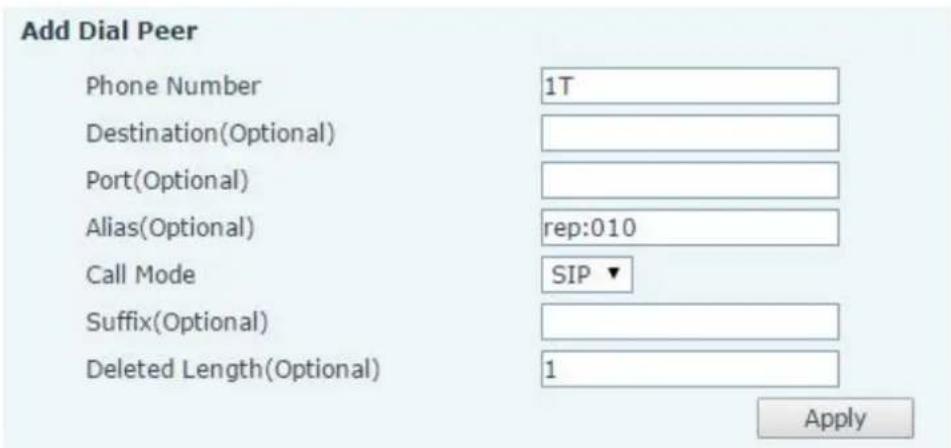
Figure 70 - Local Substitution Configuration
Example 3: Add Prefixes
If the dialed number starts with the fixed prefix number, the phone will send out your dialed phone number adding prefix number automatically.
For example, when users dial "9312", the device will send out "0079312".
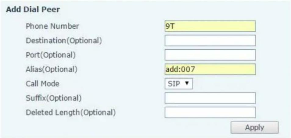
Figure 71 - Add Prefixes Configuration
Example 4: Add Suffixes
If the dialed number ends with the fixed suffix number, the phone will send out your dialed phone number adding suffix number automatically.
For example, when users dial "1383322", the device will send out "13833220088".

Figure 72 - Add Suffixes Configuration
Example 5: Deletion
If the dialed number ends with the fixed prefix number, the phone will send out your dialed phone number deleting prefix number automatically.
For example, when users dial "98322", the device will send out "8322".

Figure 73 - Deletion Configuration
8.14 LINES / Dial Plan

Figure 74 - Dial Plan Configuration
The device supports 8 dialing modes:
- Press # to Send - Dial the desired number, and press # to send it to the server.
- Dial Fixed Length – Configure the fixed length to dial out
- Send after seconds – Number will be sent to the server after the specified time.
- Press # to Do Blind Transfer - Press # after entering the target number for the transfer. The phone will transfer the current call to the third party.
- Blind Transfer on Onhook - Hang up after entering the target number for the transfer. The phone will transfer the current call to the third party.
- Attended Transfer on Onhook - Hang up after the third party answers. The phone will transfer the current call to the third party.
- Attended Transfer on Conference Onhook - Hang up during a 3-way conference call, the other two ways will make a call.
- Press DSS Key to Do Blind Transfer – When user is in the 'XFER' screen, user can fulfill Blind Transfer by pressing DSS Key.
8.15 LINES / Basic Settings
Configure basic settings for lines.
Table 4 - Basic Settings for Lines on Web
| Parameters | Description |
| SIP Settings | |
| Local SIP Port | Set the local SIP port used to send/receive SIP messages. |
| Registration Failure Retry Interva | Set the retry interval of SIP REGISTRATION when registra failed. |
| STUN Settings | |
| Server Address | Set the STUN server address |
| Server Port | Set the STUN server port, default is 3478 |
| Binding Period | Set the STUN binding period which can be used to keep NAT pinhole opened. |
| SIP Waiting Time | Set the timeout of STUN binding before sending SIP mess |
| TLS Certification File | Upload or delete the TLS certification file used for encrypte SIP transmission. |
8.16 PHONE / Features
Configure the phone features
Table 5 - Common Phone Feature Settings on Web
| Parameters | Description |
| DND Mode | Configure the Phone DND. If enable Phone DND, the phone reje any incoming call, the caller will automatically prompt hang up. |
| Ban Outgoing | If you select Ban Outgoing to enable it, and you cannot dial out number. |
| Enable Call Waiting | Enable this setting to allow user to take second incoming call du an established call. Default enabled. |
| Enable Call Waiting Tone | Turn off this feature, and you will not hear a ‘beep’ sound in tal mode when there is another incoming call |
| Auto Hand up Delay | Specify Auto handdown time, the phone will hang up and return idle automatically after Auto Hand down time at hands-free mode play dial tone Auto handdown time at handset mode |
| Enable Call Completion | Enable Call Completion by selecting it, If the dialed line is busy, server will inspect the dialed line status at intervals. If the dialed idle, the server will send notify message to inform the caller whe redial. |
| Hide DTMF | Configure the hide DTMF mode |
| Enable Pre-Dial | Disable this feature, user entering number will open audio channel automatically.Enable the feature, user enter the number without opening audio channel. |
| Enable Silent Mode | Enable Silent Mode by selecting it, the phone light will red blink remind that there is a missed call instead of playing ring tone. |
| Disable Mute for Ring | Disable Mute for Ring |
| Enable Intercom | When intercom is enabled, the device will accept the incoming ca request with a SIP header of Alert-Info instruction to automatically answer the call after specific delay. |
| Enable Intercom Mute | Enable mute mode during the intercom call |
| Enable Intercom Tone | If the incoming call is intercom call, the phone plays the intercom |
| Enable Intercom Barge | Enable Intercom Barge by selecting it, the phone auto answers t intercom call during a call. If the current call is intercom call, the will reject the second intercom call |
| Auto Answer By Headset | When this item is checked, the device will auto-answer phone ca headset if the auto-answer or intercom is enabled. |
| Ring From Headset | Enable Ring From Handset by selecting it, the phone plays ring from handset. |
| Emergency Call Number | Configure the Emergency Call Number. Despite the keyboard is locked, you can dial the emergency call number |
| Enable Password Dial | Enable Password Dial by selecting it, When number entered is beginning with the password prefix, the following N numbers after password prefix will be hidden as *, N stand for the value which enter in the Password Length field. For example: you set the password prefix is 3, enter the Password Length is 2, then you the number 34567, it will display 3**67 on the phone. |
| Password Dial Prefix | Configure the prefix of the password call number |
| Enable Phone DND | Enable Phone DND |
| DND Response Code | Set the SIP response code on call rejection on DND |
| Busy Response Code | Set the SIP response code on line busy |
| Reject Response Code | Set the SIP response code on call rejection |
| Encryption Number Length | Configure the Encryption Number length |
| Restrict Active URI Source IP | Set the device to accept Active URI command from specific IP address. |
| Push XML Server | Configure the Push XML Server, when phone receives request, it determine whether to display corresponding content on the phone which sent by the specified server or not. |
| Allow IP Call | If enabled, user can dial out with IP address |
| Enable Multi Line | Enable phone to make calls for 10 lines max, or disable for 2 li max. |
| Enable Default Line | If enabled, user can assign default SIP line for dialing out rather SIP1. |
| Enable Auto Switch Line | Enable phone to select an available SIP line as default automatic |
| Play Talking DTMF Tone | Play DTMF tone on the device when user pressed a phone digit during taking, default enabled. |
| Play Dialing DTMF Tone | Play DTMF tone on the device when user pressed a phone digit dialing, default enabled. |
| Caller ID Display Priority | Change caller ID display priority. The default priority is “Phonebox “SIP Display Name” > “SIP URI”. User may select one of the op to change the desired caller ID display priority. |
| Hotline Number | Set the Hot line Number |
| Hotline Delay | Set the Hot line Delay time. |
| Enable Silent Mode | Enable silent mode by selecting it, the phone incoming call indica will blink to remind that there is a incoming call instead of playir tone. |
| Disable Mute for Ring | Disable mute for ring. |
Action URL
URL for various actions performed by the phone. These actions are recorded and sent as xml files to the server. Sample format is http://InternalServer /FileName.xml
Restrict Outgoing Call
The user with Administrators privilege can set the rule to restrict some numbers from dialing out. This setting is device-wide and applies to every user of the device.
User can add restricted number by entering the number in the edit box and click "Add" button. To remove a number from the restriction list, select the number from the dropdown box and click "Delete" button to remove it.
8.17 PHONE / Audio
Change the audio settings.
Table 6 - Audio Settings on Web
| Parameters | Description |
| First Codec | The first preferential DSP codec:G.711A/U,G.722,G.723,G.729,G.726-32 |
| Second Codec | The second preferential DSP codec:G.711A/U,G.722,G.723,G.729,G.726-32 |
| Third Codec | The third preferential DSP codec: G.711A/U,G.722,G.723,G.729,G.726-32 |
| Fourth Codec | The forth preferential DSP codec: G.711A/U,G.722,G.723,G.729,G.726-32 |
| Fifth Codec | The fifth preferential DSP codec: G.711A/U,G.722,G.723,G.729,G.726-32 |
| Sixth Codec | The sixth preferential DSP codec: G.711A/U,G.722,G.723,G.729,G.726-32 |
| Onhook Time | Configure the least reflection time of Hand down, the default is 200ms. |
| Tone Standard | Set the country standard of call progress tones, including dial busy tone, ring-back tone, etc. |
| Handset Volume | Set the Handset volume, the value must be 1~9 |
| Default Ring Type | Set the default ring type. If the caller ID of an incoming call v configured with specific ring type, the default ring will be used. |
| Speakerphone Volume | Set the speakerphone volume, the value must be 1~9 |
| Headset Ring Volume | Set the ring volume in the headset, the value must be 0~9 |
| Headset Volume | Set the Headset volume, the value must be 1~9 |
| Speakerphone Ring Volume | Set the ring volume in the speakerphone, the value must be 0~9 |
| Headset Volume Offset | This is to adjust the base volume of the headset. Please note set the volume at the maximum level it may create noise and decrease the echo canceller. |
| Headset Mic Offset | This is to adjust the base volume of the headset Mic. |
| G.729AB Payload Length | Set G729 Payload Length. |
| G.723.1 Bit Rate | 5.3kb/s or 6.3kb/s is available |
| G.722 Timestamps | 160/20ms or 320/20ms is available |
| DTMF Payload Type | Enter the DTMF payload type, the value must be 96~127. |
| Enable VAD | Enable Voice Activity Detection. When enabled, the device will suppress the audio transmission with artificial comfort noise sig to save the bandwidth. |
| Enable MWI Tone | The phone will play MWI tone when a new MWI Comes |
8.18 PHONE / MCAST
This feature allows user to make some kind of broadcast call to people who are in multicast group. User can configure a multicast DSS Key on the phone, which allows user to send a Real Time Transport Protocol (R1) stream to the pre-configured multicast address(es) without involving SIP signaling. You can also configure the phone to receive an RTP stream from pre-configured multicast listening address(es) without involving SIP signaling. You can specify up to 10 multicast listening addresses.
Table 7 - MCAST Parameters on Web
| Parameters | Description |
| Normal Call Priority | Define the priority of the active call, 1 is the highest priority, 10 is th |
| Enable Page Priority | The voice call in progress shall take precedence over all incoming pa calls. |
| Name | Listened multicast server name |
| Host:port | Listened multicast server's multicast IP address and port. |
8.19 PHONE / Time/Date
User can configure the device time settings in this page.
Table 8 - Time/Date Setting Parameters on Web
| Parameters | Description |
| Network Time Server Settings | |
| Time Synchronized via SNTP | Enable time-sync through SNTP protocol |
| Time Synchronized via DHCP | Enable time-sync through DHCP protocol |
| Primary Time Server | Set primary time server address |
| Secondary Time Server | Set secondary time server address, when primary server is reachable, the device will try to connect to secondary time server to get time synchronization. |
| Timezone | Select the time zone |
| Resync Period | Time of re-synchronization with time server |
| 12-Hour Clock | Set the time display in 12-hour mode |
| Date Format | Select the time/date display format |
| Daylight Saving Time Settings | |
| Location | Select the user's time zone specific area |
| DST Set Type | Select automatic DST according to the preset rules of DST the manually input rules |
| Offset | The DST offset time |
| Month Start | The DST start month |
| Week Start | The DST start week |
| Weekday Start | The DST start weekday |
| Hour Start | The DST start hour |
| Minute Start | The DST start minute |
| Month End | The DST end month |
| Week End | The DST end week |
| Weekday End | The DST end weekday |
| Hour End | The DST end hour |
| Manual Time Settings | Set time manually |
8.20 PHONE / Advanced
User can configure the advanced configuration settings in this page.
- Screen Configuration.
■ Enable Energysaving
■ Backlight Time - LCD Menu Password Settings.
The password is 123 by default.
● Keyboard Lock Settings. - Configure Greeting Words
The greeting message will display on the top left corner of the LCD when the device is idle, which is limited 12 characters. The default chars are 'C401 IPPHONE'.
8.21 PHONEBOOK / Contacts
User can add, delete, or edit contacts in the phonebook in this page. User can browse the phonebook and sorting it by name, phones, or filter them out by group.
To add a new contact, user should enter contact's information and press "Add" button to add it.
To edit a contact, click on the checkbox in front of the contact, the contact information will be copied to the contact edit boxes, press "Modify" button after finished editing.
To delete one or multiple contacts, check on the checkbox in front of the contacts wished to be deleted and click the "Delete" button, or click the "Clear" button with selecting any contacts to clear the phonebook.
User can also add multiple contacts into a group by selecting the group in the dropdown options in front of "Add to Group" button at the bottom of the contact list, selecting contacts with checkbox and click "Add to Group" to add selected contacts into the group.
8.22 PHONEBOOK / Cloud Phonebook
Cloud Phonebook
User may configure up to 8 cloud phonebooks. Each cloud phonebook must be configured with an URL where an XML phonebook is stored. The URL may be based on HTTP/HTTPS or FTP protocol with or without authentication. If authentication is required, user must configure the username and password.
To configure a cloud phonebook, the following information should be entered,
Phonebook name (must)
Phonebook URL (must)
Access username (optional)
Access password (optional)
LDAP Settings
The cloud phonebook allows user to retrieve contact list from a LDAP Server through LDAP protocols.
User must configure the LDAP Server information and Search Base to be able to use it on the device. If the LDAP server requests an authentication, user should also provide username and password.
To configure a LDAP phonebook, the following information should be entered,
Display Title (must)
LDAP Server Address (must)
LDAP Server Port (must)
Search Base (must)
Access username (optional)
Access password (optional)
8.23 PHONEBOOK / Blacklist
By adding a number into the blacklist, user will no longer receive phone call from that number and it will be rejected automatically by the device until user delete it from the blacklist.
User can add specific number to be blocked, or a prefix where any numbers matched the prefix will all be blocked.
8.24 PHONEBOOK / Advanced
User may export current phonebook in xml, csv, or vcf format file and save it locally on a computer.
User can also import contacts into phonebook from an xml, csv, or vcf file.
NOTICE: If user repeatedly imports a same phonebook, it will not create duplicated contacts in user's phonebook.
User can add new group in this page or delete an existing one. Deleting a contact group will not delete the contacts in that group.
8.25 CALL LOGS
User can browse complete call logs in this page, order the call logs by time, caller ID, contact name, duration or line, and can also filter the call logs by the call log types, in, out, missed, or all.
User can save a call log into his/her phonebook or add it to the blacklist.
User can also make web call by click on the number of a call log.
8.26 FUNCTION KEY / Function Key
The device provides 28 user-define DSS Keys at most. User may configure/customize each DSS key in this webpage.
Table 9 - DSS Key Setting Parameters on Web
| Parameters | Description |
| Memory Key | BLF(NEW CALL/BXFE /AXFER): It is used to prompt user the state subscribe extension, and it can also pick up the subscribed number which help user monitor the state of subscribe extension (idle, ring call). There are 3 types for one-touch BLF transfer method.p.s. User should enter the pick-up number for specific BLF key to the pick-up operation.Presence: Compared to BLF, the Presence is also able to view with the user is online.Note: You cannot subscribe the same number for BLF and Present the same timeSpeed Dial: You can call the number directly which you set. This feature is convenient for you to dial the number which you frequently dialed.Intercom: This feature allows the operator or the secretary to continue the phone quickly; it is widely used in office environments.MWI: You can set the speed dial key for the voice messages.Call Park: You can retrieve the held call by using the call park or Call forward: You can transfer the call to the set number. |
| Line | It can be configured as a Line Key. User is able to make a call pressing Line Key. |
| Key Event | User can select a key event as a shortcut to trigger.For example: MWI / DND / Release / Headset / Hold / Conferenc |
| DTMF | It allows user to dial or edit dial number easily. |
| URL | Open the specific URL directly. |
| Multicast | Configure the multicast address and audio codec. User presses the list to initiate the multicast. |
| BLF List Key | You can view the subscription status of the subscribed numbers. |
| LDAP | You can store the phonebook via the LDAP function |
8.27 FUNCTION KEY / Softkey
User can configure different functions in different screens for each softkey.
SoftKey Settings
Softkey Mode
Screen

Unselected Softkeys
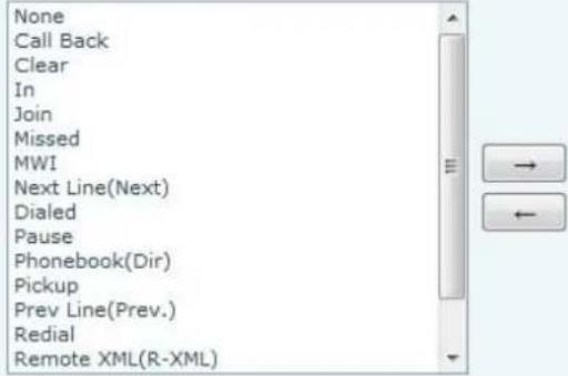
Selected Softkeys


Figure 75 - Softkey Configuration
9. Advanced Features
9.1 VPN
Virtual Private Network (VPN) is a technology to allow device to create a tunneling connection to a server and becomes part of the server's network. The network transmission of the device may be routed through the VPN server.
For some users, especially enterprise users, a VPN connection might be required to be established before activate a line registration. The device supports two VPN modes, Layer 2 Transportation Protocol (L2TP) and OpenVPN. The VPN connection must be configured and started (or stopped) from the device web portal.
9.1.1 L2TP
NOTICE: The device only supports non-encrypted basic authentication and non-encrypted data tunneling.
For users who need data encryption, please use OpenVPN instead.
To establish a L2TP connection, users should log in to the device web portal, open page [Network] -> [VPN]. In VPN Mode, check the "Enable VPN" option and select "L2TP", then fill in the L2TP server address, Authentication Username, and Authentication Password in the L2TP section. Press "Apply" then the device will try to connect to the L2TP server.
When the VPN connection established, the VPN IP Address should be displayed in the VPN status. There may be some delay of the connection establishment. User may need to refresh the page to update the status. Once the VPN is configured, the device will try to connect to the VPN automatically when the device boots every time until user disable it. Sometimes, if the VPN connection does not establish immediately, user may try to reboot the device and check if VPN connection established after reboot.
9.1.2 OpenVPN
To establish an OpenVPN connection, user should get the following authentication and configuration files from the OpenVPN hosting provider and name them as the following,
OpenVPN Configuration file: client.ovpn
CA Root Certification: ca.crt
Client Certification: client.crt
Client Key: client.key
User then upload these files to the device in the web page [Network] -> [VPN], Section OpenVPN Files. The user should check "Enable VPN" and select "OpenVPN" in VPN Mode and click "Apply" to enable OpenVPN connection.
Same as L2TP connection, the connection will be established every time when system rebooted until user isable it manually.
10. Trouble Shooting
When the device does not work properly, users may try the following methods to recover the device or gather relative information and send an issue report to support.
10.1 Get Device System Information
Users may get the device system information by pressing [Settings] -> [Status]. The following basic information will be provided:
Mode
IP
Software Version
More...
User can select [More] item to get more information in detail.
10.2 Upgrade to the latest software
Manufacturer will keep publishing software update to fix bugs and improve device features. The device will check for new software release on manufacturer cloud server automatically and periodically.
10.3 Reboot Device
Users may reboot the device from soft-menu, [Menu] -> [Reboot System], and confirm the action by [Yes]. O simply remove the power supply and restore it again.
10.4 Reset Device to Factory Default
Reset Device to Factory Default will erase all user's configuration, preference, database and profiles on the device and restore the device back to the state as factory default.
To perform a factory default reset, user should [Menu] -> [Settings] -> [Advanced settings], and then input the password to enter the interface. Then choose [Reset to Default] and press [Enter], and confirm the action by [Yes]. The device will be rebooted into a clean factory default state.
10.5 Network Packets Capture
Sometimes it is helpful to dump the network packets of the device for issue identification. To get the packets dump of the device, user needs to log in the device web portal, open page [System] -> [Tools] and click [S in "Network Packets Capture" section. A pop-up message will be prompt to ask user to save the capture file. User then should perform relevant operations such as activate/deactivate line or making phone calls and click [STOP] button in the web page when operation finished. The network packets of the device during the period have been dumped to the saved file. User may examine the packets with a packet analyzer or send it to support.
10.6 Entering Post Mode and Recover System Image
WARNING: PLEASE AVOID UPDATING SYSTEM IMAGE FROM POST MODE UNLESS THE SYSTEM IMAGE IS DAMAGED.
If the device could not boot up and entered into POST MODE, it is usually because of system image damaged due to power failure during software upgrade. When this occurs, users may follow below steps to restore the system image.
Step 1. Download the latest device software.
Step 2. Setup a FTP server on a PC and put the downloaded software in the FTP repository. (Windows users can download free FTP server software such as WFTPD32 or 3CDaemon)
Step 3. Configure the PC with fixed IP address as 192.168.10.10
Step 4. Connect device network with the PC.
Step 5. Telnet from PC to device: >telnet 192.168.10.1
Step 6. When telnet connection established, it will run POST maintenance tools, please select '2' – FTP update image, and fill in required information to start the image update.
Step 7. Once update finished, please select '4' to reboot the device.
10.7 Common Trouble Cases
Table 10 - Trouble Cases
| Trouble Case | Solution |
| Device could not boot up | 1. The device is powered by external power supply via power adapter PoE switch. Please use standard power adapter provided or PoE s met with the specification requirements and check if device is well connected to power source.2. If you saw “POST MODE” on the device screen, the device system image has been damaged. Please refer to the instructions in “10.6 Entering Post Mode and Recover System Image” to restore the system image. |
| Device could not register to a service provider | 1. Please check if device is well connected to the network. The netwo Ethernet cable should be connected to the [Network] port NOT the [PC] port. If the cable is not well connected to the network ic [WAN disconnected] will be flashing in the middle of the scree2. Please check if the device has an IP address. Check the system information, if the IP displays “Negotiating...”, the device does not I an IP address. Please check if the network configurations is correct3. If network connection is fine, please check again your line configurations. If all configurations are correct, please kindly contactyour service provider to get support, or follow the instructions in “1 Network Packet Capture” to get the network packet capture of registration process and send it to support to analyze the issue. |
| No Audio or Poor Audi in Handset | Please check if Handset is connected to the correct Handset ( ) po NOT Headphone ( ) port.The network bandwidth and delay may be not suitable for audio ca the moment. |
| Poor Audio or Low Volume in Headphone | There are two Headphone wire sequence in the market. Please use Headphone provided, or consult the wire sequence if you wish to third party headphone.The network bandwidth and delay may be not suitable for audio ca the moment. |
| Audio is chopping at far-end in Hands-free speaker mode | This is usually due to loud volume feedback from speaker to micropho Please lower down the speaker volume a little bit, the chopping will be |
Appendix I - Icon Illustration
Table 11 - Keypad Icons
| Redial | |
| Handsfree (HF) speaker | |
| Phone lock=long-pressed key(#) | |
| Mute microphone (during Call) | |
| Volume up | |
| Volume down |
Table 12 - Status Prompt and Notification Icons
 | Call out |
 | Call in |
 | Call hold |
 | Network disconnected |
 | Keypad locked |
 | Missed calls |
 | SMS |
 | New voice message waiting |
 | Do-not-disturb activated on phone |
 | Auto-answering activated |
 | Call forward activated |
 | Handsfree (HF) mode |
 | Headphone (HP) mode |
 | Handset (HS) mode |
 | Microphone muted |
 | Mixed type input |
 | Lower case input |
 | Upper case input |
 | Numeric input |
Appendix II - Text Input from Keypad
Table 13 - Look-up Table of Characters
| Mode Icon | Text Mode | Key Button | Characters Of Each Press |
| 123 | Numeric | 1 | 1 |
| 2 | 2 | ||
| 3 | 3 | ||
| 4 | 4 | ||
| 5 | 5 | ||
| 6 | 6 | ||
| 7 | 7 | ||
| 8 | 8 | ||
| 9 | 9 | ||
| 0 | 0 | ||
| * | *#(space)@, :/?<>[]%! &~+- | ||
| # | # | ||
| abc | Lower Case Alphabets | 1 | + - * % / | @ ! : |
| 2 | a b c | ||
| 3 | d e f | ||
| 4 | g h i | ||
| 5 | j k l | ||
| 6 | m n o | ||
| 7 | p q r s | ||
| 8 | t u v | ||
| 9 | w x y z | ||
| 0 | 0 | ||
| * | *#(space)@, :/?<>[]%! &~+- | ||
| # | # | ||
| ABC | Upper Case Alphabets | + - * % / | @ ! : | |
| A B C | |||
| D E F | |||
| G H I | |||
| J K L | |||
| M N O | |||
| P Q R S | |||
| T U V | |||
| WZYX | |||
| (space) | |||
| *#(space)@,:/?<>[]%! &~+- | |||
| # | |||
| 2aB | Mixed type input | 1 + - * % / | @ ! : | |
| 2 a b c A B C | |||
| 3 d e f D E F | |||
| 4 g h I G H I | |||
| 5 j k l J K L | |||
| 6 m n o M N O | |||
| 7 p q r s P Q R S | |||
| 8 t u v T U V | |||
| 9 w z y x W Z Y X | |||
| (space) | |||
| *#(space)@,:/?<>[]%! &~+- | |||
| # |
Appendix III - LED Definition
Table 14 - DSS KEY LED State
| Type | LED Light | State |
| Line Key | Off | Line inactive |
| Green On | Line ready (registered) | |
| Green Blinking | Dialing / ringing / call holding | |
| BLF | Green On | Subscribed number is idle. |
| Red On | Subscribed number is busy. | |
| Red Blinking | Subscribed number is dialing. | |
| Off | Subscribed number is unavailable | |
| Headset Key | Green On | Enable headset |
| Off | Disable headset | |
| MWI | Green On | New voice message waiting |
| Off | No new voice message |



- OpenVox Communication Co., Ltd
- C401 User Manual\_V1.0
- OpenVox
- OpenVox Communication Co.,Ltd
- Content
- Revision History......1
- Safety Instruction....1
- Overview....2
- Installation....3
- Introduction to the Phone User Interface....6
- Setting Up.... 10
- Using the Phone....15
- Phone Settings....32
- Web Portal....35
- Advanced Features....54
- Trouble Shooting....55
- Safety Instruction
- Overview
- Installation
- Use PoE or external Power Adapter
- Desktop and Wall-mount Installation
- Introduction to the Phone User Interface
- Keypad
- Using Handset / Hands-free Speaker / Headphone
- - Using Handset
- ● Using Hands-free Speaker
- - Using Headphone
- ● Using Line Keys(Defined by DSS Key)
- Screen User Interface
- Web Portal
- Setting Up
- Network Configuration
- Line Configurations
- Using the Phone
- Making Phone Calls
- - Default Line
- - Dialing Methods
- - Dialing Number then Opening Audio
- - Opening Audio then Dialing the Number
- - Cancel Call
- - Answering Incoming Call
- - Talking
- - Call Holding /Resuming
- - Call Ended
- Make / Receive Second Call
- - Second Incoming Call
- - Second Outgoing Call
- - Switching between Two Calls
- - Ending One Call
- Join / Split Two Calls (3-way Local Conference)
- Call Transfer
- - Attended Transfer
- ● Unattended / Blind Transfer
- Using Phonebook
- Add / Edit / Delete Contact
- Add / Edit / Delete Group
- Browse and Add / Remove Contacts in Group
- Using Cloud Phonebook
- Open Cloud Phonebook
- Call Logs
- Voice Message
- Do-Not-Disturb
- Auto-Answering
- Call Forward
- DSS LCD Configuration
- Phone Settings
- Adjust Audio Volume
- Set Ring Tone Volume and Type
- Adjust LCD Energy Saving
- Set Device Time/Date
- Set Device Language
- Reboot the Device
- Reset to Factory Default
- Web Portal
- Web Portal Authentication
- Web Call
- SYSTEM / Information
- SYSTEM / Account
- SYSTEM / Configurations
- SYSTEM / Upgrade
- SYSTEM / Auto Provision
- SYSTEM / Tools
- NETWORK / Basic
- NETWORK / Advanced
- NETWORK / VPN
- LINES / SIP
- LINES / Dial Peer
- Examples of different alias application
- Example 1: Global Substitution
- Example 2: Local Substitution
- Example 3: Add Prefixes
- Example 4: Add Suffixes
- Example 5: Deletion
- LINES / Dial Plan
- LINES / Basic Settings
- PHONE / Features
- Action URL
- Restrict Outgoing Call
- PHONE / Audio
- PHONE / MCAST
- PHONE / Time/Date
- PHONE / Advanced
- PHONEBOOK / Contacts
- PHONEBOOK / Cloud Phonebook
- Cloud Phonebook
- LDAP Settings
- PHONEBOOK / Blacklist
- PHONEBOOK / Advanced
- CALL LOGS
- FUNCTION KEY / Function Key
- FUNCTION KEY / Softkey
- SoftKey Settings
- Advanced Features
- VPN
- L2TP
- OpenVPN
- Trouble Shooting
- Get Device System Information
- Upgrade to the latest software
- Reboot Device
- Reset Device to Factory Default
- Network Packets Capture
- Entering Post Mode and Recover System Image
- Common Trouble Cases
- Appendix I - Icon Illustration
- Appendix II - Text Input from Keypad
- Appendix III - LED Definition
Brand : OpenVox
Model : C401
Category : Telephone