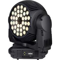
MAC 401 Dual CT Zoom - Projector MARTIN - Free user manual and instructions
Find the device manual for free MAC 401 Dual CT Zoom MARTIN in PDF.


| Product Type | LED Moving Head Profile Projector |
| Model | MAC 401 Dual CT Zoom |
| Brand | Martin |
| Light Source | LED Engine, 400W |
| Color Temperature Range | 2700K – 6500K (Dual CT) |
| Zoom Range | 5° – 45° |
| Pan Movement | 540° (Continuous rotation optional) |
| Tilt Movement | 270° |
| Control Protocol | DMX512, RDM, Art-Net |
| Power Consumption | 600W maximum |
| Power Supply | 100-240V AC, 50/60Hz |
| Dimensions (L x W x H) | 400 x 300 x 600 mm |
| Weight | 22 kg |
| Housing Material | Aluminum and composite materials |
| IP Rating | IP20 (Indoor use only) |
| Cooling System | Fan-cooled with temperature monitoring |
| Noise Level | < 35 dB(A) in silent mode |
| Lamp Life | 50,000 hours (L70) |
| Firmware Update | Via USB or DMX (RDM) |
Frequently Asked Questions - MAC 401 Dual CT Zoom MARTIN
User questions about MAC 401 Dual CT Zoom MARTIN
0 question about this device. Answer the ones you know or ask your own.
Ask a new question about this device
Download the instructions for your Projector in PDF format for free! Find your manual MAC 401 Dual CT Zoom - MARTIN and take your electronic device back in hand. On this page are published all the documents necessary for the use of your device. MAC 401 Dual CT Zoom by MARTIN.
USER MANUAL MAC 401 Dual CT Zoom MARTIN
natural_image
Two black industrial lighting units with blue and white LED array lights, displayed side by side (no text or symbols visible)Dimensions
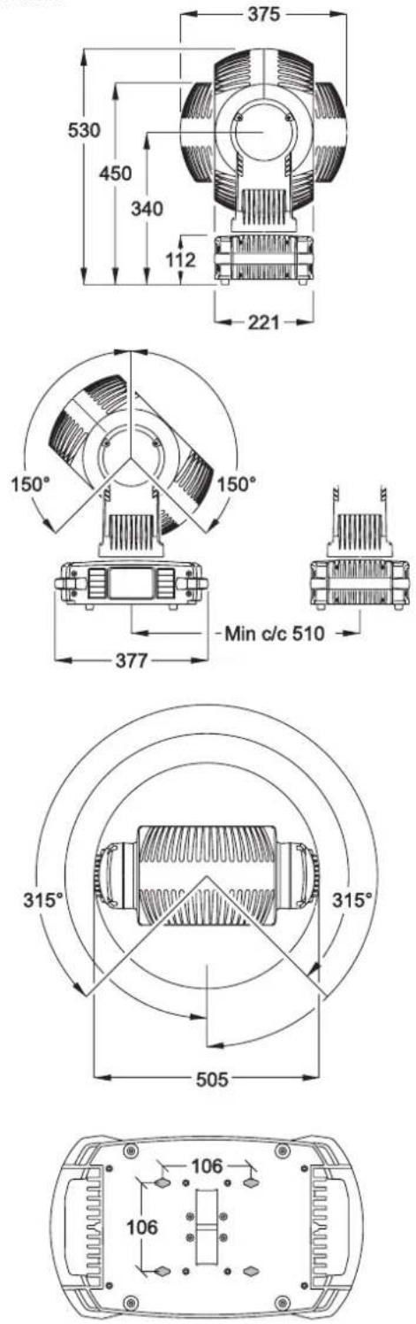
All dimensions are in millimeters
©2009-20010 Martin Professional A/S. Information subject to change without notice. Martin Professional A/S and all affiliated companies disclaim liability for any injury, damage, direct or indirect loss, consequential or economic loss or any other loss occasioned by the use of, inability to use or reliance on the information contained in this manual. The Martin logo, the Martin name and all other trademarks in this document pertaining to services or products by Martin Professional A/S or its affiliates and subsidiaries are trademarks owned or licensed by Martin Professional A/S or its affiliates or subsidiaries. The use of certain patents in Martin™ MAC 401™ products is licensed by Color Kinetics, Inc. (see details printed on product).
P/N 35000229, Rev. F
Safety Information

WARNING!
Read the safety precautions in this section before installing, powering, operating or servicing this product.
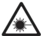
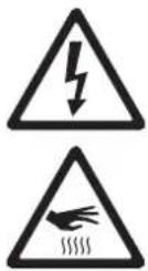
The following symbols are used to identify important safety information on the product and in this manual:

DANGER!
Safety hazard.
Risk of severe
injury or death.

DANGER!
Hazardous
voltage. Risk of
lethal or severe
electric shock.

WARNING!
Fire hazard.
WARNING!
LED light
emission. Risk of
eye injury.

WARNING!
Burn hazard. Hot
surface. Do not
touch.

WARNING!
Wear protective
eyewear.

WARNING! Refer to user manual.

Warning! Class 3B LED product. Do not look into the beam at a distance of less than 1 meter (3 feet 4 inches) from the front surface of the product. Do not view the light output with optical instruments or any device that may concentrate the beam.

This product is for professional use only. It is not for household use.
This product presents risks of severe injury or death due to fire and burn hazards, electric shock and falls.

Read this manual before installing, powering or servicing the fixture, follow the safety precautions listed below and observe all warnings in this manual and printed on the fixture. If you have questions about how to operate the fixture safely, please contact your Martin supplier or call the Martin 24-hour service hotline on +45 8740 0000, or in the USA on 1-888-tech-180.

PROTECTION FROM ELECTRIC SHOCK
- Disconnect the fixture from AC power before removing or installing any cover or part – including fuses – and when not in use.
• Always ground (earth) the fixture electrically. - Use only a source of AC power that complies with local building and electrical codes and has both overload and ground-fault (earth-fault) protection.
- Before using the fixture, check that all power distribution equipment and cables are in perfect condition and rated for the current requirements of all connected devices.
- Isolate the fixture from power immediately if any power connector, power cable, seal, cover or other component is damaged, defective, deformed, wet or showing signs of overheating. Do not reapply power until repairs have been completed.
- Do not expose the fixture to rain or moisture.
- Refer any service operation not described in this manual to a qualified technician.

PROTECTION FROM BURNS AND FIRE
- Do not operate the fixture if the ambient temperature (Ta) exceeds 40^ ( 104^ ).
- The exterior of the fixture becomes hot during use. Avoid contact by persons and materials. Allow the fixture to cool for at least 10 minutes before handling.
- Keep all combustible materials (e.g. fabric, wood, paper) at least 200 mm (8 in.) away from the head.
- Keep flammable materials well away from the fixture.
- Ensure that there is free and unobstructed airflow around the fixture.
- Do not illuminate surfaces within 200 mm (8 in.) of the fixture.
- Do not attempt to bypass thermostatic switches or fuses. Replace defective fuses with ones of the specified type and rating.
- Do not modify the fixture in any way not described in this manual
• Install only genuine Martin parts.

PROTECTION FROM INJURY
- Do not look at LEDs from a distance of less than 1 meter (3 feet 4 inches) from the front surface of the fixture without protective eyewear such as shade 4-5 welding goggles. At less than this distance, the LED emission can cause eye injury or irritation. At distances of 1 meter (3 feet 4 inches) and above, light output is harmless to the naked eye provided that the eye's natural aversion response is not overcome.
- Do not look at LEDs with magnifiers, telescopes, binoculars or similar optical instruments that may concentrate the light output.
- Ensure that persons are not looking at the LEDs from within 1 meter (3 feet 4 inches) when the product lights up suddenly. This can happen when power is applied, when the product receives a DMX signal or when service menu items are selected in the SERV menu.
- To minimize the risk of eye irritation or injury, set the zoom to wide angle and disconnect the fixture from power at all times when the fixture is not in use, and provide well-lit conditions to reduce the pupil diameter of anyone working on or near the fixture.
- Install as described in this manual a secondary attachment such as a safety cable that is approved by an official body such as TÜV as a safety attachment for the weight of all the fixtures it secures. The safety cable must comply with EN 60598-2-17 Section 17.6.6 and be capable of bearing a static suspended load ten times the weight of the fixture.
- If suspending from a rigging structure, attach the fixture with two evenly spaced clamps. Do not use only one clamp.
- Ensure that any supporting structure and/or hardware used can hold at least 10 times the weight of all the devices they support.
- Allow enough clearance around the head to ensure that it cannot collide with an object or another fixture when it moves.
- Check that all external covers and rigging hardware are securely fastened.
- Block access below the work area and work from a stable platform whenever installing, servicing or moving the fixture.
- Do not operate the fixture with missing or damaged covers, shields or any optical component.


Contents
Dimensions 2
Safety Information....3
Introduction 6
Unpacking 6
Using for the first time 6
Connections panel 7
AC power 8
Power voltage 8
Power cable and plugs 8
Data link 10
Tips for reliable DMX data transmission 10
Connecting the DMX data link....10
Physical installation 11
Placing the fixture on a flat surface 11
Mounting the fixture on a truss 11
Setup....12
Control panel and menu navigation....12
Restoring factory default settings 13
Pixel grouping 13
DMX setup....13
Tailoring performance 16
Effects....18
MAC 401 - all models ..... 18
MAC 401 Dual / RGB Zoom LED module 18
MAC 401 CT Zoom / CT Zoom LED module....19
Service and maintenance....20
Cleaning....20
Removing and installing head modules....21
Control menu service utilities....22
Fixture readouts....23
Lubrication 23
Fuse replacement 23
Diagnostic feedback 24
DMX protocols 25
DMX protocol, RGB Zoom module 25
DMX protocol, CT Zoom module....31
LEE colors and RGB equivalents 35
Onboard control menus 36
Single head module operation....36
Dual head module operation 38
Adjustment submenu....42
Troubleshooting 43
MAC 401 Specifications 44
Introduction
Thank you for selecting the MAC 401 ^™ , an intelligent LED-based moving head washlight fixture from Martin Professional ^™ that is available in two models:
- The MAC 401 Dual™, with an RGB Zoom LED module fitted as standard
- The MAC 401 CT Zoom™, with a CT (Color Temperature) Zoom LED module fitted as standard.
The MAC 401 features:
- A twin-face head that can operate with one or two plug-and-play LED modules
- Various RGB (red, green, blue), HSV (hue, saturation, value), electronic 'color wheel' and CTC (color temperature control) control options depending on LED module(s) fitted and control mode selected
- DMX control
- Onboard control panel with LED display
- Two ranges of pre-programmed superimposable dynamic effects
- Four pixel grouping options
- Smooth electronic dimming
• Electronic strobe with pulse effects
- Motorized zoom providing beam angles from 20^ - 50^ , as well as 16^ Hypermode effect
- 630^ pan and 300^ tilt ranges
For the latest firmware updates, documentation, and other information about this and all Martin Professional products, please visit the Martin website at http://www.martin.com
Comments or suggestions regarding this document may be e-mailed to service@martin.dk or posted to: Technical Documentation, Martin Professional A/S, Olof Palmes Allé 18, DK-8200 Aarhus N, Denmark

Warning! Read "Safety Information" on page 3 before installing, powering, operating or servicing the MAC 401 ^TM .
Unpacking
The following items are included with the MAC 401:
- One LED head module (installed): RGB Zoom module in MAC 401 Dual, CTC Zoom module in MAC 401 CT Zoom
- Two clamp attachment brackets with quarter-turn fasteners
- This user manual
- Neutrik PowerCon input connector
Using for the first time
Before applying power to the fixture:
- Check the Martin Professional website at www.martin.com for the most recent user documentation and technical information about the MAC 401. Martin user manual revisions are identified by the letter at the bottom of page 2.
- Carefully review "Safety Information" on page 3.
- Check that the fixture's power voltage and frequency ranges match the local AC mains power source. See "Power voltage" on page 8.
- Prepare the cabling and connectors for running the fixture off AC power as described in “Power cable and plugs” on page 8.
Connections panel

A - AC mains power input (Neutrik PowerCon)
B – Fuseholder, mains fuse 1
C - Fuseholder, mains fuse 2
D – Ethernet 1 (RJ-45, for future use)
E – Ethernet 2 (RJ-45, for future use)
F - DMX in (5-pin XLR)
G - DMX out (5-pin XLR)
Figure 1: Connections panel overview
AC power

Warning! Read "Safety Information" starting on page 3 before connecting the MAC 401 to AC mains power.

For protection from electric shock, the MAC 401 must be grounded (earthed). The AC power distribution circuit must be equipped with a fuse or circuit breaker and ground-fault (earth-fault) protection.
The MAC 401 does not have a power on/off switch. To shut down power in an emergency, disconnect the fixture's power input connector.
Important! Do not use an external dimming system to supply power to the MAC 401, as this may cause damage to the fixture that is not covered by the product warranty.
The MAC 401 can be hard-wired to a building electrical installation if you want to install it permanently. If you do this, provide a means of shutting down power near the fixture. Alternatively a power cable (not supplied) with a power plug suitable for local power output sockets can be used to supply the fixture with AC mains power.
Power voltage

Warning! Check that the voltage range specified on the fixture's serial number label matches the local AC mains power voltage before applying power to the fixture.
MAC 401 fixtures are factory-configured to accept AC mains power at 100-240 V nominal, 50/60 Hz.
Do not apply AC mains power to the fixture at any other voltage than that specified on the fixture's serial number label.
Power cable and plugs
The fixture must be connected to AC power using three-conductor cable that is rated 20 A minimum (12 AWG or 2.5 mm ^2 ), with a diameter of 5 - 15 mm (0.2 - 0.6 in.). The cable jacket must be SJT type or better and heat-resistant to 90°C (194°F) minimum. A power cable is not supplied with the product.
The MAC 401 is supplied with a male Neutrik PowerCon NAC3FCA locking 3-pole input connector that can be attached to the end of the power cable. Only use this connector to disconnect the fixture from power in an emergency – frequent use can cause damage to the connector or socket due to arcing across the terminals.
The power cable can either be permanently connected to a building's electrical installation circuits (in this case an external power switch must be installed close to the fixture) or fitted with a power plug that is suitable for the local AC mains power outlets.
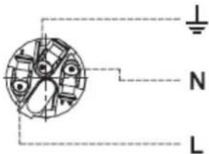
If you decide to install a power plug on the fixture's power cable, install a grounding-type (earthed) plug that is correctly rated for the current and power requirements of the fixture. Follow the plug manufacturer's instructions. Table 1 shows standard wire color-coding schemes and some possible pin identification schemes; if pins are not clearly identified, or if you have any doubts about proper installation, consult a qualified electrician.
| Wire Color (EU) Wire Color (US) Conductor Symbol Screw (US) | ||||
| brown black live L yellow or brass | ||||
| blue white neutral | N | silver | ||
| yellow/green | green | ground (earth) | ⊕ or ⊥ | green |
Table 1: Wire color-coding and power connections
Attaching a cable to the male input connector

natural_image
Technical line drawings of mechanical components (no text or symbols)Chuck BushingHousing Insert
To attach a power cable to the supplied input connector:
- Slide the bushing over the cable.
- Slide the white chuck over cables with a diameter (D _a ) of 5 - 10 mm (0.2 - 0.4 in.), or the black chuck over cables with a diameter of 10 - 15 mm (0.4 - 0.6 in.).
- Prepare the end of the cable by stripping 20 mm (0.8 in.) of the cable's outer jacket.
- Strip 8 mm (1/3 in.) from the end of each of the wires.
- Insert each of the wire ends into the appropriate terminal (see Table 1 above) and fasten the clamping device using a small flathead screw driver.
- Push and insert the chuck into the housing (note that there is a raised key on the chuck to ensure that it is oriented correctly).
- Fasten the bushing, using a wrench, to a torque of 2.5 Nm (1.8 lb-ft).
![20.00 mm [0.787°] 8.00 mm [0.315°] D₀](/content/2026/06/1369876/images/499c0f59bbf93be572b4fb157311c0eb3d43a39ed5dc6d59067ea5aec9120ca3.jpg)
Cable end
Terminals
Illustrations on this page used by kind permission of Neutrik AG.
Data link
A data link is required in order to control a MAC 401 via DMX.
The MAC 401 has 5-pin locking XLR connectors for DMX data input and output. The pin-out on XLR connectors is pin 1 = shield, pin 2 = cold (-), and pin 3 = hot (+).
Pins 4 and 5 in the 5-pin XLR connectors are not used in the MAC 401 but they are connected from the DMX input to the DMX output connector to allow any data that may be present on pins 4 and 5 to pass through the fixture.
Sockets are wired in parallel: both inputs connect to both outputs.
Two RJ-45 connectors are also provided, making the MAC 401 ready for future data communication options over an Ethernet link. If you wish to use these options when available, ensure that the latest available firmware is installed in the fixture.
Tips for reliable DMX data transmission
- Use shielded twisted-pair cable designed for RS-485 devices: standard microphone cable cannot transmit control data reliably over long runs. 24 AWG cable is suitable for runs up to 300 meters (1000 ft). Heavier gauge cable and/or an amplifier is recommended for longer runs.
- To split the link into branches, use a splitter such as the Martin™ RS-485 Opto-Splitter™ 4-channel optically isolated splitter/amplifier.
- Do not overload the link. Up to 32 devices may be connected on a serial link.
- Terminate the link by installing a termination plug in the output socket of the last fixture. The termination plug, which is a male XLR plug with a 120 Ohm, 0.25 Watt resistor soldered between pins 2 and 3, "soaks up" the control signal so it does not reflect and cause interference. If a splitter is used, terminate each branch of the link.
Connecting the DMX data link
- Connect the DMX data output from the controller to the MAC 401's 5-pin male XLR input socket.
- Continue connecting fixtures, DMX output to DMX input, in one single chain.
- Use a splitter-amplifier such as the Martin RS-485 Optosplitter (P/N 90758060) if you need to branch the link into two chains.
- Insert a DMX termination plug in the DMX output of the last fixture on each chain.
Physical installation
The MAC 401 can be placed on a horizontal surface such as a stage or clamped to a truss in any orientation using the quarter-turn clamp brackets supplied with the fixture and a half-coupler (not supplied).

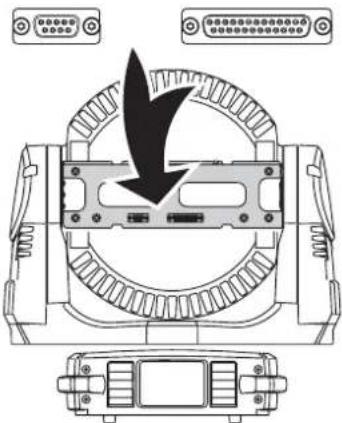
Warning! Attach an approved safety cable to the attachment point on the connections panel (see Figure 2).
Check that all surfaces to be illuminated are minimum 200 mm (8 in.) from the fixture, that combustible materials (wood, fabric, paper, etc.) are minimum 200 mm (8 in.) from the head, that there is free airflow around the fixture and that there are no flammable materials nearby.
Make sure that it is impossible for the moving head to collide with another fixture or other object.
Ensure that wherever the product is installed that people are not able to look directly down the LED beam zone from within a distance of 1 meter (3 feet 4 inches). At less than this distance, the LED emission can cause eye injury or irritation. At distances of 1 meter (3 feet 4 inches) and above, light output is harmless to the naked eye provided that the eye's natural aversion response is not overcome.
Placing the fixture on a flat surface
The MAC 401 can be placed on a stage or other level, flat surface. Check that the surface can support at least 10 times the weight of all fixtures and equipment to be installed on it.

Warning! The supporting surface must be hard and flat or air vents in the base may be blocked, which will cause overheating. Secure the fixture against falling. Attach a securely anchored safety cable to the safety cable attachment point (see Figure 2) if the fixture is to be placed above ground level in any location where it may fall and cause injury or damage.
Mounting the fixture on a truss
The MAC 401 can be clamped to a truss or similar rigging structure in any orientation. Clamp brackets can be attached to the base of the fixture using quarter-turn quick connectors.

Warning! Use two clamps to rig the fixture. Lock each clamp bracket by turning both 1/4-turn fasteners fully clockwise.
To clamp a MAC 401 to a truss:
-
Check that the rigging structure can support at least 10 times the weight of all fixtures and equipment to be installed on it.
-
Obtain two rigging clamps and check that they are undamaged and can bear at least 10 times the weight of the fixture. Bolt the clamps securely to the supplied clamp brackets with a minimum grade 8.8 M12 bolt and lock nut.
-
See Figure 2. Align each of the two clamp brackets with two mounting points in the base. Insert the quarter-turn fasteners into the base and turn all levers a full 90° clockwise to lock.
-
Block access under the work area. Working from a stable platform, hang the fixture on the truss. Tighten the rigging clamps.
-
Secure the fixture against clamp or bracket failure with a secondary attachment such as a safety cable that can bear at least 10 times the weight of the fixture using the attachment point in the base of the fixture (arrowed in Figure 2). This attachment point is designed to accept a carabiner clamp. Do not use any other part of the fixture as a safety cable attachment point.
-
Check that the head will not collide with other fixtures or objects.

Figure 2: Safety cable attachment point

flowchart
graph TD
    A["Lock"] --> B["Target"]
    C["Unlock"] --> B
    B --> D["Return Arrow"]
    style A fill:#f9f,stroke:#333
    style C fill:#f9f,stroke:#333
Figure 3: Quarter-turn fasteners
Setup

Warning! Read "Safety Information" on page 3 before installing, powering, operating or servicing the MAC 401.
Control panel and menu navigation
The onboard control panel and LED display are used to set the MAC 401's DMX address, configure individual fixture settings (personality), read out data and execute service utilities. See “Onboard control menus” on page 36 for a complete list of menus and commands.

A – Four-character LED display
B – Service indicator LED
C – DMX input indicator LED
D - UP button
E - ENTER button
F - DOWN button
G - MENU button
Figure 4: Control panel and display
Using the control buttons
See Figure 4.
- Press [Menu] to enter a menu, to escape a function or move back one level in the menu structure.
- Press the [Up] and [Down] buttons to scroll within a menu or increase and decrease values.
- Press [Enter] to enter a submenu or activate a function. Note: [Enter] must be pressed and held for a few seconds to enter the Service menu (SERV).
Control menu shortcuts
- Hold [Menu] and press [Up] - Resets fixture
- Hold [Menu] and [Enter] during fixture reset - Freezes pan and tilt
- Hold [Up] and press [Down] - Inverts display for easy reading when the fixture is suspended base up.
Display functions
The DMX address is shown in the display panel when the MAC 401 is powered on and has reset.
By default the display is set to go into to sleep mode 2 minutes after the last key press. To reactivate the display, press any key. To modify or disable this setting see "Display settings" on page 17.
LED indicators
The two LEDs on the right of the display indicate fixture status:
- The DMX LED lights when the fixture is receiving a valid DMX signal.
- The SERVICE LED lights if the fixture requires a service intervention. At the same time, a message appears in the display indicating the type of service required.
The SERVICE LED blinks when the fixture is in factory service mode.
Restoring factory default settings
The MAC 401's factory default settings can be restored by scrolling to the main FACT menu, pressing [Enter], opening the FACT submenu and applying a LOAD command.
Three sets of custom user settings can also be stored and recalled from the main FACT menu.
Pixel grouping
In all DMX control modes, the LEDs in the MAC 401 Dual and CT Zoom can be controlled as one single group or split into two or four segments that can be controlled as individual pixels.
The following options are available in the DMX - PGRP submenu:
- 1 – LEDs are divided into four segments A to D, giving Individual control of four pixel groups
- 2V – LEDs are divided vertically into two segments A and B, giving individual control of two pixel groups
- 2H – LEDs are divided horizontally into two segments A and B, giving individual control of two pixel groups
- AII – All LEDs are controlled together as one pixel (this is the default pixel grouping setting).


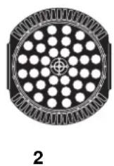
Figure 5: Pixel grouping (fixture standing on base, tilt positive)
Pixel inversion
The DMX - PINV submenu can be used to invert the pixel settings, from left to right and top to bottom.
DMX setup
When one LED module is installed in the front of the head, the MAC 401 automatically sets HEAD to SNGL in the control panel, automatically recognizes the type of module installed and makes the correct DMX protocol available. The module can be controlled using "DMX protocol, RGB Zoom module" on page 25 or "DMX protocol, CT Zoom module" on page 31, depending on which type of module is installed.
If a second LED module is installed on the rear of the head, the MAC 401 automatically sets HEAD to DUAL in the control panel, automatically recognizes the types of module installed and makes the correct DMX protocol available for each module, but it removes the pan, fine pan, tilt, fine tilt and fixture control DMX channels from the protocol for the module installed on the rear of the head. These are only available in the DMX protocol for the module installed on the front of the head.
DMX address setting
The DMX address, also known as the start channel, is the first channel used to receive instructions from the controller. For independent control, each LED module must be assigned its own control channels. Two modules of the same type in the same fixture or in different fixtures may share the same address, however, if identical behavior is desired. Address sharing can be useful for diagnostic purposes and symmetrical control of fixtures, particularly when combined with the inverse pan and tilt options.
The DMX address is configured using the ADDR menu in the control panel. The highest address available is reduced depending on mode settings so that the fixture will always have enough DMX channels in the 512 available in a DMX universe. If the fixture is set up so that it uses 33 DMX channels, for example, the highest address available will be 480.
Whether one or two LED modules are installed on a fixture, all modules' DMX addresses must be set manually using the ADDR menu for that module. You can set the address of each module on the rear of the head immediately after the channels used by the module on the front of that head, or group similar modules together, for example, or set addresses according to any other preference. Table 2 and Table 3 on the following pages can help you determine the number of DMX channels used by a module, if you are in any doubt.
DMX control modes
The MAC 401 can be set to various combinations of DMX control modes using the DMX - PSET menu. Different modes are available for RGB Zoom and CT Zoom LED modules. See "DMX protocols" on page 25 for details of the DMX commands available in the different modes. The MAC 401 automatically recognizes which type of LED modules are fitted to the front and rear and lists only the DMX modes available for those modules:
RGB Zoom module control modes
If an RGB Zoom LED module is installed, it can be set to six DMX control modes in the DMX - PSET menu:
- RAWX – Uncalibrated RGB color mixing with dynamic effects available
- RGBX – Calibrated RGB color mixing with dynamic effects available (this is the default control mode setting)
- HSX – Hue, saturation, value color control with dynamic effects available
- RAW – Uncalibrated RGB color mixing with no dynamic effects available
- RGB – Calibrated RGB color mixing with no dynamic effects available
- HS – Hue, saturation, value color control with no dynamic effects available
CTC (color temperature control) is available in all six modes.
CT Zoom module control modes
If a CT Zoom LED module is installed, it can be set to two DMX control modes in the DMX - PSET submenu:
- CTX – Warm white, cold white, CTC with dynamic effects available (this is the default control mode setting)
- CT – Warm white, cold white, CTC with no dynamic effects available.
One DMX channel between the warm white and cold white channels on CT Zoom modules is left unused so that RGB Zoom and CT Zoom modules use the same number of channels. This avoids the need to repatch lighting desks if one type of LED module is replaced with another.
DMX channel requirements
The number and type of LED modules installed, pixel grouping and control mode determine the number of DMX channels used:
- When two LED modules are installed, the DMX protocol for the module on the rear of the head does not contain coarse and fine pan, coarse and fine tilt or fixture control channels. This module will thus require five less DMX channels than if it was installed on the front of the head.
- The RGB Zoom module uses four channels per pixel group to control Red/Green/Blue/CTC or Hue/Saturation/Value/CTC.
- The CT Zoom module uses four channels per pixel group to control warm white/unused/cold white/CTC.
- No matter which LED module is installed and whether it is installed in the front or rear of the head, pixel group setting PGRP - AII uses four channels, pixel group settings 2H and 2V divide the module into two groups and therefore use eight channels, and pixel group setting 1 divides the module into four groups and therefore uses sixteen channels to control color or color temperature. See “Pixel grouping” on page 13.
- Control modes that incorporate dynamic effects use eight additional DMX channels.
DMX channels used by RGB Zoom module
The following table gives an overview of the control menu settings available and number of DMX channels used in the RGB Zoom module.
| PSET PGRP Mode | Number of channels, front of head | Number of channels, rear of head | ||
| RGB 1 | RGB, no dynamic effects, individual control of 4 quadrant-split LED groups | 25 20 | ||
| RGB 2H | RGB, no dynamic effects, individual control of 2 horizontally split LED groups | 17 12 | ||
| RGB 2V | RGB, no dynamic effects, individual control of 2 vertically split LED groups | 17 12 | ||
| RGB | All | RGB, no dynamic effects, collective control of all LEDs | 13 | 8 |
| HS | 1 | HSV, no dynamic effects, individual control of the 4 quadrant-split LED groups | 25 20 | |
| HS 2H | HSV, no dynamic effects, individual control of 2 horizontally split LED groups | 17 12 | ||
| HS 2V | HSV, no dynamic effects, individual control of 2 vertically split LED groups | 17 12 | ||
| HS All HSV, no dynamic effects, collective control of all LEDs 13 8 | ||||
| RGBX 1 | RGB, dynamic effects, individual control of the 4 quadrant-split LED groups | 33 28 | ||
| RGBX 2H | RGB, dynamic effects, individual control of 2 horizontally split LED groups | 25 20 | ||
| RGBX 2V | RGB, dynamic effects, individual control of 2 vertically split LED groups | 25 20 | ||
| RGBX | All | RGB, dynamic effects, collective control of all LEDs (default setting, RGB Zoom module) | 21 16 | |
| HSX 1 | HSV, dynamic effects, individual control of the 4 quadrant-split LED groups | 33 28 | ||
| HSX 2H | HSV, dynamic effects, individual control of 2 horizontally split LED groups | 25 20 | ||
| HSX 2V | HSV, dynamic effects, individual control of 2 vertically split LED groups | 25 20 | ||
| HSX | All | HSV, dynamic effects, collective control of all LEDs | 21 | 16 |
Table 2: DMX channel use in different mode settings, RGB Zoom module
DMX channels used by CT Zoom module
The following table gives an overview of the control menu settings available and number of channels used in the various modes available in the CT Zoom module.
| PSET PGRP Mode | Number of channels, front of head | Number of channels, rear of head | ||
| CT | 1 | CT, no dynamic effects, individual control of the 4 quadrant-split LED groups | 25 20 | |
| CT 2H | CT, no dynamic effects, individual control of 2 horizontally split LED groups | 17 12 | ||
| CT 2V | CT, no dynamic effects, individual control of 2 vertically split LED groups | 17 12 | ||
| CT | AII | CT, no dynamic effects, collective control of all LEDs | 13 | 8 |
| CTX 1 | CT, dynamic effects, individual control of the 4 quadrant-split LED groups | 33 28 | ||
| CTX 2H | CT, dynamic effects, individual control of 2 horizontally split LED groups | 25 20 | ||
| CTX | 2V | CT, dynamic effects, individual control of 2 vertically split LED groups | 25 20 | |
| CTX | AII | CT, dynamic effects, collective control of all LEDs (default setting, CT Zoom module) | 21 16 | |
Table 3: DMX channel use in different mode settings, CT Zoom module
Tailoring performance
The following performance options are available in the PERS menu.
Pan and tilt movement
The MAC 401 provides several options for optimizing movement for different applications.
- Pan and tilt speed can be set to normal or fast with the PTST - PTSP command.
- The PINV and TINV commands invert the direction of pan and tilt and the SWAP command sets pan commands to tilt and vice versa. These settings are useful for symmetrical effects with multiple fixtures.
Resetting via DMX
By default, it is possible to reset the whole fixture, reset pan and tilt only or reset effects only by sending a DMX command on the Fixture Control DMX channel (the last of the channels used). This feature can be disabled (to avoid accidental resets in the middle of a show, for example) and enabled in the DRES submenu.
If the DMX reset feature is disabled in the DRES submenu, it is still possible to override this setting and reset the fixture via DMX by sending DMX value 232 on channel 2 and DMX value zero on channel 1 before applying the reset command on the Fixture Control channel.
Cooling
The FANS submenu gives you a choice of three cooling fan settings:
- The default setting REG sets fans to temperature-regulated operation. This setting should suit use in all normal situations and ensure excellent service lifetimes for all components.
- The FULL setting maximizes cooling and reduces the operating temperature of the components in the head. It is recommended when the MAC 401 is used intensively in a warm environment or in fixed installations. Note that this setting will give increased fan noise compared to temperature-regulated fan operation.
- When the SLNT setting is selected, Silent mode is activated and head fan speed is reduced to minimum. The base fan will still run. Maximum values allowed for RGB or HSV will be limited (no matter what operating mode is selected), so that less heat is generated. If the LEDs get too hot the fans will revert to Regulated mode. When the LEDs are cool enough the fans shift back to Silent mode. The color wheel channel has lower intensity when Silent mode is engaged.
Whatever cooling mode is selected, a thermal cutout shuts down power to the LEDs if the fixture temperature exceeds safe limits. If this occurs, you must reset the fixture via the control menus or via DMX, or cycle power to the fixture off and on again.
If a thermal shutdown occurs, you are pushing the fixture to its limits. Clean the fixture, particularly the air vents, and check that there is sufficient airflow around the fixture. Consider increasing ventilation, reducing the ambient temperature, or switching to FULL mode.
Dimming
DIM allows you to select a dimming curve for overall intensity. You can choose from an optically linear curve, a square-law curve that gives finer control at low intensity and coarser control at high intensity, an inverse square-law curve, and an S-curve that gives finer control at low and high intensities and coarser control at medium intensities (see Figure 6).
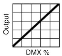

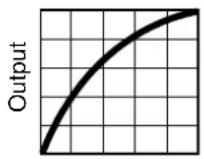

line
| DMX % | Output | |-------|--------| | 0 | 0 | | 100 | 1 |Optically linear S-curveSquare law Inverse square law
Figure 6: Dimming curve options
Display settings
The D I SP submenu can be used to adjust the length of time the display is on before it switches off automatically and goes into Sleep mode. You can also deactivate Sleep mode so that the display remains on all the time.
You can set the intensity level of the display using the DINT submenu. The default is 100%.
Two modes are available for displaying error messages in the ERRM submenu. The default is setting is normal, where error messages appear on the display at 100% intensity (regardless of what the display intensity has been set to), and the service light illuminates. Alternatively, a 'silent' error mode is available, where no error message is displayed, but the service light illuminates.
Effects
MAC 401 - all models
This section describes the lighting effects available in all currently available models of the MAC 401.
Shutter effect
The electronic ‘shutter’ effect provides instant open and blackout, variable speed regular and random strobe, and opening/closing pulse effects.
Dimming
Overall intensity can be adjusted using 0 - 100% electronic dimming.
Zoom
The motorized zoom varies the beam angle continuously from 20^ through to 50^ . The zoom can also be set to Hypermode where the beam angle is fixed at 16^ .
Pan and tilt
The MAC 401 fixture's moving head can be panned through 630^ and tilted through 300^ . Coarse (8-bit/Most Significant Byte) and fine (16-bit/Least Significant Byte) control of pan and tilt are available in all DMX modes. The fine channels allow fine adjustment of pan and tilt at the position set on the coarse channels.
Bear in mind that if two head modules are installed, the second module will point towards the base, and direct light output will be lost, during a portion of its tilt range.
Pre-programmed dynamic effects 1 and 2
Both RGB Zoom and CT Zoom LED modules feature two superimposable dynamic effects. These effects are pre-programmed macros that give quick access to a variety of effects from the DMX controller without the need for complex programming.
Effect crossfade times for the change from one segment to the next can be set from zero (snap) to approximately one second.
Certain effects divide LEDs into two or four segments for a chase that gives a 'pixel wheel' rotation effect.
Pulse, flip and flicker effects are also available.
The speed of the dynamic effects – including rotation speed and direction of the 'pixel wheel' effect – can be adjusted on a separate DMX channel for each of the two dynamic effects.
The dynamic effects have greater visual impact in the RGB Zoom module but can add 'life' to the CT Zoom module.
MAC 401 Dual / RGB Zoom LED module
This section describes the lighting effects available in the RGB LED module that is fitted as standard to the MAC 401 Dual and available as an accessory for the MAC 401 CT Zoom.
Raw RGB color mixing
Uncalibrated red, green, blue color mixing is available, with 0 - 100% intensity control on one DMX channel for each color. Setting a color to 100% intensity will set each LED to its absolute maximum output.
Calibrated RGB color mixing
Red, green, blue color mixing is available, with 0 - 100% calibrated intensity control on one DMX channel for each color. Setting a color to 100% intensity will set each LED to a calibrated maximum output. In other
words, output is very slightly lower than absolute maximum output to allow a margin for adjustment, and LED modules are individually calibrated at the factory to ensure that color and white output is the same in different LED modules at the same DMX values.
Calibrated HSV color mixing
As an alternative to RGB control, hue, saturation and value color control, with one DMX channel for each of these parameters, is available. HSV control is calibrated at the factory.
CTC
From fixture software v. 1.2.0, the MAC 401 Dual's RGB Zoom LED module can vary the color temperature of any color being displayed. White light color temperature is variable from a very cool blue sky (10 000 K) to a warm sunrise (2000 K). The PERS menu contains two settings for the way CTC works:
- If PERS - CTC - WITH (the default setting) is selected, sending a DMX value on the CTC channel will adjust the temperature of whatever color the fixture or segment is currently displaying. The more saturated the color, the less CTC will be noticeable.
- If PERS - CTC - INDP is selected, sending a DMX value on the CTC channel will act independently from color controls, override any currently selected color and the fixture or segment will switch over to white light with variable color temperature.
CTC control is calibrated at the factory. It works in RGB, HSV and RAW modes, but in RAW mode it is uncalibrated.
Color wheel effect
The electronic 'color wheel' effect gives the convenience and feel of a mechanical color wheel. The color wheel effect in the RGB LED module lets you fade or snap between 33 different full LEE-referenced colors. You can also scroll continuously forwards or backwards through the colors or display random colors at variable speed.
The approximate RGB equivalents of the 'color wheel' colors are given in "LEE colors and RGB equivalents" on page 35.
MAC 401 CT Zoom / CT Zoom LED module
This section describes the lighting effects available in the CT Zoom LED module that is fitted as standard to the MAC 401 CT Zoom and available as an accessory for the MAC 401 Dual.
Raw warm white and cold white
The CT Zoom LED module gives separate control of warm white and cold white using two DMX channels. This control mode is raw, so it gives absolute maximum output.
Calibrated color temperature control
CTC can be varied continuously from 7000 K to 3000 K using one DMX channel which mixes cold and warm white LEDs. This control mode is calibrated at the factory, so color temperature will be the same in different modules, but intensity is very slightly reduced compared to raw warm white and cold white mode to allow a margin for adjustment.
Service and maintenance

Warning! Read "Safety Information" on page 3 before servicing the MAC 401.

Warning! Disconnect the fixture from AC mains power and allow to cool for at least 10 minutes before handling. Do not view the light output from less than 1 meter (3 feet 4 inches) without shade 4-5 welding goggles. Set the zoom to wide angle and work in well-lit conditions. Be prepared for the fixture to light suddenly if connected to power.

Warning! Refer any service operation not described in this user manual to a qualified service technician.

Important! Excessive dust, smoke fluid, and particle buildup degrades performance, causes overheating and will damage the fixture. Damage caused by inadequate cleaning or maintenance is not covered by the product warranty.
The user will need to clean the MAC 401 periodically, and it is also possible for the user to remove and install head modules, change the mains fuses and update the firmware. All other service operations on the MAC 401 must be carried out by Martin Professional or its approved service agents.
Installation, on-site service and maintenance can be provided worldwide by the Martin Professional Global Service organization and its approved agents, giving owners access to Martin's expertise and product knowledge in a partnership that will ensure the highest level of performance throughout the product's lifetime. Please contact your Martin supplier for details.
It is Martin policy to apply the strictest possible calibration procedures and use the best quality materials available to ensure optimum performance and the longest possible component lifetimes. However, LEDs are subject to wear and tear over the life of the product, resulting in gradual changes in color and overall brightness over many thousands of hours of use. The extent of wear and tear depends heavily on operating conditions and environment, so it is impossible to specify precisely whether and to what extent LED performance will be affected. However, you may eventually need to ask Martin Professional to replace LEDs if their characteristics are affected by wear and tear after an extended period of use and if you require fixtures to perform within very precise optical and color parameters.
Cleaning
Cleaning schedules for lighting fixtures vary greatly depending on the operating environment. It is therefore impossible to specify precise cleaning intervals for the MAC 401.
Environmental factors that may result in a need for frequent cleaning include:
- Use of smoke or fog machines.
- High airflow rates (near air conditioning vents, for example).
• Presence of cigarette smoke. - Airborne dust (from stage effects, building structures and fittings or the natural environment at outdoor events, for example).
If one or more of these factors is present, inspect fixtures within their first 100 hours of operation to see whether cleaning is necessary. Check again at frequent intervals. This procedure will allow you to assess cleaning requirements in your particular situation. If in doubt, consult your Martin dealer about a suitable

natural_image
Technical diagram of a circular mechanical component with internal holes and a central hub, marked with an arrow (no text or symbols)Figure 7: Head air filter
Use gentle pressure only when cleaning, and work in a clean, well-lit area. Do not use any product that contains solvents or abrasives, as these can cause surface damage.
You can set the fixture to issue a time alert after a defined number of operating hours has passed to remind you to clean it. This is set by default to 999 hours. You can adjust this threshold from 100-999 hours using the INFO - AIRF - STTM menu on the control panel. Whenever the value on the INFO - AIRF - TOTL counter exceeds the threshold set on INFO - AIRF - STTM, an alert will be displayed on the control panel.
Warning! Disconnect from power and allow to cool before cleaning.
To clean the fixture:
- Disconnect the fixture from power and allow it to cool for at least 10 minutes.
- See Figure 7. Unclip and remove the head air filter from the center of the lens plate. Rinse the filter in lukewarm soapy water and blot dry. If the filter is not in perfect condition, replace it with a new one (available from Martin, P/N 62407156).
- Vacuum or gently blow away dust and loose particles from the outside of the fixture and the air vents at the back and sides of the head and in the base with low-pressure compressed air.
-
Clean the front glass by wiping gently with a soft, clean lint-free cloth moistened with a weak detergent solution. Do not rub the surface hard: lift particles off with a soft repeated press. Dry with a soft, clean, lint-free cloth or low-pressure compressed air. Remove stuck particles with an unscented tissue or cotton swab moistened with glass cleaner or distilled water.
-
Reinstall the head air filter.
-
Check that the fixture is dry before reapplying power.
-
Using the INFO-AI RF-TOTL control menu, reset the counter for elapsed time in hours since the fixture was cleaned to 0 by displaying the counter and pressing and holding the up button for five seconds.
Removing and installing head modules
From software version 1.2.0 (available for download free of charge from www.martin.com for fixtures with earlier software versions), two head modules can be installed and controlled in the MAC 401 ^™ .
To remove a head module:.
- Disconnect the fixture from power and allow to cool for at least 10 minutes.
-
See Figure 8. Use a Torx 30 screwdriver to release the four head module retaining screws (arrowed), lift the module away from the yoke slightly, disconnect the head module safety wire and lift the module away from the head.
-
Head module installation procedure is the reverse of the removal procedure. See Figure 9. When installing a module, clip the safety wire into the attachment point in the yoke frame, and make sure that the connectors in the module engage in the connectors in the yoke frame while you press the module into position on the head.
-
The MAC 401 automatically senses which modules are installed when power is applied.


natural_image
Technical diagram of an internal combustion engine cylinder with piston and crankshaft components (no text or labels)Figure 8: Head module removal/installation
Safety wire attachment

natural_image
Technical diagram of a mechanical assembly with gear and housing components, showing a directional arrow (no text or labels)Connectors
natural_image
Technical diagram of a mechanical assembly with labeled components and a black arrow indicating direction (no text or symbols present)Figure 9: Head module safety wire attachment and connectors
Control menu service utilities
Fixture reset
The RST command in the MAN menu resets the fixture and can be used as a first remedy if an error occurs.
Software upload
The MAC 401 software can be installed and updated by the user. Software updates are available for download on the Product Support pages of the Martin website at www.martin.com
The following are required in order to install software:
• A PC running Windows 98/2000/XP
• The latest version of the MAC 401 software, available for download from www.martin.com
• The Martin™ Software Uploader Application, available for download from www.martin.com
- A Martin Universal USB/DMX Interface device (P/N 90702045) with USB cable (supplied with the device) and 5-pin XLR male to 5-pin XLR female DMX cable.
Normal upload
A MAC 401 should automatically enter software upload mode when it is connected as described above. If it does not, use SERV→UPLD in the control menu to prepare the fixture for the upload. Carry out the upload in Auto/DMX mode as described in the Uploader application help file.
If the display and control panel are unusable because the software has become corrupted, carry out a boot mode upload (see below).
Boot mode upload
Carry out a boot mode upload only if the fixture software is totally corrupted (which is evident if the control panel does not respond when power is applied) or if the software update notes call for a boot sector update. To carry out a boot mode upload:
- Disconnect the fixture from power.
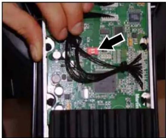
- Remove the left-hand (as seen from the front of the head) side cover from the yoke to expose the main PCB.
- See Figure 10. Locate the 2-pin DIP-switch (arrowed) on the PCB and move pin 1 to ON (Boot mode upload enable).
- Reapply power, upload the software, and disconnect from power.
- Move DIP-switch pin 1 back to OFF (Normal) and reinstall the yoke side cover.
natural_image
Close-up of a hand holding a black cable with a white arrow pointing to a component on a green printed circuit board (no visible text or symbols)Figure 10: 2-pin DIP switch for boot mode upload
If a checksum error occurs when powering on after performing a boot mode upload, carry out a normal upload as described above.
Both DIP-switch pins should be set to OFF during normal operation.
Testing
A series of test commands are available in the TEST menu, these enable:
- Testing the LED effects and zoom only
- Testing pan/tilt movement only
• Lighting all segments of the display for five seconds
- Testing effects (LED and zoom) and pan/tilt movement at same time
Fixture readouts
DMX input signal
The DMXL menu lets you view the DMX values received on each channel. If the fixture does not behave as expected, reading the DMX values can help you troubleshoot the problem.
Fixture status
The MAC 401 gives fixture status readouts in the INFO menu:
- Current software/firmware version information is available for the main processor in the base, and for the processors in each of the installed LED modules (one or two).
- The POHR counters display hours with power on. The RSET counter displays hours since the counter was last reset, and the non-resettable TOTL counter displays hours since the fixture was manufactured.
- Temperature readouts from the main PCB in the base as well as the average temperature of driver and pixel (i.e. LED) PCBs in the head are available. In each case, you can view the current temperature, the maximum temperature reached since the readout was last reset, and the maximum temperature reached since manufacture.
Lubrication
In general, the MAC 401 does not require lubrication. However, depending on use conditions, the moving parts in the head and zoom mechanisms may eventually require reapplication of lubricant. Excessive noise during pan/tilt and zoom movement is a sign that lubrication may be required. This operation can be carried out by a Martin service partner if necessary.
Fuse replacement
Warning! Disconnect from power before replacing a fuse. Replace fuses with ones of the same type and rating only. Never bypass or bridge a fuse.
The MAC 401 is protected by two 10 AT mains fuses located in fuseholders next to the power cable entry (see Figure 1 on page 7).

To replace a fuse:
- Isolate the fixture from power.
- Use a flathead screwdriver to open the fuseholders and remove the fuses for testing or replacement.
- Replace defective fuses with ones of the same type and rating only. Replacement fuses are available from Martin.
- Reinstall the fuseholders before reapplying power.
If a fuse blows repeatedly, disconnect the fixture from power immediately and consult your Martin supplier.
Diagnostic feedback
If an error occurs, one of the following messages may appear in the MAC 401 display:
| Message Cause... | What to do... | |
| AIRF | The AIRFcounter has reached its limit. | Clean the fixture and air filter. Reset the AIRFcounter in the INFO menu. |
| CSER | A fixture firmware upload was unsuccessfuland has resulted in a Checksum Error | Try to upload the firmware again.Contact Martin Service if problem persists. |
| D1COD2COD3COD4CO | Driver PCB 1 temperature cut offDriver PCB 2 temperature cut offDriver PCB 3 temperature cut offDriver PCB 4 temperature cut off | Clean the fixture and air filter and ensureunrestricted airflow around it.Check that ambient temperature does notexceed 40^ C ( 104^ F).Contact Martin Service if problem persists. |
| DTER | Driver temperature sensor error | |
| FTCO | Fixture temperature cutoff | |
| P1COP2COP3COP4CO | Pixel PCB 1 cut-offPixel PCB 2 cut-offPixel PCB 3 cut-offPixel PCB 4 cut-off | |
| PTER | Pixel temperature sensor error | |
| YTCO | Yoke temperature sensor cutoff. Thetemperature has exceeded the allowedmaximum and the LEDs have been switchedoff. | |
| DPER | Display programming error | Reset fixture.Contact Martin Service if problem persists. |
| DREH | Zoom stepper motor driver failure. | |
| F1ERF2ER | Fan 1 errorFan 2 error | |
| FBEP | Pan feedback error. The pan correction systemcould not correct a loss of step. | |
| FBER | Pan/tilt feedback error | |
| FBET | Tilt feedback error. The tilt correction systemcould not correct a loss of step. | |
| MERR | Communication error in EEPROM memory | |
| OPER | Onboard programming error | |
| PAER | Pan timeout error. There is a malfunction in thepan position indexing circuit. | |
| RAME | RAM error | |
| RCER | Real time clock error | |
| RUER | Fixture identification code missing or invalid | |
| TIER | Tilt timeout error. There is a malfunction in thetilt position indexing circuit. | |
| YTER | Yoke temperature circuit error. | |
| RST | Reset. This occurs when power is applied, orwhen reset is selected in the menu. | Wait for reset to finish.Note that you can prevent accidental resets viaDMX by setting PERS - DRES to OFF inthe control menus. |
| SRST | Serial RESET command received via DMX |
DMX protocols
Two DMX protocols are given below: for the MAC 401 RGB Zoom module and CT Zoom module.
Certain channels in the CT Zoom module's DMX protocol are intentionally left without function to avoid having to repatch channels if one type of module is replaced with another.
For each protocol, pan, tilt and fixture control channels are only available if the module is installed on the front of the head. If a module is installed on the rear of the head, control of pan, tilt and fixture functions is not available in that module's DMX protocol. Instead, they must be controlled using the DMX channels for the module installed on the front of the head.
For information about setting up DMX modes, see "DMX setup" on page 13.
DMX protocol, RGB Zoom module
| RAWRGBHS | RAWXRGBXHSX | DMX Value Percent Function | Snap/fade | DefaultDMX value | ||
| 1 | 1 | 0 - 1920 - 4950 - 6465 - 6970 - 8485 - 8990 - 104105 - 109110 - 124125 - 129130 - 144145 - 149150 - 164165 - 169170 - 184185 - 189190 - 204205 - 209210 - 224225 - 229230 - 244245 - 255 | 0 - 78 - 1920 - 2526 - 2728 - 3334 - 3536 - 4142 - 4344 - 4950 - 5152 - 5758 - 5960 - 6566 - 6768 - 7374 - 7576 - 8182 - 8384 - 8990 - 9192 - 9798 - 100 | Strobe/Virtual shutter effectShutter closedShutter openStrobe (fast → slow)Shutter openOpening pulse (fast → slow)Shutter openClosing pulse (fast → slow)Shutter openRandom strobe (fast → slow)Shutter closedRandom opening pulse (fast → slow)Shutter openRandom closing pulse (fast → slow)Shutter closedBurst pulse (fast → slow)Shutter openRandom burst pulse (fast → slow)Shutter closedSine wave (fast → slow)Shutter openElectronic burst (fast → slow)Shutter open | Snap 020 | |
| 2 | 2 | 0 - 255 0 - 100 | Virtual dimmerClosed → open | Fade 0 | ||
| — | 3 | 0 - 19 | 0 - 7 | Dynamic effect 1No EffectEffect 1 - White Single Segment ChaseEffect 2 - White Double Segment ChaseEffect 3 - Red Single Segment ChaseEffect 4 - Green Single Segment ChaseEffect 5 - Blue Single Segment ChaseEffect 6 - Cyan Single Segment ChaseEffect 7 - Magenta Single Segment ChaseEffect 8 - Yellow Single Segment ChaseEffect 9 - Red Double Segment ChaseEffect 10 - Green Double Segment ChaseEffect 11 - Blue Double Segment ChaseEffect 12 - Cyan Double Segment ChaseEffect 13 - Magenta Double Segment ChaseEffect 14 - Yellow Double Segment ChaseEffect 15 - Yellow Blue PulseEffect 16 - Green Magenta PulseEffect 17 - Red Cyan PulseEffect 18 - Red Green PulseEffect 19 - Red Blue PulseEffect 20 - Red Flip 1Effect 21 - Red Flip 2Effect 22 - Green Flip 1Effect 23 - Green Flip 2Effect 24 - Blue Flip 1Effect 25 - Blue Flip 2Effect 26 - White Flip 1Effect 27 - White Flip 2Effect 28 - White Flicker ChaseEffect 29 - Rising PulseEffect 30 - White FlickerEffect 31 - Strobe PulseEffect 32 - Single segment chase (use RGB to set color)Effect 33 - Two segment chase (use RGB to set color)Effect 34 - Double horiz. seg. chase (use RGB to set color)Effect 35 - Double vert. seg. chase (use RGB to set color)Effect 36 - Double opposite chase (use RGB to set color)Effect 37 - Reserved for future useEffect 38 - Reserved for future use | Snap 0 | |
| — | 4 | 0 - 2 | 0 | Dynamic effect 1 speedStopClockwise rotation, fast → slowStopCounter-clockwise rotation, slow → fastStop | Fade 128 | |
| 3 - 126 | 1 - 49 | |||||
| 127 - 129 | 50 | |||||
| 130 - 253 | 51 - 99 | |||||
| 254 - 255 | 100 | |||||
| — | 5 | 0 - 255 0 - 100 | Dynamic effect 1 x-fadeNo fade → max. fade | Fade 0 | ||
| — | 6 | 0 - 255 0 - 100 | Dynamic effect 1 intensityZero → 100% | Fade 0 | ||
| RAW RGB HS | RAWX RGBX HSX | DMX Value | Percent Function | Snap/ fade | Default DMX value | |
| — | 7 | 0 - 19 | 0 - 7 | Dynamic effect 2No EffectEffect 1 - White Single Segment ChaseEffect 2 - White Double Segment ChaseEffect 3 - Red Single Segment ChaseEffect 4 - Green Single Segment ChaseEffect 5 - Blue Single Segment ChaseEffect 6 - Cyan Single Segment ChaseEffect 7 - Magenta Single Segment ChaseEffect 8 - Yellow Single Segment ChaseEffect 9 - Red Double Segment ChaseEffect 10 - Green Double Segment ChaseEffect 11 - Blue Double Segment ChaseEffect 12 - Cyan Double Segment ChaseEffect 13 - Magenta Double Segment ChaseEffect 14 - Yellow Double Segment ChaseEffect 15 - Yellow Blue PulseEffect 16 - Green Magenta PulseEffect 17 - Red Cyan PulseEffect 18 - Red Green PulseEffect 19 - Red Blue PulseEffect 20 - Red Flip 1Effect 21 - Red Flip 2Effect 22 - Green Flip 1Effect 23 - Green Flip 2Effect 24 - Blue Flip 1Effect 25 - Blue Flip 2Effect 26 - White Flip 1Effect 27 - White Flip 2Effect 28 - White Flicker ChaseEffect 29 - Rising PulseEffect 30 - White FlickerEffect 31 - Strobe PulseEffect 32 - Single segment chase (use RGB to set color)Effect 33 - Two segment chase (use RGB to set color)Effect 34 - Double horiz. seg. chase (use RGB to set color)Effect 35 - Double vert. seg. chase (use RGB to set color)Effect 36 - Double opposite chase (use RGB to set color)Effect 37 - Reserved for future useEffect 38 - Reserved for future use | Snap 0 | |
| 20 - 39 | 7 - 16 | |||||
| 40 - 59 | 17 - 24 | |||||
| 60 - 79 | 25 - 32 | |||||
| 80 - 84 | 30 - 31 | |||||
| 85 - 89 | 32 - 33 | |||||
| 90 - 94 | 34 - 35 | |||||
| 95 - 99 | 36 - 37 | |||||
| 100 - 104 | 38 - 39 | |||||
| 105 - 109 | 40 - 41 | |||||
| 110 - 114 | 42 - 43 | |||||
| 115 - 119 | 44 - 45 | |||||
| 120 - 124 | 46 - 47 | |||||
| 125 - 129 | 48 - 49 | |||||
| 130 - 134 | 50 - 51 | |||||
| 135 - 139 | 52 - 53 | |||||
| 140 - 144 | 54 - 55 | |||||
| 145 - 149 | 56 - 57 | |||||
| 150 - 154 | 58 - 59 | |||||
| 155 - 159 | 60 - 61 | |||||
| 160 - 164 | 62 - 63 | |||||
| 165 - 169 | 64 - 65 | |||||
| 170 - 174 | 66 - 67 | |||||
| 175 - 179 | 68 - 69 | |||||
| 180 - 184 | 70 - 71 | |||||
| 185 - 189 | 72 - 73 | |||||
| 190 - 194 | 74 - 75 | |||||
| 195 - 199 | 76 - 77 | |||||
| 200 - 204 | 78 - 79 | |||||
| 205 - 209 | 80 - 81 | |||||
| 210 - 214 | 82 - 83 | |||||
| 215 - 219 | 84 - 85 | |||||
| 220 - 224 | 86 - 87 | |||||
| 225 - 229 | 88 - 89 | |||||
| 230 - 234 | 90 - 91 | |||||
| 235 - 239 | 92 - 93 | |||||
| 240 - 244 | 94 - 95 | |||||
| 245 - 249 | 96 - 97 | |||||
| 250 - 255 | 98 - 100 | |||||
| — | 8 | 0 - 2 | 0 | Dynamic effect 2 speedStopClockwise rotation, fast → slowStopCounter-clockwise rotation, slow → fastStop | Fade 128 | |
| 3 - 126 | 1 - 49 | |||||
| 127 - 129 | 50 | |||||
| 130 - 253 | 51 - 99 | |||||
| 254 - 255 | 100 | |||||
| — | 9 | 0 - 255 0 - 100 | Dynamic effect 2 x-fadeNo fade → max. fade | Fade 0 | ||
| — | 10 | 0 - 255 0 - 100 | Dynamic effect 2 intensityZero → 100% | Fade 0 | ||
| 3 | 11 | 0 - 200 | 0 - 77 | ZoomZoom wide → narrowHypermodeNo function | Fade 0 | |
| 201 - 210 | 78 - 81 | |||||
| 211 - 255 | 82 - 100 | |||||
| 4 | 12 | 0 - 255 0 - 100 | Pan^3 Pan 0 - 630^ (128 = centered) | Fade 128 | ||
| 5 | 13 | 0 - 255 0 - 100 | Pan fine^3 Pan fine (Least Significant Byte) | Fade 0 | ||
| 6 | 14 | 0 - 255 0 - 100 | Tilt^3 Tilt 0 - 300^ (128 = centered) | Fade 128 | ||
| 7 | 15 | 0 - 255 0 - 100 | Tilt fine^3 Tilt fine (Least Significant Byte) | Fade 0 | ||
| RAWRGBHS | RAWXRGBXHSX | DMX Value Percent Function | Snap/fade | DefaultDMX value | ||
| 8 | 16 | 0 - 9 | 0 - 1 | Fixture control ^3 | Snap 0 | |
| 10 - 14 | 2 - 3 | No function | ||||
| 15 - 19 | 4 - 5 | Reset Entire fixture1 | ||||
| 20 - 24 | 6 - 7 | No function | ||||
| 25 - 29 | 8 - 9 | Reset Effects only1 | ||||
| 30 - 34 | 10 - 11 | No function | ||||
| 35 - 39 | 12 - 13 | Reset Pan & Tilt Only1 | ||||
| 40 - 44 | 14 - 15 | No function | ||||
| 45 - 49 | 16 - 17 | PTSP = NORM^2 | ||||
| 50 - 54 | 18 - 19 | PTSP = FAST^2 | ||||
| 55 - 59 | 20 - 21 | No function | ||||
| 60 - 64 | 22 - 23 | Reserved for Future Use | ||||
| 65 - 69 | 24 - 25 | No function | ||||
| 70 - 74 | 26 - 27 | Fan Mode - Full^2 | ||||
| 75 - 79 | 28 - 29 | No function | ||||
| 80 - 84 | 30 - 31 | Fan Mode - Regulated^2 | ||||
| 85 - 89 | 32 - 33 | No function | ||||
| 90 - 94 | 34 - 35 | Fan Mode - Silent^2 | ||||
| 95 - 99 | 36 - 37 | No function | ||||
| 100 - 104 | 38 - 39 | Dimmer Curve = LIN^2 | ||||
| 105 - 109 | 40 - 41 | No function | ||||
| 110 - 114 | 42 - 43 | Dimmer Curve = SQR^2 | ||||
| 115 - 119 | 44 - 45 | No function | ||||
| 120 - 124 | 46 - 47 | Dimmer Curve = ISQR^2 | ||||
| 125 - 129 | 48 - 49 | No function | ||||
| 130 - 249 | 50 - 97 | Dimmer Curve = SCUR^2 | ||||
| 250 - 255 | 98 - 100 | No function, reserved for future use | ||||
| Illuminate Display | ||||||
| 9 | 17 | 0 - 9 | 0 - 1 | Color wheel effectOpen (white)LEE 790 - Moroccan PinkLEE 157 - PinkLEE 332 - Special Rose PinkLEE 328 - Follies PinkLEE 345 - Fuchsia PinkLEE 194 - Surprise PinkLEE 181 - Congo BlueLEE 071 - Tokyo BlueLEE 120 - Deep BlueLEE 079 - Just BlueLEE 132 - Medium BlueLEE 200 - Double CT BlueLEE 161 - Slate BlueLEE 201 - Full CT BlueLEE 202 - Half CT BlueLEE 117 - Steel BlueLEE 353 - Lighter BlueLEE 118 - Light BlueLEE 116 - Medium Blue GreenLEE 124 - Dark GreenLEE 139 - Primary GreenLEE 089 - Moss GreenLEE 122 - Fern GreenLEE 738 - JAS GreenLEE 088 - Lime GreenLEE 100 - Spring YellowLEE 104 - Deep AmberLEE 179 - Chrome OrangeLEE 105 - OrangeLEE 021 - Gold AmberLEE 778 - Millennium GoldLEE 135 - Deep Golden AmberLEE 164 - Flame RedOpen (white)Color wheel rotation effectClockwise, fast → slowColor wheel stop (freezes at current color)Counter-clockwise, slow → fastOpen (white)Random colorFastMediumSlowOpen (white) | Fade 0 | |
| 10 - 14 | 2 - 3 | |||||
| 15 - 19 | 4 - 5 | |||||
| 20 - 24 | 6 - 7 | |||||
| 25 - 29 | 8 - 9 | |||||
| 30 - 34 | 10 - 11 | |||||
| 35 - 39 | 12 - 13 | |||||
| 40 - 44 | 14 - 15 | |||||
| 45 - 49 | 16 - 17 | |||||
| 50 - 54 | 18 - 19 | |||||
| 55 - 59 | 20 - 21 | |||||
| 60 - 64 | 22 - 23 | |||||
| 65 - 69 | 24 - 25 | |||||
| 70 - 74 | 26 - 27 | |||||
| 75 - 79 | 28 - 29 | |||||
| 80 - 84 | 30 - 31 | |||||
| 85 - 89 | 32 - 33 | |||||
| 90 - 94 | 34 - 35 | |||||
| 95 - 99 | 36 - 37 | |||||
| 100 - 104 | 38 - 39 | |||||
| 105 - 109 | 40 - 41 | |||||
| 110 - 114 | 42 - 43 | |||||
| 115 - 119 | 44 - 45 | |||||
| 120 - 124 | 46 - 47 | |||||
| 125 - 129 | 48 - 49 | |||||
| 130 - 134 | 50 - 51 | |||||
| 135 - 139 | 52 - 53 | |||||
| 140 - 144 | 54 - 55 | |||||
| 145 - 149 | 56 - 57 | |||||
| 150 - 154 | 58 - 59 | |||||
| 155 - 159 | 60 - 61 | |||||
| 160 - 164 | 62 - 63 | |||||
| 165 - 169 | 64 - 65 | |||||
| 170 - 174 | 66 - 67 | |||||
| 175 - 179 | 68 - 69 | |||||
| 180 - 201 | 70 - 78 | |||||
| 202 - 207 | 79 - 80 | |||||
| 208 - 229 | 81 - 89 | |||||
| 230 - 234 | 90 - 91 | |||||
| 235 - 239 | 92 - 93 | |||||
| 240 - 244 | 94 - 95 | |||||
| 245 - 249 | 96 - 97 | |||||
| 250 - 255 | 98 - 100 | |||||
Table 4: DMX Protocol, RGB Zoom module
Table 4: DMX Protocol, RGB Zoom module
Table 4: DMX Protocol, RGB Zoom module
Table 4: DMX Protocol, RGB Zoom module
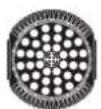
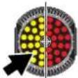
The PGRP option on the control menu on the fixture defines which LEDs the following 4 channels control. See "Pixel grouping" on page 13. The channels can control:
- All of the LEDs (PGRP set to "ALL"), or
- Group A of 2 vertically split LED groups (PGRP set to "2V" and four other channels control the opposite segment), or
- Group A of 2 horizontally split LED groups (PGRP set to "2H" and four other channels control the opposite segment), or
- Group A of 4 quadrant split LED groups (PGRP set to "1" and three groups of four other channels control the other three segments).


| 10 18 | 0 - 255 0 - 100 | Red or Hue (depending on operating mode)Color wheel channel must be set to a DMX value from 0 - 9.Zero → 100% | Fade 0 | |||
| 11 19 | 0 - 255 0 - 100 | Green or Saturation (depending on operating mode)Color wheel channel must be set to a DMX value from 0 - 9.Zero → 100% | Fade 0 | |||
| 12 20 | 0 - 255 0 - 100 | Blue or Value (depending on operating mode)Color wheel channel must be set to a DMX value from 0 - 9.Zero → 100% | Fade 0 | |||
| 13 21 | 0 - 1920 - 255 | 0 - 78 - 100 | CTC (Color Temperature Control)No functionCTC 10 000 K → 2 000 K | Fade 0 | ||
Table 4: DMX Protocol, RGB Zoom module
| RAWRGBHS | RAWXRGBXHSX | DMX Value Percent Function |
Snap/ fade
Default DMX value
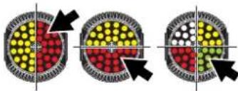
The following block of four channels is only available and used if individual quarter or half groups of LEDs are to be controlled. The level of control is set using the PGRP option on the control menu on the fixture. See "Pixel grouping" on page 13. When available, the channels control:
- Group B of 2 vertically split LED groups (PGRP set to "2V"), or
- Group B of 2 horizontally split LED groups (PGRP set to "2H"), or
- Group B of 4 quadrant split LED groups (PGRP set to "1").
| 14 22 | 0 - 255 0 - 100 | Red or Hue (depending on operating mode)Color wheel channel must be set to a DMX value from 0 - 9.Zero → 100% | Fade 0 | |||
| 15 23 | 0 - 255 0 - 100 | Green or Saturation (depending on operating mode)Color wheel channel must be set to a DMX value from 0 - 9.Zero → 100% | Fade 0 | |||
| 16 24 | 0 - 255 0 - 100 | Blue or Value (depending on operating mode)Color wheel channel must be set to a DMX value from 0 - 9.Zero → 100% | Fade 0 | |||
| 17 25 | 0 - 1920 - 255 | 0 - 78 - 100 | CTC (Color Temperature Control)No functionCTC 10 000 K → 2000 K | Fade 0 | ||
The following four channels are only available and used if individual quarter groups of LEDs are to be controlled (PGRP is set to "1"). The level of control is set using the PGRP option on the control menu on the fixture. See "Pixel grouping" on page 13. The channels control Group C of quadrant split LEDs.

| 18 26 | 0 - 255 0 - 100 | Red or Hue (depending on operating mode)Color wheel channel must be set to a DMX value from 0 - 9.Zero → 100% | Fade 0 | |||
| 19 27 | 0 - 255 0 - 100 | Green or Saturation (depending on operating mode)Color wheel channel must be set to a DMX value from 0 - 9.Zero → 100% | Fade 0 | |||
| 20 28 | 0 - 255 0 - 100 | Blue or Value (depending on operating mode)Color wheel channel must be set to a DMX value from 0 - 9.Zero → 100% | Fade 0 | |||
| 21 29 | 0 - 1920 - 255 | 0 - 78 - 100 | CTC (Color Temperature Control)No functionCTC 10 000 K → 2000 K | Fade 0 | ||
The following four channels are only available and used if individual quarter groups of LEDs are to be controlled (PGRP is set to "1"). The level of control is set using the PGRP option on the control menu on the fixture. See "Pixel grouping" on page 13. The channels control Group D of quadrant split LEDs.

| 22 30 | 0 - 255 0 - 100 | Red or Hue (depending on operating mode)Color wheel channel must be set to a DMX value from 0 - 9.Zero → 100% | Fade 0 | |||
| 23 31 | 0 - 255 0 - 100 | Green or Saturation (depending on operating mode)Color wheel channel must be set to a DMX value from 0 - 9.Zero → 100% | Fade 0 | |||
| 24 32 | 0 - 255 0 - 100 | Blue or Value (depending on operating mode)Color wheel channel must be set to a DMX value from 0 - 9.Zero → 100% | Fade 0 | |||
| 25 33 | 0 - 1920 - 255 | 0 - 78 - 100 | CTC (Color Temperature Control)No functionCTC 10 000 K → 2000 K | Fade 0 | ||
Table 4: DMX Protocol, RGB Zoom module
^1 If DMX Reset is disabled in the onboard control menus, a reset command can only be executed if channel 2 is set to DMX value 232 and channel 1 is set to zero.
^2 Menu override. Setting unaffected by power off/on
^3 If an RGB Zoom module is fitted to the rear of the head, the pan/tilt and fixture control channels have no effect.
DMX protocol, CT Zoom module
| CT | CTX | DMX Value | Percent Function | Snap/ fade | Default DMX value | |
| 1 | 1 | 0 - 1920 - 4950 - 6465 - 6970 - 8485 - 8990 - 104105 - 109110 - 124125 - 129130 - 144145 - 149150 - 164165 - 169170 - 184185 - 189190 - 204205 - 209210 - 224225 - 229230 - 244245 - 255 | 0 - 78 - 1920 - 2526 - 2728 - 3334 - 3536 - 4142 - 4344 - 4950 - 5152 - 5758 - 5960 - 6566 - 6768 - 7374 - 7576 - 8182 - 8384 - 8990 - 9192 - 9798 - 100 | Strobe/Virtual shutter effectShutter closedShutter openStrobe (fast → slow)Shutter openOpening pulse (fast → slow)Shutter openClosing pulse (fast → slow)Shutter openRandom strobe (fast → slow)Shutter closedRandom opening pulse (fast → slow)Shutter openRandom closing pulse (fast → slow)Shutter closedBurst pulse (fast → slow)Shutter openRandom burst pulse (fast → slow)Shutter closedSine wave (fast → slow)Shutter openElectronic burst (fast → slow)Shutter open | Snap 020 | |
| 2 | 2 | 0 - 255 0 - 100 | Virtual dimmerClosed → open | Fade 0 | ||
| — | 3 | 0 - 1920 - 3940 - 5960 - 189190 - 194195 - 199200 - 204205 - 209210 - 214215 - 219220 - 224225 - 229230 - 234235 - 239240 - 244245 - 249250 - 255 | 0 - 77 - 1617 - 2425 - 7374 - 7576 - 7778 - 7980 - 8182 - 8384 - 8586 - 8788 - 8990 - 9192 - 9394 - 9596 - 9798 - 100 | Dynamic effect 1No EffectEffect 1 - White Single Segment ChaseEffect 2 - White Double Segment ChaseNo EffectEffect 3 - White Flip 1Effect 4 - White Flip 2Effect 5 - White Flicker ChaseEffect 6 - Rising PulseEffect 7 - White FlickerEffect 8 - Strobe PulseEffect 9 - Single segment chase (set color temperature using Warm/Cold or CT)Effect 10 - Two segment chase (set color temperature using Warm/Cold or CT)Effect 11 - Double horiz. seg. chase (set color temperature using Warm/Cold or CT)Effect 12 - Double vert. seg. chase (set color temperature using Warm/Cold or CT)Effect 13 - Double opposite chase (set color temperature using Warm/Cold or CT)Effect 14 - Reserved for future useEffect 15 - Reserved for future use | Snap 0 | |
| — | 4 | 0 - 23 - 126127 - 129130 - 253254 - 255 | 01 - 495051 - 99100 | Dynamic effect 1 speedStopClockwise rotation, fast → slowStopCounter-clockwise rotation, slow → fastStop | Fade 128 | |
| — | 5 | 0 - 255 0 - 100 | Dynamic effect 1 x-fadeNo fade → max. fade | Fade 0 | ||
| — | 6 | 0 - 255 0 - 100 | Dynamic effect 1 intensityZero → 100% | Fade 0 | ||
| — | 7 | 0 - 1920 - 3940 - 5960 - 189190 - 194195 - 199200 - 204205 - 209210 - 214215 - 219220 - 224225 - 229230 - 234235 - 239240 - 244245 - 249250 - 255 | 0 - 77 - 1617 - 2425 - 7374 - 7576 - 7778 - 7980 - 8182 - 8384 - 8586 - 8788 - 8990 - 9192 - 9394 - 9596 - 9798 - 100 | Dynamic effect 2No effectEffect 1 - White Single Segment ChaseEffect 2 - White Double Segment ChaseNo effectEffect 3 - White Flip 1Effect 4 - White Flip 2Effect 5 - White Flicker ChaseEffect 6 - Rising PulseEffect 7 - White FlickerEffect 8 - Strobe PulseEffect 9 - Single segment chase (set color temperature using Warm/Cold or CT)Effect 10 - Two segment chase (set color temperature using Warm/Cold or CT)Effect 11 - Double horiz. seg. chase (set color temperature using Warm/Cold or CT)Effect 12 - Double vert. seg. chase (set color temperature using Warm/Cold or CT)Effect 13 - Double opposite chase (set color temperature using Warm/Cold or CT)Effect 14 - Reserved for future useEffect 15 - Reserved for future use | Snap 0 | |
| — | 8 | 0 - 23 - 126127 - 129130 - 253254 - 255 | 01 - 495051 - 99100 | Dynamic effect 2 speedStopClockwise rotation, fast → slowStopCounter-clockwise rotation, slow → fastStop | Fade 128 | |
| — | 9 | 0 - 255 0 - | 100 | Dynamic effect 2 x-fadeNo fade → max. fade | Fade 0 | |
| — | 10 | 0 - 255 0 - | 100 | Dynamic effect 2 intensityZero → 100% | Fade 0 | |
| 3 | 11 | 0 - 200201 - 210211 - 255 | 0 - 7778 - 8182 - 100 | ZoomZoom wide → narrowHypermodeNo function | Fade 0 | |
| 4 | 12 | 0 - 255 0 - | 100 | Pan^3 Pan 0 - 630° (128 = centered) | Fade 128 | |
| 5 | 13 | 0 - 255 0 - | 100 | Pan fine^3 Pan fine (Least Significant Byte) | Fade 0 | |
| 6 | 14 | 0 - 255 0 - | 100 | Tilt^3 Tilt 0 - 300° (128 = centered) | Fade 128 | |
| 7 | 15 | 0 - 255 0 - | 100 | Tilt fine^3 Tilt fine (Least Significant Byte) | Fade 0 | |
| CT | CTX | DMX Value Percent Function | Snap/ fade | Default DMX value | ||
| 8 | 16 | 0 - 9 | 0 - 1 | Fixture control ^3 | Snap 0 | |
| 10 - 14 | 2 - 3 | No function | ||||
| 15 - 19 | 4 - 5 | Reset Entire fixture1 | ||||
| 20 - 24 | 6 - 7 | No function | ||||
| 25 - 29 | 8 - 9 | Reset Effects only1 | ||||
| 30 - 34 | 10 - 11 | No function | ||||
| 35 - 39 | 12 - 13 | Reset Pan & Tilt Only1 | ||||
| 40 - 44 | 14 - 15 | No function | ||||
| 45 - 49 | 16 - 17 | PTSP = NORM^2 | ||||
| 50 - 54 | 18 - 19 | PTSP = FAST^2 | ||||
| 55 - 59 | 20 - 21 | No function | ||||
| 60 - 64 | 22 - 23 | Reserved for Future Use | ||||
| 65 - 69 | 24 - 25 | No function | ||||
| 70 - 74 | 26 - 27 | Fan Mode - Full^2 | ||||
| 75 - 79 | 28 - 29 | No function | ||||
| 80 - 84 | 30 - 31 | Fan Mode - Regulated^2 | ||||
| 85 - 89 | 32 - 33 | No function | ||||
| 90 - 94 | 34 - 35 | Fan Mode - Silent^2 | ||||
| 95 - 99 | 36 - 37 | No function | ||||
| 100 - 104 | 38 - 39 | Dimmer Curve = LIN^2 | ||||
| 105 - 109 | 40 - 41 | No function | ||||
| 110 - 114 | 42 - 43 | Dimmer Curve = SQR^2 | ||||
| 115 - 119 | 44 - 45 | No function | ||||
| 120 - 124 | 46 - 47 | Dimmer Curve = ISQR^2 | ||||
| 125 - 129 | 48 - 49 | No function | ||||
| 130 - 249 | 50 - 97 | Dimmer Curve = SCUR^2 | ||||
| 250 - 255 | 98 - 100 | No function, reserved for future use | ||||
| Illuminate Display | ||||||
| 9 | 17 | Channel not used | ||||
Table 5: DMX Protocol, CT Zoom module
Table 5: DMX Protocol, CT Zoom module
The PGRP option in the control menu for the module defines which LEDs the following 4 channels control. See "Pixel grouping" on page 13. The channels can control:
- All of the LEDs (PGRP set to "ALL"), or
- Group A of 2 vertically split LED groups (PGRP set to "2V" and four other channels control the opposite segment), or
- Group A of 2 horizontally split LED groups (PGRP set to "2H" and four other channels control the opposite segment), or
- Group A of 4 quadrant split LED groups (PGRP set to "1" and three groups of four other channels control the other three segments).
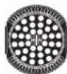
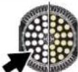


| 10 18 | 0 - 255 0 - 100 | Warm white – rawCTC channel must be set to a DMX value from 0 - 19.Zero → 100% | Fade 0 | |||
| 11 19 | Channel not used | |||||
| 12 20 | 0 - 255 0 - 100 | Cold white – rawCTC channel must be set to a DMX value from 0 - 9.Zero → 100% | Fade 0 | |||
| 13 21 | 0 - 1920 - 255 | 0 - 78 - 100 | CTC (Color Temperature Control) – calibratedNo function, Warm and Cold channels (10 and 12 in CT mode/18 and 20 in CTX mode) enabledCTC 7 000 K → 3 000 K, Warm and Cold channels disabled | Fade 0 | ||
The following block of four channels is only available and used if individual quarter or half groups of LEDs are to be controlled. The level of control is set using the PGRP option in the control menu for the module. See "Pixel grouping" on page 13. When available, the channels control:
- Group B of 2 vertically split LED groups (PGRP set to "2V"), or
- Group B of 2 horizontally split LED groups (PGRP set to "2H"), or
- Group B of 4 quadrant split LED groups (PGRP set to "1").
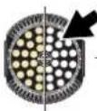
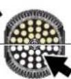

| 14 22 | 0 - 255 0 - 100 | Warm white – rawCTC channel must be set to a DMX value from 0 - 19.Zero → 100% | Fade 0 | |||
| 15 23 | Channel not used | |||||
| 16 24 | 0 - 255 0 - 100 | Cold white – rawCTC channel must be set to a DMX value from 0 - 9.Zero → 100% | Fade 0 | |||
| CT | CTX | DMX Value Percent Function | Snap/ fade | Default DMX value | ||
| 17 25 | 0 - 19 | 0 - 7 | CTC (Color Temperature Control) – calibratedNo function, Warm and Cold channels (14 and 16 in CT mode/22 and 24 in CTX mode) enabledCTC 7 000 K → 3 000 K, Warm and Cold channels disabled | Fade 0 | ||
| 20 - 255 | 8 - 100 | |||||
Table 5: DMX Protocol, CT Zoom module
The following four channels are only available and used if individual quarter groups of LEDs are to be controlled (PGRP is set to "1"). The level of control is set using the PGRP option in the control menu for the module. See "Pixel grouping" on page 13. The channels control Group C of quadrant split LEDs.

| 18 26 | 0 - 255 0 - 100 | Warm white – rawCTC channel must be set to a DMX value from 0 - 19.Zero → 100% | Fade 0 | |||
| 19 27 | Channel not used | |||||
| 20 28 | 0 - 255 0 - 100 | Cold white – rawCTC channel must be set to a DMX value from 0 - 9.Zero → 100% | Fade 0 | |||
| 21 29 | 0 - 1920 - 255 | 0 - 78 - 100 | CTC (Color Temperature Control) – calibratedNo function, Warm and Cold channels (18 and 20 in CT mode/26 and 28 in CTX mode) enabledCTC 7 000 K → 3 000 K, Warm and Cold channels disabled | Fade 0 | ||
The following four channels are only available and used if individual quarter groups of LEDs are to be controlled (PGRP is set to "1"). The level of control is set using the PGRP option in the control menu for the module. See "Pixel grouping" on page 13. The channels control Group D of quadrant split LEDs.
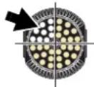
| 22 30 | 0 - 255 0 - 100 | Warm white – rawCTC channel must be set to a DMX value from 0 - 19.Zero → 100% | Fade 0 | |||
| 23 31 | Channel not used | |||||
| 24 32 | 0 - 255 0 - 100 | Cold white – rawCTC channel must be set to a DMX value from 0 - 9.Zero → 100% | Fade 0 | |||
| 25 33 | 0 - 1920 - 255 | 0 - 78 - 100 | CTC (Color Temperature Control) – calibratedNo function, Warm and Cold channels (22 and 24 in CT mode/30 and 32 in CTX mode) enabledCTC 7 000 K → 3 000 K, Warm and Cold channels disabled | Fade 0 | ||
Table 5: DMX Protocol, CT Zoom module
^1 If DMX Reset is disabled in the onboard control menus, a reset command can only be executed if channel 2 is set to DMX value 232 and channel 1 is set to zero.
^2 Menu override. Setting unaffected by power off/on
^3 If a CT Zoom module is fitted to the rear of the head, the pan/tilt and fixture control channels have no effect.
LEE colors and RGB equivalents
The table below gives approximate RGB equivalents for the LEE colors available in the RGB Zoom module's color wheel effect (DMX channel 9).
DMX Integer
| Lee no. Name Red Green Blue | |
| 790 Moroccan Pink 255 062 014 | |
| 157 Pink 255 033 010 | |
| 332 Special rose Pink 255 001 012 | |
| 328 Follies Pink 255 013 025 | |
| 345 Fuchsia Pink 255 046 063 | |
| 194 Surprise Pink 255 081 068 | |
| 181 Congo Blue 092 002 255 | |
| 071 Tokyo Blue | 030 000 255 |
| 120 Deep Blue | 019 026 255 |
| 079 Just Blue | 031 093 255 |
| 132 Medium Blue | 022 161 255 |
| 200 Double CT Blue | 255 182 200 |
| 161 State Blue | 255 221 183 |
| 201 Full CT Blue | 255 135 075 |
| 202 Half CT Blue | 255 118 045 |
| 117 Steel Blue | 255 165 059 |
| 353 Lighter Blue | 214 255 123 |
| 118 Light Blue | 074 255 186 |
| 116 Medium Blue Green | 000 255 112 |
| 124 Dark Green | 069 255 015 |
| 139 Primary Green | 058 255 000 |
| 089 Moss Green | 198 255 008 |
| 122 Fern Green 251 255 012 | |
| 738 JAS Green | 255 228 000 |
| 088 Lime Green 255 138 003 | |
| 100 Spring Yellow 255 101 000 | |
| 104 Deep Amber | 255 070 000 |
| 179 Chrome Orange | 255 056 000 |
| 105 Orange | 255 042 000 |
| 021 Gold Amber | 255 031 000 |
| 778 Millennium Gold | 255 025 000 |
| 135 Deep Golden Amber | 255 017 000 |
| 164 Flame Red | 255 010 001 |
Onboard control menus
Single head module operation
When only one module is installed on the head, the HEAD menu is automatically set to SNGL. The MAC 401 automatically detects whether an RGB Zoom or CT Zoom module is installed and adjusts the control menu accordingly. The following control menus are available:
Menu Item Options Notes (Default settings in bold print)
| ADDR | 1 - XXX | DMX address (default address = 1). The DMX address range is limited so that the fixture will always have enough DMX channels in the 512 available. | |
| DMX | PSET (fixture auto-detects which module is installed and displays either RGB/HS ^1 or CT ^2 menu items) | RAWX | Non-calibrated RGB mode with dynamic effects ^1 |
| RGBX | Calibrated RGB mode with dynamic effects ^1 | ||
| HSX | HSV mode with dynamic effects ^1 | ||
| RAW | Non-calibrated RGB mode without dynamic effects ^1 | ||
| RGB | Calibrated RGB mode without dynamic effects ^1 | ||
| HS | HSV mode without dynamic effects ^1 | ||
| CTX | CT mode with dynamic effects ^2 | ||
| CT | CT mode without dynamic effects ^2 | ||
| PGRP | 1 | Individual control of 4 pixels (segments) | |
| 2H | Control of pixels in 2 groups of 2 pixels, horizontal split | ||
| 2V | Control of pixels in 2 groups of 2 pixels, vertical split | ||
| All | All pixels controlled as one group | ||
| PINV | OFF | Disable pixel inversion | |
| ON | Pixel inversion: pixels swapped left to right and top to bottom | ||
| PERS | PTST | PTSP | Pan and tilt speed normal / fast |
| SWAP | Swap pan and tilt (pan commands move tilt and vice versa) - off / on | ||
| PINV | Pan inversion (reverse direction pan control) - off / on | ||
| TINV | Tilt inversion (reverse direction tilt control) - off / on | ||
| FANS | REG | Cooling fan speed thermostatically regulated | |
| FULL | Max. cooling fan speed | ||
| SLNT | Silent mode. When Silent mode is selected the head fan will turn off. The base fan will still run. Values allowed for RGB or HSV (no matter what operating mode) will be limited to prevent the fixture from producing too much heat. If the LEDs get too hot the fans will revert to Regulated mode. When the LEDs are cool enough the fans shift back to Silent mode. The color wheel channel will have lower intensity in Silent mode. | ||
| DIM | LIN | Linear dimming curve | |
| SQR | Square law dimming curve | ||
| ISQR | Inverse square law dimming curve | ||
| SCUR | S-curve dimming curve | ||
| DRES | OFF | Disable reset via DMX | |
| ON | Enable reset via DMX | ||
| DISP | ON | Display is permanently on | |
| 2MN | Display switches off and goes into Sleep mode if controls have not been pressed for 2 minutes. | ||
| 5MN | Display switches off and goes into Sleep mode if controls have not been pressed for 5 minutes | ||
| 10MN | Display switches off and goes into Sleep mode if controls have not been pressed for 10 minutes | ||
| DINT 0-100 | Display intensity. Default = 100% | ||
| ERRM | NORM | Display errors at 100% intensity (regardless of DINT setting) and illuminate the service light. | |
| SLNT | Silent error mode. The error message does not appear in the display, but the service lamp is illuminated | ||
| CTC (RGB Zoom module only) | WITH | Sending a value on a CTC channel adjusts the temperature of whatever color is currently being displayed on segment or fixture | |
| INDP | Sending a value on a CTC channel overrides any color being displayed. Fixture or segment switches to white with variable color temperature | ||
Table 6: Control menu: single head module operation
Menu Item Options Notes (Default settings in bold print)
| FACT | FACT LOAD | Return all settings (except calibrations) to factory defaultsNB: can take up to 2 minutes to complete! | |
| CUS1,CUS2,CUS3 | LOAD | Load custom configuration | |
| SAVE | Save current custom configuration | ||
| INFO | VERS | MAIN | CPU firmware version in main processor |
| HEAD | CPU firmware version in head processor front module (shows N/A if rear module not installed) | ||
| POHR | RSET | Hours of operation since counter reset (to reset counter, display counter and press [Up] for 5 secs.) | |
| TOTL | Total hours of operation since manufacture | ||
| MTMP | CURR | Display current main PCB temperature | |
| MSR | Display highest main PCB temperature since last reset | ||
| MR | Display highest main PCB temperature since manufacture | ||
| DTMP | CURR | Display current average driver PCB temperature | |
| MSR | Display highest driver PCB temperature since last reset | ||
| MR | Display highest driver PCB temperature since manufacture | ||
| PTMP | CURR | Display current average pixel PCB temperature | |
| MSR | Display highest pixel PCB temperature since last reset | ||
| MR | Display highest pixel PCB temperature since manufacture | ||
| AIRF | TOTL | Current elapsed time in hours since the air filter was cleaned or changed. Display the counter and press the up button for five seconds to reset it. This counter must be reset manually when the air filter is cleaned. | |
| STTM | Set duration of time alert to be issued after 100-9999 hours have passed on the TOTL counter to remind you to clean it, particularly the air filter. The alert appears as long as the value of the TOTL counter is higher than the threshold set here. Default value = 0999 | ||
| SNUM | RDM | Display fixture's RDM ID | |
| SNUM | Display fixture's serial number | ||
| MAN | RST | Reset fixture. Press [Enter] to confirm | |
| ALL 0 - 255 | All LEDs, intensity 0 - 100% | ||
| RED or WARM | 0 - 255 | Red if RGB module installed, Warm white if CT module installed, intensity 0 - 100% | |
| GRN1 0 - 255 | Green 1 if RGB module installed, intensity 0 - 100%Not displayed if CT module installed | ||
| GRN2 0 - 255 | Green 2 if RGB module installed, intensity 0 - 100%Not displayed if CT module installed | ||
| BLUE or COLD | 0 - 255 | Blue if RGB module installed, Cold white if CT module installed, intensity 0 - 100% | |
| ZOOM 0 - 255 | Zoom full wide → zoom full narrow (Hypermode) | ||
| PAN 0 - 255 | Pan full left → pan full right | ||
| TILT 0 - 255 | Full tilt → full opposite tilt | ||
| TEST | TALL | Test LEDs, zoom and pan/tilt movement | |
| T-FX | Test LEDs and zoom only | ||
| TP-T | Test pan/tilt movement only | ||
| TDIS | Light all segments in onboard display panel for 5 secs. | ||
| DMXL | RATE | DMX transmission speed, live, in packets per second | |
| QUAL | Percent of packets received with errors, live | ||
| STRT | Decimal value of the DMX start code, live | ||
| SHUT - FIXT SET | 0 - 255 | DMX value received on each channel | |
| SERVTo access this menu, hold[Enter]pressed for a few seconds | PTFB | ON | Enable pan/tilt position feedback/correction system |
| OFF | Disable pan/tilt feedback for servicing (this setting is not saved when fixture is reset) | ||
| ADJ | Effects adjustment menu (for service use: for full details of this menu, see "Adjustment submenu" on page 42) | ||
| CAL(OF = offset) | P OF | Pan calibration 0 - 255 | |
| T OF | Tilt calibration 0 - 255 | ||
| DOF SURE | Load factory effects calibration settings | ||
| PCBT SURE | PCB test: for service use only | ||
| UPLD SURE | Manually set fixture to receive software upload | ||
Table 6: Control menu: single head module operation
Menu Item Options Notes (Default settings in bold print)
| HEAD | DUAL | Sets head to dual head module operation |
| SNGL | Sets head to single head module operation |
Table 6: Control menu: single head module operation
Dual head module operation
When you install a second head module on the rear of the head, DUAL is automatically selected in the HEAD menu and FRNT and REAR menus become available in the control panel:
- If the FRNT menu is selected, the commands you enter are applied to the front head module.
- If the REAR menu is selected, the commands you enter are applied to the rear head module.
- The PERS, FACT, DMXL, SERV and HEAD menus apply to the entire fixture.
As with single head module operation, the MAC 401 automatically detects whether an RGB Zoom or CT Zoom module is installed on the front and the rear of the head and adjusts the control menus accordingly. The following control menus are available:
Menu Item Item Options Notes (Default settings in bold print)
| FRNT | ADDR | 1 - XXX | DMX address of module on front of head (default address = 1). The DMX address range is limited so that the fixture will always have enough DMX channels in the 512 available. | |
| DMX | PSET (fixture auto-detects which module is installed and displays either RGB/HS ^1 or CT ^2 menu items) | RAW X | Non-calibrated RGB mode with dynamic effects ^1 | |
| RGBX | Calibrated RGB mode with dynamic effects ^1 | |||
| HSX | HSV mode with dynamic effects ^1 | |||
| RAW | Non-calibrated RGB mode without dynamic effects ^1 | |||
| RGB | Calibrated RGB mode without dynamic effects ^1 | |||
| HS | HSV mode without dynamic effects ^1 | |||
| CTX | CT mode with dynamic effects ^2 | |||
| CT | CT mode without dynamic effects ^2 | |||
| PGRP | 1 | Individual control of 4 pixels (segments) | ||
| 2H | Control of pixels in 2 groups of 2 pixels, horizontal split | |||
| 2V | Control of pixels in 2 groups of 2 pixels, vertical split | |||
| All | All pixels controlled as one group | |||
| PI NV | OFF | Disable pixel inversion | ||
| ON | Pixel inversion: pixels swapped left to right and top to bottom | |||
| INFO | VERS | MAIN | CPU firmware version in main processor | |
| HEAD | CPU firmware version in head processor front module / rear module (if installed) | |||
| POHR | RSET | Hours of operation since counter reset (to reset counter, display counter and press [Up] for 5 secs.) | ||
| TOTL | Total hours of operation since manufacture | |||
| MTMP | CURR | Display current main PCB temperature | ||
| MSR | Display highest main PCB temperature since last reset | |||
| MR | Display highest main PCB temperature since manufacture | |||
| DTMP | CURR | Display current average driver PCB temperature | ||
| MSR | Display highest driver PCB temperature since last reset | |||
| MR | Display highest driver PCB temperature since manufacture | |||
| PTMP | CURR | Display current average pixel PCB temperature | ||
| MSR | Display highest pixel PCB temperature since last reset | |||
| MR | Display highest pixel PCB temperature since manufacture | |||
Table 7: Control menu: dual head module operation
Menu Item Item Options Notes (Default settings in bold print)
| FRNT(continued) | INFO(continued) | AIRF | TOTL | Current elapsed time in hours since the air filter was cleaned or changed. Display the counter and press the up button for five seconds to reset it. This counter must be reset manually when the air filter is cleaned. |
| STTM | Set duration of time alert to be issued after 100-9999 hours have passed on the TOTL counter to remind you to clean it, particularly the air filter. The alert appears as long as the value of the TOTL counter is higher than the threshold set here. Default value = 0999 | |||
| SNUM | RDM | Display fixture's RDM ID (this will be the same in the REAR menu) | ||
| SNUM | Display fixture's serial number (this will be the same in the REAR menu) | |||
| MAN | RST | Reset fixture. Press [Enter] to confirm | ||
| ALL 0 - 255 | All LEDs, intensity 0 - 100% | |||
| RED or WARM | 0 - 255 | Red if RGB module installed, Warm white if CT module installed, intensity 0 - 100% | ||
| GRN1 0 - 255 | Green 1 if RGB module installed, intensity 0 - 100%Not displayed if CT module installed | |||
| GRN2 0 - 255 | Green 2 if RGB module installed, intensity 0 - 100%Not displayed if CT module installed | |||
| BLUE or COLD | 0 - 255 | Blue if RGB module installed, Cold white if CT module installed, intensity 0 - 100% | ||
| ZOOM 0 - 255 | Zoom full wide → zoom full narrow (Hypermode) | |||
| TILT 0 - 255 | Full tilt → full opposite tilt | |||
| PAN 0 - 255 | Pan full left → pan full right | |||
| TEST | TALL | Test LEDs, zoom and pan/tilt movement | ||
| T-FX | Test LEDs and zoom only | |||
| TP-T | Test pan/tilt movement only | |||
| TDIS | Light all segments in onboard display panel for 5 secs. | |||
| REAR | ADDR | 1 - XXX | DMX address of module on rear of head (default address = 1). The DMX address range is limited so that the fixture will always have enough DMX channels in the 512 available. | |
| PSET (fixture auto-detects which module is installed and displays either RGB/HS1 or CT2 menu items) | RAWX | Non-calibrated RGB mode with dynamic effects1 | ||
| RGBX | Calibrated RGB mode with dynamic effects1 | |||
| HSX | HSV mode with dynamic effects1 | |||
| RAW | Non-calibrated RGB mode without dynamic effects1 | |||
| RGB | Calibrated RGB mode without dynamic effects1 | |||
| HS | HSV mode without dynamic effects1 | |||
| CTX | CT mode with dynamic effects2 | |||
| CT | CT mode without dynamic effects2 | |||
| PGRP | 1 | Individual control of 4 pixels (segments) | ||
| 2H | Control of pixels in 2 groups of 2 pixels, horizontal split | |||
| 2V | Control of pixels in 2 groups of 2 pixels, vertical split | |||
| All | All pixels controlled as one group | |||
| PINV | OFF | Disable pixel inversion | ||
| ON | Pixel inversion: pixels swapped left to right and top to bottom | |||
| INFO | VERS | MAIN | CPU firmware version in main processor | |
| HEAD | FRNT = CPU firmware version in head processor front module REAR = CPU firmware version in head processor rear module (shows N/A if rear module not installed) | |||
| POHR | RSET | Hours of operation since counter reset (to reset counter, display counter and press [Up] for 5 secs.) | ||
| TOTL | Total hours of operation since manufacture | |||
| MTMP | CURR | Display current main PCB temperature | ||
| MSR | Display highest main PCB temperature since last reset | |||
| MR | Display highest main PCB temperature since manufacture | |||
| DTMP | CURR | Display current average driver PCB temperature | ||
| MSR | Display highest driver PCB temperature since last reset | |||
| MR | Display highest driver PCB temperature since manufacture | |||
Table 7: Control menu: dual head module operation
Menu Item Item Options Notes (Default settings in bold print)
| REAR (continued) | INFO (continued) | PTMP | CURR | Display current average pixel PCB temperature |
| MSR | Display highest pixel PCB temperature since last reset | |||
| MR | Display highest pixel PCB temperature since manufacture | |||
| AI RF | TOTL | Current elapsed time in hours since the air filter was cleaned or changed. Display the counter and press the up button for five seconds to reset it. This counter must be reset manually when the air filter is cleaned. | ||
| STTM | Set duration of time alert to be issued after 100-9999 hours have passed on the TOTL counter, to remind you to clean it, particularly the air filter. The alert appears as long as the value of the TOTL counter is higher than the threshold set here. | |||
| SNUM | RDM | Display fixture's RDM ID (this will be the same in the FRNT menu) | ||
| SNUM | Display fixture's serial number (this will be the same in the FRNT menu) | |||
| MAN | RST | Reset fixture. Press [Enter] to confirm | ||
| ALL 0 - 255 | All LEDs, intensity 0 - 100% | |||
| RED or WARM | 0 - 255 | Red if RGB module installed, Warm white if CT module installed, intensity 0 - 100% | ||
| GRN1 0 - 255 | Green 1 if RGB module installed, intensity 0 - 100%Not displayed if CT module installed | |||
| GRN2 0 - 255 | Green 2 if RGB module installed, intensity 0 - 100%Not displayed if CT module installed | |||
| BLUE or COLD | 0 - 255 | Blue if RGB module installed, Cold white if CT module installed, intensity 0 - 100% | ||
| ZOOM 0 - 255 | Zoom full wide → zoom full narrow (Hypermode) | |||
| TILT 0 - 255 | Full tilt → full opposite tilt | |||
| PAN 0 - 255 | Pan full left → pan full right | |||
| TEST | TALL | Test LEDs, zoom and pan/tilt movement | ||
| T-FX | Test LEDs and zoom only | |||
| TP-T | Test pan/tilt movement only | |||
| TDIS | Light all segments in onboard display panel for 5 secs. | |||
| PERS | PTST | PTSP | Pan and tilt speed normal / fast | |
| SWAP | Swap pan and tilt (pan commands move tilt and vice versa) - off / on | |||
| PINV | Pan inversion (reverse direction pan control) - off / on | |||
| TINV | Tilt inversion (reverse direction tilt control) - off / on | |||
| FANS | REG | Cooling fan speed thermostatically regulated | ||
| FULL | Max. cooling fan speed | |||
| SLNT | Silent mode. When Silent mode is selected the head fan will turn off. The base fan will still run. Values allowed for RGB or HSV (no matter what operating mode) will be limited to prevent the fixture from producing too much heat. If the LEDs get too hot the fans will revert to Regulated mode. When the LEDs are cool enough the fans shift back to Silent mode. The color wheel channel will have lower intensity in Silent mode. | |||
| DIM | LIN | Linear dimming curve | ||
| SQR | Square law dimming curve | |||
| ISQR | Inverse square law dimming curve | |||
| SCUR | S-curve dimming curve | |||
| DRES | OFF | Disable reset via DMX | ||
| ON | Enable reset via DMX | |||
| DISP | ON | Display is always on | ||
| 2MN | Display switches off and goes into Sleep mode if the controls have not been pressed for 2 minutes. | |||
| 5MN | Display switches off and goes into Sleep mode if the controls have not been pressed for 5 minutes | |||
| 10MN | Display switches off and goes into Sleep mode if the controls have not been pressed for 10 minutes | |||
| DINT 0-100 | Display intensity. Default=100 | |||
Table 7: Control menu: dual head module operation
Menu Item Item Options Notes (Default settings in bold print)
| PERS(continued) | ERRM | NORM | Display errors at 100% intensity (regardless of DINT setting) and illuminate the service light. |
| SLNT | Silent error mode. The error message does not appear in the display, but the service lamp is illuminated | ||
| CTC(RGB Zoom module only) | WITH | Sending a value on a CTC channel adjusts the temperature of whatever color is currently being displayed on segment or fixture | |
| INDP | Sending a value on a CTC channel overrides any color being displayed. Fixture or segment switches to white with variable color temperature | ||
| FACT | FACT LOAD | Return all settings (except calibrations) to factory defaultsNB: can take up to 2 minutes to complete! | |
| CUS1,CUS2,CUS3 | LOAD | Load custom configuration | |
| SAVE | Save current custom configuration | ||
| DMXL | RATE | DMX transmission speed, live, in packets per second | |
| QUAL | Percent of packets received with errors, live | ||
| STRT | Decimal value of the DMX start code, live | ||
| FRNT SHUT-FIXT SET | 0 - 255 | DMX value received on each channel, front module | |
| REAR SHUT-FIXT SET | 0 - 255 | DMX value received on each channel, rear module | |
| SERVTo access this menu, hold[Enter]pressed for a few seconds | PTFB | ON | Enable pan/tilt position feedback/correction system |
| OFF | Disable pan/tilt feedback for servicing (this setting is not saved when fixture is reset) | ||
| ADJ | Effects adjustment menu (for service use: for full details of this menu, see “Adjustment submenu” on page 42) | ||
| CAL(OF = offset) | P OF | Pan calibration | |
| T OF | Tilt calibration | ||
| DOF SURE | Load factory effects calibration settings | ||
| PCBT SURE | PCB test: for service use only | ||
| UPLD SURE | Manually set fixture to receive software upload | ||
| HEAD | DUAL | Sets head to dual head module operation (selected by default if two modules are installed on the head) | |
| SNGL | Sets head to single head module operation | ||
Table 7: Control menu: dual head module operation
Adjustment submenu
This menu is accessed under ADJ in the SERV service menu. Adjustments are for service use only.
| ADJ | RSET | Reset fixture | ||
| HEAD | FRNT (applies to front module only) | RED | Red if RGB module installed, Warm white if CT module installed, intensity 0%/50%/100% | |
| GRN1 | Green 1 if RGB module installed, intensity 0%/50%/100%Not displayed if CT module installed | |||
| GRN2 | Green 2 if RGB module installed, intensity 0%/50%/100%Not displayed if CT module installed | |||
| BLUE | Blue if RGB module installed, Cold white if CT module installed, Intensity 0%/50%/100% | |||
| ZOOM | Zoom - 0%/50%/100% | |||
| REAR (applies to rear module only) | RED | Red if RGB module installed, Warm white if CT module installed, intensity 0%/50%/100% | ||
| GRN1 | Green 1 if RGB module installed, intensity 0%/50%/100%Not displayed if CT module installed | |||
| GRN2 | Green 2 if RGB module installed, intensity 0%/50%/100%Not displayed if CT module Installed | |||
| BLUE | Blue if RGB module installed, Cold white if CT module installed, Intensity 0%/50%/100% | |||
| ZOOM | Zoom - 0%/50%/100% | |||
| P-T | NEUT | Pan and tilt in neutral (centered) positions | ||
| PNTD | Pan neutral, tilt down | |||
| PNTU | Pan neutral, tilt up | |||
| PLTN | Pan left, tilt neutral | |||
| PRTN | Pan right, tilt neutral | |||
| PLTD | Pan left, tilt down | |||
| PRTU | Pan right, tilt up | |||
Table 8: Adjustment submenu
Troubleshooting
Problem Probable cause(s) Remedy
| Fixture is completely dead. | No power to fixture. Check power and connections. | |
| Fuse blown. | Disconnect fixture from power. Check fuses and replace. | |
| One or more fixtures resets correctly but responds erratically or not at all to the controller. | Fault on data link. | Inspect connections and cables. Correct poor connections. Repair or replace damaged cables. |
| Data link not terminated. | Insert termination plug in output connector of the last fixture on the link. | |
| Incorrect fixture DMX addressing. | Check addressing on fixture and controller. Check fixture is set to correct DMX mode. | |
| One of the fixtures is defective and is disturbing data transmission on the link. | Unplug XLR in and out connectors and connect them directly together to bypass one fixture at a time until normal operation is regained. Have faulty fixture serviced by Martin service technician. | |
| XLR pin-out on fixtures does not match (pins 2 and 3 reversed). | Install a phase-reversing cable between the fixtures or swap pins 2 and 3 in the fixture that behaves erratically. | |
| Light output shuts down unexpectedly. | Fixture is too hot. | Clean the fixture, especially air vents. Ensure free airflow around fixture. Check that ambient temperature does not exceed max. permitted level. Switch to FULL cooling mode. If problem persists, contact Martin for advice. |
Table 9: Troubleshooting
MAC 401 Specifications
Physical
Length 221 mm (8.7 in.)
Width 505 mm (19.9 in.)
Height 527 mm (20.7 in.)
Weight 21 kg (46.3 lbs.) incl. 2 head modules, excl. brackets
Dynamic Effects
All models
Strobe effect. Electronic, with pulse and random effects
Electronic dimming 0 - 100%, four dimming curve options
Zoom 16° (Hypermode), 20° - 50°
Pan. 630° with two speed settings
Tilt 300° with two speed settings
Pre-programmed effects .... Two superimposable chase/pulse/flip/flicker/strobe/static effects with
variable intensity, effect x-fading and 'pixel wheel' rotation speed
RGB Zoom module, MAC 401 Dual
Color mixing....RGB + CTC or HSV
Red or hue....0 - 100%
Green or saturation 0 - 100%
Blue or value 0 - 100%
Color temperature control . . . . . . . . . . . . . . . . . . . . . . . . . . . . . . . . . . . . . . . . . . . . . . . . . . . . . . . . . . . . . . . . . . . . . . . . . . . . . . . . . . . . Variable 10 000 - 2000 K
Electronic 'color wheel' effect. . . . . . . . .33 LEE-referenced colors plus white, variable speed color wheel
rotation effect and random color
CTC Zoom module, MAC 401 CT Zoom
Warm white 0 - 100%
Cool white 0 - 100%
Color temperature control . . . . . . . . . . . . . . . . . . . . . . . . . . . . . . . . . . . . . . . . . . . . . . . . . . . . . . . . . . . . . . . . . . . . . . . . . . . . . Variable 7 000 - 3 000 K
Light Source
RGB Zoom module
Light source....36 x Osram multi-color LE ATB S2W high power emitters
LED lifetime .... 50 000 hours to 70% luminous maintenance*
CT Zoom module
Light source....36 x LedEngin 10 W warm white/daylight white emitters
LED lifetime 90 000 hours to 90% luminous maintenance*
*Manufacturer's figures obtained under manufacturer's test conditions
Control and Programming
Control ....DMX
Setting and addressing .... Control panel with LED display
DMX channels 8 - 33 depending on control mode & pixel grouping
Protocol . . . . . . . . . . . . . . . . . . . . . . . . . . . . . . . . . . . . . . . . . . . . . . . . . . . . . . . . . . . . . . . . . . . . . . . USITT DMX512/1990
Transceiver....RS-485
Construction
Color .... Black
Housing ....High-impact flame-retardant thermoplastic and die-cast aluminum
Protection rating....IP 20
Installation
Mounting points 2 pairs of 1/4-turn locks
Orientation....Any
Minimum distance to illuminated surfaces 200 mm (8 in.)
Minimum distance to combustible materials 200 mm (8 in.)
Minimum distance to persons in the beam zone 1 m (3.4 feet)
Connections
AC power input ...... Neutrik PowerCon
DMX data in/out....5-pin locking XLR, RJ-45
Electrical
AC power 100-240 V nominal, 50/60 Hz
Power supply unit. Electronic switch mode
Mains fuses 2 x 10 AT
Typical Power and Current
Only RGB Zoom module installed
100 V, 50 Hz. 367 W, 3.7 A, PF 0.995
100 V, 60 Hz. 367 W, 3.7 A, PF 0.995
110 V, 60 Hz. 364 W, 3.3 A, PF 0.994
120 V, 60 Hz. 367 W, 3.1 A, PF 0.993
208 V, 60 Hz. 360 W, 1.8 A, PF 0.967
230 V, 50 Hz. 360 W, 1.7 A, PF 0.973
240 V, 50 Hz. 360 W, 1.6 A, PF 0.969
Only CT Zoom module installed
100 V, 50 Hz. 398 W, 4.0 A, PF 0.994
100 V, 60 Hz. 400 W, 4.0 A, PF 0.995
110 V, 60 Hz. 399 W, 3.7 A, PF 0.993
120 V, 60 Hz. 400 W, 3.4 A, PF 0.992
208 V, 60 Hz. 396 W, 2.0 A, PF 0.964
230 V, 50 Hz. 396 W, 1.8 A, PF 0.965
240 V, 50 Hz. 399 W. 1.8 A, PF 0.959
RGB Zoom and CT Zoom modules installed
100 V, 50 Hz. 770 W, 7.8 A, PF 0.996
100 V, 60 Hz. 765 W, 7.8 A, PF 0.997
110 V, 60 Hz. 755 W, 7.0 A, PF 0.995
120 V, 60 Hz. 749 W, 6.3 A, PF 0.993
208 V, 60 Hz. 732 W, 3.6 A, PF 0.980
230 V, 50 Hz. 731 W, 3.3 A, PF 0.965
240 V, 50 Hz. 730 W, 3.2 A, PF 0.955
All measurements made with all LEDs at full intensity. Measurements made at nominal voltage. Allow for a deviation of +/- 10%. PF = power factor
Thermal
Cooling....Filtered forced air, temperature-regulated, low noise
Maximum ambient temperature (Ta max.) 40°C (104°F)
Minimum ambient temperature (Ta min.) 5°C (41°F)
Maximum surface temperature under steady state condition 80°C (176°F)
Total heat dissipation (calculated, +/- 10%), RGB Zoom module installed .....1250 BTU/hr
Total heat dissipation (calculated, +/- 10%), CT Zoom module installed .....1360 BTU/hr
Total heat dissipation (calculated, +/- 10%), RGB Zoom and CT Zoom modules installed . . . .2630 BTU/hr
Approvals

EU safety....EN 60598-1, EN 60598-2-17
EU EMC . . . . EN 61000-3-2, EN 61000-3-3, EN 61000-6-2, EN 61000-6-4
US safety UL 1573
Canadian safety . . . . . . . . . . . . . . . . . . . . . . . . . . . . . . . . . . . . . . . . . . . . . . . . . . . . . . . . . . . . . . . . . . . . . . . . . . . . . . . . . . . . . . . . . . . . . . . . . CAN/CSA E60598-1, CAN/CSA E598-2-17
Included Items
Two Omega clamp attachment brackets with 1/4-turn fasteners ..... 2 x P/N 91602001
Neutrik PowerCon NAC3FCA AC mains power input connector P/N 05342804
Two 10 AT mains fuses (installed) 2 x P/N 05021029
Accessories
MAC 401™ RGB Zoom module. P/N 91611325
MAC 401 ^TM CT Zoom module P/N 91611349
MAC 401™ double flightcase P/N 91510150
Color frame kit for MAC 401™ P/N 91610102
Omega bracket P/N 91602002
G-clamp P/N 91602003
Half-coupler clamp.... P/N 91602005
Quick trigger clamp P/N 91602007
Safety wire, universal, SWL (Safe Working Load) 50 kg P/N 91604003
DMX cable, STP, 1 pair + shield, 5-pin male XLR to 5-pin female XLR, IEC/UL-CL, 1 m . . . P/N 91611242
DMX cable, STP, 1 pair + shield, 5-pin male XLR to 5-pin female XLR, IEC/UL-CL, 2 m . . . P/N 91611243
DMX cable, STP, 1 pair + shield, 5-pin male XLR to 5-pin female XLR, IEC/UL-CL, 5 m . . . P/N 91611244
DMX cable, STP, 1 pair + shield, 5-pin male XLR to 5-pin female XLR, IEC/UL-CL, 10 m . . P/N 91611245
DMX cable, STP, 1 pair + shield, 5-pin male XLR to 5-pin female XLR, IEC/UL-CL, 20 m . . P/N 91611246
Spare parts
10 AT mains fuse P/N 05021029
Replacement head air filter P/N 62407156
Related items
Martin Universal USB/DMX Interface Device. P/N 90702045
Ordering Information
MAC 401 Dual™, in cardboard box, RGB Zoom module installed P/N 90231200
MAC 401 CT Zoom™, in cardboard box, CT Zoom module installed . . . . . . . . . . . . . . . . . . P/N 90231210
Specifications subject to change without notice. For the latest product specifications, see www.martin.com

Disposing of this product
Martin™ products are supplied in compliance with Directive 2002/96/EC of the European Parliament and of the Council of the European Union on WEEE (Waste Electrical and Electronic Equipment), as amended by Directive 2003/108/EC, where applicable.
Help preserve the environment! Ensure that this product is recycled at the end of its life. Your supplier can give details of local arrangements for the disposal of Martin products.

- Dimensions
- Safety Information
- WARNING!
- Read the safety precautions in this section before installing, powering, operating or servicing this product.
- PROTECTION FROM ELECTRIC SHOCK
- PROTECTION FROM BURNS AND FIRE
- PROTECTION FROM INJURY
- Contents
- Introduction
- Unpacking
- Using for the first time
- Connections panel
- AC power
- Power voltage
- Power cable and plugs
- Attaching a cable to the male input connector
- Data link
- Tips for reliable DMX data transmission
- Connecting the DMX data link
- Physical installation
- Placing the fixture on a flat surface
- Mounting the fixture on a truss
- Setup
- Control panel and menu navigation
- Using the control buttons
- See Figure 4.
- Control menu shortcuts
- Display functions
- LED indicators
- Restoring factory default settings
- Pixel grouping
- Pixel inversion
- DMX setup
- DMX address setting
- DMX control modes
- RGB Zoom module control modes
- CT Zoom module control modes
- DMX channel requirements
- DMX channels used by RGB Zoom module
- DMX channels used by CT Zoom module
- Tailoring performance
- Pan and tilt movement
- Resetting via DMX
- Cooling
- Dimming
- Display settings
- Effects
- MAC 401 - all models
- Shutter effect
- Zoom
- Pan and tilt
- Pre-programmed dynamic effects 1 and 2
- MAC 401 Dual / RGB Zoom LED module
- Raw RGB color mixing
- Calibrated RGB color mixing
- Calibrated HSV color mixing
- CTC
- Color wheel effect
- MAC 401 CT Zoom / CT Zoom LED module
- Raw warm white and cold white
- Calibrated color temperature control
- Service and maintenance
- Cleaning
- Warning! Disconnect from power and allow to cool before cleaning.
- Removing and installing head modules
- Control menu service utilities
- Fixture reset
- Software upload
- Normal upload
- Boot mode upload
- Testing
- Fixture readouts
- DMX input signal
- Fixture status
- Lubrication
- Fuse replacement
- Diagnostic feedback
- DMX protocols
- LEE colors and RGB equivalents
- Onboard control menus
- Single head module operation
- Dual head module operation
- Adjustment submenu
- Troubleshooting
- MAC 401 Specifications
- Physical
- Dynamic Effects
- All models
- RGB Zoom module, MAC 401 Dual
- CTC Zoom module, MAC 401 CT Zoom
- Light Source
- RGB Zoom module
- CT Zoom module
- Control and Programming
- Construction
- Installation
- Connections
- Electrical
- Typical Power and Current
- Only RGB Zoom module installed
- Only CT Zoom module installed
- RGB Zoom and CT Zoom modules installed
- Thermal
- Approvals
- Included Items
- Accessories
- Spare parts
- Related items
- Ordering Information
- Disposing of this product
Brand : MARTIN
Model : MAC 401 Dual CT Zoom
Category : Projector