
HG6143D - Router FiberHome - Free user manual and instructions
Find the device manual for free HG6143D FiberHome in PDF.


| Type de produit | Router |
| Brand | FiberHome |
| Model | HG6143D |
| Dimensions (approx.) | 200 x 150 x 30 mm |
| Weight (approx.) | 300 g |
| Power Supply | DC 12V, 1A |
| WiFi Standards | IEEE 802.11 b/g/n (2.4 GHz) and ac (5 GHz) |
| Frequency Bands | Dual-band (2.4 GHz & 5 GHz) |
| Max Data Rate | Up to 1200 Mbps (2.4GHz 300Mbps + 5GHz 867Mbps) |
| Ethernet Ports | 4 x 10/100/1000 Mbps LAN, 1 x 10/100/1000 Mbps WAN |
| USB Ports | None |
| Antennas | 4 external antennas (fixed) |
| Firewall | SPI firewall, NAT, and MAC filtering |
| VPN Support | PPTP, L2TP, IPSec pass-through |
| Security Encryption | WPA/WPA2-PSK, WPA/WPA2-Enterprise |
| DHCP Server | Built-in |
| Quality of Service (QoS) | Supported |
| LED Indicators | Power, Internet, LAN, WiFi, WPS |
| Maintenance | Clean with dry soft cloth; avoid liquids |
| Safety Precautions | Keep away from water, heat sources, and ensure ventilation |
| Spare Parts Available | Power adapter |
| Repairability | User-replaceable power adapter; router not user-serviceable |
Frequently Asked Questions - HG6143D FiberHome
User questions about HG6143D FiberHome
0 question about this device. Answer the ones you know or ask your own.
Ask a new question about this device
Download the instructions for your Router in PDF format for free! Find your manual HG6143D - FiberHome and take your electronic device back in hand. On this page are published all the documents necessary for the use of your device. HG6143D by FiberHome.
USER MANUAL HG6143D FiberHome
Thankyouforchoosingourproducts.
Weappreciateyourbusiness.Yoursatisfactionisourgoal. Wewillprovideyouwithcomprehensivetechnicalsupport andafter-salesservice.Pleasecontactyourlocalsales representative,servicerepresentativeordistributorforany helpneededatthecontactinformationsshownbelow.
FiberhomeTelecommunicationTechnologiesCo.,Ltd.
Address: No.67, GuangguChuangyeJie, Wuhan, Hubei, China
Zipcode:430073
Tel:+60379600860/0884(forMalaysia)
+919899855448(forSouthAsia)
+59345014529(forSouthAmerica)
Fax:+862787178521
Website:http://www.fiberhomegroup.com
LegalNotice
缘上通信®
FiberHome®
GONST®
FONST®
e-Fim®
CiTRANS®
E-jet®
IBAS®
Freelink®
FonSWeaver®
OTNPlanner ^TM
SmartWeaver™
aretrademarksofFiberHomeTelecommunicationTechnologiesCo.,Ltd. (HereinafterreferredtoasFiberHome)
Allbrandnamesandproductnamesusedinthisdocumentareusedfor identificationpurposesonlyandaretrademarksorregisteredtrademarks oftheirrespectiveholders.
Allrightsreserved
Nopartofthisdocument(includingtheelectronicversion)maybe reproducedortransmittedinanyformorbyanymeanswithoutprior writtenpermissionfromFiberHome.
Informationinthisdocumentissubjecttochangewithoutnotice.
SafetyPrecautions
Foryourcorrectandsafeoperationsontheequipment,pleasecarefullyreadand strictlyobservethefollowingsafetyinstructions:
◆ Highopticalpowercancausebodilyharm,especiallytoeyes. Neverlook directly into the end of the optical transmitter fiber jumper or the end of its active connector.
◆ Exercisecareifyoumustbendfibers.Ifbendsarenecessary,thefiberbending radiusshouldneverbelessthan38mm.
◆Overloadedpowersocketsordamagedcablesandconnectorsmaycause electricshockorfire.Regularlycheckelectricalcables.Ifanyofthemis damaged,replaceitimmediately.
◆Usethepowersupplyadapterprovidedinthepackageonly.Usingother adaptersmaycauseequipmentdamageoroperationfailures.
◆ Installtheequipmentinawell-ventilatedenvironmentwithoutthightemperatureordirectsunlighttoprotecttheequipmentanditscomponentsfromoverheating,whichmayresultindamage.
◆ Cutoff the powersupply for the equipment in lightning weather and disconnect all the wires and cables (such as the power cable, network cable and phone cable) from the equipment, soastoprevent the equipment from being damaged by lightning.
◆Donotplacetheequipmentinawetordampenvironment.Waterseepagewill leadtoabnormaloperationoftheequipmentandshortcircuit,whichmaycause dangersandshouldbeprohibited.
◆ Donotlaythisequipmentonanunsteadybase.
Contents
Safety Precautions....I
1 Documentation Guide....1
2 Product Introduction....2
2.1 Product Positioning....3
2.2 Product Specification ....3
2.3 Interface Specifications....4
2.3.1GPONInterface....4
2.3.2 LANInterface....4
2.3.3 POTS Interface....5
2.3.4 Wi-Fi Interface 5
2.3.5 USB Interface 5
2.4 Introduction to the HG6143D.... 6
2.4.1 Appearance....6
2.4.2 ProductCharacteristics....11
2.4.3 FunctionsandFeatures....12
2.4.4 Technical Specifications....17
3 Web Configuration Guide....18
3.1 Local Login to the Web Configuration GUI....19
3.2 Status....25
3.2.1 Device Information....26
3.2.2 Wireless Network Status 26
3.2.3WANSideStatus....28
3.2.4 LAN Side Status 29
3.2.5 Optical Power Status 30
3.2.6 Voice Status 30
3.3 Network....31
3.3.1 WLAN Settings 31
3.3.2 LAN Settings 39
3.3.3 Broadband Settings 41
3.3.4 DHCP Server....44
3.3.5 Authentication Settings 46
3.3.6 IPv6....47
3.3.7 VoiceConfiguration....48
3.4 Security 56
3.4.1 Firewall....56
3.4.2 RemoteControl....67
3.4.5 DynamicDoS....71
3.4.6 HTTPS....71
3.5 Application....72
3.5.1 VPN....72
3.5.2 DDNS....73
3.5.3 PortForwar ding....74
3.5.4 NAT....75
3.5.6 DMZ....77
3.5.7 NetworkDia gnosis....77
3.6 Management 79
3.6.1UserManagement....79
3.6.2 Device Management....81
3.6.3 Log Management....85
4 Handling Common Problems 87
4.1 Power Status Indicator LED Extinguished....88
4.2RegisterStatusIndicatorLEExtinguished....88
4.3 Optical Signal Status Indicator LED Blinking....88
4.4EthernetInterfaceStatusIndicatorLEDExtinguished....88
4.5 FailingtoDetecttheONTUsingWi-Fi....89
4.6 FailingtoAccessLocalWebLoginGUIandFailingtoPing
192.168.1.1....89
4.7 FailingtoAccessInternetUsingtheLANPort.....89
4.8 Failing to Access Internet Using Wi-Fi 90
4.9MeasuredInternetAccessRateOutofNormalRange....90
4.10 Test of Voice Service Failed 90
5 Standards and Protocols....91
Appendix A Abbreviations 93
1DocumentationGuide
DocumentOrientation
HG6143D ProductMa nualintroducestheposition ing,features,functions and technicalspecifications oftheHG6143D aswe llasWebconfigurati onsand handlingofcommonp roblems,sothatreade rscanhaveanoverall ideaaboutthe HG6143D.
IntendedReaders
◆ Marketingpersonnel
◆Commissioningengineers
◆Operationandmaintenanceengineers
VersionInformation
| VersionVersion | Information |
| AInitialversion |
Content
| ChapterSummary | |
| ProductIntroduction | ◆ProductPosit ioning◆ProductSpec ification◆InterfaceSpe cifications◆Introductiont otheHG6143D |
| WebConfigurationGuide | ◆LocalLogintotheWebConfigurationGUI◆Status◆Network◆Security◆Application◆Management |
| HandlingCommonProblems | Introduceshowtohandlecommonproblemsencountered duringproductoperationsandservicetests,including abnormalstatusesofindicatorLEDs,failingtoaccessthe Internet,failureofvoiceservicetests,etc. |
| StandardsandProtocols | Internationalstandardsandcommunicationsprotocols |
2ProductIntroduction
ProductPositioning
ProductSpecification
InterfaceSpecification s
IntroductiontotheHG61 43D
2.1 ProductPositioning
TheHG6143DisanFT TH-typeGPONoptical networkterminal.ltp providesusers withcommunicationan dentertainmentservic esintheformofdata, voice,videoand soon,tomeettheinteg ratedaccessdemand offamiliesandsmall- scaled enterprises.
The figure below show sthenetwork positioni ngoftheHG6143D.

flowchart
graph LR
    A["Phone"] --> B["STB"]
    C["IPTV"] --> B
    D["PC"] --> E["Wi-Fi subscriber terminal"]
    B --> F["ONT"]
    E --> F
    F --> G["ODN"]
    G --> H["OLT"]
    H --> I["IP Network"]
    I --> J["Internet"]
    I --> K["IPTV Server"]
    I --> L["Softswitch/IMS"]
    I --> M["ITMS"]
    I --> N["UNM2000"]
2.2ProductSpecification
Thetables belowdesc ribetheinte rfacesand servicessu pportedby theHG614 3D, which can be referred to forON T configuration.
Table 2-1lis tsthe interfaces supported by the HG6143D.
Table 2-1 InterfacesSu pportedbyth eHG6 143D
| ONTType | Ethernet Interface Quantity | POTSInterface Quantity | Wi-FilInterface Quantity | USBInterface Quantity | CATV interface Quantity |
| HG6143D | 4(GE) | 1 | (2.4GHz,5GHz)1 | - |
Table2-2liststheservicetypessupportedbytheHG6143D.
Table2-2 ServiceType sSupportedbytheHG6143D
| ONTType | InternetServiceMulticastServiceVoiceServiceWi-FiService | |
| HG6143D | ||
| "√" indicates "supported"; "×" indicates "not supported". | ||
ServiceReliability
TheHG6143DsupportsMTBFupto30000hours.
2.3InterfaceSpecifications
2.3.1 GPONInterface
| Item | Specification |
| Standardcompliance | ITU-TG.984,ClassB+ |
| Transmissionrate | Rx:2.5Gbit/s;Tx:1.25Gbit/s |
| Interfacemode | Single-mode |
| Interfacetype | SC/UPCorSC/APC |
| Maximumtransmission distance | 20km |
| Centralwavelength | Tx:1310nm;Rx:1490nm |
| Opticalpower | Tx.:0.5dBm to5.0dBm;Rx:-8dBmto -27dBm |
| Extinctionratio | Higherthan10dB |
| Receivingsensitivity | -27dBm |
| Maximumoverloadoptical power | -8dBm |
2.3.2 LANInterface
| Item | Specification |
| Standardcompliance | IEEE802.3ab |
| Interfacetype | RJ-45 |
| Interfacerate | 10Mbit/s, 100Mbit/sor1000Mbit/s |
| Maximumtransmission distance | 100m |
| Workingmode | Supportsfull-duplex/half-duplexandautonegotiationtorates 10/100/1000Mbit/s. |
| Specificationsofthe cableused | CAT-5unshieldedtwistedpair |
2.3.3POTSInterface
| Item | Specification |
| Interfacetype | RJ-11 |
| Transmissionrate64Kbit/s | |
| CabletypeTwisted-paircable | |
| LinecodePCM |
2.3.4 Wi-FilInterface
| Item | Specification |
| StandardcomplianceIEEE80 | 2.11a/b/g/n/ac |
| Operatingband | 2.4GHz/5GHz |
| Specifications | FourSSIDsand13workingchannelsforthe2.4GHzband;fourSSIDsand20workingchannelsforthe5GHzband.Automatic rateadjustmentandlaunchedpoweradjustmentforboththe2.4GHzandthe5GHzbands. |
| Authenticationmode | OPEN,SHARED,WPA-PSK,WPA2-PSKandWPA-PSK/WPA2-PSK |
| Encryptionmode | WEP,TKIP,AESandTKIP/AES |
2.3.5USBInterface
| Item | Specification |
| Standardcompliance | USB2.0/USB1.1 |
| Transmissionrate20MB/s |
2.4 Introduction to the HG6143D
2.4.1 Appearance
Thissectiondescribes theappearanceoftheHG6143D,includingt heoveralllook,interfaces,buttons,an dindicatorLEDs.

Note:
Thepictureshereareonlyforreference.
Appearance
Theoverall lookoftheHG6143D isshowninFigure2-1.

natural_image
Black fiber home electronic device with ventilation grille and antenna (no visible text or symbols on body)Figure 2-1Overa IILookofthe HG6143D
InterfacesandButtons
Interfacesandbuttons oftheHG6143Darelocatedontherear,side andbottom panelsoftheequipme nt.Figure2-2,Figure2-3andFigure2-4show therearpanel, sidepanelandbottom panelrespectively.

natural_image
Front view of a black wireless router with two external antennas and ports (no visible text or labels)Figure2-2 RearPaneloftheHG614 3D

natural_image
Black wireless router device with antenna and ventilation slots (no visible text or symbols)Figure2-3 SidePanelof theHG614 3D

natural_image
Top-down view of a black electronic device casing with ventilation grilles and mounting feet (no text or symbols visible)Figure 2-4 BottomPanelofth eHG6 143D
Table 2-3de scribesthe interfaces andbutton sonth eHG6143D.
Table 2-3 InterfacesandButtonsontheHG6143D
| Interfaceand Button | Description | Function |
| Phone | TelephoneinterfaceConnectstothesubscriber'stelephone. | |
| LAN1toLAN4 | Ethernetport | Connectstothecomputer,IProuterorIPsettop box. |
| USB | USBHostinterface | ConnectstotheUSBinterfacestoragedevice. |
| PowerPowerinterface | Connectstothepoweradapter. | |
| On/OffPowerswitch | Turnsonoroffthepowerfortheequipment. | |
| ResetRebootbutton | Pressdownthebuttonfornomorethanfive secondstoreboottheequipment;pressitdown foralongertimetorestorethefactorysettings andreboottheequipment. | |
| WLAN | WLANfunction button | Enables/disablestheWLANfunction. |
| WPSWPSfunctionbutton | Enables/disablesWLANdataencryption. | |
| PONFiberinterface | Connectswiththeopticalfiberforuplinkaccess. | |
IndicatorLEDs
Indicator LEDs of the HG6143D are located on the front panel of the equipment.
Table 2-4 describes the indicator LEDs.
Table 2-4 IndicatorLED sontheHG 6143D
| Indicator LED | Meaning | ColorStatus | Status | StatusDescription |
| Power | Powerstatus indicatorLED | Green | ON | Thedeviceispoweredon. |
| OFF | Thedeviceisnotpoweredon. | |||
| PON | Registerstatus indicatorLED | Green | ONTheONThasbeenactivated. | |
| BlinkingTheONTisbeingactivated. | ||||
| OFF | ActivationoftheONTisnotyet started. | |||
| LOS | Opticalsignal statusindicator LED | Red | Blinking | Thedevicehasnotreceivedthe opticalsignal. |
| OFF | Thedevicehasreceivedtheoptical signal. | |||
| Internet | Broadband statusindicator LED | GreenON | Connectiontothebroadband networkisnormal. | |
Table2-4IndicatorLED sontheHG6143D(Continued)
| Indicator LED | Meaning | ColorStatus | StatusDescription |
| Blinking | |||
| OFF | |||
| WLAN1, WLAN2 | 2.4G/5Gwirelesssignal statusindicator LED | Green | ON |
| Blinking | |||
| OFF | |||
| WPS | WPSstatus indicatorLED | Green | ON |
| Blinking | |||
| OFF | |||
| USB | USBindicator LED | Green | ONTheUSBisconnected. |
| OFFTheUSBisnotconnected. | |||
| LAN1to LAN4 | Ethernet interfacestatus indicatorLED | Green | ON |
| Blinking | |||
| OFF | |||
| Phone | Phoneport statusindicator LED | Green | ON |
| BlinkingService flowisfoundattheport. | |||
| OFF |
2.4.2 ProductCharacteristics
TheHG6143Dcanbe usedtogetherwiththe OLTequipmenttoma keupaGPON systemandprovideus erswithaccesstomult ipleservices.TheHG 6143Dhasthe followingcharacteristic s:
1. GPONAccessCapability
◆ ConformstoITU-TG.984seriesofstandards, withgoodinteroperability.
◆ Provideslarge-capacityGPONtransmissionbandwidth:supportsthedownlink rateupto2.5Gbit/sandtheuplinkrateupto1.25Gbit/s.
◆Supportsthedynamicbandwidthallocation(DBA)algorithm.
◆Supportslong-haultransmission. Themaximumtransmissiondistancecan reach20km.
2. AbundantServiceTypes
Provides abundant physical interfaces on the subscribers, to access multiple services such as Internet access, video, voice and home storage services.
3.Wi-FiWirelessAccess
◆ ProvidesWi-FiwirelessaccessbasedonIEEE802.11a/b/g/n/actohelpyou setupasafeandreliablewirelessnetwork.
◆CompatiblewithIEEE802.11a/b/g/n/acandauthenticatedbyWi-FiAlliance, withgoodcompatibilitywithotherWLANdevices.
◆ SupportseightSSIDs(fourforthe2.4GHzbandandanotherfourforthe5GHz band)sothatuserscansetdifferentwirelessnetworksasneeded.
◆Supportsmultipleauthenticationandencryptionmodestoprovideuserswithsafeandreliablewirelessaccessapproaches.
4. NetworkStorageandFileSharing
◆ ProvidesaUSBinterfaceforconnectionwiththeUSBinterfacestoragedevice toprovideconvenientnetworkstorageandfilesharingservice.
◆Supportsplug-and-playandhotinsertionoftheUSBinterface.
◆ Supports configuration of the USB function based on the Webpaget of facilitate file sharing in the family network.
◆SupportsnetworkstoragebasedonFTPtoprovidetheFTPclientandserverendfunctions.UserscandownloadfilesfromtheFTPserverinapublicnetworktotheUSBinterfacestoragedeviceoraccesstheUSBinterfacestoragedeviceontheONTviatheFTPclientendonthePC.
5. GatewayFunctions
◆ Servesashomegatewayandprovidesabundantandreliablegateway functions.
◆ FunctionsastheDHCPServertocaterforapplicationdemandsindifferent scenarios.
◆SupportsconfiguringprotectionagainstDoSattacks,filteringofMAC addresses,IPaddressesandURLaddresses,firewallandACLrulesto guaranteesafeoperationoftheequipment.
6. RemoteAutomaticServiceProvisioning, Maintenance and Management
◆ Supportsconfiguringtheuser-definedupgradepoliciesthroughthenetwork managementsystemsothattheequipmentcanbeupgradedautomatically afterbeingpoweredon.
◆SupportscollectingperformancedataoftheONTremotelyviathenetwork managementsystemtoenablereal-timemonitoringofthenetwork performance.
◆SupportsremotefaultisolationfortheONTviathenetworkmanagement system.Faultscanbeisolatedremotelyaccordingtothealarmsreportedto reducethemaintenancecost.
2.4.3 Functions and Features
| Item | Description | |
| GPON | GPONinterface specifications | CompliantwithstandardsITU-TG.984.1,G.984.2,G.984.3 andG.984.4. |
| SupportsGEMencapsulation(EthernetoverGEMis supported,butATMencapsulationisnotsupported). | ||
| TheGPONsystemadoptsthesingle-fiberbidirectional transmissionmechanism,usingtheTDMAmodewiththe wavelength1310nmintheuplinkdirection,andthebroadcast modewiththewavelength1490nminthedownlinkdirection. | ||
| SupportsembeddedOAMmessages,PLOAMmessagesand OMCImessages. | ||
| SupportsslicingofdatamessagesandOMCIProtocol messagesintheuplinkdirection.Messagesliceswithboth adaptivelengthandfixedlengtharesupported. | ||
| GEMport | Supportsbearingthedownlinkbroadcastmessagesand unknownmulticastmessagesviathebroadcastGEMports. | |
| SupportsmappingfromGEMportstoT-CONTs. | ||
| Supportsmultipleflowmappingmodes: | ||
| SupportstheGEMportloopback. | ||
| T-CONT | SupportstheT-CONTsofType1toType5. | |
| AT-CONTsupportsnolessthan64GEMports. | ||
| SupportseightT-CONTs. | ||
| DBA | SupportsDBAintheSRandNSRmodes. | |
| SupportsDBAPiggy-backDBRuMode0. | ||
| FEC | Supportsbi-directionalFEC:downlinkFECdecodingand uplinkFECencoding. | |
| SupportsdownlinkFECperformanceestatistics. | ||
| Encryption | Supportsencryptionforthedownlinkunicastdatachannel. | |
| SupportstheAES-128encryptionalgorithm. | ||
| SupportsgenerationofthekeyandresponsetotheOLT's requestforkey. | ||
| SupportsOMCIchannelencryption. | ||
| Registration authentication | SupportstheONTregistrationprocessasspecifiedinITU-T.G.984.3. | |
| Supportsfourauthenticationmodes:SN,Password,SN+PasswordandLOID. | ||
| SupportsperformanceestatisticsfortheEthernetinterface. | ||
| SupportsperformanceestatisticsfortheGEMports. | ||
| Ethernet | ComplieswiththeIEEE802.3standard. | |
| SupportsconfiguringtheEthernetinterfacerate,working mode,andMDI/MDIXauto-negotiationmode. | ||
| Supportsmanualconfigurationoftherate10/100/1000Mbit/s. | ||
| Supportsmanualconfigurationofthehalfduplexorfullduplex mode. | ||
| Supportsunlink/downlinkratecontrolbasedontheEthernet port,withthegranularityof64kbit/s. | ||
| SupportsthePAUSEflowcontrol. | ||
| Supportstheloopbackdetectionatthesubscriberside. | ||
| Supportslearningupto1024MACaddresses. | ||
| Supportsenabling/disablingtheMACaddresslearning functionglobally. | ||
| SupportsremoteconfigurationoftheMACaddressaging time.Thevaluerangesbetween0sand300s.Thedefault valueis80s. | ||
| Multicast | SupportsthelGMPSnopingprotocol. | |
| SupportsIGMPv1/v2/v3. | ||
| SupportsfilteringandforwardingofmulticastMACaddresses. | ||
| Supportscontrollablemulticastanduncontrollablemulticast. | ||
| Supportsfastleave. | ||
| Supportstranslation,transparenttransmissionandstrippingof themulticastVLANtags. | ||
| SupportsVLANtranslationfortheuplinkmulticastprotocol messages. | ||
| Supportsfilteringthedownlinkmulticastmessages. | ||
| SupportsbearingdownlinkmulticastserviceflowsandIGMP signalingmessagesviadifferentGEMports. | ||
| SupportsconfigurationofthemulticastGEMports. | ||
| SupportsauthenticationoftheGEMports. | ||
| Supportsnolessthan256multicastgroups. | ||
| SupportsthelPoE/PPPoEmodeformulticastservices. | ||
| SupportsthelPv6Snoopingmulticastservice;supportsthe MLDv1message,MLDv2querymessageandMLDv2report message. | ||
| VLAN | SupportsthelEEE802.1QVLANstandard. | |
| Supportsaddingthe802.1QVLANIDinthetag/untagmode. | ||
| Supportsupto4095VLANs. | ||
| Wire-speedforwardingSupportsLayer2/Layer3wire-speedforwarding. | ||
| Layer3featuresSupportsthelPv4/v6dualstack. | ||
| SupportsobtainingnetworkparameterssuchastheuserIP address, subnetmaskandDNSintheDHCPmode.Supports reportingthephysicallocationoftheEthernetinterfacebased onDHCPOption82. | ||
| SupportsobtaininguserIPaddressesinthePPPoEmode, andsupportsthePPPoE+functionforpreciseidentificationof users. | ||
| Supportsstaticroutinganddefaulttrouting. | ||
| SupportsDDNS,NAT,portforwardingandDMZ. | ||
| SupportsARP,UPnP,ALG,PortalandQoS. | ||
| Voice | SupportstheprotocolsH.248andSIP. | |
| SupportsthespeechencodingmodessuchasG.711,G.729,G.723.1andG.722. | ||
| Providesaphonenumberforeachconnectedtelephoneset. | ||
| SupportssimultaneouscallandconversationoftwoPOTS subscribers. | ||
| Supportsstaticanddynamicjitterbuffer. | ||
| SupportsDTMFdetection. | ||
| SupportsRFC2833fortransmitting/receivingDTMF. | ||
| SupportsRTP/RTCP(RFC3550). | ||
| WLAN | Supports802.11b,802.11g,802.11n,802.11b/gandthehybrid modeforthe2.4GHzfrequencyband;supports802.11a,802.11n,802.11acandthehybridmodeforthe5GHzfrequency band. | |
| SupportstheMIMOprogramforthe2.4GHzand5GHz frequencybands. | ||
| SupportseightSSIDs(fourforthe2.4GHzbandandanother fourforthe5GHzband)todifferentiatenetworks. | ||
| Supports13workingchannelsinthe2.4GHzfrequencyband and20workingchannelsinthe5GHzfrequencyband. | ||
| Supportsautomaticselectionandmanualconfigurationof channels. | ||
| SupportsOpenSystem,Sharedkey,WPA,WPA2,WPA-PSK,WPA2-PSKandWPSauthentication. | ||
| SupportstheWEP,TKIP,AESandAES/TKIPencryption. | ||
| SupportstheWPSnegotiationencryptionalgorithmmandkey.Supportsadjustmentofthe transmitpower,whichis configuredinformofperce ntage.Tenoptionsarepro vided: 20%,40%,60%,80%,100 %.Othervaluesarenotsupp orted. | ||
| USB | ConformstotheUSB1.1/USB2.0standard. | |
| Supportsplug-and-playandhotinsertionoftheUSBstorage device. | ||
| SupportsstoragedevicessuchastheUSBHUBandmass storage. | ||
| SupportsprovidingtheFTPserviceontheUSB. | ||
| Security | Supportsthefirewall. | |
| Supportspacketfiltering. | ||
| SupportsfilteringMACaddresses. | ||
| SupportsfilteringURLaddresses. | ||
| Supportsprotectionagainstillegalmessage(suchasDoSand ARP)attacks;supportssuppressionofbroadcaststorms. | ||
| SupportsconfiguringtheHTTPSsafechannel. | ||
| SupportsconfiguringACLrulesfortheONT. | ||
| Supportsremotecontrol. | ||
| Managementand maintenance | Supportslocalserviceconfiguration,queryandsoftware upgradebasedontheWebpage. | |
| SupportsmanagementofOMCIconfigurationsandqueries. | ||
| SupportsqueryoftheONTopticalmoduleinformation. | ||
| SupportsTypeBprotection. | ||
| QoS | ProvidespowerfulQoSfunctions;supportsglobal configurationofqueueprioritiesandflexiblemappingof802. 1pvaluesofpackets. | |
| SupportstheACLfunctiontomatchtrafficsbasedontheACL rules. | ||
| Supportsthreequeueschedulingmodes(PQ,WRRandPQ+WRR);supportsconfiguringtheweightofscheduledqueues toguaranteethequalityofhigh-QoSservicessuchasvoice andvideoinmulti-servicescenarios. | ||
2.4.4 Technical Specifications
| ClassificationItem | Specification | |
| Mechanical parameters | Dimensions | 36.8mm×204mm×149mm(H×W×D) |
| Wallmountinghole distance | 121mm | |
| WeightAbout339g | ||
| Powersupply parameters | DCDC12V/1.5A | |
| Powerconsumption parameter | Staticpower consumption | 7 W |
| Maximumpower consumption | 17 W | |
| Environment parameters | Workingtemperature | -5°Cto45°C |
| Storagetemperature | -40°Cto70°C | |
| Environmentalhumidity10% | to90%(nocondensation) |
3WebConfigurationGuide
Thischapterintroduce stheWebGUIfortheHG6143Dadministrato r,includingthe parametermeaningsa ndoperationmethods.

Note:
ConfiguretheONTontheOLTviatheaccessnetworkmanagement system.Fordetails,pleaserefertotherelevantOLTconfigurationguide.
LocalLogintotheWebConfigurationGUI
Status
Network
Security
Application
Management
3.1 LocalLogintotheWebConfigurationGUI
ThissectionintroducesthelocallogintotheONT'sWebGUIandthelayoutofthe configurationGUI.
Prerequisites
◆TheONThisbeenconnectedtothecomputercorrectly.
◆Theusercomputerisstartednormally.
◆TheONTisstartednormally.
PressdowntheONT'spowerbutton.IfthepowerindicatorLEDisilluminated, theONTispoweredonnormally.
PlanningData
Beforesettinguptheconfigurationenvironment, preparethedataasshownin Table3-1.
Table3-1 PlanningDataforLocalLogintotheWebGUI
| Item | Description |
| Usernameand password | Factorydefaultvalue:◆Administrator►Username:admin►Password:admin◆Commonuser►Username:user►Password:user1234Note:Someoperatorsrequirecustomizedusernameand password,sothatthedefaultusernameandpasswordmaybe differentfromtheonesmentionedabove.Inthiscase,pleaseask thelocaloperator(ifyouareanadministratoruser)orrefertothe UserGuideattachedtothedeviceorthelabelatthebottomofthe device(ifyouareacommonuser)fordetailedinformation.Note:Thepassworddiscasesensitive. |
| ManagementIP addressandsubnet maskoftheONT | Factorydefaultvalue:◆IPaddress:192.168.1.1◆Subnetmask:255.255.255.0Note:SomeoperatorsrequirecustomizedmanagementIP address,sothatthedefaultmanagementIPaddressmaybe differentfromtheonementionedabove.Inthiscase,pleaserefer totheUserGuideattachedtothedeviceorthelabelatthebottom ofthedevice. |
| IPaddressand subnetmaskofthe usercomputer | ◆SetthisitemtoobtainingIPaddressautomaticallybasedonDHCP (recommended).◆SetthisitemtostaticIPaddress,whichshouldbeinthesame networksegmentwiththemannagementIPaddressoftheONT.►IPaddress:192.168.1.X(Xisadecimalintegerbetween2and 253)►Subnetmask:255.255.255.0 |
OperationProcedure
- SettheIPaddressandthesubnetmaskofthecomputer.
TheoperationsintheWindows7operatingsystemareasfollows:
a) IntheWindowstaskbar, selectStart → ControlPanelandclick NetworkandSharingCenter.
b) ClickLocalAreaConnectiontobringuptheLocalArea ConnectionStatusdialogbox, andclickProperties.

c) In the LocalArea Connection Properties dialog box that appears, double-click Internet Protocol 4 (TCP/IPv4).

d) IntheInternetProtocol4(TCP/IPv4) Propertiesdialogbox that appears, set theIPaddress and subnetmask of the computer. For detailsoftheparameters, see Table3-1.
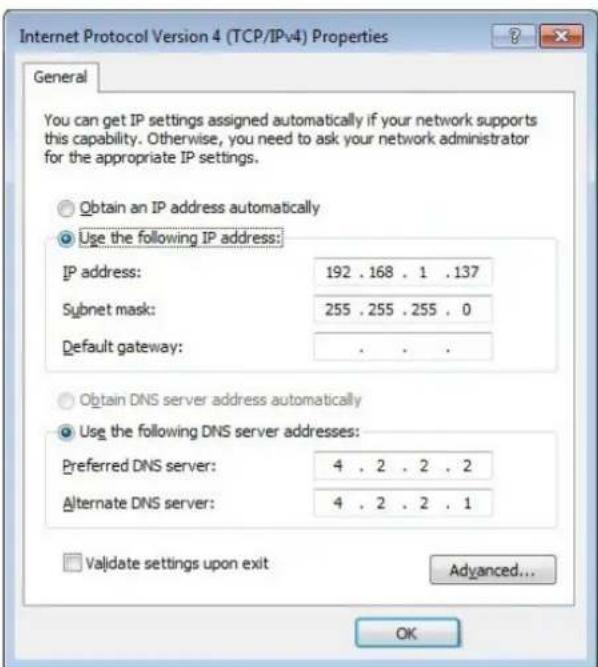
e) Click OK to save the configurations.
TheoperationsintheWindowsXPoperatingsystemareasfollows:
a) IntheWindowstaskbar, selectStart→ControlPanel. Double-click NetworkConnectiontoaccessthenetworkconnectionwindow.
b) Right-click Local Connection and select Properties from the shortcut menutobringuptheLocalConnectionPropertiesdialogbox.
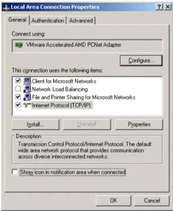
c) Double-click Internet Protocol (TCP/IP). In the Internet Protocol (TCP/IP) Properties dialog box that appears, set the IP address and subnet mask of the computer. Ford detail sof the parameters, see Table3-1.

d) ClickOKtosavetheconfigurations.
2.Enterhttp://192.168.1.1(defaultmanagementIPaddressoftheONT)inthebrowseraddressbarofthecomputer,andpresstheEnterkeytobringuptheuserlogindialogbox.
3.Entertheadministratorusernameandpasswordinthelogindialogbox.Access theWebGUIafterthepassworddisauthenticated.

Caution:
Thesystemwilllogoutautomaticallyifnouseroperationisdetectedin fiveminutes.
LayoutoftheWebConfigurationGUI
TheWebconfigurationGUIcomprisesthreeparts,asshowninFigure3-1.
◆ Navigationbar.Clickthelinktoaccessthecorrespondingconfiguration managementpage.
◆ Linkbar.Clickthelinktoaccessthesub-pageforcorrespondingconfiguration management.
◆Configurationmanagementarea.Displaystheitemsselectedinthenavigation barandlinkbar.

(1)Navigationbar(2)Linkbar(3)Configuration
managementarea
Figure3-1WebConfigurationGUI

Note:
Thescreenshotsprovidedhereareforreferenceonly,andtheactual WebGUIsfortheequipmentshallprevail.
The configuration GUIsfortheadadministratoraredifferentfromthoseforcommon users:
◆The administratorcanviewandconfigureallthenodeitemsintheWebGUI.
◆Thecommonuserscanviewandconfigureonlypartofthenodeitems.The followingliststhekeynodesavailableforcommonusers.Fordetailsofthe configurationitems,pleaserefertothepracticalGUIs.
TheStatustab.
▶ WlanSettingsintheNetworktab.
▶ User Account and Device Reboot in the Management tab.
3.2Status
ThissectionintroduceshowtoviewbasicinformationabouttheONT,includingthe deviceinformation,WANsidestatus,LANsidestatus,opticalpowerstatus,voice statusandwirelessnetworkstatus,etc.
3.2.1 DeviceInformation
Select Status in the navigation bar, and then select Device Information→Device Informationintheleftlinkbartoviewtheinformationsuchasthesoftwareversion, hardwareversion,devicemodelanddevicedescription,asshowninFigure3-2.
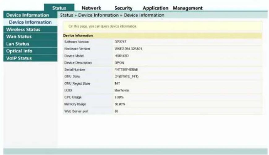
Figure3-2DeviceInformation
3.2.2 Wireless Network Status
Viewtheinformationaboutthewirelessnetwork,suchasnetworkmode,frequency channel,SSID,countofwirelesspackets,andlistofWi-Ficlients.
3.2.2.1 Wireless Network Status
Select Status in the navigation bar, and then select Wireless Status→Wireless Statusintheleftlinkbartoviewtheinformationofthewirelessnetwork,suchas networkmode,band,SSIDandwirelesspacketstatistics,asshowninFigure3-3.
Status » Wireless Status » Wireless Status
On this page, you can query state of wireless.
Wireless State
| Radio On/Off | radio on | ||
| Network Mode | 802.11 b/g/n | ||
| Frequency (Channel) | channel 9 | ||
| SSID1 Name | fat_111 | 34:bf:90:74:49:68 | Enable |
| SSID2 Name | HOMEFIBR44968_ssid2 | 72:bf:90:74:49:69 | Disable |
| SSID3 Name | HOMEFIBR44968_ssid3 | 72:bf:90:74:49:6a | Disable |
| SSID4 Name | HOMEFIBR44968_ssid4 | 72:bf:90:74:49:6b | Disable |
Wireless Packets Count
| Received Packets Count | 0 |
| Received Bytes Count | 0 |
| Error Received Packets Count | 0 |
| Loss Received Packets Count | 0 |
| Sent Packets Count | 0 |
| Sent Bytes Count | 0 |
| Error Sent Packets Count | 0 |
| Loss Sent Packets Count | 0 |
Figure3-3WirelessNetworkStatus
3.2.2.2Statusofthe5GWirelessNetwork
Select Status in the navigation bar, and then select Wireless Status→5G Wireless Statusintheleftlinkbartoviewtheinformationofthe5Gwirelessnetwork,suchas networkmode,band,SSIDandwirelesspacketstatistics,asshowninFigure3-4.
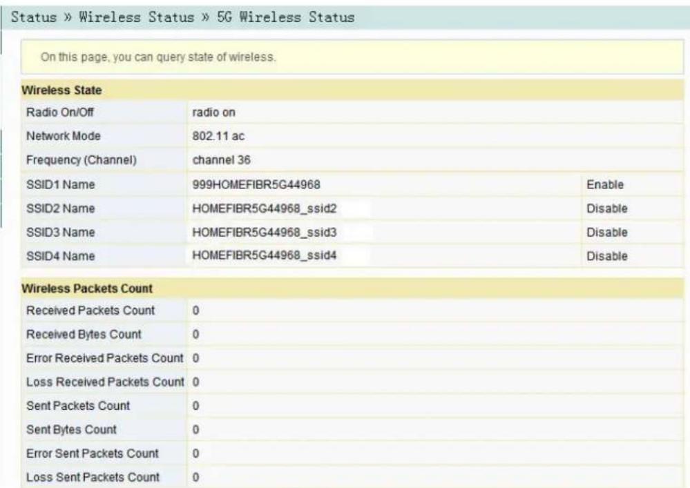
Figure3-4Statusofthe5GWirelessNetwork
3.2.2.3Wi-FiUserList
Select Status in the navigation bar, and then select Wireless Status→WIFI Clients ListintheleftlinkbartoviewthelistofclientendsconnectedtotheONTwireless network,asshowninFigure3-5.

Figure3-5WIFIUserList
3.2.3WANSideStatus
Select Status in the navigation bar, and then select Wan Status→Wan Status in the left linkbart view the informations such as the status, IP obtaining mode, IP address and subnet mask of the WAN interface, as shown in Figure 3-6.
| WAN State | ||||||||
| Index | State | Mode | IP Type | IP | Mask | DNS | VLAN/Priority | Connection Type |
| 1 | Up | INTERNET | 501/0 | Bridge | ||||
| 2 | Down | INTERNET | DHCP | 300/0 | Route | |||
Figure3-6WANSideStatus
3.2.4 LANSideStatus
CheckthestateinformationabouttheLANinterfaceandtheDHCPclientend.
3.2.4.1 LANSideStatus
Select Status in the navigation bar and select Lan Status→Lan Status in the left linkbartoviewtheinformationsuchastheIPaddressandsubnetmaskoftheLAN side,asshowninFigure3-7.
| On this page, you can query the state of LAN interface. | |
| LAN State | |
| IP Address | 192.168.1.1 |
| LAN Mask | 255.255.255.0 |
Figure3-7LANSideStatus
3.2.4.2DHCPUserList
Select Status in the navigation bar and select Lan Status→DHCP Clients List in the left linkbart view the information about the DHCP client ends such as the IP address, MAC address and leasetime, as shown in Figure 3-8.

Figure3-8DHCPUUserList
3.2.5OpticalPowerStatus
Select Status in the navigation bar and select Optical Info→Optical Info in the left linkbartoviewtheopticalmoduleinformationsuchastheTxopticalpower,Rx opticalpowerandworkingtemperature,asshowninFigure3-9.

Figure3-9OpticalPowerStatus
3.2.6VoiceStatus
Select Status in the navigation bar and select VoIP Status→VoIP Status in the left linkbartoviewtheinformationsuchastheportstatusandtelephonenumber,as showninFigure3-10.

Figure3-10VoiceStatus
3.3Network
ThissectionintroduceshowtomaketheWLAN, LAN, broadband, DHCPserver, authentication, IPv6andvoiceconfigurationsintheWebGUI.
3.3.1WLANSettings
ThissectionintroduceshowtoconfigureWi-FicontrolandWPSaswellasbasic andadvancedparametersofthewirelessnetworkontheWebpage.
3.3.1.1 BasicParameters
Configure the parameters of the 2.4G wireless networks such as the switch, network mode, domain, frequency bandwidth and frequency channel.
- Select Network in the navigation bar and select Wlan Settings→Basic in the leftlinkbartoopenthebasicsettingpageforthe2.4Gwirelessaccessservice, asshowninFigure3-11.
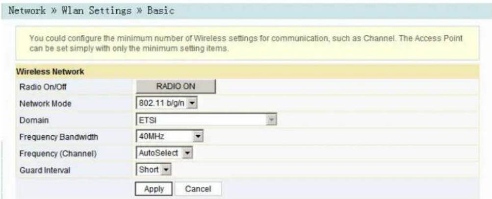
Figure3-11BasicParametersoftheWirelessNetwork
- Configurethebasicparametersofthe2.4Gwirelessnetwork.Fordetailsofthe parameters,seeTable3-2.
- ClickApplytosaveandapplytheconfiguration.
Table3-2BasicParametersofthe2.4GWirelessNetwork
| Item | Description |
| RadioON/OFF | EnablesordisabletheWLANservice.RADIOON:thewirelessnetworkis enabled;RADIOOFF:thewirelessnetworkisdisabled. |
| NetworkMode | Themodesupportedbythewirelessnetwork.Theoptionsinclude802.11b, 802.11g,802.11b/g,802.11nand802.11b/g/n.Thedefaultsettingis802.11b/g/n. |
| Domain | Selectyourregion. |
| Frequency Bandwidth | Thewidthofwirelessband.Theoptionsinclude20MHz/40MHz,20MHz and40MHz. |
| Frequency (Channel) | Thechannelusedforcommunicationbetweenthewirelessaccesspoint andthewirelessstation.TheoptionsincludesAutoSelectandChannel1 toChannel13.ThedefaultsettingisAutoSelect. |
| GuardInterval | The wireless protection interval. The options includeShortandLong. The defaultsettingisShort. |
3.3.1.2 AdvancedConfiguration
Configure the parameters of the 2.4G wireless network, such as the SSID, password, security mode and algorithm.
- Select Network in the navigation bar, and then select Wlan Settings → Advancedintheleftlinkbartoopentheadadvancedsettingpageforthe2.4G wirelessaccessservice,asshowninFigure3-12.

Figure3-12AdvancedSettingsoftheWirelessNetwork
-
Configuretheparametersofthe2.4Gwirelessnetwork,suchastheSSID, password,securitymodeandalgorithm.Fordetailsoftheparameters,see Table3-3.
-
ClickApplytosaveandapplytheconfiguration.
Table3-3AdvancedSettingParametersofWirelessNetwork
| Item | Description | |
| SSIDChoice | SelecttheSSID.Thevaluerangeis1to4. | |
| Enable/Disable | EnablesordisablesthecorrespondingSSID. | |
| SSIDName | Thewirelessnetworkname,usedtoidentifydifferentwirelessnetworks. | |
| Hidden | SelectwhethertohidetheSSID.WhentheSSIDishidden,thewireless terminalcannotdetectthewirelesssignalsunlesstheSSIDisentered. | |
| SecurityMode | Theauthenticationmodeforthewirelessterminalrequiringaccesstothe wirelessnetwork.TheoptionsincludeOPEN,SHARED,WEPAUTO,WPA-PSK,WPA2-PSKandWPAPSKWPA2PSK.◆OPEN:Unencrypted.Anyterminalcanaccessthewirelessnetwork;therefore,thesecuritycannotbeguaranteed.Thismodeisnot advisable.◆SHARED:ThismodeisbasedontheWEPencryptionprotocol,where thesamekeyisconfiguredforthewirelessaccessclientend and equipmentsidetoprovidethesamesecuritylevelasthewiredLAN.Itis atraditionalWLANsecurityprotocol.◆WEPAUTO:BothOPENWEPandSHAREDWEParesupported.◆WPA-PSK:ThismodeisbasedontheWLANsecurityprotocol,where a keyispre-configuredforthewirelessaccessclientend.Theequipment sideauthenticatesthelegalityofthewirelessaccessclientendkeyby the4-wayhandshakekeyagreementprotocol.Thisprovidesasaferand moreconfidentialwirelessnetworkservicethanWEP.◆WPA2-PSK:WPA2isthesecondeditionofWPA.◆WPAPSKWPA2PSK:theauthenticationmodecombiningWPAand WPA2. | |
| WPA Algorithms | TheencryptionalgorithmsincludeTKIP,AESand TKIPAES. | Thisitemshouldbe configuredifthe authenticationmode isWPA-PSK,WPA2-PSKor WPAPSKW-PA2PSK. |
| PassPhrase | EntertheSSIDkey. | |
| EncryptType | SelecttoenableordisabletheWEPencryptionwhenthenetwork authenticationmodeisOPEN. | |
| DefaultKey | SelectKey1toKey4;thatis,selectoneofthefour configurednetworkkeys. | Thisitemshouldbe configuredwhenthe authenticationmode isOPENandthe WEPencryptionis enabledorthe authenticationmode isSHAREDor WEPAUTO. |
| WEPKey1to WEPKey4 | Enterthekeyvalueandselectthekeyvaluetype.At leastentertheitemselectedinDefaultKey.◆IfASCIIisselected,youshouldenterakeyvalue containing5to13characters.◆IfHexisselected,youshouldentera hexadecimalfigurecontaining10to26 characters. | |

Note:
PressingtheApplybuttonwillvalidateasingleSSIDchoice
configurationitem.IfyoudonotclickApplyaftermodifyingtheSSID1
setting, themodificationwillnottakeeffect.
If the SSID1 setting is modified, the factory default wireless network account will be invalid.
If you forget the customized wireless network account, restore the factory default account by pressing down the Reset button form more than 5 seconds.
3.3.1.3Wi-FiControl
Configureparametersofthe2.4Gwirelessnetwork,suchasWi-Fipowerand numberofWIFIconnections.
- Select Network in the navigation bar, and then select Wlan Settings→WIFI ControlintheleftlinkbartoopentheWIFIcontrolsettingpageforthe2.4G wirelessaccessservice,asshowninFigure3-13.

Figure3-13WIFIControl
- Configureparametersofthe2.4Gwirelessnetwork, suchasWIFIpowerand numberofWIFIconnections. Fordetailsoftheparameters, seeTable3-4.
- ClickApplytosaveandapplytheconfiguration.
Table3-4ParametersofWIFIControl
| Item | Description |
| WIFIPowerControl | Thetransmitpowerofthewirelesssignal.Alargervalue indicatesawidersignalcoverage. |
| NumberofWIFI Connections | ThemaximumnumberofclientendssupportedbytheSSIDs. |
3.3.1.45GBasicParameters
Configure the parameters of the 5G wireless networks such as the switch, network mode, domain, frequency bandwidth and frequency channel.
- Select Network in the navigation bar and select Wlan Settings→5G Basic in the left link bartoopenthe basic setting page for the 5G wireless access service, as shown in Figure 3-14.

Figure3-14BasicParametersofthe5GWirelessNetwork
- Configurethebasicparametersofthe5Gwirelessnetwork.Fordetailsofthe parameters,seeTable3-5.
- ClickApplytosaveandapplytheconfiguration.
Table3-5BasicParametersofthe5GWirelessNetwork
| Item | Description |
| RadioON/OFF | EnablesordisabletheWLANservice.RADIOON:thewirelessnetworkis enabled;RADIOOFF:thewirelessnetworkisdisabled. |
| NetworkMode | Themodesupportedbythewirelessnetwork.Theoptionsinclude802.11a, 802.11a/nand802.11a/n/ac.Thedefaultsettingis802.11a/n/ac. |
| Domain | Selectyourregion. |
| Frequency Bandwidth | Thewidthofwirelessband.Theoptionsinclude20MHz/40MHz,20MHz, 40MHzand80MHz.Thedefaultsettingis80MHz. |
| Frequency (Channel) | Thechannelusedforcommunicationbetweenthewirelessaccesspoint andthewirelessstation.ThedefaultsettingisAutoSelect. |
| GuardInterval | The wireless protection interval. The options includeShortandLong. The defaultsettingisShort. |
3.3.1.55GAdvancedConfiguration
Configure the parameters of the 5G wireless network, such as the SSID, password, security mode and algorithm.
- Select Network in the navigation bar and select Wlan Settings→5G Advancedintheleftlinkbartoopentheadadvancedsettingpageforthe5G wirelessaccessservice,asshowninFigure3-15.

Figure3-15AdvancedSettingsofthe5GWirelessNetwork
- Configuretheparametersofthe5Gwirelessnetwork,suchastheSSID, password,securitymodeandalgorithm.Fordetailsoftheparameters,see Table3-3.
- ClickApplytosaveandapplytheconfiguration.

Note:
PressingtheApplybuttonwillvalidateasingleSSIDchoice configurationitem.IfyoudonotclickApplyaftermodifyingtheSSID1 setting,themodificationwillnottakeeffect.
If theSSID1 setting is modified, the factory default wireless network account will be invalid.
If you forget the customized wireless network account, restore the factory default account by pressing down the Reset button more than 5 seconds.
3.3.1.65GWi-FiControl
Configureparametersofthe5Gwirelessnetwork,suchasWi-Fipowerandnumber ofWIFIconnections.
- Select Network in the navigation bar and select Wlan Settings→5G WIFI ControlintheleftlinkbartoopentheWIFIcontrolsettingpageforthe5G wirelessaccessservice,asshowninFigure3-16.
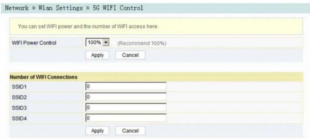
Figure3-165GWi-FiControl
- Configuretheparametersofthe5Gwirelessnetwork,suchasWIFIpowerand quantityofconnectedclientends.Fordetailsoftheparameters,seeTable3-4.
- ClickApplytosaveandapplytheconfiguration.
3.3.1.7WPSSConfiguration
WPScana utomaticallysetthewi relessnetworkname( SSID)andwireless encryptionkeyfor theHG61 43Dandcl ientendsup portingthe Wi-Fiserv ice.You need onlytopres sdownthe WPSbutto norentert hePINtoa chievesafe connection.Sinc eyouneed notremem berthelong encryption key,youa refreeof thetroublecause dbyforget tingthepas sword.
- SelectNetworkinthe navigation barandsel ectWlan Settings→WPS inthe leftlinkbartoopentheWPSsettingspage,asshowninFigure3-17.
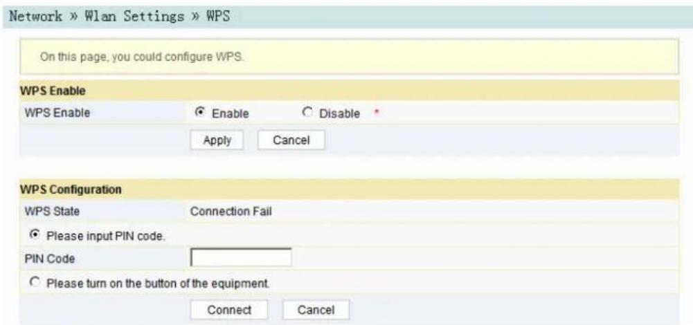
Figure3-17WPSSConfiguration
- SelectwhethertoenabletheWPSfunction. TheoptionsincludeEnableandDisable.
- SelecttheWPSconnectionmodeasrequired.
Select Please input PIN code., and enter the PIN code of the client end in thePINtextbox.ThenclickConnect.
Select Please turn on the button of the equipment and press down the WPSbuttonontheONT.ThenpressdowntheWPSbuttonontheWPS softwarekeyontheclientend.
- Wait until the connection is completed.
3.3.2 LAN Settings
ConfigurethemangementIPaddressandsubnetmaskattheLANside.
- Select Network in the navigation bar and select LAN Settings→LAN Settings intheleftlinkbartoopentheLANsettingspage,asshowninFigure3-18.

Figure3-18LANSettings
- ConfigurethemanagementIPaddressandsubnetmaskattheLANside. For detailsoftheparameters, seeTable3-6.
- ClickApplytosaveandapplytheconfiguration.
Table3-6ParametersofLANSettings
| ItemDescription | |
| GatewayIPAddress | ThemanagementIPaddressattheLANsideoftheONT.Thedefault settingis192.168.1.1. |
| SubnetMask | ThesubnetmaskoftheONTfortheLAN.Thedefaultsettingis255.255.255.0. |
| IPv6/Prefix | TheIPv6gatewayaddress,includingaprefixof64bits.Thedefault valueisfe80::1/64. |
| ManagedFlag | SelectwhethertodistributetheIPv6addressesbasedonDHCP.The defaultsettingisDisable. |
| OtherConfigFlag | SelectwhethertodistributetheIPv6DNSinformationbasedon DHCP.ThedefaultsettingisEnable. |
| MaxRAinterval | Themaximumintervalforannouncingthegatewayinformation.The defaultvalueis10. |
| MinRAinterval | Theminimumintervalforannouncingthegatewayinformation.The defaultvalueis5. |
| DNSSource | ThesourceoftheDNSdistributedtothePC.TheoptionsincludeWANconnection,ONTproxyandstaticconfiguration.ThedefaultsettingisWANconnection. |
| PrefixMode | ThesourceoftheprefixinformationdistributedtothePC.TheoptionsincludeWANconnectionandstaticconfiguration.ThedefaultsettingisWANconnection. |
| EnableDHCP6S | SetswhethertoenabletheDHCPv6server.ThisitemshouldbeselectedifManagedFlagorOtherConfigFlagisselected;otherwisetheIPaddressorDNSinformationcannotbedistributed.Theserverisenabledbydefault. |
| StartIPv6Address | ThestartingaddressIDoftheaddresspoolfordistributionofDHCPv6IPaddresses.Thedefaultvalueis0:0:0:2. |
| EndIPv6Address | TheendingaddressIDoftheaddresspoolfordistributionofDHCPv6IPaddresses.Thedefaultvalueis0:0:0:255. |
3.3.3 Broadband Settings
SelecttheWANconnectionsuitableforthenetworkenvironment,orconfigurethe parametersconcernedfortheselectedWANconnection.
- Select Network in the navigation bar and select BroadBand Settings→InternetSettingsintheleftlinkbartoopentheInternetsettingspage,as showninFigure3-19.
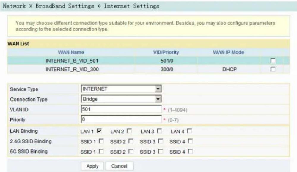
Figure3-19InternetSettings
- ConfigureparametersrelevanttotheInternetattheWANside.Fordetailsof theparameters,seeTable3-7.
- ClickApplytosaveandapplytheconfiguration.
Table3-7ParametersforInternetSettings
| Item | Description |
| ServiceType | Selectthese rvicetypeattheWANport.◆INTERNET:t hisconnectionisonlyapp licableforInternetaccess.◆VOIP:thiscon nnectionisonlyapplicable forvoiceapplication.◆VOIP_ INTERNET:thisconnectio nisapplicableforvoicean dInternet access.◆ OTHER:otherconnections. |
| Connection Type | SelecttheconnectiontypeoftheWANport.◆Bridge:theLayer2bridgeconnectionmode.Thisconnectionmodecan beusedwhentheservicetypeissettoINTERNETorOTHER.◆Route:theLayer3routerconnectionmode.Thisconnectionmodecan beusedwhentheservicetypeissettoINTERNETorOTHER. |
| VLANID | SetstheVLANIDoftheWANconnection.Thevaluerangeis1to4094.TheVLANIDvaluehereshouldbeconsistentwiththatontheusersideofthe OLT. |
Table3-7 Parameters for Internet Settings(Continued)
| Item | Description | |
| PrioritySetsthe priorityoftheVLAN.Thevaluerangeis0to7. | ||
| NATEnablesord isablestheNATfunction. | ◆UsersneedtoconfigurethisitemwhentheservicetypeissettOTOIP_INTERNET.◆UsersneedtoconfigurethisitemwhentheservicetypeissettolINTERNETorOTHERandtheconnectiontypeissettoRoute. | |
| DNSRelayEnablesordisablestheDNSrelayfunction. | ||
| MTU | Enterthemaximumtransmissionunit.Itisadvisedtousethedefaultvalue. | |
| LANBindingSelecttheLANporttobeboundwiththeWANport. | ||
| 2.4GSSIDBinding | Selectthewireless2.4GSSIDtobeboundwiththeWANport. | |
| 5GSSIDBinding | Selectthewireless5GSSIDtobeboundwiththeWANport. | |
| IPMode | TheoptionsincludeIPv4&IPv6,IPv4andIPv6. | ◆Usersneedtoconfigurethis itemwhentheserv icetypeissettOTOIP_INTERNET.◆Usersneedtoconfigurethis itemwhentheserv icetypeissettolINTERNETorOTHERandtheconnectiontypeiss ettoRoute. |
| WANIPMode | SetstheIPaddressobtainingmodeattheWANsideoftheONT.TheoptionsincludeDHCP,staticandPPPoE.◆DHCP:ObtainingtheIPaddressdynamically.◆Static:SettingtheIPaddressinastaticmode.◆PPPoE:PPPoEdialingmode. | ThisitemshouldbesetiftheconnectiontypeisRoute. |
| UserName | EntertheusernameprovidedbytheISP. | Thisitemshouldbesetif theWANIPModeissetto PPPoE. |
| Password | EnterthepasswordprovidedbytheISP. | |
| Operation Mode | SetsthePPPoEconnectionmode.Thedefault settingisKeepAlive. | |
| IPAddress | EnterthestaticIPaddressattheWANside providedbytheISP. | Thisitemshouldbeset whentheIPModeissetto IPv4&IPv6orIPv4andthe WANIPModeissetto static. |
| Netmask | EnterthesubnetmaskprovidedbytheISP. | |
| Default Gateway | EnterthedefaultgatewayprovidedbytheISP. | |
| PrimaryDNS Server | EntertheIPaddressoftheactiveDNSserver providedbytheISP. | |
| Secondary DNSServer | EntertheIPaddressofthestandbyDNS serverprovidedbytheISP. | |
| IPv6Address | EnterthestaticIPv6addressattheWANside providedbytheISP. | Thisitemshouldbeset whentheIPModeissetto IPv4&IPv6orIPv6andthe WANIPModeissetto static. |
| IPv6Prefix Length | EnterthestaticIPv6addressprefixlengthat theWANsideprovidedbytheISP. | |
| Default Gateway | EnterthedefaultgatewayprovidedbytheISP. | |
| PrimaryDNS Server | EntertheIPaddressoftheactiveDNSserver providedbytheISP. | |
| Secondary DNSServer | EntertheIPaddressofthestandbyDNS serverprovidedbytheISP. | |
| IPv6Address Mode/IPv6 PrefixMode | SelecttheIPv6addressobtainingmode/ prefixobtainingmode. | Thisitemshouldbeset whentheIPModeissetto IPv4&IPv6orIPv6andthe WANIPModeissetto DHCPorPPPoE. |
3.3.4 DHCP Server
The DHCP function enables the ONT to distribute network parameters (such as the IP address, gateway and DNS server IP address) to the devices (such as a computer) in the LAN. Users can manage the IP addresses collectively using this function.
- Select Network in the navigation bar, and then select DHCP Server→DHCP ServicefromtheleftlinkbartoopentheDHCPserverconfigurationpage, as showninFigure3-20.

Figure3-20DHCPService
- ConfiguretheDHCPserverparametersasrequired.Fordetailsofthe parameters,seeTable3-8.
- ClickApplytosavetheconfigurationinformation. The configuration will take effectaftertheONTisrebooted.
Table3-8ParametersfortheDHCPServer
| Item | Description | |
| Type | EnablesordisabletheDHCPserver.◆Server:EnabletheDHCPserver.TheONTcandynamically distributeIPaddressestouserterminals.◆Disable:TheuserterminalsconnectedtotheONTcannotobtainthe privatenetworkIPaddressusingtheDHCP. | |
| DHCPStartIP | ThestartingIPaddresssofthelPaddress poolfortheactiveDHCPserver. | Note:TheIPaddressset hereshouldbeinthe samenetworksegment withthelPaddresssetin LANSettings;otherwise, theDHCPserverwillnot operatenormally. |
| DHCPEndIP | TheendingIPaddresssofthelPaddress poolfortheactiveDHCPserver. | |
| DHCPSubnet Mask | ThemaskoftheactiveDHCPserver. | |
| DHCPPrimary DNS | TheIPaddressoftheactiveDNSserver. | |
| DHCPSecondary DNS | TheIPaddressofthestandbyDNSserver. | |
| DHCPDefault Gateway | ThedefaultgatewayoftheactiveDHCPserver. | |
| DHCPLease Time | TheleasetimeoftheIPaddresspooloftheDHCPserver. | |
| Option60SetswhethertoenabletheOption60propertytoidentifytheuserterminal. | ||
| Option60startIP | ThestartingIPaddressofthenetworksegmentdistributedtotheOption60propertyterminalbytheDHCPserver. | ThisitemshouldbeconfiguredwhentheOption60fieldoftheDHCPserverisenabled. |
| Option60endIP | TheendingIPaddressofthenetworksegmentdistributedtotheOption60propertyterminalbytheDHCPserver. | |
3.3.5 Authentication Settings
Configure the parameters relevant to the ONT authentication mode, so that the ONT can pass the OLT authentication.
- Select Network in the navigation bar and select Authentication→OLT AuthenticationintheleftlinkbartoopentheOLTauthenticationconfiguration page,asshowninFigure3-21.

Figure3-21OLTAuthentication
- Configuretheparametersasrequired.Fordetailsoftheparameters,see Table3-9.
- ClickApplytosavetheconfigurationinformation. The configuration will take effectaftertheONTisrebooted.
Table3-9ParametersforOLTAuthentication
| Item | Description | |
| LOIDSetstheLOIDusername. Thisitemisconfigurable | whentheONTusestheLOIDauthenticationmode. | |
| LogicPasswordSetstheLOIDpassword. | ||
| PasswordAuth | SetstheauthenticationpasswordwhentheONT isauthenticatedby password. | |
3.3.6 IPv6
ConfiguretheIPv6staticrouting.
- Select Network in the navigation bar. Select IPV6→IPV6 Static Route from the left link bar, and click Add in the information bar that appears at the right part to open the page for configuring the IPv6 static routing table, as shown in Figure 3-22.
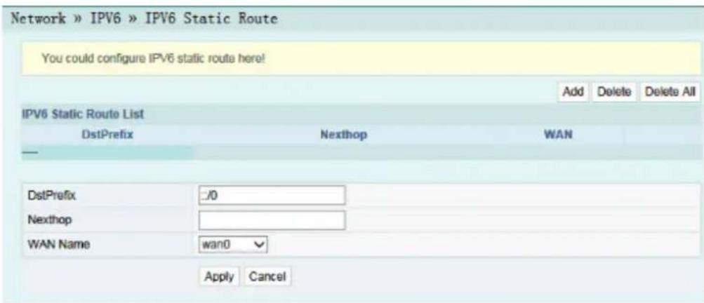
Figure3-22|Pv6StaticRouting
- Configuretheparametersrelevanttostaticroutingasrequired.Fordetailsof theparameters,seeTable3-10.
- ClickApplytosaveandapplytheconfiguration.
Table3-10ParametersfortheIPv6StaticRouting
| ItemDescription | |
| DstPrefix | ThedestinationIPaddressstobeaccessedbythehost. |
| NexthopTheIPaddress | softhenext-hopgateway. |
| WANName | TheWANportpassedbythestaticrouting.SelectavalidWANport. |
3.3.7 VoiceConfiguration
Thissectionintroduceshowtoconfigurethekeyparameters,basicparameters,advancedsettings,digitmapandtimelength,andcodingmodeforvoiceservicesintheWebpage.
3.3.7.1 KeyParameters
Configure the parameters such as VoIP protocol type and VoIP port.
- Select Network in the navigation bar and select VoIP Settings→Key ParametersfromthelinkbarontheleftsidetoopentheVoIPkeyparameter page,asshowninFigure3-23.

Figure3-23KeyParametersforVoiceConfiguration
- ConfigurethekeyVolPparametersasrequired.Fordetailsoftheparameters, seeTable3-11.
- ClickApplytosaveandapplytheconfiguration.
Table3-11KeyParametersforVoiceService
| Item | Description |
| VoIPProtocol | Thevoiceprotocoltype.TheoptionsincludeSIPandH.248.Thedefault settingisSIP. |
| Port | EnableordisabletheVoIPport. |
3.3.7.2 Basic Parameters
Configurebasicvoiceparameters.
- Select Network in the navigation bar and select VoIP Settings→Basic from thelinkbarontheleftsidetoopentheVoIPbasicparameterconfigurationpage, asshowninFigure3-24.

Figure3-24BasicParametersforVoiceConfiguration
- ConfigurethebasicVoIPparametersasrequired.Fordetailsoftheparameters, seeTable3-12.
- ClickApplytosaveandapplytheconfiguration.
Table3-12BasicParametersforVoiceService
| Item | Description | |
| VolPProtocol | TheVolPprotocoltype,configuredinKeyParameters. | |
| VolPUsernameTheVolPusername. | ||
| VolPPassword | TheVolPpassword. | |
| TelephoneNumberThetelephonenumberforthevoiceport. | ||
| FirstRegisterServer | TheIPaddressordomainnameoftheactiveregisterserver.Theport numberrangeis1024to65535,andthedefaultsettingis5060. | |
| SecondRegister Server | TheIPaddressordomainnameofthestandbyregisterserver.The portnumberrangeis1024to65535,andthedefaultsettingis5060. | |
| FirstProxyServer | TheIPaddressordomainnameoftheactiveproxyserver.Theport numberrangeis1024to65535,andthedefaultsettingis5060. | |
| SecondProxyServer | TheIPaddressordomainnameofthestandbyproxyserver.Theport numberrangeis1024to65535,andthedefaultsettingis5060. | |
| FirstDNSAddressTheactiveDNSaddress. | ||
| SecondDNSAddress | ThestandbyDNSaddress. | |
| CVLANID | TheCVLANID.Thevaluerangeis1to4095. | |
| CVLANPriority | TheCVLANpriority.Thevaluerangeis0to7,andthedefaultsetting is0. | |
| SVLANID | TheSVLANID.Thevaluerangeis1to4095. | |
| SVLANPriority | TheSVLANpriority.Thevaluerangeis0to7,andthedefaultsetting is0. | |
| IPMode | ThewaytoobtainIPaddress.TheoptionsincludeSTATIC,DHCP andPPPoE. | |
| IPTheIPaddress. | Thisitemshouldbe configurediftheIPMode issettoSTATIC. | |
| NetmaskThesubnetmask. | ||
| GatewayThegateway. | ||
| PPPoEUsernameThePPPoEusername.Thisitemshouldbe | configurediftheIPMode issettoPPPoE. | |
| PPPoEPassword | ThePPPoEpassword. | |
3.3.7.3 AdvancedConfiguration
ConfigureadvancedVoIPparameters.
- Select Network in the navigation bar and select VoIP Settings→Advanced in the left link bartoopenthead advanced VoIP setting page, as shown in Figure 3-25.
Configurecodingpriorityforvoiceports. The parameters include priority, coding mode, RTPpacketization period, and soon.
- Select Network in the navigation bar and select VoIP Settings→Coding from thelinkbarontheleftsidetoopenthecodingconfigurationpage,asshownin Figure3-27.

Figure3-27Coding
- Configureparametersofvoiceports, includingpriority,codingmodeandRTP packetizationperiod,asshowninTable3-15.
- ClickApplytosaveandapplytheconfiguration.
Table3-15CodingParameters
| Item | Description |
| Mode | Thecodingmode.TheoptionsincludeG.711MuLaw,G.711ALaw,G.723.1,G.729andG.722. |
| Packetization Period | TheRTPpacketizationperiod.Thevaluerangeis10to60(ms). |
3.4 Security
Thissectionintroduceshowtoconfigurethefirewall,remotecontrol,routeQoS, ACLconfiguration,dynamicDoSandHTTPSintheWebGUI.
3.4.1 Firewall
Thefirewallconfigurationincludes
◆FirewallControl
◆IPv4Filtering
◆IPv6Filtering
◆URLFiltering
◆DHCPFiltering
◆Anti-portScan
◆ MACFiltering
◆IPv6MACFiltering
3.4.1.1 FirewallControl
Enabling the firewall can prevent malicious access to the WAN port of the ONT.
- Select Security in the navigation bar and select Firewall→Firewall Control in the left link bartoopenthe firewallenabling page, asshownin Figure 3-28.

Figure3-28FirewallControl
- SelecttoEnableorDisablethefirewallasrequired.
- ClickApplytosaveandapplytheconfiguration.
AlloworforbidtheincomingoroutgoingflowoftheIPpacketsmeetingthefiltering criteria. Afterthefirewallisenabled, thepre-setruleswilltakeeffect.
- Select Security in the navigation bar and select Firewall→IPv4 Filtering in the leftlinkbar.ThenclickAddtoopenthefilteringrulelistconfigurationpage,as showninFigure3-29.
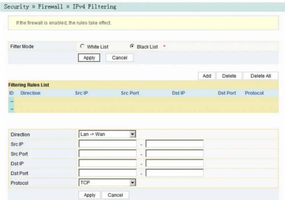
Figure3-29IPv4Filtering
- Configuretheparametersrelevanttofilteringasrequired.Fordetailsofthe parameters,seeTable3-16.
- ClickApplytosaveandapplytheconfiguration.
Table3-16ParametersforIPAddressFiltering
| Item | Description | |
| FilterMode | Selectthefilteringmode.◆WhiteListindicatesthatthedatacomplyingwiththerulesinthefilteringruletablewillbeallowedtopass.◆BlackListindicatesthatthedatacomplyingwiththerulesinthefilteringruletablewillnotbeallowedtopass. | ClicktheApplybuttonbelowtoapplythesettings. |
| Direction | Setsthedirectionofthefilteringrule.◆LAN->WAN:uplinkdirection.◆WAN->LAN:downlinkdirection. | |
| SrcIP | EntertheIPaddressattheLANsideifthedirectionisLAN->WAN.EntertheIPaddressattheWANsideifthedirectionisWAN->LAN. | |
| SrcPort | TheportrangeofthesourceIPaddress.ThisitemisconfigurablewhentheProtocolissettoTCPorUDP. | |
| DstIP | EntertheIPaddressattheWANsideifthedirectionisLAN->WAN.EntertheIPaddressattheLANsideifthedirectionisWAN->LAN. | |
| DstPort | TheportrangeofthedestinationIPaddress.Thisitemisconfigurablewhen theProtocolissettoTCPorUDP. | |
| Protocol | Theprotocoltype,includingTCP,UDP,ICMPandALL. | |
BysettingtheURLfilteringrules, userscanforbidorallowallthedatapacketssent toorreceivedfromacertainIPaddress. Afterthefirewallisenabled, thepre-set URLfilteringrulewilltakeeffect, andthedomainnamesthatmeetthefiltering criteriawillbefiltered.
- Select Security in the navigation bar and select Firewall→URL Filtering in the leftlinkbar, and then click Add to open the URL filtering table configuration page, as shown in Figure 3-31.
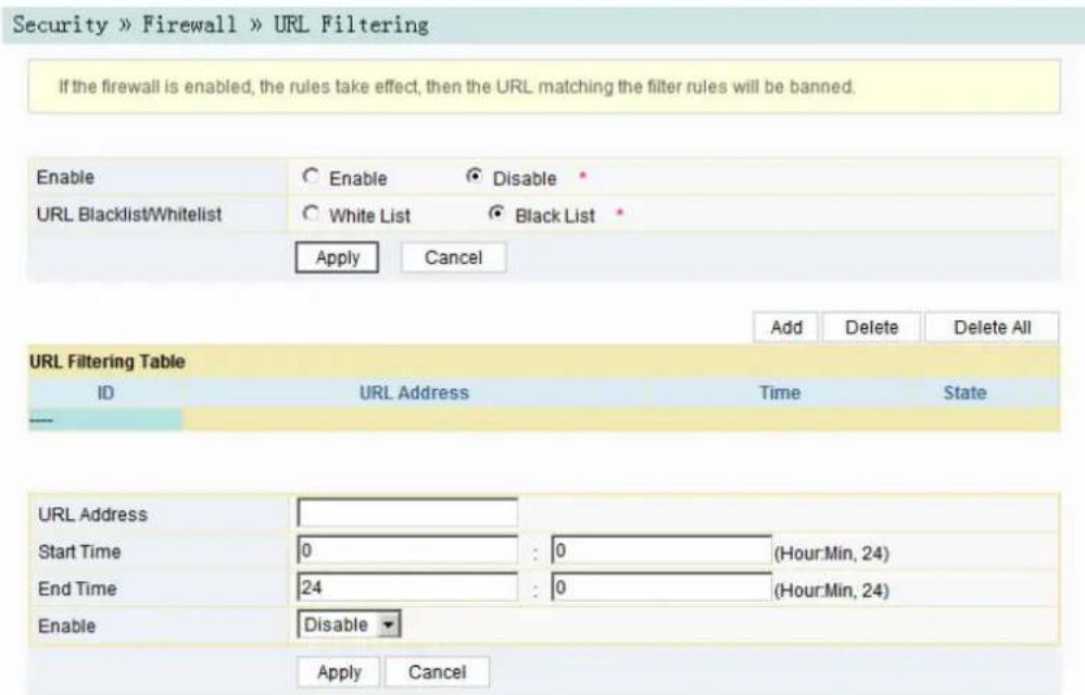
Figure3-31URLFiltering
- Configuretheparametersrelevanttofilteringasrequired.Fordetailsofthe parameters,seeTable3-18.
- ClickApplytosaveandapplytheconfiguration.
Table3-18ParametersforURLFilteringParameters
| Item | Description | |
| Enable | EnablesordisablestheURLfilteringfunction. | ClicktheApplybuttonbelowtoapplythesettings. |
| URLBlacklist/Whitelist | Selectthefilteringmode.Thewhitelistandblacklistmodesareconfiguredgloballyandcannotbeenabledsimultaneously.◆WhiteListindicatesthatthedatacomplyingwiththerulesdefinedinthefilteringtablewillbeallowedtopass.◆BlackListindicatesthatthedatacomplyingwiththerulesdefinedinthefilteringtablewillnotbeallowedtopass. | |
| URLAddress | TheURLaddressaccessedbyusers. | |
| StartTime | Thestartingtimeofthefilteringrule. | |
| EndTime | Theendingtimeofthefilteringrule. | |
| Enable | Enablesordisablethisfilteringrule.TheoptionsincludeDisableand Enable. | |
3.4.1.5DHCPFiltering
ForbidorallowtheuserdeviceconfiguredwiththeMACaddressstoobtainanIP addressintheDHCPmodetopreventDOSattacks. Afterthefirewallisenabled, the pre-setruleswilltakeeffect.
- Select Security in the navigation bar and select Firewall→DHCP Filtering in the left link bar. Then click Add to open the DHCP Filtering Table configuration page, as shown in Figure 3-32.

Figure3-32DHCPFiltering
- Configuretheparametersrelevanttofilteringasrequired.Fordetailsofthe parameters,seeTable3-19.
- ClickApplytosaveandapplytheconfiguration.
Table3-19ParametersforDHCPFiltering
| Item | Description | |
| DHCPFiltering Enable | EnablesordisabletheDHCPfiltering. | ClicktheApplybuttonbelowtoapplythesettings. |
| DHCPFiltering Blacklist/Whitelist | Selectthefilteringmode.Thewhitelistandblacklist modesareconfiguredgloballyandcannotbeenabled simultaneously.◆WhiteListindicatesallowingthedevice configuredwiththeMACaddresstoobtainanIP addresssthroughtheDHCP.◆BlackListindicatesforbiddingthedevice configuredwiththeMACaddresstoobtainanIP addresssthroughtheDHCP. | |
| MACAddress | TheMACaddressoftheuserdevicesubjectttotheDHCPfilteringrule. | |
3.4.1.6 Anti-portScan
Enableordisabletheanti-portscanfunction.
- Select Security in the navigation bar and select Firewall→Anti Port Scan in the left link bartoopenthe anti-port scan page, asshownin Figure 3-33.

Figure3-33 Anti-port Scan
- Select to Enable or Disable the anti-port scan function as required.
- ClickApplytosaveandapplytheconfiguration.
3.4.1.7 MACAddressFiltering
OneuserdevicemayhavemultipleIPaddressesbutonlyoneMACaddress. The userdeviceaccessauthorityintheLANcanbecontrolledeffectivelybysetting the MACaddressfiltering. Afterthefirewallisenabled, thepre-setruleswilltakeeffect, andtheMACaddressesthatmeetthefilteringcriteriawillbefiltered.
- Select Security in the navigation bar and select Firewall→MAC Filtering in the left link bar, and then click Add to open the MAC address filtering table configuration page, as shown in Figure 3-34.

Figure3-34MACAddressFiltering
- Configureparametersrelevanttofilteringasrequired. Fordetailsofthe parameters, seeTable3-20.
- ClickApplytosaveandapplytheconfiguration.
Table3-20ParametersforMACAddressFiltering
| Item | Description | |
| MACFiltering Enable | EnablesordisablestheMACaddressfiltering function. | ClicktheApply buttonbelowtoapply thesettings. |
| MACFilteringBlacklist/Whitelist | Selectthefilteringmode.Thewhitelistandblacklistmodesareconfiguredgloballyandcannotbe enabledsimultaneously.◆WhiteListindicatesthatthedatacomplying withtherulesdefinedinthefilteringtablewill beallowedtopass.◆BlackListindicatesthatthedatacomplying withtherulesdefinedinthefilteringtablewill notbeallowedtopass. | |
| MACAddress | TheMACaddressintheMACaddressfilteringrule. | |
| StartTime | Thestartingtimeofthefilteringrule. | |
| EndTime | Theendingtimeofthefilteringrule. | |
| Enable | Enablesordisablethisfilteringrule.TheoptionsincludeDisableand Enable. | |
OneuserdevicemayhavemultipleIPv6addressesbutonlyoneMACaddress. The userdeviceaccessauthorityintheLANcanbecontrolledeffectivelybysettingthe MACaddressfiltering. Afterthefirewallisenabled, thepre-setruleswilltakeeffect, andtheMACaddressesthatmeetthefilteringcriteriawillbefiltered.
- Select Security in the navigation bar and select Firewall→IPv6 MAC Filtering intheleftlinkbar, and thenclick Addtoopentheconfigurationpageforthe MACaddressfilteringtable, asshowninFigure3-35.

Figure3-35|Pv6MACFiltering
- Configuretheparametersrelevanttofilteringasrequired.Fordetailsofthe parameters,seeTable3-21.
- ClickApplytosaveandapplytheconfiguration.
Table3-21ParametersforIPv6MACAddressFiltering
| Item | Description | |
| IPv6MAC FilteringEnable | EnablesordisablestheIPv6MACaddressfiltering function. | ClicktheApply buttonbelowto applythesettings. |
| IPv6MAC Filtering Blacklist/ Whitelist | Selectthefilteringmode.Thewhitelistandblacklist modesareconfiguredgloballyandcannotbeenabled simultaneously.◆WhiteListindicatesthatthedatacomplyingwith therulesdefinedinthefilteringtablewillbe allowedtopass.◆BlackListindicatesthatthedatacomplyingwith therulesdefinedinthefilteringtablewillnotbe allowedtopass. | |
| MACAddress | TheIPv6MACaddressintheIPv6MACaddress filteringrule. | |
| StartTime | Thestartingtimeofthefilteringrule. | |
| EndTime | Theendingtimeofthefilteringrule. | |
| Enable | Enablesordisablethisfilteringrule.TheoptionsincludeDisableandEnable. | |
3.4.2 RemoteControl
Enableordisabletheremoteaccesscontrol.Whetheremotecontrolisdisabled, thePCsintheInternetcannotaccesstheWebGUIoftheONTusingtheIP addressesattheWANside;whenenabled,thePCsintheInternetcanaccessthe WebGUIoftheONTusingtheaforesaidIPaddresses.
- Select Security in the navigation bar and select Remote Control→Remote Controlintheleftlinkbartoopentheremotecontrolconfigurationpage, as showninFigure3-36.

Figure3-36RemoteControl
- EnableorDisabletheremoteaccesscontrolasrequired.
- ClickApplytosaveandapplytheconfiguration.
3.4.5 DynamicDoS
TheDoSattackexhauststheresourceoftargetcomputerusingmassivevirtual informationflow,sothattheattackedcomputerhastohandlethevirtualinformation withallstrength,whichinfluencesthehandlingofnormalinformationflow.TheONT providestheprotectionagainsttheDoSattack.
- Select Security in the navigation bar and select DDOS→DDOS in the left link bartoopentheanti-DoSattackconfigurationpage,asshowninFigure3-41.
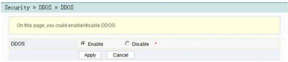
Figure3-41DynamicDoS
- Select to Enable or Disable the anti-dos attack function as required.
- ClickApplytosaveandapplytheconfiguration.
3.4.6 HTTPS
TheONTprovidestheHTTPSfunction.HTTPSistheHTTPchannelforsecurity purpose.ItisbuiltintheSSL+HTTPprotocol,andcanperformencryption transmissionandidentityauthentication.
- Select Security in the navigation bar and select HTTPS→HTTPS in the left link bartoopentheHTTPSfunctionconfigurationpage,asshowninFigure3-42.

Figure3-42HTTPS
- SelecttoEnableorDisabletheHTTPSfunctionasrequired.

Caution:
AfterenablingtheHTTPSfunction,logintotheWebGUI.Theprotocol typeinURLshouldbehttpsandthemanagementIPaddresssshouldbe addedwiththeportnumber4433,e.g.https://192.168.1.1:4433.
- ClickApplytosaveandapplytheconfiguration.
3.5Application
ThissectionintroduceshowtoconfiguretheVPN,DDNS,portforwarding,NAT,UPnP,DMZandnetworkdiagnosisontheWebGUI.
3.5.1VPN
SetwhethertoenabletheVPNtransparenttransmissionchannel.
- Select Application in the navigation bar and select VPN→VPN Pass-through intheleftlinkbartoopenthepageforconfiguringtheVPNtransparent transmission,asshowninFigure3-43.

Figure3-43VPNTransparentTransmission
- Select to Enable or Disable the VPN transparent transmission channel as required.
- ClickApplytosaveandapplytheconfiguration.
3.5.2DDNS
TheDDNSservertransformsthedynamicIPaddressattheWANsideoftheONT intoastaticdomainname.UsersfromInternetcaneasilyaccessthegatewayusing thisdomainname.
- Select Application in the navigation bar and select DDNS→DDNS in the left linkbartoopentheDDNSconfigurationpage,asshowninFigure3-44.

Figure3-44DDNSSettings
-
ConfigureparametersrelevanttoDDNSaccordingtotherequirement. For detailsoftheparameters, seeTable3-24.
-
ClickApplytosaveandapplytheconfiguration.
Table3-24ParametersforDDNSSettings
| Item | Description |
| Username | TheusernameallocatedbytheDDNSprovider. |
| Password | ThepasswordallocatedbytheDDNSprovider. |
| Host | ThedomainnameallocatedbytheDDNSprovider. |
| WANInterfaceThename | ofthecreatedWANconnection. |
| DDNSProvider | TheDDNSserviceprovider.UserscanselectthepresetDDNS providerorselectOthertocustomizetheproviderandsetthedomain name,serverIPaddress,protocoltypeandURL. |
3.5.3 PortForwarding
PortforwardingcangeneratethemappingbetweentheWANportIPaddress/commonportnumberandtheLANserverIPaddress/privateportnumber.Inthis way,alltheaccessestoacertainserviceportatthisWANportwillbere-directedto thecorrespondingportoftheserverinthedesignatedLAN.
- Select Application in the navigation bar and select Port Forwarding→Port Forwarding in the left link bar. Then click Add to open the port forwarding configurationpage,asshowninFigure3-45.
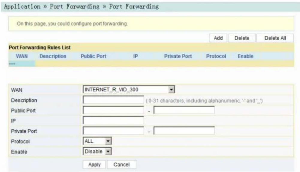
Figure3-45PortForwarding
- Configureparametersrelevanttoportforwardingaccordingtotherequirement. Fordetailsoftheparameters,seeTable3-25.
- ClickApplytosaveandapplytheconfiguration.
Table3-25ParametersforPortForwarding
| ItemDescription | |
| WAN | TheWANconnectionboundwiththeportforwardingrule. |
| DescriptionTheportforwardingrulename. | |
| PublicPort | Therangeofportsforextranetdatapackets.lfonlyoneportexists, enterthesameportnumber. |
| IP | TheIPaddressoftheLANvirtualserverforportforwarding. |
| PrivatePort | TherangeoftheLANportsforforwarding.Ifonlyoneportexists,enterthesameportnumber. |
| Protocol | Theprotocolusedfortheporttoforwarddatapackets.TheoptionsincludeALL,TCPandUDP. |
| EnableEnablesordisablestherule. | |
3.5.4NAT
NATallowstheconversionbetweenintranetIPaddressesandpublicnetworkIP addresses.NATconvertsagreatnumberofintranetIPaddressesintooneora smallnumberofpublicnetworkIPaddresses,soastosavetheresourceofpublic networkIPaddresses.
TheNATconfigurationbelowcantakeeffectonlywhentheNATfunction is enabled in Network→BroadBand Settings→Internet Settings.
- Select Application in the navigation bar and select NAT→NAT in the left link bar. ThenclickAddtoopentheNATrulelistconfigurationpage,asshownin Figure3-46.
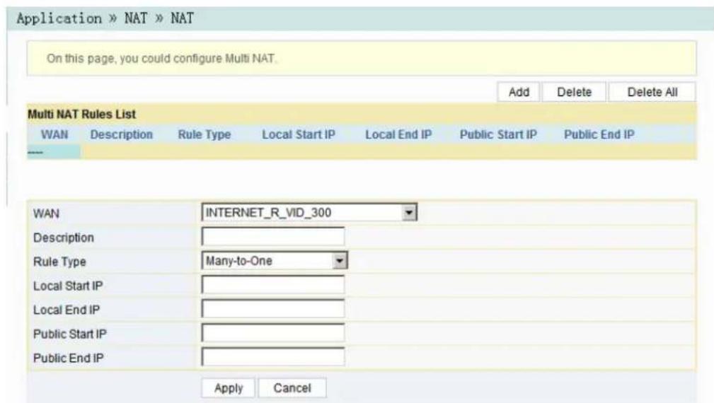
Figure3-46 NAT
- Configurerelevantparametersaccordingtotherequirement.Fordetailsofthe parameters,seeTable3-26.
- ClickApplytosaveandapplytheconfiguration.
Table3-26ParametersforNATConfiguration
| Item | Description |
| WANTheWANconnectionboundwiththeNATrule. | |
| Description | TheNATrulename. |
| RuleType | SelecttheNATconversionmode.ItisadvisabletoselectOne-to-OneorMany-to-One. |
| LocalStartIP | ThestartingIPaddressoftheintranet. |
| LocalEndIP | TheendingIPaddressoftheintranet. |
| PublicStartIP | ThestartingIPaddressofthepublicnetwork. |
| PublicEndIP | TheendingIPaddressofthepublicnetwork. |
3.5.6DMZ
When the ONT is working in the routing mode, enable the DMZ function if a host at the WAN sideneed to access a certain host at the LAN side. The ONT will forward all the IP packets from the WAN to the designated DMZ host.
- Select Application in the navigation bar and select DMZ→DMZ in the left link bartoopentheDMZconfigurationpage,asshowninFigure3-48.

Figure3-48DMZ
- Configurerelevantparametersaccordingtotherequirement.Fordetailsofthe parameters,seeTable3-27.
- ClickApplytosaveandapplytheconfiguration.
Table3-27ParametersforDMZConfiguration
| Item | Description |
| DMZEnable | EnablesordisablestheDMZfunction.TheoptionsincludeEnable,DisableandAuto.IfEnableis selected,the DMZ host IP address shouldbeset.IfAutoisselected,theDMZhostusesthefirstIPaddress allocatedbyDHCP. |
| DMZHostIPThehostIP | addresssoftheDMZ. |
3.5.7 NetworkDiagnosis
NetworkdiagnosisincludesnetworkdiagnosisandNatconversation.
3.5.7.1 Network Diagnosis
TheONTprovidestwonetworkdiagnosistools.
◆ Pingtest: Testwhethertherouterisnormallyconnectedwiththetargethostor anotherdevice.
◆ Traceroutetest: Checktheconditionoftheroutefromtheroutertothetarget host.
- Select Application in the navigation bar and select Diagnosis→Diagnosis in the left link bartoopenthenetworkdiagnosis page, asshownin Figure 3-49.
Application » Diagnosis » Diagnosis

Figure3-49NetworkDiagnosis
2.EnterthedestinationIPaddressstobetestedintheDestinationAddressbox, and click Ping or Traceroute to test. The test result will be displayed in the lowertextbox.
3.5.7.2NatSession
Click Application and select Diagnosis→Nat Session at the left side to open the Natsessionpageandquerythemappingsbetweentheinner/outernetworkIP addressofNATandtheports,asshowninFigure3-50.
![Application » Diagnosis » Nat Session You could view NAT IP and port mapping between inside and outside network on this page. NAT Session ipv4 2 udp 17 175 src=10.25.114.67 dst=10.25.100.18 sport=3011 dport=3011 src=10.25.100.18 dst=10.25.114.67 sport=3011 dport=3011 [ASSURED] mark=0 use=3 ipv4 2 icmp 1 2 src=192.168.1.1 dst=192.168.1.1 type=8 code=0 id=29769 src=192.168.1.1 dst=192.168.1.1 type=0 code=0 id=29769 mark=0 use=2 ipv4 2 tcp 6 299 ESTABLISHED src=192.168.1.147 dst=192.168.1.1 sport=54472 dport=80 src=192.168.1.1 dst=192.168.1.147 sport=80 dport=54472 [ASSURED] mark=0 use=4 ipv4 2 udp 17 27 src=127.0.0.1 dst=127.0.0.1 sport=45000 dport=45032 [UNREPLIED] src=127.0.0.1 dst=127.0.0.1 sport=45032 dport=45000 mark=0 use=2 ipv4 2 udp 17 27 src=127.0.0.1 dst=127.0.0.1 sport=37000 dport=37064 [UNREPLIED] src=127.0.0.1 dst=127.0.0.1 sport=37064 dport=37000 mark=0 use=2 ipv4 2 tcp 6 80 TIME_WAIT src=192.168.1.147 dst=192.168.1.1 sport=54455 dport=80 src=192.168.1.1 dst=192.168.1.147 sport=80 dport=54455 [ASSURED] mark=0 use=2 ipv4 2 tcp 6 64 TIME_WAIT src=192.168.1.147 dst=192.168.1.1 sport=54449 dport=80 src=192.168.1.1 dst=192.168.1.147 sport=80 dport=54449 [ASSURED] mark=0 use=2 ipv4 2 udp 17 27 src=127.0.0.1 dst=127.0.0.1 sport=44000 dport=44032 [UNREPLIED] src=127.0.0.1 dst=127.0.0.1 sport=44032 dport=44000 mark=0 use=2 ipv4 2 tcp 6 79 TIME_WAIT src=192.168.1.147 dst=192.168.1.1 sport=54454 dport=80 src=192.168.1.1 dst=192.168.1.147 sport=80 dport=54454 [ASSURED] mark=0 use=2](/content/2026/06/1368442/images/9c5577f2b10b5b32ab51882cd1e56af282527196dfe379584cab15e063d1cdca.jpg)
Figure3-50NatSession
3.6Management
Thissectionintroduceshowtoperformusermanagement,devicemanagementand logmanagementintheWebGUI.
3.6.1UserManagement
Usermanagementincludesuseraccountmanagementandmaintenanceaccount management.
3.6.1.1 UserAccountManagement
Userscanaddordeleteacommonuseraccountormodifythepasswordofa commonuseraccount.
- Select Management in the navigation bar. Select Account Management→UserAccountfromtheleftlinkbartoopentheuseraccountmanagement page,asshowninFigure3-51.
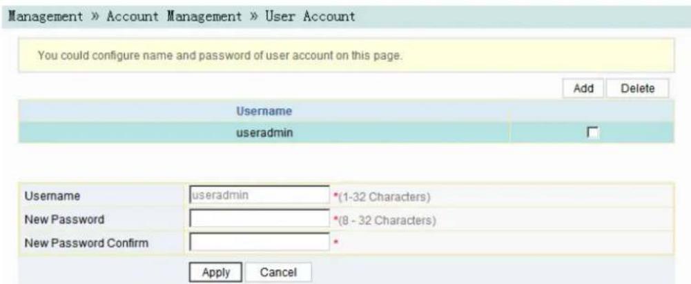
Figure3-51UserAccountManagement
- Addordeleteacommonuseraccountormodifythepasswordofacommon useraccountsrequired.
- ClickApplytosaveandapplytheconfiguration.
3.6.1.2 MaintenanceAccountManagement
Userscanmodifytheusernameandpasswordofthecurrentaccount.
- Select Management in the navigation bar. Select Account Management→MaintenanceAccountfromtheleftlinkbartoopenthemaintenanceaccount managementpage,asshowninFigure3-52.

Figure3-52 Maintenance Account Management
- Modify the username or password of the current accounts required.
- ClickApplytosaveandapplytheconfiguration.
3.6.2 Device Management
TheONTprovides multiple device management functions such as restoringsome of the configuration data, restoring all configuration data, local upgrade, configuration backup, FTP server, device reboot, and NTP time calibration.
3.6.2.1 Restoring theConfigurationData
RestorefactorysettingsoftheONT,includingusernameandpasswordforWeb login,SSIDandpasswordforwirelessnetwork,etc.
- Select Management in the navigation bar. Select Device Management→Restorefromtheleftlinkbartoopentheconfigurationrestoringpage,as showninFigure3-53.

Figure3-53RestoringtheConfigurationData
- Click Restore and then click OK in the alert box that appears. Wait until the configurationdataarecompletelyrestored.
3.6.2.2RestoringAlltheConfigurationData
RestorealltheconfigurationdataoftheONTtofactorysettings.
- Select Management in the link bar and select Device Management→Restore Allontheleftsidetoopentheconfigurationrestorationpage,asshownin Figure3-54.

Figure3-54RestoringAlltheConfigurationData
- Click Restore All and then click OK in the alert box that appears. Wait until the configurationdataarecompletelyrestored.
3.6.2.3 Local Upgrade
SelectthelocalfileandupgradetheONTsoftware.Duringupgrade,donotpoweroffthedeviceorperformotheroperationstoppreventdamagetothedevice.
- Select Management in the navigation bar. Select Device Management→LocalUpgradefromtheleftlinkbartoopenthelocalupgradepage,asshown inFigure3-55.

Figure3-55LocalUpgrade
- ClickBrowse. In the dialog box that appears, select the devices software version to be upgraded and click Opentougradethe ONT software.
- Whentheupgradesucceeds, thepagewillpromptfordevicerebooting. Click Reboot. Afterrebooting, thedevicewillbeupgradedtothenewversion.

Note:
Aftertheupgrade,youcanviewtheSoftwareVersioninthedevice informationpagetocheckwhetherthecurrentversioniscorrect.
3.6.2.4ConfigurationBackup
BackupandsavetheONTconfigurationfilesforrestoringconfigurationdatalater on.Beforebackup,enabletheFTPtoolinthecomputer.
- Select Management in the navigation bar. Select Device Management→ConfigBackupfromtheleftlinkbartoopentheconfigurationbackuppage,as showninFigure3-56.

Figure3-56ConfigurationBackup
- Configureparametersrelevanttofilebackup. Fordetailsoftheparameters, see Table3-28.
- ClickApplytosavetheconfigurationbackupfile.
Table3-28ParametersforConfigurationBackup
| ItemDescription | |
| UsernameTheFTPusername. | |
| Password | TheFTPpassword. |
| LocalhostIPThelocallPaddress. | |
| FileName | TheexistingfilenameoftheONT. |
3.6.2.5 FTP Server
WiththeFTPserverfunctionoftheONT enabled, userscanaccesstheONT resourcesviatheFTPclientendonthePC.
- Select Management in the navigation bar. Select Device Management→FTP ServerfromtheleftlinkbartoopentheFTPserverconfigurationpage, as showninFigure3-57.

Figure3-57FTPServer
-
EnableordisabletheFTPserverfunctionaccordingtotherequirement.Select Enable and then enter the Username and Password for connection with the FTPserver.
-
ClickApplytosaveandapplytheconfiguration.
3.6.2.6DeviceReboot
- Select Management in the navigation bar. Select Device Management→DeviceRebootfromtheleftlinkbartoopenthedevicerebootpage,asshown inFigure3-58.
Management » Device Management » Device Reboot
On this page, you can reboot the device by clicking the button below.
Reboot
Figure3-58DeviceReboot
- Click Reboot and click OK in the alert box that appears and wait for the device toreboot.

Caution:
Savetheconfigurationdatabeforererebootingthedevicetopreventlossof thedata.
Afterthedeviceisrebooted, waitforabouttwominutesbeforenextlogin totheWebGUIofthedevice.
3.6.2.7 NTPTimeCalibration
UserscanobtaintheprecisetimebyconnectingtheONTtoanNTPserver.
- Select Management in the navigation bar. Select Device Management→NTP CheckTimefromtheleftlinkbartoopentheNTPchecktimepage,asshown inFigure3-59.

Figure3-59NTPTimeCalibration
- ConfigureparametersrelevanttotheNTPtimecalibration.Fordetailsofthe parameters,seeTable3-29.
- ClickCheckTimetosaveandapplytheconfiguration.
Table3-29ParametersforNTPTimeCalibration
| Item | Description |
| EnableNTP CheckTime | SelectwhethertoenabletheNTPtimecalibrationfunction. |
| Seconds | Setsthetimeintervalforsynchronizationwiththetimeserver. |
| FirstNTPServerEnterthelPaddressoftheactiveNTPserver. | |
| SecondNTP Server | EnterthelPaddressofthestandbyNTPserver. |
| TimeZone | Selectthetimezoneaccordingtothelocationofthedevice. |
| CurrentTime | WhenNTPCheckTimeisenabled,timewillbecalibratedaccordingtothe locationofthedevice,andthelocaltimewillbedisplayed.WhenNTPCheckTimeisdisabled,thesysteminitialtime(1970-01-01)or thepreviouscalibratedtimewillbedisplayed. |
| BindingWAN Connections | SelecttheWANconnectiontypefortimecalibration. |
3.6.3LogManagement
ThelogfilesrecordkeyoperationsandactionsontheONT.Userscanviewthe informationsavedinthelogasneeded.
Select Management in the navigation bar. Select Log→Log from the left link bar to opentheloginformationpage,asshowninFigure3-60.
You can view log on this page.
Log Information
Manufacturer:FiberHome;
ProductClass:AN5506-04-FAT
SerialNumber:FHTT-02744968;
ONU IP:192.168.1.1;
HWVer:WKE2.134.285FAT1;
SWVer:RP2608(00.00);
1970-1-1 0:20:18 [Informational] webLogin finished!
1970-1-1 0:20:30 [Informational] webLogin finished!
1970-1-1 0:21:24 [Informational] webLogin finished!
1970-1-1 0:2:35 [Informational] webLogin finished!
1970-1-1 0:2:40 [Informational] webLogin finished!
1970-1-1 0:3:8 [Informational] webLogin finished!
1970-1-1 0:3:14 [Informational] webLogin finished!
1970-1-1 0:5:43 [Informational] webLogin finished!
1970-1-1 0:6:31 [Informational] change password success!
1970-1-1 0:6:34 [Informational] webLogout finished!
1970-1-1 0:6:40 [Informational] webLogin finished!
1970-1-1 0:6:43 [Informational] get restore finished!
Figure3-60Log
4HandlingCommonProblems
Thischapterintroduceshowtohandlecommonproblemsencounteredinequipmentoperationandservicetest.
PowerStatusIndicatorLEExtinguished
RegisterStatusIndicatorLEDExtinguished
OpticalSignalStatusIndicatorLEDBlinking
EthernetInterfaceStatusIndicatorLEDExtinguished
FailingtoDetecttheONTUsingWi-Fi
FailingtoAccessLocalWebLoginGUIandFailingtoPing192.168.1.1
FailingtoAccessInternetUsingtheLANPort
FailingtoAccessInternetUsingWi-Fi
MeasuredInternetAccessRateOutofNormalRange
TestofVoiceServiceFailed
4.1 PowerStatusIndicatorLEDExtinguished
Handle the problem according to the procedures below.
- Checkwhetherthemainssupplyisnormal.
- Check whether the power adapter match the device.
- Checkwhetherthepowerbuttonispresseddown.
- Checkwhetherthepowercableconnectionisnormal.
4.2RegisterStatusIndicatorLEDExtinguished
Handle the problem according to the procedures below.
- Checkwhetherthedevicepowersupplyisnormal.
- Checkwhethertheopticalfiberconnectionisnormal.
- Check whether the ON has obtained the ISP authorization.
- Checkwhethertheopticalinterfaceisnormal;ifnot,replacethedevice.
4.3OpticalSignalStatusIndicatorLEDBlinking
Handle the problem according to the procedures below.
- Checkwhethertheopticalfiberisdamaged.
- Checkwhethertheopticalfiberisconnectedtothecorrectinterface.
- CheckwhethertheRxopticalpoweroftheONT(measuredwiththeoptical powermeter)isbelowspecifications.
- Check whether the ONToptical module is aged or damaged.
- Check whether the local device is faulty.
4.4 Ethernet Interface Status Indicator LED Extinguished
Handle the problem according to the procedures below.
- Checkwhetherthenetworkcableisdamagedorconnectedincorrectly.
- Checkwhetherthecolor-codingschemeofthenetworkcableisincorrect;ifso, replaceitwithastandardCAT-5twistedpairnetworkcable.
- Check whether thenetwork cable length exceeds the allowed range (100m).
4.5 Failing to Detect the ONT Using Wi-Fi
Handle the problem according to the procedures below.
- Check whether the wireless function is disabled for the ONT and whether the SSIDissettoHiddenso that thenetwork is invisible.
- Check whether thenetworkcarddriveofthecomputerisinstallednormally and whether the WLAN function of the wireless terminal (such as computer and telephone) is enabled.
- Adjust the position of the ONT to reduce the barrier on the wireless channel (such as walls) and makes sure the distance between the ONT and the wireless terminal is within there required range.
4.6 FailingtoAccessLocalWebLoginGUland FailingtoPing192.168.1.1
Handle the problem according to the procedures below.
- CheckwhethertheLANportindicatorLEDissolidON;ifnot,replace the networkcable.
- CheckwhetherthecomputerissetwithafixedIPaddressinthenetwork segmentof192.168.1.x.
4.7 FailingtoAccessInternetUsingtheLANPort
Handle the problem according to the procedures below.
-
Check whether the computer is set with a fixed IP address. If yes, modify the configurations that the computer can obtain an IP address automatically. Then retry the connection.
-
If the computer obtains an IP address automatically, check whether the computer has obtained an IP address in thenetwork segment of 192.168.x.x.
- Contact the personnel in the network management center to check whether the WAN is connected correctly and bound with the LAN port.
4.8 FailingtoAccessInternetUsingWi-Fi
Handle the problem according to the procedures below.
- CheckwhetherthecomputerisconnectedtotheONT'sWi-Fisignalcorrectly andcanobtainanIPaddressautomatically.
- Contact the personnel in the network management center to check whether the WAN connection is bound with the Wi-Fi port correctly.
4.9 Measured Internet Access Rate Out of Normal Range
Contact the personnel in the network management center to check whether the bandwidth profile is configured correctly and bound to the ONT.
4.10 TestofVoiceServiceFailed
Handle the problem according to the procedures below.
- Checkwhetheryoucanhearthecurrenttonewhenyougooff-hook;ifno, checkwhetherthephonecableisconnectedcorrectly.
- Checkwhetheryoucanhearthedialtonewhenyougooff-hook;ifno,contact thenetworkmanagementcentertocheckwhetherthevoiceserviceworkorder hasbeendeliveredcorrectlyandwhethertheuplinkdevicehasdeliveredthe configurationdatatothevoiceserviceportoftheONT.
- LogintotheONTtocheckwhetherithasobtainedanIPaddressforthevoice service.
- Contact the soft switch platform to check whether the voice encoded data have been configured.
5StandardsandProtocols
| ClassificationStandardNumberTitle | ||
| GPON | ITU-TG.984.1 | Gigabit-capablepassiveopticalnetworks(GPON):Generalcharacteristics |
| ITU-TG.984.2 | Gigabit-capablePassiveOpticalNetworks(GPON):PhysicalMediaDependent(PMD)layerspecification | |
| ITU-TG.984.3 | Gigabit-capablePassiveOpticalNetworks(G-PON):Transmissionconvergencelayerspecification | |
| ITU-TG.984.4 | Gigabit-capablepassiveopticalnetworks(G-PON):ONTmanagementandcontrolinterfacespecification | |
| Ethernet | IEEE802-2001 | IEEEStandardforLocalandMetropolitanArea Networks:OverviewandArchitecture |
| IEEE802.1D-2004 | IEEEStandardforLocalandmetropolitanarea networks:MediaAccessControl(MAC)Bridges | |
| IEEE802.1Q-2005 | IEEEStandardforLocalandMetropolitanArea Networks-VirtualBridgedLocalAreaNetworks-Amendment4:ProviderBridges | |
| IEEE802.1ad | IEEEStandardforLocalandMetropolitanArea Networks-VirtualBridgedLocalAreaNetworks-Amendment4:ProviderBridges | |
| IEEE802.1x-2004 | IEEEStandardforLocalandMetropolitanArea NetworksPort-BasedNetworkAccessControl | |
| IEEE802.1ag-2007 | IEEEStandardforLocalandMetropolitanArea NetworksVirtualBridgedLocalAreaNetworks Amendment5:ConnectivityFaultManagement | |
| IEEE802.3-2005 | IEEEStandardforInformationtechnology-Telecommunicationsandinformationexchange betweensystems-Localandmetropolitanarea networks-SpecificrequirementsPart3:Carrier SenseMultipleAccesswithCollisionDetection (CSMA/CD)AccessMethodandPhysicalLayer Specifications | |
| IEEE802.3z | GigabitEthernetStandard | |
| IEEE802.1p | Trafficclassexpeditinganddynamicmulticast filtering.Describesimportantmethodsforproviding QoSatMAClevel | |
| TR-101 | MigrationtoEthernet-BasedBroadbandAggregation | |
| TR-143 | EnablingNetworkThroughputPerformanceTestsand StatisticalMonitoring | |
| VoIP | ITU-TG.711 | Pulsecodemodulation(PCM)ofvoicefrequencies |
| ITU-TG.711.1 | WidebandembeddedextensionforG.711pulsecode modulation | |
| ITU-TG.722 | 7kHzaudio-codingwithin64kbit/s | |
| ITU-TG.723.1 | Dualratespeechcoderformultimedia communicationstransmittingat5.3and6.3kbit/s | |
| ITU-TG.729 | Codingofspeechat8kbit/susingconjugate-structure algebraic-code-excitedlinearprediction(CS-ACELP) | |
| ITU-TG.729.1 | G.729basedEmbeddedVariablebit-ratecoder:An8-32kbit/sscalablewidebandcoderbitstream interoperablewithG.729 | |
| ITU-TG.165EchoCancellers | ||
| ITU-TG.168 | Digitalnetworkechocancellers | |
| Multicast | IETFRFC2236 | InternetGroupManagementProtocol,Version2 |
| IETFRFC3376 | InternetGroupManagementProtocol,Version3 | |
| IETFRFC4541 | ConsiderationsforInternetGroupManagement Protocol(IGMP)andMulticastListenerDiscovery (MLD)SnoopingSwitches | |
| Time | IETFRFC1305 | NetworkTimeProtocol(Version3)Specification, ImplementationandAnalysis |
| IETFRFC2030 | SimpleNetworkTimeProtocol(SNTP)Version4for IPv4,IPv6andOSI | |
| EMC | EN300386 | ElectromagneticcompatibilityandRadiospectrum Matters(ERM);Telecommunicationnetwork equipment;ElectromagneticCompatibility(EMC) requirements |
| CISPR22 (EN55022) | Informationtechnologyequipment-Radio disturbancecharacteristics-Limitsandmethodsof measurement | |
| CISPR24 (EN55024) | Informationtechnologyequipment-Immunity characteristics-Limitsandmethodsofmeasurement | |
| Other | ||
AppendixAAbbreviations
| ONT | OpticalNetworkTerminal |
| FTTH | FiberToTheHome |
| GPON | Gigabit-capablePassiveOptical Network |
| ODN | OpticalDistributionNetwork |
| OLT | OpticalLineTermination |
| MTBF | MeanTimeBetweenFailure |
| DBA | DynamicBandwidthAllocation |
| XML | ExtensibleMarkupLanguage |
| GEM | GPONEncapsulationMode |
| ATM | AsynchronousTransferMode |
| OAM | Operation,AdministrationAnd Maintenance |
FECForwardErrorCorrection
| TDMA | TimeDivisionMultipleAccess |
| PLOAM | PhysicalLayerOperations,AdministrationandMaintenance |
| OMCI | ONUManagementandControlInterface |
T-CONTTransmissionContainer
| NSR | NetworkSecurityRecorder |
| AES | AdvancedEncryptionStandard |
MACMediumAccessControl
| IGMP | InternetGroupManagementProtocol |
| VLAN | VirtualLocalAreaNetwork |
| QoS | QualityofService |
ACLAccessControlList
| WRR | WeightedRoundRobin |
| DHCP | DynamicHostConfigurationProtocol |
| PPPoE | PointtoPointProtocoloverEthernet |
| NAT | NetworkAddressTranslation |
| DMZ | DemilitarizedZone |
| ARP | AddressResolutionProtocol |
| UPnP | UniversalPlugandPlay |
| DoSDenialofService | |
| URL | UniformResourceLocator |
| HTTPS | HyperTextTransferProtocoloverSecureSocketLayer |
| CATVCableAntennaTelevision | |
| SIPSessionInitiationProtocol | |
| VoIPVoiceoverInternetProtocol | |
| RTP | Real-timeTransportProtocol |
| SSIDServiceSetIdentifier | |
| WAN | WideAreaNetwork |
| LAN | LocalAreaNetwork |
| WLAN | WirelessLocalAreaNetworks |
| MTUMaximumTransmissionUnit | |
| PPPoE | PointtoPointProtocoloverEthernet |
| DTMF | DualToneMultiFrequency |
| VPN | VirtualPrivateNetwork |
| DDNS | DynamicDomainNameServer |
| FTPFileTransferProtocol | |
| CPE | CustomerPremiseEquipment |
| EMC | ElectroMagneticCompatibility |
| GUI | GraphicalUserInterface |
| HG | HomeGateway |
| ICMP | InternetControlMessageProtocol |
| IPInternetProtocol | |
| LAN | LocalAreaNetwork |
| MLD | MulticastListenerDiscover |
| PON | PassiveOpticalNetwork |
| POTS | PlainOldTelephoneService |
| SP | StrictPriority |
| STB | SetTopBox |
| TCPTransmissionControlProtocol | |
| UDP | UserDatagramProtocol |
ProductDocumentationCustomerSatisfactionSurvey
ThankyouforreadingandusingtheproductdocumentationprovidedbyFiberHome.Pleaseatakeamomentto completethissurvey.Youranswerswillhelpustoimprovethedocumentationandbettersuityourneeds.Your responseswillbeconfidentialandgivenseriousconsideration.Thepersonalinformationrequestedisusedfor nootherpurposesthantorespondtoyourfeedback.
| Name | |
| PhoneNumber | |
| EmailAddress | |
| Company |
Tohelpusbetterunderstandyourneeds,pleasefocusyouranswersonasingledocumentationoracomplete documentationset.
| DocumentationName | |
| CodeandVersion |
Usageoftheproductdocumentation:
- How oftendoyouusethedocumentation?
□ Frequently □ Rarely □ Never □ Other (please specify) ____
- Whendoyouusethedocumentation?
□ in starting up a project □ in installing the product □ in daily maintenance □ in trouble shooting □ Other(pleasespecify) ____
- What is the percentage of the operations on the product for which you can get instruction from the documentation?
□ 100% □ 80% □ 50% □ 0% □ Other (please specify) ____
- Are you satisfied with the promptness with which we updated the documentation?
□Satisfied □Unsatisfied(youradvice)
- Which documentation form do you prefer?
□ Print edition □ Electronic edition □ Other (please specify) ____
Qualityoftheproductdocumentation:
- Istheinformationorganizedandpresentedclearly?
□Very □Somewhat □Notatall(youradvice)
- Howdoyoulikethelanguagestyleofthedocumentation?
□Good □Normal □Poor(pleasespecify)
-
Areanycontentsinthedocumentationinconsistentwiththeproduct?
-
Istheinformationcompleteinthedocumentation?
□Yes
□No(Pleasespecify)
- Are the product working principles and the relevant technologies covered in the documentation sufficient for youtogetknownandusetheproduct?
□Yes
□No(Pleasespecify)
- Can you successfully implement a task following the operation steps given in the documentation?
□Yes(Pleasegiveanexample)
□No(Pleasespecifythereason)
-
Which part of the documentation are you satisfied with?
-
Which part of the documentation are you unsatisfied with? Why?
- WhatisyouropinionontheFiguresinthedocumentation?
□Beautiful □Unbeautiful(youradvice)
□Practical □Unpractical(youradvice)
- Whatisyouropiniononthelayoutofthedocumentation?
□Beautiful □Unbeautiful(youradvice)
- Thinking of the documentations you have ever read offered by other companies, how would you compare our documentation to them?
Productdocumentationsfromothercompanies:
Satisfied(pleasespecify)
Unsatisfied(pleasespecify)
- Additional comments about our documentation or suggestions on how we can improve:
Thankyouforyourassistance.Pleasefaxorsendthecompletedsurveytousatthecontactinformation includedinthedocumentation.Ifyouhaveanyquestionsorconcernsaboutthissurveypleaseemailatedit@fiberhome.com

- Thankyouforchoosingourproducts.
- FiberhomeTelecommunicationTechnologiesCo.,Ltd.
- LegalNotice
- Allrightsreserved
- SafetyPrecautions
- Contents
- Safety Precautions....I
- Web Configuration Guide....18
- Network....31
- Security 56
- Application....72
- Management 79
- Handling Common Problems 87
- 1DocumentationGuide
- DocumentOrientation
- IntendedReaders
- VersionInformation
- Content
- 2ProductIntroduction
- ProductPositioning
- 2.2ProductSpecification
- 2.3InterfaceSpecifications
- GPONInterface
- LANInterface
- 2.3.3POTSInterface
- Wi-FilInterface
- 2.3.5USBInterface
- Introduction to the HG6143D
- Appearance
- Appearance
- InterfacesandButtons
- IndicatorLEDs
- ProductCharacteristics
- GPONAccessCapability
- AbundantServiceTypes
- 3.Wi-FiWirelessAccess
- NetworkStorageandFileSharing
- GatewayFunctions
- RemoteAutomaticServiceProvisioning, Maintenance and Management
- Functions and Features
- 3WebConfigurationGuide
- LocalLogintotheWebConfigurationGUI
- Prerequisites
- PlanningData
- OperationProcedure
- Note:
- 3.2Status
- DeviceInformation
- Wireless Network Status
- Wireless Network Status
- 3.2.2.2Statusofthe5GWirelessNetwork
- 3.2.2.3Wi-FiUserList
- 3.2.3WANSideStatus
- LANSideStatus
- LANSideStatus
- 3.2.4.2DHCPUserList
- 3.2.5OpticalPowerStatus
- 3.2.6VoiceStatus
- 3.3Network
- 3.3.1WLANSettings
- BasicParameters
- AdvancedConfiguration
- 3.3.1.3Wi-FiControl
- 3.3.1.45GBasicParameters
- 3.3.1.55GAdvancedConfiguration
- 3.3.1.65GWi-FiControl
- 3.3.1.7WPSSConfiguration
- LAN Settings
- Broadband Settings
- DHCP Server
- Authentication Settings
- IPv6
- VoiceConfiguration
- KeyParameters
- Basic Parameters
- AdvancedConfiguration
- Security
- Firewall
- FirewallControl
- 3.4.1.5DHCPFiltering
- Anti-portScan
- MACAddressFiltering
- RemoteControl
- DynamicDoS
- HTTPS
- Caution:
- 3.5Application
- 3.5.1VPN
- 3.5.2DDNS
- PortForwarding
- 3.5.4NAT
- 3.5.6DMZ
- NetworkDiagnosis
- Network Diagnosis
- 3.5.7.2NatSession
- 3.6Management
- 3.6.1UserManagement
- UserAccountManagement
- MaintenanceAccountManagement
- Device Management
- Restoring theConfigurationData
- 3.6.2.2RestoringAlltheConfigurationData
- Local Upgrade
- 3.6.2.4ConfigurationBackup
- FTP Server
- 3.6.2.6DeviceReboot
- NTPTimeCalibration
- 3.6.3LogManagement
- Log Information
- 4HandlingCommonProblems
- PowerStatusIndicatorLEDExtinguished
- 4.2RegisterStatusIndicatorLEDExtinguished
- 4.3OpticalSignalStatusIndicatorLEDBlinking
- Ethernet Interface Status Indicator LED Extinguished
- Failing to Detect the ONT Using Wi-Fi
- FailingtoAccessLocalWebLoginGUland FailingtoPing192.168.1.1
- FailingtoAccessInternetUsingtheLANPort
- FailingtoAccessInternetUsingWi-Fi
- Measured Internet Access Rate Out of Normal Range
- TestofVoiceServiceFailed
- 5StandardsandProtocols
- AppendixAAbbreviations
- ProductDocumentationCustomerSatisfactionSurvey
- Usageoftheproductdocumentation:
- Qualityoftheproductdocumentation:
Brand : FiberHome
Model : HG6143D
Category : Router