
HG6244C - Router FiberHome - Free user manual and instructions
Find the device manual for free HG6244C FiberHome in PDF.


| Product Type | GPON ONT/Router Combo |
| Brand | FiberHome |
| Model | HG6244C |
| Dimensions (W x D x H) | 200 x 150 x 35 mm |
| Weight | 350 g |
| Power Supply | 12V DC, 1A |
| Wi-Fi Standards | IEEE 802.11a/b/g/n/ac (Wi-Fi 5) |
| Frequency Bands | 2.4 GHz and 5 GHz |
| Maximum Wireless Data Rate | Up to 1200 Mbps (2.4 GHz: 300 Mbps, 5 GHz: 867 Mbps) |
| WAN Port | 1 x GPON (SC/APC connector) |
| LAN Ports | 4 x 10/100/1000 Mbps Gigabit Ethernet |
| USB Port | 1 x USB 2.0 |
| Antenna | 2 internal antennas |
| Power Consumption | 12W (max) |
| Operating Temperature | 0°C to 40°C |
| Storage Temperature | -20°C to 70°C |
| Humidity | 10% to 90% (non-condensing) |
| Firewall | Built-in SPI firewall |
| VLAN Support | 802.1Q VLAN |
| Bridge Mode | Supported |
| Maintenance and Cleaning | Wipe with a soft, dry cloth; do not use liquids or cleaning agents. |
| Safety Instructions | Avoid heat sources, keep ventilation slots clear, use only provided power adapter. |
| Spare Parts and Repairability | Power adapter available; device not user-serviceable, contact support for repairs. |
| General Information | FiberHome HG6244C is a GPON optical network terminal with integrated Wi-Fi router, suitable for fiber broadband connections. |
Frequently Asked Questions - HG6244C FiberHome
User questions about HG6244C FiberHome
0 question about this device. Answer the ones you know or ask your own.
Ask a new question about this device
Download the instructions for your Router in PDF format for free! Find your manual HG6244C - FiberHome and take your electronic device back in hand. On this page are published all the documents necessary for the use of your device. HG6244C by FiberHome.
USER MANUAL HG6244C FiberHome
Thankyouforchoosingourproducts.
Weappreciateyourbusiness.Yoursatisfactionisourgoal. Wewillprovideyouwithcomprehensivetechnicalsupport andafter-salesservice.Pleasecontactyourlocalsales representative,servicerepresentativeordistributorforany helpneededatthecontactinformationsshownbelow.
FiberhomeTelecommunicationTechnologiesCo.,Ltd.
Address: No.67, GuangguChuangyeJie, Wuhan, Hubei, China
Zipcode:430073
Tel:+60379600860/0884(forMalaysia)
+919899855448(forSouthAsia)
+59345014529(forSouthAmerica)
Fax:+862787178521
Website:http://www.fiberhomegroup.com
LegalNotice
缘上通信®
FiberHome®
GONST®
FONST®
e-Fim®
CiTRANS®
E-jet®
IBAS®
Freelink®
FonSWeaver®
OTNPlanner ^TM
SmartWeaver™
aretrademarksofFiberHomeTelecommunicationTechnologiesCo.,Ltd. (HereinafterreferredtoasFiberHome)
Allbrandnamesandproductnamesusedinthisdocumentareusedfor identificationpurposesonlyandaretrademarksorregisteredtrademarks oftheirrespectiveholders.
Allrightsreserved
Nopartofthisdocument(includingtheelectronicversion)maybe reproducedortransmittedinanyformorbyanymeanswithoutprior writtenpermissionfromFiberHome.
Informationinthisdocumentissubjecttochangewithoutnotice.
SafetyPrecautions
Foryourcorrectandsafeoperationsontheequipment,pleasecarefullyreadand strictlyobservethefollowingsafetyinstructions:
◆ Highopticalpowercancausebodilyharm,especiallytoeyes. Neverlook directly into the end of the optical transmitter fiber jumper or the end of its active connector.
◆ Exercisecareifyoumustbendfibers.Ifbendsarenecessary,thefiberbending radiusshouldneverbelessthan38mm.
◆Overloadedpowersocketsordamagedcablesandconnectorsmaycause electricshockorfire.Regularlycheckrelatedelectriccables.Ifanyofthemis damaged,replaceitimmediately.
◆Usethepowersupplyadapterprovidedinthepackageonly.Usingother adaptersmaycauseequipmentdamageoroperationfailures.
◆ Installtheequipmentinawellventilatedenvironmentwithoutthightemperatureordirectsunlighttoprotecttheequipmentanditscomponentsfromoverheating,whichcanresultindamage.
◆ Disconnect the power in lightning weather and disconnect all the wires and cables on the device (such as the power cable, network cable and phone cable), soastoprevent device from being damaged by lightning.
◆ Donotplacethisequipmentindampornearmoistureenvironment.Waterwill leadtoabnormaloperationofdeviceandeventhedangercausedbyshort circuit.
◆ Donotlaythisequipmentonanunsteadybase.
Contents
Safety Precautions....I
1 Documentation Guide....1
2 Product Introduction....2
2.1 Product Positioning....3
2.2 Product Specifications ....3
2.3 Interface Specifications....4
2.3.1GPONInterface....4
2.3.2 LANInterface....4
2.3.3 POTS Interface....5
2.3.4 Wi-Fi Interface ....5
2.3.5 USB Interface 6
2.4 Introduction to the HG6244C....6
2.4.1 Appearance....6
2.4.2 ProductCharacteristics....10
2.4.3 FunctionsandFeatures....12
2.4.4 Technical Specifications....16
3 Web Configuration Guide....17
3.1 Logging into Web Configuration GUI Locally.....18
3.2 Status....24
3.2.1 Device Information....25
3.2.2 Wireless Network Status 25
3.2.3 WAN Side Status 26
3.2.4 LANSideStatus....27
3.2.5 Optical Power Status 28
3.2.6 VoiceStatus....28
3.3 Network....29
3.3.1 WLAN Settings 29
3.3.2 LAN Settings 34
3.3.3 Broadband Settings 36
3.3.4 DHCP Server....39
3.3.5 Authentication Setting....41
3.3.6 VoiceConfiguration....42
3.4 Security....49
3.4.1 Firewall....49
3.4.2 RemoteControl....60
3.4.3 Dynamic DoS 60
3.4.4 HTTPS....61
3.5 Application....62
3.5.1 DDNS....62
3.5.2 PortForwarding....63
3.5.3 NAT....64
3.5.4 UPnP 65
3.5.5 DMZ....66
3.5.6 Network Diagnosis....66
3.6 Management 67
3.6.1 Account Management....67
3.6.2 Device Management....69
3.6.3 Log Management....73
4 Handling Common Problems 75
4.1 Power Status Indicator LED Extinguished....76
4.2RegisterStatusIndicatorLEDExtinguished....76
4.3 OpticalSignalStatusIndicatorLEDBlinking....76
4.4 Ethernet Interface Status Indicator LED Extinguished....76
4.5 FailingtoAccessLocalWebLoginGUIandFailingtoPing
192.168.1.1 77
4.6 FailingtoAccessInternetUsingtheLANPort....77
4.7 Measured Internet Access Rate Lower or Higher Than The Standard Value....77
4.8 Connection to IPTV Failed 78
4.9IPTVPictureSuspended....78
4.10 Test of Voice Service Failed 78
5 Standards and Protocols....79
Appendix A Abbreviations....81
1DocumentationGuide
DocumentOrientation
HG6244CProductManualintroducesthepositioning,features,functions,technical specificationsoftheONT(OpticalNetworkTerminal)productHG6244Caswellas Webconfigurationsandhandlingofcommonproblems,sothatreaderscanhavean overallknowledgeabouttheHG6244C.
IntendedReaders
◆ Marketingpersonnel
◆Commissioningengineers
◆Operationandmaintenanceengineers
VersionInformation
| VersionVersionInformation | |
| AInitialversion | |
Content
| Chapter | Content |
| ProductIntroduction | ◆Productpositioning◆Productspecifications◆Interfacespecifications◆IntroductiontotheHG6244C |
| WebConfigurationGuide | ◆LoggingintoWebconfigurationGUIlocally◆Status◆Network◆Security◆Application◆Management |
| HandlingCommonProblems | Introduceshowtohandlecommonproblemsencountered duringproductoperationandservicetest,including abnormalstatusofindicatorLEDs,failingtoaccessthe Internet,failureofvoiceservicetest,etc. |
| StandardsandProtocols | Internationalstandardsandcommunicationsprotocols |
2ProductIntroduction
ProductPositioning
ProductSpecifications
InterfaceSpecifications
IntroductiontotheHG6244C
2.1 ProductPositioning
TheHG6244CisanFTTH-typeGPONONT.Itprovidesuserswithcommunication andentertainmentservicesintheformofdata,voice,video,andsoon,tomeetthe integratedaccessdemandoffamiliesandsmall-scaledenterprises.
SeeFigure2-1forthenetworkpositioningoftheHG6244C.

flowchart
graph LR
    A["Phone"] --> B["STB"]
    C["IPTV"] --> B
    D["PC"] --> E["Wi-Fi subscriber terminal"]
    B --> F["ONT"]
    E --> G["ODN"]
    F --> H["OLT"]
    G --> H
    H --> I["IP Network"]
    I --> J["Internet"]
    I --> K["IPTV Server"]
    I --> L["Softswitch/IMS"]
    I --> M["ITMS"]
    I --> N["UNM2000"]
Figure2-1 Network Application of the HG6244C
2.2ProductSpecifications
ThetablesbelowlisttheinterfacesontheHG6244Candtheservicessupportedby theONTforusers'referenceonONTconfiguration.
Table2-1liststheinterfacessupportedbytheHG6244C.
Table2-1 Interfaces Supported by the HG6244C
| ONTType | EthernetInterface Quantity | POTS Interface Quantity | Wi-FilInterface | USB Interface Quantity | CATV Interface Quantity |
| HG6244C | 4(GE) | 2 | 1 | 1 |
Table2-2liststheservicetypessupportedbytheHG6244C.
Table2-2ServiceTypesSupportedbytheHG6244C
| ONTType | InternetServiceMulticastServiceVoiceServiceWi-FiService | |
| HG6244C | ||
| Note: “√”indicates “supported”; “×” indicates “not supported”. | ||
ServiceReliability
TheHG6244CsupportsMTBFupto30000hours.
2.3InterfaceSpecifications
2.3.1 GPONInterface
SeeTable2-3forthespecificationsoftheGPONinterface.
Table2-3GPONInterfaceSpecifications
| Parameter | Specification |
| Standardcompliance | ITU-TG.984,ClassB+ |
| Transmissionrate | Rx:2.5Gbit/s;Tx:1.25Gbit/s |
| Interfacemode | Single-mode |
| Interfacetype | SC/APC |
| Maximumtransmissiondistance | 20km |
| Centralwavelength | Tx:1310nm;Rx:1490nm |
| Opticalpower | Txopticalpower:0.5dBmto5.0dBmRxopticalpower:-8dBmto-29dBm |
| Extinctionratio | Morethan10dB |
| Receivingsensitivity | -27dBmto-29dBm |
| Maximumoverloadopticalpower | -8dBm |
2.3.2 LANInterface
Table2-4showsthespecificationsoftheLANinterface.
Table2-4LANInterfaceSpecifications
| Parameter | Specification |
| Standardcompliance | IEEE802.3ab |
| Interfacetype | RJ-45 |
| Interfacerate | 10Mbit/s, 100Mbit/sor1000Mbit/s |
| Maximumtransmission distance | 100m |
| Workingmode | Supportsfull-duplexorhalf-duplexand10/100/1000Mauto negotiation. |
| Specificationsofthecable used | CAT-5unshieldedtwistedpair |
2.3.3POTSInterface
Table2-5showsthespecificationsofthePOTSinterface.
Table2-5POTSInterfaceSpecifications
| Parameter | Specification |
| Interfacetype | RJ-11 |
| Transmissionrate64Kbit/s | |
| CabletypeTwisted-paircable | |
| LinecodePCM |
2.3.4Wi-FilInterface
| Item | Specification |
| StandardcomplianceIEEE80 | 2.11b/g/n |
| Operatingband | 2.4GHz |
| Specifications | FourSSIDsand13workingchannelsforthe2.4GHzband.Automaticrateadjustmentandlaunchedpoweradjustmentforthe2.4GHzband. |
| Authenticationmode | OPEN,SHARED,WPA-PSK,WPA2-PSKandWPA-PSK/WPA2-PSK |
| Encryptionmode | WEP,TKIP,AESandTKIP/AES |
2.3.5USBInterface
Table2-6showsthespecificationsoftheUSBinterface.
Table2-6USBInterfaceSpecifications
| Parameter | Specification |
| Standardcompliance | USB2.0/USB1.1 |
| Transmissionrate20MB/s |
2.4 Introduction to the HG6244C
2.4.1 Appearance
The following describes the appearance of the HG6244C, including the overall look, interfaces, buttons, and indicator LEDs.

Note:
Thepictureshereareonlyforreference.
Appearance
TheoverallappearanceoftheHG6244CisshowninFigure2-2.

natural_image
Black electronic device with decorative swirl pattern and 'FibRlona' branding (no readable text or symbols beyond branding)Figure2-2OverallAppearanceoftheHG6244C
InterfaceandButton
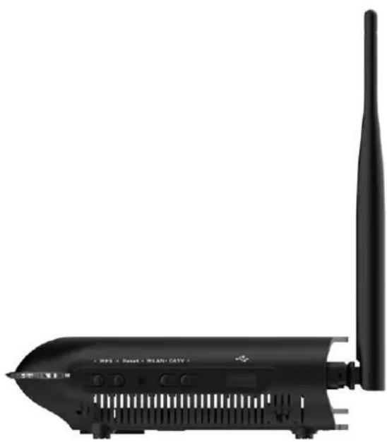
InterfacesandbuttonsoftheHG6244Carelocatedontherear,sideandback panelsoftheequipment.Figure2-3showstherearpanel,Figure2-4showsthe sidepanel,andFigure2-5showsthebackpanel.

natural_image
Front view of a black wireless router with two antennas and ports (no visible text or labels)Figure2-3RearPaneloftheHG6244C
natural_image
Black wireless router device with antenna and ventilation slots (no visible text or symbols)Figure2-4SidePaneloftheHG6244C

natural_image
Top-down view of a black electronic device casing with ventilation grilles and mounting points (no visible text or symbols)Figure2-5BackPaneloftheHG6244C
Table2-7 describestheinterfacesandbuttonsoftheHG6244C.
Table2-7 InterfacesandButtonsoftheHG6244C
| Interfaceand Button | Description | Function |
| CATV(rearpanel) | CATVinterfaceConnectsttotheTVset. | |
| LAN1toLAN4Ethernetinterface | Connectswiththecomputer,IProuterorIPset topbox. | |
| Phone1,Phone2 | TelephoneinterfaceConnectsttotheuser'stelephone. | |
| ON/OFFPowerswitch | Turnsonoroffthepowerfortheequipment. | |
| PowerPowerinterface | Connectswiththepoweradapter. | |
| ResetRebootbutton | Pressingdownthebuttonfornomorethan5 secondstoreboottheequipment;pressing downthebuttonformorethan5secondsto restorethefactorysettingsandrebootthe equipment. | |
| CATV(sidepanel) | CATVswitchEnablesordisablestheCATVfunction. | |
| USB | USBHostinterface | ConnectstotheUSBinterfacestoragedevice. |
| PON | Fiberinterface | Connectswithopticalfiberforuplinkaccess. |
| WLAN | WLANfunction button | Enables/disablestheWLANfunction. |
| WPS | WPSfunctionbutton | Enables/disablesWLANdataencryption. |
IndicatorLEDDescription
IndicatorLEDsoftheHG6244Carelocatedonthefrontpaneloftheequipment.
Table2-8 describesthe indicator LEDs.
Table2-8IndicatorLEDsontheHG6244C
| Indicator LEDs | Meaning | ColorStatus | StatusDescription | |
| Power | Powerstatus indicatorLED | Green | ON | Theequipmentispoweredon. |
| OFF | Theequipmentisnotpoweredon. | |||
| PON | Registerstatus indicatorLED | Green | ONTheONTisactivated. | |
| BlinkingTheONTisbeingactivated. | ||||
| OFF | ActivationoftheONTisnotyetstarted. | |||
| LOS | Opticalsignal statusindicator LED | Red | Blinking | Theequipmenthasnotreceivedtheoptical signal. |
| OFF | Theequipmenthasreceivedtheopticalsignal. | |||
| VOIP | Voiceservice registerstatus indicatorLED | Green | ON | Theequipmentisregisteredinthesoftswitch system. |
| OFF | Theequipmentisnotregisteredinthesoftswitch system. | |||
| Phone1, Phone2 | Phoneportstatus indicatorLED | Green | ON | Theportisregisteredinthesoftswitchsystem. |
| BlinkingServiceflowisfoundattheport. | ||||
| OFF | Theportisnotregisteredinthesoftswitch system. | |||
| LAN1toLAN4 | Ethernetinterface statusindicator LED | Green | ON | Theinterfaceisconnectedtotheuserterminal andnodataistransmitted. |
| BlinkingTheinterfacestransmitting/receivingdata. | ||||
| OFF | Theinterfaceisnotconnectedtotheuser terminal. | |||
| CATV | CATVinterface statusindicator LED | Green | ON | TheCATVfunctionisenabledandtheCATV signalcanbereceivednormally. |
| Blinking | TheCATVfunctionisenabledandtheCATV signalisweak. | |||
| OFF | TheCATVfunctionisdisabled,andtheCATV signalcannotbereivedorthesignalisweak. | |||
| WLAN | Wirelesssignal statusindicator LED | Green | ONThewirelessinterfaceisenabled. | |
| Blinking | Thewirelessinterfaceistransmitting/receiving data. | |||
| OFFThewirelessinterfaceisdisabled. | ||||
| WPS | WPSstatus indicatorLED | Green | ON | WPSisenabled,andtheWi-Fiterminalhasbeen connectedtotheONT. |
| BlinkingWPSis | nuseforrelevantnegotiation. | |||
| OFF | WPSisnotenabled,ortheWi-Fiterminalisnot connectedtotheONT. | |||
| USB | USBindicator LED | Green | ONTheUSBis | connected. |
| OFFTheUSBis | notconnected. | |||
| Internet | Broadband networkstatus indicatorLED | Green | ONConnection | tothebroadbandnetworkisnormal. |
| Blinking | Connectiontothebroadbandnetworkisnormal withdatatransmission. | |||
| OFFNotconnected | tothebroadbandnetwork. | |||
2.4.2 ProductCharacteristics
TheHG6244CcanbeusedtogetherwiththeOLTequipmenttomakeupaGPON systemandaccessmultipleservicesforusers.TheHG6244Chasthefollowing characteristics:
1. GPONaccesscapability
◆ ConformstoITU-TG.984seriesofstandards, withgoodinteroperability.
◆ Provideslarge-capacityGPONtransmissionbandwidth:supports2.5Gbit/sforthedownlinkrateand1.25Gbit/sfortheuplinkrate.
◆SupportstheDBA(DynamicBandwidthAllocation)algorithm.
◆Supportslong-haultransmission. Themaximumtransmissiondistancecan reach20km.
2. Abundantservicetypes
The equipment provides abundant physical interfaces on the subscribers to access multiple services such as Internet access, video, voice, IPTV and home storageservices.
3.Wi-FiWirelessAccess
◆ ProvidesWi-FiwirelessaccessbasedonIEEE802.11b/g/ntohelpusersset upasafeandreliablewirelessnetwork.
◆CompatiblewithIEEE802.11b/g/nandauthenticatedbyWi-FiAlliance,with goodcompatibilitywithotherWLANdevices.
◆SupportsfourSSIDssothatuserscansetdifferentwirelessnetworksas needed.
◆Supportsmultipleauthenticationandencryptionmodestoprovideuserswithsafeandreliablewirelessaccessapproaches.
3. Networkstorage and filesharing
◆ ProvidesaUSBinterfaceforconnectionwiththeUSBinterfacestoragedevice toprovideconvenientnetworkstorageandfilesharingservice.
◆TheUSBinterfacesupportsplug-and-playandhotinsertion.
◆ Supports configuration of the USB function based on the Webpaget of facilitate file sharing in the family network.
◆SupportstheFTP-basednetworkstoragetoprovideFTPclientendandFTP serverendfunctions.UserscandownloadthefilesonthepublicnetworkFTP servertotheUSBinterfacestoragedeviceorvisittheUSBinterfacestorage deviceontheONTviatheFTPclientendonthePC.
4. Gatewayfunctions
◆ Servesashomegatewayandprovidesabundantandreliablegateway functions.
◆ FunctionsastheDHCPServertocaterforapplicationdemandsindifferent scenarios.
◆ SupportsconfiguringprotectionagainstDoSattack,filteringofMACaddresses,IPaddressesandURLaddresses,firewallandACLrulestoguaranteesafe operationoftheequipment.
5. Remote automatic provisioning of services, maintenance and management
◆TheequipmentadoptsthemanagementbasedonTR-069andOMCI,and supportsTR-069overOMCI.ItcanmanageterminalserviceswithoutIP network,whichfacilitatesautomaticprovisioning,maintenanceand managementofservicesremotely.
◆SupportsconfiguringtheglobalprofileanddeliveringtheXMLconfigurationfile onthenetworkmanagementsystem.Onlyafewchangesarerequiredto delivertheONTservicesinabatchmannerandmakenetworkadjustment.
◆Supportsconfiguringtheuser-definedupgradepoliciesonthenetwork managementsystemsothattheequipmentcanbeupgradedautomatically afterbeingpoweredon.
◆SupportscollectingperformancedataoftheONTremotelyviathenetwork managementsystemtoenablereal-timemonitoringofthenetwork performance.
◆SupportsremotefaultisolationfortheONTviathenetworkmanagement system.Faultscanbeisolatedremotelyaccordingtothealarmsreportedto reducethemaintenancecost.
2.4.3 Functions and Features
Table2-9liststhefunctionsandfeaturesoftheHG6244C.
Table2-9 Functions and Features of the HG6244C
| Item | Description | |
| GPON | GPON interface specifications | CompliantwithstandardsITU-TG.984.1,G.984.2,G.984.3andG.984.4. |
| SupportsGEMencapsulation(EthernetoverGEMissupported,butATM encapsulationisnotsupported). | ||
| TheGPONsystemadoptsthesingle-fiberbidirectionaltransmissionmechanism, usingtheTDMAmodewiththewavelength1310nmintheuplinkdirection,andthe broadcastmodewiththewavelength1490nminthedownlinkdirection. | ||
| SupportstheembeddedOAMmessage,PLOAMmessageandOMCImessage. | ||
| SupportsthesplicingofdatapacketsandOMCIProtocolpacketsintheuplink direction.Splicingwithadaptivemessagelengthandthatwithfixedlengthare supported. | ||
| GEMPort | Supportsbearingthedownlinkbroadcastpacketsandunknownmulticastpackets viathebroadcastGEMport. | |
| SupportsmappingfromGEMportstoT-CONTs. | ||
| Supportsmultipleflowmappingmodes. | ||
| SupportstheGEMportloopback. | ||
| T-CONT | SupportsT-CONTsofType1toType5. | |
| AT-CONTsupportsnolessthan64GEMports. | ||
| SupportseightT-CONTs. | ||
| DBA | SupportsDBAintheSRandNSRmodes. | |
| SupportsDBAPiggy-backDBRuMode0. | ||
| FEC | Supportsbi-directionalFEC:downlinkFECdecodinganduplinkFECencoding. | |
| SupportsdownlinkFECperformancecestatistics. | ||
| Encryption | Supportsencryptionofdownlinkunicastdatachannel. | |
| SupportstheAES-128encryptionalgorithm. | ||
| SupportsgenerationofthekeyandresponsetotheOLT'srequestforkey. | ||
| SupportsOMCIchannelencryption. | ||
| Registration authentication | SupportstheONTregistrationprocessasspecifiedinITU-T.G.984.3. | |
| Supportsfourauthenticationmodes:SN,Password,SN+PasswordandLOID. | ||
| SupportsperformanceestatisticsfortheEthernetinterface. | ||
| SupportsperformanceestatisticsfortheGEMinterface. | ||
| Ethernet | ComplieswiththeIEEE802.3standard. | |
| SupportsconfiguringtheEthernetinterfacerate,workingmode,andMDI/MDIXauto-negotiationmode. | ||
| Supportsmanualconfigurationotherate10/100/1000Mbit/s. | ||
| Supportsmanualconfigurationofthehalfduplexorfullduplexmode. | ||
| Supportsunlink/downlinkratecontrolbasedontheEthernetinterface,withthe controlgranularityof64kbit/s. | ||
| SupportsthePAUSEflowcontrol. | ||
| Supportstheloopbackdetectionatthesubscriberside. | ||
| Supportslearningupto1024MACaddresses. | ||
| Supportsglobalconfigurationofenabling/disablingtheMACaddresslearning function. | ||
| SupportsremoteconfigurationoftheMACaddressagingtime.Thevalueranges between0sand300s.Thedefaultvalueis80s. | ||
| Multicast | SupportstheIGMPSnoopingprotocol. | |
| SupportsIGMPv1/v2/v3. | ||
| SupportsfilteringandforwardingofmulticastMACaddresses. | ||
| Supportscontrollablemulticastanduncontrollablemulticast. | ||
| Supportsfastleave. | ||
| Supportstranslation,transparenttransmissionandstrippingofthemulticastVLAN tags. | ||
| SupportsVLANtranslationfortheuplinkmulticastprotocolpackets. | ||
| Supportsfilteringthedownlinkmulticastpackets. | ||
| SupportsbearingdownlinkmulticastserviceflowandIGMPsignalingpacketsvia differentGEMports. | ||
| SupportsconfigurationofthemulticastGEMports. | ||
| SupportsauthenticationoftheGEMports. | ||
| Supportsnolessthan256multicastgroups. | ||
| UsestheIPoE/PPPoEmodeforthemulticastservices. | ||
| SupportstheIPv6Snoopingmulticastservice,supportstheMLDv1information,MLDv2queryinformationandMLDv2reportinformation. | ||
| VLAN | SupportstheEEE802.1QVLANstandard. | |
| Supportsjoiningthe802.1QVLANinthetag/untagmode. | ||
| Supportsupto4095VLANs. | ||
| Wire-speedforwardingSupports | Layer2/Layer3wire-speedforwarding. | |
| Layer3features | SupportstheIPv4/v6dualstack. | |
| SupportsobtainingnetworkparameterssuchastheuserIPaddress,subnetmask andDNSintheDHCPmode.SupportsreportingthephysicallocationoftheEthernet interfacebasedonDHCPOption82. | ||
| SupportsobtaininguserIPaddressesinthePPPoEmode,andsupportsthePPPoE +functionforpreciseidentificationofusers. | ||
| Supportsstaticroutinganddefaulttrouting. | ||
| SupportsDDNS,NAT,portforwardingandDMZ. | ||
| SupportsARP,UPnP,ALG,PortalandQoS. | ||
| Voice | SupportstheprotocolsH.248andSIP. | |
| SupportsthespeechencodingmodessuchasG.711,G.729,G.723.1andG.722. | ||
| Providesaphonenumberforeachconnectedtelephoneset. | ||
| SupportssimultaneouscallandconversationoftwoPOTSsubscribers. | ||
| Supportsstaticanddynamicjitterbuffer. | ||
| SupportsDTMFdetection. | ||
| SupportsRFC2833fortransmitting/receivingDTMF. | ||
| SupportsRTP/RTCP(RFC3550). | ||
| WLAN | Supports802.11b,802.11g,802.11n,802.11b/gandhybridmodeforthe2.4GHz frequencyband. | |
| SupportsfourSSIDstodifferentiatenetworks. | ||
| Supports13workingchannelsinthe2.4GHzfrequencyband. | ||
| Supportsautomaticselectionandmanualconfigurationofchannels. | ||
| SupportsOpenSystem,Sharedkey,WPA,WPA2,WPA-PSK,WPA2-PSKandWPS authentication. | ||
| SupportstheWEP,TKIP,AESandAES/TKIPencryption. | ||
| SupportstheWPSnegotiationencryptionalgorithmmandkey. | ||
| Supportsadjustmentofthetransmitpower,whichisconfiguredinformof percentage.Tenoptionsareprovided:20%,40%,60%,80%,100%,120%,140%, 160%,180%and200%.Othervaluesarenotsupported. | ||
| USB | ComplaintwiththeUSB1.1/USB2.0standard. | |
| Supportsplug-and-playandhotinsertionoftheUSBstoragedevice. | ||
| SupportsstoragedevicessuchastheUSBHUBandmassstorage. | ||
| SupportsprovidingtheFTPserviceontheUSB. | ||
| Security | Supportsthefirewall. | |
| Supportspacketfiltering. | ||
| SupportsfilteringMACaddresses. | ||
| SupportsfilteringURLaddresses. | ||
| Supportsprotectionagainstillegalmessage(DoS,ARP)attacks;supports suppressionofbroadcaststorms. | ||
| SupportsconfiguringtheHTTPSsafechannel. | ||
| SupportsconfiguringACLrulesfortheONT. | ||
| Supportsremotecontrol. | ||
| Management and maintenance | Supportslocalserviceconfiguration,queryandsoftwareupgradebasedontheWeb page. | |
| SupportsmanagementoftheOMCIconfigurationandqueries. | ||
| SupportsdeliveringtheXMLconfigurationfileviatheOMCI,alarmreporting,alarm synchronizationandperformancestatistics. | ||
| Supportsautomaticprovisioningofservices,equipmentmanagementandsoftwareupgraderemotelybasedonOMCI/TR-069. | ||
| SupportsqueryoftheONTopticalmoduleinformation. | ||
| SupportsTYPEBprotection. | ||
| QoS | ProvidesabundantQoSfunctions;supportsglobalconfigurationofqueuepriorities andflexiblemappingof802.1pvaluesinpackets. | |
| SupportstheACLfunctiontomatchtrafficbasedontheACLrules. | ||
| Supportsthreequeueschedulingmodes(PQ,WRRandPQ+WRR);supportsconfiguringtheweightofthequeuesunderscheduling,soastoguaranteethequality ofhigh-QoSservicessuchasvoiceandvideointhemulti-servicescenario. | ||
2.4.4 Technical Specifications
SeeTable2-10forthetechnicalspecificationsoftheHG6244C.
Table2-10 Technical Specifications of the HG6244C
| ClassificationItem | Description | |
| Mechanical parameters | Dimensions | 42mm×211mm×154mm(H×W×D) |
| Wallmountinghole distance | 142mm | |
| WeightAbout411g | ||
| Powersupply parameter | DCDC12V/1.5A | |
| Powerconsumption parameters | Staticpowerconsumption | 8.5W |
| Maximumpower consumption | 11W | |
| Environment parameters | Operatingtemperature | -5°Cto45°C |
| Storagetemperature | -40°Cto70°C | |
| Environmentalhumidity10% | to90%(nocondensation) |
3WebConfigurationGuide
The following introduces the Web GUIs for the administrator users of the HG6244C, including the parameter meanings and operation methods.

Note:
ConfiguretheONTontheOLTusingtheaccessnetworkmanagement system.PleaserefertotherelevantOLTconfigurationguide.
√ LoggingintoWebConfigurationGUILocally
Status
Network
Security
Application
Management
3.1 Logging into Web Configuration GUI Locally
The following discusses how to log into the ONTWebGUI locally and introduces the configuration GUI layout.
Prerequisites
◆TheONThasbeenconnectedwiththecomputercorrectly.
◆Theusercomputerisstartednormally.
◆TheONTisstartednormally.
PressdowntheONTpowerbutton.IfthepowerindicatorLEDisON,theONT ispoweredonnormally.
PlanningData
Beforesettinguptheconfigurationenvironment, preparethedataasshownin Table3-1.
Table3-1 PlanningDataforLoggingintotheWebGUILocally
| Item | Description |
| Usernameand password | Factorydefaultvalue:◆Administrator►Username:admin►Password:admin◆Commonuser►Username:user►Password:user1234Note:Someoperatorshavecustomizedusernameandpassword, sothatthedefaultusernameandpasswordmaybedifferentfrom theonesmentionedabove.Inthiscase,asklocaloperatorforthe administratorinformation.Forcommonusers,pleaserefertotheUserGuideattachedtothedeviceorthelabelatthebottomofthe device.Note:Thepassworddiscasesensitive. |
| ManagementIP addressandsubnet maskoftheONT | Factorydefaultvalue:◆IPaddress:192.168.1.1◆Subnetmask:255.255.255.0Note:SomeoperatorsrequirecustomizedmanagementIP address,sothatthedefaultmanagementIPaddressmaybe differentfromtheonementionedabove.Inthiscase,pleaserefertotheUserGuideattachedtothedeviceorthelabelatthebottom ofthedevice. |
| TheIPaddressand thesubnetmaskof theusercomputer | ◆SetthisitemtoobtainingIPaddressautomatically(recommended) basedonDHCP.◆SetthisitemtostaticIPaddress,whichshouldbeinthesame networksegmentwiththemannagementIPaddressoftheONT.►IPaddress:192.168.1.X(Xisadecimalintegerbetween2and 253)►Subnetmask:255.255.255.0 |
OperationProcedure
- SettheIPaddressandthesubnetmaskofthecomputer.
TheoperationsontheWindows7operatingsystemareasfollows:
a) IntheWindowstaskbar, selectStart → ControlPanelandclick NetworkandSharingCenter.
b) ClickLocalAreaConnectiontobringuptheLocalArea ConnectionStatusdialogbox, andclickProperties.

c) IntheLocalAreaConnectionPropertiesdialogboxthatappears, double-clickInternetProtocolVersion4(TCP/IPv4).
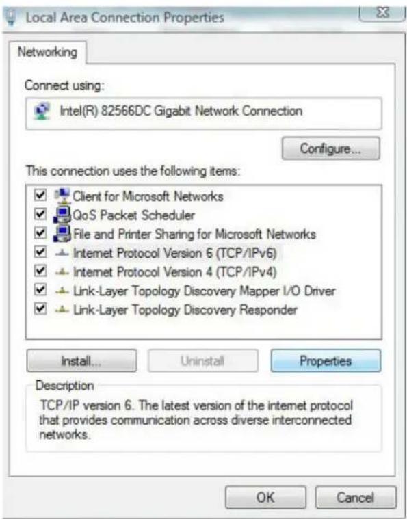
d) IntheInternetProtocolVersion4(TCP/IPv4) Propertiesdialogbox thatappears, settheIPaddressandsubnetmaskofthecomputer. (SeeTable3-1forthedetailedvalues).

e) ClicktheOKbuttontosavetheconfiguration.
TheoperationsontheWindowsXPoperatingsystemareasfollows:
a) IntheWindowstaskbar, selectStart → ControlPanel. Double-click NetworkConnectiontoenterthenetworkconnectionwindow.
b) Right-click Local Connection and select Properties from the shortcut menutobringuptheLocalConnectionPropertiesdialogbox.
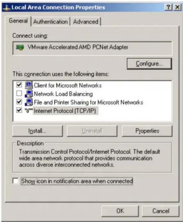
c) Double-click Internet Protocol (TCP/IP). In the Internet Protocol (TCP/IP) Properties dialog box that appears, set the Paddress and subnet mask of the computer. (See Table 3-1 for the detailed values).

d) ClicktheOKbuttontosavetheconfiguration.
2.Enterhttp://192.168.1.1(defaultmanagementIPaddressoftheONT)inthebrowseraddressbarofthecomputer,andpresstheEnterkeytobringuptheuserlogindialogbox.
3.Entertheadministratorusernameandpasswordinthelogindialogbox.Access theWebGUIafterthepassworddisauthenticated.

Caution:
Thesystemwilllogoutautomaticallyifnooperationisperformedinfive minutes.
WebConfigurationGUILayout
TheWebconfigurationGUIcomprisesthreeparts,asshowninFigure3-1.
◆ Navigationbar.Clickthelinktoenterthecorrespondingconfiguration managementpage.
◆ Linkbar.Clickthelinktoenterthesub-pageforcorrespondingconfiguration management.
◆Configurationmanagementarea.Displaysthecontentsoftheselected navigationbarandlinkbar.

(1)Navigationbar(2)Linkbar(3)Configurationmanagementarea
Figure3-1WebConfigurationGUI

Note:
Thescreenshotsprovidedhereareforreferenceonly,andtheactual WebGUIsfortheequipmentshallprevail.
The configuration GUI for the administrator is different from that for common users:
◆The administratorcanviewandconfigureallthenodeitemsintheWebGUI.
◆Thecommonuserscanviewandconfigureonlypartofthenodeitems. The followingliststhekeynodesavailableforcommonusers. Theconfiguration itemsactuallyavailableintheWebGUIforcommonusersshallprevail.
TheStatustab.
▶ User Account and Device Reboot in the Management tab.
3.2Status
The following introduces how to view basic information about the ONT, including the device information, WAN sidestatus, LAN sidestatus, optical power status and voice status, etc.
3.2.1 DeviceInformation
Select Status in the navigation bar, and select Device Information→Device Informationintheleftlinkbartoviewtheinformationsuchasthesoftwareversion, hardwareversion,devicemodelanddevicedescription.SeeFigure3-2.
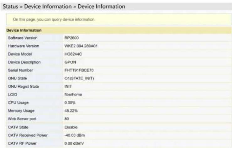
Figure3-2DeviceInformation
3.2.2 Wireless Network Status
Viewtheinformationaboutthewirelessnetwork,suchasnetworkmode,frequency channel,SSID,countofwirelesspackets,andlistofWi-Ficlients.
3.2.2.1 Wireless Network Status
Select Status in the navigation bar, and then select Wireless Status→Wireless Statusintheleftlinkbartoviewtheinformationofthewirelessnetwork,suchas networkmode,band,SSIDandwirelesspacketstatistics,asshowninFigure3-3.

Figure3-3WirelessNetworkStatus
3.2.2.2Wi-FiUserList
Select Status in the navigation bar, and then select Wireless Status→WIFI Clients ListintheleftlinkbartoviewthelistofclientendsconnectedtotheONTwireless network,asshowninFigure3-4.

Figure3-4WIFIUserList
3.2.3WANSideStatus
Select Status in the navigation bar and select Wan Status→Wan Status in the left linkbartoviewtheinformationsuchasthestatus,IPobtainingmode,IPaddress andsubnetmaskoftheWANinterface.SeeFigure3-5.
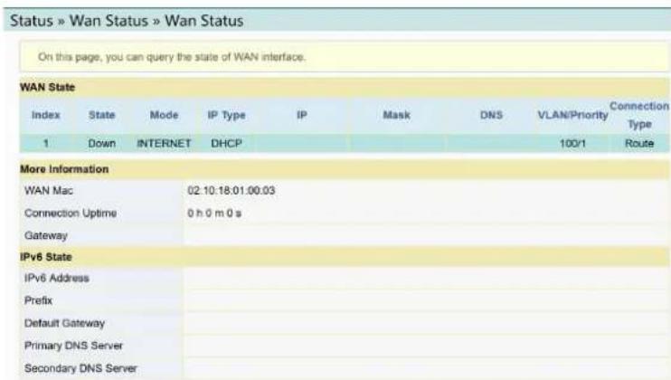
Figure3-5WANSideStatus
3.2.4 LANSideStatus
CheckthestatusinformationabouttheLANinterfaceandtheDHCPclientend.
3.2.4.1 LANSideStatus
Select Status in the navigation bar and select Lan Status→Lan Status in the left linkbartoviewtheinformationsuchastheIPaddress,subnetmaskoftheLANside. SeeFigure3-6.

Figure3-6LANSideStatus
3.2.4.2DHCPUserList
Select Status in the navigation bar and select Lan Status→DHCP Clients List in the left linkbart view the information about the DHCP client ends such as the IP address, MACaddressandhiredtime. See Figure 3-7.

Figure3-7DHCPUUserList
3.2.5 Optical Power Status
Select Status in the navigation bar and select Optical Info→Optical Info in the left linkbartoviewtheopticalmoduleinformationsuchastheTxopticalpower,Rx opticalpowerandworkingtemperature.SeeFigure3-8.
| On this page, you can query state of optical power. | |
| Optical Info | |
| Transmitted Power | 2.49 dBm |
| Received Power | -12.50 dBm |
| Operating Temperature | 34.69 ℃ |
| Supply Voltage | 3.40 V |
| Bias Current | 12.90 mA |
Figure3-8OpticalPowerStatus
3.2.6VoiceStatus
Select Status in the navigation bar and select VoIP Status→VoIP Status in the left linkbartoviewtheinformationsuchastheportstateandthetelephonenumber. SeeFigure3-9.

Figure3-9VoiceStatus
3.3Network
The following introduces how to configure the LAN, broadband, DHCP server, authentication and voice configuration in the WebGUI.
3.3.1WLANSettings
ThissectionintroduceshowtoconfigureWi-FicontrolandWPSaswellasbasic andadvancedparametersofthewirelessnetworkontheWebpage.
3.3.1.1 BasicParameters
Configure the parameters of the 2.4G wireless networks such as the switch, network mode, domain, frequency bandwidth and frequency channel.
- Select Network in the navigation bar and select Wlan Settings→Basic in the leftlinkbartoopenthebasicsettingpageforthe2.4Gwirelessaccessservice, asshowninFigure3-10.

Figure3-10BasicParametersoftheWirelessNetwork
-
Configurethebasicparametersofthe2.4Gwirelessnetwork.Fordetailsofthe parameters,seeTable3-2.
-
ClickApplytosaveandapplytheconfiguration.
Table3-2BasicParametersofthe2.4GWirelessNetwork
| Item | Description |
| RadioON/OFF | EnablesordisabletheWLANservice.RADIOON:thewirelessnetworkis enabled;RADIOOFF:thewirelessnetworkisdisabled. |
| NetworkMode | Themodesupportedbythewirelessnetwork.Theoptionsinclude802.11b, 802.11g,802.11b/g,802.11nand802.11b/g/n.Thedefaultsettingis802.11b/g/n. |
| Domain | Selectyourregion. |
| Frequency Bandwidth | Thewidthofwirelessband.Theoptionsinclude20MHz/40MHz,20MHz and40MHz. |
| Frequency (Channel) | Thechannelusedforcommunicationbetweenthewirelessaccesspoint andthewirelessstation.TheoptionsincludesAutoSelectandChannel1 toChannel13.ThedefaultsettingisAutoSelect. |
| GuardInterval | The wireless protection interval. The options includeShortandLong. The defaultsettingisShort. |
3.3.1.2 AdvancedConfiguration
Configure the parameters of the 2.4G wireless network, such as the SSID, password, security mode and algorithm.
- Select Network in the navigation bar, and then select Wlan Settings→ Advancedintheleftlinkbartoopentheadadvancedsettingpageforthe2.4G wirelessaccessservice,asshowninFigure3-11.

Figure3-11 AdvancedSettingsoftheWirelessNetwork
-
Configuretheparametersofthe2.4Gwirelessnetwork,suchastheSSID, password,securitymodeandalgorithm.Fordetailsoftheparameters,see Table3-3.
-
ClickApplytosaveandapplytheconfiguration.
Table3-3AdvancedSettingParametersofWirelessNetwork
| Item | Description | |
| SSIDChoice | SelecttheSSID.Thevaluerangeis1to4. | |
| Enable/Disable | EnablesordisablesthecorrespondingSSID. | |
| SSIDName | Thewirelessnetworkname,usedtoidentifydifferentwirelessnetworks. | |
| Hidden | SelectwhethertohidetheSSID.WhentheSSIDishidden,thewireless terminalcannotdetectthewirelesssignalsunlesstheSSIDisentered. | |
| SecurityMode | Theauthenticationmodeforthewirelessterminalrequiringaccesstothe wirelessnetwork.TheoptionsincludeOPEN,SHARED,WEPAUTO,WPA-PSK,WPA2-PSKandWPAPSKWPA2PSK.◆OPEN:Unencrypted.Anyterminalcanaccessthewirelessnetwork;therefore,thesecuritycannotbeguaranteed.Thismodeisnot advisable.◆SHARED:ThismodeisbasedontheWEPencryptionprotocol,where thesamekeyisconfiguredforthewirelessaccessclientend and equipmentsidetoprovidethesamesecuritylevelasthewiredLAN.Itis atraditionalWLANsecurityprotocol.◆WEPAUTO:BothOPENWEPandSHAREDWEParesupported.◆WPA-PSK:ThismodeisbasedontheWLANsecurityprotocol,where a keyispre-configuredforthewirelessaccessclientend.Theequipment sideauthenticatesthelegalityofthewirelessaccessclientendkeyby the4-wayhandshakekeyagreementprotocol.Thisprovidesasaferand moreconfidentialwirelessnetworkservicethanWEP.◆WPA2-PSK:WPA2isthesecondeditionofWPA.◆WPAPSKWPA2PSK:theauthenticationmodecombiningWPAand WPA2. | |
| WPA Algorithms | TheencryptionalgorithmsincludeTKIP,AESand TKIPAES. | Thisitemshouldbe configuredifthe authenticationmode isWPA-PSK,WPA2-PSKor WPAPSKW-PA2PSK. |
| PassPhrase | EntertheSSIDkey. | |
| EncryptType | SelecttoenableordisabletheWEPencryptionwhenthenetwork authenticationmodeisOPEN. | |
| DefaultKey | SelectKey1toKey4;thatis,selectoneofthefour configurednetworkkeys. | Thisitemshouldbe configuredwhenthe authenticationmode isOPENandthe WEPencryptionis enabledorthe authenticationmode isSHAREDor WEPAUTO. |
| WEPKey1to WEPKey4 | Enterthekeyvalueandselectthekeyvaluetype.At leastentertheitemselectedinDefaultKey.◆IfASCIIisselected,youshouldenterakeyvalue containing5to13characters.◆IfHexisselected,youshouldentera hexadecimalfigurecontaining10to26 characters. | |

Note:
PressingtheApplybuttonwillvalidateasingleSSIDchoice
configurationitem.IfyoudonotclickApplyaftermodifyingtheSSID1
setting, themodificationwillnottakeeffect.
If the SSID1 setting is modified, the factory default wireless network account will be invalid.
If you forget the customized wireless network account, restore the factory default account by pressing down the Reset button form more than 5 seconds.
3.3.1.3Wi-FiControl
Configureparametersofthe2.4Gwirelessnetwork,suchasWi-Fipowerand numberofWIFIconnections.
- Select Network in the navigation bar, and then select Wlan Settings→WIFI ControlintheleftlinkbartoopentheWIFIcontrolsettingpageforthe2.4G wirelessaccessservice,asshowninFigure3-12.

Figure3-12WIFIControl
- Configureparametersofthe2.4Gwirelessnetwork,suchasWIFIpowerand numberofWIFIconnections.Fordetailsoftheparameters,seeTable3-4.
- ClickApplytosaveandapplytheconfiguration.
Table3-4ParametersofWIFIControl
| Item | Description |
| WIFIPowerControl | Thetransmitpowerofthewirelesssignal.Alargervalue indicatesawidersignalcoverage. |
| NumberofWIFI Connections | ThemaximumnumberofclientendssupportedbytheSSIDs. |
3.3.1.4WPSSConfiguration
WPScanautomaticallysetthewirelessnetworkname(SSID)andwireless encryptionkeyfortheHG6244CandclientendsupportingtheWi-Fiservice.You needonlytopressdowntheWPSbuttonorenterthePINtoachievesafe connection.Sinceyouneednotrememberthelongencryptionkey,youarefreeof thetroublecausedbyforgettingthepassword.
- Select Network in the navigation bar and select Wlan Settings WPS in the leftlinkbartoopentheWPSsettingspage,asshowninFigure3-13.
Figure3-13WPSCustomuration

-
SelectwhetheronenabletheWPSfunction. TheoptionsincludeEnableandDisable.
-
SelecttheWPSconnectionmodeasrequired.
▶ Select Please input PIN code., and enter the PIN code of the client end in thePINtextbox.ThenclickConnect.
Select Please turn on the button of the equipment and press down the WPSbuttonontheONT.ThenpressdowntheWPSbuttonortheWPS softwarekeyontheclientend.
- Wait until the connection is completed.
3.3.2 LAN Settings
ConfigurethemanagementIPaddressandsubnetmaskattheLANside.
- Select Network in the navigation bar and select LAN Settings→LAN Settings intheleftlinkbartoopentheLANsettingspage,asshowninFigure3-14.

Figure3-14LANSettings
-
ConfigurethemanagementIPaddressandsubnetmaskattheLANside.See Table3-5fortheparameterdescription.
-
ClickApplytosaveandapplytheconfiguration.
Table3-5ParametersofLANSettings
| ItemDescription | |
| GatewayIP address | ThemanagementIPaddressattheLANsideoftheONT. Thedefaultvalue is192.168.1.1. |
| SubnetMask | ThesubnetmaskoftheONTfortheLAN. Thedefaultvalueis255.255. 255.0. |
| IPv6/Prefix | TheIPv6gatewayaddress,includingaprefixof64bits. Thedefaultvalue isfe80::1/64. |
| ManagedFlag | SelectwhetherodistributetheIPv6addressbasedonDHCP. Thedefault valueisDisable. |
| OtherConfig Flag | SelectwhetherodistributetheIPv6DNSinformationbasedonDHCP. The defaultvalueisEnable. |
| MaxRAinterval | Themaximumintervalforannouncingthegatewayinformation. Thedefault valueis10. |
| MinRAinterval | Theminimumintervalforannouncingthegatewayinformation. Thedefault valueis5. |
| DNSsource | ThesourceoftheDNSdistributedtoPC,includingWANconnection,ONTproxyandstaticconfiguration.ThedefaultvalueisWANconnection. |
| Prefixmode | ThesourceoftheprefixinformationdistributedtoPC,includingWANconnectionandstaticconfiguration.ThedefaultvalueisWANconnection. |
| EnableDHCP6S | SetswhethertoenabletheDHCPv6server.ThisitemshouldbeselectedifManagedFlagorOtherConfigFlagisselected;otherwisetheIPaddressorDNSinformationcannotbedistributed.Enabledbydefault. |
| StartIPv6Address | ThestartingaddressIDoftheaddresspoolfordistributionofDHCPv6IPaddresses.Thedefaultvalueis0:0:0:2. |
| EndIPv6Address | TheendingaddressIDoftheaddresspoolfordistributionofDHCPv6IPaddresses.Thedefaultvalueis0:0:0:255. |
3.3.3 Broadband Settings
SelectdifferentWANconnectionsfordifferentnetworkenvironment,orconfigure correspondingparametersfortheselectedWANconnection.
- Select Network in the navigation bar and select BroadBand Settings→InternetSettingsintheleftlinkbartoopentheInternetsettingspage,as showninFigure3-15.
| WAN List | |||
| WAN Name | VID/Priority | WAN IP Mode | |
| INTERNET_R_VID_100 | 100/1 | DHCP | ☐ |
| Service Type | INTERNET | ||
| Connection Type | Route | ||
| VLAN ID | 100 | * (1-4094) | |
| Priority | 1 | * (0-7) | |
| NAT | Enable | ||
| DNS Relay | Enable | ||
| MTU | 1500 | * (1280-1500) | |
| LAN Binding | LAN 1 ☑ LAN 2 ☑ LAN 3 ☐ LAN 4 ☐ | ||
| 2.4G SSID Binding | SSID 1 ☑ SSID 2 ☐ SSID 3 ☐ SSID 4 ☐ | ||
| 5G SSID Binding | SSID 1 ☐ SSID 2 ☐ SSID 3 ☐ SSID 4 ☐ | ||
| IP Mode | IPv4 | ||
| WAN IP Mode | DHCP | ||
| DHCP Mode | |||
| IP Address | |||
| Subnet Mask | |||
| Default Gateway | |||
| Primary DNS Server | |||
| Secondary DNS Server | |||
Figure3-15InternetSettings
- ConfigureparametersrelevanttotheInternetattheWANside.Table3-6 introducestheparameters.
- ClickApplytosaveandapplytheconfiguration.
Table3-6 Parameters for Internet Settings
| Item | Description | |
| ServiceType | SelecttheWANportservicetype.◆TR069:thisconnectionisonlyapplicableforTR069.◆INTERNET:thisconnectionisonlyapplicableforInternetaccess.◆TR069_INTERNET:thisconnectionisapplicableforbothTR069andInternetaccess.◆VOIP:thisconnectionisonlyapplicableforvoiceapplication.◆VOIP_INTERNET:thisconnectionisapplicableforvoiceandInternetaccess.◆OTHER:otherconnections. | |
| ConnectionType | SelecttheconnectiontypeoftheWANport.◆Bridge:theLayer2bridgeconnectionmode.ThisconnectionmodecanbeusedwhentheservicetypeissettoINTERNET,IPTVorOTHER.◆Route:theLayer3routerconnectionmode.ThisconnectionmodecanbeusedwhentheservicetypeissettoINTERNET,IPTVorOTHER. | |
| VLANID | SetstheVLANIDoftheWANconnection.Thevaluerangesfrom1to4094.TheVLANIDvaluehereshouldbeconsistentwiththatontheusersideoftheOLT. | |
| PrioritySetsthepriorityoftheVLAN.Thevaluerangesfrom0to7. | ||
| NATEnablesordisable | estheNATfunction. | ◆UsersneedtoconfigurethisitemwhentheservicetypeissettoTR069_INTERNETorVOIP_INTERNET.◆UsersneedtoconfigurethisitemwhentheservicetypeissettoINTERNETorOTHERandtheconnectiontypeissettoRoute. |
| DNSRelayEnablesordisable | disabletheDNSrelayfunction. | |
| MTU | Enterthemaximumtransmissionunit.Itisadvisedtousethedefaultvalue. | |
| LANBindingSelectthe | LANporttobeboundwiththeWANport. | |
| 2.4GSSIDBinding | Selectthewireless2.4GSSIDtobeboundwiththeWANport. | |
| IPMode | TheoptionsincludeIPv4&IPv6,IPv4andIPv6. | ◆UsersneedtoconfigurethisitemwhentheservicetypeissettoTR069_INTERNETorVOIP_INTERNET.◆UsersneedtoconfigurethisitemwhentheservicetypeissettoINTERNETorOTHERandtheconnectiontypeissettoRoute. |
| WANIPMode | SetstheIPaddressobtainingmodeattheWANsideoftheONT.TheoptionsincludeDHCP,staticandPPPoE.◆DHCP:ObtainingthelPaddressdynamically.◆Static:SettingthelPaddressinastaticmode.◆PPPoE:PPPoEdialingmode. | Thisitemshouldbesetifthe connectiontypeisRoute. |
| UserName | EntertheusernameprovidedbyISP. | Thisitemshouldbesetifthe WANIPModeissettoPPPoE. |
| Password | EnterthepasswordprovidedbyISP. | |
| OperationMode | SetsthePPPoEconnectionmode.Thedefaultsettingis "KeepAlive". | |
| IPAddress | EnterthestaticIPaddressattheWANsideprovidedbyISP. | Thisitemshouldbesetwhen theIPModeissettoIPv4&IPv6orIPv4andthe WANIPModeissettostatic. |
| SubnetMask | EnterthesubnetmaskprovidedbyISP. | |
| DefaultGatewayEnter | thedefaultgatewayprovidedbyISP. | |
| PrimaryDNS Server | EntertheIPaddresssofttheactiveDNSserverprovidedby ISP. | |
| SecondaryDNS Server | EntertheIPaddresssoftthestandbyDNSserverprovidedby ISP. | |
| IPv6Address | EnterthestaticIPv6addressattheWANsideprovidedby ISP. | Thisitemshouldbesetwhen theIPModeissetto IPv4&IPv6orIPv6andthe WANIPModeissettostatic. |
| IPv6PrefixLength | EnterthestaticIPv6addressprefixlengththattheWANside providedbyISP. | |
| DefaultGatewayEnter | thedefaultgatewayprovidedbyISP. | |
| PrimaryDNS Server | EntertheIPaddresssofttheactiveDNSserverprovidedby ISP. | |
| SecondaryDNS Server | EntertheIPaddresssoftthestandbyDNSserverprovidedby ISP. | |
| IPv6Address Mode/IPv6Prefix Mode | SelecttheIPv6addressobtainingmode/prefixobtaining mode. | Thisitemshouldbesetwhen theIPModeissetto IPv4&IPv6orIPv6andthe WANIPModeissettoDHCP orPPPoE. |
3.3.4DHCPServer
UsingtheDHCPfunction,theONTcandistributethenetworkparameters(suchasIPaddress,gatewayandDNSserverIPaddress)tothedevices(suchascomputer) withintheLAN.UserscanmanagetheIPaddressescollectivelyusingthisfunction.
- Select Network in the navigation bar, and then select DHCP Server→DHCP ServicefromtheleftlinkbartoopentheDHCPserverconfigurationpage, as showninFigure3-16.
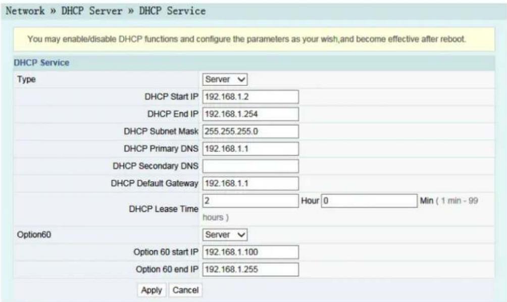
Figure3-16DHCPService
- ConfiguretheDHCPserverparametersasrequired.Table3-7describesthe parameters.
- ClickApplytosavetheconfigurationinformation. The configuration will take effectaftertheONTisrebooted.
Table3-7ParametersfortheDHCPServer
| Item | Description | |
| Type | EnablesordisabletheDHCPserver.◆Server:EnablestheDHCPserver.TheONTcandynamicallydistributelPaddressestouserterminals.◆Disable:TheuserterminalsconnectedtotheONTcannotobtaintheprivatenetworkIPaddressusingtheDHCP. | |
| DHCPStartIP | ThestartingIPaddresssofthelPaddresspoolfortheactiveDHCPserver. | Note:TheIPaddresssetheshouldbeinthesamenetworksegmentwiththelPaddresssetinLANSettings;otherwise,theDHCPserverwillnotoperatenormally. |
| DHCPEndIP | TheendingIPaddresssofthelPaddresspoolfortheDHCPserver. | |
| DHCPSubnetMaskThemaskoftheactiveDHCPserver. | ||
| DHCPPprimaryDNS | TheIPaddresssoftheactiveDNSserver. | |
| DHCPSecondaryDNS | TheIPaddressofthestandbyDNSserver. | |
| DHCPDefaultGateway | ThedefaultgatewayoftheactiveDHCPserver. | |
| DHCPLeaseTime | TheleasetimeoftheIPaddresspooloftheDHCPserver. | |
| Option60EnablesordisabletheOption60propertytoidentifytheuserterminal. | ||
| Option60startIP | ThestartingIPaddressofthenetworksegmentdistributedtotheOption60propertyterminalbytheDHCPserver. | ThisitemshouldbeconfiguredwhentheOption60fieldoftheDHCPserverisenabled. |
| Option60endIP | TheendingIPaddressofthenetworksegmentdistributedtotheOption60propertyterminalbytheDHCPserver. | |
3.3.5 AuthenticationSetting
Configure the parameters relevant to the ONT authentication mode, so that the ONT can pass the OLT authentication.
- Select Network in the navigation bar and select Authentication→OLT AuthenticationintheleftlinkbartoopentheOLTauthenticationconfiguration page,asshowninFigure3-17.

Figure3-17OLTAuthentication
-
Configuretheparametersasrequired.Table 3-8 describestheparameters.
-
ClickApplytosavetheconfigurationinformation. The configuration will take effectaftertheONTisrebooted.
Table3-8ParametersforOLTAuthentication
| Item | Description | |
| LOIDSetstheLOIDusername. Thisitemisconfigurable | whentheONTusestheLOIDauthenticationmode. | |
| LogicPasswordSetstheLOIDpassword. | ||
| PasswordAuth | SetstheauthenticationpasswordwhentheONTisauthenticatedbypassword. | |
3.3.6VoiceConfiguration
Thissectionintroduceshowtoconfigurethekeyparameters,basicparameters,advancedsettings,digitmapandtimelength,andcodingmodeforvoiceservicesintheWebpage.
3.3.6.1KeyParameters
Configure the parameters such as VoIP protocol type and VoIP port.
- Select Network in the navigation bar and select VoIP Settings→Key ParametersfromthelinkbarontheleftsidetoopentheVoIPkeyparameter page,asshowninFigure3-18.

Figure3-18 KeyParametersforVoiceConfiguration
-
Configure the key VoIP parameters as required. Table 3-9 describes the parameters.
-
ClickApplytosaveandapplytheconfiguration.
Table3-9KeyParametersforVoiceService
| Item | Description |
| VoIPProtocol | Thevoiceprotocoltype.TheoptionsincludeSIPandH.248.Thedefault settingisSIP. |
| Port | EnableordisabletheVoIPport. |
3.3.6.2 Basic Parameters
ConfigurebasicVolPparameters.
- Select Network in the navigation bar and select VoIP Settings→Basic from thelinkbarontheleftsidetoopentheVoIPbasicparameterconfigurationpage, asshowninFigure3-19.
- Select Network in the navigation bar and select VoIP Settings→Advanced in the left link bartoopenthead advanced VoIP setting page, as shown in Figure 3-20.

Figure3-20AdvancedParametersforVoiceConfiguration
- ConfiguretheadadvancedVoIPparametersasrequired.Table3-11describes theparameters.
- ClickApplytosaveandapplytheconfiguration.
Table3-11 Advanced Parameters for Voice Service
| Item | Description |
| RFC2833PT Value | DefaultPTvalueinRFC2833.Thevaluesinclude0and96to127. |
| RFC2198PT Value | DefaultPTvalueinRFC2198.Thevaluesinclude0and96to127. |
| AliveTimes | Heartbeattimeouttimes.Thevaluerangesfrom1to120. |
| AliveInterval | Heartbeattimelength.Thevaluerangesfrom1to43200. |
| FaxMode | Thefaxmode.Theoptionsinclude"Transparent"and"T38".Thedefault settingis"Transparent". |
| ReversedPolarity | Enableordisablethereversedpolaritysignal.Thedefaultsettingis "Enable". |
| CharacterEscape Mode | Theoptionsinclude"Escape"and"NotEscape".Thedefaultsettingis "Escape". |
| DTMFMode | TheDTMFmode.Theoptionsinclude"Transparent"and"RFC2833".The defaultsettingis"Transparent". |
| Caller-IDHead Field | TheCallerIDdisplaymode.Theoptionsinclude"Fromdomain"and"P- assertedId".Thedefaultsettingis"P-assertedId". |
| KeepaliveModeEnableorDisabletheheartbeatmode.Thedefaultsettingis"Active". | |
| LocalPort | Thenumberofthelocalport.Valuerange:1024to65535.Thedefault settingis5060. |
| EchoCancel | Enableordisabletheechosuppression.Thedefaultsettingis"Enable". |
| Silence Suppression | Enableordisablethesilencesuppression.ThedefaultsettingisDisable. |
| Call-waitingEnableordisablethecall-waitingfunction.ThedefaultsettingisDisable. | |
| CallConference | Enableordisablethecallconference.ThedefaultsettingisDisable. |
| CallerIDMode | Theoptionsinclude"FSK"and"Disable".Thedefaultsettingis"FSK". |
| OutputGainOutputgain. | Thevaluerangesfrom-12to6. |
| InputGainInputgain. | Thevaluerangesfrom-12to6. |
3.3.6.4 DigitmapandLength
ConfiguretheVolPtimelengthanddigitmapparametersincludingdigitmap matchingmode,SIPregistrationcycle,shorttimer,longtimer,startingtimerand longcalltimer,etc.
- Select Network in the navigation bar and select VoIP Settings→Dial and Timeoutfromthelinkbarontheleftsidetoopenthedialandtimeout configurationpage,asshowninFigure3-21.
![Network » VoIP Settings » Dial and Timeout On this page, you can config VoIP timer and logplot. VoIP Timer Param Logplot Mode Min Logplot [0-9ABCD].[/*#][0-9ABCD*#]. Regist Period 3600 120~65535(s) Short Digit Timer 4 1~254(s) Long Digit Timer 10 1~254(s) Start Digit Timer 60 1~254(s) Long Call Time 60 1~254(s) Hang Up Time 60 1~254(s) Busy Time 40 1~254(s) Retransmission Interval 30 1~3600(s) Avalanche Timer 30 1~254(s) Sliding Spring Time 90 - 600 90~2500(ms), multiple of 10 Apply Cancel](/content/2026/06/1359203/images/0414108dcf00f0ba99e21a9f1a564ca3fe9d194b5355d0faa3b03f9bbca1e7aa.jpg)
Figure3-21DigitmapandLength
- ConfigureVoIPtimelengthparameters.Table3-12 describestheparameters.
- ClickApplytosaveandapplytheconfiguration.
Table3-12ParametersofDigitmapandLength
| Item | Description |
| LogplotMode | Digitmapmatchingmode.TheoptionsincludeMaxandMin.Thedefault settingisMin. |
| RegistPeriod | TheSIPregistrationperiod.Thevaluerangesfrom120to65535(s).The defaultsettingis3600. |
| ShortDigitTimerTheshorttimer.Thevaluerangesfrom1to254(s).Thedefaultsettingis4. | |
| LongDigitTimer | Thelongtimer.Thevaluerangesfrom1to254(s).Thedefaultsettingis 10. |
| StartDigitTimer | Thestartingtimer.Thevaluerangesfrom1to254(s).Thedefaultsettingis 60. |
| LongCallTime | Thetimerforlongcallwithoutresponse.Thevaluerangesfrom1to254 (s).Thedefaultsettingis60. |
| HangUpTime | Thehowlertonetimer.Thevaluerangesfrom1to254(s).Thedefault settingis60. |
| BusyTime | Thebusytonetimer.Thevaluerangesfrom1to254(s).Thedefaultsetting is40. |
| Retransmission Interval | Theintervalforretransmissionofregistrationinformation.Thevalueranges from1to3600(s).Thedefaultsettingis30. |
| AvalancheTimer | Theavalanchetimer.Thevaluerangesfrom1to254(s).Thedefault settingis30. |
| SlidingSpring Time | TheslidingspringtimeThevaluerangesfrom90to2500(ms)andshould bemultiplesof10.Thedefaultvaluerangesfrom90to600. |
3.3.6.5Coding
Configurecodingpriorityforvoiceports. The parameters include priority, coding mode, RTPpacketization period, and soon.
- Select Network in the navigation bar and select VoIP Settings→Coding from thelinkbarontheleftsidetoopenthecodingconfigurationpage,asshownin Figure3-22.

Figure3-22Coding
- Configureparametersofvoiceports, includingpriority,codingmodeandRTP packetizationperiod,asshowninTable3-13.
- ClickApplytosaveandapplytheconfiguration.
Table3-13CodingParameters
| Item | Description |
| Mode | Thecodingmode.TheoptionsincludeG.711MuLaw,G.711ALaw,G.723.1,G.729andG.722. |
| Packetization Period | TheRTPpacketizationperiod.Thevaluerangesfrom10to60(ms). |
3.4 Security
The following introduces how to configure the firewall, remote control, dynamic DoS and HTTPS in the WebGUI.
3.4.1 Firewall
Thefirewallconfigurationincludes
◆FirewallControl
◆IPv4Filtering
◆IPv6Filtering
◆URLFiltering
◆DHCPFiltering
◆Anti-portScan
◆ MACFiltering
◆IPv6MACFiltering
Enabling the firewall can prevent malicious access to the WAN port of the ONT.
- Select Security in the navigation bar and select Firewall→Firewall Control in the left link bartoopenthe firewallenabling page, asshownin Figure 3-23.

Figure3-23FirewallEnabling
- SelecttoEnableorDisablethefirewallasrequired.
- ClickApplytosaveandapplytheconfiguration.
3.4.1.2IPFiltering
AlloworforbidtheincomingoroutgoingflowoftheIPpacketsthatcomplywiththe filteringconditions. Afterthefirewallisenabled, thepre-setruleswilltakeeffect.
- Select Security in the navigation bar and select Firewall→IPv4 Filtering in the leftlinkbar.ClickAddtoopenthefilteringrulelistconfigurationpage,asshown inFigure3-24.
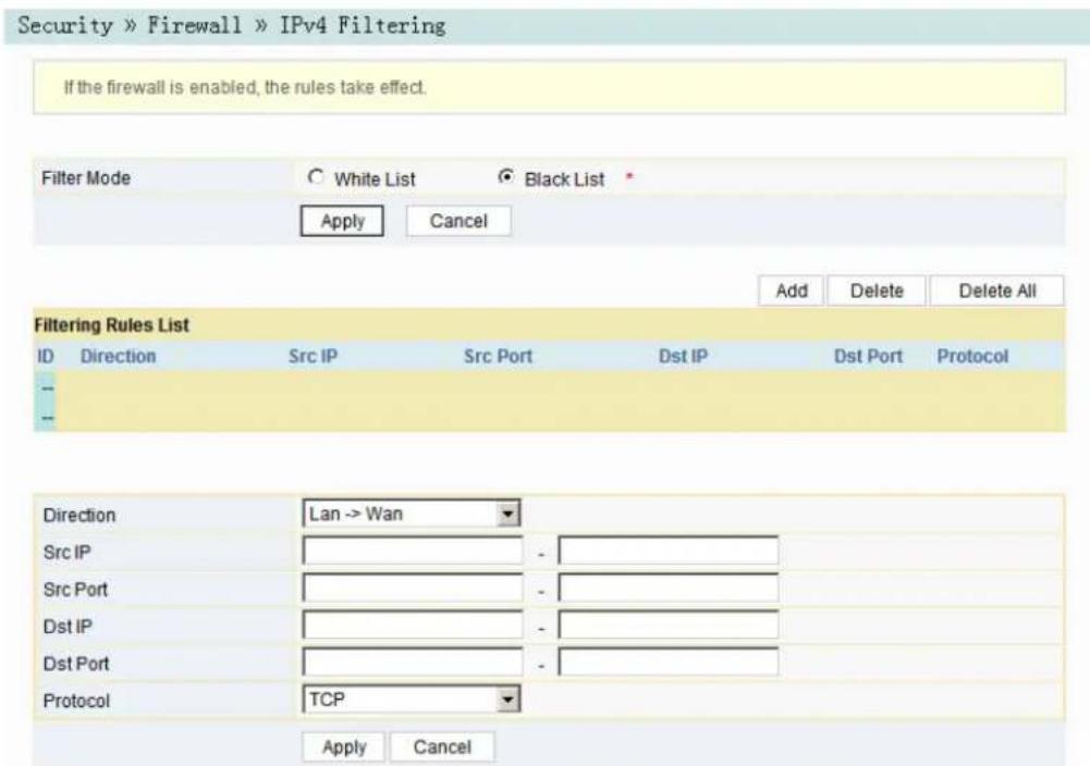
Figure3-24IPv4Filtering
- Configuretheparametersrelevanttofilteringasrequired.Table3-14describes theparameters.
- ClickApplytosaveandapplytheconfiguration.
Table3-14ParametersforIPAddressFiltering
| Item | Description | |
| FilterMode | Selectthefilteringmode.◆Whitelistindicatesthatthedatacomplyingwiththerulesinthe filteringruletablewillbeallowedtopass.◆Blacklistindicatesthatthedatacomplyingwiththerulesinthe filteringruletablewillnotbeallowedtopass. | Aftertheaforesaid operation,clicktheApplybuttontovalidate theconfiguration. |
| Direction | Setsthedirectionofthefilteringrule.◆LAN->WAN:uplinkdirection.◆WAN->LAN:downlinkdirection. | |
| SrcIP | EnterthelPaddressattheLANsideifthedirectionisLAN->WAN.EnterthelPaddressattheWANsideifthedirectionisWAN->LAN. | |
| SrcPort | TheportrangeofthesourceIPaddress.ThisitemisconfigurablewhentheProtocolissetto TCPorUDP. | |
| DstIP | EnterthelPaddressattheWANsideifthedirectionisLAN->WAN.EnterthelPaddressattheLANsideifthedirectionisWAN->LAN. | |
| DstPort | TheportrangeofthedestinationIPaddress.ThisitemisconfigurablewhentheProtocolis settoTCPorUDP. | |
| Protocol | Protocoltype,includingTCP,UDP,ICMPandALL. | |
- Configure the parameters relevant to filtering as required. Table 3-15 describes the parameters.
3. ClickApplytosaveandapplytheconfiguration.
Table3-15ParametersofIPv6Filtering
| Item | Description | |
| Uplink | Selecttheuplinkfilteringmode.◆Whitelistindicatesthatthedatacomplyingwiththerulesinthefilteringruletablewillbeallowedtopass.◆Blacklistindicatesthatthedatacomplyingwiththerulesinthefilteringruletablewillnotbeallowedtopass. | Aftertheaforesaid operation,clicktheApplybuttontoto validate the configuration. |
| Downlink | Selectthedownlinkfilteringmode.◆Whitelistindicatesthatthedatacomplyingwiththerulesinthefilteringruletablewillbeallowedtopass.◆Blacklistindicatesthatthedatacomplyingwiththerulesinthefilteringruletablewillnotbeallowedtopass. | |
| Direction | Setsthedirectionofthefilteringrule.◆LAN->WAN:uplinkdirection.◆WAN->LAN:downlinkdirection. | |
| SrcIPv6 | EntertheIPv6addressattheLANsideifthedirectionissettoLAN->WAN.EntertheIPv6addressattheWANsideifthedirectionissettoWAN->LAN. | |
| SrcPort | TheportrangeofthesourceIPaddress.ThisitemisconfigurablewhentheProtocolissettoTCPorUDP. | |
| DstIPv6 | EntertheIPv6addressattheWANsideifthedirectionissettoLAN->WAN.EntertheIPv6addressattheLANsideifthedirectionissettoWAN->LAN. | |
| DstPort | TheportrangeofthedestinationIPaddress.ThisitemisconfigurablewhentheProtocolissettoTCPorUDP. | |
| Protocol | Protocoltype,includingTCP,UDP,ICMPandALL. | |
3.4.1.4URLFiltering
BysettingtheURLfilteringrules, userscanforbidorallowallthedatapacketssent toorreceivedfromacertainIPaddress. Afterthefirewallisenabled, thepre-set URLfilteringrulewilltakeeffect, andthedomainnamesthatmeetthefiltering conditionswillbefiltered.
- Select Security in the navigation bar and select Firewall→URL Filtering in the leftlinkbar, and then click Addto open the URL filtering table configuration page, as shown in Figure 3-26.
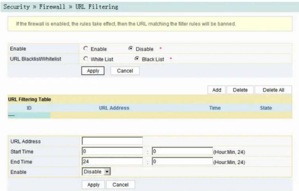
Figure3-26URLFiltering
- Configuretheparametersrelevanttofilteringasrequired.Table3-16describes theparameters.
- ClickApplytosaveandapplytheconfiguration.
Table3-16ParametersforURLFilteringParameters
| Item | Description | |
| Enable | EnablesordisabletheURLfilteringfunction. | Aftersetting,clickApplybelowtotakeeffect. |
| URLBlacklist/Whitelist | Selectthefilteringmode.Thewhitelistandblacklistmodesareconfiguredglobally,andcannotbeenabledsimultaneously.◆Whitelistindicatesthatthedatacomplyingwiththerulesdefinedinthefilteringruletablewillbeallowedtopass.◆Blacklistindicatesthatthedatacomplyingwiththerulesdefinedinthefilteringruletablewillnotbeallowedtopass. | |
| URLAddress | TheURLaddressaccessedbyusers. | |
| StartTime | Thestartingtimeofthefilteringrule. | |
| EndTime | Theendingtimeofthefilteringrule. | |
| Enable | Enablesordisablethisfilteringrule.TheoptionsincludeDisableand Enable. | |
3.4.1.5DHCPFiltering
ForbidorallowtheuserdeviceconfiguredwiththeMACaddresstoobtainanIP addressintheDHCPmodetopreventDOSattacks. Afterthefirewallisenabled, the pre-setruleswilltakeeffect.
- Select Security in the navigation bar and select Firewall→DHCP Filtering in the left link bar. Then click Add to open the DHCP Filtering Table configuration page, as shown in Figure 3-27.

Figure3-27DHCPFiltering
- Configure the parameters relevant to filtering as required. Table 3-17 describes the parameters.
- ClickApplytosaveandapplytheconfiguration.
Table3-17ParametersforDHCPFiltering
| Item | Description | |
| DHCPFiltering Enable | EnablesordisabletheDHCPfiltering. | Aftersetting,clickApplybelowto takeeffect. |
| DHCPFiltering Blacklist/ Whitelist | Selectthefilteringmode.Thewhitelistandblacklist modesareglobalconfiguration,whichcannotbe enabledsimultaneously.◆Whitelistindicatesallowingthedeviceconfigured withtheMACaddresstoobtainthelPaddress usingtheDHCP.◆Blacklistindicatesforbiddingthedevice configuredwiththeMACaddresstoobtainthelP addressusingtheDHCP. | |
| MACAddress | TheMACaddressoftheuserdevicesubjectttotheDHCPfilteringrule. | |
3.4.1.6 Anti-portScan
Enableordisabletheanti-portscanfunction.
- Select Security in the navigation bar and select Firewall→Anti Port Scan in the left link bartoopenthe anti-port scan page, asshownin Figure 3-28.

Figure3-28 Anti-port Scan
- Select to Enable or Disable the anti-port scan function as required.
- ClickApplytosaveandapplytheconfiguration.
3.4.1.7 MACAddressFiltering
OneuserdevicemayhavemultipleIPaddressesbutonlyoneMACaddress. The userdeviceaccessauthorityintheLANcanbecontrolledeffectivelybysetting the MACaddressfiltering. Afterthefirewallisenabled, thepre-setruleswilltakeeffect, andtheMACaddressesthatmeetthefilteringconditionswillbefiltered.
- Select Security in the navigation bar and select Firewall→MAC Filtering in theleftlinkbar, and thenclickAddtoopentheMACaddressfilteringtable configurationpage, asshowninFigure3-29.

Figure3-29MACFiltering
- Configureparametersrelevanttofilteringasrequired.Table3-18describesthe parameters.
- ClickApplytosaveandapplytheconfiguration.
Table3-18ParametersforMACAddressFiltering
| Item | Description | |
| MACFiltering Enable | EnablesordisablestheMACaddressfiltering function. | Aftersetting,clickApplybelowto takeeffect. |
| MACFilteringBlacklist/Whitelist | Selectthefilteringmode.Thewhitelistandblacklist modesareglobalconfiguration,whichcannot be enabledsimultaneously.◆Whitelistindicatesthatthedatacomplyingwith therulesdefinedinthefilteringruletablewillbe allowedtopass.◆Blacklistindicatesthatthedatacomplyingwith therulesdefinedinthefilteringruletablewillnot beallowedtopass. | |
| MACAddress | TheMACaddressintheMACaddressfilteringrule. | |
| StartTime | Thestartingtimeofthefilteringrule. | |
| EndTime | Theendingtimeofthefilteringrule. | |
| Enable | Enablesordisablethisfilteringrule.TheoptionsincludeDisableand Enable. | |
OneuserdevicemayhavemultipleIPv6addressesbutonlyoneMACaddress. The userdeviceaccessauthorityintheLANcanbecontrolledeffectivelybysettingthe MACaddressfiltering. Afterthefirewallisenabled, thepre-setruleswilltakeeffect, andtheMACaddressesthatmeetthefilteringconditionswillbefiltered.
- Select Security in the navigation bar and select Firewall→IPv6 MAC Filtering intheleftlinkbar, and thenclickAddtoopenthepageforconfiguringtheMAC addressfilteringtable, asshowninFigure3-30.

Figure3-30IPv6MacFiltering
- Configuretheparametersrelevanttofilteringasrequired.Table3-19describes theparameters.
- ClickApplytosaveandapplytheconfiguration.
Table3-19ParametersforIPv6MACAddressFiltering
| Item | Description | |
| IPv6MAC FilteringEnable | EnablesordisablestheIPv6MACaddressfiltering function. | Aftersetting,clickApplybelowto takeeffect. |
| IPv6MAC Filtering Blacklist/Whitelist | Selectthefilteringmode.Thewhitelistandblacklist modesareglobalconfiguration,whichcannot be enabledsimultaneously.◆Whitelistindicatesthatthedatacomplyingwith therulesdefinedinthefilteringruletablewillbe allowedtopass.◆Blacklistindicatesthatthedatacomplyingwith therulesdefinedinthefilteringruletablewillnot beallowedtopass. | |
| MACAddress | TheIPv6MACaddressinthelPv6MACaddress filteringrule. | |
| StartTime | Thestartingtimeofthefilteringrule. | |
| EndTime | Theendingtimeofthefilteringrule. | |
| Enable | Enablesordisablethisfilteringrule.TheoptionsincludeDisableand Enable. | |
3.4.2 RemoteControl
Enableordisabletheremoteaccesscontrol.Iftheremotecontrolisdisabled,the PCsintheInternetcannotaccesstheWebGUIoftheONTusingtheIPaddresses attheWANside;ifenabled,thePCsintheInternetcanaccesstheWebGUI.
- Select Security in the navigation bar and select Remote Control→Remote Controlintheleftlinkbartoopentheremotecontrolconfigurationpage, as showninFigure3-31.

Figure3-31RemoteControl
- EnableorDisabletheremoteaccesscontrolasrequired.
- ClickApplytosaveandapplytheconfiguration.
3.4.3 DynamicDoS
TheDoSattackexhauststheresourceoftargetcomputerusingmassivevirtual informationflow,sothattheattackedcomputerhastohandlethevirtualinformation withallstrength,whichinfluencesthehandlingofnormalinformationflow.TheONT providestheprotectionagainsttheDoSattack.
- Select Security in the navigation bar and select DDOS→DDOS in the left link bartoopentheanti-DoSattackconfigurationpage,asshowninFigure3-32.

Figure3-32DynamicDoS
- Select to Enable or Disable the anti-dos attack function as required.
- ClickApplytosaveandapplytheconfiguration.
3.4.4 HTTPS
TheONTprovidestheHTTPSfunction.TheHTTPSistheHTTPchannelfor security.ItisbuiltontheSSL+HTTPprotocol,whichcanperformencryption transmissionandidentityauthentication.
- Select Security in the navigation bar and select HTTPS→HTTPS in the left link bartoopentheHTTPSfunctionconfigurationpage,asshowninFigure3-33.

Figure3-33HTTPS
- SelecttoEnableorDisabletheHTTPSfunctionasrequired.

Caution:
AfterenablingtheHTTPSfunction,logintotheWebGUI.Theprotocol typeinURLshouldbehttpsandthemanagementIPaddresssshouldbe addedwiththeportnumber4433,e.g.https://192.168.1.1:4433.
- ClickApplytosaveandapplytheconfiguration.
3.5Application
The following introduces how to configure the DDNS, port forwarding, NAT, UPnP, DMZ and network diagnosis in the WebGUI.
3.5.1DDNS
TheDDNSservertransformsthedynamicIPaddressattheWANsideoftheONT intoastaticdomainname.UsersfromInternetcaneasilyaccessthegatewayusing thisdomainname.
- Select Application in the navigation bar and select DDNS→DDNS Settings in the left link bartoopenthe DDNS configuration page, as shown in Figure 3-34.
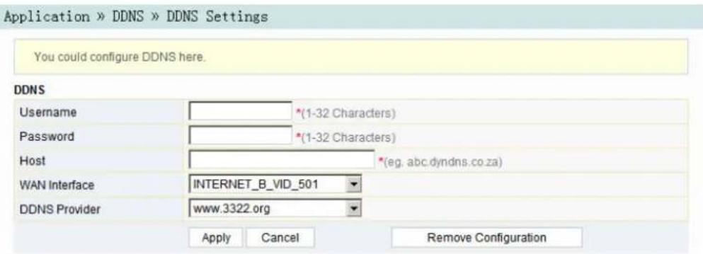
Figure3-34DDNSSettings
- ConfigureparametersrelevanttoDDNSaccordingtotherequirement.
Table3-20describestheparameters.
- ClickApplytosaveandapplytheconfiguration.
Table3-20ParametersforDDNSSettings
| Item | Description |
| Username | TheusernameallocatedbytheDDNSprovider. |
| Password | ThepasswordallocatedbytheDDNSprovider. |
| Host | ThedomainnameallocatedbytheDDNSprovider. |
| WANInterfaceNameofthecreatedWANconnection. | |
| DDNSProvider | TheDDNSserviceprovider.UserscanselectthepresetDDNSproviderorselectOtherecustomizetheproviderandsetthedomainname,serverIPaddress,protocoltypeandURL. |
3.5.2 PortForwarding
TheportforwardingcancreatethemappingbetweentheWANportIPaddress/commonportnumberandtheLANserverIPaddress/privateportnumber.Inthis way,alltheaccessestoacertainserviceportatthisWANportwillbere-directedto thecorrespondingportoftheserverinthedesignatedLAN.
- Select Application in the navigation bar and select Port Forwarding→Port Forwardingintheleftlinkbar.ClickAddtoopentheportforwarding configurationpage,asshowninFigure3-35.

Figure3-35PortForwarding
- Configureparametersrelevanttoportforwardingaccordingtotherequirement. Table3-21 describestheparameters.
- ClickApplytosaveandapplytheconfiguration.
Table3-21ParametersforPortForwarding
| ItemDescription | |
| WAN | ThecorrespondingWANconnectionboundwiththeportforwardingrule. |
| Description | Theportforwardingrulename. |
| PublicPort | TherangeofportsforExtranetdatapackets.lfonlyoneportexists, enterthesameportnumber. |
| IP | ThelPaddressoftheLANvirtualserverforportforwarding. |
| PrivatePort | TherangeoftheLANportforportforwarding.Ifonlyoneportexists, enterthesameportnumber. |
| Protocol | Theprotocolusedfortheporttoforwarddatapackets,includingALL, TCPandUDP. |
| EnableEnablesordisablestherule. | |
3.5.3NAT
NATallowstheconversionbetweenintranetIPaddressesandpublicnetworkIP addresses.NATconvertsagreatnumberofintranetIPaddressesintooneora smallnumberofpublicnetworkIPaddresses,soastosavetheresourceofpublic networkIPaddresses.
TheNATconfigurationbelowcantakeeffectonlywhentheNATfunction is enabled in Network→BroadBand Settings→Internet Settings.
- Select Application in the navigation bar and select NAT→NAT in the left link bar.ClickAddtoopentheNATrulelistconfigurationpage,asshownin Figure3-36.
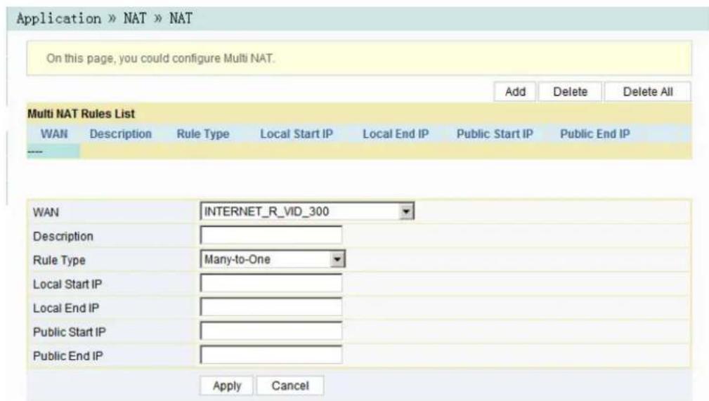
Figure3-36NAT
- Configurerelevantparametersaccordingtotherequirement.Table3-22 describestheparameters.
- ClickApplytosaveandapplytheconfiguration.
Table3-22ParametersforNATConfiguration
| Item | Description |
| WAN | ThecorrespondingWANconnectionboundwiththeNATrule. |
| Description | NATrulename. |
| RuleType | SelecttheNATconversionmode.ItisadvisabletoselectOne-to-Oneor Many-to-One. |
| LocalStartIP | ThestartingIPaddressofintranet. |
| LocalEndIP | TheendingIPaddressofintranet. |
| PublicStartIP | ThestartingIPaddressofthepublicnetwork. |
| PublicEndIP | TheendingIPaddressofthepublicnetwork. |
3.5.4UPnP
TheUPnPsupportstheplugandplayfunctionandtheautomaticdiscoveryfunction ofmultiplenetworkdevices.WhenUPnPisenabled,thedevicesthatsupports UPnPcanbeaddedintothenetworkdynamically.Inthisway,anexternalcomputer canaccesstheresourceontheinternalcomputerwhennecessary.Forexample,whensomeapplicationsoftwarearerunningonaPC,theportmappingtablewillbe generatedontheONTautomaticallyusingtheUPnPprotocol,sothattheoperation canbespedup.
- Select Application in the navigation bar and select UPNP→UPNP in the left linkbartoopentheUPnPconfigurationpage,asshowninFigure3-37.

Figure3-37UPnP
- SelecttoEnableorDisabletheUPnPfunctionasrequired.
- ClickApplytosaveandapplytheconfiguration.
3.5.5DMZ
WhentheONTisworkingintheroutingmode, usersshouldenabletheDMZ functionifahostattheWANsideneedstoaccessacertainhostattheLANside. TheONTwillforwardalltheIPpacketsfromtheWANtothedesignatedDMZhost.
- Select Application in the navigation bar and select DMZ→DMZ in the left link bartoopentheDMZconfigurationpage,asshowninFigure3-38.
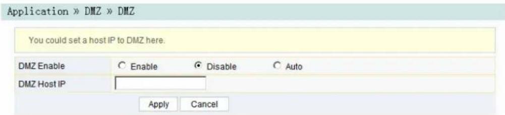
Figure3-38DMZ
- Configurerelevantparametersaccordingtotherequirement.Table3-23 describestheparameters.
- ClickApplytosaveandapplytheconfiguration.
Table3-23ParametersforDMZConfiguration
| Item | Description |
| DMZEnable | EnablesordisablestheDMZfunction.TheoptionsincludeEnable, DisableandAuto.IfEnableisselected,theDMZhostIPaddresssshould beset.IfAutoisselected,theDMZhostusesthefirstIPaddress allocatedbyDHCP. |
| DMZHostIPThehostIP | PaddresssoftheDMZ. |
3.5.6 NetworkDiagnosis
TheONTprovidestwonetworkdiagnosistools.
◆ Pingtest: Testwhethertherouterisnormallyconnectedwiththetargethostor anotherdevice.
◆ Traceroutetest: Checktheroutingconditionfromtheroutertothetargethost.
- Select Application in the navigation bar and select Diagnosis→Diagnosis in the left link bartoopenthenetworkdiagnosis page, asshownin.

Figure3-39NetworkDiagnosis
2.EnterthedestinationIPaddressstobetestedintheDestinationAddressbox, and click Ping or Traceroute to test. The test result will be displayed in the lowertextbox.
3.6 Management
The following introduces how to perform account management, device management and log management in the WebGUI.
3.6.1 AccountManagement
Accountmanagementincludesuseraccountmanagementandmaintenance accountmanagement.
3.6.1.1 UserAccountManagement
Userscanaddordeleteacommonuseraccountormodifythepasswordofa commonuseraccount.
- Select Management in the navigation bar. Select Account Management→UserAccountfromtheleftlinkbartoopentheuseraccountmanagement page,asshowninFigure3-40.

Figure3-40UserAccountManagement
- Addordeleteacommonuseraccountormodifythepasswordofacommon useraccountsrequired.
- ClickApplytosaveandapplytheconfiguration.
3.6.1.2 MaintenanceAccountManagement
Userscanmodifytheusernameandpasswordofthecurrentaccount.
- Select Management in the navigation bar. Select Account Management→MaintenanceAccountfromtheleftlinkbartoopenthemaintenanceaccount managementpage,asshowninFigure3-41.

Figure3-41 MaintenanceAccountManagement
- Modify the username and password of the current accounts required.
- ClickApplytosaveandapplytheconfiguration.
3.6.2 Device Management
The ONT provides multiple device management functions such as restorings some of the configuration data, local upgrade, configuration backup, FTP server, device reboot, and NTP time calibration.
3.6.2.1 RestoringtheConfigurationData
RestorefactorysettingsoftheONT,includingusernameandpasswordforWeb login,SSIDandpasswordforwirelessnetwork,etc.
- Select Management in the navigation bar. Select Device Management→Restorefromtheleftlinkbartoopentheconfigurationrestoringpage,as showninFigure3-42.

Figure3-42RestoringtheConfigurationData
- Click Restore and then click OK in the alert box that appears. Wait until the configurationdataarecompletelyrestored.
3.6.2.2 Local Upgrade
SelectthelocalfileandupgradetheONTsoftware.Duringupgrade,donotpoweroffthedeviceorperformotheroperationstoppreventdamagetothedevice.
- Select Management in the navigation bar. Select Device Management→LocalUpgradefromtheleftlinkbartoopenthelocalupgradepage,asshown inFigure3-43.

Figure3-43LocalUpgrade
- ClickBrowse.Inthedialogboxthatappears,selectthedevicesoftware versiontobeupgradedandclickOpentougradetheONTsoftwareversion.
- Whentheupgradesucceeds, thepagewillpromptfordevicerebooting. Click "Reboot". Afterrebooting, thedevicewillbeupgradedtothenewversion.

Note:
Aftertheupgrade, userscanviewtheSoftwareVersioninthedevice informationpagetocheckwhetherthecurrentversioniscorrect.
3.6.2.3ConfigurationBackup
BackupandsavetheONTconfigurationfilesforrestoringtheconfigurationdata lateron.Beforebackup,enabletheFTPtoolinthecomputer.
- Select Management in the navigation bar. Select Device Management→ConfigBackupfromtheleftlinkbartoopentheconfigurationbackuppage,as showninFigure3-44.

Figure3-44ConfigurationBackup
- Configureparametersrelevanttofilebackup.Table3-24describesthe parameters.
- ClickApplytosavetheconfigurationbackupfile.
Table3-24ParametersforConfigurationBackup
| Item | Description |
| UsernameTheFTPusername. | |
| Password | TheFTPpassword. |
| LocalhostIPLocalIPaddress. | |
| FileName | TheexistingfilenameintheONT. |
3.6.2.4 FTP Server
With the FTP server function of the ON tenabled, users can access the ONT resources via the FTP client end on the PC.
- Select Management in the navigation bar. Select Device Management→FTP ServerfromtheleftlinkbartoopentheFTPserverconfigurationpage, as showninFigure3-45.

Figure3-45 FTPServer
- EnableordisabletheFTPserverfunctionaccordingtotherequirement.Select Enable and then enter the Username and Password for connection with the FTPserver.
- ClickApplytosaveandapplytheconfiguration.
3.6.2.5DeviceReboot
- Select Management in the navigation bar. Select Device Management→DeviceRebootfromtheleftlinkbartoopenthedevicerebootpage,asshown inFigure3-46.

Figure3-46DeviceReboot
- Click Reboot and click OK in the alert box that appears and wait for the device toreboot.

Caution:
Savetheconfiguringdatabeforererebootingthedevicetopreventlossof theconfigurationdata.
Afterthedeviceisrebooted,youneedtowaitforabouttwominutestore-logintotheWebGUIofthedevice.
3.6.2.6 NTPTimeCalibration
UserscanobtaintheprecisetimebyconnectingtheONTtoaNTPserver.
- Select Management in the navigation bar. Select Device Management→NTP CheckTimefromtheleftlinkbartoopentheNTPchecktimepage,asshown inFigure3-47.
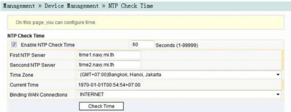
Figure3-47NTPTimeCalibration
- ConfigureparametersrelevanttotheNTPtimecalibration.Table3-25 describestheparameters.
- ClickCheckTimetosaveandapplytheconfiguration.
Table3-25ParametersforNTPTimeCalibration
| Item | Description |
| EnableNTP CheckTime | SelectwhethertoenabletheNTPtimecalibrationfunction. |
| Seconds | Setsthetimeintervalforsynchronizationwiththetimeserver. |
| FirstNTPServerEnterthelPaddressoftheactiveNTPserver. | |
| SecondNTP Server | EnterthelPaddressofthestandbyNTPserver. |
| TimeZone | Selectthetimezoneaccordingtothelocationofthedevice. |
| CurrentTime | WhenNTPCheckTimeisenabled,timewillbecalibratedaccordingtothe equipmentlocation,andthelocaltimewillbedisplayed.WhenNTPCheckTimeisdisabled,thesysteminitialtime(1970-01-01)or thepreviouscalibratedtimewillbedisplayed. |
| BindingWAN Connections | SelecttheWANconnectiontypefortimecalibration. |
3.6.3 LogManagement
The LogfilesrecordkeyoperationsandactionsontheONT.Userscanviewthe informationsavedinlogasneeded.
Select Management in the navigation bar. Select Log→Log from the left link bar to opentheloginformationpage,asshowninFigure3-48.
![Management » Log » Log You can view log on this page. Log Information Manufacturer:FiberHome; ProductClass:HG6244C SerialNumber:FHTT91FBCE70 ONU IP:192.168.1.1; HWVer:WKE2.094.289A01; SWVer:RP2600(00.00); 1970-1-1 00:02:08 [Informational] Restore finished! 1970-1-1 00:01:30 [Informational] webLogin finished! 1970-1-1 00:01:44 [Informational] webLogin finished! 1970-1-1 00:01:51 [Informational] webLogout finished! 1970-1-1 00:00:43 [Informational] webLogin finished! 1970-1-1 00:00:49 [Informational] webLogin finished! 1970-1-2 16:21:45 [Informational] webLogin finished! 1970-1-2 16:22:24 [Informational] webLogout finished! 1970-1-2 16:22:29 [Informational] webLogin finished! 1970-1-2 16:24:56 [Informational] Update success! 1970-1-2 16:25:24 [Informational] going to reboot! 1970-1-1 00:18:35 [Informational] webLogin finished! 1970-1-1 00:21:36 [Informational] set wan cfg finished!](/content/2026/06/1359203/images/9432a087b0a6d601de7946d96ed9ab5fcd54860e3b3908759b5e0002c7e9037d.jpg)
Figure3-48Log
4HandlingCommonProblems
The following introduces how to handle common problems encountered equipment operation and servicetest.
PowerStatusIndicatorLEExtinguished
RegisterStatusIndicatorLEDExtinguished
OpticalSignalStatusIndicatorLEDBlinking
EthernetInterfaceStatusIndicatorLEDExtinguished
FailingtoAccessLocalWebLoginGUIandFailingtoPing192.168.1.1
FailingtoAccessInternetUsingtheLANPort
√ MeasuredInternetAccessRateLowerorHigherThanTheStandardValue
ConnectiontoIPTVFailed
IPTVPictureSuspended
TestofVoiceServiceFailed
4.1 PowerStatusIndicatorLEDExtinguished
Handle the problem according to the procedures below:
- Checkwhetherthemainssupplyisnormal.
- Check whether the power adapter match the device.
- Checkwhetherthepowerbuttonispresseddown.
- Checkwhetherthepowercableconnectionisnormal.
4.2RegisterStatusIndicatorLEDExtinguished
Handle the problem according to the procedures below:
- Checkwhetherthedevicepowersupplyisnormal.
- Checkwhethertheopticalfiberconnectionisnormal.
- Check whether the ON has obtained the ISP authorization.
- Checkwhethertheopticalinterfaceisnormal;ifnot,replacethedevice.
4.3OpticalSignalStatusIndicatorLEDBlinking
Handle the problem according to the procedures below:
- Checkwhethertheopticalfiberisdamaged.
- Checkwhethertheopticalfiberisconnectedtothecorrectinterface.
- CheckwhethertheRxopticalpoweroftheONT(measuredwiththeoptical powermeter)isbelowspecifications.
- Check whether the ONToptical module is aged or damaged.
- Check whether the local device is faulty.
4.4 Ethernet Interface Status Indicator LED Extinguished
Handle the problem according to the procedures below:
- Checkwhetherthenetworkcableisdamagedorconnectedincorrectly.
- Checkwhetherthecolor-codingschemeofthenetworkcableisincorrect;ifso, replaceitwithastandardCAT-5twistedpairnetworkcable.
- Check whether thenetwork cable length exceeds the allowed range (100m).
4.5 FailingtoAccessLocalWebLoginGUland FailingtoPing192.168.1.1
Handle the problem according to the procedures below:
- CheckwhethertheLANportindicatorLEDisON;ifnot,replacethenetwork cable.
- CheckwhetherthecomputerissetwithafixedIPaddressinthenetwork segmentof192.168.1.x.
4.6 FailingtoAccessInternetUsingtheLANPort
Handle the problem according to the procedures below:
- Check whether the computer is set with a fixed IP address. If yes, modify the configurations that the computer can obtain an IP address automatically. Then retry the connection.
- If the computer is obtaining IP addresses automatically, check whether the computer has obtained an IP address in thenetwork segment of 192.168.x.x.
- Contact the personnel in the network management center to check whether the WAN is connected correctly and bound with the LAN port.
4.7 Measured Internet Access Rate Lower or Higher Than The Standard Value
Contact the personnel in the network management center to check whether the bandwidth profile is configured correctly and bound to the ONT.
4.8ConnectiontolPTVFailed
Handle the problem according to the procedures below:
- Check whether the STB is connected to the ONT port correctly and configured with IPTV account number and password correctly.
- ContactthenetworkmanagementcentertocheckwhethertheIPTVservice workorderhasbeendelivered.
- CheckwhethertheONTconnectionportistheserviceportboundwiththeIPTVworkorder.
4.9IPTVPictureSuspended
Handle the problem according to the procedures below:
- Check whether the quality of thenetwork cable connecting the STB (SetTopBox) issatisfactory.
- ContactthenetworkmanagementcentertocheckwhethertheIPTVserviceis boundwiththeratelimitingprofilecorrectly.
- Replacethe STB.
4.10 TestofVoiceServiceFailed
Handle the problem according to the procedures below:
- Checkwhetheryoucanhearthecurrenttonewhenyougooff-hook;ifno, checkwhetherthephonecableisconnectedcorrectly.
- Checkwhetheryoucanhearthedialtonewhenyougooff-hook;ifno,contact thenetworkmanagementcentertocheckwhetherthevoiceserviceworkorder hasbeendeliveredcorrectlyandwhethertheuplinkdevicehasdeliveredthe configurationdatatothevoiceserviceportoftheONT.
- LogintotheONTtocheckwhetherithasobtainedanIPaddressforvoice service.
- Contact the soft switch platform to check whether the voice encoded data have been configured.
5StandardsandProtocols
| ClassificationStandardNumberTitle | ||
| GPON | ITU-TG.984.1 | Gigabit-capablepassiveopticalnetworks(GPON):General characteristics |
| ITU-TG.984.2 | Gigabit-capablePassiveOpticalNetworks(GPON):PhysicalMedia Dependent(PMD)layerspecification | |
| ITU-TG.984.3 | Gigabit-capablePassiveOpticalNetworks(G-PON):Transmission convergencelayerspecification | |
| ITU-TG.984.4 | Gigabit-capablepassiveopticalnetworks(G-PON):ONT managementandcontrolinterfacespecification | |
| Ethernet | IEEE802-2001 | IEEEStandardforLocalandMetropolitanAreaNetworks:Overview andArchitecture |
| IEEE802.1D-2004 | IEEEStandardforLocalandmetropolitanareanetworks:Media AccessControl(MAC)Bridges | |
| IEEE802.1Q-2005 | IEEEStandardforLocalandMetropolitanAreaNetworks-Virtual BridgedLocalAreaNetworks-Amendment4:ProviderBridges | |
| IEEE802.1ad | IEEEStandardforLocalandMetropolitanAreaNetworks-Virtual BridgedLocalAreaNetworks-Amendment4:ProviderBridges | |
| IEEE802.1x-2004 | IEEEStandardforLocalandMetropolitanAreaNetworksPort-Based NetworkAccessControl | |
| IEEE802.1ag-2007 | IEEEStandardforLocalandMetropolitanAreaNetworksVirtual BridgedLocalAreaNetworksAmendment5:ConnectivityFault Management | |
| IEEE802.3-2005 | IEEEStandardforInformationtechnology-Telecommunicationsand informationexchangebetweensystems-Localandmetropolitanarea networks-SpecificrequirementsPart3:CarrierSenseMultiple AccesswithCollisionDetection(CSMA/CD)AccessMethodand PhysicalLayerSpecifications | |
| IEEE802.3z | GigabitEthernetStandard | |
| IEEE802.1p | Trafficclassexpeditinganddynamicmulticastfiltering.Describes importantmethodsforprovidingQoSatMAClevel | |
| TR-101 | MigrationtoEthernet-BasedBroadbandAggregation | |
| TR-143 | EnablingNetworkThroughputPerformanceTestsandStatistical Monitoring | |
| VoIP | ITU-TG.711 | Pulsecodemodulation(PCM)ofvoicefrequencies |
| ITU-TG.711.1 | WidebandembeddedextensionforG.711pulsecodemodulation | |
| ITU-TG.722 | 7kHzaudio-codingwithin64kbit/s | |
| ITU-TG.723.1 | Dualratespeechcoderformultimediacommunicationstransmittingat 5.3and6.3kbit/s | |
| ITU-TG.729 | Codingofspeechchat8kbit/susingconjugate-structurealgebraic-code-excitedlinearprediction(CS-ACELP) | |
| ITU-TG.729.1 | G.729basedEmbeddedVariablebit-ratecoder:An8-32kbit/sscalablewidebandcoderbitstreaminteroperablewithG.729 | |
| ITU-TG.165EchoCancellers | ||
| ITU-TG.168 | Digitalnetworkechocancellers | |
| Multicast | IETFRFC2236 | InternetGroupManagementProtocol,Version2 |
| IETFRFC3376 | InternetGroupManagementProtocol,Version3 | |
| IETFRFC4541 | ConsiderationsforInternetGroupManagementProtocol(IGMP)and MulticastListenerDiscovery(MLD)SnoopingSwitches | |
| Time | IETFRFC1305 | NetworkTimeProtocol(Version3)Specification,Implementation and Analysis |
| IETFRFC2030 | SimpleNetworkTimeProtocol(SNTP)Version4forIPv4,IPv6and OSI | |
| EMC | EN300386 | ElectromagneticcompatibilityandRadiospectrumMatters(ERM);Telecommunicationnetworkequipment;Electromagnetic Compatibility(EMC)requirements |
| CISPR22(EN55022) | Informationtechnologyequipment-Radiodisturbancecharacteristics -Limitsandmethodsofmeasurement | |
| CISPR24(EN55024) | Informationtechnologyequipment-Immunitycharacteristics-Limits andmethodsofmeasurement | |
| OtherTR-069 | CPEWANManagementProtocol | |
AppendixAAbbreviations
| ONT | OpticalNetworkTerminal |
| FTTH | FiberToTheHome |
| GPON | Gigabit-capablePassiveOptical Network |
| ODN | OpticalDistributionNetwork |
| OLT | OpticalLineTermination |
| DBA | DynamicBandwidthAllocation |
| XML | ExtensibleMarkupLanguage |
| GEM | GPONEncapsulationMode |
| ATM | AsynchronousTransferMode |
| OAM | Operation,AdministrationAnd Maintenance |
FECForwardErrorCorrection
| TDMA | TimeDivisionMultipleAccess |
| PLOAM | PhysicalLayerOperations,AdministrationandMaintenance |
| OMCI | ONUManagementandControlInterface |
T-CONTTransmissionContainer
| NSR | NetworkSecurityRecorder |
| AES | AdvancedEncryptionStandard |
MACMediumAccessControl
| IGMP | InternetGroupManagementProtocol |
| VLAN | VirtualLocalAreaNetwork |
| QoS | QualityofService |
ACLAccessControlList
| WRR | WeightedRoundRobin |
| DHCP | DynamicHostConfigurationProtocol |
| PPPoE | PointtoPointProtocoloverEthernet |
| NATNetworkAddressTranslation | |
| DMZ | DemilitarizedZone |
| ARP | AddressResolutionProtocol |
| UPnP | UniversalPlugandPlay |
| DoSDenialofService | |
| DDoSDistributedDenialofService | |
| URL | UniformResourceLocator |
| HTTPS | HyperTextTransferProtocoloverSecureSocketLayer |
| CATVCableAntennaTelevision | |
| CoSClassofService | |
| SIPSessionInitiationProtocol | |
| VoIPVoiceoverInternetProtocol | |
| RTP | Real-timeTransportProtocol |
| IGD_WLAN_SSID | ServiceSetIdentifier |
| WAN | WideAreaNetwork |
| LAN | LocalAreaNetwork |
| WLAN | WirelessLocalAreaNetworks |
| MTUMaximumTransmissionUnit | |
| PPPoE | PointtoPointProtocoloverEthernet |
| DTMF | DualToneMultiFrequency |
| VPN | VirtualPrivateNetwork |
| DDNS | DynamicDomainNameServer |
| FTPFileTransferProtocol | |
| ADSL | AsymmetricDigitalSubscriberLine |
| BRAS | BroadbandRemoteAccessServer |
| BSCBaseStationController | |
| CDRCallDetailRecord | |
| CPE | CustomerPremiseEquipment |
| DSL | DigitalSubscriberLine |
| DSLAM | DigitalSubscriberLineAccessMultiplexer |
| EFM | EthernetintheFirstMile |
| EMC | ElectroMagneticCompatibility |
| EPON | EthernetPassiveOpticalNetwork |
| EPRS | EthernetRingProtectionSwitching |
FDB ForwardingDatabase
FolPFaxoverIP
FTTA FiberToTheAntenna
FTTB FiberToTheBuilding
FTTCFiberToTheCurb
FTTDp FiberToTheDistributionPoint
FTTM FiberToTheMobile
FTTOFiberToTheOffice
GUI GraphicalUserInterface
HG HomeGateway
IntegratedServicesDigital
Network
ICMP InternetControlMessageProtocol
IMS IPMultimediaSubsystem
IP InternetProtocol
LACP LinkAggregationControlProtocol
LAN LocalAreaNetwork
MDU Multi-DwellingUnit
MGC MediaGatewayController
MGCP MediaGatewayControlProtocol
MLD MulticastListenerDiscover
MoIPModemoverIP
MTBF MeanTimeBetweenFailure
MSANMulti-ServiceAccessNetwork
MSTP MultipleSpanningTreeProtocol
NGNNextGenerationNetwork
OLT OpticalLineTermination
OSPF OpenShortestPathFirst
OpticalTimeDomain
Reflectometer
PON PassiveOpticalNetwork
POTS PlainOldTelephoneService
ppm partspermillion
PRI PrimaryRateInterface
PSTN PublicSwitchedTelephone
Network
QinQ 802.1Q-in-802.1Q
| RIP | RoutingInformationProtocol |
| RNCRadioNetworkController | |
| RSTP | RapidSpanningTreeProtocol |
| RSSI | ReceivedSignalStrengthIndication |
| SBAStaticBandwidthAllocation | |
| SBU | SingleBusinessUnit |
| SCB | SingleCopyBroadcast |
| SDH | SynchronousDigitalHierarchy |
| SFU | SingleFamilyUnit |
| SHDSL | Single-pairHighbitrateDigitalSubscriberLine |
| SNIServiceNodeInterface | |
| SNMP | SimpleNetworkManagementProtocol |
| SP | StrictPriority |
| STB | SetTopBox |
| STM | SynchronousTransportModule |
| STP | Straight-ThroughProcessing |
| SSHSecureShell | |
| TCPTransmissionControlProtocol | |
| TDM | TimeDivisionMultiplex |
| TG | TrunkGateway |
| TOD | TimeofDay |
| ToS | TypeofService |
| UDP | UserDatagramProtocol |
| UNI | User-NetworkInterface |
| VDN | VideoDistributionNetwork |
| VDSL | VeryHighSpeedDigitalSubscriberLine |
| WDM | WavelengthDivisionMultiplexing |
ProductDocumentationCustomerSatisfactionSurvey
ThankyouforreadingandusingtheproductdocumentationprovidedbyFiberHome.Pleaseatakeamomentto completethissurvey.Youranswerswillhelpustoimprovethedocumentationandbettersuityourneeds.Your responseswillbeconfidentialandgivenseriousconsideration.Thepersonalinformationrequestedisusedfor nootherpurposesthantorespondtoyourfeedback.
| Name | |
| PhoneNumber | |
| EmailAddress | |
| Company |
Tohelpusbetterunderstandyourneeds,pleasefocusyouranswersonasingledocumentationoracomplete documentationset.
| DocumentationName | |
| CodeandVersion |
Usageoftheproductdocumentation:
- How oftendoyouusethedocumentation?
□ Frequently □ Rarely □ Never □ Other (please specify) ____
- Whendoyouusethedocumentation?
□ in starting up a project □ in installing the product □ in daily maintenance □ in trouble shooting □ Other(pleasespecify) ____
- What is the percentage of the operations on the product for which you can get instruction from the documentation?
□ 100% □ 80% □ 50% □ 0% □ Other (please specify) ____
- Are you satisfied with the promptness with which we updated the documentation?
□Satisfied □Unsatisfied(youradvice)
- Which documentation form do you prefer?
□ Print edition □ Electronic edition □ Other (please specify) ____
Qualityoftheproductdocumentation:
- Istheinformationorganizedandpresentedclearly?
□Very □Somewhat □Notatall(youradvice)
2.Howdoyoulikethelanguagestyleofthedocumentation?
□Good □Normal □Poor(pleasespecify)
-
Areanycontentsinthedocumentationinconsistentwiththeproduct?
-
Istheinformationcompleteinthedocumentation?
□Yes
□No(Pleasespecify)
- Are the product working principles and the relevant technologies covered in the documentation sufficient for youtogetknownandusetheproduct?
□Yes
□No(Pleasespecify)
- Can you successfully implement a task following the operation steps given in the documentation?
□Yes(Pleasegiveanexample)
□No(Pleasespecifythereason)
- Which part of the documentation are you satisfied with?
8.Whichpartsofthedocumentationareyouunsatisfiedwith?Why?
9. WhatisyouropinionontheFiguresinthedocumentation?
□Beautiful □Unbeautiful(youradvice)
□Practical □Unpractical(youradvice)
- Whatisyouropiniononthelayoutofthedocumentation?
□Beautiful □Unbeautiful(youradvice)
- Thinking of the documentations you have ever read offered by other companies, how would you compare our documentation to them?
Productdocumentationsfromothercompanies:
Satisfied(pleasespecify)
Unsatisfied(pleasespecify)
- Additional comments about our documentation or suggestions on how we can improve:
Thankyouforyourassistance.Pleasefaxorsendthecompletedsurveytousatthecontactinformation includedinthedocumentation.Ifyouhaveanyquestionsorconcernsaboutthissurveypleaseemailatedit@fiberhome.com

- Thankyouforchoosingourproducts.
- FiberhomeTelecommunicationTechnologiesCo.,Ltd.
- LegalNotice
- Allrightsreserved
- SafetyPrecautions
- Contents
- Safety Precautions....I
- Web Configuration Guide....17
- Network....29
- Security....49
- Application....62
- Management 67
- Handling Common Problems 75
- Standards and Protocols....79
- 1DocumentationGuide
- DocumentOrientation
- IntendedReaders
- VersionInformation
- Content
- 2ProductIntroduction
- ProductPositioning
- 2.2ProductSpecifications
- 2.3InterfaceSpecifications
- GPONInterface
- LANInterface
- 2.3.3POTSInterface
- 2.3.4Wi-FilInterface
- 2.3.5USBInterface
- Introduction to the HG6244C
- Appearance
- Appearance
- InterfaceandButton
- IndicatorLEDDescription
- ProductCharacteristics
- GPONaccesscapability
- Abundantservicetypes
- 3.Wi-FiWirelessAccess
- Networkstorage and filesharing
- Gatewayfunctions
- Remote automatic provisioning of services, maintenance and management
- Functions and Features
- Technical Specifications
- 3WebConfigurationGuide
- Logging into Web Configuration GUI Locally
- Prerequisites
- PlanningData
- OperationProcedure
- Note:
- 3.2Status
- DeviceInformation
- Wireless Network Status
- Wireless Network Status
- 3.2.2.2Wi-FiUserList
- 3.2.3WANSideStatus
- LANSideStatus
- LANSideStatus
- 3.2.4.2DHCPUserList
- Optical Power Status
- 3.2.6VoiceStatus
- 3.3Network
- 3.3.1WLANSettings
- BasicParameters
- AdvancedConfiguration
- 3.3.1.3Wi-FiControl
- 3.3.1.4WPSSConfiguration
- LAN Settings
- Broadband Settings
- 3.3.4DHCPServer
- AuthenticationSetting
- 3.3.6VoiceConfiguration
- 3.3.6.1KeyParameters
- Basic Parameters
- DigitmapandLength
- 3.3.6.5Coding
- Security
- Firewall
- 3.4.1.2IPFiltering
- ClickApplytosaveandapplytheconfiguration.
- 3.4.1.4URLFiltering
- 3.4.1.5DHCPFiltering
- Anti-portScan
- MACAddressFiltering
- RemoteControl
- DynamicDoS
- HTTPS
- Caution:
- 3.5Application
- 3.5.1DDNS
- PortForwarding
- 3.5.3NAT
- 3.5.4UPnP
- 3.5.5DMZ
- NetworkDiagnosis
- Management
- AccountManagement
- UserAccountManagement
- MaintenanceAccountManagement
- Device Management
- RestoringtheConfigurationData
- Local Upgrade
- 3.6.2.3ConfigurationBackup
- FTP Server
- 3.6.2.5DeviceReboot
- NTPTimeCalibration
- LogManagement
- 4HandlingCommonProblems
- PowerStatusIndicatorLEDExtinguished
- 4.2RegisterStatusIndicatorLEDExtinguished
- 4.3OpticalSignalStatusIndicatorLEDBlinking
- Ethernet Interface Status Indicator LED Extinguished
- FailingtoAccessLocalWebLoginGUland FailingtoPing192.168.1.1
- FailingtoAccessInternetUsingtheLANPort
- Measured Internet Access Rate Lower or Higher Than The Standard Value
- 4.8ConnectiontolPTVFailed
- 4.9IPTVPictureSuspended
- TestofVoiceServiceFailed
- 5StandardsandProtocols
- AppendixAAbbreviations
- ProductDocumentationCustomerSatisfactionSurvey
- Usageoftheproductdocumentation:
- Qualityoftheproductdocumentation:
Brand : FiberHome
Model : HG6244C
Category : Router