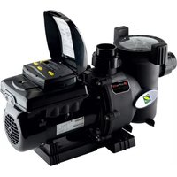
FloPro VS - Pump ZODIAC - Free user manual and instructions
Find the device manual for free FloPro VS ZODIAC in PDF.


| Product Type | Variable Speed Pool Pump |
| Brand | Zodiac |
| Model | FloPro VS |
| Dimensions (H x W x D) | 30 cm x 25 cm x 20 cm |
| Weight | 10 kg |
| Power Supply | 230 V / 50 Hz |
| Motor Power | 1.5 HP |
| Maximum Flow Rate | 300 L/min |
| Maximum Head | 15 m |
| Inlet / Outlet Size | 50 mm / 50 mm |
| Speed Settings | Variable speed (multiple presets) |
| Energy Efficiency | Up to 80% energy savings vs single-speed |
| Noise Level | Low noise operation (< 50 dB) |
| Ingress Protection | IP55 |
| Filter Basket | Large transparent basket, easy to clean |
| Pump Housing | Reinforced thermoplastic |
| Impeller | Noryl / engineered plastic |
| Seal | Mechanical seal (ceramic/carbon) |
| Wiring Requirements | Direct connection, recommended 2.5 mm² cable |
| Operating Temperature | 5°C to 40°C |
| Maintenance | Clean filter basket weekly; check seals annually |
| Safety Features | Thermal overload protection, IP55 rated |
| Spare Parts Availability | Available through Zodiac dealers (mechanical seal, impeller, housing) |
| Warranty | 2 years (subject to terms) |
Frequently Asked Questions - FloPro VS ZODIAC
User questions about FloPro VS ZODIAC
0 question about this device. Answer the ones you know or ask your own.
Ask a new question about this device
Download the instructions for your Pump in PDF format for free! Find your manual FloPro VS - ZODIAC and take your electronic device back in hand. On this page are published all the documents necessary for the use of your device. FloPro VS by ZODIAC.
USER MANUAL FloPro VS ZODIAC
natural_image
Technical line drawing of a pump assembly (no text or symbols on the diagram itself)
WARNING
FOR YOUR SAFETY: This product must be installed and serviced by a professional service technician, qualified in pool/spa installation. The procedures in this manual must be followed exactly. Improper installation and/or operation can create dangerous electrical hazards, which can cause high voltages to run through the electrical system, possibly causing death, serious injury or property damage. Improper installation and/or operation will void the warranty.

ATTENTION INSTALLER: This manual contains important information about the installation, operation and safe use of this product. This information should be given to the owner/operator of this equipment.
Important Safety Instructions
READ AND FOLLOW ALL INSTRUCTIONS
All electrical work must be performed by a licensed electrician and conform to all national, state, and local codes. When installing and using this electrical equipment, basic safety precautions should always be followed, including the following:
WARNING
RISK OF SUCTION ENTRAPMENT HAZARD, WHICH, IF NOT AVOIDED, CAN RESULT IN SERIOUS INJURY OR DEATH. Do not block pump suction, as this can cause severe injury or death. Do not use this pump for wading pools, shallow pools, or spas containing bottom drains, unless the pump is connected to at least two (2) functioning suction outlets. Drain covers must be certified to the latest published edition of ANSI/ASME A112.19.8 or it's successor standard ANSI/APSP-16. In Australia AS1926.3 is also an acceptable standard.
WARNING
To reduce the risk of injury, do not permit children to use this product.
WARNING
A check valve can interfere with the proper operation of certain Suction Vacuum Release System (SVRS) products. To avoid possible entrapment hazard, serious injury, or death, make sure to review the operation/owners manual of your particular SVRS product before installing the check valve.
WARNING
To reduce the risk of property damage or injury, do not attempt to change the backwash (multiport, slide, or full flow) valve position with the pump running.
WARNING
Zodiac® Pumps are powered by a high-voltage electric motor and must be installed by a licensed or certified electrician or a qualified swimming pool service technician.
WARNING
The pump is for fixed installations only and to be used in conjunction with swimming pool equipment. (e.g. filters). The pump is to be installed in accordance with the relevant requirements of the Australian wiring rules AS/NZS 3000. Also refer to the installation instructions relating to the swimming pool equipment for which the pump will be an integral part. The pump is to be supplied through a residual current device (RCD) with a rated residual operating current of 30mA. If the supply cord is damaged it must be replaced by the manufacturer or its service agent or similarly qualified person in order to avoid hazard.
WARNING
Incorrectly installed equipment may fail, causing severe injury or property damage.
WARNING
- Do not connect system to an unregulated city water system or other external source of pressurized water producing pressures greater than 35 PSI.
- Trapped air in the system can cause the filter lid to be blown off, which can result in death, serious personal injury, or property damage. Be sure all air is out of the system before operating.
WARNING
To minimize risk of severe injury or death, the filter and/or pump should not be subjected to the piping system pressurization test.
Local codes may require the pool piping system to be subjected to a pressure test. These requirements are generally not intended to apply to the pool equipment, such as filters or pumps.
Zodiac ^® pool equipment is pressure tested at the factory.
If, however, the WARNING cannot be followed and pressure testing of the piping system must include the filter and/or pump, BE SURE TO COMPLY WITH THE FOLLOWING SAFETY INSTRUCTIONS:
- Check all clamps, bolts, lids, lock rings, and system accessories to ensure they are properly installed and secured before testing.
- RELEASE ALL AIR in the system before testing.
• Water pressure for test must NOT EXCEED 35 PSI.
• Water temperature for test must NOT EXCEED 100°F (38°C). - Limit test to 24 hours. After test, visually check system to be sure it is ready for operation.
Notice: These parameters apply to Zodiac equipment only. For non-Zodiac equipment, consult the equipment manufacturer.
WARNING
Chemical spills and fumes can weaken pool/spa equipment. Corrosion can cause filters and other equipment to fail, resulting in severe injury or property damage. Do not store pool chemicals near your equipment.
CAUTION
Do not start pump dry! Running the pump dry for any length of time will cause severe damage and will void the warranty.
CAUTION
This pump is for use with permanently installed pools and may also be used with hot tubs and spas, if so marked. Do not use with storable pools. A permanently installed pool is constructed in or on the ground or in a building, such that it cannot be readily disassembled for storage. A storable pool is constructed so that it may be readily disassembled for storage and reassembled to its original integrity.
CAUTION
Do not install beneath the skirt of a hot tub. The pump requires adequate ventilation to maintain air temperature at less than the maximum ambient temperature rating listed on the motor rating plate.
SAVE THESE INSTRUCTIONS

WARNING
SUCTION HAZARD. Can cause serious injury or death. Do not use this pump for wading pools, shallow pools, or spas containing bottom drains, unless pump is connected to at least two (2) functioning suction outlets.
WARNING
Pump suction is hazardous and can trap and drown or disembowel bathers. Do not use or operate swimming pools, spas, or hot tubs if a suction outlet cover is missing, broken, or loose. The following guidelines provide information for pump installation that minimizes risk of injury to users of pools, spas, and hot tubs:
Entrapment Protection - The pump suction system must provide protection against the hazards of suction entrapment.
Suction Outlet Covers - All suction outlets must have correctly installed, screw-fastened covers in place. All suction outlet (drain) covers must be properly maintained. They must be replaced if cracked, broken, or missing. Drain covers must be listed/certified to the latest published edition of ANSI®/ASME® A112.19.8 or its successor standard, ANSI/APSP-16. In Australia, AS1926.3 is also an acceptable standard. The pool must be shut down and bathers must be restricted from entering the pool until any cracked, broken, or missing drain covers are replaced.
Number of Suction Outlets Per Pump - Provide at least two (2) hydraulically-balanced suction outlets, with covers, as suction outlets for each circulating pump suction line. The centers of the suction outlets (suction outlets) on any one (1) suction line must be at least three (3) feet apart, center to center. See Figure 1.
The system must be built to include at least two (2) suction outlets (drains) connected to the pump whenever the pump is running. However, if two (2) suction outlets run into a single suction line, the single suction line may be equipped with a valve that will shut off both suction outlets from the pump. The system shall be constructed such that it shall not allow for separate or independent shutoff or isolation of each drain. See Figure 1.
Additional pumps can be connected to a single suction line as long as the requirements above are met.
Water Velocity - The maximum water velocity through the suction outlet assembly and its cover for any suction outlet must not exceed the suction outlet assembly and its cover's maximum design flow rate. The suction outlet (drain) assembly and its cover must comply with the latest version of ANSI®/ASME® A112.19.8, the standard for Suction Fittings For Use in Swimming Pools, Wading Pools, Spas,and Hot Tubs, or its successor standard, ANSI/ASME APSP-16. In Australia, AS1926.3 is also an acceptable standard.
Testing and Certification - Suction outlet covers must have been tested by a nationally recognized testing laboratory and found to comply with the latest published edition of ANSI/ASME A112.19.8 or its successor standard, ANSI/APSP-16, the standard for Suction Fittings For Use in Swimming pools, Wading Pools, Spas, and Hot Tubs. In Australia, AS1926.3 is also an acceptable standard.
Fittings - Fittings restrict flow; for best efficiency use fewest possible fittings (but at least two (2) suction outlets).
Avoid fittings that could cause an air trap.
Pool cleaner suction fittings must conform to applicable International Association of Plumbing and Mechanical Officials (IAPMO) standards.
Contents
- Information before installing....6
1.1 General delivery terms and conditions....6
1.2 Contents....6
1.3 Technical specifications .... 6
- Installation....6
2.1 Selection of the location .... 6
2.2 Installing the appliance .... 7
2.3 Hydraulic connections 7
2.4 Electric connections 8
- Use....10
3.1 User interface presentation.... 10
3.2 Checks before starting up.... 10
3.3 Start up the appliance .... 10
3.4 User interface settings and use....11
- Maintenance....17
4.1 Maintenance instructions.... 17
4.2 Winterizing 17
- Troubleshooting .... 18
- Registering the product....18

Are available in the appendices at the end of these instructions:
- Dimensions
- Description
• Performance graphs
1. Information before installing
1.1 General delivery terms and conditions
All equipment, even postage and packing paid, travels at the risks and perils of the recipient. Written reserves should be made on the transporter's delivery documents if damage during transport is discovered by the recipient (confirmed by registered letter to the transporter within 48 hours).
1.2 Contents
 |  |  |
| FloPro VS Bases Cable gland | ||
| x1 | x2 - Item sold separately (A0130800) | x1 |
1.3 Technical specifications
• Power: 1.65HP - 1.2kW
• Operation at from 600 to 3450 rpm (settings per 10 rpm step)
• Number of programmable speeds: 8
- Flow rate at 8 metres hydraulic head: 400 litres/Minute at 3000 RPM
- Operating temperatures: from 2 to 50^ air, and 2 to 35^ water
• Protection index: IPX4
2. Installation
2.1 Selection of the location
• The pump must be installed:
- before the filter, the heating system, or the water treatment,
- at a minimum distance of 3.5 meters from the edge of the pool in order to avoid any projections of spray onto the appliance. Some standards allow for other distances. Refer to the regulations in effect in the country of installation.
- ideally 30 cm below the water level,
- outside areas liable to flooding, or on a base with drainage,
- in a ventilated zone to allow for cooling.
- The pump must not be installed:
- in an area subjected to water spray, rain, direct sunlight,
- at more than 1 metre above the water level,
- close to a heat source or to a source of inflammable gas.
• Install a check valve if the pump is installed above the water level.
WARNING
A check valve can interfere with the proper operation of certain Suction Vacuum Release System (SVRS) products. To avoid possible entrapment hazard, serious injury, or death, make sure to review the operation/owners manual of your particular SVRS product before installing the check valve.
- It must have easy access for any work to be carried out on the appliance.
- Use as few bends as possible.
- If installed below the level of the pool water, isolation/shutoff valves must be installed on the admission (suction) and discharge piping of the pump.
2.2 Installing the appliance
• Install on a stable, solid (concrete slab for example) and level surface.
- If necessary, use the optional bases not included (small base + spacers and large base, use only one, or both combined) to raise the pump to the level of the existing piping. Bases can be ordered separately (A0130800).
- Screw the pump (and the base(s) if applicable) to the ground using suitable lag-screws.

natural_image
Pure electrical circuit lines without any symbols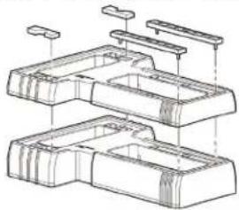
natural_image
Technical line drawing of a multi-layered mechanical or electronic component assembly (no text or symbols)2.3 Hydraulic connecti ons
flowchart
graph TD
    A["Top Section"] --> B["Main Tank"]
    B --> C["Valve 1"]
    B --> D["Valve 2"]
    B --> E["Valve 3"]
    B --> F["Valve 4"]
    B --> G["Bottom Section"]
    G --> H["Reactor Unit ①"]
    G --> I["Reactor Unit ②"]
    G --> J["Reactor Unit ③"]
    G --> K["Reactor Unit ④"]
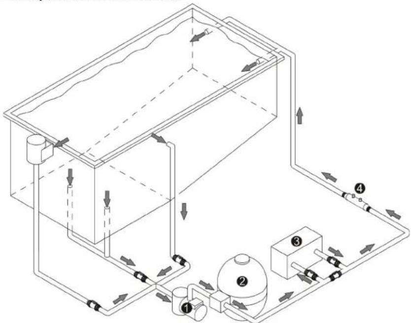
1: pump
2: fi lter
3: heating system
4: water treatment system

Follow the hydraulic connecti on directi on (see § "Sizes" in the appendix).
| Pipe | Maximum admission flow rate1.8 metres/second | Maximum discharge flow rate at2.4 metres/second |
| 40 mm 8.5 m3/h | 11.3 m3/h | |
| 50 mm 14 m3/h | 19 m3/h |
- Choose the piping size depending on the pool size and in compliance with locally applicable hydraulic rules.
- The performance graphs are available in the appendix for use in pipe sizing.
- The use of union fittings on the admission and discharge is recommended to make work on the appliance easier (the pump admission and discharge have a 2" interior threading).
- If more than 10 bends are to be installed on the hydraulic circuit, increase the pipe diameter.
- Avoid high points to facilitate priming.
• Make sure the hydraulic fittings are correctly tightened and that there are no leaks. - The pipes must be supported to avoid any risk of breakage due to the weight of the water.
2.4 Electric connecti ons
- The pump will only start when commanded by its user interface or an external controller (AquaLink® TRi for example).
WARNING
ELECTRICAL SHOCK HAZARD
- Only a qualified and experienced technician is authorized to wire inside the appliance.
- Loose terminals can cause the terminal block to heat and lead to the warranty being voided.
- If the power supply cable is damaged it should be replaced by a qualified technician.
a) Default Dip Switch Positions
- The user interface is fixed and wired to the pump in the factory.
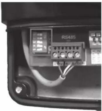
- The pump communicates with its user interface using an RS485 cable.
| Switch positi on 1 2 3 4 5 | |||||
| For control using the user interface on on off off on | |||||
natural_image
Close-up of an electronic device panel with visible wiring and a labeled component (RS485), no readable text or symbols beyond the label.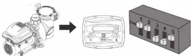
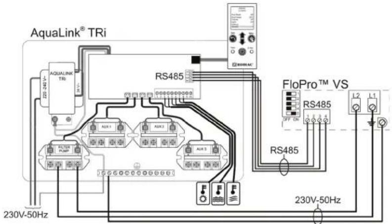
c) AquaLink TRi connecti on opti on
WARNING
ELECTRICAL SHOCK HAZARD
Turn off all switches and the main breaker in the Pump electrical circuit before starting the procedure. Failure to comply may cause a shock hazard, resulting in severe personal injury or death.
- Connection to an RS485 terminal block: 1 = red; 2 = black; 3 = yellow; 4 = green
- Do not cut the RS485 cable as this will result in not being able to reconnect the user interface to the pump and will make it impossible to reset the factory settings. The cable is fixed to the pump and cannot be removed or extended.
-
Never lay these low-voltage cables in the same pipe as high-voltage cables.
-
Open the electric compartment in front of the user interface by removing its screw and lifting the cover.
- Disconnect the RS485 terminal block and put it aside.
- Connect the supplied RS485 cable extension between the AquaLink® TRi and the pump using the RS485 terminal blocks.
| Switch position | 1 | 2 | 3 | 4 | 5 |
| For control using the AquaLink TRi | off | off | off | off | on |
- Refer to the AquaLink TRi installation and user manuals to declare the pump and launch it.


The user interface is deactivated when the pump is connected to the AquaLink TRi.
d) External "on/off" switch connection option
- You can connect to an external dry contact (B) to activate or deactivate a speed n the case of a backwash or the use of a booster pump.

To connect this function the user interface must be remote in order to pass the wire through the base cable pass-thru (see procedure §2.4.3.b).
In the case of connection to an external controller, the function will be proposed automatically.
- Access the electronic card on the back of the user interface (A).
- Connect the contact to the 2 terminals on the J3 connector: COMMON + INPUT1, 2, 3 or 4 depending on the speed you require to activated using the contact (INPUT1 = speed 1, INPUT 2 = speed 2, INPUT3 = speed 3, INPUT4 = speed 4).


- When the contact is closed, the regulation interface will display: 12:30PM RPM:1200 and the pump will start at the speed selected on the J3 connector.
- Speed 4, by default known as «booster pump», is equipped with a 30-minute timer. When the contact is opened, a
countdown is displayed:

3. Use
3.1 User interface presentation
 | Symbol Description | |
 | Menu access buttonValidate a selection | |
 | Preset “eStar”speed button (1300 rpm)Back button for a sub-menu | |
 | Preset speed buttons | |
 | Rotation speed change buttonsMenu navigation key (pressing continuously scrolls the values increasingly quickly) | |
Display: pump off


RPM = rotations per minute
= indicates that it is possible to increase or lower the speed in steps of 10 using the and V_eys . If the language displayed on the screen are not appropriate, see §3.4.3.d.
3.2 Checks before starting up
- Check that the hydraulic connections have been correctly tightened.
- Make sure the pump is stable, it must be level and flat.
- The electric cable must be routed away from sharp or hot items that could damage it.
- The plumbing system must be drained and must not contain any debris.
- The pump basket cover must be correctly closed (manually) and its seal must be clean and in place.
• Make sure the valves are open.
WARNING
RISK OF SUCTION ENTRAPMENT HAZARD, WHICH, IF NOT AVOIDED, CAN RESULT IN SERIOUS
INJURY OR DEATH. Do not block pump suction, as this can cause severe injury or death. Do not use this pump for wading pools, shallow pools, or spas containing bottom drains, unless the pump is connected to at least two (2) functioning suction outlets. Drain covers must be certified to the latest published edition of ANSI®/ASME® A112.19.8, ANSI/APSP-16, or AS 1926.3
- In order to prevent risk of explosion which can cause property damage and serious injury, including loss of life, ensure that the plumbing system is cleared of any debris or blockages and is not subjected to excess pressures.
- Never run the pump "dry", as this could risk damaging it.
- The basket cover must be closed manually (do not use tools).
3.3 Start up the appliance
- Start a speed, the pump always starts in "priming" mode (high speed).
- The pump is self priming. However, it is strongly recommended to fill the basket with water before starting up for the first time to facilitate the procedure.
- Purge any air that may be present in the filtering circuit using the purge that is normally on the filter (refer to the pool filter manual).
- The default priming speed is 2750 rpm, the mode runs for 3 minutes.
• To change the speed and/or timing, refer to §3.4.5.c. - Check that there are no leaks on the hydraulic circuit.

The pump has a priming capacity, at sea level elevation, up to 3 metres above the pool water level (if the hydraulic circuit is perfectly sealed).
3.4 User interface settings and use
The user interface has a battery to keep the time and saved settings in memory when the pump is no longer connected to the electricity supply.
3.4.1 Locking/unlocking the keyboard
Press ∧ and ∨ for 5 seconds: * KEYPAD LOCKED * 12:30PM PUMP IS OFF displays as long as the keyboard is locked. To unlock, press ∧ and ∨ for 5 seconds, the message disappears.
3.4.2 Starting or stopping a speed
| Speed Keys to start or stop a speed Default speed | ||
| “eStar”speed |  | 1300 rpm |
| Speed 2 |  | 2750 rpm |
| Speed 3 |  | 2750 rpm |
| Speed 4 |  | 2750 rpm |
| Speed 5, 6, 7 or 8 |  then the to validate then the to validate | 2750 rpm |
2 : SPEED 2 1 2 : 30 PM RPM : 1 2 0 0
- When the pump is running it displays 12:30PM RPM:1200↓ (speed n° and name, time, operating speed), and a led lights over the key corresponding to the speed.
- For speeds 2, 3, 4, 5, 6, 7 and 8, you can modify the default speed by pressing ▲ or ▼ when the speed is running (from 600 to 3450 rpm). When a modification is made, it is saved automatically.
- To set the default "eStar" speed, please refer to §3.4.5.d.
- To stop the pump, press the key for the current speed (☆, 2 or 3, or 4 (speeds 4, 6, 7 or 8).
3.4.3 User menu
To access the user menu when the pump is stopped, press MENU for 5 seconds:
SELECT USER SETUP SET TIME
To scroll through the menu, use the or keys
To exit the menu, press ⭐, or refrain from any action for 1 minute.
a) Set the time

The time must be set to be able to use the "Timer" function.
AM = before noon (ante meridiem)
PM = after noon (post meridiem)
SELECT USER SETUP SET TIME
SET TIME 12:30PM
press MENU to access the setting:
press ☐ to set the time (minute by minute), then validate by pressing
MENU
b) Label speeds

Used to associate a name with a pre-programmed speed.
| SELECT USER SETUPLABEL SPEED↑ |
| SELECT SPEED1 : FILTRATION↓ |
press MENU to access the setting :
select the speed number you want to label using ∧ or ∨, then press MENU
to validate:
| SELECT LABEL TYPEGENERAL↑ |
| SELECT LABEL TYPE | ||
| CUSTOM↑ | ||
The "General" setting proposes a list of pre-defined labels: Filtration, Cleaning, Spa, Spa jets, Heating, Waterfall, Sheer descent (= water blade) or water feature.
The "Custom" setting allows to enter labels. To do this, modify the flashing character using the 🔊 or 📋 keys, validate the character and move on to the next by pressing Ⓜ MENU.
The ⭐ key is used to go back to the previous character.
To validate the label, the entire line must be filled, then press MENU to validate.
c) Display lighting

Used to adjust the screen back-lighting.
| SELECT USER SETUPDISPLAY LIGHT |
| SELECT DISPLAY LIGHT2 MIN TIMEOUT |
press to access the setting:
choose the required setting and press MENU to validate:
| 2 min timeout Turns off the back lighting after the user interface has been idle for 2 minutes |
| Light off No screen back lighting |
| Light on Screen back lighting always on |
d) Language

Used to choose the interface language.
| SELECT USER SETUPLANGUAGE |
| SELECT LANGUAGEENGLISH |
press MENU to access the setting:
choose the required language (French, English, Spanish, Deutsch, Nederlands or
Italiano), then press MENU to validate.
e) Run duration

Used to determine how long the speed will run for a manual launch (no Timer), only available for speeds 3 and 4.
| SELECT USER SETUPRUN DURATION↑ |
| SELECT SPEED4:CLEANER↑ |
| RUN DURATION0:00↓ |
press MENU to access the setting:
choose the required speed and press MENU to validate:
set the operating time using keys or (up to 8 hours in 30 minute steps),
validate by pressing MENU.
f) Password protection

Used to protect access to the user menu using a 4 digit password.
This protection will only activate after the user interface has been idle for 10 minutes

press MENU to access the setting:
choose the required function and press to validate:
No No password protection, the user menu remains accessible to the user
Yes Password protection activated


Change the flashing number using the ⚠ or ⚙ keys, validate the number and move to the next by pressing Ⓜ MENU. The ⚣ key is used to go back to the previous number.
To validate the password, fill in the 4 numbers and press MENU to validate:


| No The password remains unchanged and active |
| Clear Deactivates the password |
| Change Used to modify the password |
3.4.4 Timeclock

"Timers" (= named "Timeclock", used to programme pump starting and stopping times) can be programmed for speed 2 and "eStar".
The "Timers" operate in the same way every day of the week.
WARNING
In order to prevent the risk of property damage or injury, it's strongly recommended to use "Timers" when the pump is not controlled externally so that the pump does not activate any speeds when power is restored after being interrupted.
To access the "Timeclock" menu, "eStar" or speed 2 must be running (depending on the speed you want to programme):


Press MENU to activate or desactivate the programming: 2 : SPEED 2 ENABLE then press MENU to validate.
2 : SPEED 2 Press V to set the speed starting time using keys or , then press ON TIME ↑ to validate.
2 : SPEED 2 OFF TIME ↑, then validate by pressing MENU


Press ☐ exit from the menu.
- When the pump is running on a Timer, the led corresponding to the speed lights red and a clock appears on the screen:
| 12:30PM | 2:SPEED2RPM:1200↑ |
- When the pump is not running but a Timer is active, the led corresponding to the speed lights in green.
- 2 Timers can be activated at the same time. The highest speed Timer will have priority.
- The pump can be stopped manually when a Timer is running by pressing the button for the active speed. The Timer will resume its normal activity on the next cycle.
- If the pump is started manually and a Timer is active, it will stop at the end of the programmed Timer.
| 2 : SPEED 2 | |
| DISABLE ↑ | |
then press to validate.
• To deactivate an active Timer, go to
3.4.5 Service menu
To enter the service menu the pump must be stopped.
Press MENU, and at the same time for 5 seconds: .
To scroll through the menu, use the ∧ or ∥ keys.
To exit the menu, press ⭐, or refrain from al action for 1 minute.
| SELECT SERVICE SETUPLOAD DEFAULTS↑ |
a) Load defaults
| i | Used to reset the factory settings. |
| Setting By default | Possible values | |
| “eStar”speed 1300 rpm | from 600 to 3450 rpm, per 10 rpm stepSpeed 2, 3, 4, 5, 6, 7 and 8 2750 | |
| Priming speed 2750 rpm | ||
| Anti-freeze protection time | 30 minutes | from 0 to 8 hours, per 30 minute step |
| Priming time | 3 minutes | from 1 to 5 minutes, per 1 minute step |
| SELECT SERVICE SETUPLOAD DEFAULTS↑ |
press MENU to access the setting:
| LOAD DEFAULTS | NO |
press to select "yes", then press to validate, your user interface
will have the factory settings.
b) Last fault

Used to view the 2 last pump faults.
| SELECT SERVICE SETUPLAST FAULT |
press MENU to access the setting:
The screen will display the latest error messages. If there are none in memory *----* will be displayed.
To delete the messages, press ∧ or ∨
c) Priming

Used to set the pump priming speed.
A priming speed greater than 2500 rpm is strongly recommended in order for it to be effective.

press to access the setting:
press to change the priming speed:
use the ⚠ key to set the speed (from 600 to 3450 rpm, per 10 rpm step),
then press MENU to validate.

press MENU to validate.

pump is in the priming cycle.
d) Set "eStar" speed

Used to define the pre-set "eStar" speed (by default known as «1: Filtration»).
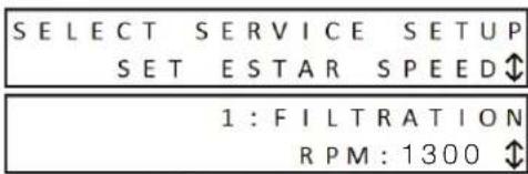
press to access the setting:
use the 🔒 key to set the speed (from 600 to 3450 rpm, per 10 rpm step),
then press MENU to validate.
e) Pump freeze protect

The pump measures the running motor temperature and estimates the water temperature.
It activates the "eStar" speed if the temperature is too low, to protect the pump from freezing. This setting is used to set the anti-freeze cycle time.
WARNING
Freeze protection is intended to protect equipment and plumbing for short periods of freezing only. It does this by activating the filtration pump and circulating the water to prevent freezing inside equipment or plumbing. Freeze protection does not guarantee that equipment will not be damaged by extended periods of freezing temperatures or power outages. In these conditions, the pool should be shut down completely (for example, drained of water and closed for the winter) until warmer weather exists.
The pump must be protected and properly winterized when freezing temperatures are expected. Allowing the pump to freeze will cause severe damage and will void the warranty.

press to access the setting:
use the ▲ or key to set the time (from 0 minutes to 8 hours, per 30 minute
step, then press MENU to validate.
To deactivate the function, set the time to "0:00".
f) Pump type

This setting is used to determine the maximum authorised pump speed depending on the selected type. It is recommended not to change this setting to keep optimum pump performances.

press to access the setting:
use the ☐ key to select "ePUMP 60Hz" (maximum speed by default = 3450 by default = 2850 rpm), then press ☐ to validate.
g) Display power usage

You can display the pump's electricity consumption while running (in Watts). This setting is only displayed on the screen when the pump is running.

press MENU to access the setting:
use keys for to select "YES" or "NO" then press to validate MENU
To deactivate the function press "NO".
When the function is active, the user interface alternatively displays:
2 : SPEED 2 1 2 : 3 0 PM RPM : 1 0 0 0 ↑ and
2 : SPEED 2 1 2 : 30 PM PWR : 58W
h) Set minimum limit

This is used to limit the pump's minimum operating speed. The user will no longer be able to set the pre-defined speeds 2, 3, 4, 5, 6, 7 and 8 slower than this speed. The default speed is 600 rpm.
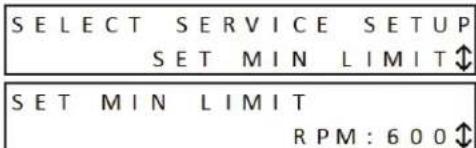
press to access the setting:
use the 🔒 key to set the speed (from 600 to 3450 rpm, per 10 rpm step),
then press MENU to validate.
i) Set maximum limit

This is used to limit the pump's maximum operating speed. The user will no longer be able to set the pre-defined speeds 2, 3, 4, 5, 6, 7 and 8 faster than this speed. The default speed is 3450 rpm.

press to access the setting:
use the 🔒 key to set the speed (from 600 to 3450 rpm, per 10 rpm step),
then press MENU to validate.
4. Maintenance
4.1 Maintenance instructions
WARNING
It is recommended to carry out general servicing of the appliance on winterizing and restarting in order to check it is in good working order and maintain its performances, as well as to prevent certain possible defects.
These actions are the user's responsibility and must be carried out by a qualified technician.
- Make sure no foreign bodies enter the pump or the electric compartment.
- Clean the outside of the appliance, do not use solvent based products.
- Check that the use interface is in working order.
- Check that metal casing is connected to the ground.
- Check the tightness of the electric wire connections and the cleanliness of the electric control box.
- Clean the basket, the lid and its seal regularly.
- Make sure the basket is correctly fitted, otherwise it could prevent the hermetic closure of the lid.
4.2 Winterizing
WARNING
Freeze protection is intended to protect equipment and plumbing for short periods of freezing only. It does this by activating the filtration pump and circulating the water to prevent freezing inside equipment or plumbing. Freeze protection does not guarantee that equipment will not be damaged by extended periods of freezing temperatures or power outages. In these conditions, the pool should be shut down completely (for example, drained of water and closed for the winter) until warmer weather exists.
The pump must be protected and properly winterized when freezing temperatures are expected. Allowing the pump to freeze will cause severe damage and will void the warranty. To avoid condensation damaging the appliance, do not cover it hermetically.
- If the pump is located beneath the water level, shut off the isolation valves on the admission and discharge.
- Drain the pump (using the 2 drainage screws) and the hydraulic circuit by following the pool manufacturer's instructions.
- Remove the 2 drainage screws and put them aside to be refitted when the pool is restarted.
-
It is recommended to disconnect the electric power cable, and then to unscrew the hydraulic fittings to store the pump in a dry location protected from freezing.
-
Troubleshooti ng
| Malfuncti on Possible causes Soluti ons | ||
| The water is not circulati ng properly | Dirty basket and/or fi lterIncorrectly set valves | Clean the basket and/or fi lterAdjust the valves |
| There are air bubbles in the basket | Air is blocked in the circuitThe pool water level is too lowThe pump lid is incorrectly sealed | Purge the circuitCheck the water level, add water if necessaryCheck the cover and seal are airti ght |
| There are air intakes | The fi tti ngs are not properly ti ghtenedThe fi tti ng seals are incorrectly positi oned or damaged | Tighten the fi tti ngsChange the seals |
| There is no air in the circuit but the pressure is low | There is debris stuck inside the pump | Remove the debris manually by opening the lid and removing the basketIf debris remains, the pump will need to be dismantled to access the impellerWarning: these operati ons must be carried out by a qualifi ed technician |
| If there is no debris in the pump but the pressure is low | The pump impeller and diff user are wornElectric problemWorn seal | Have the impeller and diff user replaced by a qualifi ed technicianHave the electric installati on checked by a qualifi ed technicianReplace the seal |
| There is a water leak between the motor and the pump body | The mechanical packing is damaged or defective | Replace the mechanical packingWarning: these operati ons must be carried out by a qualifi ed technician |
| Malfuncti on Possible causes Soluti ons | ||
| The pump heats and someti mes switches off | Bad air circulati on around the motorBad electric connecti onsCurrent variati ons are too high | Check that the motor is correctly venti lated for coolingCheck the electric connecti onsHave the electric circuit checked by a qualifi ed technician |
| The pump will not start | There is no power supply to the pumpThe user interface cable is damagedThe pump address is incorrectly confi guredThe user interface displays an error message | Check the electric connecti onsCheck the conditi on of the user interface cableCheck the switch confi gurati ons (see §2.4.4) |
| There is nothing on the user interface or the external controller display | The pump address is incorrectly confi guredThe user interface cable is damaged, or has a loose connecti on | Check the switch confi gurati ons (see §2.4.4)Check the conditi on of the user interface cable |
| The user interface displays "PUMP NOT CONNECTED" | The user interface cable is damaged, or has a loose connecti onThe pump address is incorrectly confi gured | Check the conditi on of the user interface cableCheck the switch confi gurati ons (see §2.4.4) |
6. Registering the product
Register your product on our website: www.zodiac.com.au
- You will be the first to be informed of new Zodiac® products and special offers,
- You can help us to constantly improve our product quality.

Dimensions
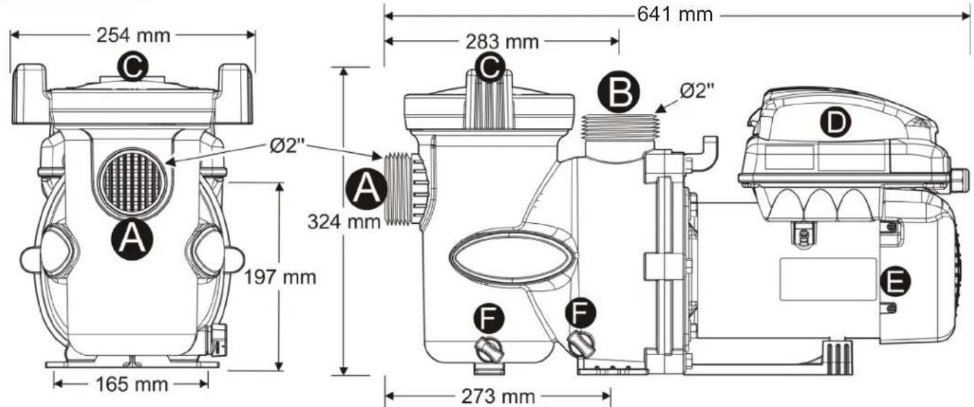
Weight pump only: 17kg
Description
| A | Water admission |
| B | Water discharge |
| C | Pre-filter cover |
| D | User interface |
| E | Pump motor |
| F | Drain |
Performance graphs
FLOPRO VS 1.5 PUMP PERFORMANCE

line
| Liters/Minute (LPM) | 1250 RPM | 1800 RPM | 2400 RPM | 3000 RPM | | ------------------- | -------- | -------- | -------- | -------- | | 0 | 4.0 | 8.5 | 15.0 | 23.5 | | 200 | 1.0 | 4.0 | 11.0 | 19.0 | | 300 | 0.5 | 2.0 | 7.0 | 14.0 | | 400 | 0.2 | 1.0 | 4.0 | 8.0 | | 500 | 0.1 | 0.5 | 2.0 | 4.0 |Zodiac® FloPro Pool Pump Warranty
This Zodiac FloPro Series pool pump was carefully inspected before shipment from our warehouse. Upon unpacking, if any part is missing or found to be defective, please notify your dealer immediately.
Zodiac Group Australia Pty Ltd warrants the FloPro Series pool pump to be free from defects in materials and workmanship for a period of 3 years from date of purchase and 1 year on the mechanical seal for domestic applications. The warranty is applicable to the asia pacific region only.
This limited warranty excludes the following;
1) Replacement of parts which fail or become defective as a result of improper installation, negligence, misuse, abuse or tampering by unauthorized personnel.
2) Lightning or other acts of nature
3) Damage or malfunction of the unit resulting from improper water chemistry balance.
4) Scaling, freezing, or other conditions causing inadequate water circulation
5) Normal wear and tear
6) Inadequate ventilation
7) Running the pump dry
8) The use of non-factory authorized parts or accessories in conjunction with the product(s)
9) Operating the product(s) at water flow rates outside the published minimum and maximum specification.
To obtain warranty replacement or repair, the unit should be returned to the place of purchase. When submitting a claim, always supply serial number, evidence of purchase date, retailer and brief description of the problem/ defects encountered. Zodiac Group Australia Pty Ltd reserves the right to repair or replace all defective or worn parts covered by this warranty, through the place of purchase. Where the purchaser sends the units to the place of purchase by post or courier for repair or replacement, freight is the responsibility of the purchaser.
Zodiac and/or its authorized service centres may seek reimbursement of any costs incurred by them (including labour charges) when the product or relevant part is found to be in good working order or if the warranty claim is invalid.
Zodiac Group Australia Pty Ltd assumes no responsibility for any warranties or representations made by other individuals or businesses beyond the express terms contained in this limited warranty.
The warranty gives you specific legal rights, and you may also have other rights which vary from state to state. This warranty will remain the property of Zodiac Group Australia Pty Ltd.
Commercial Applications
The Zodiac FloPro series pool pump is warranted for a period of 12 months for all parts from the date of the first consumer purchase. Should any parts fail as a result of such defects within the 12 month period, Zodiac will warrant it free of charge. Any associated travel charges are not included.
Notes
Notes
Zodiac Group Australia Pty Ltd
ABN 87 002 641 965,
219 Woodpark Rd,
Smithfield NSW 2164, Australia
Ph: 1300 763 021
ZODIAC ^® is a registered trademark of Zodiac International, S.A.S.U., used under license. All trademarks referenced herein are the property of their respective owners.
©2014 Zodiac Pool Systems, Inc. H0485400 Rev B

- WARNING
- Important Safety Instructions
- READ AND FOLLOW ALL INSTRUCTIONS
- CAUTION
- SAVE THESE INSTRUCTIONS
- Contents
- Information before installing
- General delivery terms and conditions
- Contents
- Technical specifications
- Installation
- Selection of the location
- Installing the appliance
- Hydraulic connecti ons
- Electric connecti ons
- ELECTRICAL SHOCK HAZARD
- a) Default Dip Switch Positions
- c) AquaLink TRi connecti on opti on
- d) External "on/off" switch connection option
- Use
- User interface presentation
- Checks before starting up
- RISK OF SUCTION ENTRAPMENT HAZARD, WHICH, IF NOT AVOIDED, CAN RESULT IN SERIOUS
- Start up the appliance
- User interface settings and use
- Locking/unlocking the keyboard
- Starting or stopping a speed
- User menu
- a) Set the time
- b) Label speeds
- c) Display lighting
- d) Language
- e) Run duration
- f) Password protection
- Timeclock
- Service menu
- b) Last fault
- c) Priming
- d) Set "eStar" speed
- e) Pump freeze protect
- f) Pump type
- g) Display power usage
- h) Set minimum limit
- i) Set maximum limit
- Maintenance
- Maintenance instructions
- Winterizing
- Registering the product
- Performance graphs
- Zodiac® FloPro Pool Pump Warranty
- Commercial Applications
- Notes
Brand : ZODIAC
Model : FloPro VS
Category : Pump