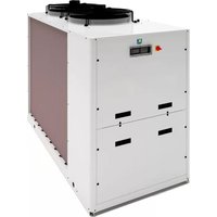
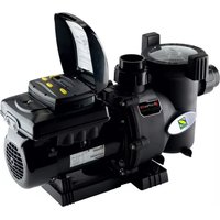
Z900 - Pump ZODIAC - Free user manual and instructions
Find the device manual for free Z900 ZODIAC in PDF.


| Product Type | Pool Pump |
| Brand | Zodiac |
| Model | Z900 |
| Power | 1.5 HP |
| Voltage | 230 V |
| Flow Rate | 300 L/min |
| Max Head | 10 m |
| Inlet/Outlet Size | 50 mm |
| Weight | 15 kg |
| Dimensions (LxWxH) | 400 x 250 x 300 mm |
| Material | Reinforced Thermoplastic |
| Operation | Continuous duty |
| Protection Class | IP55 |
| Noise Level | 70 dB(A) |
| Warranty | 2 years |
| Manual Languages | Multiple (see website) |
Frequently Asked Questions - Z900 ZODIAC
User questions about Z900 ZODIAC
0 question about this device. Answer the ones you know or ask your own.
Ask a new question about this device
Download the instructions for your Pump in PDF format for free! Find your manual Z900 - ZODIAC and take your electronic device back in hand. On this page are published all the documents necessary for the use of your device. Z900 by ZODIAC.
USER MANUAL Z900 ZODIAC
natural_image
Technical line drawing of a heat exchanger unit with cooling fans and cooling fins (no text or labels)Instructi ons for installati on and use - English Heat pump Translati on of the original instructi ons in french

natural_image
Technical line drawing of a large industrial cooling unit with heat exchangers and cooling fans (no text or symbols)More documents on: www.zodiac-poolcare.com
EN


WARNINGS
- Failure to respect the warnings may cause serious damage to pool equipment or cause serious injury, even death.
- The appliance is intended to be used only for swimming pools and spas; it must not be used for any purpose other than that for which it has been designed.
- It is important that the equipment is operated by competent and qualified (both physically and mentally) people who have previously received the instructions for use. All persons not meeting these criteria must not approach the appliance in order to avoid exposure to dangerous elements.
- Keep the appliance out of the reach of children.
- The device must be installed by a qualified technician according to the manufacturer's instructions and in compliance with local regulations. The installer is responsible for installation of the equipment and for compliance with national installation regulations. Under no circumstances can the manufacturer be held liable in the event of failure to comply with applicable local standards.
- Incorrect installation and/or use may cause serious damage to property or serious injuries (possibly resulting in death).
- Any equipment, even carriage and packing paid, travels at the consignee's risk. The consignee should enter any reservations in writing on the carrier's delivery note, if there is any evidence of transport damage (and confirm them by recorded delivery letter to the carrier within 48 hours). In the event of a device containing coolant fluid that has been tipped over, issue your reservations to the carrier in writing.
- If the appliance suffers a malfunction, do not try to repair it yourself; contact a qualified technician.
• Refer to the warranty conditions for details of the permitted water balance values for operating the appliance. - Eliminating or shunting one of the safety devices automatically voids the warranty, as does the replacement of parts using parts not manufactured by ourselves.
- Do not spray insecticide or any other chemical (inflammable or non-inflammable) in the direction of the appliance, as this may damage the body and cause a fire.
- Heat pump, filtration pump and filter appliances are compatible with all types of water treatment.
- Do not touch the fan and/or moving parts or insert a rod or your fingers in the vicinity of the moving parts while the appliance is in operation. The moving parts may cause severe injury, including death.
- The electrical supply to the appliance must be protected by a dedicated 30mA differential residual current protection device, complying with the standards and regulations in force in the country where it is installed.
- Do not use an extension cord to plug the appliance into; plug it directly into a proper wall socket or outlet.
- Before carrying out any operations, check that:
The voltage indicated on the maker's plate of the appliance corresponds to the mains voltage,
- The power grid is adapted to the power requirements of the appliance, and is properly grounded.
The plug (where applicable) is suitable for the socket.
- In the event of abnormal function or the release of odours from the appliance, turn it of immediately, unplug it from its power supply and contact a professional.
- Before any access to the appliance for any required service or maintenance, ensure that it is switched off and disconnected from the power supply. In addition to any other equipment connected to the appliance, and that the heating priority (where applicable) is deacti vated.
- Do not disconnect and reconnect the appliance to the power supply when in operation.
- Do not pull on the power cord to disconnect it from the power supply.
- Do not attempt to carry out any service or maintenance with wet hands or while the appliance is wet.
- Clean the terminal board or the power supply socket before connection.
- For any component or sub-assembly containing a battery: do not recharge or dismantle the battery, or throw it into a fire. Do not expose it to high temperatures or direct sunlight.
• In stormy weather, unplug the appliance to prevent it from suffering lightning damage. - Do not immerse the appliance in water (with the exception of cleaners) or mud.
- Do not discharge R410A or R407C fluid into the atmosphere. These are fluorinated greenhouse effect gases, covered by the Kyoto Protocol, with a Global Warming Potential (GWP) = 2088 for R410A (Directi ve EC 842/2006).
- According to French decree No. 2015-1790, if the appliance has more than 5teq CO2 of refrigerant gas (refer to manufacturer specifications), the cooling circuit must be checked for leakage at least once a year. This operation must be carried out by a certified cooling appliance specialist.
The heat pumps comply with Directive 2014/68/EU (PED) via Annex III, Module D1, and certified as such by the third-party, independent Noti fi ed Body, ICIM No. 0425.
Additi onal considerati ons in relati on to this Directi ve
Installati on and maintenance
The unit may not be installed close to combustible materials, or the air duct inlet of an adjacent building
With some devices, it is essential to fit protecti on grids if the unit is installed in an area with uncontrolled access.
During installation, troubleshooting and maintenance, pipes may not be used as steps: the pipe could break under the weight, spilling refrigerant and possibly causing serious burns.
When servicing the appliance, the composition and state of heat carrying fluid must be checked, as well as the absence of any refrigerant.
During the annual unit sealing test in accordance with applicable legislation, the high and low pressure switches must be checked to ensure that they are securely fastened to the coolant circuit and that they cut-off the electrical circuit when tripped.
During maintenance work, ensure there are no traces of corrosion or oil around cooling components.
Before beginning work on the cooling circuit, stop the device and wait for a few minutes before fitting the temperature and pressure sensors. Some elements such as the compressor and piping may reach temperatures in excess of 100irc C and high pressures with the consequent risk of severe scalding.
Troubleshooti ng
All soldering work must be carried out by a someone qualified to do so.
Replacement pipes must always be made of copper in compliance with standard NF EN 12735-1.
Leak detection, pressure test:
- never use oxygen or dry air, risk of fire or explosion,
- use dry nitrogen or the mixture of nitrogen and refrigerant indicated on the information on plate,
- the test pressure for both the high and low pressure circuits must not exceed 42 bar (for R410A) in the case the device is
equipped with the optional pressure gauge.
The high pressure circuit pipes are made of copper and have a diameter equal to or greater than 1"5/8. A certificate as indicated in §2.1 in compliance with standard NF EN 10204 will be requested from the supplier and filed in the facility's technical documentation. Technical data relative to the safety requirements of the various applicable directives must be indicated on the information plate. All this information must be recorded in the unit's installation manual, which must be kept in the technical file of the unit: model, code, serial number, maximum and minimum OT, OP, year of manufacture, EC label, manufacturer's address, refrigerant and weight, electrical parameters, thermo-dynamic and acousti c performances.
Recycling

This symbol means that your appliance should not be disposed of with other rubbish. It should be selectively sorted so that it can be re-used, recycled or transformed. If it contains any substances that may be harmful to the environment, these will be disposed of or neutralised.
Contact your retailer for recycling information.

- Before you do anything with the device, it is vital that you read this installation and user manual, as well as the "warnings and warranty" booklet delivered with the device. Failure to do so may result in material damage or serious or fatal injury and will devalidate the warranty.
- Keep and pass on these documents for later consultation during the device's life time.
- It is prohibited to distribute or modify this document in any way without authorisation from Zodiac®.
- Zodiac® is constantly developing its products to improve their quality; therefore, the information on contained in this document may be modified without notice.
CONTENTS

1 Installati on 3
1.1 I Selecti ng the locati on 3
1.2 | Hydraulic connections 4
1.3 | Electricity supply connections 5
1.4 | Opti onal connecti ons 6

② Use 7
2.1 | Operating principle 7
2.2 | User interface presentation 7
2.3 | Operating 8
2.4 | Additional user functions 8
2.5 | Change to cooling mode 9

3 Maintenance
3.1 | Winterising 10
3.2 | Servicing 10

4 Troubleshooti ng
4.1 | Device behaviour 11
4.2 | Displays 13
4.3 | Wiring diagram 15

5 Characteristi cs
5.1 | Descripti on 16
5.2 I Technical specifi cati ons 17
5.3 | Dimensions and marking 18

Tip: to make it easier to contact your dealer
- Write down your dealer's contact details to help you find them more easily and fill in the "product" information on the back of the manual; your dealer will ask you for this information.

1 Installation
1.1 I Selecti ng the locati on
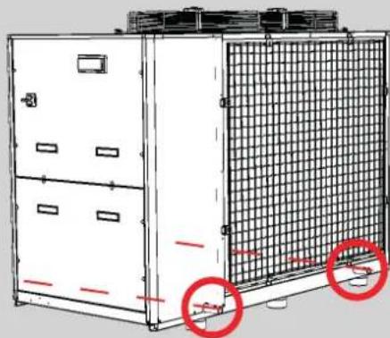
- The device must be installed at a minimum distance from the pool's surrounding edge. This distance is determined by the electrical standards which apply in the installati on country. - Use the holes provided (∅ 40mm) when lifting the device. A lifting kit is available as an accessory (see § "5.1 I Descripti on" »).

natural_image
Technical line drawing of a mechanical device with internal grid structure and two red circles highlighting features (no text or symbols)EN
- Install the device outdoors; provide free space around it (see § "1.2 | Hydraulic connections").
• Install the 6 anti-vibration studs under the base and place the device on a stable, solid and level surface.

natural_image
Diagram of a multi-panel container with red circles highlighting circular ports, no text or symbols present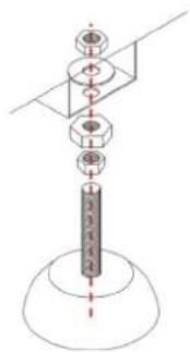
Positi on of the anti -vibrati on studs as seen from under the device Stud mounting order
- This surface must be able to bear the weight of the device (in particular in the case of installation on a roof, a balcony or any other support). We recommend that you install the device on a slab to channel the condensation away.
The device must not be installed:
- With the blowing towards a permanent or temporary obstacle (awning, brushwood, etc.) less than 5 metres away,
- Within range of water or mud jets, sprays or run-off (take the effect of the wind into account),
- Near a heat source or flammable gas,
• Near high frequency equipment, - In a locati on where it would be subject to snow build-up,
- In a location where it might be flooded by the condensation produced by the device when operating.

Informati on: condensati on drainage
Cauti on, your device may evacuate several litres of water per day, caused by condensati on from the water present in the air.

Tip: reduce any noise annoyance from your heat pump
- Do not install it under or towards a window.
- Do not ti it it towards your neighbours.
• Install it in a clear space (the sound waves are reflected on surfaces).
• Install an acousti c screen around the heat pump, respecting the distances. - Install 50cm of flexible PVC pipe at the heat pump water inlet and outlet (to stop the transmission of vibrations).
1.2 I Hydraulic connecti ons
- The device will be connected with a ∅63 or ∅90 PVC pipe, using the connectors supplied, to the pool's filtration circuit, after the filter and before the water treatment.
- Respect the directi on of hydraulic connecti on.
- A by-pass must be installed to make it easier to work on the device.

Connecti on to a standard fi Itrati on circuit
A: water inlet valve
B: by-pass valve
©: water outlet valve
D: water inlet adjustment valve (opti onal)
E: water outlet adjustment valve (opti onal)
* minimum distance

1.3 I Electricity supply connecti ons

- Incorrectly tightened terminals may cause the terminal unit to heat up and invalidate the warranty.
- Before any work inside the device, you must disconnect the electricity supply to avoid the risk of electric shock which may cause material damage, serious injury or even death.
-
Only a qualified and experienced technician is authorised to carry out cabling in the equipment or to replace the supply cable.
-
The heat pump's electrical supply must be provided through a properly selected and rated and circuit breaking device (not supplied) complying with the standards and regulations in force in the country where it is installed.
- The device is provided for connection to a general power supply with a TT and TN.S neutral regime.
- Electrical protection: by circuit breaker (D curve) (for calibre, see § "5.2 I Technical specifications"), with a 30 mA dedicated Ground Fault Circuit Interrupter (GFCI).
• Additional protection may be required during installation to guarantee the II overvoltage category. - The electricity supply must correspond to the voltage indicated on the device's information plate.
- The electricity supply cable must be protected from any damage such as sharp edges, abrasion, excessive heat that may damage or crush it.
- The equipment must be reliably connected to an appropriate earthing (grounding) point.
- The electrical connecti on lines must be fi xed.
- Use the gland to pass the supply cable into the device.
- Use the supply cable (RO2V type) adapted for outdoor or buried use (or run the cable into a protection duct) with an external diameter of between 16 and 22mm.
• We recommend burying the cable at a depth of 50 cm (85 cm under a road or path) in an electrical duct (ribbed). - If this buried cable meets another cable or pipe (communication, gas, water, etc.), there must be more than 20 cm between them.
- Connect the supply cable to the connecti on terminal unit inside the device.

1-3-5: phases
7: neutral


- Check that the phases are in the right order: the LED on the phase order controller (RSF) must be on fixed.
1.4 I Opti onal connecti ons

Connecting the "Remote on/off command" and "Alarm" options:
- Any access to the electrical enclosure and mains terminal area presents a risk of electrical shock which can result in electrocuti on, property damage, and serious injury, including loss of life. Be sure to disconnect the device from the power source before accessing the electrical enclosure of terminal area.
- Any incorrect connection to the main terminal unit may damage the device and void its warranty.
- Use cables with a secti on of at least 2x1.5mm 2 , RO2V type and with a diameter between 8 and 13mm.
- Use the gland to pass the cables into the device. The cables used for the options and the supply cable must be kept separate (risk of interference) using a collar inside the device just after the glands.
1.4.1 "Remote control" opti on
- This option lets you manage the device remotely. To do so, use the remote control kit available as an accessory.
- For the connection, consult the manual supplied with the kit.
- If a remote control device is to be installed, provide an RS485 cable having a maximum length of 50 metres.
1.4.2 "Alarm" option
- This option enables a relay to be connected to the alarm contact to indicate a fault remotely.
- For the connection, connect the cable to the 24V terminal and to terminal "50". This is a dry-contact connection, is polarity-independent, and is rated 2 Amps, Max.

A: heat pump terminal unit
B: alarm contact relay
C: separate connecti on cable
1.4.3 Remote "on/off" control opti on
- This option enables the "on/off" button function to be transferred via a switch installed remotely.
- For this connection, remove the shunt between terminals 30 and 18. Then connect each of the two wires of the switch to each of these terminals. This connection is polarity independent and is rated 220-240V, 50Hz.

A: heat pump terminal unit
B: remote "on/off" switch
©: separate connecti on cable


Use
2.1 I Operating principle
Your heat pump uses the calories (heat) in the air to heat up your pool's water. The process to heat your pool's water to the temperature you want may take a few days as it depends on the weather conditions, your heat pump's power and the difference between the water temperature and the temperature you want. . The warmer and damper the air, the better your heat pump will perform.

Tip: improve your pool's temperature rise and maintenance
- Anti cipate and plan the use of your pool well enough in advance before you use it.
- For the temperature rise, set the water circulati on to conti nuous operati on (24/24).
- To maintain the temperature throughout the season, run "automatic" circulation for at least 12 hours/day (the longer this time the longer the heat pump will have enough operating range to heat up).
• Cover the pool with a an appropriate pool cover (bubble canopy, canvas, etc.) to prevent heat loss. - Take advantage of a period with mild outdoor temperatures (on average >10°C at night); it will be even more effective if it runs during the warmest hours of the day.
- Keep the evaporator clean.
- Set the temperature you want and let the heat pump run (adjusting the setpoint to maximum will not heat the water more quickly).
2.2 I User interface presentation
| *28.01 | Water temperature |
| Back butt onAlarm deactivati on butt on | |
| Parameter access butt onEntry/display/validati on in a parameter butt on | |
| Single press: sensor value reading (see § “2.4.2 Sensor temperature reading”)5-second press: start/stop the device in heating mode (default mode)In the parameters menu:Butt on to navigate from the top in the parametersValue increase butt on | |
| Single press: sensor value reading (see § “2.4.2 Sensor temperature reading”)5-second press: start/stop the device in cooling mode (if acti vated)In the parameters menu:Butt on to navigate from the bottom in the parametersValue reduce butt on |
| Symbol | Designati on Fixed Flashing | ||
| Heati ng mode In operati on / | |||
| Cooling mode | In operati on / | ||
| Alarm | Alarm active | / | |
| Condenser anti -freeze resistance | In operati on | / | |
| Defrosti ng | In operati on | In operati ng request | |
| Fan | In operati on | / | |
| Compressor | In operati on | / | |
| 1 | Compressor (1 + 2 on TD50) | In operati on | In operati ng request |
2.31 Operating
- Check that there are no tools or other foreign objects in the machine.
- The panel that provides access to the electrical enclosure must be properly secured in place.
- Set the valves as follows: valve B wide open, valves A, C, D and E closed

A: water inlet valve
B: by-pass valve
©: water outlet valve
D: water inlet adjustment valve (opti onal)
E: water outlet adjustment valve (opti onal)

- An incorrect by-pass setting may cause the heat pump to malfunction.
- Ensure that the hydraulic connections are enough tightened and correctly so that there are no leaks.
- Ensure that the device is fully stable.
- Set the water circulati on running.
- Close valve B gradually so that the filter pressure is increased by 150 mbars (0.150 bars).
- Open valves A, C and D fully then valve E by half (the air which has built up in the heat pump condenser and the filtrati on circuit will bleed out). If valves D and E are not present, open valve A wide and close valve C by half.
- Connect the power supply to the heat pump.
- Press and hold for 5 seconds to start the appliance in heating mode.
After the start-up steps for your heat pump:
- Shut down the water circulation temporarily (by stopping the filtration or closing valve B or C) to check that you device stops after a few seconds (via the activation of the flow switch).
2.4 I Additi onal user functi ons
2.4.1 Adjusting the temperature setpoint (in heating mode)
The setpoint temperature is set by default to 28°C.
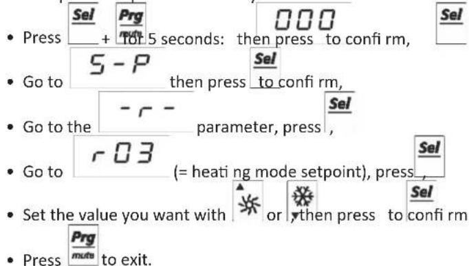
The heat pump stops automati cally when the pool reaches the required temperature.
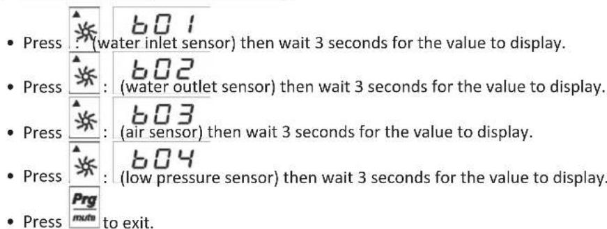
2.4.2 Sensor temperature reading
2.5 I Change to cooling mode
2.5.1 Connecti on to be made to change to cooling mode
The device operates either in heating mode or in cooling mode.
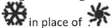
By default, the heat pump is in heating mode; to change to cooling mode, install a shunt between terminals 19 and 30
on the terminal unit. The device must then display in place of
2.5.2 Adjusting the temperature setpoint (in cooling mode)
The setpoint temperature is set by default to 28irc C.
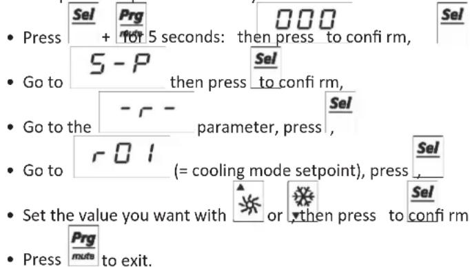
The heat pump stops automati cally when the pool reaches the required temperature.

3 Maintenance
3.1 I Winterising

- Winterising is recommended if the device is not used for a long period.
- If only the heat pump is wintered, the device may be kept frost-free thanks to the resistances on the condensers and the compressor(s); in this case, keep it powered with electricity. There will be no need to drain the condensers.
-
To avoid damaging the equipment due to condensati on, do not fully cover it.
-
Disconnect the electrical supply.
- Open valve B,
- Close valves A and C and open valves D and E (if present),
- Make sure that there is no water circulating in the heat pump,
- Drain the water from the condensers (risk of freezing) by unscrewing the two water inlet and outlet connectors on the back of the heat pump,
- In the case of full wintering for the pool (complete shutdown of the filtration system, bleed the filtration circuit or even pool drainage): insert the two plugs provided and, where necessary, tighten the two connectors by one turn to prevent any foreign body from penetrating the condenser,
- In the case of wintering for the heat pump only (shutdown of the heating only, but the filtration keeps running): do not tighten the connectors but instead add 2 caps (provided) on the condensers water inlets and outlets.
3.21 Servicing

- It is recommended that the equipment is fully serviced at least once a year to ensure proper operation, maintain performance levels and possibly prevent potential failures.
- Depending on the legislation in the country where the device is installed, regular cooling system checks may be required. Contact your technician.
- These operations are carried out at the user's expense and some must be carried out by a qualified technician, as detailed below.
3.2.1 User maintenance
- Make sure that the venti lati on grates are not blocked in any way.
- Clean the evaporator (for location see § "5.3 | Dimensions and marking") using a soft brush and a fresh water spray (disconnect the power cable); do not fold over the metal wings.
- Do not use a high pressure jet. Do not spray with rain water, salt water or water which is full of minerals.
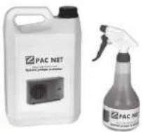
- Clean the outside of the device; do not use any solvent-based products. Zodiac can provide you with a specific cleaning kit as an option: the PAC NET, see § "5.1 | Descripti on".
3.2.2 Maintenance to be carried out by a qualified technician
- Check that the regulati on is operati ng correctly.
- Check that the condensation flows freely and without any blockage when the device is operating; service as needed.
- Check for proper operation of all safety and protective mechanisms and devices; service as needed.
- Ensure that the appliance and all its dead metal components are properly connected to earth (ground).
- Make sure that the electrical cables are correctly tightened and connected and that the electrical unit is clean.

4 Troubleshooting

- Before you contact your reseller, please carry out these few simple checks using the following tables if a problem occurs.
- If the problem continues contact your reseller.
• : Acti ons only to be carried out by a qualifi ed technician

4.1 I Device behaviour
| The device does not start heating straight away | On start-up, the device remains "paused" for 1 at 6 minutes before it starts operating; the compressor number(s) fl ash.When the setpoint temperature is reached, the heat pump stops heating: the water temperature.It may be that the heat pump has detected an operating fault (see § "4.2 I Displays").If you have checked these points and the problem persists: contact your reseller. | |
| The device is draining water | Oft en called condensati on. This water is the moisture contained in the air which condenses on contact with certain cold mechanisms in the heat pump, especially on the evaporator. The more damp the air, the more condensati on your heat pump will produce (your device may drain several litres of water per day).To check that the water is not coming from a leak in the pool circuit on the heat pump, shut down the heat pump and run the fl trati on pump for the water to circulate in the heat pump. If the water continues to flow through the condensati on drains after half an hour, there is a water leak in the heat pump; contact your reseller. | |
| The evaporator is iced over | Your heat pump will soon switch to its defrost cycle to melt the ice.If your heat pump cannot manage to deice its evaporator, it will stop itself; this means that the outdoor temperature is too low (below -12 °C). | |
| The device is "smoking" | This may occur when it is in a defrost cycle and the water is converted to gas. | |
| The device is not working | If there is no display, check the supply voltage and the general protecti on fuses.When the setpoint temperature is reached, the heat pump stops heating: the water temperature is higher than or equal to the setpoint temperature.When the water flow rate is zero or is not enough, the heat pump stops: check that the water is circulating correctly in the heat pump (fault displayed).The heat pump stops when the outdoor temperature is too low (fault displayed).It may be that the heat pump has detected an operating fault (see § "4.2 I Displays"). | |
| The device is working but the water temperature does not increase | Set the fl trati on 24/24 and close the cover or shutt er if the pool has one.Check that the automatic filling valve (if present) is not stuck in open position; this will keep supplying cold water into the pool and will prevent the temperature from rising.There is too much heat loss as the air is cool. Install a heat insulated cover on your pool.The heat pump is unable to capture enough calories as its evaporator is clogged with dirt. Clean it to restore its performances (see § "3.2 I Servicing").Check that the external environment is not hindering the heat pump (see § "1 Installati on").Check that the heat pump is the right size for this pool and its environment. | |
| The device trips the circuit breaker | Check that the circuit breaker is correctly dimensioned and that the cable secti on used is the right one (see § "5.2 I Technical specifi cati ons").The supply voltage is too low; contact your electricity supplier. | |
| Behaviour Possible causes Soluti ons | ||
| The device does not start working | No external signal | Bleed the circuit,Check that the flow switch (terminals 16 and 30) is operating correctly. |
| Delay between two compressor starts/ stops; the number(s) flash | Wait 5 minutes for the timer to provide the signal | |
| Interventi on on the general switch | Make sure that there are no short circuits on the cabling and the pump motor, fan, compressor and transformer windings | |
| No signal from the high or low pressure switch | see HP I and/or L P I | |
| Compressor defective | See "The compressor does not start working" | |
| The compressor does not start working | The compressor is defective or stuck | Replace the compressor |
| Power circuit open | Establish the cause of the protection in interventi onMake sure that there are no short circuits on the cabling and the pump motor, fan, compressor and transformer windings | |
| Motor thermal protection openCompressor operating under critical conditionsInsufficient load in the circuit, coolant leak | Make sure that the operating conditions conform to the specified limits.Check the cooling circuit with a leak detector after setting its pressure to 4 bars. Repair, create a vacuum and load. | |
| The compressor starts and stops repeatedly | Minimum pressure switch intervention | see L P I |
| Compressor remote switch defective | Check and replace if necessary | |
| Insufficient quantity of gas, leak possible | Check the cooling circuit with a leak detector after setting its pressure to 4 bars. Repair, create a vacuum and load. | |

- The fault number may vary according to the number of compressor(s) in the heat pump.
| Display Possible causes Soluti ons Resetti ng | |||
| ALT | Water temperature too low | Wait until the water temperature rises naturally | Automati c |
| d1 | Defrosti ng in progress Wait until the cycle is fi nished Automati c | ||
| dF1 | Error during defrosti ng: maximum ti me exceeded temperature not reached | The air temperature is too low, wait until the temperature rises naturally | Automati c |
| E1Water inlet sensor fault | Sensor is faulty or offl ine | Reconnect or change the sensor | Automati c |
| E2Water outlet sensor fault | Sensor is faulty or offl ine | Reconnect or change the sensor | Automati c |
| E3Air inlet sensor fault | Sensor is faulty or offl ine | Reconnect or change the sensor | Automati c |
| E4Pressure sensor fault | Sensor is faulty or offl ine | Reconnect or change the sensor | Automati c |
| EHSELS | Defecti ve connecti on or contacts openWrong voltage (outside tolerance limits ±5%) | Check the voltage and close the contacts | Automati c |
| EP6EEPROM fault | Problem saving parameters in the EEPROM non-volati le memory | Call a qualifi ed technician | Automati c |
| EPREEPROM fault | |||
| FLWater flow switch | Water flow problem | Make sure that there flow passing through the heat pumpCheck the flow switch | Automati c |
| CPHP | The water flow is too low, the difference between the b01 sensor (water inlet sensor) and the b02 sensor (water outlet sensor) must be lower than or equal to 6°C. | Increase the water flow | Automati c if fewer than 3 faults within the hour on TD20-TD30, otherwise manual |
| HP IHigh pressure or phase order controller fault | Cabling not respected on the appliance's supply terminals | Check that the RSF light is steady; if this is not the case, reverse the phases on the power supply terminal unit (device powered down) | Automati c |
| Electricity provider has changed the order of the phases | Contact the electricity provided to find out if your installati on has been modified. | ||
| Temporary disconnecti on of the power supply to one or more phases | |||
| No signal from the high pressure switch | Pressure switch defective, replace it if necessary | Manual of pressure sensor (positi on K, on § «5.3 I Dimensions and marking», page 18 | |
| Evaporator blocked, air flow too low | Remove the dirt on the evaporator and any obstacles preventing the air from passing through | ||
| Fan operati ng problem | Check that the fan is working correctly (replace it if necessary). | ||
| Water condenser scaled up | Clean the water condenser | ||
| Insufficient water flow | Increase flow using by-pass, check that the pool fi lter is not clogged | ||
| Air and water emulsion passed into the device | Check the pool's hydraulic circuit | ||
| Flow switch blocked | Check the flow switch | ||
| Electronic expansion valve closed | Valve expansion (or its driver) defect, replace it if necessary | ||
| Rotati on of the propeller not free | Declutter in front of the fan | Automati c | |
| Fan motor disconnected | Check the connector of the fan motor. If there is always the default, call a qualified technician. | ||
| Fan motor damaged | Call a qualified technician | ||
| Compressor thermal protecti on (kriwan) (only on TD30) | |||
| LP ILow pressure fault | No signal from the low pressure switch | Pressure switch defective, replace it if necessary | Automati c if fewer than 3 faults within the hour, otherwise manual |
| Leak on the cooling circuit | Call a qualified technician. | ||
| Evaporator blocked, air flow too low | Remove the dirt on the evaporator and any obstacles preventing the air from passing through | ||
| Frost present on the evaporati on battery + alternati ng fault | Check that the 4-way valve is operati ng correctly | ||
| Fan operati ng problem | Check that the fan is working correctly (replace it if necessary) | ||
| Electronic expansion valve closed | Valve expansion (or its driver) defect, replace it if necessary | ||

4.3 I Wiring diagram
| AP High pressure switch PD Diff erenti al pressure switch | |
| LP Low pressure switch RC Compressor resistance | |
| CF Fan control RG Regulator | |
| EVD Solenoid valve driver RS Anti -frost resistance | |
| FL Line fuse (not supplied) RSF Phase order controller | |
| SF Isolating switch with fuses | |
| IG General switch | |
| IL Line switch (not supplied) | |
| KLT Compressor contact | |
| KRAP High pressure relay | |
| MC Compressor motor | |
| MV Fan motor | |
| NTC Temperature sensor | |
| PCD MA PCDS Remote control (accessory) |
| SA | Ambient air sensor |
| SC Condensati on sensor | |
| SPR | Pressure sensor |
| T | Anti-frost heating thermostat |
| TR Transformer | |
| VE Solenoid valve | |
| VI Reversal valve | |
| WIN | Water inlet sensor |
| WOUT | Water outlet sensor |
EN

- The wiring diagram and the EU declaration are provided in a separate booklet from the installation and user manual.

5 Characteristics
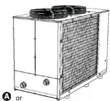
5.1 I Descripti on
natural_image
Technical line drawing of a heat exchanger unit with cooling fans and cooling fins (no text or symbols)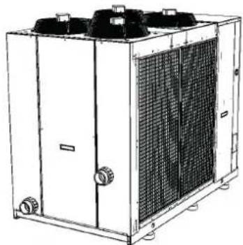
natural_image
Line drawing of a large industrial cooling unit with heat sinks and cooling fans (no text or symbols)B*

©

natural_image
Technical line drawing of a mechanical component with a flanged base and central hub (no text or symbols)D

* In the technical box
E

F

natural_image
Two parallel cylindrical rods with arrows indicating direction (no text or symbols)G
| A | Z900 TD20 TD30 TD50 | |||
| B | ∅63 connector (x2) | √ | √ | |
| ∅90 connector (x2) | √ | |||
| C Anti -vibrati on studs (x6) | √ | √ | √ | |
| D Wintering cap (x2) | √ | √ | √ | |
| E | Remote control | + | + | + |
| F | Lift ing kit | + | + | + |
| G | PAC NET (cleaning product) | + | + | + |

: supplied

: available as accessories
5.2 I Technical specifi cati ons
| Z900 TD20 TD30 TD50 | ||||
| Operati ng temperature range | air -12 to 38 °C | |||
| water 10 to 32 °C | ||||
| Voltage 380-415 V - 50Hz - 3-phase | ||||
| Acceptable variati on in voltage ± 5 % (during operati on) | ||||
| Polluti on class I | ||||
| Polluti on degree 2 | ||||
| Overvoltage category II | ||||
| Nominal absorbed intensity | A | 19.2 | 35 | 43.5 |
| Maximum absorbed intensity | A | 38 | 40 | 69 |
| Minimum cable section* | 5G10 (5x10mm2) | 5G16 (5x16mm2) | 5G16 (5x16mm2) | |
| Proof pressure | bar | 3 | 3 | 3 |
| Service pressure | bar | 1.5 | 1.5 | 1.5 |
| Head loss | bar | 0.15 | 0.15 | 0.15 |
| Nominal water flow | m3/h | 15 | 20 | 25 |
| Net weight | bar | 430 | 520 | 837 |
* Values provided for information on purposes for a maximum length of 20 metres (calculati on base: NFC15-100), must be checked and adapted to the installation conditions and standards of the installation country.
The information plate provides the following data (normally located on the appliance's external panel next to the evaporator):
- the appliance model and power
- the manufacturing date
- the main technical data
- the manufacturer
- the appliance serial number
The serial number is used to identify the technical characteristics and the components installed. The appliance cannot be correctly identified without this number.
Important: never remove this plate!
5.3 I Dimensions and marking

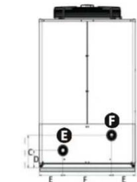
Fronts Z900 TD20 - TD30

natural_image
Diagram of two circular fan units labeled B, with no text or symbols on the fan surfacesTop Z900 TD20 - TD30
Side Z900 TD20 - TD30

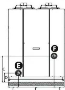
Fronts Z900 TD50

Top Z900 TD50
Side Z900 TD50
A: Base
B. Fan
©: Evaporator
D: Gland
E. Pool water inlet
F. Pool water outlet
G. Technical access door
H. User interface
①: "On/off" switch
J: Lift ing points
K: High pressure switch
| dimensions in mm | A* B* C D E* F* G* H* | |||||
| Z900 TD20Z900 TD30 | 73 1450 | 282 137 233 | 5 480 1965 | 951 | ||
| Z900 TD50 97 17 | 30 546 162 | 211 755 2091 | 1183 |
*Overall dimensions

- WARNINGS
- Installati on and maintenance
- Troubleshooti ng
- Recycling
- CONTENTS
- Installati on 3
- ② Use 7
- Maintenance
- Troubleshooti ng
- Characteristi cs
- Tip: to make it easier to contact your dealer
- Installation
- I Selecti ng the locati on
- Positi on of the anti -vibrati on studs as seen from under the device Stud mounting order
- Informati on: condensati on drainage
- Tip: reduce any noise annoyance from your heat pump
- I Hydraulic connecti ons
- I Electricity supply connecti ons
- I Opti onal connecti ons
- "Remote control" opti on
- "Alarm" option
- Remote "on/off" control opti on
- Use
- I Operating principle
- Tip: improve your pool's temperature rise and maintenance
- I User interface presentation
- Operating
- - An incorrect by-pass setting may cause the heat pump to malfunction.
- I Additi onal user functi ons
- Adjusting the temperature setpoint (in heating mode)
- Sensor temperature reading
- I Change to cooling mode
- Connecti on to be made to change to cooling mode
- Adjusting the temperature setpoint (in cooling mode)
- I Winterising
- Servicing
- User maintenance
- Maintenance to be carried out by a qualified technician
- Troubleshooting
- I Device behaviour
- I Wiring diagram
- Characteristics
- I Descripti on
- I Technical specifi cati ons
Brand : ZODIAC
Model : Z900
Category : Pump