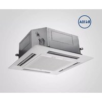
RZK140 - Air Conditioning Baxi - Free user manual and instructions
Find the device manual for free RZK140 Baxi in PDF.


| Product Type | Split Air Conditioner (Indoor + Outdoor Unit) |
| Brand | Baxi |
| Model | RZK140 |
| Cooling Capacity | 14,000 BTU/h (4.1 kW) |
| Heating Capacity | 14,000 BTU/h (4.1 kW) |
| Power Supply | 220-240 V, 50 Hz, Single Phase |
| Indoor Unit Dimensions (W x H x D) | 800 x 290 x 205 mm |
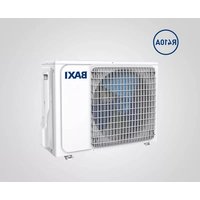
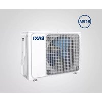
| Outdoor Unit Dimensions (W x H x D) | 800 x 600 x 300 mm |
| Indoor Unit Weight | 10 kg |
| Outdoor Unit Weight | 30 kg |
| Refrigerant | R32 |
| Airflow (High) | 500 m³/h |
| Noise Level Indoor (Low/High) | 25 / 45 dB(A) |
| Noise Level Outdoor | 55 dB(A) |
| Energy Efficiency (SEER) | 3.8 |
| Operating Modes | Cool, Heat, Dry, Fan, Auto |
| Key Functions | Timer, Sleep, Swing, Turbo, Eco, Self-Clean |
| Remote Control | Included (Infrared) |
| Filter Type | Washable Mesh Filter |
| Maintenance | Clean filters every 2 weeks; annual professional check |
| Safety Features | Overload protection, Anti-ice, Auto restart, Child lock |
| Spare Parts Available | Remote control, filter, drain hose, fan motor, compressor |
Frequently Asked Questions - RZK140 Baxi
User questions about RZK140 Baxi
0 question about this device. Answer the ones you know or ask your own.
Ask a new question about this device
Download the instructions for your Air Conditioning in PDF format for free! Find your manual RZK140 - Baxi and take your electronic device back in hand. On this page are published all the documents necessary for the use of your device. RZK140 by Baxi.
USER MANUAL RZK140 Baxi
natural_image
Exterior view of a modern office building (no signage)
natural_image
Front view of a white SAV air conditioner unit with ventilation grille and ventilation duct (no visible text or symbols)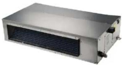
natural_image
Exterior view of a metallic industrial air conditioning unit with heat exchanger and cooling fins (no text or symbols visible)

natural_image
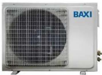
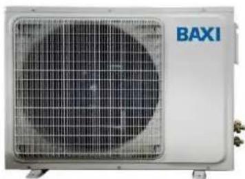
Exterior view of a BAXI air conditioner unit (no visible text or symbols on the device itself)
natural_image
Exterior view of a BAXI air conditioning unit with two circular fan blades (no text or symbols visible)| es | Aire acondicionado DC inverter MONO split con bomba de calor |
| Manual de inatalación | |
| RZNK50, RZNK70, RZNK100, RZNK120, RZNK140, RZNK160, RZNC50, RZNC70, RZNC100, RZNC120, RZNC140, RZNC160, RZND50, RZND70, RZND100, RZND120, RZND140, RZND160 | |
| RZT50, RZT70, RZT100, RZT120, RZT140, RZT160 |
TABLA DE CONTENIDOS
1. PRECAUCIONES DE SEGURIDAD....3
1.1. ADVERTENCIAS....3
1.2. PRECAUCIONES....3
1.3. ADVERTENCIA RAEE 4
2. ACCESORIO INCLUIDOS......4
2.1. UNIDAD EXTERIOR....4
2.2. UNIDAD INTERIOR....4
3. DATOS TÉCNICOS ....4
natural_image
Symbol of a trash bin crossed out by diagonal lines, representing waste sorting or disposal (no text or labels)2. ACCESORIO INCLUIDOS
2.1. UNIDAD EXTERIOR
natural_image
Technical line drawing of an air conditioning fan with internal blades and mounting bracket (no text or symbols)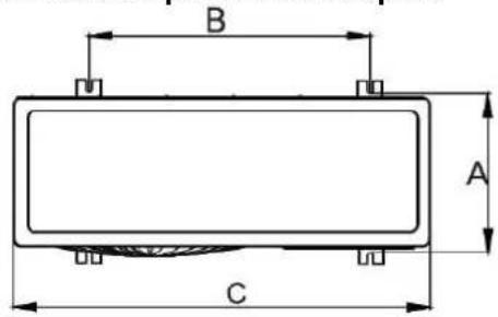
| MODELO | A | B | C | D |
| RZT50 | 288 | 546 | 799 | 545 |
| RZT70 | 320 | 632 | 900 | 700 |
| RZT100 | 388 | 610 | 940 | 1366 |
| RZT120 | 388 | 610 | 940 | 1366 |
| RZT140 | 388 | 610 | 940 | 1366 |
| RZT160 | 388 | 610 | 940 | 1366 |
natural_image
Technical line drawing of a three-tiered storage unit with dimension标注 (no text or symbols)| MODELO | A | B |
| 50 | 929 | 841 |
| 70 | 1280 | 1192 |
| 100 | 1631 | 1543 |
| 120 | ||
| 140 | ||
| 160 |
natural_image
Pure technical line drawing of a mechanical assembly without any text, numbers, or symbols
natural_image
Pure technical diagram of a mechanical or electrical component with no visible text, numbers, or symbols.4.3. INSTALACION DEL CONTROL POR CABLE
natural_image
Technical line drawing of a mechanical assembly with threaded components and a bolted joint (no text or symbols)| PIPE DIAMETER | TORQUE |
| 6.36mm (1/4") | 15-19 N m |
| 9.62mm (3/8") | 35-40 N m |
| 12.7mm (1/2") | 50-60 N m |
| 15.88mm (5/8") | 62-76 N m |
| 19.05mm (/") | 98-120 |
Sal B: BS____/BH____°C
natural_image
Exterior view of a modern recessed ceiling light fixture with a grid-patterned ventilation grille (no text or symbols visible)
natural_image
Front view of a white industrial air conditioner unit with ventilation grille and ventilation duct (no visible text or symbols)
natural_image
Exterior view of a metallic industrial air conditioning unit with heat exchanger and cooling fins (no text or symbols visible)

natural_image
Front view of a vintage medical or laboratory device with control panels and display (no visible text or symbols)
natural_image
Exterior view of a BAXI air conditioner unit (no visible text or symbols on the device body)
natural_image
Exterior view of a BAXI air conditioning unit with two circular fan blades (no text or symbols visible)| it | Climatizzatore d'aria MONO Split DC inverter in pompa di calore |
| Manuale di installazione e assistenza | |
| RZNK50, RZNK70, RZNK100, RZNK120, RZNK140, RZNK160, RZNC50, RZNC70, RZNC100, RZNC120, RZNC140, RZNC160, RZND50, RZND70, RZND100, RZND120, RZND140, RZND160 | |
| RZT50, RZT70, RZT100, RZT120, RZT140, RZT160 |
SOMMARIO
2. ACCESSORI INCLUSI....8
2.1. UNITA' ESTERNA....8
2.2. UNITA' INTERNA....8
3. DATI TECNICI....9
3.1. LIMITI DI FUNZIONAMENTO 9
3.2. CARATTERISTICHE TECNICHE....9
4. INSTALLAZIONE 16
4.1. INSTALLARE L'UNITA' ESTERNA 16
4.2 INSTALLARE L'UNITA' INTERNA....19
4.2.1. CANALIZZATA [RZND(50/70/100/120/140/160)] 19
4.2.2. A CASSETTA [RZNK(50/70/100/120/140/160)] 21
4.2.3. A PAVIMENTO/SOFFITTO [RZNC(50/70/100/120/140/160)] .....25
4.3. INSTALLARE IL CONTROLLO A FILO A PARETE....26
5. TUBAZIONE DEL GAS REFRIGERANTE....27
5.1.COLLEGAMENTO DEI TUBI 27
5.2. PROVA DI TENUTA....28
5.3. ESECUZIONE DEL VUOTO....28
5.4. CARICA DEL GAS REFRIGERANTE....29
6. COLLEGAMENTI ELETTRICI ....30
natural_image
Simple line drawing of a trash bin with diagonal lines crossing it, no text or symbols present.2. ACCESSORI INCLUSI
2.1. UNITA' ESTERNA
| QUANTITA' | |||||||
| N° | NOME | RZT50 | RZT70 | RZT100 | RZT120 | RZT140 | RZT160 |
| 1 | Manuale installatore | 1 | 1 | 1 | 1 | 1 | 1 |
| 2 | Connettore scarico | 1 | 1 | 1 | 1 | 1 | 1 |
| 3 | Dadi rame | 2 | 2 | 2 | 2 | 2 | 2 |
2.2. UNITA' INTERNA
natural_image
Technical line drawing of a three-tier refrigerator with height dimension labeled 660 (no text or symbols beyond measurement lines)
natural_image
Pure technical line drawing of a mechanical assembly without any text, numbers, or symbols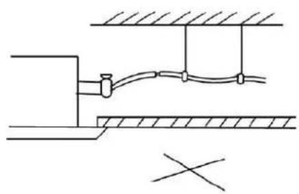
natural_image
Pure technical diagram of a mechanical or electrical assembly without any text, numbers, or symbols4.3. INSTALLARE IL CONTROLLO A FILO A PARETE
natural_image
Technical line drawing of a mechanical assembly with threaded and hexagonal components (no text or symbols)| DIAMETRO del TUBO | COPPIA |
| 6.35mm (1/4") | 15-19 N m |
| 9.52mm (3/8") | 35-40 N m |
| 12.7mm (1/2") | 50-60 N m |
| 15.88mm (5/8") | 62-76 N m |
| 19.05mm (3/4") | 98-120 N m |
5.2. PROVA DI TENUTA
natural_image
Exterior view of a modern office building (no signage)
natural_image
Front view of a white SAV air conditioner unit with ventilation grille and ventilation duct (no visible text or symbols)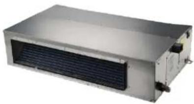
natural_image
Exterior view of a metallic industrial air conditioning unit with heat exchanger and cooling fins (no text or symbols visible)

natural_image
Exterior view of a BAXI air conditioner unit (no visible text or symbols on the device itself)
natural_image
Exterior view of a BAXI air conditioning unit with two circular fan blades (no text or symbols visible)| pt | Ar Condicionado bomba de calor DC inverter MONO Split. |
| Instruções de Instalação para INSTALADOR | |
| RZNK50, RZNK70, RZNK100, RZNK120, RZNK140, RZNK160, RZNC50, RZNC70, RZNC100, RZNC120, RZNC140, RZNC160, RZND50, RZND70, RZND100, RZND120, RZND140, RZND160 | |
| RZT50, RZT70, RZT100, RZT120, RZT140, RZT160 |
1. PRECAUÇÕES DE SEGURANÇA 4
1.1. ADVERTENCIAS....4
1.2. PRECAUÇÕES......4
1.3. ADVERTÊNCIA REEE 5
- ACESSÓRIOS INCLUIDOS....5
2.1. UNIDADE EXTERIOR 5
2.2. UNIDADE INTERIOR ....5
- DADOS TÉCNICOS....5
natural_image
Symbol of a trash bin crossed with diagonal lines, representing waste sorting or disposal (no text or labels)2. ACESSÓRIOS INCLUIDOS
2.1. UNIDADE EXTERIOR
natural_image
Technical line drawing of a three-tiered storage unit with dimension标注 (no text or symbols)
Instalação em teto
natural_image
Pure technical line drawing of a mechanical assembly without any text, numbers, or symbolsnatural_image
Technical line drawing of a mechanical component with threaded and flanged parts, showing internal structure (no text or symbols)| DIÂMETRO DO TUBO | TORQUE |
| 6.36mm (1/4") | 15-19 N m |
| 9.62mm (3/8") | 35-40 N m |
| 12.7mm (1/2") | 50-60 N m |
| 15.88mm (5/8") | 62-76 N m |
| 19.05mm (/") | 98-120 |
5.2. PROVA DE ESTANQUIDADE
natural_image
Exterior view of a modern recessed ceiling light fixture (no text or symbols visible)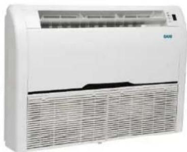
natural_image
Front view of a white industrial air conditioner unit with ventilation grille and ventilation duct (no visible text or symbols)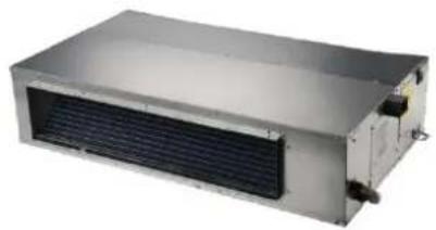
natural_image
Exterior view of a metallic industrial air conditioning unit with heat exchanger (no text or symbols visible)

natural_image
Front view of a vintage medical or laboratory device with control panels and display (no visible text or symbols)
natural_image
Exterior view of a BAXI air conditioner unit (no visible text or symbols on the device itself)
natural_image
Exterior view of a BAXI air conditioning unit with two circular fan blades (no text or symbols visible)natural_image
Symbolic illustration of a trash bin crossed out by diagonal lines, representing waste sorting or disposal (no text or labels)2. INKLUDIERTES ZUBEHÖR
natural_image
Technical line drawing of a rectangular enclosure with horizontal panels and a vertical dimension label (660 mm), no readable text or symbols present.
natural_image
Pure technical line drawing of a mechanical assembly without any text, numbers, or symbols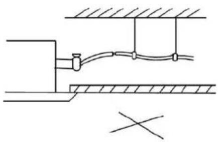
natural_image
Pure technical diagram of a pipe connection system without any text, numbers, or symbols4.3. INSTALLATION DER KABELFERNBEDIENUNG
natural_image
Technical line drawing of a mechanical component with threaded and flanged parts, showing directional arrow (no text or symbols)natural_image
Technical diagram of a mechanical joint or connector assembly (no text or symbols visible)
natural_image
Exterior view of a modern recessed ceiling light fixture with a grid-patterned ventilation grille (no text or symbols visible)
natural_image
Front view of a white industrial air conditioner unit with ventilation grille and fan (no visible text or symbols)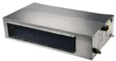
natural_image
Exterior view of a metallic industrial air conditioning unit with heat exchanger (no text or symbols visible)
natural_image
Front view of a vintage medical or laboratory device with control panels and display (no visible text or symbols)
natural_image
Exterior view of a BAXI air conditioner unit (no visible text or symbols on the device itself)
natural_image
Exterior view of a BAXI air conditioning unit with two circular fan blades (no text or symbols visible)| en | DC inverter air conditioner MONO Split with heat pump |
| Installation and Support Manual | |
| RZNK50, RZNK70, RZNK100, RZNK120, RZNK140, RZNK160, RZNC50, RZNC70, RZNC100, RZNC120, RZNC140, RZNC160, RZND50, RZND70, RZND100, RZND120, RZND140, RZND160 | |
| RZT50, RZT70, RZT100, RZT120, RZT140, RZT160 |
TABLE OF CONTENTS
1. SAFETY PRECAUTIONS....3
1.1. WARNINGS FOR INSTALLERS ....3
1.2.WEEE WARNINGS....5
2. ACCESSORIES INCLUDED....5
2.1. OUTDOOR UNITS....5
2.2. INDOOR UNITS....5
3. TECHNICAL DATA....5
3.1. OPERATION LIMITS....5
3.2. TECHNICAL CHARACTERISTICS 6
4. INSTALLATION....111
4.1. INSTALLING THE OUTDOOR UNIT....111
4.2. INSTALLING THE INDOOR UNIT....144
4.2.1.DUCT [RZND(50/70/100/120/140/160)]....144
4.2.2.CASSETTE [RZNK(50/70/100/120/140/160)]......166
4.2.3.FLOOR&CEILING [RZNC(50/70/100/120/140/160)]......20
4.3. INSTALLING THE WIRED CONTROL....211
5. REFRIGERANT PIPING....222
5.1. CONNECTING THE PIPING 222
5.2.LEAK TEST....233
5.3. CREATING THE VACUUM 233
5.4. REFRIGERANT GAS CHARGE....244
6. WIRING 255
6.1. POWER AND CONNECTION WIRING....255
6.2.WIRED CONTROL CONNECTION 266
The appliance can be used by children aged 8 or over and by people with reduced physical, sensory or mental faculties, or who do not have the required experience or knowledge, provided they are supervised or have received instructions on using the appliance safely and understanding its intrinsic hazards. Children must not play with the appliance. The cleaning and maintenance operations reserved to the user must not be performed by unsupervised children.
1. SAFETY PRECAUTIONS
1.1. WARNINGS FOR INSTALLERS
- The air conditioner may only be installed, plumbed in and wired by persons who meet the technical and professional requirements to install and maintain such systems.
- This air conditioner must be installed in accordance with national plant engineering regulations. Pay particular attention to the aspects concerning safety and the proper connection of electrical cables. Errors while connecting cables may lead to fires.
- Connect the air conditioner to the mains or to a power socket with a suitable voltage and frequency. A power supply with an incorrect voltage and frequency may result in damage to the unit with a consequent fire risk. The voltage must be stable and without excessive fluctuations.
- Install the condensation drainage piping so as to ensure that the condensation is removed correctly. Also adopt the most appropriate solutions to prevent heat loss and the resulting formation of condensation. An incorrect piping configuration may lead to water leakage and wet furniture and objects in the indoor environment. The air conditioner must be earthed. Incomplete or poorly set-up earth may cause electric shocks.
- Do not connect the earth cable to other pipes, water pipes, lightning rods or the telephone earth wire.
- Install an Omnipolar switch (with a minimum contact distance of at least 3 mm on all terminals on the power supply circuit to prevent possible discharge to ground and short circuits.
- The Omnipolar switch and any socket must be installed in an easily accessible location.
- Do not remove the power cable while the unit is running or with wet hands. Doing so risks electric shocks and fires.
- Use cables that are intact and whose cross-section is appropriate for the load for the power supply.
- Do not make joints on the power cable. Use a longer cable if necessary. Joints can cause overheating or fire.
- In the event that the power cable is damaged, it must be replaced. Use a type of cable featured in the manual only.
- Install a noise filter if the power supply emits too much noise.
- Do not leave any cables in direct contact with the refrigerant piping which could reach excessive temperatures.
- Do not leave any cables in direct contact with moving parts, such as fans. Make sure the communication cables between the units are connected to the correct terminals.
- Only replace fuses with ones identical to the original.
- If the filter is very dirty, this will significantly reduce the cooling capacity of the appliance.
- Tighten the nut to the torque indicated in the device manual. Overtightening can lead to leakage of refrigerant.
-
Do not install the indoor unit outside. Doing so may result in damage and electrical losses.
-
During installation of the indoor unit(s), consider the distribution of air in each indoor unit in the room in order to select the most suitable position and ensure a temperature as uniform as possible within the environment.
- Do not install the indoor unit in a location directly exposed to sunlight.
- Do not install the unit near liquids and highly flammable gases. Install the unit in locations with the minimum content of dust, smoke, air humidity and corrosive agents.
- Place the indoor unit at a distance of at least 1 meter from televisions, radios and general electrical equipment whose electromagnetic waves may directly influence the electrical box or remote control.
- Pay particular attention to the installation warnings and conditions of use if the indoor units are located in hospitals, near medical equipment or generally in places with significant electromagnetic waves.
- If the indoor units are installed in areas exposed to high concentrations of magnetic interference, you must use shielded twisted cables far communication links between units.
- Do not install in laundries.
- This type of indoor unit does not use an electric heater. You cannot install an electric heater or an electric stove at the installation site.
- Install the indoor unit on a solid surface that can support the weight of the air conditioner. Make sure that the support is securely installed and the unit is stable even after running for an extended period. If not properly secured, the unit may fall and cause damage or injury to objects and persons.
- Do not place objects of any kind inside the indoor unit. Remember to check that there are no foreign objects inside the unit before installation and testing.
- Far the outdoor unit, choose an installation location where the noise and the air jet do not disturb neighbors.
- Avoid placing the outdoor unit in a location where it causes an obstacle to pedestrians.
- Position the outdoor unit in line with local architectural rules.
- Respect the dimensions given in the manual, the lengths of the refrigerant lines and the height difference between units.
- Ensure that the appliances are not accessible by disabled persons and children. Do not block the entrances to the air inlets and outlets. Doing so will significantly reduce the heating and cooling capacity.
- Do not place objects on the outdoor unit or climb over it. Perform a test after carrying out wiring.
- Wiring diagrams are subject to ongoing updates. It is therefore compulsory to refer to those on the machine itself.
- Before turning on the air conditioner, make sure that the electrical cables, condensation drainage pipes and refrigerant connections are properly configured and installed. This eliminates the risk of water or refrigerant gas leaks or electric shocks.
- Periodically check the conditions of installation of the unit. Have the system checked by qualified personnel.
- After switching on the air conditioner, do not switch it off for at least 5 minutes. This prevents oil from returning to the compressor.
- Do not disassemble are repair the unit while it is running.
1.2. WEEE WARNINGS
- Do not dispose of electronic equipment as household waste. Use proper disposal facilities.
- Contact your local council for more information about the collection systems available.
- If electrical appliances are disposed of in landfills, hazardous substances can leak out, contaminate water and reach the food chain, affecting our health and wellbeing.
- When old appliances are replaced by new ones, the retailer is legally obliged to take back your old appliance far disposal free of charge.

natural_image
Simple line drawing of a trash bin with crossed lines indicating no waste or discharge (no text or symbols)2. ACCESSORIES INCLUDED
2.1. OUTDOOR UNITS
| QUANTITY | |||||||
| No. | NAME | RZT50 | RZT70 | RZT100 | RZT120 | RZT140 | RZT160 |
| 1 | Installer manual | 1 | 1 | 1 | 1 | 1 | 1 |
| 2 | Drainage connector | 1 | 1 | 1 | 1 | 1 | 1 |
| 3 | Copper nuts | 2 | 2 | 2 | 2 | 2 | 2 |
2.2. INDOOR UNITS
| QUANTITY | ||||
| No. | NAME | RZND | RZNK | RZNC |
| 1 | User manual | 1 | 1 | 1 |
| 2 | Remote Control | 0 | 1 | 1 |
| 3 | Batteries | 0 | 2 | 2 |
| 4 | Wired Control | 1 | 0 | 0 |
| 5 | Panel screws | 0 | 4 | 0 |
| 6 | Transfer tube | 0 | 1 | 1 |
| 7 | Thermal insulation | 2 | 2 | 2 |
N.B.
- All the descriptions and figures shown in this manual are approximate and may differ slightly from the actual appliance purchased and its conditions of use.
- If there are any differences, always refer to the latter conditions.
3. TECHNICAL DATA
*These Air Conditioners contain fluorinated greenhouse gases covered by Kyoto protocol.
Fan characteristics


line
| Available static pressure (Pa) | Turbo | High | Medium | Low | | ------------------------------ | ------ | ------ | ------ | ------ | | 0 | 1700 | 1500 | 1400 | 1200 | | 10 | 1650 | 1450 | 1350 | 1150 | | 20 | 1600 | 1400 | 1300 | 1100 | | 30 | 1550 | 1350 | 1250 | 1050 | | 40 | 1500 | 1300 | 1200 | 1000 | | 50 | 1450 | 1250 | 1150 | 950 | | 60 | 1400 | 1200 | 1100 | 850 | | 70 | 1350 | 1150 | 1050 | 750 | | 80 | 1300 | 1100 | 1000 | 700 |
line
| Available static pressure (Pa) | Turbo | High | Medium | Low | | ------------------------------ | ------ | ------ | ------ | ------ | | 0 | 2500 | 2400 | 2100 | 1800 | | 10 | 2300 | 2200 | 1950 | 1700 | | 20 | 2200 | 2100 | 1850 | 1650 | | 30 | 2100 | 1950 | 1750 | 1550 | | 40 | 2000 | 1800 | 1650 | 1450 | | 50 | 1900 | 1700 | 1550 | 1350 | | 60 | 1800 | 1600 | 1450 | 1250 | | 70 | 1700 | 1500 | 1350 | 1150 | | 80 | 1600 | 1400 | 1250 | 1050 |RZND120

line
| Available static pressure (Pa) | Turbo | High | Medium | Low | | ------------------------------ | ------ | ------ | ------ | ------ | | 0 | 2600 | 2300 | 2200 | 1950 | | 10 | 2450 | 2200 | 2150 | 1850 | | 20 | 2350 | 2150 | 2100 | 1750 | | 30 | 2250 | 2100 | 2050 | 1650 | | 40 | 2150 | 2050 | 2000 | 1550 | | 50 | 2050 | 2000 | 1950 | 1450 | | 60 | 1950 | 1950 | 1850 | 1350 | | 70 | 1850 | 1850 | 1750 | 1250 | | 80 | 1750 | 1750 | 1650 | 1150 |RZND(140/160)

line
| Available static pressure (Pa) | Turbo | High | Medium | Low | | ------------------------------ | ------ | ------ | ------ | ------ | | 0 | 2950 | 2700 | 2450 | 2200 | | 10 | 2950 | 2700 | 2450 | 2200 | | 20 | 2950 | 2700 | 2450 | 2200 | | 30 | 2950 | 2650 | 2350 | 2150 | | 40 | 2900 | 2600 | 2300 | 2100 | | 50 | 2850 | 2550 | 2250 | 2050 | | 60 | 2800 | 2500 | 2200 | 2000 | | 70 | 2750 | 2450 | 2150 | 1950 | | 80 | 2700 | 2400 | 2100 | 1900 |N.B.
- Turbo speed can be only selected with remote control. Not available for wired control.
| CASSETTE UNITS | ||||||
| Kits | RZK50 | RZK70 | RZK100 | RZK120 | RZK140 | RZK160 |
| Type | ULTRA DC Inverter | ULTRA DC Inverter | ULTRA DC Inverter | ULTRA DC Inverter | ULTRA DC Inverter | ULTRA DC Inverter |
| Cooling capacity nom.(min.-max.) (kW) | 5,00(1,53-5,60) | 7,00(2,16-8,20) | 10,5(2,9-12,0) | 12,1(3,2-13,2) | 14,00(4,10-16,00) | 16,00(4,80-17,30) |
| Heating capacity nom.(min.-max.) (kW) | 5,60(1,40-6,20) | 8,00(1,98-9,30) | 12,5(2,6-13,2) | 13,5(3,0-14,7) | 16,00(4,60-17,50) | 17,00(4,90-18,50) |
| SEER/SCOP | 6,1/4,0 | 6,1/4,0 | 6,1/4,0 | 5,6/4,0 | 5,6/4,0 | 5,6/4,0 |
| Energy rating cooling/heating | A++/A+ | A++/A+ | A++/A+ | A+/A+ | A+/A+ | A+/A+ |
| Power consumption cooling nom.(min.-max.) (kW) | 1,54(0,47-2,30) | 2,05(0,67-3,56) | 3,28(0,71-4,71) | 4,28(0,8-5,39) | 4,67(1,21-6,48) | 5,61(1,38-6,85) |
| Current consumption cooling nom.(min.-max.) (A) | 6,76(2,25-10,10) | 9,02(3,21-15,63) | 14,56(3,84-20,67) | 18,97(4,35-23,66) | 7,32(2,50-10,39) | 8,81(2,85-10,99) |
| Power consumption heating nom.(min.-max.) (kW) | 1,55(0,46-2,25) | 2,20(0,65-3,62) | 3,64(0,47-4,13) | 4,10(0,58-4,90) | 4,57(0,92-5,66) | 4,96(0,98-6,00) |
| Current consumption heating nom.(min.-max.) (A) | 6,81(2,20-9,88) | 9,65(3,11-15,90) | 16,17(2,57-18,3) | 18,19(3,14-21,74) | 7,17(1,90-9,08) | 7,78(2,02-9,62) |
| Max. power consumption (kW) | 2,40 | 3,80 | 5,37 | 5,68 | 7,00 | 7,50 |
| Max. current consumption (A) | 13,04 | 20,65 | 23,6 | 24,9 | 10,31 | 11,05 |
| Power supply (V~,Hz,Phases) | 220~240, 50,1 | 220~240, 50,1 | 220~240, 50,1 | 220~240, 50,1 | 380~415, 50,3 | 380~415, 50,3 |
| Liquid piping diameter (inch/mm) | 1/4"/6.35 | 3/8"/9.52 | 3/8"/9.52 | 3/8"/9.52 | 3/8"/9.52 | 3/8"/9.52 |
| Gas piping diameter (inch/mm) | 1/2"/12.7 | 5/8"/15.88 | 5/8"/15.88 | 5/8"/15.88 | 3/4"/19,05 | 3/4"/19,05 |
| Indoor unit | RZNK50 | RZNK70 | RZNK100 | RZNK120 | RZNK140 | RZNK160 |
| Body Commercial Name | RZBK50 | RZBK70 | RZBK100 | RZBK120 | RZBK140 | RZBK160 |
| Panel Commercial Name | PK50 | PK160 | PK160 | PK160 | PK160 | PK160 |
| Power supply wires (mm2) | 2x1,0+E | 2x1,0+E | 2x1,0+E | 2x1,0+E | 4x1,0+E | 4x1,0+E |
| Connection wires (mm2) | 2x0,2 | 2x0,2 | 2x0,2 | 2x0,2 | 2x0,2 | 2x0,2 |
| Body Dimensions width/depth/height (mm) | 570x570x260 | 835x835x250 | 835x835x290 | 835x835x290 | 835x835x290 | 835x835x290 |
| Panel Dimensions width/depth/height (mm) | 650x650x55 | 950x950x55 | 950x950x55 | 950x950x55 | 950x950x55 | 950x950x55 |
| Body Weight (kg) | 17 | 24 | 26,5 | 26,5 | 26,5 | 26,5 |
| Panel Weight (kg) | 3 | 5 | 5 | 5 | 5 | 5 |
| Air flow volume Hi/Me/Lo (m3/h) | 800/670/550 | 1300/1050/950 | 1800/1550/1350 | 1800/1550/1350 | 2050/1750/1500 | 2050/1750/1500 |
| Sound pressure Hi/Me/Lo dB(A) | 46/44/36 | 47/43/38 | 51/48/45 | 51/48/45 | 53/48/42 | 53/48/42 |
| Sound power dB(A) | 56 | 57 | 62 | 62 | 63 | 63 |
| Outdoor unit | RZT50 | RZT70 | RZT100 | RZT120 | RZT140 | RZT160 |
| Power supply wires (mm2) | 2x2,5+E | 2x4,0+E | 2x6,0+E | 2x6,0+E | 4x1,5+E | 4x1,5+E |
| Dimensions width/depth/height (mm) | 800x286x530 | 890x320x670 | 940x368x1366 | 940x368x1366 | 940x368x1366 | 940x368x1366 |
| Weight (kg) | 40 | 53 | 93 | 93 | 108 | 108 |
| Sound pressure dB(A) | 55 | 58 | 58 | 58 | 59 | 59 |
| Sound power dB(A) | 64 | 66 | 67 | 67 | 68 | 68 |
| Refrigerant type (GWP)* | R410A (2088) | |||||
| Refrigerant quantity (kg) | 1,28 | 1,90 | 2,85 | 2,85 | 3,70 | 3,70 |
| tCO2 eq. | 2,67 | 3,97 | 5,95 | 5,95 | 7,73 | 7,73 |
| Meters of precharge gas quantity (m) | 8 | 8 | 8 | 8 | 8 | 8 |
| Additional charge (g/m) | 20 | 50 | 50 | 50 | 50 | 50 |
| Max. discharge pressure (MPa) | 4,15 | 4,15 | 4,15 | 4,15 | 4,15 | 4,15 |
| Max. suction pressure (MPa) | 1,15 | 1,15 | 1,15 | 1,15 | 1,15 | 1,15 |
*These Air Conditioners contain fluorinated greenhouse gases covered by Kyoto protocol.
| FLOOR&CEILING UNITS | ||||||
| Kits | RZC50 | RZC70 | RZC100 | RZC120 | RZC140 | RZC160 |
| Type | ULTRA DC Inverter | ULTRA DC Inverter | ULTRA DC Inverter | ULTRA DC Inverter | ULTRA DC Inverter | ULTRA DC Inverter |
| Cooling capacity nom.(min.-max.) (kW) | 5,00(1,53-5,60) | 7,00(2,16-8,20) | 10,5(2,9-12,0) | 12,1(3,2-13,2) | 14,00(4,10-16,00) | 16,00(4,80-17,30) |
| Heating capacity nom.(min.-max.) (kW) | 5,60(1,40-6,20) | 8,00(1,98-9,30) | 12,5(2,6-13,2) | 13,5(3,0-14,7) | 16,00(4,60-17,50) | 17,00(4,90-18,50) |
| SEER/SCOP | 6,1/4,0 | 6,1/4,0 | 6,1/4,0 | 5,6/4,0 | 5,6/4,0 | 5,6/4,0 |
| Energy rating cooling/heating | A++/A+ | A++/A+ | A++/A+ | A+/A+ | A+/A+ | A+/A+ |
| Power consumption cooling nom.(min.-max.) (kW) | 1,54(0,47-2,30) | 2,05(0,67-3,56) | 3,37(0,71-4,71) | 4,28(0,8-5,39) | 4,95(1,21-6,48) | 5,80(1,38-6,85) |
| Current consumption cooling nom.(min.-max.) (A) | 6,76(2,25-10,10) | 9,02(3,21-15,63) | 14,93(3,84-20,67) | 18,97(4,35-23,66) | 7,76(2,50-10,39) | 9,10(2,85-10,99) |
| Power consumption heating nom.(min.-max.) (kW) | 1,55(0,46-2,25) | 2,20(0,65-3,62) | 3,68(0,47-4,13) | 4,10(0,58-4,90) | 4,57(0,92-5,66) | 4,96(0,98-6,00) |
| Current consumption heating nom.(min.-max.) (A) | 6,81(2,20-9,88) | 9,65(3,11-15,90) | 16,31(2,57-18,3) | 18,19(3,14-21,74) | 7,17(1,90-9,08) | 7,78(2,02-9,62) |
| Max. power consumption (kW) | 2,40 | 3,80 | 5,37 | 5,68 | 7,00 | 7,50 |
| Max. current consumption (A) | 13,04 | 20,65 | 23,6 | 24,9 | 10,31 | 11,05 |
| Power supply (V~,Hz,Phases) | 220~240, 50,1 | 220~240, 50,1 | 220~240, 50,1 | 220~240, 50,1 | 380~415, 50,3 | 380~415, 50,3 |
| Liquid piping diameter (inch/mm) | 1/4"/6.35 | 3/8"/9.52 | 3/8"/9.52 | 3/8"/9.52 | 3/8"/9.52 | 3/8"/9.52 |
| Gas piping diameter (inch/mm) | 1/2"/12.7 | 5/8"/15.88 | 5/8"/15.88 | 5/8"/15.88 | 3/4"/19,05 | 3/4"/19,05 |
| Indoor unit | RZNC50 | RZNC70 | RZNC100 | RZNC120 | RZNC140 | RZNC160 |
| Power supply wires (mm2) | 2x1,0+E | 2x1,0+E | 2x1,0+E | 2x1,0+E | 4x1,0+E | 4x1,0+E |
| Connection wires (mm2) | 2x0,2 | 2x0,2 | 2x0,2 | 2x0,2 | 2x0,2 | 2x0,2 |
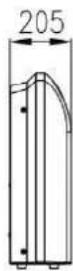
| Dimensions width/height/depth (mm) | 930×660×205 | 1280×660×205 | 1630×660×205 | 1630×660×205 | 1630×660×205 | 1630×660×205 |
| Weight (kg) | 25 | 32 | 44 | 44 | 44 | 44 |
| Air flow volume Hi/Me/Lo (m3/h) | 900/730/650 | 1300/1052/920 | 1800/1550/1350 | 1800/1550/1350 | 2000/1600/1400 | 2000/1600/1400 |
| Sound pressure Hi/Me/Lo dB(A) | 45/42/37 | 47/45/43 | 53/50/47 | 53/50/47 | 54/50/46 | 54/50/46 |
| Sound power dB(A) | 55 | 57 | 63 | 63 | 64 | 64 |
| Outdoor unit | RZT50 | RZT70 | RZT100 | RZT120 | RZT140 | RZT160 |
| Power supply wires (mm2) | 2x2,5+E | 2x4,0+E | 2x6,0+E | 2x6,0+E | 4x1,5+E | 4x1,5+E |
| Dimensions width/depth/height (mm) | 800×286×530 | 890×320×670 | 940×368×1366 | 940×368×1366 | 940×368×1366 | 940×368×1366 |
| Weight (kg) | 40 | 53 | 93 | 93 | 108 | 108 |
| Sound pressure dB(A) | 55 | 58 | 58 | 58 | 59 | 59 |
| Sound power dB(A) | 64 | 66 | 67 | 67 | 68 | 68 |
| Refrigerant type (GWP)* | R410A (2088) | |||||
| Refrigerant quantity (kg) | 1,28 | 1,90 | 2,85 | 2,85 | 3,70 | 3,70 |
| tCO2 eq. | 2,67 | 3,97 | 5,95 | 5,95 | 7,73 | 7,73 |
| Meters of precharge gas quantity (m) | 8 | 8 | 8 | 8 | 8 | 8 |
| Additional charge (g/m) | 20 | 50 | 50 | 50 | 50 | 50 |
| Max. discharge pressure (MPa) | 4,15 | 4,15 | 4,15 | 4,15 | 4,15 | 4,15 |
| Max. suction pressure (MPa) | 1,15 | 1,15 | 1,15 | 1,15 | 1,15 | 1,15 |
*These Air Conditioners contain fluorinated greenhouse gases covered by Kyoto protocol.
4. INSTALLATION
4.1. INSTALLING THE OUTDOOR UNIT
- Make sure that the outdoor unit is fastened securely.
- Install the unit in accordance with the information contained in the table below.
- If installing in marine environments or in locations that are very high in relation to the ground floor and/or in the presence of strong winds, use a locking plate and fit it against the wall so that the compressor can operate properly.
- If installing in a normal location, the structure of the support base must be made of concrete or material with equivalent strength and have necessary support ability. Alternatively, adopt by all the support measures needed to prevent the unit from vibrating.
- If you decide to protect the outdoor unit from rain and direct sunlight Kith a special canopy, be careful not to under heat radiation by the compressor.
- Do not grow plants or raise animals in the vicinity of the compressor because the heat could affect normal growth.
- Make sure there is a suitable distance from ceilings, walls, furniture and other obstacles.
- Secure the unit away from heat sources and/or flammable gases.
- The installation base and support frame must be adequate and secure. The machine must normally be installed on a flat surface.
Installation space
Please be sure to meet the following installation space requirements when selecting the installation site:
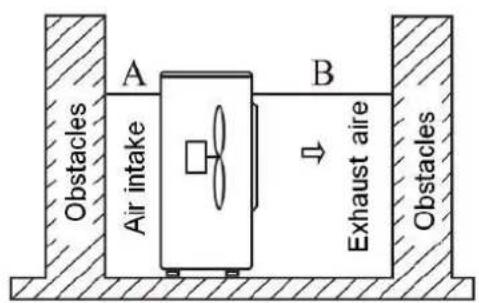


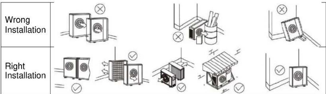
A>300mm ; B>1500mm ; C>300mm ; D>500mm
The following figures show the right and the wrong installations:
Location of the hosting bolt

| MODEL | A | B | C | D |
| RZT50 | 288 | 546 | 799 | 545 |
| RZT70 | 320 | 632 | 900 | 700 |
| RZT100 | 388 | 610 | 940 | 1366 |
| RZT120 | 388 | 610 | 940 | 1366 |
| RZT140 | 388 | 610 | 940 | 1366 |
| RZT160 | 388 | 610 | 940 | 1366 |
Connecting the piping
Wrap all the pipes, the drainage pipe and the electrical cables from the top to the bottom. Wrap the pipes with tape along the route and secure them to the wall Kith the special clips. These steps only concern cases where the outdoor unit is installed below the indoor one.

- If you want to add additional water drainage, keep at a certain distance from the ground and from the surface of the water. Do not immerse the pipe(s) in the water.
- Secure the pipe(s) to the wall so they are not affected by the Kind.
- Wrap the pipes and electrical cables well from bottom to top.
- Wrap the pipes and shape them, especially around corners to prevent water from infiltrating the home.
- Use clamps or other accessories to secure the pipes to the wall.
Length of refrigerant connections

Note: All the requirements below should be met at the same time:
| RZT50 | RZT70 | RZT100 | RZT120 | RZT140 | RZT160 | ||
| Maximum distance of connections (m) | L | 20 | 30 | 30 | 30 | 50 | 50 |
| Maximum height difference (m) | H | 15 | 15 | 15 | 15 | 30 | 30 |
| Max. distance with precharge (m) | P | 8 | 8 | 8 | 8 | 8 | 8 |
| Additional charge (g/m) | C | 20 | 50 | 50 | 50 | 50 | 50 |
Refrigerant adjustment: If total pipe length exceeds 8m, additional refrigerant (R410A) change is required. (The outdoor unit is charged with refrigerant for total pipe length up to 8m).
4.2. INSTALLING THE INDOOR UNIT
- Consider the distribution of air from the indoor unit to the home and select a suitable position in order to achieve a uniform air temperature in the place of installation.
- Make sure that there are no sources of heat and/or steam nearby.
- Maintain good air circulation.
- Consider adopting measures to reduce noise.
- Do not install the unit near doors and/or windows.
4.2.1. DUCT [RZND(50/70/100/120/140/160)]
Installation space
Please be sure to meet the following installation space requirements when selecting the installation site:
Location of the hosting bolt
| Model | A | B | C |
| 50 | 590 | 890 | 940 |
| 70 | |||
| 100 | 950 | 1250 | 1300 |
| 120 | |||
| 140 | |||
| 160 |
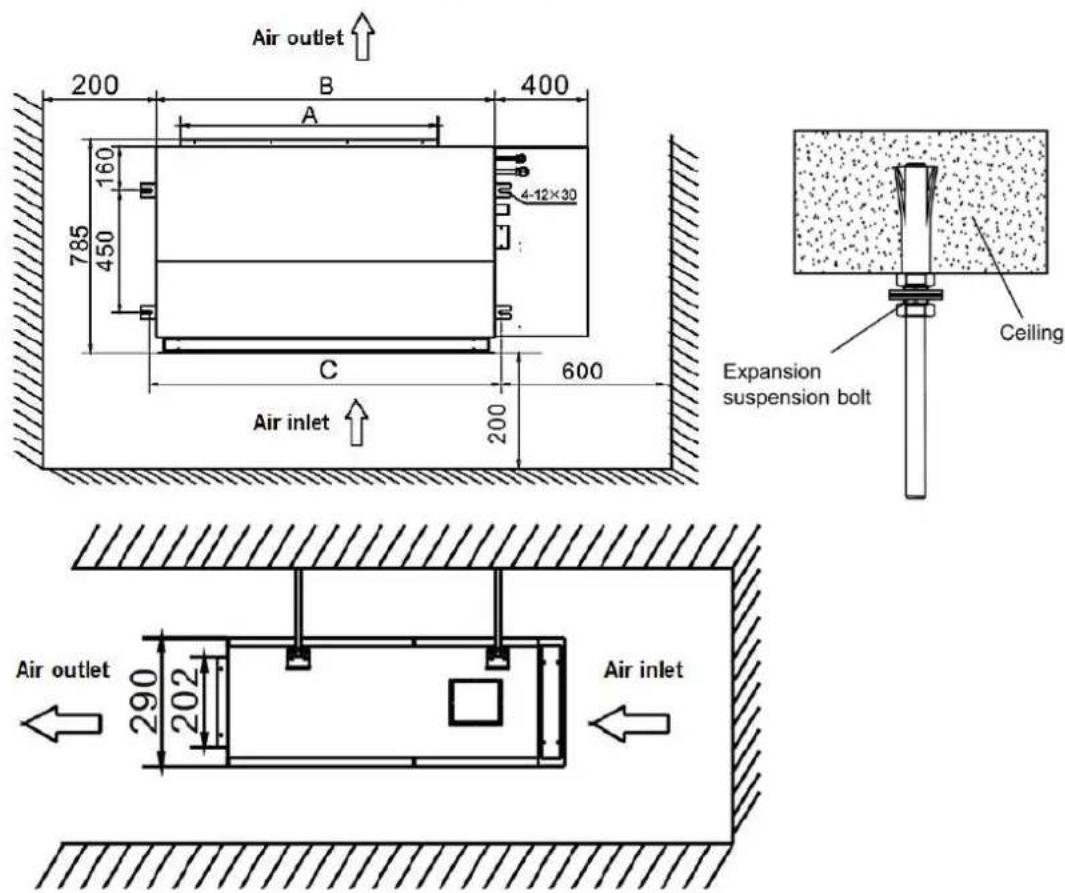
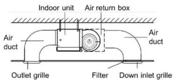
Duct installation
There are two installation methods of duct, as follows:

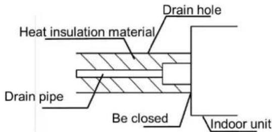
Drainage pipe installation
- A shown in the picture, the indoor unit should be leaning to the drain hole to be convenient for drainage.

- The drain pipe must have downward gradient (1/50-1/100). If the drain pipe is installed ups and downs or upward, it will lead to water backflow or leakage.
- During the pipe connection, do not use too much force to the drain joint of indoor unit.
- There is a drain hole on each side of the indoor unit; unused drain pipe must be closed.

- The unit has drain pump which will lift up to 1200 mm.
N.B
- The drain pipe must be wrapped heat insulation material (rubber insulation with thickness more than 8mm), otherwise it will cause condensation or water drops.

4.2.2. CASSETTE [RZNK(50/70/100/120/140/160)]
Installation space
Please be sure to meet the following installation space requirements when selecting the installation site:

The distance away from the ceiling and obstacles is shown in the below drawing:

| Ensure the installation position is able to take four times of the unit weigh There should be no increase in noise and vibration. |

Grille installation
The grille has four clips witch attach to corresponding hangers on the unit. The grille should be positioned using these first.
The grille is then fixed into positioning by four bolts which are accessed through the four corner panels on the grille.
The four connection bolts are located inside the inlet panel of the grille.
N.B
- During the installation please ensure that the air vane motor in the grille corresponds to the position of the refrigerant pipe entry into the indoor unit.
Location of the hosting bolt
Model 50
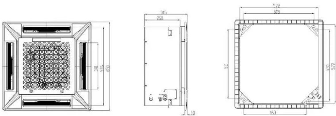
Model 70


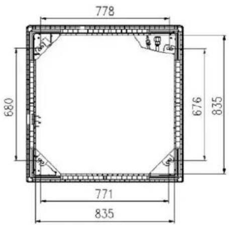
Model 100/120/140/160
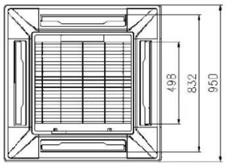


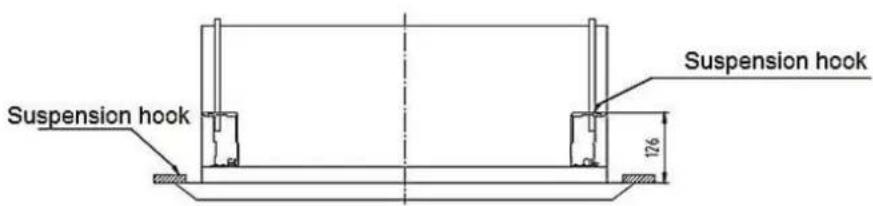
The suspension foundation must be firm and reliable to bear the weight of more than 200 kg and capable of bearing vibration for long periods.
The cassette should be suspended as shown in the below sketch:



Drainage pipe installation
- The drain pipe should be properly insulated to prevent the generation of condensation. It should be installed with a downward gradient (1/100-150).
2.
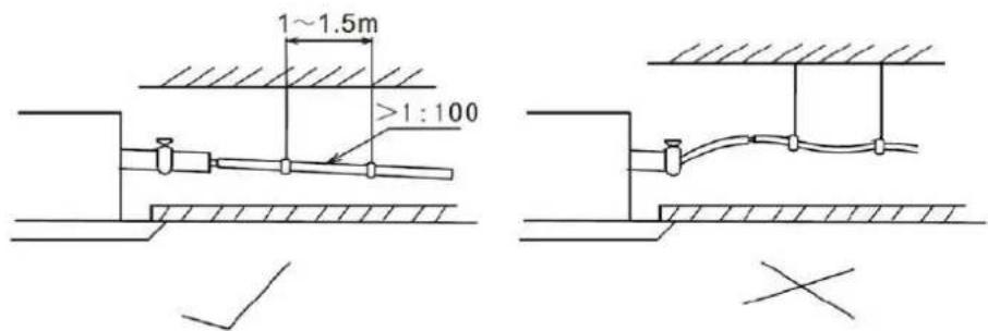
- The unit has drain pump which will lift up to 700 mm for model 50 and 1200 mm for models 70/100/120/140/160. However after the pump stops the water still in the pipe will drain back and may overflow the drain tray causing a water leak.
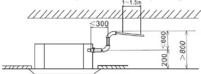
- When draining multiple units into a common drain line, tHs common drain should be installed about 100mm below each units drain outlet, as shown in the drawing.

4.2.3. FLOOR&CEILING [RZNC(50/70/100/120/140/160)]
Installation space
Please be sure to meet the following installation space requirements when selecting the installation site:
Ceiling installation

Floor installation

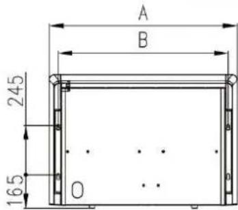
Location of the hosting bolt
| MODEL | A | B |
| 50 | 929 | 841 |
| 70 | 1280 | 1192 |
| 100 | 1631 | 1543 |
| 120 | ||
| 140 | ||
| 160 |

natural_image
Technical line drawing of a three-tiered storage unit with height dimension labeled (660 mm), no text or symbols present.
Ceiling installation
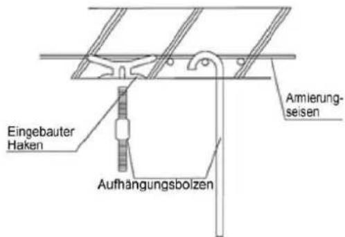
- The suspension foundation must be firm and reliable to bear the weight of more than 200 kg and capable of bearing vibration for long periods.
- The suspension of the indoor unit should carried out as described below:
a. Adjust the relative positions of the suspension hooks to ensure the indoor unit is level in all directions. Use a spirit level to ensure this, otherwise water leakage will happen.
b. Tighten the nuts and ensure that the hooks are tightly connected to the nuts.
c. After the unit is installed ensure it is secure and does not shake or sway.


natural_image
Pure technical line drawing of a mechanical assembly without any text, numbers, or symbolsDrainage pipe installation
- The drain pipe should be properly insulated to prevent the generation of condensation.
- Pipes should be installed with a downward gradient (1/100-150) to allow the water to drain away. The pipe should not rise at any point.


natural_image
Pure technical diagram of a pipe connection with no text, numbers, or symbols
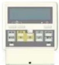
4.3. INSTALLING THE WIRED CONTROL
- Disconnect the Base panel from the wired controller.
- Use two screws to fix the base panel to the wall as shown below.
- Ensure that the connecting cable of the controller is accessible before connecting the wired controller to the base panel.
- Join the wired controller connection cable to the indoor unit using the cable provided.

5. REFRIGERANT PIPING
5.1. CONNECTING THE PIPING
- The method for connecting the piping is the same for both units, indoor and outdoor.
- Connect the pipes to the unit. Tighten until the connection becomes firm and secure. Follow the directions shown in the figure.

natural_image
Technical line drawing of a mechanical assembly with threaded and bolted components (no text or symbols)Refer the direction to the picture

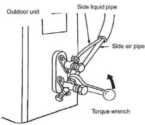
- Focusing on the center of the pipe, tighten the screw firmly.
- Tighten the conical nuts as shown in the figure by applying the corresponding torque according to the diameter of the pipe.
| PIPE DIAMETER | TORQUE |
| 6.35mm (1/4") | 15-19 N m |
| 9.52mm (3/8") | 35-40 N m |
| 12.7mm (1/2") | 50-60 N m |
| 15.88mm (5/8") | 62-76 N m |
| 19.05mm (3/4") | 98-120 N m |
5.2. LEAK TEST
Once all the refrigerant pipes have been connected, perform a test by pressurizing the system Kith nitrogen to make sure there are no leaks.
METHOD
- Connect the pressure gauge unit to the service valve on the outdoor unit gas pipe.
- Kith the outdoor unit service valves closed, connect the nitrogen cylinder to the pressure gauge unit so as to charge the pipes.
- Charge the installation (pipes and indoor unit) Kith nitrogen at a pressure of about 40 bars.
- Close the pressure gauge unit valves of the cylinder side. Then wait for the pressure to stabilize.
- Make sure that the pressure does not decrease. Once the pressure has stabilized, the test time can be about 30 minutes.
- After checking that the system is not leaking (using special leak detection devices), close the valve on the pressure gauge unit to remove the nitrogen cylinder.
5.3. CREATING THE VACUUM
After connecting the pipes and checking that there are no leaks, it is very important to create a vacuum in the system to eliminate the moist air from inside it. Failure to do so could cause problems to the compressor.
METHOD
- The air conditioner gas evacuated using a vacuum pump.
Connect the pipes of indoor units and outdoor unit according to the figure below, and tighten all the bell coupling nuts of indoor and outdoor to prevent leakage. - Connect the cut-off valves, charge hose, manifold valve, vacuum pump as the figure below.
- Please fully open the manifold valve handle Lo and H, and do the vacuum processing, vacuum should be running more than 15 minutes, make sure the vacuum gauge indicates the pressure has reached -0.1MPa (-76cmHg);
- After completion of vacuum processing, use the hex wrench to open a little the liquid valve of unit A, B and unit C, and then quickly remove the hose of gas valve (remove the hose to prevent air from entering the system);
- Open all the cut-off valve and check the connecting mouth of indoor and outdoor, then cover the cut-off valves after confirm there is no leak.

5.4. REFRIGERANT GAS CHARGE
If you need to install a length of pipe longer than standard (the length for which the unit is pre-charged), you must add the appropriate refrigerant charge.
| RZT50 | RZT70 | RZT100 | RZT120 | RZT140 | RZT160 | |
| ADDITIONAL CHARGE (g/m) | 20 | 50 | 50 | 50 | 50 | 50 |
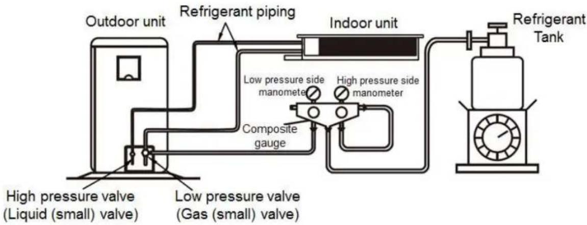
flowchart
graph LR
    A["Outdoor unit"] --> B["Refrigerant piping"]
    B --> C["Indoor unit"]
    C --> D["Refrigerant Tank"]
    E["High pressure valve (Liquid small) valve"] --> F["Low pressure valve (Gas small) valve"]
    G["Composite gauge"] --> H["Low pressure side manometer"]
    H --> I["High pressure side manometer"]
    I --> J["Indoor unit"]
METHOD
- Calculate the refrigerant charge to be added considering the parameters specified in the "LENGTH OF REFRIGERANT CONNECTIONS" section in tHs manual.
- Connect the R410A refrigerant cylinder in a position where the liquid can be Charged into the pressure gauge unit valve where the nitrogen cylinder or the vacuum pump has been connected.
- Connect the pressure gauge unit to the outdoor unit charging valve (gas). when injecting the liquid refrigerant through the gas valve, you must act slowly and pay attention so as to prevent liquid hammer to the compressor.
- Place the refrigerant cylinder on an electronic scale.
- Open the valve to allow the refrigerant to pass through.
- Close the valve when the weight of the cylinder coincides with the amount to be charged.
6. WIRING
6.1. POWER AND CONNECTION WIRING
The connection cables must comply with the specifications listed in the table below.
| WIRING SIZE | 50 | 70 | 100 | 120 | 140 | 160 |
| Indoor power supply wires (mm ^2 ) | 2x1,0+E | 2x1,0+E | 2x1,0+E | 2x1,0+E | 4x1,0+E | 4x1,0+E |
| Outdoor power supply wires (mm ^2 ) | 2x2,5+E | 2x4,0+E | 2x6,0+E | 2x6,0+E | 4x1,5+E | 4x1,5+E |
| Connection wires (mm ^2 ) | 2x0,2+E | 2x0,2+E | 2x0,2+E | 2x0,2+E | 2x0,2+E | 2x0,2+E |
Connect the power supply to the outdoor unit and conduct the wring connection as shown on the below diagram:
Model 50/70/100/120 (single-phase)

Model 140/160 (three-phase)
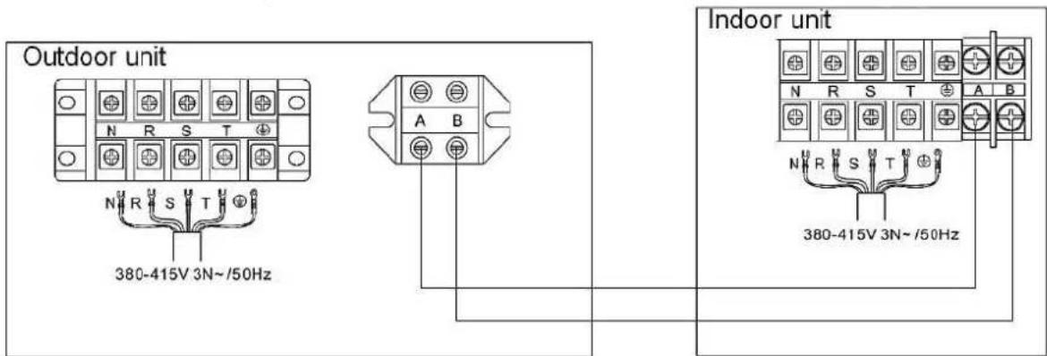
N.B.
- The connection wire of indoor units should be connected to the corresponding terminal board; otherwise it will cause the unit failure or even damage the units.
- Connect the grounded wire correctly, otherwise will cause the malfunction of some electrical component and shock or fire indeed.
- Don't reverse the power polarity.
- Must fix the screw nail of the firmly wire, then drag the wire lightly, confirmation whether it's firmly.
6.2. WIRED CONTROL CONNECTION
- In case of duct units, wired control is supplied as standard.
- Connect the white control connector to the "CN7" connector of the indoor unit PCB as shown in the following schema:

flowchart
graph TD
    subgraph Top_Motor_Control
        A["AC_N"] --> B["XE"]
        B --> C["CN1"]
        C --> D["CN3"]
        D --> E["CN9 UP_DW"]
        E --> F["CN7 CN16 CN15"]
        F --> G["Wired Control"]
        H["AC_L"] --> I["L_R"]
        I --> J["CN14"]
        J --> K["CN8"]
        K --> L["CN17"]
        L --> M["CN12 CN13"]
        M --> N["CN11"]
        N --> O["CN6"]
        O --> P["SW1 SW2"]
        P --> Q["CN10"]
        Q --> R["Display"]
        S["RD BU"] --> T["L N A B"]
        U["Power"] --> V["Communication"]
        W["Fan Motor"] --> X["Power PCB"]
        Y["Power"] --> Z["Communication"]
    end
    subgraph Bottom_Motor_Control
        AA["CN2"] --> AB["DFAN POWER PCB"]
        AC["DN3"] --> AD["M1 Fan Motor"]
    end
    style Top_Motor_Control fill:#f9f,stroke:#333
    style Bottom_Motor_Control fill:#ccf,stroke:#333
7. OPERATION TEST
7.1. TEST PROCEDURES
- Make sure that both the liquid and gas valves are fully open. Make sure there are no refrigerant leaks.
- Make sure that the electrical wiring of the indoor and outdoor units is connected as shown in "WIRING".
- Make sure that each terminal L, N is correctly connected to the mains.
- Turn on the air conditioner in cooling mode for 30 minutes or more.
7.2. EVALUATING PERFORMANCE
MODEL:
SERIAL NUMBER:
CUSTOMER NAME AND ADDRESS:
DATE:
- Is the direction of rotation of the indoor unit fan correct?
- Is the direction of rotation of the outdoor unit fan correct?
- Can you hear any abnormal compressor noises?
- Has the unit continued to run for at least 30 minutes?
- Checking the temperature in the room: In: BS____/BU____ °C
- Checking the outdoor temperature: Out: BS_/BU °C
- Checking the pressure: Discharge pressure: Ps=____ Bar Intake pressure: Pa=____ Bar
- Checking the voltage: Rated voltage: _V
- Check the current reaching the compressor Power consumption: __kW Current consumption: __A
- Is the refrigerant charge sufficient?
- Are the devices for controlling operation working correctly?
- Are the safety devices working correctly?
- Has the unit been checked for refrigerant leaks?
- Is the unit is clean both inside and outside?
- Is all the equipment secured?
- Is the equipment secured so that it does not make any noise?
- Is the filter clean?
- Is the heat exchanger clean?
- Are the gas and liquid service valves open?
- Does the waste water drain away without any problems?
8. ERROR CODES
The possible error codes that may appear on the display of the indoor unit or in the wired control are as follows:
8.1. INDOOR UNIT ERROR CODE EXPLANATION
| ERROR CODES | DESCRIPTION | RECOVERY OR NOT | PROBLEM POSSIBLE REASONS |
| A1 | Indoor ambient temperature sensor failure | YES | Indoor PCB is broken |
| The fuse of indoor PCB is borken | |||
| Temperature sensor is broken, or exceed test limit | |||
| A2 | Temperature sensor about middle position of evaporator failure | YES | Indoor PCB is broken |
| The fuse of indoor PCB is broken | |||
| Temperature sensor is broken, or exceed test limit | |||
| A5 | Indoor water pump failure | YES | Water pump no power |
| Water pump switch short-circuit or unconnected | |||
| Water pump is broken | |||
| Drain pipe block | |||
| Indoor PCB is broken | |||
| A6 | Indoor DC fan failure or broken | YES | DC fan motor drive module failure |
| DC fan failure | |||
| A8 | Indoor unit EPROM module failure | NO | Indoor unit PCB is broken |
| Error module is broken | |||
| A9 | The communication between indoor unit and outdoor unit failed | NO | The communication wire between indoor unit and outdoor unit is broken |
| Indoor unit power close or PCB is broken | |||
| AA | The communication between indoor unit and wire controller failed | NO | The communication wire between indoor unit and outdoor unit is broken |
| Indoor unit power close or PCB is broken | |||
| Wire controller is broken |
8.2. OUTDOOR UNIT ERROR CODE EXPLANATION
| ERROR CODES | DESCRIPTION | RECOVERY OR NOT | PROBLEM POSSIBLE REASONS |
| C1 | Ambient temperature sensor "Tao" failure | YES | Temperature sensor failure or test temperature exceed limit |
| Sensor connection is incorrect | |||
| Outdoor unit PCB failure | |||
| C2 | Defrosting temperature sensor "Tdef" failure | YES | Temperature sensor failure or test temperature exceed limit |
| Sensor connection is incorrect | |||
| Outdoor unit PCB failure | |||
| C3 | Discharge temperature of inverter compressor "Td" failure | YES | Temperature sensor failure or test temperature exceed limit |
| Sensor connection is incorrect | |||
| Outdoor unit PCB failure | |||
| C6 | Suction pipe temperature of compressor "Ts" failure | YES | Temperature sensor failure or test temperature exceed limit |
| Sensor connection is incorrect | |||
| Outdoor unit PCB failure | |||
| C8 | Coil Center temperature sensor "Tcm" failure | YES | Temperature sensor failure or test temperature exceed limit |
| Sensor connection is incorrect | |||
| Outdoor unit PCB failure | |||
| H1 | DC inverter compressor high pressure switch "HPS" failure | YES | System pressure exceed high pressure switch limit |
| High pressure switch failure | |||
| Instantaneous power-off | |||
| Stop valve closed | |||
| Outdoor unit fan stop or air outlet block | |||
| In heating mode indoor unit fan stop or EXV block | |||
| H4 | Low pressure switch “LPS” failure | YES | System pressure lower than low pressure switch limit |
| Low pressure switch failure | |||
| Instantaneous power-off | |||
| Stop valve closed | |||
| In cooling mode indoor unit EXV close or block | |||
| In heating mode outdoor unit EXV close or block | |||
| In heating mode outdoor unit fan stop | |||
| In heating mode outdoor unit air outlet block | |||
| E1 | 4 way valve protection | YES | 4 way valve block |
| Outdoor unit PCB failure | |||
| E3 | DC inverter discharge temperature “Td” too high shutdown protection | NO | System less refrigerant |
| DC inverter compressor failure | |||
| Compressor air return filtre block | |||
| EXV open degree is small or EXV block | |||
| Gas pipe stop valve closed | |||
| Liquid pipe stop valve closed | |||
| System exhaust sensor failure | |||
| Outdoor unit PCB failure | |||
| E8 | Coil Center temperature sensor “Tcm” too high shutdown protection | YES | System over refrigerant |
| EXV open degree is small or EXV block | |||
| System exhaust sensor failure | |||
| Outdoor unit PCB failure | |||
| J2 | The communication between outdoor unit and indoor unit failure | YES | The communication wire between indoor and outdoor units disconnected, short circuit or Connected incorrectly |
| Indoor unit power main PCB failure | |||
| J3 | The communication between PCB and INV module failure | YES | The connection between driving module and main PCB failure |
| The communication part of outdoor unit control PCB failure | |||
| Frequency driving board failure | |||
| Compressor failure | |||
| 3H/5H | The communication between main PCB and DC fan motor drive module failure | YES | DC fan operation failure |
| J7 | Outdoor unit main control PCB EPROM module failure | NO | Main PCB failure |
| 31 | Module protection (F0) | YES | Supply voltage below level let the current excessive |
| Supply voltage exceed limit | |||
| Outdoor fan stop or low speed | |||
| 32 | Module hardware protection | YES | Supply voltage below level let the current excessive |
| Supply voltage exceed limit | |||
| Outdoor fan stop or low speed | |||
| 33 | Module software protection | YES | Supply voltage below level let the current excessive |
| Supply voltage exceed limit | |||
| Outdoor fan stop or low speed | |||
| 34 | Compressor unconnected | YES | The connect of driving module and DC inverter compressor incorrect |
| Driving module failure | |||
| Compressor failure | |||
| 35 | Compressor phase current overload protection | YES | Compressor overload |
| Compressor coil disconnect | |||
| Inverter driving board failure | |||
| Compressor failure | |||
| 36 | DC bus voltage over-voltage or under-voltage failure | YES | Supply voltage below level |
| Supply voltage exceed limit | |||
| Driving board failure | |||
| 37 | Temperature sensor of drive module heat fins failure | YES | Inverter driving board failure |
| 38 | Drive module high temperature limit frequency failure | YES | Driving module failure |
| Compressor failure | |||
| Outdoor unit fan stop or low speed | |||
| 39 | Drive module high temperature shutdown protection | YES | Driving module failure |
| Compressor failure | |||
| Temperature sensor failure | |||
| 3E | DC inverter compressor running out of step | NO | Once confined the unrecoverable |
Our company declares that these products feature the CE marking in accordance with the essential requirements of the following directives:
- 2006/95/EC - Low Voltage Directive
- 2004/108/EC - Electromagnetic Compatibility Directive
- 2009/125/EC - ErP Directive

BAXI

- TABLA DE CONTENIDOS
- PRECAUCIONES DE SEGURIDAD....3
- ACCESORIO INCLUIDOS......4
- DATOS TÉCNICOS ....4
- ACCESORIO INCLUIDOS
- UNIDAD EXTERIOR
- INSTALACION DEL CONTROL POR CABLE
- SOMMARIO
- ACCESSORI INCLUSI....8
- DATI TECNICI....9
- INSTALLAZIONE 16
- TUBAZIONE DEL GAS REFRIGERANTE....27
- COLLEGAMENTI ELETTRICI ....30
- ACCESSORI INCLUSI
- UNITA' ESTERNA
- UNITA' INTERNA
- INSTALLARE IL CONTROLLO A FILO A PARETE
- PROVA DI TENUTA
- PRECAUÇÕES DE SEGURANÇA 4
- ACESSÓRIOS INCLUIDOS
- UNIDADE EXTERIOR
- Instalação em teto
- PROVA DE ESTANQUIDADE
- INKLUDIERTES ZUBEHÖR
- INSTALLATION DER KABELFERNBEDIENUNG
- TABLE OF CONTENTS
- SAFETY PRECAUTIONS....3
- ACCESSORIES INCLUDED....5
- TECHNICAL DATA....5
- INSTALLATION....111
- REFRIGERANT PIPING....222
- WIRING 255
- SAFETY PRECAUTIONS
- WARNINGS FOR INSTALLERS
- WEEE WARNINGS
- ACCESSORIES INCLUDED
- OUTDOOR UNITS
- INDOOR UNITS
- N.B.
- TECHNICAL DATA
- INSTALLATION
- INSTALLING THE OUTDOOR UNIT
- Installation space
- Location of the hosting bolt
- Connecting the piping
- INSTALLING THE INDOOR UNIT
- DUCT [RZND(50/70/100/120/140/160)]
- Duct installation
- Drainage pipe installation
- N.B
- CASSETTE [RZNK(50/70/100/120/140/160)]
- Grille installation
- FLOOR&CEILING [RZNC(50/70/100/120/140/160)]
- Ceiling installation
- INSTALLING THE WIRED CONTROL
- REFRIGERANT PIPING
- CONNECTING THE PIPING
- LEAK TEST
- METHOD
- CREATING THE VACUUM
- REFRIGERANT GAS CHARGE
- WIRING
- POWER AND CONNECTION WIRING
- WIRED CONTROL CONNECTION
- OPERATION TEST
- TEST PROCEDURES
- EVALUATING PERFORMANCE
- ERROR CODES
- INDOOR UNIT ERROR CODE EXPLANATION
- OUTDOOR UNIT ERROR CODE EXPLANATION
Brand : Baxi
Model : RZK140
Category : Air Conditioning