
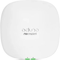
Aruba AP-565 - Access Point HP - Free user manual and instructions
Find the device manual for free Aruba AP-565 HP in PDF.


| Product Type | Wireless Access Point |
| Brand | HP (Aruba) |
| Model | Aruba AP-565 |
| Dimensions (W x D x H) | 200 mm x 200 mm x 45 mm |
| Weight | 1.0 kg |
| Power Supply | PoE (Power over Ethernet) or optional AC adapter |
| Wireless Standard | IEEE 802.11ax (Wi-Fi 6) |
| Frequency Bands | 2.4 GHz and 5 GHz |
| Maximum Data Rate | Up to 2.4 Gbps |
| Antenna Type | Internal dual-band antennas |
| MIMO | 4x4:4 on both bands |
| Ethernet Ports | 1 x 100/1000/2500Base-T (RJ-45) |
| Management | Aruba Central, Aruba Mobility Controllers, or local web UI |
| Security | WPA3, AES encryption, rogue AP detection |
| Mounting | Ceiling or wall mount (bracket included) |
| Operating Temperature | 0°C to 40°C |
| Humidity | 5% to 95% (non-condensing) |
| LED Indicators | Power, Ethernet, WLAN status |
| Maintenance | Clean with dry cloth; no user-serviceable parts |
| Spare Parts / Repairability | No user-replaceable parts; contact HP support for repairs |
| Compliance | FCC, CE, RoHS |
Frequently Asked Questions - Aruba AP-565 HP
User questions about Aruba AP-565 HP
0 question about this device. Answer the ones you know or ask your own.
Ask a new question about this device
Download the instructions for your Access Point in PDF format for free! Find your manual Aruba AP-565 - HP and take your electronic device back in hand. On this page are published all the documents necessary for the use of your device. Aruba AP-565 by HP.
USER MANUAL Aruba AP-565 HP
The Aruba 560 Series outdoor wireless access points (AP-565 and AP-567) are high-performance, multi-radio wireless devices that can be deployed in either controller-based (ArubaOS) or controllerless (Aruba Instant) network environment.
The Aruba 560 Series access points support IEEE 802.11ax standard, delivering high performance with the MIMO (Multiple-Input, Multiple-Output) technology, while also supporting 802.11a/b/g/n/ac wireless services.
Package Contents
• 560 Series access point - Cable gland x 1 • USB Type-C console cable x 1 • Grounding lug and M4x6 screw x 1
Tools Required
• Phillips screwdriver (#2 for M4x6 screw) - Flat blade screwdriver (Ethernet cable gland cover) - 8mm allen or hex key (USB console cover)

The weatherproof caps for Ethernet and Console interfaces are connected to the access point, not loose in the package.

Mounting kits for use with the 560 Series access points are sold separately. Contact your Aruba sales representative for details.

Inform your supplier if there are any incorrect, missing, or damaged parts. If possible, retain the carton, including the original packing materials. Use these materials to repack and return the unit to the supplier if needed.
Hardware Overview
Figure 1 560 Series Access Point
LED
The 560 Series access point is equipped with one LED that indicates the system status of the access point.
Table 1 560 Series LED Meanings during Boot Up
| LED Color/State Meaning | |
| System LED Off No power to AP | |
| Red Initial power-up | |
| Green - Flashing AP booting, not ready | |
| Green - Steady AP ready and Gigabit Ethernet connected. The LED turns off after 1200 seconds | |
| Green - Yellow, 6 seconds period | AP ready and 10/100Mbps Ethernet link established. The LED turns off after 1200 seconds |
Table 2 560 Series LED Meanings during Operation
| LED Color/State Meaning | ||
| System LED Solid Red General fault - Immediate attention required | ||
| One blink off every 3 seconds | Radio 0 fault (5 GHz) | |
| Two quick blink off 0.5 seconds apart cycled every 3 seconds | Radio 1 fault (2.4GHz) | |
Ethernet Port
The 560 Series access point is equipped with one Ethernet port (E0). The Ethernet port is 100/1000Base-T autosensing MDI/MDX, which supports uplink connectivity when linked by an Ethernet cable.
Power
The Ethernet port supports PoE-in, allowing the AP to draw power from an 802.3af/802.3at PoE power source. The 560 Series access point supports the Intelligent Power Monitoring (IPM) feature that actively measures the power utilization of the AP and dynamically adapts to the power budget.
Table 3 lists operational restrictions when the AP is powered by different power options.
Table 3 Power Options and Operational Restriction
| Power Source IPM Restrictions | ||
| 802.3at PoE n/a No restrictions, all capabilities available. | ||
| 802.3af PoE enabled AP starts up in unrestricted mode, but may dynamically apply restrictions depending on the PoE budget and actual power. | ||
| 802.3af PoE disabled 2.4GHz radio is restricted to 1 spatial stream. | ||
Grounding Point
Always remember to protect the access point by installing grounding lines. The ground connection must be complete before connecting power to the access point enclosure.
USB Type-C Console Port
Use the included USB Type-C console cable to connect the access point to a laptop or a serial terminal for direct management.

You need a proper 8mm allen or hex key to open the cover of the USB Console port.
Reset Button
The reset button can be used to reset the access point to factory default settings or turn off/on the LED display.
There are two ways to reset the access point to factory default settings:
Reset the AP during normal operation
Press and hold down the reset button using a small, narrow object such as a paper clip for more than 10 seconds during normal operation.
Reset the AP while powering up
- Press and hold down the reset button using a small, narrow object such as a paper clip while the access point is not powered on via PoE.
- Connect the power supply (PoE) to the access point while the reset button is being held down.
- Release the reset button on the access point after 15 seconds.
To turn off/on the LED display, press and release the reset button using a small, narrow object, such as a paperclip for less than 10 seconds during normal operation of the access point.
Before You Begin
Refer to the sections below before beginning the installation process.

FCC Statement: Improper termination of access points installed in the United States configured to non-US model controllers will be in violation of the FCC grant of equipment authorization. Any such willful or intentional violation may result in a requirement by the FCC for immediate termination of operation and may be subject to forfeiture (47 CFR 1.80).
Pre-Installation Checklist
Before installing your access point, be sure that you have the following:
- Cat5E or better UTP cable with network access • A compatible PoE injector with power cord One of the following network services: • Aruba Discovery Protocol (ADP) • DNS server with an "A" record • DHCP Server with vendor specific options

Aruba, in compliance with governmental requirements, has designed the 560 Series access points so that only authorized network administrators can change configuration settings. For more information about AP configuration, refer to the AP Software Quick Start Guide.

Access points are radio transmission devices and as such are subject to governmental regulation. Network administrators responsible for the configuration and operation of access points must comply with local broadcast regulations. Specifically, access points must use channel assignments appropriate to the location in which the access point will be used.
Outdoor Planning and Deployment Considerations
Prior to deploying an outdoor wireless network, the environment must be evaluated to plan for a successful WLAN deployment. Successfully evaluating the environment enables the proper selection of routers and antennas and assists in the determination of their placement for optimal RF coverage. This process is considered WLAN or RF planning and Aruba's system engineers can assist in the outdoor planning process.

The rules for the 5600-5650 MHz band vary by region.
Identifying Specific Installation Locations
Use the access point placement map generated by Aruba RF Plan software application to determine the proper installation location(s). Each location should be as close as possible to the center of the intended coverage area and should be free from obstructions or obvious sources of interference. These RF absorbers/reflectors/interference sources will impact RF propagation and should be accounted for during the planning phase and
Use of this equipment adjacent to or stacked with other equipment should be avoided because it could result in improper operation. If such use is necessary, this equipment and the other equipment should be observed to verify that they are operating normally.
Identifying Known RF Absorbers/Reflectors/Interference Sources
Identifying known RF absorbers, reflectors, and interference sources while in the field during the installation phase is critical. Make sure that these sources are taken into consideration when you attach an access point to its fixed location.
RF absorbers include:
- Cement/concrete—Old concrete has high levels of water dissipation, which dries out the concrete, allowing for potential RF propagation. New concrete has high levels of water concentration in the concrete, blocking RF signals. • Natural Items—Fish tanks, water fountains, ponds, and trees
- Brick
RF reflectors include:
- Metal Objects—Metal pans between floors, rebar, fire doors, air conditioning/heating ducts, mesh windows, blinds, chain link fences (depending on aperture size), refrigerators, racks, shelves, and filing cabinets.
- Do not place an access point between two air conditioning/heating ducts. Make sure that access points are placed below ducts to avoid RF disturbances.
RF interference sources include:
- Microwave ovens and other 2.4 or 5 GHz objects (such as cordless phones)
- Cordless headset such as those used in call centers or lunch rooms
Access Point Installation

Service to all Aruba products should be performed by trained service personnel only.
Using Mount Kits
The 560 Series access point can be installed on a wall or attached to a pole by using mount kits:
| Part Number Description |
| JW052A AP-270-MNT-V1 long mount kit for wall and vertical pole mounting, 300 mm from vertical mounting asset. |
| JW053A AP-270-MNT-V2 short mount kit for wall and vertical pole mounting, 75 mm from vertical mounting asset. |
| JW054A AP-270-MNT-H1 mount kit for hanging from inclined or horizontal structure. |
| JW055A AP-270-MNT-H2 flush mount kit for wall and ceiling mounting. |

The 560 Series access point does not ship with any mount kits. These mount kits are available as accessories and must be ordered separately.

For installation instructions on AP-270-MNT-V1, AP-270-MNT-V2, AP-270-MNT-H1 and AP-270-MNT-H2 mount kit, please refer to the AP-270-MNT-V1 Installation Guide, AP-270-MNT-V2 Installation Guide, AP-270-MNT-H1 Installation Guide and AP-270-MNT-H2 Installation Guide respectively.
This 560 Series access point is intended for installation in a RESTRICTED ACCESS LOCATION attached to a pole or installed on a wall. Installers should disconnect power before working with or near the access point.
Grounding the Access Point
The grounding must be completed before powering up the access point. The grounding wire should be #8 AWG.
- Peel the cover of one end of the grounding wire and place the bare grounding wire into the grounding lug (included in the package), and press firmly with the crimping pliers.
- Fasten the grounding lug to the grounding hole on the access point with the screw (included in the package).
Connecting the Ethernet Cable
To connect the Ethernet cable to the access point, perform the following steps using the Ethernet cable gland that ships with your access point.

Failure to use the included Ethernet cable gland can lead to connectivity and POE issues.

The cable is not included and must be purchased separately. Purchase a suitable UV-resistant, outdoor rated, CAT 5E or better RJ45 cable for use with the access point.
Figure 2 Installing the Ethernet Cable Gland
- Remove the dust cap from the Ethernet port.
- Slide the sealing nut, clip, split grommet and gland body over the cable.
- Insert the RJ45 connector into the Ethernet port.
- Screw the gland body onto the Ethernet port.
- Combine the two split parts of the grommet over the cable, and move it towards the gland body until it locates at the recess of the gland body.
- Move the clip towards the gland body, passing over the grommet, until the wavy end of the clip properly fits into the wavy end of the gland body.
- Screw the sealing nut onto the gland body.

Two grommets are provided in the package for use with the Ethernet cables. One is applicable for cables with 4-6 mm diameter, and another is applicable for cables with 6-10 mm diameter.
Software
For instructions on choosing operating modes and initial software configuration, refer to the AP Software Quick Start Guide.
Aruba access points are classified as radio transmission devices, and are subject to government regulations of the host country. The network administrator(s) is/are responsible for ensuring that configuration and operation of this equipment is in compliance with their country's regulations. For a complete list of approved channels in your country, refer to the Aruba Downloadable Regulatory Table at https://www.arubanetworks.com/techdocs/DRT/Default.htm
Verifying Post-Installation Connectivity
The integrated LEDs on the access point can be used to verify that the access point is receiving power and initializing successfully (see Table 1 and Table 2). Refer to the AP Software Quick Start Guide for further details on verifying post-installation network connectivity.
Electrical and Environmental Specifications
Electrical
- Ethernet
E0: 100/1000Base-T auto-sensing Ethernet RJ-45 Interfaces ■ Power over Ethernet (IEEE 802.3af and 802.3at compliant)
Environmental
- Operating
■ Temperature: -40°C to 55°C (-40°F to 131°F) ■ Humidity: 5% to 93% (RH) non-condensing
- Storage
■ Temperature: -40°C to 70°C (-40°F to 158°F) ■ Humidity: 5% to 93% (RH) non-condensing
For additional specifications on this product, please refer to the data sheet at www.arubanetworks.com.
Regulatory Model Number
For the purpose of regulatory compliance certifications and identification, this product has been assigned a unique regulatory model number (RMN). The regulatory model number can be found on the product nameplate label, along with all required approval markings and information. When requesting compliance information for this product, always refer to this regulatory model number. The regulatory model number RMN is not the marketing name or model number of the product.
The following regulatory model numbers apply to the 560 Series:
• AP-565 RMN: APEX0565 • AP-567 RMN: APEX0567
Safety and Regulatory Compliance

RF Radiation Exposure Statement: This equipment complies with RF radiation exposure limits. This equipment should be installed and operated with a minimum distance of 7.87 inches (20 cm) between the radiator and your body for 2.4 GHz and 5 GHz operations. This transmitter must not be co-located or operating in conjunction with any other antenna or transmitter.

The device could automatically discontinue transmission in case of absence of information to transmit, or operational failure. Note that this is not intended to prohibit transmission of control or signaling information or the use of repetitive codes where required by the technology.

Changes or modifications to this unit not expressly approved by the party responsible for compliance could void the user's authority to operate this equipment.

This device complies with part 15 of the FCC Rules. Operation is subject to the following two conditions: (1) This device may not cause harmful interference, and (2) this device must accept any interference received, including interference that may cause undesired operation.
This equipment has been tested and found to comply with the limits for a Class B digital device, pursuant to Part 15 of the FCC Rules. These limits are designed to provide reasonable protection against harmful interference in a residential installation. This equipment generates, uses and can radiate radio frequency energy and, if not installed and used in accordance with the manufacturer's instructions, may cause harmful interference to radio communications. However, there is no guarantee that interference will not occur in a particular installation. If this equipment does cause harmful interference to radio or television reception, which can be determined by turning the equipment off and on, the user is encouraged to try to correct the interference by one or more of the following measures:
• Reorient or relocate the receiving antenna. - Increase the separation between the equipment and receiver. - Connect the equipment to an outlet on a circuit different from that to which the receiver is connected. - Consult the dealer or an experienced radio or TV technician for help.
Improper termination of access points installed in the United States configured to a non-US model controller is a violation of the FCC grant of equipment authorization. Any such willful or intentional violation may result in a requirement by the FCC for immediate termination of operation and may be subject to forfeiture (47 CFR 1.80).
Changes or modifications not expressly approved by the manufacturer could void the user's authority to operate the equipment.
Industry Canada
This Class B digital apparatus meets all of the requirements of the Canadian Interference-Causing Equipment Regulations.
In accordance with Industry Canada regulations, this radio transmitter and receiver may only be used with an antenna, the maximum type and gain of which must be approved by Industry Canada. To reduce potential radio interference, the type of antenna and its gain shall be chosen so that the equivalent isotropic radiated power (EIRP) does not exceed the values necessary for effective communication.
This device complies with Industry Canada's license-exempt RSS regulations. Operation of this device is subject to the following two conditions: (1) this device may not cause interference, and (2) this device must accept any interference, including interference that may cause undesired operation.
When operated in 5.15 to 5.25 GHz frequency range, this device is restricted to indoor use to reduce the potential for harmful interference with co-channel Mobile Satellite Systems.
European Union Regulatory Conformance
The Declaration of Conformity made under Radio Equipment Directive 2014/53/EU is available for viewing at: www.hpe.com/eu/certificates. Select the document that corresponds to your device's model number as it is indicated on the product label.
Wireless Channel Restrictions
5150-5350MHz band is limited to indoor only in the following countries; Austria (AT), Belgium (BE), Bulgaria (BG), Croatia (HR), Cyprus (CY), Czech Republic (CZ), Denmark (DK), Estonia (EE), Finland (FI), France (FR), Germany (DE), Greece (GR), Hungary (HU), Iceland (IS), Ireland (IE), Italy (IT), Latvia (LV), Liechtenstein (LI), Lithuania (LT), Luxembourg (LU), Malta (MT), Netherlands (NL), Norway (NO), Poland (PL), Portugal (PT), Romania (RO), Slovakia (SK), Slovenia (SL), Spain (ES), Sweden (SE), Switzerland (CH), Turkey (TR), United Kingdom (UK).
| Radio | Frequency Range MHz | Max EIRP |
| BLE/Zigbee 2402 | -2480 9 dBm | |
| Wi-Fi 2412-2472 | 20 dBm | |
| 5150-5250 23 dBm | ||
| 5250-5350 23 dBm | ||
| 5470-5725 30 dBm | ||
| 5725-5850 14 dBm |

Lower power radio LAN product operating in 2.4 GHz and 5 GHz bands. Please refer to the ArubaOS User Guide/Instant User Guide for details on restrictions.
Medical
- Equipment not suitable for use in the presence of flammable mixtures.
- Connect to only IEC 60950-1 or IEC 60601-1 certified products and power sources. The end user is responsible for the resulting medical system complies with the requirements of IEC 60601-1.
- Wipe with a dry cloth, no additional maintenance required.
- No serviceable parts, the unit must be sent back to the manufacturer for repair.
- No modifications are allowed without Aruba approval.
Taiwan
Hereby, Hewlett Packard Enterprise Company declares that the radio equipment type [The Regulatory Model Number [RMN] for this device can be found in the Regulatory Model Number section of this document] is in compliance with Ukrainian Technical Regulation on Radio Equipment, approved by resolution of the CABINET OF MINISTERS OF UKRAINE dated May 24, 2017, No. 355. The full text of the UA declaration of conformity is available at the following internet address: https://certificates.ext.hpe.com/public/certificates.html
| Main Site https://www.arubanetworks.com | |
| Support Site https://asp.arubanetworks.com | |
| Airheads Social Forums and Knowledge Base | https://community.arubanetworks.com/ |
| North America Telephone 1-800-943-4526 | 1-408-754-1200 |
| International Telephone | https://www.arubanetworks.com/support-services/contact-support/ |
| Software Licensing Site | https://www.hpe.com/networking/support |
| End-of-Life Information | https://www.arubanetworks.com/support-services/end-of-life/ |
| Security Incident Response Team (SIRT) | https://www.arubanetworks.com/support-service/security-bulletins/Email: aruba-sirt@hpe.com |
Copyright
© Copyright 2021 Hewlett Packard Enterprise Development LP
Open Source Code
This product includes code licensed under the GNU General Public License, the GNU Lesser General Public License, and/or certain other open source licenses.
A complete machine-readable copy of the source code corresponding to such code is available upon request. This offer is valid to anyone in receipt of this information and shall expire three years following the date of the final distribution of this product version by Hewlett Packard Enterprise Company.
To obtain such source code, send a check or money order in the amount of US $10.00 to:
Hewlett Packard Enterprise Company
Attn: General Counsel
6280 America Center Drive
San Jose, CA 94089
USA
Warranty
This hardware product is protected by an Aruba warranty. For more details, visit www.hpe.com/us/en/support.html


- PACKAGE CONTENTS
- TOOLS REQUIRED
- HARDWARE OVERVIEW
- LED
- ETHERNET PORT
- POWER
- GROUNDING POINT
- USB TYPE-C CONSOLE PORT
- RESET BUTTON
- RESET THE AP DURING NORMAL OPERATION
- RESET THE AP WHILE POWERING UP
- BEFORE YOU BEGIN
- PRE-INSTALLATION CHECKLIST
- OUTDOOR PLANNING AND DEPLOYMENT CONSIDERATIONS
- IDENTIFYING SPECIFIC INSTALLATION LOCATIONS
- IDENTIFYING KNOWN RF ABSORBERS/REFLECTORS/INTERFERENCE SOURCES
- RF ABSORBERS INCLUDE
- RF REFLECTORS INCLUDE
- RF INTERFERENCE SOURCES INCLUDE
- ACCESS POINT INSTALLATION
- USING MOUNT KITS
- GROUNDING THE ACCESS POINT
- CONNECTING THE ETHERNET CABLE
- SOFTWARE
- VERIFYING POST-INSTALLATION CONNECTIVITY
- ELECTRICAL AND ENVIRONMENTAL SPECIFICATIONS
- ELECTRICAL
- ENVIRONMENTAL
- REGULATORY MODEL NUMBER
- SAFETY AND REGULATORY COMPLIANCE
- INDUSTRY CANADA
- EUROPEAN UNION REGULATORY CONFORMANCE
- WIRELESS CHANNEL RESTRICTIONS
- MEDICAL
- TAIWAN
- COPYRIGHT
- OPEN SOURCE CODE
- WARRANTY
Brand : HP
Model : Aruba AP-565
Category : Access Point