
DT-U24 - Monitor JVC - Free user manual and instructions
Find the device manual for free DT-U24 JVC in PDF.


| Product Type | Professional Monitor |
| Brand | JVC |
| Model | DT-U24 |
| Screen Size | 24 inches (diagonal) |
| Resolution | 1920 x 1080 pixels (Full HD) |
| Panel Type | IPS LCD |
| Brightness | 300 cd/m² |
| Contrast Ratio | 1000:1 (typical) |
| Viewing Angle | 178° / 178° (horizontal/vertical) |
| Refresh Rate | 60 Hz |
| Input Connectors | HDMI, DisplayPort, VGA (D-Sub), Composite |
| Output Connectors | 3.5mm headphone jack |
| Built-in Speakers | 2 x 2W stereo |
| VESA Mount | 100 x 100 mm |
| Dimensions (W x H x D with stand) | 22.6 x 16.7 x 7.9 inches (574 x 424 x 200 mm) |
| Weight (with stand) | 12.3 lb (5.6 kg) |
| Power Consumption | 45W (typical), <0.5W standby |
| Power Input | AC 100-240V, 50/60 Hz |
| Key Features | On-Screen Display (OSD), Blue Light Filter, Flicker-Free, Tilt adjustment |
| Cleaning Instructions | Wipe with dry, soft cloth; avoid abrasive cleaners |
| Safety Certifications | UL, CE, FCC Class B |
| Repairability / Spare Parts | Power supply board, control panel, LCD panel (contact JVC support) |
Frequently Asked Questions - DT-U24 JVC
User questions about DT-U24 JVC
0 question about this device. Answer the ones you know or ask your own.
Ask a new question about this device
Download the instructions for your Monitor in PDF format for free! Find your manual DT-U24 - JVC and take your electronic device back in hand. On this page are published all the documents necessary for the use of your device. DT-U24 by JVC.
USER MANUAL DT-U24 JVC

CAUTION
RISK OF ELECTRICAL SHOCK DO NOT OPEN

CAUTION: To reduce the risk of electric shock, do not remove the cover (or back). No user-serviceable parts inside. Refer servicing to qualified service personnel.

The lightning flash with arrowhead symbol, within an equilateral triangle, is intended to alert the user to the presence of uninsulated “dangerous voltage” within the product’s enclosure that may be of sufficient magnitude to constitute a risk of electric shock to persons.

The exclamation point within an equilateral triangle is intended to alert the user to the presence of important operating and maintenance (servicing) instructions in the literature accompanying the appliance.
WARNING: TO REDUCE THE RISK OF FIRE OR ELECTRIC SHOCK, DO NOT EXPOSE THIS APPARATUS TO RAIN OR MOISTURE. NO OBJECTS FILLED WITH LIQUIDS, SUCH AS VASES, SHALL BE PLACED ON THE APPARATUS.
Warning: This is a class A product. In a domestic environment this product may cause radio interference, in which case the user may be required to take adequate measures.
IMPORTANT SAFEGUARDS
Electrical energy can perform many useful functions. This unit has been engineered and manufactured to assure your personal safety. But IMPROPER USE CAN RESULT IN POTENTIAL ELECTRIC SHOCK OR FIRE. In order not to defeat the safeguards incorporated into this product, observe the following basic rules for its installation, use, and service. Please read these "IMPORTANT SAFEGUARDS" carefully before use.
• All the safety and operating instructions should be read before the product is operated. • The safety and operating instructions should be retained for future reference. • All warnings on the product and in the operating instructions should be adhered to. • All operating instructions should be followed.
POWER CONNECTION
The power supply voltage rating of this product is AC 120 V (for U.S.A. and Canada) and AC 220 – 240 V (for European countries, Asian countries, and the United Kingdom).
The power cord attached conforms to the following power supply voltage and countries. Use only the power cord designated to ensure safety and EMC regulations of each country.
For U.S.A. and Canada: AC 120 V
For European and Asian countries: AC 220 – 240 V
For United Kingdom: AC 220 - 240 V


This plug will fit only into a grounded power outlet. If you are unable to insert the plug into the outlet, contact your electrician to install the proper outlet. Do not defeat the safety purpose of the grounded plug.
- This product should be operated only with the type of power source indicated on the label. If you are not sure of the type of power supply of your home, consult your product dealer or local electric power company.
Warning:
- Do not use the same power cord for AC 120 V as for AC 220 – 240 V. Doing so may cause malfunction, electric shock or fire.
Under the following conditions,
1. Turn off the power.
- Unplug this product from the wall outlet.
- Refer service to qualified service personnel. a) When the product emits smoke or unusual smell. b) When the product exhibits a distinct change in performance —for example, no picture or no sound. c) If liquid has been spilled, or objects have fallen on the product. d) If the product has been exposed to rain or water. e) If the product has been dropped or damaged in any way. f) When the power supply cord or plug is damaged.
- Make enough room for inserting or removing the power plug. Place the product as close to an AC outlet as possible. The main power supply for the product is controlled by inserting or removing the power plug.
- When you install the product in a place where you cannot easily insert or remove the power plug from an AC outlet, do not use the provided power cord holder, and insert or remove the power cord from the AC inlet on the product.
- When the product is left unattended and unused for a long period of time, unplug it from the wall outlet and disconnect the cable system.
- Do not overload wall outlets, extension cords, or convenience receptacles on other equipment as this can result in a risk of fire or electric shock.
- Use only the accessory cord designed for this product to prevent shock.
- Do not install this product in the following places:
- in a damp or dusty room
- where the product is exposed to soot or steam, such as near the cooking counter or a humidifier
- near heat sources
- where condensation easily occurs, such as near the window
- Do not place this product on an unstable cart, stand, or table. The product may fall, causing serious injury to a child or adult, and serious damage to the product. The product should be mounted according to the manufacturer's instructions, and should use a mount recommended by the manufacturer.
- Do not use this product near water.
- Be sure to install the product in the place where proper temperature and humidity are kept. This product becomes hot during its use. Take enough care when handling the product.
Do not attempt to service this product yourself, as opening or removing covers may expose you to dangerous voltages and other hazards. Refer all service to qualified service personnel.
Do not use the product for a long time if the sound is distorted.
- When the product is left unattended and unused for a long period of time, unplug it from the wall outlet and disconnect the cable system.
- Do not overload wall outlets, extension cords, or convenience receptacles on other equipment as this can result in a risk of fire or electric shock.
- Slots and openings in the cabinet are provided for ventilation. These ensure reliable operation of the product and protect it from overheating. These openings must not be blocked or covered.
- Never push objects of any kind into this product through openings as they may touch dangerous voltage points or short-circuit the parts, which could result in a fire or electric shock.
- Never spill liquid of any kind on the product.
- Never place anything on the product. (Placing liquids, naked flames, cloths, paper, etc. on the product may cause a fire.)
- Do not apply any strong shock to the LCD panel. (Do not hit any object against it or push it with a sharp-pointed tool.)
- Do not put heavy objects on the product.
- Do not step on or hang on the product.
- Before connecting other products such as VCR's and personal computers, you should turn off the power of this product for protection against electric shock.
- Do not use attachments not recommended by the manufacturer as they may be hazardous.
- When replacement parts are required, be sure the service technician has used replacement parts specified by the manufacturer or equivalents. Unauthorized substitutions may result in fire, electric shock, or other hazards.
- Upon completion of any service or repairs to this product, ask the service technician to perform safety checks to determine that the product is in proper operating condition.
IMPORTANT SAFETY INSTRUCTIONS
1) Read these instructions. 2) Keep these instructions. 3) Heed all warnings. 4) Follow all instructions. 5) Do not use this apparatus near water. 6) Clean only with dry cloth. 7) Do not block any ventilation openings. Install in accordance with the manufacturer's instructions. 8) Do not install near any heat sources such as radiators, heat registers, stoves, or other apparatus (including amplifiers) that produce heat. 9) Do not defeat the safety purpose of the polarized or grounding-type plug. A polarized plug has two blades with one wider than the other. A grounding type plug has two blades and a third grounding prong. The wide blade or the third prong are provided for your safety. If the provided plug does not fit into your outlet, consult an electrician for replacement of the obsolete outlet.
10) Protect the power cord from being walked on or pinched particularly at plugs, convenience receptacles, and the point where they exit from the apparatus.
11) Only use attachments/accessories specified by the manufacturer.
12) Use only with the cart, stand, tripod, bracket, or table specified by the manufacturer, or sold with the apparatus. When a cart is used, use caution when moving the cart/apparatus combination to avoid injury from tip-over.
13) Unplug this apparatus during lightning storms or when unused for long periods of time.
14) Refer all servicing to qualified service personnel. Servicing is required when the apparatus has been damaged in any way, such as power-supply cord or plug is damaged, liquid has been spilled or objects have fallen into the apparatus, the apparatus has been exposed to rain or moisture, does not operate normally, or has been dropped.
15) Apparatus shall not be exposed to dripping or splashing and no objects filled with liquids, such as vases, shall be placed on the apparatus.
16) Batteries shall not be exposed to excessive heat such as sunshine, fire or the like.
17) When discarding batteries, environmental problems must be considered and the local rules or laws governing the disposal of these batteries must be followed strictly.

The LCD panel and backlight have life expectancy. Due to the basic characteristics of the LCD panel, an afterimage or uneven display may occur. It is recommended that you change images occasionally, activate the power saving function, or often turn off the power to reduce the load on the LCD panel. Continuous operations of the LCD panel may accelerate the deterioration.
Maintenance
Unplug this product from the wall outlet before cleaning.
LCD panel
To avoid irreparable change in appearance of the screen such as uneven color, discoloration, scratches, be careful about the following:
- Do not paste or stick anything using any glues or adhesive tapes.
- Do not write anything on the screen.
- Do not strike the screen with a hard object.
- Avoid condensation on the screen.
- Do not wipe the screen with any liquid such as water. In addition, wiping the screen with water-diluted neutral detergent or solvent such as alcohol, thinner, or benzine may affect the anti-reflection treatment of the screen.
- Do not wipe the screen forcefully.
Wipe stains off the LCD panel with a soft cloth. If the screen gets heavily stained, wipe it with a soft cloth soaked in water-diluted neutral detergent and wrung well, then wipe with a soft dry cloth.
Cabinet
To avoid the deterioration or damages of the cabinet such as its paint's peeling away, be careful about the following:
- Do not wipe the cabinet using solvent such as alcohol, thinner, or benzine.
- Do not expose the cabinet to any volatile substance such as insecticides.
- Do not allow any rubber or plastic in contact for a long time.
- Do not wipe the cabinet forcefully.
Wipe stains off the cabinet with a soft cloth. If the cabinet gets heavily stained, wipe it with a soft cloth soaked in water-diluted neutral detergent and wrung well, then wipe with a soft dry cloth.
Ventilation openings
Use a vacuum cleaner to get rid of the dust around the intakes (all the openings). If a vacuum cleaner is not available, use a cloth and wipe it off. Leaving the dust around the intakes may prevent proper temperature control and cause damage to the product.
IMPORTANT SAFEGUARDS 2
Operating Precautions.... 4
Maintenance 4
Index of Parts and Functions....6
Rear panel 6 Front panel 7
Showing Input Signals 8
On the Information Display 8 On the Status Display 8
Menu Configuration 9
The operation procedure 9 Menu Transition Diagram 9 Main Menu 10
Specifications 21
General 21 LCD panel 21 Input/output terminals 21 Dimensions 22 Available signals 23
- Do not rest your arm on the monitor or lean against the monitor.
- Do not touch the LCD panel when installing the monitor.
- Be sure to install the monitor securely to prevent the monitor from falling over, which may cause damage to the monitor or injury.
* This manual is applicable to DT-U17 and DT-U24, and the schematic diagram is taken as the appearance diagram of DT-U24. Any specification, appearance, this manual will be additional text description.
- Do not rest your arm on the monitor or lean against the monitor.
- Do not touch the LCD panel when installing the monitor.
- Be sure to install the monitor securely to prevent the monitor from falling over, which may cause damage to the monitor or injury.

Using the monitor on U-stand
The monitor package provides a U shape rotatable desktop stand to be installed.

Fix 2 screws to the center screw holes of left and right side.

Slide the monitor into the top mouth of U shape stand.

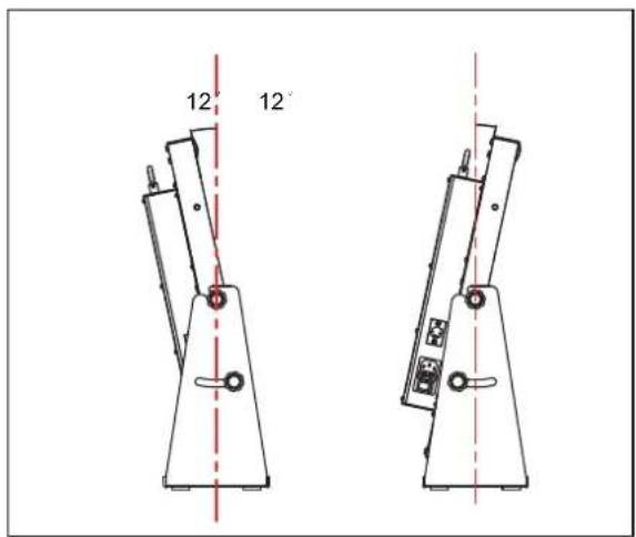
Fix the other 2 screws to the downside screw holes. Adjust monitor angle of ±12° by the downside screws.
Caution:
- Be careful not to pinch your fingers in the moving parts. The Max tilt angle is down 12° and up 12°, please make sure the setup location is stable, to prevent the monitor falling down.
- Place the monitor on a mat to avoid scratching the table surface.

Rear panel

① SFP terminal
Input terminal for 12G/6G/3G/HD/SD-SDI SFP optical fiber receiver adaptor.
● The SFP adaptor is optional purchased.
2 E. AUDIO SDI (OUT) terminal (BNC)
Output terminal for the SDI IN1 or SFP IN signal, supports 12G/6G/3G/HD/SD.
③ E. AUDIO SDI (IN) terminals (BNC)
Input terminals for the SDI signals:
SDI IN1: 12G/6G/3G/HD/SD
SDI IN2/3/4: 3G/HD/SD
● The SDI terminals accept also EMBEDDED AUDIO signals including up to 16 audio channels with a sampling frequency of 48 kHz.
4 HDMI terminal
Input / Output terminal for HDMI signals.
- Will not display or output HDCP protected contacts.
5 ETHERNET
1000M high speed RJ45 ethernet port, for webserver IP external control. ( page 17)
6 GPI terminal
Terminal for controlling the monitor by GPI remote. ( Page 16.)
7 RS485 UMD terminal
Terminal for controlling the monitor by TSL UMD Tallyman system. (See page 17.)
8 DC-IN terminal
Connect with DC12V-17V 4-pin XLR power adapter.
(Pin 1: Negative, Pin 4: Positive)
● Make sure the DC adaptor load matches with the power consumption of the monitor.
9 AC-IN terminal
Connect the provided AC power cord to an AC outlet, support AC 100-240V, 50/60Hz, with 250V fuse.
10 AC Switcher
Switch to OFF will cut off AC power completely.
Note for connections
• Before making any connections, turn off all the equipment. - Use a cord whose plugs correctly match the terminals on this monitor and the equipment. - Plugs should be firmly inserted; poor connections could cause noise. - When unplugging a cord, be sure to grasp its plug and pull it out. - DO NOT connect the power cord until all connections are complete. * Refer also to the user manual of each piece of equipment.
Index of Parts and Functions (cont.)

Front panel

Tally lamp
This lamp is controlled by the tally function of the Make contact terminal. (See page 16.)
You can select the color of the tally lamp from "Green", "Red", or "Yellow".
![graph TD A["Circle"] --> B["Arrow to Top"] B --> C["Arrow to Bottom"] C --> D["Arrow to Top"] D --> E["Arrow to Bottom"] E --> F["Arrow to Top"] F --> G["Arrow to Bottom"] G --> H["Arrow to Top"] H --> I["Arrow to Bottom"] I --> J["Arrow to Top"] J --> K["Arrow to Bottom"]](/content/2026/06/1366197/images/8dea974b34bfa2d381fec8a47ed6bc30b0f6de70832c2f755a7e21b437d229b1.jpg)
1 Speaker:
For SDI/HDMI embedded audio monitoring.
● The speaker will not work if earphone is plugged in.
2 Rotary knobs:
VOLUME: Adjust the sound volume from 0-100.
- Press down the VOLUME knob, the volume will be 0 (mute). CHROMA: Adjusts the picture chroma from -100 to +100. BRIGHT: Adjusts the picture brightness from -100 to +100. CONTRAST: Adjusts the picture contrast from -100 to +100.
- Press down the BRIGHT/CONTRAST/SATURATION knobs, the parameters will recover to default value 0.
3 Direction Keys:
Includes Up, Down, Left, Right 4 direction keys for Menu operation. ( page 9.)
4 Menu Key:
Press to switch on Menu system and operate by direction keys.
5 WFM Key:
Press to switch on/off the Waveform scope.
6 INFO Key
Press to switch on/off all the on-screen overlay information, including video scopes, audio meters, UMD, timecode, markers, etc.
- Press INFO can quit the Menu system at any time.
7 FUNCTION Keys
Provide F1 / F2 / F3 / F4 / F5 / F6 function keys to assign monitor functions and switch them on/off quickly. (page 19.)
8 INPUT SELECTION keys
Select input sources directly:
- SDI 1 / SFP: Press to switch to the SDI IN-1 terminal input. Press again to switch to the SFP terminal input.
- SDI 2: Press to switch to the SDI IN-2 terminal input.
- SDI 3: Press to switch to the SDI IN-3 terminal input.
- SDI 4: Press to switch to the SDI IN-4 terminal input.
- 4x3G: Press to switch to Quad-link 4x3G SDI 2SI interleave mode. Press again to switch to 4x3G SDI Quad split mode. ● The 4x3G source requires inputs of all SDI IN1,2,3,4.
- HDMI: Press to switch to the HDMI terminal input.
● The key light will indicate the current input source.
9 POWER ON/OFF
Press to switch on or off the monitor:
The standby power consumption is less than 0.5W, complying with ErP rules. To completely cut off power, please switch off the AC input switch or disconnect the DC cable.
10 PHONE jack
3.5mm earphone socket, for SDI/HDMI embedded audio monitoring.
11 USB LUT (The USB file system only supports FAT32.)
- Firmware upgrade: Plug in USB stick with firmware, operate Menu to upgrade the monitor. (page 19.)
- User 3DLUT upload:
Plug in USB stick with user created LUTs, operate Menu to upload to the monitor. (page 11.)
- Auto calibration:
Plug in color sensor probe into the USB port, operate Menu to start auto calibration. (page 12.)
On the Information Display

1 Time code (SDI)
Under SDI input, the monitor can display Time code information (LTC, VITC1&2). If no Time code info is detected, it will display "TC UNLOCKED".
2 On screen TALLY
Display TALLY signal from GPI port. (page 16.)
3 UMD
Display TSL 3.1/4.0 UMD or User input Source ID. (page 17.)
4 Color Checker
Display color gamut chart and Delta chart for last calibrated value and current measured value. (page 10.)
5 Lissajous
Display audio Lissajous pattern. (page 15.)
6 Audio VU/PPM meters
Display meters of SDI/HDMI embedded audio. The audio meter on screen positions, markers and background colors are adjustable. (page 15.)
7 Histogram
Parallel display R/G/B/Y histogram for SDI and HDMI video. (page 14.)
8 Vector scope
Display vector scope with 100% and 75% markers for SDI and HDMI video. The vector scope pattern display positions, colors, background are adjustable. (page 14.)
9 Waveform
Display waveform scopes for SDI and HDMI video with markers. The display waveform can be selected from Y/Cb/Cr/R/G/B /RGB types, and single line display mode selectable. The waveform display positions, colors, background are adjustable. (page 14.)
On the Status Display
| Main Menu | Status | |
| Exit&Status > | Channel | XXX 1 |
| Picture Adjustments > | Format | XX 2 |
| Signal and Color > | Video Lumina Range | XXXX 3 |
| Signal Scanning > | YUV Color Matrix | XXXX 4 |
| Tool & Information > | Processing Color Space | XXX 5 |
| Audio > | Color Temperature | XXX 6 |
| External Control > | Scanning | XXX 7 |
| System Setting > | Loaded Profile | XXX 8 |
| Firmware Version | XXX 9 | |
Press the "MENU" button, and the main menu will pop up from the top left of the screen, displaying the current working status, including:
1. Channel
Displays the currently displayed input source. When Multiview is enabled, the channel displays Multiview.
2. Format
Displays the video format of the current input source.
- If no video is detected in the current input source, it will display "No Signal".
- When Multiview is enabled, the formats of the 4-channel SDI signals will be displayed respectively.
3. Video Luma Range
Displays the currently set video luma level range value.
4. YUV Color Matrix
Displays the currently set YUV color matrix.
5. Processing Color Space
Displays the currently set color space.
6. Color Temperature
Display the current set of color temperature.
7 Scanning
Display the current set of scan mode.
8 Loaded Profile
Display the current loaded user profile.
9 System Version
Display the current firmware version.

The Operation Procedure
1 Press the "MENU" button to display the Main Menu. 2 Press "▲" and "▼" to select submenu, the selected submenu highlights in yellow; Press "▶" to apply and enter into the selected submenu item. 3 Press "▲" and "▼" to select the item to be set from the submenu; Press "►", the selected item and its parameters will be highlighted in yellow. 4 Press "▲" and "▼" to adjust the selected item; Press "►" or "MENU" to apply and save the settings. 5 Press "◀" to quit submenu; Press "◀" again to quit the Main Menu. 6 Press "INFO" can quit Menu system at any time.
Note
The items in gray means not available to set up.
If there is no operation in a period of time, the menu will automatically save settings and quit. The menu quit time can be set from OSD submenu.
If Key Inhibit is turned on, except the Key Inhibit submenu, all other items are not available to operate. Please turn off the key inhibit to enable the Menu operation.

Menu Transition Diagram
![graph TD A["MENU"] --> B["Exit&Status"] A --> C["Picture Adjustments"] A --> D["Signal and Color"] A --> E["Signal Scanning"] A --> F["Tools&Information"] A --> G["Audio"] A --> H["External Control"] A --> I["System Setting"] B --> J["Contrast"] B --> K["Brightness"] B --> L["Chroma"] B --> M["Sharp…](/content/2026/06/1366197/images/6b5f5073aec854d29e4cf76513b9c1f7b1e5aba98ba5a2ab50e838a707992d1d.jpg)
Main Menu
Picture Adjustments
Setting for the picture preference.
| Item | To do | Setting value |
| Contrast | Adjusts the contrast of the display. | -100 to +100 |
| Brightness | Adjusts the brightness of the display. | -100 to +100 |
| Chroma | Adjusts the saturation of the display. | -100 to +100 |
| Sharpness | Adjusts the sharpness of the display. | 0 to 100 |
| Backlight | Adjusts the backlight of the display. | 0 to 100 |
| Back | Return to previous menu | |
| Exit | Exit Main Menu |
Signal and Color
Settings about video colors
| Item | To do | Setting value | |
| Video Lumina Range*1 | Select a range to match with input video | 0-1023, 4-1019, 64-940, 64-1023 | |
| YUV Color Matrix | Select the input YUV color matrix | Auto, BT.601, BT.709, BT.2020 | |
| Display Color Processing | Select the color gamut to display | LCD Panel, DCI-P3, Rec.709, Rec.2020 | |
| Gamma | Select the Gamma correction value | 1.0, 1.8, 2.2, 2.4, 2.6, PQ1000, HLG1000, S-Log3 | |
| SoftClip *2 | Set SoftClip | OFF,ON | |
| HLG System Gamma*3 | Select the HLG System Gamma correction value | 1.0,1.1,1.2,1.3,1.4,1.5 | |
| D-Log to 709*4 | Select a camera log LUT to convert to REC.709 | OFF, J-Log1, Log-C, S-Log2, C-Log, V-Log, RedLogFilm, S-Log3, User-Log | |
| D-Log to PQ*5 | Select a camera log LUT to convert to PQ1000 | OFF,ARRI_LogC_PQ,Canon_CLog2Cin_PQ, Canon_CLog3Cin_PQ,Panasonic_VLog_PQ,RED_L3G10_PQ, Sony_SLog3_Cin_PQ,Sony_SLog3_SG3_PQ | |
| D-Log to HLG*6 | Select a camera log LUT to convert to HLG1000 | OFF,ARRI_LogC_HLG,Canon_CLog2Cin_HLG, Canon_CLog3Cin_HLG, Panasonic_VLog_HLG, RED_L3G10_HLG,Sony_SLog3_Cin_HLG, Sony_SLog3_SG3_HLG, | |
| Import LUT's *7 | Select a LUT position to upload User created 3DLUT cube | None, 3DLut.cube, User-Log.cube | |
| Color Temperattrue | Select a Color Temperature | 2000K-10000K (Take a step of 100K) USER 1, USER 2, D55, D65, D75, D93 | |
| User Adjustments | Select a User Temperature and adjust the RGB Gain/Bias value(Only available when Color temperature is set to USER1 or USER2) | User Temp: 2000K-10000K(Take a step of 100K) D55,D65,D75,D93 Red Gain: -100~+100 Red Bias: -100~+100 Green Gain: -100~+100 Green Bias: -100~+100 Blue Gain: -100~+100 Blue Bias: -100~+100 | |
| Auto Calibration *8 | Probe Select *9 | Select a probe to use | X-rite I1 Pro OEM, Jeti Specbos 1211 |
| Type | Set calibration time | Quick mode, Precise mode | |
| Start Calibration*10 | Start Calibration | No, Yes | |
| Measure *11 | Measure current color | No, Yes | |
| Back | Return to previous menu | ||
| Exit | Exit Main Menu | ||
| Color Checker | Switch on the color gamut and display | OFF, ON | |
| Back | Return to previous menu | ||
| Exit | Exit Main Menu | ||
Menu Configuration (cont.)
*1 Video Lumina Range
Set Video Lumina Range to match with input video.
The default lumina range is 64-940 for broadcast application.
*2 Softclip
Only displays in PQ1000.
*3 HLG System Gamma
Only displays in HLG1000.
*4 D-Log to 709
D-Log to 709 only displays in Rec.709 mode.
| Upload Position | Description |
| J-Log1.cube | JVC J-Log1 to Rec709 3DLUT cube |
| Log-C.cube | ARRI Log-C to Rec709 3DLUT cube |
| S-Log2.cube | SONY S-Log2 to Rec709 3DLUT cube |
| S-Log3.cube | SONY S-Log3 to Rec709 3DLUT cube |
| C-Log.cube | Canon C-Log to Rec709 3DLUT cube |
| V-Log.cube | Panasonic V-Log to Rec709 3DLUT cube |
| RedLogFilm.cube | Red Log to Rec709 3DLUT cube |
| User-Log.cube | User 3DLUT cube upload |
*5 D-Log to PQ
D-Log to PQ only displays in Rec.2020 with PQ1000 mode.
| Upload Position | Description |
| ARRI_LogC_PQ | ARRI_LogC_PQ to Rec.2020 PQ |
| Canon_CLog2Cin_PQ | Canon_CLog2Cin_PQ to Rec.2020 PQ |
| Canon_CLog3Cin_PQ | Canon_CLog3Cin_PQ to Rec.2020 PQ |
| Panasonic_VLog_PQ | Panasonic_VLog_PQ to Rec.2020 PQ |
| RED_L3G10_PQ RED_L3 | RED_L3G10_PQ to Rec.2020 PQ |
| Sony_SLog3_Cin_PQ | Sony_SLog3_Cin_PQ to Rec.2020 PQ |
| Sony_SLog3_SG3_PQ | Sony_SLog3_SG3_PQ to Rec.2020 PQ |
*6 D-Log to HLG
D-Log to HLG only displays in Rec.2020 with HLG1000 mode.
| Upload Position | Description |
| ARRI_LogC_HLG | ARRI_LogC_HLG to Rec.2020 HLG |
| Canon_CLog2Cin_HLG | Canon_CLog2Cin_HLG to Rec.2020 HLG |
| Canon_CLog3Cin_HLG | Canon_CLog3Cin_HLG to Rec.2020 HLG |
| Panasonic_VLog_HLG | Panasonic_VLog_HLG to Rec.2020 HLG |
| RED_L3G10_HLG RED_L3G10_HLG to Rec.2020 HLG | |
| Sony_SLog3_Cin_HLG Sony_SLog3_Cin_HLG to Rec.2020 HLG | |
| Sony_SLog3_SG3_HLG Sony_SLog3_SG3_HLG to Rec.2020 HLG | |
*7 Import LUT's
The monitor has built-in calibrated 3DLUT cube, De-log 3DLUT cube, User 3DLUT cube and PQ1000, HLG1000 HDR LUTs.
To upload user LUT or overwrite the built-in LUTs:
- Make sure the 3DLUT format should be 17x17x17 cube, and the 1DLUT format should be csv.
- Rename the LUT or overwrite the built-in LUTs: (attention to the capital letters), and copy into USB stick root directory.
- Insert the USB stick onto monitor USB port on the FRONT panel, select the corresponding upload position to import the new LUT.
*8 Auto Calibration
The monitor has 3DLUT calibration software built-in, and supports the following color sensor probe to directly plug into front USB port.
When start calibration, the monitor will generate standard colors and the color sensor will read the colors one by one and upload result to the monitor by USB connection.
The monitor will compare the generated colors with the sensor-read colors to work out a 3D LUT cube and calibrate itself automatically.
*9 Probe Select
The monitor supports the following probe models:
| Brand Model | |
| i1 DISPLAY E0DIS3-DC0E (JVC dedicated version)X-rite | |
| Specbos 1211JETI | |
*10 Start Calibration
Steps:
(1) Place the monitor in a dark room. Switch on the monitor. (2) Plug the color sensor (X-rite i1 or Jeti Specbos 1211) into the front USB port of the monitor. (3) Enter Auto Calibration - Probe Select to select the correct color sensor probe. (4) Enter Auto Calibration - Type to select quick mode or precise mode.
Calibration time
| Sensor probe Quick | mode Precise mode | |
| 15 minX-rite i1 | 30 min | |
| 45 min | 90 minJETI Specbos 1211 |
(5) Enter Auto Calibration - Start Calibration, and the monitor will display information and probe position mark.

FRONT USB port connection
Auto Calibration
Please make sure the monitor is in a dark room, and the sensor probe is placed in the center marker and close to the screen.
Select MENU to start!
MENU: OK
INFO: Quit
(6) Select "YES", and the auto calibration will start. The monitor will generate different color patterns one by one, and display the calibration progress in percentage. (7) After the calibration, the "Before Calibration" and "After Calibration" chart pops up in the center of the screen.


Press "INFO" to quit the calibration process at any time. The monitor will not be calibrated until the process reaches 100%.
*11 Measure
The monitor has been calibrated in the factory and may need to be re-calibrated after a period of time.
Before re-calibration, the measure function can check the current color to compare with the last calibrated color, to decide if the monitor needs to be re-calibrated.
Connect the sensor probe and place it onto the correct position as in the calibration step.
Enter Auto Calibration - Measure.
The monitor will generate several colors and finish measuring within 30 seconds. Then it will display the result as:

● The color chart can be switched on/off at:
Menu - Tool & Information - Color Checker - ON/OFF.
Signal Scanning
Settings for picture scan, zoom, flip, etc.
| Item | To do | Setting value |
| Scanning*1 | Select a mode to fit video to LCD panel | Panel Fit, Pixel to Pixel, Native |
| Zoom Area Selection *2 | Select an area to zoom-in | OFF, Top Left, Top, Top Right, Left, Center, Right, Bottom Left,Bottom, Bottom Right |
| Freeze Frame*3 | Switch on/off the freeze frame | OFF, ON |
| Odd/Even Frame*4 | Switch on odd or even lines display mode | OFF, Odd Mode, Even Mode |
| H/V Delay*5 | Switch on/off the H/V delay mode | OFF, ON |
| Low Latency Mode*6 | Switch on/off the low latency mode | OFF, ON |
| Back | Return to previous menu | |
| Exit | Exit Main Menu |
*1 Scanning
Panel Fit: Stretch the video to fit the full screen.
Native: Only displayed at 4096*2160, black edges appear above and below the screen.
*2 Zoom Area Selection
| Top Left | Top Right |
| Bottom Left | Bottom Right |
| Top | |
| Bottom |
| Left | Right |
| Center |
Freeze Frame is not displayed at 4x3G.
*4 Odd/Even Frame
Odd/Even Frame is not displayed in all p formats.
*5 H/V Delay
H/V Delay is not displayed on HDMI channel.
*6 Low Latency Mode
Low Latency Mode is a special image processing mode for lip-sync monitoring.
For Progressive (p) formats, the monitor is low latency itself, whether Low Latency Mode is on or off.
For Interlace (i) or Progressive Segmented Frame (psf) formats, turning on Low Latency Mode will get lower latency.
Video/Audio latency chart:
| SDI formats | Low latency mode OFF | Low latency mode ON |
| 4096x2160 60p | 0.01 frame | 0.01 frame |
| 4096x2160 50p | 0.1 frame | 0.1 frame |
| 4096x2160 30p | 0.51 frame | 0.51 frame |
| 4096x2160 25p | 0.6 frame | 0.6 frame |
| 4096x2160 24p | 0.6 frame | 0.6 frame |
| 3840x2160 60p | 0.01 frame | 0.01 frame |
| 3840x2160 50p | 0.1 frame | 0.1 frame |
| 3840x2160 30p | 0.51 frame | 0.51 frame |
| 3840x2160 25p | 0.6 frame | 0.6 frame |
| 3840x2160 24p | 0.6 frame | 0.6 frame |
| 2048x1080 60p | 0.01 frame | 0.01 frame |
| 2048x1080 50p | 0.1 frame | 0.1 frame |
| 2048x1080 30p | 0.51 frame | 0.51 frame |
| 2048x1080 25p | 0.6 frame | 0.6 frame |
| 2048x1080 24p | 0.6 frame | 0.6 frame |
| 1080 60p | 0.01 frame | 0.01 frame |
| 1080 50p | 0.1 frame | 0.1 frame |
| 1080 30p | 0.51 frame | 0.51 frame |
| 1080 25p | 0.6 frame | 0.6 frame |
| 1080 24p | 0.6 frame | 0.6 frame |
| 1080 24psf | 2 frames | 0.6 frame |
| 1080 60i | 2 frames | 0.01 frame |
| 1080 50i | 2 frames | 0.1 frame |
| 720 60p | 0.01 frame | 0.01 frame |
| 720 50p | 0.1 frame | 0.1 frame |
Tools & Information
Setting for Vector scope and Histogram patterns
| Item | To do | Setting value | |
| Focus Assist | Switch on focus assist mode and select color | OFF, Blue, Red | |
| Zebra | Switch on zebra stripes for over exposed image | OFF, ON | |
| False Color *1 | Switch on false color mode | OFF, ON | |
| Blue Only | Switch on blue only mode | OFF, ON | |
| Marker | Marker | Switch on the marker display | OFF, Marker, Safety Marker, ALL |
| Marker Select | Select the marker ratio | 16:9,15:9,14:9,13:9, 4:3, 2.39:1, 2.35:1, 2:1, 1.85:1, Custom1, Custom2 | |
| Horizontal | Set the horizontal axis scale | 50%~99% | |
| Vertical | Set the vertical axis scale | 50%~99% | |
| Safety Area | Set safety area percentage | 80%~99% | |
| Fit Marker | Set safety area to fit marker ratio or not | OFF, ON | |
| Center Marker | Switch on the center cross marker | OFF, ON | |
| Marker Color | Select a color for marker | White, Red, Green, Blue, Black, Gray | |
| Marker Outside | Marker outside color setting | OFF, Black, Gray | |
| Back | Return to previous menu | ||
| Exit | Exit Main Menu | ||
| Histogram | Histogram | Turn on/off the Histogram pattern | OFF, ON |
| Histogram Blending | Histogram background transparency selection | OFF, High, Low | |
| Back | Return to previous menu | ||
| Exit | Exit Main Menu | ||
| Waveform | Waveform | Switch on the Waveform pattern | OFF, ON |
| WFM Type | Waveform type select | Y, Cb, Cr, R, G, B, RGB | |
| WFM Position | Waveform on screen display position setting | Bottom Left, Bottom Right, Top Left, Top Right | |
| WFM Blending | Waveform background transparency selection | OFF, High, Low | |
| WFM Color | Waveform pattern color setting | White, Green, Color | |
| WFM Single Line *2 | Switch on single line waveform mode | OFF, ON | |
| WFM Line Count | Select a line for the single line waveform | 1-2160 | |
| Back | Return to previous menu | ||
| Exit | Exit Main Menu | ||
| Vector | Vector | Switch on vector scope pattern | OFF, ON |
| Vector Position | Vector scope on screen display position setting | Bottom Left, Bottom Right, Top Left, Top Right | |
| Vector Blending | Vector scope background transparency selection | OFF, High, Low | |
| Vector Color | Vector scope pattern color setting | White, Green, Color | |
| Back | Return to previous menu | ||
| Exit | Exit Main Menu | ||
| Time Code *3 | Switch on Time code display | OFF, ON | |
| Back | Return to previous menu | ||
| Exit | Exit Main Menu | ||
*1: False Color
Under false color mode, there is a color chart on the bottom of screen for reference.
*2: WFM Single Line
Turn on the Waveform single line mode, the monitor will display waveform for only 1 line video.
Select a line at WFM Line Count by using "▲" and "▼".
Under WFM single line mode, outside the Menu system, directly pressing "▲" and "▼" can select lines.

WFM Single Line: OFF

WFM Single Line: On
*3 Time code
Time codes are not displayed on the HDMI channel.
When the menu opens, the time code appears at the bottom of the screen; otherwise, it appears at the top.
Audio
Setting for video/audio analysis functions
| Item | To do | Setting value |
| Volume | Adjust volume | 0~100 |
| Left Channel | Select an audio channel to output left | Channel 1~Channel 16 |
| Right Channel | Select an audio channel to output right | Channel 1~Channel 16 |
| Audio Group*1 | Select four audio channels to display | Group 1,Group 2, Group 3, Group 4 |
| Audio Bar | Switch on the audio meter display | OFF, ON |
| Bar Position | Change on screen display position of the audio bar. | Bottom Right, Top LeftTop Right, Bottom Left |
| Bar Blending | Adjust the audio bar pattern background transparency. | OFF, Low, High |
| Bar Type*2 | Switch on the mark and alert info of audio meter pattern. | TYPE1, TYPE2 |
| Lissajous | Switch on the audio Lissajous pattern display | OFF, ON |
| Lissajous Position | Change on screen display position of the Lissajous pattern. | Top Left, Top Right,Bottom Left, Bottom Right, |
| Back | Return to previous menu | |
| Exit | Exit Main Menu |
*1: Audio Group
When Multiview is switched on, the audio bar only displays 4 audio channels. This menu allows you to choose the 4 audio channels that need to be displayed.
*2: Bar Type
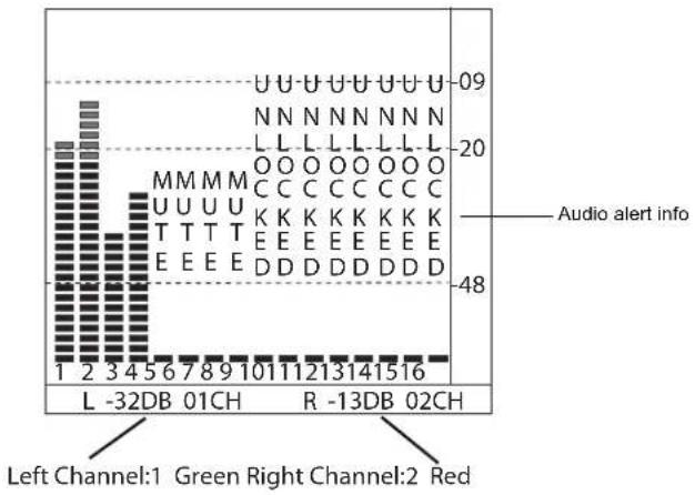
The audio bar displays up to 16 channels of audio level meters.
TYPE1 displays audio meters only.
The TYPE2 displays audio dB mark, audio alert info, and left channel and right channel selection.
TYPE 1 TYPE 2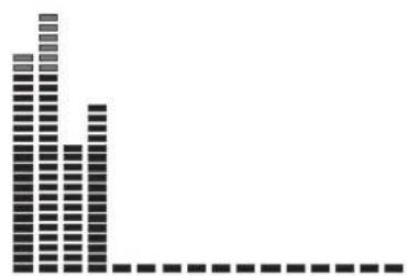
External Control
Setting for TALLY, UMD, IP control to the monitor
| Item | To do | Setting value | |
| Tally Setting OFF, ON, Blinking on-screen tally display mode | |||
| Tally Position | Select the display position of on-screen tally | Top, Bottom | |
| GPI *1 | GPI Control | Enable GPI control | OFF, ON |
| 1 Pin | Assign functions to the GPI terminals | SFP, SDI1, SDI2, SDI3, SDI4, 4xSDI(2SI), 4xSDI(SQ), HDMI, Red Tally, Green Tally, Yellow Tally, Time code, Color Temp, Flip mode, Freeze Frame, WFM Single Line, UMD, Marker, H/V Delay, Audio bar, Zebra, Vector, Low Latency Mode, Histogram Odd/Even Frame, Lissajous, Focus Assist, False color | |
| 2 Pin | |||
| 3 Pin | |||
| 4 Pin | |||
| 5 Pin | |||
| 6 Pin | |||
| Back | Return to previous menu | ||
| Exit | Exit Main Menu | ||
| UMD *2 | Switch on the UMD display | OFF, ON | |
| UMD Mode | Select the UMD source | Internal, External | |
| UMD Position | Select the display position of UMD | Top, Bottom | |
| UMD Size | Select UMD display size | Large, Small | |
| UMD Color | Select UMD display color | White, Red, Green, Blue, Black, Gray | |
| UMD Blending | Select UMD background transparency | OFF, Low, HIGH | |
| Source ID | Edit internal UMD letters | A-Z, a-z, 0-9, Space, &()*+,-./:<=_ | |
| TSL Address | TSL UMD setting | 1~126 | |
| TSL Baud Rate | 115200 | ||
| TSL Data Bits | 8 | ||
| TSL Parity | None | ||
| TSL Stop Bits | 1 | ||
| IP *3 | Set monitor IP address for webserver remote control | 192.168.001.200 | |
| Net Mask | 255.255.255.000 | ||
| Gateway | 192.168.001.001 | ||
| Port(1024~65535) | 08080 | ||
| Back | Return to previous menu | ||
| Exit | Exit Main Menu | ||
*1 GPI control
Connect GPI remote controller with "GPI" port of the monitor rear panel.
Switch on the "GPI Control".
Assign functions for GPI 1-6.
Control the GPI 1-6 pin terminals to short-circuit with the GND pin terminal, to enable the assigned function, and disconnecting (opening) to disable the functions.
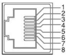
GPI
| Pin No | Pin name |
| 1 GPI 1 | |
| 2 GPI 2 | |
| 3 GPI 3 | |
| 4 GPI 4 | |
| 5 GPI 5 | |
| 6 GPI 6 | |
| 7 | NC |
| 8 | GND |
The GPI controlled TALLY signal will display both front TALLY light and on-screen TALLY:

Menu Configuration (cont.)
*2 UMD control
Select UMD mode to "External" will enable TSL UMD control. TallyMan system connection:

RS485 IN

RS485 OUT
They are female terminals.
| Pin No | IN terminal signal OUT terminal signal | |
| 1 | GND | GND |
| 2 | NC | NC |
| 3 | RXD- | RXD- |
| 4 | NC | NC |
| 5 | NC | NC |
| 6 | RXD+ | RXD+ |
| 7 | TXD- | TXD- |
| 8 | TXD+ | TXD+ |
Serial connections:![graph LR A["TallyMan"] --> B["RS-485 IN RS-485 OUT"] B --> C["RS-485 IN"] C --> D["RS-485 OUT"] D --> E["RS-485 IN"] E --> F["..."]](/content/2026/06/1366197/images/5ca8ddfd2ec664a534c62cc2fda5e47bcf0bef4b865a3b00bcda5c4882f6bd2e.jpg)
*3 Webserver IP Control
Connect the monitor ETHERNET port into LAN, and the monitor can be remote controlled by webpage.

ETHERNET
| Pin No | Pin name |
| 1 TX+ | |
| 2 TX- | |
| 3 RX+ | |
| 4 | |
| 5 | |
| 6 RX- | |
| 7 | |
| 8 |
Enter Menu- External Control - IP/Net Mask/Gateway/Port to set the monitor addresses. Set the computer Ethernet IP address at the same LAN environment as the Monitor.

2) Launch any of a web browser on the computer, and enter URL: Monitor IP + port (for example 192.168.1.99:8080). The webserver control page will be displayed.

Monitor IP address Monitor port address
- Use crossed wired cable for computer-monitor directly connection. Use straight-through wired cable for Router connection.
- Please seek help from your webmaster for any network connections.
Webserver page control interface

DT-U series

System Setting
User profile saving, firmware update.
| To do | Setting valueltem | ||
| Multiview *1 | Switch on multiview | OFF,ON | |
| Load Profile *2 | Global | Select a user profile for all input sources | User 1-8, OFF |
| SFP | Select a user profile for SFP input only | User 1-8 | |
| SDI1 | Select a user profile for SDI 1 input only | ||
| SDI2 | Select a user profile for SDI 2 input only | ||
| SDI3 | Select a user profile for SDI 3 input only | ||
| SDI4 | Select a user profile for SDI 4 input only | ||
| 4xSDI(SQ) | Select a user profile for Quad split 4x3G input only | ||
| 4xSDI(2-SI) | Select a user profile for 2SI interleave 4x3GSDI input only | ||
| HDMI | Select a user profile for HDMI input only | ||
| Multiview | Select a user profile for Multiview input only | ||
| Back | Return to previous menu | ||
| Exit | Exit Main Menu | ||
| Save Profile | Save all the current menu settings to User profile, support rename user profile when saving. | User 1-8 | |
| Key Brightness | Set front key board light brightness | OFF, LOW, HIGH | |
| OSD TIME (Sec) | Select a time to quit menu if there's no operation | 5-180 | |
| F1 | Assign functions to the function keys F1 - F6 on the front key board | Time code, Color Temp,Flip mode, Freeze Frame, WFM Type, WFM Single Line, UMD, Marker, H/V Delay, Blue Only, Audio bar, Zebra, Vector, Low Latency Mode, Histogram, Odd/Even Frame, Lissajous, Focus Assist, False color, Multiview | |
| F2 | |||
| F3 | |||
| F4 | |||
| F5 | |||
| F6 | |||
| Green Mode | Turn down or switch off the LCD backlight to save energy | Black Backlight, Gray Backlight | |
| Idle Duration | Select a time to enter Green mode if there's no operation | 30Sec, 1Hour, 2Hour, 4Hour, OFF | |
| Key Lock *3 | Select a key lock mode | OFF, Lock All, Lock Rotary Knobs, Lock Key Buttons | |
| Closed Caption Switch on closed caption | NO, OFF | ||
| Firmware Update *5 | Enter firmware update | NO, YES | |
| System Reset | Reset all the monitor settings | NO, YES | |
| Back | Return to previous menu | ||
| Exit | Exit Main Menu | ||
*1 Multiview
Switch on Multiview, the monitor can display 4 different formats SDI signal, supported displaying 1080P/1080I/1080PsF/4K, fourth channel signal can also display HDMI signal, support HD and above standard, as shown in the following figure:
| 4K(SDI 1 IN) | 1080P(SDI2 IN) |
| 1080PsF(SDI3 IN) | 1080I(SDI4 IN orHDMI IN) |
When Multiview is selected:
1. Video Lumina Range, YUV Color Matrix, Color Processing, Gamma and UMD of each channel can be set respectively. 2. Some menu functions are turned off or displayed in gray.
*2 Load Profile
Select "Global" to "User 1-8", to assign the user profile to all the input sources; Select "Global" to "OFF", the user profiles can be assigned to each input source individually.
*3 Key Lock
Select different keys to lock:

All
● The MENU button can be operated when key locked. - Press the locked buttons or knobs, the screen will display:

*4 Closed Caption
Only SDI signal system has closed caption menu items.
*5 Firmware Update
The monitor firmware can be updated by front USB port.
Update steps:
(1) Download the latest firmware file (DT-UXX Vxx YYMMDD.zip) to the root directory of a USB disk. (2) Turn on the monitor and plug the USB disk into the front USB port. (3) Go to MENU - System Setting - Firmware Update, and the monitor will update automatically. (4) When the update is successful, turn off the monitor using the front POWER button and then turn it on again.
UPDATE
Do you want to update now?
Select MENU to start!
MENU: OK
INFO: Quit
- Please copy only one firmware for one model monitor into the USB root directory.
- Caution! Do not cut off power during firmware update.
General
| Model name | DT-U17 DT-U24 | |
| Type Multi format LCD monitor Multi format LCD monitor | ||
| Screen size | 17.3" | 23.8" |
| Aspect ratio | 16:9 | 16:9 |
| Compliant video signal format | “Available signals” on page 23 | |
| Format | 12G SDI: SMPTE ST20806G SDI: 3840x2160 30/25/24p3G SDI: SMPTE-425M-A/BHD SDI: BTA S-004C, SMPTE292M, SMPTE-425M-A/B, SMPTE-274M, SMPTE-RP211, SMPTE-296MSD SDI: SMPTE-125M, ITU-R BT.6562K: SMPTE ST 2048-1: 2011EMBEDDED AUDIO: SMPTE299M, SMPTE272M | |
| Audio output Internal speaker: 1.25W+1.25W(8Ω) | ||
| Operating conditions(Slightly variable depending on ambient conditions for installation.) | Operating temperature: 0°C - 50°C (32°F - 122°F)Operating humidity: 20% - 90% (non-condensing) | Operating temperature: 0°C - 50°C (32°F - 122°F)Operating humidity: 20% - 90% (non-condensing) |
| Power requirements | AC 120V/AC 220- 240 V, 50 Hz/60 Hz;DC12 - 17V | AC 120V/AC 220 - 240 V, 50 Hz/60 Hz;DC12 - 17V |
| Rated current | 0.6A (AC 100V)/0.3A(AC 240V)/5A(DC 12-17V) | 0.8A (AC 100V)/0.4A(AC 240V)/6A(DC 12-17V) |
| External dimensions(with the stand)(excluding protruding parts) | Width: 442.30mm(17 13/32")Height: 341.56mm(13 7/16")Depth: 145.00mm(5 11/16") | Width: 588.40mm(23 3/16")Height: 419.59mm(16 1/2")Depth: 145.00mm(5 11/16") |
| External dimensions(without the stand)(excluding protruding parts) | Width: 442.30mm(17 13/32")Height: 310.89mm(12 1/4")Depth: 88.72mm(3 1/2") | Width: 588.40mm(23 3/16")Height: 388.92mm(15 5/16")Depth: 88.70mm(3 1/2") |
| Weight(without the stand) | 5.5kg | 8.5kg |
| Weight(with the stand) | 5.9kg | 8.9kg |
| Accessories AC power cord x 1 | ||
LCD panel
| Model name | DT-U17 | DT-U24 | |
| Effective screen size | Width | 381.89mm(15 1/32") | 527.04mm(20 3/4") |
| Height | 214.81mm(8 7/16") | 296.46mm(11 11/16") | |
| Diagonal | 438.16mm(17 1/4") | 604.70mm(23 13/16") | |
| Number of pixels displayed | 3840 x 2160 | 3840 x 2160 | |
| Number of colors displayed | 16.7M | 1.07B | |
| Viewing angle (TYP.) | 178° (H), 178° (V) | 178° (H), 178° (V) | |
| Brightness (TYP.) | 300 cd/m2 | 350cd/m2 | |
| Contrast ratio (TYP.) | 800:1 | 1000:1 | |
Input/output terminals
| Video | HDMI | HDMI connector x 2(IN and OUT) |
| E. AUDIO 12G/6G/3G/HD/SD SDI | Digital signal input (compatible with EMBEDDED AUDIO signals): auto detection, 2 line, BNC connector x 2 | |
| E. AUDIO 3G/HD/SD SDI | Digital signal output (compatible with EMBEDDED AUDIO signals): auto detection, 2 line, BNC connector x 2 | |
| Audio | AUDIO (MONITOR OUT) Speaker: 1.25W+1.25W(8 Ω) 3.5mm phone | |
| External control | GPI (MAKE) | “GPI control” on page 16. |
| UMD (RS-485) IN&OUT | “UMD control” on page 17. | |
| Ethernet IP (RJ-45) | “Webserver IP control” on page 17&18. | |
Specifications (cont.)
Dimensions
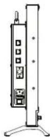
Unit: mm




Available signals
The following signals are available for this monitor.
Video signals
| FormatsNo. | Signal format shown in the Status Display as Inp | ||||||
| SDI 1 & SFP SDI 2/3/4 Quadlink SDI | HDMI | SDI & SFP HDMI | |||||
| 1 | 720×480/60I | √ | √ | — | — | 720*480I60 | 720*480I60 |
| 2 | 720×480/60P | — | — | — | √ | 720*480P60 | 720*480P60 |
| 3 | 720×576/50I | √ | √ | — | — | 720*576I50 | 720*576I50 |
| 4 | 720×576/50P | — | — | — | √ | 720*576P50 | 720*576I50 |
| 5 | 1280×720/23.98P | √ | √ | — | √ | 1280*720P23.98 | 1280*720P24 |
| 6 | 1280×720/24P | √ | √ | — | √ | 1280*720P24 | 1280*720P24 |
| 7 | 1280×720/25P | √ | √ | — | √ | 1280*720P25 | 1280*720P25 |
| 8 | 1280×720/29.97P | √ | √ | — | √ | 1280*720P29.97 | 1280*720P30 |
| 9 | 1280×720/30P | √ | √ | — | √ | 1280*720P30 | 1280*720P30 |
| 10 | 1280×720/50P | √ | √ | — | √ | 1280*720P50 | 1280*720P50 |
| 11 | 1280×720/59.94P | √ | √ | — | √ | 1280*720P59.94 | 1280*720P60 |
| 12 | 1280×720/60P | √ | √ | — | √ | 1280*720P60 | 1280*720P60 |
| 13 | 1920×1080/50I | √ | √ | — | √ | 1920*1080I50 | 1920*1080I50 |
| 14 | 1920×1080/59.94I | √ | √ | — | √ | 1920*1080I59.94 | 1920*1080I60 |
| 15 | 1920×1080/60I | √ | √ | — | √ | 1920*1080I60 | 1920*1080I60 |
| 16 | 1920×1080/23.98PSF | √ | √ | — | √ | 1920*1080PSF23.98 | 1920*1080PSF24 |
| 17 | 1920×1080/24PSF | √ | √ | — | √ | 1920*1080PSF24 | 1920*1080PSF24 |
| 18 | 1920×1080/23.98P | √ | √ | — | √ | 1920*1080P23.98 | 1920*1080P24 |
| 19 | 1920×1080/24P | √ | √ | — | √ | 1920*1080P24 | 1920*1080P24 |
| 20 | 1920×1080/25P | √ | √ | — | √ | 1920*1080P25 | 1920*1080P25 |
| 21 | 1920×1080/29.97P | √ | √ | — | √ | 1920*1080P29.97 | 1920*1080P30 |
| 22 | 1920×1080/30P | √ | √ | — | √ | 1920*1080P30 | 1920*1080P30 |
| 23 | 1920×1080/48P | √ | √ | — | √ | 1920*1080P48 | 1920*1080P48 |
| 24 | 1920×1080/50P | √ | √ | — | √ | 1920*1080P50 | 1920*1080P50 |
| 25 | 1920×1080/59.94P | √ | √ | — | √ | 1920*1080P59.94 | 1920*1080P60 |
| 26 | 1920×1080/60P | √ | √ | — | √ | 1920*1080P60 | 1920*1080P60 |
| 27 | 2048×1080/23.98PSF | √ | √ | — | √ | 2048*1080PSF23.98 | 2048*1080PSF24 |
| 28 | 2048×1080/24PSF | √ | √ | — | √ | 2048*1080PSF24 | 2048*1080PSF24 |
| 29 | 2048×1080/25PSF | √ | √ | — | √ | 2048*1080PSF25 | 2048*1080PSF25 |
| 30 | 2048×1080/29.97PSF | √ | √ | — | √ | 2048*1080PSF29.97 | 2048*1080PSF30 |
| 31 | 2048×1080/30PSF | √ | √ | — | √ | 2048*1080PSF30 | 2048*1080PSF30 |
| 32 | 2048×1080/23.98P | √ | √ | — | √ | 2048*1080P23.98 | 2048*1080P24 |
| 33 | 2048×1080/24P | √ | √ | — | √ | 2048*1080P24 | 2048*1080P24 |
| 34 | 2048×1080/25P | √ | √ | — | √ | 2048*1080P25 | 2048*1080P25 |
| 35 | 2048×1080/29.97P | √ | √ | — | √ | 2048*1080P29.97 | 2048*1080P30 |
| 36 | 2048×1080/30P | √ | √ | — | √ | 2048*1080P30 | 2048*1080P30 |
| 37 | 2048×1080/47.94P | √ | √ | — | √ | 2048*1080P47.94 | 2048*1080P50 |
| 38 | 2048×1080/48P | √ | √ | — | √ | 2048*1080P48 | 2048*1080P48 |
| 39 | 2048×1080/50P | √ | √ | — | √ | 2048*1080P50 | 2048*1080P50 |
| 40 | 2048×1080/59.94P | √ | √ | — | √ | 2048*1080P59.94 | 2048*1080P60 |
| 41 | 2048×1080/60P | √ | √ | — | √ | 2048*1080P60 | 2048*1080P60 |
| 42 | 3840×2160/23.98P | √ | — | √ | √ | 3840*2160P23.98 | 3840*2160P24 |
| 43 | 3840×2160/24P | √ | — | √ | √ | 3840*2160P24 | 3840*2160P24 |
| 44 | 3840×2160/25P | √ | — | √ | √ | 3840*2160p25 | 3840*2160p25 |
| 45 | 3840×2160/29.97P | √ | — | √ | √ | 3840*2160P29.97 | 3840*2160P30 |
| 46 | 3840×2160/30P | √ | — | √ | √ | 3840*2160P30 | 3840*2160P30 |
| 47 | 3840×2160/47.94P | √ | — | √ | √ | 3840*2160P47.94 | 3840*2160P50 |
| 48 | 3840×2160/48P | √ | — | √ | √ | 3840*2160P48 | 3840*2160P48 |
| 49 | 3840×2160/50P | √ | — | √ | √ | 3840*2160P50 | 3840*2160P50 |
| 50 | 3840×2160/59.94P | √ | — | √ | √ | 3840*2160P59.94 | 3840*2160P60 |
| 51 | 3840×2160/60P | √ | — | √ | √ | 3840*2160P60 | 3840*2160P60 |
| 52 | 4096×2160/23.98P | √ | — | √ | √ | 4096*2160P23.98 | 4096*2160P24 |
| 53 | 4096×2160/24P | √ | — | √ | √ | 4096*2160P24 | 4096*2160P24 |
| 54 | 4096×2160/25P | √ | — | √ | √ | 4096*2160P25 | 4096*2160P25 |
| 55 | 4096×2160/29.97P | √ | — | √ | √ | 4096*2160P29.97 | 4096*2160P30 |
| 56 | 4096×2160/30P | √ | — | √ | √ | 4096*2160P30 | 4096*2160P30 |
| 57 | 4096×2160/47.94P | √ | — | √ | √ | 4096*2160P47.94 | 4096*2160P48 |
| 58 | 4096×2160/48P | √ | — | √ | √ | 4096*2160P48 | 4096*2160P48 |
| 59 | 4096×2160/50P | √ | — | √ | √ | 4096*2160P50 | 4096*2160P50 |
| 60 | 4096×2160/59.94P | √ | — | √ | √ | 4096*2160P59.94 | 4096*2160P60 |
| 61 | 4096×2160/60P | √ | — | √ | √ | 4096*2160P60 | 4096*2160P60 |
*3G supports level A/ level B; Support RGB444 √: Acceptable —: Not acceptable
Importer (EU only)
JVCKENWOOD U.K. Limited
12 Priestley Way, London NW2 7BA, UNITED KINGDOM
Importeur (Nur EU)
The terms HDMI and HDMI High-Definition Multimedia Interface, and the HDMI Logo are trademarks or registered trademarks of HDMI Licensing Administrator, Inc. in the United States and other countries.
JVC
- CAUTION
- IMPORTANT SAFEGUARDS
- POWER CONNECTION
- WARNING
- UNDER THE FOLLOWING CONDITIONS
- TURN OFF THE POWER
- IMPORTANT SAFETY INSTRUCTIONS
- MAINTENANCE
- UNPLUG THIS PRODUCT FROM THE WALL OUTLET BEFORE CLEANING
- LCD PANEL
- CABINET
- VENTILATION OPENINGS
- USING THE MONITOR ON U-STAND
- REAR PANEL
- ① SFP TERMINAL
- E. AUDIO SDI (OUT) TERMINAL (BNC)
- ③ E. AUDIO SDI (IN) TERMINALS (BNC)
- HDMI TERMINAL
- ETHERNET
- GPI TERMINAL
- RS485 UMD TERMINAL
- DC-IN TERMINAL
- AC-IN TERMINAL
- AC SWITCHER
- NOTE FOR CONNECTIONS
- INDEX OF PARTS AND FUNCTIONS (CONT.)
- FRONT PANEL
- SPEAKER
- ROTARY KNOBS
- DIRECTION KEYS
- MENU KEY
- WFM KEY
- INFO KEY
- FUNCTION KEYS
- INPUT SELECTION KEYS
- POWER ON/OFF
- PHONE JACK
- USB LUT (THE USB FILE SYSTEM ONLY SUPPORTS FAT32.)
- ON THE INFORMATION DISPLAY
- ON THE STATUS DISPLAY
- THE OPERATION PROCEDURE
- NOTE
- MENU TRANSITION DIAGRAM
- MAIN MENU
- PICTURE ADJUSTMENTS
- SIGNAL AND COLOR
- MENU CONFIGURATION (CONT.)
- VIDEO LUMINA RANGE
- SOFTCLIP
- HLG SYSTEM GAMMA
- D-LOG TO
- D-LOG TO PQ
- D-LOG TO HLG
- IMPORT LUT'S
- AUTO CALIBRATION
- PROBE SELECT
- START CALIBRATION
- MEASURE
- SIGNAL SCANNING
- SCANNING
- ODD/EVEN FRAME
- H/V DELAY
- LOW LATENCY MODE
- TOOLS & INFORMATION
- FALSE COLOR
- WFM SINGLE LINE
- TIME CODE
- AUDIO
- AUDIO GROUP
- BAR TYPE
- EXTERNAL CONTROL
- GPI CONTROL
- UMD CONTROL
- WEBSERVER IP CONTROL
- SYSTEM SETTING
- MULTIVIEW
- WHEN MULTIVIEW IS SELECTED
- LOAD PROFILE
- KEY LOCK
- CLOSED CAPTION
- FIRMWARE UPDATE
- UPDATE
- SPECIFICATIONS (CONT.)
- AVAILABLE SIGNALS
Brand : JVC
Model : DT-U24
Category : Monitor