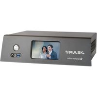
Pearl-2 - Processor Epiphan - Free user manual and instructions
Find the device manual for free Pearl-2 Epiphan in PDF.


| Product Type | All-in-one video capture, encoding, streaming, and recording appliance |
| Brand | Epiphan |
| Model | Pearl-2 |
| Dimensions | 12.2 x 9.4 x 1.7 inches (31 x 24 x 4.3 cm) |
| Weight | Approximately 5.5 lbs (2.5 kg) |
| Power Supply | Internal AC power supply, 100-240V, 50/60Hz |
| Power Consumption | Typical 60W, max 120W |
| Video Inputs | 4x 3G-SDI, 2x HDMI, 1x DVI-I (or VGA via adapter) |
| Video Outputs | 1x HDMI (program), 1x 3G-SDI (program), 1x HDMI (multiview) |
| Maximum Video Resolution | Up to 1080p60 per channel |
| Encoding | H.264, H.265, MPEG-2, MJPEG (selectable per channel) |
| Streaming Protocols | RTMP, RTSP, HLS, MPEG-TS, SRT, etc. |
| Recording | To internal SSD (optional), USB drives, or network storage |
| Audio Inputs | 2x XLR (balanced), 2x RCA (unbalanced), embedded HDMI/SDI |
| Audio Outputs | 1x 3.5mm headphone jack, embedded HDMI/SDI |
| Network | 2x Gigabit Ethernet (RJ45) |
| USB Ports | 2x USB 3.0 host, 1x USB 2.0 device |
| Internal Storage | Supports up to 2x SATA SSD (sold separately) |
| Control | Touchscreen, web interface, API, GPIO |
| Operating Temperature | 32°F to 104°F (0°C to 40°C) |
| Cooling | Internal fan (variable speed) |
| Maintenance | Keep vents clean; avoid liquids; use a dry cloth for cleaning |
| Safety | Operate in well-ventilated area; use only supplied power cord; no user-serviceable parts inside |
| Spare Parts & Repairability | Contact Epiphan support for replacement parts; device is not user-serviceable |
| General Information | Designed for live event production, lecture capture, and broadcasting |
Frequently Asked Questions - Pearl-2 Epiphan
User questions about Pearl-2 Epiphan
0 question about this device. Answer the ones you know or ask your own.
Ask a new question about this device
Download the instructions for your Processor in PDF format for free! Find your manual Pearl-2 - Epiphan and take your electronic device back in hand. On this page are published all the documents necessary for the use of your device. Pearl-2 by Epiphan.
USER MANUAL Pearl-2 Epiphan
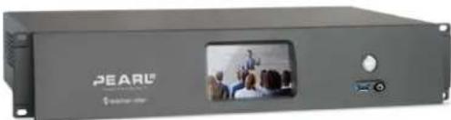
Epiphan Pearl-2 Pearl-2 Rackmount Pearl-2 Rackmount Twin

natural_image
Exterior view of a gray electronic device labeled 'PEARL' with a small screen showing a group photo (no readable text beyond branding)
natural_image
Exterior view of a modern audio equipment unit (no visible text or symbols)Terms and conditions
This document, the Epiphan web site, and the information contained therein, including but not limited to the text, videos and images as well as Epiphan System Inc.'s trademarks, trade names and logos are the property of Epiphan Systems Inc. and its affiliates and licensors, and are protected from unauthorized copying and dissemination by Canadian copyright law, United States copyright law, trademark law, international conventions and other intellectual property laws.
Epiphan, Epiphan Video, Epiphan Systems, Epiphan Systems Inc., and Epiphan logos are trademarks or registered trademarks of Epiphan Systems Inc., in certain countries. All Epiphan product names and logos are trademarks or registered trademarks of Epiphan. All other company and product names and logos may be trademarks or registered trademarks of their respective owners in certain countries.
Copyright © 2017 Epiphan Systems Inc. All Rights Reserved.
THE SOFTWARE LICENSE AND LIMITED WARRANTY FOR THE ACCOMPANYING PRODUCT ARE SET FORTH IN THE INFORMATION PACKET OR PRODUCT INSTALLATION SOFTWARE PACKAGE THAT SHIPPED WITH THE PRODUCT AND ARE INCORPORATED HEREIN BY REFERENCE. IF YOU ARE UNABLE TO LOCATE THE SOFTWARE LICENSES OR LIMITED WARRANTY, CONTACT YOUR EPIPHAN REPRESENTATIVE FOR A COPY.
PRODUCT DESCRIPTIONS AND SPECIFICATIONS REGARDING THE PRODUCTS IN THIS MANUAL ARE SUBJECT TO CHANGE WITHOUT NOTICE. EPIPHAN PERIODICALLY ADDS OR UPDATES THE INFORMATION AND DOCUMENTS ON ITS WEB SITE WITHOUT NOTICE. ALL STATEMENTS, INFORMATION AND RECOMMENDATIONS ARE BELIEVED TO BE ACCURATE AT TIME OF WRITING BUT ARE PRESENTED WITHOUT WARRANTY OF ANY KIND, EXPRESS OR IMPLIED. USERS MUST TAKE FULL RESPONSIBILITY FOR THEIR APPLICATION OF ANY PRODUCTS.
LIMITATION OF LIABILITY
UNDER NO CIRCUMSTANCES SHALL EPIPHAN BE LIABLE FOR ANY INCIDENTAL, SPECIAL, CONSEQUENTIAL, EXEMPLARY OR OTHER INDIRECT DAMAGES THAT RESULT FROM THE USE OF, OR THE INABILITY TO USE, THIS PRODUCT OR THE INFORMATION CONTAINED IN THIS DOCUMENT OR PROVIDED ON EPIPHAN'S WEB SITE, EVEN IF EPIPHAN HAS BEEN ADVISED OF THE POSSIBILITY OF SUCH DAMAGES. IN NO EVENT SHALL EPIPHAN'S TOTAL LIABILITY TO YOU FOR ALL DAMAGES, LOSSES, AND CAUSES OF ACTION RESULTING FROM YOUR USE OF THIS PRODUCT, WHETHER IN CONTRACT, TORT (INCLUDING, BUT NOT LIMITED TO, NEGLIGENCE) OR OTHERWISE, EXCEED THE AMOUNTS YOU PAID TO EPIPHAN DURING THE MOST RECENT THREE-MONTH PERIOD IN CONNECTION WITH AMOUNTS WHICH YOU PAID FOR USING THIS PRODUCT.
INFORMATION AND DOCUMENTS, INCLUDING PRODUCT SPECIFICATIONS, PROVIDED IN THIS DOCUMENT OR THE EPIPHAN WEB SITE ARE PROVIDED "AS IS". SPECIFICALLY, BUT NOT WITHOUT LIMITATION, EPIPHAN DOES NOT WARRANT THAT: (i) THE INFORMATION IS CORRECT, ACCURATE, RELIABLE OR COMPLETE; (ii) THE FUNCTIONS CONTAINED ON THE EPIPHAN WEB SITE WILL BE UNINTERRUPTED OR ERROR-FREE; (iii) DEFECTS WILL BE CORRECTED, OR (iv) THIS WEB SITE OR THE SERVER(S) THAT MAKES IT AVAILABLE ARE FREE OF VIRUSES OR OTHER HARMFUL COMPONENTS. EPIPHAN SPECIFICALLY DISCLAIMS ALL REPRESENTATIONS, WARRANTIES, AND CONDITIONS, EITHER EXPRESS, IMPLIED, STATUTORY, BY USAGE OF TRADE OR OTHERWISE INCLUDING BUT NOT LIMITED TO ANY IMPLIED WARRANTIES OF MERCHANTABILITY, NON-INFRINGEMENT, TITLE, SATISFACTORY QUALITY OR FITNESS FOR A PARTICULAR PURPOSE.
For additional terms and conditions, please refer to additional sections in this document.
Thank you for choosing Epiphan!
At Epiphan Video ("Epiphan"), product function and quality are our top priority. We make every effort to make sure that our products exceed your expectations.
Product feedback
Your feedback is important! We regularly contact our customers to ensure our products meet your performance and reliability requirements. We strive to continually enhance our products to accommodate your needs. Please let us know how you think we can improve our products by emailing your suggestions to info@epiphan.com.
Specifications
Go to the page of the Epiphan website to get the most recent product specifications and additional information about Epiphan Pearl-2.
Warranty
All Epiphan Systems products are provided with a 100% return to depot warranty for one year from the date of purchase.
Technical support
Epiphan's products are backed by our professional support team. If you are having issues with your product, please gather details about your system and contact our team by:
- Emailing support@epiphan.com
• Live chat via the link on our support site https://www.epiphan.com/support/
• Phone toll free at 1-877-599-6581 or call +1-613-599-6581
Be sure to include as much information about your problem as possible. Including:
- Problem description
• Details of the video or audio source (type, connection, resolution, refresh rate, etc.)
• Product serial number - Product firmware version (if applicable, from web admin interface)
Copyright © 2017 Epiphan Systems Inc. All Rights Reserved.
What's new in release 4.4.1?
Firmware 4.4.1 is a Pearl-2 maintenance release.
What's fixed
AV Synchronization
We improved the AV synchronization of an RTSP stream, which also improved synchronization when RTSP loopbacks are used. We also improved the AV synchronization and performance of 4K sources used on SDI and 4K HDMI ports.
Custom Wowza streaming option
You can use the custom streaming option again to stream to the Wowza Streaming Cloud instead of having to use an RTMP push.
AV.io SDI capture card recognition
Fixed an issue that caused Pearl-2 to sometimes not recognize an AV.io SDI capture card when it was first plugged in.
Hot plugged 1080i source recognition
Fixed an issue where interlaced 1080i signals from certain cameras (for example, Sony HDR-CX180, HDR-CX190, and Panasonic HC-VX980M) would not be detected when hot plugged in to an HDMI port on Pearl-2.
Table of contents
What's new in release 4.4.1? iv
Table of contents v....
Start here 1.
About this Guide 1
What is Pearl-2? 3....
Using Pearl-2 effectively 4.
AV inputs 4
What's in the Box? 5.
Front and back view 7
Pearl-2 8....
Pearl-2 Rackmount 10
Pearl-2 Rackmount Twin 12
Tech specs 14
About 4K on Pearl-2....17
Feature add-ons 17
Quick start 19
Get started quickly with auto channels: 19
To view the auto channels: 20
Record the Channel 21
What's Next? 22
Epiphan Live 23
Accessing Epiphan Live 24
Streaming, recording and monitoring using the Dashboard interface 26
Understanding the Dashboard interface 27
Configuring Dashboard panels for visual confidence monitoring 30
Monitoring video and audio sources 31
Configuring and monitoring video outputs 34
Controlling streaming and recording using Epiphan Live 37
Live switching using the Switcher interface 39
Understanding the Switcher interface 40
Switching while live streaming and recording 42
Your Recordings 45....
PART 1: Setup 48
Rackmount installation 49....
The Admin panel 50
Connect to the Admin panel 50
Connect using the touch screen 50....
Connect via DNS-based service discovery 51
Connect via the Epiphan discovery utility.53....
Connect via persistent static IP address 55
User administration 56
User types and privileges.... 56
Set or change user passwords.... 60
Remove user passwords 61
Overcome lost passwords 62
Configure LDAP 62
Change the logged-in user.... 64
Restrict viewers by IP address 65
IP restriction examples....67
Pearl-2's touch screen 70
Touchscreen overview 70
View system information 72
Channel monitoring.74
Individual channel monitoring....75
Grid-view channel monitoring....76
Pearl-2's audio jack 78
Control recording of individual channels.... 79
Control streaming of individual channels 81
One Touch streaming and recording control 82
Understand and use One Touch control 83
Specify channels and recorders for One Touch recording 85
Specify channels for One Touch streaming.89....
Customize how One Touch control is displayed 90
View AFU status 91
Configure the touch screen 94
Disable (or enable) the touch screen 94
Hide (or show) channel previews on the touch screen 95
Disable (or enable) system status on the touch screen 96.
Block (or allow) configuration functions from the touch screen 97
Block (or allow) recording, streaming and switching from the touch screen 97....
Set touch screen timeout 98
Configure touch screen PIN security code 99
View system information 101
Feature add-ons 102
Add-ons overview 102
Shop now 103
Install purchased add-ons 103
List of features 103
Purchase button 104
Activation indicator 104
Checking availability of add-ons 105
Available for purchase....105
Available for installation and activation 106
Available for use....107
Current list of add-ons 108
4K feature add-on 108
Activate purchased add-ons 109
Purchase and install add-ons 111
Configure network settings 115
Verify IP Address and MAC address via the touch screen.11.5....
Verify IP address and MAC address via the Admin panel.116....
Configure DHCP 117....
Configure a static IP address 119
Tether to a mobile network 1.23
Network ports used by Pearl-2 1.24
Perform network diagnostics.125....
Configuration presets 128....
Configuration presets overview 1.28
Configuration presets in action 129
Configuration groups.131....
Create a configuration preset 133
Export and import configuration presets 134
Download a configuration preset 134
Import a configuration preset.... 135
Apply a configuration preset from the Admin panel 136
Apply a configuration preset using the touch screen.... 137
Apply the Factory default configuration preset 141
Update a configuration preset.... 142
Delete a configuration preset 144
Configuration preset considerations 145
Channel and recorder index number behavior 145
Recording and streaming states 146
Recorded files (in channels and recorders) 146
Deleting channels 147
Branding content 147
Configuration presets are not user profiles.... 148
Touch screen considerations 148
Configure date and time 149
Verify date and time via the touch screen 149
Verify date and time settings 1.50
Configure synchronized time (NTP, PTP v1 and RDATE) 151
Configure the date and time manually.152....
Change the time zone 153
Configure a local NTP server 153
Video output ports 1.54
Show a channel on the video output port 155....
Show a source on the video output port 157
Select a resolution for the video output port 158....
Preview the video output port 159
View the video output port status.160....
Disable the video output port 161
Disable or enable the audio on the video output port 162
Configure the audio meter 163
Rename a video output port 164
PART 2: Capture 166
What is a channel? 167
Channels 168
Use the automatic channels Auto A and Auto B 168
Know which signal is used for Auto-A or Auto-B 169
Configure auto channels 170
Create a simple channel.... 171
Create a custom channel 176
Custom channel layout editor.... 177
Custom channel examples 181
Create a custom channel or layout.... 184
Add a video source (custom channel) 186
Add an audio source (custom channel).... 190
Custom crop a source 192
Configure chroma keying.... 194
To upload an image.214
Add an image (custom channel) 216
Add a text overlay (custom channel).220
Set the background color (custom channel) 227
Resize and position layout items using percents or pixels (custom channel) 227
Rename a layout (custom channel) 234
Delete, move, or duplicate a layout (custom channel).235.
Delete an uploaded image 237
Configure encoding.238
Configure video codec 238
Configure frame size 240....
Fine tune stream settings 242
Configure audio codec 244
Codec and file format compatibility 246
Multi-Encoding 246
Add channel metadata 249
Add channel metadata 249
Remove metadata from a channel 250
Preview a channel.... 250
Preview a channel from the Info page 251
Preview a channel from the Status page 251
Preview all channels at once 252
Rename a channel.... 253
Duplicate a channel 254
Delete a channel 254
Live video mixing / switching 256
Switching / mixing using the touch screen 256
Switching / mixing using the Admin panel 259
Switching / mixing using Epiphan Live 260
What is a source? 263
Video sources 263
Audio sources 264
Connect a source.265
Connect an RTSP source 266
Create an RTSP loopback 270
List of tested RTSP-based IP cameras 271
List of fully supported Web cameras 273......
Connect an AV.io video grabber 274
Preview a source.274
Configure a source.275
DVI and HDMI signals 276
SDI signals 277
USB signals 278
RTSP sources 281
Add a No Signal image to a source 281
Rename a source 282
Adjust audio gain (analog audio) and delay 283
Confirm audio levels 285
Troubleshoot capture 288
Remove black bars (matte) from the video 288
Match the output frame size to the aspect ratio of the source signal 289
Stretch the image 291
Force the capture card to use a specific EDID 291
Upload a new EDID 291
Restore factory default EDID 293
Unstretch the output video 294
Remove the combing effect on images 295
PART 3: Stream 297
What is streaming? 298
Choose a streaming option 298
Supported streaming formats, 299
Stream to viewers 300
Stream content using HTTP or RTSP.300....
Configure HTTP and RTSP streaming ports 302
Stream content using HLS (HTTP Live Streaming) 303
Send stream URLs to viewers 304
View the Flash stream.305
View your broadcast using the View link on the Info menu 305
View your broadcast using the Live broadcast link on the Status page 307....
Viewing with a web browser 309
Viewing with a media player (RTSP).310.
Disable (and enable) streams for viewers 311
Restrict access to streams for viewers 312....
Restrict viewers by IP address 313
IP restriction examples.... 315
Allow list with distinct IP addresses 315
Allow list with a range of IP addresses 315
Allow list with a range of IP addresses and one or more specific IP addresses 316
Deny list with distinct IP addresses 316
Allow list with a range of IP addresses, distinct IP addresses and an exception 317
Deny list with a range of IP addresses 317
Stream to a server 318
Stream to a CDN 319
Start and stop streaming to a CDN 320
To stream content to a CDN using RTSP announce 325
To stream content to a CDN using RTMP push 326
Stream to a CDN using an XML profile 328
Stream to Wowza Streaming Cloud 329
Stream to Original Livestream 332
Stream content using multicast 334
MPEG-TS streams using RTP/UDP push.334
MPEG-TS streams using UDP push 336
Multicast streaming using RTP/UDP 338
Viewing with Session Announcement Protocol (SAP) 339
Stream to a media player or smart TV 341
Stream content using UPnP.341
Enable UPnP 342
Disable UPnP 346
Viewing with UPnP 347
Play directly to a media player 348
Auto-restart playback to a UPnP device 348
Change UPnP device name 349
Samples of stream settings 350
Streaming video content 350
Streaming slide content 350
PART 4: Record 352
What is a recording? 353
Recording basics 353
Record a channel via the Admin panel 354
Record channels and recorders (using One Touch control) 356
Record a channel via Epiphan Live 358
Record a channel via the touch screen 359
Configure recording file size and type 361
Restart recording.... 364
Recorders 366
Add a recorder.... 366
Change the channels recorded by a recorder 367
Record with a recorder (using the admin panel) 368
Record a recorder (using One Touch control) 370
Record a recorder (using Epiphan Live) 371
Rename a recorder.372....
Duplicate a recorder 372
Delete a recorder.373....
Recorded files 375....
View list of recorded files 375....
Download recorded files manually 376
Concatenate files 377
Extract tracks from a recording 378
Rename recorded files 380
Delete recorded files manually 381
File and recording transfer 383
Automatic file upload (AFU) overview 383
Choose files to include in AFU 384
Enable AFU and set parameters 386
AFU to an FTP server 389
AFU using RSync 391
AFU using CIFS 392
AFU using SCP 394
AFU to a secure FTP server.... 396
AFU to Amazon Web Server (AWS) 398
AFU to a WebDav server 399
AFU or copy to USB 400
AFU to a USB drive 401
One-time copy/move of all recorded files to USB drive 402
Manually copy recorded files to USB drive 404
View available USB storage space 406
Safely eject the USB drive.... 406
View the AFU log 407
View AFU status 408
Manage the AFU queue 410
Access the AFU queue 410....
View content in the AFU queue 411
Delete content in the AFU queue.412
Local FTP server 413....
Configure the local FTP server 413
Using the local FTP server 415
PART 5: Maintenance 417....
Power down and system restart 4.1.8
Restarting the device via the Admin panel 418
Shutting down the device via the Admin panel 418....
Shutting down the device manually 419
Save and restore device configuration 420
Perform factory reset 42.1
Restore factory configuration via the Admin panel 421
Firmware upgrade 423
Check for firmware updates 423
Install firmware 424
Install firmware directly from the Admin panel: 424
Install firmware from a file 426
Support 428
Download logs and "allinfo" 428
Configure remote support.... 430
Disable remote support 431
Storage disk maintenance 432
Check disk storage space 432
Check disk storage space via the touch screen 433
Schedule disk check 433
Perform disk check.... 434
Third party integration 436
Control with RS-232 / serial port 437
Connect and configure the RS-232 cable 437
Control Pearl-2 with RS-232.438....
RS-232 / Serial port command examples 441
Control with HTTP commands 443
HTTP command syntax 443
HTTP command examples 445
Global variable HTTP command syntax for custom layouts 446
Configuration keys for third party APIs.449....
System-level settings keys (read-only) 450
System-level settings keys (read/write) 450
System-level custom layout keys (read/write) 451
Touch screen settings keys (read/write).451....
Recording configuration keys 452
HTTP server configuration keys 453
IP-based access control configuration keys 453
UPnP configuration keys 454
Broadcast configuration keys 454
Channel encoder configuration keys 455
Channel layout configuration keys 456
Audio configuration keys.... 457
Stream publishing configuration keys 457
RTSP Announce configuration keys (Publish type 2) 458
RTP/UDP configuration keys (Publish type 3) 459
MPEG-TS configuration keys (Publish types 4 and 5).... 459
RTMP push configuration keys (Publish type 6 and 7) 460
Livestream configuration keys (Publish type 8) 460
Content metadata configuration keys 460
PART 6: Troubleshooting ....462
Limitations and known issues 467
Previous releases and features 471
Software license 473
Start here
Welcome, and thank you for buying Epiphan Pearl-2™. This guide is designed to help you configure your new system.
Pearl-2 details (for all three models) are described in the What is Pearl-2? and What's in the Box? sections. Read the Quick start guide for the basic steps to get a single video (and optional audio) source configured as a streamable, recordable output from Pearl-2.
Following the quick start section, a set of task-based procedures help you to tweak the system exactly how you want it. These procedures are broken into five categories: Setup, Capture, Stream, Record and Maintenance.

Setup

Capture

Stream

Record

Maintenance
About this Guide
Throughout this guide there are situations where more than one solution will complete a task. In those cases the guide describes the simplest or most common variation first. Warnings, tips and notes are depicted as follows.

This is a warning. Pay special attention to information in red boxes.

This is a tip or note. Data in green boxes help you get the most from your new system.
Feature add-on notes: This user guide provides general instructions for the functionality of Pearl-2 with the assumption that all add-ons are activated. Throughout the manual, in cases where there is a function or option that is only available after a particular add-on is activated, it is indicated by a link to the Feature add-on activation instruction page. For the 4K add-on, the link is: ^4K .
What is Pearl-2?
Pearl-2, our most versatile live video production device, is a video encoder, video streamer, live switcher and video recorder that comes in three models.
All three models have the same functionality, and this guide applies for all three models. Where used in this guide, the product name Pearl-2 is interchangeable for Pearl-2 Rackmount or Pearl-2 Rackmount Twin, except in a few cases where physical differences are explicitly called out.
Pearl-2
A small, silent, portable system that comes with a hard-shell carry case.
Pearl-2 Rackmount
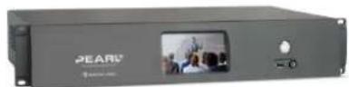
A 2U rackmount server with all the same functionality as the portable Pearl-2, but designed for installation and operation in a rack.
Pearl-2 Rackmount Twin

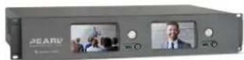
A high density 2U rack mount variation that contains two complete (and independent) Pearl-2 systems.
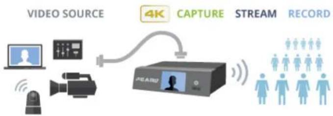
With Pearl-2, you can capture, record and stream computer monitors, radar displays, or almost anything that outputs to SDI, HDMI™, USB, HDMI 4K ^4K or DVI-I (single link). Capture audio from XLR, RCA, USB, SDI or HDMI sources.
Simultaneously capture up to six full HD video sources or up to four 4K sources if you have the 4K feature add on installed. You can create up to five simultaneous channels for live switching, or a single 4K channel.
View streams using media players, browsers, on mobile devices or using Content Distribution Networks (CDNs). Recorded files can be downloaded using FTP or set to automatically upload using FTP, RSYNC, or CIFS and can be integrated into your Content Management System (CMS).
flowchart
graph LR
    A["VIDEO SOURCE"] --> B["4K CAPTURE"]
    B --> C["STREAM"]
    C --> D["RECORD"]
    A --> E["IMAGE"]
    E --> F["Monitor"]
    F --> G["Camera"]
    G --> H["Wireless Signal"]
    H --> I["User icon"]
    style A fill:#f9f,stroke:#333
    style B fill:#ccf,stroke:#333
    style C fill:#cfc,stroke:#333
    style D fill:#fcc,stroke:#333
    style E fill:#ffc,stroke:#333
    style F fill:#cfc,stroke:#333
    style G fill:#fcc,stroke:#333
    style H fill:#ffc,stroke:#333
    style I fill:#fcc,stroke:#333

Pearl-2 does not capture from HDCP encrypted sources.
Using Pearl-2 effectively
Pearl-2, Pearl-2 Rackmount and Pearl-2 Rackmount Twin are powerful live video production systems. They can perform many different tasks, however, like any other computer system, there is a limit to the number of concurrent tasks that can be processed and run smoothly.
For best results, we recommend you always keep the CPU usage on Pearl-2 under 70%. You can check the Overall system load from the Info page.
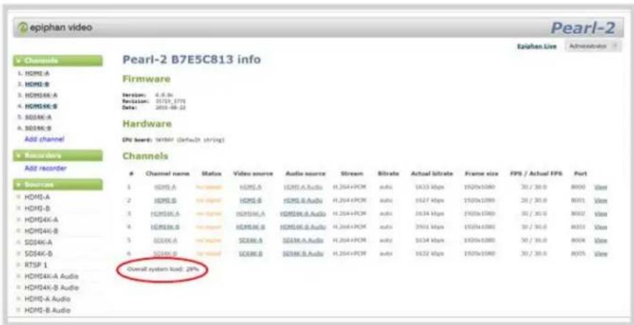
The actual number of tasks your Pearl-2 can complete concurrently depends on many factors, including: how many channels you have, how many layouts you have per channel, how often you are switching layouts, whether or not the system is resizing input signals, frame rate and bit rate per channel, whether or not you are using the video output ports, etc.
If you find that system load is higher than recommended, try to: disable any unused video output ports, delete unused channels or layouts, reduce the number of channels created or ensure sources come in at the right resolution to avoid CPU time spent scaling.
AV inputs
Pearl-2 supports the following AV inputs directly. Nearly every other AV input is supported provided you have the correct converter or adapter.

When using Pearl-2 we recommend having a maximum of six 1080p sources in up to 6 full HD channels or having up to four 4K sources in a single channel for best results.
Table 1 Inputs for Pearl-2*
| SDI Audio (Linear PCM) | HDMI ^TM (Linear PMC, non-HDCP protected)/DVI-I (single link) | 4K HDMI ^1 (Linear PMC, non-HDCP protected)/DVI-I (single link) | USB (Linear PMC, non-HDCP protected) | Left/Right XLR Audio (Balanced) | Left/Right RCA Audio (Balanced) |
| 2 2 2 | 2 2 1 |
^1 Requires 4K feature add on
Note: Pearl-2 cannot simultaneously use both XLR audio input pairs along with the RCA audio pair. Use the left-most XLR pair when using the RCA pair.
*Pearl-2 Rackmount Twin has two complete sets of these inputs.
What's in the Box?
There are three models of Pearl-2, namely the original portable model, and two rackmount models, Pearl-2 Rackmount and Pearl-2 Rackmount Twin.
Pearl-2

Pearl-2 Rackmount
Pearl-2 Rackmount Twin
Pearl-2 is shipped in a hard shell case that you can re-use for storing or moving the system between jobs. Cable storage is under the custom foam tray that holds Pearl-2 in the case.

natural_image
Exterior view of a PEARL 3000 smart air conditioner unit and its internal display case (no signage or text on device)Inside the box with your Pearl-2 system, you'll find the power cable and the following items, and for Pearl-2 Rackmount Twin you'll receive two sets of these cables:
- One SDI cable (3 feet / 1 meter in length)
- One HDMI cable (3 feet / 1 meter in length)
- One HDMI to DVI adapter
- One Ethernet cable
- One region-specific power supply cable (6 feet / 1.8 meters in lengths)
The following table will help you identify the cables included with your Pearl-2 purchase. Note these images are for identification purpose only. The cables included with your purchase are not proprietary. If desired, you can use other separately purchased cables to capture your sources.
Table 2 Description of included cables (images for identification only, color and appearance may vary)
| Image Name Description | ||
 | SDI cable | Connects SDI sources to Pearl-2's SDI ports (12G-SDI capable). Roughly 3 feet (or 1 meter) in length. |
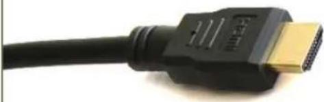  | HDMI cableDVI (female) to HDMI (male) adapter | Connects HDMI or DVI sources to Pearl-2's HDMI ports. Roughly 3 feet (or 1 meter) in length.Connects DVI sources to Pearl-2. Connect the adapter to the output on your screen or device, then connect the provided HDMI cable to the adapter and one of the HDMI ports on Pearl-2's back panel. |
 | RJ-45 Ethernet cable | Connects the system to your network. |
Front and back view
Pearl-2's front panel has the power button and indicator light, audio monitor jack, USB 3.0 port and touch screen display for confidence monitoring and simple configuration. There are connectors on the back of the unit to connect your video sources, audio, and other devices like external monitors to Pearl-2. See below for a complete listing of Pearl-2's physical features.

The SDI ports on the back of Pearl-2 can be delicate. Be careful to avoid sharp impacts or pressure such as balancing the system on its back with the SDI ports against a hard surface. Rough treatment of the SDI ports could result in loss of functionality for that port.
Pearl-2
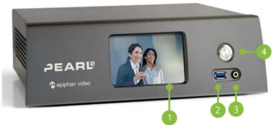
Table 3 Pearl-2 front panel descriptions
| Label | Name Description | |
 | Touch screen front panel display | Used for confidence monitoring and simple configuration such as obtaining system information, previewing streams, changing publishing option and starting/stopping recordings. |
 | USB 3.0 port | For connection of external hard drives, flash drives or control interfaces. See AFU or copy to USB for copying data to a USB drive. Web cameras cannot be connected to this port, only the ports on the rear. |
 | 3.5 mm audio jack | For audio confidence monitoring. Plays the audio for the currently visible channel. |
 | Power button Press to turn | on. Double-click to initiate a graceful system shutdown. |
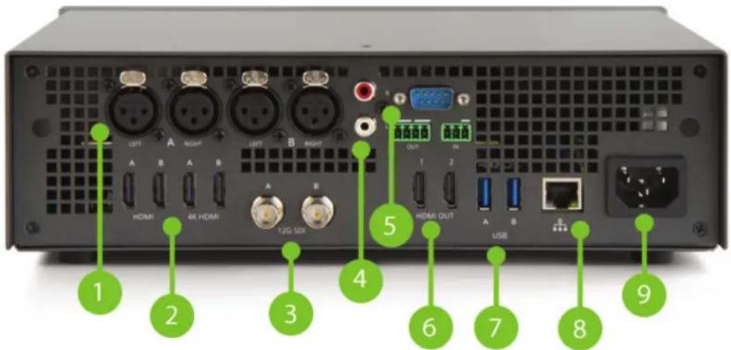
Table 4 Pearl-2 back panel descriptions
| Label | Name Description | |
 | XLR ports | The four ports connect up to two line level left/right XLR audio signal pairs to Pearl-2, calibrated for a signal of + 4.0 dBu. |
 | HDMI in | Four HDMI 1.4 ports that connect HDMI and DVI signals to Pearl-2. The first two ports allow for any signal up to full HD, and the second two inputs allow for any input resolution up to 4K . |
 | 12G SDI in | Connects SDI signals to Pearl-2, including 3G-SDI; 6G-SDI; 12G-SDI; 4K-SDI; HD-SDI; SD-SDI |
 | RCA audio in | Connects line level left/right RCA audio to Pearl-2, calibrated for a signal of - 10.0 dBV. |
| [XDB4] | RS-232 port For connection to a control computer terminal. | |
 | HDMI output ports | HDMI output for connection to a display or projector (up to 4K). Port 1 is HDMI 2.0, and Port 2 is HDMI 1.4. See Video output ports for more details. |
 | USB 3.0 ports | For connection of external hard drives, flash drives, USB webcameras USB microphones or control interfaces. See AFU or copy to USB for copying data to a USB drive. |
 | ||
 | RJ-45 Ethernet | Auto-sensing gigabit Ethernet 10/100/1000 Base-T network port. See Configure network settings for setup instructions. |
| 9 | Power jack | Plug the power supply in here. Always use the provided 120/240 V power supply. |
^1 Requires 4K feature add on
Pearl-2 Rackmount
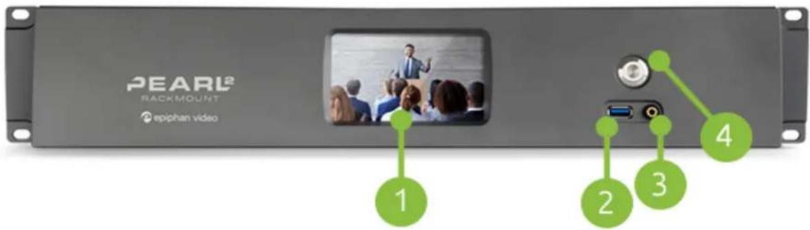
Table 5 Pearl-2 Rackmount front panel descriptions
| Label | Name Description | |
 | Touch screen front panel display | Used for confidence monitoring and simple configuration such as obtaining system information, previewing streams, changing publishing option and starting/stopping recordings. |
 | USB 3.0 port | Two other USB ports are located on the back. See Record for information about recording to USB drives. Web cameras cannot be connected to this port, only the ports on the rear. |
 | 3.5 mm audio jack | For audio confidence monitoring. Plays the audio for the currently visible channel. |
 | Power button and LED | Press to turn on.Double-click to initiate a graceful system shutdown. |
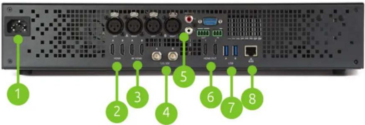
Table 6 Pearl-2 Rackmount back panel descriptions
| Label | Name Description | |
| 1 | Power jack Plug the power supply in here. Always use the provided power supply. | |
| 2 | HDMI in Connects HDMI and DVI signals to Pearl-2 Rackmount. | |
| 3 | 4K HDMI in Connect up to 4K ^1 HDMI signals to Pearl-2 Rackmount. | |
| 4 | SDI in Connects SDI signals to Pearl-2 Rackmount. | |
| 5 | XLR Audio (two pairs), RCA pair | Connects line level left/right XLR audio and/or RCA audio to Pearl-2 Rackmount. |
| 6 | HDMI Out For displaying a source or channel on an external display (up to 4K ^1 ). | |
| 7 | USB 3.0 ports | For connection of external hard drives, flash drives, USB webcameras USB microphones or control interfaces. See Record for recording to a USB drive. |
| 8 | RJ-45 Ethernet | Auto-sensing gigabit Ethernet 10/100/1000 Base-T network port. See Configure network settings for setup instructions. |
^1 Requires 4K feature add on
Pearl-2 Rackmount Twin
This model is comprised of two completely independent Pearl-2 systems. The diagrams below show callouts and labels for one of the two systems, the second (on the right side of the images) has all the same features.

Table 7 Pearl-2 Rackmount Twin front panel descriptions
| Label | Name Description | |
 | Touch screen front panel display | Used for confidence monitoring and simple configuration such as obtaining system information, previewing streams, changing publishing option and starting/stopping recordings. |
 | USB 3.0 port | Two other USB 3.0 ports are located on the back. See Record for information about recording to USB drives.Web cameras cannot be connected to this port, only the ports on the rear. |
 | 3.5 mm audio jack | For audio confidence monitoring. Plays the audio for the currently visible channel. |
 | Power button and LED | Press to turn on.Double-click to initiate a graceful system shutdown. |

Table 8 Pearl-2 Rackmount Twin back panel descriptions
| Label | Name Description | |
| 1 | Power jack Plug the power supply in here. Always use the provided power supply. | |
| 2 | HDMI in Connects HDMI and DVI signals to Pearl-2 Rackmount. | |
| 3 | 4K HDMI in Connects up to 4K ^1 HDMI signals to Pearl-2 Rackmount. | |
| 4 | SDI in Connects SDI signals to Pearl-2 Rackmount. | |
| 5 | XLR Audio (two pairs), RCA audio | Connects line level left/right XLR audio and/or RCA audio to Pearl-2 Rackmount. |
| 6 | HDMI Out For displaying a source or channel on an external display (up to 4K). | |
| 7 | USB 3.0 ports | For connection of external hard drives, flash drives, USB webcameras USB microphones or control interfaces. See Record for recording to a USB drive. |
| 8 | RJ-45 Ethernet | Auto-sensing gigabit Ethernet 10/100/1000 Base-T network port. See Configure network settings for setup instructions. |
^1 Requires 4K feature add on
Tech specs
This table outlines the technical specifications for Pearl-2. Go to www.epiphan.com/pearl-2 to get the most recent product specifications and additional information about Pearl-2.

The table below shows the number of inputs and output connectors for Pearl-2 and its rackmount versions. The Pearl-2 Rackmount Twin version comprises two completely independent Pearl-2 systems, therefore has double the number of every input, output and component that Pearl-2 and Pearl-2 Rackmount have.
Table 9 Specifications for Pearl-2
| Video Inputs | Connectors | (2) 12G SDI(2) HDMI^TM / DVI^1 (2) 4K HDMI^2 / DVI^1 (2) USB video | ||
| Resolutions | Most common and custom HDMI/DVI/SDI/USB modes up to 4096×2160 | |||
| Video Format Options | 3G-SDI; 6G-SDI; 12G-SDI; 4K-SDI; HD-SDI; SD-SDI DVI single link (through an adapter), USB video through USB Webcam or UVC AV.io video grabber; HDMI , 4K HDMI^2 | |||
| Audio Input | Connectors (balanced or unbalanced signals) | (2) Stereo XLR (Pro line level, no phantom power output, + 4.0 dBu)(1) Stereo RCA (Consumer line level, - 10.0 dBV)(2) SDI audio(4) HDMI audio(2) USB audio | ||
| Analog audio sensitivity | XLR Max signal: 12.3 V (RMS), (+24 dBu)RCA signal level: - 10.0 dBV | |||
| Video Output | Connectors | (2) HDMI out with audio for local video display or larger confidence monitoring | ||
| Built-In Display | Front touch screen display used for system information, | |||
| confidence monitoring, simple configuration and recording control | ||||
| Audio Output 3.5 mm audio Front-mounted jack for confidence monitoring | ||||
| Video Encoding | Video Codecs H.264, | Motion JPEG | ||
| Video Bit Rates 1 - 50 | Mb/s | |||
| Key Frame Intervals Programmable | ||||
| Color Resolution 4:2:0 | ||||
| Output Frame Size Configurable up to 4096×2160 | ||||
| Audio Encoding Audio Codecs | Encoder | Bitrate Sample | Frequencies | |
| MP3 | 64-320 kbps | 22 kHz, 44 kHz, 48 kHz | ||
| PCM | - | 22 kHz, 44 kHz, 48 kHz | ||
| AAC | 64-320 kbps | 16 kHz, 22 kHz, 44 kHz, 48 kHz | ||
| IP Network Interfaces | Connector | (1) 10/100/1000 Ethernet RJ45 | ||
| Streams | MPEG-TS, and FLV | |||
| RTSP over TCP/UDP | ||||
| Multi-Publish to Streaming Server / CDN (RTSP, RTMP) | ||||
| HLS - Native Apple HTTP stream for iPad, iPhone and iPod Touch | ||||
| Multicast Streams | RTP, MPEG-TS & RTP and MPEG-TS over UDP | |||
| Network Discovery / Announce | UPnP, SAP | |||
| Video / Audio Recording and File Management | Internal Storage^2 | 512 GB SSD | ||
| Automatically removes oldest recordings from internal storage as space is required. | ||||
| File maintenance through admin interface (Web UI) | ||||
| Local Storage | Automatic or manual copy to local USB drives via the (3) USB 3.0 ports | |||
| Network Storage | FTP server and FTP client capabilities (automatic and manual) | |||
| Playback and Recorded Formats | Download recorded videos (AVI, MOV, MP4 or MPEG-TS) using the Web UI and playback through any compatible player. | |||
| Administration | Web UI for full administration. On-screen display and mobile UI for confidence monitoring and simple administration and control. | |||
| Multiple user accounts/passwords. | ||||
| Included API for integration into existing environments (executed via HTTP or RS-232). | ||||
| Time Synchronization NTP, TIME (RFC 868), PTP v1 (IEEE-1588-2002 V1) | ||||
| Power use 0.8 A, 100-240 V ac | ||||
| Product Dimensions | Pearl-2: 11.81" × 9.45" × 3.54" (300mm x 240mm x 90mm)Pearl-2 Rackmount: Pearl-2 Rackmount TwinPearl-2 Rackmount Twin: 19 1/8" x 31⁄2" x 10 7/8" (498 mm x 89 mm x 276 mm) | |||
| Product Weight | Pearl-2: 8.38 lbs (3.8 kg)Pearl-2 Rackmount: 12.1 lbs (5.5 kg)Pearl-2 Rackmount Twin: 14.6 lbs (6.6 kg) | |||
| Country of Origin Made in Taiwan | ||||
^1 Using HDMI port, with adapter
^2 Requires 4K feature add on
^3 A portion of the hard drive space (approximately 100 MB) is reserved for system use. Recording space can be virtually unlimited with offload to networked storage.
About 4K on Pearl-2
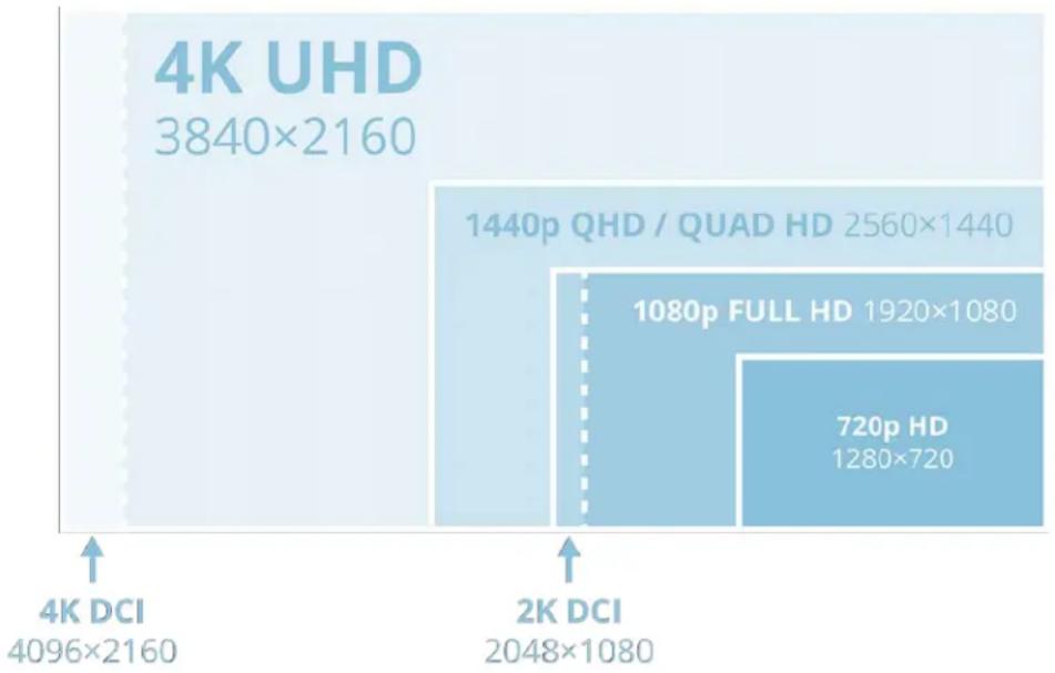
Pearl-2 supports resolutions from low-res SD to 4K, which means that you can use Pearl-2 to capture both DCI 4K and 4K UHD digital signals.
DCI 4K and 4K UHD are just different definitions of a 4K resolution. 4K UHD (3840×2160) is the standard 4K resolution available on televisions and other common display screens. The 4K resolution of 4096×2160 is referred to as Digital Cinema Initiatives (DCI) 4K, and is the resolution used almost exclusively for cinema-scale film production. It is rare to find this resolution outside of a cinematic context. Pearl-2 is capable of supporting input and output at either definition with the Feature add-ons.
bar_stacked
| Category | Value (p) | |---|---| | 4K UHD | 3840×2160 | | 2K DCI | 2048×1080 | | 1440p QHD / QUAD HD | 2560×1440 | | 1080p FULL HD | 1920×1080 | | 720p HD | 1280×720 |Feature add-ons
Pearl-2 hardware provides many useful new features and with more to come. From the common base model of Pearl-2, you can add feature add-ons for extra functionality.
For an overview of add-ons, see:
- Add-ons overview
This section also covers the following related topics:
- Checking availability of add-ons
• Current list of add-ons
• Activate purchased add-ons
• Purchase and install add-ons

Throughout the manual, there is information that applies only when your system has the 4K feature add-on, as indicated with this symbol: . Wherever that symbol appears, it denotes that the feature is available only if you have activated the 4K feature add-on for your Pearl-2.
Quick start
This section helps you get up and running quickly with your Pearl-2. The instructions are the same regardless of the model you are using. If using a rackmount model, you can choose to have it already installed in a rack, or it can be placed on a desk.
Before you get started, make sure you have:
- a video source (i.e. a camera, a computer, a tablet, or a phone). For HDMI, the source must not be HDCP protected.
- for SDI, USB video or HDMI sources, accompanying audio over the same source cable, or optionally audio from a XLR or RCA source
- the appropriate cables or adapters to convert the output to SDI or HDMI (if needed)
- ideally, a network with Dynamic Host Configuration Protocol (DHCP)
- a computer with a web browser connected to the same network (this is referred to as the "admin" computer in the steps below)
Pearl-2 is pre-configured with two plug and play channels: Auto A and Auto B. This quick start uses these channels to get you streaming and recording as soon as possible.

If you're using a Pearl-2 Rackmount Twin, be sure to follow all the steps below using one of the two systems (i.e. you cannot plug a source into one system and use it from the other).
Get started quickly with auto channels:
- Turn on your video source and connect the output cable to a port labeled "A" on the back of Pearl-2 (if needed, use an adapter such as the DVI to HDMI adapter).
- If desired, plug a second source into one of the "B" inputs on the back of the system.
- Optionally, attach a set of left/right XLR or RCA audio cables from your audio source to the XLR or RCA audio input ports on the back of Pearl-2.
- Connect the Ethernet cable to the Pearl-2. Connect the Ethernet cable to your network.
- Attach the power cable to the system and plug it into a power source.
- Use the power button to turn on the system.
- Wait for Pearl-2 to complete the power-up sequence. The system is ready a few moments after the power LED illuminates.
- (optional) Plug speakers or headphones into the 3.5 mm audio jack at the front of Pearl-2 for confidence monitoring.
The system automatically configures the channel's frame size to match the source resolution and calculates the best bit rate for the default frame rate of 30 fps. Audio could come from any of the SDI, HDMI, USB video, XLR or RCA audio inputs (SDI or HDMI audio must be unencrypted).
Pearl-2's front screen, if enabled (it is enabled by default, see Configure the touch screen), updates to show you previews of your channel(s) for confidence monitoring. Use your speakers or headphones to verify audio quality and levels.

To view the auto channels:
You can start viewing the channel(s) immediately by using a browser on a computer on the same network.
- Find the system's IP address: from a single channel view or grid view, touch the system settings (gear) button then touch System Status.
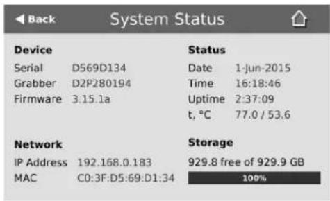
- Open a browser window on a computer on the same LAN or network
- Browse to one of the following URLs:
For Auto A: http://
For Auto B: http://
For example: http://192.168.0.183/preview.cgi?channel=2
You'll find alternate connection streams (i.e. RTSP or MPEG-TS) for these channels by logging into the Admin panel and accessing Auto A and Auto B by the links under the Channels menu. See What is streaming?
Record the Channel
The channel is set up and streaming. This may be all you need, but if you like, you can also record the stream. You can choose to initiate and control channel recording from either the touch screen or the Admin panel.
To control recording from the touch screen:
-
If viewing the grid view, touch the channel for which you wish to control recording; the channel view is displayed.
-
If the channel controls are not displayed on the screen, simply touch the screen to bring them up.
-
Touch the recording control button; the touch screen will start a timer to indicate the length of the recording. Touch the control again to stop recording. (If the button is not visible, recording control via the touch screen is not enabled; see Configure the touch screen.)

To control recording from the Admin panel:
-
From the Admin panel, scroll to the Channels section.
-
Click Recording for your channel; the Recording page is displayed.
-
Click the red Start button; the text at the top of the screen changes to indicate the recording is starting, then indicates the length of time since the recording started.
-
Click the black Stop button; the recorder stops.
-
Refresh the page by clicking Recording again; the page reloads and a file list appears that shows your newly recorded stream snippet.
-
Click the file name to download and view your recording.
What's Next?
Now that you have a source setup and ready to stream, you can fine-tune the system to your exact requirements. You can look at topics such as:
• Create a simple channel
• Create a custom channel
• Video output ports
- Add an audio source (custom channel)
• Live video mixing / switching
• What is streaming?
- File and recording transfer
- User administration
When you have completed system tuning, make sure to back up the system configuration using the procedure described in:
• Create a configuration preset
Refer to the table of contents for a complete list of the topics covered.
Epiphan Live
Epiphan Live is a friendly and easy to use web and tablet interface designed for users with administrator and operator-level privileges. (See User administration for more information on setting user privileges). The Epiphan Live interface allows users to perform basic operation of their Pearl-2, including:
• streaming and recording control for channels and recorders
• live switching between sources and custom layouts while streaming and recording
• video, audio and system confidence monitoring
EPIPHAN LIVE
Epiphan Live is supported on the following operating systems/mobile devices and web browsers:
| Operating system or mobile device | Supported web browser(s) |
| Windows | Google ChromeMicrosoft Edge |
| Mac | Google ChromeSafari |
| Linux • Google Chrome | |
| Android phone or tablet | Google Chrome |
| iPhone or iPad | Google ChromeSafari |

Text scaling using Google Chrome for Android is not supported.
Topics in this section include:
- Accessing Epiphan Live
• Streaming, recording and monitoring using the Dashboard interface
• Live switching using the Switcher interface
Accessing Epiphan Live
You can access Epiphan Live directly using your web browser, mobile device or by clicking a link within the Admin panel. You can also use Epiphan Live to access the Admin panel.
Before connecting to Epiphan Live, you need to know your Pearl-2's IP address. If you don't know your Pearl-2's IP address or are setting up for the first time, see Connect to the Admin panel to get your IP.
Connecting to Epiphan Live directly using your computer's web browser
You can connect to Epiphan Live directly using a web browser on your Windows, Mac or Linux computer.
To connect to Epiphan Live using your web browser:
- Enter the following information into the address bar of your web browser, using the syntax below:
http://
- Enter your administrator or operator credentials when prompted; you are now connected to Epiphan Live.

If you're using the Chrome browser on an HTTPS network and your website has an insecure or invalid security certificate, you can't preview any channels using the Dashboard even after updating the security certificate in Chrome. Use a different web browser instead, such as Firefox, and add the security certificate for the website to the exceptions list.
Connecting to Epiphan Live directly using your mobile device
You can connect to Epiphan Live directly using your Android phone/tablet, iPhone or iPad.
To connect to Epiphan Live directly using your mobile device:
- Enter the following information into the address bar of your web browser, using the syntax below:
http://
- Enter your administrator or operator credentials when prompted; you are now connected to Epiphan Live.
Connecting to Epiphan Live from the Admin panel
Accessing Epiphan Live from the Admin panel requires you to first connect to the Admin panel.
To connect to Epiphan Live from the Admin panel:
- Enter the following information into the address bar of your web browser, using the syntax below:
http://
-
Enter your administrator or operator credentials when prompted to connect to the Admin panel.
-
Click Epiphan Live in the upper-right corner of the window; the Epiphan Live dashboard opens in a new window or tab.

Connecting to the Admin panel from Epiphan Live
You can also use Epiphan Live to connect to the Admin panel.
To connect to the Admin panel from Epiphan Live, click the Menu icon in the upper-right corner of the Dashboard or Switcher interface and then click Admin panel.

Streaming, recording and monitoring using the Dashboard interface
The Epiphan Live Dashboard view is an easy-to-use interface that allows you to control the streaming and recording of channels and also to monitor your video inputs, video outputs, audio inputs and system information.
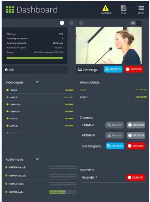
Topics in this section include:
• Understanding the Dashboard interface
- Configuring Dashboard panels for visual confidence monitoring
• Monitoring video and audio sources
- Configuring and monitoring video outputs
• Controlling streaming and recording using Epiphan Live
Understanding the Dashboard interface
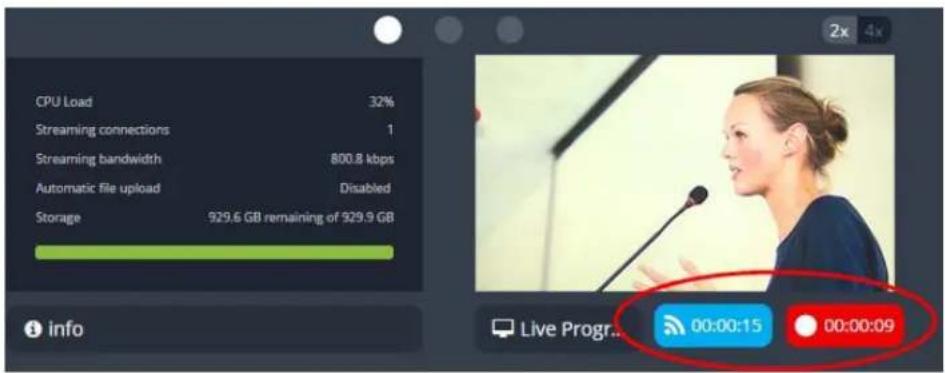
You are first presented with the Dashboard interface upon logging in to Epiphan Live. The Dashboard interface contains many helpful elements used for confidence monitoring and streaming/recording control, described in the Elements in the Dashboard interface table below.

The Dashboard view is responsive and automatically adjusts and repositions its elements to fit cleanly within any size web browser window.
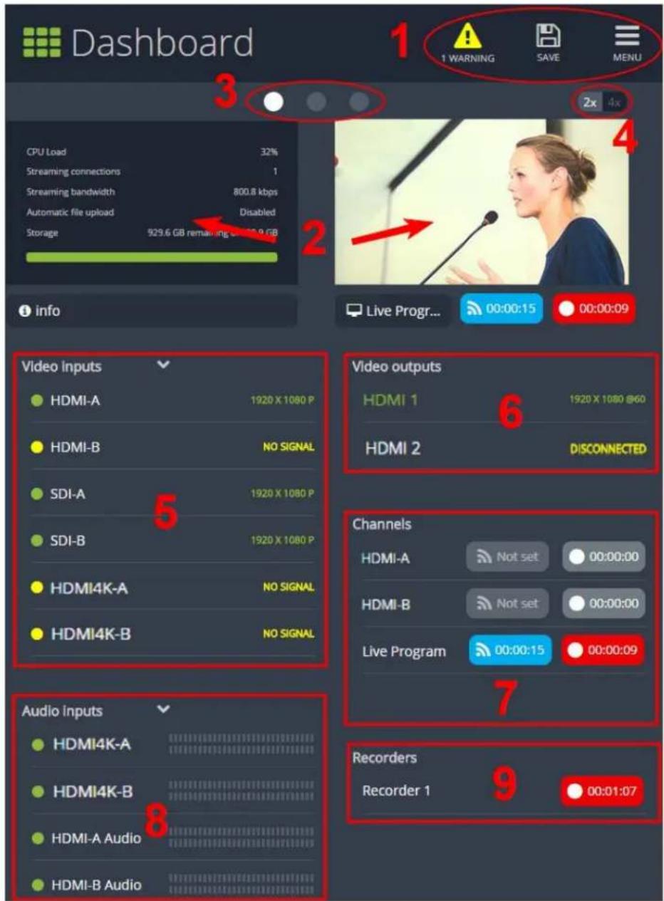
Table 10 Elements in the Dashboard interface
| Number Title Description | ||
| 1 | Dashboard header icons | Warning – This icon displays only if there are any configuration errors in your channels, sources, streams or recordings. Clicking the icon displays more detail about the errors. |
| Number | Title Description | |
Save-Saves any Dashboard layout changes. Note that you need to press Save to preserve your layout setting. When a layout is saved, all other operators and administrators will see your configured Dashboard layout when they log in or refresh their Epiphan Live page.Menu-When clicked, displays links to the Switcher view, Recordings, and Admin panel. Note that you need to press Save to preserve your layout setting. When a layout is saved, all other operators and administrators will see your configured Dashboard layout when they log in or refresh their Epiphan Live page.Menu-When clicked, displays links to the Switcher view, Recordings, and Admin panel. | ||
| 2 | Dashboard monitoring panels | Configurable panels used for confidence monitoring. You can set each panel to display a source, channel, output or basic system information. Note that the Dashboard monitoring panels appears blank by default when logging in for the first time. |
| 3 | Dashboard panel navigation icons | Click to navigate between three different sets of Dashboard monitoring panels. The illuminated icon represents your currently displayed panel set. |
| 4 | Dashboard panel set quantity icons | 2x-Changes the quantity of Dashboard panels per set to 2 (as in the screen shot above).4x-Changes the quantity of Dashboard panels per set to 4. |
| 5 | Video inputs | Displays a list of your video inputs configured in the Admin panel and includes basic status information for each input. |
| 6 | Video outputs | Displays a list of your video output ports configured in the Admin panel and includes basic status information for each output. |
| 7 | Channels | Displays a list of your channels configured in the Admin panel and includes streaming and recording control buttons for each channel, as well as individual control buttons for each stream when you set up multiple streams in a channel. |
| 8 | Audio inputs | Displays a list of your audio inputs configured in the Admin panel. Includes basic status information and a VU meter for each input. |
| 9 | Recorders | Displays a list of your recorders configured in the Admin panel and includes a recording control button for each recorder. |
Configuring Dashboard panels for visual confidence monitoring
You can customize each Dashboard panel to display a specific channel, source or video output. Epiphan Live allows you to configure up to 8 different panels for comprehensive live preview confidence monitoring of channels and sources. Note that when Dashboard panels are configured, other users idle on the Dashboard interface must refresh the page in their web browser to display the updated panels.

The limit of 8 live preview panels applies across all other open instances of Epiphan Live. Additional users may access Epiphan Live simultaneously from separate locations, for example, or an operator may accidentally open a duplicate Epiphan Live interface.
You can also display the following set of basic system information in your panels:
- CPU load (%).
• Quantity of streaming connections.
• The current streaming bandwidth (bitrate).
• Storage available on your Pearl-2.
• Automatic file upload status (enabled or disabled). See File and recording transfer.
To configure your Dashboard panels:
- Log in to Epiphan Live (see Accessing Epiphan Live).
- Click the drop down box under your desired panel (text says "None" if the panel is not yet configured), and select a channel, source or output from the dropdown menu.


Control streaming and recording directly from the Dashboard panel. When a channel is applied to a Dashboard panel, streaming and recording control buttons appear under the panel.
- Click Save in the upper-right corner of the page to preserve your changes (if you don't save, then your panel configuration changes are lost when you refresh or navigate away from the Dashboard).
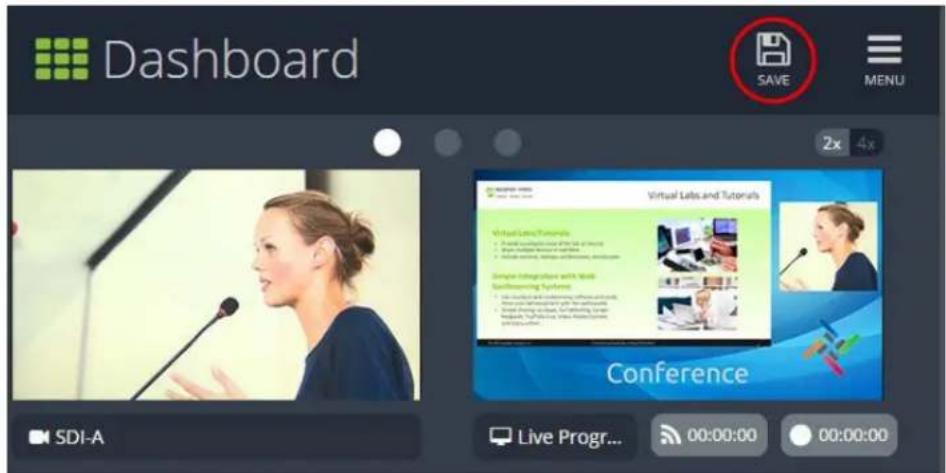
You can navigate between 3 separate sets of Dashboard panels by clicking the circle icons above the first row of panels.
You can also configure each panel set to display either 2 or 4 panels by clicking the 2x/4x icons above the upper-right Dashboard panel.
Monitoring video and audio sources
In the Dashboard interface, you can specify video and audio inputs and view the details for each input.
Video sources
By default, the video inputs section of the Dashboard view lists all inputs configured on your Pearl-2.

- A green circle icon next to the input name means that the video source is connected to your Pearl-2 and a signal is received. Accompanying text to the right of the input name provides the input's resolution.
- A yellow circle icon next to the input name means that your Pearl-2 is not receiving a signal from your source.
- A triangular warning icon next to the input name means there is a source configuration issue that requires your attention.
Configure the video input list
You can customize the video inputs displayed on the Dashboard interface by clicking the Video inputs header.

Click the checkbox next to the name of each source to show or hide sources in the Dashboard view (the Dashboard video input list updates automatically). Make sure to save your changes by clicking the Save icon in the upper-right corner of your browser!
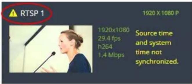
View video source details
Click the name of a video input to display your source in a small dropdown thumbnail view with warning details (if there is a warning icon next to your source's name) and accompanying source details:
• HDMI, SDI, USB video sources display resolution and refresh rate.
• RTSP sources (such as IP cameras) display resolution, frame rate, codec used and bitrate.
Audio sources
By default, the audio inputs section of the Dashboard view lists all inputs configured on your Pearl-2.
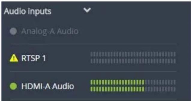
• A grayed-out audio source name means that the audio source is not used in any channels.
- A triangular warning icon next to the input name means there is a source configuration issue that requires your attention. Click the audio source name to display the corresponding warning message.
- A green circle icon next to the audio source name means the source is connected to your Pearl-2. The accompanying VU meter to the right of the input name provides the source's volume level.
Read the VU meter
The on-screen VU meter uses quasi-peak ballistics with samples averaged every 10 ms. The maximum average in each 100 ms period is displayed as a series of colored bars. The following table describes the levels at which the meter changes from green to yellow and red.
Table 11 Audio VU meter levels
| Color Decibel range | |
| Red 0 to -9 dBFS | |
| Yellow -9 to -18 dBFS | |
| Color Decibel range |
| Green -18 dBFS and lower |
Configure the audio input list
You can customize the audio inputs to display in the Dashboard view by clicking the Audio inputs header.

Click the checkbox next to the name of each source to show or hide sources in the Dashboard view (the Dashboard audio input list is updated automatically). Make sure to save your changes by clicking the Save icon in the upper-right corner of your browser!
Configuring and monitoring video outputs
The Dashboard interface allows you to configure video outputs and view output details. By default, both of Pearl-2's HDMI outputs are displayed in the Dashboard interface and cannot be hidden from view.

- If your output name is displayed with green text, it means your output is connected and transmitting to your external display. Accompanying text to the right of the output name provides the output's resolution and frame rate.
- An output name with grayed-out text means your output port is disabled.
- An output name with white text means your output port is enabled but is not connected to an external display.
View video output details
Click the name of a video output to display your output in a small dropdown thumbnail view.

Configure video outputs
You can enable/disable each HDMI output and set your outputs to display a channel or video source. You can also enable or disable output volume (if any).

By default, video output ports are configured to maintain aspect ratio, use the display's default resolution, include audio at 100% and not include the audio VU meter. You can change these defaults in the Admin panel. See Video output ports to learn more about advanced-level video output configuration using the Admin panel.
To configure video outputs:
- Click the Video outputs header text to display the video output configuration box.

- Click the text box next to your desired output port and select a channel or source from the dropdown list.
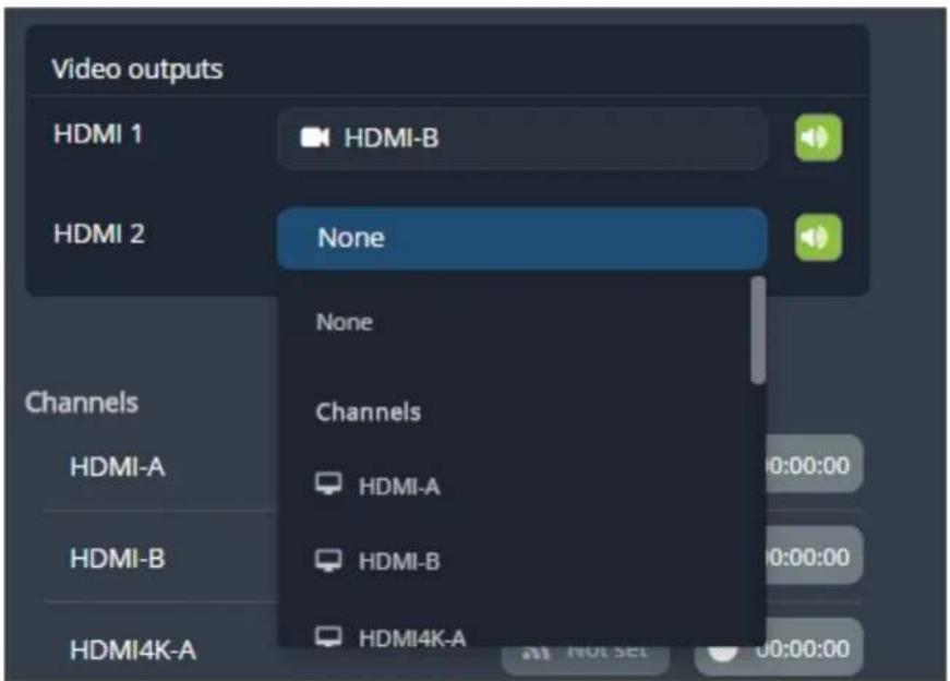
- Click the speaker icon next to the channel/source text box to enable or disable output audio. A green icon means audio is enabled; a gray icon means audio is disabled. (See Disable or enable the audio on
the video output port).

Controlling streaming and recording using Epiphan Live
You can control the streaming and recording of channels and recorders directly from the Epiphan Live Dashboard interface.
Stream and record channels
Streaming and recording control buttons are located under the Channels heading in the Dashboard view.
For each channel, the stream control is the left-most button containing the "signal" icon, and the recording control is the right-most button containing the circle icon. If multiple streams are configured in a channel, individual controls appear for each stream.
![Channels Channel 2 00:00:00 00:00:00 External [192.168.0.205] Not set 00:00:00](/content/2026/06/1365921/images/f57934d7c988b51b346e59d6c5a437c9940dcb95e028abf89df8439d9e593db6.jpg)
When a channel is not being streamed or recorded, the streaming and recording buttons are gray in color and their respective timers are set to 00:00:00. If streaming has not been configured in the Admin panel, the streaming button will display the text "Not set". See Stream to viewers to learn how to configure streaming in the Admin panel.
You can preview a channel by clicking its name to display a small dropdown thumbnail view.
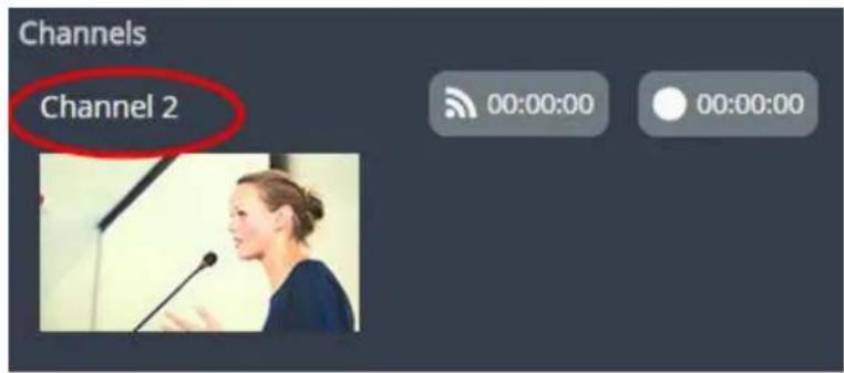
To start streaming and recording a channel, simply click the channel's streaming and/or recording buttons.
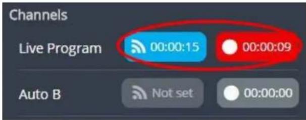
When clicked, the streaming button turns blue in color and the recording button turns red. The timer contained within each respective button also begins to count upward.
Alternatively, you can also control streaming and recording of a channel via the Dashboard's monitoring panels. See Configuring Dashboard panels for visual confidence monitoring for more information.
If the stream is not able to publish, the streaming button flashes blue and displays "ERROR".

In this case, check the streaming configuration settings for your channel in the Admin panel. (See Stream to viewers to learn how to configure a stream).
Record a Admin panel Recorder
In Pearl-2 you can use Recorders to capture multiple channels at once. Epiphan Live Dashboard view allows you to use Recorders with the using the button(s) located in the Recorders section. Note that the Recorders section only appears if you have taken the steps to Add a recorder via the Admin panel.

When a Recorder is not being recorded, the recording button is gray in color and its timers is set to 00:00:00.
To start recording a Recorder, simply click the corresponding button.
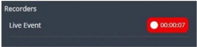
When clicked, the recording button turns red. The timer contained within the button also begins to count upward. Click the button a second time to stop the recording.
Live switching using the Switcher interface
The Epiphan Live Switcher view is a simple interface for live switching between custom layouts while streaming and/or recording. (For information on creating custom layouts in the Admin panel, see Create a custom channel or layout.) Pearl-2's touch screen and the Admin panel are also capable of performing live switching (see Live video mixing / switching).

Performing live switching in one interface (e.g. Epiphan Live) does not dynamically update the visuals in the other interfaces (e.g. the Admin panel and Pearl-2's touch screen). All other interfaces must be manually refreshed to accurately reflect the current live switching layout information.
Topics in this section include:
• Understanding the Switcher interface
• Switching while live streaming and recording
Understanding the Switcher interface
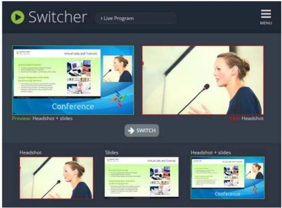
The Switcher view is a simple interface used to seamlessly switch between a channel's custom layouts while live streaming and/or recording. See Create a custom channel or layout for more information on creating custom layouts.
The Switcher interface is accessed from the Menu button in the Dashboard interface. See Understanding the Dashboard interface.

The Switcher view is responsive and automatically adjusts and reposition its elements to fit cleanly within any size web browser window.
See the Elements in the Switcher view table below for a description of each visual element in the Switcher interface.

Table 12 Elements in the Switcher view
| Number | Title Description | |
| 1 | Channel selector | Select from a list of channels (configured via the Admin panel) to display custom layouts specific to your selected channel. Note that when a channel is selected, you can only switch between layouts within that channel. |
| 2 | Menu icon | Displays links to the Dashboard view and the Admin panel when clicked. |
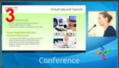
| 3 | Preview panel | Displays a preview of a selected layout, outlined with a green border. When theSwitchbutton is clicked, this preview layout becomes the live layout. SeeSwitching while live streaming and recordingfor more information. |
| 4 | Live view panel | Displays the layout currently being streamed and/or recorded, outlined with a red border. When theSwitchbutton is clicked, this live layout is replaced with the layout in thePreview panel. |
| 5 | Layout selection panel | Displays small previews for all layouts contained within your selected channel. Click a layout from this list to add it to thePreview panel. |




natural_image
Woman speaking at a podium with a microphone, no visible text or symbols



| Number | Title Description | |
| Note that the layout selected for thePreview panelhas a green border and the layout in theLive view panelhas a red border. | ||
| 6 | Switch button | When clicked, the layout in thePreview panelreplaces the layout in theLive view panel, and is immediately reflected in your streaming and/or recording. |
Switching while live streaming and recording
The Switcher interface lets you easily live switch between custom layouts with the simple press of a button.
To switch a layout while live streaming and/or recording:
- Log in to Epiphan Live; the Dashboard view opens by default. See Accessing Epiphan Live.
- Click the Menu icon in the upper-right corner of the Dashboard screen and click Switcher to navigate to the Switcher interface.

- Click the text box next to the "Switcher" header and select your desired channel from the dropdown list (the text box will appear blank if this is your first time configuring the Switcher interface). Note that in the channel dropdown list, channels containing only a single layout are grayed-out and are not selectable.
After selecting your channel from the dropdown, the Switcher interface appears with all of your channel's layouts displayed along the bottom of the page.

The layout currently being streaming and/or recorded is displayed in the Live view panel on the right side of the interface (see Understanding the Switcher interface).

- Click your desired layout at the bottom of the page to dock it in the Preview panel. This is the layout that will be used next in your program.
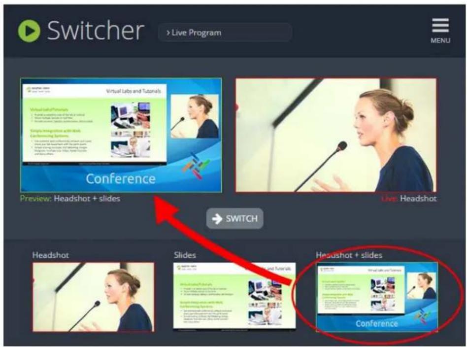
- Click the Switch button in the center of the screen to apply your layout in the Preview panel into your live stream/recording program.

From here, you can prepare to apply another layout to your program by selecting a new layout from the list and docking it into the Preview panel.
Your Recordings
All recordings made in Epiphan Live are saved to the Your recordings panel.

After recoding a file, you can manage it and any other files using the following tools on the page:
| Number | Title Description | |
| 1 | Date selector | Select aFromand aTodate from the pop-up calendar to create a date range. Then click Apply. Only recordings that were recorded within that time frame appear in the list below. |
| 2 | File details | Each heading in the list gives information about that category. Clicking onDateorganizes the list chronologically by the date the recording began. |
| 3 | Files | Each recorded file that falls within the search parameters appears in this list, including important metadata about the file. Clicking on the file selects it so that it can be managed through the other tools on the page. You may also download or delete an individual file by using the action items at the end of the file line. Click on the file name to rename the file. |
| 4 | Page indicators | The page number indicates which page of results you are currently viewing, and how many pages of results are there. The buttons allow you to move between pages one at a time, or straight to the beginning or end of the list. You can also change which page you are on by typing a valid page number into the text box. |
| 5 | Select all Click this button to select all files on the page. | |
| 6 | Delete all | Click this button to delete all files on the list. Be cautious with this button, as there is no file retrieval system. |
| 7 | Delete | Click this button to delete all selected files. Be cautious with this button, as there is no file retrieval system. |
| 8 | Download Click this button to download all selected files to your local hard drive. | |
PART 1: Setup
If you followed through the quick start guide, you already have a basic configuration and possibly a recording of an input. Before you tweak the channel or configure more, this part of the manual helps you to get your Pearl-2 properly configured for your network.
Topics covered:
- Connect to the Admin panel
- Configure the touch screen
- User administration
• View system information - Configure network settings
- Configure date and time
- Configuration presets
- Restrict viewers by IP address
Rackmount installation
All Pearl-2 models can be used in desktop mode, with the system placed on any flat, stable surface. They are also all rackmountable into fixed racks or portable rack cases like the one depicted below.

natural_image
Stage setup with a large electronic device displaying video callouts, set against a colorful stage backdrop with spotlights and spotlights (no visible text or symbols)If you purchased Pearl-2 Rackmount or Pearl-2 Rackmount Twin, you can install your system directly into a 19-inch rack. For the smaller, portable Pearl-2 model, you can purchase our optional rackmount shelf for installation in a rack. (Instructions for the rackmount shelf are included with the shelf.)
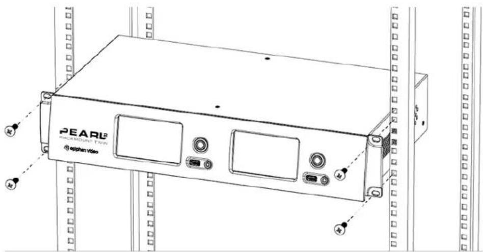
To install Pearl-2 Rackmount or Pearl-2 Rackmount Twin in a 19-inch rack:
- Ensure you have the correct bolts needed for your rack (not included). Pearl-2's rackmount holes are sized to work with both threaded and non-threaded mounting systems.
- Carefully slide the system into and available 2U space in your 19-inch rack.
- Attach four bolts as shown below.
The Admin panel
Pearl-2 is managed from a web interface. This means to perform administrative tasks with Pearl-2 you use an internet browser on a PC (or laptop, or tablet) connected to the same local Ethernet network.
Connect to the Admin panel
If you know the IP address of the system you may type it into the address bar of your web browser.
http://
However, if this is the first time you access your system, you likely don't know the IP address, so you can use one of the following connection methods:
For networks with DHCP use one of the following procedures:
- Connect using the touch screen
- Connect via DNS-based service discovery
- Connect via the Epiphan discovery utility
For networks without DHCP, use the following procedure:
- Connect via persistent static IP address

You can also connect to Epiphan Live – a simple and easy-to-use web and tablet interface for confidence monitoring, streaming/recording control and live switching operation. See Epiphan Live for more information.
Connect using the touch screen
To connect to the Admin panel, you need to know your Pearl-2's IP address. There are a number of ways to determine the IP address, but the simplest way is to use the touch screen, if it is enabled.
To connect to the Admin panel using the touch screen to determine the IP address:
-
Obtain the IP address using the touch screen:
-
from a single channel view or grid view, touch the system settings (gears) button then touch System Status; or
- if your system doesn't have any channels showing, touch the screen anywhere to move to the system settings screen then touch System Status.
   | |||
| Device | Status | ||
| Serial | D569D134 | Date | 1-Jun-2015 |
| Grabber | D2P280194 | Time | 16:18:46 |
| Firmware | 3.15.1a | Uptime | 2:37:09 |
| t, °C | 77.0 / 53.6 | ||
| Network | Storage | ||
| IP Address | 192.168.0.183 | 929.8 free of 929.9 GB | |
| MAC | C0:3F:D5:69:D1:34 | 100% | |
Device
| Serial | D569D134 |
| Grabber | D2P280194 |
| Firmware | 3.15.1a |
Status
| Date | 1-Jun-2015 |
| Time | 16:18:46 |
| Uptime | 2:37:09 |
| t, °C | 77.0 / 53.6 |
Network
| IP Address | 192.168.0.183 |
| MAC | C0:3F:D5:69:D1:34 |
Storage
| 929.8 free of 929.9 GB |
| 100% |
- Type the following string into the address bar of your web browser on your admin computer, where
is the ip address of your Pearl-2.
http://
For example: http://192.168.1.163/admin
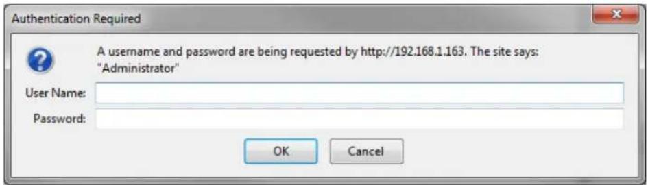
- Enter the user name and password then click OK. The administrative user is 'admin'. Initially no password is set. To set a password follow the procedure outlined in User administration.
Connect via DNS-based service discovery
Pearl-2 uses DNS-based messages to advertise details about itself, including its host name. With a compatible utility installed on your computer, you can access the system simply by typing its serial number and the suffix ".local" into the address bar of your browser.
To ensure you have compatible software, refer to the following table.
Table 13 Installing Bonjour Print Services
| System Action Needed | |
| Microsoft Windows | You must install Bonjour Print Services:1. Use the following URL - http://support.apple.com/kb/DL9992. Click Download.3. Follow the system prompts to download and install the application. |
| Mac OS X | The Bonjour software used for service discovery is built into the Mac OS. No special actions are needed. |
| Linux | The Avahi implementation used for DNS-based discovery is shipped with most Linux distributions. If necessary, check with your administrator to ensure you have the Avahi package installed. |
To access Pearl-2's Admin panel via DNS service discovery:
-
Find the system's serial number. It is printed on a sticker on the back of the system, or available on the system information display on the touch screen. To access the serial number:
-
from the "no channels" screen, touch the screen anywhere to move to the system information screen;
• from a single channel view, touch the system information button; or
• from the grid view, select a channel, then touch the system information button. -
Type the following string into the address bar of your web browser on your admin computer, where
is the serial number of your Pearl-2:
http://
For example: http://95dd40d5.local/admin
- Enter the user name and password then click OK. The administrative user is 'admin'. Initially no password is set. To set a password follow the procedure outlined in User administration.
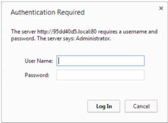
- Optionally, navigate to the Network link under the Configuration heading and note the IP address of the system.
Connect via the Epiphan discovery utility
Epiphan provides a utility for discovering Epiphan systems on your network. The Epiphan network discovery utility is a 32-bit Windows executable that works on most 32-bit and 64-bit Windows operating systems. Download and install the utility via this link: https://www.epiphan.com/downloads/NetworkDiscovery.exe.
To access the Pearl-2's Admin panel via the Epiphan discovery utility:
- Launch the discovery utility.
- Click Search to find all the Epiphan systems on the network; a list similar to the following appears.
![VGA2Ethernet DirectShow Setup File Device View Help Pearl [PRLD560515F] s/n: PRLD560515F address: 192.168.0.116 Device OK Stream preview 1920x1080 27.0 Hz Refresh Stream properties Name: Pearl [PRLD560515F] Address: 192.168.0.116 Password: Add... Remove Search Advanced... Web config...](/content/2026/06/1365921/images/1cdc25b6ea724c857cf02bec32116a95fa5f865180cf2769f1fa97d6199162ed.jpg)
- If more than one system appears, select the one you wish to configure by matching the serial number listed with the serial number marked on the back of the system.
- Optionally, note the IP Address shown in the stream properties. Use this for quicker access to the system on future configuration sessions.
- Click the Web config button; your browser will open and point to the Admin panel page.
http://
- Enter the user name and password then click OK. The administrative user is 'admin'. Initially no password is set. To set a password follow the procedure outlined in User administration.
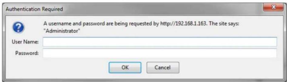
Connect via persistent static IP address
Your Pearl-2 has a default persistent static IP address, also known as the recovery IP address. If ever you need to set it up on a network that does not support DHCP, or you need to recover from a previous static IP address setting, you can use this method to connect directly to the system for configuration.
To perform this procedure you will need a workstation computer for which you are able to modify network settings.
Pearl-2 is pre-configured with the following static address defaults:
• IP Address: 192.168.255.250
• Netmask: 255.255.255.252
- Username: admin
- Password: your admin password (by default set to no password)
To access Pearl-2's Admin panel via the persistent static IP address:
- Establish an Ethernet connection between Pearl-2 and the workstation by one of the following methods:
a. Connect the system to a local Ethernet network shared with the workstation.
b. Connect the system directly to the workstation's Ethernet port using either a regular or a crossover Ethernet cable. - Record the network settings of the workstation being used to connect to Pearl-2 so that they can be restored later.
- Temporarily change the network configuration on the workstation to the following:
a. Use Static IP assignment
b. IP address: 192.168.255.249
c. Subnet mask: 255.255.255.252 - Start a web browser on the workstation and browse to: http://192.168.255.250/admin/
- Log in as the administrator user with the user name admin and the admin password (by default there is no password); the Admin panel opens.
- Click the Networking link in the Configuration menu.
- Select the radio button to use a static address and configure the system with a static IP address and network settings relevant to the network being used. For specific details about the settings presented, see Configure network settings.
- Restore the previously saved network configurations on the workstation.
User administration
Pearl-2 has three configured users:
- admin
- operator
- viewer
By default, none of these users have passwords. For security purposes you should add passwords to the admin and operator accounts.
This section describes the following user administration topics:
• User types and privileges
- Set or change user passwords
- Remove user passwords
• Overcome lost passwords
- Configure LDAP
• Change the logged-in user
- Restrict viewers by IP address
User types and privileges
Pearl-2's three user accounts are admin, operator and viewer. The user account names cannot be changed and the accounts cannot be disabled. By default, none of the accounts have passwords.
Admin
The admin account is used for all system configuration. This user has access to all options in the Admin panel.
Operator
The operator account allows users limited Pearl-2 configuration control.
If an operator does not have the privileges to apply a particular configuration in the Admin panel, the Apply button appears grayed-out in color and is not clickable (as shown in the image below).

The operator account is intended for an operator to configure sources, control recordings (start and stop); rename, download and delete recordings; switch layouts while live streaming or perform network diagnostics.
Viewer
The viewer account is for all end-users who are permitted to view the streamed channels. By default, when there is no password, users are not prompted for a username and password when viewing a channel. The viewer username and password prompt appears only when there is a viewer password set.
In addition to the global viewer account, each channel can set a viewer password that overrides the global value. See Restrict access to streams for viewers.
Current user
When logged in to the Admin panel, the current username is displayed at the top right corner of the screen.

User privileges
The following table outlines the privileges for each user:
Table 14 User privileges in the Admin panel
| Action or Menu Option viewer operator admin | |||
| View Channel Output | ✓ ✓ ✓ | ||
| Channel Operations | |||
| View Channel Configuration | ✓ | ✓ | |
| Rename a Channel | ✓ | ||
| Configure Stream Channel | ✓ | ||
| Configure Stream Sources | ✓ | ||
| Publish a Stream | ✓ | ||
| Configure Branding for a Channel | ✓ | ||
| Switch Layouts while Streaming/Recording | ✓ | ✓ | |
| Start the Stream Recorder | ✓ | ✓ | |
| Stop the Stream Recorder | ✓ | ✓ | |
| View Recorded Files List | ✓ | ✓ | |
| Rename Recorded Files | ✓ | ✓ | |
| Download Recorded Files | ✓ | ✓ | |
| Delete Recorded Files | ✓ | ✓ | |
| Source Operations | |||
| View Source Configuration | ✓ | ✓ | |
| Rename Source | ✓ | ||
| Configure Source | ✓ | ✓ | |
| View Source Snapshot | ✓ | ✓ | |
| System Configuration Operations | |||
| View System Configuration | ✓ | ✓ | |
| Configure Automatic File Upload | ✓ | ||
| Select External USB Drive Behavior | ✓ | ||
| Configure FTP Server | √ | ||
| Configure UPnP Sharing | √ | ||
| Configure Network Address | √ | ||
| Configure USB Tethering | √ | ||
| Perform Network Diagnostics | √ | √ | |
| Configure Date and Time preferences | √ | ||
| Set or Change User Passwords | √ | ||
| Configure the Touch Screen | √ | ||
| Configure Serial Port Flow Control | √ | ||
| Upload Branding Images | √ | ||
| Upload Branding Templates | √ | ||
| Select Branding Template | √ | ||
| Enable Remote Support | √ | ||
| Backup Device Configuration | √ | ||
| Restore Device Configuration | √ | ||
| Restore Factory Configuration | √ | ||
| Reboot Device (via Admin panel) | √ | ||
| Shutdown Device (via Admin panel) | √ | ||
| Configure Time Until Next Disk Check | √ | ||
| Perform Disk Check | √ | ||
| View Disk Information | √ | √ | |
| Upgrade Firmware | √ | ||
| View System Information | √ | √ | |
Set or change user passwords
By default, admin, operator and viewer have no assigned passwords. Both the admin and the operator user have access to the Admin panel, so you should always set a password for both admin and operator accounts. Refer to your system administrator for your organization's specific password requirements.

If the admin password is defined and the operator password is undefined, then the operator uses the admin password by default.
In addition to setting global passwords for viewers, you can also set access passwords and IP restrictions on a per-channel basis from the channel's Streaming page. See Restrict viewers by IP address.
Passwords are case sensitive and can use all alpha-numeric keys in the ASCII range. Your password can be up to 255 characters long, but should not include any spaces.

Setting a user's password causes the user to be logged out. Be ready to log back in with the new admin password or have operators and viewers log in with the appropriate new password. Viewers may need to refresh their browser window or press play in their media player.
If you lose the admin password, refer to the section Overcome lost passwords.

Changing the admin password while live streaming disrupts the view of the stream for viewer-level users. Complete any admin password changes when there is no live stream in progress.
To set a user password:
- Login to the Admin panel as admin. See Connect to the Admin panel.
- Select the Access passwords link in the Configuration menu; the password configuration page opens.
- Highlight and delete the current password for your selected user (the password is currently masked as dots).

For security reasons, the current password appears as eight dots regardless of password length, and even if there is no password set.
-
Highlight and delete the confirmation password for the selected user.
-
Select the user's password field and type a new password for the user.

The new password must have between 1-255 alpha-numeric characters or special characters with no spaces. Passwords are case sensitive.
-
Select the user's password confirmation field and confirm the new password.
-
Click Apply.
-
If you were logged in as the user whose password you just changed, you are logged out and must log back in with the new password. If you added or changed the viewer's password, all viewer's stream will pause until they log in with the new password.
If desired, you may specify multiple account passwords on the same page before clicking Apply.
Remove user passwords
If you want to remove passwords for one or more user accounts, you may do so via the Admin panel. If you don't remember the admin password, refer to the section Overcome lost passwords.
Note that viewer passwords can be set on a per-channel basis.

Clearing a user's password will cause that user to be logged out. Be ready to log back in with the new admin password. If viewers are watching the broadcast when the viewer password is cleared they will be logged out. Viewers may need to refresh their browser window or press play in their media player to trigger the login prompt.
To clear a user's password:
- Login to the Admin panel as admin. See Connect to the Admin panel.
- Select the Access passwords link in the Configuration menu; the password configuration page opens.
- Highlight and delete the current password for your selected user (the password is currently masked as dots).

For security purposes, the current password appears as eight dots regardless of password length, and even if there is no password set.
- Highlight and delete the confirmation password for the selected user.
- Click Apply.
- If you were logged in as the user whose password you just cleared, you are logged out and must log back in without a password. If you cleared the viewer's password, all viewer streams will pause until they log in without a password.
To clear a user's password on a specific channel:
- Login to the Admin panel as admin. See Connect to the Admin panel.
- Click the Streaming link for the channel; the channel's Streaming configuration page opens.
- From the Access control section do one of the two following things:
a. Clear the viewer password field; or
b. Select Use global settings from the access control drop down.
- Click Apply.
Overcome lost passwords
If you have lost the password for the operator or viewer account, you can log in to the Admin panel and reset the password using the procedure described in Set or change user passwords.
If you have lost the admin password and you have remote support enabled on the system, you can contact Epiphan support to request a remote password change. See Support. If remote support is disabled, you will need to return the system to Epiphan for password recovery. Contact Epiphan support to discuss this option.
You might instead choose to regain access by resetting Pearl-2 to its factory default settings using the touch screen. Just Apply a configuration preset using the touch screen
Configure LDAP
You can use the Lightweight Directory Access Protocol (LDAP) for authentication into the system. Specify user roles by using group DNs for users who log in as the administrator, operator or as a viewer.

The system has only one admin user and one operator: LDAP users log in as either the admin or operator, they do not have their own private profiles.

When enabled, LDAP authentication is an alternative to the regular system usernames and passwords. You may still login as admin, operator or viewer using the passwords for those accounts. Furthermore, any LDAP users with the name admin, operator or viewer are ignored. The local accounts are used instead.
For security reasons, you should configure passwords for the local accounts. See Configure LDAP.
These instructions assume you have a pre-configured LDAP server. The server must support anonymous binding or have a special bind account with search access privileges. (Note that Active Directory does not support anonymous binding.)

LDAP referrals, restrictions and failovers are not supported.
To configure LDAP authentication for your Pearl-2:
- Login to the Admin panel as admin. See Connect to the Admin panel.
- Select the Access passwords link in the Configuration menu; the password configuration page opens.
- Scroll to the LDAP authentication section.
![LDAP authentication: Enable LDAP authentication Server address[:port] Connection encryption No encryption ▼ Bind DN Bind password Base DN Search attribute Administrators (group DN) Operators (group DN) Viewers (group DN) Apply](/content/2026/06/1365921/images/6aeacd6f2f92936a93b8ea0f9d8565e138f12683eb88433822ba503a7f331fb6.jpg)
- Click the Enable LDAP authentication checkbox to enable LDAP authentication (or uncheck to disable).
- Specify the server IP address and (optional) port for your LDAP server (i.e. 192.168.1.101:389) in the Server address[:port] field.
- Use the Connection encryption drop-down to specify the type of encryption, if any used by your LDAP server.
| Connection encryption | Description/Default port used |
| No Encryption No encryption is used to connect to the LDAP server. The default port is 389. | |
| SSL SSL encryption is used to connect to the LDAP server. The default port is 636. | |
| TLS/STARTTLS | The connection is initially unencrypted then upgraded to TLS encryption is used. The default port is 389. |
- Specify the fully qualified DN and password for LDAP bind in the Bind DN and Bind password fields. (The password masked as dots on the screen.) These fields are only needed if your LDAP server does not support anonymous binding.
-
In Base DN, specify the baseObject in which to search for entries. The system will search this object and the whole subtree starting at the base DN.
-
By default the search attribute is uid, which is suitable for a unix environment. Specify a different value in the Search attribute field, if needed. For Active Directory environments, specify userPrincipalName. The value of this attribute must be unique in the Base DN.
-
In the Administrators (group DN) field, specify the distinguished name of the group users must be part of to be logged in as the administrator. Users must have the member or uniqueMember attribute for the specified group to be granted Administrator access. If left blank, LDAP is not supported for Administrators (but can still be used for Operators and Viewers).
-
In the Operators (group DN) field, specify the distinguished name of the group users must be part of to be logged in as the operator. Users must have the member or unqueMember attribute for the specified group to be granted Operator access. If left blank, LDAP is not supported for Operators (but can still be used for Administrators and Viewers).
-
In the Viewers (group DN) field, specify the distinguished name of the group users must be part of to be logged in as a viewer. Users must have the member or unqueMember attribute for the specified group to be granted Viewer access. If left blank, LDAP is not supported for Viewers (but can still be used for Administrators and Operators).
-
Click Apply.
When a user of the LDAP server next visits the admin or viewer page for the system, the system prompts for use the username and password. For ActiveDirectory servers, the user needs to enter his fully qualified username (i.e. username@domainname) in addition to his LDAP password.

Users are required to authenticate once to the system and one time per channel they view. Therefore users see a prompt to log in to the system (the system name is shown) and a second time to log in to the channel (the channel name is shown).

In one case, LDAP replaces the local viewer account instead of working side-by-side with it.
When LDAP is enabled and the viewer account has no password (either there is no global viewer password or the channel overrides the global password with a blank password), the viewer must authentication with LDAP, he may not alternatively use the viewer account with a blank password.
Change the logged-in user
When you log in to the Admin panel as admin or operator, your browser remembers this configuration and automatically logs you in as the same user when you go back to the site.
Sometimes you need to change from operator to admin, or vice versa.
To change the logged-in user:
- Click the logout button at the top right of the screen (beside your user name); you are logged out.


Some browsers may require you click the button twice before the log out action executes.
Restrict viewers by IP address
Pearl-2 permits you to restrict which computers can access broadcasts by building a list of allowed and/or denied IP addresses. You can do this at a global level for the system and can also override these settings on a per-channel basis. Both global and per-channel configuration procedures are described below.

You cannot set per-channel passwords and IP restrictions if you stream using HTTP Live Streaming (HLS).
If your viewer account has a password, your viewers must connect to the system from a computer (or gateway) with a permitted IP address and must also supply the username (viewer) and password before they can view the broadcast.
To restrict access by IP address, you need to know the IP addresses or range of addresses for your viewers. By default, all IP addresses are allowed to connect to the broadcast.
If you're not familiar with creating allow/deny lists, refer to the examples below this procedure for assistance with crafting your lists.

IP address restriction is valid for the viewer only and does not affect the Admin panel or the mobile configuration interface.
To restrict viewers by IP address:
-
Login to the Admin panel as admin. See Connect to the Admin panel.
-
Select the Access passwords link in the Configuration menu; the password configuration page opens.
- Type allowed IP addresses or address ranges in the Allow IP's field. Separate addresses with a comma.
- Type denied IP addresses or address ranges in the Deny IP's field. Separate addresses with a comma.
- Click Apply.
To restrict viewers of a specific channel by IP address:
- Login to the Admin panel as admin. See Connect to the Admin panel.
- Select the Streaming link for the desired channel; the streaming configuration page opens.
- From the Access Control drop-down, select Use these Settings; local password and Allow/Deny IP lists are enabled.
- If desired, type a password for the viewer in the Viewer Password field.
- Type allowed IP addresses or address ranges in the Allow IP's field. Separate addresses with a comma.
- Type denied IP addresses or address ranges in the Deny IP's field. Separate addresses with a comma.
- Click Apply.
If a user attempts to connect to the stream from a disallowed IP address, access is denied. If connecting by internet browser, the message "IP address rejected." is displayed.
The following table describes the applicable fields.
Table 15 IP Based Restriction Fields
| Label Description/Options | |
| Allow IP's | Enter individual IP addresses or IP address ranges, separated by commas. To specify a range, use a hyphen (-). Optional spaces improve readability.Users connecting from addresses in this list are permitted to view broadcasts from the system, provided their IP address is not in the Deny IP's list.To allow all except IP addresses in the deny list, if any, leave the field blank.You can use the Allow list by itself, or in conjunction with the Deny IP's list as an exception to a rule in the allow list. |
| Deny IP's | Enter individual IP addresses or IP address ranges, separated by commas. To specify a range, use a hyphen (-). Optional spaces improve readability.Users connecting from addresses in this list are not allowed to view broadcasts from the system, unless their IP address is in the Allow IP's list. If a specific IP address is in both lists access to the stream is denied.You can use the Deny list by itself, or in conjunction with the Allow IP's list as an exceptionto a rule in the allow list. |
IP restriction examples
Allow list with distinct IP addresses
The simplest allow/deny list is to use the list of known IP addresses to craft a list of allowed IP addresses. All other addresses are denied access to the broadcast.
For example if your system is accessible on your local area network (LAN) and you want to make sure only the CEO's specific desktop, laptop and tablet computers (with IP Addresses 192.168.1.50, 192.168.1.51, and 192.165.1.75, respectively) can connect to the broadcast, construct the following allow list:
Allow: 192.168.1.50, 192.168.1.51, 192.168.1.75
Allow list with a range of IP addresses
Sometimes you'll want a range of computer IP addresses to connect to your system. This may happen when you have one range of IP addresses assigned to desktop computers (i.e. in the range 192.168.1.1 to 192.168.1.100) and another range assigned to boardroom computers (i.e. the range 192.168.1.200 to 192.168.1.250). If you only want the boardroom computers to connect to broadcasts from the system you can specify the range of boardroom IP addresses rather than needing to type in each individual address. The allow list looks as follows:
Allow: 192.168.1.200-192.168.1.250
Note that we could have specified two of the IP addresses in the previous example as a range.
Allow list with a range of IP addresses and one or more specific IP addresses
Putting the first two examples together, we want to permit access to IP addresses in the range of boardroom computers (192.168.1.200-192.168.1.250) and also want to add the desktop, laptop and tablet computers of the CEO (IP addresses 192.168.1.50, 192.168.1.51, and 192.168.1.75, respectively). Note the first two IP addresses are consecutive, so they can be added as a second range. Add these IP addresses to the list as follows:
Allow: 192.168.1.200-192.168.1.250, 192.168.1.50-192.168.1.51, 192.168.1.75
Your list can have multiple ranges and multiple distinct IP addresses, provided they are separated by commas.
Deny list with distinct IP addresses
Another simple allow/deny list is to use the list of known IP addresses to list specific denied IP addresses. All other addresses are allowed access to the broadcast.
For example imagine your system is accessible on your local area network (LAN) and you want to allow any computer on the LAN can access the stream except your publicly-accessible boardroom (with IP address 192.168.1.211). You can use the following deny list (leave the allow list empty) to permit all computers except the boardroom computer:
Deny: 192.168.1.211
As with allow lists, your deny list can specify a range of IP addresses, and can specify multiple ranges or distinct IP addresses in a comma-separated list.
Allow list with a range of IP addresses, distinct IP addresses and an exception
Building on the previous examples, consider the situation where you want the CEO's computers (192.168.1.50, 192.168.1.51, 192.168.75) and all boardroom computers (192.168.1.200-192.168.1.250) to access the broadcast, with the exception of the public boardroom computer (192.168.1.211). Use both allow and deny lists to create the rule as follows:
Allow: 192.168.1.200-192.168.1.250, 192.168.1.50-192.168.1.51, 192.168.1.75
Deny: 192.168.1.211
Both lists can have multiple ranges and multiple distinct IP addresses, provided they are separated by commas.
Deny list with a range of IP addresses
Converse to the previous examples, consider the situation where you want every computer on the network to access the broadcast, with the exception of the CEO's desktop, laptop and tablet computers. Additionally, boardroom computers should not be permitted with the exception of the cafeteria computer (IP address 192.168.1.222).
The deny list is an "exception" list for the allow list. So to craft the rule described above we need to allow all the computers in the local subnet, then deny specific sub-ranges including two groups of boardroom computers ensuring the cafeteria computer's IP address is not in the deny list:
Allow: 192.168.1.1-192.168.1.250
Deny: 192.168.1.200-192.168.1.221, 192.168.1.223-192.168.1.250, 192.168.1.50-192.168.1.51, 192.168.1.75
Pearl-2's touch screen
Pearl-2's front panel includes a touch screen display used for confidence monitoring, basic configuration and streaming/recording operation.
Use the touch screen to view system information, configure network settings, load configuration presets, view configured channels, review audio levels, and control channel streaming/recording.
By default, the screen and all its features are enabled. You can configure whether or not the touch screen is active and which features are enabled. See Configure the touch screen.

Pearl-2's touch screen is capacitive. Use your finger or a specially designed soft-tipped capacitive stylus with firm but gentle pressure. Pressing too hard or using something other than a fingertip or capacitive stylus can result in damage to the screen.
This section describes how to use the touch screen and provides an overview of the functionality available through the screen.
- Touchscreen overview
• View system information
• Channel monitoring - Pearl-2's audio jack
• One Touch streaming and recording control
• Control recording of individual channels
• Control streaming of individual channels
• View AFU status - Configure the touch screen
Touchscreen overview
While Pearl-2 is booting, the following image appears on the touch screen (if the screen is enabled).

After boot up is complete, Pearl-2 displays a grid view providing an overview of all configured channels.
If you have no sources plugged in, or if no plugged in source is sending a signal, the grid view shows the two auto channels with no signal (see Use the automatic channels Auto A and Auto B for more details on auto channels):

With sources plugged into at least one input of row A and row B, the grid view looks more like this:

From this screen, touch either channel to go to the individual channel screen, or touch the gear symbol to go to the system settings screen. From the single channel screen touch the gear to go to system settings or touch the button with four squares to return to the grid.

If you delete the automatic channels Auto A or Auto B, and have no other channels configured, Pearl-2 shows a no channels screen. Touch anywhere on this screen to go to the system settings screen.
No Channels

There are no channels Check your device settings
If the touch screen is configured not to show channel previews, the screen shows the following preview disabled message. Touch anywhere to on this screen to go to the system settings screen.
Preview is disabled

Check your device settings
View system information
Useful when first setting up Pearl-2, for finding the system serial number or to check the installed firmware version, the touch screen shows you basic information about your Pearl-2. If desired, you can choose to disable this screen. See Configure the touch screen.
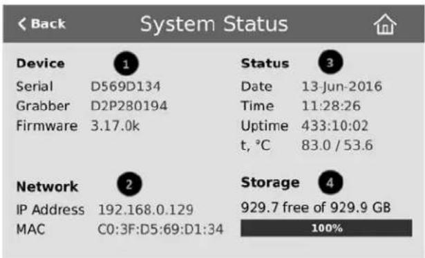
| Label Description | |
 | Device InformationSerial numbervideo grabber numberFirmware version |
 | Network InformationIP AddressMAC Address |
 | Device StatusSystem dateSystem timeUptimeTemperature in degrees Celsius |
 | Storage Information (when available)Disk space availablePictogram of available disk space |
To show system information on the touch screen:
- If the system settings button (gear) is not on the screen, tap the screen once to turn on the control buttons.
- If the system settings button is still not visible, it is disabled in the system's Touch screen configuration.
See Configure the touch screen to enable system information.
- Touch the system settings button (gear) on the screen.

- Touch System Status to see the System Status page.
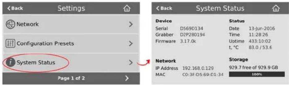
To close the system information screen:
- Touch Back to return to the System Settings screen, or the Home icon to return to the channel view.
Channel monitoring
Use Pearl-2's front-panel screen to have complete confidence about what you're capturing. View audio levels and a preview of the captured video for each channel. Change between individual channels or view a grid of all channels using on-screen navigation buttons. You can also directly monitor audio quality using the 3.5 mm audio jack located at the front of the device. Read more about Pearl-2's audio jack.
You may also be interested in learning about video switching from the touch screen, see Live video mixing / switching.
Individual channel monitoring

Table 16 Parts of the touch screen in individual channel view
| Item Description | |
| 1 Channel name. | |
| 2 | Streaming status (gray means streaming is stopped, flashing blue means streaming is started). |
| 3 Streaming timer (time since streaming was started). | |
| 4 | Recording status (bright red and flashing means recording is started). |
| 5 Recording timer (time since recording was started). | |
| 6 and 7 | Switch to the previous channel and next channel, respectively. (Note that these arrow icons fade when the touch screen is idle (i.e. untouched) for several seconds. Touch the touch screen to make these icons reappear.) |
| 8 Audio VU meter (see chart below for decibel ranges). | |
| 9 | Audio monitoring volume control icon. Touch to change volume level (see Pearl-2's audio jack for more information). |
| 10 | Live switching layout view icon. See Live video mixing / switching for more information on live switching using this view. |
| 11 | Grid view icon. See Grid-view channel monitoring for more information. |
| 12 | Single touch control icon. See One Touch streaming and recording control. |
| 13 System settings icon. See View system information. | |
To switch between available channels:
- If necessary, tap the screen once to turn it on.
- If necessary, tap the screen once to display controls on the channel view.
- Touch the left or right controls on at the side of the channel display; the screen displays the next channel.
To change from grid view to an individual channel view:
- If necessary, tap the screen once to turn it on.
- Touch any channel in the grid view; the screen displays the selected channel.
The on-screen VU meter uses quasi-peak ballistics with samples averaged every 10 ms. The maximum average in each 100 ms period is displayed as a series of colored bars. The following table describes the levels at which the meter changes from green to yellow and red.
Table 17 Audio VU meter levels
| Color Decibel range | |
| Red 0 to -9 dBFS | |
| Yellow -9 to -18 dBFS | |
| Green -18 dBFS and lower | |
Grid-view channel monitoring
Depending on the number of configured channels, the grid view will show 2, 3, 4, 5 or 6 channels at once.
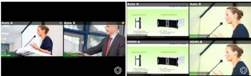
Table 18 Parts of the touch screen in grid view
| Location Description | |
| Top left of channel Channel name | |
| Top right of channel | Streaming (left) and recording (right) indicators:(no dots) Streaming is disabled and recording is stopped. Streaming is stopped and recording is stopped. Streaming is stopped and recording is stopped. Streaming is started and recording is stopped. Streaming is started and recording is stopped. Streaming has an error and recording is stopped. Streaming has an error and recording is stopped. Streaming is stopped and recording is started. Streaming is stopped and recording is started. Streaming is started and recording is started. Streaming is started and recording is started.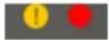 Streaming has an error and recording is started. Streaming has an error and recording is started. Streaming is disabled and recording is started.(Stop and start recording from the individual channel view.) Streaming is disabled and recording is started.(Stop and start recording from the individual channel view.) |
| Bottom left of channel | Audio level indicator. See Audio VU meter for description of levels. |
| Lower right corner of screen | Gear icon. Used to access settings. |
To change from individual channel view to grid view:
- If necessary, tap the screen once to turn it on.
- If necessary, tap the screen once to display controls on the channel view.
- Touch the grid view button; the screen displays the grid view
Pearl-2's audio jack
Pearl-2's front panel includes a 3.5 mm audio jack for audio monitoring.
Audio monitoring
To use the audio monitor, plug speakers or a microphone into the 3.5 mm audio jack.

Use the touch screen to select a channel, that channel's audio is played through the speakers or headphone. The audio played is always the audio corresponding to the layout that is currently live.
Adjust audio monitoring volume
You can adjust audio monitoring volume by touching the headphones icon on the touch screen.
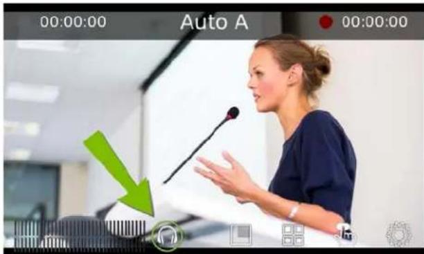
Each touch on the headphones icon increases the audio monitoring volume by 25% to a maximum volume of 100%. Touching the headphones icon when audio monitoring is at 100% mutes the volume. You can also mute (and unmute) the audio monitoring volume by pressing and holding the headphones icon.

Volume is muted.

25% volume.
50% volume.

75% volume.

100% volume.
Audio VU meter
A VU meter on the touchscreen shows the audio levels for the selected channel. A quasi-peak sampling algorithm is used and the value is displayed in dBFS (decibels relative to full scale). Colored bars (from green to red) represent the current sound level.

Table 19 Audio VU meter levels
| Color Decibel range | |
| Red 0 to -9 dBFS | |
| Yellow -9 to -18 dBFS | |
| Green -18 dBFS and lower | |
Control recording of individual channels
Pearl-2's touch screen gives you freedom to start and stop recording your channels individually without needing to log in to the Admin panel.
Simply scroll to the channel you wish to control and press the start or stop recording button.
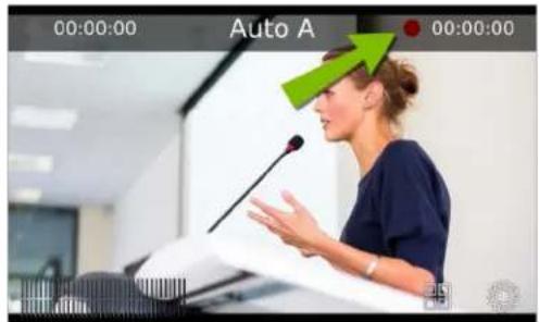

Pearl-2 also features "One Touch" recording/streaming control which allows you to control your recording and streaming across any number of specified channels and recorders simultaneously with the touch of a button. See One Touch streaming and recording control for more information.
To start recording a channel:
- If necessary, tap the screen once to turn it on.
- If the grid view is showing, tap the channel for which you wish to control recording; the screen displays the channel.
- If necessary, tap the screen once to display controls on the channel view.
- Touch the red record button (see above) at the top right of the screen; recording starts and a timer is displayed to show the length of the recording.

To stop recording:
- If necessary, tap the screen once to turn it on.
- If the grid view is showing, tap the channel for which you wish to control recording; the screen displays the channel.
- If necessary, tap the screen once to display controls on the channel view.
- Touch the red record button (see above) at the top right of the screen; recording stops and the timer disappears.

Control streaming of individual channels
Pearl-2's touch screen gives you freedom to start and stop streaming without needing to log in to the Admin panel.
Simply scroll to the channel you wish to control and press the start or stop streaming button on the touchscreen.
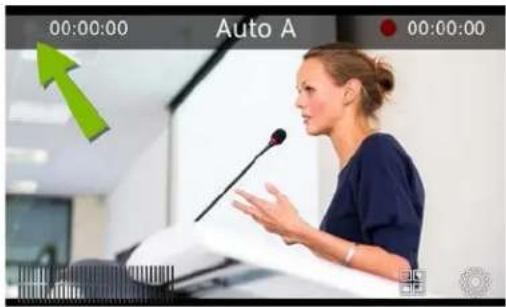

Pearl also features "One Touch" recording/streaming control which allows you to control your recording and streaming across any number of specified channels and recorders simultaneously with the touch of a button. See One Touch streaming and recording control for more information.
To start streaming a channel:
- If necessary, tap the screen once to turn it on.
- If the grid view is showing, tap the channel for which you wish to control streaming; the screen displays the channel.
- If necessary, tap the screen once to display controls on the channel view.
- If there is no grey or blue streaming button at the top left corner of the screen, streaming is disabled. See Stream to a CDN to enable streaming.
- Touch the grey streaming button (see above) at the top left of the screen; streaming starts and the timer begins to show the time elapsed since streaming started. (If an error occurs, a yellow circle with an exclamation mark will appear. Check your networking and streaming settings.)

To stop streaming:
- If necessary, tap the screen once to turn it on.
- If the grid view is showing, tap the channel for which you wish to control streaming; the screen displays the channel.
- If necessary, tap the screen once to display controls on the channel view.
- Touch the blue streaming button (see above) at the top left of the screen; streaming stops, the dot turns grey and the timer returns to zero.

One Touch streaming and recording control
You can easily control your Pearl-2's streaming and recording operation with the simple press of a button on Pearl-2's touch screen.
This topic covers:
• Understand and use One Touch control
- Specify channels and recorders for One Touch recording
- Specify channels for One Touch streaming
- Customize how One Touch control is displayed
Understand and use One Touch control
You can access the One Touch control screen by touching the One Touch control icon at the bottom of Pearl-2's touch screen, as shown below.

In the One Touch control screen, you can start/stop streaming and recording all specified channels and recorders simultaneously with a single button.

The elements contained in the One Touch control screen are described in the table below.
Table 20 One Touch control touch screen components
| Label | Name Description | |
| 1 | Start/stop button | Press to start or stop streaming and recording for all specified channels and recorders. |
| Label | Name Description | |
| 2 | Recording | Displays the quantity of recorders and/or channels that are currently recording (the first number) over the total number of channels that are configured for One Touch recording (the second number). |
| 3 | Streaming | Displays the quantity of channels that are currently streaming (the first number) over the total number of channels that are configured for One Touch streaming (the second number). |
When One Touch control is activated (i.e. the Start button is pressed), the Start button is replaced by a blue Stop button, and the Streaming and Recording values update accordingly.
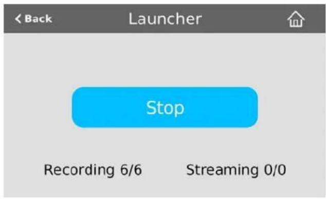
In the example above, One Touch control has been activated and all six out of the six total channels and/or recorders are recording successfully. There is no streaming activity because there are no channels configured for One Touch streaming.
If there is a problem with your streaming and/or recording settings, an error icon will display after pressing the Start button. Note that recordings and streams without problems will continue to function normally.
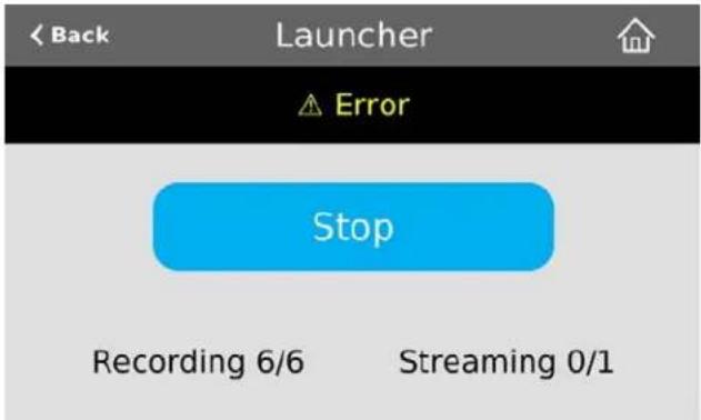
In the example above, after pressing Start, all six recorders/channels are recording properly but the one channel configured for streaming is not streaming correctly!
If you have multiple channels configured for streaming and more than one of these channels is not streaming correctly, navigate to each channel's streaming configuration page in the Admin panel to identify the channel(s) in question and correct streaming configuration errors.
If you encounter an error such as this one, we recommend you verify your streaming/recording settings for your specified channels. See Specify channels for One Touch streaming and Specify channels and recorders for One Touch recording for more information on configuring channels and recorders for One Touch control.
Specify channels and recorders for One Touch recording
All channels and recorders are enabled for One Touch recording by default; however you can choose to exclude individual channels and recorders.
Topics include:
- Specify channels for One Touch recording
- Specify recorders for One Touch recording
Specify channels for One Touch recording
You can use the Admin panel to enable or disable each channel for One Touch recording control. (See Record to learn how to configure your channels for recording).
To specify channels for single touch recording:
- Login to the Admin panel as admin. See Connect to the Admin panel.
- Click the name of the selected channel to expand the channel menu.
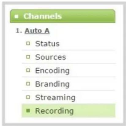
- Click the Recording link to open the channel's Recording page.
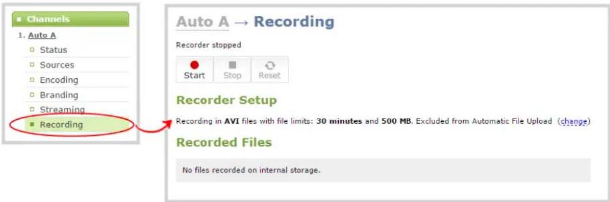
- Click the change link next to the text "Excluded from Automatic File Upload" to display additional recording setup options.

- Select (or deselect) the Single touch control checkbox to enable or disable One Touch control for the current channel.
- Click Apply to save your changes.
Specify recorders for One Touch recording
You can use the Admin panel to enable or disable each recorder for One Touch recording control. (See Recorders to learn how to configure recorders for your Pearl-2.)
To specify recorders for One Touch recording:
- Login to the Admin panel as admin. See Connect to the Admin panel.
- Click the name of the selected recorder under the Recorders heading to display the Recorder Setup page.
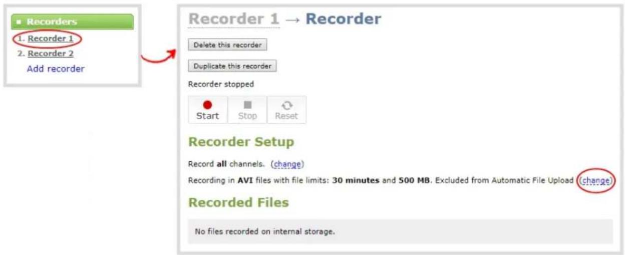
- Click the change link next to the text "Excluded from Automatic File Upload" to display additional recording setup options.
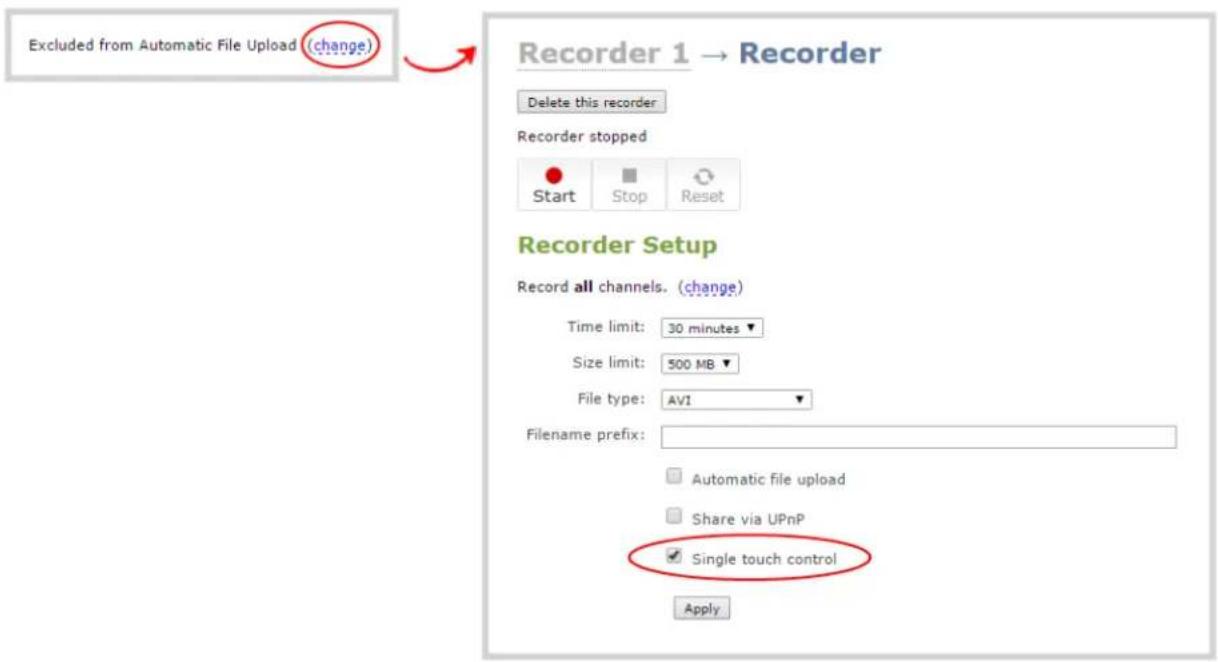
- Select (or deselect) the Single touch control checkbox to enable or disable One Touch control for the current channel.
- Click Apply to save your changes.
Specify channels for One Touch streaming
One Touch control allows you to set channels for streaming, however channels are not enabled for One Touch streaming by default. (See Stream to learn how to configure your channels for streaming.)
To specify channels for One Touch streaming:
- Login to the Admin panel as admin. See Connect to the Admin panel.
- Click the name of the selected channel to expand the channel menu.
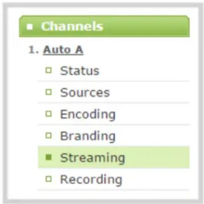
- Click the Streaming link to open the channel's Streaming page.
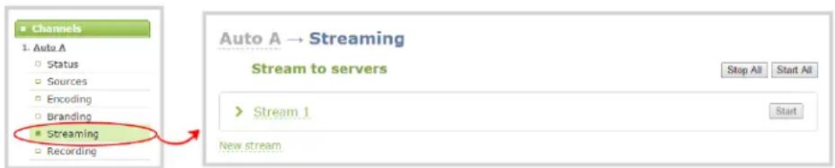
- Click the New stream drop down menu and select your desired publish method.

- Select (or deselect) the Single touch control checkbox to enable or disable One Touch control for the current channel.
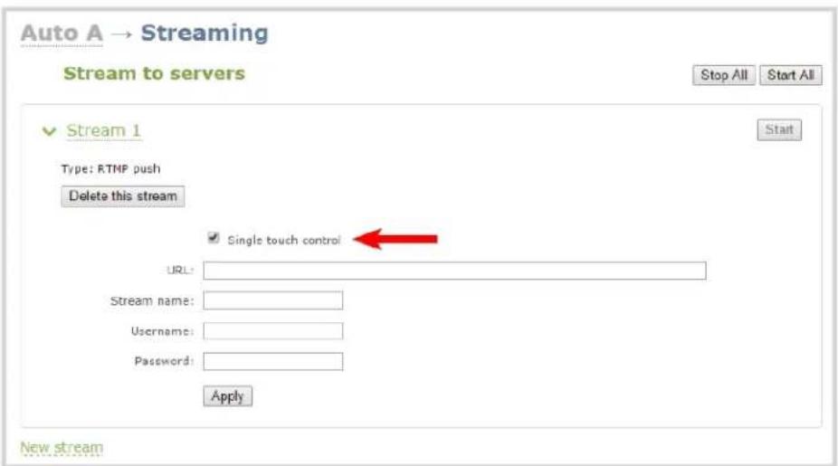
- Click Apply to save your changes.
Customize how One Touch control is displayed
Using Pearl-2's Admin panel, you can customize how the One Touch control screen displays. For example, you can configure the One Touch control screen to display on system startup and/or lock the screen to prevent Pearl-2 operators from navigating elsewhere using the touch screen.
You can customize how One Touch Control is displayed using the following settings:
Default: The One Touch control screen can be accessed by touching the One Touch control icon at the bottom of Pearl-2's touch screen.
Start Screen: The One Touch control screen displays upon system startup. Operators are still free to navigate to other screens (i.e. preview screen, settings).
Locked: The One Touch control screen is the only view available; operators are prevented from navigating to different screens.
To select how Pearl-2 displays the One Touch control screen:
- Login to the Admin panel as admin. See Connect to the Admin panel.
- Click the Touch Screen link under the Configuration heading; the touch screen configuration opens.

-
Click the Single touch control dropdown menu and select Default, Start Screen or Locked.
-
Click Apply; your One Touch control display settings are now saved. If you chose to apply Start Screen or Locked, your Pearl-2's touch screen will automatically refresh to display the One Touch control screen.
View AFU status
You can view basic Automatic File Upload (AFU) information from your Pearl-2's touch screen.

See File and recording transfer to learn how to configure AFU settings in the Admin panel.
Table 21 AFU status touch screen components
| Label | Name Description |
| 1 Status | |
| 2 Protocol | |
| 3 Queue |
To access the Automatic File Upload status in the touch screen:
- Touch the system settings button (the gear icon) in the lower right corner of the screen.
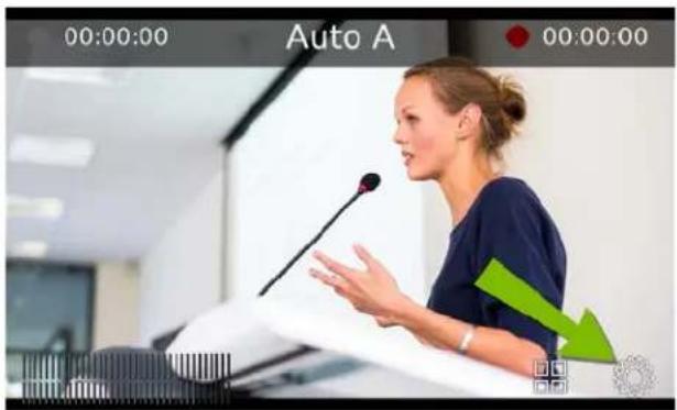

If the gear icon is not visible on the touch screen, tap the screen once to activate the control buttons. If the system settings button is still not visible, it is disabled in the system's touch screen configuration. See Configure the touch screen to enable system information.
- Touch the arrow icon in the lower-right corner of the screen to naviget to the second Settings page.

- Touch Automatic File Upload to display the AFU Status page.
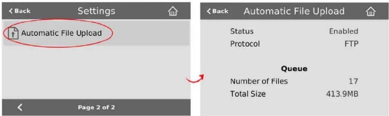
To close the system information screen, touch Back (in the upper-left corner of the screen) to return to the System Settings view, or the Home icon to return to the channel view.
Configure the touch screen
By default, Pearl-2's touch screen is enabled and all its features are available. Depending on your circumstances, you may wish to disable the screen, or disable just some of its features.
This section covers the following touch screen configuration items:
- Disable (or enable) the touch screen
- Hide (or show) channel previews on the touch screen
- Disable (or enable) system status on the touch screen
• Block (or allow) configuration functions from the touch screen
• Block (or allow) recording, streaming and switching from the touch screen - Set touch screen timeout
- Configure touch screen PIN security code
Disable (or enable) the touch screen
You can prevent Pearl-2 from displaying anything on the touch screen, or you can re-instate this feature by toggling the Enable display configuration option.

The display is always touch-sensitive. This control indicates whether or not the display is on or off.
To disable (or enable) the touch screen display:
-
Login to the Admin panel as admin. See Connect to the Admin panel.
-
Select the Touch Screen link in the Configuration menu; the touch screen configuration page opens.

- Uncheck Enable display to disable the display (or check the box to enable the display).
- Click Apply.
Hide (or show) channel previews on the touch screen
By default, Pearl-2 shows previews of each configured channel. If this isn't suitable for your needs, you may disable channel preview. When channel previews are disabled, the touch screen shows the following image:
Preview is disabled

Check your device settings

While preview is disabled, if system status or settings and configuration preset changes are permitted, you can touch the screen anywhere to open the settings page.
To hide (or show) the channel previews on the touch screen:
- Login to the Admin panel as admin. See Connect to the Admin panel.
- Select the Touch Screen link in the Configuration menu; the touch screen configuration page opens.
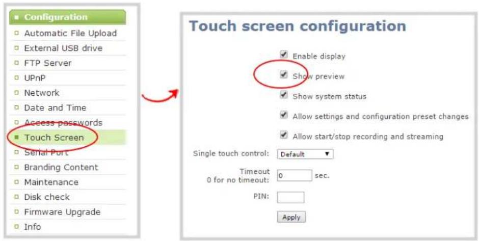
- Uncheck Show preview to disable channel previews (or check the box to enable previews).
- Click Apply.
Disable (or enable) system status on the touch screen
Once you've configured, Pearl-2 it's possible you may no longer wish to show the system status screen on the touch screen.
To hide (or show) system information on the touch screen:
- Login to the Admin panel as admin. See Connect to the Admin panel.
- Select the Touch Screen link in the Configuration menu; the touch screen configuration page opens.
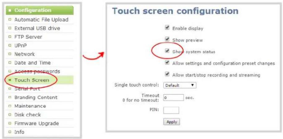
- Uncheck Show system status to prevent the system status screen from being accessible on the touch screen (or check the box to enable system information).
4. Click Apply.
Block (or allow) configuration functions from the touch screen
By default, Pearl-2 permits applying configuration presets and configuring network settings via the touch screen. You can disable this ability.

If configuration is blocked and system status is permitted, touch screen users see an i icon instead of the configuration gears icon in the lower right corner of the touch screen.
To block (or allow) the channel previews on the touch screen:
- Login to the Admin panel as admin. See Connect to the Admin panel.
- Select the Touch Screen link in the Configuration menu; the touch screen configuration page opens.

-
Uncheck Allow settings and configuration preset changes to disable configuration from the touch screen (or check the box to enable configuration).
-
Click Apply.
Block (or allow) recording, streaming and switching from the touch screen
By default, Pearl-2 permits recording, streaming and live switching control for individual channels. You can disable this control to prevent unwanted interruptions in streaming, gaps in recordings or to stop users from switching the layout used.

Channel preview must be on for recording, streaming and live switching control to work.
To block (or allow) the recording, streaming and live mixing / switching control via the touch screen:
- Login to the Admin panel as admin. See Connect to the Admin panel.
- Select the Touch Screen link in the Configuration menu; the touch screen configuration page opens.
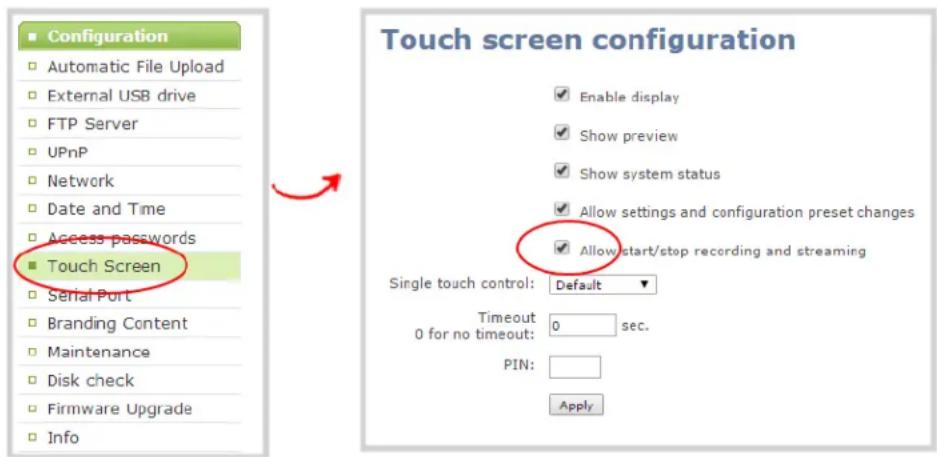
- Uncheck Allow start/stop recording and streaming to disable recording, streaming and live switching control from the touch screen (or check the box to enable control).
- Click Apply.
Set touch screen timeout
Initially, the touch screen is always on for easy monitoring. However, if you'd like, you can modify its configuration to cause it to shut off after a given amount of time. To re-enable it after timeout, simply touch anywhere on the screen.
To set a timeout for the touch screen:
- Login to the Admin panel as admin. See Connect to the Admin panel.
- Select the Touch Screen link in the Configuration menu; the touch screen configuration page opens.
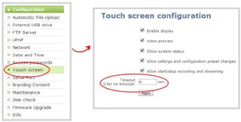
-
Enter a value in the Timeout field. The value is in seconds. Use 0 to keep the screen on whenever the system is on.
-
Click Apply.
Configure touch screen PIN security code
You can configure a 4-digit PIN code to protect your Pearl-2's touch screen from unauthorized access. By default, the PIN is not set.
If a PIN is configured, the user is prompted to enter the code in the following scenarios:
- When Pearl-2 is powered on, or restarts,
- When Pearl-2 recovers from timeout mode (see Set touch screen timeout).

To configure a 4-digit PIN code:
- Login to the Admin panel as admin. See Connect to the Admin panel.
- Select the Touch Screen link in the Configuration menu; the touch screen configuration page opens.
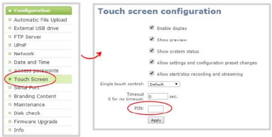
- Enter your desired 4-digit PIN code in the PIN field
- Click Apply to set your PIN.
View system information
The system information page provides a great deal of useful information about your Pearl-2. Use the Info link from the Configuration menu to view your current firmware level, system hardware version (if available) and currently configured channels.
To view system information:
- Login to the Admin panel as admin. See Connect to the Admin panel.
- From the Admin panel scroll to the Configuration menu option.
- Click Info; the system information page opens.
| Pearl-2 B7E5C813 info | |||||||||||
| Firmware | |||||||||||
| Version: 4.0.0cRevision: 15719_1771Date: 2016-08-22 | |||||||||||
| Hardware | |||||||||||
| CPU board: SKYBAY (Default string) | |||||||||||
| Channels | |||||||||||
| # | Channel name | Status | Video source | Audio source | Stream | Bitrate | Actual bitrate | Frame size | FPS / Actual FPS | Port | |
| 1 | HDMI-A | ok | HDMI-A | HDMI-A Audio | H.264+PCM | auto | 1621 kbps | 1920x1080 | 30/30.0 | 8000 | View |
| 2 | HDMI-B | ok | HDMI-B | HDMI-B Audio | H.264+PCM | auto | 1615 kbps | 1920x1080 | 30/30.0 | 8001 | View |
| 3 | HDMI4K-A | ok | HDMI4K-A | HDMI4K-A Audio | H.264+PCM | auto | 1617 kbps | 1920x1080 | 30/30.0 | 8002 | View |
| 4 | HDMI4K-B | no signal | HDMI4K-B | HDMI4K-B Audio | H.264+PCM | auto | 3578 kbps | 1920x1080 | 30/30.0 | 8003 | View |
| 5 | SDI4K-A | no signal | SDI4K-A | SDI4K-A Audio | H.264+PCM | auto | 1599 kbps | 1920x1080 | 30/24.8 | 8004 | View |
| 6 | SDI4K-B | no signal | SDI4K-B | SDI4K-B Audio | H.264+PCM | auto | 1642 kbps | 1920x1080 | 30/30.0 | 8005 | View |
| Overall system load: 20% | |||||||||||
- Use the information displayed to get an overview of your system, troubleshoot problems or view streams for configured channels.
Feature add-ons
Pearl-2 hardware provides many useful new features and with more to come. From the common base model of Pearl-2, you can add feature add-ons for extra functionality.
For an overview of add-ons, see:
- Add-ons overview
This section also covers the following related topics:
- Checking availability of add-ons
• Current list of add-ons
• Activate purchased add-ons
• Purchase and install add-ons

Throughout the manual, there is information that applies only when your system has the 4K feature add-on, as indicated with this symbol: ^1 . Wherever that symbol appears, it denotes that the feature is available only if you have activated the 4K feature add-on for your Pearl-2.
Add-ons overview
Pearl-2 add-ons are found in the under the Firmware upgrade page in the Pearl-2 Admin panel.
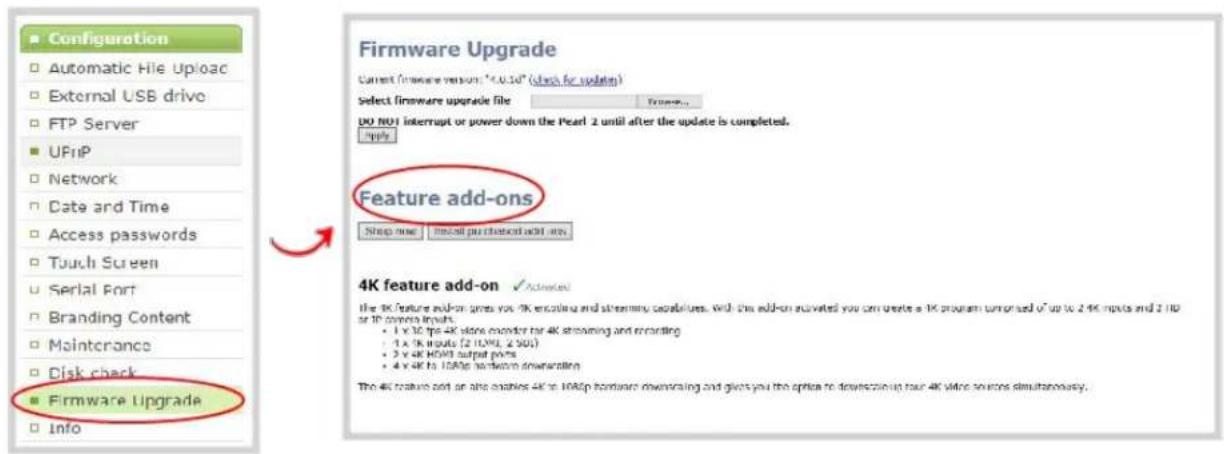
The Feature add-ons section allows for several different functions.
Shop now
The Shop now button leads to the epiphan.com add-ons store page, where you are able to select and purchase any available add-on.
Firmware Upgrade
Current firmware version: "4.0.1d" (check for updates)
Select firmware upgrade file
Browse...
DO NOT interrupt or power down the Pearl-2 until after the update is completed. Apply
Feature add-ons
Shop now
Install purchased add-ons
Install purchased add-ons
The Install purchased add-ons button searches for all purchased add-ons and begins the Activate purchased add-ons installation process for each of them. Since rebooting the system is necessary for the feature activation to occur, the Install purchased add-ons button gives you the option of restarting the system immediately, or later.
Feature add-ons
Shop now
Install purchased add-ons
4K feature add-on
Purchase
The 4K feature add-on gives you 4K encoding and streaming capabilities. With this add-on activated you can create a 4K program comprised of up to 2.4K inputs and 2 HD or IP camera inputs.
- 1 x 30 fps 4K video encoder for 4K streaming and recording
- 4×4K inputs (2 HDMI, 2 SDI)
- 2 x 4K HDMI output ports
- 4 x 4K to 1080p hardware downscaling
The 4K feature add-on also enables 4K to 1080p hardware downscaling and gives you the option to downscale up four 4K video sources simultaneously.
List of features
The Current list of add-ons includes the name of each feature and a detailed description of the capability gained by activating that feature.
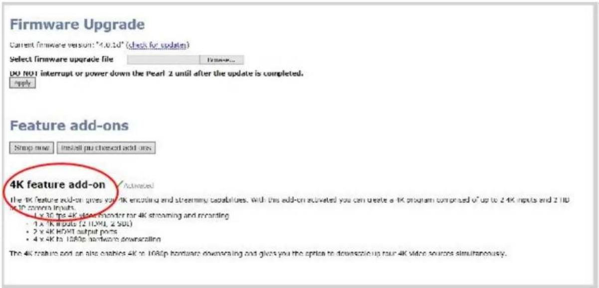
Purchase button
The Purchase button next to a feature leads to the epiphan.com purchase page for that feature. The button remains next to the feature, even after the feature is purchased, until the feature is activated.

Activation indicator
After a feature is purchased and installed, and the system is rebooted, the Activated indicator appears next to the feature description. This indicates that the feature is active, and you are able to use all the functionality described under that feature.

Checking availability of add-ons
It is important to discover quickly and easily which add-ons on your Pearl-2 system are available for purchase, activation or use.
Available for purchase
You can discover which add-ons are available for purchase by using this process:
- Navigate to the Firmware upgrade page.
- Look at all the current possible add-ons are listed on this page under Feature add-ons.
- Any feature available for you to purchase has a button next to it that reads Purchase.
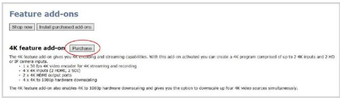
- In order to purchase and activate the feature, follow the instructions at Purchase and install add-ons.
- Even if you have already purchased a feature, the Purchase button remains next to the feature. To determine if a feature with a Purchase button next to it has already been purchased, use the Install purchased add-ons button.
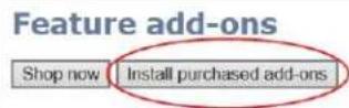
4K feature add-on Purchase
The 4K feature add-on gives you 4K encoding and streaming capabilities. With this add-on activated you can create a 4K program comprised of up to 2.4K inputs and 2 HD or IP camera inputs.
- 1 x 30 fps 4K video encoder for 4K streaming and recording
- 4 x 4K inputs (2 HDMI, 2 SDI)
- 2 x 4K HDMI output ports
- 4 x 4K to 1080p hardware downscaling
The 4K feature add-on also enables 4K to 1080p hardware downscaling and gives you the option to downscale up four 4K video sources simultaneously.
- If there are available add-ons, that have already been purchased, they begin the installation and activation process, detailed at Activate purchased add-ons.
- If there are no available add-ons, the message box informs you. This indicates that all features with a purchase button are available for purchase.
Firmware Upgrade
Current firmware version: "4.0.1d" (check for updates)
Select firmware upgrade file
Bruxide...
DO NOT interrupt or power down the Pearl-2 until after the update is completed.
Apply
Feature add-ons
Shop now
Install purchased add-ons
4K feature add-on √ Activated
The 4K feature add-on gives you 4K encoding and store or IP camera inputs.
- 1 x 30 fps 4K video encoder for 4K streaming and recording
- 4 x 4K inputs (2 HDMI, 2 SDI)
- 2 x 4K HDMI output ports
- 4 x 4K to 1089p hardware downscaling
The 4K feature add-on also enables 4K to 1080p hardware downscaling and gives you the option to downscale up four-4K video sources simultaneously.
×
This site says...
You have no new purchased add-ons
OK
nised of up to 2.4K inputs and 2 HD
- In order to purchase and activate the feature, follow the instructions at Purchase and install add-ons.
Available for installation and activation
You can discover which add-ons are available for installation and activation by using this process:
- Navigate to the Firmware upgrade page.
- Look at all the current possible add-ons listed on this page under Feature add-ons.
- Even if you have already purchased a feature, the Purchase button remains next to the feature. Check if you have any add-on available to install using the Install purchased add-ons button.

4K feature add-on Purchase
The 4K feature add-on gives you 4K encoding and streaming capabilities. With this add-on activated you can create a 4K program comprised of up to 2.4K inputs and 2 HD or IP camera inputs.
- 1 x 30 fps 4K video encoder for 4K streaming and recording
- 4 x 4K inputs (2 HDMI, 2 SDI)
- 2 x 4K HDMI output ports
- 4 x 4K to 1080p hardware downscaling
The 4K feature add-on also enables 4K to 1080p hardware downscaling and gives you the option to downscale up four 4K video sources simultaneously.
- If there are available add-ons, they begin the installation and activation process, detailed at Activate purchased add-ons.
- If there are no available add-ons, the message box informs you.
Firmware Upgrade
Current firmware version: "4.0.1d" (check for updates)
Select firmware upgrade file
Broussie...
DO NOT interrupt or power down the Pearl-2 until after the update is completed.
Apply
Feature add-ons
Shop now
install purchased add-ons
4K feature add-on
√ Activated
The 4K feature add-on gives you 4K encoding and store or IP camera inputs.
- 1 x 30 fps 4K video encoder for 4K streaming and recording
- 4 × 4K inputs (2 HDMI, 2 SDI)
- 2 x 4K HDMI output ports
- 4 x 4K to 1080p hardware downscaling
The 4K feature add-on also enables 4K to 1080p hardware downscaling and gives you the option to downscale up four 4K video sources simultaneously.
- In order to purchase and activate a desired feature, follow the instructions at Purchase and install add-ons.
Available for use
You can discover which add-ons are available for use through this process:
- Navigate to the Firmware upgrade page.
-
Look at all the current possible add-ons listed on this page under Feature add-ons.
-
Any feature available for you to use has text next to it that reads Activated.
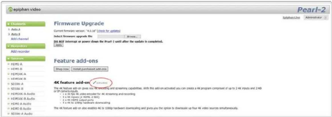
- When this indicator appears, you can use all the abilities of that feature. You can learn what those are by looking at our Current list of add-ons.
Current list of add-ons
As of firmware 4.0.1, the 4K feature add-on is the only add on available for Pearl-2.
4K feature add-on
If you have the base model of Pearl-2, you can add the 4K feature add-on.
The base model of Pearl-2 supports:
- Six simultaneous full HD video inputs (4 x HDMI and 2 x 3G-SDI)
- 6 x 1080p 30 fps encoding (or equivalent)
• XLR and RCA audio inputs with built-in attenuation
The 4K feature add-on gives you access to the base model features, plus:
• 4 x 4K video inputs (2 x 4K HDMI and 2 X 4K SDI)
- 4 x 4K hardware scaling (4K down to full HD)
• 2 x 4K video outputs (HDMI)
• 1 x 4K video encoding
You can find more details on the add-on, along with installation instructions and the add-on itself, at www.epiphan.com/add-ons.

Activating your 4K add-on might not be necessary, depending on the version of Pearl-2 you purchased. As the first Feature Add-on, the 4K add-on was included automatically in some systems. If you purchased the full version of Pearl-2 or an early copy with firmware 4.0.0, the 4K add-on was included with your purchase and is automatically activated, so in those cases no action is required.
Activate purchased add-ons
Pearl-2 add-ons must be purchased, installed and activated before their features can be used. If you have already purchased an add-on either on our site at epiphan.com/add-ons or by purchasing the full version of Pearl-2, follow these instructions to start using your add-on feature. If you have not purchased an add-on that you wish to install, you may follow the process at Purchase and install add-ons.
- Navigate to the Firmware upgrade page to start the process.
- Under Feature add-ons, click the button Install purchased add-ons.
Feature add-ons
Shop now
Install purchased add-ons
4K feature add-on Purchase
The 4K feature add-on gives you 4K encoding and streaming capabilities. With this add-on activated you can create a 4K program comprised of up to 2.4K inputs and 2 HD or IP camera inputs.
- 1 x 30 fps 4K video encoder for 4K streaming and recording
- 4 x 4K inputs (2 HDMI, 2 SDI)
- 2 x 4K HDMI output ports
- 4 x 4K to 1080p hardware downscaling
The 4K feature add-on also enables 4K to 1080p hardware downscaling and gives you the option to downscale up four 4K video sources simultaneously.
If you have multiple add-ons available to install, this button applies to all of them simultaneously.
- After clicking on Install purchased add-ons, a message box appears. Click OK to install the add-on, and automatically restart Pearl-2. When Pearl-2 reboots, the Add-on feature is activated.

If you click Cancel in the message box, Pearl-2 installs the add-on, but does not reboot. The add-on is not activated until Pearl-2 is rebooted. You can reboot normally, or by using the button in the red box that appears at the top-left of the page.
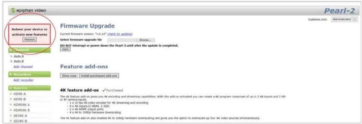
- After you have installed and rebooted your system, you can confirm that the process worked by returning to the Firmware Upgrade page. All activated features indicate that they are activated next to their name.
![epiphan video Pearl-2 Epiphan Live Administrator Firmware Upgrade Current firmware version: "4.0.1d" [check for updates] Select firmware upgrade file Browse... DO BOOT interrupt or power down the Pearl-2 until after the update is completed. Apply Feature add-ons Shop now Install purchased add-ons 4K feature add-on ✓ Add-ons The 4K feature add-on gives you 4K encoding and streaming capabilities, with this add-on activated you can create a 4K program comprised of up to 2.4K inputs and 2 HD or IP camera inputs. • 1 x 30 fps 4K video encoder for 4K streaming and recording • 4 x 4K inputs (2 HDMI, 2 SICI) • 2 x 4K HDMI output ports • 8 x 4K to 138lp hardware downscaling The 4K feature add-on also enables 4K to 108lp hardware downscaling aid gives you the option to downscale up four 4K video sources simultaneously.](/content/2026/06/1365921/images/2d846a32b95fdb8acc1b2b69bbb1a45dab3cb3e0c053170048259a190b92804d.jpg)
If you click Cancel in the message box, Pearl-2 installs the add-on, but does not reboot. The add-on is not activated until Pearl-2 is rebooted. You can reboot normally, or by using the button in the red box that appears at the top-left of the page.

Purchase and install add-ons
Pearl-2 add-ons must be purchased, installed and activated before their features can be used. If you have already purchased an add-on either on our site at epiphan.com/add-ons or by purchasing the full version of Pearl-2, follow instructions at Activate purchased add-ons to start using your add-on feature. If you have not purchased an add-on that you wish to install, follow the process outlined below.
- Navigate to the Firmware upgrade page to start the process.
- To select an add-on to purchase, you can navigate directly to the Epiphan site at epiphan.com/add-ons, or use the Shop now button on the Pearl-2 Admin panel under the Feature add-ons section.

Alternatively, you can use the Purchase button next to a specific add-on. This directs you to that feature's purchase page on the epiphan.com site. Note that for Pearl-2 Rackmount Twin, you only purchase one instance of the add-on, but you are required to complete the activation process for each system in the Pearl Rackmount Twin.

- Once you have purchased the Add-on, you must install and activate it before you can use its functionality. Use the button at the top, Install purchased add-ons, to start the installation and activation process.

If you have multiple add-ons to install, this button applies to all of them simultaneously.
- After clicking on Install purchased add-ons, a message box appears. Click OK to install the add-on, and automatically restart Pearl-2. When Pearl-2 reboots, the Add-on feature is activated.

If you click Cancel in the message box, Pearl-2 installs the add-on, but does not reboot. The add-on is not activated until Pearl-2 is rebooted. You can reboot normally, or by using the button in the red box that appears at the top-left of the page.
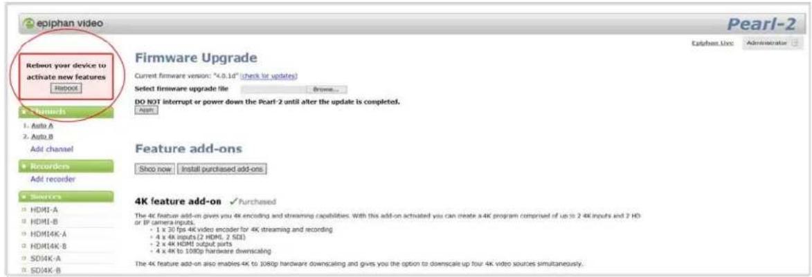
- After you have installed and rebooted your system, you can confirm that the process worked by returning to the Firmware Upgrade page. All activated features indicate that they are activated next to their name.

If you have multiple add-ons available to install, this button applies to all of them simultaneously.
Configure network settings
By default Pearl-2 uses DHCP to obtain an IP Address via an Ethernet-based network. If you want to change the network settings, or if you're having network-related issues, this section covers the network-related topics.
- Verify IP Address and MAC address via the touch screen
- Verify IP address and MAC address via the Admin panel
- Configure a static IP address
- Configure DHCP
• Tether to a mobile network
• Network ports used by Pearl-2
• Perform network diagnostics
Verify IP Address and MAC address via the touch screen
Pearl-2's touch screen interface, if enabled, can quickly and easily show you the system's IP Address and MAC address.
To show system information on the touch screen:
- If the system settings button (gears) does not appear on the screen, tap the screen once to turn on the control buttons (from the "no channels" or "preview disabled" screen, this will go directly to the system settings screen).
- If the system settings button (gears) is still not visible and an i icon is visible instead, configuration by touch screen is disabled in the system's settings. See Configure the touch screen to enable.
- Touch the system settings button (gears) on the screen; the system settings screen appears.
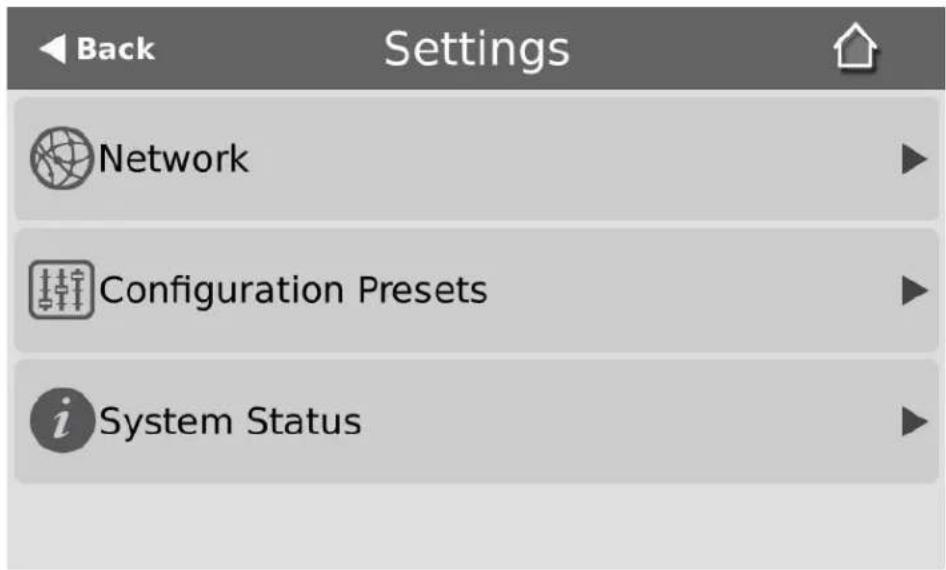
- Touch System Status to see the system information page.
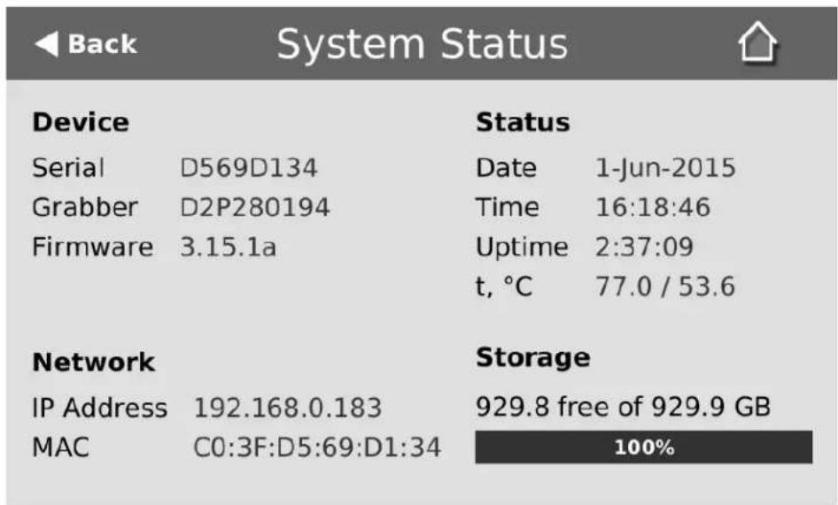
To close the system information screen:
- Touch Back to return to the Systems Settings screen or the Home icon to return to the channel view.
Verify IP address and MAC address via the Admin panel
The Admin panel shows you the system's MAC address and current IP Address via the Network configuration page.
To view settings on network configuration page:
- Login to the Admin panel as admin. See Connect to the Admin panel.
- Select the Network link in the Configuration menu; the network configuration page opens.
- Note the MAC address and Current IP address listed at the top of the page.
IP Configuration for eth0
MAC address is 00:55:56:55:52:5f
Current IP address is 192.168.1.208
Table 22 Network Information Fields
| Label Description/Options | |
| MAC Address | A media access control address (MAC address) is a unique identifier for the network interface. The value is read-only and cannot be changed. You may need to share this value with your system administrator. |
| Current IP Address | Reflects the current internet protocol address (IP address) of the system. This value is either obtained from the DHCP server (if using DHCP) or is the configured static IP address. Pearl-2 supports IPv4 addresses. It does not support IPv6 addresses. |
Configure DHCP
Occasionally, such as when moving your system to a new network, your Pearl-2 must switch from static IP address allocation to dynamic allocation via DHCP. You can accomplish this in four ways:
- Restore factory settings, clearing all your custom settings. See Perform factory reset.
- Load a configuration preset file that uses DHCP networking. See Apply a configuration preset from the Admin panel or Apply a configuration preset using the touch screen.
- Change the network settings. See the procedure below.
For quick and easy setup of Pearl-2, you can configure network settings via the Admin panel or via touch screen.
Using the touch screen, you can choose to apply a configuration preset that uses DHCP (see Configuration presets).
To configure network settings via the touch screen:
- If the system settings button (gears) does not appear on the screen, tap the screen once to turn on the control buttons (from the "no channels" or "preview disabled" screen, this will go directly to the system settings screen).
- If the system settings button (gears) is still not visible and an i icon is visible instead, configuration by touch screen is disabled in the system's settings. See Configure the touch screen to enable.
- Touch the system settings button (gears) on the screen; the system settings screen appears.
- Touch Network; the Network settings page appears. The currently enabled type of network setting (DHCP or static) is highlighted green.
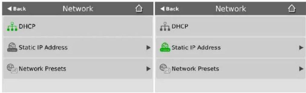
- If not already using DHCP, touch DHCP to enable DHCP.
- If DHCP was not the active network type, a confirmation message is displayed.

- Touch OK; DHCP is enabled.
To configure use of DHCP for networking:
- Login to the Admin panel as admin. See Connect to the Admin panel.
- Select the Network link in the Configuration menu; the network configuration page opens.
- Select the radio button use DHCP, if not already selected.
- Change the MTU Size value only if needed. See the table below for information on maximum transmission unit (MTU) values.
- Click Apply to save the changes; the changes are saved and a message appears asking you to reboot.
Network configuration settings updated. New settings will be applied after reboot.
-
Select the Maintenance link under the Configuration menu; the maintenance page appears.
-
Click the Reboot Now button near the bottom of the page.
-
Wait for the system to reboot.
-
Connect to the Admin panel using your preferred connection mechanism. See Connect to the Admin panel.
-
Log as admin and reload the Networking page to verify all changes were applied.
The following table describes the fields applicable when configuring DHCP on Pearl-2.
Table 23 DHCP Fields
| Label Description/Options | |
| Use DHCP Select this radio button to dynamically obtain an IP address at boot up. | |
| Use static address | Select this radio button to use the configured static IP address. |
| MTU Size | The maximum transmission unit (MTU) specifies the maximum packet size for transfer on the network. The default value is 1500, which is the largest value allowed by Ethernet at the network layer. It's best if all nodes in your network use the same value, so only change this value if you know other nodes use a different value. |
Configure a static IP address
Your network administrator may require you to use a static IP address for your Pearl-2.
For quick and easy setup of Pearl-2, you can configure network settings via the Admin panel or via touch screen.
Using the touch screen, you can choose to apply a configuration presets that contains a static network IP (see Configuration presets).
To configure network settings via the touch screen:
-
If the system settings button (gears) does not appear on the screen, tap the screen once to turn on the control buttons (from the "no channels" or "preview disabled" screen, this will go directly to the system settings screen).
-
If the system settings button (gears) is still not visible and an i icon is visible instead, configuration by touch screen is disabled in the system's settings. See Configure the touch screen to enable.
- Touch the system settings button (gears) on the screen; the system settings screen appears.
- Touch Network; the network settings page appears. The currently enabled type of network setting (DHCP or static) is highlighted green.

- Touch Static IP Address to configure a static IP address; the static IP configuration page appears.

other
Static IP Address | IP Address | 7 | 8 | 9 | | :--- | :--- | :--- | :--- | | 192 . 168 . 10 . 1 | 7 | 8 | 9 | | Network Mask | 4 | 5 | 6 | | 255 . 255 . 255 . 0 | 4 | 5 | 6 | | Default Gateway | 1 | 2 | 3 | | 0 . 0 . 0 . 0 | 1 | 2 | 3 | | DNS Server | < | 0 | . | | 0 . 0 . 0 . 0 | < | 0 | . |-
Touch an IP Address section (e.g. 192) and type a new value using the keypad.
-
Repeat for all fields in the IP Address and Network Mask.

Only IPv4 addresses are supported.
- Enter the Default Gateway address. If you do not have a default gateway for your network, enter the same static IP address as in the previous step.

The default gateway cannot be left blank. If no default gateway is specified, unexpected behavior occurs.
- Enter the DNS Server address. If you do not have a DNS server, enter the new static IP address of the system.
- Touch Apply to apply the changes.
To configure a static IP address via the Admin panel:
- Login to the Admin panel as admin. See Connect to the Admin panel.
- Select the Network link in the Configuration menu; the network configuration page opens.

- Select the radio button use static address, if not already selected.
- Enter the desired IP Address and Network Mask.

Only IPv4 addresses are supported.
- Enter the Default Gateway address. If you do not have a default gateway for your network, enter the same static IP address as in the previous step.

The default gateway cannot be left blank. If no default gateway is specified, unexpected behavior occurs.
-
Enter the DNS Server address. If you do not have a DNS server, enter the new static IP address of the system.
-
Change the MTU Size value only if needed. See the table below for information on maximum transmission unit (MTU) values.
- Click Apply to save the changes; the changes are saved and a message appears asking you to reboot.
Network configuration settings updated. New settings will be applied after reboot.
-
Select the Maintenance link under the Configuration menu; the maintenance page appears.
-
Click the Reboot Now button near the bottom of the page.
-
Wait for the system to reboot.
-
Open the Admin panel using the new IP address.
-
Log as admin and reload the Networking page to verify all changes were applied.
The following table describes applicable fields when setting a static IP address.
Table 24 Static IP Address Fields
| Label Description/Options | |
| Use DHCP Select this | radio button to dynamically obtain an IP address at boot up. |
| Use static address | Select this radio button to use the configured static IP address. |
| IP Address | The internet protocol address (IP Address) to assign. This value is may be obtained from your system administrator. Pearl-2 supports IPv4 addresses. It does not support IPv6 addresses. |
| Network Mask | Also called the subnet mask, this value denotes a range of IP addresses. This value may be obtained from your system administrator, determined from another computer on the same subnet, or calculated using an online subnet calculator. |
| Default Gateway | The network node that serves as an access point to the rest of the network. This value cannot be blank unless you are using DCHP. Specify the system's IP address if you don't have a default gateway on your network. |
| DNS Server | The domain name system server (DNS server) translates human-readable hostnames into corresponding IP addresses. Specify the system's IP address if you don't have a DNS server on your network. This value cannot be blank unless you are using DHCP. |
| MTU Size | The maximum transmission unit (MTU) specifies the maximum packet size for transfer on the network. The default value is 1500, which is the largest value allowed |
Label Description/Options
by Ethernet at the network layer. It's best if all nodes in your network use the same value, so only change this value if you know other nodes use a different value.
Tether to a mobile network
Pearl-2 supports tethering to a mobile device via USB. Tethered networking can work side-by-side with Ethernet routing and either networking system can be a back-up for the other.

When the system falls over to the backup network type (i.e. from Ethernet to mobile, or vice versa) all streaming sessions with clients or servers directly connected to the system are closed and the clients will need to reconnect. You may need to provide a new stream URL (containing the new IP address) to your viewers. See the channel information page to get the new stream URL.
By contrast, actively published streams are closed and reconnected via the secondary network (mobile or Ethernet) automatically, permitted the required publishing server is accessible from the new network.
To configure tethering to a mobile network:
- Configure the mobile device to allow tethering via USB.
- Connect the mobile device to Pearl-2 with a USB cable.
- Login to the Admin panel as admin. See Connect to the Admin panel.
- Select the Network link in the Configuration menu; the network configuration page opens.
- Click the drop-down box next to Use phone/tablet connection in the USB phone/tablet section; the following choices appear:
Table 25 Mobile Tethering Options
| Label Description/Options | |
| Disabled Specifies that no USB tethering is permitted. | |
| No tethering | Specifies that USB tethering is available for connecting a mobile device as a configuration utility (i.e. using the web browser), but no mobile data is used. |
| Prefer ethernet | When chosen, the system tries to use the Ethernet network first. It switches to use the mobile network (tethering) when the Ethernet network is no longer available. To prevent viewer interruptions, mobile data will continue to be used until the mobile network is down or publishing is restarted. |
| Prefer tethering | When chosen, the system tries to use the mobile network (tethering) first. It switches to use Ethernet (hard-wired) when the mobile network is no longer available. To prevent viewer interruptions, Ethernet data will continue to be used until the Ethernet network is down or publishing is restarted.Select this setting if you only have a mobile network. |
- Select your choice based on the table above.
- Click Apply.
Network ports used by Pearl-2
The following is a list of incoming network ports used by your Pearl-2 system. Depending on the services you are using, you will need to make sure your firewall permits traffic over the relevant ports.

The port numbers listed below are the default faults for these services. In many cases, you can use the Admin panel to change the port used for this service.
| Port (or range) Protocol Description | ||
| 21 TCP FTP server, if enabled. See Local FTP server. | ||
| 22 TCP SSH for remote support. See Configure remote support. | ||
| 80 TCP | HTTP for the Admin panel, HLS streaming if enabled. See Stream content using HLS (HTTP Live Streaming). | |
| 123 TCP/UDP | NTP server, if enabled. See Configure synchronized time (NTP, PTP v1 and RDATE). | |
| 319 and 320 UDP | PTP server, if enabled. See Configure synchronized time (NTP, PTP v1 and RDATE). | |
| 443 TCP HTTPS for the Admin panel, HLS streaming if enabled. | ||
| 554 to 554+(x-1) TCP | For RTSP/TCP and RTSP/HTTP streaming on your network (where x is the number of channels configured). The number of ports used depends on how many channels you have with RTSP streaming enabled. See Stream content using HTTP or RTSP. (Note that client video players choose whether they are using RTSP/TCP, RTSP/HTTP or RTSP/UDP).Ports 554 and 555 are also used for internal communications. If streaming is disabled, these ports remain open but refuse all external connection requests. | |
| Random in range 32768 - 61000 | UDP | If the client video player chooses RTSP/UDP, it will negotiate 4 random UDP ports (two for audio and two for video). The port range is dependent on the OS of the client video player and can change with updates to that OS. |
| 1900 UDP | UPnP server (for UPnP discovery), if enabled. See Stream content using UPnP. | |
| Random in range 50000 to 65000 | TCP | UPnP media server, if enabled. Each time the UPnP server is started, a random TCP port in this range is used to enable connections with other UPnP devices. |
| 5353 | UDP | For multicast DNS discovery. Connect via DNS-based service discovery. |
| 8000 to 8000+(x-1) TCP | For Flash and MPEG-TS streaming on your network (where x is the number of channels configured). The number of ports used depends on how many channels you have with streaming enabled. See Stream content using HTTP or RTSP. Ports 8000 and 8001 are also used for internal communications. If streaming is disabled, these ports remain open but refuse all external connection requests. | |
In addition to the ports listed above, there are also outgoing connections as follows:
• for publishing (Stream to a server) - actual ports used is dependant on the server and protocol
- for File and recording transfer - actual ports used is dependant on your configuration
- remote support (when in use) - port 30 see Configure remote support
- firmware update (checks and downloads) - port 80
Perform network diagnostics
If your Pearl-2 has network trouble, you can perform basic network troubleshooting tasks from the Network configuration page. In addition to providing the system's IP address and MAC address to your network administrator, you can also ping an IP address or use traceroute to determine the path taken to an address.

Not all networks support ping and traceroute.
To ping or traceroute an IP address:
- Login to the Admin panel as admin. See Connect to the Admin panel.
- Select the Network link in the Configuration menu; the network configuration page opens.
Network Diagnostics
Address:
ping
traceroute
- Enter your IP address into the Address field.
- Click ping or traceroute; an animation appears to the left of the address to indicate processing is underway.
- Upon completion of the command, read the results from the console-like display is shown below the Network Diagnostics setting.
Network Diagnostics
Address: 192.168.1.104 ping traceroute
<h1 id="ping-w-10-c-4-1921681104">ping -w 10 -c 4 '192.168.1.104'</h1>
PING 192.168.1.104 (192.168.1.104): 56 data bytes=
64 bytes from 192.168.1.104: seq=0 ttl=128 time=1.006 ms=
64 bytes from 192.168.1.104: seq=1 ttl=128 time=0.621 ms=
64 bytes from 192.168.1.104: seq=2 ttl=128 time=0.709 ms=
64 bytes from 192.168.1.104: seq=3 ttl=128 time=0.656 ms=
---
--- 192.168.1.104 ping statistics ---=
4 packets transmitted, 4 packets received, 0% packet loss=
round-trip min/avg/max = 0.621/0.748/1.006 ms=
Configuration presets
Configuration presets are the perfect solution for backing up your system configuration, for situations where you have changing configuration requirements for your Pearl-2 or when you are managing a number of systems and you want them to have similar configurations.
For an overview of configuration presets, see:
- Configuration presets overview
This section also covers the following related topics:
- Configuration groups
• Create a configuration preset - Export and import configuration presets
- Apply a configuration preset from the Admin panel
- Apply a configuration preset using the touch screen
- Apply the Factory default configuration preset
- Update a configuration preset
- Delete a configuration preset
There are also some very important configuration preset considerations to review:
- Configuration preset considerations
Configuration presets overview
Configuration presets make it easy to manage a group of Pearl-2 systems or to use your Pearl-2 in a variety of situations without needing to reconfigure it.
Configuration presets divide the system's settings into the following configuration groups. (For a complete list of what is included in each group see Configuration presets overview.)

System Sources Automatic file uploads



Network Channels EDID

Output ports Touch screen

Using the Configuration presets section of the Maintenance page, you can create and save configuration presets using any number and combination of the configuration groups. Mix and match the settings groups saved together to create sets of configuration settings needed for each situation. You also always have a special Factory default configuration preset (which cannot be erased) to help you return to factory configuration without destructively erasing files saved to the system hard drive (see Configuration presets overview
When you are satisfied with the set of configuration items, you can save it, apply it again at a later date and even download it, then log into another Pearl-2 system and apply it there. You can also apply already uploaded configuration presets through the touch screen.
It's important to note that configuration presets are applied over existing settings. They affect only the settings groups included in the preset; all other settings are unaffected. Read the Configuration presets overview section carefully to understand caveats around using configuration presets.
Configuration presets in action
Here's an example of how configuration presets can make it easy to manage a fleet of systems.
Imagine a company is hired to do the following tasks at a big conference:
- Stream and record each conference session with a picture in picture layout that includes identifying information about the presenter in the metadata and the background image for the stream.
- Stream and record the keynote with pre-show content, post-show content and live switching between a number of different layouts during the show.
• Automatically upload backups of the keynote and session recordings.
The company will meet these goals with a fleet of Pearl-2 systems.
Before the show, they upload the required backgrounds and create channel configuration presets for the keynote and each conference track. Each of these is saved as a named preset (for example Keynote, Session 1, Session 2) with all the pieces needed for that session, including the background image(s), metadata, streaming settings, etc.
They also create network and automatic file upload (AFU) presets for each of the home and remote locations.
Once at the conference, they upload these configuration files to the fleet of systems and apply the network and AFU preset. Before each conference session they need only apply the appropriate preset to configure the system correctly for the session. Note that once the presets are loaded on the system you can apply them via the touch screen!

Channel configuration includes background and other image files used. If these files aren't present when the configuration preset is saved, the save function will fail. Be careful when deleting background images and logo files.
Let's take a closer look at the types of presets they make:
Internal network and AFU preset
The company uses this preset when configuring and testing from their corporate network. It uses a static IP address on their corporate network and AFU that uses ftp to upload to a local ftp server.
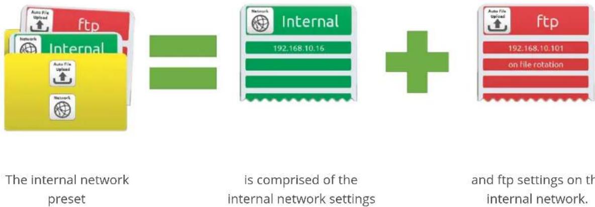
flowchart
graph LR
    A["The internal network preset"] --> B["is comprised of the internal network settings"]
    B --> C["+"]
    C --> D["and ftp settings on the internal network"]
Conference network and AFU preset
The company applies this preset to Pearl-2 systems when they arrive at the conference. It changes only the network and AFU settings (using a conference-specific IP address and secure file transfer to an ftp server).
When applying this configuration preset, all other information including passwords, date/time, channels and source configurations, remains the same.

flowchart
graph LR
    A["The conference network"] --> B["Internet"]
    B --> C["+"]
    C --> D["and an ftp address on conference network"]

    subgraph A
        A1["Auto File Upload"] --> A2["Internet"]
        A3["Auto File Upload"] --> A4["Network"]
    end

    subgraph B
        B1["Network"] --> B2["Internet 104.130.42.89"]
    end

    subgraph C
        C1["+"]
        C2["+"]
    end

    subgraph D
        D1["Auto File Upload"] --> D2["sftp 104.130.42.89:22"]
        D3["on file rotation"]
    end
The conference network preset
Conference breakout session and keynote presets
The company creates one preset per session and one for the keynote. Each preset includes all the files and everything needed to recreate a custom channel configured with the layouts and backgrounds needed for the session.
They upload these presets at the beginning of the conference and apply the correct one prior to each conference session starting. When they apply the preset, all other preset groups remain unchanged; the preset only affects the channel(s) and their configuration. This preset includes a channel the background file and has metadata specifying the speaker's name.

has the presenter data and background image for session 1.
has the presenter data and background image for session 2.
Note that after applying a preset, files from the previous session remain present on the system and continue to upload via sftp (if not yet complete), but the channels reflect the newly loaded session's background file name and presenter name.
Summary
Configuration presets are a versatile tool to help you use Pearl-2 in a variety of conditions. Try it yourself and see!
Configuration groups
The following table describes what settings are saved with each configuration group.
Table 26 Configuration group definitions
| Group Name Symbol Settings included in the configuration group | ||
| System |  | Date and time settings, serial port settings, remote support settings, custom disk check schedule, access passwords, deny/allow lists and LDAP configuration settings. |
| Network Net |  | ngs and tethering configuration. |
| Sources |  | All audio and video source configuration settings (including no signal images) except EDID settings, which are in their own group. |
| Channels |  | All channel configuration data and current recording state, all layouts, images used in layouts, streaming state, all recorder configuration data and current recording state, individual and global UPnP settings. |
| AFU |  | Automatic file upload type and parameters, including SCP/SFTP identity (store in an encrypted form). |
| EDID |  | EDID settings for sources. (Applying configuration presets with this group automatically applies the included EDIDs. This process can take a while.) |
| Output ports A |  | ation settings for the output ports. |
| Touch screen F |  | touch screen use settings. |

Note that SFTP/SCP private keys are included (in encrypted format) in the automatic file upload preset.
Create a configuration preset
You can create as many configuration presets as you need, however there is a limit to the amount of space you have for configuration presets (256 MB). For each configuration preset you create, you get to name the preset and choose the groups of setting types to include. See Configuration groups for more information about the groups of configuration items.
It's good practice, after completing configuration of your Pearl-2, to save a full backup (with all groups selected) so you may restore it at a later date (i.e. after a change that wasn't wanted or after a factory reset).

Note that configuration presets that include network or system settings require a system reboot when applied.
To create a configuration preset:
- Login to the Admin panel as admin. See Connect to the Admin panel.
- Select the Maintenance link in the Configuration menu; the maintenance page opens.
- Scroll to the Configuration presets section.

- Type a description for your preset in the Name field.
- Ensure only the desired configuration groups are selected from the Sections group. (For full system backup, select all groups.)
- Click Save; your configuration preset appears in the list.

If you try to save a configuration preset but one or more of the related image files is missing, you'll see an error. You'll be unable to save the preset until the missing files are restored or the layouts referencing the files are changed to remove the references.

If you try to save a configuration preset but there isn't enough space, you'll see an error message. You'll need to delete some presets before proceeding.

There is a maximum amount of 256 MB available to save configuration presets and a maximum size of 128 MB for a single configuration preset.
Export and import configuration presets
After creating your configuration presets (see Create a configuration preset), you can download the file to your local computer. You can then choose to upload and apply this preset to other Pearl-2 systems or you can store the preset as an offline backup of your current configuration.
Either way, it is a simple two-step process to download the preset from one system and upload it to another.

Uploading a preset does not apply immediately. You must still apply the preset using Apply a configuration preset using the touch screen or Apply a configuration preset using the touch screen.
Download a configuration preset
To download or export a configuration preset:
- Login to the Admin panel as admin. See Connect to the Admin panel.
- Select the Maintenance link in the Configuration menu; the maintenance page opens.
- Scroll to the Configuration presets section.
- Click the Download button next to the configuration preset you wish to export.

- The configuration preset file (with extension .preset) is saved to your admin workstation (in your browser's download folder).
Import a configuration preset
To import a configuration a preset:
- Login to the Admin panel as admin. See Connect to the Admin panel.
- Select the Maintenance link in the Configuration menu; the maintenance page opens.
- Scroll to the Import configuration preset section.
- Click the Choose file button; a file picker window opens.
- Select the file you wish to upload (with the extension .preset) and click OK.
- Click Import.
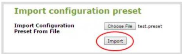
- If your system already has a configuration preset with the same name as the one you're loading, a warning is shown. Choose OK to overwrite the existing preset or Cancel to cancel the upload.

- If the process is not canceled, the configuration preset file is uploaded (but not applied).
- If desired, apply the configuration preset. See Apply a configuration preset from the Admin panel or Apply a configuration preset using the touch screen.
Apply a configuration preset from the Admin panel
When you apply a configuration preset, the system settings for all included configuration groups are updated. Other settings on the system are not affected. For example if you apply a preset that includes the configuration groups channels and automatic file upload, your network settings, passwords, time server, source configurations, etc are not modified. Similarly, if you apply a configuration preset that has only network settings included, only the network settings change.
If you apply a preset that has the network or system configuration group, a reboot is required. If you apply a preset that has the EDID configuration group, the system may appear unresponsive for a short time while it applies these EDIDs to the video grabbers.
You can verify which configuration groups are included in a preset by looking at the list to the right of the configuration preset name. The term 'all' means all groups are included. Otherwise groups are listed individually.

You may apply multiple presets one after another. If you apply two (or more) configuration presets that include a particular configuration group, the settings (for that group) from the last applied preset are the active settings. In short, last in wins.
To apply a configuration preset from the Admin panel:
- Login to the Admin panel as admin. See Connect to the Admin panel.
- Select the Maintenance link in the Configuration menu; the maintenance page opens.
- Scroll to the Configuration presets section.
- Click the Apply button next to the configuration preset you wish to apply.
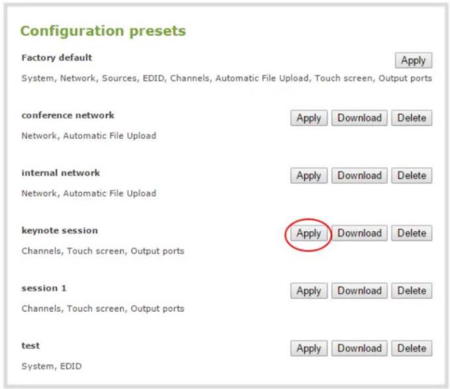
- The system asks for confirmation before proceeding.

If the configuration preset includes the network or system configuration groups, a reboot is necessary.

- Click OK to apply the configuration preset; the configuration preset is applied.
- The system reboots if needed.
Apply a configuration preset using the touch screen
You can use Pearl-2's touch screen to apply configuration presets.
For configuration presets that only contain the network configuration group you can use either of the two methods described below. For all other configuration presets, use the first method.
If you apply a preset that has the EDID configuration group, the system may appear unresponsive for a short time while it applies these EDIDs to the video grabbers.
To apply a configuration preset via the touch screen:
- If necessary, tap the screen once to turn it on or to turn on the screen overlay.
- If the system settings button (gear) is still not visible and an i icon is visible instead, configuration by touch screen is disabled in the system's settings. See Configure the touch screen to enable.
- Touch the gear icon at the bottom right of the screen; the settings page appears.
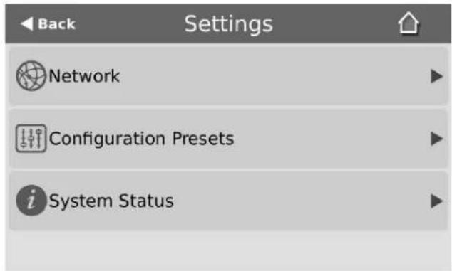
- Touch Configuration Presets; an alphabetically sorted list of saved presets is presented (Factory default is always listed first). Each preset shows the included preset configuration groups via a list of icons to the right of the preset name.
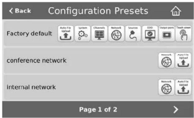
- If necessary touch the arrows at the bottom of the page to navigate to the desired preset.

- Touch the name of the preset you wish to apply.
- A confirmation message is displayed.

If the configuration preset includes the network or system configuration groups, a reboot is necessary.

- Click OK to apply the preset; the configuration preset is applied.
- The system reboots, if required.
To apply a configuration preset that contains only the network configuration group you may use this process:
- If necessary, tap the screen once to turn it on or to turn on the screen overlay.
- Touch the gear icon at the bottom right of the screen; the settings page appears.

- Touch the Network line; the network configuration page opens.

- Touch Network Presets; a list of saved configuration settings with only Network settings opens.

- Touch the name of the preset you wish to apply; a confirmation message is displayed.
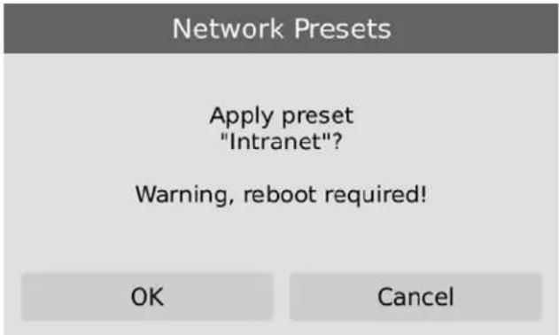
- Click OK to apply the network configuration preset and reboot the system.
Apply the Factory default configuration preset
Your Pearl-2 comes with a special factory default configuration preset. This configuration preset cannot be erased and is always presented at the top of the configuration presets list. It contains all six possible configuration settings groups.
Using the Factory default configuration setting is similar to using the Factory reset method (see Perform factory reset) with a few important differences.
In short, the Factory default configuration preset is less destructive than Factory reset. This table describes the exact differences.
Table 27 Factory default configuration preset vs Factory reset
| Factory default configuration preset | Factory reset function | |
| Deletes all created channels | √ | √ |
| Deletes all recorded files in channels | √ | |
| Deletes all created recorders | √ | √ |
| Deletes all recorded files in recorders | √ | |
| Resets network configuration | √ | √ |
| Resets touch screen configuration | √ | √ |
| Resets user passwords | √ | √ |
| Deletes all created configuration presets | √ | |
| Deletes all branding files | √ | |
| Resets all Source settings | √ | √ |
| Resets EDID to factory | √ | √ |
| Deletes all SCP/SFTP identities | √ | √ |
| Deletes all LDAP settings | √ | √ |
| Deletes all Automatic file upload settings | √ | √ |
To apply the factory default configuration preset, follow the instructions in Apply the Factory default configuration preset or Apply the Factory default configuration preset and select the Factory default preset. A reboot is required.
Update a configuration preset
If you need to update a configuration preset to include different configuration groups, or simply new settings for the same groups, you can do so easily via the Admin panel.
To update a configuration preset:
- Login to the Admin panel as admin. See Connect to the Admin panel.
- Select the Maintenance link in the Configuration menu; the maintenance page opens.
- Scroll to the Configuration presets section.

- Find the preset you wish to change from the presets list.
- Copy the name of the preset into the Name field.
- Selected the desired configuration group(s) from the Sections group.
- Click Save; a confirmation dialog asks you to confirm you want to overwrite the configuration preset.
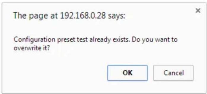
- Click OK; your configuration preset is updated in the list.
Delete a configuration preset
You may want to trim the list of configuration presets to only those that are needed for your ongoing needs. You can delete all configuration presets at once by doing a factory reset, or you can delete individual configuration presets from the Maintenance page.
To delete a configuration preset:
- Login to the Admin panel as admin. See Connect to the Admin panel.
- Select the Maintenance link in the Configuration menu; the maintenance page opens.
- Scroll to the Configuration presets section.
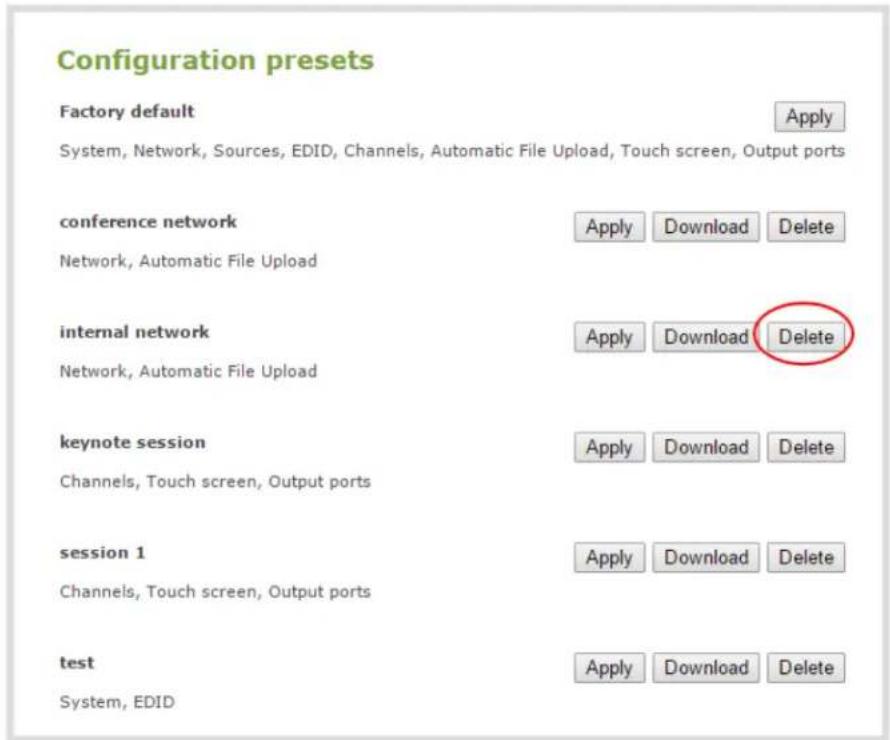
- Click the Delete button for the configuration preset; a confirmation message appears.

- Click OK to confirm you want to delete the preset; the preset is deleted.
Configuration preset considerations
Configuration presets are groups of settings applied to the system, leaving other settings intact. The following considerations will help you get the most from your configuration presets.
Channel and recorder index number behavior
Each channel and recorder has an index number. The first channel created on a system is channel 1, subsequently channel 2, 3, 4, etc. Recorders are also created starting at index 1 with numbers incrementing as new recorders are created. The channel (or recorder) index number is found to the left of the channel or recorder name in the Admin panel:
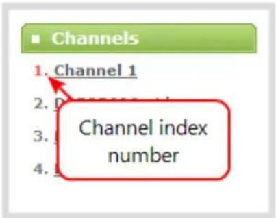
Configuration presets that contain the channels configuration group specify the channels in the preset by their index number. This means if you have channels 1, 2, 3 and 4 when you save your preset, applying that preset will overwrite the configuration of your current channels with indexes 1, 2, 3 and 4. If prior to applying that preset you also had channels with indexes 5 and 6, the configuration settings for those two channels are erased when the preset is applied (because the preset only has 4 channels).
There are three areas where channel (and recorder) index numbers affect what happens when applying configuration presets. Read Recording and streaming statesRecorded files (in channels and recorders) and Deleting channels for more information.
Recording and streaming states
The Configuration groups section of this chapter shows that each channel and recorder's recording and streaming state is included in the channels configuration group. This means that if a channel is streaming or a channel (or recorder) is recording at the time you create a configuration preset, it will immediately start recording (or streaming) when you apply that preset. Similarly, if a configuration preset is saved when channels or recorders are not recording (or streaming), those channels and recorders will not be recording (streaming) when the preset is applied

This means a channel or recorder may stop recording or streaming as a result of applying the preset.
For example, when applying a preset with channel 3 set to record (the same example applies for streaming):
- If channel 3 exists prior to applying the preset and is already recording, the file will continue recording uninterrupted unless the recording file type is different in the preset (in which case a new file is started).
- If channel 3 exists prior to applying the preset and is not already recording, it immediately begins recording.
- If no channel with index 3 exists prior to applying the preset, the channel is created and it immediately begins recording.
Recorded files (in channels and recorders)
Channels and recorders keep a list of files recorded in their Recordings section of the Admin panel. These files remain on the system even if the channel or recorder configuration is changed or removed as a result of applying a configuration preset.
For example, prior to applying your configuration preset, you have channels with indexes 1, 2 and 3; each of these has five recording files. When you apply a configuration preset that has channels with index 1 and 2 only, you'll notice those channels each still have the same 5 recording files. Channel with index 3 is no longer present, but the files are not lost!
Overwritten channel files are still available. To access and download/delete these recorded files, enter the following into the address bar: http://
For example, if a Channel with index 3 is no longer present, its corresponding files can be accessed by entering the following into the address bar:
- http://192.168.0.183/admin/channel3/archive
If you now create a new channel with index 3 (or load a preset that contains a channel with index 3), you'll find it starts with five recorded files in the Recordings section. These are the same recorded files that existed at the start of this example.
Furthermore, if you delete any of the recordings, you are deleting the only instance of those files. Using our previous example, if you delete one of the five recordings from channel index 1, you'll find that even after applying different presets channel 1 will have only four recorded files.
Deleting channels
Recorded files are stored on the system based on their channel or recorder number. All files saved for channel index 1 are in one folder, and all files for recorder index 2 are in another. When you delete a channel (or recorder), you permanently delete all recordings for that channel (or recorder) even if those recordings were made while a different preset is applied.

Applying a configuration preset with a different set of channels or recorders is not the same as deleting a channel.
When deleting a channel or recorder that has recorded files, the Admin panel warns you of other configuration presets that use the same channel or recorder index numbers. When you see this prompt, we recommend you take a moment to look through the Recordings list to make sure you're OK to proceed with permanently deleting all the recorded files.
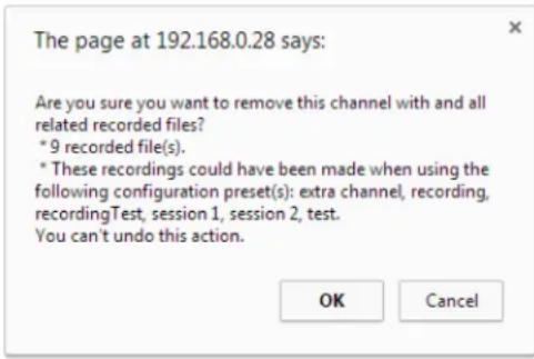
Branding content
Branding content files (logos, background images, etc) are included in your configuration presets and must be present on the system when creating a preset that includes the Channels group, otherwise a failure is reported.
Configuration presets are not user profiles
Configuration presets should not be confused with the concept of user profiles. Specifically, the following issues arise from trying to use configuration presets as user profiles:
- recorded files are not removed between application of configuration presets (users could see each other's files)
- configuration presets can be overwritten and deleted with no password (users could affect each other's presets)
- branding and recorded files can be deleted, affecting more than just the currently applied configuration presets (users could erase branding or recordings belonging to other users)
- applying a configuration presets does not clear the settings from groups not part of the preset (user information is not private)
Touch screen considerations
The touch screen configuration group includes all the security settings for the touch screen. One such setting is the ability to use the touch screen. It is therefore possible to apply a preset via the touch screen that effectively locks out any further use of the touch screen. If this happens accidentally, use the Admin panel to re-enable the touch screen (see Configure the touch screen).
Configure date and time
Pearl-2 uses the current date and time in naming recorded files and when synchronizing and timestamping inputs from multiple sources (i.e. when synchronizing an audio and a video source). The Admin panel lets you specify date and time settings to ensure they are correctly configured for your time zone and your network.
This section covers the following date and time-related topics:
- Verify date and time via the touch screen
- Verify date and time settings
- Change the time zone
- Configure synchronized time (NTP, PTP v1 and RDATE)
- Configure a local NTP server
- Configure the date and time manually
Verify date and time via the touch screen
Pearl-2's touch screen interface, if enabled, can quickly and easily show you the system's date and time settings.
To show system information (including date and time) on the touch screen:
- If the system information button (i) does not appear on the screen, tap the screen once to turn on the control buttons.
- If the system information button (i) is still not visible, it is disabled in the system's Touch screen configuration. See Configure the touch screen to enable system information.
- Touch the system information button (i) on the screen; the system information screen appears.

To close the system information screen:
- Touch anywhere on the screen to return to the previous screen.
Verify date and time settings
The current date, time, time zone, and synchronized time protocol settings are shown when the Date and Time configuration page is loaded in the Pearl-2 Admin panel.
To view settings on the date and time configuration page:
- Login to the Admin panel as admin. See Connect to the Admin panel.
- Select the Date and Time link in the Configuration menu; the date and time configuration page opens and the following information is displayed:
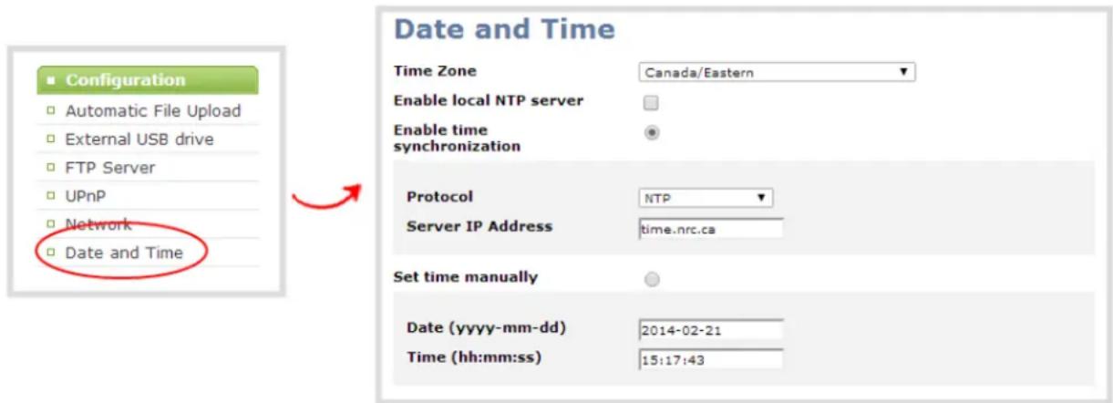
The date and time configuration page also indicates whether the system is currently using synchronized or manually set time, and whether or not a local network time protocol (ntp) server is running.
The following table describes the date and time configuration fields.
Table 28 Date and Time Options
| Label Description/Options | |
| Time Zone The currently selected time zone. | |
| Enable time synchronization | Whether or not a time synchronization protocol is being used for setting time. (If not selected, time is set manually.) |
| Protocol The time synchronization protocol. | |
| Service IP Address | The time synchronization server address. |
| Set time manually | Whether or not time is set manually. (If time is not being set manually, a time synchronization protocol is used.) |
| Date | The current date. (This is the current date even if the radio button Set time manually isnot selected.) |
| Time | The current time. (This is the current time even if the radio button Set time manually is not selected.) |
Configure synchronized time (NTP, PTP v1 and RDATE)
By default Pearl-2 uses the network time protocol server (NTP server) protocol and a time server from National Research Council Canada. You can continue to use this time server or configure a new server that is more appropriate for your network and location. Your system administrator can provide the correct time synchronization server settings.
To set the time synchronization method:
- Login to the Admin panel as admin. See Connect to the Admin panel.
- Select the Date and Time link in the Configuration menu; the date and time configuration page opens.
- Click the Enable time synchronization radio button if it is not already selected.
- Choose one of the following choices from the Protocols drop down:
Table 29 Synchronized Time Options
| Label Description/Options | |
| NTP | Network Time Protocol (NTP) is used for clock synchronization over the internet. There are many publicly available NTP servers you can use, or your company may have its own NTP server. For more information about NTP and to find NTP servers, refer to http://support.ntp.org/bin/view/Servers/WebHome. |
| RDATE | RDATE is a tool for querying the current time from the network. It is generally considered obsolete and has been replaced by NTP. It's offered here for backwards compatibility with older timekeeping systems. |
| PTP v1 | The Precision Time Protocol (PTP) is used for clock synchronization over the internet. It has clock accuracy in the sub-microsecond range, making it more granular than NTP. |
- Tailor the synchronization protocol with the required parameters as described below.
- If NTP is selected:
a. Enter the IP address or server name for the NTP server in the Server IP Address field.

NTP uses UDP packets and port 123. If the system is behind a firewall and accessing an external NTP server, UDP packets must be permitted on port 123.
- If RDATE is selected:
a. Enter the IP address or server name for the RDATE server in the Server IP Address field. b. Select an update interval from the drop down box.
- If PTP v1 is selected:
a. Select the multicast address of PTP v1 server from the PTP domain drop-down.
| PTP Domain Description | |
| Default PTP at multicast address 224.0.1.129 | |
| Alternative 1 PTP at multicast address 224.0.1.130 | |
| Alternative 2 PTP at multicast address 224.0.1.131 | |
| Alternative 3 PTP at multicast address 224.0.1.132 | |

PTP uses UDP packets and ports 319 and 320. If the system is behind a firewall and accessing an external PTP server, UDP packets must be permitted on ports 319 and 320.
- Click Apply.
Configure the date and time manually
By default Pearl-2 uses NTP for time synchronization. If your system does not have access to a time synchronization server, or if you do not wish to use one, you can choose to manually set the date and time.
To manually set the date and time:
- Login to the Admin panel as admin. See Connect to the Admin panel.
- Select the Date and Time link in the Configuration menu; the date and time configuration page opens.
- Type the desired date in the Date field. Use the format yyyy-mm-dd.
- Type the desired time in the Time field. Use the format hh:mm:ss.
- Click Apply.
Change the time zone
By default the system has the Canada/Eastern time zone set. Configuration of the time zone is necessary to ensure synchronized time servers provide the correct time to the system.
To select another time zone:
- Login to the Admin panel as admin. See Connect to the Admin panel.
- Select the Date and Time link in the Configuration menu; the date and time configuration page opens.
- Select the new time zone from the Time Zone drop down box.
- Click Apply.
Configure a local NTP server
Pearl-2 can run a local NTP server.
To configure a local NTP server:
- Login to the Admin panel as admin. See Connect to the Admin panel.
- Select the Date and Time link in the Configuration menu; the date and time configuration page opens.
- Select the check box Enable local NTP server.
Video output ports
Pearl-2's rear panel includes two HDMI video output ports.

By default, HDMI 1 is set to show Auto A and HDMI 2 is set to show Auto B. Both are configured to maintain aspect ratio, use the display's default resolution, include audio at 100% but do not include the audio meter.
Using the Admin panel, you can choose to change the defaults and send any video source or channel through the video ports. For channels with audio, audio is also sent through the output ports (unless configured differently). To learn how to set and configure the video output port settings using the Admin panel, see Preview the video output port. To learn how to set and configure video output port settings using Epiphan Live, see Configuring and monitoring video outputs.

Using the video output ports takes CPU cycles and adds to the overall load on your Pearl-2. As a result, when using the video output ports you may not have enough CPU cycles left to encode and stream as many channels as you can when not using the HDMI video output ports. For best results, keep displays disconnected from the video output ports if you're not planning to use them.

When changing encoding parameters for a channel that is displayed on the video output port, it may revert to the display's default resolution if the output resolution is set to "Same as source". To resolve, change the video output to a different resolution then back to "Same as source".
This section covers the following video output configuration topics:
• Show a channel on the video output port
• Show a source on the video output port
- Select a resolution for the video output port
• View the video output port status
1 Preview the video output port
1 Disable the video output port
1 Disable or enable the audio on the video output port
1 Configure the audio meter
1 Rename a video output port
Show a channel on the video output port
You can choose to send any video source or channel through the HDMI video ports. You can adjust the output's video resolution and aspect ratio.
For channels with audio, you can configure whether or not audio is present and at what volume and can choose to include the audio meter to make the video output a replica of the confidence monitoring available on Pearl's front screen.
To configure a channel to be displayed on the video output port:
- Login to the Admin panel as admin. See Connect to the Admin panel.
- Click the name of your Output Port (by default called HDMI 1 and HDMI 2); the video output port configuration page opens.

Settings page with a channel as the source.
-
From the Source drop down, select the channel (prefixed by the word Channel) you'd like to view on the video output port.
-
From the Resolution drop down, select the desired resolution to display on the video output port.
| Value Description | |
| Same as source | Set the output to the same resolution as the channel. If that resolution is not supported by the display, the video output port will negotiate a new resolution with the display (generally this ends up being the display's default resolution). |
| Destination default | This is the default value. Each display has a preferred resolution, and when you choose this setting, the video output port will use the display's default resolution. |
| 640×360, 640×480, 960×540,1024×768, 1280×720, 1280×960,1360×768, 1400×1050, 1920×1080,1920×1200, 2560×1440,3840×2160 ^4K , 4096×2160 ^4K | Choose a specific resolution for the output port. For an explanation of the different choices, seeShow a channel on the video output port. |
- Check the Keep aspect ratio check box to have the system maintain the correct aspect ratio by adding black bars at the top and bottom or left and right sides of the video if the aspect ratio is different between the source and the chosen display aspect ratio. Uncheck to have the system stretch the source to fit the aspect ratio of the display.
- Check the Enable audio check box to include audio in the output. (If you uncheck this box, silence is generated and output with the video.)
- If needed, tweak the audio volume by entering a percent between 0 and 100 percent in the Audio volume field.
- To add the audio meter to the output, select a position from the Audio meter drop down. To hide the audio meter, select do not display. The audio meter is set to a fixed size of 15% of the width (or height if displayed horizontally) of the display.

Note the audio meter can be displayed even if you are not playing audio over the video output port (i.e. even when the Enable audio check box is not checked).
- If displaying the audio meter, select horizontal or vertical from the Audio meter orientation drop down to change the orientation of the displayed audio meter.
- Click Apply.
Your channel is now configured for display via the video output port. Note that the video output port frame rate is set automatically to the channel's configured frame rate.

You can also set your channels for display via the video output ports using the Epiphan Live control interface. See Configuring and monitoring video outputs for more information.
Show a source on the video output port
You can choose to send any video source through the video ports. You can adjust the output's video resolution, aspect ratio and frame rate.
To configure a source to be displayed on the video output port using the Admin panel:
- Login to the Admin panel as admin. See Connect to the Admin panel.
- Click the name of your Output Port (by default called HDMI 1 and HDMI 2); the video output port configuration page opens.
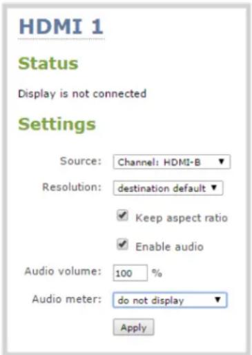
Settings page with a video source (HDMI-A) as the source.
-
From the Source drop down, select the source (prefixed by the word Source) you'd like to view on the video output port.
-
From the Resolution drop down, select the desired resolution to display on the video output port.
| Value Description | |
| Same as source | Set the output to the same resolution as the source. If that resolution is not supported by the display, the videooutput port will negotiate a new resolution with the display (generally this ends up being the display's default resolution). |
| Destination default | This is the default value. Each display has a preferred resolution, and when you choose this setting, the video output port will use the display's default resolution. |
| 640×360, 640×480, 960×540,1024×768, 1280×720, 1280×960,1360×768, 1400×1050, 1920×1080,1920×1200, 2560×1440,3840×2160 ^4K , 4096×2160 ^4K | Choose a specific resolution for the output port. For an explanation of the different choices, seeShow a source on the video output port. |
-
Check the Keep aspect ratio check box to have the system maintain the correct aspect ratio by adding black bars at the top and bottom or left and right sides of the video if the aspect ratio is different between the source and the chosen display aspect ratio. Uncheck to have the system stretch the source to fit the aspect ratio of the display.
-
Configure the Frame rate field to specify the number of frames per second sent out over the video output port.
-
Click Apply.

You can also set your sources to display via the video output ports using the Epiphan Live control interface. See Configuring and monitoring video outputs for more information.
Select a resolution for the video output port
The video output port's resolution (also known as frame size or display mode) is a count of the number of pixels displayed horizontally and vertically. For example, the resolution 1920×1080 (1080p) creates an image that is 1920 pixels wide and 1080 pixels tall.

Pearl-2 always assumes that the output display uses square pixels.
The aspect ratio of an image (eg. 4:3 or 16:9) describes the proportional relationship between its pixel width and height. The resolution 1920 × 1080 (1080p) is quite a bit wider than it is tall. The ratio of its width to height is 16 to 9, represented as an aspect ratio 16:9.
By default you can choose from the following output resolutions for your video output ports, but you can also change settings to allow a variety of other resolutions through.
Aspect ratio legend
| Aspect Ratio Common Use | |
| 4:3 | Standard TV (NTSC/PAL) display and non-widescreen computer displays |
| 16:9 | Widescreen (HD) TV displays (1080p, 1080i, 720p etc), and 4K-capable displays |
| 16:10 (8:5) | Widescreen computer displays, and 4K-capable displays |
| 5:4 | Sometimes used in larger format computer monitors |
| 1.90:1 | Digital Cinema Initiatives standard resolution for 4K or 2K video projection |
Resolutions
| 640×360 640×480 960×540 1024×768 | |
| 1280×720 1280×1024 1600×1200 | 1920×1080 |
| 1920×1200 2560×1440 3840×2160 | 4K 4096×2160 4K |
Preview the video output port
You can preview the video signal that is shared over your video output port by looking at the preview window at the bottom of the video output configuration page in the Admin panel.

The preview is updated every few seconds and always maintains the same aspect ratio as the source it is copying. It doesn't reflect black bars, the audio meter or actual aspect ratio/resolution on the display.

natural_image
Man in business suit and red tie sitting at a desk, reviewing documents (no visible text or symbols)If the video output port is showing a source and that source has no signal, the source's no signal image is displayed.
If the video output port is showing a channel and that channel is unavailable or has no signal, a no signal message is shown for 2.5 seconds, then the display output is changed to a black screen.

You can also preview video output ports using the Epiphan Live control interface. See Configuring and monitoring video outputs for more information.
View the video output port status
At the top of the video output port configuration page is a status section that displays the actual settings used with the attached video display device.
To view the video output status in the Admin panel:
- Login to the Admin panel as admin. See Connect to the Admin panel.
- Click the name of your Output Port (by default called HDMI 1 and HDMI 2); the video output port configuration page opens.
- See the Status section at the top of the page; possible status messages are described in the table below.
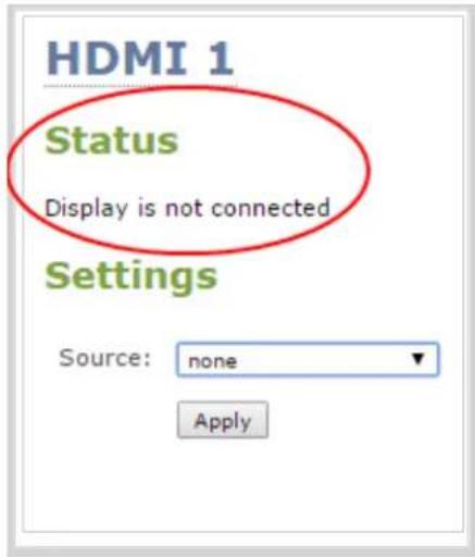
Table 30 Possible video output status messages
| Message Description | |
| Disabled | This video output port is disabled in the configuration. See View the video output port status. |
| Display is not connected | There is no display connected to the video output port or the connected display is not powered on or not functioning. |
| Source is currently unavailable | The video output port is configured to display a channel that no longer exists. Change the source. See View the video output port status. |
| Starting ... | The video output port is configuring the display and will shortly output the first frame. |
| Running at w×h The video output port is functioning at the specified resolution. | |

You can also view video output status using the Epiphan Live control interface. See Configuring and monitoring video outputs for more information.
Disable the video output port
You can choose to disable a video output port, so even if a display is connected, nothing is shown.
To disable the video output port using the Admin panel:
-
Login to the Admin panel as admin. See Connect to the Admin panel.
-
Click the name of your Output Port (by default called HDMI 1 and HDMI 2); the video output port configuration page opens.
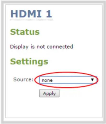
- From the Source select none to disable the video output port.
- Click Apply; the video output port is disabled and status is changed to Disabled.

You can also disable video output ports using the Epiphan Live control interface. See Configuring and monitoring video outputs for more information.
Disable or enable the audio on the video output port
If you're displaying a channel as the source for your video output port, audio for that channel is also encoded and sent over the port. You can choose to disable audio, in which case Pearl-2 will generate silence as the audio output. (Note: audio pass-through functionality is only supported with a channel as the source.)
To disable the audio on the video output port using the Admin panel:
- Login to the Admin panel as admin. See Connect to the Admin panel.
- Click the name of your Output Port (by default called HDMI 1 and HDMI 2); the video output port configuration page opens.
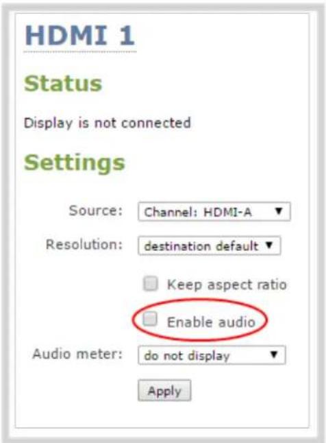
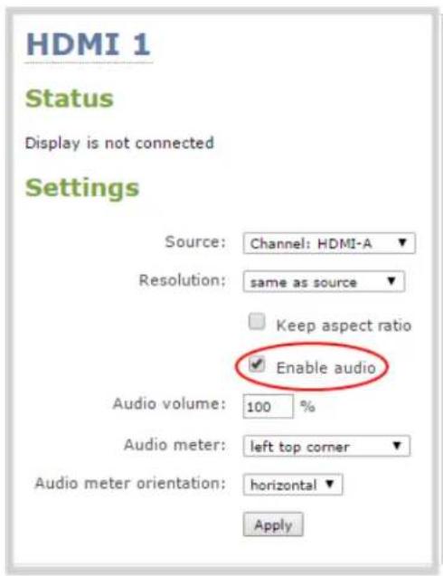
Audio disabled for the video output port Audio enabled for the video output port
- To disable audio, uncheck the Enable audio check box. To enable audio, check it.
- When audio is enabled, a second field appears for Audio volume. Configure with a value between 0 and 100 to moderate the volume of audio output over the video output port.
- Click Apply.

You can also disable or enable video output port audio volume using the Epiphan Live control interface. See Configuring and monitoring video outputs for more information.
Configure the audio meter
When outputting a channel over a video output port, you can choose to output audio and whether or not to include the audio meter. You can control the position and orientation of the audio meter.
To configure the audio meter for the video output port:
- Login to the Admin panel as admin. See Connect to the Admin panel.
-
Click the name of your Output Port (by default called HDMI 1 and HDMI 2); the video output port configuration page opens.
-
Ensure a channel is selected as the source for the video output port. (Audio output and audio meter display are only supported for channels.)
- From the Audio meter drop box select one of the following options.
| Value Description | |
| do not display No audio meter is displayed. | |
| left top corner Audio meter is displayed at the top left side of the display. | |
| right top corner Audio meter is displayed at the top right side of the display. | |
| left bottom corner | Audio meter is displayed at the bottom left side of the display. |
| right bottom corner | Audio meter is displayed at the bottom right side of the display. |
- If you've selected a location for the audio meter, you can also select orientation (horizontal or vertical) from the Audio meter orientation drop down.
- Click Apply.
Rename a video output port
By default Pearl-2's video output ports are named HDMI 1 and HDMI 2. Like channel and source names, you can change a video output port's name to better indicate its use. For example you might want to name one Projector Output and the other Confidence Monitor.
To change a video output port name:
- Login to the Admin panel as admin. See Connect to the Admin panel.
- From the Admin panel, scroll to the Output ports menu option.
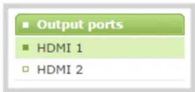
- Click the desired video output port link; the video output port configuration page opens.
- Click the video output port name at the top of the page; the name turns red.
-
Highlight and delete the existing source name.
-
Type a new name.
- Press Enter (on your keyboard) to save the new name.

You must press Enter to save the new name. The Apply button will not save the source name change.
PART 2: Capture
Capturing is the process of taking the signals from your video and audio sources and encoding them in a format that is ready for streaming and recording.
If you followed the quick start guide, you're already capturing, streaming and possibly recording your sources. The section of the guide helps you fine tune and troubleshoot the capturing process.
When using Pearl-2, you can stick to all the default capture and encoding settings, or you tweak them to set the up exactly as you like.
You can capture a single source at once, capture multiple sources in a custom channel or even switch between sources or groups of sources (layouts) while streaming and recording.
Techniques for creating channels to capture, stream and record a single source; to create custom channels with multiple sources and multiple layouts; and how to switch layouts while capturing are all described in this section.
The chapters in this section include:
- Channels
• Live video mixing / switching - Sources
- Troubleshooting
What is a channel?
Pearl-2 uses Channels to organize and display yourHDMI, DVI, SDI, USB video content.
Channels take your video content from the input ports (HDMI, SDI, USB video) and make it available for streaming and recording. You have many creative options available to customize channels. For example, you can apply effects to your sources like a transparent logo or lower third. Easily combine multiple sources in picture in picture layouts and add text overlays. You can even apply chroma key effects to either one or to all your input video sources at the same time.
Pearl-2 gives you a lot of control over how your sources are streamed. You are not limited to creating a Channel list that is a one-to-one reflection of your Sources list. You can make channels from some or all of your sources and you can add the same source to multiple single-source or multi-source layout channels.
For example, you could use the same source in all three of these situations, concurrently:
- as the only source in Channel 1 at 1080p, 30fps, 10,000 kbps;
- as the only source in Channel 2 at 720p, 15 fps, 2,000 kbps;
- in Channel 3 as part of a multi-source layout with picture in picture.
All channels can be streamed and recorded simultaneously. Following the example above, you could record any combination of those three channels, and stream one, two or all three of them using any available streaming methods.
In addition to creating multi-source channels, you can customize your channels by adding images, company information, corporate colors and time stamps. Pearl-2 has a visual layout editor to help you create exactly the layout you want to stream.
For each channel you create, you can use the custom layout editor to create one or more custom layouts. Then you can switch live between different layouts while recording or streaming. To create custom layouts, read Create a custom channel and Custom channel layout editor. To learn how to do live video mixing and live video switching, see Live video mixing / switching.

You can also view channels and perform live switching using the Epiphan Live control interface. See Configuring Dashboard panels for visual confidence monitoring and Switching while live streaming and recording for more information.
You can create and upload customized "No Signal" images for use in your channels. These images are assigned to a specific source and display in any channel where the source is used but has no input detected. For more information on how to create a "No Signal" image, see Add a No Signal image to a source.
Channels
Through channel configuration and fine-tuning you can maximize your stream quality, minimize your processing requirements and bandwidth. You can also specify how the video is presented and streamed to sharing destinations and viewers. Topics in this section include:
• Use the automatic channels Auto A and Auto B
• Create a simple channel
- Configure encoding
• Create a custom channel
- Custom channel examples
- Custom channel layout editor
- Add a video source (custom channel)
- Add an audio source (custom channel)
- Add an image (custom channel)
- Add a text overlay (custom channel)
- Configure chroma keying
• Live video mixing / switching
- Preview a channel
- Duplicate a channel
- Delete a channel
- Rename a channel
Use the automatic channels Auto A and Auto B
To get you started as quickly as possible, Pearl-2 comes pre-configured with two channels: Auto A and Auto B.
To use these channels, simply plug a source into one of the Row A inputs and, if desired, a second source into one of the Row B inputs. The system automatically configures the channel's frame size to match the source resolution and configures a frame rate and bit rate. Audio, if present, is automatically added to the channel.

Default audio setup for the auto channels is always as follows:
| Video Source Audio Source | |
| SDI SDI Audio | |
| HDMI (DVI) HDMI Audio (no audio for DVI) | |
| USB video USB audio |
You can start viewing the channel immediately on the touch screen display (if enabled) or by using an internet browser on the same LAN or network. Browse to the following URL:
For Auto A: http://
Or, if Bonjour services (which permit browsing by serial number) are not installed on the computer you can obtain the IP address from the touch screen display, if enabled, and browse to:
For Auto A: http://
You find alternate connection streams (i.e. RTSP or MPEG-TS) and can further configure these channels by logging into the Admin panel and accessing Auto A and Auto B using the links under the Channels menu.

You can delete the Auto A and Auto B channels, but they will re-appear upon factory reset or when loading the default configuration profile.
Know which signal is used for Auto-A or Auto-B
Pearl-2 has video input sensing, meaning it knows when there is a video signal coming through from an attached source.
If you attach more than one source to a row while Pearl-2 is turned on, the first source to be attached has the highest priority. However, if you attach more than one source to a row prior to powering on Pearl-2, the following priority is used:
| Priority Connector Type | |
| 1 HDMI (with HDMI Audio) | |
| 2 HDMI 4K | 4K (with HDMI Audio) |
| 3 SDI (with SDI Audio) | |
| 4 USB video (with USB audio) | |
The auto channel uses a source until the source has no signal, then switches to the highest priority signal found.
For example, if you attach SDI into the "A" slot, then HDMI into the "A" slot as well, then Auto A will show HDMI and use HDMI audio until such time as the SDI video signal is lost or you use the audio input selection option in the sources section. At that time Auto A will switch to SDI video with XLR audio.
If all the connected sources lose signal at the same time (i.e. for the example above when SDI loses video signal, and no other video signal is found on the HDMI source) no change is made and the auto channel continues to use the current source. In this case, a no signal image is displayed for viewers. See Add a No Signal image to a source for more information on setting no signal images.
Configure auto channels
Auto channels are included with Pearl-2 to make setup quick and simple. However if you want to set custom encoding or streaming configuration for the channel, you can configure it like any other channel.
To further configure automatic channels Auto A and Auto B:
-
Login to the Admin panel as admin. See Connect to the Admin panel.
-
Scroll to the Channels section.
-
Click Auto A or Auto B from the Channels section; the channel's status page opens.

- Configure the channel as you would any other channel. See below.

You can change the source used for the two auto channels by selecting a different source from the layout editor in the Sources page. When you do this, the channel name changes to reflect the new source (if that is the only source is used for the channel). No auto switching is performed. This is desirable if you know, for example, that you will always use SDI video with XLR audio and you never need the automatic switching capabilities of the auto channels.
Create a simple channel
Channels arrange the output from sources into a viewable and recordable stream. Although there are may ways you customize a channel, this procedure walks you through the most basic channel setup with a single source. For multiple-source channels and advanced layout editing see Add channel metadata. (You can always update this channel later to use multiple sources or multiple layouts.)
After creating this channel you'll be ready to stream it using the system default settings. Instructions to configure encoding, branding and CDN streaming are described in separate procedures.
To create a simple channel:
-
Login to the Admin panel as admin. See Connect to the Admin panel.
-
Ensure that your choice of HDMI, DVI, SDI, USB video sources and your audio are connected to the device, and you know the name of the source it is connected to. If you're not sure, see What is a source?
- From the Admin panel, scroll to the Channels menu option. A list of existing channels, if any is displayed.
- Click Add channel located at the bottom of the list; the Sources page opens.

- You're automatically editing the Default layout in the channel layout editor. (By default a 16:9 visual layout editor with a no-signal image is shown.)
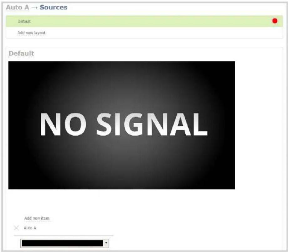
- Click Add new item to add a layer to the layout; a drop down appears allowing you to choose the kind of item to add to your layout.
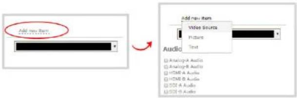
- Select Video Source from the drop down; the new item is added to the layout and the Source settings box appears on the right side of the page.
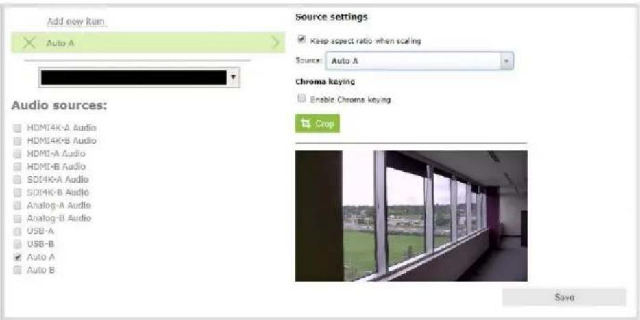
- Click the Source drop down and select your source; your source appears in the visual layout editor above.

-
For best results, keep the Keep aspect ratio when scaling checkbox checked in the Source settings box.
-
Click and drag the red and white source handles in the visual editor or type in the percentage text boxes at the side to re-size the image as you wish. For a single source channel, using the full layout is usually best.
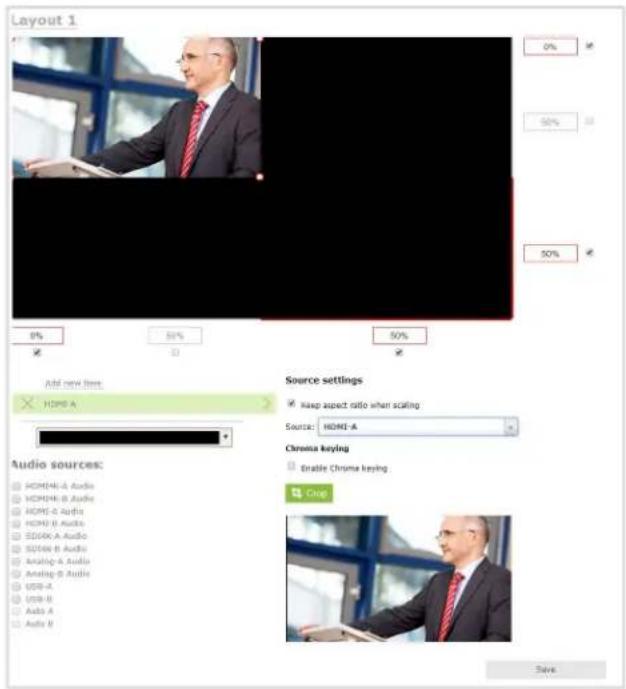
- If audio is desired, scroll down and choose an audio source from the displayed list.

If an Auto channel is selected as a video source, then Auto A or Auto B audio is selected by default.
- Click Save at the lower right corner of the page; the layout changes are saved.

Because this is a single-source channel with only one layout, the channel's name is updated to display the source's name next time you view the channel. Click the channel name to refresh and view this, if desired. If you wish to change a channel's name directly, see Rename a channel.
Your channel is ready for basic streaming and recording.

By default (on a new channel), when the source doesn't have a 16:9 aspect ratio, the system automatically detects the correct aspect ratio and updates the layout after you leave and return to the layout editor screen. This happens because the encoding page has the Use current signal resolution as frame size setting selected by default. If you want to change the aspect ratio for your channel, see Configure encoding.
There are a lot of creative things you can do next with your channel, including creating more layouts and editing this layout to add images and more sources. See Create a custom channel for more information.
Create a custom channel
Pearl-2 has two styles of channels:
- Simple channels with a single source that fits the full screen, as discussed in Create a simple channel.
- Custom channels with one or more layouts, sources, background matte color and images.
You set up simple and custom channels using the same user interface.
Simple and custom channels do essentially the same thing. The main difference is that custom channels have multiple sources, image elements, multiple layouts or any combination of those items added. So the only distinction between simple channels and custom channels is the you've added extra elements to the channel.
A simple channel has one source that fills the whole screen, but with custom channels, you can arrange and resize multiple video sources, add pictures and even add text overlays using custom layouts. Each custom channel you create can have multiple custom layouts.
To do video switching (or video mixing) while you're streaming live, create a custom layout for each view that you want to switch between. You can switch live between the custom layouts using the Admin panel or Pearl-2's touch screen.

If you're planning to do live switching with your channel, we recommend you set the frame size to a fixed size instead of using the default automatic detection of source frame size. Setting the frame size to a fixed value ensures you don't experience any stream interruptions if the source frame size changes due to layouts that contain a single source that has a different frame size than those in other layouts.
As you saw when creating a simple channel, the first thing you need to do is create your (first) layout. Before getting started with custom channel layouts, we recommend you review the Custom channel layout editor and get some inspiration from our Custom channel examples. Then use the remaining topics in this section to help you create and configure your perfect custom channel layouts!
• Create a custom channel or layout
• To upload an image
- Delete an uploaded image
- Add an image (custom channel)
- Add a video source (custom channel)
- Add an audio source (custom channel)
- Custom crop a source
- Configure chroma keying
- Set the background color (custom channel)
- Add a text overlay (custom channel)
- Delete, move, or duplicate a layout (custom channel)
- Resize and position layout items using percents or pixels (custom channel)
- Rename a layout (custom channel)
After your custom layouts are created, read about Live video mixing / switching to learn how to switch layouts while streaming and/or recording.

Each layout you add to your channel adds overhead on Pearl-2- and more complex layouts take more resources. So it's a good idea to delete any layouts you're not using.
Custom channel layout editor
The visual channel layout editor gives you full control on size and position of the pictures, sources and text overlays you add to your channel.
You can edit existing channel layouts (even ones you initially created as simple channels) or you can create a new channel or a new layout within a channel to work with. To add a new layout, see Create a custom channel or layout.
To select a layout for editing:
- Login to the Admin panel as admin. See Connect to the Admin panel.
- Select your channel from the channels menu and click Sources for the channel.
- Select the layout you want to edit by clicking anywhere in the layout row; the layout editor shows the current state of the selected layout for your channel and the row for the layout you're editing is highlighted green.

- If this is a new layout, you are presented with an empty layout area and a black background matte.
The Sources page and channel layout editor is broken into a few pieces.
Layout selector
First there is the layout selector. From here you can pick which layout to preview/edit, create a new layout, delete a layout or select which layout is active.

flowchart
graph TD
    A["Click and drag to reorder"] --> B["Default"]
    B --> C["Add new layout"]
    D["Currently editing this layout (green background)"] --> E["Layout 3"]
    E --> F["Layout 3"]
    F --> G["Click anywhere on a row to edit that layout"]
    H["Currently live layout"] --> I["Active"]
    I --> J["Click to make a different layout live"]
    K["Click to add a new layout"] --> L["Click to duplicate layout"]
Visual channel layout editor
Next is the channel layout editor where you can add pictures, sources and text overlays to your layout. You can also choose the background matte.
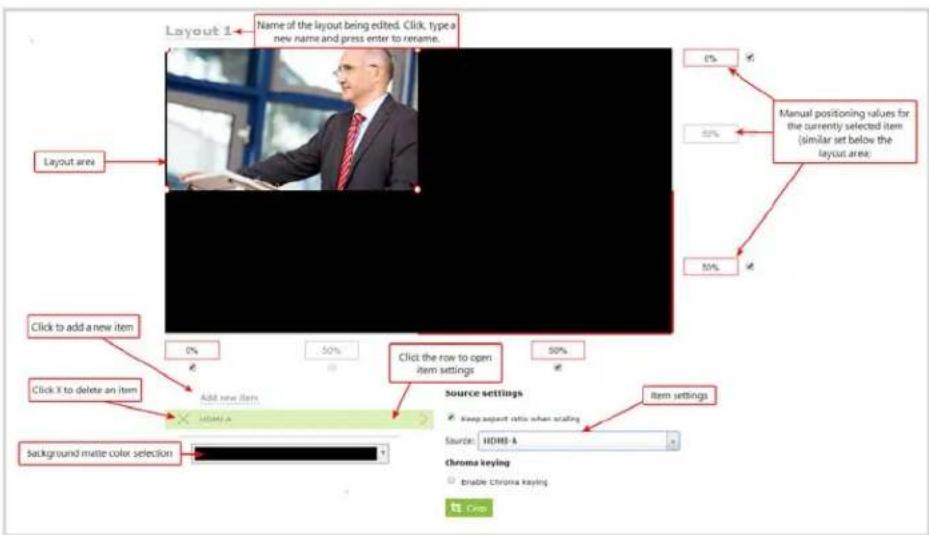
The heart of the channel layout editor is the layout area, which has the same frame size and aspect ratio as your stream. As you add items to the layout, they appear in the layout area. The currently selected item is presented in full color while other items appear transparent.
To position the items you can use the mouse to click and drag, or you can use the manual positioning values to set a location as a percent of the screen (by typing a value followed by the percent sign, e.g. 4%) or in pixels (by typing a value followed by px, e.g. 16px).
You can resize items by clicking and dragging the red and white circles at the corners of the items or by using the manual positioning values. For example, entering 0% in all four of the outside boxes will stretch the item to the full size of the layout area.
You can modify the settings for each item by clicking the row. The item's settings box appears. See Add an image (custom channel), Add a video source (custom channel) and Add a text overlay (custom channel) for more details on item settings.
Audio source selector and save button
The last section of the Sources page is the audio selector and the (very important) Save button.
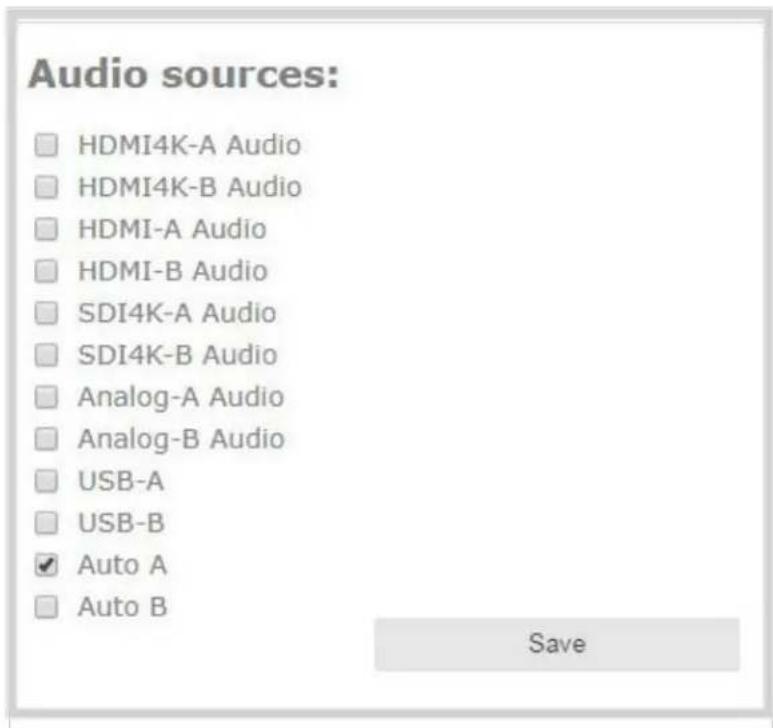
Select the audio source(s) you want to add to your channel.

If an Auto channel is selected as a video source, then Auto A or Auto B audio is selected by default.
Audio sources are mixed together at the same volume level as one another.
When you're done all your changes, use the Save button to save the changes to your layout.
If you leave the layout without saving, Pearl-2 reminds you to save before leaving. Ensure that your bwoser settings allow for the Pearl-2 Admin panel to create pop-up boxes.

Ready to make some layouts of your own? Try these topics:
• Create a custom channel or layout
- Add a video source (custom channel)
- Add an audio source (custom channel)
- Custom crop a source
- Add an image (custom channel)
- Add a text overlay (custom channel)
- Delete, move, or duplicate a layout (custom channel)
- Set the background color (custom channel)
- Rename a layout (custom channel)
Custom channel examples
Here are a few examples of what you can do with just two sources and two picture files. Use your imagination to create the layouts you want!
| Layout example Description | |
| epiphan video Virtual Labs and Tutorials Virtual Labs/Tutorials Provide a complete view of the lab or tutorial Share multiple devices in real time include cameras, laptops, oscilloscopes, microscopes Simple Integration with Web Conferencing Systems Use standard web conferencing software and easily share your lab equipment with the participants Simple sharing via Skype, GoToMeeting, Google Hangouts, YouTube Live, Vidyo, Adobe Connect and many others. C 2023 Epiphan Systems Inc Video Streaming & Recording in Education | One source (a slideshow presentation in this case), at the full size of the channel. (Simple channel) To get this look: Add one source to the layout, select keep aspect ratio and stretch to fit the full layout size. |
| epiphan video Virtual Labs and Tutorials Virtual Labs/Tutorials Provide a complete view of the lab or tutorial Share multiple devices in real time Include cameras, laptops, oscilloscopes, microscopes Simple Integration with Web Conferencing Systems Use standard web conferencing software and easily share your lab equipment with the participants Simple sharing via Skype, GoToMeeting, Google Hangouts, YouTube Live, Vidyo, Adobe Connect and many others. C 2023 Epiphan Systems Inc Video Streaming & Recording in Education | One source (a slideshow presentation in this case), with a green background matte. To get this look: Select a background color. Add a source to the layout and size appropriately, leaving the background matte visible. |
Layout example Description

natural_image
Woman speaking at a podium with a microphone, gesturing with her hand (no visible text or symbols)One source with a logo (.png with transparency) in the bottom left corner.
To get this look: Upload an image with transparency through the Branding Content page. Follow the steps from the first example to add the source, then add a picture item and place it where desired.

One source with a text overlay in the bottom right corner.
To get this look: Follow the steps from the first example to add the source, then add a text overlay item to the layout. Enter your text in the settings box and place it where desired.
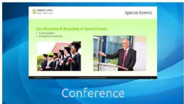
One source with a background image.
To get this look: Upload your background image (must have the right aspect ratio) through the Branding Content page. When creating the layout, first add the picture and stretch it to the full screen. Next, follow the steps from the first example to add the source.
Layout example Description

Two sources with a background image.
To get this look: Follow the steps for the example above, then add and position a second source.
Two sources (one cropped to a new aspect ratioCustom crop a source), a background image and a logo.
To get this look: Upload your background and logo images through the Branding Content page. When creating the layout, first pick the background, then the sources, and lastly the logo. Size and position each. For the second source, use the Crop tool to set the video to a specific aspect ratio or size, and crop until you achieve the desired result.
A few more examples, this time including a 4x3 source.
Layout example Description
One source, at the full size of the channel. (Simple channel)
To get this look: Add one source to the layout, select keep aspect ratio and stretch to fit the full layout size. (Note the channel broadcasts in 4x3 if you have Use current signal resolution as frame size selected on the encoding page.)
| Layout example Description | |
 | One 4x3 source in a 16x9 frame, with a green background matte.To get this look: Make sure your encoding page has a 16x9 frame size. From the sources page, select a background color. Add a source to the layout and stretch to the full height of the screen, leaving the background matte visible. |
 | A 4x3 source and a cropped 16x9 source together with a background image.To get this look: Upload an image through the Branding Content page. Follow the steps from the first 4x3 example (two rows up) to add the sources then use theCroptool to crop the second source to a square aspect ratio. |
Time to get started on your own layouts! See:
• Create a custom channel or layout
- Custom crop a source
- Custom channel layout editor
Create a custom channel or layout
We call a channel a custom channel (or custom layout channel) when is has multiple sources, image elements, multiple layouts, or any combination of those items. Custom layouts give you full control on size and position of the pictures, sources and text overlays you add to your channel.
Use this procedure to help you create a new channel or layout, then use the related procedures to add elements to your layout.

If you're planning to use live switching, we strongly recommend you rename the channel rather than using the default channel name (Rename a channel). See the note at the bottom of this
topic to avoid streaming and recording issues resulting from adding or deleting layouts when live switching.
To create a new custom channel (with default layout) or add a layout to an existing channel:
- Login to the Admin panel as admin. See Connect to the Admin panel.
- Do one of the following to make the Sources page appear:
a. select your channel from the channels menu and click Sources for the channel; or
b. select the Add channel link to create a new channel.
- Next, pick one of the following actions to create or select a layout to edit:
a. select the layout you want to edit by clicking anywhere in the layout row; or
b. click Add Layout to create a new layout.
- The layout editor shows the current state of the selected layout for your channel and the row for the layout you're editing is highlighted green.
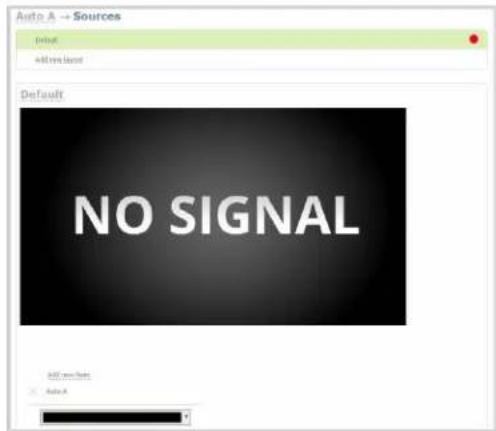
- If this is a new channel or layout, you are presented with an empty layout area with a black background matte.
Now that you've created your layout, you can start adding items to it. See these topics:
- Add a video source (custom channel)
- Add an audio source (custom channel)
- Custom crop a source
- Configure chroma keying
- Add an image (custom channel)
-
Add a text overlay (custom channel)
-
Delete, move, or duplicate a layout (custom channel)
- Set the background color (custom channel)
- Rename a layout (custom channel)
Important note for channels with multiple layouts
By default (and historically), Pearl-2's channels are named automatically based on the content in the channel.
When a channel has only one layout, and that layout has only one source (regardless of whether or not there are pictures or overlays in the layout), the channel name is the same as the source name.
For example: By default, a channel with one layout that has HDMI-A in it will be named HDMI-A.
When you add a second layout to a channel, the channel name changes to a generic name Channel X (where X is the channel index number). Normally this wouldn't pose any problem, but the changing name does have some side effects: the stream is stopped and restarted, and the channel's recorder (if recording) is stopped and a new file is started.
Furthermore, when you delete layouts in a channel until there is only one layout (with one source) left, the channel name reverts to the source name.
To avoid any issue with changing channel names on channels where you'll have more than one layout, we strongly recommend you rename the channel to a custom name (Rename a channel. This will ensure no automatic channel name changes.
Add a video source (custom channel)
A source needs to be added to a channel before the channel is ready to stream. In the case of custom channels with layouts, you can add one or more sources to the layout area.

When adding more than one source to a custom channel, we recommend configuring the channel to use a fixed resolution instead of using the current signal resolution as the frame size (see Configure encoding). A fixed channel resolution ensures that your channel will display properly in all preview modes (touch screen, Epiphan Live and Admin panel).
You can add a source to a layout on an existing channel or you can create a new channel. If you're not sure how to create a channel or a layout, start by reviewing the first few steps in the topic Custom channel layout editor or start with Create a simple channel.
To add a source to your layout:
-
Login to the Admin panel as admin. See Connect to the Admin panel.
-
Follow the steps in Custom channel layout editor or Create a custom channel or layout to get to the channel layout editor.
- From the channel layout editor, click Add item; a drop down box appears. (If you have any other items already in your layout, the new item appears at the top of the list.)
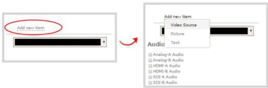
- Select Video Source from the drop down; the new item is added to the layout and the Source settings box appears on the right side of the page.

- Click the Source drop down and select your source; your source appears in the visual layout editor above.
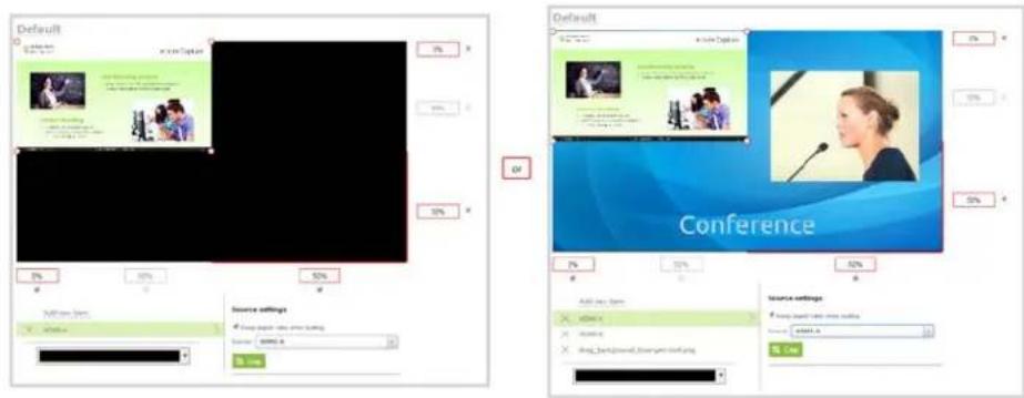
-
For best results, select the Keep aspect ratio when scaling checkbox from the Source settings box.
-
If desired, select Crop from the Source settings box, and follow the instructions to Custom crop a source; your cropped selection changes in the layout area.
-
Moving back to the layout area, use the mouse, the keyboard or the manual position value fields to position and resize your source. You can click and drag, stretch using the handles in the layout area, or type values into the fields. See the note below for more information.

- If needed, re-order the items in your layout by clicking and dragging items in the item list (under the Add new item link).
For example, if you added your video source over a text overlay, the video source could conceal the overlay. To fix it, drag the video source item below the text item in the list, or vice-versa.
- When your layout is complete, scroll to the bottom of the page and click Save to save your work.
Other things you may want to add to your layout:
- Add an audio source (custom channel)
- Custom crop a source
- Add an image (custom channel)
- Add a text overlay (custom channel)
- Delete, move, or duplicate a layout (custom channel)
- Set the background color (custom channel)
- Rename a layout (custom channel)
A note about item positioning and sizing
There are four ways to position and size items in the layout area
- using the mouse
- using the keyboard
- using the manual positioning values with percents
- using the manual positioning values with pixels
To use the mouse:
Click and drag to move the item. Click and drag the round, red and white handles to resize an image or video source (for text overlays, just use the padding settings). Using this method you can make quick changes that are in increments of approximately 5% of the width or height of your layout area. For more refined movements, press the Ctrl key on your keyboard while dragging the item with the mouse.
To use the keyboard:
Use the arrow keys on the keyboard to move the item up, down, left or right in the layout. Changes are in increments of approximately 5% of the height or width of the layout area. Press the Ctrl key while using the arrow keys to make more refined movements. To change the size of an image or video source, press the Shift key while using the arrow keys (for text overlays, just use the padding settings). Press both Ctrl and Shift for fine-grained size control.
Using percents:
Specify a whole number, followed by a percent sign (e.g. 4%) in any of the manual positioning fields. See Resize and position layout items using percents or pixels (custom channel) for more information.
Using pixels:
If you need to specify an exact amount in pixels (rather than percent) you can type a pixel value in any of the positioning value squares followed by the characters px (e.g. 56px). You can mix and match pixels and percents changing only the boxes you want to use pixel values. At any time you can switch
back to percents by typing a percent. See Resize and position layout items using percents or pixels (custom channel) for more information.
Add an audio source (custom channel)
To stream the audio for a source you need to add it to a channel and make sure audio is enabled in the channel's encoding page. (Audio is enabled in the encoding page by default.)

There is no need to manually add RTSP audio sources to your channel. When an RTSP stream is connected to your Pearl-2 as an input source, a corresponding audio source is automatically added to the list of audio sources for your channels, even if there is no audio in the RTSP stream.
Audio must be added to each layout for your channel. You can use the same audio for each layout, or if you desire, you can have different layouts use different audio. If you're not sure how to create a channel or a layout, start by reviewing the first few steps in the topic Custom channel layout editor or start with Create a simple channel.
To add an audio source to your layout:
- Login to the Admin panel as admin. See Connect to the Admin panel.
- Follow the steps in Custom channel layout editor or Create a custom channel or layout to get to the channel layout editor.
- Select the audio source(s) you want to add to your channel. Audio sources are mixed together at the same volume level as one another.
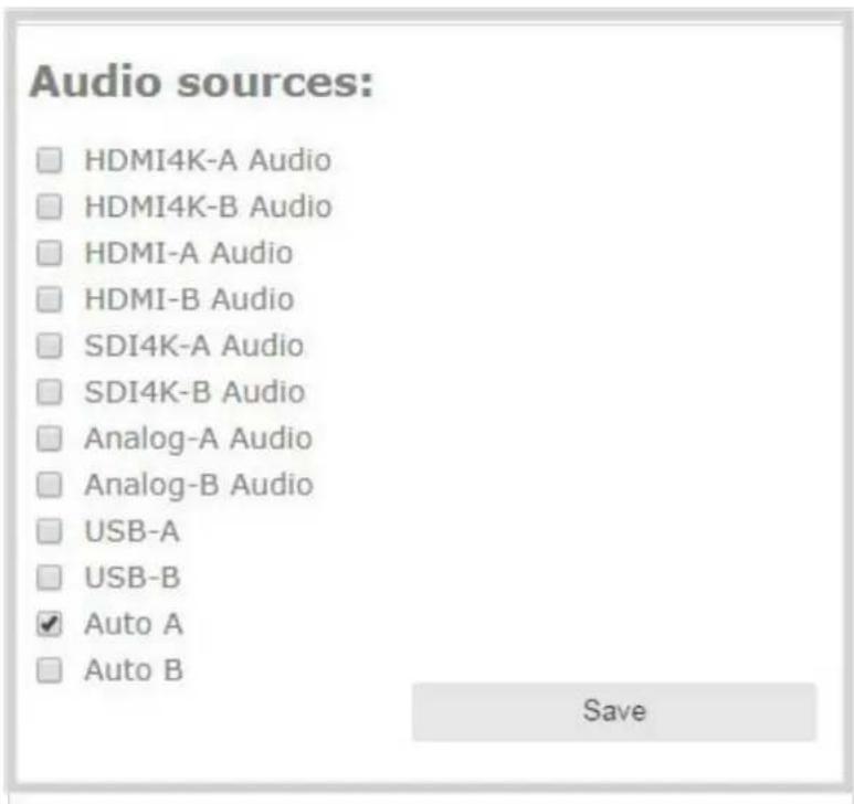
- When your layout changes are complete, scroll to the bottom of the page and click Save to save your work.
- Follow the steps in Configure audio codec to ensure audio is enabled for your channel and to select your audio settings.

The right-most XLR audio input and the RCA audio input are linked within Pearl-2. This means that if you use both simultaneously, their audio will become mixed, and their input is mixed with unpredictable gain levels for each. To avoid this, when you are using RCA, you can only use the left-most XLR audio pair and the SDI and HDMI audio inputs.
For analog audio signals, you may want to check audio levels on your channel and adjust audio gain, if needed. See Adjust audio gain (analog audio) and delay.
Other things you may want to add to your layout:
- Add a video source (custom channel)
- Custom crop a source
- Add an image (custom channel)
- Add a text overlay (custom channel)
-
Delete, move, or duplicate a layout (custom channel)
-
Set the background color (custom channel)
- Rename a layout (custom channel)
Custom crop a source
You can change the size and shape of your video using the crop tool on the Sources page. Cropping a source gives you a lot of advantages. You can capture a 1080p section from a 4K source, a specific aspect ratio or size from a source, or select a crop that fits into your layout better than the full area of your video.
To crop a source in your layout:
- Login to the Admin panel as admin. See Connect to the Admin panel.
- Follow the steps in Custom channel layout editor or Create a custom channel or layout to get to the channel layout editor.
- From the channel layout editor, click Add new item; a drop down box appears. (If you have any other items already in your layout, the new item appears at the top of the list.)

- Select Video Source from the drop down; the new item is added to the layout and the Source settings box appears on the right side of the page.
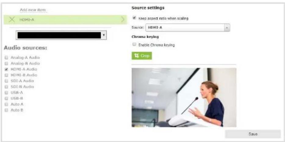
- Click the Crop button; your source appears in a pop-up crop editing window.

- The Crop window has several tools for creating the best crop possible.
- Free form mode is the default crop mode, which you can selected at any time. In this mode, you can change the size, aspect ratio, and position of the crop with minimal restrictions.
- The red box with circular click-and-drag points indicates what your crop shows in the final layout. The channel only shows the part of the source within the box. In Free form mode, you can click and drag the red circles to change the size and ratio of the box, and you can click and drag the box itself to change its position. When you have selected an aspect ratio, you can alter the size by dragging the red circles. When you have selected a size, you can change its position by dragging the box.
- The number boxes allow you to make precise crops. Click the text boxes and change the number to determine how many pixels distant from the edge that line is drawn. If you wish, you may also erase the "px" after the number and type in "%" to manipulate the box using percentages. For more details on how these boxes work, look at Resize and position layout items using percents or pixels (custom channel).
- To create a crop with a specific resolution, choose a Size from the available list. This creates a box with that exact resolution. Click and drag this box to move it to the desired position. Its size cannot be altered except by selecting a different size, or by selecting Free form or Aspect Ratio.
- Selecting an aspect ratio allows you to create a crop box of almost any size in a particular ratio. After selecting a ratio, you can manipulate the crop area's size and position without changing its shape.
- At any time, click Cancel, and all changes made to the crop are undone and you are returned to the layout customization screen.
-
At any time, click OK, and all changes made to the crop are confirmed and you are returned to the layout customization screen.
-
When you have used the tools as outlined above to achieve the desired crop and clicked OK to finalize the changes and return to the main layout page, you can use the tools outlined in Add a video source (custom channel) to further customize the cropped source. You can change the style of your crop at any time by returning to the Crop tool.

You can also manipulate the crop-box using keyboard controls. You can move the crop box using the arrow keys, and holding Ctrl or Shift while resizing the box keeps the aspect ratio of the box constant. Hold Shift and use the arrow keys to move one side of the box while leaving the other in the same location.
Configure chroma keying
Pearl-2 supports chroma keying so you can add special effects to any video source in a custom channel. Add great looking effects such as animated lower thirds using a titler software or add a custom background using green screen. It's easy to get creative.
With chroma keying, you can choose a specific color in your video scene and replace everything of that color with a different image or video.
The most common color used for chroma keying is green. In this example, the original video source shows someone standing in front of a green screen. Using chroma key in Pearl-2, an image of an office space replaces the green background.
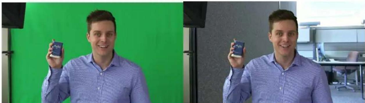
natural_image
Two men in a studio setting, one holding a small product, against a green and gray backdrop (no visible text or symbols)
White, grey, and black are not recommended colors for chroma keying. Those are treated as the same color with a different luminance value. The result in Pearl-2 is that the chroma keying affect gets applied to all shades ranging from white to black.
Performance considerations
Chroma keying can impact the performance of Pearl-2 depending on factors such as how many chroma key sources you add, if you scale the chroma key video source using the custom layout editor, and your frame rate.
For best performance, avoid excessive scaling of video sources that have chroma keying enabled. Cropping video sources that have chroma keying enabled helps reduce processing and optimizes the performance of Pearl-2.
You can monitor the performance of Pearl-2 from the Info tab using the Admin panel for the custom channel that has chroma keying enabled. For more information about performance monitoring, see Using Pearl-2 effectively.
Observe the following:
- For Pearl-2, the maximum resolution is 1920×1080 at 30 fps for chroma keying.
- Avoid scaling a video source that has chroma key enabled.
- Where possible, crop the video source that has the chroma key enabled to minimize the area that Pearl-2 must process for the chroma key effect.
• Overloading the Pearl-2 processor can cause frame drops.
What is upstream chroma keying?
Upstream chroma keying applies the chroma key effect to a specific video source before it's processed, switched, and broadcast.
For example, you could display the name of a guest using titler software on only the camera that is dedicated for close ups of that person but not on any of your other video sources.

To get an upstream key effect using Pearl-2, you can create custom layouts for each video source using the custom layout editor. Then set up chroma keying on just one custom layout. Only the video source that appears in the custom layout with chroma key enabled has the chroma key effect applied to it.
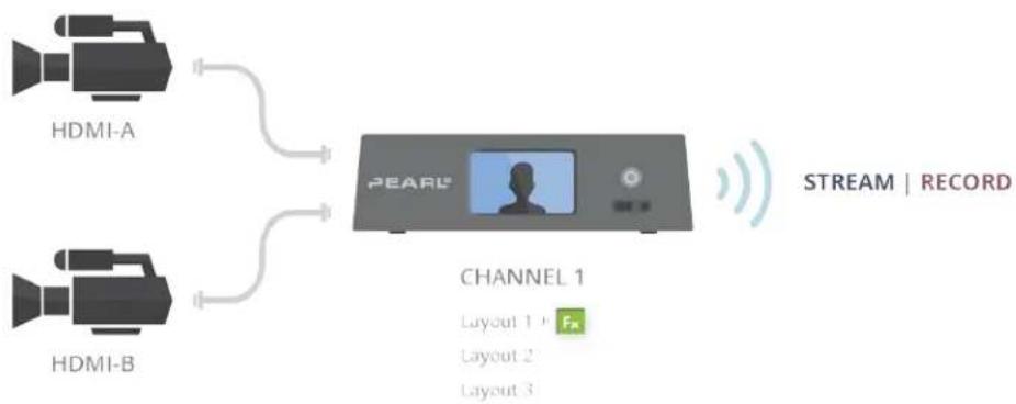
flowchart
graph TD
    A["HDMI-A"] --> C["PEARL"]
    B["HDMI-B"] --> C
    C --> D["CHANNEL 1"]
    D --> E["Layout 1 Fk"]
    D --> F["Layout 2"]
    D --> G["Layout 3"]
    H["STREAM | RECORD"] --> C

If you want to apply the chroma key effect to a video source that appears in several different custom layouts, you must enable the chroma key effect in each custom layout where that particular video source appears.
What is downstream chroma keying?
Downstream chroma keying applies the chroma key effect to all video sources you broadcast after they're processed and switched.
A common use of downstream keying is to display a persistent image, like a company logo, so that it always appears on screen.
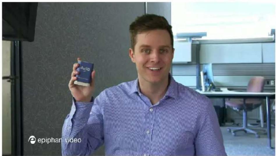
To get a downstream key effect using Pearl-2, you can enable the same chroma key effect on all your custom layouts. This way, the same chroma key effect gets applied to everything you stream or record.
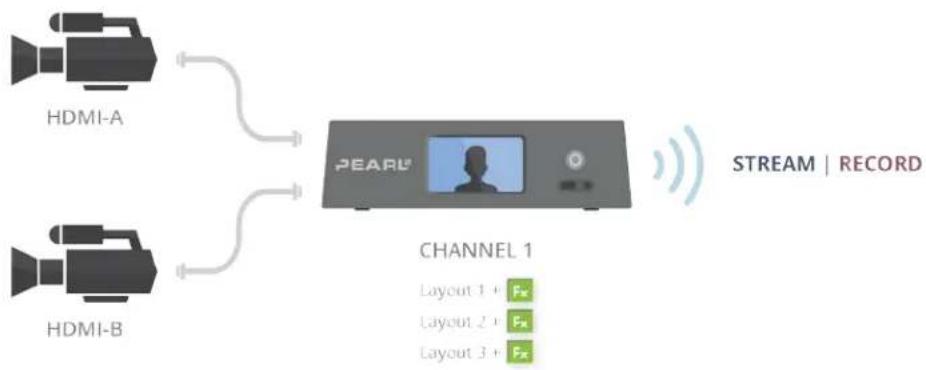
flowchart
graph TD
    A["HDMI-A"] --> C["PEARL"]
    B["HDMI-B"] --> C
    C --> D["CHANNEL 1"]
    D --> E["Layout 1 + Fx"]
    D --> F["Layout 2 + Fx"]
    D --> G["Layout 3 + Fx"]
    style C fill:#999,stroke:#333
    style D fill:#fff,stroke:#333
The following topics appear in this section:
- Set up chroma key for a green screen video source
- Add external title software effects to Pearl-2
- Add chroma key titler effects using Microsoft Powerpoint slides
Set up chroma key for a green screen video source
A common use of chroma keying is to use a green screen and then replace the green background with another video or still image.

natural_image
Two men in a studio setting, one holding a small object against a green screen, the other holding a small object (no visible text or symbols)Your chroma key source can come from a video camera or an effects computer connected to Pearl-2. The background you use can be from another video source, a still image that you've uploaded to Pearl-2, or from an effects computer.
This example shows two camera sources connected to Pearl-2. The green screen appears in the video source connected to HDMI-A and the office background is from HDMI-B.
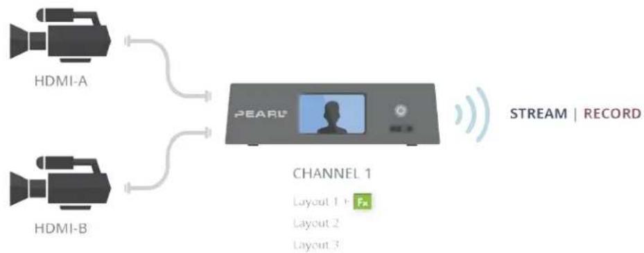
flowchart
graph TD
    A["HDMI-A"] --> C["PEARL"]
    B["HDMI-B"] --> C
    C --> D["CHANNEL 1"]
    D --> E["Layout 1 + Fm"]
    D --> F["Layout 2"]
    D --> G["Layout 3"]
    style C fill:#999,stroke:#333
    style D fill:#cc00,stroke:#333
To configure chroma keying for a green screen video source:
- Login to the Admin panel as admin. See Connect to the Admin panel.
- Follow the steps in Create a custom channel or layout to create a custom channel.
- From the custom layout editor, click Add item; a drop down box appears.

-
Click Source and select the video source that you want showing through the background of your chroma key colored areas. For detailed steps, see Add a video source (custom channel).
-
In the layout area, click and drag to position the video. See the note after this procedure for positioning techniques.

For best results, select the Keep aspect ratio when scaling checkbox from the Source settings box.
-
Click Add new Item again and add the video source that has the green screen image.
-
Click the Crop button and crop your green screen video source in the pop-up crop editing window. For detailed steps, see Custom crop a source. Click OK when your done to return to the custom layout editor.


Cropping the green screen video source helps optimize the performance of Pearl-2.
- In the layout area, position the green screen video source over top the other video source. To optimize performance, avoid scaling the green screen video source if you can.

- With the green screen video source selected, check Enable Chroma keying in the custom layout editor; the chroma keying options appear.


White, grey, and black are not recommended colors for chroma keying. Pearl-2 treats them as the same color with different luminance values. As such, chroma keying affects all shades ranging from white to black.
- Click the eye dropper and then click on a color in the thumbnail image to choose the chroma key color.

The background video image shows through all the colored areas on the chroma key video layer that match the color you select as the chroma key.
- Adjust the chroma color selection and blend the edges to remove unwanted chroma effects or residual color.
a. Enter a number in the Key threshold field to adjust the color selection. A value of 0 equals the original color you selected. A higher value widens the range of the selected chroma color. A lower number narrows the range of the selected chroma color.
b. Enter a number in the Edge blend field to smooth out and adjust the color around the edges in your image.
- When your layout is complete, scroll to the bottom of the page and click Save to save your work.
A note about item positioning and sizing
There are four ways to position and size items in the layout area
- using the mouse
- using the keyboard
- using the manual positioning values with percents
- using the manual positioning values with pixels
To use the mouse:
Click and drag to move the item. Click and drag the round, red and white handles to resize an image or video source (for text overlays, just use the padding settings). Using this method you can make quick changes that are in increments of approximately 5% of the width or height of your layout area. For more refined movements, press the Ctrl key on your keyboard while dragging the item with the mouse.
To use the keyboard:
Use the arrow keys on the keyboard to move the item up, down, left or right in the layout. Changes are in increments of approximately 5% of the height or width of the layout area. Press the Ctrl key while using the arrow keys to make more refined movements. To change the size of an image or video source, press the Shift key while using the arrow keys (for text overlays, just use the padding settings). Press both Ctrl and Shift for fine-grained size control.
Using percents:
Specify a whole number, followed by a percent sign (e.g. 4%) in any of the manual positioning fields. See Resize and position layout items using percents or pixels (custom channel) for more information.
Using pixels:
If you need to specify an exact amount in pixels (rather than percent) you can type a pixel value in any of the positioning value squares followed by the characters px (e.g. 56px). You can mix and match pixels and percents changing only the boxes you want to use pixel values. At any time you can switch back to percents by typing a percent. See Resize and position layout items using percents or pixels (custom channel) for more information.
Add chroma key titler effects using Microsoft Powerpoint slides
You can use the chroma key feature on Pearl-2 with Microsoft Powerpoint slides to add animated titles and other Powerpoint effects. The setup is really the same as using a dedicated titling software on an effects
computer with Pearl-2.

This example shows an HDMI camera connected to the HDMI-A port on Pearl-2 and an effects computer that has a Powerpoint presentation loaded on it connected to the HDMI-B port. To the computer, Pearl-2 is treated just like an external display.
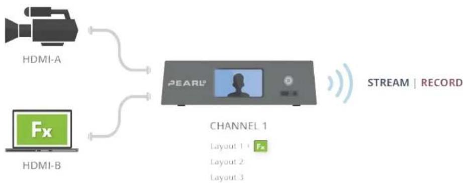
flowchart
graph LR
    A["HDMI-A"] --> C["PEARL"]
    B["HDMI-B"] --> C
    C --> D["CHANNEL 1"]
    D --> E["STREAM | RECORD"]
    D --> F["CHANNEL 1"]
    style A fill:#f9f,stroke:#333
    style B fill:#ccf,stroke:#333
    style C fill:#cff,stroke:#333
    style D fill:#ffc,stroke:#333
    style E fill:#cfc,stroke:#333
    style F fill:#fcc,stroke:#333

You can connect the effects computer with the Powerpoint file to any supported port that is available on Pearl-2.
To apply the chroma key effect to a single video source using Pearl-2:
- Login to the Admin panel as admin. See Connect to the Admin panel.
- Follow the steps in Create a custom channel or layout to create a custom channel.
- From the custom layout editor, click Add new item and select Video Source from the drop down box.
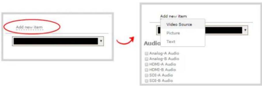
- Click Source and select the video source that you want showing in the background. For detailed steps, see Add a video source (custom channel).
- In the layout area, click and drag to position the video. See the note after this procedure for positioning techniques.

For best results, select the Keep aspect ratio when scaling checkbox from the Source settings box.
- Click Add new Item again and add the video source from your effects computer.
- Click the Crop button and crop your Powerpoint video source in the pop-up crop editing window. For detailed steps, see Custom crop a source. Click OK when your done to return to the custom layout editor.

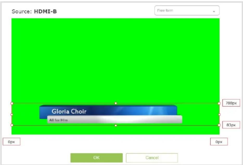

Cropping the Powerpoint computer video source helps optimize the performance of Pearl-2.
- In the layout area, position the Powerpoint video source over top the other video source. To optimize performance, avoid scaling the Powerpoint video source if you can.
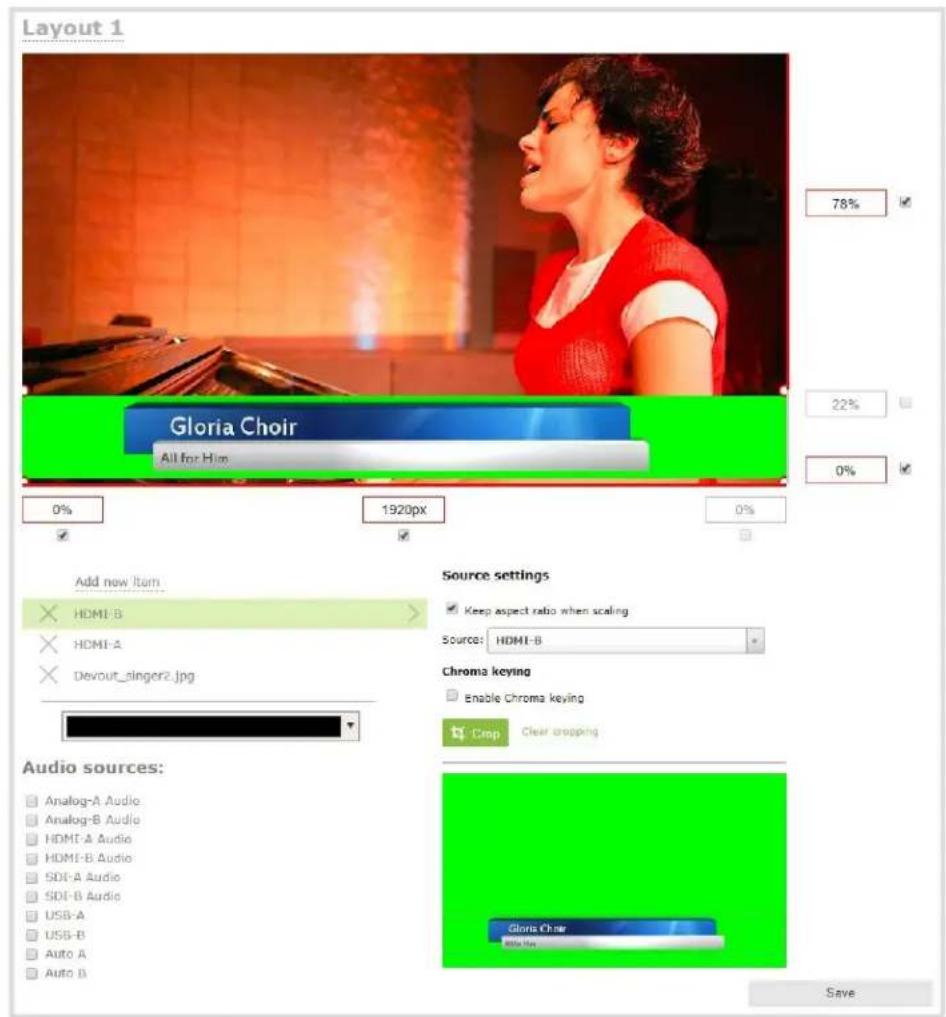
- With the Powerpoint video source selected, check Enable Chroma keying in the custom layout editor; the chroma keying options appear.
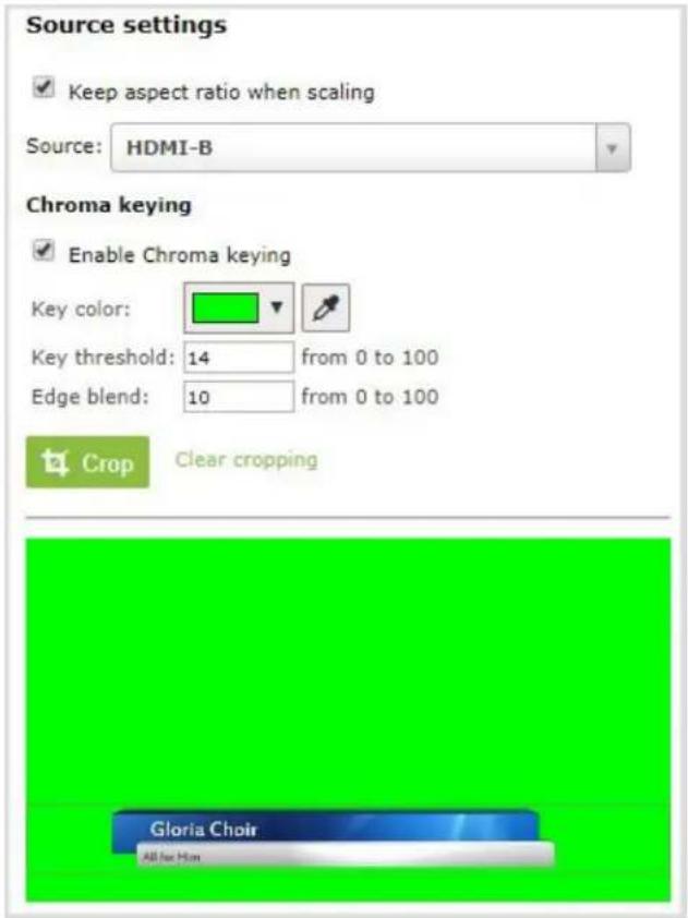
- Click the eye dropper and then click on a color in the thumbnail image to choose the chroma key color.

The background video image shows through all the colored areas on the chroma key video layer that match the color you select as the chroma key.
- Adjust the chroma color selection and blend the edges to remove unwanted chroma effects or residual color.
a. Enter a number in the Key threshold field to adjust the color selection. A value of 0 equals the original color you selected. A higher value widens the range of the selected chroma color. A lower number narrows the range of the selected chroma color.
b. Enter a number in the Edge blend field to smooth out and adjust the color around the edges in your image.
- When your layout is complete, scroll to the bottom of the page and click Save to save your work.
A note about item positioning and sizing
There are four ways to position and size items in the layout area
- using the mouse
- using the keyboard
- using the manual positioning values with percents
- using the manual positioning values with pixels
To use the mouse:
Click and drag to move the item. Click and drag the round, red and white handles to resize an image or video source (for text overlays, just use the padding settings). Using this method you can make quick changes that are in increments of approximately 5% of the width or height of your layout area. For more refined movements, press the Ctrl key on your keyboard while dragging the item with the mouse.
To use the keyboard:
Use the arrow keys on the keyboard to move the item up, down, left or right in the layout. Changes are in increments of approximately 5% of the height or width of the layout area. Press the Ctrl key while using the arrow keys to make more refined movements. To change the size of an image or video source, press the Shift key while using the arrow keys (for text overlays, just use the padding settings). Press both Ctrl and Shift for fine-grained size control.
Using percents:
Specify a whole number, followed by a percent sign (e.g. 4%) in any of the manual positioning fields. See Resize and position layout items using percents or pixels (custom channel) for more information.
Using pixels:
If you need to specify an exact amount in pixels (rather than percent) you can type a pixel value in any of the positioning value squares followed by the characters px (e.g. 56px). You can mix and match pixels and percents changing only the boxes you want to use pixel values. At any time you can switch back to percents by typing a percent. See Resize and position layout items using percents or pixels (custom channel) for more information.
Add external titler software effects to Pearl-2
You can use Pearl-2 with titling software that provides chroma key output to add effects like animated lower thirds.

This example shows an HDMI camera connected to the HDMI-A port on Pearl-2 and an effects computer with title software connected to the HDMI-B port. To the computer, Pearl-2 is treated just like an external display.
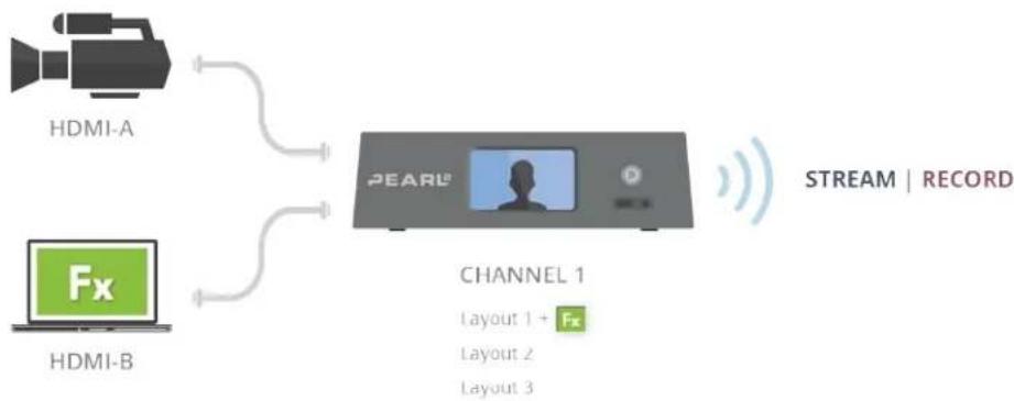
flowchart
graph TD
    A["HDMI-A"] --> C["PEARL"]
    B["HDMI-B"] --> C
    C --> D["CHANNEL 1"]
    D --> E["STREAM | RECORD"]
    D --> F["CHANNEL 1 + FX Layout 2 Layout 3"]

You can connect the effects computer with the titling software to any supported port that is available on Pearl-2.
To apply the chroma key effect to a single video source using Pearl-2:
- Login to the Admin panel as admin. See Connect to the Admin panel.
- Follow the steps in Create a custom channel or layout to create a custom channel.
- From the custom layout editor, click Add new item and select Video Source from the drop down box.

- Click Source and select the video source that you want showing in the background. For detailed steps, see Add a video source (custom channel).
- In the layout area, click and drag to position the video. See the note after this procedure for positioning techniques.

For best results, select the Keep aspect ratio when scaling checkbox from the Source settings box.
- Click Add new Item again and add the video source from your effects computer.
- Click the Crop button and crop your effects video source in the pop-up crop editing window. For detailed steps, see Custom crop a source. Click OK when your done to return to the custom layout editor.
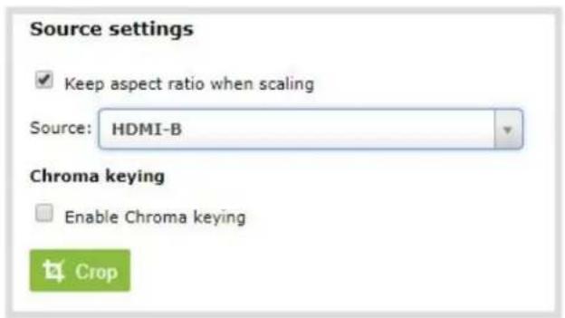


Cropping the effects computer video source helps optimize the performance of Pearl-2.
- In the layout area, position the effects video source over top the other video source. To optimize performance, avoid scaling the effects video source if you can.
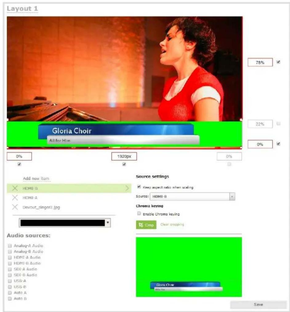
-
With the effects video source selected, check Enable Chroma keying in the custom layout editor; the chroma keying options appear.
-
Click the eye dropper and then click on a color in the thumbnail image to choose the chroma key color.
The background video image shows through all the colored areas on the chroma key video layer that match the color you select as the chroma key.
- Adjust the chroma color selection and blend the edges to remove unwanted chroma effects or residual color.
a. Enter a number in the Key threshold field to adjust the color selection. A value of 0 equals the original color you selected. A higher value widens the range of the selected chroma color. A lower number narrows the range of the selected chroma color.
b. Enter a number in the Edge blend field to smooth out and adjust the color around the edges in your image.
- When your layout is complete, scroll to the bottom of the page and click Save to save your work.
A note about item positioning and sizing
There are four ways to position and size items in the layout area
- using the mouse
- using the keyboard
- using the manual positioning values with percents
- using the manual positioning values with pixels
To use the mouse:
Click and drag to move the item. Click and drag the round, red and white handles to resize an image or video source (for text overlays, just use the padding settings). Using this method you can make quick changes that are in increments of approximately 5% of the width or height of your layout area. For more refined movements, press the Ctrl key on your keyboard while dragging the item with the mouse.
To use the keyboard:
Use the arrow keys on the keyboard to move the item up, down, left or right in the layout. Changes are in increments of approximately 5% of the height or width of the layout area. Press the Ctrl key while using the arrow keys to make more refined movements. To change the size of an image or video source, press the Shift key while using the arrow keys (for text overlays, just use the padding settings). Press both Ctrl and Shift for fine-grained size control.
Using percents:
Specify a whole number, followed by a percent sign (e.g. 4%) in any of the manual positioning fields. See Resize and position layout items using percents or pixels (custom channel) for more information.
Using pixels:
If you need to specify an exact amount in pixels (rather than percent) you can type a pixel value in any of the positioning value squares followed by the characters px (e.g. 56px). You can mix and match pixels and percents changing only the boxes you want to use pixel values. At any time you can switch back to percents by typing a percent. See Resize and position layout items using percents or pixels (custom channel) for more information.
To upload an image
You can customize your channels by adding pictures as backgrounds, overlays or information. Collectively the images you upload to the system are known as branding images.


For best results always upload images that are already the correct size needed in your layout. Background images should match the frame size of your channel (frame size is set in the Encoding configuration page).
There are two ways to upload branding images. You can upload images to the branding page, as described in this procedure, or you can drag and drop images using the procedure described in Add an image (custom channel). Note that using the procedure below is the only way to see whether or not you'll be overwriting an existing image.
To upload a branding image to the branding page:
- Login to the Admin panel as admin. See Connect to the Admin panel.
- Click Branding Content under the Configuration menu; the configuration page opens.
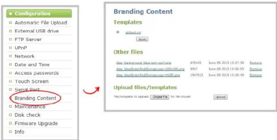
- Click Choose File; a browser page opens.
- Navigate to the folder on your admin computer that contains the logo.
- Select the file, the following file formats are supported: PNG and JPEG.

The maximum supported image size is 3840×2160. No warning or error message is displayed if your image is too large. Files that exceed the maximum size do not appear in the drop-down list when selecting an image.
- Click Open; the file is added to the File/template to upload field.

- Click Upload; the file is uploaded and displayed in the Other files section.

See the following topics to learn how to apply the logo, background, overlay text or other images to a channel:
- Add an image (custom channel)
- Add a text overlay (custom channel)
Add an image (custom channel)
You can use images in your custom channel layouts to create a background for your source, to add your corporate logo, or to add relevant information about the event you're streaming.
Pearl-2 supports png (PNG) and .jpg (JPEG) images. You can upload images that are 16×16 pixels to a maximum image size of 4096×4096; however it's strongly recommended that you upload exactly the size you need to avoid image scaling.
In earlier releases, there were separate procedures for adding backgrounds and logos to a channel. These actions are now both considered adding an image to a custom channel layout and can be accomplished with the steps below.
You can add a picture to a layout on an existing channel or you can create a new channel. If you're not sure how to create a channel or a layout, start by reviewing the first few steps in the topic Custom channel layout editor or start with Create a simple channel.
To add a picture to your layout:
- Login to the Admin panel as admin. See Connect to the Admin panel.
- Follow the steps in To upload an image or Create a custom channel or layout to upload your image, if not already uploaded. If you like, you can also use the drag and drop technique described below.
-
Follow the steps in Custom channel layout editor to get to the channel layout editor.
-
From the channel layout editor, click Add item; a drop down box appears. (If you have any other items already in your layout, the new item appears at the top of the list.)

- Select Picture; the Picture Settings section appears on the right side of the page.

- If you haven't already uploaded your image, you can drag and drop it from your desktop to the gray Please select picture box. (Note: no warning is displayed if the image is too large or will replace another file).
- If you have already uploaded the image, click the Use image drop down to select an image you have uploaded to the system;
- Your picture appears in the Picture settings preview and is added to the layout area. It is selected for sizing and positioning.

If your uploaded image does not appear in the list, ensure it doesn't exceed the maximum image size of 4096×4096.

-
For best results, keep the Keep aspect ratio when scaling checkbox selected in the Picture settings box. (This is selected by default.)
-
In the layout area, use the mouse, the keyboard or the manual position value fields to position and resize your image. For background images, click and drag to fill the full layout area. See the note below for more information on positioning techniques.

- If needed, re-order the items in your layout by clicking and dragging items in the item list (under the Add new item link).
For example, if you added your background image after adding a video source, the background image conceals the video source. To fix it, drag the video source item above the background image item in the list, or vice-versa.
- When your layout is complete, scroll to the bottom of the page and click Save to save your work.
Other things you may want to add to your layout:
- Add a video source (custom channel)
- Custom crop a source
- Add an audio source (custom channel)
- Add a text overlay (custom channel)
- Delete, move, or duplicate a layout (custom channel)
- Set the background color (custom channel)
- Rename a layout (custom channel)
A note about item positioning and sizing
There are four ways to position and size items in the layout area
- using the mouse
-
using the keyboard
-
using the manual positioning values with percents
- using the manual positioning values with pixels
To use the mouse:
Click and drag to move the item. Click and drag the round, red and white handles to resize an image or video source (for text overlays, just use the padding settings). Using this method you can make quick changes that are in increments of approximately 5% of the width or height of your layout area. For more refined movements, press the Ctrl key on your keyboard while dragging the item with the mouse.
To use the keyboard:
Use the arrow keys on the keyboard to move the item up, down, left or right in the layout. Changes are in increments of approximately 5% of the height or width of the layout area. Press the Ctrl key while using the arrow keys to make more refined movements. To change the size of an image or video source, press the Shift key while using the arrow keys (for text overlays, just use the padding settings). Press both Ctrl and Shift for fine-grained size control.
Using percents:
Specify a whole number, followed by a percent sign (e.g. 4%) in any of the manual positioning fields. See Resize and position layout items using percents or pixels (custom channel) for more information.
Using pixels:
If you need to specify an exact amount in pixels (rather than percent) you can type a pixel value in any of the positioning value squares followed by the characters px (e.g. 56px). You can mix and match pixels and percents changing only the boxes you want to use pixel values. At any time you can switch back to percents by typing a percent. See Resize and position layout items using percents or pixels (custom channel) for more information.
Add a text overlay (custom channel)
Adding a static or dynamic text overlay to your custom channel is an easy way to customize your stream.
This topic covers:
- Custom overlay text (static)
- Custom overlay text (dynamic)
You can add an overlay to a layout on an existing channel or you can create a new channel. If you're not sure how to create a channel or a layout, start by reviewing the first few steps in the topic Custom channel layout editor or start with Create a simple channel.
Custom overlay text (static)
In a custom layout, you can manually input your overlay text, such as date and time, channel name or other personalized text. This text remains static and requires manually editing within the custom layout to change.
To add custom overlay text to your layout:
- Login to the Admin panel as admin. See Connect to the Admin panel.
- Follow the steps in Custom channel layout editor or Create a custom channel or layout to get to the channel layout editor.
- From the channel layout editor, click Add item; a drop down box appears. (If you have any other items already in your layout, the new item appears at the top of the list.)

- Use the item type drop down box to select Text; the Text settings box appears and the layout area is updated with the text overlay.
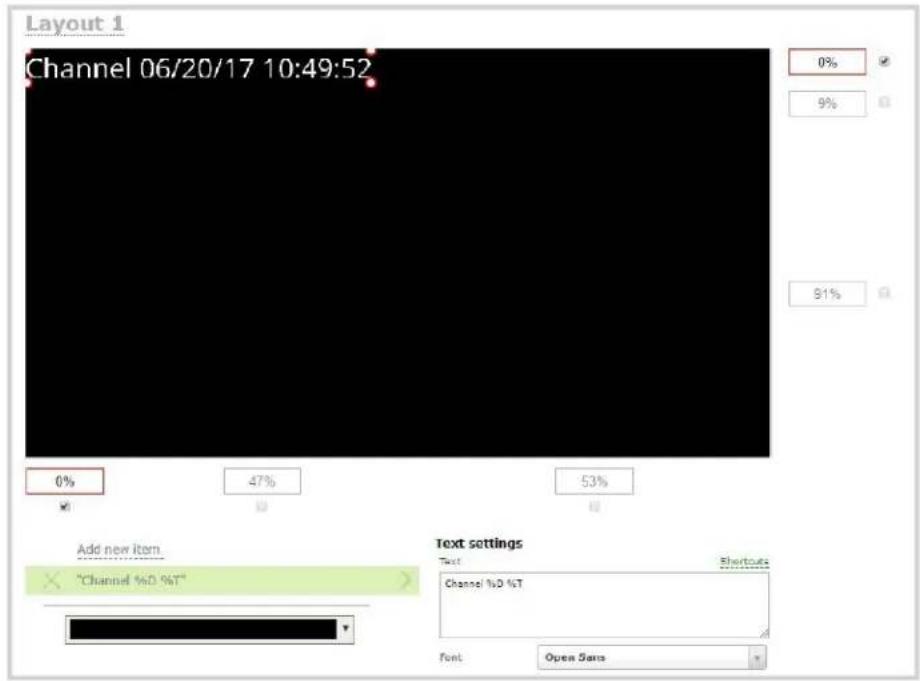
- In the Text field, specify the overlay text you want to add to the layout. Use your own text and see the Overlay text shortcut codes table provided at the end of this procedure to add any combination of the shortcut codes. Pressing Enter in the Text field refreshes the preview in the custom layout editor.
For example: Use this string:
%A %B %d, %G. Live streaming channel Auto A.
to obtain these results (Friday June 23, 2017. Live streaming channel Auto A.):
Friday June 23, 2017. Live streaming channel Auto A.
- Select the Font, Font size, and Text color. You can also change the default Line spacing in percentages. For a mono-spaced font, use Droid Sans Mono.

Limitations: The maximum supported text size is 500 px. Padding values must not exceed the frame size. Do not enter negative padding values.
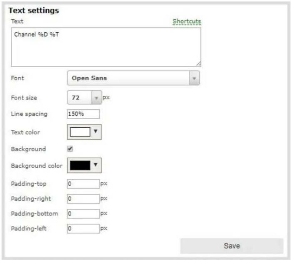
- Resize the overlay text box using the padding settings.

The handles on the corner of the overlay text box are not click-and-drag and do not resize the text box. To resize the text box, use the padding fields to add space above, below, and on either side of the text.
-
In the layout area, click and drag the overlay text box using a mouse to move the text box or enter values in the manual position value fields along the side and bottom of the layout area. See the note at the end of this procedure for more information on positioning techniques.
-
If needed, re-order the items in your layout by clicking and dragging items in the item list (under the Add new item link).
For example, if you added your overlay text before adding a video source, the video source conceals the overlay text. To fix it, drag the overlay text item above the video source item in the list, or vice-versa.
- When your layout is complete, scroll to the bottom of the page and click Save to save your work.
Table 31 Overlay text shortcut codes
| Field Value Example | ||
| date %F 2012-01-26 | ||
| year %G 2012 | ||
| month (01) %m 01 | ||
| month (Jan) | %b | Jan |
| month (January) | %B | January |
| day of the month | %d | 26 |
| weekday (Thu) | %a | Thu |
| weekday (Thursday) | %A | Thursday |
| time %T | 08:40:45 | |
| hour | %k 08 | |
| minute | %M | 40 |
| second | %S | 45 |
| millisecond | %#m | 378 |
| channel name | %c | Camera Feed 1 |
Custom overlay text (dynamic)
If you intend your overlay text to change throughout the course of your streaming and/or recording program, you can use Pearl-2's HTTP API to insert and update system-wide variables in your dynamic text field as required. For example, you may insert a system variable into your layout to represent GPS co-ordinates and then use a script to continuously update the co-ordinates contained in your variable as the exact physical location in your stream changes over time.
System variable commands can be issued at a frequency of 5 per second, and up to 6 variables may be set in a single command. After issuing a set command, all channels using the specified variable(s) are updated.
See Control with HTTP commands to learn how to configure system variables for custom overlay text.
To insert a system variable into your overlay text:
- Access the overlay text feature in your custom layout by following steps 1–5 in Custom overlay text (static) above.
For example, in the layout below, "gpsvar1" (variable name) contains the text "N103 68201 W765 29712". Inserting the variable name in the text overlay field displays the variable's value in the custom layout.
To insert the "gpsvar1" variable into your custom layout, simple type %(gpsvar1) into the Text field under the Text settings header.


If you use a non-monospaced font, the size of the text overlay changes depending on the characters in the content and the number of characters. To maintain a consistent size for the text overlay in the layout area, use a monospaced font and make sure the number of characters doesn't change.

Pressing Enter in the Text field refreshes the preview in the custom layout editor.
Other things you may want to add to your layout:
- Add a video source (custom channel)
- Add an audio source (custom channel)
- Custom crop a source
- Add an image (custom channel)
-
Delete, move, or duplicate a layout (custom channel)
-
Set the background color (custom channel)
- Rename a layout (custom channel)
A note about item positioning and sizing
There are four ways to position and size items in the layout area
- using the mouse
- using the keyboard
- using the manual positioning values with percents
- using the manual positioning values with pixels
To use the mouse:
Click and drag to move the item. Click and drag the round, red and white handles to resize an image or video source (for text overlays, just use the padding settings). Using this method you can make quick changes that are in increments of approximately 5% of the width or height of your layout area. For more refined movements, press the Ctrl key on your keyboard while dragging the item with the mouse.
To use the keyboard:
Use the arrow keys on the keyboard to move the item up, down, left or right in the layout. Changes are in increments of approximately 5% of the height or width of the layout area. Press the Ctrl key while using the arrow keys to make more refined movements. To change the size of an image or video source, press the Shift key while using the arrow keys (for text overlays, just use the padding settings). Press both Ctrl and Shift for fine-grained size control.
Using percents:
Specify a whole number, followed by a percent sign (e.g. 4%) in any of the manual positioning fields. See Resize and position layout items using percents or pixels (custom channel) for more information.
Using pixels:
If you need to specify an exact amount in pixels (rather than percent) you can type a pixel value in any of the positioning value squares followed by the characters px (e.g. 56px). You can mix and match pixels and percents changing only the boxes you want to use pixel values. At any time you can switch back to percents by typing a percent. See Resize and position layout items using percents or pixels (custom channel) for more information.
Set the background color (custom channel)
When you create a custom channel layout, you can select the background color to fill any unused space. For example you can add a color from your corporate color scheme.
To add a picture to your layout:
- Login to the Admin panel as admin. See Connect to the Admin panel.
- Follow the steps in Custom channel layout editor or Create a custom channel or layout to get to the channel layout editor.
- From the channel layout editor, click the drop down arrow next to the existing (by default black) background color; the color picker opens.
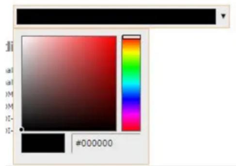
-
Pick a new color or type in an RGB value in the field; the color is updated in the layout area.
-
Click anywhere off the color picker to close the picker.
-
When your layout is complete, scroll to the bottom of the page and click Save to save your work.
Resize and position layout items using percents or pixels (custom channel)
You can position and resize layout items (images, overlay text, sources) using the percent/pixel adjustment boxes in a channel's custom layout. See Resize layout items and Position layout items.
There are 3 adjustment boxes along your layout's horizontal axis and another 3 boxes along the vertical axis. You can enter percent or pixel values into checked adjustment boxes (bordered with red) to position and resize your item(s).

Percent values are used in adjustment boxes by default, and can be converted to pixels by simply overwriting the percent value in a given adjustment box and replacing it with a pixel value.

When entering percent values, ensure the suffix "%" is added to your value (i.e. "20%").
When entering pixel values, ensure the suffix "px" is added to your value (i.e. "200px"). A layout item's total pixel dimensions are a reflection of your channel's frame size, as configured in your encoding settings (see Configure encoding).
Unchecked boxes are grayed-out in color and are not directly editable but dynamically change their values to reflect a 100% total of either the horizontal or vertical axis, depending on values entered in adjacent adjustment boxes. See the Adjustment boxes for item resizing and positioning table below for more information.

The values contained in checked boxes (bordered with red) are anchored and do not dynamically adjust their values.

Table 32 Adjustment boxes for item resizing and positioning
| Item Description | |
| 1 | The area of your layout item. The 4 red/white dots represent the boundaries of your layout item. There may be some black space between your item and its boundaries ifKeep aspect ratio when scalingis enabled (seeAdd an image(custom channel)). |
| 2 | The percentage of blank space (or number of pixels) fromleft to righton the layout's horizontal axis. (i.e. the item is displaced 20%, or 200px, to the right). |
| 3 | If using percents, this value is the item's percentage oftotal width on the layout's horizontal axis. (i.e. the item takes up 60% of the layout's width – represented by a thin red bar above the percent box).If using pixels, this value isthe item's width, in pixels, with a maximum pixel width (i.e. frame size) identified in your channel's encoding settingsConfigure encoding . |
| 4 | The percentage of blank space (or number of pixels) fromright to lefton the layout's horizontal axis. (i.e. the item is displaced 20%, or 200px, to the left). |
| 5 | The percentage of blank space (or number of pixels) fromthe bottom upwardon the layout'shorizontal axis. (i.e. the item is displaced 10%, or 100px, from the bottom up). |
| 6 | If using percents, this is the items percentage of total height on the layout's vertical axis.(i.e. the item takes up 80% of the layout's height – represented by a thin red bar to the left of the percent box).If using pixels, this value is the item's height, in pixels, with a maximum pixel width (i.e. frame size) identified in your channel's encoding settings Configure encoding . |
| 7 | The percentage of blank space (or number of pixels) from the top downward on the layout's vertical axis. (i.e. the item is displaced 10%, or 200px, from the top down). |
Resize layout items
The easiest way to resize a layout item is to use the center adjustment boxes (annotated as #3 and #6 in the image above) on each of the horizontal and vertical axes to set your item's width and height respectively. You can also use your mouse cursor to select the corners and manipulate them into the size you want. Hold the shift key while doing so to keep the frame size constant. If you need to crop your image, see Custom crop a source.

In the example above, the presenter video source is resized to 60% of the layout's width and 70% of the layout's height (with aspect ratio maintained). (Alternatively, pixels could be used to resize the layout item in a similar fashion.)
An important consideration when resizing layout items
Your item will resize automatically if both left and right (or top and bottom) adjustment boxes contain values (percents or pixels) that exceed the total of 100% (if using percents), or maximum pixel count (if using pixels) for the corresponding horizontal (or vertical) axis.
For example, if you originally set the width of an item to 50% of the layout area (or 960 pixels, assuming your item has a maximum width of 1920 pixels in this example) with no values entered in the left and right adjustment boxes (i.e. the left and right boxes are deselected), the item automatically centers itself in the layout area with the left and right percents at 25% each (remember – percents are used by default in the layout editor, even if pixels are used in adjacent boxes). Combined with the 50% (960px) width of the image, these two 25% (480px) values total 100% (1920px) of the layout's horizontal axis.
If you instead decide to enable the left and right percent boxes and change their values to 30% each (instead of the current 25%), then the image's width shrinks from 50% (960px) to 40% (750px) to accommodate the change and maintain a total layout width of 100% (1920px).

flowchart
graph TD
    A["25%"] --> B["50%"]
    B --> C["25%"]
    D["30%"] --> E["40%"]
    E --> F["30%"]

Setting the left and right (or top and bottom) percent values so the axis total among the three percent boxes exceeds 100% will always result in the center percent box value automatically reducing itself to maintain the 100% total, shrinking your selected layout item in the process.
Position layout items
Items are positioned in a custom layout by entering values into the left/right and top/bottom adjustment boxes (identified as #2/4 and #5/7 respectively in the Adjustment boxes for item resizing and positioning table above). The values entered into these boxes represent a portion of the total percentage (or pixels) of the layout's width or height.

Alternatively, you can position your layout items using the keyboard by selecting the item with your mouse cursor, and pressing the arrow keys to move the selected item by 5% in any direction.
You can also position your item with additional keyboard precision by holding Ctrl and pressing the arrow keys to nudge your item by a very small fraction in the direction of your choice.
Note that there is no one way to move and resize your layout items. The examples below are simply descriptions of one or two ways one might resize and/or position layout items.
Example 1: horizontal positioning using percents
To position your item along the horizontal axis, first resize your items if desired (as described in Resize layout items), then enter a percent or pixel value into either the left or the right adjustment box to shift your layout item.
For example, using percents to move a layout item with a 60% width as far to the right of the layout area as possible, you would need to enter 40% into the left percent box to push the item to the right. The layout item originally takes up 60% of the layout width, so this added 40% shift pushes the item as far to the right as possible (i.e. 100% of the horizontal axis).

The right adjustment box automatically sets itself to 0% to reflect that there is more no room remaining to maneuver the image along the horizontal axis any further. (Alternatively, you could reposition the image in the exact same way by instead setting the right percent box to 0%).
Example 2: vertical positioning using pixels
To position your layout item along the vertical axis, enter a percent or pixel value into either the top or the bottom adjustment box to shift your layout item downward or upward, respectively.
For example, using pixels to move a layout item that is set to 756px in height to the top of the layout while leaving a small margin of background (say 25px), you could either enter "25px" into the top percent box (to specify the small margin from the top down) or enter 27% into the bottom percent box (to specify a 27% margin from the bottom up – added to the item's 70% height this leaves a 3% margin above your layout item.)

As mentioned above, there is no one particular way to use the adjustment boxes for resizing and positioning of your layout items. The layout editor interface is flexible enough to allow you to manipulate your layout items any way you see fit. Create the perfect layout for your audience- using percents, pixels, your keyboard or any combination thereof!
Figure 1-1 An example of using pixels and percents to created a fully configured custom layout with two sources and a background image.
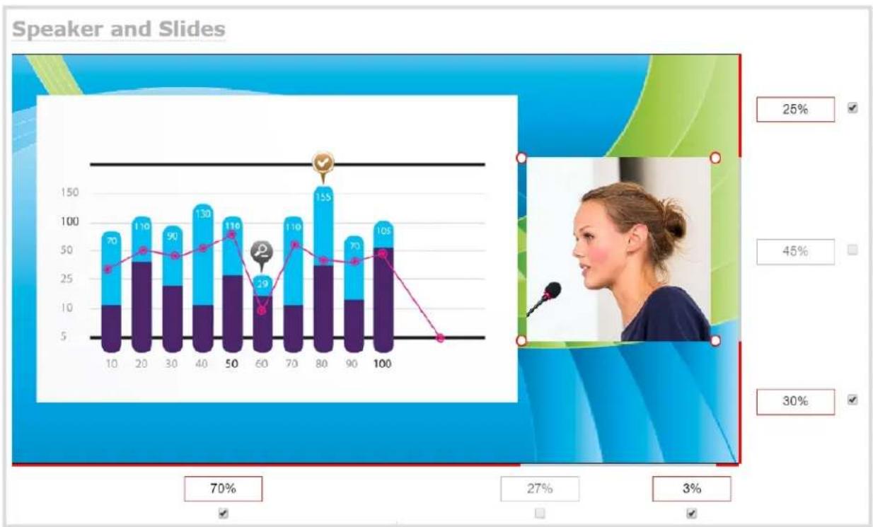
bar_line
Speaker and Slides | X-axis | Blue Bar Value | Purple Bar Value | Total Count | |---|---|---|---| | 10 | 70 | 10 | 35 | | 20 | 110 | 38 | 50 | | 30 | 90 | 24 | 46 | | 40 | 130 | 10 | 58 | | 50 | 116 | 26 | 68 | | 60 | 29 | 10 | 12 | | 70 | 110 | 10 | 62 | | 80 | 155 | 35 | 42 | | 90 | 70 | 11 | 40 | | 100 | 105 | 52 | 48 | The chart displays a stacked bar chart (top) and a line graph (bottom), both labeled with percentages (70%, 27%, 3%) and a vertical scale from -5 to +150. The top bar chart includes a note '25%' in the top-right corner, indicating the percentage value for the top bar. The bottom right shows a separate metric: '27%' and '3%'.Rename a layout (custom channel)
Layouts you create are automatically given a default name (the first one is Default!). You can keep these names, or you can edit them to something more descriptive.

If you're using the touch screen for Live video mixing / switching
You can rename any layout, even the currently active layout.
To rename a layout:
- Login to the Admin panel as admin. See Connect to the Admin panel.
- Follow the steps in Custom channel layout editor or Create a custom channel or layout to get to the channel layout editor.
- From the layout picker, click on the row of the desired layout; the layout appears in the editor below.

- From the editor, click the name of the layout; it turns red.

- Type in your new layout name and press Enter to save the new name. (Note if you click somewhere else without pressing Enter, your changes are discarded.)
Delete, move, or duplicate a layout (custom channel)
Your custom channel can have multiple layouts. The order they are listed in the Admin panel is also the order they are presented on the touch screen. It's simple to re-order layouts, remove layouts you're not using any more, and to duplicate layouts.
Reorder layouts
To move a layout:
- Login to the Admin panel as admin. See Connect to the Admin panel.
- Follow the steps in Custom channel layout editor or Create a custom channel or layout to get to the channel layout editor.
- In the layout selector, click and drag the icon with the three horizontal bars at the left side of the row to rearrange the order of your layouts.

You can delete any layout except the currently active layout.

If you're planning to use live switching, we strongly recommend you rename the channel rather than using the default channel name (Rename a channel). See the note at the bottom of this

topic to avoid streaming and recording issues resulting from adding or deleting layouts when live switching.
Delete layouts
To delete a layout:
- Login to the Admin panel as admin. See Connect to the Admin panel.
- Follow the steps in Custom channel layout editor to get to the channel layout editor.
- Click the X at the right side of the row for the layout you want to delete; the system prompts you to make sure you want to delete the layout.

- Click OK to proceed; the layout is deleted.

When using the switcher on Epiphan Live, refresh your browser if you still see a layout that was deleted. The deleted layout should disappear.
Duplicate layouts
To duplicate a layout:
- Login to the Admin panel as admin. See Connect to the Admin panel.
- Follow the steps in Custom channel layout editor to get to the channel layout editor.
- Click the double folder icon at the right side of the row for the layout you want to duplicate; a duplicate of the layout is added at the bottom of the list.

Important note for channels with multiple layouts
By default (and historically), Pearl-2's channels are named automatically based on the content in the channel. When a channel has only one layout, and that layout has only one source (regardless of whether or not there are pictures or overlays in the layout), the channel name is the same as the source name.
For example: By default, a channel with one layout that has HDMI-A in it will be named HDMI-A.
When you add a second layout to a channel, the channel name changes to a generic name Channel X (where X is the channel index number). Normally this wouldn't pose any problem, but the changing name does have some side effects: the stream is stopped and restarted, and the channel's recorder (if recording) is stopped and a new file is started.
Furthermore, when you delete layouts in a channel until there is only one layout (with one source) left, the channel name reverts to the source name.
To avoid any issue with changing channel names on channels where you'll have more than one layout, we strongly recommend you rename the channel to a custom name (Rename a channel. This will ensure no automatic channel name changes.
Delete an uploaded image
Images used in custom channel layouts are stored on the system hard drive. You can delete an image after you are done using it, or to when performing general housekeeping duties on the system.
To delete an uploaded image:
- Login to the Admin panel as admin. See Connect to the Admin panel.

If the image is used as part of the layout for any channel, select a different image or no image by using the drop-down list in the Picture settings box within that channel's layout before deleting the file using the steps below.
- Click Branding Content under the Configuration menu; the configuration page opens.

- Click Remove; a confirmation dialog box opens.
- Click OK; the dialog box closes and the image file is removed from the configuration page.
Configure encoding
You can modify the encoding settings for each channel you create. These settings let you perfect your stream by selecting the right frame size, bit rate, audio/video codecs and more.
This section covers the following encoding topics:
- Configure video codec
- Configure frame size
- Fine tune stream settings
- Configure audio codec
- Multi-Encoding
• Codec and file format compatibility
Configure video codec
To configure encoding:
- Login to the Admin panel as admin. See Connect to the Admin panel.
- Click the Encoding link for your channel; the encoding configuration page opens.
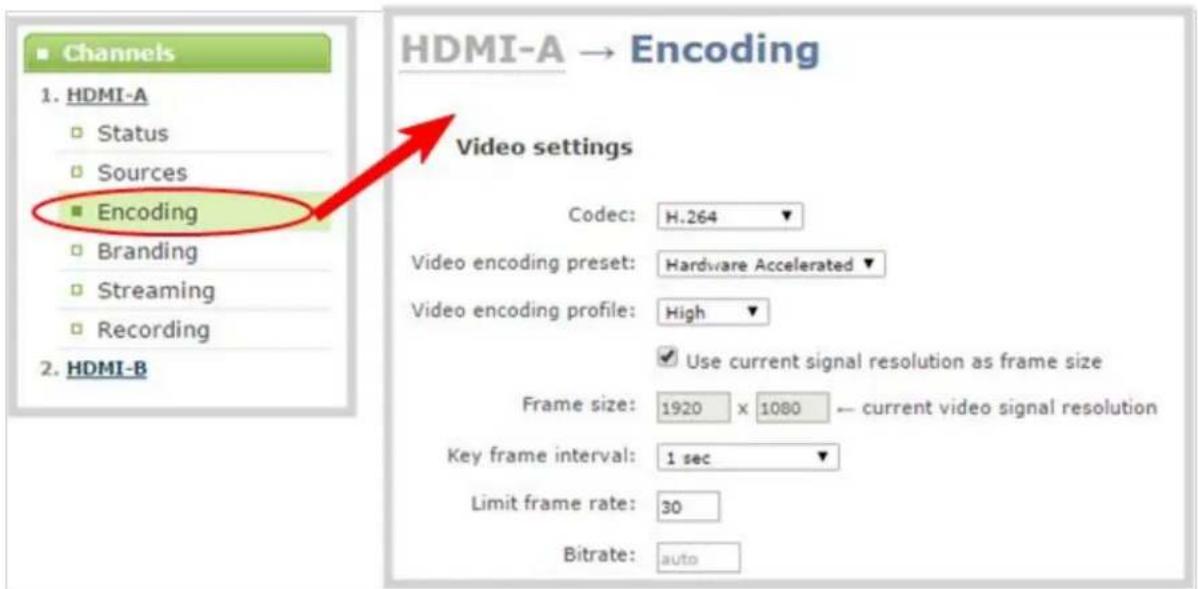
- Click the Codec drop-down menu to change the size and speed of the compression and decompression and the quality of the image. Choose one of the following options from the Codec drop-down menu.
| Value Description | |
| H.264 | H.264 is the default value and provides high quality video while using low bandwidth. This is the preferred codec for the system. |
| Motion JPEG | This is suitable for live streaming and video, however may have low quality images while using high bandwidth. Motion JPEG does not support audio. |
-
If the selected codec is Motion JPEG, you can configure the Page refresh time. Specify a time in a seconds.
-
If the selected codec is H.264 (default), click Video encoding preset to define how the video stream is encoded. Choose one of the following:
| Value Description | |
| Hardware Accelerated | This is the default H.264 encoding preset. Choose this setting for best performance. |
| Software | This matches the default from previous generations of Epiphan products. Choos this only if you need software encoding or X.264 encoding to match results created with previous generations of Epiphan products or firmware. |
- If the selected codec is H.264 (default), click Video encoding profile to limit or include video formats that are supported. Choose one of the following:
| Value Description | |
| Baseline | Choose this option when streaming to an application that requires robustness and cannot tolerate data loss, for example video-conferencing. |
| Main Choose this option for standard-definition broadcasts. This is the default. | |
| High | Choose this option when video is viewed for broadcast and disk storage applications, particularly for high definition television application such as Blu-ray disk storage format and HDTV broadcast service. |

Video encoding profile and preset can be set only when the H.264 codec is selected.
- If all your changes are complete, scroll to the bottom of the page and click Apply.
Configure frame size
By default, for channels with only one layout and when that layout has only one video source, your Pearl-2 automatically uses the incoming source frame size as the stream frame size. Frame size greatly affects the amount of bandwidth needed to transmit your stream. The larger the frame size, the more bandwidth you need to stream it. So you may want to keep the frame size the same as your source, or you may want to apply upscaling, downscaling, stretching, or black bar framing, depending on your needs.
For example:
- if the input signal resolution is 1920 × 1080 (a 16:9 aspect ratio)
• and stream frame size is set to another 16:9 frame size such as 1280×720,
the smaller stream frame size causes the system to downscale the image and use less bandwidth to transmit.
Or if you have a widescreen/HD format source but need a 4:3 output frame size, you can add black bars to the top and bottom of the frame.

The system is designed to provide scaling, however for the best overall system performance (particularly when reaching maximum system capacity), configure your source to provide the correct frame size and avoid scaling.
To configure your stream's frame size:
- Login to the Admin panel as admin. See Connect to the Admin panel.
- Click Encoding for the your channel; the encoding configuration page opens.
- Scroll to the Frame size section.
- Perform one of the following steps:

Using current signal resolution as the frame size only works for channel layouts with a single source. If you're using multiple sources, follow the steps below to set your frame size.
a. Check the Use current signal resolution as the frame size check box. Enabling this feature greys out the other frame-size configuration fields. The system automatically streams at the frame size of the input signal.
Frame size:
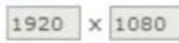
← current video signal resolution

If you change the frame size (resolution) of the input signal after streaming (or recording) begins your may see interrupted streaming and recording. Enabling this feature is not recommended for systems where input resolution is changed frequently.
b. Change the frame size, follow the steps below.
- Set the Frame size values to reflect the dimensions required for your stream. Some suggested values cover popular resolutions of cameras and display devices such as monitors, but you may also specify something custom:
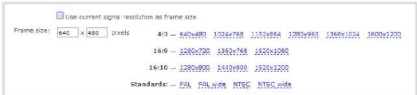
a. Uncheck Use current signal resolution as frame size.
b. Type a frame size in the field; or
c. Select an option from the sizes shown, the dimensions will appear in the frame size field.

Scaling occurs automatically (no extra configuration needed) when you make the dimensions larger, smaller, or a different aspect ratio than the source.

If you have unchecked all the manual resizing and positioning boxes in the custom layout editor and you downscale the video source using the frame size setting on the Encoding tab (for example, select 1280×720 frame size for a full HD video source), then the source appears cropped within the frame instead of scaling to fit the frame.

If your channel has a layout with only one source and your source and stream aspect ratios differ, when viewing that layout, your source is centered in the frame and matte bars are added to the top and bottom or left and right sides to make up the difference. See Remove black bars (matte) from the video.
- If all your changes are complete, scroll to the bottom of the page and click Apply.

If you plan to use layout switching during a live stream, it's best to choose a fixed layout size. This avoids causing the stream restart due to frame size change when you switch between single-source layouts that use frame sizes.
Fine tune stream settings
Along with video/audio codecs and frame size, there are other configurable stream settings that affect quality and bandwidth. Like with frame size selection, values for these settings can be a tradeoff between bandwidth available and quality for stream viewers.
A table at the end of this section provides additional guidance for the settings
To fine tune your stream's settings :
-
Login to the Admin panel as admin. See Connect to the Admin panel.
-
Click Encoding for your channel; the encoding configuration page opens.
-
Scroll to the Key frame interval setting.
-
Click the Key frame interval drop-down box to choose how often a key frame (a frame that contains all the pixels) is sent when streaming the video. The longer the key frame interval the smaller the video file size, and vice versa.
-
If desired, change the Limit frame rate. The default should be adequate in most applications. While decreasing the limit may improve system performance, you may need to test different values to balance video smoothness and processing power.
-
If using H.264 video codec, you can increase or decrease image quality by increasing or decreasing the target Bitrate value. Video with a high level of motion and high resolution, such as a sporting event, requires a high bitrate.
-
If all your changes are complete, scroll to the bottom of the page and click Apply.
Table 33 Stream settings guidance
| Setting Description | |
| Key frame interval | The key frame interval feature specifies how often a key frame (a framethat contains all the pixels) is sent when streaming the video. This setting also impacts how quickly a video moves through the frames when a viewer uses the search function of their media player.Increasing the number of seconds between key frames can significantly reduce your bandwidth and system resource usage with minor impact to your video quality. A good rule of thumb is to keep the interval between 3 seconds and decrease the key frame interval as the motion increases. Try different settings and note changes in the video quality. If your video quality is poor and jittery you may need to decrease the interval between key frames. If you have unlimited bandwidth and system resources you can choose an option to stream key frames only. |
| Frame rate | Frame rate reflects the number of images captured by the device per second. Reducing the frame rate reduces bandwidth usage, and vice versThe system's ability to maintain a set frame rate is based on several factors, for example:overall system load affects the ability for the device to process pixels;available network bandwidth;the source and stream frame size (resolution);the type of motion that is captured; andnumber of users accessing the stream.When adjusting the frame rate, you may need to try different values to achieve the best outcome. |
| Bitrate | In general, higher bitrate mean higher image quality in the stream, at the cost of higher bandwidth needed to transmit it.For comparison against something you are likely familiar with, an HD Blu-ray video is typically in the range of 20 Mbps, standard-definition DVD is usually 6 Mbps.If you don't know what value to use, a good place to start is 5000 kbps (slightly less than a typical DVD). Test to see how this works for your viewers and adjust. |
Configure audio codec
If your channel sources included audio (see Create a simple channel or Create a custom channel), your stream will by default use the AAC audio codec at 48 kHz. You can modify this setting to best match your streaming or post-processing needs.
To configure your stream's audio codec :
- Login to the Admin panel as admin. See Connect to the Admin panel.
- Click Encoding for the your channel; the encoding configuration page opens.
- Scroll to the Audio settings section.

- Ensure the Enable audio checkbox is checked.
- If the default audio format AAC 44KHz, stereo, 320 Kbps is not desired, click the Audio format dropdown menu to select an audio codec. A table at the end of this procedure gives details about each option.
- Click the Audio channels drop-down menu to choose mono (1 channel) or stereo (2 channels).

If desired, you can choose Mono to have left and right stereo channels combined and streamed together (i.e. when listening to the streamed audio, the same blended sound will come through both the left and right channels).
If you have only one mono analog input, use the left XLR / RCA jack and select mono encoding to have the same sound come from both the left and right channels. (If stereo sound is chosen, the sound will only come through on the left channel.)
- Select an Audio bitrate from the drop-down menu. The table at the end of this procedure gives some guidance on audio bitrates.

For stereo audio, we recommend 256 kbps or 320 kbps.
- If all your changes are complete, scroll to the bottom of the page and click Apply.
Table 34 Audio codecs and bitrate guidance
| Value Description | |
| AAC | AAC is the default audio codec.This codec is comparable to MP3, and may have better sound quality with a similar bit rate. Supported values are 16, 22, 44 and 48K kHz. Most digital signals (HDMI or SDI sources) use 48 kHz audio缺点ing the encoded level with the source level provides the best sound quality by avoiding audio resampling. For analog signals, 44 kHz provides higher sampling.The maximum bitrate for mono encoding of a 44 kHz signal is 264 kbps. For stereo, 320 kbps is supported. Note that lower bitrates (e.g. 32 kbps) with a 44 kHz signal may result in distorted audio. |
| MP3 | MP3 provides a common audio format for audio storage.Supported values are 22 kHz, 44 kHz and 48 kHz. Most digital signals (HDMI or SDI sources) use 48 kHz audio. Matching the encoded level with the source level provides the best sound quality by avoiding audio resampling. For analog signals, 44 kHz provides higher sampling. Flash (FLV) doesn't support 48 kHz MP3 audio. When selecting this value you'll need to use a media player to preview your channel. Flash (FLV) doesn't support 48 kHz MP3 audio. When selecting this value you'll need to use a media player to preview your channel. |
| PCM | Pulse Code Modulation (PCM) is a standard for digital audio in computer and other devices such as, digital telephone systems.Most digital signals (HDMI or SDI sources) use 48 kHz audio. Matching the encoded level with the source level provides the best sound quality by avoiding audio resampling. For analog signals, 44 kHz provides higher sampling. Flash (FLV) doesn't support 48 kHz PCM audio. When selecting this value you'll need to use a media player to preview your channel. Flash (FLV) doesn't support 48 kHz PCM audio. When selecting this value you'll need to use a media player to preview your channel. |
Codec and file format compatibility
Not all streaming and recording protocols support all combinations of video and audio codecs. Use the tables below to determine what settings work for your streaming and recording needs.
The following table displays the compatibility between the video/audio codecs and formats supported for streaming.
Table 35 Video/audio codecs and formats for streaming
| Video Codec selected Audio Codec selected RTSP FLV MPEG-TS | MJPEG | ||||
| H.264 No audio codec | √ √ | √ | |||
| H.264 PCM | √ | √ | |||
| H.264 MP3 | √ √ | √ | |||
| H.264 AAC | √ √ | √ | |||
| MJPEG | No audio codec | √ | |||
The following table displays the compatibility between the video/audio codecs and formats supported for recording.
Table 36 Video/audio codecs and formats for recording
| Video Codec selected | Audio Codec selected | MP4 and MP4-Fragmented | AVI | MOV | MPEG-TS |
| H.264 | No audio codec | √ | √ | √ | √ |
| H.264 | PCM | √ | √ | √ | |
| H.264 | MP3 | √ | √ | √ | √ |
| H.264 | AAC | √ | √ | √ | √ |
| MJPEG | No audio codec | √ | √ | √ | √ |
Multi-Encoding
Pearl-2, in addition to multi-publishing, allows for a process called multi-encoding. Use it if you wish to:
- Record a video at a high bitrate and frame size while streaming the same video online at a lower encoding settings,
- Record channel while also sending two or more streams of the same channel at different encoding settings for CDNs that don't use adaptive bitrate,
• Or record the same channel simultaneously in 4K and full HD.
Multi-encoding has versatile and broad-use functionality.
As an example, take a scenario where you want to record a video at 1080p and 8 Mbps, while simultaneously streaming the same video online 720p and 1 Mbps.

flowchart
graph TD
    A["Laptop"] --> B["My Slides"]
    B --> C["Analog A"]
    C --> D["LUMiO 12x"]
    D --> E["Local loopback"]
    E --> F["RTSP"]
    F --> G["Add as RTSP source"]
    H["Program Out for recording"] --> I["Recording - 1080p, 8 Mbps"]
    H --> J["Video sources - HDMI A, SDI A"]
    H --> K["Audio sources - Analog A"]
    L["Program Out for streaming"] --> M["Streaming - 720p, 1 Mbps"]
    L --> N["Video sources - RTSP source"]
    L --> O["Audio sources - RTSP source"]
Follow these steps:
- Login to the Admin panel as admin. See Connect to the Admin panel.
- Create Channel 1 with your video and audio inputs. Add all your live switching layouts.
- Copy the RTSP stream link from Channel 1's Status page.

- Add a new RTSP source using the link copied in the previous step.
- Change the pasted IP address to use localhost or 127.0.0.1 as the IP address.
- Set Preferred transport to TCP.
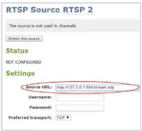
- Create Channel 2 with just one layout and add the new RTSP source you just added, stretch it to fill the full screen.
- For Channel 2's audio source, choose the same RTSP source.
- Set encoding and streaming settings for channel 2.
Using this process, you can again use the same video you're recording on Channel 2, and stream it at a different bitrate and frame size.
For a different process that helps you accomplish similar goals, you can learn about a multi-publishing Stream
Add channel metadata
Adding company information to metadata is an easy way to identify and copy protect your broadcast or recording.
This section describes the following topics for customizing your channel:
- Add channel metadata
- Remove metadata from a channel

Previous firmware versions gave the ability to configure "No Signal" images per channel. "No Signal" images are now done on a per-source basis instead. See Add a No Signal image to a source.
Add channel metadata
Using the Branding feature, you can apply a logo to your channel and specify the following meta data that the media player displays for your viewers:
• title of the presentation;
- company website;
- presenter's name;
• copyright date or other labels such as proprietary information, preliminary etc; and
• additional information about the broadcast, such as time of the broadcast, or change to the schedule.
To apply channel metadata:
- Login to the Admin panel as admin. See Connect to the Admin panel.
- From the Admin panel, select a channel; the menu expands.
- Click the Branding link for your channel; the Branding configuration page opens.

-
Enter metadata such as: presentation title, presenter name(s), any copyright dates and additional information about the broadcast that you want the viewer to know. How metadata is displayed depends on the media player. For example VLC stores the metadata in a media information file, while other media players scroll the text horizontally from right to left along the bottom of the media player window, similar to a ticker message bar.
-
Click Apply.
Remove metadata from a channel
- Login to the Admin panel as admin. See Connect to the Admin panel.
- From the Admin panel, select a channel; the menu expands.
- Click the Branding menu option; the Branding configuration page opens.
- Scroll to the Content metadata section.
- Click the Author, Copyright or Comments field.
- Highlight the text and press delete on the keyboard. The field is empty.
- Click Apply.
Preview a channel
While configuring a channel in the Admin panel, you may want to open a live preview of the channel in another tab or browser window so you can see the changes as they are applied. Choose one of the following options to preview your channel:
• Preview a channel from the Info page
• Preview a channel from the Status page
• Preview all channels at once

You can also preview channels using the Epiphan Live control interface. See Configuring Dashboard panels for visual confidence monitoring for more information.
Preview a channel from the Info page
The system's Info page displays links for previewing your channel(s). This fast and simple method allows you to see link for all the streams in a single location.
To preview a channel from the Info page:
- Login to the Admin panel as admin. See Connect to the Admin panel.
- From the Admin panel, click Info from the Configuration menu option; the information window opens.
Pearl-2 B7E5C813 info
Firmware
Version: 4.0.0c Revision: 35719_1771 Date: 2016-08-22
Hardware
CPU board: SKYBAY (Default string)
Channels
| # | Channel name | Status | Video source | Audio source | Stream | Bitrate | Actual bitrate | Frame size | FPS / Actual FPS | Port | |
| 1 | HDMI-A | ok | HDMI-A | HDMI-A Audio | H.264+PCM | auto | 1621 kbps | 1920x1080 | 30 / 30.0 | 8000 | View |
| 2 | HDMI-B | ok | HDMI-B | HDMI-B Audio | H.264+PCM | auto | 1615 kbps | 1920x1080 | 30 / 30.0 | 8001 | View |
| 3 | HDMI4K-A | ok | HDMI4K-A | HDMI4K-A Audio | H.264+PCM | auto | 1617 kbps | 1920x1080 | 30 / 30.0 | 8002 | View |
| 4 | HDMI4K-B | no signal | HDMI4K-B | HDMI4K-B Audio | H.264+PCM | auto | 3578 kbps | 1920x1080 | 30 / 30.0 | 8003 | View |
| 5 | SDI4K-A | no signal | SDI4K-A | SDI4K-A Audio | H.264+PCM | auto | 1599 kbps | 1920x1080 | 30 / 24.8 | 8004 | View |
| 6 | SDI4K-B | no signal | SDI4K-B | SDI4K-B Audio | H.264+PCM | auto | 1642 kbps | 1920x1080 | 30 / 30.0 | 8005 | View |
Overall system load: 20%
- Scroll to the channel you want to preview.
- Click View; the corresponding channel is displayed in the window.
Preview a channel from the Status page
The channel's status page gives a wealth of information about the channel, including bit rate, frame size, a snapshot of the channel and links to preview the channel.
To preview a channel from the Status page:
-
Login to the Admin panel as admin. See Connect to the Admin panel.
-
Click the link for Channel you want to preview, the menu expands.
- Click Status; the channel's Status page opens.
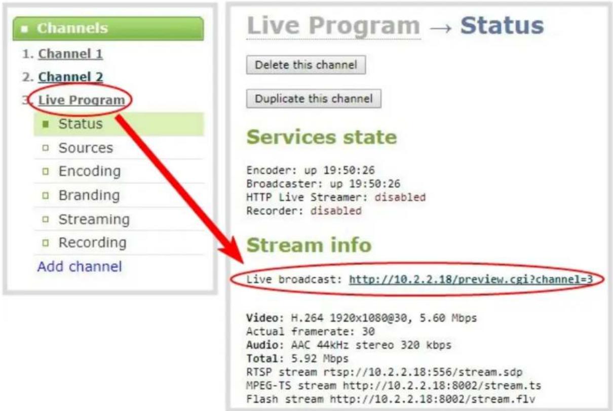
- Scroll down to see the snapshot.
- Right-click the Live Broadcast link and select Open in a new Tab or Open in a new Window; a tab or window opens displaying a preview of the channel.
Preview all channels at once
Pearl-2 has a special preview mode that lets you see all configured channels at once.

The resulting web page can be very large. You may wish to be aware of your web browser's zoom hot keys. Many browsers will zoom out with Ctrl-- (control minus) and zoom in with Ctrl-= (control equals).
To preview all channels at the same time:
-
Open a new browser window.
-
Type the following string into the address bar of your web browser on your admin computer (ipaddress is the IP address of your Pearl-2).
http://
For example: http://172.20.1.33/preview.cgi?
- Press Enter, the preview web page appears displaying the content of all active channels.
Rename a channel
By default, channels are created with the same name as their source - until a second layout or a second source is added to the channel, at which time the channel is renamed Channel X where X is the index of the channel. However there may be circumstances when you want to create a distinct name for the channel to reflect the source(s) it contains.

Auto channels initially have the channel name Auto A and Auto B, but if you change the source to something other than an automatic source, the name of the channel changes to reflect the new source.
To rename a channel:
-
Login to the Admin panel as admin. See Connect to the Admin panel.
-
From the Admin panel, scroll to the Channels menu option.
-
Click on the channel you want to rename; the menu expands.
-
Click any link for the channel; the corresponding channel status or configuration page opens.

You can change a channel's name from any of it's configuration pages.
-
Click the channel name at the top of the channel configuration page; the name text becomes red to indicate that it is editable.
-
Highlight the old name and press backspace or delete on the keyboard.
-
Type the new name, using alphanumeric characters. It's recommended (but not mandatory) that you use underscores to separate words, if needed.
-
Press Enter on the keyboard. The name is updated at the top of the screen and in the list of Channels in the navigation menu.

You must press the Enter key on the keyboard for the change to take effect.
Duplicate a channel
You can duplicate any channel you've created. All settings in the channel you duplicate are recreated.
To duplicate a channel, follow the steps below.
- From the Admin panel, scroll to the Channels menu option.
- Click the channel you want to delete; the menu expands.
- Click Status; the Status page opens displaying the service state and stream info for the channel.
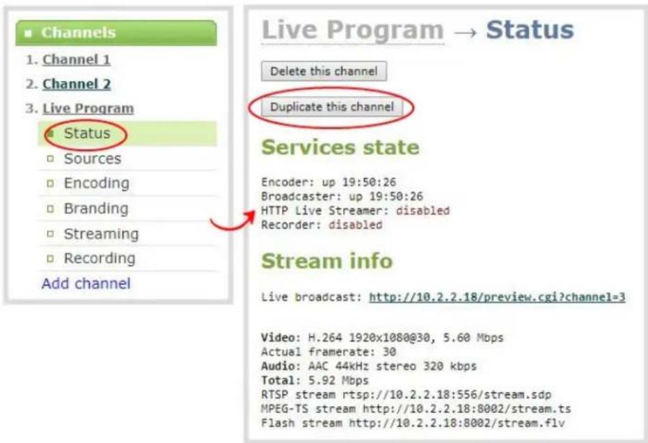
- Click Duplicate this channel. The duplicate channel is created and assigned the next channel number in your list of channels.
Delete a channel
From time to time you may want to clean up the list of channels, and remove channels that are no longer used. The following steps describe how to delete a channel. Deleting a channel does not delete the input source configuration, however it deletes any recorded files for the channel.
To delete a channel, follow the steps below.
- From the Admin panel, scroll to the Channels menu option.
- Click the channel you want to delete; the menu expands.
- Click Status; the Status page opens displaying the service state and stream info for the channel.
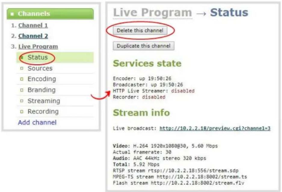
- Click Delete this channel; a confirmation dialog box appears to remind you that all recorded files for this channel will be removed.

You cannot undo this command.
- Click OK to continue or Cancel to stop. If you proceed, a message indicating that the channel was successfully deleted appears at the top of the page.
Live video mixing / switching
Pearl-2 supports live video mixing (also known as live video switching) while you are capturing, streaming and recording. Video mixing is a great way to create dynamic content for your viewers and recordings. With Pearl-2, switching happens in less than half a second (< 500 ms)!
This means you can start your stream with a video source showing a countdown, move to a single-camera view, then switch between multiple cameras or multiple layouts with more than one source, and end again with a thank you message for attendees. (Layout switches made in your channel are reflected in both the live stream and recording.)
For example, your stream could look like this:

Before you can switch between layouts, make sure you have your custom channel with layouts created. See Create a custom channel or layout.
Now on to the fun part!
There are three ways to perform live switching. You can use the Admin panel, the touch screen or the Epiphan Live control interface.

Performing live switching in one interface (e.g. Epiphan Live) does not dynamically update the visuals in the other interfaces (e.g. the Admin panel and Pearl-2's touch screen). All other interfaces must be manually refreshed to accurately reflect the current live switching layout information.
Switching / mixing using the touch screen
Switching live video inputs, or video mixing, is simple and intuitive using Pearl-2's touch screen. Simply scroll to the channel you want to work on, select the layout switching mode and apply the layout you want to use.
By default layout control is enabled for the touch screen, but it's possible your touch screen has been configured by the administrator to prevent layout switching, or even channel monitoring. If the instructions below don't work for you, see Block (or allow) recording, streaming and switching from the touch screen for details on enabling layout control by the touch screen.
To switch video using the touch screen:
- If needed, touch the screen once to turn it on.
- If needed, touch your channel in the grid view to change it to individual view.
- If needed, touch the screen once to enable controls on the screen.
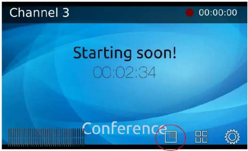
- Touch the button to start layout switching mode; the screen changes to display your layouts.

flowchart
graph TD
    A["Press back to return to the individual channel view"] --> B["Preview"]
    C["Touch apply to make your preview layout the live layout"] --> D["Live area (live layout)"]
    E["Your layouts (touch to send to preview)"] --> F["Start"]
    F --> G["singleCam"]
    G --> H["slides"]
    I["Colored-coded frames: Red: currently active (live) Green: currently in preview (on deck) Grey: idle"] --> J["Starting soon! 00:02:3/"]
    K["Starting soon! 00:02:3/"] --> L["Conference"]
    M["Start"] --> N["singleCam"]
    O["Start"] --> P["singles"]
    Q["Start"] --> R["Conference"]
    S["Start"] --> T["Live area"]
- Initially, your live layout (which is displayed on the right side) is the same as your preview, or on deck, layout. It appears in the list at the bottom with a green bar on the frame to show it is in preview. Touch any other layout; the touchscreen updates to show your new layout in preview.

- Both the live layout and the preview layouts update at a reduced frame rate to the live stream, but fast enough that you can see what is happening.
- When ready, touch Apply to cause the layout currently in preview to become live; the switch happens and your screen is updated.
- Continue to switch layouts as needed for the duration of your event or recording.
- Touch Back to return to the individual view screen at any time or when you are done video mixing.
Switching / mixing using the Admin panel
Switching live video inputs, or video mixing, is fast and easy using the Admin panel. For best results, you may wish to be in a location where you can see the live action, and have a solid understanding idea of what is in each of your layouts. Good layout names can help with this. See Rename a layout (custom channel).
To do live video mixing:
- Login to the Admin panel as admin. See Connect to the Admin panel.
- Follow the steps in Custom channel layout editor or Create a custom channel or layout to get to the channel layout editor.
Channel 3 → Sources

-
The currently active layout has a red button in the right-most column.
-
Touch the empty circle for another layout to make it the active layout; the layout changes in the live stream (and recording), and the new row gets the red button.
Channel 3 → Sources

- Continue to switch layouts as needed for the duration of your event or recording.
Switching / mixing using Epiphan Live
Epiphan Live is a simple and easy to use interface which is used for confidence monitoring, streaming/recording control and live switching. (See Epiphan Live for more information.)
Within Epiphan Live, the Switcher view allows you to seamlessly switch between a channel's custom layouts while live streaming and/or recording.
To switch a layout while live streaming and/or recording using Epiphan Live:
- Log in to Epiphan Live; the Dashboard view opens by default. See Accessing Epiphan Live.
- Click the Menu icon in the upper-right corner of the Dashboard screen and click Switcher to navigate to the Switcher interface.

- Click the text box next to the "Switcher" header and select your desired channel from the dropdown list (the text box will appear blank if this is your first time configuring the Switcher interface). Note that in the channel dropdown list, channels containing only a single layout are grayed-out and are not selectable.
After selecting your channel from the dropdown, the Switcher interface appears with all of your channel's layouts displayed along the bottom of the page.
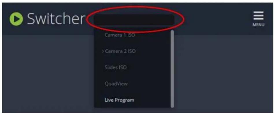
The layout currently being streaming and/or recorded is displayed in the Live view panel on the right side of the interface (see Understanding the Switcher interface).
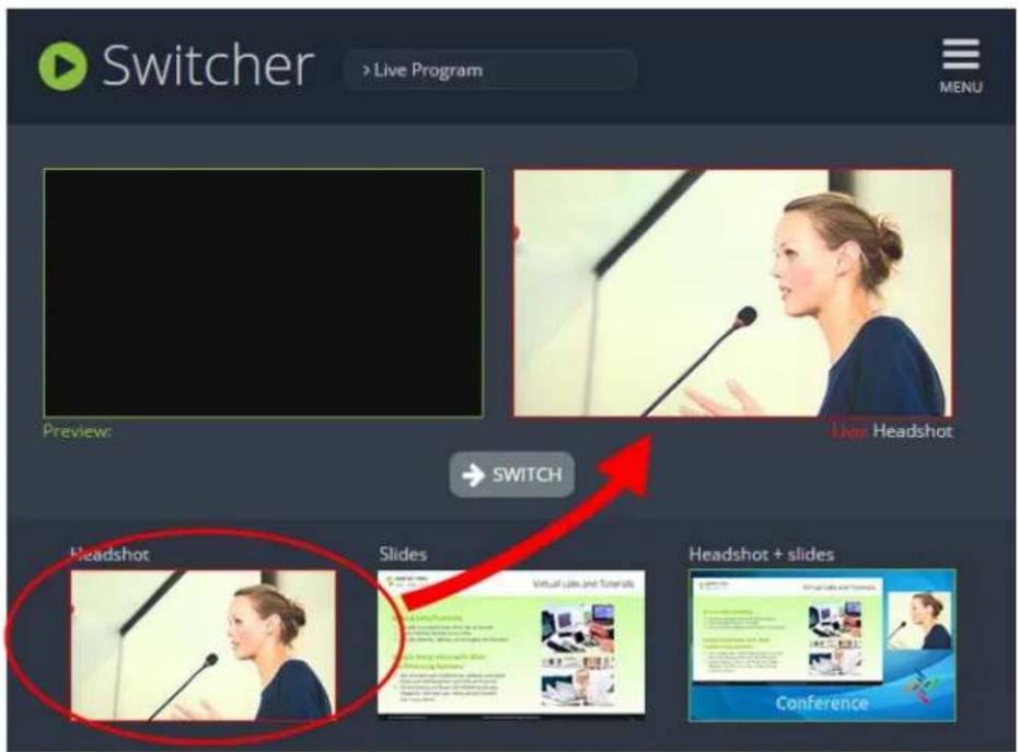
- Click on your desired layout at the bottom of the page to dock it in the Preview panel. This is the layout that will be switched into your live stream/recording.

- Click the Switch button in the center of the screen to switch your layout in the Preview panel into your live stream/recording.
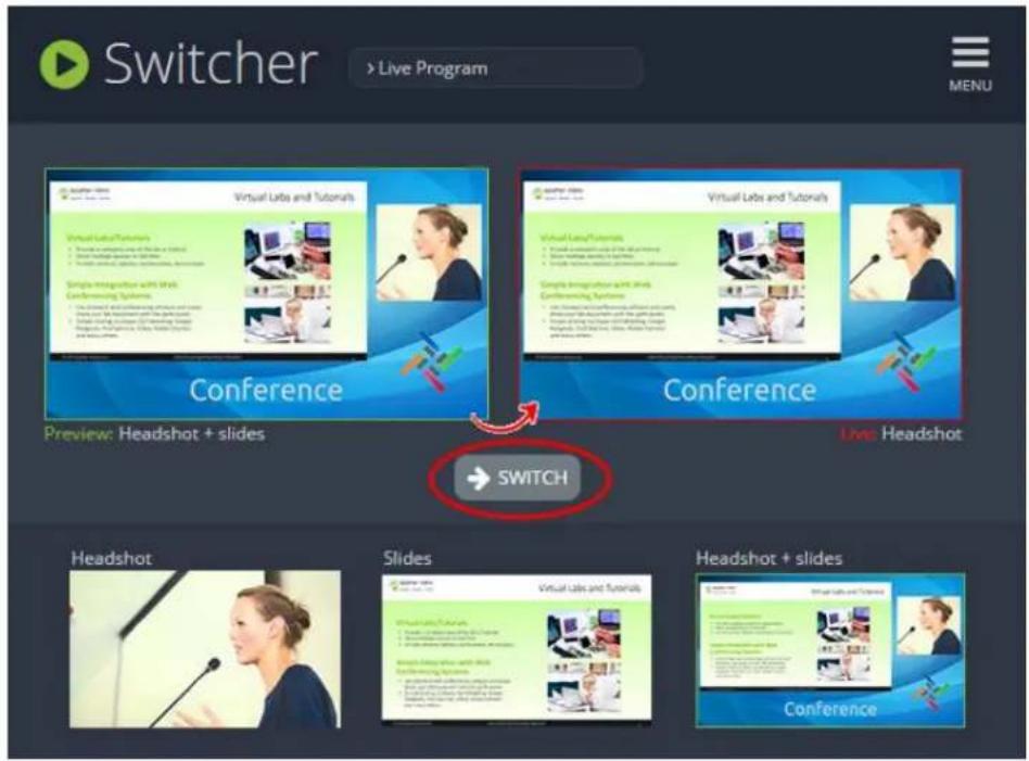
What is a source?
A source can be an image, video, or audio from a camera, a computer screen or any device that provides any HDMI, DVI, SDI, USB video signal and audio signal output.
You can also connect RTSP sources such as IP cameras and other Pearl-2 systems to your Pearl-2 over a network using the Admin panel. See Connect an RTSP source.
Video sources
The Admin panel automatically discovers all video source ports and displays them in the Sources section of the Admin panel. RTSP sources need to be added manually to display in the Sources section (see Connect an RTSP source). When an RTSP source is added, a corresponding audio sources is always added to your custom layout editor (regardless of whether or not the RTSP stream actually contains any audio). See Add an audio source (custom channel).

Video sources are also displayed on the Epiphan Live control interface. See Monitoring video and audio sources for more information.
Each video input on the back of the system is identified by an A or B and input type (HDMI, SDI, USB video). For example the SDI input labeled A appears as SDI-A in the Web UI. Input sources display their captured images on their respective source page. It is a good practice to view the images from each source to confirm what is captured. See below.
When a source is connected, the system automatically detects and adjusts the image capture settings at start up and continues to adjust every 60 seconds during operation (interval is configurable). The system's goal is to produce the best quality captured image given the source equipment used. Generally no further configuration is needed.
If there is no source connected to a specific port or no input stream being transmitted from a connected RTSP source, then the default "No Signal" image will display in any channel where the source is used. You can use Pearl-2.'s default "No Signal" image for your sources, or you can create your own custom "No Signal" image for your channels to enhance branding and add professionalism to your display. See Add a No Signal image to a source .
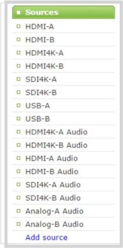
Audio sources
Pearl-2's Admin panel also automatically discovers all audio sources and displays them in the same section, with the exception of RTSP audio sources. When an RTSP input stream is connected to your Pearl-2, a corresponding audio source is automatically added to the list of audio sources for your channels, even if there is no audio in the RTSP stream (see Add an audio source (custom channel) for more information).
Audio input devices such as a microphone and portable music players can send audio signals to Pearl-2 using the XLR or RCA audio input ports at the back of the system. Audio is also supported via HDMI and SDI.
This chapter covers the following sections:
- Connect a source
- Connect an RTSP source
• List of tested RTSP-based IP cameras - Connect an AV.io video grabber
-
Preview a source
-
Rename a source
- Configure a source
- Adjust audio gain (analog audio) and delay
- Add a No Signal image to a source
Connect a source
You can physically connect HDMI, DVI, SDI, USB video sources to Pearl-2 at any time, either before or after the system is powered on. Similarly you can disconnect a source from a port and even connect a different source at any time.
You can also connect wireless RTSP sources to your Pearl-2 over a network. Both the RTSP source device and your Pearl-2 need to be powered on to establish a connection. See Connect an RTSP source for more information.

Changing the source that is being streamed or recorded can result in the recording stopping or the stream frame size changing depending on how your channel is configured.
If the frame size changes, viewers may be disconnected and need to re-connect to the stream.
Connect sources to the following input ports on your system:
Table 37 Cable and port connections
| Source type Input port | |
| SDI SDI port | |
| HDMI (HDCP-protected) or DVI HDMI port | |
| USB video USB 3.0 port (rear) | |
| RTSP | No input port. RTSP sources are connected to your Pearl-2 wirelessly over a network and are configured using the Admin panel. See Connect an RTSP source to learn how to connect an RTSP source. |
| Audio Audio input port (XLR or RCA) | |
Connect an RTSP source
You can connect RTSP sources such as IP cameras and other Pearl-2 systems to your Pearl-2 over a network using the Admin panel.
RTSP video encoding is supported with H.264 video codec and MP3 or AAC audio formats.

Decoding a 1080p RTSP signal at 30 fps consumes approximately 10% of your Pearl-2's CPU power. If an RTSP source is connected but unused in any channel, Pearl-2 decodes only key frames to preserve CPU resources.
To synchronize timestamps between your RTSP source and your Pearl-2, the same time synchronization server should be used for both devices. It is recommended that you configure an NTP server on your Pearl-2 and use Pearl-2 as a time synchronization server for your RTSP source. See Configure synchronized time (NTP, PTP v1 and RDATE).
Due to the nature of external encoding devices such as RTSP sources, it is possible for the timestamps between your Pearl-2 and your RTSP source to gradually become out of sync. If there is a 2500 -3000 ms timestamp difference between your RTSP source and your Pearl-2, then a "no signal" image will display and your RTSP source will not stream any audio. Re-connecting your RTSP source resets any time synchronization issues.
You can use your another channel on your Pearl-2 as an RTSP loopback. When doing so, replace the IP address in the RTSP link with localhost or the address 127.0.0.1 - this gives better results.
To connect an RTSP source to your Pearl-2:
- Login to the Admin panel as admin. See Connect to the Admin panel.
- Under the Source header, click Add source to open the IP sources page.

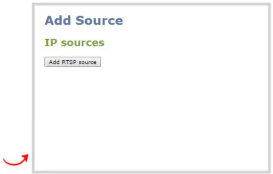
- Click Add RTSP source to open the source configuration page.


You can rename the source by clicking on the default source name at the top of the page ("RTSP 1" in the screenshot above). See Rename a source for more information.
- Under the Settings header, fill out the Source URL, Username and Password fields with information configured from your source RTSP device (see List of tested RTSP-based IP cameras for source URL syntax and credentials specific to IP cameras we at Epiphan have tested), and select either UDP or TCP from the Preferred transport dropdown menu.
Optionally, you can also fill out the "No signal" image settings, if desired. See Add a No Signal image to a source for more information.

See Stream content using HTTP or RTSP if using another Pearl-2 as an RTSP source.
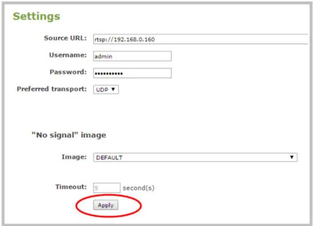

If using the RTSP link from another channel on your system (for an RTSP channel loopback), replace the IP address with localhost or 127.0.0.1 for best results. Ensure preferred transport is set to TCP.
- Click Apply to save your settings and connect your RTSP source.
Once your RTSP source is connected, you can view its basic video and audio signal information and packet loss statistics under the Status header at the top of the page. If there are any warnings or errors associated with your RTSP stream, they are also displayed here.

Alternatively, you can view stream connection information by clicking the check link under the Stream info header at the bottom of the page.

Create an RTSP loopback
If you want to use use multi-encoding and re-encode your Pearl-2 channel at another resolution or bitrate, it's easy to do with an RTSP loopback.
For example, to make channel 2 be a 720p version of your fully switched 1080p program on channel 1, you take the RTSP stream from you program channel (e.g. channel 1), and use it as both the video and audio source for channel 2.
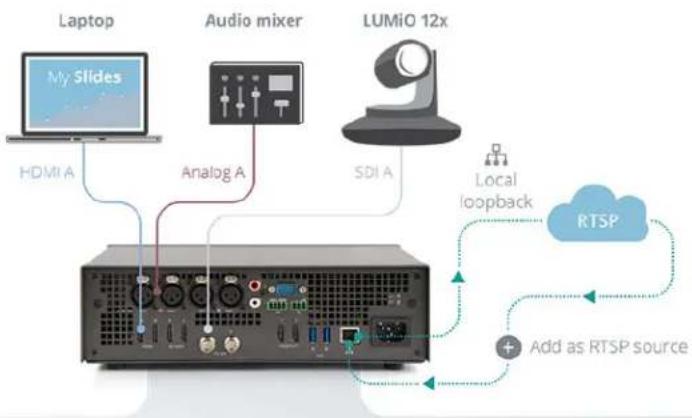
flowchart
graph TD
    A["Laptop"] -->|HDMI A| B["Audio mixer"]
    B -->|Analog A| C["LUMiO 12x"]
    C -->|SDI A| D["Local loopback"]
    D --> E["RTSP"]
    E --> F["Add as RTSP source"]
    style A fill:#f9f,stroke:#333
    style B fill:#ccf,stroke:#333
    style C fill:#cfc,stroke:#333
    style D fill:#fcc,stroke:#333
    style E fill:#cff,stroke:#333
    style F fill:#ffc,stroke:#333
Channel 1
Program Out for recording
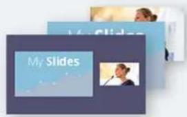
- Recording - 1080p, 8 Mbps
Video sources - HDMI A, SDI A
(1) Audio sources - Analog A
Channel 2
Program Out for streaming
Streaming - 720p, 1 Mbps
Video sources - RTSP source
Audio sources - RTSP source

When creating an RTSP loopback, use localhost or 127.0.0.1 as the IP address for your system. Also use TCP as the preferred transport method.
Read more about RTSP loopbacks, see Multi-Encoding.
You can also use a channel from another Pearl-2 as a source. To do this, add it as a regular RTSP source, with the correct full IP address.
List of tested RTSP-based IP cameras
The table below describes cameras tested to work with your Pearl-2 and includes helpful information such as URL syntax, default credentials and audio streaming capability specific to each camera.

Your Pearl-2 is compatible with all ethernet-based IP cameras and other RTSP sources. The cameras listed in the table below are a sample of common third-party cameras that have been tested to work with Pearl-2.
The URL syntax in the table below refers to the additional piece of text that needs to be included in the source URL to connect your IP camera to your Pearl-2. (See Connect an RTSP source to learn how to connect an RTSP source (like an IP camera) using the Admin panel.)
For example, to connect a Sony SRG300SE camera with an IP address of "192.168.0.160", your source URL needs to be entered as:
"rtsp://192.168.0.160/video1"
Or, if using a Q-See QCN8029Z camera, your source URL needs to be entered as:
"rtsp://192.168.0.160/"
Table 38 List of tested IP cameras
| Brand Model Image URL syntax Audio? | Default username and password | ||||
| Q-See QCN8029Z / No |  | admin admin | |||
| Sony SRG300SE |  deo1 Yes deo1 Yes | admin admin | |||
| Panasonic | AW-HE40HPK * |  | /MedialInput/h264/stream_1(To add a second URL, use:"/MedialInput/h264/stream_2") | Yes | admin 12345 |
| Axis | P1428-E |  | /axis-media/media.amp | No | root root |
| Brand Model Image URL syntax Audio? | Default username and password | ||||
| Axis M1034-W /axis-media/m |  Yes Yes | root admin | |||
Note that in our testing, the Panasonic AW-HE40 does not always seem to sync its time with Pearl-2.
List of fully supported Web cameras
Pearl-2 is expected to support any web camera or USB audio source (such as a USB microphone) on the market, and have full functionality regardless of the brand and model. The web cameras listed below are fully supported and tested. Web cameras not on the list are still likely to work, but if you experience difficulties with one of them, try one of these models.
Table 39 List of tested Web cameras
• Logitech HD Pro Webcam C920 (Max video mode: 1920x1080@30)
• Logitech C925e (Max video mode: 1920x1080@30)
• Microsoft LifeCam Studio (Max video mode: 1280x720@30)
• Microsoft LifeCam HD-3000 (Max video mode: 1280x720@30)
• IPEVO Ziggi-HD Plus

For the Ziggi-HD Plus web camera, enable the power line frequency setting in the web camera before connecting the camera to Pearl-2.

When you Configure a source, Pearl-2 the Default video mode is not necessarily achievable for that web camera. For instance, a camera might have a Default mode of 1080p but have a Maximum video mode of 720p. If no settings are changed, the camera simply outputs video at 720p.

Not all settings are used for all cameras. Any settings not used are greyed out in the menu and unavailable to change.
Connect an AV.io video grabber
You can connect an Epiphan AV.io frame grabber to a USB input port just the same as you would connect a web camera.
Pearl-2 treats the video source from the frame grabber just like any other video source.
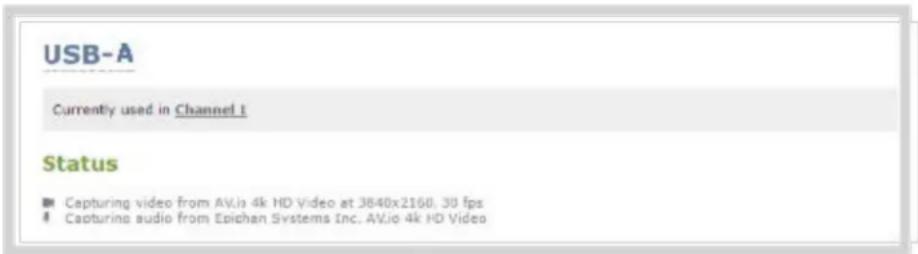
Use AV.io frame grabbers to connect extra HDMI, DVI, or SDI sources. Using AV.io HD, you can add up to two VGA sources to Pearl-2.
You can set up and operate frame grabbers using the same Configure a source
• AV.io HD: https://www.epiphan.com/userguides/avio-hd/Content/Home-AVioHD.htm
• AV.io SDI: https://www.epiphan.com/userguides/avio-sdi/Content/Home-AVioSDI.htm
• AV.io 4K: https://www.epiphan.com/userguides/avio-4k/Content/Home-AVio4K.htm
Preview a source
You can preview the images captured from your sources in the Admin panel. No extra configuration is needed.

You can also preview your sources using the Epiphan Live control interface. See Monitoring video and audio sources for more information.
To preview the captured stream/images in the Admin panel:
- Login to the Admin panel as admin. See Connect to the Admin panel.
- Ensure a source is connected to the input port, see Connect a source.
- From the Admin panel, click the source name from the Sources menu; the source configuration page opens.

- Scroll to the bottom of the source configuration page to see the preview.
Configure a source
Generally the captured stream doesn't require any additional configuration, but if needed, you can log into the Admin panel to make configuration changes.
To configure a source:
- Login to the Admin panel as admin. See Connect to the Admin panel.
- Ensure a source is connected to the input port, see Connect a source.
- From the Admin panel, scroll to the Sources menu option.

- Click the source link for your source (HDMI, SDI, USB video or RTSP); the source configuration page opens
- If desired, scroll to the bottom of the source configuration page to see the video Snapshot.
- Make note of the name of the source, or optionally, change the source name to reflect the data it is capturing. You'll need to know this name to add the source to a channel. See Create a simple channel.
- In most cases the video is ready to add to a channel and broadcast. If fine adjustments are required, refer to the table below to make minor configuration changes.
DVI and HDMI signals
The following options are available for DVI and HDMI signals via the HDMI port:

| Value Description | |
| Enable deinterlacing | Enable this feature to convert an interlaced source signal to a non-interlaced signal. |
| Enable 4K downscaling ^4K | Selecting this option means that your 4K UHDsource will be automatically downscaled to 1080p using Pearl-2's hardware. |
| Image | This menu allows you to choose a custom no-signal image for the channel. The drop-down list gives you the option to choose the default image or any image you have uploaded through the Add a No Signal image to a source |
| Timeout | The timeout represents the number of seconds after losing the signal that the n signal is displayed. You may change this number to adjust how soon you wish th no-signal image to appear after the signal disappears. |
^1 Requires 4K feature add on
SDI signals
The following options are available for signals via the SDI port.
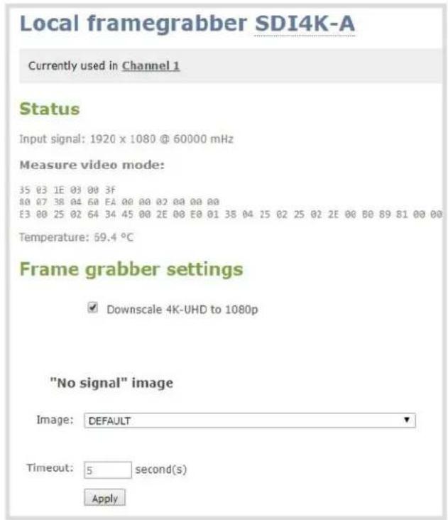
| Value Description | |
| Image | This menu allows you to choose a custom no-signal image for the channel. The drop-down list gives you the option to choose the default image or any image you have uploaded through the Add a No Signal image to a source |
| Timeout | The timeout represents the number of seconds after losing the signal that the n signal is displayed. You may change this number to adjust how soon you wish th no-signal image to appear after the signal disappears. |
USB signals
The following options are all potentially available for signals via the USB port. However, some apply only to certain types or brands of camera, and not all options are available or needed for all cameras.
USB-A
The source is not used in channels
Status
No USB video detected No USB audio detected
Settings
Video
Capture mode: 1920x1080 30 fps ▼
Brightness: 50 from 0 to 100
Contrast: 50 from 0 to 100
Vertical shift: 0 from -64 to 64
Horizontal shift: 0 from -64 to 64
Saturation: 0 from 0 to 100
Sharpness: 50 from 0 to 100
Power line frequency: 60 Hz
"No signal" image
Image: DEFAULT ▼
Timeout: 5 second(s)
Audio
Input gain: 70%
Audio delay: 0 from -300 to 300 ms
Apply
| Value Description | |
| Capture mode | This feature is useful for simultaneously dictating the resolution and fps at which the camera is captured. The drop down list of available resolutions and frame rates changes depending on the attributes of the connected device. |
| Brightness | The brightness of the video can be adjusted by entering a numerical value from 0 to 100. Estimate values and view the result in the preview area until desired result is achieved. |
| Contrast | The contrast of the video can be adjusted by entering a numerical value from 0 to 100. Estimate values and view the result in the preview area until desired result is achieved. |
| Vertical shift | The vertical positioning of the video can be adjusted by entering a numerical value from -64 to 64. Estimate values and view the result in the preview area until desired result is achieved. |
| Horizontal shift | The horizontal positioning of the video can be adjusted by entering a numerical value from -64 to 64. Estimate values and view the result in the preview area until desired result is achieved. |
| Saturation | The saturation of the video can be adjusted by entering a numerical value from 0 to 100. Estimate values and view the result in the preview area until desired result is achieved. |
| Sharpness | The sharpness of the video can be adjusted by entering a numerical value from 0 to 100. Estimate values and view the result in the preview area until desired result is achieved. |
| Powerline frequency | The powerline frequency of the video can be adjusted by selecting the desired output from a drop-down list of frequencies available to your source. |
| Image | This menu allows you to choose a custom no-signal image for the channel. The drop-down list gives you the option to choose the default image or any image you have uploaded through the Add a No Signal image to a source |
| Timeout | The timeout represents the number of seconds after losing the signal that the no-signal is displayed. You may change this number to adjust how soon you wish the no-signal image to appear after the signal disappears. |
| Audio input gain | You can add audio gain to your source from this page by selecting the % gain from the drop-down list. Estimate values and check the result in the preview area until desired result is achieved. |
| Audio delay | If your audio is not synchronized with your video, it can be adjusted from -300 to 300 ms. Estimate values and check the result in the preview area until desired result is achieved. |
RTSP sources
RTSP sources are configured for connection to your Pearl-2 using the Source URL, Username and Password specific to your selected RTSP source. (See Connect an RTSP source for more information).
RTSP sources can be further configured with a Preferred transport protocol (either UDP or TCP) and a custom "No signal" image. (See Add a No Signal image to a source).
Add a No Signal image to a source
By default the system displays a No Signal image when there is no video signal coming in to a source. You can customize this image to display a different message to your viewers. For example if a viewer logs in early, or if you are experiencing delays you could indicate the start time (or expected resolution time) using the no signal image.
Before you can specify a custom no signal image for a source, you must upload it following the procedure To upload an image.
To set the no signal image for a source:
- Login to the Admin panel as admin. See Connect to the Admin panel.
- Follow the instructions above (To upload a logo to a channel) to upload an image via the Branding Content page.
- From the Admin panel, select your desired source under the Source header; the source configuration page opens.
- Select a "No signal" image. This image displays in the channel when the source's signal is not detected. (If your uploaded image does not appear in the list, ensure it doesn't exceed the maximum image size of either 1080 or 2160 ^4K . Image file formats supported are PNG and JPEG.)
Alternatively, to select an image you can simply drag and drop your chosen picture file to the blank space below the Image field.
-
In the Timeout field, enter the number of seconds before the "No signal" image is displayed. If no manual value is entered, the default time to display is 5 seconds.
-
Click Apply.
-
Test that the No Signal image is correctly applied by disconnecting your source and previewing the channel(s) containing said source. See Preview a channel for more information.
Rename a source
Source names are used when adding sources to channels, therefore it is important that you know the name of the source you wish to use. If a channel has only one source, the channel name will by default be the same as its source name and will update automatically when the source name changes.
Sometimes it's helpful to configure the source name to match the data it's capturing so it's clear what the channel is capturing too. Alternately you can change the channel's name. See Rename a channel.
To change a source name:
-
Login to the Admin panel as admin. See Connect to the Admin panel.
-
From the Admin panel, scroll to the Sources menu option.

- Click the desired source link; the source configuration page opens.
- Click the source name at the top of the page; the name turns red.
- Highlight and delete the existing source name.
- Type a new source name.
- Press Enter (on your keyboard) to save the new name.

You must press Enter to save the new name. The Apply button will not save the source name change.
Adjust audio gain (analog audio) and delay
The audio ports on the portable Pearl-2 model are calibrated for +4.0 dBu XLR or -10.0 dBV RCA, and provide moderate to significant signal headroom.
The audio page also allows you to set audio delay. By default, it is set to have 0 ms of delay, but you can change that number to anywhere between -300 and +300 ms of offset from the original synchronization.

Microphones typically have very low audio signals (less than -30 dBu) and are not supported directly as inputs to Pearl-2. Use an audio mixing board to amplify microphones to appropriate levels.
If your audio signals need further adjustment, try checking audio levels through the audio monitor or VU meter and adjusting as needed. As a rule of thumb, each 10 dB of increased gain doubles perceived loudness of the audio signal.
To adjust audio settings for gain and delay:
- Ensure an audio input source is connected to an analog audio input port.
- Login to the Admin panel as admin. See Connect to the Admin panel.
- From the Admin panel, scroll the Sources section.
- Select an audio source; the audio configuration page opens.
Audio Analog-A Audio
The source is not used in channels
Input gain: +0 dB ▼
Audio delay: 0 from -300 to 300 ms
Apply

bar
| Category | Value (dB) | |---|---| | L | -60 | | R | -50 | | | -40 | | | -30 | | | -18 | | | -9 | | | 0 |
Both balanced and unbalanced signals are supported - adjust the gain as needed for unbalanced signals.

"Passive" microphones requiring phantom power are not supported. Supported microphones require their own external power source, such as a battery.
- To adjust the relative volume of the audio, click the Input Gain drop-down menu. Select your required input gain (which, in general terms, increases the perceived volume of your signal). Fine tune as needed for your audio levels.

Adjusting the Input Gain adjusts audio levels in the recorded and streamed output as well as the headphone monitor and through the video output ports (if displaying this channel).
- You may also make adjustments to Audio delay by clicking on the text box. There, you can type any number between 300 and -300. After clicking Apply, the timing of the audio is adjusted by that many milliseconds. Entering a positive value adjusts the audio by shifting the audio to start later in the video, while entering a negative value adjusts the audio to start earlier. Fine tune as needed to ensure that it's synchronized with the video.

Pearl-2 does not cause audio delay, and has near-zero latency in capturing. However, many different external factors can cause audio to become de-synchronized, notably the length of the audio cables or the configuration of the equipment used. The audio delay features can help adjust the audio coming from external sources and ensure that your sources are captured and recorded with proper synchronicity.
Audio Analog-A Audio
The source is not used in channels
Input gain: +0 dB ▼
Audio delay: 0 from -300 to 300 ms
Apply

- Click Apply.
Confirm audio levels
Pearl-2 has several audio VU meters that you can use to check audio levels:
• Using the touchscreen
- On the audio source configuration page using the Admin panel
• Using Epiphan Live (see Monitoring video and audio sources)
The touch screen shows an audio meter for each channel in both the grid and individual channel views. The audio meter can also be added to the video output ports. See Disable or enable the audio on the video output port.
If you can't see the audio meter on the touch screen, tap the screen once to turn on decorations.
Channels that have stereo audio display two bars. The top bar is the left audio channel and the bottom bar is the right audio channel.
| VU Meter (mono audio) |  | |
| VU Meter (stereo audio) |  |  |
Table 40 Audio VU meter levels
| Color Decibel range | |
| Red 0 to -9 dBFS | |
| Yellow -9 to -18 dBFS | |
| Green -18 dBFS and lower |
To view the audio signal on the touch screen:
- If needed, touch the screen once to turn it on.
- Select either the grid view or the individual channel view. The VU meter appears along the bottom of the channel preview.
To view the audio VU meter from the audio source configuration page using the Admin panel:
- Scroll to the Sources section and select an audio source. The audio source configuration page appears.
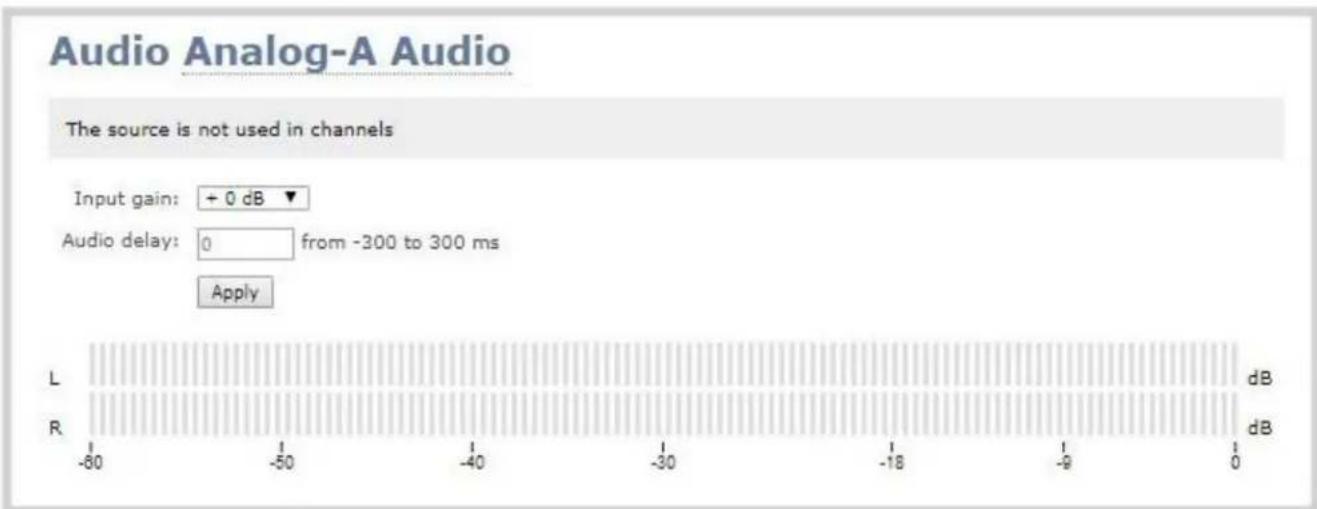
Troubleshoot capture
In addition to fine tuning channel settings such as frame rate, resolution and bit rate to ensure optimal use of resources while streaming a quality video, there may be circumstance when you must fine tune the video input source.

It's good practice to backup your configuration settings so that you can revert back to a good configuration if the changes you made are not desirable. See Configuration presets.
The following topics are covered in this section:
- Remove black bars (matte) from the video
• Force the capture card to use a specific EDID - Unstretch the output video
- Remove the combing effect on images
Remove black bars (matte) from the video
By default, for channels with only one layout and only one source, Pearl-2 makes sure that the aspect ratio of input signals is preserved when the output is streamed. If an input video signal doesn't match the encoded frame aspect ratio, bars are added to the sides or top and bottom of the encoded stream when the output is streamed and recorded. The color of the bars (matte) is defined by the Background color selected on the Channel sources page. See Create a custom channel.
For example:
- Input signal resolution is 720 × 480 (a 3:2 aspect ratio)
- encoded resolution is 640 × 480 (a 4:3 aspect ratio that is narrower than the input resolution)
Borders are added to the top and bottom of the image to preserve the wider ratio of the input.
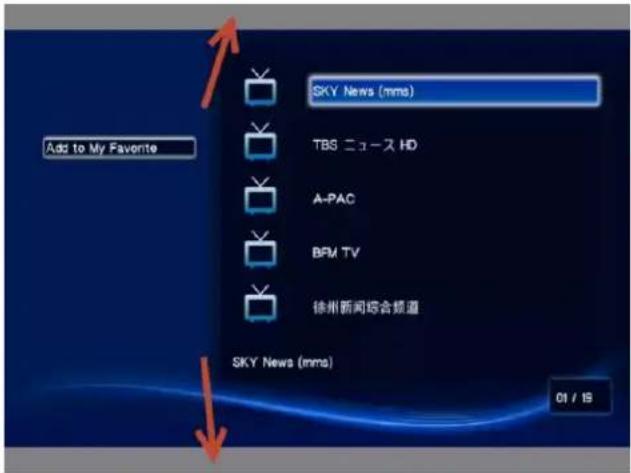
- Input signal resolution is 720×480 (a 3:2 aspect ratio)
- encoded resolution is 1280 × 800 (a 16:10 aspect ratio that is wider than the input resolution)
Borders are added to the left and right of the image to preserve the narrower ratio of the input.
If you are seeing bars on your image but would rather have the image fill the whole screen you have to options:
- Change the output frame size to match the aspect ratio of the input.
- Stretch the image to fit the output frame size aspect ratio.
These two options are described below.
Match the output frame size to the aspect ratio of the source signal

The frame size is matched only for layouts that have only one source. Note that if you have layouts with different frame sizes, switching them while live streaming will cause an interruption and restart of the stream. The same thing happens if you change the resolution of your source while streaming.
To change the output frame size on channels to match the aspect ratio of the source:
-
Connect to the Admin panel using your preferred connection mechanism. See Connect to the Admin panel.
-
Login as admin.
- Select a channel; the menu expands.
- Click Sources; the Sources page opens.
- Find the name of the media source used for the channel.
- Click this source under the Sources menu.

- Make note of the input signal resolution.
- Click the channel's Encoding; the Encoding page opens.
- Scroll to the frame size parameter.
- The simplest option is to select Use current signal resolution as frame size and click Apply. You can alternatively select it briefly to note the current video signal resolution, then deselect it and follow the steps below.

- Look for the source aspect ratio in the list of aspect ratios provided.

a. If the source resolution is on the list, choose another resolution on the same line (i.e. with the same aspect ratio).
b. If the source resolution is not on the list, use a calculator to get a factor of the source resolution and enter it in the Frame size fields.
- Click Apply.
Stretch the image
To remove the matte (black bars) by stretching the image to fit your output frame size:
- Login to the Admin panel as admin. See Connect to the Admin panel.
- Select a channel; the channel menu expands.
- Click Sources; the Sources page opens.
- Click the row for your layout; the layout appears in the layout editor.
- Select the gear for your Item with your video source; the Source Settings box appears.
- Deselect Keep aspect ratio when scaling in the Source Settings box.
- Click and drag the source in the layout editor to stretch as desired to fill the frame.
- Click Save.
Force the capture card to use a specific EDID
Extended display identification data (EDID) is data provided by a video display device (usually a monitor) to describe its capabilities to a video source (usually a graphics or video output card in a PC or another device). The video source uses the EDID to determine the capabilities of the monitor in regards to the resolutions, color depth and other settings that the monitor can support.

EDID is crucial for DVI sources.
Like monitors, each video capture card in Pearl-2 contains an EDID. When you connect a DVI video source (such as a laptop or video camera), this source sees Pearl-2's capture card as a monitor and uses its EDID to negotiate which video signal to send.
Generally capture card's DVI input correctly emulates a monitor that supports your video source. However sometimes, particularly if your source uses a custom set of display properties, you need to help Pearl-2's by uploading a custom EDID to force the capture card to report that it emulates a resolution, color depth, etc needed by your laptop, camera or other video source.
Upload a new EDID
In most circumstances the factory installed default EDID, is sufficient. However, there may be some cases where a video source uses resolutions that you do not want to use. In that case you can choose an EDID that forces Pearl-2's capture card to use a specific set of attributes.
The uploaded EDID is permanently installed on your system and this capture card (a "Source" in the Admin panel) will always share the uploaded EDID with the connected video input source.

EDID changes are permanent until you replace them with another EDID or specifically choose to restore the facotry EDID for a given source. Not even a system-level factory reset removes the configured EDIDs.
- To download a new EDID file, go to the Epiphan support web page. The support page opens.
- Select the support page for Pearl-2.
- Scroll to the EDID section.
- Click on an EDID from the list. The file is saved to your downloads folder on your hard drive.
- Connect to the Admin panel using your preferred connection mechanism. See Connect to the Admin panel.
- Login as admin.
- From the Admin panel, Scroll to the Sources section.
- Click the name of the HDMI capture card (source) for which you want to upload an EDID; the Source Configuration page opens.
- Scroll to the EDID upload section.

- Click Choose File; a file browser opens.
- Browse to the location where the custom EDID file was saved and select the file.
- Click open; the EDID filename is displayed on the screen.
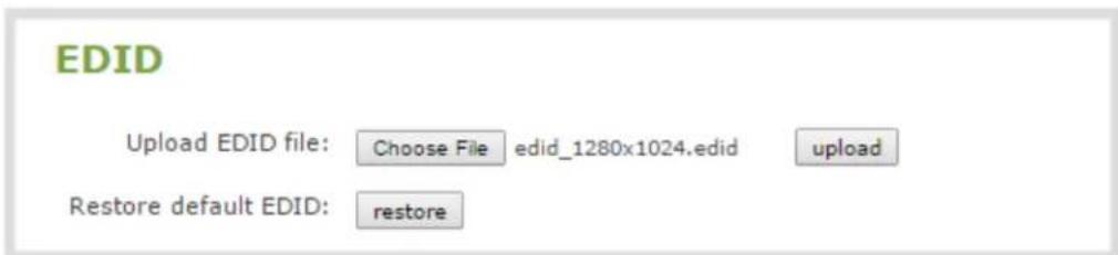
- Click upload, the EDID upload begins; the screen shows a progress in indicator.
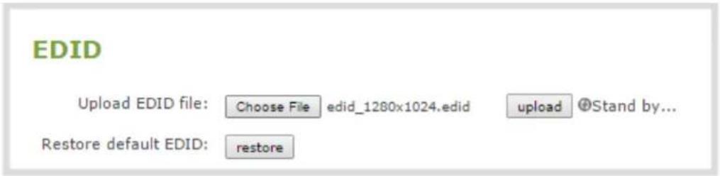
- When the upload is complete the page changes to reflect success or failure.
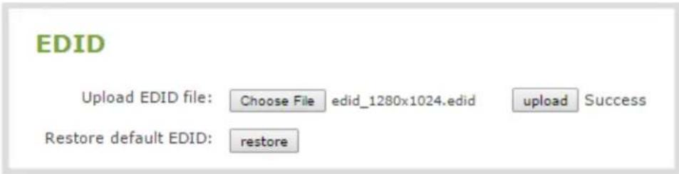
Restore factory default EDID
When you have finished with a custom EDID, you can restore the capture card (in the Sources list) to the default EDID. Currently there is no way to tell if your capture card is using a custom EDID. If you are unsure, restoring to factory default is the best approach.
To restore the default EDID:.
- Login to the Admin panel as admin. See Connect to the Admin panel.
- From the Admin panel, scroll to the Sources section.
- Click the capture card (source) for which you wish to restore the EDID; the source configuration page opens.
- Scroll to the EDID section.
- Click the restore button.

- The screen updates with a status indicator.
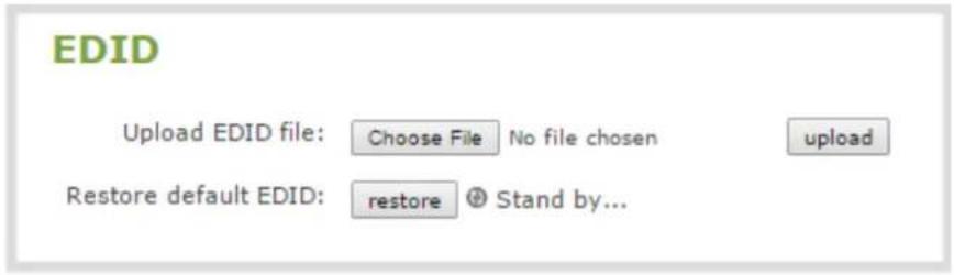
- When the EDID restoration is complete, the page updates to reflect the action is completed.

Unstretch the output video
By default, Pearl-2 makes sure that the aspect ratio of input signals is preserved when the output is streamed. If this default was overridden the image is stretched to match the output frame size. The effect may be subtle and may not be problematic for you, but if you want to resolve this it is very simple to do.
To preserve the source aspect ratio:
- Connect to the Admin panel using your preferred connection mechanism. See Connect to the Admin panel.
- Login as admin.
- Click on your channel, then select Sources; the Sources page opens.
- At the top of the page, click the row for the layout you want to edit, then click on the relevant layout item; the Source settings box appears.
- From the Source settings box, make sure Keep aspect ratio when scaling is selected.

- Scroll to the bottom of the page and click Save.

Unstretching the image causes a matte (black bars) to appear on the sides or top and bottom of the output. To remove these see Remove black bars (matte) from the video.
Remove the combing effect on images
When frames are interlaced, artifacts from one frame may appear on the next frame. This occurs when a fast motion video is interlaced. Since each frame is captured from a different point in time, the action captured in one frame is carried over to the next frame. The result is a blurred image and horizontal lines running across the video.
To convert an interlaced source signal to a non-interlaced signal.
- Login to the Admin panel as admin. See Connect to the Admin panel.
- From the Admin panel, scroll to the Sources menu option.

- Click on the desired video source; the source configuration page opens.
- Enable the Enable deinterlace setting.
- Click Apply. View the output in the Snapshot preview below.
PART 3: Stream
Streaming provides powerful and flexible approaches to delivering to your users. Offering an easy to use interface, users can stream video using multiple formats to multiple users and devices such as web browsers, media players, set-top-boxes, Smart TVs and Content Distribution Networks.
The system is flexible and supports standard codecs used by most sharing destinations and media players.
This section discusses the following topics related to publishing your content:
• What is streaming?
- Stream to viewers
- Stream to a server
• Stream to a media player or smart TV
• Samples of stream settings
What is streaming?
After you have configured your media and channels, decided on the content and layout of your broadcast, it's time to share your stream.
Pearl-2 provides a number of options for streaming. Choose from methods for unicast, multicast, CDN, SAP, UPnP and more.
When streaming to a server, you can use Pearl-2's touch screen (see Specify channels for One Touch streaming) or Admin panel to control when streaming starts and stops.
The following sections provide a description of the available streaming options, insight into why you would choose each option, and procedures to stream your content using each option.
- Choose a streaming option
- Supported streaming formats
Streams for viewers:
Stream to viewers
- Disable (and enable) streams for viewers
o. Restrict access to streams for viewers
Stream content using HTTP or RTSP
- Configure HTTP and RTSP streaming ports
Stream content using HLS (HTTP Live Streaming)
Stream content using UPnP
Stream to a server:
Stream to a server
Stream to a CDN
Stream content using multicast
Stream to a media player:
Stream to a media player or smart TV
Choose a streaming option
Each method of streaming media has strengths and weaknesses depending on your audience location, hardware resources and bandwidth. To help you decide how to publish your content, you must first identify the number of viewers and how viewers will access your content. Are you streaming live video, or recorded
video. Do you need to stream the content to one client (peer-to-peer), deliver a single stream to multiple clients (multicast), or provide web-based streaming where multiple clients can access the broadcast (Content Distribution Network).
Your Pearl-2 can stream to individual viewers through HTTP, HTTP Live Streaming, UPnP and RTSP and can also simultaneously stream to a server such as a multicast server or CDN.
Supported streaming formats
When you set up your channel the system generates and displays a list of available video formats and standards specific to the selected audio and video codecs used by your channel.
To view the video formats and standards specific to your selected codec:
- Login to the Admin panel as admin. See Connect to the Admin panel.
- From the Admin panel, click a Channel; the menu expands.
- Click Status; the following page opens displaying the stream protocol that is supported based on the selected codecs.
Stream info
Live broadcast: http://192.168.0.183/preview.cgi?channel=1
Video: H.264 1920x1080@30, 6.47 Mbps
Actual framerate: 30
Audio: AAC 44kHz stereo 320 kbps
Total: 6.79 Mbps
RTSP stream rtsp://192.168.0.183:554/stream.sdp
MPEG-TS stream http://192.168.0.183:8000/stream.ts
Flash stream http://192.168.0.183:8000/stream.flv
Copy, paste and share files and addresses with viewers
Stream to viewers
Streaming to viewers allows people to connect directly to your Pearl-2 via their web browser or media player to view the live stream.
You can configure whether or not streaming is enabled for viewers. See Disable (and enable) streams for viewers.
| Publishing Options Use this option to... | |
| HTTP | Quickly stream content to viewers simultaneously. No set up is required. Pearl-2 is ready to stream content as soon as it is has power and a configured channel. No other settings are required. Your audience need only access the URL of the broadcast and they are instantly connected. This viewing method is ideal for a small number of viewers. For each viewer, you are using the full stream bandwidth and a small amount of system overhead on the Pearl-2. For more information about using a HTTP streaming, refer to Stream content using HTTP or RTSP. |
| RTSP | Quickly stream content to viewers. No set up is required. Pearl-2 is ready to stream content as soon as it has power and a configured channel. No other settings are required. Your audience need only copy and paste the URL of the stream into a media player. For more information about using a RTSP and HTTP streaming, refer to Stream content using HTTP or RTSP. |
| HTTP Live Streaming (HLS) | Stream live over the standard HTTP port 80, making it possible to cross firewalls and proxies that are normally accessible to other HTTP traffic and facilitates content delivery to CDNs. See Stream content using HLS (HTTP Live Streaming).There is approximately a 30 second delay when streaming using HLS. |

To stream video outside of your LAN, configure port forwarding on your router. Work with your Network Administrator on this task. Network configuration is beyond the scope of this guide.
Stream content using HTTP or RTSP
The quickest and simplest way to deliver your content is to send the broadcast's URL to your viewers. You can provide separate URLs for each channel being streamed.
The format of the URL provided to you by the Admin panel depends on the method you used to access the system, either through network discovery using the serial number or IP address.

The system must be accessible on the viewer's LAN for the viewer to use access by serial discovery.

If your system is behind a firewall and you wish to share with remote viewers, you will need to set up port forwarding on your network. See your IT administrator.
Table 41 URL options
| Access Method URL Format | |
| serial discovery | http://.local/preview.cgi?channel=rtsp://.local:/stream.sdpWhere serial is the serial number of the system and channel number is the provided from the GUI (see below). |
| IP address | http:///preview.cgi?channel=2rtsp://:/stream.sdpWhere the IP address is the IP address of the system and the port and channel number informationis provided on the channel's status page. |
To retrieve the stream URL for your viewers:
- Login to the Admin panel as admin. See Connect to the Admin panel.
- From the Admin panel, click a Channel; the menu expands.
- Click Status; the following page opens displaying the stream protocol that is supported based on the selected codecs.
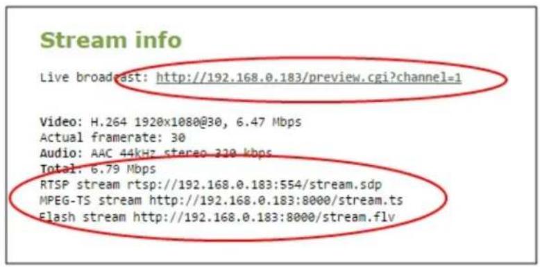
- Jot down the either the Live Broadcast, RTSP stream or other web streaming address. This is the address you can send to viewers or to create a link to your broadcast.

If getting the RTSP link for your Pearl-2 channel to use as an RTSP loopback, replace the IP address (e.g. 192.168.0.183 from the example above) with localhost or the address 127.0.0.1 - this gives better results.

Users must install Bonjour Print Services on their Windows or Mac computer to access the live Preview using the serial number.

If you're seeing URLs with serial numbers instead of IP addresses and want to change this, log into the Admin panel by IP address (instead of by Serial number/Bonjour Print Services) to see URLs with the IP address. (See Connect to the Admin panel.)
Configure HTTP and RTSP streaming ports
For RTSP streaming directly to users on your LAN the only information required to view the broadcast is the URL and the port number used to stream the broadcast.
Port numbers are also used for HTTP streaming methods such as FLV and MPEG-TS. By default, each channel has a unique HTTP and RTSP port number. If needed, you can modify these port numbers. Be sure to always use unique numbers for each channel.
To set the HTTP and RTSP streaming ports for streaming to viewers on the same network, follow the steps below.
-
Login to the Admin panel as admin. See Connect to the Admin panel.
-
From the Admin panel, click a Channel; the menu expands.
- Click Streaming; the channel's Streaming page opens.
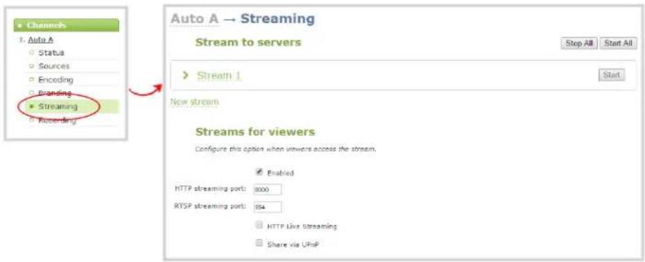
- Set the HTTP Streaming port to specify the port used to stream the HTTP broadcast. This value along with the URL is used by viewers to access the FLV and MPEG-TS streams.

The port number must be higher than 500 for HTTP. In the case of RTSP streaming this value is ignored.
- Set the RTSP Streaming port to specify which port to use when you are streaming live video via RTSP. This value along with the URL is used by viewers to access the broadcast. The default for channel one is 554.
- Click Apply.
Stream content using HLS (HTTP Live Streaming)
Stream live over the standard HTTP port 80, making it possible to cross firewalls and proxies that are normally accessible to other HTTP traffic.

HLS is supported with the H.264 codec and MP3 or AAC audio encoding. When streaming using HLS there is approximately a 30 second delay.
- Login to the Admin panel as admin. See Connect to the Admin panel.
- From the Admin panel, select the channel containing video you want to stream; the menu expands.
- Click Streaming; the channel's Streaming configuration page opens.
- Enable HTTP Live Streaming by selecting the HTTP Live Streaming checkbox.
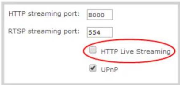
-
Click Apply.
-
Click Status for the channel. The status page opens.

- Provide the HLS stream link to your viewers.
Send stream URLs to viewers
For participants to log in and view a stream, you must provide a stream URL. The URL that you send depends on the device the participant uses to view the stream. You can provide separate URLs for the stream coming from each channel, or one URL that includes all the streams for the channel.
- Login to the Admin panel as admin. See Connect to the Admin panel.
- From the Admin panel, click the channel that you want to view; the menu expands.
- Click Status; the Status page opens displaying the stream protocols supported based on the selected codecs. For more information on compatibility between codec and file formats, see Supported streaming formats.
MPEG-TS: Used in broadcast systems such as DVB, ATSC and IPTV. It is supported by media players such as MPIayer, VLC and KMPIayer.
RTSP: Supported by most media players including QuickTime, MPlayer and VLC. Supports H.264 and MPEG4 standards and analog audio from an external source.
Stream info
Live broadcast: http://192.168.0.183/preview.cgi?channel=1
Video: H.264 1920x1080@30, 6.47 Mbps
Actual framerate: 30
Audio: AAC 44kHz stereo 320 kbps
Total: 6.79 Mbps
RTSP stream rtsp://192.168.0.183:554/stream.sdp
MPEG-TS stream http://192.168.0.183:8000/stream.ts
Flash stream http://192.168.0.183:8000/stream.flv
ASF: Supported on Windows Media Player. Additional codecs may be needed to view ASF streams. Supports H.264 and MPEG4 standards. Supports analog audio from an external source.
FLV: Supported on most web browsers and media players. Supports the H.264 standard and analog audio from an external source.
- Copy the URL and provide to viewers.
Viewers may now view the stream using a digital media player or browser. See Viewing with a web browser and Viewing with a media player (RTSP).
View the Flash stream
There are two methods to view the retrieve the flash stream URL:
• Live broadcast link on the channel's status page.
• Info page from the configuration menu
View your broadcast using the View link on the Info menu
-
Login to the Admin panel as admin or operator. See Connect to the Admin panel.
-
From the Admin panel, click Info menu option; the info window opens with a list of all configured channels.
| # | Channel name | Status | Video source | Audio source | Stream | Bitrate | Actual bitrate | Frame size | FPS / Actual FPS | Port | |
| 1 | Auto A | ok | SDI-A | SDI-A Audio | H.264+aac | 5000 kbps | 578 kbps | 1920x1080 | 30 / 29.9 | 8000 | View |
| 2 | Auto B | ok | SDI-B | SDI-B Audio | H.264+aac | 5000 kbps | 421 kbps | 1920x1080 | 30 / 30.0 | 8001 | View |
| Overall system load: 32% | |||||||||||
| Pearl-2 B7E5C813 info | |||||||||||
| Firmware | |||||||||||
| Version: 4.0.0cRevision: 35719_1771Date: 2016-08-22 | |||||||||||
| Hardware | |||||||||||
| CPU board: SKYBAR (Default string) | |||||||||||
| Channels | |||||||||||
| # | Channel name | Status | Video source | Audio source | Stream | Bitrate | Actual bitrate | Frame size | FPS / Actual FPS | Port | |
| 1 | HDMI-A | ok | HDMI-A | HDMI-A Audio | H.264+PCM | auto | 1621 kbps | 1920x1080 | 30 / 30.0 | 8000 | View |
| 2 | HDMI-B | ok | HDMI-B | HDMI-B Audio | H.264+PCM | auto | 1615 kbps | 1920x1080 | 30 / 30.0 | 8001 | View |
| 3 | HDMI4K-A | ok | HDMI4K-A | HDMI4K-A Audio | H.264+PCM | auto | 1617 kbps | 1920x1080 | 30 / 30.0 | 8002 | View |
| 4 | HDMI4K-B | no signal | HDMI4K-B | HDMI4K-B Audio | H.264+PCM | auto | 3578 kbps | 1920x1080 | 30 / 30.0 | 8003 | View |
| 5 | SDI4K-A | no signal | SDI4K-A | SDI4K-A Audio | H.264+PCM | auto | 1599 kbps | 1920x1080 | 30 / 24.8 | 8004 | View |
| 6 | SDI4K-B | no signal | SDI4K-B | SDI4K-B Audio | H.264+PCM | auto | 1642 kbps | 1920x1080 | 30 / 30.0 | 8005 | View |
| Overall system load: 20% | |||||||||||
- Click on the channel you want to preview. A page opens displaying the live broadcast and broadcast URL.
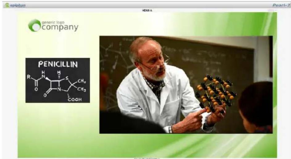
- Copy the URL and provide to viewers.
View your broadcast using the Live broadcast link on the Status page
- Login to the Admin panel as admin or operator. See Connect to the Admin panel.
- From the Admin panel, click the channel that you want to view; the menu expands.
- Click Status; the status page opens displaying the live broadcast and stream URL.
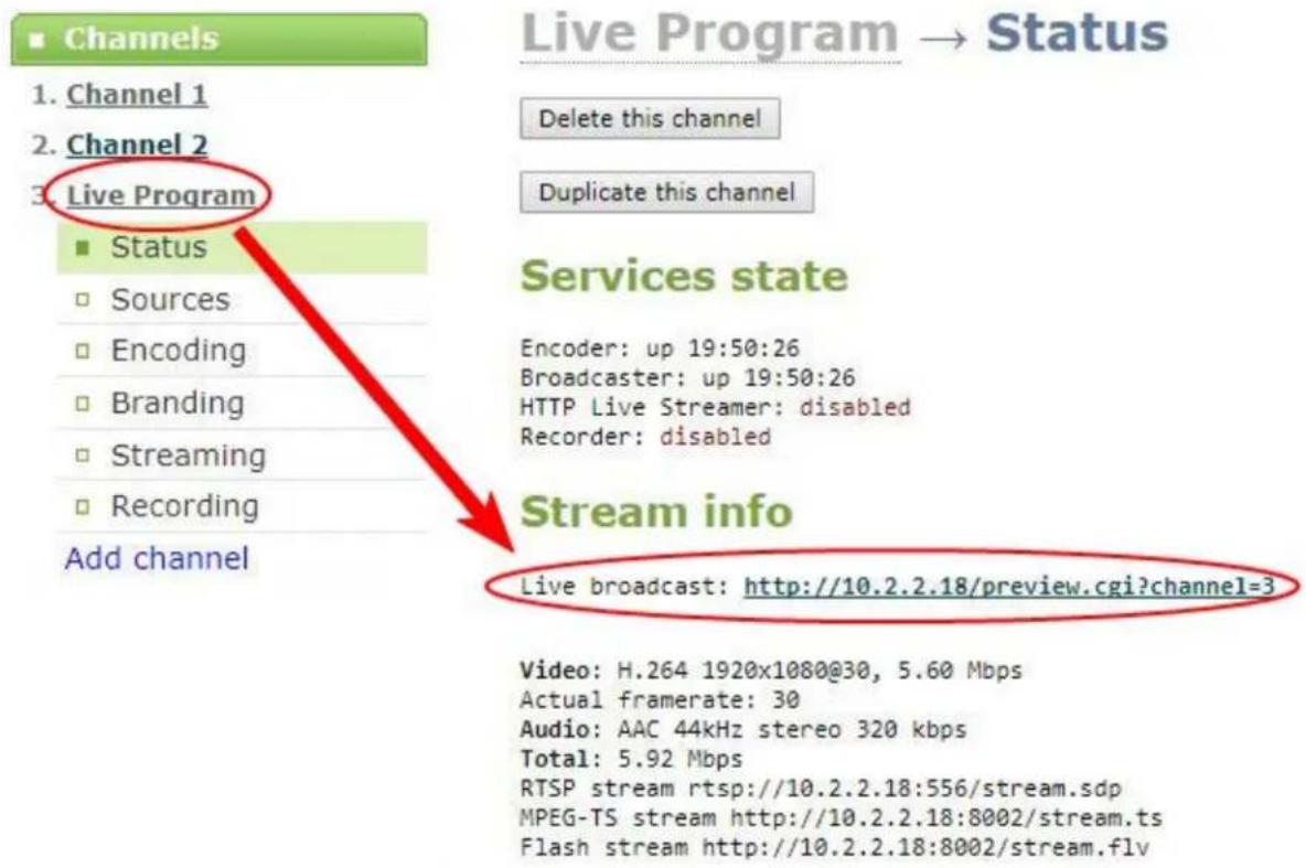
- When HTTP live streaming for the channel is enabled the status page also shows the HTTP Live Streaming link. See, Stream content using HLS (HTTP Live Streaming).

When HLS is enabled and with no viewer password set, viewers can access the stream using a tablet or smart phone device. If the viewer passwords is set, HLS connections are not possible.
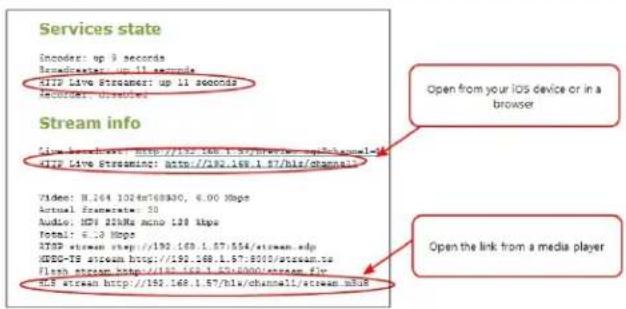
- Click on the Live broadcast or HTTP Live Stream link, if it configured. The window opens displaying the live broadcast and broadcast URL.

Previewing the broadcast with FLV player results in moderate buffering delay (15-30 seconds).
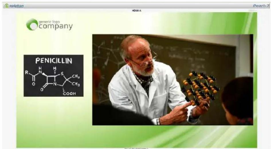
- Copy the URL and provide to viewers.
Viewing with a web browser
If a viewer password is configured, provide participants with the password to log in, along with the IP address or the URL to be used by the participant's browser.

If your channel is configured with 48 kHz audio, flash streaming that is used for browser viewing may not work. In this case, we recommend you view the channel with a media player instead. (See below.)
- Open a web browser.
- Enter the IP address of the broadcast stream, refer to the example below. To locate the IP address for the broadcast, refer to Send stream URLs to viewers.
If the IP address of the broadcast is 172.20.1.33, then browse to: http://172.20.1.33/preview.cgi?channel=
- Enter the user name and password at the prompt:
User Name: viewer
Password: (enter the viewer password)
- Press Enter. The stream is played in the browser window.
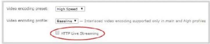
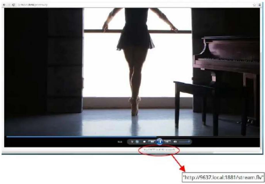
Viewing with a media player (RTSP)
If a viewer password is configured, provide participants with the password to log in, along with the IP address or the URL to be copied to the media player. For example purposes the following procedure describes the steps using a VLC media player.
- Launch a media player.
- Click the Media tab, a drop-down menu opens.
-
Choose Open Network Stream; a dialog box opens.
-
Enter the stream URL (using either the IP address or the network discovery serial number method).
rtsp://49E7B8E4.local:554/stream.sdp
![LC media player Media Playback Audio Video Customize Tools Views Help Open File... Ctrl+O Open Migration Files... Ctrl+Shift+O Open Folders... Ctrl+F Open Disc... Ctrl+D Open Network Stream... Ctrl+N Open Caption Device... Ctrl+C Open Location from folded Ctrl+V Open RecentMedia Save Playlist to File... Ctrl+V Connect / Save... Ctrl+B Open Media File Disc Network Capture Device Network Protocol [See Enter a network URL] http://www.roadstream.org/10.1234/ http://www.roadstream.org/10.1234/ http://www.roadstream.org/10.1234/ Show more options Play Cancel http://W6771local554/stream.csg - VLC media Player Media Playback Audio Video Subtitle Tools View Help](/content/2026/06/1365921/images/6db3fb89072d10479ec28d6346148397ad78222791a1d41f397bb4bb60bdc498.jpg)
- Press Play; the stream is played in the media player window.
Disable (and enable) streams for viewers
When you create a channel, it's available by default for viewing by stream viewers who have the stream URL. You can choose to disable streaming to viewers through the channel's streaming configuration.

Disabling streams for viewers disables all viewer formats including HTTP, RTSP, HLS and UPnP.
To disable (or enable) streams for viewers:
- Login to the Admin panel as admin. See Connect to the Admin panel.
- From the Admin panel, click Streaming for the desired channel; the streaming page opens.
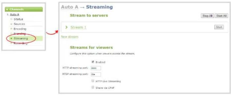
- Uncheck Enabled to disable streaming to viewers (or check to enable).
- Click Apply at the bottom of the page.
Restrict access to streams for viewers
Pearl-2 can restrict access to all viewer streams using global viewer passwords and IP allow/deny lists. See Set or change user passwords and Restrict viewers by IP address.

If LDAP is configured for viewer authentication, the viewer must pass global autentication using LDAP credentials (or the viewer global password, if there is one) and must meet the local channel settings (come from an allowed IP address). See Configure LDAP for more information on LDAP configuration.
To restrict viewers for a channel:
- Login to the Admin panel as admin. See Connect to the Admin panel.
- From the Admin panel, click Streaming for the desired channel; the streaming page opens.
- Scroll to the Stream access control section of the page.
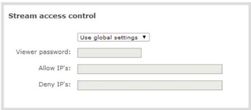
- Select Use these settings from the drop down list; the configuration fields are enabled.

Global LDAP settings are always enforced. Any local settings are in addition to LDAP sign on.
- If desired, specify a password for viewers of this channel; the password appears masked as you type it.

If you have global allow/deny lists or a global user password, you can override the global settings and remove all access control for a channel by selecting Use these settings and leaving all the fields blank.
- If desired, specify allow and deny IPs for viewers of this channel. See Restrict viewers by IP address for more information about allow and deny lists.
- Click Apply at the bottom of the page.
To return a channel to the default (global) access control settings:
- Login to the Admin panel as admin. See Connect to the Admin panel.
- From the Admin panel, click Streaming for the desired channel; the streaming page opens.
- Scroll to the Stream access control section of the page.
- Select Use global settings from the drop down list; the configuration fields are disabled (any changes to the configuration fields are not saved).
- Click Apply at the bottom of the page.
Restrict viewers by IP address
Pearl-2 permits you to restrict which computers can access broadcasts by building a list of allowed and/or denied IP addresses. You can do this at a global level for the system and can also override these settings on a
per-channel basis. Both global and per-channel configuration procedures are described below.

You cannot set per-channel passwords and IP restrictions if you stream using HTTP Live Streaming (HLS).
If your viewer account has a password, your viewers must connect to the system from a computer (or gateway) with a permitted IP address and must also supply the username (viewer) and password before they can view the broadcast.
To restrict access by IP address, you need to know the IP addresses or range of addresses for your viewers. By default, all IP addresses are allowed to connect to the broadcast.
If you're not familiar with creating allow/deny lists, refer to the examples below this procedure for assistance with crafting your lists.

IP address restriction is valid for the viewer only and does not affect the Admin panel or the mobile configuration interface.
To restrict viewers by IP address:
- Login to the Admin panel as admin. See Connect to the Admin panel.
- Select the Access passwords link in the Configuration menu; the password configuration page opens.
- Type allowed IP addresses or address ranges in the Allow IP's field. Separate addresses with a comma.
- Type denied IP addresses or address ranges in the Deny IP's field. Separate addresses with a comma.
- Click Apply.
To restrict viewers of a specific channel by IP address:
- Login to the Admin panel as admin. See Connect to the Admin panel.
- Select the Streaming link for the desired channel; the streaming configuration page opens.
- From the Access Control drop-down, select Use these Settings; local password and Allow/Deny IP lists are enabled.
- If desired, type a password for the viewer in the Viewer Password field.
- Type allowed IP addresses or address ranges in the Allow IP's field. Separate addresses with a comma.
- Type denied IP addresses or address ranges in the Deny IP's field. Separate addresses with a comma.
- Click Apply.
If a user attempts to connect to the stream from a disallowed IP address, access is denied. If connecting by internet browser, the message "IP address rejected." is displayed.
The following table describes the applicable fields.
Table 42 IP Based Restriction Fields
| Label Description/Options | |
| Allow IP's | Enter individual IP addresses or IP address ranges, separated by commas. To specify a range, use a hyphen (-). Optional spaces improve readability.Users connecting from addresses in this list are permitted to view broadcasts from the system, provided their IP address is not in the Deny IP's list.To allow all except IP addresses in the deny list, if any, leave the field blank.You can use the Allow list by itself, or in conjunction with the Deny IP's list as an exception to a rule in the allow list. |
| Deny IP's | Enter individual IP addresses or IP address ranges, separated by commas. To specify a range, use a hyphen (-). Optional spaces improve readability.Users connecting from addresses in this list are not allowed to view broadcasts from the system, unless their IP address is in the Allow IP's list. If a specific IP address is in both list access to the stream is denied.You can use the Deny list by itself, or in conjunction with the Allow IP's list as an exception to a rule in the allow list. |
IP restriction examples
Allow list with distinct IP addresses
The simplest allow/deny list is to use the list of known IP addresses to craft a list of allowed IP addresses. All other addresses are denied access to the broadcast.
For example if your system is accessible on your local area network (LAN) and you want to make sure only the CEO's specific desktop, laptop and tablet computers (with IP Addresses 192.168.1.50, 192.168.1.51, and 192.165.1.75, respectively) can connect to the broadcast, construct the following allow list:
Allow: 192.168.1.50, 192.168.1.51, 192.168.1.75
Allow list with a range of IP addresses
Sometimes you'll want a range of computer IP addresses to connect to your system. This may happen when you have one range of IP addresses assigned to desktop computers (i.e. in the range 192.168.1.1 to 192.168.1.100) and another range assigned to boardroom computers (i.e. the range 192.168.1.200 to
192.168.1.250). If you only want the boardroom computers to connect to broadcasts from the system you can specify the range of boardroom IP addresses rather than needing to type in each individual address. The allow list looks as follows:
Allow: 192.168.1.200-192.168.1.250
Note that we could have specified two of the IP addresses in the previous example as a range.
Allow list with a range of IP addresses and one or more specific IP addresses
Putting the first two examples together, we want to permit access to IP addresses in the range of boardroom computers (192.168.1.200-192.168.1.250) and also want to add the desktop, laptop and tablet computers of the CEO (IP addresses 192.168.1.50, 192.168.1.51, and 192.168.1.75, respectively). Note the first two IP addresses are consecutive, so they can be added as a second range. Add these IP addresses to the list as follows:
Allow: 192.168.1.200-192.168.1.250, 192.168.1.50-192.168.1.51, 192.168.1.75
Your list can have multiple ranges and multiple distinct IP addresses, provided they are separated by commas.
Deny list with distinct IP addresses
Another simple allow/deny list is to use the list of known IP addresses to list specific denied IP addresses. All other addresses are allowed access to the broadcast.
For example imagine your system is accessible on your local area network (LAN) and you want to allow any computer on the LAN can access the stream except your publicly-accessible boardroom (with IP address 192.168.1.211). You can use the following deny list (leave the allow list empty) to permit all computers except the boardroom computer:
Deny: 192.168.1.211
As with allow lists, your deny list can specify a range of IP addresses, and can specify multiple ranges or distinct IP addresses in a comma-separated list.
Allow list with a range of IP addresses, distinct IP addresses and an exception
Building on the previous examples, consider the situation where you want the CEO's computers (192.168.1.50, 192.168.1.51, 192.168.75) and all boardroom computers (192.168.1.200-192.168.1.250) to access the broadcast, with the exception of the public boardroom computer (192.168.1.211). Use both allow and deny lists to create the rule as follows:
Allow: 192.168.1.200-192.168.1.250, 192.168.1.50-192.168.1.51, 192.168.1.75
Deny: 192.168.1.211
Both lists can have multiple ranges and multiple distinct IP addresses, provided they are separated by commas.
Deny list with a range of IP addresses
Converse to the previous examples, consider the situation where you want every computer on the network to access the broadcast, with the exception of the CEO's desktop, laptop and tablet computers. Additionally, boardroom computers should not be permitted with the exception of the cafeteria computer (IP address 192.168.1.222).
The deny list is an "exception" list for the allow list. So to craft the rule described above we need to allow all the computers in the local subnet, then deny specific sub-ranges including two groups of boardroom computers ensuring the cafeteria computer's IP address is not in the deny list:
Allow: 192.168.1.1-192.168.1.250
Deny: 192.168.1.200-192.168.1.221, 192.168.1.223-192.168.1.250, 192.168.1.50-192.168.1.51, 192.168.1.75
Stream to a server
Your Pearl-2 streams to a server when you want to use a CDN or Multicast.
By default, no server streaming is configured. See Stream to a CDN and Stream content using multicast for details on configuring one of these two options.
| Publishing Options Use this option to... | |
| Content Distribution Network (CDN) | Stream web content to many viewers on different Content Delivery Networks simultaneously to any geographical location. A viewer accesses the broadcast from a website using a user name and password, if required. Using a CDN to host your broadcast is highly scalable and makes financial sense to website owners since you do not pay for additional server hardware or routing should your network traffic increase or decrease. Using one or more CDNs to stream live content allows you to reach a large geographically diverse audience and because CDNs perform format conversion, the stream is platform independent.You can control when streaming to a CDN is enabled by using the Admin panel or the touch screen. See Start and stop streaming to a CDN.For more information about streaming to a CDN, see Stream to a CDN. |
| Multicast Streaming | Stream content to a multicast IP address where it can be shared with multiple viewers within the same LAN. All viewers receive the same stream at the same time. Similar to turning on a radio station where all listeners hear the same music at the same time.This delivery method relies on network equipment that supports multicasting and is usually used in high bandwidth corporate LANs and not on Internet-based architectures.This delivery method is useful for training sessions, when there is a specific timeframe when the audience will view the content. For more information about using multicasting for streaming your content, see: Stream content using multicastThis option can be used to stream video and audio to an IP TV or set top box playlist. |
To stream video outside of your LAN, use a CDN or configure port forwarding on your router. Refer to your Network Administrator; network configuration is beyond the scope of this guide.
Streaming to CDNs and multicast streaming is available only when the H.264 codec is selected.
Stream to a CDN
A Content Delivery Network (CDN) relies on geo-diverse CDN servers to receive and disperse web content to the CDN server closest to the user. The closer the server is to the user, the faster the content is delivered. Streaming your content through a CDN allows you to stream any time, anywhere, regardless of the viewing device.
You can publish to any CDN provider that supports incoming streams sent via RTSP announce or RTMP push, and you can publish to several different CDNs simultaneously. Both RTSP and RTMP can be used for live streaming, however not all CDNs or media servers support both formats. Choose the streaming format that your CDN or media server supports. Epiphan has tested with the CDN providers listed here:
https://www.epiphan.com/partners/cdn-partners/. Contact your CDN for a list of supported audio codecs and ensure your Encoding configuration uses one of the supported codecs.
To publish content to a CDN provider, ensure you have:
- a path to the mount point or an XML configuration file (provided by the CDN provider);
- verify which transport protocols your CDN supports;
- a current flash player; and
- select the H.264 codec from the channel's Encoding page.
You can control when streaming to a CDN is enabled by using the Admin panel or the touch screen. See Start and stop streaming to a CDN.
You can also test how your content is streamed by sending your content to Epiphan's CDN. For a list of Epiphan's preferred CDN providers, see: https://www.epiphan.com/partners/cdn-partners/.
Use one of the following links to configure your Pearl-2 for publishing to a CDN:
• To stream content to a CDN using RTSP announce
• To stream content to a CDN using RTMP push
• Stream to a CDN using an XML profile
• Stream to Wowza Streaming Cloud
Start and stop streaming to a CDN
Once you have your CDN streaming configured for RTMP, RTSP, Wowza Streaming Cloud, or Original Livestream, you can control when streaming is enabled and disabled through the Admin panel, the touch screen or Epiphan Live.
Start and stop streaming using the Admin panel
To start (enable) or stop (disable) streaming using the Admin panel:
- Login to the Admin panel as admin. See Connect to the Admin panel.
- From the Admin panel, click the link for your Channel; the menu expands.
- Click Streaming; the channel's Streaming page opens.

-
If streaming is enabled (started), click the Stop streaming button (at the top right corner of the stream) or Stop all at the top of the page; streaming is disabled for either that stream or for all streams, respectively.
-
If streaming is disabled (stopped), click the Start streaming button (at the top right corner of the stream) or Start all at the top of the page; streaming is enabled for either that stream or for all streams, respectively, and a streaming timer appears on the touch screen.
Start and stop streaming using the touch screen's channel monitoring view
From the individual Channel monitoring view you can start and stop streaming in a similar way to how you start and stop recording.
To control streaming from the touch screen:
-
Configure your CDN streaming settings.
-
View the individual channel monitoring page for your channel. See Channel monitoring.
-
If streaming is disabled, there is no way to start it - configure the settings and try again.
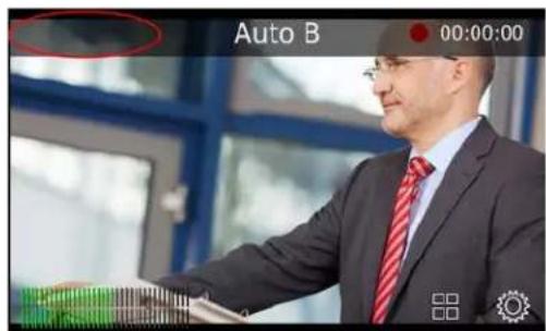
- If streaming is already started, you'll see a flashing blue circle and a timer (indicating how long streaming has been enabled) at the top left corner of the screen. To stop the stream, touch the blue circle.
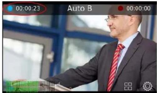
- If streaming is not started, you'll see a grey circle and a timer reading 00:00:00 at the top left corner of the screen. To start the stream, touch the grey circle at the left side of the screen; the text changes to Starting... then to a timer once the server connection is established. If one of your streams is
unable to connect to your server, the circle changes to a yellow error icon as a notification. All other working streams continue. You can fix non-working streams on the Admin panel.

Note you can also tell whether or not your channel is streaming by looking at it in the Grid view:
• If it has a blue dot in the top right corner, it is currently streaming.
- If it has a yellow dot with an exclamation mark, there is a problem with streaming.
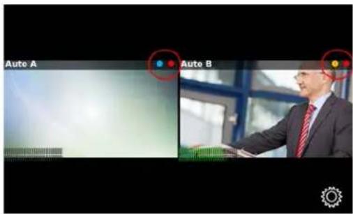
Start/stop streaming using One Touch control
Pearl-2's "One Touch" recording/streaming control allows you to control your recording and streaming across any number of specified channels and recorders simultaneously with the touch of a button. See One Touch streaming and recording control for more information.
To control streaming using One Touch control:
- Configure your CDN streaming settings.
- Configure your desired channels for One Touch streaming in the admin panel (all channels are enabled for One Touch streaming by default) (see Specify channels for One Touch streaming).
- Touch the One Touch control icon in the lower portion of the touch screen to display the One Touch control screen. Note that you can customize how and when the One Touch control screen is displayed in Pearl-2's admin panel (see Customize how One Touch control is displayed).
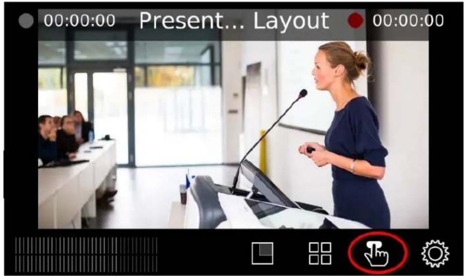

If the gear icon is not visible on the touch screen, tap the screen once to activate the control buttons. If the system settings button is still not visible, it is disabled in the system's touch screen configuration. See Configure the touch screen to enable system information.
- From the One Touch control screen, simply press Start to begin streaming. This starts each stream where the Single touch control check box is checked. For more information on understanding the elements in the One Touch control screen, see Understand and use One Touch control.)

flowchart
graph LR
    A["Start\nRecording 0/0 Streaming 0/1"] --> B["Stop\nRecording 0/0 Streaming 1/1"]
- To stop streaming, press Stop.
Start and stop streaming using Epiphan Live
You can control the streaming (and recording) of channels directly from the Epiphan Live Dashboard interface. (See Accessing Epiphan Live for information about logging in to Epiphan Live.)
Streaming (and recording) control buttons are located under the Channels heading.
For each channel, the stream control is the left-most button containing the "signal" icon, and the recording control is the right-most button containing the circle icon.
![Channels Channel 2 00:00:00 00:00:00 External [192.168.0.205] Not set 00:00:00](/content/2026/06/1365921/images/2388255538483c312e30c1ebc5ffb8f98e6a6eed7bb12e3786014c4361a7275a.jpg)
When a channel is not being streamed or recorded, the streaming and recording buttons are gray in color and their respective timers are set to 00:00:00. If streaming has not been configured in the Admin panel, the streaming button will display the text "Not set". See Stream to a server to learn how to configure streaming in the Admin panel.
You can preview a channel by clicking on its name to display a small dropdown thumbnail view.
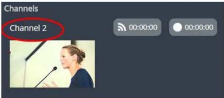
To start streaming and recording a channel, simply click (or press) the channel's streaming and/or recording buttons.

When clicked, the streaming button turns blue in color and the recording button turns red. The timer contained within each respective button also begins to count upward.
Alternatively, you can also control streaming and recording of a channel via the Dashboard's monitoring panels. See Configuring Dashboard panels for visual confidence monitoring for more information.
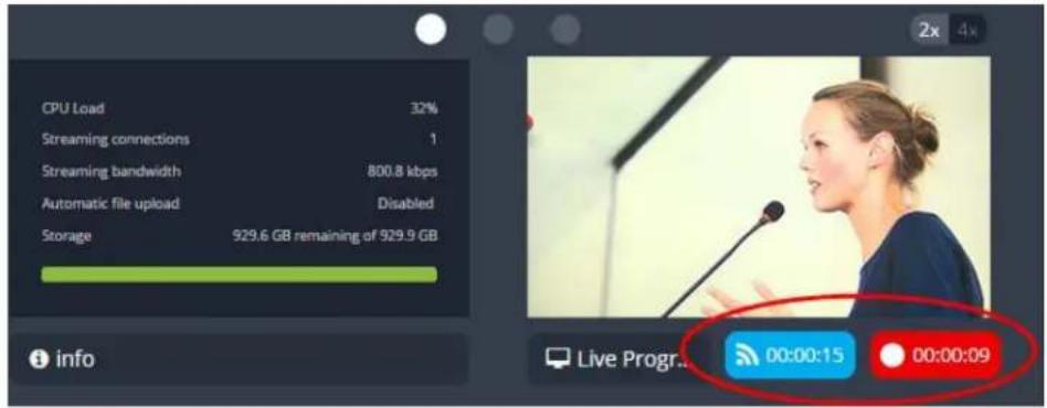
If a stream is not able to publish, the streaming button for that line flashes blue and displays "ERROR". The stream can be fixed in the Admin panel.

In this case, check the streaming configuration settings for your channel in the Admin panel. (See Stream to viewers
To learn more about the Epiphan Live control interface, see Epiphan Live.
To stream content to a CDN using RTSP announce
- Login to the Admin panel as admin. See Connect to the Admin panel.
- From the Admin panel, click a Channel; the menu expands.
- Click Streaming; the channel's Streaming page opens.
- Scroll to the Stream to a server section of the page.
- Click the New stream button to open the drop-down menu.
- Choose RTSP announce from the drop-down menu.
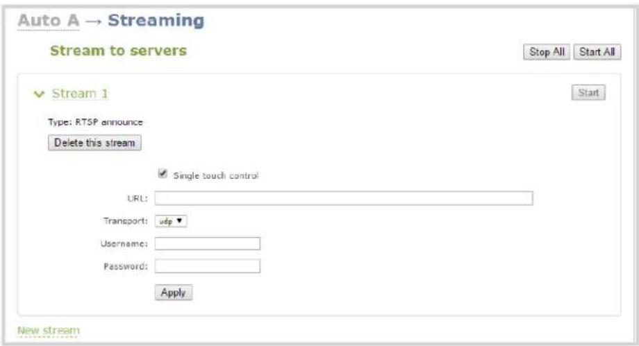
- Once selected, the stream options open. To rename the stream, click on the current name and type a different name. Then pressing Enter.
- The stream can be operated via One Touch streaming and recording control. You may remove this functionality for this individual stream by deselecting the Single touch control check box.
- Enter the ingestion point url provided by the CDN or media server.
- Select UDP or TCP from the drop-down menu. Verify which transport protocols your CDN provider supports.
- Enter a user name and password.

The CDN provider assigns a user name and password to authenticate the publisher. Contact the CDN provider for your log in credentials.
-
Click Apply.
-
When ready to begin streaming, you may click Start to start that individual stream, or Start all to simultaneously start this stream and any other streams you have configured. See Start and stop streaming to a CDN for instructions on starting streaming from the touch screen or see Controlling streaming and recording using Epiphan Live for instructions on streaming control using the Epiphan Live control interface.
To stream content to a CDN using RTMP push
This is the most common method to stream to a CDN, as it is used by many CDNs including both Facebook Live and YouTube.
-
Login to the Admin panel as admin. See Connect to the Admin panel.
-
From the Admin panel, click a Channel; the menu expands.
- Click Streaming; the channel's Streaming page opens.
- Click the New stream button to open the drop-down menu.
- Choose RTMP push from the drop-down menu.

- Once selected, the stream options open. To rename the stream, click on the current name and type a different name. Then pressing Enter.
- The stream can be operated via One Touch streaming and recording control. You may remove this functionality for this individual stream by deselecting the Single touch control check box.
- Enter the ingest point URL provided by the media server or CDN.
- In the Stream name field, enter the stream name you configured with the CDN.
- Enter the CDN user name and password.

The CDN provider assigns a user name and password to authenticate the publisher. Contact the CDN provider for your log in credentials.
-
Click Apply.
-
When ready to begin streaming, you may click Start to start that individual stream, or Start all to simultaneously start this stream and any other streams you have configured. (See Start and stop streaming to a CDN for instructions on starting streaming from the touch screen or see Controlling streaming and recording using Epiphan Live for instructions on streaming control using the Epiphan Live control interface.)
-
You may delete the stream at any time using the Delete this stream button.
Stream to a CDN using an XML profile
Some CDNs provide an XML file for easy configuration. If you're using one of these services, you can use the following setup process.
- Login to the Admin panel as admin. See Connect to the Admin panel.
- From the Admin panel, click a Channel; the menu expands.
- Click Streaming; the channel's Streaming page opens.

- Select use profile XML from the New stream drop-down menu; a file browser window opens.
- Select the XML profile supplied by your CDN and click OK; the configuration is read from the XML file and applied.

-
Click Apply.
-
To control streaming, click either Stop and Start to control this individual stream, or Stop all and Start all to control all streams simultaneously. (See Start and stop streaming to a CDN for instructions on starting streaming from the touch screen or see Controlling streaming and recording using Epiphan Live for instructions on streaming control using the Epiphan Live control interface.)
Stream to Wowza Streaming Cloud
To set up streaming via Wowza Cloud, you first need to sign in to the Wowza Streaming Cloud web site and create a new Live Stream (when asked to select a camera or encoder type, select Epiphan).
Once the stream is created, you'll see a Connection Code on the stream's Overview page; this code is required to complete the streaming set-up process.
- Login to the Admin panel as admin. See Connect to the Admin panel.
- From the Admin panel, click a Channel; the menu expands.
- Click Encoding; the channel's Encoding page opens.

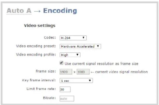
- Configure Encoding settings accordingly, ensuring the Codec selected is H.264.

Configuring audio is optional. Supported formats are limited to MP3 and AAC. Due to RTMP restrictions, MP3 48 kHz is not supported.
- Click Apply.
- Under the selected channel, click Streaming; the channel's Streaming page opens.

- Click the New stream button to open the drop-down menu.
- Select Wowza Cloud from the drop-down list.

- Enter the connection code obtained from the Wowza Streaming Cloud set-up into the Connection code field.

- Click Set to pair the channel on Epiphan's encoder with the live stream on Wowza Cloud; an icon appears to show you the connection is validating. Once validated, the stream name you configured in Wowza Cloud appears.
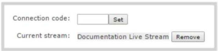
- When ready to begin streaming, there are two steps to take.
a. Click the Start Transcoder button. The state changes from stopped to starting, then to started. If you log into your stream on Wowza Cloud you'll see the stream is started, but there is no video detected. (You can also start the transcoder through the Wowza Cloud interface, by clicking Start Stream.)

This action commences your session charges with Wowza Cloud.

b. To start sending video to the Wowza Cloud, you may either click Start to start that individual stream, or Start all to simultaneously start this stream and any other streams you have configured. (See Start and stop streaming to a CDN for instructions on starting streaming from the touch screen or see Controlling streaming and recording using Epiphan Live for instructions on streaming control using the Epiphan Live control interface.

- When the connection to Wowza Cloud has been established, the stream name appears on the channel's Status page.
Connections
Stream name
Publish
Client IP
Wowza Streaming Cloud: Documentation Live Stream
Bitrate
6701 kbps
Bytes transmitted
76128 KBytes

After clicking either Transcoder or Publish Start buttons, there can be a short delay before the stream is established.
Stop streaming to the Wowza Streaming Cloud
When you are done streaming, be sure to stop the Wowza Transcoder by either returning to the channel's streaming page and pressing the Stop Transcoder button, or by logging into the Wowza Cloud and stopping the stream. Charges from Wowza continue until the Wowza Cloud stream is stopped in one of these two ways.

Stopping the stream by using the touch screen, pressing Stop or by the Epiphan Live Publish button does not stop the charges applied by Wowza.
Stream to Original Livestream
To set up streaming via the Original Livestream service, you first need to sign in to your Original Livestream account and create a new stream.
To configure streaming on your Pearl-2:
- Login to the Admin panel as admin. See Connect to the Admin panel.
- From the Admin panel, click a Channel; the menu expands.
- Click Encoding; the channel's Encoding page opens.
- Configure Encoding settings accordingly for best results: set the Codec to H.264, the Resolution to 640x480, the Frame rate to 30 fps, the Bitrate to 4 kbps, and the audio to 64 kbps AAC.

Configuring audio is optional. Supported formats are limited to MP3 and AAC. Due to RTMP restrictions, MP3 48 kHz is not supported.
- Click Apply.
- Under the selected channel, click Streaming; the channel's Streaming page opens.
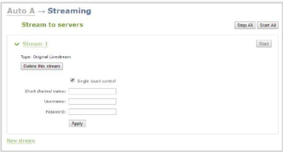
- Click the New stream button to open the drop-down menu.
- Select Original Livestream from the drop-down list.

- Enter the channel name in the Short channel name field.
- Enter your Original Livestream Username and Password in the next two fields.
- Click Apply.
- When ready to begin streaming, you may click Start to start that individual stream, or Start all to simultaneously start this stream and any other streams you have configured. (See Start and stop streaming to a CDN for instructions on starting streaming from the touch screen or see Controlling streaming and recording using Epiphan Live for instructions on streaming control using the Epiphan Live control interface.)
When the connection to Original Livestream has been established, the stream name appears on the channel's Status page, similar to this example from Wowza Streaming Cloud.

After clicking Apply, there may be a short 2-3 minute delay before the live stream is displayed.
Stream content using multicast
A multicast stream consists of one stream distributed to many viewers via a multicast-capable network. You are only able to broadcast to one multicast network at a time, but you may broadcast to a multicast network and any number of non-multicast CDNs.
Pearl-2 supports multicast streaming content to an IP TV or a set-top box playlist when the stream format is MPEG-TS. You may only stream to one multicast network at a time.

Note that only one multicast network may be used simultaneously. So if you select MPEG-TS UDP push, MPEG-TS RTP/UDP push or RTP/UDP push, you are not able to select any of the others, and you must delete the stream to select a different multicast network. Adding, removing, or changing the settings for any of these three multicast publishers stops any current streaming or recording session.
The following procedures outline the steps to distribute your content using multicast streaming:
• MPEG-TS streams using RTP/UDP push
• MPEG-TS streams using UDP push
• Multicast streaming using RTP/UDP
MPEG-TS streams using RTP/UDP push
Before configuring your channel for MPEG-TS streaming, ensure the following codecs are configured:
- Video - H.264
• Audio - MP3 or AAC, if audio is configured.
To configure your channel for MPEG-TS using RTP/UDP push:
- Login to the Admin panel as admin. See Connect to the Admin panel.
- From the Admin panel, click a Channel; the menu expands.
-
Click Streaming; the channel's Streaming page opens.
-
Click the New stream button to open the drop-down menu.
- Choose MPEG-TS RTP/UDP push from the drop-down menu.

- Enter the destination multicast IP address where the broadcast can be viewed.

A IPv4 multicast address range is an address between 224.0.0.0 to 239.255.255.255. Contact your System Administrator for the specific address to use.
- Enter the destination port number through which the media will stream.
- Perform one of the following:
a. If you do not want to advertise your stream to a media player over a local network, go to the last step of this procedure; or
b. To advertise your stream to a media player over a local network, follow the steps below.
- Enable the SAP announcement checkbox to advertise your stream over a local network. When the checkbox is enabled and a multicast IP address is configured, your stream is displayed in the playlist of the local media player.
- Enter a multicast IP address in the SAP announcement IP field. If your media player is configured to receive multicast streams from an IP address that is different from the default address 224.2.127.254, you may need to contact your system administrator for a specific multicast IP address.
- Enter a channel number in the Channel number field to identify your stream in the media player. By default, the Channel number is the channel identifier.

When a channel number value is not specified, viewers cannot select a channel from the set-top box or Smart TV.
- Enter a name for a group of streams in the text box next to Group name. Since media players simply present a list of available streams, you can organize your streams into multiple folders or in cases where folders are not displayed, use dot separator hierarchy to help your viewers filter out unwanted streams by category.
- Click Apply.
- Click the Info menu option of the Admin panel. An Info page opens displaying stream information.
To view the stream from a media player, open the URL in a media player, for example:
rtp://@ip:port or in the case of the sample configuration in the figure shown above:
rtp://@226.10.24.32:7000
To view the stream when SAP announce has been set and the stream is advertised on a media player, set-top-box or Smart TV, refer to Viewing with Session Announcement Protocol (SAP).
MPEG-TS streams using UDP push
Before configuring your channel for the MPEG-TS streaming, ensure the following codecs are configured in the encoding section:
- Video - H.264
- Audio – MP3 or AAC, if audio is configured.
To configure MPEG-TS with UDP push:
- Login to the Admin panel as admin. See Connect to the Admin panel.
- From the Admin panel, click a Channel; the menu expands.
- Click Streaming; the channel's Streaming page opens.
- Click the New stream button to open the drop-down menu.
- Select MPEG-TS UDP push from the drop-down menu.

- Enter the destination multicast IP address where the broadcast can be viewed.

A IPv4 multicast address range is an address between 224.0.0.0 to 239.255.255.255. Contact your System Administrator for the specific address to use.
- Enter the destination port number through which the media will stream.
- Perform one of the following:
a. If you do not want to advertise your stream to a media player over a local network, go to the last step of this procedure; or
b. To advertise your stream to a media player over a local network, follow the steps below.
- Enable the SAP announcement checkbox to advertise your stream over a local network. When the checkbox is enabled and a multicast IP address is configured, your stream is displayed in the playlist of local media players.
- Enter a multicast IP address in the SAP announcement IP field. If your media player is configured to receive multicast streams from an IP address that is different from the default address 224.2.127.254, you may need to contact your system administrator for a specific multicast IP address.
- Enter a channel number in the Channel number field to identify your stream in the media player. By default the Channel number is the channel identifier.

When a channel number value is not specified, viewers cannot select a channel from the set-top box or Smart TV.
- Enter a name for a group of streams in the text box next to Group name. Since media players simply present a list of available streams, you can organize your streams into multiple folders or in cases where folders are not displayed, use dot separator hierarchy to help your viewers filter out unwanted streams by category.
- Click Apply. To view the stream, open the URL in a media player, for example:
udp://@ip:port
For example: udp://@226.10.24.32:7000
To view the stream when SAP announce has been set and the stream is advertised from a media player, set-top-box or Smart TV, refer to Viewing with Session Announcement Protocol (SAP).
Multicast streaming using RTP/UDP
- Login to the Admin panel as admin. See Connect to the Admin panel.
- From the Admin panel, click a Channel; the menu expands.
- Click Streaming; the channel's Streaming page opens.
- Click the New stream button to open the drop-down menu.
- Choose RTP/UDP push from the drop-down menu.
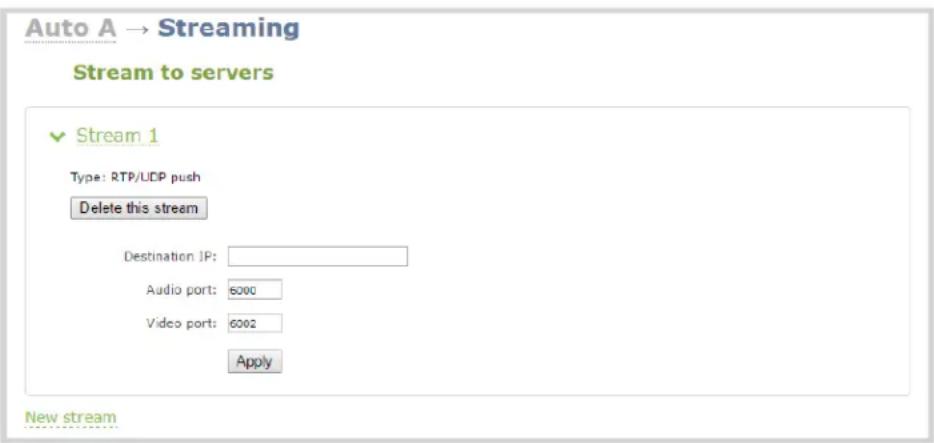
- Enter the destination multicast IP address.
- Enter the port number through which the audio will stream.
- Enter the port number through which the video will stream.

Audio and video use nearby port numbers (
-
Click Apply; an SDP file is generated and available from the channel's Status page.
-
Click the SDP file to download it. If asked, specify a name and location for the SDP file.
-
Share the file with your viewers!
Viewing with Session Announcement Protocol (SAP)
When SAP Announce is configured for a stream that uses UDP streaming, the stream is advertised over the local network. Local viewers can view the stream using a software or hardware media player. Viewers are presented with a list of available channels, similar to a television menu. Viewers need only click on a stream and the video is streamed to their desktop, mobile or tablet. To configure SAP announce, go to Stream content using multicast.
Your stream is advertised by the metadata title, if one was configured under Branding, otherwise it is identified by its channel identifier. For a description of how to set the metadata, refer to Add channel metadata.
When browsing from a VLC media player, streams are advertised by their channel identifier and are organized by the group name. When browsing from an XBMC media player, streams are advertised by the stream's metadata title (if configured), otherwise streams are advertised by their channel identifier.
-
Ensure the stream has SAP announcement enabled, otherwise, it is not advertised in the media player's playlist.
-
Ensure the SAP announcement IP is a multicast IP address.

Some media players, for example Exterity receivers, listen for SAP announcements on a specific multicast address 239.255.255.255. If your audience is using Exterity to view your stream, you must change the SAP announcement IP address to 239.255.255.255.
-
Launch a media player. The following steps are based on a VLC media player and may be different for other media players.
-
Click View from the menu; a drop-down menu opens.
-
Select Playlist. A Playlist window opens. The right-hand panel indicates the playlist is empty.
-
From the side menu, click Network streams (SAP). The playlist is populated with all streams in your network that are SAP announcement enabled. If you specified a Group Name when you configured the publish stream the stream will be listed in folder identified by the group name.
In the example below, two streams D2P83658.vga and D2P83658.video are organized in a folder by their group name.

- Click on a live stream; the stream plays in the media player window.
Stream to a media player or smart TV
Your Pearl-2 can use UPnP and SAP to stream to set top boxes, digital signs, smart TVs and other digital media players.
The following table gives an overview of each option.
| Publishing Options Use this option to... | |
| UPnP | Using the Universal Plug and Play (UPnP) networking protocol, your Pearl-2 can be discovered and can stream to software and hardware media player set-top-boxes and Smart TVs with ease. |
| SAP | Viewing with Session Announcement Protocol (SAP)SAP (session announcement protocol) is a protocol for broadcasting multicast session information. Media players can see the announcement or can use the multicast SDP file (session description file) directly. |

To stream video outside of your LAN, use a CDN or configure port forwarding on your router. Refer to your Network Administrator; network configuration is beyond the scope of this guide.
Stream content using UPnP
Using the Universal Plug and Play (UPnP) networking protocol, your Pearl-2 can be discovered and can stream to software and hardware media players, set-top-boxes and Smart TVs with ease. If UPnP is enabled, the system automatically establishes communication with media players on the network.
UPnP uses MPEG-TS over HTTP with the H.264 codec and MP3 or AAC audio encoding (or no audio). You can only access live streams or recordings that meet these requirements.

For security reasons the default behavior prevents UPnP access to live streams and recorded files.
This section covers the following topics:
- Enable UPnP
- Disable UPnP
• Viewing with UPnP
• Play directly to a media player
• Auto-restart playback to a UPnP device
• Change UPnP device name

Some players will not be able to access the stream or saved recordings if a viewer password is set. If needed, see User administration to clear the viewer password.
The topics in this chapter include how to enable and disable UPnP and how to control media players from Pearl-2. To choose recordings or live streams from your media player, see Play directly to a media player.
Enable UPnP
Enable UPnP to allow digital media players on the network to browse for recorded media files or live streams from your system. There are two steps required to enabled UPnP, enabling UPnP for the system (including setting a share name) and enabling UPnP per channel or recorder. By default, UPnP is disabled at the system level and for each channel.

Streams and MPEG-TS recorded files must use the supported codecs: H.264 with MP3 or AAC audio. Having a viewer password could prevent the ability to use UPnP.
Step 1: Enable UPnP at the device level
To enable UPnP:
- Login to the Admin panel as admin. See Connect to the Admin panel.
- Click the UPnP link in the Configuration section; the UPnP configuration page opens.
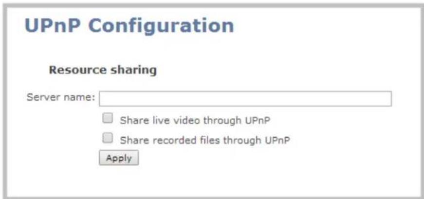
- Enter a name in the Server name field. If no name is provided the server name will be the system's serial number.
- Select whether you want to share live video and recorded files.
- Click Apply.
- If no live stream is available that meets the criteria for UPnP, a message is displayed in the Play on service start section of the page.

- Otherwise, the Play on service start section shows a drop-down list of what can be streamed.
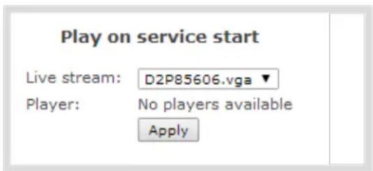
Step 2: Enable UPnP for channels and/or recorders
After enabling UPnP for the device (for one or both of live stream sharing and recorded file sharing) you need to enable sharing for each channel or recorder you wish to share.
Enable UPnP sharing for the channels or recorders you want to share:
- For channels (live streaming):
a. Click the Streaming link for the desired channel; the Streaming page opens.

a. Click the Share via UPnP check box (if not checked).
b. Note, if you have not already enabled UPnP at the server level (see above), you are prompted with a message "UPnP live video sharing is not enabled with this device, to fix it, click here". Once you click the text "to fix it click here", the text changes to "will be fixed". The UPnP service will be started when you click Apply.
c. Click Apply.
2. For channels (recorded files):
a. Click Recording for the desired channel; the channel's recording page opens.
b. Click the word change next to the list of what is being recorded; the recording options expand.

c. Click the Share via UPnP check box (if not checked).
d. Note, if you have not already enabled UPnP at the server level (see above), you are prompted with a message "UPnP file sharing is not enabled with this device, to fix it, click here". Once you click the text "to fix it click here", the text changes to "will be fixed". The UPnP service will be started when you click Apply.
e. Click Apply.
- For recorders:
a. Click the link for the recorder from the Recorders menu; the recorder's configuration page opens.
b. Click the word change next to the list of what is being recorded; the recording options expand.

c. Click the Share via UPnP check box (if not checked).
d. Note, if you have not already enabled UPnP at the server level (see above), you are prompted with a message "UPnP file sharing is not enabled with this device, to fix it, click here". Once you click the text "to fix it click here", the text changes to "will be fixed". The UPnP service will be started when you click Apply.
e. Click Apply.
You can now browse for your server from your digital media player.
Disable UPnP
By default, UPnP sharing is disable for the device, and for each channels and recorder. If you enabled UPnP sharing it for a particular broadcast, you may want to disable UPnP sharing after the broadcast is complete. You can choose to disable access to live streams, recorded files, or to the whole system.
To disable UPnP for a channel or recorder:
- For channels:
a. Click the Streaming link for the desired channel; the Streaming page opens.
b. Deselect the Share via UPnP check box (if checked).
c. Click Apply
- For recorders:
a. Click the link for the recorder from the Recorders menu.
b. Click the word change next to the list of what is being recorded; the recording options expand.

a. Deselect the Share via UPnP check box (if not checked).
b. Click Apply.
To disable UPnP globally (for the whole system):
- Login to the Admin panel as admin. See Connect to the Admin panel.
-
Click the UPnP link in the Configuration section; the UPnP configuration page opens.
-
Deselect Share live video through UPnP to stop sharing live video.
- Deselect Share recorded files through UPnP to stop sharing recorded files.
- Click Apply; UPnP sharing is disabled.
Viewing with UPnP
Using a software or hardware media player, you can browse for files or streams with Universal Plug and Play (UPnP). UPnP uses MPEG-TS over HTTP with the H.264 codec and MP3 or AAC audio encoding (or no audio). You can only access live streams or recordings that meet these requirements.

For security reasons the default behavior prevents UPnP access to live streams and recorded files. To enable UPnP, see Enable UPnP

Some players cannot access the stream or saved recordings if a viewer password is set. If needed, see Remove user passwords to clear the viewer password.
When browsing via UPnP your Pearl-2 is displayed by the server name you set, or it's product serial number.
For example, when browsing from a Windows computer, you will see a list of media devices that includes Pearl-2:
![Media Devices (14) [92033] View device webpage MON]LT23B550 Open Media Player Create shortcut EPITHINK-THINK: EpiThink: Properties BCD95191 NI PC25-7-32BIT: admin:](/content/2026/06/1365921/images/2f698765398d5a7c1cb3be6df64c7b3633471a644897973ff96fba35fd893379.jpg)
Live streams
When you open the device from Windows Media Player, you'll see a list of the available channels you can stream under the Videos tab. From other digital media players, the channel list can be under a Live Streams folder.
With Windows Media Player, double click to open any channel and press Play to start the stream. Using your digital media player, select a live stream and press play.
Recorded files
Recorded files are shown in the Recorded Files folder. Files are organized by the channel or recorder from which they were recorded. Windows Media Player shows the recorder files side by side with the channels and other digital media players show the recorded files in a file tree format, see below.
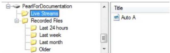
UPnP can also be used to directly play a recording to the digital media player, or to set a media player to automatically play a particular live stream after reboot of Pearl-2. See Stream content using UPnP and Play directly to a media player.
Play directly to a media player
If your digital media player is UPnP enabled, Pearl-2 can play direct the media player to play recorded files, without browsing through menus in the player.

Recorded files must be in MPEG-TS format and use the supported codecs: H.264 with MP3 or AAC audio. Having a viewer password could prevent the ability to use UPnP.
To play directly to a media player:
- Login to the Admin panel as admin. See Connect to the Admin panel.
- Ensure Share recorded files through UPnP is enabled on your Pearl-2 and for the channel or recorder you wish to share. (See Enable UPnP.)
- Go to the recorded files list for the desired channel or recorder. (See View list of recorded files.)
- From the list of files, select the file you want to play and click on the Play To icon for the file; a list of visible digital media players is displayed.
- Select a media player; the recording plays on the screen(s) connected to the media player.
Auto-restart playback to a UPnP device
In unmanned situations such as industrial applications and digital signs, it is useful to automatically have a stream played to a digital media player, even if Pearl-2 restarts.
To configure auto-restart of a stream to a media player:
-
Login to the Admin panel as admin. See Connect to the Admin panel.
-
Click the UPnP link in the Configuration section; the UPnP configuration page opens.
- Scroll to the Play on service start section.
- Select a stream to use from the Live stream drop-down list.
- Select a digital media player from the Player drop-down list. (Digital media players on your network that support UPnP playback will automatically appear in the drop-down list.)
- Click Apply.

Only a single stream and player combination can be configured for auto play. The channel's UPnP configuration must be enabled for it to appear.
Change UPnP device name
You can configure the UPnP server name that appears for your Pearl-2. By default, if you left the server name field blank when enabling UPnP, the server name is the system's serial number.
To change the UPnP server name:
- Login to the Admin panel as admin. See Connect to the Admin panel.
- Click the UPnP link in the Configuration section; the UPnP configuration page opens.
- Highlight and delete the text in the Server name field, if any.
- Type a new server name. Use characters A-Z, a-z, 0-9, _, :, @, ^, #, -. {}, [], ().
- Click Apply; the name changes.
Samples of stream settings
When choosing your stream settings it is important to consider the stream content. When streaming fast moving video, it's best to choose a higher bitrate and frame rate whereas if you're streaming a slide presentation you can save on bandwidth and system processing by lowering the bitrate and frame rate. Stream setup is a matter of balancing quality and system resource usage.
To help you to achieve this balance, the following tables list the recommended settings when streaming video and slide content from a PC, Mac or tablet.
Streaming video content
The table below provides suggested settings to maximize your video quality while minimizing system resource usage when streaming video content from your system.
| Option Setting | |
| Codec H.264 | |
| Video encoding preset Hardware accelerated | |
| Video encoding profile Main | |
| Key frame interval 2 sec | |
| Limit frame rate 30 | |
| Bitrate | 4 Mbps for HD; 6 Mbps for Full HD; 12 Mbps for 4K UHD^4K |
| Audio format PCM 22 KHz |
Streaming slide content
The table below provides suggested settings to maximize your stream quality while minimizing system resource usage when streaming slide content from a PC, Mac or tablet.
| Option Setting | |
| Codec H.264 | |
| Video encoding preset High Quality | |
| Video encoding profile High | |
| Key frame interval 2 sec | |
| Limit frame rate 15 | |
| Bitrate | 4 Mbps for HD; 6 Mbps for Full HD; 12 Mbps for 4K UHD^4K |
| Audio format PCM 44 KHz |
PART 4: Record
Your Pearl-2 encodes the video and audio it captures. Not only can you stream this content, but you can also simultaneously record it. In fact, if you're streaming a picture in picture layout or low quality streams, you may even want to create separate channels to also record each input at full frame size and with a high bitrate so you have the best possible digital media for future re-use or post-processing.
If you choose to record your channels, Pearl-2 stores the recorded files on the system's amply-sized hard drive and provides you a variety of automatic or manual mechanisms to download the files.
This section discusses the following topics related to recording:
• What is a recording?
- Recorders
- Recorded files
- File and recording transfer
- Local FTP server
What is a recording?
Your Pearl-2 can record the output from each channel. (See Recorders for information on creating multi-track recorders using multiple channels.) Recordings are very robust and crafted so that even in the case of accidental system shutdown, recording files are closed off and playable.
You can choose to record simultaneously while streaming, or record without streaming.
This section describes the following topics for creating and configuring recordings via the Admin panel.
- Recording basics
• Record a channel via the Admin panel
• Record a channel via the touch screen
• Record a channel via Epiphan Live
• Record a channel via the touch screen - Configure recording file size and type
- Restart recording
Recording control is easily performed through the Admin panel, but can also be set up for third party tools using our APIs. See Control with HTTP commands and Control with RS-232 / serial port for information on controlling recordings with third party tools.
See Recorded files to learn how to download the recorded files.

Recording can also be controlled via the Epiphan Live control interface. See Controlling streaming and recording using Epiphan Live for more information.
Recording basics
While recording a channel or recorder, a new file is created each time the maximum time or size limit is met. Additionally, when recording a multi-channel recorder or a multi-source layout channel, a new file is created if an additional source is added to the recorder.
Physically removing the source (e.g. unplugging it) or otherwise interrupting the signal to the source does not affect recording, and the recording will include the configured No Signal image. When recording auto channels, a new recording is made when the input changes from one to another due to signal loss.
You can create AVI, MOV, MP4 or MPEG-TS recordings. Two MP4 formats are available: progressive MP4 and MP4-fragmented. See Configure recording file size and type to learn how to change the recorded file type.
Epiphan has tested with the following players. See Troubleshooting for known player issues.
Table 43 Tested Media Players
| Operating System Tested Players | |
| Mac OS | ·QuickTime 10.3·QuickTime 7.6.6+·VLC 2.2.4·Playback Pro 2.3.2·Final Cut Pro 10.3.2·Adobe Premiere Pro CC 2017 |
| Windows | ·QuickTime 7.6.6+·VLC 2.2.6·Windows Media player 12+·Movies & TV (Windows 10)·Adobe Premiere Pro CC 2015 |
| Linux | ·MPlayer·VLC 2.2.2 |
| HTML 5 Browsers (Windows) | ·Google Chrome 37+ (works with MOV and MP4 files using H.264 codec) |

Not all media players and editors support all recording formats, such as the more modern MP4-fragmented format. To playback MOV files created by Pearl-2, we recommend using a newer player.
Record a channel via the Admin panel
Each channel has a configuration page that allows you to start, stop and configure recordings.
To start and stop channel recording:
- Login to the Admin panel as admin or operator. See Connect to the Admin panel.
- Click the name of the desired channel; the channel menu expands.
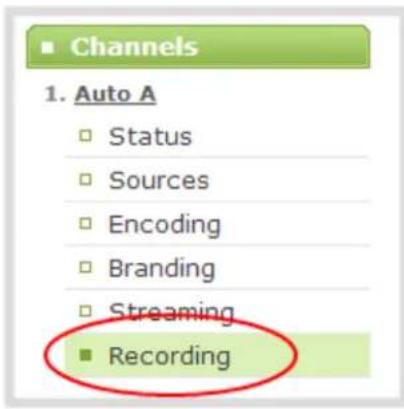
- Click the Recording link for the channel; the Recording page appears.
- To start recording:

a. Click the Start button; the recording starts and a timer indicates how long it has been recording.

If the Start button is not active, there are no active sources for this channel or recorder. Check your inputs to ensure signals are working as expected.
b. You may browse away from the page without affecting the recording. When the page refreshes, the channel number is displayed in red to indicate recording is underway.

c. The system continues to record this channel (and any concurrent recordings) until it is stopped. If the system runs out of storage space, the oldest recorded file is deleted to make room for the new recording. The recording is broken into multiple files as defined by the channel configuration. See Configure recording file size and type.
- To stop recording:
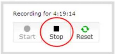
a. Click the Stop button on the given channel's Recording page. The channel number changes to black next time the Admin panel is refreshed (by clicking a link or refreshing the page).
Record channels and recorders (using One Touch control)
Pearl-2's "One Touch" recording/streaming control allows you to control your recording and streaming across any number of specified channels and recorders simultaneously with the touch of a button. See One Touch streaming and recording control for more information.
To control recording using One Touch control:
- Login to the Admin panel as admin or operator. See Connect to the Admin panel.
- Configure your desired channels and/or recorders for One Touch control in the admin panel (all channels are enabled for One Touch recording by default) (see Specify channels and recorders for One Touch recording).
- Touch the One Touch control icon in the lower portion of the touch screen to display the One Touch control screen. Note that you can customize how and when the One Touch control screen is displayed
in Pearl-2's admin panel (see Customize how One Touch control is displayed).
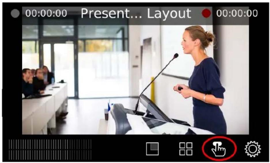

If the On Touch Control icon is not visible on the touch screen, tap the screen once to activate the control buttons. If the system settings button is still not visible, it is disabled in the system's touch screen configuration. See Configure the touch screen to enable system information.
- In the One Touch control screen, simply press Start to begin recording. For more information on understanding the visual elements in the One Touch control screen, see Understand and use One Touch control.

- To stop recording, press Stop.
Record a channel via Epiphan Live
You can control the recording of channels and recorders directly from the Epiphan Live Dashboard interface. (See Accessing Epiphan Live for information about logging in to Epiphan Live.)
Streaming (and recording) control buttons are located under the Channels heading.
For each channel, the stream control is the left-most button containing the "signal" icon, and the recording control is the right-most button containing the circle icon.
![Channels Channel 2 00:00:00 00:00:00 External [192.168.0.205] Not set 00:00:00](/content/2026/06/1365921/images/d944a88e9df6a1d3a50e9beb0ebe9cd962ec2d6a4e2154e782e2e6eeab6e2d9b.jpg)
When a channel is not being streamed or recorded, the streaming and recording buttons are gray in color and their respective timers are set to 00:00:00.
You can preview a channel by clicking on its name to display a small dropdown thumbnail view.
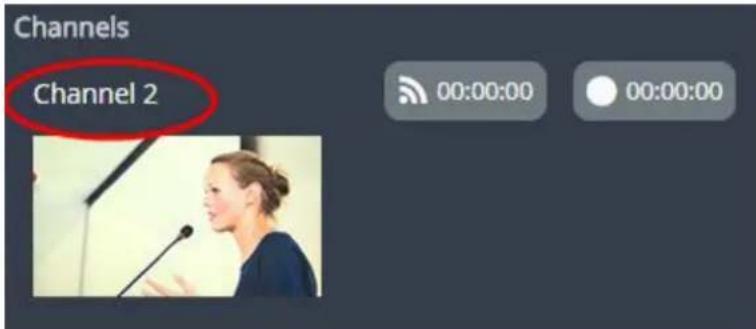
To start recording (and streaming) a channel, simply click the channel's recording (and/or streaming) buttons.
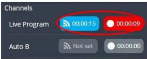
When clicked, the streaming button turns blue in color and the recording button turns red. The timer contained within each respective button also begins to count upward.
Alternatively, you can also control streaming and recording of a channel via the Dashboard's monitoring panels. See Configuring Dashboard panels for visual confidence monitoring for more information, and the section on Epiphan Live also contains more information on managing Your Recordings.

Record a channel via the touch screen
Pearl-2's touch screen gives you freedom to start and stop recording without needing to log in to the Admin panel.
Simply scroll to the channel you wish to control and press the start or stop recording button.


The touch screen may be configured to be always off, to prevent channel preview, or to prevent recording control. If you are unable to follow the instructions below, see the Configure the touch screen
To start recording:
- If necessary, tap the screen once to turn it on or to turn on the screen overlay.
- If the grid view is showing, tap the channel for which you wish to control recording; the screen displays the channel.
- If necessary, tap the screen once to display controls on the channel view.
- Touch the red record button at the top right of the screen; recording starts and a timer is displayed to show the length of the recording.

To stop recording:
- If necessary, tap the screen once to turn it on.
- If the grid view is showing, tap the channel for which you wish to control recording; the screen displays the channel.
- If necessary, tap the screen once to display controls on the channel view.
- Touch the red record button at the top right of the screen; recording stops and the timer disappears.

Configure recording file size and type
By default, recorders and channels record to AVI files. When the recording reaches 30 minutes in length or a file size of 500 MB (whichever occurs first), the system closes the current recording file and opens a new one. This is done seamlessly with no loss in recorded data.
You may find it useful to have recordings divided this way for ease of download, but you may also want to change the recording limits to be larger or smaller to meet your individual situation.
Additionally, you can configure the following:
- Recorded file type (AVI, MP4-Progressive, MP4-Fragmented, MOV-Progressive or MPEG-TS)
- Recorded file prefix (the suffix is the date and time of the recording)
- Exclude a channel or recorder's recordings from automatic upload

For MP4 recordings, select MP4 for best compatibility with video players and editors. Select MP4-Fragmented for the same file format as releases 3.15.x.
There is no way to tell the difference between the two types of MP4 files after you save the recording. Both use the .mp4 extension.

Check that your software supports fragmented MP4 before recording. Some applications, like Adobe Premiere Pro, don't support fragmented MP4.
To change the recording configuration:
- Login to the Admin panel as admin. See Connect to the Admin panel.
- For a channel recording:
a. Click the desired channel; the channel menu expands.
b. Click the Recording link for the channel; the Recording page opens.
- For a recorder:
a. Click the desired recorder link from the Recorders section; the recorder configuration page opens.
- Click the change link under Recorder Setup; the recorder setup section expands. The setup page looks slightly different for Recorders, but the options are the same.
Recorder Setup
Recording in AVI files with file limits: 30 minutes and 500 MB. Excluded from Automatic File Upload (change)
Recorder Setup
Time limit:
30 minutes ▼
Size limit:
500 MB ▼
File type:
AVI
Filename prefix:
Automatic file upload
Share via UPnP
Single touch control
Apply
-
Select a time limit for the recording from the Time limit drop down.
-
Select a file size limit from the Size limit drop down.

Tip: If you don't know what size to select, do some test recordings to get an idea of the file sizes you can expect. If you want to guarantee the recording lasts to a given time limit, select a file size that is far larger than you saw in your tests.
-
Select a file type from the File type drop down.
-
If desired, enter a prefix for the recordings. All new recording files for this channel or recorder will be prefixed with the text you enter.

Tip: It's best to avoid spaces in file names. Use underscores or hyphens to separate words.
-
If desired, click the check box to exclude this channel or recorder from automatic file uploads. See File and recording transfer for information on automatic uploads.
-
Click Apply; the changes are saved and the recorder setup displays the new configuration.
Recorder Setup
Recording in MOV files with file limits: 45 minutes and 100 MB. Filename prefix is recording-from-room-a (change)
The table below describes the options available for recording file configuration.
Table 44 Recording File Configuration Fields
| Label Description / Options | ||
| Time limit | Specifies the length of time the system waits before the recording file is saved and a new one is started (assuming the size limit has not yet been reached). Values range from 5 minutes to six hours. | |
| Size limit | Specifies the maximum file size a recording can reach before it is saved and a new recording is started (assuming the time limit has not yet been reached). Values range from 50 MB to 64 GB. | |
| File type | Specifies the recording file type. Select from AVI, MP4, MP4-Fragmented, MPEG-TS, or MOV. Choose MPEG-TS for UPnP playback. | |
| AVI Generally used for playback on Windows. | ||
| MP4 | A progressive version of MP4. This MP4 type has the best video player and editor compatibility. Progressive MP4 files are initially recorded as MP4-Fragmented and are converted when the file is closed. If power is lost during conversion, the files are reverted to (and remain in) fragmented MP4 format. | |
| MP4-Fragmented | A newer MP4 format. Fixed 10 second intervals. Check that your software supports fragmented MP4 before recording. Some applications, like Adobe Premiere Pro, don't support fragmented MP4. | |
| MPEG-TS | Choose for UPnP playback. Does not support PCM audio encoding. | |
| MOV | A progressive version of MOV. Generally used for playback on Mac OS. This type of MOV has the best compatibility with video players and editors. | |
| Label Description | / Options | |
| Filename prefix | Specifies how the recordings are named. Recording files start with the given prefix followed by the date and time. The channel or recorder name is used if no prefix is given. Allowed characters: A-Z, a-z, 0-9, _, #, -, [], (). | |
| Automatic file upload | Select this if you want this channel or recorder to be part of any scheduled automatic uploads. See File and recording transfer for information on automatic uploads. | |
| Share via UPnP | Select this if you want this channel or recorder to be available via UPnP. If global UPnP is not enabled when you select this checkbox, a link appears to let you to fix it. Click th link and click Apply to make the global UPnP change save your recording configuration changes. | |
| Single-touch control | Record channels and recorders (using One Touch control) | |

If you've chosen MP4 as your file type, the file is initially saved as MP4 Fragmented, and at the end of the recording is converted to regular MP4 (also known as MP4 Progressive) format. If the system loses power during recording or before the conversion completes, the file is preserved but remains in MP4 fragmented format. Simply run the file through ffmpeg or another transcoder, preserving both audio and video output to convert to progressive format.
Restart recording
Recording files are automatically saved and new ones opened for writing when they reach the configured time or size limit, when the channel or recorder name is changed, or when changes are made to the stream.
You cannot download files from the system while they are being recorded, so from time to time you may need to close the current recording and restart a new one to facilitate file downloads. The system supports this through the recording reset option, which closes the current recording file and opens a new one without missing any frames.
To close the current recording and start a new file:
- Login to the Admin panel as admin. See Connect to the Admin panel.
- For a channel recording:
a. Click the desired channel; the channel menu expands.
b. Click the Recording link for the channel; the Recording page opens.
- For a recorder:
a. Click the desired recorder link from the Recorders section; the recorder configuration page opens.

-
Click the Reset button next to the stop button; the current file is stopped and a new one begins.
-
Refresh the page to see the new recorded files list.
Recorders
Your Pearl-2 can record the output from each channel and, using Recorders, it can also record multiple channels together in a single multi-track file.
Recording multiple channels at once ensures the recordings are started and stopped at the same time, resulting in perfect synchronization. Once the recording is complete, you can automatically use one of the system's file synchronization methods to copy it off the server, or you can use our built-in tool to split the file into individual tracks for post-processing.

You only need to create recorders for multi-track recordings. For single channel recordings, see Record a channel via the Admin panel.
This section describes the following topics for creating and managing multi-channel recorders.
- Add a recorder
- Change the channels recorded by a recorder
• Record with a recorder (using the admin panel)
• Record a recorder (using One Touch control)
• Record a recorder (using Epiphan Live) - Rename a recorder
- Duplicate a recorder
- Delete a recorder
See What is a recording? to learn how to create recordings and configure recording file sizes.
Add a recorder
Each channel has its own built-in recorder that is accessible from the Recording link. If you want to record several channels simultaneously to a multi-track file, create a new recorder.
To add a new recorder:
- Login to the Admin panel as admin. See Connect to the Admin panel.
- Click the Add recorder link from the Recorders section; a new recorder is created and the recorder configuration page opens. By default this recorder uses the next available number and records all channels.
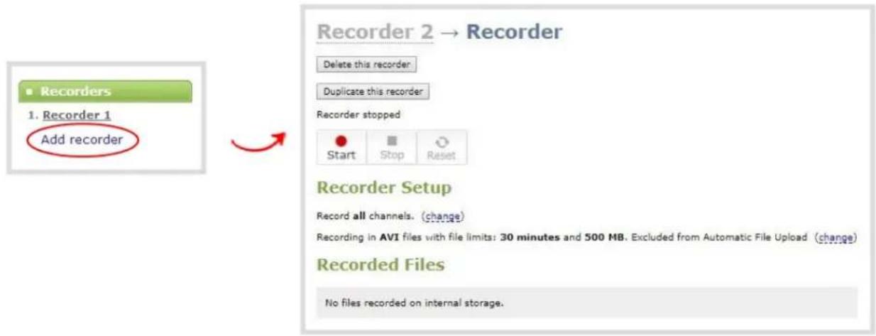
Change the channels recorded by a recorder
By default when you create a new recorder, it records all the channels configured on the system. If new channels are added, they are automatically added to the recorder.
If you wish to record a subset of channels to a single multi-track file, you can edit the channels recorded by a recorder.
To change the channels recorded by a recorder:
- Login to the Admin panel as admin. See Connect to the Admin panel.
- Select the desired recorder link from the Recorders section; the recorder configuration page opens.
- Click change next to the list of what is currently being recorded.

-
If the all channels box is selected, click it to deselect it; the other check boxes are enabled.
-
Click the check boxes for the desired channels.

Channels with no active video source are displayed in italics. You can include these channels in your channel selections for the recorder.
- Click Apply; the changes are reflected in the recorder configuration page.
Recorder Setup
Record channel(s): Auto A, HDMI-A. (change)
Recording in AVI files with file limits: 30 minutes and 500 MB (change)
Record with a recorder (using the admin panel)
Recorders can be stopped and started via the configuration page, the ability to Record channels and recorders (using One Touch control), and through Epiphan Live, and Multiple recorders and channel recordings can occur concurrently. This page gives instructions for controlling Recorders via the Admin panel.
The number of channels being recorded is displayed below the recording stop/start buttons. To configure the channels being recorded, see Change the channels recorded by a recorder.
To start and stop recorder:
-
Login to the Admin panel as admin or operator. See Connect to the Admin panel.
-
Click the name of the desired recorder; the recorder configuration page appears.
- To start recording:
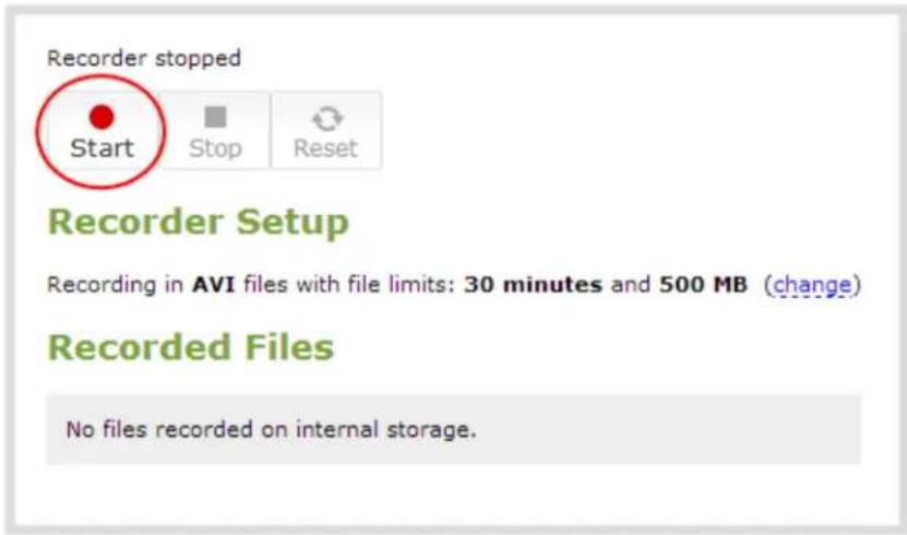
a. Click the Start button; the recording starts and a timer indicates how long it has been recording.
b. You may browse away from the page without affecting the recording. When the page refreshes, the recorder number is displayed in red to indicate recording is underway.
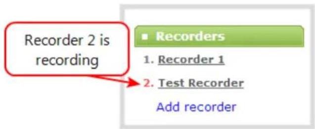
c. The system continues to record this recorder (and any concurrent recordings) until it is stopped. If the system runs out of storage space, the oldest recorded file is deleted to make room for the new recording. The recording is broken into multiple files as defined by the recorder configuration.
- To stop recording:

a. Click the Stop button on the given recorder's configuration page. The recorder number changes to black next time the Admin panel is refreshed (by clicking a link or refreshing the page).
Record a recorder (using One Touch control)
Pearl-2's "One Touch" recording/streaming control allows you to control your recording and streaming across any number of specified channels and recorders simultaneously with the touch of a button. See One Touch streaming and recording control for more information.
To control recording using One Touch control:
- Configure your desired channels and/or recorders for One Touch control in the admin panel (all channels are enabled for One Touch recording by default) (see Specify channels and recorders for One Touch recording).
- Touch the One Touch control icon in the lower portion of the touch screen to display the One Touch control screen. Note that you can customize how and when the One Touch control screen is displayed in Pearl-2's admin panel (see Customize how One Touch control is displayed.)


If the gear icon is not visible on the touch screen, tap the screen once to activate the control buttons. If the system settings button is still not visible, it is disabled in the system's touch screen configuration. See Configure the touch screen to enable system information.
- In the One Touch control screen, simply press Start to begin recording. For more information on understanding the visual elements in the One Touch control screen, see Understand and use One Touch control.

flowchart
graph LR
    A["Start\nRecording 0/6\nStreaming 0/0"] --> B["Stop\nRecording 6/6\nStreaming 0/0"]
- To stop recording, press Stop.
Record a recorder (using Epiphan Live)
You can record a recorder in Epiphan Live using the button(s) located in the Recorders section of the Dashboard interface. Note that the Recorders section only appears if at least one recorder has been added via the Admin panel (see Add a recorder for more information).
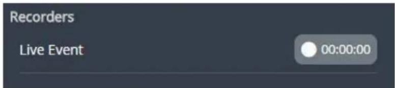
When a recorder is not being recorded, the recording button is gray in color and its timer is set to 00:00:00. To start recording a recorder, simply click the corresponding recording button.

When clicked, the recording button turns red. The timer contained within the button also begins to count upward. Click the button a second time to stop the recording.
See Epiphan Live to learn more about the Epiphan Live control interface.
Rename a recorder
To rename a recorder:
- Login to the Admin panel as admin. See Connect to the Admin panel.
- Select the desired recorder link from the Recorders section; the recorder configuration page opens.
- Click the recorder name to make it editable.

- Highlight the old name and press backspace or delete to delete it.
- Type the new name for the channel.
- Press Enter to save the change; the new name is reflected in the Admin panel.

You must press Enter to save the recorder name change.
Duplicate a recorder
You can duplicate any recorder you've created. All settings in the recorder you duplicate are recreated.
To duplicate a recorder:
- Login to the Admin panel as admin. See Connect to the Admin panel.
- Select the desired recorder link from the Recorders section; the recorder configuration page opens.

- Click the Duplicate this recorder button at the top of the page. The duplicate recorder is created and assigned the next recorder number in your list of recorders.
Delete a recorder
When you no longer need a recorder, you can delete it.

Deleting a recorder deletes all the recorded files for the recorder. Be sure you have a copy of any important recorded files.
To delete a recorder:
- Login to the Admin panel as admin. See Connect to the Admin panel.
- Select the desired recorder link from the Recorders section; the recorder configuration page opens.

-
Click the Delete this recorder button at the top of the page; a confirmation dialog reminds you that deleting the recorder will delete all recorded files.
-
Click OK on the confirmation dialog; the recorder is removed from the list and all its related files are deleted from the system.
Recorded files
Recordings you make of channels or with recorders are stored on the system's internal hard drive. Pearl-2 has a finite amount of available hard drive storage space. Though it is enough space to hold a lot of recordings, it will eventually run out of space if recordings are added but never removed. When this happens, the system deletes the oldest recorded files to make room for new recordings.
You can use a variety of methods to automatically transfer files from the system to local network storage. Alternatively you can manually select individual recordings to transfer or delete.
This section discusses the following manual file management topics.
• View list of recorded files
• Download recorded files manually
- Concatenate files
• Extract tracks from a recording
- Rename recorded files
- Delete recorded files manually
For information on automatic file transfers, see File and recording transfer.
View list of recorded files
Recordings for Pearl-2 are stored for each channel and each recorder separately. To view all the recordings stored, follow the procedures below for all channels and all recorders you have configured.
To view the recordings for a channels or recorders:
- Login to the Admin panel as admin or operator. See Connect to the Admin panel.
- To view files recorded for a channel:
a. Select a channel from the Channels section; the channel menu expands.
b. Select the Recording link for your channel; the Recording page appears.
- To view files recoded for a recorder:
a. Select the recorder from the Recorders section; the recorder page appears.
- If there are no files:
a. A message indicates there are no recorded files (for this channel).
Recorded Files
No files recorded on internal storage.
5. Otherwise:
a. All files for this channel are listed, sorted by date.
Files that are part of the same recording session are listed one after another. Three dots appear between files of different recording sessions. The file currently being recorded (if applicable) is shown at the top of the list. It cannot be modified or downloaded until it has finished recording.
b. You may also manage the list of recordings in Epiphan Live, using the Your Recordings section.
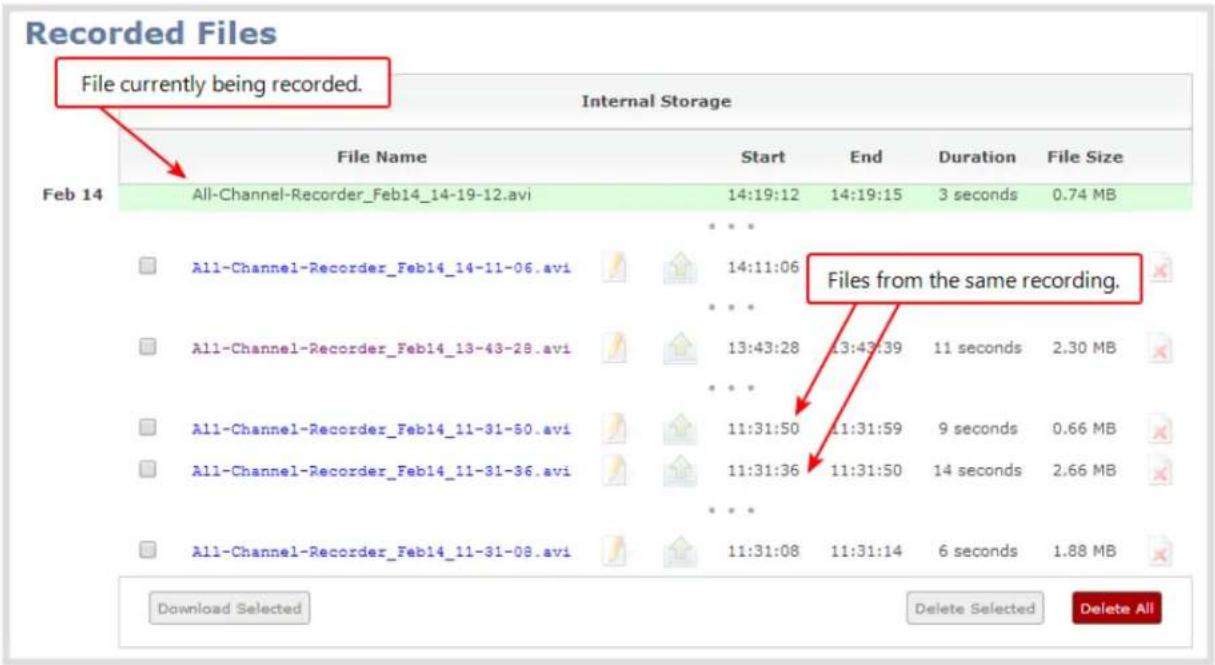
Download recorded files manually
Recordings can be manually downloaded from the Admin panel. You should consider deleting them from internal storage after you complete the download. See Delete recorded files manually, below.
This procedure explains how to download files to your admin computer. See File and recording transfer for information on transferring files to a USB drive connected to the system.
To download recordings to your admin computer:
- Login to the Admin panel as admin or operator. See Connect to the Admin panel.
- Find the recordings by channel or by recorder. See View list of recorded files.
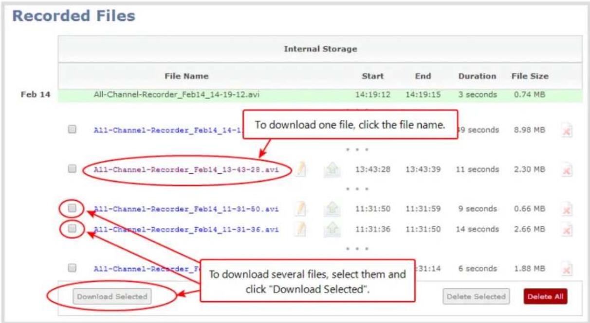
- To download an individual file:
a. Click the name of a recording file to download it.
- To download multiple files:
a. Select the check box next to the recordings you wish to download from this channel or recorder.
b. Click Download Selected to download a zip file containing the selected recordings.
Concatenate files
After recording files on Pearl-2, you may wish to combine two or more files through concatenation. The most common reason for this is that the maximum recording time was reached, and cut a single recording into two files. In this case, the best solution is to use the third-party ffmpeg tool to combine the files.
Use ffmpeg (download online if necessary) to concatenate files:
-
Download the files that you need from Pearl-2 and make sure you have the right paths and file names. For instance, "C:\Users\Technical Writer\downloads\Auto_A_Oct28_12-24-13.avi"
-
Use the command "ffmpeg -i" to specify the input file. Using the file we downloaded above, the full line will look like this: ffmpeg -i C:\Users\Technical Writer\downloads\Auto_A_Oct28_12-24-13.avi
- After specifying the first file, use the same process for the file you wish to combine it with. Note that you can repeat this process for as many files as you wish to concatenate. After specifying the second file, the full line will now look like this: ffmpeg -i C:\Users\Technical Writer\downloads\Auto_A_Oct28_12-24-13.avi -i C:\Users\Technical Writer\downloads\Auto_A_Oct28_12-24-14.avi
- Finally, use the "-c copy" command to specify the output file. After the command, type in the location, file name and file extension that you want for the concatenated file. The full line will now look like this:
ffmpeg -i C:\Users\Technical Writer\downloads\Auto_A_Oct28_12-24-13.avi -i C:\Users\Technical Writer\downloads\Auto_A_Oct28_12-24-14.avi -c copy C:\Users\Technical Writer\Desktop\Concatenated_File.avi
- After completing the process, you will be able to access your new file in the location you specified. The file will move straight from the first video into the second without pause.

As mentioned, you can use this process for any number of files, but note that the more files that are included, the higher the likelihood that there is some audio desynchronization between the clips.
Extract tracks from a recording
Recorders combine multiple channels and audio sources together in a single multi-track file. If desired, you can create a copy of a recording with only select tracks. This feature is supported for .AVI, .MP4 and .MOV recordings only (MPEG-TS does not support track extraction).

Specific track versions of recorded files are not included in any automatic file transfers and need to be downloaded manually by clicking the extracted track filename. See Download recorded files manually.
You should make sure there's enough storage space for the extracted files before you start this procedure. To check how much internal storage space is available on Pearl-2, see Storage disk maintenance.
To create a duplicate recording file with only select tracks:
- Login to the Admin panel as admin or operator. See Connect to the Admin panel.
- Select the recorder from the Recorders section; the recorder page appears.
- Find the file you want to duplicate and click the up arrow icon next to it; a list of tracks appears.

- Select the track(s) you want to extract.

Tip: To deselect all tracks, click the check box for the top track, then hold SHIFT and click the check box for the bottom track.
- Click Extract tracks; a duplicate of the recording is made with only the selected tracks.
Recorded Files
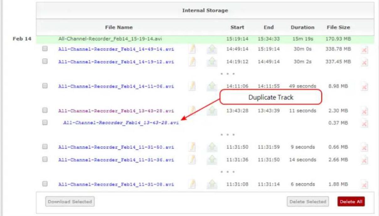

Only one duplicate recording is saved per recording file. If you create a second duplicate recording, it will overwrite the previous copy. Download the file with your extracted tracks to preserve it.
Rename recorded files
Recording files are named based on the filename prefix specified during configuration. If needed, you can rename them to something more descriptive.
You can also change the default naming mechanism. See Configure recording file size and type for more details about setting filename prefixes.
To rename recordings:
- Login to the Admin panel as admin. See Connect to the Admin panel.
- Find the recordings by channel or by recorder. See View list of recorded files.
- Select the pencil and paper icon next to the filename you wish to change.

- Type the new file name and press enter when finished.

The Admin panel keeps track of the filename extension (i.e. .avi) so you do not need to include it when renaming the file.
Delete recorded files manually
Recordings can be manually deleted via the Admin panel. You can delete one file at a time, select multiple files for a given recorder or channel and delete those, or you can delete all recordings for a channel or recorder.
If you want to delete all the files on the system, follow this procedure for each channel and recorder listed in the Admin panel.
To delete recordings:
- Login to the Admin panel as admin or operator. See Connect to the Admin panel.
- Find the recordings by channel or by recorder. See View list of recorded files.
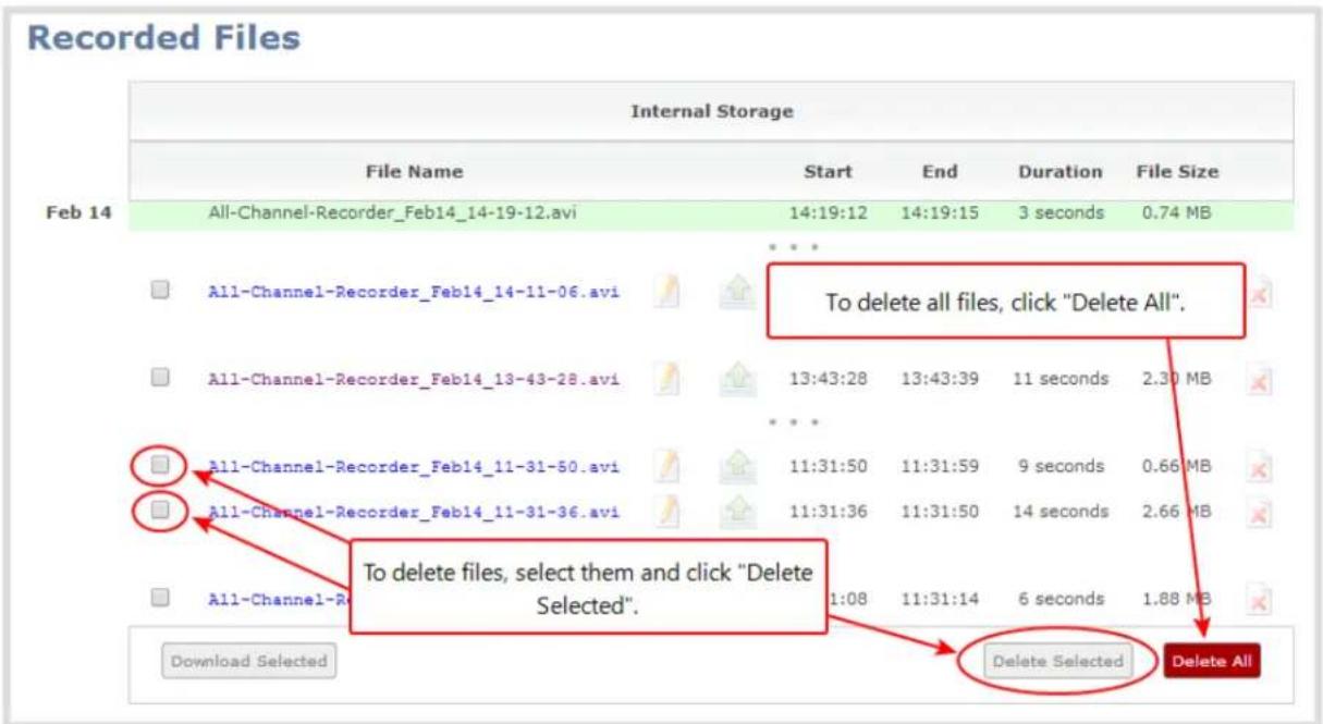
- To delete an individual file:
a. Click the X icon to the right of a file entry to request deletion; a confirmation dialog appears. b. Click OK on the confirmation dialog.
- To delete multiple files for the current channel or recorder:
a. Select the check box next to the recordings you wish to delete from this channel or recorder. b. Click Delete Selected; a confirmation dialog appears. c. Click OK on the confirmation dialog.

The list may not update immediately. You can refresh the list by reloading the Recording page (for channels) or the recorder settings page (for recorders).
- To delete all files for the current channel or recorder:
a. Click Delete All; a confirmation dialog appears. b. Click OK on the confirmation dialog.

The list may not update immediately. You can refresh the list by reloading the Recording page (for channels) or the recorder settings page (for recorders).
File and recording transfer
Your Pearl-2 can be configured to automatically upload recordings from local storage to a network storage location or an attached USB drive.
We call this process Automatic File Upload or AFU for short.
This section discusses the following generic automatic upload topics:
• Automatic file upload (AFU) overview
- Choose files to include in AFU
- Enable AFU and set parameters
And the following specific configurations based on the location of upload:
• AFU to an FTP server
- AFU using RSync
- AFU using CIFS
- AFU using SCP
• AFU to a secure FTP server
• AFU to Amazon Web Server (AWS)
• AFU to a WebDav server
• AFU or copy to USB
- Automatic
- As a one-time copy
- Manually
Lastly, this section describes how to view file upload logs and manage the AFU queue:
• View the AFU log
• View AFU status (via Pearl-2's touch screen)
- Manage the AFU queue
Automatic file upload (AFU) overview
Pearl-2 can automatically upload recorded files from channels and recorders to an accessible off-system storage location.
Automatic file upload is not enabled by default. You must enable this feature for each channel or recorder that you want included in automatic file transfers. A log file of all file transfers is created that you can view anytime from the Admin panel.
The following types of off-system storage are supported for AFU:
- FTP
- RSync
• CIFS - SCP
• SFTP
• Amazon Web Server (AWS) - WebDav
- USB Drive.

Only one type of AFU can be used for all file transfers from the same channel or recorder.
After you enable AFU, you can set the file transfer to happen after a set amount of time or after the file completes recording.
Additional settings are available to help you manage your AFU recordings and avoid file name collisions at the AFU server side. You can:
- Automatically create a folder for your recorded files using the channel or recorder name.
- Save recordings to a folder that's labeled using the Pearl-2 serial number.
Files are automatically uploaded only once. New recordings created during later sessions do not overwrite files that were previously uploaded. A new file is uploaded.
If the connection is lost during the transfer, the transfer automatically restarts when the connection is reestablished.
If recorded files are selected for upload while the AFU is at maximum upload capacity or when the AFU is unavailable, they are added to an upload queue. Files and their relevant information are displayed in a list and are uploaded when the upload capacity becomes available.
Choose files to include in AFU
When configuring automatic file upload (AFU) you need to tell the system which channels and recorders you want included in the upload schedule.
When you log into the system and attempt to configure your desired type of AFU you see the following warning in the Automatic File Upload configuration page if no channels or recorders are configured to be part of AFU.

For each channel or recorder you want to add to your AFU schedule:
- Login to the Admin panel as admin. See Connect to the Admin panel.
- For a channel recording:
a. Click the desired channel; the channel menu expands.
b. Select the Recording link for the channel; the Recording page opens.
- For a recorder:
a. Click the desired recorder link from the Recorders section; the recorder configuration page opens.
- Select the change link under Recorder Setup; the recorder setup section expands. (The setup page looks slightly different for Recorders, but the options are the same.)
Recorder Setup
Recording in AVI files with file limits: 30 minutes and 500 MB. Excluded from Automatic File Upload (change)
Recorder Setup
Time limit: 30 minutes ▼
Size limit: 500 MB ▼
File type: AVI
Filename prefix:
Automatic file upload
Share via UPnP
Single touch control
Apply
- Check the Automatic file upload check box.
- Click Apply; the Recording page is refreshed and the new settings are reflected.
Recorder Setup
Recording in AVI files with file limits: 30 minutes and 500 MB. Included into Automatic File Upload (change)
Now that AFU is enabled for your desired set of files, enable AFU and configure your desired mechanism.
Enable AFU and set parameters
After configuring the channels and recorders to include in your AFU schedule, you must enable AFU and configure the frequency of transfers.

Files saved before you complete automatic file upload configuration are not part of the automatic upload. Manual file transfer is required for these files. See Download recorded files manually.
To set up the frequency of automatic file uploads:
- Login to the Admin panel as admin. See Connect to the Admin panel.
- Select Automatic File Upload from the Configuration section; the Automatic File Upload configuration page opens.
Automatic File Upload
Enabled for: Live Program

Enable Automatic File Upload
Protocol:
External USB drive ▼
How often:
On file rotation ▼
Remote path:

Remove after upload

Mark file as downloaded

Create a subfolder for each channel

Create a subfolder for device
Show log of automatic file upload
External USB drive
Apply

If your screen does not indicate that AFU is enabled for at least one channel or recorder, return to Choose files to include in AFU
-
Select the Enable Automatic File Upload checkbox.
-
Specify how often automatic updates should happen.
The first transfer occurs after the specified amount of time expires, or after the current file completes recording (i.e. if the value is set to every hour and five videos are saved the first hour, those five videos are uploaded after the first hour, and one hour later the videos saved in the second hour are uploaded).
The following table describes the available options.
Table 45 Automatic File Upload Interval Options
| Name Description | |
| On file rotation | The system uploads each file after it stops recording it. You can control file size and length to determine when files are done recording. You can also use the reset button to close the current file and open a new one. See Configure recording file size and type. |
| Every hour The system uploads completed recordings every hour. | |
| Every 6 hours The system uploads completed recordings every six hours. | |
| Every 12 hours The system uploads completed recordings every 12 hours. | |
| Every 24 hours The system uploads completed recordings every 24 hours. | |
- (Optional) Indicate the remote path, if desired. If no path is specified, the files are copied to the root folder of the destination file system.

If AFU to your server fails, check the server configuration and permissions.
-
(Optional) Check Remove after upload to have the files deleted from local storage when upload completes.
-
(Optional) Check Mark file as downloaded to have the color of the file link in the recording list change to show the files are downloaded. This only applies if the files are not deleted after upload is complete.
-
(Optional) Check Create a subfolder for each channel to save the downloaded files in to a folder. Use either the channel or recorder name.
-
(Optional) Check Create a subfolder for device to save the downloaded files in to a folder using the serial number of Pearl-2.
-
Select the protocol or destination for upload. The following table describes the options.
Table 46 Automatic File Upload Protocol Options
| Name Description | |
| FTP Client The system uploads to an FTP server. | |
| RSync Client The system uploads to a network location using RSync to copy the file. | |
| CIFS Client | The system uploads to a network location using CIFS (also known as SMB or samba) such as a shared folder on a Windows machine. |
| SCP Client | The system performs secure copy (SCP) to a remote server. Authentication is done either by password or uploaded SSH key. |
| SFTP Client | The system uploads to a secure FTP server. Authentication is done either by password or uploaded SSH key. |
| AWS S3 Client | The system uploads to a bucket on Amazon Web Server (AWS) Simple Storage Solution (S3). |
| WebDav Client The system uploads to a remote WebDav server. | |
| External USB Drive The system uploads to a USB drive connected directly to the system. | |
- Follow one of the procedures below to configure your selected protocol or transfer type.
• AFU to an FTP server
- AFU using RSync
- AFU using CIFS
- AFU using SCP
• AFU to a secure FTP server
• AFU to Amazon Web Server (AWS)
• AFU to a WebDav server
- AFU or copy to USB
AFU to an FTP server
This procedure assumes you have completed the steps in Enable AFU and set parameters and wish to continue with configuration of upload to an FTP Server.
To configure upload to an FTP server:
- Select FTP Client from the protocol drop down list in the Automatic File Upload configuration page; the lower half of the page reflects the selection.

- Specify the target Server address. If your system is configured with DHCP or has a valid DNS configuration (see Configure DHCP), you can use the server's fully qualified domain name instead of the IP address.
- Specify the Server Port used for the target FTP server. The standard port is 21.
- Enter the FTP account username in the Login field.
- Enter the FTP account password in the Password field; the characters are masked with dots.
- Select Use temp file to name files with a temporary filename extension (.part) on the server until upload is complete.
- Click Apply; if there are any problems the system notifies you with a message: One or more parameter values are not valid and those were not applied!
The following table describes the options applicable to configuring upload to an FTP server.
Table 47 FTP Automatic Upload Configuration Options
| Name Description / Options | |
| Server address | The IP address (or fully qualified domain name) of the FTP server. |
| Server port The port used by the target FTP server. Standard port is 21. | |
| Login Username for the FTP server. | |
| Password Password for the FTP user. | |
| Use temp file | Causes files to be named with .part extension on the server during active upload. Whenthe upload completes, the file is renamed to the appropriate extension (.mov, .mp4 or .avi). |
AFU using RSync
This procedure assumes you have completed the steps in Enable AFU and set parameters and wish to continue with configuration of upload using RSync.
To configure upload using RSync:
- Select RSync Client from the protocol drop down list in the Automatic File Upload configuration page; the lower half of the page reflects the selection.
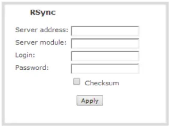
- Specify the target Server address. If your system is configured with DHCP or has a valid DNS configuration (see Configure DHCP), you can use the server's fully qualified domain name instead of the IP address.
- Specify the Server module. This is the name of the shared folder on the server. If needed, request this value from your network administrator.
- Specify a username for the RSync Server in the Login field. The user must have write permissions for the module.
- Specify the password for the user in the Password field; the value is masked by dots.
-
If desired, select the Checksum check box to add a checksum validation to the transfer between the system and the recipient server.
-
Click Apply; if there are any problems the system notifies you with a message: One or more parameter values are not valid and those were not applied!
The following table describes the options applicable to configuring upload to an RSync server.
Table 48 RSync Automatic File Upload Configuration Options
| Name Description / Options | |
| Server address | The IP address (or fully qualified domain name) of the RSync server. |
| Server module | The name of the shared folder on the RSync server. |
| Login Username | for the RSync server. |
| Password Password for the RSync user. | |
| Checksum | Select to enable checksum checking during file transfer. This increases the time taken to transfer, but also increases reliability of the transfer. |
AFU using CIFS
This procedure assumes you have completed the steps in Enable AFU and set parameters and wish to continue with configuration of upload using CIFS (also known as SMB or samba).
To configure upload using CIFS:
- Select CIFS Client from the protocol drop down list in the Automatic File Upload configuration page; the lower half of the page reflects the selection.
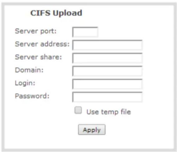
- Specify the target Server address. If your system is configured with DHCP or has a valid DNS configuration (see Configure DHCP), you can use the server's fully qualified domain name instead of the IP address.
- Enter the target Server port, if you have configured the server to use something non-standard. Leave this value blank to use the default port.
- Specify the Server share. This is the CIFS share name or the name of the shared folder on the server. If needed, request this value from the network administrator.
- If the system is in a different domain than the server or if it is part of Active Directory, enter the Domain name of the CIFS server.
- Specify a username for the CIFS Server in the Login field. The user must have write permissions for the share folder.
- Specify the password for the user in the Password field; the value is masked by dots.
- Select Use temp file to name files with a temporary filename extension (.part) on the server until upload is complete.
- Click Apply; if there are any problems the system notifies you with a message: One or more parameter values are not valid and those were not applied!
The following table describes the options applicable to configuring upload to a CIFS server.
Table 49 CIFS Automatic File Upload Configuration Options
| Name Description / Options | |
| Server Port | The CIFS server port. Leave blank to use the default port, or enter the port used for your CIFS server. |
| Server address | The IP address (or fully qualified domain name) of the CIFS server. |
| Server share The name of the shared folder on the CIFS server. | |
| Domain | The CIFS server's Windows domain or Work Group name . Needed if the server is part of Active Directory or a Domain Controller. |
| Login Username for the CIFS server. | |
| Password Password for the CIFS user. | |
| Use temp file | Causes files to be named with .part extension on the server during active upload. When the upload completes, the file is renamed to the appropriate extension (.mov, .mp4, .ts or .avi). |
AFU using SCP
This procedure assumes you have completed the steps in Enable AFU and set parameters and wish to continue with configuration of upload via secure copy (SCP).
To configure upload via SCP:
- Select SCP Client from the protocol drop down list in the Automatic File Upload configuration page; the lower half of the page reflects the selection.
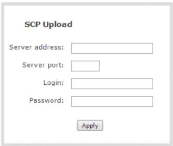
- Specify the target Server address. If your system is configured with DHCP or has a valid DNS configuration (see Configure DHCP), you can use the server's fully qualified domain name instead of the IP address.
- Specify the Server Port used for the destination SCP server. The standard port is 22.
- Enter the SCP account username in the Login field.
- Enter the SCP account password in the Password field; the characters are masked with dots. (Alternatively you can choose to use a private key instead of a password for authentication.)

For secure copy you can upload an SSH identity for your Pearl-2. This key must be trusted by the destination server. Details for generating the key and setting up this trust are beyond the scope of this document.
- If desired, scroll down to the section labelled SSH identity for SCP and SFTP clients.
![SSH identity for SCP and SFTP clients No identity uploaded. Upload your private key. Key passwords are not supported. Upload a private key file: (must not have a password) Choose File No file chosen Upload Test your key: (user@server[:port]) Test Remove identity: Remove](/content/2026/06/1365921/images/ff32f466b2ae34f07b4d41fd7e2796575e407252fc75964994074aa365d3d6e7.jpg)
- If no identity is uploaded, or to upload a new identity (overwrites the old identity):
a. Click Choose File; a file selection dialog opens.
b. Select the private key file from your hard drive and click Open.

The system accepts RSA keys for SSH-1; DSA, ECDSA, EC25519 and RSA for SSH-2. Keys must be in OpenSSH format.
c. Click Upload to upload the file.
-
Use the Test your key field to test your uploaded key against the secure server, if desired.
-
Click Apply; if there are any problems the system notifies you with a message: One or more parameter values are not valid and those were not applied!
The following table describes the options applicable to configuring upload using SCP.
Table 50 SCP Automatic Upload Configuration Options
| Name Description / Options | |
| Server address | The IP address (or fully qualified domain name) of the destination server. |
| Server port The | SCP port used by the target server. Standard port is 22. |
| Login Username for the SCP server. | |
| Password Password for the SCP user. | |
AFU to a secure FTP server
This procedure assumes you have completed the steps in Enable AFU and set parameters and wish to continue with configuration of upload to a secure FTP Server (SFTP).
To configure upload to a secure FTP (SFTP) server:
- Select SFTP Client from the protocol drop down list in the Automatic File Upload configuration page; the lower half of the page reflects the selection.

- Specify the target Server address. If your system is configured with DHCP or has a valid DNS configuration (see Configure DHCP), you can use the server's fully qualified domain name instead of the IP address.
- Specify the Server Port used for the target SFTP server. The standard port is 22.
- Enter the SFTP account username in the Login field.
- Enter the SFTP account password in the Password field; the characters are masked with dots. (Alternatively you can choose to use a private key instead of a password for authentication.)
- Select Use temp file to name files with a temporary filename extension (.part) on the server until upload is complete.

For secure file transfer you can upload an SSH identity for your Pearl-2. This key must be trusted by the destination server. Details for generating the key and setting up this trust are beyond the scope of this document.
- If desired, scroll down to the section labelled SSH identity for SCP and SFTP clients.
![SSH identity for SCP and SFTP clients No identity uploaded. Upload your private key. Key passwords are not supported. Upload a private key file: (must not have a password) Choose File No file chosen Upload Test your key: (user@server[:port]) Test Remove identity: Remove](/content/2026/06/1365921/images/8bb8c2302b92ef20fe19fa1f5912d5ca7d8dcef0801f9f241f55dc4a60322009.jpg)
- If no identity is uploaded, or to upload a new identity (overwrites the old identity):
a. Click Choose File; a file selection dialog opens.
b. Select the private key file from your hard drive and click Open.

The system accepts RSA keys for SSH-1; DSA, ECDSA, EC25519 and RSA for SSH-2. Keys must be in OpenSSH format.
c. Click Upload to upload the file.
-
Use the Test your key field to test your uploaded key against the secure server, if desired.
-
Click Apply; if there are any problems the system notifies you with a message: One or more parameter values are not valid and those were not applied!
The following table describes the options applicable to configuring upload to a SFTP server.
Table 51 SFTP Automatic Upload Configuration Options
| Name Description / Options | |
| Server address | The IP address (or fully qualified domain name) of the SFTP server. |
| Server port The port used by the target SFTP server. Standard port is 22. | |
| Login Username for the SFTP server. | |
| Password Password for the SFTP user. | |
| Use temp file | Causes files to be named with .part extension on the server during active upload. When the upload completes, the file is renamed to the appropriate extension (.mov, .mp4 or .avi). |
AFU to Amazon Web Server (AWS)
This procedure assumes you have completed the steps in Enable AFU and set parameters before you configure uploading files automatically to a bucket on Amazon Simple Storage Solution (S3).
You must have read and write privileges for your AWS account to setup AFU to upload to an AWS S3 location.
To configure upload to AWS S3:
- Select AWS S3 Client from the protocol drop down list in the Automatic File Upload configuration page; the lower half of the page reflects the selection.

- Specify the AWS Region Code and the data storage Bucket where you want to upload the file.
- Enter your AWS Access Key Id and Secret Access Key to authenticate access to the AWS S3 data storage bucket.
- In the Session Token field, enter the temporary token you got from the AWS Security Token Service (STS).
- Click Apply.
The following table describes the options for uploading to AWS S3.
Table 52 AWS Automatic Upload Configuration Options
| Name Description / Options | |
| AWS Region Code | The geographical region of the AWS server that contains the bucket you want to upload to, e.g. us-east-2. |
| Bucket | The id of the data storage container you created in Amazon S3 for the recorded live streaming files. |
| Access Key Id | The Access Key Id is part of your access key for your AWS account, i.e. GAKSOSIFDONN2EXAMPLE. |
| Secret Access Key | The secret access key is part of your access key for your AWS account, i.e.bHaprXUenFEMI/K6MANVG/cPxDfiBYEXAMPLEKEY. |
| Session Token | The temporary security token provided by the AWS Security Token Service (STS) that allows access to your AWS account for authorized users. |
AFU to a WebDav server
This procedure assumes you have completed the steps in Enable AFU and set parameters and wish to continue with configuration of upload to a WebDay Server.
To configure upload to a WebDav server:
- Select WebDav Client from the protocol drop down list in the Automatic File Upload configuration page; the lower half of the page reflects the selection.

- Specify the target Server address. If your system is configured with DHCP or has a valid DNS configuration (see Configure DHCP), you can use the server's fully qualified domain name instead of the IP address.
- Specify the Server Port used for the target WebDav server. The standard port is 21.
- Enter the FTP account username in the Login field.
- Enter the FTP account password in the Password field; the characters are masked with dots.
- Select Enable HTTPS if you need a secure HTTPS link to the WebDav server.
- Select Use temp file to name files with a temporary filename extension (.part) on the server until upload is complete.
- Click Apply; if there are any problems the system notifies you with a message: One or more parameter values are not valid and those were not applied!
The following table describes the options applicable to configuring upload to a WebDav server.
Table 53 WebDav Automatic Upload Configuration Options
| Name Description / Options | |
| Server address | The IP address (or fully qualified domain name) of the FTP server. |
| Server port The port used by the target WebDav server. Standard port is 21. | |
| Login Username for the WebDav server. | |
| Password Password for the WebDav user. | |
| Enable HTTPS Select if you need to use a secured HTTPS link to the WebDav server. | |
| Use temp file | Causes files to be named with .part extension on the server during active upload. When the upload completes, the file is renamed to the appropriate extension (.mov, .mp4 or .avi). |
AFU or copy to USB
The system is equipped with USB 3.0 ports that can be used to copy files from internal storage to external USB flash drives or hard drives. An example use of this feature is to provide speakers with a copy of their presentation before they leave the presentation venue.
The external drive must be formatted with one of the following file systems:
- FAT16
- FAT32
• XFS
- EXT2
- EXT3
- EXT4
• NTFS
File transfer to a USB drive occurs in one of the following ways. This section describes the procedures.
- AFU to a USB drive
• One-time copy/move of all recorded files to USB drive
• Manually copy recorded files to USB drive
• View available USB storage space
• Safely eject the USB drive

Only one copy or move to USB operation is permitted at a time, even though the UI may appear to let you start a second one. Please wait until the first is complete before starting a new operation.
AFU to a USB drive
This procedure assumes you have completed the steps in Enable AFU and set parameters and wish to continue with configuration of upload to a USB drive.
To configure automatic upload to a USB drive:
(USB ports are available on both the back and the front of Pearl-2.)
- Insert the properly formatted USB drive into one of the system's USB ports. (USB ports are available on both the back and the front of Pearl-2.)
- Select External USB Drive from the protocol drop down list in the Automatic File Upload configuration page; the lower half of the page reflects the selection.
External USB drive
Apply
- If your Automatic File Upload setting conflicts with your new USB drive setting, a message is displayed.

- Click the fix link.
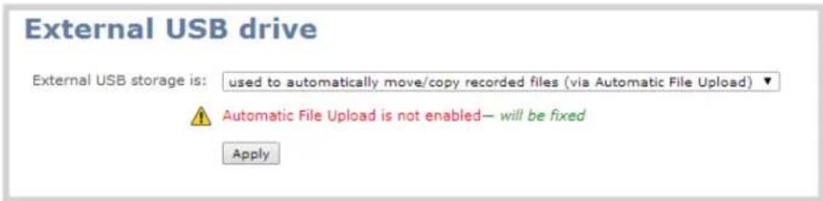

Using the fix link disables any other type of automatic file upload you have configured. When you are done with USB uploads, return to the Automatic File Upload configuration page and re-configure FTP, RSYNC, or CIFS.

After clicking the fix link, the text changes to "will be fixed", however changes are saved only after clicking Apply.
-
Select Create a subfolder for each channel to have recordings organized by channel.
-
Click Apply; the changes are saved.
One-time copy/move of all recorded files to USB drive
When configured to make a one-time copy of files, the system will automatically begin to copy files to an inserted USB drive, starting with the newest recording. Files will continue to copy until all are copied, the specified maximum number of files is copied, or the target drive runs out of storage space.

The file currently being recorded (if any) cannot be transferred until recording is completed.
This procedure is separate from automatic file upload and does not need any pre-configuration in the automatic file upload page.

Ideally only USB drives with visible activity indicators should be used.
To configure a one-time copy of all recorded files to a USB drive:
- Login to the Admin panel as admin. See Connect to the Admin panel.
- Select the External USB Drive link in the Configuration section; the External USB Drive configuration page is displayed.
- Select used for one-time move/copy of the recorded files (upon insertion) from the drop down list.
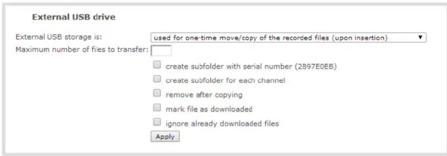
- Select the appropriate check boxes based on the descriptions provided in the following table. If your USB drive does not have activity indicators it is suggested you select either remove after copying or mark file as downloaded so you know when the transfer is complete.
Table 54 One-Time Transfer/Copy to External USB Drive Options
| Name Description | |
| create subfolder with serial number () | If checked, the transfer process creates a sub-folder with the system's serial number on the USB drive. This is useful if you are using the same drive to collect recordings from multiple systems and want to know which system they came from. |
| create subfolder for each channel | If checked, the transfer process creates a sub-folder for each channel and recorder (within the subfolder for the serial number, if that option is also selected). Files are copied to their respective folders. |
| remove after copying | If checked, the file(s) are removed after being copied to the USB drive. Checking this box makes the transfer a move instead of a copy. |
| mark file as downloaded | If checked, the files that are downloaded are marked with a downloaded icon when viewing file lists. This has no effect if remove after copying is checked. |
| ignore already downloaded files | If checked, files that were previously downloaded or marked as downloaded are not included in subsequent downloads. |
- Click Apply; the changes are saved.

If a conflict is reported regarding the Automatic file upload, go to the Automatic File Upload configuration page and disable automatic file upload or switch it to a non-USB based upload type. Repeat the steps above.
- Insert the properly formatted USB drive into one of the system's USB ports; the drive is recognized and the transfer begins. If the drive has an activity indicator light, it flashes during the transfer.
- When the activity light stops flashing, remove the USB drive.
- If your USB drive does not have activity indicators:
a. Check the Recording list for each channel and the Recorded Files list for each recorder to verify if there are files that have yet to be copied.
b. Safely eject the USB drive when you are satisfied all files have been copied, or if you see the USB drive is out of storage space (View available USB storage space).
Manually copy recorded files to USB drive
You can manually copy recorder files to a USB drive connected to Pearl-2.
This procedure is separate from automatic file upload and does not need any pre-configuration in the automatic file upload page.
To manually copy recorded files to a USB drive:
- Login to the Admin panel as admin. See Connect to the Admin panel.
- Select the External USB Drive link in the Configuration section; the External USB Drive configuration page is displayed.
- Select used to manually move/copy selected files via the Admin panel from the drop down list.

- Click Apply; the changes are saved.

If a conflict is reported regarding the Automatic file upload, go to the Automatic File Upload configuration page and disable automatic file upload or switch it to a non-USB based upload type. Repeat the steps above.
- Insert your USB drive in an available USB port on the system. (It is recommended you only use one USB drive at a time.) (USB ports are available on both the back and the front of Pearl-2.)
- To download files for a specific channel:
a. Select the desired channel from the Channels list
b. Click the Files Archive link for the selected Channel
- To download files for a recorder:
a. Select the desired recorder from the Recorders list
- Select the check box next to the files you wish to download. In the example below the topmost file is still recording and cannot be downloaded.
Recorded Files
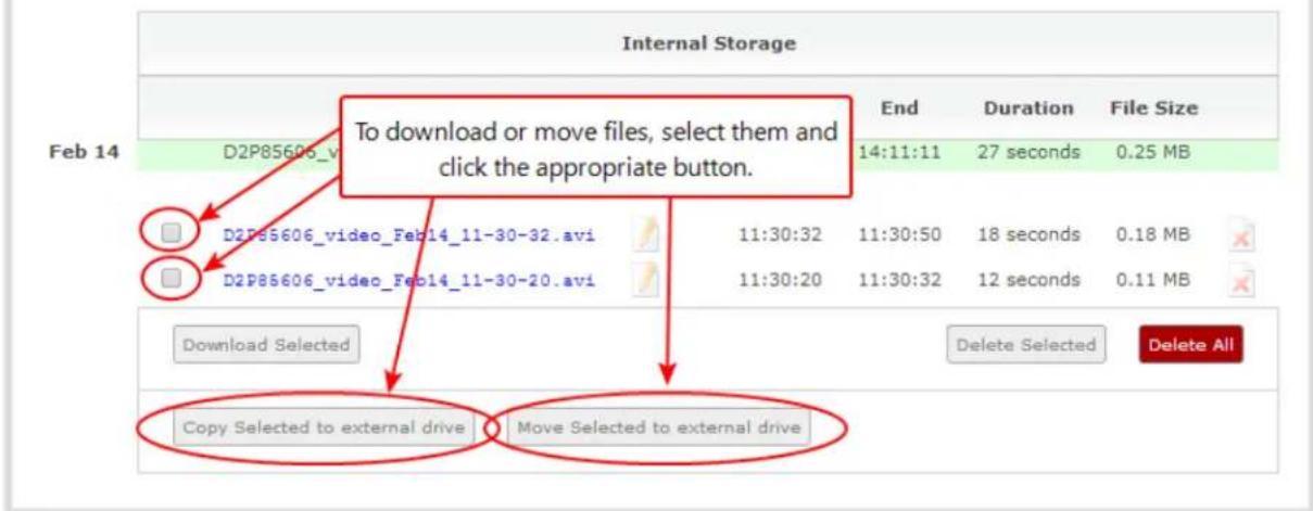
- To copy the files to the USB drive:
a. Click Copy Selected to external drive
- To move the files to the USB drive (i.e. erase the files after the copy)
a. Click Move Selected to external drive
- Repeat the steps to select a channel or recorder and copy or move files to the external drive until you
have copied all the files you wish.
- Follow the steps to Safely eject the USB drive.
View available USB storage space
When you insert a USB drive in an available port of Pearl-2 and select an External USB Drive action other than ignored (i.e. manual copy, automatic copy, etc), the total and free space are calculated and displayed in the Admin panel.
To see the available USB storage space:
- Login to the Admin panel as admin. See Connect to the Admin panel.
- Insert your USB drive in an available USB port on the system. (It is recommended you only use one USB drive at a time.) (USB ports are available on both the back and the front of Pearl-2.)
- Scroll to the bottom of the Admin panel page; external USB storage is displayed under internal storage space.

bar_stacked
| Category | Value (GB) | Percentage (%) | | :--- | :--- | :--- | | Internal storage | 14.41 | 8 | | External storage | 7.64 | 98 | | eject | - | - |Safely eject the USB drive
When you have completed work with the USB drive you can safely eject it by using the link at the bottom of the Admin panel page.
To safely eject the USB drive:
- Login to the Admin panel as admin. See Connect to the Admin panel.
- Scroll to the bottom of the Admin panel page; click the eject link below external storage space.
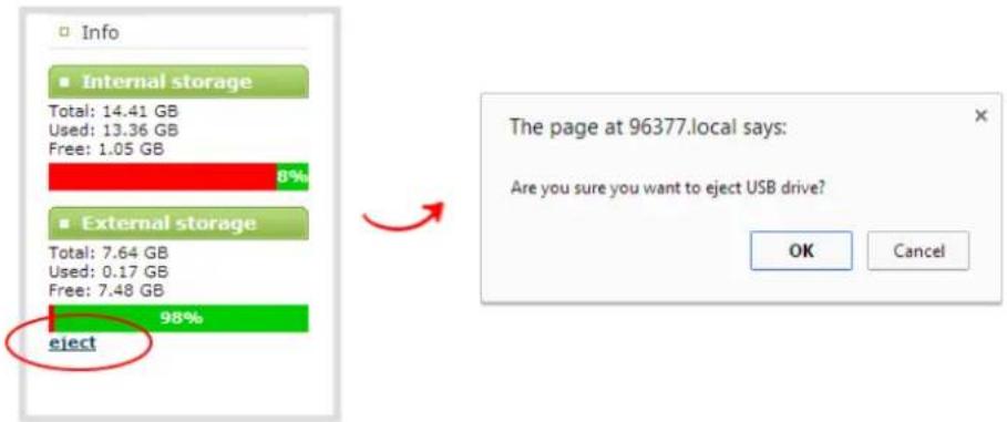
- When prompted, click OK to confirm that you want to eject the USB drive.
- Disconnect the USB drive from the system.
View the AFU log
A log is kept of automatic file uploads.
To view the log:
- Login to the Admin panel as admin. See Connect to the Admin panel.
- Select Automatic File Upload from the Configuration section; the Automatic File Upload configuration page opens.

- Click the Show log of automatic file upload link; the log page opens. Note the page is blank if there are no logs present.
- Click the browser's back button when you are done.
View AFU status
You can view basic Automatic File Upload (AFU) information from your Pearl-2's touch screen.
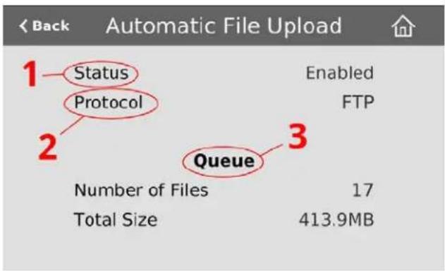
See File and recording transfer to learn how to configure AFU settings in the Admin panel.
Table 55 AFU status touch screen components
| Label | Name | Description |
| 1 Status | Indicates the AFU status:EnabledDisabledWaiting – files are in queue to be transmitted for upload according to specified time interval – within the next 6, 12 or 24 hours. (See Enable AFU and set parameters)Error – an error has occurred with the AFU | |
| 2 Protocol | Provides the configured AFU protocol:FTPRSYNCCIFSSCPSFTPAWS S3 ClientWebDavExternal USB drive | |
| 3 Queue | Displays the number of files currently in the AFU queue and the total file size. |
To access the Automatic File Upload status in the touch screen:
- Touch the system settings button (the gear icon) in the lower right corner of the screen.


If the gear icon is not visible on the touch screen, tap the screen once to activate the control buttons. If the system settings button is still not visible, it is disabled in the system's touch screen configuration. See Configure the touch screen to enable system information.
- Touch the arrow icon in the lower-right corner of the screen to naviget to the second Settings page.
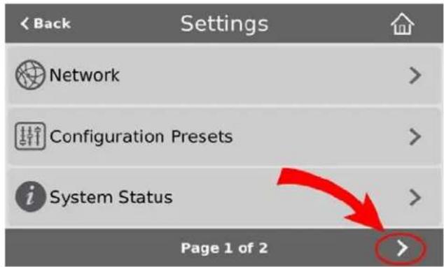
- Touch Automatic File Upload to display the AFU Status page.

To close the system information screen, touch Back (in the upper-left corner of the screen) to return to the System Settings view, or the Home icon to return to the channel view.
Manage the AFU queue
The AFU queue displays a list of recording files waiting to be uploaded. Individual file details can be viewed using the Admin panel.
Access the AFU queue
Accessing the AFU queue allows you to view the list of files queued for upload using the Admin panel.
To access the AFU queue:
- Login to the Admin panel as admin. See Connect to the Admin panel.
- From the Admin panel, click Automatic File Upload; if there are files to be uploaded, they are displayed under the Upload Queue header.
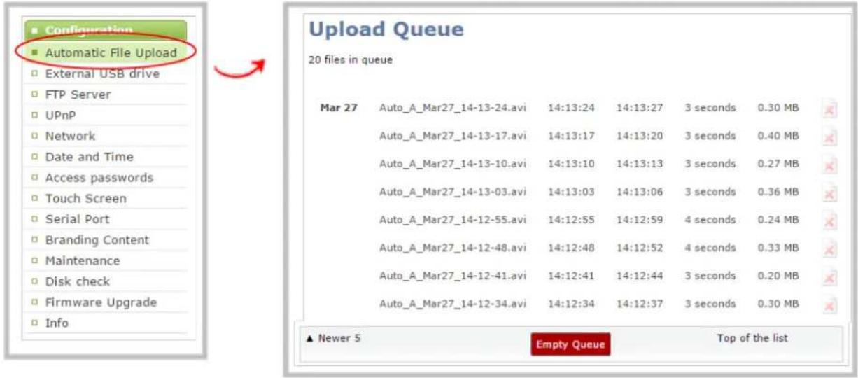
View content in the AFU queue
There are several buttons in the Admin panel that allow you the ability to control how you see your queued content.
To control how you view content in the AFU queue:
- Navigate to the bottom of the upload queue list and manipulate the list view using the Newer 5 and Top of the List buttons.


The upload queue can display only 15 files at one time. Additional content is still stored and is viewed in increments of five files using the Newer 5 button.
Delete content in the AFU queue
Files can be deleted from the upload queue, either individually or as a group.
To remove content from the upload queue:
- Navigate to the bottom of the upload queue and click Empty Queue to delete the entire upload queue, or click the red 'X' icon at the end of each row to remove files individually.

Note that there is no confirmation prompt after pressing Empty Queue. Once pressed, the queue is immediately deleted with no way to restore the queued files.
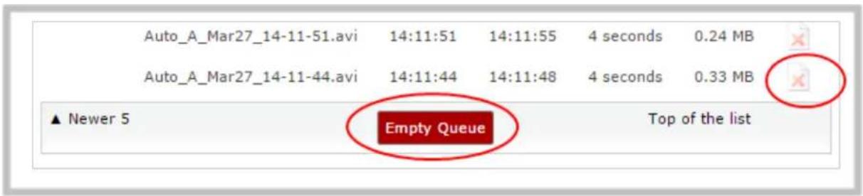
Local FTP server
Pearl-2 can act as an FTP server, allowing you to manually or automatically connect to the system and download recordings. Depending on configuration of the FTP server, you may also be able to remotely delete files after download, maximizing available system storage.

When using an FTP server to download a file, it is possible to start the download while that file is still in the process of being recorded. This results in an incomplete file. To avoid this, check the status of the file in the Admin panel before beginning the download process.
This section discusses the following FTP Server topics.
- Configure the local FTP server
• Using the local FTP server
Configure the local FTP server
To configure your sysetem's local FTP server:
- Login to the Admin panel as admin. See Connect to the Admin panel.
- Select the FTP Server link in the Configuration menu; the FTP Server configuration page opens.
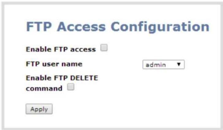
- To enable the FTP server:
a. Select the Enable FTP access check box.
b. Select a user from the FTP user name drop down.

The ftp password is the regular access password for the selected user. See User administration for details on user names and passwords.
c. Click Apply.
- To allow the FTP user to delete files:
a. Select the Enable FTP DELETE command check box.
b. Click Apply.

Any currently logged in ftp users must log out and back in again to have access to the command.
- To disable the FTP server:
a. De-select the Enable FTP access check box.
b. Click Apply.
- To disable file deletion by FTP:
a. De-select the Enable FTP DELETE command check box.
b. Click Apply.

Any currently logged in users will continue to have access to the delete command until they log out and log in again.
The following table summarizes the options for configuring the local FTP server.
Table 56 FTP Server Configuration Options
| Name Description / Options | |
| Enable FTP access | The check box controls whether or not the system acts as an FTP server. By default this is disabled. |
| FTP user name | Select one of the system users: admin, operator, or viewer. The ftp password will be the access password for the selected user. By default the admin user is selected. |
| Enable FTP DELETE command | Controls whether or not FTP users can delete files. By default file deletion is not permitted. |
Using the local FTP server
Once you have configured a local FTP server, you can use the tool of your choice to download files from the system.
The system stores files in a folder structure with a folder for each channel and a folder for each recorder. Channel folders are labeled video
To get started you will need:
- The IP address of your system (found in the Network configuration menu)
- An FTP tool
- The username and password for your FTP user (See Configure the local FTP server)
In the example below, the IP address of Pearl-2 is 192.168.1.210, the username is admin, there is no password, and the Windows command line ftp utility is used.
To connect to the FTP server:
- Open a command window on Windows (alternatively open a terminal window on Linux/Mac, or open your FTP utility of choice).
- Establish an ftp connection using the command: ftp 192.168.1.210.
- Provide the username: admin (provide the username of your FTP user).
- Provide the password: (provide the correct password for your FTP user); the connection is opened.
- Use the dir command to see the file structure.

- Use dir or your tool's GUI to look in each folder for recordings.
- Use get or your tool's transfer mechanism to transfer files to your computer.
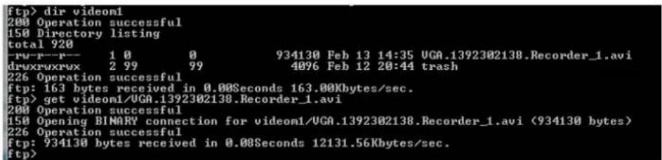
- If enabled in the FTP configuration page, delete the file after downloading it by issuing the delete command, or using your tool's delete mechanism.

If the delete command is not enabled, attempting to delete a file will result in an Unknown Command error.
PART 5: Maintenance
This section covers topics that will keep your Pearl-2 running smoothly. It also covers the Epiphan Live interface and ways to configure and operate your system using third party tools via HTTP or RS-232.
Specific topics covered are:
• Power down and system restart
- Perform factory reset
- Firmware upgrade
- Support
• Storage disk maintenance
• Third party integration
Power down and system restart
This section covers the following topics:
- Restarting the device via the Admin panel
- Shutting down the device via the Admin panel
- Shutting down the device manually
Restarting the device via the Admin panel
Pearl-2's Admin panel allows you to reboot the system.
To restart the system:
- Login to the Admin panel as admin. See Connect to the Admin panel.
- Select the Maintenance link in the Configuration menu; the maintenance page opens.
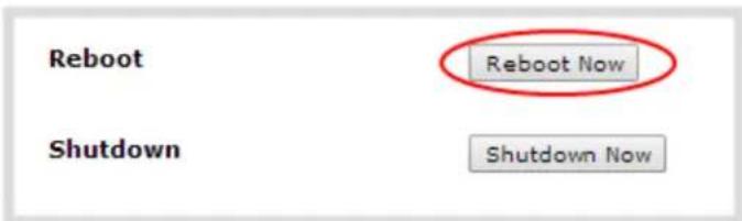
- Click the Reboot Now button; a confirmation dialog appears.
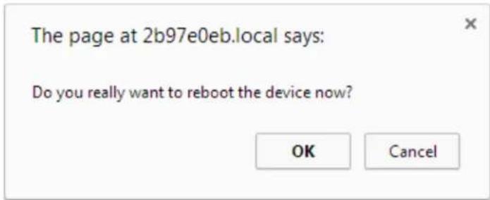
- Click OK.
Shutting down the device via the Admin panel
The Pearl-2 Admin panel allows you to shut down the system.
To shut down the system:
- Login to the Admin panel as admin. See Connect to the Admin panel.
- Select the Maintenance link in the Configuration menu; the maintenance page opens.
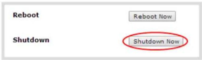
- Click the Shutdown Now button; a confirmation dialog appears.

- Click OK.
Shutting down the device manually
You can manually shut down the Pearl-2 via the button physically located on the system.
Note: The power button for Pearl-2 is found on the front.
To shut down the system manually:
- Double-click (two successive fast presses and releases) the system power button to initiate a safe power down; the system shuts down.

If the system is unresponsive, press and hold the power button for 4 seconds to force an immediate power down.
Save and restore device configuration
The previously used backup and restore procedure is replaced by configuration presets, which are the perfect way to backup all or any set of your configuration items for future import back to the same system or another. See Configuration presets for more details.
Perform factory reset
If you've been testing with your Pearl-2 and are ready to reset it back to factory settings, you can do this through the Admin panel.
This section covers the following topics:
- Restore factory configuration via the Admin panel
Restore factory configuration via the Admin panel
The Admin panel allows you to restore the factory configuration to return your Pearl-2 back to the original settings it had when you purchased it.

Restoring the factory settings erases everything on the system. This includes all your source settings, channels, configuration presets, network settings and all saved files.
Consider using the factory default configuration preset if you want to preserve files. See Configuration presets.
Only proceed if you know this is what you want to do.
To restore the factory configuration via the Admin panel:
- Login to the Admin panel as admin. See Connect to the Admin panel.
- Select the Maintenance link in the Configuration menu; the maintenance page opens.
Factory reset
Factory reset

WARNING: All recordings, branding files, configuration presets, channels and recorders will be removed!
- Click the Reset button next to Factory Reset; a warning dialog appears asking you to confirm this destructive action.

- Click OK on the warning dialog; the system resets to factory defaults and reboots.
- Wait for the system to reboot and begin re-configuration.
Firmware upgrade
Epiphan will from time-to-time issue an updated firmware revision to bring new features to your Pearl-2. To take advantage of these new features, you will need to install the new firmware on the system.
This section covers the following topics:
• Check for firmware updates
• Install firmware
Check for firmware updates
When you register your product with Epiphan you are given a choice to be notified by email of firmware updates for your system. If you selected this choice, you will be notified of updates applicable to Pearl-2.
If your Pearl-2 has internet access, you can check for updates directly by following the procedure below.
The system will also automatically check for firmware updates if the Maintenance page option Enable connection to maintenance server is checked.

This is the preferred method of checking for firmware updates. The built-in firmware update mechanism checks for updates that match your specific product and hardware revision.
To check for new firmware:
- Login to the Admin panel as admin. See Connect to the Admin panel.
- Select the Firmware Upgrade link in the Configuration menu; the firmware upgrade page opens.
- Click the check for updates link next to your current firmware version; the system connects to Epiphan servers to look for updates.
- If an update is found a red box appears in the top left side of the Admin panel with a link to download and install the firmware.

- Follow the steps below to download and install the firmware.
Install firmware
When you've received a new firmware file from Epiphan's support team, schedule a time where you can update the firmware without negatively impacting viewers or file recordings.

It is good practice to take a backup of your current configuration before applying a firmware update. In the rare case that you wish to downgrade the firmware, you will be able to apply this configuration backup and restore your previous state. See Create a configuration preset.
There are two ways to install new firmware: from the download link via the Admin panel, or from a file provided by Epiphan.

Installing new firmware takes a few minutes. Broadcasting and recording are not available until the upgrade is complete.
While the firmware update is applied, the touch screen displays a firmware update in-progress notice and no other interaction is possible. Do not interrupt power to the system during the firmware upgrade.
Install firmware directly from the Admin panel:
If your Pearl-2 has internet access, the easiest method of installing new firmware is to use the download link provided when you check for new firmware.
To download new firmware directly:
- Login to the Admin panel as admin. See Connect to the Admin panel.
- Save a copy of the current system configuration, if desired. See Configuration presets.
- Select the Firmware Upgrade link in the Configuration menu; the firmware upgrade page opens.
- Click the check for updates link next to your current firmware version; the system connects to Epiphan servers to look for updates.
- Click download from the red box that appears at the top left of the Admin panel; the firmware is downloaded and immediately starts to install and the firmware update box changes to have a cancel button.
- The touch screen, if enabled, also displays a notice that the firmware update is in progress.
Firmware Update

In Progress...

Do not interrupt power to the system during the firmware upgrade.
- When the firmware update is complete, the message lets you know it is going to reboot.
Firmware update
Rebooting...
- Wait for the system to restart. Depending on the upgrade, a disk rebuild may be required, causing the restart process to take much longer than usual.
- Connect to the Admin panel using your preferred connection mechanism. See Connect to the Admin panel.
- Login as admin.
- Select the Firmware Upgrade link in the Configuration menu; the firmware upgrade page opens.
- Verify that the firmware version is the expected new version.
Although unexpected, it is possible the firmware update fails. In this case, the touch screen reports the failure. Please collect system information such as device serial number and, if known, the previous firmware version along with the new firmware version and contact info@epiphan.com
Firmware Update Error

E-Mail: info@epiphan.com
Install firmware from a file
Before getting started, ensure you have the firmware file accessible from your admin computer.
To install new firmware from a file:
- Login to the Admin panel as admin. See Connect to the Admin panel.
- Save a copy of the current system configuration, if desired. See Configuration presets.
- Select the Firmware Upgrade link in the Configuration menu; the firmware upgrade page opens.
- Note the current firmware version listed.
- Click the Choose File button next to Select firmware upgrade file; a file selection box opens.
- Select the firmware upgrade file from your local computer.
- Click Apply; the file is uploaded. The system unpacks and verifies the file. If the file is valid, the upgrade begins.
- The touch screen, if enabled, also displays a notice that the firmware update is in progress.
Firmware Update

In Progress...

Do not interrupt power to the system during the firmware upgrade.
- Wait for the system to restart.
- Connect to the Admin panel using your preferred connection mechanism. See Connect to the Admin panel.
- Login as admin.
- Select the Firmware Upgrade link in the Configuration menu; the firmware upgrade page opens.
- Verify that the firmware version is the expected new version.
Although unexpected, it is possible the firmware update fails. In this case, the touch screen reports the failure. Please collect system information such as device serial number and, if known, the previous firmware version along with the new firmware version and contact info@epiphan.com
Firmware Update Error

E-Mail: info@epiphan.com
Support
Epiphan provides a complimentary one-year support plan with your purchase (starting one year from the original product shipment date) as well as two extended support plans, SupportPlan and SupportPlan+. Both plans add two more years to extend the support to three years from original product shipment date.

To contact Epiphan support:
• Email: support@epiphan.com
- Online chat: www.epiphan.com/support (Monday to Friday between 9am and 5pm Eastern)
• Call: 1-877-599-6581 / 613-599-6581
From time to time, Epiphan support may ask you for logs from your system. Follow the instructions in this section to download the log files for support.
- Download logs and "allinfo"
Pearl-2 also supports remote troubleshooting by Epiphan's support team. This service is only available to systems covered by SupportPlan+.
Remote support allows Epiphan to assist in troubleshooting issues you experience with the system and can also assist with resetting lost admin passwords. No private information is sent to the Epiphan maintenance server.
By default, all systems are setup with remote support configuration enabled.
This section describes procedures for the following topics:
- Configure remote support
- Disable remote support

Remote support is only provided for systems covered by SupportPlan+. For more information about our service plans, see www.epiphan.com/supportplan.
Download logs and "allinfo"
If requested by Epiphan support, you can download the logs files and/or "allinfo" data from your system. These files help our support team troubleshoot problems.
To download the logs and allinfo file:
-
Login to the Admin panel as admin. See Connect to the Admin panel.
-
Select the Maintenance link in the Configuration menu; the maintenance page opens.
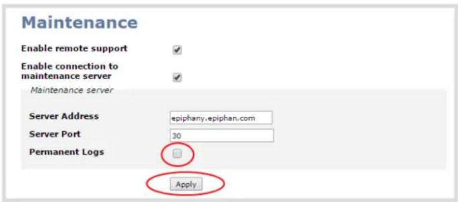
- Select the Permanent Logs check box.
- Click Apply; the page updates to let you know the changes were applied.
- Select the Maintenance link again; the maintenance page opens.

- Click Download permanent logs; a zip file containing system logs begins to download.
- From your browser, run the allinfo script; a file is saved to your computer.
http://
- Share the log files and allinfo results with Epiphan support.
Configure remote support
Remote support is configured by default to connect to the Epiphan maintenance server with the domain name epiphany.epiphan.com. The system must be able to resolve this domain name to connect to the server and permit remote support. Remote support uses ports 22 and 30, therefore this port must be available for communication. If your system is protected from the Internet by a firewall, speak to your network administrator to configure the firewall appropriately.

Remote support is available from Epiphan only if your device is covered by SupportPlan+.
To configure remote support:
- Login to the Admin panel as admin. See Connect to the Admin panel.
- Select the Maintenance link in the Configuration menu; the maintenance page opens.

- Click Enable remote support if the check box is not selected. This setting controls incoming links from Epiphan.
-
Click Enable connection to maintenance server if the check box is not selected. This setting configures outgoing links to Epiphan.
-
Ensure the server address is epiphany.epiphan.com, unless Epiphan support directs you to change it.
-
Ensure the port is 30, unless Epiphan support directs you to change it.
-
Click Apply.
-
Test that the system can access the maintenance server:
a. Select the Network link under Configuration.
b. Type epiphany.epiphan.com Network Diagnostics box.
c. Click ping.
d. Ensure the result shows an IP address for epiphany.epiphan.com and report any packet loss to Epiphan support.
-
If the system cannot reach the maintenance server, check the network settings (see Configure DHCP) to ensure DHCP is selected or a DNS server is listed and try again. Consult with your network administrator if problems persist.
-
If the system reaches the maintenance server, ensure your firewall, if you have one, has port 30 open for the system.
-
Confirm with Epiphan support that they are able to access your Pearl-2 for remote troubleshooting.
Disable remote support
By default, remote support is on. If you want to turn it off, you may use the following procedure.

Disabling remote support for Pearl-2 removes the ability for Epiphan to reset a lost admin password. If you forget the admin password and remote support feature is off, you will need to return the system to Epiphan for reprogramming.
To disable remote support:
- Login to the Admin panel as admin. See Connect to the Admin panel.
- Select the Maintenance link in the Configuration menu; the maintenance page opens.
- Click Enable remote support check box to deselect it. This prevents incoming links from Epiphan.
- Click Enable connection to maintenance server to deselect it. This prevents outgoing links to Epiphan.
- Click Apply.
Storage disk maintenance
Your Pearl-2 is equipped with a solid-state storage drive for storage of recordings. Occasionally, maintenance is required for these disks. This section describes procedures for the following topics:
- Check disk storage space
- Check disk storage space via the touch screen
- Schedule disk check
- Perform disk check
Check disk storage space
Pearl-2 has a finite amount of storage. By default, Pearl-2 has a 512 GB SSD. This storage space holds a lot of recordings, but it can get full. It's a good idea to monitor your current disk usage.
If available storage is low, consider removing some unneeded recordings or setting up an automatic file transfer with deletion after transfer. See Recorded files and File and recording transfer.

Disk space can also be checked via the Epiphan Live control interface. See Configuring Dashboard panels for visual confidence monitoring for more information.
To check disk storage space:
- Login to the Admin panel as admin or operator. See Connect to the Admin panel.
- Check the Internal Storage section at the bottom of the menu column. The bar will be mostly green if there is lots of space left, or mostly red if storage space is nearly full.
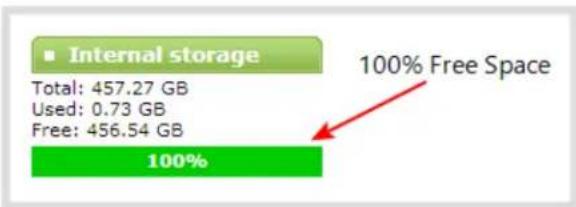
bar_stacked
| Category | Value (%) | |---|---| | Internal storage | 100% Free Space | | Total | 457.27 GB | | Used | 0.73 GB | | Free | 456.54 GB |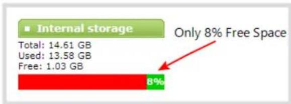
bar
| Category | Value (GB) | |---|---| | Internal storage | 14.61 | | Used | 13.58 | | Free | 1.03 | Only 8% Free Space- If available storage is low, take action to remove files as discussed in Recorded files and File and recording transfer.
Check disk storage space via the touch screen
Pearl-2's touch screen can show you the system's disk space on the system information screen.
To show system information on the touch screen:
-
If the system information button does not appear on the screen, tap the screen once to turn on the control buttons.
-
If the system information button is still not visible, it is disabled in the system's touch screen configuration. See Configure the touch screen to enable system information.
-
Touch the system information button (i) on the screen

To close the system information screen:
- Touch anywhere on the screen to return to the previous screen.
Schedule disk check
A disk maintenance schedule is used to check the system storage drives for errors. Two values are supplied, one to specify the number of system restarts that should occur before disk check, and the second to specify the number of months before performing a disk check. The disk check happens based on whichever event occurs first.
For example, let's say the restart setting is set to 50 and the months setting is set to 6. If six months pass and less than 50 restarts happened, a disk check will occur on the next restart. However if you do 50 restarts in one month, the disk check will happen after the fiftieth restart.

Disk check occurs during start up and can cause a lengthy delay in starting up the system.
To set the disk check schedule:
-
Login to the Admin panel as admin. See Connect to the Admin panel.
-
Select the Disk Check link in the Configuration menu; the disk maintenance page opens.
-
Set the number of restarts to occur before the next check. Set to 0 if you don't want to force a disk check after a specific number of restarts.
-
Set the number of months to pass before the next check. Set to 0 if you don't want to force a disk check after a specific number of months.
-
Click Save.
Perform disk check
A disk maintenance schedule is used to periodically check the system storage drives for errors. If you prefer, you can run the disk check manually at a time that is convenient for you.
Running the disk check manually resets the timers for the scheduled disk check (i.e. next check won't happen automatically until either the number of restarts or months passes).

If the system is recording when you start a disk check, it will stop recording and resume after the check is complete. Frames presented during the disk check are not part of any recording.
To start a manual disk check:
-
Login to the Admin panel as admin. See Connect to the Admin panel.
-
Select the Disk Check link in the Configuration menu; the disk maintenance page opens.
-
Click the Check Now button; a new page opens showing you the progress of the disk check.

Do not interrupt power to the system during the disk check.
← → C 192.168.1.164/admin/fsck.cgi
Disk check in progress
DO NOT navigate away from this page, interrupt or power down until the disk check is completed.
Started disk check id 31500 on Mon Feb 3 15:52:20 EST 2014 e2fock 1.41.4 (27-Jan-2009) Pass 1: Checking inodes, blocks, and sizes |==================== | 96.0%
- When the disk check is complete, the main page returns and a summary is shown.
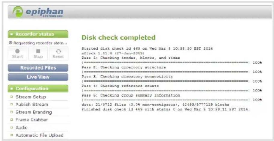
- If any unrecoverable errors are detected, contact Epiphan support.
Third party integration
Pearl-2 has a comprehensive set of APIs to allow integration with third party tools.
You can use either the HTTP or RS-232 commands to configure your system exactly how you need it. For example you can start and stop recordings, you can configure meta data on a channel, or even change a channel's frame size and encoding settings.
The following topics are covered in this section:
• Control with RS-232 / serial port
• Control with HTTP commands
- Configuration keys for third party APIs
Control with RS-232 / serial port
Pearl-2 presents an RS-232 / serial port control interface for integration with existing control room and board room equipment. This section covers the following topics:
- Connect and configure the RS-232 cable
• Control Pearl-2 with RS-232
• RS-232 / Serial port command examples
Connect and configure the RS-232 cable
To connect your control equipment to Pearl-2 you will need a standard RS-232 cable.
To connect the serial port cable:
- Attach the RS-232 cable to the control interface.
- Connect the RS-232 cable to the back of the system.
The only configuration available for the serial port is flow control. Flow control changes the rate of data transfer over the cable. Some communication settings are static and cannot be changed. The static settings are:
• Baud rate set at 19200
- Parity set to none
- Stop bits set to one
To configure serial port flow control:
- Login to the Admin panel as admin. See Connect to the Admin panel.
- Select the Serial Port link in the Configuration menu; the serial port configuration page opens.
- Select Hardware, Software, or None from the drop-down menu. Refer to the table below for a description of the options.
Table 57 Serial Port Flow Control Options
| Label Description / Options | |
| Hardware | A hardware handshake mechanism is used for flow control. This is also called RTS / CTS flow control. Select this when your control terminal requires it (see control terminal manual). |
| Software | A software handshake that uses XON/XOFF characters to control the flow of data. Select this when your control terminal requires it (see control terminal manual). |
| None | No flow control is used. Only select this if your control terminal requires it (see control terminal manual). |
4. Click Apply.
Control Pearl-2 with RS-232
You can use the null-modem cable and your control terminal software to issue commands to Pearl-2 such as when to start or stop recording, or to retrieve or set the value for various settings.

Each command sent to Pearl-2 via RS 232 must be terminated with a line feed (LF) character (ASCII code 10). Your software may need to be configured to add the line feed to each command.
Some commands require a channel or recorder name as an argument. In those commands, the channel or recorder name is separated from the command name by a period, as shown in the table. The channel name value can be either the name or the index of the recorder or channel. Use of the index is recommended.
A channel's index is found by looking at the Channels list in the Admin panel. In the screen capture below, the channel with index 1 is currently recording (it's index number is red). To address this channel via RS-232 commands, use the index 1.
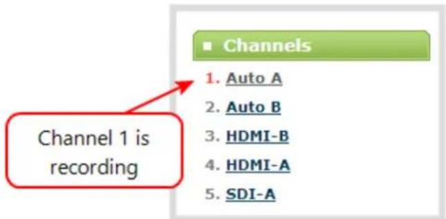
For commands requiring a recorder index, determine your recorder's index by combining the recorder's number with the prefix m. In the example below, the second recorder's index is 2. To access this recorder via RS-232 commands, use the index m2.

The table describes the RS-232 commands supported by Pearl-2.
Table 58 Supported RS-232 Commands
| Command Name Description | |
| Recording Commands | |
| START. | Starts recording for the provided channel or recorder. This can alternatively be accomplished with the following set commands:SET.<channel>.rec_enabled=onSAVECFGIf the channel is already recording, the current recording is continued. |
| START | Starts recording for all channels and recorders. There is no RS-232 command to restart recording. If recording is already active when the start command is issued, the recording continues. There is no RS-232 command to restart recording. If recording is already active when the start command is issued, the recording continues. |
| STOP. | Stops recording for the provided channel or recorder. This can alternatively be accomplished with the following set commands:SET.<channel>.rec_enabled=""SAVECFG |
| STOP. | |
| STOP Stops recording for all channels and recorders. | |
| SNAPSHOT. | Takes a snapshot image of the current channel (supported only if the channel is configured to use the Motion JPEG codec). Snapshots are saved with recording files on the system. |
| SNAPSHOT | Takes a snapshot image of all channels (supported only for channels configured to use the Motion JPEG codec). Snapshots are saved with recording files on the system. |
| Configuration Commands (seeConfiguration keys for third party APIsfor available keys) | |
| GET.<channel>.<key>GET.<recorder>.<key> | Gets the saved value of a given parameter for the specified channel or recorder. |
| SET.<channel>.<key>SET.<recorder>.<key> | Sets the value of a given parameter for the specified channel or recorder. The value is not saved until the SAVECFG command is sent. |
| SAVECFG Saves the parameters modified by the SET command. | |
| Status Commands | |
| STATUS.<channel>STATUS.<recorder> | Reports the recording status of the specified channel or recorder.Status is one of:RUNNINGSTOPPEDUNINITIALIZED |
| STATUS | Reports the recording status of each channel and recorder.Status is one of:RUNNINGSTOPPEDUNINITIALIZED |
| FREESPACE Reports the free storage space, in bytes. | |
| RECTIME.<channel>RECTIME.<recorder> | Reports the elapsed recording time in seconds for the current file on the specified channel or recorder. |
| RECTIME Reports the elapsed recording time in seconds for the current file on each channel. | |
Additionally, the system automatically reports its status changes back along the RS-232 connection using the following automatic messages:
Table 59 RS-232 Status Changed Messages
| Command Name Description | |
| STATUS. | Provides the status of the recording service for the channel as either:• RunningStoppedUninitializedThe Uninitialized status is sent when there is an internal error. Check the system for more details. |
RS-232 / Serial port command examples
The following examples demonstrate how to use some of the RS-232 commands supported by the system. The list of supported SET and GET parameters are found in Configuration keys for third party APIs.

Each command sent to Pearl-2 via RS 232 must be terminated with a line feed (LF) character (ASCII code 10). Your software may need to be configured to add the line feed to each command.
For values with spaces, enclose the value in quotation marks. For empty values, use empty quotation marks with nothing between.

You must always follow a "SET" command in RS-232 with the "SAVECFG" command. Otherwise the new configuration setting(s) will not take effect. See "SET" examples below.
- To start recording on channel 2:
START.2
- To stop recording on channel 2:
STOP.2
- To start recording on all channels and recorders:
START
- To get the value of the frame size (resolution) for channel 2:
GET.2-framesize
- To set the frame size (resolution) on channel 2, enclose the parameter in quotes to preserve the spaces:
SET.2.framessize="640 x 480"
SAVECFG
- To enable broadcasting audio on channel 2:
SET.2.audio=on
SAVECFG
- To disable broadcasting audio on channel 2:
SET.2.audio=""
SAVECFG
Control with HTTP commands
Pearl-2 has an HTTP API interface for configuration and control by a third party application or with a script that sends commands to the system as a series of URLs. This section covers the following topics:
- HTTP command syntax
- HTTP command examples
• Global variable HTTP command syntax for custom layouts
HTTP command syntax
Control of Pearl-2 by HTTP is done by sending commands to one of two URLs and specifying the target configuration item. Syntax for the get and set commands follows.
Many commands require a channel or recorder index as an argument. A channel's index is found by looking at the Channels list in the Admin panel. In the screen capture below, the channel with index 1 is currently recording (it's index number is red). To address this channel via http commands, use the index channel1.

For commands requiring a recorder index, determine your recorder's index by combining the recorder's number with the prefix channelm. In the example below, the second recorder's index is 2. To access this recorder via http commands, use the index channelm2.

To Get configuration settings:
http://<address>/admin/channel<N>/get_params.cgi?key
(or for recorders, add 'm' before the recorder number, i.e. channelm1 for recorder 1)
http://<address>/admin/channelm<N>/get_params.cgi?key
To Set configuration settings:
http://<address>/admin/channel<N>/set_params.cgi?key=value
(or for recorders, add 'm' before the recorder number, i.e. channelm1 for recorder 1)
http://<address>/admin/channelm<N>/set_params.cgi?key
Where
is the IP address of the system, channelMultiple requests at once
You can include multiple key/value pairs in a single command by separating the statements with &.
For example, the key for product name is product_name and the key for firmware version is firmware_version. To send a request for both the product name and the firmware version, use the following command:
http://<address>/admin/channel1/get_params.cgi?product_name&firmware_version
Or, to turnoff publishing (set to 0) and set the bitrate (vbitrate) to 256,000:
http://<address>/admin/channel1/set_params.cgi?publish_type=0&vbitrate=256K
Third party applications like wget
If you're using a third party application like wget to send commands to the system, always include the admin username and password when viewing or setting configuration items.
The syntax for wget commands is shown below. Specify your system's IP address, password and the key(s) or value(s) you wish to query. Note your system may require use of single quotes around the password to handle special characters such as exclamation marks.
get_param using wget:
wget --http-user=admin --http-passwd=<password> http://<address>/admin/channel<N>/get_params.cgi?<key>[&<key>]
set_param using wget:
wget --http-user=admin --http-passwd=<password> http://<address>/admin/channel<N>/set_params.cgi?<key>=<value>[&<key>=<value>]
HTTP command examples
Some configuration of Pearl-2 can be done by non-interactive http commands. The following examples demonstrate how to use wget to exercise some of the HTTP commands supported by the system.

For values with spaces, encode space as %20. i.e.: set_params.cgi?framesize=640%20x%20480
The examples assume a system IP address of 192.30.23.45 and admin password pass123.
- To get the type of stream being published and frame size for channel 1:
wget --http-user=admin --http-passwd=pass123 http://192.30.23.45/admin/channel1/get_params.cgi?publish_type&framesize
- To set the publish stream type to RTMP Push (6) and at the title "System Stream" for channel 2:
wget --http-user=admin --http-passwd=pass123 http://192.30.23.45/admin/channel2/set_params.cgi?publish_type=6&title=System%20Stream
- To start recording on channel 2:
wget --http-user=admin --http-passwd=pass123 http://192.30.23.45/admin/channel2/set_params.cgi?rec_enabled=on
- To stop recording on channel 2:
wget --http-user=admin --http-passwd=pass123 http://192.30.23.45/admin/channel2/set_params.cgi?rec_enabled=""
5. To start recording on recorder 2:
wget --http-user=admin --http-passwd=pass123 http://192.30.23.45/admin/channelm2/set_params.cgi?rec_enabled=on
Global variable HTTP command syntax for custom layouts
Your Pearl-2 can create global variables via HTTP for use specifically with custom layout as responsive text overlay elements. See Add a text overlay (custom channel) for more information on adding a global variable into a custom layout.
Important considerations for global custom layout variables
• Each system variable must have its own unique name
- System variable names and variable values are case sensitive
- Each variable name must start with a letter or underscore sign and is followed by any combination of letters, digits and underscore characters [A-Za-z_0-9]{0,32} to a limit of 32 total characters (note that saving an empty string to a variable will clear the variable value)
• There is a limit of 1024 total unique system variables per Pearl-2 system
- System variables can be used in text labels across any number of channels
- System variable commands can be issued at a frequency of 5 per second, and up to 6 variables may be set in a single command (for example, variables "gpsvar1", "gpsvar2" and "gpsvar3" can be updated in a single command, five times per second). After issuing a set command, all channels using the specified variable(s) are updated. The frequency of commands issued is not influenced by the number of channels on your Pearl-2 system.
- System variables are considered volatile data and are erased when your Pearl-2 system reboots
Set variables – syntax and example
A set command saves a value to a variable, where
is the IP address of the Pearl-2, name is the unique name for each variable, and value is the text/character content stored in each variable.You can set multiple variables at the same time by separating each variable with an "&" (as shown within the square brackets in the syntax below).
To "set" variables, use the following syntax:
http://
/admin/set_variables.cgi?name1=value1[&nameN=valueN]For values with spaces, encode space as %20. (i.e.: set_variables.cgi?name1=640%20x%20480)
To erase a previously set variable, simply set the variable's name with an empty space.
Example: "http://192.168.0.129/admin/set_variables.cgi?gpsvar1=N103%2068201%20W765%2029712&gpsvar2=S490%2018731%20E756%2019890&gpsvar3=N123%2046891%20W345%2065431&gpsvar4=S767%2033410%20E770%2004513"
sets:
"gpsvar1" to "N103 68201 W765 29712"
"gpsvar2" to "S490 18731 E756 19890"
"gpsvar3" to "N123 46891 W345 65431"
"gpsvar4" to "S767 33410 E770 04513"
Get variables – syntax and example
A get command returns the value of a variable (called name in the syntax). You can return multiple variables at the same time by separating each variable with an "&" (as shown within the square brackets in the syntax below).
To "get" a variable (or a list of specified variables), use the following syntax:
http://
/admin/get_variables.cgi?name1[&nameN]Example: "http://192.168.0.129/admin/get_variables.cgi?gpsvar1"
returns:
"gpsvar1=N103 68201 W765 29712"
To "get" a list of all variables saved to your Pearl-2, use the following syntax:
http://
/admin/get_variables.cgiExample: "http://192.168.0.129/admin/get_variables.cgi"
returns:
"gpsvar1=N103 68201 W765 29712
gpsvar2=S490 18731 E756 19890
gpsvar3=N123 46891 W345 65431
gpsvar4=S767 33410 E770 04513"
To learn how to use global variables as text overlays in custom channels, see Add a text overlay (custom channel).
Configuration keys for third party APIs
Using HTTP or RS-232, you can send commands to the system to query or configure the system. For the RS-232 and HTTP syntax see Control with RS-232 / serial port and Control with HTTP commands.

Using a "SET" command in RS-232 must always follow with the "SAVECFG" command for the new configuration setting(s) to take effect.
When setting keys to values with spaces use the following syntax.
For RS-232:
Enclose in quotes: SET.2.framesize="640 x 480"
For HTTP:
Encode each space as %20: set_params.cgi?framesize=640%20x%20480
The following sections describe the API keys supported by the system in each of these categories:
• System-level settings keys (read-only)
• System-level settings keys (read/write)
• System-level custom layout keys (read/write)
- Touch screen settings keys (read/write)
• Recording configuration keys
- HTTP server configuration keys
• IP-based access control configuration keys
• UPnP configuration keys
- Broadcast configuration keys
• Channel encoder configuration keys
• Channel layout configuration keys
• Audio configuration keys
• Stream publishing configuration keys
• RTSP Announce configuration keys (Publish type 2)
• RTP/UDP configuration keys (Publish type 3)
- MPEG-TS configuration keys (Publish types 4 and 5)
• RTMP push configuration keys (Publish type 6 and 7)
• Livestream configuration keys (Publish type 8)
- Content metadata configuration keys
The list of supported keys is also available for viewing from your system. Browse to the following URL (where
is the IP address of the system):http://<address>/admin/http_api.cgi
System-level settings keys (read-only)
The following read-only system-level setting keys are supported. The channel number can be omitted from the command when requesting the value for these keys.
Table 60 Supported Read-Only System-level Settings configuration keys
| Key Values Description | ||
| firmware_version | String, including the text FIRMWARE_VERSION=. | The system's firmware version.The value is read-only. |
| mac_address String | The system's mac address. Useful for debugging.The value is read-only. | |
| product_name String | The product's name.Useful to confirm you are communicating with the right product or for debugging purposes.The value is read-only. | |
| vendor Epiphan Video | Name of the vendor.The value is always “Epiphan Video”.The value is read-only. | |
System-level settings keys (read/write)
The following read/write system-level setting keys are supported. The channel number can be omitted from the command when requesting the value for these keys.
Table 61 Supported Read/Write System-level Settings configuration keys
| Key Values Description | ||
| frmcheck_enabled | onempty string (""") | Enables or disables automatic firmware update checking.To enable firmware update checking, set to on.To disable firmware update checking, set to an empty string (""") |
| description string | To give this system a name in the Epiphan discovery utility,specify a description string. | |
System-level custom layout keys (read/write)
The following read/write system-level custom layout keys are supported.
Table 62 Supported read/write system-level custom layout keys
| Key Values Description | ||
| name | Any combination of letters, digits and underscore characters [A-Za-z_0-9]{0,32} to a limit of 32 total characters | Each unique name key contains a variable value. Used for dynamic overlay text in custom layouts (see Control with HTTP commands and Add a text overlay (custom channel)) |
Touch screen settings keys (read/write)
The following configuration keys are supported for modifying the touch screen configuration. The channel number can be omitted from the command when requesting or setting the value for these keys.
Table 63 Supported Touch Screen Settings configuration keys
| Key Values Description | ||
| touchscreen_backlight integer( 0...255) Specify the touchscreen backlight level. | ||
| touchscreen_enabled | onempty string ("") | Enables or disables the touch screen.To enable the touch screen, set to on.To disable the touch screen, set to an empty string (""). |
| touchscreen_info | onempty string ("") | Enables or disables system information from the touch screen.To enable system info from the touch screen, set to on.To disable system info from the touch screen, set to an empty string (""). |
| touchscreen_preview | onempty string ("") | Enables or disables channel preview on the touch screen.To enable preview on the touch screen, set to on.To disable preview on the touch screen, set to an empty string (""). |
| touchscreen_recordctl | onempty string ("") | Enables or disables recording control from the touch screen.To enable recording from the touch screen, set to on.To disable recording from the touch screen, set to an empty string (""). |
| touchscreen_settings | onempty string ("") | Enables or disables settings changes from the touch screen.To enable settings changes from the touch screen, set to on.To disable settings changes from the touch screen, set to an empty string (""). |
| touchscreen_timeout integer | Specify the time in seconds before the touchscreen times out.For no timeout, use 0. | |
Recording configuration keys
The following recording settings are supported. When using,, specify the channel or recorder you wish to configure.
Table 64 Supported Recording configuration keys
| Key Values Description | ||
| rec_enabled | onempty string ("") | Enables or disables recording.To enable recording, set to on.To disable recording, set to an empty string (""). |
| rec_format | avimovmp4mp4fts | Specifies the format of the saved file. (mp4 is used for the progressive mp4 file format, mp4f for fragmented) |
| rec_prefix string S | Specifies a prefix for the | recorded filenames. |
| rec_sizelimit integer | Specifies the file size | limit, in kilobytes (kB). |
| rec_timelimit | string (no quotes)hh:mm:ss | Specifies the time limit before a new recording file is created.For example, for 3 hour recordings, use 3:00:00 |
| rec_upnp | onoff | Specifies whether or not recordings should be available over UPnP. |
HTTP server configuration keys
The following settings are supported for configuration of the HTTP server run by Pearl-2.
Table 65 Supported HTTP Server configuration keys
| Key Values Description | ||
| http_port integer | Specifies the HTTP server port. | |
| http_sport integer | Specifies the HTTP server SSL port (HTTPS port). | |
| http_usessl | onempty string ("") | Enables or disables HTTPS (SSL Server)To enable SSL, set to on.To disable SSL, set to an empty string (""). |
IP-based access control configuration keys
The following settings are supported for configuring allowed and denied IP addresses for the system ONLY, not for individual channels. See Restrict viewers by IP address for more information on Allow and Deny lists.
Table 66 Supported IP-Based Access configuration keys
| Key Values Description | ||
| allowips | string: comma-separated list of IP addresses and/or ranges.empty string("") | Specifies the IP addresses to permit access.To restrict access, provide a list of permitted IP addresses.To clear allowed IP restriction, set to an empty string (""). |
| denyips | string: comma-separated list of IP addresses and/or ranges. | Specifies the IP addresses to deny access.To restrict access, provide a list of denied IP addresses.To clear denied IP restriction, set to an empty string (""). |
| Key Values Description | |
| empty string("") |
UPnP configuration keys
The following settings are supported for UPnP streaming.
Table 67 Supported UPnP Streaming configuration keys
| Key Values Description | ||
| share_archive | onempty string (""") | Enables sharing of recorded files via UPnP.To enable sharing files over UPnP, set to on.To disable sharing files over UPnP, set to an empty string (""). |
| share_livestreams | onempty string (""") | Enables sharing of the live stream via UPnP.To enable stream sharing over UPnP, set to on.To disable stream sharing over UPnP, set to an empty string (""). |
| server_name string | Specifies the UPnP server name.To use the system name, set to an empty string (""). | |
Broadcast configuration keys
The following settings for streaming to viewers (broadcasting) are supported, including stream access control settings.
Table 68 Supported Broadcast configuration keys
| Key Values Description | ||
| bcast_disabled | onempty string ("") | Enables or disables the broadcast.To disable broadcast, set to on.To enable broadcast, set to empty string (""). |
| rtsp_port | 1000...65535,but not 5557 | Specifies the port for RTSP streaming. Note port 5557 is used for network discovery and cannot be used for streaming. |
| streamport | 1000...65535,but not 5557 | Specifies the port used for streaming. Note port 5557 is used for network discovery and cannot be used for streaming. |
| ac_override | onempty string ("") | Overrides the global stream access settings or uses global stream access settings. |
| Key Values Description | ||
| To use global stream access settings, set to empty string (""). To override global stream access settings and use local viewer access permtions, set to on. | ||
| ac_viewerpwd string | Specifies the password for Viewers. | |
| ac_allowips integer | Displays a list of the allowed IP addresses for live streams | |
| ac_denyips integer | Displays a list of the denied IP addresses for live streams | |
Channel encoder configuration keys
The following encoder settings are supported for each channel. For more information on individual items listed, see Configure encoding.
Table 69 Supported channel encoder configuration keys
| Key Values Description | ||
| autoframesize | onempty string (""") | Enables or disables use of the current signal's resolution as the frame size. Is switched to off if a frame size is manually specified.To use current signal's frame size, set to on.To specify frame size directly, set to empty string (""). |
| codec | h.264mjpeg | Specifies the stream codec. |
| fpslimit 1-60 | Specifies the frame per second limit.Set to your desired limit. | |
| framesize | wxhfor example:640x480, 720x400,1024x768,1920x1080 | Specifies the frame (width by height) size in pixels.Set to desired size. Choose from the list in the UI or set a custom value of your choosing up to the maximum output resolution supported by Pearl-2 |
| slicemode | onempty string (""") | Enables or disables H.264 slicing for RTP. To enable slicing, set to on. To disable slicing, set to empty string (""). |
| vbitrate | Integer | Gets or changes the video bit rate in kbps. |
| vbufmode | 1 (low delay)2 (storage) | Specifies the broadcast compression level.For low delay when streaming, specify 1.For best results or recording, set to 2. |
| vencpreset | 0 (Software)5 (HardwareAccelerated) | Specifies a video encoding preset.For software, set to 0.For hardware acceleration (recommended), set to 5 |
| vkeyframeinterval | integer | Interval time in seconds between key frames in the encoded stream. |
| vprofile | 6677100 | Specifies the h.264 video profiles.For Baseline profile, select 66.For Main profile, select 77.For High profile, select 100. |
| qvalue 0...100 | Specifies quality for M-JPEG | videos. |
Channel layout configuration keys
The following settings are channel layout configuration.
To work with layouts, you need to know the integer identifier for the layout. To find your layout's identifier, select the layout from the Admin panel and look for the identifier in the browser's url bar.
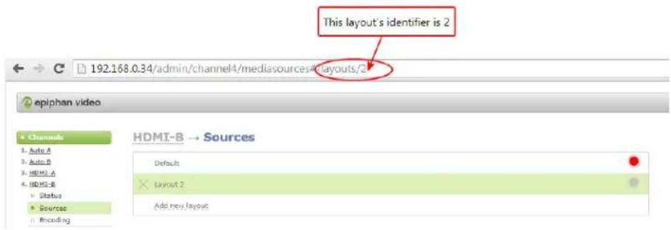
Table 70 Supported channel layout configuration keys
| Key Values Description | |
| active_layout integer | Specifies which layout is currently active for the specified channel. |
Audio configuration keys
The following audio configuration keys are supported. For more information on individual items listed, see Configure Encoding (Multi-source).
Table 71 Supported Audio configuration keys
| Key Values Description | ||
| audio | onempty string (""") | Enables or disables audio for the stream.To enable audio, set to on.To disable audio, set to an empty string ("""). |
| audiobitrate | 326496112128160192 | Specifies the audio bitrate for the stream.Not applicable for PCM audio codecs. |
| audiochannels | 1 (mono)2 (stereo) | Specifies the number of audio channels.For mono, set to 1.For stereo, set to 2. |
| audiopreset | CODECS:pcm_s161e (PCM)libmp3lame (MP3)libfacc (AAC)RATES:16000 (AAC only)220504410048000 | Specifies an audio code preset in the format CODEC;RATE.i.e. libfaac;22050 |
Stream publishing configuration keys
The system supports the following stream publishing settings. For more information on publishing the stream, see What is streaming?.
Table 72 Supported Stream Publishing configuration keys
| Key Values Description | ||
| publish_enabled | onoff / any other value | Starts or stops streaming to CDN servers (RTSP, RTMP type streaming including Original Livestream and Wowza Cloud).SeeStream to a CDN.To turn streaming on, set to on.To turn streaming off, set to off or to any other value. |
| publish_type | 0 (do not publish)2 (RTSP Announce)3 (multicast RTP/UDP)4 (multicast MPEG-TS over UDP)5 (multicast MPEG-TS over RTP/UDP)6 (RTMP push)7 (Wowza Streaming Cloud)8 (Original Livestream) | Specifies the type of stream publishing, if any. |
RTSP Announce configuration keys (Publish type 2)
The following settings are supported when the publish type is set to RTSP Announce. For more information on RTSP and these settings, seeTo stream content to a CDN using RTSP announceWhat is streaming?.
Table 73 Supported RTSP Announce configuration keys
| Key Values Description | ||
| rtsp_url string Specifies the RTSP server announce URL. | ||
| rtsp_transport | tcpudp or empty string (""") | Specifies the RTSP transport, either tcp or udp.Use udp or "" for udp transportUse tcp for tcp transport. |
| rtsp_username string Specifies the username for the RTSP server. | ||
| rtsp_password string Specifies the password for the RTSP server. | ||
RTP/UDP configuration keys (Publish type 3)
The following settings are supported when the publish type is set to RTP/UDP. For more information on RTP/UDP and these settings, see What is streaming?.
Table 74 Supported RTP/UDP configuration keys
| Key Values Description | ||
| unicast_address string (IP address) Specifies the unicast/multicast address. | ||
| unicast_aport | 1000...65535, but not 5557 | Specifies the UDP port for RTP/UDP audio streaming. Note port 5557 is used for network discovery and cannot be used for streaming. |
| unicast_vport | 1000...65535, but not 5557 | Specifies the UDP port for RTP/UDP video streaming. Note port 5557 is used for network discovery and cannot be used for streaming. |
MPEG-TS configuration keys (Publish types 4 and 5)
The following settings are supported when the publish type is set to MPEG-TS and for associated SAP distribution. For more information on MPEG-TS and these settings, see What is streaming? Viewing with Session Announcement Protocol (SAP).
Table 75 Supported MPEG-TS and SAP configuration keys
| Key Values Description | ||
| unicast_address string (IP address) Specifies the unicast/multicast address. | ||
| unicast_mport | 1000...65535, but not 5557 | Specifies the UDP port for MPEG-TS streaming. Note port 5557 is used for network discovery and cannot be used for streaming. |
| sap | onempty string ("") | Enables sharing of recorded files via SAP.To enable sharing files over SAP, set to on.To disable sharing files over SAP, set to an empty string (""). |
| sap_channel_no integer Specifies the SAP channel number. | ||
| sap_group string Specifies the SAP group name. | ||
| sap_ip string Specify the SAP announcement IP. | ||
RTMP push configuration keys (Publish type 6 and 7)
The following settings are supported when the publish type is set to RTMP Push. For more information on RTMP and these settings, see To stream content to a CDN using RTMP push and What is streaming?.
Table 76 Supported RTMP Push Configuration Keys
| Key Values Description | ||
| rtmp_url string Specifies the RTMP server | URL. | |
| rtmp_stream string Specifies the RTMP stream name, as configured with the CDN. | ||
| rtmp_username string Specifies the username for the RTMP server. | ||
| rtmp_password string Specifies the password for the RTMP server. | ||
Livestream configuration keys (Publish type 8)
The following settings are supported when the publish type is set to Original Livestream. For more information on these settings, see Stream to Original Livestream What is streaming?.
Table 77 Supported Livestream configuration Keys
| Key Values Description | ||
| livestream_channel | string | The channel name, configured at the Livestream server. |
| rtmp_username | string | Specifies the username for the Livestream server. |
| rtmp_password | string | Specifies the password for the Livestream server. |
Content metadata configuration keys
The following keys are available for configuration of the content's metadata.
Table 78 Supported Content Metadata Configuration Keys
| Key Values Description | ||
| author | string | Specifies the name of the author for the stream/recording. Refer to description above on handling white space (spaces) in the string. |
| comment | string | Specifies a comment for the stream/recording. Refer to description above on handling white space (spaces) in the string. |
| Key Values Description | |
| copyright string | |
| title string |
PART 6: Troubleshooting
Use the follow tables for help if you are experiencing problems or unexpected behavior from your Pearl-2.
Table 79 Troubleshooting
| Problem Action(s) to Resolve | |
| 4K features not working | The most likely problem is that the 4K Feature add-on is not activated. You can lean more about activating this feature here 4K |
| Not sure if the connected video inputs are being captured. | Check each source's input from the source preview in the Admin panel.ORCheck the touchscreen interface to view confidence monitoring for each channel. See Touchscreen overview.ORCheck the Dashboard interface in Epiphan Live. See Monitoring video and audio sources. |
| No sound is coming from an audio source. | Verify that you are using the correct audio input by following the steps in Configure encoding.ORCheck the audio meter from the Dashboard view in Epiphan Live. See Monitoring video and audio sources.ORCheck the touchscreen interface for audio monitoring or use the 3.5 mm audio jack on the front of Pearl-2 to verify audio. See Touchscreen overview. |
| Captured SDI audio contains audible "clicking" sound or other audio distortions upon playback. | Ensure audio sample rate is set to 48 kHz. Lower sample rates (i.e. 32 kHz and 44 kHz) can sometimes cause audio distortion. |
| Timestamps between Pearl-2 and an RTSP source are not synchronized. | Reconnect your RTSP source to reset desynchronized timestamps. Verify that you are using a local NTP server on your Pearl-2 as a time synchronization server for your RTSPsource. See Configure synchronized time (NTP, PTP v1 and RDATE). |
| Too much noise is present in the audio output. | Modify the Input Amplifier Volume parameter in the Audio menu. Start with setting it to 40% and reduce until the noise is no longer present. See for details on this setting. |
| Video playback is fine, but when I play the clip in Adobe Premiere Pro the audio and video are out of sync. | Adobe Premiere Pro has a known issue handling video that is recorded using a variable frame rate. Convert the clip to a constant frame rate using a third-party software, such as Handbrake, before editing in Adobe Premiere Pro. |
| Adobe Premiere Pro won't load my .mp4 recording from Pearl-2. | Check if the selected recording format in Pearl-2 is MP4-Fragmented. Adobe Premiere Pro does not currently support fragmented .mp4 files. Before editing in Adobe Premiere Pro, convert the clip to progressive .mp4 format. Run the file through ffmpeg or a third-party software such as Handbrake to preserve both audio and video output. |
| Image quality is poor or insufficient. | The following tips can help improve image quality:1. Ensure the source resolution is used as the output or recorded resolution. Up-scaling and down-scaling can affect picture quality.2. Increase the Bitrate value and/or decrease the Limit frame rate value in the Encoding menu. See Configure encoding. |
| Frames per second are lower than expected. | The following tips can help improve frames per second (fps):1. Increase the Limit frame rate value and/or decrease the Bitrate value in the Encoding menu. See Configure encoding.2. Reduce the number of actions happening simultaneously on the system (i.e. if streaming, recording, and copying files, consider waiting to copy files until after streaming and recording are complete).3. Enter a low negative value (i.e. -5) in the Frame Grabber's Vertical Shift field.4. Reduce the number of channels encoding data.5. Ensure the hardware-accelerated H.264 encoding preset is chosen for all channels. |
| Stream won't play in my media player or browser. | Verify that the Stream Type matches with the media player used and that you have the correct url or SDP file for the player. See Stream content using HTTP or RTSP and Stream to a media player or smart TV.If you still cannot see the stream, try disabling your local computer firewall.If the issue is still not resolved, contact Epiphan Support at support@epiphan.com. |
| The stream interrupts or the image breaks up. | The following tips can help diagnose image problems:1. Ensure the source resolution is used as the output or recorded resolution. Up-scaling and down-scaling can affect picture quality. Configure encoding .2. Increase the Bitrate value and/or decrease the Limit frame rate value in the Encoding menu. See Configure encoding .3. Check network settings including filters, routers and application settings. Packet loss can result in stream failure. |
| Recording issues. | If recording will not start, check the Disk Status Information to see if the system is out of disk space. See Check disk storage space and Recorded files. |
| Firmware upgrade fails. | Reboot the system and try again. If the problem persists, contact Epiphan support at support@epiphan.com. |
| Certain Media players won't play encoded videos but others will.Certain Media players won't play MOV videos. | Depending on the media player used, there could be different issues, including:1. On Windows 10, the Movies & TV app sometimes fails to playback MP4-fragmented files with MP3 audio: try changing your MP4 audio encoding to AAC.2. Streams and recordings at very low frame rates (e.g. 1 fps) are not playable in VLC media player, use Windows Media Player and Quicktime Player instead. |
| Some media players won't play MOV videos that are recorded with MP3 audio encoding, including:1. VLC 2.2.4 (Microsoft Windows) if MP3 audio encoding is at 48 kbps.2. Movies & TV 10.16122.1029 on Windows 10.3. Windows Media Player 12.Choose a different audio encoding when recording MOV files o use a different media player to playback the recording. | |
| Ubuntu not recognizing attached monitor | Legacy Ubuntu systems have poor support for HDMI 2.0, and does not recognize a monitor being plugged into Pearl-2 unless the monitor is plugged into Pearl-2 before the system is turned on. |
| Feature add-on purchase/activation not working | Currently, Pearl-2 requires internet access to activate new add-ons. If the system has internet access, ensure that there is no firewall preventing access to license.epiphan.com, Port 443. |
| In Epiphan Live, sources are sometimes invisible in the preview panel | This can occur if the image is too large for the panel. Check the size of the source, and ensure that constraints are applied to each corner of the layout. |
| Video output port is configured to display 4K video, but the video is not appearing on is configured to display working, but not appearing on the connected 4K monitor | Not all AOC brand monitors are compatible with HDMI 1.4 output. Check the brand of your monitor and attempt on different display. |
| System is not starting up correctly | Ensure there are no USB sticks inserted into the USB ports during power up. They may be conflicting with the internal hard drive, causing unexpected behavior. |
| I can't preview my channels using the Epiphan Live Dashboard on Chrome even after I updated the security certificate for my website | If you're using the Chrome browser on an HTTPS network and your website has an insecure or invalid security certificate, you can't preview any Pearl-2 channels using the Dashboard even after updating the security certificate in Chrome. Use a different web browser, such as Firefox, and add the security certificate for the website to the exceptions list. |
| Web camera is not working correctly. | There are several possible causes of poor performance on webcameras:The camera itself might be malfunctioning. Try hooking it into a computer to see if the problem remains.If the picture quality is below standard, try adjusting the settings using the instructions for how to Configure a sourceCheck that your web camera is on our list of supported models. If it is not, try using a supported camera, and if the problem persists, contact our support team. |
Limitations and known issues
This section includes known issues or limitations that affect functionality or usability and ways that you can work around these limitations.
Affecting encoding
- Limitation: When Pearl-2 is overloaded, video frames or audio samples can be dropped causing variable frame rate and audio cracks.
Workaround: Pearl-2 is a powerful system capable of many simultaneous tasks, but like any other computing device, it has finite resources. If this problem is observed, check the CPU load from your system's Info page. To reduce system load, do any of the following: disconnect unused video displays from Pearl-2's video output ports, delete unused channels and unused layouts, or reduce the complexity of layouts by scaling at the source instead of having the system scale, or reduce the number of sources in layouts, or reduce the frame size or frame rate for channels displayed on the video output ports. Note that actions performed in the Admin panel and Epiphan Live can increase overhead (such as adding channels/sources to Epiphan Live's Dashboard preview panels), as can switching layouts via Pearl-2's touch screen.
• Video bitrate for MJPEG streams is larger than the configured value.
Workaround: Verify the actual bitrate on the channel's channel status page when there are connected viewers. If lower bitrates are important, select another codec.
• Encoding video at 60 fps with either 16 kHz or 22 kHz AAC audio can result in some dropped video frames.
Workaround: Select another video frame rate, a different audio sampling rate, or choose MP3 audio.
- Configuring very low frame rates such as 1 fps encoding with a high bitrate setting (e.g. 7000 kbps) results in poor video quality.
Workaround: Allow Pearl-2 to automatically select the best bitrate setting. For 1 fps, this results in a bitrate of about 1180 kbps.
- When using an AV.io 4K video capture card in 1280x720 at 60 fps, over time the audio timestamps become unsynchronized. This causes the audio to periodically disappear from the stream and the pipeline to restart. Audio is eventually recovered.
Workaround: Use a different resolution or frame rate setting on the AV.io 4K.
- Occasionally, a solid black image appears when connecting an AV.io HD capture card to a USB port on Pearl-2.
Workaround: Reconnecting the capture card resolves the issue and captures the video normally.
- Some audio distortion is heard on video output port using PCM 22 kHz encoding or very low frame rate (1-5 fps).
Workaround: For best results, use AAC 48 kHz or PCM 48 kHz audio encoding and encode the channel at higher than 5 frames per second.
Affecting streaming and recording
- When using the Admin panel to switch layouts while streaming or recording, it's possible to have a small number of frames (approximately 100 ms worth) repeated in the stream or recording file, and over the same time period a small number of frames from the new layout skipped. An audible stutter may also be heard on the HDMI output.
Workaround: If dropped frames are problematic for your application, avoid using the Admin UI to switch
layouts. Use Epiphan Live or the touchscreen to switch instead.
- Streaming status on the touch screen does not include Wowza Streaming Cloud transcoder settings.
Workaround: Start the transcoder from the Pearl-2 or Wowza web UI.
• Interlaced SDI capture is sometimes shifted downwards, resulting in a small green line at the top of the video.
Workaround: This issue varies with different sources. If it is affecting your capture, the best solution is to crop out the green line in your layout.
- During recording if the touchscreen is used to switch layouts, headphones attached to the audio jack on the front of Pearl-2 sometimes pick up audio crackling and pops during the switching process.
Workaround: Note that these artifacts do not affect the final recording, only the audio monitoring feature. To avoid the disruption to audio confidence monitoring, use the Pearl-2 Admin Panel or Epiphan Live to switch between layouts.
- Extracting tracks from an .MP4 recording when there isn't enough storage space for the extracted files causes the extracted files to become corrupted.
Workaround: Check how much internal storage space is available on Pearl-2 and delete any unnecessary recordings to free up more space.
• Occasionally, tracks won't extract from a 64 GB .AVI multi-track recording using the Admin UI.
Workaround: Perform the extraction again.
Affecting the Admin panel
- Passwords and IP restrictions set for viewers don't restrict access when using certain common platforms or when set on a per-channel basis if your stream uses HTTP Live Streaming (HLS) because HLS is processed directly by the apache server.
Workaround: This only applies if you're using a password for the stream. The only common platforms where this is a know issue are VLC and iPhone6, iOS 10.0.1, and using another platform prevents the issue. If you're streaming over HLS, do not set viewer passwords and IP restrictions per-channel. Use global viewer passwords and IP allow/deny lists instead.
- It is possible to name two or more channels with the same value. Use of automatic file transfer and UPnP is unpredictable if this occurs.
Workaround: Ensure each channel has a unique name.
- The automatic file upload (AFU) file queue shows a maximum of 15 files, Newer 15 and Top of the list buttons do not work. All files are transferred, even though they are not listed.
Workaround: Wait for the queue to have fewer files in the list. Use global viewer passwords and IP allow/deny lists instead.
- Cropping a video source to 16:9 using the layout editor may not scale correctly and can appear as a thin line in the layout editor. This happens when the device or web browser your using with the admin interface has a different approach to composing layout. Recording and streaming are not affected.
Workaround: Due to color space limitations (YUV with 2x2 subsampling), the cropped region's dimensions must be set to even values.
- Authentication to Pearl-2 using DNS login will often fail for Windows Edge, and on Mac OS X 10.10 with Safari, Chrome, and Firefox.
Workaround: Use a different web browser such as Chrome or Internet Explorer, or use a different OS.
- When streaming to the Wowza streaming cloud, the Transcoder state field always displays a status of "starting" even after the stream has started.
- The special preview mode that lets you preview all channels at once using a web browser isn't functioning.
Workaround: Preview individual channels using different tabs in your web browser.
Affecting Epiphan Live
- Streaming status on the Epiphan Live Dashboard interface (and touch screen) does not include information regarding Wowza Streaming Cloud transcoder settings.
Workaround: When streaming to Wowza, ensure the transcoder in the Wowza Streaming Cloud web interface is enabled. - The green and red borders around the "Preview" and "Live" areas in the Channel section are offset from the video by a few pixels.
Workaround: The offset is cosmetic and does not affect your Live stream, so no workaround is required. - For interlaced HDMI video sources, the letter "P" appears next to the frame size for the Video input instead of the letter "I".
- When a HDMI output assigned to a Dashboard preview panel has its source changed, the preview panel does not automatically update to reflect the change.
Workaround: Refresh the Epiphan Live Dashboard in your web browser to update any changes in your preview panels.
• After refreshing Epiphan Live, a prompt appears to Take Over Session, despite being logged in.
Workaround: Selecting Take Over Session does not stop your session, but rather continues it. Select Take Over Session to continue your session.
Affecting video output ports
- Connecting an external monitor to the HDMI 1 port while Pearl-2 is powered on may cause the monitor to not be detected.
Workaround: Connect an external monitor to the HDMI 1 port before turning on Pearl-2.
Affecting USB devices
- For the IPEVO Ziggi-HD Plus web camera, you must enable the power line frequency setting in the web camera before connecting the camera to Pearl-2.
- The timestamp on the last recorded video frame from a Logitech BRIO 4K camera in 4K mode at 30 fps is approximately 200 ms out of synchronization with the timestamp on the last frame recorded from the same camera when in full HD mode. However, the actual recorded content in Pearl-2 is identical in both modes.
Affecting other areas
- AFU to Amazon Web Services S3 Simple Cloud Storage transfer sometimes does not recover after the network connection is cut. The expected behavior is that the file transfer would restart, but there is sometimes a time desync that results in a failed transfer.
Workaround: If the network connection is severed during a AFU transfer, the process must be restarted from the beginning, and the transfer must proceed without interruptions to the network.
- Software-initiated reboot of Pearl-2 sometimes results in failure to recover.
Workaround: When possible, use the power button on the front of Pearl-2 to restart the system. If a software reboot is used and the system does not restart as expected, use the power button to try restarting it, or unplug the system for 10 seconds, then re-insert the power cord and use the power button.
- Prolonged operation of Pearl-2 in high temperature environments may cause the system to become unresponsive and stop recording and/or streaming.
Workaround: If Pearl-2 becomes unresponsive, use the power button to perform a system restart.
- Pearl-2 doesn't synchronize time from a local Windows NTP server.
Workaround: Avoid using a local Windows NTP server with Pearl-2.
Previous releases and features
This section outlines the features introduced with previous product releases.
Release 4.4.0
- Constant frame rate
- Audio VU meter
- Epiphan Live preview on HTTPS networks
• AFU to an SCP server remote directory creation
Release 4.3.0
- Chroma keying
• Text overlay and custom layout editor enhancements - Clone channels and custom layouts
- Clone recorders and recorder metadata
- AFU enhancements
- Start and stop individual streams using Epiphan Live
• Logitech BRIO 4K camera support
Release 4.2.0
• USB 3.0 support for web cameras and AV.io UVC video capture cards
• Fully integrated multi-publishing
• Enhanced video cropping
• Audio delay control
• Epiphan Live recordings management
Release 4.0.1
- Launch of Pearl-2 Rackmount models
- 4K add-on
- Inaugural release of Pearl-2 with the following features
• Capture 6 video sources at once
- Epiphan Live
- Switch video sources live
• Pro video inputs and outputs
- Pro audio inputs
• 512 GB data storage (SSD)
- Touchscreen
Software license
ATTENTION: THE SOFTWARE AND DOCUMENTATION PROVIDED UNDER THIS AGREEMENT ARE BEING LICENSED TO YOU BY EPIPHAN SYSTEMS INC. ("LICENSOR") AND ARE NOT BEING SOLD. THIS AGREEMENT CONTAINS LIMITATIONS ON REPRESENTATIONS, WARRANTIES, CONDITIONS, REMEDIES, AND LIABILITIES THAT ARE APPLICABLE TO THE SOFTWARE AND DOCUMENTATION.
Epiphan Systems Inc.
Software License
IMPORTANT: BEFORE DOWNLOADING, INSTALLING, OR USING THE SOFTWARE AND DOCUMENTATION, PLEASE CAREFULLY READ THIS AGREEMENT WHICH CONTAINS THE TERMS AND CONDITIONS UNDER WHICH YOU ARE ACQUIRING A LICENSE TO USE THE SOFTWARE AND DOCUMENTATION. IF YOU DO NOT ACCEPT THE TERMS AND CONDITIONS OF THIS AGREEMENT PLEASE DO NOT DOWNLOAD, INSTALL, OR USE THE SOFTWARE AND DOCUMENTATION AND PROMPTLY RETURN OR DESTROY THE SOFTWARE AND DOCUMENTATION. IF YOU DOWNLOAD, INSTALL, OR USE THE SOFTWARE AND/OR DOCUMENTATION, YOU WILL HAVE ACCEPTED AND AGREED TO THESE TERMS AND CONDITIONS. THE SOFTWARE, HARDWARE AND DOCUMENTATION ARE ALSO PROTECTED BY COPYRIGHT LAWS AND INTERNATIONAL COPYRIGHT TREATIES, AS WELL AS OTHER INTELLECTUAL PROPERTY LAWS. IF YOU ARE AN AGENT OR EMPLOYEE OF AN ENTITY, YOU REPRESENT AND WARRANTY THAT (I) THE INDIVIDUAL ACCEPTING THIS AGREEMENT IS DULY AUTHORIZED TO ACCEPT THIS AGREEMENT ON SUCH ENTITY'S BEHALF AND TO BIND SUCH ENTITY, AND (II) SUCH ENTITY HAS FULL POWER, CORPORATE OR OTHERWISE, TO ENTER INTO THIS AGREEMENT AND PERFORM ITS OBLIGATIONS UNDER THIS AGREEMENT.
1. Definitions: In this Agreement:
"Agreement" means this Epiphan Systems Inc. Software License;
"API" means an application programming interface;
"Documentation" means the technical publications delivered to You with the Software relating to the installation and operation of the Software and/or Hardware, such as reference, user, installation and technical guides and release notes;
"Epiphan" means Epiphan Systems Inc;
"Epiphan Hardware Product" means an Epiphan hardware product (including enclosure and mechanical parts, circuitry and electrical and electronic components contained therein) purchased by You, which is intended to be used in conjunction with the licensed Software and Documentation;
"License Key" means a series of computer-generated characters used for the purpose of controlling the operation of Epiphan Hardware Products and/or related Software;
"Software" means the Licensor binary and/or bytecode software and/or firmware programs that are (i) specified in Your Order or that are included with or in the Epiphan Hardware Products specified in Your Order, (ii) are made available to You for download after acceptance of this Agreement, (iii) are packaged with this Agreement, (iv) pre-installed on Epiphan Hardware Products, (v) embed this Agreement in their installer(s) and
which are installed after acceptance of this Agreement, or (vi) embed this Agreement in their product documentation. Software also includes the related Documentation;
"You" or "Your" means the individual acquiring the Software license or any entity on whose behalf such individual is acting. In the case of an entity, "You" includes any entity that by majority voting interest controls, is controlled by, or is under common control with You; and
"Your Order" means (i) the web forms provided by Epiphan or its applicable reseller or distributor for ordering Epiphan Hardware Products and related Software licenses, or (ii) written documents executed by Epiphan, or one of its resellers or distributors, and You in respect to Your purchases of Epiphan Hardware Products and/or related Software licenses.
-
Grant of Software License: Subject to the terms and conditions of this Agreement, including payment of any applicable fees specified in Your Order, Licensor grants You a non-exclusive, non-transferable, non-sublicensable, internal license to use the number of copies of the Software specified in Your Order and to use the Software functions specified in Your Order solely for operation on the Epiphan Hardware Products for which such Software has been designed as specified in the Documentation for such Software. If the number of copies of Software is not specified in Your Order, then the number of copies shall be a reasonable number of copies. You acknowledge and agree that the ability to use certain Software functions is controlled by a Licensing Key and that You will not be able to use such functions unless You have paid the applicable fees charged by Epiphan for the right to use such functions and to receive a Licensing Key to enable such functions. For functions that are controlled by a Licensing String You shall only use that Licensing String with the copy of the Software for which it was issued and You shall not use that copy of the Licensing String with any other copies of the Software that You may have or make. All copies of the Software made by You shall include all trademarks, copyright notices, restricted rights legends, proprietary markings and the like exactly as they appear on the copy of the Software originally provided to You. No other rights in the Software or Documentation are granted to You.
-
Open Source Software: Binary, bytecode and source code versions of certain open source software packages may be embedded in or distributed with the Software ("Open Source Software"). If a separate license agreement for an item of open source software is: delivered to You with the Software; included in the download package for the Software; referenced in any material (including the Documentation) that is included in the download or distribution package for the Software; or listed at www.epiphan.com/opensource, then such open source software shall be Open Source Software and such separate license agreement shall govern Your use of that item or version of such open source software. The Open Source Software may include free software (i.e. software licensed under the GNU Lesser General Public License or other free software licenses) for which the applicable free software license may also require that the source code for such free software be made available to those receiving only executable versions of such free software. If the source code for any free software distributed with the Software is not provided with the Software, then upon request, within a three (3) year period from the original receipt of the binary or bytecode version of such Open Source Software from Licensor, for a fee that shall not exceed Licensor's costs associated with the shipping of the source code for such free software, Licensor will provide a copy of the source code for such free software to You.
-
Restrictions: The terms set forth in this Section 4 are additional conditions to the licenses granted in Section 2. Your right to use the Software is conditioned upon Your timely payment of the full amount of fees due for: (i) the Epiphan Hardware Product(s) on which You want to use the Software; (ii) all support agreements You have entered into with Licensor or any of its distributors and/or resellers; (iii) licensed Software and Documentation.
You shall not reverse engineer, disassemble, reverse translate, decompile or in any other manner decode any Epiphan Hardware Product or Software except to the extent the Software is distributed with any Open Source Software that prohibits the imposition of such a restriction or to the extent the foregoing restriction is expressly prohibited by applicable law notwithstanding a contractual obligation to the contrary. You acknowledge and agree that no rights in respect to the source code of the Software are granted to You. You acknowledge and agree that the rights in respect to use of the Software and Documentation are granted only for use in conjunction with Epiphan Hardware Products. You shall not distribute, lease, rent, grant a security interest in, assign, or otherwise transfer the Software except as expressly provided in this Agreement. You shall not modify or create any derivatives works of the Software or merge all or any part of the Software with another program. Notwithstanding the foregoing, You may call public APIs made available by Epiphan in the Software from applications developed by or on Your behalf provided that such applications do not embed any of the Software other than the minimum linkage materials required to call separately running instances of the Software. You shall not use the Software or make the Software available to any third parties as part of any service bureau, time sharing service, application service provider offering, software-as-a-service offering or any other managed service offering. You shall not disclose any performance, benchmarking, or feature-related information about the Software. You further agree not to disclose, transfer or otherwise provide to any third party any portion of the Software, except as expressly permitted herein.
Some Epiphan Hardware Products and Software embed third-party APIs that integrate with third-party party services ("Third-Party Services") to allow users of such Epiphan Hardware Products and Software to interact with such Third-Party Services for various capabilities offered by such Third-Party Services, such as, and without limitation, authentication, uploading and downloading of video content and other features made available by such Third-Party Services. If You access or use any Third-Party Service and/or related APIs using an Epiphan Hardware Product and/or the Software then You shall comply with all of the terms and conditions for such Third-Party Service and/or related APIs.
- Disclaimer of Warranties: EXCEPT FOR ANY WARRANTIES THAT MAY BE PROVIDED IN ANY COMMERCIAL AGREEMENT EXECUTED BETWEEN YOU AND LICENSOR (OR BETWEEN YOU AND ONE OF LICENSOR'S RESELLERS OR DISTRIBUTORS), THE EPIPHAN HARDWARE PRODUCTS, SOFTWARE AND/OR DOCUMENTATION ARE PROVIDED "AS IS", WITHOUT ANY REPRESENTATIONS, CONDITIONS, AND/OR WARRANTIES OF ANY KIND. WITHOUT LIMITATION, LICENSOR AND ITS AFFILIATES AND ITS AND THEIR LICENSORS, SUPPLIERS, SUBCONTRACTORS, RESELLERS AND DISTRIBUTORS DISCLAIM ANY AND ALL IMPLIED REPRESENTATIONS, CONDITIONS AND/OR WARRANTIES OF MERCHANTABILITY, MERCHANTABILITY QUALITY, NON-INFRINGEMENT, DURABILITY, COMPATIBILITY, TITLE, SATISFACTORY QUALITY AND/OR FITNESS FOR A PARTICULAR PURPOSE WHETHER ARISING BY STATUTE, COURSE OF DEALING, USAGE OF TRADE OR OTHERWISE. EXCEPT AS OTHERWISE EXPRESSLY PROVIDED IN ANY COMMERCIAL AGREEMENT EXECUTED BETWEEN YOU AND LICENSOR (OR BETWEEN YOU AND ONE OF LICENSOR'S RESELLERS OR DISTRIBUTORS), THE ENTIRE RISK OF THE USE OF THE EPIPHAN HARDWARE PRODUCTS, SOFTWARE AND/OR DOCUMENTATION SHALL BE BORNE BY YOU. EXCEPT AS OTHERWISE EXPRESSLY PROVIDED IN ANY COMMERCIAL AGREEMENT EXECUTED BETWEEN YOU AND LICENSOR (OR BETWEEN YOU AND ONE OF LICENSOR'S RESELLERS OR DISTRIBUTORS), NEITHER LICENSOR NOR ANY OF ITS AFFILIATES NOR ANY OF ITS OR THEIR LICENSORS, SUPPLIERS, SUBCONTRACTORS, RESELLERS AND/OR DISTRIBUTORS MAKE ANY REPRESENTATIONS OR PROVIDE ANY CONDITIONS AND/OR WARRANTIES ABOUT THE SUITABILITY OF THE EPIPHAN HARDWARE PRODUCTS, SOFTWARE, SERVICES AND/OR DOCUMENTATION. NEITHER LICENSOR NOR ANY OF ITS AFFILIATES NOR ANY ITS OR THEIR LICENSORS, SUPPLIERS, SUBCONTRACTORS, RESELLERS AND/OR DISTRIBUTORS MAKE ANY REPRESENTATIONS OR PROVIDE
ANY CONDITIONS AND/OR WARRANTIES WHATSOEVER ABOUT ANY INFORMATION AND/OR DATA THAT MAY BE PROCESSED BY OR MADE AVAILABLE USING ANY EPIPHAN HARDWARE PRODUCT AND/OR SOFTWARE OR ABOUT ANY THIRD-PARTY SERVICE THAT MAY BE ACCESSIBLE USING ANY EPIPHAN HARDWARE PRODUCT AND/OR SOFTWARE.
- LIMITATION OF LIABILITY: NEITHER LICENSOR NOR ANY OF ITS AFFILIATES NOR ANY OF ITS OR THEIR LICENSORS, SUPPLIERS, SUBCONTRACTORS, RESELLERS AND/OR DISTRIBUTORS SHALL HAVE ANY LIABILITY TO YOU OR ANY OTHER PERSON OR ENTITY FOR ANY DAMAGES ARISING FROM THIS AGREEMENT, RELATING TO THE HARDWARE, SOFTWARE OR DOCUMENTATION, OR RELATING TO ANY SERVICES PROVIDED TO YOU BY LICENSOR (INCLUDING ITS AFFILIATES AND ITS AND THEIR LICENSORS, SUPPLIERS, SUBCONTRACTORS, RESELLERS AND/OR DISTRIBUTORS) IN RELATION TO THE EPIPHAN HARDWARE PRODUCTS, SERVICES, SOFTWARE AND/OR DOCUMENTATION FOR ANY INDIRECT, RELIANCE, INCIDENTAL, SPECIAL, PUNITIVE, EXEMPLARY OR CONSEQUENTIAL DAMAGES, INCLUDING, BUT NOT LIMITED TO, LOSS OF REVENUE OR PROFIT, LOSS OF OR DAMAGE TO DATA, BUSINESS INTERRUPTION, LOSS OF DATA, REPLACEMENT OR RECOVERY COSTS, OR OTHER COMMERCIAL OR ECONOMIC LOSS, WHETHER ARISING FROM CONTRACT, EQUITY, TORT (INCLUDING NEGLIGENCE OR STRICT LIABILITY) OR ANY OTHER THEORY OF LIABILITY, EVEN IF LICENSOR (INCLUDING ITS AFFILIATES AND ITS AND THEIR LICENSORS, SUPPLIERS, SUBCONTRACTORS, RESELLERS AND/OR DISTRIBUTORS) HAVE BEEN ADVISED OF THE POSSIBILITY OF SUCH DAMAGES, OR THEY ARE FORESEEABLE. THE LIMITATIONS IN THIS SECTION SHALL APPLY WHETHER OR NOT THE ALLEGED BREACH OR DEFAULT IS A BREACH OF A FUNDAMENTAL CONDITION OR TERM OR FUNDAMENTAL BREACH. SOME JURISDICTIONS DO NOT ALLOW THE EXCLUSION OR LIMITATION OF LIABILITY FOR CONSEQUENTIAL OR INCIDENTAL DAMAGES, SO THESE LIMITATIONS MAY NOT APPLY TO YOU. IN NO EVENT SHALL THE TOTAL CUMULATIVE LIABILITY OF LICENSOR (INCLUDING ITS AFFILIATES AND ITS AND THEIR LICENSORS, SUPPLIERS, SUBCONTRACTORS, RESELLERS AND DISTRIBUTORS) TO YOU OR ANY OTHER PERSON OR ENTITY FOR ANY DAMAGES ARISING FROM THIS AGREEMENT, RELATING TO THE EPIPHAN HARDWARE PRODUCTS, SOFTWARE, DOCUMENTATION AND/OR RELATING TO ANY SERVICES PROVIDED TO YOU BY LICENSOR (INCLUDING ITS AFFILIATES AND ITS AND THEIR LICENSORS, SUPPLIERS, SUBCONTRACTORS, RESELLERS AND DISTRIBUTORS) IN RELATION TO THE EPIPHAN HARDWARE PRODUCTS, SOFTWARE AND/OR DOCUMENTATION, EXCEED THE LICENSE FEES PAID BY YOU FOR THE SOFTWARE.
NOTWITHSTANDING ANY OTHER PROVISION IN THIS AGREEMENT, NEITHER LICENSOR NOR ANY OF ITS AFFILIATES OR ITS OR THEIR LICENSORS, SUPPLIERS, SUBCONTRACTORS, RESELLERS AND/OR DISTRIBUTORS SHALL HAVE ANY LIABILITY TO YOU OR ANY OTHER PERSON OR ENTITY WHATSOEVER IN RESPECT TO ANY DIRECT, INDIRECT, RELIANCE, INCIDENTAL, SPECIAL, PUNITIVE, EXEMPLARY OR CONSEQUENTIAL DAMAGES, INCLUDING, BUT NOT LIMITED TO, LOSS OF REVENUE OR PROFIT, LOSS OF OR DAMAGE TO DATA, BUSINESS INTERRUPTION, LOSS OF DATA, REPLACEMENT OR RECOVERY COSTS, OR OTHER COMMERCIAL OR ECONOMIC LOSS, ARISING FROM OR RELATING TO ANY INFORMATION AND/OR DATA THAT MAY BE PROCESSED BY OR MADE AVAILABLE USING ANY EPIPHAN HARDWARE PRODUCT AND/OR SOFTWARE OR ARISING FROM OR RELATING TO ANY THIRD-PARTY SERVICE THAT MAY BE ACCESSIBLE USING ANY EPIPHAN HARDWARE PRODUCT AND/OR SOFTWARE.
THE DISCLAIMER OF REPRESENTATIONS, WARRANTIES AND CONDITIONS AND LIMITATION OF LIABILITY CONSTITUTE AN ESSENTIAL PART OF THIS AGREEMENT. YOU ACKNOWLEDGE THAT BUT
FOR THE DISCLAIMER OF REPRESENTATIONS, WARRANTIES AND CONDITIONS AND LIMITATION OF LIABILITY, NEITHER LICENSOR NOR ANY OF ITS AFFILIATES OR ITS OR THEIR LICENSORS, SUPPLIERS, RESELLERS OR DISTRIBUTORS WOULD GRANT THE RIGHTS GRANTED IN THIS AGREEMENT.
-
Term and Termination: This Agreement shall continue for as long as You use the Software, however, it may be terminated sooner as provided in this Section 7. You may terminate this Agreement by destroying all copies of the Software and Documentation under Your control and providing certification of such destruction to Licensor or by returning the Software to Licensor. Licensor may terminate this Agreement immediately by providing You with written notice if: (a) You are in material breach of any provision of this Agreement, which breach, if capable of being cured, is not cured within thirty (30) days after Licensor gives You written notice thereof; or (b) You have committed a non-curable material breach of this Agreement. Upon termination You shall destroy all copies of the Software and Documentation. In addition to this Section, the Sections entitled Definitions, Disclaimer of Warranties, Limitation of Liability, Title, Indemnities, High-Risk Activities, Intellectual Property, and General shall continue in force even after any termination of this Agreement. No termination of this Agreement will entitle You to a refund of any amounts paid by You to Licensor or any reseller or distributor or affect any obligations You may have to pay any outstanding amounts owing to Licensor or any reseller or distributor. Upon any termination of this Agreement, Your license to the Software and Documentation will terminate and You shall destroy all copies of the Software and Documentation under Your control and certify such destruction to Licensor.
-
Support and Updates: This Agreement does not grant You the right to any updates or enhancements of the Software or the right to receive any technical support for the Software. Such updates and other technical support services, if available, may be purchased separately from Licensor or one of Licensor's resellers or distributors. Use of any updates or enhancements to the Software provided pursuant to any technical support You may procure from Licensor or one of Licensor's resellers or distributors shall be governed by the terms and conditions of this Agreement. Licensor reserves the right at any time not to release or to discontinue the release of any Software and to alter prices, features, specifications, capabilities, functions, licensing terms, release dates, general availability or other characteristics of the Software.
-
Title: All right, title, and interest (including all intellectual property rights) in, to, and under the Software (including all copies thereof) shall remain with Licensor and its licensors.
-
Indemnities: You shall indemnify, defend and hold Licensor, its affiliates, its and their licensors, suppliers, subcontractors, resellers and/or distributors and all of the directors, officers, employees of all of the foregoing (collectively the "Indemnified Parties") harmless from and against any damages, losses, liabilities, expenses, costs, claims, demands, actions, suits and/or proceedings incurred by the Indemnified Parties as a result of (i) Your use of the Epiphan Hardware Products, Software and/or Documentation, (ii) any use of the Epiphan Hardware Products, Software and/or Documentation on Your behalf, (iii) the use of the Epiphan Hardware Products, Software and/or Documentation by anyone to whom You give the Epiphan Hardware Products, Software and/or Documentation, and/or (iv) the use of the Epiphan Hardware Products, Software and/or Documentation on behalf of anyone to whom You give the Epiphan Hardware Products, Software and/or Documentation, including, without limitation, in all of the foregoing cases, any damages, losses, liabilities, expenses, costs, claims, demands, actions, suits and/or proceedings arising from or relating to any information and/or data that may be processed by or made available using any Epiphan Hardware Product and/or Software or arising from or relating to any Third-Party Service that may be accessible using any Epiphan Hardware Product and/or Software (collectively, each matter falling within any of the foregoing, a "Claim"), including, without limitation, indemnifying, defending and holding the Indemnified Parties harmless from and against any settlements agreed by You in connection with any Claims and/or any damages, costs or other
amounts (including reasonable attorneys' fees) awarded to a third party against any of the Indemnified Parties by a court or tribunal of competent jurisdiction in respect to any Claim. If You do not timely defend against or resist a Claim after notice from Licensor, Licensor shall be entitled to investigate, defend, compromise, settle, or otherwise dispose of the Claim, and incur costs in connection therewith, at Your expense, in such manner as Licensor deems in its best interests until a reasonable time after You comply with its obligations under this Section 10. You shall not enter into a settlement of any Claim without the Licensor's written consent unless such settlement is solely for monetary payment by You and contains an express, complete, unconditional release of all of the Indemnified Parties and which does not impose any obligations or restrictions on any of the Indemnified Parties.
-
High-Risk Activities: The Software and Epiphan Hardware Products are not fault-tolerant and are not designed, manufactured or intended for use in or in conjunction with on-line control equipment in hazardous environments requiring fail-safe performance, such as in the operation of nuclear facilities, aircraft navigation systems, air traffic control, or direct life support machines. Licensor, its licensors, suppliers, subcontractors, resellers and distributors specifically disclaim any express or implied representations, warranties and/or conditions for such uses.
-
U.S. Government End-Users: The Software and Documentation are each a "commercial item" as that term is defined at FAR 2.101, consisting of "commercial computer software" and "commercial computer software documentation" as such terms are defined in FAR 12.212, and are provided to the U.S. Government only as commercial end items. Government end users acquire the rights set out in this Agreement for the Software, Epiphan Hardware Products and Documentation consistent with: (i) for acquisition by or on behalf of civilian agencies, the terms set forth in FAR12.212; or (ii) for acquisition by or on behalf of units of the Department of Defense, the terms set forth in DFARS 227.7202. Use of the Epiphan Hardware Products, Software and Documentation is further restricted by the terms and conditions of this Agreement and the applicable commercial purchase agreement for the Epiphan Hardware Products. For the purposes of any applicable government use, the Epiphan Hardware Products, Software and Documentation were developed exclusively at private expense, and are trade secrets of Epiphan Systems Inc. for the purpose of any Freedom of Information legislation or any other disclosure statute, regulation or provision.
-
Export Restrictions: The Epiphan Hardware Products, Software, Documentation and related information are subject to export and import restrictions. By downloading, installing, or using the Software, Epiphan Hardware Products, Documentation and/or related information, You are representing and warranting that You are not located in, are not under the control of, and are not a national or resident of any country to which the export of the Epiphan Hardware Products, Software, Documentation and/or related information would be prohibited by the laws and/or regulations of Canada or the United States. You are also representing and warranting that You are not an individual to whom the export of the Epiphan Hardware Products, Software, Documentation or related information would be prohibited by the laws and/or regulations of Canada or the United States. You shall comply with the export laws and regulations of Canada and the United States that are applicable to the Epiphan Hardware Products, Software, Documentation and related information and You shall also comply with any local laws and/or regulations in Your jurisdiction that may impact Your right to export, import, or use the Epiphan Hardware Products, Software, Documentation or related information, and You represent and warrant that You have complied with any such applicable laws and/or regulations. The Epiphan Hardware Products, Software, Documentation and related information shall not be used for any purposes prohibited by export laws and/or regulations, including, without limitation, nuclear, chemical, or biological weapons proliferation. You shall be responsible for procuring all required
permissions for any subsequent export, import, or use of the Epiphan Hardware Products, Software, Documentation or related information.
-
Intellectual Property: Epiphan, Epiphan Systems and Epiphan Video are tradenames, trademarks or registered trademarks of Epiphan Systems Inc. in certain countries. All Licensor product names and logos are trademarks or registered trademarks of Epiphan Systems Inc. in certain countries. All other company and product names and logos are trademarks or registered trademarks of their respective owners in certain countries. You shall not disclose, transfer or otherwise provide to any third party any portion of the Software, except as expressly permitted in this Agreement.
-
General: This Agreement is the entire agreement between You and Licensor in respect to the Software, superseding any other agreements or discussions, oral or written. The terms and conditions of this Agreement shall prevail over any pre-printed terms on any quotes, orders, purchase orders, or purchase order acknowledgements, and shall prevail over any other communications between the parties in relation to the Software. You may not assign this Agreement whether voluntarily, by operation of law, or otherwise without Licensor's prior written consent. Licensor may assign this Agreement at any time without notice. The failure of a party to claim a breach of any term of this Agreement shall not constitute a waiver of such breach or the right of such party to enforce any subsequent breach of such term. If any provision of this Agreement is held to be unenforceable or illegal, such decision shall not affect the validity or enforceability of such provisions under other circumstances or the remaining provisions of this Agreement and such remaining provisions shall be reformed only to the extent necessary to make them enforceable under such circumstances. This Agreement shall be governed by the laws of the Province of Ontario and the laws of Canada applicable therein. No choice or conflict of laws rules of any jurisdiction shall apply to this Agreement. You shall only be entitled to bring any action or proceeding arising out of or relating to this Agreement, the Epiphan Hardware Products, Software, Documentation or any services provided in respect to the Epiphan Hardware Products, Software and/or Documentation in a court in Ottawa, Ontario, Canada, and You consent to the jurisdiction of such courts for any such action or proceeding. You waive all rights that You may have or that may hereafter arise to contest the jurisdiction of such courts for any action or proceeding brought by You. You hereby waive any right You may have to request a jury trial with respect to any action brought by You in connection with this Agreement, the Epiphan Hardware Products or Software or any services provided in respect to the Epiphan Hardware Products or Software. The application of the United Nations Convention on Contracts for the International Sale of Goods to this Agreement is expressly excluded.
October 6, 2016
© 2006-2016. Epiphan Systems Inc. All Rights Reserved.
Environmental Information
The equipment that you bought has required the extraction and use of natural resources for its production. It may contain hazardous substances that could impact health and the environment. In order to avoid the dissemination of those substances in our environment and to diminish the pressure on the natural resources, we encourage you to use the appropriate take-back systems. Those systems will reuse or recycle most of the materials of your end life equipment in a sound way. The crossed-out wheeled bin symbol invites you to use those systems. If you need more information about collection, reuse and recycling systems, please contact your local or regional waste administration. You can also contact us for more information on the environmental performance of our products.
Important Safety Warnings
WARNING: This product has no user-serviceable parts and the battery used in this device is not replaceable. Do not attempt to disassemble. Return the device for service.
CAUTION, RISK OF ELECTRIC SHOCK: This device may have multiple AC power cords installed. All power sources shall be disconnected before servicing to avoid shock hazard.
ATTENTION: Cet appareil ne contient aucun composant pouvant être entretenu ou réparé par l'utilisateur. En cas de panne, retourner l'appareil pour réparation.
ATTENTION, RISQUE DE CHOC ÉLECTRIQUE: Cet appareil peut être équipé de multiples cordons d'alimentation en courant alternatif. Pour placer cet appareil hors tension, débrancher tous les cordons d'alimentation sans exception.
FCC & CE Compliance Statement
This device complies with Part 15 of the FCC Rules. Operation is subject to the following two conditions:
- This device may not cause harmful interference
- This device must accept any interference received, including interference that may cause undesired operation.
Marking by the symbolC indicates compliance of this device with EMC directive of the European Community and meets or exceeds the following technical standard.
EN 55022 - Limits and Methods of Measurement of Radio Interference Characteristics of Information Technology Equipment.
FCC€
Other Jurisdictional Issues
Epiphan makes no representation that its products or information in this document or its web site is appropriate or available for use in your jurisdiction. Those who choose to access the Epiphan web site or use Epiphan products do so on their own initiative and are responsible for compliance with local laws, if and to the extent local laws are applicable
Submissions to Epiphan and Affiliated Servers
Any information, including but not limited to remarks, suggestions, ideas, graphics, or other submissions, communicated to Epiphan through their Epiphan web site is the exclusive property of Epiphan. Epiphan is entitled to use any information submitted for any purpose, without restriction (except as stated in Epiphan's Privacy Statement) or compensation to the person sending the submission. The user acknowledges the originality of any submission communicated to Epiphan and accepts responsibility for its accuracy, appropriateness, and legality.
Third Parties and Links to Third-Party Web Sites
Mention of non-Epiphan Systems Inc. products or services on their website, or this document site is for informational purposes and does not constitute an endorsement or recommendation.
This document may contain links to non-Epiphan web sites. These links are provided to you as a convenience, and Epiphan is not responsible for the content of any linked web site. Any outside web site accessed from the Epiphan web site is independent from Epiphan, and Epiphan has no control over the content of that web site. In addition, a link to any non-Epiphan web site does not imply that Epiphan endorses or accepts any responsibility for the content or use of such a web site.
In no event shall any reference to any third party or third party product or service be construed as an approval or endorsement by Epiphan of that third party or of any product or service provided by a third party.
Miscellaneous
It is the user's responsibility to ascertain whether any information downloaded from the Epiphan web site or other websites is free of viruses, worms, trojan horses, or other items of a potentially destructive nature.
Enforcement of Terms and Conditions
These Terms and Conditions for use of this document and the associated Epiphan Product are governed and interpreted pursuant to the laws of the province of Ontario, Canada, notwithstanding any principles of conflicts of law.
All disputes arising out of or relating to these Terms and Conditions shall be finally resolved by arbitration conducted in the English language in Ottawa, Ontario, Canada under the commercial arbitration rules of the Canada. The parties shall appoint as sole arbitrator a retired judge who presided in the province of Ontario. The parties shall bear equally the cost of the arbitration (except that the prevailing party shall be entitled to an award of reasonable attorneys' fees incurred in connection with the arbitration in such an amount as may be determined by the arbitrator). All decisions of the arbitrator shall be final and binding on both parties and enforceable in any court of competent jurisdiction. Notwithstanding this, application may be made to any court for a judicial acceptance of the award or order of enforcement. Notwithstanding the foregoing, Epiphan shall be entitled to seek injunctive relief, security, or other equitable remedies from any court of competent jurisdiction.
If any part of these terms is unlawful, void, or unenforceable, that part will be deemed severable and will not affect the validity and enforceability of the remaining provisions. Epiphan may, at its sole discretion and without notice, revise these terms at any time by updating this posting.
Copyright © 2017 Epiphan Systems Inc.
All Rights Reserved.

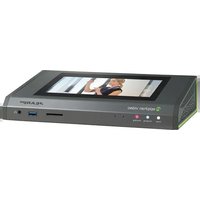


- Epiphan Pearl-2 Pearl-2 Rackmount Pearl-2 Rackmount Twin
- Terms and conditions
- LIMITATION OF LIABILITY
- Thank you for choosing Epiphan!
- Product feedback
- Specifications
- Warranty
- Technical support
- What's new in release 4.4.1?
- What's fixed
- AV Synchronization
- Custom Wowza streaming option
- AV.io SDI capture card recognition
- Hot plugged 1080i source recognition
- Table of contents
- PART 1: Setup 48
- PART 5: Maintenance 417....
- Start here
- About this Guide
- What is Pearl-2?
- Using Pearl-2 effectively
- Channel name Status Video source Audio source Stream Bitrate Actual bitrate Frame size FPS / Actual FPS Port
- AV inputs
- What's in the Box?
- Front and back view
- Pearl-2
- Pearl-2 Rackmount
- Pearl-2 Rackmount Twin
- Tech specs
- About 4K on Pearl-2
- Feature add-ons
- Quick start
- Get started quickly with auto channels:
- To view the auto channels:
- Record the Channel
- What's Next?
- Epiphan Live
- Accessing Epiphan Live
- Connecting to Epiphan Live directly using your computer's web browser
- Connecting to Epiphan Live directly using your mobile device
- Connecting to Epiphan Live from the Admin panel
- Connecting to the Admin panel from Epiphan Live
- Streaming, recording and monitoring using the Dashboard interface
- Understanding the Dashboard interface
- Configuring Dashboard panels for visual confidence monitoring
- Monitoring video and audio sources
- Video sources
- Configure the video input list
- View video source details
- Audio sources
- Read the VU meter
- Configure the audio input list
- Configuring and monitoring video outputs
- View video output details
- Configure video outputs
- To configure video outputs:
- Controlling streaming and recording using Epiphan Live
- Stream and record channels
- Record a Admin panel Recorder
- Live switching using the Switcher interface
- Understanding the Switcher interface
- Switching while live streaming and recording
- Your Recordings
- PART 1: Setup
- Topics covered:
- Rackmount installation
- The Admin panel
- Connect to the Admin panel
- Connect using the touch screen
- Connect via DNS-based service discovery
- Connect via the Epiphan discovery utility
- Connect via persistent static IP address
- User administration
- User types and privileges
- Admin
- Operator
- Viewer
- Current user
- User privileges
- Set or change user passwords
- Remove user passwords
- Overcome lost passwords
- Configure LDAP
- Change the logged-in user
- Restrict viewers by IP address
- IP restriction examples
- Allow list with distinct IP addresses
- Allow list with a range of IP addresses
- Allow list with a range of IP addresses and one or more specific IP addresses
- Deny list with distinct IP addresses
- Allow list with a range of IP addresses, distinct IP addresses and an exception
- Deny list with a range of IP addresses
- Pearl-2's touch screen
- Touchscreen overview
- No Channels
- Preview is disabled
- View system information
- Channel monitoring
- Individual channel monitoring
- Grid-view channel monitoring
- Pearl-2's audio jack
- Audio monitoring
- Adjust audio monitoring volume
- Audio VU meter
- Control recording of individual channels
- Control streaming of individual channels
- To stop streaming:
- One Touch streaming and recording control
- This topic covers:
- Understand and use One Touch control
- Specify channels and recorders for One Touch recording
- Topics include:
- Specify channels for One Touch recording
- To specify channels for single touch recording:
- Specify recorders for One Touch recording
- Specify channels for One Touch streaming
- Customize how One Touch control is displayed
- View AFU status
- Configure the touch screen
- Disable (or enable) the touch screen
- Hide (or show) channel previews on the touch screen
- Disable (or enable) system status on the touch screen
- Click Apply.
- Block (or allow) configuration functions from the touch screen
- Block (or allow) recording, streaming and switching from the touch screen
- Set touch screen timeout
- Configure touch screen PIN security code
- Add-ons overview
- Shop now
- Firmware Upgrade
- Install purchased add-ons
- 4K feature add-on
- List of features
- Purchase button
- Activation indicator
- Checking availability of add-ons
- Available for purchase
- 4K feature add-on Purchase
- 4K feature add-on √ Activated
- This site says...
- Available for installation and activation
- Available for use
- Current list of add-ons
- Activate purchased add-ons
- Purchase and install add-ons
- Configure network settings
- Verify IP Address and MAC address via the touch screen
- Verify IP address and MAC address via the Admin panel
- IP Configuration for eth0
- Configure DHCP
- Configure a static IP address
- Label Description/Options
- Tether to a mobile network
- Network ports used by Pearl-2
- Perform network diagnostics
- Network Diagnostics
- Configuration presets
- Configuration presets overview
- Configuration presets in action
- Internal network and AFU preset
- Conference network and AFU preset
- Conference breakout session and keynote presets
- Summary
- Configuration groups
- Create a configuration preset
- Export and import configuration presets
- Download a configuration preset
- Import a configuration preset
- Apply a configuration preset from the Admin panel
- Apply a configuration preset using the touch screen
- Apply the Factory default configuration preset
- Update a configuration preset
- Delete a configuration preset
- Configuration preset considerations
- Channel and recorder index number behavior
- Recording and streaming states
- Recorded files (in channels and recorders)
- Deleting channels
- Branding content
- Configuration presets are not user profiles
- Touch screen considerations
- Configure date and time
- Verify date and time via the touch screen
- Verify date and time settings
- Configure synchronized time (NTP, PTP v1 and RDATE)
- Configure the date and time manually
- Change the time zone
- Configure a local NTP server
- Video output ports
- Show a channel on the video output port
- Show a source on the video output port
- Select a resolution for the video output port
- Preview the video output port
- View the video output port status
- Disable the video output port
- Disable or enable the audio on the video output port
- Configure the audio meter
- Rename a video output port
- PART 2: Capture
- What is a channel?
- Channels
- Use the automatic channels Auto A and Auto B
- Know which signal is used for Auto-A or Auto-B
- Configure auto channels
- Create a simple channel
- Create a custom channel
- Custom channel layout editor
- Layout selector
- Visual channel layout editor
- Audio source selector and save button
- Custom channel examples
- Layout example Description
- Create a custom channel or layout
- Important note for channels with multiple layouts
- Add a video source (custom channel)
- A note about item positioning and sizing
- To use the mouse:
- To use the keyboard:
- Using percents:
- Using pixels:
- Add an audio source (custom channel)
- Custom crop a source
- Configure chroma keying
- Performance considerations
- What is upstream chroma keying?
- What is downstream chroma keying?
- Set up chroma key for a green screen video source
- Cropping the green screen video source helps optimize the performance of Pearl-2.
- Add chroma key titler effects using Microsoft Powerpoint slides
- Add external titler software effects to Pearl-2
- To upload an image
- Add an image (custom channel)
- Add a text overlay (custom channel)
- Custom overlay text (static)
- Custom overlay text (dynamic)
- Set the background color (custom channel)
- Resize and position layout items using percents or pixels (custom channel)
- Resize layout items
- An important consideration when resizing layout items
- Position layout items
- Example 1: horizontal positioning using percents
- Example 2: vertical positioning using pixels
- Rename a layout (custom channel)
- If you're using the touch screen for Live video mixing / switching
- To rename a layout:
- Delete, move, or duplicate a layout (custom channel)
- Reorder layouts
- Delete layouts
- Duplicate layouts
- Delete an uploaded image
- Configure encoding
- Configure video codec
- Configure frame size
- For example:
- Fine tune stream settings
- Configure audio codec
- Codec and file format compatibility
- Multi-Encoding
- Follow these steps:
- Add channel metadata
- Remove metadata from a channel
- Preview a channel
- Preview a channel from the Info page
- Pearl-2 B7E5C813 info
- Firmware
- Hardware
- Preview a channel from the Status page
- Preview all channels at once
- Rename a channel
- To rename a channel:
- Duplicate a channel
- Delete a channel
- Live video mixing / switching
- Switching / mixing using the touch screen
- Switching / mixing using the Admin panel
- Switching / mixing using Epiphan Live
- What is a source?
- Connect a source
- Connect an RTSP source
- Create an RTSP loopback
- List of tested RTSP-based IP cameras
- List of fully supported Web cameras
- Table 39 List of tested Web cameras
- Connect an AV.io video grabber
- Preview a source
- Configure a source
- DVI and HDMI signals
- SDI signals
- USB signals
- USB-A
- Status
- Settings
- Video
- "No signal" image
- Audio
- RTSP sources
- Add a No Signal image to a source
- Before you can specify a custom no signal image for a source, you must upload it following the procedure To upload an image.
- Rename a source
- Adjust audio gain (analog audio) and delay
- Audio Analog-A Audio
- Confirm audio levels
- Troubleshoot capture
- Remove black bars (matte) from the video
- Match the output frame size to the aspect ratio of the source signal
- Stretch the image
- Force the capture card to use a specific EDID
- Upload a new EDID
- Restore factory default EDID
- Unstretch the output video
- Remove the combing effect on images
- PART 3: Stream
- What is streaming?
- Streams for viewers:
- Stream to a server:
- Stream to a media player:
- Choose a streaming option
- Supported streaming formats
- Stream info
- Stream to viewers
- Stream content using HTTP or RTSP
- Configure HTTP and RTSP streaming ports
- Stream content using HLS (HTTP Live Streaming)
- Send stream URLs to viewers
- View the Flash stream
- View your broadcast using the View link on the Info menu
- View your broadcast using the Live broadcast link on the Status page
- Viewing with a web browser
- Viewing with a media player (RTSP)
- Disable (and enable) streams for viewers
- Restrict access to streams for viewers
- Stream to a server
- Stream to a CDN
- Start and stop streaming to a CDN
- Start and stop streaming using the Admin panel
- Start and stop streaming using the touch screen's channel monitoring view
- Start/stop streaming using One Touch control
- Start and stop streaming using Epiphan Live
- To stream content to a CDN using RTSP announce
- To stream content to a CDN using RTMP push
- Stream to a CDN using an XML profile
- Stream to Wowza Streaming Cloud
- Connections
- Stop streaming to the Wowza Streaming Cloud
- Stream to Original Livestream
- Stream content using multicast
- MPEG-TS streams using RTP/UDP push
- MPEG-TS streams using UDP push
- Multicast streaming using RTP/UDP
- Viewing with Session Announcement Protocol (SAP)
- Stream to a media player or smart TV
- Stream content using UPnP
- Enable UPnP
- Step 1: Enable UPnP at the device level
- Step 2: Enable UPnP for channels and/or recorders
- For channels (recorded files):
- Disable UPnP
- Viewing with UPnP
- Live streams
- Recorded files
- Play directly to a media player
- Auto-restart playback to a UPnP device
- Change UPnP device name
- Samples of stream settings
- Streaming video content
- Streaming slide content
- PART 4: Record
- What is a recording?
- Recording basics
- Record a channel via the Admin panel
- Record channels and recorders (using One Touch control)
- Record a channel via Epiphan Live
- Record a channel via the touch screen
- To start recording:
- To stop recording:
- Configure recording file size and type
- Recorder Setup
- Restart recording
- Recorders
- Add a recorder
- Change the channels recorded by a recorder
- Record with a recorder (using the admin panel)
- Record a recorder (using One Touch control)
- Record a recorder (using Epiphan Live)
- Rename a recorder
- Duplicate a recorder
- Delete a recorder
- View list of recorded files
- Otherwise:
- Download recorded files manually
- Concatenate files
- Extract tracks from a recording
- Rename recorded files
- Delete recorded files manually
- File and recording transfer
- Automatic file upload (AFU) overview
- Choose files to include in AFU
- Enable AFU and set parameters
- Automatic File Upload
- AFU to an FTP server
- AFU using RSync
- AFU using CIFS
- AFU using SCP
- AFU to a secure FTP server
- AFU to Amazon Web Server (AWS)
- AFU to a WebDav server
- AFU or copy to USB
- AFU to a USB drive
- One-time copy/move of all recorded files to USB drive
- Manually copy recorded files to USB drive
- View available USB storage space
- Safely eject the USB drive
- View the AFU log
- Manage the AFU queue
- Access the AFU queue
- View content in the AFU queue
- Delete content in the AFU queue
- Local FTP server
- Configure the local FTP server
- Using the local FTP server
- PART 5: Maintenance
- Power down and system restart
- Restarting the device via the Admin panel
- Shutting down the device via the Admin panel
- Shutting down the device manually
- Save and restore device configuration
- Perform factory reset
- Restore factory configuration via the Admin panel
- Factory reset
- Check for firmware updates
- Install firmware
- Install firmware directly from the Admin panel:
- Firmware Update
- Firmware Update Error
- Install firmware from a file
- Support
- To contact Epiphan support:
- Download logs and "allinfo"
- Configure remote support
- Disable remote support
- To disable remote support:
- Storage disk maintenance
- Check disk storage space
- To check disk storage space:
- Check disk storage space via the touch screen
- Schedule disk check
- Perform disk check
- Disk check in progress
- Third party integration
- Control with RS-232 / serial port
- Connect and configure the RS-232 cable
- Control Pearl-2 with RS-232
- RS-232 / Serial port command examples
- Control with HTTP commands
- HTTP command syntax
- Multiple requests at once
- Third party applications like wget
- HTTP command examples
- To start recording on recorder 2:
- Global variable HTTP command syntax for custom layouts
- Important considerations for global custom layout variables
- Set variables – syntax and example
- Get variables – syntax and example
- Configuration keys for third party APIs
- System-level settings keys (read-only)
- System-level settings keys (read/write)
- System-level custom layout keys (read/write)
- Touch screen settings keys (read/write)
- Recording configuration keys
- HTTP server configuration keys
- IP-based access control configuration keys
- UPnP configuration keys
- Broadcast configuration keys
- Channel encoder configuration keys
- Channel layout configuration keys
- Audio configuration keys
- Stream publishing configuration keys
- RTSP Announce configuration keys (Publish type 2)
- RTP/UDP configuration keys (Publish type 3)
- MPEG-TS configuration keys (Publish types 4 and 5)
- RTMP push configuration keys (Publish type 6 and 7)
- Livestream configuration keys (Publish type 8)
- Content metadata configuration keys
- PART 6: Troubleshooting
- Limitations and known issues
- Affecting encoding
- Affecting streaming and recording
- Affecting the Admin panel
- Affecting Epiphan Live
- Affecting video output ports
- Affecting USB devices
- Affecting other areas
- Previous releases and features
- Release 4.4.0
- Release 4.3.0
- Release 4.2.0
- Release 4.0.1
- Software license
- Epiphan Systems Inc.
- Definitions: In this Agreement:
- FOR THE DISCLAIMER OF REPRESENTATIONS, WARRANTIES AND CONDITIONS AND LIMITATION OF LIABILITY, NEITHER LICENSOR NOR ANY OF ITS AFFILIATES OR ITS OR THEIR LICENSORS, SUPPLIERS, RESELLERS OR DISTRIBUTORS WOULD GRANT THE RIGHTS GRANTED IN THIS AGREEMENT.
- Environmental Information
- Important Safety Warnings
- FCC & CE Compliance Statement
- FCC€
- Other Jurisdictional Issues
- Submissions to Epiphan and Affiliated Servers
- Third Parties and Links to Third-Party Web Sites
- Miscellaneous
- Enforcement of Terms and Conditions
Brand : Epiphan
Model : Pearl-2
Category : Processor