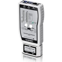
TC-NT3 - Multimeter TRENDNET - Free user manual and instructions
Find the device manual for free TC-NT3 TRENDNET in PDF.


| Product Type | Digital Multimeter |
| Brand | TRENDnet |
| Model | TC-NT3 |
| Dimensions | 150 x 80 x 30 mm |
| Weight | 200 g (including batteries) |
| Power Supply | 2 x AA batteries (1.5V) |
| DC Voltage Range | 200 mV to 600 V |
| AC Voltage Range | 2 V to 600 V |
| DC Current Range | 200 µA to 10 A |
| Resistance Range | 200 Ω to 20 MΩ |
| Capacitance Range | 2 nF to 200 µF |
| Frequency Range | 20 Hz to 20 kHz |
| Temperature Range | -20°C to 1000°C (with thermocouple) |
| Functions | AC/DC voltage, AC/DC current, resistance, continuity, diode test, capacitance, frequency, temperature, hFE transistor test |
| Display | LCD, 3.5 digits (2000 counts) |
| Safety Rating | CAT II 600V |
| Overload Protection | Yes, fuse protection for current ranges |
| Auto Power Off | Approx. 15 minutes |
| Accessories Included | Test leads, thermocouple, batteries, user manual |
| Maintenance | Clean with a dry cloth; avoid water and solvents |
| Storage Conditions | Temperature: -10°C to 50°C, humidity <80% |
| Spare Parts Available | Test leads, fuses, batteries |
Frequently Asked Questions - TC-NT3 TRENDNET
User questions about TC-NT3 TRENDNET
0 question about this device. Answer the ones you know or ask your own.
Ask a new question about this device
Download the instructions for your Multimeter in PDF format for free! Find your manual TC-NT3 - TRENDNET and take your electronic device back in hand. On this page are published all the documents necessary for the use of your device. TC-NT3 by TRENDNET.
USER MANUAL TC-NT3 TRENDNET
Getting to know TC-NT3
Transmitter
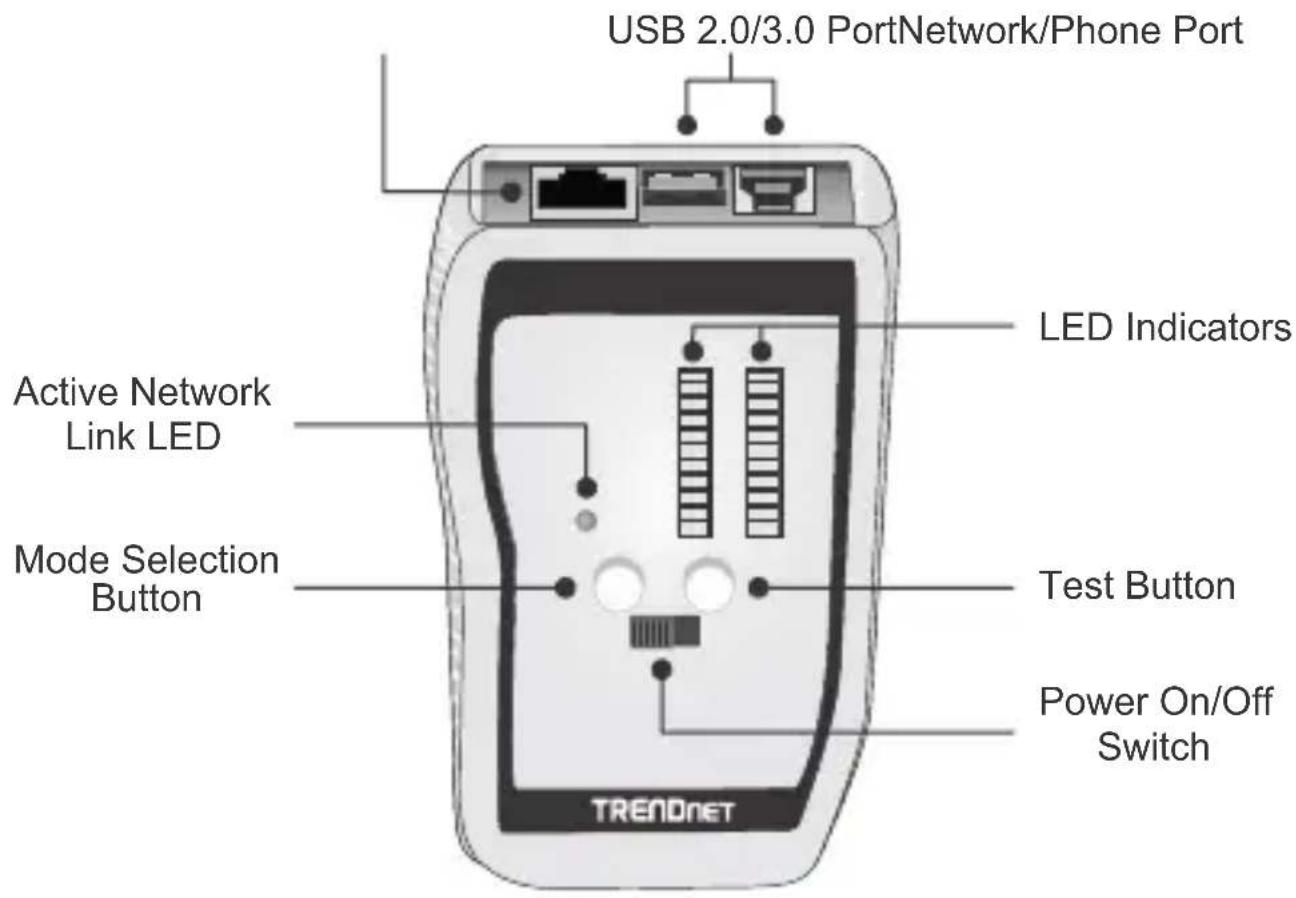
Remote Terminator

How to Separate the Transmitter and Terminator
Slide the bottom of the TC-NT3 Remote Terminator towards the back of the TC-NT3 Transmitter.

natural_image
Illustration of a TRENCHET device with two ports and a central display, shown with bidirectional arrows indicating data flow (no text or symbols on the device itself)Warning and Caution
- This device is designed to be used on a cabling system without voltage. Do not connect the TC-NT3 to any live circuits, lines or outlets. Doing so may damage the TC-NT3 and equipment.
- Disconnect cables from all electronic equipment with voltage before testing. Failure to do so may damage the TC-NT3.
Install / Replace the Battery (9V Alkaline battery is not included)
- Change the battery if the Battery Low (B/L) LED is on.
- Slide the battery cover off the TC-NT3 transmitter.
- Connect and insert the battery.
- Slide the battery cover back on to the TC-NT3 remote transmitter.
Network/Phone and USB Cable Test
- Connect one end of a network, phone or USB cable to the Network / Phone (RJ45/12) or USB port on the Transmitter. Connect the other end of the network, phone or USB cable to the Remote Terminator.
- Switch the power button to the On position; it will perform a Quick Test by default.
Quick Test Mode
Quick Test mode quickly identifies the type of cable. If a test cable pin out matches the pin out of a standard cable, the TC-NT3 Transmitter will indicate this by lighting up the corresponding LED. The default mode on TC-NT3 is set to Quick Test mode. You can also press the Test button 3 times to enter to Quick Test mode.
Note: Quick Test mode does not include shielded testing. If you would like to test a shielded cable, please use Auto/Step or Learn mode.
Learn Mode
Learn mode allows the TC-NT3 to memorize and test large quantities of custom shielded cables with any pin out or configuration. It displays PASS or FAIL.
- Before using Learn mode, a known good cable is required.
- Connect one end of a cable to the TC-NT3 Transmitter and the other end to the Remote Terminator.
- Power on the TC-NT3. Press the Mode button one time or until the Learn mode LED is lit.
- After the cable recording has completed, the Pass and ID LED will be lit. If the Fail LED has lit, Learn mode has failed. Please press the Mode button again to retest the cable until the Pass LED is lit.
- If a new cable pin out is the same as the learned cable, the TC-NT3 will display the Pass and ID LED.
- If a new cable pin out is different from the learned cable, the TC-NT3 will display the Fail and ID LED.
- All stored pin outs in Learn mode will be erased after the TC-NT3 is power off.
Auto Scan Mode/Step Mode
Auto Scan mode is used to quickly test pin configurations. Step mode allows you to manually verify each pin one at a time.
- Connect one end of a cable to the TC-NT3 Transmitter and the other end to the Remote Terminator.
- Power on the TC-NT3 then press the Test button once. The AUTO/STEP LED will blink in to indicate Auto mode. The pin LEDs will indicate pin status.
- To change to manual testing, press the Mode button once to enter Step mode. The Auto/Step LED becomes solid to indicate Step mode.
- Press the Mode button again to move to the next pin to test.
Shield Testing
In Auto/Step mode, it will automatically test for shield integrity. If the shield LEDs (TX and RX) are lit, the cable is shielded. If the shield RX LED is off, the cable is not shielded or the shielding has failed.
Coaxial Cable Testing
Coaxial testing is available for Auto/Step and Learn Mode.
- Use the included RJ45 to F female adapter to test coaxial cable.
- The test results will show on pin 4 and pin 5. Pin 4 indicates the center pin and pin 5 indicates the shield.
Blink Hub/LINK/Tone Mode
Blink Hub mode is a quick way to identify if a network cable or outlet is connected to an active network such as a hub, switch or router. Do not test a cable connected to a live telephone system or AC/DC circuits (PoE injector/switch) in this mode. Doing so will damage the TC-NT3.
- Power on the TC-NT3. Press the Test button 2 times to go into Blink Hub mode. The Blink Hub LED will blink to indicate it is in Blink Hub mode.
- Connect a cable to the TC-NT3 transmitter. If you are testing a network wall outlet, connect to it by using the included patch cable.
- The TC-NT3 transmitter will send a link pulse if an Ethernet link is active on the cable or outlet. The tester begins blinking and the LED on the corresponding port of the Hub or switch will also blink for easy identification.
- If there is no active connection detected, the Active Link LED will be off.
Note: Hub Blink mode also generates a tone. Hub Blink mode can only be used on non-shielded cables. Shielded cables will cause a misread and activate the Active Link LED without an active connection.
Tone Tracing (Required TC-TP1, sold separately)
Trace a tone using the TC-TP1 to quickly isolate or locate a cable. When tracing a shielded cable, the Active Link LED will blink or light when using a Hi tone or remain solid in a Lo tone.
- Power on the TC-NT3.
- Press the Test button two times to enter Blink Hub/Tone Mode.
- Connect a cable to TC-NT3 transmitter.
- Use the TC-TP1 to locate and trace the tone (Please refer the TC-TP1 Quick Installation Guide for detailed usage).
- Press the Mode button to select Hi or Lo tone.
- Use the included RJ-45 to F adapter for tracking coaxial cables.
| Cable Type | Quick Test | Learn Mode | Cable LED Indicator |
| USB 3.0Transmitter: type BTransmitter: type A | TX: 1 2 3 4 5 6 7 8 9RX: 1 2 3 4 5 6 7 8 9 | TX: 1 2 3 4 5 6 7 8 9 S RX: 1 2 3 4 5 6 7 8 9 S | USB 3.0 |
| USB 3.0Transmitter: type ATransmitter: type A | TX: 1 2 3 4 5 6 7 8 9RX: 1 2 3 4 8 9 7 5 6 | TX: 1 2 3 4 5 6 7 8 9 S RX: 1 2 3 4 8 9 7 5 6 S | USB 3.0 |
| USB 2.0Transmitter: type ATransmitter: type A | TX: 1 2 3 4RX: 1 2 3 4 | TX: 1 2 3 4 S RX: 1 2 3 4 S | USB 2.0 |
| USB 2.0Transmitter: type BTransmitter: type A | TX: 1 2 3 4RX: 1 2 3 4 | TX: 1 2 3 4 S RX: 1 2 3 4 S | USB 2.0 |
| Crossover(PC to PC) | TX: 1 2 3 4 5 6 7 8RX: 3 6 1 4 5 2 7 8 | CROSS | |
| UTP | TX: 1 2 3 4 5 6 7 8RX: 1 2 3 4 5 6 7 8 | T568 A/B | |
| STP | TX: 1 2 3 4 5 6 7 8RX: 1 2 3 4 5 6 7 8 | TX: 1 2 3 4 5 6 7 8 S RX: 1 2 3 4 5 6 7 8 S | T568 A/B |
| USOCStraight Thru | TX: 1 2 3 4 5 6 7 8RX: 1 2 3 4 5 6 7 8 | T568 A/B | |
| USOC 8Reversed | TX: 1 2 3 4 5 6 7 8RX: 8 7 6 5 4 3 2 1 | USOC 8 | |
| USOC 6Reversed | TX: 2 3 4 5 6 7RX: 7 6 5 4 3 2 | USOC 6 | |
| USOC 4Reversed | TX: 3 4 5 6RX: 6 5 4 3 | USOC 4 | |
| USOC 2Reversed | TX: 4 5RX: 5 4 | USOC 2 | |
| Coaxialwith RJ-45 to F Adapter | TX: 4 5 pin 4 = center Pin RX: 4 5 pin 5 = shielding | ||
| The TX/RX LED is based on standard cable types. If you are using custom made cables, the TX/RX LEDs might not display as listed on the table.If more than one LED from the same row is lit, it indicates a short.If an LED is skipped, this may indicate an open wire. | |||
Manufacturer's Name and Address
TRENDnet, Inc.
20675 Manhattan Place
Torrance, CA 90501 USA

Product Information:
Model Number: TC-NT3
Product Name: VDV & USB Cable Tester
Trade Name: TRENDnet
TRENDnet hereby declare that the product is in compliance with the essential requirements and other relevant provisions under our sole responsibility.
EMC
EN 55011: 2009 + A1: 2010 Group 1 (Class B)
EN 61000-3-2: 2006 + A2: 2009
EN 6100-3-3: 2013
EN 61326-1: 2013
EN 61326-2-1: 2013
EN 61326-2-2: 2013
This product is herewith confirmed to comply with the Directives.
Directives:
EMC Directive 2004/108/EC
RoHS Directive 2011/65/EU
REACH Regulation (EC) No. 1907/2006
Person responsible for this declaration.
Place of Issue: Torrance, California, USA
Date: October 22, 2014
Name: Sonny Su
Title: Director of Technology
Signature:

Manufacturer's Nom et Adre
TRENDnet, Inc.
20675 Manhattan Place
Torrance, CA 90501 USA

Détails du produit:
Modèle: TC-NT3
Directive CEM 2004/108/CE
Directive RoHS 2011/65/UE
REACH Réglement (CE) N° 1907/2006
Date: October 22, 2014
Lieu de déliv
Nom: Sonny Su
Signature:
Position: Director of Technology
Limited Warranty
TRENDnet warrants its products against defects in material and workmanship, under normal use and service, for the following length of time from the date of purchase. Warranty: 1 year limited warranty (When Applicable: 1 year warranty for power adapter, power supply, and cooling fan components.) Visit TRENDnet.com to review the full warranty policy, rights, and restrictions for this product.
Garantie Limitée
This device can be expected to comply with Part 15 of the FCC Rules provided it is assembled in exact accordance with the instructions provided with this kit.
Operation is subject to the following conditions:
(1) This device may not cause harmful interference
(2) This device must accept any interference
received including interference that may cause undesired operation.


Waste electrical an electronic products must not be disposed of with household waste. Please recycle where facilities exist. Check with your Local Authority or Retailer for recycling advice.
Note
The Manufacturer is not responsible for any radio or TV interference caused by unauthorized modifications to this equipment. Such modifications could void the user's authority to operate the equipment.
Advertencia
If you have any questions regarding the product installation, please contact our Technical Support.
Toll free US/Canada: 1-866-845-3673
Regional phone numbers available at www.trendnet.com/support
Product Warranty Registration
Please take a moment to register your product online. Go to TRENDnet's website at: http://www.trendnet.com/register
Copyright © 2014. All Rights Reserved. TRENDnet.
- Getting to know TC-NT3
- Transmitter
- Remote Terminator
- How to Separate the Transmitter and Terminator
- Warning and Caution
- Install / Replace the Battery (9V Alkaline battery is not included)
- Network/Phone and USB Cable Test
- Quick Test Mode
- Learn Mode
- Auto Scan Mode/Step Mode
- Shield Testing
- Coaxial Cable Testing
- Blink Hub/LINK/Tone Mode
- Tone Tracing (Required TC-TP1, sold separately)
- Manufacturer's Name and Address
- Product Information:
- EMC
- Directives:
- Manufacturer's Nom et Adre
- Limited Warranty
- Garantie Limitée
- Note
- Advertencia
- Product Warranty Registration
Brand : TRENDNET
Model : TC-NT3
Category : Multimeter