
SPEEDTOUCH HOME - Modem/Router ALCATEL-LUCENT - Free user manual and instructions
Find the device manual for free SPEEDTOUCH HOME ALCATEL-LUCENT in PDF.

| Product type | ADSL Modem/Router |
| Brand | Alcatel-Lucent |
| Model | Speedtouch Home |
| Dimensions (W x D x H) | 20 x 14 x 4 cm |
| Weight | 300 g |
| Power supply | External power adapter 12 V DC, 0.5 A |
| Power consumption | 6 W maximum |
| Network interface | 1 ADSL port (RJ11), 4 Ethernet 10/100 ports (RJ45) |
| ADSL standards | ADSL, ADSL2, ADSL2+ |
| Main functions | ADSL modem, router, NAT, DHCP, firewall, VPN pass-through |
| Supported protocols | PPPoE, PPPoA, IPoA, RFC 1483 |
| Configuration | Web interface via browser (192.168.1.1) |
| Security | Integrated firewall, MAC filtering, SPI |
| Maintenance and cleaning | Clean with a soft dry cloth. Do not use solvents. |
| Operating temperature | 0 °C to 40 °C |
| Operating humidity | 20% to 80% (non-condensing) |
| Spare parts and repairability | Power adapter, RJ11 cable, Ethernet cable. Professional repair recommended. |
| General information | Class B digital device compliant with Canadian radio interference regulations. |
Frequently Asked Questions - SPEEDTOUCH HOME ALCATEL-LUCENT
User questions about SPEEDTOUCH HOME ALCATEL-LUCENT
0 question about this device. Answer the ones you know or ask your own.
Ask a new question about this device
Download the instructions for your Modem/Router in PDF format for free! Find your manual SPEEDTOUCH HOME - ALCATEL-LUCENT and take your electronic device back in hand. On this page are published all the documents necessary for the use of your device. SPEEDTOUCH HOME by ALCATEL-LUCENT.
USER MANUAL SPEEDTOUCH HOME ALCATEL-LUCENT
Short Title CD-UG STHome
All rights reserved. Passing on and copying of this document, use and communication of its contents not permitted without written authorization from Alcatel.
Contents
1 Speed Touch Installation Guide 11
1.1 Get Acquainted with your Speed Touch 12
1.2 Speed Touch Installation 16
1.2.1 What you Need 17
1.2.2 STHome Wiring 18
1.2.3 STHome Power On/Off Behaviour 20
2 Speed Touch Configuration Guide 21
2.1 Check your PC Configuration 22
2.2 Check your SP's Service Offerings 23
2.3 Speed Touch Configuration 24
2.3.1 STHome Web Interface Access 25
2.3.2 STHome Packet Services 27
2.3.3 Transparent Bridging Packet Service Configuration 29
2.3.4 Bridged PPPoE Packet Service Configuration 30
2.3.5 PPPoA-to-PPTP Relaying Packet Service Configuration 31
2.3.6 Advanced STHome Configuration 33
3 Configuration - Bridging and Bridged PPPoE 37
4 Configuration - PPPoA-to-PPTP Relaying 39
4.1 MS Windows 98 Dial-Up Networking 40
4.1.1 Create a New Dial-Up Networking Icon 41
4.1.2 Opening and Closing a Dial-Up Session 44
4.2 PPPoA/PPTP Configuration 46
5 Networking - ATM 49
5.1 The ATM Packet Switching Technology 50
5.2 The Speed Touch Phonebook 52
5.3 AutoPVC 54
6 Networking Services - IP, DHCP and DNS 55
6.1 Packet Services and IP 56
6.1.1 Transparent Bridging 57
6.1.2 PPPoA-to-PPTP Relaying 58
6.2 Speed Touch Addresses 59
6.3 Speed Touch DHCP 61
6.4 Speed Touch DNS 64
7 Maintenance - Speed Touch Software 67
8 Maintenance - Speed Touch Password 71
9 Maintenance - Speed Touch To-Defaults 73
9.1 Ping-of-Life 74
9.2 Speed Touch Reset 76
9.2.1 Browse-to-Defaults 77
9.2.2 Ping-to-Defaults 78
9.2.3 Switch-to-Defaults 79
Abbreviations 83
AppendixA Speed Touch Troubleshooting 85
AppendixB Speed Touch Specifications 87
AppendixC Speed Touch Default Assignments 93
AppendixD Safety and Agency Regulatory Notices 97
Alcatel Speed Touch Home
Introduction

The Alcatel Speed Touch™ Home DSL modem provides high-speed access to the Internet for fastidious home users.
For optimal Local Area Network (LAN) performance the Alcatel Speed Touch™ Home includes a comprehensive set of features, as there are static IP routing, a DHCP server and DNS server.
ADSL/POTS and ADSL/ISDN
Two variants of Alcatel's Speed Touch™ Home Asymmetric Digital Subscriber Line (ADSL) modems exist:
An ADSL/POTS variant connecting to an analog POTS() line
An ADSL/ISDN variant connecting to a digital ISDN (^*) line (compliant to ETSI standards)
() Plain Old Telephone Service (POTS)
(^*) Integrated Services Digital Network (ISDN)
Terminology
For readability, the Alcatel Speed Touch™ Home will be referred to as STHome in this User's Guide.
Safety instructions
Prior to connecting the Alcatel Speed Touch™ Home, read the Safety Instructions in appendix D.

CAUTIONWARNING
The following words and symbols mark special messages throughout this document:
WARNING: indicates that failure to follow the directions could cause bodily harm or loss of life.
CAUTION: indicates that failure to follow the directions could result in damage to equipment or loss of information.
Trademarks
The following trademarks are used in this document:
Speed Touch™ is a trademark of the Alcatel Company
Netscape® and Netscape Navigator® are registered trademarks of Netscape Communications Corporation
WindowsTM and Internet ExplorerTM are trademarks of Microsoft Corporation
Apple® and Mac®OS are registered trademarks of Apple Computer Inc.
- UNIX® is a registered trademark of UNIX System Laboratories, Inc.
Ethernet™ is a trademark of Xerox Corporation.
Other products may be trademarks or registered trademarks of their respective manufacturers.
Service Provider
For readability, the term Service Provider (SP) will be used to designate all organizations which provide either DSL connectivity, Internet access or Corporate access, for example an Internet Service Provider (ISP).
PC, workstation, terminal, ...
For readability, PC will refer to all involved computer devices which are able to interact with the STHome, i.e. Personal Computer (PC), Macintosh computer, workstation, (remote) terminal, etc.
Disclaimer
All examples throughout this User's Guide refer to :
"Net 10" IP addresses for local network configurations
VPI 0 or VPI 8 to identify the Virtual Path (VP) on the DSL line. However, your SP might prefer other values.
User's Guide updates
Due to the continuous evolution of the Alcatel DSL technology, existing products are regularly upgraded. Alcatel documentation changes accordingly.
For more information on the newest technological changes and documents, please consult the Alcatel web site at following Uniform Resource Locator (URL):
http://www.alcatel.com
http://www.alcateldsl.com
Alcatel
Speed Touch™Home
Quick Guide
1 Speed Touch Installation Guide
Aim of this Quick Guide Use this chapter to quickly connect your STHome.
In this chapter
| Topic | See |
| Get Acquainted with your STHome | 1.1 |
| STHome Installation | 1.2 |
1.1 Get Acquainted with your Speed Touch
Delivery check
Check your STHome package for the following items:
The Alcatel Speed Touch™ Home
1 Power supply adapter with 2m (6.56ft.) connecting cable
2m Cat.5 straight-through Ethernet/ATMF cable (RJ45/RJ45)
2m DSL cable (RJ11/RJ11, RJ14/RJ14)
This User's Guide, either in hard copy format or on CD-ROM.
Damaged or missing items
In the event of damaged or missing items, contact your local product dealer for further instructions.
Other materials
Your STHome shipping carton may also include release notes, safety and conformity declarations and other materials.
The STHome
The STHome is presented in a slim line box:

Five front panel LEDs
The STHome is equipped with 5 LEDs on its front panel, indicating the state of the device:
| Indicator | Description | ||
| Name | Color | State | |
| LAN | Green | Flashing | Data is flowing from/to the Ethernet port(s). |
| Off | No activity on the Ethernet port(s). | ||
| Line TX | Green | Flashing | ATM cells are being sent over the DSL line. |
| Off | No transmission activity. | ||
| Line RX | Green | Flashing | ATM cells are being received via the DSL line. |
| Off | No reception activity. | ||
| Line Sync | Green | Flashing | During initialization of the DSL line. |
| On | DSL line synchronization achieved. | ||
| PWR/Alarm | Green | On | Power on, normal operation. |
| Amber | On | Power on, start-up failed. | |
| Red | Flashing | Power on, POST(*) pending. | |
| On | Power on, POST(*) failed. | ||
(*) Power On Self Test (POST)
STHome models
Two STHome models can be identified:
The single 10Base-T Ethernet port STHome model:
The dual port STHome model with both 10Base-T Ethernet port and ATM Forum - 25.6 Mbps (ATMF-25.6) port:
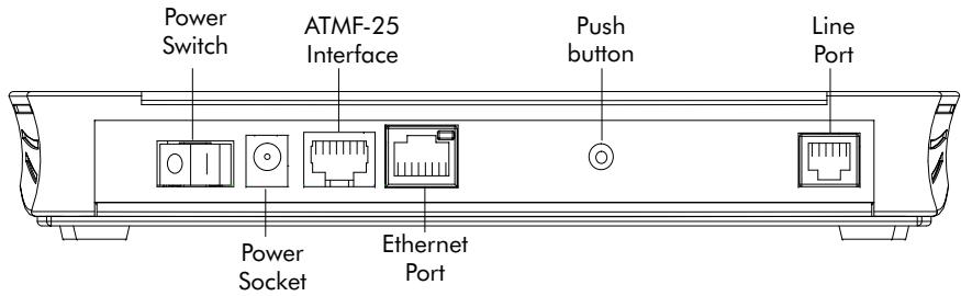
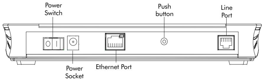
Back panel parts
The ADSL/POTS or ADSL/ISDN "Line" port
The "Defaults" push button
The "10Base-T MDI-X" Ethernet port
The optional "ATM-25.6" port
The "DC" power socket
The power switch.
See section 1.2 for more information.
ADSL/POTS and ADSL/ISDN
Two Asymmetric Digital Subscriber Line (ADSL) STHome variants exist:
An ADSL/POTS STHome connecting to an analog POTS(*) line
An ADSL/ISDN STHome connecting to a digital ISDN** line.
() Plain Old Telephone Service (POTS)
() Integrated Services Digital Network (ISDN)
Identify your variant
Use only the STHome variant which is appropriate for the DSL service delivered to your local premisses.
Therefore, firstly identify your STHome via the marking label on the bottom:
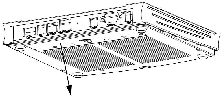


CPYYWWNNNNN


MODEL NUMBER:
3EC 18704BC AA01
Speed Touch Home POTS Network Terminator
In the figure above, an example is provided of the marking label for an ADSL/POTS STHome variant.
Note: For ADSL/ISDN variants, the description POTS is replaced by ISDN.
The North-American market uses exclusively ADSL/POTS variants.
The marking label is similar to the example below:


CP992300XXX
Speed Touch Home NT Tested to Comply with

FCC rules Part 15 and Part 68
FOR HOME OR OFFICE USE CC ID:6VUBEL-35680-DL-N
REN: < 0.1
Made in: Country

LISTED
I.T.E.E168438


MODEL NUMBER:
3EC 18204BC AA01
PART OF A SYSTEM THAT IS COVERED IN WHOLE OR IN PART BY ONE OR MORE OF THE FOLLOWING U.S. PATENTS 5,636,253,5,633,817,5,657,355,5,903,612,5,867,528 5,951,660,6,044,151,6,072,810,6,088,386,6,105,084
1.2 Speed Touch Installation
Aim of this section
Use this section to install your STHome.
In this section
| Topic | See |
| What you Need | 1.2.1 |
| STHome Wiring | 1.2.2 |
| STHome Power On/Off Behaviour | 1.2.2 |
1.2.1 What you Need
DSL service
Depending on the STHome variant you purchased, the following DSL service must be available at your local premisses:
ADSL/POTS
ADSL service must be enabled on your POTS telephone line.
ADSL/ISDN
ADSL service must be enabled on your ISDN telephone line.
As both telephone and ADSL service are simultaneously available from the same copper pair, you need a central splitter or distributed filters for decoupling ADSL and telephone signals.
Contact your SP for more information.
Ethernet port
To use the Ethernet port you need at least:
One PC with an Ethernet 10Base-T PC-Network Interface Card (NIC) installed
For local networking, a 10Base-T hub and the necessary connection cables.
To use the (optional) ATMF-25.6 port you need:
A PC with an ATMF-25.6 PC-NIC installed
For ATM networking, a workgroup ATM switch.
1.2.2 STHome Wiring
Wiring procedure
Proceed as follows:
- Use the included LAN cable to wire your PC's Ethernet port to STHome's Ethernet interface.
- If you have a dual port STHome you can use the included LAN cable to wire your PC's ATMF-25.6 port to the STHome's ATMF-25.6 port.
- Use the included DSL cable to wire the STHome's Line port to your DSL wall outlet.
- Plug the adapter's coaxial jack into the STHome's receptacle marked 'DC'.
Note: Firstly check whether the included mains adapter suits the local power specifications. If you are not sure of the regional power conditions, check the adapter's specifications in section B.2 and contact your local power company.
Single PC wiring
Once all connections are made the result should look similar as below:
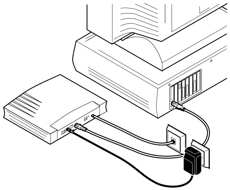
Single PC wiring
Using a hub you can connect multiple PCs to your STHome:
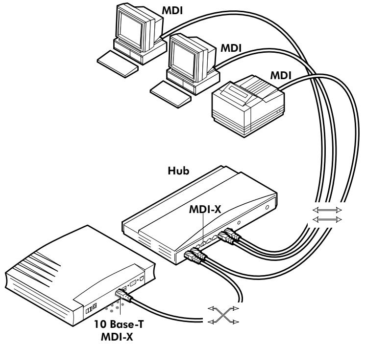
MDI vs. MDI-X hub ports and the STHome
In the above figure an MDI-X port on the hub connects to the STHome. Therefore, a crossover LAN cable is used.
Note: In case the hub's "uplink" port is used to wire the STHome you can use the included straight-through LAN cable.

Cascading Repeating Hubs
You may cascade up to four repeating hubs in your LAN (limitations of Repeating Ethernet V2.0/IEEE802.3 hubs). In case more hubs need to be cascaded, you must use switching hubs.

10Base-T Half Duplex Interfacing
Make sure the 10Base-T port(s) of your PC(s) are configured for either Auto Negotiation or Half Duplex.
Never configure the 10Base-T Ports for Full-Duplex!
1.2.3 STHome Power On/Off Behaviour
Turn on your STHome
Once all previous steps are completed, you can turn the STHome on (I) or off (O) with the power switch.
POST phases
As soon your STHome is turned on, you can check the "PWR/Alarm" LED to see how the Power On Self Test (POST) progresses.
| Phase | “PWR/Alarm” LED Indication | Description |
| 1 | Flashing red | POST pending |
| 2 | Solid amber | Start-up failed |
| Solid red | POST failed | |
| Solid green | Normal operation |
Ethernet port LED
The Ethernet port on the back panel has a LED:

| Indicator | Description | ||
| Name | Color | State | |
| Integrity | Green | Off | No connection on this port. |
| On | Ethernet link up. | ||
If the STHome and other LAN device(s) are properly connected and powered on, the particular green LED lights up.
2 Speed Touch Configuration Guide
Aim of this Quick Guide
Use this chapter to quickly configure your STHome for Internet connectivity.
In this chapter
| Topic | See |
| Check your PC configuration | 2.1 |
| Check your SP’s Service Offerings | 2.2 |
| STHome Configuration | 2.3 |
2.1 Check your PC Configuration
PC requirements
This User's Guide presents typical configurations based on PC(s) with following basic configuration:
The PC's Operating System (OS) supports the TCP/IP protocol suite
The PC is configured with a fixed "Net10" IP address (*)
A Web browser is installed.
(*) The STHome DHCP server is by default disabled.
Packet service requirements
Depending on the supported Packet Service(s) on the VC(s), the following additional requirements apply:
In case of Transparent Bridging:
The SP might provide static IP address(es) for your PC(s) or require you to enable DHCP
In case of Bridged PPPoE:
- A PPPoE session client application must be readily installed on your PC
In case of PPPOA-to-PPTP Relaying: a PPTP dial-in application(*)
The PC's OS must support Point-to-Point Protocol (PPP) and Point-to-Point Tunnelling Protocol (PPTP).
Note: All Microsoft Windows OSs support PPP and PPTP.
A PPTP Dial-Up application must be installed on your PC.
Note: All Microsoft Windows OSs have a PPTP Dial-Up application installed per default.
2.2 Check your SP's Service Offerings
Service Offering
The SP provides at least the following information:
The VPI/VCI of the Virtual Channel (VC) to use on the DSL line
The Packet Service supported on this VC
The Encapsulation Method (if different from the Connection Service's default encapsulation)
User name and Password for your User Account (if needed).
Your STHome supports multiple simultaneous VCs on the DSL line. If your SP exploits this capability, he will provide this information per VC.
Example 1:
VPI/VC1 = 0/35
Packet Service = Transparent Bridging
Encapsulation Method : Bridge default, i.e. LLC/SNAP
Example 2:
VPI/VC1 = 8/48
Packet Service = PPPoA-to-PPTP Relaying (RFC2364 PPPoA)
Encapsulation Method : pptp default, i.e. VC-MUX
User name:John Doe
Password for this User name : doejohn
Packet Service configuration
As soon as you know the Packet Service supported on a VC, you can configure your STHome, if needed.
Following combinations are possible:
| Connection Service | Packet Service |
| RFC1483 Bridging | bridge – Transparent Bridging |
| bridge – Bridged PPPoE (*) | |
| RFC2364 PPPoA | pptp – Relayed PPPoA(**) |
() A PPPoE Client application must be installed on your PC.
(^*) A PPTP Dial-Up application must be installed on your PC.
2.3 Speed Touch Configuration
In this section
| Topic | See |
| STHome Web Interface Access | 2.3.1 |
| STHome Packet Services | 2.3.2 |
| Transparent Bridging Packet Service Configuration | 2.3.3 |
| Bridged PPPoE Packet Service Configuration | 2.3.4 |
| PPPoA-to-PPTP Relaying Packet Service Configuration | 2.3.5 |
| Advanced STHome Configuration | 2.3.6 |
2.3.1 STHome Web Interface Access
STHome access
The STHome features well chosen defaults. Therefore, in most cases no additional configuration is needed for immediate Internet connectivity.
In exceptional cases additional or advanced configurations are desired, the STHome offers a user-friendly web interface.
Note: You can also configure the STHome through its Command Line Interface (CLI), accessible via a Telnet session.
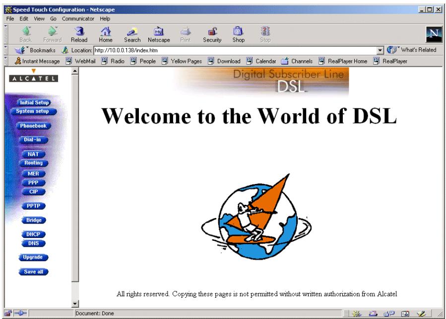
Accessing the STHome
Proceed as follows:
- Start the Web browser on your PC.
- Contact the STHome by entering one of the following:
The STHome IP address (default 10.0.0.138)
The STHome DNS hostname (default SpeedTouch.lan).
- In case the STHome is protected by a System Password and authentication window will pop up.
Enter the system password in the 'Password' field.
- As a result the 'Welcome to the World of DSL' page pops up:
Menu frame components
Each button on the left side of the STHome pages represents a STHome configuration page, yielding all configurational possibilities related to the menu subject.
Following buttons are available:
| Click this button ... | To ... |
| ALCATEL | Return to the 'Welcome to the World of DSL' page. |
| Initial Setup | Configure user defined STHome IP parameters. |
| System setup | Set a System password Perform a Browse-to-Defaults. |
| Phonebook | Overview the record of all possible, and existing ATM connections. |
| Routing | Configure the STHome IP settings. |
| PPTP | Configure the PPPoA-to-PPTP Relaying packet service. |
| Bridge | Configure the Bridging packet service. View Bridging MAC layer data. |
| DHCP | Configure the STHome DHCP server/client. |
| DNS | Configure the STHome DNS server/client. |
| Upgrade | Upgrade STHome software. |
| Save all | Save all changes made to persistent memory. |
| Help | Pop up the STHome help pages. |
Note: The following buttons have no functionality on the STHome:
Dial-in PPP and CIP
2.3.2 STHome Packet Services
What is a packet service?
Packet services are the core functions of the STHome. They provide that frames or packets get forwarded from the LAN side towards the DSL line and vice versa.
Four packet services
Transparent Bridging
Bridged PPPoE
PPPoA-to-PPTP Relaying
ATM cell switching (^*)
(*) Requires the optional ATMF-25.6 port.
Multiprotocol
All examples in this User's Guide are based on the Internet Protocol (IP) suite.
However, the STHome DSL modem is a true multiprotocol device: it can easily handle most other popular protocol suites
Examples in this User's Guide
This User's Guide presents typical configurations, but as an experienced user you are free to experiment and to find an optimal configuration.
Two access methods
Direct access
Once initial configuration is done, continuous and immediate access is available via the DSL line.
For direct access use:
Transparent Bridging
Dial-in access
In this mode access must be explicitly established, e.g. by "dialing" into a Remote Access Server (RAS).
For dial-in access use either of:
Bridged PPPoE
- PPPoA-to-PPTP Relaying.
Transparent Bridging
The STHome IEEE802.1D Transparent Bridging packet service (further referred to as Bridging) offers complete protocol transparency and has inherent configuration simplicity. Yet it provides excellent forwarding performance.
PPPoE PPPoE is one of two popular mechanisms to get in touch with the SP.
Bridged PPPoE
By installing a PPPoE client application (provided by your SP.) on your PC(s) and by using the STHome's bridge, connectivity can be established.
PPPoA The other method to get in touch with the SP over the DSL line is PPPoA.
PPPoA-to-PPTP Relaying
Similar to Bridged PPPoE this requires installation of a PPTP dial-in application (*) on your PC(s).
(*) Most popular OSs have a PPTP dial-in application installed, e.g. Microsoft Dial-Up Networking, or support PPTP Tunneling software to be installed.
The STHome packet services can be summarized as follows:
| Port | Packet Service | User/VC | IP Address | Protocol |
| 10Base-T Ethernet | Bridging | n | 1 per user | Multiprotocol |
| Bridged PPPoE | n | 1 per user | Multiprotocol (*) | |
| PPPoA/PPTP | 1 | 1 per user | Multiprotocol (*) | |
| ATMF-25.6 (optional) | ATM Cell Switching The functionality of ATM Cell switching depends on the capabilities, offered by the drivers included with the ATMF-25.6 PC-NIC. | |||
(*) The supported protocol(s) depend on the provisioning by the session client application, e.g. IP, IPX and NETBEUI for Microsoft's Dial-Up Networking application for PPPoA-to-PPTP Relaying.
2.3.3 Transparent Bridging Packet Service Configuration
Bridging configuration
Per default, following Bridging entry is preconfigured:
Br1 (Bridge on 8.35)
In case this Bridging entry does not meet your requirements, you can configure a new one as follows:
- If needed, add a Bridging phonebook entry with the correct VPI/VCI on the 'Phonebook' page.
- On the 'Bridge' page, select this phonebook entry from the 'Bridge Port' pop-down list.
- For this entry, select the correct encapsulation method.
- Click Add and Save all to finish the procedure.
Using Bridging
Make sure your STHome is turned on first.
Turn on your PC(s), start your Web browser and you are on the Internet.
Although the access method of the bridge is 'Always-on', the remote organization might ask for a user name and password.

CAUTION
Transparent Bridging and DHCP
If the SP requires you to use DHCP on your local PC(s), you must disable the STHome DHCP server.
This is to avoid conflicts between two DHCP servers.
Detailed packet service use description
For more information on the configuration and use of the Bridging packet service, see chapter 3.
2.3.4 Bridged PPPoE Packet Service Configuration
Bridged PPPoE configuration
As the Bridged PPPoE packet service implies nothing more than using the STHome Transparent Bridging packet service, no specific configuration for Bridged PPPoE is required on the STHome.
However, you may need to configure the Transparent Bridging packet service of the STHome in order to meet the requirements of your SP regarding VC(s) and encapsulation.
For more information on the configuration of the Bridging packet service, see chapter 3.
Using Bridged PPPoE
To use Bridged PPPoE, a PPPoE client must be installed on your PC. The SP will provide the PPPoE client software. Contact him for more information.
2.3.5 PPPoA-to-PPTP Relaying Packet Service Configuration
PPPoA-to-PPTP Relaying configuration
Per default, following PPTP phonebook entries are available for PPPoA/PPTP connections:
RELAY_PPP1 (PPTP on 8.48)
RELAY_PPP2 (PPTP on 8.49)
RELAY_PPP3 (PPTP on 8.50)
RELAY_PPP4 (PPTP on 8.51)
In case these PPTP phonebook entries do not meet your requirements, you can configure a new one as follows:
- If needed, add a PPTP phonebook entry with the correct VPI/VCI on the 'Phonebook' page.
- On the 'PPTP' page, select this phonebook entry from the 'Name' pop-down list.
- For this entry, select the correct encapsulation method.
- Optionally, select the type of HDLC Framing.
Note: Only in very exceptional cases the default HDLC framing (Never) must be altered.
- Click Add and Save all to finish the procedure.
Creating a PPTP connection icon
Most PPTP Tunneling applications provide a Graphical User Interface (GUI) guided procedure for the initial creation of a PPTP session icon.
The result of such creation is in most cases an icon or entry in a folder or a table called 'RAS', 'Dial-Up Networking', 'PPTP', 'Call sessions', 'Remote Access', etc.
PPTP connection parameters
During the initial configuration of your PPTP connection icon, you must provide the following parameters:
A name for the PPTP connection icon
The VPN server's IP address or DNS hostname, i.e. the STHome's IP address or DNS hostname.
Optionally, you can complete this entry with
The VC's PPTP phonebook name — configured on your STHome — to be used for this connection.
Note: Only in case multiple PPTP phonebook entries are directed towards different destinations, you must add the appropriate phonebook name to the dial-string. This allows the STHome to open the session to the correct specific destination. In case all PPTP phonebook entries are directed towards the same destination, it is better not to add a phonebook name to the dial-string.
Detailed packet service use description
For more information on the configuration and use of the PPPoA-to-PPTP Relaying packet service, see chapter 3.
2.3.6 Advanced STHome Configuration
Overview Use the following parts to explore STHome's capabilities:
| Alcatel Speed Touch™ Configuration | |
| Bridging and Bridged PPPoE | 3 |
| PPPoA-to-PPTP Relaying | 4 |
| Alcatel Speed Touch™ Networking | |
| ATM | 5 |
| IP, DHCP and DNS | 6 |
| Alcatel Speed Touch™ Maintenance | |
| Alcatel Speed Touch™ Software | 7 |
| Alcatel Speed Touch™ Password | 8 |
| Alcatel Speed Touch™ To-Defaults | 9 |
| Alcatel Speed Touch™ Appendices | |
Learning more
The STHome is an advanced product. Describing everything in detail goes beyond the perspective of this User's Guide.
However, in case you want to explore STHome's possibilities and interfaces in deep, you can always consult other Alcatel Speed Touch™ DSL product's User's Guides available from Alcatel's Support website at:
http://www.alcatel.com
http://www.alcateldsl.com
Alcatel Speed Touch™ Home
Configuration
3 Configuration - Bridging and Bridged PPPoE
Transparent Bridging
Transparent Bridging is the packet service of your choice as it:
Is platform and OS independent
Is true multiprotocol
Has no performance limitations in the Alcatel implementation
Has almost no constraints on the number of attached users.
Bridged PPPoE
The STHome transparent bridge can be used in combination with a PPP over Ethernet (PPPoe) client installed on your PC.
The resulting Bridged PPPoE packet service provides similar dial-in experience as found on point-to-point connections.
The 'Bridge' page
Click Bridge in the left pane of the STHome pages to pop up the 'Bridging' page:
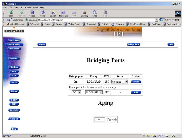
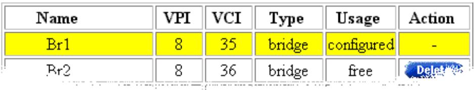
Tables The 'Bridging Ports' table indicates all currently configured Bridging entries and allows to add or delete entries.
The 'Aging' box indicates the aging timer of the bridge internal database. The allowed range is from 10 seconds to 12 days.
Transparent Bridging relies completely on its filtering database for its frame forwarding through the bridge. Click Bridge data on the 'Bridge' page to overview all current MAC entries.
Adding entries
- Browse to the 'Bridge' page.
- Select the phonebook entry from the 'Bridge port' pop-down list.
Note: In case the presented phonebook entries do not suite your desired configuration, you must firstly create a correct phonebook entry. See section 5.2 for more information.
- Select the encapsulation method for the Bridging port from the 'Encap' pop-down list (per default set to LLC/SNAP).
- Click Add and Save all to finish the procedure.
Deleting entries
On the 'Bridge' page, click Delete next to the Bridging entry you want to delete. As a result your selection is deleted.
Click Save all
4 Configuration - PPPoA-to-PPTP Relaying
Introduction
PPPoA-to-PPTP Relaying(*) is the packet service of your choice as it:
Provides standard Dial-in PPP behavior
Supports security via identification, authentication and encryption
Has multiprotocol support depending on the PPTP implementation, e.g. for MS Windows: TCP/IP, IPX/SPX and NETBEUI
Offers complete TCP/IP protocol transparency; no NAPT is required
Supports concurrent access to multiple remote destinations (depending on provisioning).
(*) PPPoA-to-PPTP Relaying is also referred to as Delayed PPP over ATM (PPPoA) or PPPoA/PPTP.
Topics
| Topic | See |
| MS Windows 98 Dial-Up Networking | 4.1 |
| PPPoA/PPTP Configuration | 4.2 |
4.1 MS Windows 98 Dial-Up Networking
In this section
The following overview summarizes the necessary steps to setup a Microsoft Windows 98 PC for the use of PPPoA-to-PPTP Relaying:
| Step | Action | See |
| 1 | Configure a Private IP address on your PC | |
| 2 | Create a new Dial-Up Networking icon | 4.1.1 |
| 5 | Open a Dial-Up Session | 4.1.2 |
| 6 | Surf the Internet. | |
| 7 | Close a Dial-Up Session in Use | 4.1.2 |
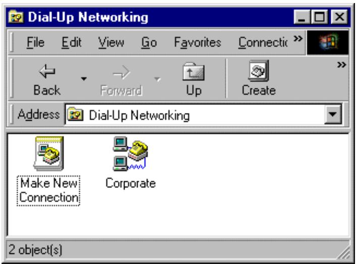
4.1.1 Create a New Dial-Up Networking Icon
Procedure Proceed as follows:
| Step | Action and Description |
| 1 | Double-click the 'My Computer' icon on your desktop. My Computer |
| 2 | Double-click the 'Dial-Up Networking' icon. Dial-Up Networking |
| 3 | Double-click the 'Make New Connection' icon to activate the 'Make New Connection' wizard. Make New Connection |
| 4 | If you use the Dial-Up Networking application for the first time, the 'Welcome to Dial-Up Networking' window appears. In that case, click Next > The 'Make New Connection' window pops up: Make New Connection Type a name for the computer you are dialing: Corporate Select a device: Microsoft VPN Adapter Configure... |
| 5 | In the first input field of the 'Make New Connection' window, type a name, e.g. an alias for the organization you are connecting to. Note: This name will appear below the Dial-Up icon at the end of this procedure. |
| 6 | In the 'Select a device' listbox of the 'Make New Connection' window you must select the 'Microsoft VPN Adapter' for PPTP tunneling. |
| 7 | Click Next > to pop up the VPN server window: Make New Connection Type the name or address of the VPN server: Host name or IP Address: 100013E < Back Next > Cancel |
| 8 | Enter the DNS hostname or IP address of the Virtual Private Net-work (VPN) server. Note: "VPN server" is another word for PPTP server, which is in this case your STHome. The default IP address for the STHome is 10.0.0.138. Its default hostname is "SpeedTouch". Optionally, you can add the phonebook name to specify which VC is to be used for the connection. |
| 9 | A window pops up confirming that you have successfully installed a new Dial-Up connection. Click Finish to finish the procedure. |
Result A new icon with the name of the connection you have just created will be added to your 'Dial-Up Networking' folder:
Creating multiple Dial-Up icons for multiple destinations
Per destination you can create a unique icon. To do so, repeat the steps starting with step 3 of the previous procedure.
4.1.2 Opening and Closing a Dial-Up Session
Opening a session Proceed as follows:
| Step | Action and Description |
| 1 | Double-click the appropriate Dial-Up icon in the 'Dial-Up Networking' folder or double-click its shortcut on your desktop. Corporate The 'Connect To' window pops up: |
| Connect To Corporate User name: John Doe Password: xxxx Save password VPN server: 10.0.0.138 Connect Cancel | |
| 2 | Fill in your user name and password, according your user account at the SP. Note: If you want the current Dial-Up connection to remember your credentials for future use, check the 'Save Password' box (✓). Make sure though, that you have logged in when you boot your PC. |
| 3 | Click Connect The 'Connecting To Corporate' window appears shortly before being minimized in the system tray: 2:31 PM |
| 4 | Start your application now, e.g. a Web browser. |
While you are connected
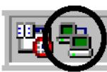
Once the Dial-Up connection is established, you can find the MSDUN icon showing two PCs connected to each other in the system tray:
2:31 PM
The MSDUN icon symbolizes activity on the PPPoA/PPTP connection by flashing PC(s):
A flashing "Front" PC symbolizes upstream (T_X) link activity (from your local PC towards the STHome)
A flashing "Behind" PC symbolizes downstream (R_X) link activity (from the STHome towards your PC).
Closing a session
Proceed as follows:
| Step | Action and Description |
| 1 | If the Dial-Up connection is minimized, click the MSDUN icon in the system tray: 2:31 PM The 'Connected To' window pops up. |
| 2 | Click Disconnect to close the Dial-Up session. |
Result The PPTP tunnel to the STHome will no longer exist. The PPPoA/PPTP entry on the STHome is made available again for other users.
4.2 PPPoA/PPTP Configuration
The 'PPTP' page
Click PPTP in the left pane of the STHome pages to pop up the 'PPTP' page:
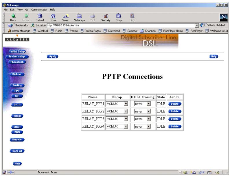
Tables The 'PPTP Connections' table indicates all currently configured PPPoA-PPTP Relaying entries and allows to add or delete entries.
Adding entries
- Browse to the 'PPTP' page.
- Select the phonebook entry from the 'Name' pop-down list.
- Select the encapsulation method for the PPPoA/PPTP entry from the 'Encap' pop-down list (per default set to VC-MUX).
- Select the HDLC framing from the 'HDLC' pop-down list (per default set to "never").
- Click Add and Save all to finish the procedure.
Deleting entries
On the 'PPTP' page, click Delete next to the PPPoA/PPTP entry you want to delete. Click Save all to finish the procedure.
Alcatel
Speed Touch™Home
Networking
5 Networking - ATM
Introduction
All data arriving at and departing from your STHome via the DSL line is carried in Asynchronous Transfer Mode (ATM) cells.
In this way, ATM is the fundamental communication "language" for the STHome towards the remote devices.
The dual port STHome model, equipped with the additional ATMF-25.6 port, is even capable to extend ATM connectivity up to your local PC or local network (via ATM switches).
In this chapter
| Topic | See |
| The ATM Packet Switching Technology | 5.1 |
| The STHome Phonebook | 5.2 |
| AutoPVC | 5.3 |
5.1 The ATM Packet Switching Technology
ATM Switching
ATM is a connection-oriented packet switching technology using fixed-size packets, called cells.
These cells consist of a header and a payload and are switched through a public or private ATM network depending on the contents of the header.
End-to-end connections are formed by cross-connecting individual ATM segments in ATM switches.
Each ATM cell carries two labels called Virtual Path Identifier (VPI) and Virtual Channel Identifier (VCI) as part of its header.
An ATM channel, commonly referred to as Virtual Channel, is fully identified by these two labels. Therefore, multiple ATM channels can reside on your DSL line.
All STHome ATM connections are static, i.e. of type Permanent Virtual Channel (PVC).
End-to-end ATM connectivity
The following figure provides an overview of the end-to-end architecture of the ATM connectivity; from your STHome to remote access devices.
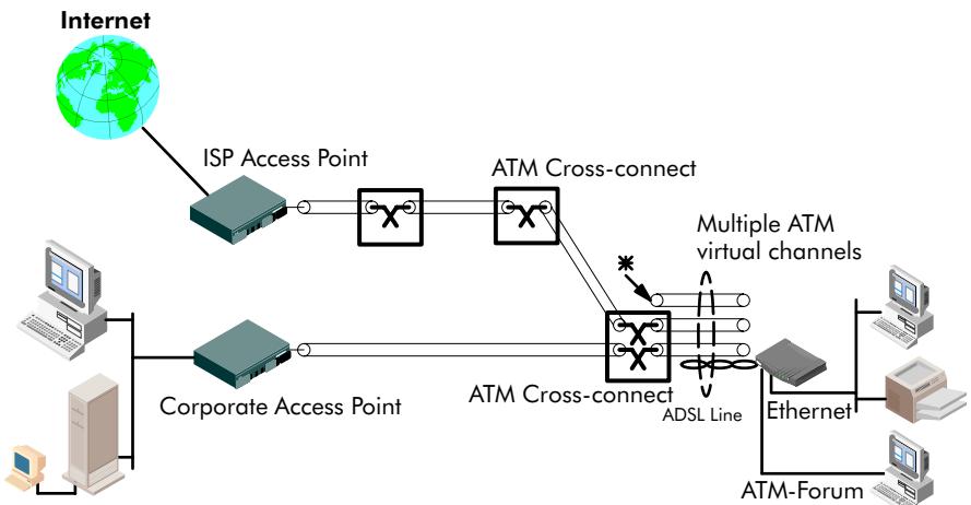
* This channel is not cross-connected
Hence no end-to-end connectivity!
Symbolizes a cross connection.
ATMF-25 port
This port, optional available on the single Ethernet port STHome, does not terminate ATM connections, it just switches ATM cells between the DSL and ATMF-25.6 port.
It is the ATMF-25.6 PC-NIC of the PC that actually initiates, or terminates ATM VCs.
It is important to check in advance which protocols are supported by the ATMF-25.6 PC-NIC driver. At least RFC1483 and RFC2364 should be fully implemented.
Ethernet port
This port terminates a number of ATM connections and extracts frames from arriving cells and encapsulates frames in departing cells.
Only frames recognized/supported by the STHome on a particular ATM connection are extracted, or encapsulated.
Currently the supported encapsulations are:
For Transparently Bridged connections:
RFC 1483, Ethernet V2.0/IEEE 802.3 bridged PDUs for both the LLC/SNAP method and VC-MUX method
For Bridged PPPoE connections:
RFC 1483, Ethernet V2.0/IEEE 802.3 bridged PDUs for both the LLC/SNAP method and VC-MUX method
For PPPoA-to-PPTP Relaying connections:
RFC 2364, PPP PDUs for both the LLC/NLPID method and VC-MUX method.
5.2 The Speed Touch Phonebook
Introduction
The STHome phonebook is like any ordinary phonebook:
"A repository for names and numbers".
However, in contrast to a standard phonebook, it contains additional connectivity information.
Basic to the STHome operation are ATM VCs. The STHome phonebook is the management tool for all possible ATM VC connections.
This section describes how to use the STHome phonebook, and consequently how to manage this VC pool.
The 'Phonebook' page
Click Phonebook in the left pane of the STHome pages to pop up the 'Phonebook' page:
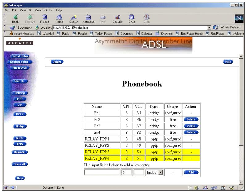
Tables
The 'Phonebook' table indicates all currently configured phonebook entries and allows to add or delete entries.
The 'AutoPVC' table lists all PVCs communicated via AutoPVC. If AutoPVC is not supported at the remote side, i.e. the Digital Subscriber Line Access Multiplexer (DSLAM), the 'AutoPVC' table stays empty.
Restrictions for adding phonebook entries
Although you are free to give any name to a phonebook entry, a few restrictions apply:
You may not provide an entry with a name which already is supplied in the 'Phonebook' table.
Phonebook entries, which are intended to be used for the PPPoA-to-PPTP Relaying packet service may not start with a capital 'P', or a capital 'T'.
Each entry in the STHome phonebook must have a unique VC, i.e. a unique VPI/VCI combination. Adding a phonebook entry with a VPI/VCI, which is already used in the 'Phonebook' table, will result in an error message.
Adding phonebook entries
Proceed as follows:
- Browse to the 'Phonebook' page.
- Enter a name of your choice to identify the new phonebook entry in the 'Name' field.
- Enter the VC's VPI and VCI values in the 'VPI' and 'VPI' fields. Note: In most cases these values are provided by your SP.
- Select the Packet Service of your choice, or choose any from the 'Type' pop-down list.
- Click Add and Save all to finish the procedure.
Deleting phonebook entries
On the 'Phonebook' page, click Delete next to the phonebook entry you want to delete. As a result your selection is deleted. Click Save all
5.3 AutoPVC
AutoPVC
The default VCs, can be remotely modified via the AutoPVC feature of the STHome. AutoPVC operates only in conjunction with the Alcatel Digital Subscriber Line Access Multiplexer (DSLAM) – often referred to as ATM Subscriber Access Multiplexer (ASAM) – and offers the following functionality:
User VCs that are to be terminated on the Ethernet port, can be notified by the STHome (AutoPVC list and yellow bar)
User VCs that need to be cross-connected between the DSL port and the ATMF-25.6 port, can be remotely established.
Example
Suppose the SP configures one of the STHome's default terminated VCs, e.g. 8/35, on the DSLAM.
VPI/VCI 8/35 will end up in the 'AutoPVC' list:
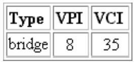
As this VC matches with the Bridging entry Br1, this phonebook entry will be highlighted in the 'Phonebook' table:
Phonebook
In this way the user can distinguish the activated VC from dummy phonebook entries.
6 Networking Services - IP, DHCP and DNS
Introduction
For Internet access, and home networking, IP^(*) plays a crucial role. Due to the flexibility and the multitude of IP features, numerous configurations are possible.
(*) Although not the same, IP is often referred to as Transmission Control Protocol (TCP)/IP.
In this chapter
| Topic | See |
| Packet Services and IP | 6.1 |
| STHome Addresses | 6.2 |
| STHome DHCP | 6.3 |
| STHome DNS | 6.4 |
6.1 Packet Services and IP
Introduction
In this section the interaction between IP addresses and packet services is described.
Apart from Bridging, all packet services require the IP suite, and even the Bridging packet service will in most cases be used in combination with IP addressing.
In this section
| Topic | See |
| Transparent Bridging | 6.1.1 |
| PPPoA-to-PPTP Relaying | 6.1.2 |
6.1.1 Transparent Bridging
IP vs. Bridging
Basically, Bridging does not require any IP address at all: neither in your PC(s), nor in your STHome.
However, in case of Internet access, private IP networking or in case the Bridging packet service is used for Bridged PPPoE, your PC(s) must be configured for TCP/IP.
Typical Bridging setup
In most cases, your SP will require you to use DHCP for your PC. In this case the DHCP server is at the remote side of the DSL connection. Therefore, your STHome's DHCP server must be disabled.
Using TCP/IP and Bridging
Your SP may:
Provide you with an IP address
Require you to use DHCP.
Local IP communication
Alternatively, a second but Private IP address can be manually configured for local IP communication. It depends on your OS whether it supports this combination.
e.g. Microsoft supports Logical Multihoming via Registry keys.

Bridging & DHCP Service
The STHome DHCP server is by default disabled.
In case you use your STHome in Bridging mode and your ISP requires you to enable DHCP in your PC(s), the DHCP server inside the STHome must be disabled to avoid conflicts between two DHCP servers being active at the same time.
Setting the DHCP modes of your STHome is described in section 6.3.
6.1.2 PPPoA-to-PPTP Relaying
IP vs. PPPoA/PPTP
Prior to using PPTP, local IP addresses must be configured. The use of these IP addresses is limited to the local network.
Private IP addresses
You are free to choose any IP address as long as it is compatible with your local network and is unique in that same network.
As the STHome has a preconfigured "Net10" address (10.0.0.138), you should configure IP addresses like 10.0.0.1, 10.0.0.2, ... on your PCs.
Note: IP addresses can be configured automatically via STHome's DHCP server. See section 6.3 for more information.
Public IP addresses
A second set of (Public) IP addresses having end-to-end scope will automatically be negotiated via the PPP protocol inside your PC(s).
Simultaneous use of public & private IP
Both Public and Private IP addresses are active simultaneously because of tunneling. In fact two "nested" IP layers exist: the Public IP layer which is carried within the Private IP layer on the local LAN.
PPP IP address negotiation
By default the PPTP tunnel application automatically negotiates the Public IP address.
In case your SP instructs you to use a static IP address for Relayed PPPoA, most dial-in applications allow a static IP address to be supplied.
6.2 Speed Touch Addresses
Introduction
Like any other member of a LAN, the STHome must be locally identified by an IP address to be able to communicate with other local LAN devices.
This section deals with the IP address configuration of the STHome for local communication only.
Assigning IP addresses to the STHome
IP addresses can be assigned to the STHome in several ways. Summarized, following IP address types exist:
The default IP address: 10.0.0.138
IP addresses assigned via the 'Initial Setup' page
IP addresses assigned via a 'Ping-of-Life™
IP addresses assigned to the STHome via DHCP.
STHome and multiple IP addresses
As the STHome IP layer supports logical multi-homing (one interface supporting multiple IP addresses), both statically and dynamically configured IP address(es) can be active at the same time.
'IP address' table
On the STHome 'Routing' page the 'IP address' table summarizes all IP addresses configured on any of the STHome interfaces.
Setting an IP address via the 'Initial Setup' page
Proceed as follows:
- Click Initial Setup in the left pane of the STHome pages to pop up the 'Initial Setup' page:
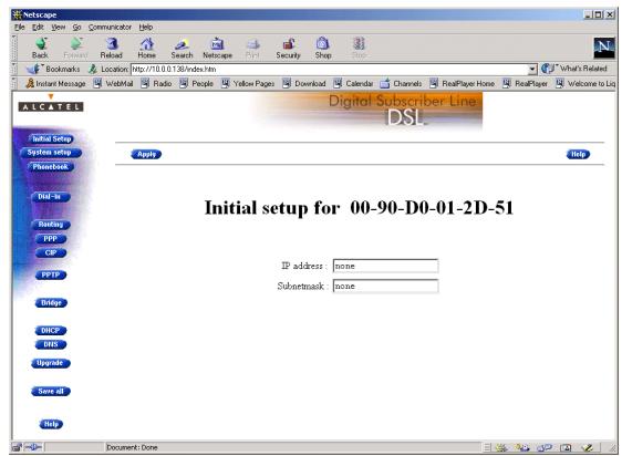
- Enter an IP address in the 'IP Address' field.
- Enter a netmask for applying subnetting in your network in the 'Subnetmask' field.
- Click Apply . As a result the new IP settings are applied:
RESULT : the IP settings have been applied. Change the IP settings on your own machine (if needed) and point your browser at the new address (http://10.0.0.151/) to verify connectivity with the new configuration. Use 'Save all' to make it permanent.
- To verify connectivity, point your Web browser to the new IP address. Make sure though that your PC shares the same subnet.
- Click Save all to store the applied IP settings to permanent storage.
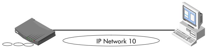
Sample configuration: single PC
In the below figure, a simple configuration is given: One PC attached to the STHome:
IP address : 10.0.0.138
(Sub)netmask:255.255.0.0
Default Gateway : none
IP address : 10.0.0.1
(Sub)netmask:255.255.0.0
Default Gateway : none
6.3 Speed Touch DHCP
DHCP Depending on the size and complexity of your network, a few DHCP configurations can be envisaged:
| LAN Type | DHCP Mode | Argumentation |
| Simple | No | All few members of the small LAN have static IP addresses, including the STHome. |
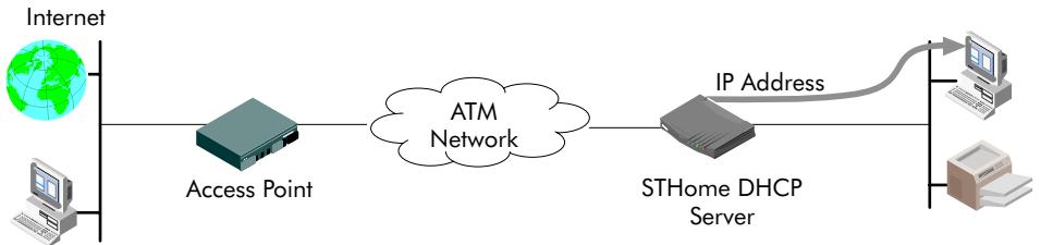
| Medium sized | Server | For small home LANs it might be worthwhile to configure all of your LAN devices as DHCP clients, and the STHome as the DHCP server. In this configuration each time a computer starts, it will obtain its IP configuration from the STHome. |
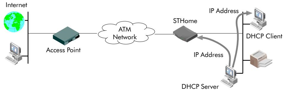
| Advanced | Client | For advanced networks, the role of DHCP server might be performed by an IP node other than the STHome on the local LAN. |
Default STHome DHCP Per default the STHome DHCP server is disabled.
The 'DHCP' page
Click DHCP in the left pane of the STHome pages to pop up the 'DHCP' page:
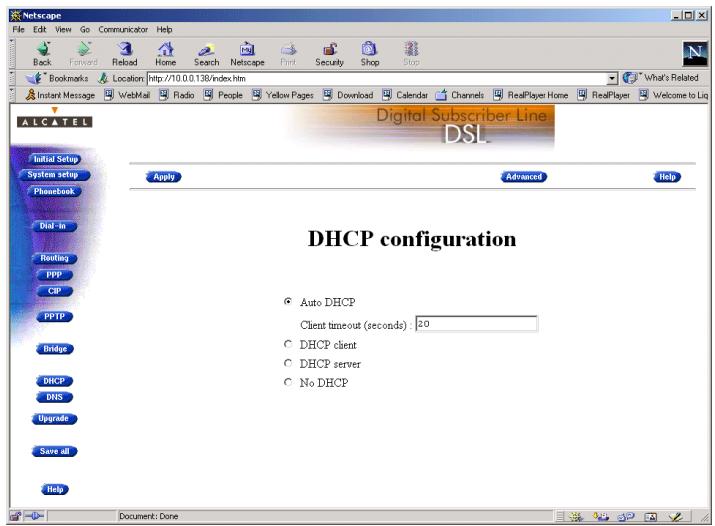
'DHCP Server Start-up Mode' radiobuttons
The 'DHCP Server Start-up Mode' radiobutions allow to configure the STHome DHCP server mode.
Configuring the STHome for a LAN without DHCP
To setup the STHome without DHCP, tick No DHCP.
In this configuration, it is assumed that all members, the STHome included, have static IP addresses.
See subsection 6.2 for static IP addressing of the STHome.
Note: This configuration might be required in case you use the Transparent Bridging packet service.
Configuring the STHome as DHCP server
To setup the STHome as DHCP server, tick DHCP server.
Via the 'DHCP Server Configuration' tables, you can configure the STHome DHCP server settings.
Note: This setting might cause side effects with Bridging. See section 6.1.1 for more information.
Configuring the STHome as DHCP client
To setup the STHome as DHCP client, tick DHCP client on the 'DHCP' page.
Configuring the STHome for Auto DHCP
One of the STHome features is that it can automatically revert from DHCP client to DHCP server.
At boot time the STHome probes the LAN for a specified time limit ('Client timeout') to check whether another DHCP server is available on the network. If so, it will act as a DHCP client. If no response is received within the specified time, the STHome becomes a DHCP server.
To allow the STHome to act as Auto DHCP client/server, tick

Auto DHCP
Additionally, you can configure the 'Client timeout' in seconds:
Client timeout (seconds): [20
Via the 'DHCP server configuration' tables, you can configure the STHome DHCP server settings.
DHCP server configuration
Click Advanced on the 'DHCP' page to pop up the 'DHCP server configuration' page.
You can configure following DHCP server parameters:
| Field | This configures ... | Default |
| Addresses through ... | The range of addresses the DHCP server can choose an IP address from for lease. | "Net10" |
| Subnet Mask | The subnetting applied to the local network, scoped by the DHCP server. | no subnetting |
| Lease Time | The time (Lease Time) IP addresses can be assigned to a device by DHCP. | 7200 seconds |
| Default Gateway | The IP address of the default gateway. | 'auto' (*) |
| DNS Server | The IP address of the DNS server. | 'auto'(**) |
() Setting 'auto' in the 'Def. Gateway' field means, that there will be referred to the 'Routing' page.
(*) Setting 'auto' in the 'DNS server' field means, that there will be referred to the 'DNS' page.
6.4 Speed Touch DNS
Introduction
IP addresses are fundamental to the operation of the Internet. IP addresses, being 32-bit numbers, are ideally suited for computers but are far from usable to humans.
Therefore, the Domain Name System (DNS) was designed: a distributed database, held by a hierarchical system of servers, that is used by TCP/IP applications to map between hostnames and IP addresses.
This chapter describes STHome's DNS abilities.
The 'DNS' page
Click DNS in the left pane of the STHome pages to pop up the 'DNS' page:
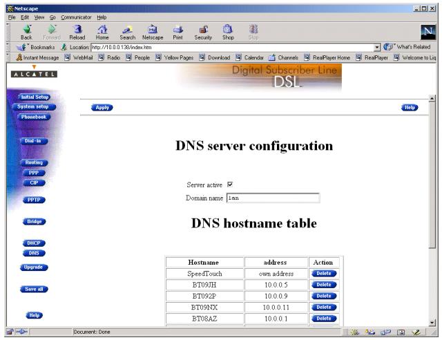
Configuring the DNS server
Check the 'Server active' checkbox to enable the STHome DNS server (per default enabled).
In the 'Domain name' field you can enter the domain name of your LAN (default domain name is 'lan'). You may use a DNS subdomain name, e.g. dsl.office.lan. Click Apply and Save all to finish.
Alcatel
Speed Touch™Home
Maintenance
7 Maintenance - Speed Touch Software
Software Upgrade
The STHome supports two software upgrade possibilities:
You can upload new STHome software yourself from a PC on your local LAN
A new version of the software can be downloaded via the DSL line to your STHome.
Both features are simultaneously supported. However the final result depends on the SP's policy.
The 'Upgrade' page
Click Upgrade in the left pane of the STHome pages to pop up the 'Upgrade' page:
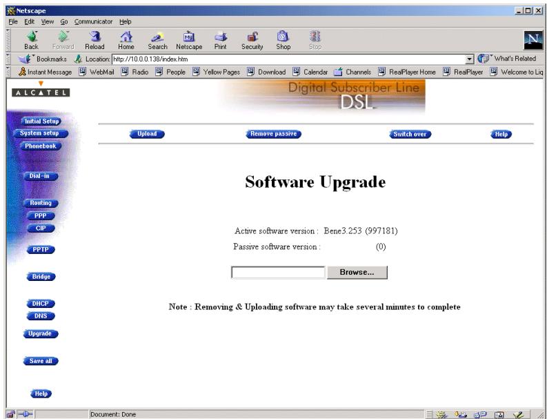
'Upgrade' page components
The following fields are shown:
'Active software version'
Indicates the software version the STHome is currently using.
'Passive software version'
Indicates the software version resident in the STHome, but not used. This could be a newer version which is yet to be switched to active, but also a dormant older version.
Software path field
Allows you to specify the path to the STHome upgrade software package to be uploaded.
Clicking Browse... allows you to browse to the location of the upgrade software.
Upgrade Preconditions
A valid STHome software package must reside either on a local drive, on a floppy disk or a CD-ROM.
For new software upgrade packages, please contact your SP or check the Alcatel web sites at:
http://www.alcatel.com
http://www.alcateldsl.com
Software upgrade via your LAN
Proceed as follows:
-
Browse to the 'Upgrade' page.
-
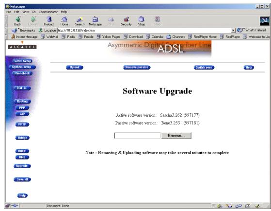
In the 'Active software version' field the software package that is running is labeled.
Check whether the 'Passive software version' field is empty. If not, click Remove passive
- Click Browse... next to the 'Software path' input field to locate the upgrade software package
Note: If the path is known you can immediately enter it in the Software path' input field and skip step in this procedure.
- The 'File Upload' window pops up. This window allows you to browse to the location of the upgrade software package on either your local drive, floppy, or CD-ROM.
- Click on the appropriate upgrade software package name to select it and click Open
As a result, the upgrade software location will be inserted in the 'Software path' input field.
- Click Upload to start the upload. As a result the upgrade software package name will appear in the 'Passive software version' field.
- Click Switch over to start the switching of the two versions.
After switching the versions, the STHome reboots and will come online with the upgrade version. On the 'Upgrade' page you will notice that the active and passive software names are switched:
Software upgrade via the SP
The STHome supports a second software upgrade possibility: a new version of the software can be downloaded from the DSL network to your STHome via dedicated control VCs.
This feature is controlled by the SP. Software download will happen almost unnoticed, while you are connected to the DSL line. The removal of a possible dormant software version, the download itself, and the switching of both versions is performed automatically.
Note: DSL service can be interrupted for a short period due to a reboot of the STHome.
8 Maintenance - Speed Touch Password
In this chapter
Your STHome is a highly advanced product, operating according the many configurations set via the STHome Web interface or via the CLI.
In this way STHome operation is vulnerable to misconfiguration by other users.
Therefore, the STHome can be secured from such users by a system password to restrict access to the Web interface, or the CLI. This chapter describes how to set such a system password.
Note
Never use an obvious system password to protect the STHome as your name, birth date, or phone number.
Moreover, you are advised to change the system password regularly.

Forgetting the System Password
In case you forgot the system password you are no longer able to access the web interface or the CLI and you will be no longer able to (re)configure the STHome settings.
Therefore, write your system password down and keep it on a save place.
Otherwise, a Switch-to-Defaults must be performed restoring all original settings of the STHome.
Setting a system password
Proceed as follows:
- Click System setup on the STHome pages to pop up the 'System setup' page:
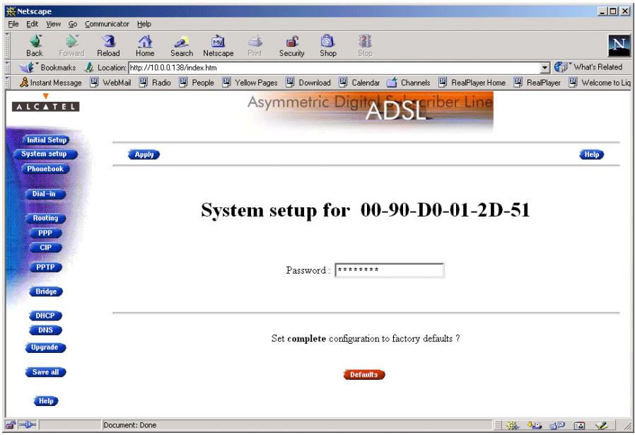
- In the 'Password' field, fill in a password.
Note: Asterisks will appear instead of the password. The number of asterisks is at random.
- Click Apply
- To make your password permanent, click Save all
5.伪造 your password, using the system password, you just configured.
Result
Every time you want to access the STHome pages or (Telnet) CLI you must authenticate yourself, using the system password.
Clearing a system password
To clear the STHome system password you must clear the 'Password' field, i.e. delete all asterisks. Click Apply and Save all to store your changes.
No authentication is required anymore to access the STHome pages or the (Telnet) CLI.
9 Maintenance - Speed Touch To-Defaults
Introduction
Non accessibility to your STHome may occur if wrongly configured, simply by forgetting its IP address, or forgetting the system password.
Due to the flexible nature of the STHome, you may end up in a situation where restoring all of the original defaults is the only solution.
The STHome has tools to cope with these situations.
In this chapter
| Topic | See |
| Ping-of-Life™ | 9.1 |
| STHome Reset | 9.2 |
9.1 Ping-of-Life
Introduction
The STHome offers a unique method to supply an IP address to the STHome's Ethernet port.
This method, the Ping-of-Life™, allows to provide the STHome with an IP address without affecting other configurational settings.

IP Addresses and Subnet Masks
Make sure that the intended STHome IP address and your PC share the same IP (sub)network.
If not, the ping will be submitted with the MAC address of the default router instead of the special MAC group address.
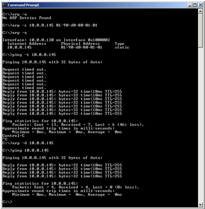
The Ping-of-LifeTM procedure
Proceed as follows:
- Turn off the STHome.
- Open a command-line (DOS) window (Windows OS), or a terminal window (UNIX, Linux) on a PC.
- At the command prompt execute: arp -a
This allows you to overview the current entries in the ARP cache.
4. Add a static entry to the ARP cache, according to following syntax:
arp -s
5. To verify whether this step was successful execute arp -a a second time.
In the entries list, your arp -s command entry should be added.
6. Initiate a continuous pinging, by executing following command:
ping -t
7. Turn on the STHome.
- After the STHome finished its POST, it will configure the IP address
you are pinging. - You must clear the entry in the ARP cache by issuing the following command:
arp -d
- Verify connectivity by pinging the STHome a second time:
ping
The STHome should reply.
- Browse to the STHome pages and click Save all to make the new IP address permanent.
Example DOS box
In the following figure all the steps are shown as an example of setting STHome's IP address to 10.0.0.145 from a PC with an MS Windows OS:
9.2 Speed Touch Reset
Overview of the To-Defaults methods
To restore STHome's original settings, three methods are provided:
Two local software methods:
Browse-to-Defaults
Which sets all parameters to original defaults, but keeps the system password and IP address.
- Ping-to-Defaults™
Which sets all parameters to original defaults, including the system password and IP address.
One hardware method: Switch-to-Defaults.

Restoring Original Settings
Be careful when using the Browse-to-Defaults, Ping-to-Defaults™, or the Switch-to-Defaults procedures as these destroy changes you previously made to the STHome internal settings.
A reset to defaults via a Ping-to-Defaults™, or via a Switch-to-Defaults, also implies the STHome's IP address is reset to 10.0.0.138.
In this section
| Topic | See |
| Browse-to-Defaults | 9.2.1 |
| Ping-to-Defaults™ | 9.2.2 |
| Switch-to-Defaults | 9.2.3 |
9.2.1 Browse-to-Defaults
Procedure
Proceed as follows:
- Click System setup on the STHome pages to pop up the 'System setup' page:
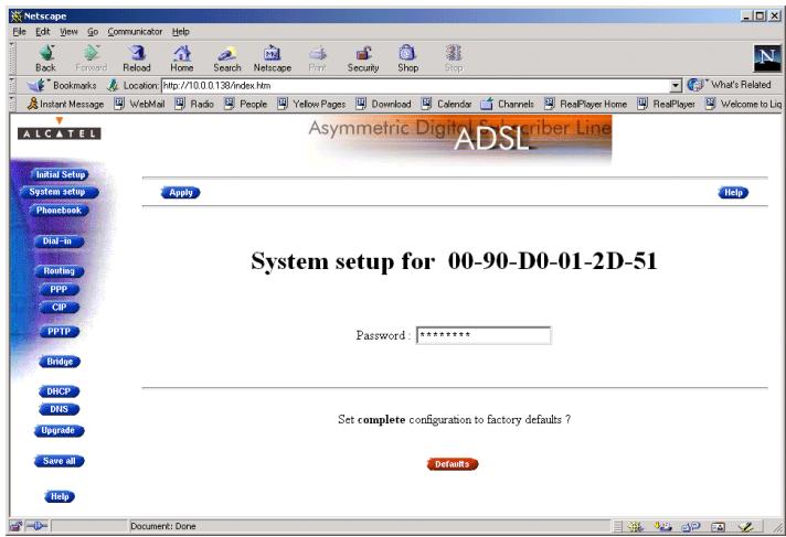
- Click Defaults if you are sure to reset the STHome to its original defaults.
- The STHome will ask to confirm the reset:
Confirm reset to defaults of complete configuration OK Cancel
- Click OK if you are sure. Otherwise click Cancel.
- Click Save all to make the Browse-to-Defaults permanent.
- Press the reload button of your Web browser.
Browse-to-Defaults result
After reset, all original configurations of the STHome are restored, except the STHome Ethernet IP address(es).
9.2.2 Ping-to-Defaults
Introduction
A second software method to reset all settings to the original defaults is the Ping-to-Defaults™.
The technique is identical to that used for the Ping-of-Life™, except that another MAC address is used, i.e. 01-90-D0-80-01-FF.
Procedure
Proceed as follows:
- Turn off the STHome.
- Open a command-line (DOS) window (Windows OS), or a terminal window (UNIX, Linux) on a PC.
- Add a static entry to the ARP cache, according to following syntax:
arp -s
- To verify whether this step was successful execute arp -a
- Initiate a continuous pinging, by executing following command:
ping -t
- Turn on the STHome.
- After the STHome finished its POST, it will perform a reset to default settings.
- You must clear the entry in the ARP cache by issuing the following command:
arp -d
- If needed, reconfigure the STHome IP address, e.g. via a Ping-of-Life™.
Note
The used
9.2.3 Switch-to-Defaults
Introduction At the back of the STHome there is a small push button labeled "Defaults".
Via this button a hardware reset of the STHome, the Switch-to-Defaults, is possible.
Procedure Proceed as follows:
- Make sure your STHome is turned on.
- Use a pencil to press the push button at the back of the STHome.
- Release the button. Via the flashing front panel LEDs, you will notice that the STHome will reboot.
Wait to allow the POST to end. The STHome will come online with manufacturing defaults.
- After a reset to original defaults a reconfiguration of STHome's IP address might be necessary. This because the reset to defaults also resets your STHome's IP address to its default value 10.0.0.138.
Alcatel
Speed Touch™Home
Appendices
Abbreviations
ADSL Asymmetric Digital Subscriber Line
ASAM ATM Subscriber Access Multiplexer
ATM Asynchronous Transfer Mode
ATMF-25.6 ATM Forum - 25.6 Mbps
CLI Command Line Interface
DNS Domain Name System
DSLAM Digital Subscriber Line Access Multiplexer
DTE Data Terminal Equipment
GUI Graphical User Interface
IP Internet Protocol
ISDN Integrated Services Digital Network
ISP Internet Service Provider
ITU International Telecommunication Union
LAN Local Area Network
NIC Network Interface Card
OS Operating System
PC Personal Computer
POST Power On Self Test
POTS Plain Old Telephone Service
PPP Point-to-Point Protocol
PPP0A PPP over ATM
PPPoe PPP over Ethernet
PPTP Point-to-Point Tunnelling Protocol
PVC Permanent Virtual Channel
RAS Remote Access Server
REN Ringer Equivalence Number
ROW Rest Of the World
SELV Safety Electronic Low Voltage
SP Service Provider
TCP Transmission Control Protocol
TNV Telecommunication Network Voltage
| URL | Uniform Resource Locator |
| VC | Virtual Channel |
| VCI | Virtual Channel Identifier |
| VP | Virtual Path |
| VPI | Virtual Path Identifier |
| VPN | Virtual Private Network |
AppendixA
Speed Touch Troubleshooting
Introduction
This appendix provides information on how to identify and correct some common problems you may encounter when using and configuring the STHome.
If the following troubleshooting tips have not resolved the problem, contact the company from which you purchased the STHome for assistance.
Configuration problems
In case you encounter DSL connectivity problems due to misconfiguration, you might consider a reset to original defaults. However, be aware that a reset to original defaults destroys all configurational changes you made to the STHome internal settings.
Trouble solving table
The following table provides possible solutions to some problems:
| Problem | Solution |
| STHome does not work. (none off the LEDs lights up) | Make sure the STHome is plugged into an electrical outlet. |
| Make sure the power switch on the STHome modem is turned on. | |
| No ATMF-25.6 connectivity. | Make sure the (correct) cable is securely connected to the ATMF-25.6 port. |
| No Ethernet connectivity. LAN LED does not light up. Ethernet port(s) link integrity LED does not light up. | Make sure the cable(s) are securely connected to the 10Base-T port(s). |
| Make sure you are using the correct cable type for your Ethernet equipment. | |
| Telnet session from a Windows PC is not possible. | The STHome system password is longer than 8 characters. Change the STHome system password. |
| Poor STHome performance. | Make sure the STHome is installed as instructed in this User's Guide and/or as instructed by the SP. |
| For ADSL service, check whether a central splitter or dedicated filters are installed properly. | |
| No Line synchronization achieved. Line Sync LED keeps flashing | Make sure ADSL service is enabled on the wall outlet your STHome is connecting to. |
| Make sure an ADSL STHome variant is used for your ADSL service. |
AppendixB
Speed Touch Specifications
In this appendix
| Topic | See |
| Connector Pin Assignments | B.1 |
| Power Supply Adapter | B.2 |
| LAN Cables Layout | B.3 |
| Physical Specifications | B.4 |
| ADSL Specifications | B.5 |
B.1 Connector Pin Assignments
STHome port description
| Name | Port | Pin No. | Signal Name | Function | Model Reference |
| Line (DSL) | 123456 RJ 11/RJ 14 Front view | 2 | Wire A | Subscriber line wire A | 2/5 ADSL variant |
| 3 | Wire A | Subscriber line wire A | 3/4 ADSL variant | ||
| 4 | Wire B | Subscriber line wire B | |||
| 5 | Wire B | Subscriber line wire B | 2/5 ADSL variant | ||
| ATMF-25 | 12345678 RJ 45 Front view | 1 | RX+ | Receive data from DTE(*) (+) | |
| 2 | RX- | Receive data from DTE(*) (-) | |||
| 7 | TX+ | Transmit data to DTE(*) (+) | |||
| 8 | TX- | Transmit data to DTE(*) (-) | |||
| 10Base-T MDI-X | 12345678 RJ 45 Front view | 1 | RX+ | Receive data from DTE(*) (+) | |
| 2 | RX- | Receive data from DTE(*) (-) | |||
| 3 | TX+ | Transmit data to DTE(*) (+) | |||
| 6 | TX- | Transmit data to DTE(*) (-) | |||
| DC | Inner | +9VDC | Power supply connection (+) | ||
| Outer | GND | Power supply connection (ground) | |||
(*) Data Terminal Equipment (DTE)
Free connector pins
Connector pins not mentioned are not connected.
B.2 Power Supply Adapter
Power adapter use
The STHome is equipped with one of the following pluggable power supply adapters listed in the table.
Due to the special characteristics of the output class II AC adaptor, use only the AULT, Incorporated types, or equivalents, listed in the table.
Power adapter models
| Model Reference | AC/DC | Plugtype | AULT, Inc. Model (or equivalent) |
| US model | 120V/9V | North America wall plug | P48-091000-Axxxx |
| UK/Sing model | 230V/9V | UK wall plug | F48-091000-Axxxx |
| ROW(*) model | 230V/9V | Euro wall plug | D48-091000-Axxxx |
| Australia model | 240V/9V | Australia wall plug | E48-091000-Axxxx |
| Korea Model | 220V/9V | Korea wall plug | Q48-091000-Axxxx |
(*) Rest Of the World (ROW)
Output specifications
The supplied adapter has the following output specifications:
9V_DC / 1A unregulated output voltage
Maximum 860 mV_eff ripple voltage
Maximum 1A output current
Limited power source (according to IEC/EN 60950, sub-clause 2.11 and UL1950).
Note: Do not use power adapter types with other specifications (e.g. from other Alcatel Speed Touch™ products)!
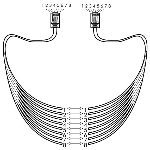
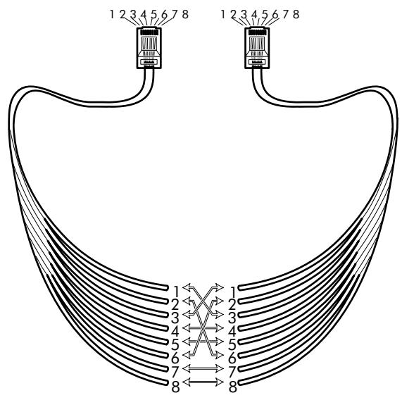
B.3 LAN Cables Layout
Straight-through LAN cable
Straight-through LAN cables with the following layout are applicable for interconnecting Ethernet ports, and ATMF-25.6 ports:
Crossover LAN cable
Crossover LAN cables with the following layout are applicable for interconnecting Ethernet ports, and ATMF-25.6 ports:
B.4 Physical Specifications
Physical dimensions 210mm W x 185mm D x 35mm H
Operating environment Temperature: 5^ C to 40^ C (40F to 105F)
Humidity: 20% to 80%
Power requirements AC voltage: 100 to 120VAC 220 to 240VAC
DC voltage: 9V/1A
Frequency: 50/60 Hz
Power consumption: 7W_
Ports characteristics The external ports on the back panel are classified as follows:
DC input port
SELV circuit (*)
10Base-T/MDI-X
SELV circuit
ATMF-25
SELV circuit
Line DSL port
TNV-3 circuit**
() Safety Electronic Low Voltage (SELV)
(^*) Telecommunication Network Voltage (TNV) Category 3
B.5 ADSL Specifications
ADSL modem specifications
ADSL data rates
- Downstream user (payload) data rates: Up to 8Mbit/s, depending on provisioning
- Upstream user (payload) data rates: Up to 1Mbit/s, depending on provisioning
ADSL/POTS standards compliancy
Full rate ANSI T1.413 Issue 2
ITU(*) G.DMT (Full rate ITU G.992.1 Annex A)
ITU G.LITE (Lite rate ITU G.992.2)
ITU G.Handshake (Automode ITU G.994.1)
ADSL/ISDN standards compliancy
ETSI TS 101 388
ITU G.Handshake (Automode ITU G.994.1)
(*) International Telecommunication Union (ITU)
AppendixC
Speed Touch Default Assignments
In this chapter
| Topic | See |
| General Defaults | C.1 |
| Connection Service/ATM Encapsulation Defaults | C.2 |
C.1 General Defaults
STHome IP address 10.0.0.138
STHome DNS name SpeedTouch
STHome Domain name lan
STHome DNS server Active
STHome DHCP server Disabled
STHome Master Enabled Firewall
STHome system Not set password
C.2 Connection Service/ATM Encapsulation Defaults
ATMF-25.6 port (optional)
| VPI | VCI | Upper Layer Protocols | Service channel |
| 0 ...7 | 0 ...511 | ADSL/ATMF-25.6 X-connect | End-User defined |
Ethernet port
| VPI (*) | VCI | Upper Layer Protocols | Service channel |
| 0/8 | 35 | Bridge AAL5/RFC1483/Bridged RFC1483 LLC/SNAP for Bridged PDUs (FCS not preserved) | Transparent Bridging Bridged PPPoE |
| 0/8 | 36 | ||
| 0/8 | 37 | ||
| 0/8 | 38 | ||
| 0/8 | 48 | PPTP AAL5/RFC2364 RFC2364 VC-MUX for PPP PDUs | PPPDo-to-PPTP Relaying |
| 0/8 | 49 | ||
| 0/8 | 50 | ||
| 0/8 | 51 |
(*) The default VP = 0 setting can only be applicable for the single Ethernet model.
Control channels
| VPI | VCI | Upper Layer Protocols | Service channel |
| 0 | 21 | - | DSL/ATM Loopback channel |
| 1 | 21 | ||
| 15 | 16 | AAL5/SNMP | SNMP/ASAM agent communication channel for Alcatel ASAM |
| 15 | 64 | AAL5/TFTP | Software TFTP download channel |
AppendixD
Safety and Agency Regulatory Notices
Aim of this appendix
This appendix provides basic Safety Information on Alcatel's Speed Touch™ product.
Prior to using the Speed Touch™ product, read this appendix carefully.
Reading all instructions
Follow all warnings and instructions marked on the product.
In this appendix
This chapter covers the following topics:
| Topic | See |
| Safety Instructions | D.1 |
| European Declaration of Conformity | D.2 |
| Radio Frequency Interference Statement | D.3 |
| Canadian Class B Notice | D.4 |

STORE THESE INSTRUCTIONS CAREFULLY

Directive
Unless expressly and unambiguously approved by Alcatel, you may not:
disassemble, de-compile, reverse engineer, trace or otherwise analyse the equipment, its content, operation, or functionality, or otherwise attempt to derive source code (or the underlying ideas, algorithms, structure or organization) from the equipment or from any other information provided by Alcatel, except to the extent that this restriction is expressly prohibited by local law;
copy, rent, loan, re-sell, sublicense, or otherwise transfer or distribute the equipment to others;
modify, adapt or create a derivative work of the equipment;
remove from any copies of the equipment any product identification, copyright or other notices;
disseminate performance information or analysis (including, without limitation, benchmarks) from any source relating to the equipment.
Such acts not expressly approved by Alcatel will result in the loss of product warranty and will invalidate the user's authority to operate this equipment.
D.1 Safety Instructions
Climatic conditions
The Speed Touch™ product equipment is intended for:
In-house stationary desktop use; the maximum ambient temperature may not exceed 40^ (104°F).
It must not be mounted in a location exposed to direct or excessive solar and/or heat radiation.
It must not be exposed to heat trap conditions and must not be subjected to water or condensation.
It must be installed in a Pollution Degree 2 environment.
Cleaning
Unplug this product from the wall outlet before cleaning. Do not use liquid cleaners or aerosol cleaners. Use a damp cloth for cleaning.
Water and moisture
Do not use this product near water, for example, near a bathtub, wash bowl, kitchen sink, laundry tub, in a wet basement or near a swimming pool.
Power supply adapter
The Speed Touch™ product comes with a portable power supply adapter.
Due to the special characteristics of the output of the class II AC adaptor, only use the models or equivalent listed in the power adapter table in this User's Guide.
Power sources
The powering of this product must adhere to the power specifications indicated on the marking labels. If you are unsure of the type of power supply to your home, consult your product dealer or local power company.
The mains socket outlet must be close to the equipment and easily accessible.
The Speed Touch™ product equipment is not intended to be connected to an IT-type power system.
Power cord protection
Do not allow anything to rest on the power cord. Do not locate this product where the cord will be subject to persons walking on it.
Overloading
Do not overload wall (mains) outlets and extension cords as this increases the risk of fire or electric shock.
Servicing
To reduce the risk of electric shock, do not disassemble this product. None of its internal parts are user-replaceable; therefore, there is no reason to access the interior. Opening or removing covers may expose you to dangerous voltages. Incorrect reassembly could cause electric shock if the appliance is subsequently used.
If service or repair work is required, take it to a qualified service dealer.
Damage requiring service
Unplug this product from the wall outlet and refer servicing to qualified service personnel under the following conditions:
When the power supply cord or plug is damaged or frayed.
If liquid has been spilled into the product.
If the product has been exposed to rain or water.
If the product does not operate normally.
If the product has been dropped or damaged in any way.
If the product exhibits a distinct change in performance.
Modem/Telephone use
Avoid using a modem/telephone (other than a cordless type) during an electric storm. There is a slight risk of electric shock caused by lightning.
Do not use the telephone to report a gas leak in the vicinity of the leak.
If telephone service is required on the same line, a central splitter, or distributed filter(s) must be installed for optimal DSL performance.
Depending on your DSL configuration and type of splitter/filters, installation must be carried out by qualified service personnel.
Consult your telephone service company or DSL service provider for instructions.
Modifications
Changes or modifications not expressly approved by Alcatel could invalidate the users authority to operate this equipment.

STORE THESE INSTRUCTIONS CAREFULLY

D.2 European Community Declaration of Conformity

Products with the C€ marking comply with both EMC and Low Voltage Directives issued by the Commission of the European Community.
EC Declaration of Conformity
A copy of the European Community Declaration of Conformity is provided in your Speed Touch™ product shipping box.
D.3 Radio Frequency Interference Statement
This device has been tested and found to comply with the limits for a Class B digital device, pursuant to Part 15 of the FCC Rules. These limits are designed to provide reasonable protection against such interference in a residential installation. This equipment generates, uses and can radiate radio frequency energy. If not installed and used in accordance with the instructions, it may cause harmful interference to radio communications. However, there is no guarantee that interference will not occur in a particular installation. If this equipment does cause harmful interference to radio or television reception, which can be determined by turning the equipment ON and OFF, the user is encouraged to try correct the interference by one or more of the following measures:
Reorient or relocate the receiving antenna
Increase the separation between the equipment and receiver
Connect the equipment into an outlet on a circuit different from that to which the receiver is connected
Consult the dealer or an experienced radio/television technician for help.
This equipment complies with Part 68 of the FCC Rules. On the back of this equipment is a label that contains, among other information, the FCC certification number (FCC ID) and Ringer Equivalence Number (REN) for this equipment. If requested, this information must be provided to the telephone company.
An FCC compliant telephone cord and modular plug is provided with this equipment. This equipment is designed to be connected to the telephone network or premises wiring using a compatible modular jack that is Part 68 compliant.
The Ringer Equivalence Number (REN) is used to determine the quantity of devices that may be connected to the telephone line. Excessive RENs on the telephone line may result in the devices not ringing in response to an incoming call. Typically, the sum of RENs should not exceed five (5.0). To be certain of the number of devices that may be connected to a line (as determined by the total RENs) contact the local telephone company.
If this equipment causes harm to the telephone network, the telephone company will notify you in advance that temporary discontinuance of service may be required. But if advance notice is not practical, the telephone company will notify the customer as soon as possible. Also you will be advised of your right to file a compliant with the FCC if you believe it is necessary.
The telephone company may make changes to its facilities, equipment, operations or procedures that could affect the operation of the equipment. If this happens the telephone company will provide advance notice so you can make the necessary modifications to maintain uninterrupted service. If the equipment is causing harm to the telephone network, the telephone company may request that you disconnect the equipment until the problem is resolved. Connection to party lines is subject to state tariffs (contact the state public utility commission, public service commission or corporation commission for information).
No repairs can be performed by the customer, if you experience trouble with this equipment for repair or warranty information, please contact: (919) 850-1231 for locations in North America.
D.4 Canadian DOC Class B Notice
Notification of Canadian RF Interference Statements
This digital apparatus does not exceed the Class B limits for radio noise emissions from digital apparatus as set out in the radio interference regulations of the Canadian Department of Communication.