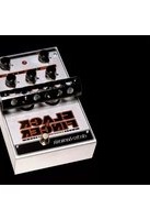
Black Finger - Audio effect pedal Electro Harmonix - Free user manual and instructions
Find the device manual for free Black Finger Electro Harmonix in PDF.


| Product Type | Compressor/Sustainer Pedal |
| Model | Black Finger |
| Brand | Electro Harmonix |
| Controls | Sustain, Volume, Blend, Compression Ratio (Sustain), Output Level, On/Off Footswitch |
| Input Impedance | 1 MΩ |
| Output Impedance | 600 Ω |
| Power Supply | 9V DC (center negative) or 9V battery |
| Current Consumption | 8 mA |
| Dimensions (W x D x H) | 2.75 x 4.5 x 2.125 inches (70 x 114 x 54 mm) |
| Weight | 0.6 lbs (272 g) |
| Color | Black with gold lettering |
| Construction | Die-cast zinc chassis |
| True Bypass | Yes |
| LED Indicator | Yes (power/effect on) |
| Inputs/Outputs | 1/4" jack input and output |
| Warranty | 1 year limited |
Frequently Asked Questions - Black Finger Electro Harmonix
User questions about Black Finger Electro Harmonix
0 question about this device. Answer the ones you know or ask your own.
Ask a new question about this device
Download the instructions for your Audio effect pedal in PDF format for free! Find your manual Black Finger - Electro Harmonix and take your electronic device back in hand. On this page are published all the documents necessary for the use of your device. Black Finger by Electro Harmonix.
USER MANUAL Black Finger Electro Harmonix
All-tube Optical Compressor
- OPERATING INSTUCTIONS -
Congratulations on your purchase of the Black Finger! The Black Finger is a warm sounding compressor pedal useful for both guitar and bass, as well as for home recording. This pedal features an all-tube signal path using two premium 12AX7EH vacuum tubes. Carefully reading these instructions will ensure that you will get the most out of your Black Finger.
Included with the Black Finger is a unique 12VAC/1000mA adapter. Use only the adapter supplied. Using any other adapter can cause harm to you, the Black Finger and the adapter.
WARNING: There are extremely high voltages in the Black Finger even when it is unplugged – DO NOT OPEN THE BLACK FINGER.
Optical compressors work by treating an incoming signal with an optically controlled attenuator (a type of volume control) comprised of a fixed resistor and a shunt optocoupled photocell. Because this attenuator is “passive”—as opposed to the more common “active” AGC (Automatic Gain Control) compressor circuits—it doesn’t add an electronic signature to the signal, thus preserving the tone and character of the original sound. Some gain is needed to adjust the output level so that it matches the original level, and this is accomplished with an all-tube fixed gain pre-amp circuit. In general, compressors are used to sustain melody lines, minimize changes in signal level, or add a “forward” percussive effect to instruments or drums.
- CONTROLS -
COMPRESS Knob— Varies the amount of compression from minimum (counterclockwise) to maximum (clockwise).
LAMP/LED Switch— Selects the light source to drive the optical attenuator. The LED is very fast and flat in frequency content. Choose this setting for straight-ahead compression effects and sustain. Choose LAMP for a slow attack and a reduced compression on the treble content. This is great for funk chord playing, voice and keyboards.
SQSH/NORM Switch— Selects between normal attack and a “squashed” long attack time for the attenuator. This directly affects only the LAMP setting but you will see a reduction in compression if you leave SQSH on while in LED mode.
PRE-GAIN Knob—Adjusts the amount of signal fed to the attenuator. With this knob turned toward the minimum (counter-clockwise) position, less of the signal will pass the compression threshold. This is one way to dial in less effect. More signal in will mean that more of the signal will pass the compression threshold. This will maximize the effect when the COMPRESS Knob is turned up, or clip/overdrive the circuit if the COMPRESS Knob is turned down.
POST-GAIN Knob—Adjusts the level of the OUTPUT signal.
LEVEL LED— Gives a visual indication of the gain reduction caused by the compressor. The brighter the LED is, the greater the compression.
STATUS LED—Lights up when the Black Finger effect is engaged. If the STATUS led is off, the unit is in true bypass mode. The footswitch engages/disengages the effect.
- WARRANTY INFORMATION -
Please register online at http://www.ehx.com/product-registration or complete and return the enclosed warranty card within 10 days of purchase. Electro-Harmonix will repair or replace, at its discretion, a product that fails to operate due to defects in materials or workmanship for a period of one year from date of purchase. This applies only to original purchasers who have bought their product from an authorized Electro-Harmonix retailer. Repaired or replaced units will then be warranted for the unexpired portion of the original warranty term.
If you should need to return your unit for service within the warranty period, please contact the appropriate office listed below. Customers outside the regions listed below, please contact EHX Customer Service for information on warranty repairs at info@ehx.com or +1-718-937-8300. USA and Canadian customers: please obtain a Return Authorization Number (RA#) from EHX Customer Service before returning your product. Include with your returned unit: a written description of the problem as well as your name, address, telephone number, e-mail address, and RA#; and a copy of your receipt clearly showing the purchase date.
United States & Canada
EHX CUSTOMER SERVICE
ELECTRO-HARMONIX
c/o NEW SENSOR CORP.
47-50 33RD STREET
LONG ISLAND CITY, NY 11101
Tel: 718-937-8300
Email: info@ehx.com
Europe
JOHN WILLIAMS
ELECTRO-HARMONIX UK
13 CWMDONKIN TERRACE
SWANSEA SA2 0RQ
UNITED KINGDOM
Tel: +44 179 247 3258
Email: electroharmonixuk@virginmedia.com
This warranty gives a purchaser specific legal rights. A purchaser may have even greater rights depending upon the laws of the jurisdiction within which the product was purchased.
To hear demos on all EHX pedals visit us on the web at www.ehx.com
Email us at info@ehx.com
- FCC COMPLIANCE -
This device complies with part 15 of the FCC Rules. Operation is subject to the following two conditions: (1) This device may not cause harmful interference, and (2) this device must accept any interference received, including interference that may cause undesired operation. If the device is not installed and used in accordance with the instructions, it may cause harmful interference to radio communications and void the user's authority to guarantee the equipment.
Note: This equipment has been tested and found to comply with the limits for a Class B digital device, pursuant to part 15 of the FCC Rules. These limits are designed to provide reasonable protection against harmful interference in a residential installation. This equipment generates, uses and can radiate radio frequency energy and, if not installed and used in accordance with the instructions, may cause harmful interference to radio communications. However, there is no guarantee that interference will not occur in a particular installation. If this equipment does cause harmful interference to radio or television reception, which can be determined by turning the equipment off and on, the user is encouraged to try to correct the interference by one or more of the following measures:
• Reorient or relocate the receiving antenna.
- Increase the separation between the equipment and receiver.
- Connect the equipment into an outlet on a circuit different from that to which the receiver is connected.
- Consult the dealer or an experienced radio/TV technician for help.
Modifications not expressly approved by the manufacturer could void the user's authority to operate the equipment under FCC rules.



Brand : Electro Harmonix
Model : Black Finger
Category : Audio effect pedal