
WGCXT1RJ5NB - Network Socket HAGER - Free user manual and instructions
Find the device manual for free WGCXT1RJ5NB HAGER in PDF.


| Product Type | Wireless Doorbell/Chime |
| Brand | Hager |
| Model | WGCXT1RJ5NB |
| Power Supply | 2 x LR03 (AAA) Alkaline batteries, 1.5V |
| Dimensions (Receiver) | 80 x 60 x 30 mm |
| Weight (Receiver) | 100 g |
| Battery Life | Approx. 12 months under normal use |
| Operating Frequency | 433.92 MHz |
| Range | Up to 100 m in open field |
| Number of Melodies | 52 selectable ringtones |
| Volume Control | Adjustable, 4 levels + mute |
| Indicator Light | Red LED flash upon button press |
| Button (Push) | Weatherproof, IP44 rating |
| Mounting | Wall mount (receiver) with screws or adhesive tape |
| Maintenance | Wipe with a dry cloth; replace batteries when low |
| Safety | Low voltage; no sharp edges; indoor use for receiver |
| Spare Parts | None available; batteries are replaceable |
| Repairability | Not user-serviceable; contact Hager support for issues |
| Warranty | 2 years from purchase date |
| Package Contents | Receiver, push button, batteries, mounting kit, manual |
Frequently Asked Questions - WGCXT1RJ5NB HAGER
User questions about WGCXT1RJ5NB HAGER
0 question about this device. Answer the ones you know or ask your own.
Ask a new question about this device
Download the instructions for your Network Socket in PDF format for free! Find your manual WGCXT1RJ5NB - HAGER and take your electronic device back in hand. On this page are published all the documents necessary for the use of your device. WGCXT1RJ5NB by HAGER.
USER MANUAL WGCXT1RJ5NB HAGER
Electrical equipment must only be installed and assembled by a qualified electrician in accordance with the relevant installation standards, regulations, directives and safety and accident prevention directives of the country.
Failure to comply with these installation instructions may result in damage to the device, fire or other hazards.
Function
The RJ45 outlets are used for data transmission in local area networks. The RJ11 outlets are designed for telephone and data applications. Each jack is equipped with a dust protection slider.
Correct use
- For the flush-mounted installation in standard wall boxes (recommended wall box depth ≥ 35 mm).
- Only suitable for use in indoor areas with no drip and no spray water.
Technical data
RJ45 outlets
Voltage proof (contact-to-contact): 1000 V DC or AC peak
Current rating: 0.75 A
Insulation resistance: ≥ 500 M Ω at 100 V DC
Signal contact resistance: ≤ 20 mΩ
Type of connection: IDC terminals
Design: according to IEC 60603-7
Colour code A and B: according to TIA/EIA 568-B.2
RJ45 Cat.5e modules
Transmission bandwidth: max. 100 MHz
Conductor ∅ (solid): 0.51 ... 0.64 mm (AWG 24-22)
Cat.5e, unshielded (UTP): according to ISO/IEC 11801
RJ45 Cat.6 modules
Transmission bandwidth: max. 250 MHz
Conductor ∅ (solid): 0.51 ... 0.64 mm (AWG 24-22)
Cat.6, unshielded (UTP): according to ISO/IEC 11801, 2nd edition
RJ45 Cat.6A modules
Transmission bandwidth: max. 500 MHz
Conductor ∅ (solid): 0.41 ... 0.64 mm (AWG 26-22)
Cat.6A, unshielded (UTP): according to ISO/IEC 11801, edition 2.2
RJ11 outlet
Compliance: YD/T 577
Information for electricians
Installation and electrical connection
Preparing the device for installation
(for example "RJ11 + RJ45 outlet")
1A

Hager Muse
Hager Inspire1B

- Carefully loosen the frame on the notches with a flat-blade screwdriver. Lift up and remove the frame (1A/1B).
■ Hager Inspire: Remove the cover plate also with a flat-blade screwdriver (1B).
Connecting the RJ45 data module
■ Remove the cover plate of the data module with a flat-blade screwdriver.
2A
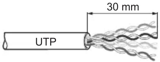
- Strip 30 mm of cable jacket (2A).
■ Position and terminate first pair according to colour code A or B:
RJ45 pin assignment TIA/EIA 568B TIA/EIA 568A
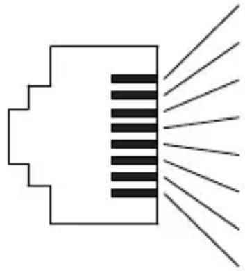 | 1 white/orange white/green | |
| 2 orange green | ||
| 3 white/green white/orange | ||
| 4 blue blue | ||
| 5 white/blue white/blue | ||
| 6 green orange | ||
| 7 white/brown white/brown | ||
| 8 brown brown |
As with the first pair position and terminate each subsequent pair one at a time until termination is complete.
- Fix the cover plate back to the module.
Connecting the RJ11 telephone module
3A

- Strip 10 mm of cable jacket (3A).
■ Position first pair according to colour code:
RJ11 pin assignment
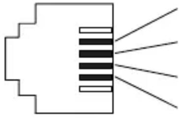 | 2 blue/white |
| 3 white/blue | |
| 4 white/red | |
| 5 red/white |
- Fix the cover plate back to the module.

Checking of the installation:
A functional test of the installation should be made for each data or telephone outlet.
Installing the device into the wall box
(for example "RJ11 + RJ45 outlet")
4
natural_image
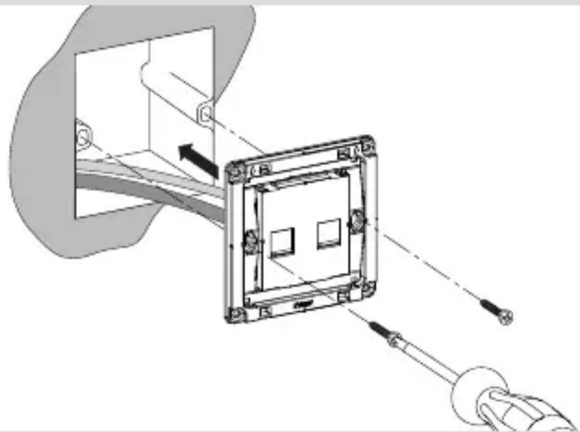
Technical diagram of a mechanical assembly with a bracket and tool, showing no text or symbols■ After wiring, fix the device with the two screws attached into the wall box (4).
Assembling the covers
(for example "RJ11 + RJ45 outlet")
5A

Hager Muse
5B

Hager Inspire
■ Hager Muse: Snap the frame onto the device (5A).
■ Hager Inspire: Place the cover plate in the correct position and fix with frame (5B).
2-5gang frames are available for multiple combinations.


- Function
- Correct use
- Technical data
- RJ45 outlets
- RJ45 Cat.5e modules
- RJ45 Cat.6 modules
- RJ45 Cat.6A modules
- RJ11 outlet
- Information for electricians
- Installation and electrical connection
- Preparing the device for installation
- Connecting the RJ45 data module
- Connecting the RJ11 telephone module
- Installing the device into the wall box
- Assembling the covers
Brand : HAGER
Model : WGCXT1RJ5NB
Category : Network Socket