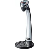
Vi TAP-2H - Ice Maker Vivreau - Free user manual and instructions
Find the device manual for free Vi TAP-2H Vivreau in PDF.


| Product Type | Undercounter Ice Maker |
| Model | Vi TAP-2H |
| Brand | Vivreau |
| Dimensions (W x D x H) | 380 mm x 420 mm x 590 mm |
| Weight | 18 kg |
| Power Supply | 220-240 V, 50 Hz, 1.5 A |
| Ice Production Capacity | 12 kg per day |
| Ice Storage Capacity | 2.5 kg |
| Ice Cube Size | Bullet or cube (selectable) |
| Cooling System | Compressor with R600a refrigerant |
| Noise Level | ≤ 45 dB(A) |
| Material | Stainless steel body with transparent window |
| Control Panel | Touch buttons with LED display |
| Indicators | Full ice bin, water shortage, cleaning reminder |
| Water Supply | Automatic water fill (direct connection) or manual refill |
| Cleaning | Self-cleaning cycle with descaling function |
| Safety Features | Overheat protection, child lock, automatic shut-off when door open |
| Installation | Freestanding or undercounter (ventilation required) |
| Spare Parts Availability | Ice scoop, water filters, cleaning kits available |
| Warranty | 2 years (parts and labor) |
Frequently Asked Questions - Vi TAP-2H Vivreau
User questions about Vi TAP-2H Vivreau
0 question about this device. Answer the ones you know or ask your own.
Ask a new question about this device
Download the instructions for your Ice Maker in PDF format for free! Find your manual Vi TAP-2H - Vivreau and take your electronic device back in hand. On this page are published all the documents necessary for the use of your device. Vi TAP-2H by Vivreau.
USER MANUAL Vi TAP-2H Vivreau
natural_image
Modern water dispenser with clear glass and digital display, no visible text or symbols on the device itself
Intertek


natural_image
Abstract water splash illustration with bubbles and splashes (no text or symbols)i IMPORTANT
The information contained in this manual is specific to your system. It is IMPORTANT you READ, FOLLOW and UNDERSTAND the instructions given.
This manual and all material provided with your system should be retained in a convenient location for future reference.
Contact Vivreau if you have any questions regarding the information contained in this manual.
© 2017 Vivreau USA
All rights reserved.
Any and all information contained within this document is subject to change without prior notice.
TABLE OF CONTENTS
SAFETY PRECAUTIONS ....5
GENERAL INFORMATION....7
TECHNICAL SPECIFICATIONS....9
PRE-INSTALLATION REQUIREMENTS....11
OPERATING INSTRUCTIONS....13
MAINTENANCE....17
TROUBLESHOOTING....23
SAFETY PRECAUTIONS

IMPORTANT
This manual is intended for use only by personnel trained in the operation of the Vivreau ViTAP Dispensing System.
⚠ WARNING Improper installation, adjustment, alteration, service or maintenance can cause property damage, injury, or death. Read the installation, operating, and maintenance instructions thoroughly before installing, operating, or maintaining this equipment.
⚠ WARNING Keep the area around the unit clear of any combustible materials.
⚠ WARNING Do not store or use gasoline or other flammable vapors or liquids in the vicinity of this or any other unit.

IMPORTANT
Carefully read, understand and follow all safety instructions in this manual and safety labels on the unit.
- Keep safety labels in good condition and replace missing or damaged items.
- Learn how to operate the unit and how to use the controls properly.
- Do not let anyone operate the unit without proper training.
- In the event of a power failure, do not attempt to operate this unit.
- Keep unit in proper working condition and do not allow unauthorized modifications to the unit.
⚠ WARNING Only trained and certified electrical, plumbing and refrigeration technicians should service this unit.
⚠ WARNING ALL WIRING AND PLUMBING MUST CONFORM TO NATIONAL AND LOCAL CODES. FAILURE TO COMPLY COULD RESULT IN SERIOUS INJURY, DEATH OR EQUIPMENT DAMAGE.
SAFETY PRECAUTIONS
This unit has been specifically designed to provide protection against personal injury.
To ensure continued protection observe the following:
⚠ WARNING Disconnect power to the unit before servicing. Follow all LOCKOUT/TAGOUT procedures. Verify power to the unit is OFF and disconnected before any work is performed. Failure to do so could result in serious injury, death or equipment damage.
- To protect against electric shock, do not immerse power cord in water or other liquid.
- To prevent damage to the power cord, do not allow cord to hang over the edge of a table or counter, or come in contact with hot surfaces.
- Isolate unit from power supply (unplug or turn OFF breaker) and turn OFF the water supply when not in use and before cleaning.
- Allow Boiler (if supplied) to cool before removing any components.
- The use of spare parts and accessories not recommended by Vivreau may cause damage and/or injuries.
- Do not operate any unit with damaged cords, plugs, or after the unit malfunctions or has been damaged in any manner.
- Do not use outdoors.
- Do not place on or near a hot gas or electric burner.
- Do not use the unit for anything other than its intended use.
- Save these instructions.
GENERAL INFORMATION
INFORMATION FOR THE READER
To find specific topics of interest quickly, refer to the Table of Contents at the beginning of this manual.
This manual is solely for the use of personnel trained in the operation of the ViVreau ViTAP Dispensing System only.
PURPOSE OF THE MANUAL
- Vivreau has produced this manual to provide necessary information to qualified and authorized personnel for the safe and proper installation, operation, and maintenance of the Vivreau ViTAP-2, ViTAP-2H and ViTAP-2HD Dispensing Systems.
- Information contained in this manual will help prevent risks to health and safety, and the risk of economic losses.
- Keep this manual in a clearly identified and safe place throughout the working life of the unit, so that it will always be available as needed.
- The manufacturer reserves the right to make modifications to the unit without any obligation to provide prior notice.
- A number of symbols have been used to highlight particularly important parts of the text or important specifications. Their meaning is as defined below.
DANGER
INDICATES AN IMMINENTLY HAZARDOUS SITUATION WHICH, IF NOT AVOIDED, WILL RESULT IN DEATH OR SERIOUS INJURY.
WARNING
Indicates that suitable procedures must be adopted to avoid putting people's health and safety at risk or causing economic losses.
CAUTION
Indicates a potentially hazardous situation which, if not avoided, may result in property damage, minor or moderate injury.
i IMPORTANT
Indicates important technical information which must not be overlooked.
TECHNICAL SPECIFICATIONS
GENERAL DESCRIPTION
The Vivreau ViTAP-2 (H/HD) is a self-service Water Dispensing System designed for under-counter installation with the Dispenser Head mounted to the countertop directly above the unit.
The system is made up of several components (depending on model) that will fit under a standard base-cabinet section that is 30" wide (min.)
| Dispensing Specifications | ||||
| Description Specification | ViTap-2 ViTap-2H ViTap-2HD | |||
| Chilled still water T=18 °F @ 15.8 gal/h | √ √ | √ | ||
| Chilled sparkling water T=18 °F @ 15.8 gal/h | √ √ | √ | ||
| Hot water 203°F NA | √ | √ | ||
| Hot water, immediate dispense | 0.5 gal/h | NA | √ | √ |
| Hot water, storage capacity | 1.2 gal. | NA | √ | √ |
| Water Pressure at Dispensing Head | 5 PSI | √ √ | √ | |
| Operating Conditions | ||||
| Description Specification | ViTap-2 ViTap-2H ViTap-2HD | |||
| Temperature | 60 – 90°F | √ √ | √ | |
| Relative Humidity | 60% (max.) | √ √ | √ | |
| Water Supply Requirements | ||||
| Description | Requirements | ViTap-2 ViT | Tap-2H ViTap-2HD | |
| FNPT connection with Ball Valve | 1/2" | √ √ | √ | |
| PSI (min.) | 50 | √ √ | √ | |
| GPH (min.) | 80 | √ √ | √ | |
| Temperature (max.) | 60°F | √ √ | √ | |
| CO2 Operating Pressure | ||||
| Description | Requirements | ViTap-2 ViT | ap-2H ViTap-2HD | |
| Pressure | 65 – 70 PSI | √ √ | √ | |
| Supply pressure (Bulk System) | 100 PSI (min.) | √ √ | √ | |
| Dispensing Head Specifications | ||||
| Description | Requirements | ViTap-2 ViT | ap-2H ViTap-2HD | |
| Height | 13" | √ √ | √ | |
| Distance Nozzle to Drip Tray | 9.6" | √ √ | √ | |
| Weight | 7.4 lb | √ √ | √ | |
| Cooler/Carbonator Specifications | ||||
| Description Specification | ViTap-2 ViTap-2H ViTap-2HD | |||
| Width 15" | √ √ | √ | ||
| Height 20" | √ √ | √ | ||
| Depth 18.5" | √ √ | √ | ||
| Weight 39.6 lb. | √ √ | √ | ||
| Voltage | 110/120 VAC/60 Hz | √ √ | √ | |
| Amperage | 11A | √ √ | √ | |
| Boiler Specifications | ||||
| Description Specification | ViTap-2 ViTap-2H ViTap-2HD | |||
| Width 5.25" NA | √ | √ | ||
| Height | 22.0" | NA | √ | √ |
| Depth | 15.75" | NA | √ | √ |
| Weight | 30.8 lb | NA | √ | √ |
| Voltage | 110/120 VAC/60 Hz | NA | √ | NA |
| 230/240 VAC/60 Hz | NA | NA | √ | |
| Amperage | 13A | NA | √ | NA |
| 11A | NA | NA | √ | |
PRE-INSTALLATION REQUIREMENTS
PRE-INSTALLATION
Below are the services required to be in place prior to the installation of the Vivreau ViTAP Dispensing System. If you have any questions regarding these or other services, please contact Vivreau Service Toll-Free at 877-999-1044.
WATER SUPPLY
A potable 1/2" cold water supply terminating in a 1/2" Ball Valve, 1/2" female pipe thread.

IMPORTANT
Ball Valve must be accessible for service and installation.
Minimum Water Pressure: 50 PSI
Minimum Water Flow: 80 gallons per hour

IMPORTANT
The Vivreau ViTAP Dispensing System incorporates backflow prevention. Any additional backflow devices required by State or Local Code must also be supplied by the customer prior to installation. There must not be any other Filters/Pre-Filters inline before the unit.
ELECTRICAL OUTLET
Model ViTAP-2
(1) 15 Amp Electrical Recepticle (NEMA 5-15R) 120V, 60 Hz (11 Amps)
Model ViTAP-2H
(1) 15 Amp Electrical Recepticle (NEMA 5-15R) 120V, 60 Hz (11 Amps)
(1) 20 Amp Electrical Recepticle (NEMA 5-20R) 120V, 60 Hz (13 Amps)
Model ViTAP-2HD
(1) 15 Amp Electrical Recepticle (NEMA 5-15R) 120V, 60 Hz (11 Amps)
(1) 20 Amp Electrical Recepticle (NEMA L6-20R) 230V, 60 Hz (11 Amps)
NOTE: ViTAP-2HD will not operate on 208 VAC.
All outlets must be mounted high in the cabinet to avoid accidental contact with water.
CO _2
CO _2 Cylinder (Customer supplied) - Size should be selected based on available space.
NOTE: If connecting to a bulk or existing CO_2 system, a CO_2 line terminating at a 1/4" Barbed Shutoff Valve must be available within 40" of the unit with 100 PSI minimum pressure.
DRIP TRAY AND DISPENSING HEAD CUTOUTS
Cut out the holes for the Drip Tray and Dispensing Head per the supplied template.
NOTE: The Dispensing Head must be mounted on the work surface directly above the Chiller/Carbonator.
DRIP TRAY DRAIN
Drip Tray must be plumbed to a drain. Customer will need to supply a drain according to State and Local Codes. Drain must be at least 1-1/4" ID.
LOCATION OF SERVICES
All services must be accessible for installation and service. Ensure all services are kept within 40" of the ViTAP Dispensing System.
Water Shutoff Valve to be located at low level. Ensure there is sufficient room for a 6" long fitting to be connected to the Water Shutoff Valve.
Top of drain should be located between 12" and 18" from floor level.
SHIPPING DAMAGE/MISSING PARTS
Unpack and inspect the unit for shipping damage and/or missing parts. If any damage or missing parts are found, contact Vivreau Service Toll-Free at 877-999-1044 and report the missing or damaged parts.
LOCATION
A suitable location should be chosen within 40" of the electrical and water supply connections.
| Installation Clearance for Chiller Unit | |
| Left side 2" | |
| Right side 2" | |
| Rear 2" | |
| Above Open | |
Do not obstruct air vents.
Install the system on a firm, level floor or base.
VENTILATION
If the system is to be installed in an enclosed space or in a cabinet, adequate ventilation must be provided. Ventilation must be at the top and bottom of the enclosure for proper air flow.
⚠️CAUTION Failure to provide adequate ventilation will cause system failure.
This unit is to be installed indoors only.
DISPENSING HEAD
The Dispensing Head with Integral Drip Tray is installed into a countertop directly over the Chiller/Carbonator and Boiler (if equipped) using the supplied template.

Dispensing Head Template

Ventilation Options
OPERATING INSTRUCTIONS
The ViTAP Dispensing System has been designed for ease of use.

IMPORTANT
Before operating the ViTAP Dispensing System, make sure the water supply is turned ON and the unit is plugged in.
BEFORE USE
A LWAYS sanitize your hands.
A LWAYS wear hygienic gloves.
ALWAYS remove anti-bacterial cling film from the Dispensing Head.
A LWAYS wipe Dispensing Head, Nozzles, Drip Tray and cabinet work-surface with anti-bacterial wipes.
LED DISPLAY PANEL
The LED Display Panel is located on the front panel of the Chiller/Carbonator.
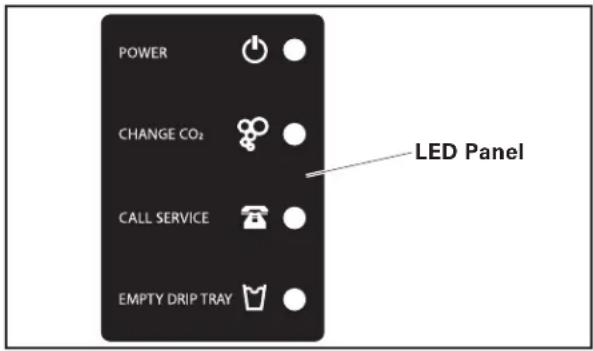
Dispensing Head System LED Display Panel
POWER: When the Dispensing Head System is plugged in and turned ON, a Blue LED will be illuminated.
CHANGE CO 2 : When the CO 2 supply is low, a Red LED will illuminate and the unit will beep; alerting you to change the CO _2 Cylinder.
CALL SERVICE: If there is a problem, a Red LED will illuminate and the unit will beep. Please contact Vivreau Service Toll-Free at 877-999-1044 immediately.
EMPTY DRIP TRAY: (Not Activated on this Unit): When the Drip Tray Container is FULL, a Red LED will illuminate and the unit will beep; alerting you to empty the Drip Tray Container located just inside the cabinet front door or below the Dispensing Head System.
DISPENSING

IMPORTANT
Before operating the ViTap Dispensing System, make sure the Water Supply Valve is open and the unit is plugged in.
DISPENSING
Before operating the ViTAP Dispensing System, make sure the Water Supply Valve is open and the Chiller (and Boiler, if supplied) is plugged in.
Place appropriate container on Drip Tray beneath the Dispensing Head.
Chilled Still Water
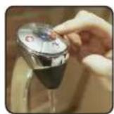
Press and Hold the Blue Button to dispense water. Release the button when filled.

natural_image
Illustration of a hand holding a circular device with icons for food, beverage, and kitchen items (no text or symbols)Dispensing Chilled Still Water
Chilled Sparkling Water
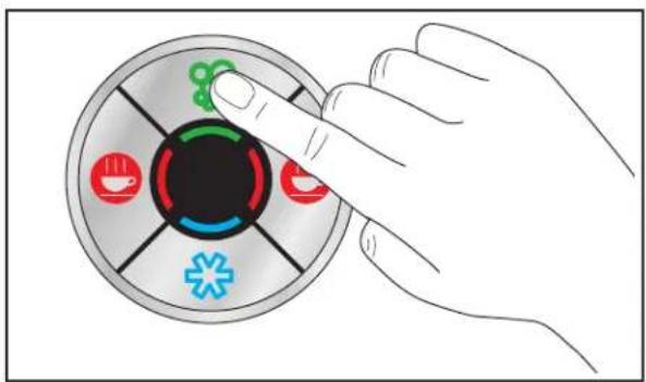
Press and Hold the Green Button to dispense water. Release the button when filled.

natural_image
Hand interacting with a circular device showing icons for coffee, beer, and medical symbols (no text or labels)Dispensing Chilled Sparkling Water
Hot Water (if supplied)
As a safety feature, to dispense Hot Water, Touch and Release either Red Button, then Press and Hold the opposite side Red Button within 3 seconds.
Release the button when filled.

Dispensing Hot Water
⚠ WARNING Water is Hot! Do not place hands or other body parts beneath Dispensing Head when dispensing hot water.
AFTER DAILY USE
Remove Dispensing Nozzle and place in a container of Sanitizing Solution.
Leave Nozzle in Sanitizing Solution for a minimum of 4 hours.
Ensure protective gloves are worn when in contact with Sanitizing Solution.
Wipe Dispensing Head, Drip Tray and countertop surface with anti-bacterial wipes and sanitizing spray.
Wrap Dispensing Head with plastic film.
To return the Dispensing Head System to service, remove the plastic film, rinse Nozzle and install in Dispensing Head.

IMPORTANT
Ensure the ViTAP Dispensing System and surrounding areas are kept clean and sanitary at all times.
FOR UNITS WITH OPTIONAL HOT WATER BOILER
Operating Boiler for the First Time:
Make sure installation is correct.
Turn ON the Water Supply Valve.
Plug the Boiler in to an appropriate electrical supply and press the Power Button on the front of the unit.

Boiler Start-up
The Power Button will glow green and the unit will fill to a safe level, above the elements, before heating.

IMPORTANT
Boiler has a Water Level Probe Circuit that must be satisfied before Heating Elements are energized.
The Ready Light will flash 2 times repeatedly as the Tank fills.
When the correct water level is reached, the Controller will energize the Heating Circuit.
Once the water is heated to the preset temperature (203°F), the Boiler will fill until the temperature drops by 1 or 2 degrees. The Boiler will then heat again. This Heat/Fill cycle continues until the Boiler is full.
When the Tank is full but still heating, the Ready Button will remain off. The Ready Button will glow green when the unit is both full and up to normal operating temperature.
The Boiler is now ready for use.
ECO MODE
All Boilers incorporate an ECO Mode function.
To Enable ECO Mode:
Press the ECO Mode Button located below the Ready indicator so that the leaf symbol illuminates green.
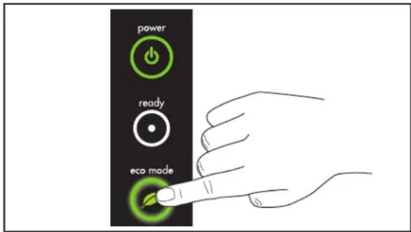
ECO Mode
This mode saves energy by minimizing the energy wasted during unit down-time.

IMPORTANT
ECO Mode is most effective in installations where the unit has a regular OFF period.
To achieve the most benefit from the energy saving ECO Mode on your ECO Boiler unit, follow these procedures:
Towards the end of the Boiler's operating period for a given day, switch the machine to ECO Mode. This will maintain water at 203°F and the unit's Tank will slowly drop to half full.
At the end of the day, the Boiler should be turned Off.
During the Off period, as there is less water in the Tank, there will be less energy lost to the surrounding environment resulting in an energy saving.
To Disable ECO Mode:
Press the ECO Mode Button again. The leaf symbol will no longer be illuminated.
MAINTENANCE
MAINTENANCE RECOMMENDATIONS
Keep the unit at peak efficiency by performing all scheduled maintenance procedures that are recommended by Vivreau. Proper maintenance will allow the best performance and a longer working life.
⚠ WARNING Before performing any maintenance or service procedure, perform all safety procedures. In particular, turn OFF the water supply, disable the electricity at the main circuit breaker and prevent access to all devices that might cause unexpected health and safety hazards if turned ON.
▲WARNING Before performing any maintenance or service that involves electrical connection or disconnection and/or exposure to electrical components, ALWAYS follow the Electrical LOCKOUT/TAGOUT Procedure. Disconnect all circuits. Failure to comply can cause property damage, injury or death.
At the end of each day or whenever necessary, be sure to clean:
- Dispensing Head/Nozzle
- Drip Tray
• The surrounding work area
Every year, have skilled, authorized personnel perform the following operations:
- General check of the unit
- Identify and replace worn parts
i IMPORTANT
Record all yearly inspections.
i IMPORTANT
Contact the factory, the factory representative or an authorized service agent to perform service and repairs.
ELECTRICAL LOCKOUT/TAGOUT PROCEDURE
▲WARNING Before performing any maintenance or service procedure that involves electrical connection or disconnection and/or exposure to electrical components, ALWAYS follow the Electrical LOCKOUT/TAGOUT Procedure. Disconnect all circuits. Failure to comply can cause property damage, injury or death.
The Electrical LOCKOUT/TAGOUT Procedure is used to protect personnel working on an electrical unit. Before performing any maintenance or service that requires exposure to electrical components, follow these steps:
In Electrical Box, place unit Circuit Breaker into OFF position.
Place a lock or other device on the Electrical Box Cover to prevent someone from placing Circuit Breaker in the ON position.
Place a tag on Electrical Box Cover to indicate that unit has been disconnected for service and power should not be restored until tag is removed by maintenance personnel.
Disconnect the unit's Power Cord from Electrical Outlet.
Place a tag on the Power Cord to indicate that the unit has been disconnected for service and power should not be restored until tag is removed by maintenance personnel.
STAINLESS STEEL CARE
Cleaning
Stainless steel contains 70-80% iron, which will rust if not properly maintained. It also contains 12-30% chromium, which forms an invisible passive, protective film that shields against corrosion. If the film remains intact, the stainless steel will remain intact. However, if the film is damaged, the stainless steel can break down and rust. To prevent stainless steel breakdown, follow these steps:
▲ CAUTION Never use any metal tools. Scrapers, files, wire brushes or scouring pads (except for stainless steel scouring pads) will mar the surface.
⚠️ CAUTION Never use steel wool, which will leave behind particles that rust.
▲ CAUTION Never use acid-based or chloride-containing cleaning solutions, which will break down the protective film.
CAUTION Never rub in a circular motion.
▲CAUTION Never leave any food products or salt on the surface. Many foods are acidic. Salt contains chloride.
For routine cleaning, use warm water, mild soap or detergent and a sponge or soft cloth.
For heavy-duty cleaning, use warm water, a degreaser and a plastic, stainless steel or Scotch-Brite pad.
Always rinse thoroughly.
Always rub gently in the direction of the steel grain.
Preserving & Restoring
Special stainless steel polishing cleaners can preserve and restore the protective film.
Preserve the life of stainless steel with a regular application of a high quality stainless steel polishing cleaner as a final step to daily cleaning.
If signs of breakdown appear, restore the stainless steel surface. First, thoroughly clean, rinse and dry the surface. Then, on a daily basis, apply a high-quality stainless steel polish according to manufacturer's instructions.
Heat Tint
Darkened areas, called heat tint, may appear on stainless steel exposed to excessive heat, which causes the protective film to thicken. It is unsightly but is not a sign of permanent damage.
To remove heat tint, follow the routine cleaning procedure. Stubborn heat tint will require heavy-duty cleaning.
To reduce heat tint, limit the exposure of equipment to excessive heat.
DAILY CLEANING
The ViTAP Dispensing System should be cleaned once a day.
Vivreau recommends using disinfectant spray or a sanitizing wipe for cleaning.
If the Dispensing Head becomes soiled with coffee, tea, milk etc. clean with hot soapy water using a non-abrasive cloth.
Clean the Drip Tray Cover and inside the Drip Tray using either disinfectant spray (non-chlorine) or hot, soapy water and non-abrasive cloth.
Keep area around the unit clean and sanitized.
ViTAP equipment in the under-counter area should be kept free of dust; the ventilation should not be obstructed restricting free air flow around the equipment.
The ViTAP Nozzle should be removed daily and cleaned with hot soapy water and a non-abrasive cloth.
After completing all cleaning tasks, dispense water for at least 10 seconds to flush through the Nozzle.
Use hot water if the unit is equipped with a Boiler.
DO NOT use any abrasive material on your ViTAP Dispensing System.
CLEANING SCHEDULE
| Cleaning Schedule | |||
| Component Task Frequency Personnel | |||
| Dispensing Head/Nozzle Cleaning & Sanitizing Daily End-User | |||
| Drip Tray Draining, Cleaning Daily End-User | |||
| CO2 Cylinder | Fill Level Weekly | End- User | |
| Replace As Needed | |||
| Chiller Condenser Grille Cleaning, Degreasing Weekly End-User | |||
| Chiller Exterior | Cleaning Weekly | End-User | |
| Water Filter | Replacement | Twice Yearly | Authorized Service Dealer |
CLEANING NOZZLE & COVER
The Dispensing Head has a removable Nozzle for ease of cleaning and sanitizing.
⚠ WARNING Wear protective gloves when handling Sanitizing Solution.
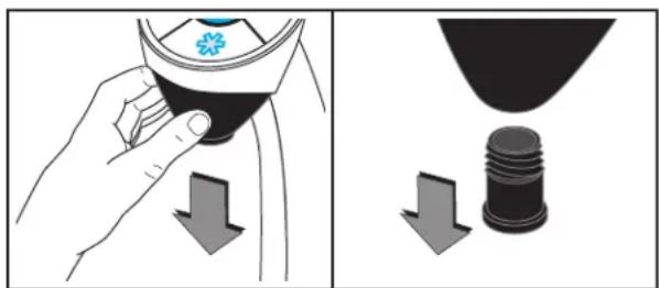
natural_image
Illustration showing a hand holding a cap with a flower symbol, and a close-up of a black object with a threaded base (no text or symbols)Cleaning Nozzle and Cover
Fill a small container with Sanitizing Solution.
Remove Cover by pulling down.
Unscrew the Nozzle.
Submerge Nozzle and cover in Sanitizing Solution.
Soak for a minimum of 4 hours.
Remove parts from Sanitizing Solution and rinse thoroughly.
Re-install Nozzle and Cover.
Wipe external surfaces of Dispensing Head, Drip
Tray and countertop with a clean cloth.
CLEANING THE DRIP TRAY
⚠ WARNING Wear protective gloves when handling Sanitizing Solution.
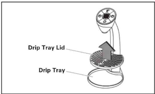
Cleaning the Drip Tray
Lift Drip Tray Lid from unit.
Wipe top and bottom of Drip Tray Lid with a clean cloth and Sanitizing Solution.
Wipe interior of Drip Tray with a clean cloth and Sanitizing Solution.
Replace Drip Tray Lid.
CLEANING THE COOLING SYSTEM CONDENSER GRILLE
The Cooling System Condenser Grille is located on the front side of the Cooler/Carbonator.

Cooling System Condenser Grille Location
▲CAUTION Condenser Grille must be kept clean and unobstructed to allow proper cooling of components. Damage to the unit will occur due to overheating!
i IMPORTANT
Never cover the Cooling Fins.
i IMPORTANT
Never place objects in front of the Cooling Fins.
The Cooling Fins should never be blocked and a minimum distance of 4" to other objects must be maintained.
Clean the Cooling Fins with a suitable brush or vacuum cleaner.
Degrease with a soft cloth sprayed with degreaser.
⚠️ CAUTION Never spray degreaser or any other liquid into the Condenser Grille.
EXTERIOR CLEANING
Wipe all surfaces with a soft cloth and a non-abrasive cleaner.
i IMPORTANT
Never use an abrasive cleaner to clean the unit.
CHANGING THE CO _2 CYLINDER
⚠ WARNING Wear protective gloves and safety glasses when changing CO₂ Cylinders.
⚠ WARNING CO 2 is a colorless, odorless gas. A danger of suffocation exists when in high concentration. Make sure there is adequate ventilation when exchanging CO 2 Cylinders.
The CO_2 Cylinder can either be located inside the cabinet with the system or outside the in a remote location.
Regardless of location, the Cylinder is fitted with a Regulator that has been preset for proper operation. The Regulator should never be adjusted by the end-user.
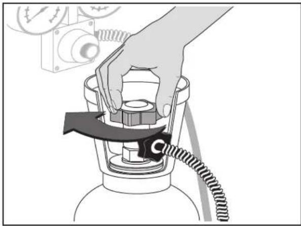
To change the CO_2 Cylinder close the Valve on top of the empty Cylinder.
natural_image
Illustration of a hand pressing down on a cylindrical device with a coiled cable, no text or symbols presentClose Empty Cylinder Valve
Release the line pressure by opening the Sparkling Water Dispenser until no gas escapes.
natural_image
Illustration of a hand interacting with a circular device with icons (no text or symbols)Dispensing Chilled Sparkling Water
Loosen the connection to the Cylinder with the wrench provided and remove the Regulator from the Cylinder.
⚠ WARNING The line is pressurized. Pressure will be released while performing this procedure. Handle carefully.

natural_image
Illustration of a hand using a tool to adjust or install a gas cylinder component (no text or symbols visible)Disconnect High-Pressure Hose
SECURE CYLINDER
Move empty Cylinder to storage area and secure safely.
Remove the plastic plug or tape from the new Cylinder outlet and discard it.

IMPORTANT
To avoid confusion, do not replace plastic plugs in the outlet of empty CO₂ Cylinders.
⚠ WARNING Wear protective gloves and safety glasses when purging Cylinder. Be sure to point the Cylinder outlet away from your body.
Purge the replacement Cylinder by quickly opening and closing the Valve on top to clear any dust or moisture from the outlet.
Connect the High-Pressure Hose or Primary Regulator. Make sure the Sealing Washer is seated correctly.
The Regulator should be hand-tightened to the new Cylinder and then tightened firmly with the wrench provided. Never over-tighten.
Open the Valve on top of the Cylinder.
Check for leaks using a solution of soapy water or a commercial equivalent.

Checking for Leaks
Refer to your local CO_2 supplier for complete handling and safety instructions.
▲CAUTION Run all hoses so they cannot be damaged by abrasion or high heat.
STANDING IDLE
Before Long Idle Periods
If the ViTAP Dispensing System will be idle for more than 3 days:
Unplug the Unit.
Close the Water Supply Valve.
Clean the following with antibacterial wipes and disinfectant spray:
- Dispensing Nozzle
- Dispensing Head
• Drip Tray - Cabinet surfaces
Hang the DO NOT USE sign on the Dispensing Head to ensure the Dispensing System will not be used while the water supply is disconnected.
Cover the Dispensing Head with plastic film.

IMPORTANT
If the Carbonator Pump Protection has switched off the Carbonator Pump, then the unit must be reset. To reset the unit, unplug the Power Cord and plug it back in.
AFTER LONG IDLE PERIODS
⚠ WARNING Danger to health from a lack of sanitization!
Bacteria and germs can form if the water dispenser has been disconnected from the power supply for longer than 72 hours.
After a longer idle period or a power failure, proceed as follows:
Remove the plastic film from the Dispensing Head.
Clean the following areas with antibacterial cloths and sanitizing spray:
- Dispensing Nozzle
- Dispensing Head
- Drip Tray
- Cabinet surfaces
Plug in the unit.
Open the Water Supply Valve to restore the water to the unit.
Place a suitable container on the Drip Tray.
Rinse the Water Dispenser by running 0.5 gallons of still water.
Rinse the Water Dispenser by running 0.5 gallons of sparkling water.
i IMPORTANT
After an idle period of four weeks or more, rinse the water dispenser by running 5.0 gallons of still water and 5.0 gallons of sparkling water.
Remove the DO NOT USE sign.
Unit is ready for normal use.
LEAK PROCEDURES
Leaks in equipment can occur even if all precautions and procedures have been followed properly.
Follow the procedures listed below in the event of a leak.
WATER
Disconnect the Water Dispenser from the power supply.
Disconnect the water supply by closing the
Water Supply Valve.
Clean up the leaked water from the area.
Indicate the ViTAP Dispensing System is out of service by hanging a DO NOT USE sign on the Dispensing Head.
Contact Vivreau Service Toll-Free at 877-999-1044.
CO_2
Disconnect the Water Dispenser from the power supply.
Close the CO_2 Cylinder Valve.
Open the windows and doors to ventilate the room thoroughly.
Indicate the ViTAP Dispensing System is out of service by hanging a DO NOT USE sign on the Dispensing Head.
Contact Vivreau Service Toll-Free at 877-999-1044.
REFRIGERANT
Disconnect the Water Dispenser from the power supply.
Disconnect the Water Supply by closing the Water Supply Valve.
⚠ WARNING Contact with refrigerant is hazardous to your health! Avoid contact!
Indicate the ViTAP Dispensing System is out of service by hanging a DO NOT USE sign on the Dispensing Head.
Contact Vivreau Service Toll-Free at 877-999-1044.
ELECTRIC SHOCK
Disconnect the Water Dispenser from the power supply.
Disconnect the water supply by closing the Water Supply Valve.
▲DANGER Risk of Electrocution! Unplug equipment or turn off supply circuit breaker immediately.
After removing the immediate danger, Contact Vivreau Service Toll-Free at 877-999-1044.
Indicate the ViTAP Dispensing System is out of service by hanging a DO NOT USE sign on the Dispensing Head.
TROUBLESHOOTING
The information provided in this section is intended to assist in the basic identification and correction of simple irregularities and malfunctions which might occur during daily operation.

IMPORTANT
Service and repairs must only be performed by properly qualified and trained service personnel.
Always switch off and unplug the equipment before servicing or repairing the unit.
BASIC TROUBLESHOOTING
NO STILL WATER
Check Water Supply Valve is open.
NO SPARKLING WATER
If only gas is coming out, check the main Water Supply or power. If nothing is coming out, check CO_2 Cylinder and change if needed.
LED DISPLAY
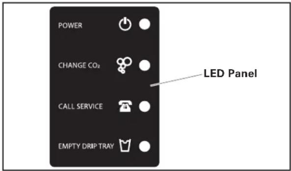
Dispensing Head System LED Display Panel
POWER: Make sure unit is plugged in.
CHANGE CO _2 : Replace CO2 Cylinder.
CALL SERVICE: Unplug unit and check still water.
If still water is not working, check Water Block and water supply. Plug in unit. If Service Light returns call Vivreau Service.
EMPTY DRIP TRAY (Not Activated on this Unit): Empty the Drip Tray waste container.
NO HOT WATER (if equipped with Boiler)
Check that the Power Cord is plugged in and the Power Switch is ON.
WARM WATER (Still and Sparkling)
Make sure Chiller/Carbonator is plugged in and operating.
Make sure the Condenser Grille is not clogged or blocked.
If these Troubleshooting procedures do not resolve the issue, contact Vivreau Service Toll-Free at 877-999-1044.
NOTES
NOTES
NOTES

Intertek


natural_image
Abstract water splash illustration with bubbles and splashes (no text or symbols)



Freshly-drawn Traditionally Served Environmentally Friendly Specially Branded
EUROPE

VIVREAU UK (head office)
+44 (0)845 674 9655
email: info@vivrcau.com

VTVREAU Russia
Tel: +74 9 5620 4720
Email: info@vivrcau.ru

VIVREAL Ireland
+44 (0)845 674 9655
cmail: info@vivrcau.ic

VIVREAU Switzerland
+41 (0)22 344 86 70
natural_image
Abstract water splash illustration with blue water droplets and splashes against white background (no text or symbols)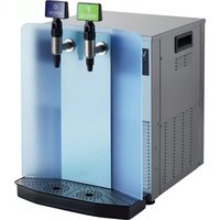

- i IMPORTANT
- TABLE OF CONTENTS
- SAFETY PRECAUTIONS
- IMPORTANT
- GENERAL INFORMATION
- INFORMATION FOR THE READER
- PURPOSE OF THE MANUAL
- DANGER
- WARNING
- CAUTION
- TECHNICAL SPECIFICATIONS
- GENERAL DESCRIPTION
- PRE-INSTALLATION REQUIREMENTS
- PRE-INSTALLATION
- WATER SUPPLY
- ELECTRICAL OUTLET
- Model ViTAP-2
- Model ViTAP-2H
- Model ViTAP-2HD
- CO _2
- DRIP TRAY AND DISPENSING HEAD CUTOUTS
- DRIP TRAY DRAIN
- LOCATION OF SERVICES
- SHIPPING DAMAGE/MISSING PARTS
- LOCATION
- VENTILATION
- DISPENSING HEAD
- OPERATING INSTRUCTIONS
- BEFORE USE
- LED DISPLAY PANEL
- DISPENSING
- Chilled Still Water
- Chilled Sparkling Water
- Hot Water (if supplied)
- AFTER DAILY USE
- FOR UNITS WITH OPTIONAL HOT WATER BOILER
- Operating Boiler for the First Time:
- ECO MODE
- To Enable ECO Mode:
- To Disable ECO Mode:
- MAINTENANCE
- MAINTENANCE RECOMMENDATIONS
- ELECTRICAL LOCKOUT/TAGOUT PROCEDURE
- STAINLESS STEEL CARE
- Cleaning
- Preserving & Restoring
- Heat Tint
- DAILY CLEANING
- CLEANING SCHEDULE
- CLEANING NOZZLE & COVER
- CLEANING THE DRIP TRAY
- CLEANING THE COOLING SYSTEM CONDENSER GRILLE
- EXTERIOR CLEANING
- CHANGING THE CO _2 CYLINDER
- SECURE CYLINDER
- STANDING IDLE
- Before Long Idle Periods
- AFTER LONG IDLE PERIODS
- ⚠ WARNING Danger to health from a lack of sanitization!
- LEAK PROCEDURES
- WATER
- CO_2
- REFRIGERANT
- ⚠ WARNING Contact with refrigerant is hazardous to your health! Avoid contact!
- ELECTRIC SHOCK
- ▲DANGER Risk of Electrocution! Unplug equipment or turn off supply circuit breaker immediately.
- TROUBLESHOOTING
- BASIC TROUBLESHOOTING
- NO STILL WATER
- NO SPARKLING WATER
- NO HOT WATER (if equipped with Boiler)
- WARM WATER (Still and Sparkling)
- NOTES
- EUROPE
Brand : Vivreau
Model : Vi TAP-2H
Category : Ice Maker