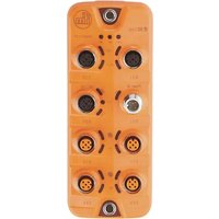
AL1300 - Industrial interface IFM - Free user manual and instructions
Find the device manual for free AL1300 IFM in PDF.


| Product Type | Photoelectric Sensor |
| Model | AL1300 |
| Brand | IFM |
| Dimensions (H x W x D) | Approx. 60 x 30 x 20 mm |
| Weight | Approx. 50 g |
| Power Supply Voltage | 10–30 V DC |
| Current Consumption | Max. 50 mA |
| Output Type | PNP/NPN, Normally Open/Closed |
| Detection Range | 0–2 m (depending on reflector) |
| Light Source | Red laser (650 nm) |
| Protection Class | IP65 |
| Ambient Temperature | -10 to +60 °C |
| Housing Material | Stainless steel / Plastic |
| Connection | M12 plug, 4-pin |
| Indication | LED for output status |
| Mounting | Screw mounting with brackets |
| Cleaning | Wipe with dry, soft cloth |
| Safety | Do not stare into laser beam; class 1 laser |
| Spare Parts | Reflectors, mounting brackets, connectors |
| Manual Languages | English, German, French |
Frequently Asked Questions - AL1300 IFM
User questions about AL1300 IFM
0 question about this device. Answer the ones you know or ask your own.
Ask a new question about this device
Download the instructions for your Industrial interface in PDF format for free! Find your manual AL1300 - IFM and take your electronic device back in hand. On this page are published all the documents necessary for the use of your device. AL1300 by IFM.
USER MANUAL AL1300 IFM
Operating instructions
IO-Link master with PROFINET interface
DataLine
4 ports
IP 65 / IP 66 / IP 67 /
AL1300
Firmware: 3.1.x
English
Inhaltsverzeichnis
1 Preliminary note 5
1.1 Legal and copyright information....5
1.2 Purpose of the document....5
1.3 Explanation of Symbols 5
1.4 Change history....6
2 Safety instructions 7
2.1 General 7
2.2 Required background knowledge ....7
2.3 Safety symbols on the device 7
2.4 IT security....8
3 Intended use 9
4 Function 10
4.1 Communication, parameter setting, evaluation ....11
4.1.1 IO-Link....11
4.1.2 PROFINET 11
4.1.3 Internet of Things (IoT)....11
4.1.4 Security mode 11
4.1.5 Parameter setting 11
4.1.6 Visual indication 12
4.2 Digital inputs....12
4.3 IO-Link supply 12
5 Mounting 13
5.1 Mount the device....13
6 Electrical connection
14
6.1 Notes....14
6.2 Connecting the PROFINET ports....15
6.3 Connecting the IoT port 15
6.4 IO-Link ports....16
6.4.1 Connecting IO-Link devices for Class A operation....16
6.4.2 Connecting IO-Link devices for Class B operation....17
6.5 Connecting the device 18
7 Operating and display elements
19
7.1 Overview....19
7.2 LED indicators....20
7.2.1 Status LEDs 20
7.2.2 Ethernet ports....20
7.2.3 IoT port....21
7.2.4 Voltage supply....21
7.2.5 IO-Link Ports (Class A)....21
8 Set-up 22
9 Configuration 23
9.1 LR DEVICE 24
9.1.1 Remarks....25
9.1.2 IoT: Configure IP settings....26
9.1.3 IoT: Configure security mode 26
9.1.4 IoT: Configuring access rights....27
9.1.5 IoT: Configure the interface to LR AGENT or LR SMARTOBSERVER 29
9.1.6 Fieldbus: Configure IP settings....29
9.1.7 IO-Link ports: Activate data transfer to LR AGENT or LR SMARTOBSERVER 30
9.1.8 IO-Link ports: Configure operating mode....31
9.1.9 IO-Link ports: Set the device validation and data storage 32
9.1.10 Info: Show device information 33
9.1.11 Firmware: Reset device to factory settings....33
9.1.12 Firmware: Reboot the device....33
9.1.13 Configure IO-Link devices....34
9.2 ifm IoT Core 35
9.2.1 Programmers' notes 36
9.2.2 First steps....40
9.2.3 General functions 40
9.2.4 IoT: Configuring access rights....44
9.2.5 IoT: Configuring IP settings 44
9.2.6 IoT: Configuring the LR AGENT or LR SMARTOBSERVER interface 45
9.2.7 IoT: Configuring security mode....45
9.2.8 Fieldbus: Configuring IP settings....48
9.2.9 IO-Link ports: Setting the operating mode of pin 4 (US)....48
9.2.10 IO-Link ports: Configuring device validation and data storage 49
9.2.11 IO-Link ports: Configuring data transfer to LR AGENT or LR SMARTOBSERVER....51
9.2.12 IO-Link ports: Reading / writing process data....51
9.2.13 IO-Link ports: Indicating port events....54
9.2.14 IO-Link devices: Accessing parameters 54
9.2.15 IO-Link devices: Reading an writing device information....56
9.2.16 IO-Link devices: Indicating IO-Link events 56
9.2.17 Gateway: Resetting, rebooting and localising the device 56
9.2.18 Gateway: Reading device information....57
9.2.19 Gateway: Reading status and diagnostic information....57
9.2.20 Gateway: Updating the firmware 58
9.2.21 Gateway: Setting the application tag 59
9.2.22 Subscribing to notifications....60
9.2.23 Using Web Socket....64
9.2.24 MQTT support....66
9.2.25 Using the IoT-Core Visualizer....70
9.3 PROFINET....77
9.3.1 Install GSD Files....78
9.3.2 Integrate the IO-Link master in the project 78
9.3.3 Configure the IO-Link master 79
9.3.4 Configure IO-Link ports 80
9.3.5 Configure IO-Link devices 81
9.3.6 Read and write cyclic process data....81
9.3.7 Read I&M datasets....82
9.3.8 Detect diagnostics and alarms 82
10 Operation 83
10.1 Using web-based management....83
11 Maintenance, repair and disposal 84
11.1 Cleaning process....84
11.2 Updating the firmware....84
11.3 Replacing IO-Link device....84
12 Factory settings 85
13 Accessories 86
14 Appendix 87
14.1 Technical data....88
14.1.1 Application....88
14.1.2 Electrical data....88
14.1.3 Inputs / outputs....88
14.1.4 Inputs 89
14.1.5 Outputs....89
14.1.6 Interfaces....89
14.1.7 Operating conditions 90
14.1.8 Approvals / tests....90
14.1.9 Mechanical data 90
14.1.10 Electrical connection 91
14.2 PROFINET....92
14.2.1 Parameter data....92
14.2.2 Cyclic data....95
14.2.3 Acyclic data 97
14.3 ifm IoT Core 99
14.3.1 Overview: IoT profile 100
14.3.2 Overview: IoT types....107
14.3.3 Overview: IoT services 108
15 Index 122
1 Preliminary note
Content
Legal and copyright information....5
Purpose of the document 5
Explanation of Symbols....5
Change history....6
33203
1.1 Legal and copyright information
33117
© All rights reserved by ifm electronic gmbh. No part of this manual may be reproduced and used without the consent of ifm electronic gmbh.
All product names, pictures, companies or other brands used on our pages are the property of the respective rights owners:
• AS-i is the property of the AS-International Association, (→ www.as-interface.net)
• CAN is the property of the CiA (CAN in Automation e.V.), Germany (→ www.can-cia.org)
• CODESYS™ is the property of the CODESYS GmbH, Germany (→ www.codesys.com)
- DeviceNet ^™ is the property of the ODVA ^™ (Open DeviceNet Vendor Association), USA (→ www.odva.org)
- EtherNet/IP ^ is the property of the ODVA ^TM
- EtherCAT ^® is a registered trade mark and patented technology, licensed by Beckhoff Automation GmbH, Germany
- IO-Link ^ is the property of the PROFIBUS Nutzerorganisation e.V., Germany ( www.io-link.com)
- ISOBUS is the property of the AEF – Agricultural Industry Electronics Foundation e.V., Deutschland (→ www.aef-online.org)
- Microsoft ^ is the property of the Microsoft Corporation, USA (→ www.microsoft.com)
- Modbus® is the property of the Schneider Electric SE, France (→ www.schneider-electric.com)
- PROFIBUS ^® is the property of the PROFIBUS Nutzerorganisation e.V., Germany (→ www.profibus.com)
- PROFINET ^ is the property of the PROFIBUS Nutzerorganisation e.V., Germany
- Windows ^ is the property of the Microsoft Corporation, USA
1.2 Purpose of the document
34227
This document is only for device types "IO-Link master - PROFINET gateway (DataLine) 4 port IP 65 / IP 66 / IP 67/" (art. no.: AL1300).
It is part of the device and contains information about the correct handling of the product.
▶ Read this document before using the device.
▶ Keep this document during the service life of the device.
1.3 Explanation of Symbols
34171

WARNING
Warning of serious personal injury.
Death or serious irreversible injuries may result.

CAUTION
Warning of personally injury.
Slight reversible injuries may result.
NOTICE
Warning of damage to property

Important note
Non-compliance can result in malfunction or interference

Information
Supplementary note
▶ ...
Request for action
...
Reaction, result
→ ...
"see"
abc
Cross-reference
123
Decimal number
0x123
Hexadecimal number
0b010
Binary number
[...]
Designation of pushbuttons, buttons or indications
1.4 Change history
42782
| Version | Topic | Date |
| 00 | New creation of the document | 04 / 2019 |
| 01 | Corrected: Technical data - current rating per output | 09 / 2019 |
| 02 | Added: New IoT core functionsAdded: IoT Core VisualizerCorrection: Description SENS PWR and AUX PWRCorrection: Description of the IoT Core Service getsubscriptioninfo | 10 / 2020 |
| 03 | Deleted: ifm IoT Core – DNS support | 10 / 2021 |
2 Safety instructions
Content
General....7
Required background knowledge....7
Safety symbols on the device....7
IT security 8
28333
2.1 General
58525
- The device described is a subcomponent for integration into a system. The manufacturer is responsible for the safety of the system. The system manufacturer undertakes to perform a risk assessment and to create documentation in accordance with legal and normative requirements to be provided to the operator and user of the system. This documentation must contain all necessary information and safety instructions for the operator, the user and, if applicable, for any service personnel authorised by the manufacturer of the system.
- Read this document before setting up the product and keep it during the entire service life.
- The product must be suitable for the corresponding applications and environmental conditions without any restrictions.
- Only use the product for its intended purpose (→ Intended use (→ p. 9)).
- If the operating instructions or the technical data are not adhered to, personal injury and/or damage to property may occur.
- The manufacturer assumes no liability or warranty for any consequences caused by tampering with the product or incorrect use by the operator.
- Installation, electrical connection, set-up, programming, configuration, operation and maintenance of the product must be carried out by personnel qualified and authorised for the respective activity.
- Protect units and cables against damage.
2.2 Required background knowledge
34185
This document is intended for specialists. Specialists are people who, based on their relevant training and experience, are capable of identifying risks and avoiding potential hazards that may be caused during operation or maintenance of the product.
The document contains information about the correct handling of the product.
2.3 Safety symbols on the device
34199

General warning
Observe instructions in chapter "Electrical connection" (→ Electrical connection (→ p. 14))!
2.4 IT security
54678
NOTICE!
If the device is operated in an unprotected network environment.
Unauthorised read or write access to data is possible.
Unauthorised manipulation of the device function is possible.
▶ Check and restrict access options to the device:
- Restrict access to authorised persons.
- Do not connect the device to open networks or the internet.
If access from the internet is inevitable:
▶ choose a safe method to connect with the device (e. g. VPN).
▶ Use encrypted data transmission (e. g. https / TLS).
3 Intended use
58283
The device may only be used for the following purposes:
- as IO-Link master for configuration, administration and operation of IO-Link devices
- as gateway between IO-Link devices and AS-i network
The device is designed for use without a control cabinet in plant construction.
▶ Only use the device within the limits of the technical data ( Technical data ( p. 88)).
4 Function
Content
Communication, parameter setting, evaluation....11
Digital inputs....12
IO-Link supply....12
33836
4.1 Communication, parameter setting, evaluation
Content
IO-Link 11
PROFINET 11
Internet of Things (IoT)....11
Security mode....11
Parameter setting....11
Visual indication....12
33860
4.1.1 IO-Link
34084
The device offers the following IO-Link functions:
• IO-Link master (IO-Link revision 1.0 and 1.1)
- 4 IO-Link ports for connection of IO-Link devices
- Provision of process data of the connected IO-Link devices for LR SMARTOBSERVER monitoring software (→ www.ifm.com)
4.1.2 PROFINET
52555
The device offers the following PROFINET functions:
• Profinet RT Device (Class B)
- 2 port switch for access to the PROFINET interface; integrated switch is RT and IRT conform according to PROFINET V2.3
- Gateway for transmission of the process and parameter data between the connected IO-Link devices and the higher-level PROFINET controller
• Supported protocols: SNMP, LLDP, MRP, DCP, RTA, RTC Class 1 (not synchronized)
• PROFINET features: FSU, I&M0 - 4 read/write
• Device description: GSDML file
4.1.3 Internet of Things (IoT)
54679
The device offers the following IoT functions:
- Gateway for the transmission of process, parameter and monitoring data between IO-Linkmaster / IO-Link devices and the IT network level
- REST-API to access process and parameter data
• Supported protocols: TCP/IP JSON, MQTT
4.1.4 Security mode
54697
The IoT interface offers the following optional security functions:
- Secure data transfer via encrypted connection (Secure Layer Transport - TLS)
- Access protection via authentication
4.1.5 Parameter setting
34210
The device provides the following configuration options:
- Parameter setting of the IO-Link master of the AL1300 with LR DEVICE parameter setting software, PROFINET projection software or ifm IoT-Core services.
- Parameter setting of the connected IO-Link devices (sensors, actuators) with LR DEVICE parameter setting software, PROFINET projection software or ifm IoT-Core services
• Storage of parameter sets of the connected IO-Link devices for automatic recovery (data storage)
4.1.6 Visual indication
34192
The device has the following visual indicators:
- Status and error indication of the gateway, of the PROFINET connection and of the system
• Status display of the voltage supply - Status and activity display of the Ethernet connection
- Status, error and short circuit/overload indication of the IO-Link ports
4.2 Digital inputs
33817
The device has 4 additional digital inputs (type 2 according to EN 61131-2).
The digital inputs are on pin 2 of the ports X01...X04.
All inputs refer to the potential of the device supply (pin 3).
4.3 IO-Link supply
34077
The device has 4 supplies for IO-Link devices.
The IO-Link ports X01...X04 are ports class A.
Every supply provides short circuit monitoring.
The device ensures fire protection for the connected IO-Link devices by providing a power-restricted circuit at the IO-Link ports (according to IEC61010-1 and Class 2 according to UL1310).
5 Mounting
Content
Mount the device ....13
34058
5.1 Mount the device
34059

▶ Disconnect the system from power before installation.
▶ For installation choose a flat mounting surface.
▶ Please observe the maximum tightening torque.
▶ Fix the unit to the mounting surface using 2 M5 mounting screws and washers.
- Tightening torque: 1.8 Nm
▶ Ground the unit via the two mounting screws of the upper mounting lugs.
6 Electrical connection
Content
Notes 14
Connecting the PROFINET ports....15
Connecting the IoT port....15
IO-Link ports....16
Connecting the device....18
33805
6.1 Notes
51957

A qualified electrician must connect the unit.
The national and international for regulations setting up electrical equipment must be complied with.
The unit is only suitable for operation using SELV/PELV voltages.
▶ Please note the information concerning IO-Link wiring!
This unit contains components that may be damaged or destroyed by electrostatic discharge (ESD).
▶ Please observe the required precautions against electrostatic discharge!
The M12 connection parts in the device comply with the ingress resistance requirements of the standard EN 61076-2-101. To adhere to the protection rating, only cables certified to this standard must be used. The system creators undertake to ensure ingress resistance for cables which they cut to length themselves.
- Carry out the fitting according to the indications of the cable manufacturer. A maximum of 0.8 Nm is permitted.
▶ During installation, place the M12 connector vertically so that the coupling nut will not damage the thread.
▶ Depending on the mounting conditions, cables must be provided with a strain relief to avoid unacceptable loads on the mounting points and M12 connections.
▶ Make sure that the M12 connection parts are correctly seated and mounted correctly. The specified protection rating can not be guaranteed if this is not observed.
For UL applications:
To connect the IO-Link master and the IO-Link devices, only use UL-certified cables of the CYJV or PVVA category with a minimum temperature of 80 °C (75 °C in case of maximum ambient temperature of 40 °C).
Wiring: → Technical data (→ p. 88)
By means of basic insulation according to EN61010-1, the circuits are separated from each other and from device surfaces that could be touched (secondary circuit with 30 V DC maximum, supplied from mains circuit up to 300 V overvoltage category II).
By means of basic insulation according to EN61010-1, the communication interfaces are separated from each other and from device surfaces that could be touched (secondary circuit with 30 V DC maximum, supplied from mains circuit up to 300 V overvoltage category II). They are designed for network environment 0 according to IEC TR62102.
6.2 Connecting the PROFINET ports
33671

natural_image
Top-down schematic of a mobile phone casing showing front panel, top panel, and internal compartments (no text or symbols)▶ Connect the device via the M12 socket X21 and/or X22 to the PROFINET network
(e.g. PROFINET PLC, additional PROFINET device)
▶ To connect the devices, use M12 connectors with protection rating IP 65 / IP 66 / IP 67 / or higher (→ Accessories (→ p. 86)).
▶ Cover the unused sockets with M12 protective caps (art no. E73004).
6.3 Connecting the IoT port
34044
natural_image
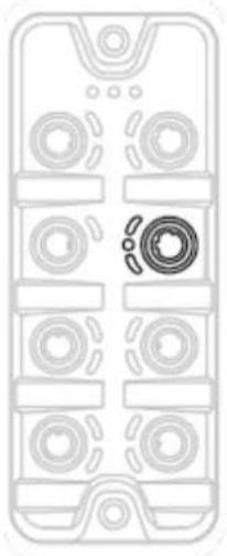
Top-down schematic of a mobile phone casing with circular components and a central circular component (no text or symbols)▶ Connect the device via the M12 socket X23 to the IT network (e.g. laptop/PC with LR DEVICE parameter setting software, laptop/PC with LR SMARTOBSERVER monitoring software, laptop/PC with software capable of processing http requests).
▶ To connect the devices, use M12 connectors with protection rating IP 65 / IP 66 / IP 67 / or higher (→ Accessories (→ p. 86)).
▶ Cover the unused sockets with M12 protective caps (art no. E73004)
6.4 IO-Link ports
51958
The IO-Link ports of the AL1300 meet the requirements of the IO-Link specifications 1.0 to 1.1.2.
▶ Please note the information concerning IO-Link wiring!
▶ Cover unused sockets with M12 protective caps (art. no.: E73004).
6.4.1 Connecting IO-Link devices for Class A operation
51959
Wiring information:
- The connected IO-Link devices must be supplied exclusively via the IO-Link master.
- The additional digital inputs IO-Link ports X01...X04 (pin 2) have a type 2 behaviour according to the standard EN61131-2. The connected electronics must be electrically suited for this.

natural_image
Top-down schematic of a mobile phone casing showing front panel, rear panels, and internal components (no text or symbols)▶ Connect the connectors of the IO-Link devices with the M12 sockets of the IO-Link ports X01...X04.
■ Maximum cable length per IO-Link port: 20 m
▶ To connect the devices, use M12 connectors with protection rating IP 65 / IP 66 / IP 67 / or higher (→ Accessories (→ p. 86)).
6.4.2 Connecting IO-Link devices for Class B operation
51960
Notes on wiring:
- For Class B operation, the IO-Link device must be supplied with an additional auxiliary voltage UA using a Y connection cable.

WARNING
Non-compliance with the electrical separation of the circuits
Risk of fire!
▶ Ensure that the external supply UA is galvanically separated from the circuit of the IO-Link Master by assuring basic insulation (according to IEC 61010-1, secondary circuit with 30 V DC maximum, supplied from mains circuit up to 300 V of overvoltage category II).
▶ Ensure that the IO-Link devices and the connection technology support the galvanic separation.

In case of operation as port class B, the additional digital input of the IO-Link port (pin 2) is not available!
natural_image
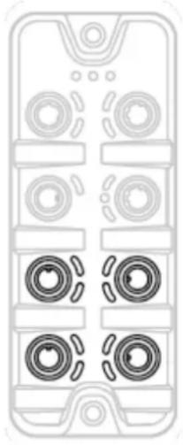
Top-down schematic of a mobile phone casing showing four circular components and one central button (no text or labels)▶ Connect the connectors of the IO-Link devices via a Y connection cable with the M12 sockets of the IO-Link ports X01...X04.
▶ Connect the Y cable to 24 V DC (20...30 V SELV/PELV)
▶ To connect the devices, use M12 connectors with protection rating IP 65 / IP 66 / IP 67 / or higher (→ Accessories (→ p. 86))!
6.5 Connecting the device
33882

natural_image
Top-down schematic of a mobile phone casing with multiple circular components and a central button (no text or symbols)▶ Disconnect power.
Connect the IO-Link Master via M12 socket X31 to 24 V DC (20...30 V SELV/PELV; according to EN61010-1, secondary circuit with maximum 30 V DC supplied by mains circuit up to 300 V of overvoltage category II).
- Maximum cable length: 25 m
▶ To connect the device, use M12 connectors with protection rating IP 65 / IP 66 / IP 67 / or higher (→ Accessories (→ p. 86)).

When using cable length greater than 25 m keep in mind the voltage drop as well as the required minimum voltage supply of 20 V!
7 Operating and display elements
Content
Overview....19
LED indicators 20
34063
7.1 Overview

34356
① RDY, BF and SF status LEDs
$$ \rightarrow \text { Status LEDs } (\rightarrow p. 2 0) $$
② LNK and ACT status LEDs of the PROFINET
$$ \text { interfaces 1 (X21) and 2 (X22) } $$
$$ \rightarrow \text { Ethernet ports } (\rightarrow p. \underline {{2 0}}) $$
③ LNK, ACT status-LEDs and IoT LED of the IoT
$$ \text { interface } (X 2 3) $$
$$ \rightarrow \text { IoT port } (\rightarrow p. \underline {{2 1}}) $$
④ IOL and DI status-LEDs of the IO-Link port (X01...X04)
$$ \rightarrow \text { IO - Link Ports (Class A) } (\rightarrow p. 2 1) $$
⑤ PWR status LED of the voltage supply (X31)
$$ \rightarrow \text { Voltage supply } (\rightarrow p. 2 1) $$
7.2 LED indicators
The device only has the following LED indicators:
34047
7.2.1 Status LEDs
The RDY LED shows the status of the gateway.
The BF LED (Bus Failure) shows the status of the PROFINET connection.
The SF LED (System Failure) shows the status of the system.
| Status LED | Description | ||
| RDY | green | on | Status: OK |
| flashes 5 Hz | Status: Error | ||
| flashes (200 ms on, 800 ms off) | Status: Firmware update is running | ||
| off | Status: Gateway not running or gateway booting | ||
| BF | red | on | Bus error |
| flashes 1 Hz | No connection to the PROFINET controller | ||
| off | error-free | ||
| SF | red | on | • Error in gateway• At least 1 IO-Link device sends warning / alarm (temperature, over/under current, over/under voltage, shortcut) |
| off | error-free | ||
7.2.2 Ethernet ports
34348
Each Ethernet port has 2 LEDs (LNK and ACT). The LEDs indicate the status of the Ethernet connection.
| Status LED | Description | ||
| LNK | green | on | Ethernet connection established |
| off | No Ethernet connection | ||
| ACT | yellow | flashes | Data is transmitted via the Ethernet interface. |
| off | No data transmission | ||
7.2.3 IoT port
34043
The IoT port has the 3 LNK, ACT and IoT LEDs. The LEDs indicate the status of the Ethernet connection and the device identification.
| Status LED | Description | ||
| LNK | green | on | Ethernet connection established |
| off | No Ethernet connection | ||
| ACT | yellow | flashes | Data is transmitted via the Ethernet interface. |
| off | No data transmission | ||
| IoT | green | flashes | Device identification active |
7.2.4 Voltage supply
34191
The interface for voltage supply (X31) has the LED that is marked as US. The LED indicates the status of the voltage supply.
| Status LED | Description | ||
| US | green | on | The supply voltage Us is applied. |
| off | No supply voltage is applied or the applied supply voltage is too low. | ||
7.2.5 IO-Link Ports (Class A)
34074
Each IO-Link Port Class A has 2 LEDs labelled IOL and DI. The LEDs indicate the status of the IO-Link port.
| Status LED | Description | ||
| IOL | yellow | Off | Port configured as DI/DO: pin 4 (C/Q) = OFF |
| on | Port configured as DI/DO: pin 4 (C/Q) =ON | ||
| green | flashing 1 Hz | Port configured asIO-Link: no IO-Link device found | |
| Flashing with 2 Hz | Port configured asIO-Link: Status PREOPERATE | ||
| on | Port configured asIO-Link: Status OPERATE | ||
| red | Flashing with 2 Hz | Port configuration error or short circuit / overload on US | |
| on | Transmission Error | ||
| DI | yellow | Off | Digital input: pin 2 = OFF |
| on | Digital input: pin 2 = ON | ||
8 Set-up
52357
When the supply voltage is switched on, the AL1300 starts with the factory settings. The display elements signal the current operating mode ( Operating and display elements ( p. 19)).
To enable parameter setting of the AL1300, the IoT interface and / or the fieldbus interface must be configured according to the network environment.
▶ Configure IoT interface (LR DEVICE: → IoT: Configure IP settings (→ p. 26) or → IoT: Configuring IP settings (→ p. 44)).
▶ Configure fieldbus interface (LR DEVICE: → Fieldbus: Configure IP settings (→ p. 29) or IoT: → Feldbus-Schnittstelle konfigurieren).
IoT / fieldbus interface has valid IP settings.
User can set the parameters of the AL1300.
Further steps:
- Optional: Update firmware of AL1300 (→ Updating the firmware (→ p. 84)).
- Set the parameters of the AL1300 (→ Configuration (→ p. 23)).
9 Configuration
Content
LR DEVICE....24
ifm IoT Core 35
PROFINET 77
33858
9.1 LR DEVICE
Content
Remarks 25
IoT: Configure IP settings....26
IoT: Configure security mode 26
IoT: Configuring access rights....27
IoT: Configure the interface to LR AGENT or LR SMARTOBSERVER 29
Fieldbus: Configure IP settings 29
IO-Link ports: Activate data transfer to LR AGENT or LR SMARTOBSERVER 30
IO-Link ports: Configure operating mode ....31
IO-Link ports: Set the device validation and data storage....32
Info: Show device information 33
Firmware: Reset device to factory settings 33
Firmware: Reboot the device....33
Configure IO-Link devices....34
33692
On delivery, the AL1300 is configured with the factory settings ( Factory settings ( p. 85)).
Required software: LR DEVICE (1.5.0.x or higher) (art.-no.: QA0011/QA0012)
9.1.1 Remarks
Content
Offline parameter setting....25
VPN connection....25
34180
Offline parameter setting
34060
The AL1300 supports the offline parameter setting. In this context, the user creates and stores a configuration for the IO-Link master and the connected IO-Link devices without being connected to the AL1300 (OFFLINE mode). The configuration created in this way can be stored as a file (*.lrp) and loaded to the AL1300 and activated at a later date.

Further information about offline parameter setting: → Operating instructions LR DEVICE
VPN connection
34382

An active VPN connection blocks the access of the parameter setting software LR DEVICE to the PROFINET interface of the AL1300.
▶ Deactivate the VPN connection in order to be able to access the AL1300 with the LR DEVICE.
9.1.2 IoT: Configure IP settings
34049
For access to the IO-Link master via the IT infrastructure the user has to set the IP settings of the IoT port.

To configure the IP settings with DHCP, a DHCP server has to be active in the IT network. If no DHCP server can be reached in the IT network, an IP address is automatically assigned to the IoT port with the Zeroconfig protocol (address range: → Factory settings (→ p. 85)).
To configure the IP settings of the IoT interface:
▶ Select [IoT] menu.
The menu page shows the current settings.
▶ Set the following parameters as required:
| Name | Description | Possible values | |
| [DHCP] | Activate/deactivate the DHCP client of the device | [Static IP] | IP settings were set by the user |
| [DHCP] | IP settings are set by a DHCP server in the network. | ||
| [IP address]* | IP address of the IoT port | Factory setting: 169.254.X.X | |
| [Subnet mask]* | Subnet mask of the Ethernet network | Factory setting: 255.255.0.0 | |
| [Default gateway IP address]* | IP address of the network gateway | Factory setting: 0.0.0.0 | |
| [MAC address] | MAC address of the IoT port | The value is firmly set. | |
* ... can only be edited if parameter [DHCP] = [Static IP]
▶ Save changed values on the device.
9.1.3 IoT: Configure security mode
54680
The IoT interface of the IO-Link offers a security mode. It enables secure data transmission via transport encryption and restriction of the access to IO-Link masters and IO-Link devices via user authentication.
To configure the security mode:
▶ Select [IoT] menu.
The menu page shows the current settings.
▶ Set the following parameters as required:
| Name | Description | Possible values | |
| [Security mode HTTPS] | Set the security mode | [Disabled] | Security mode disabled |
| [Enabled] | Security mode enabled | ||
| [Security password] | PasswordNote: The set password is not displayed. | ||
▶ Save changed values on the device.

The security mode only protects the access to the device via the IoT interface. The user name "administrator" cannot be changed.

The security mode can be enabled without setting the password. During the attempt to write to the device, LR DEVICE requires to enter and confirm the password.
After entering the password, the user has unrestricted access to IO-Link masters and connected IO-Link devices. The password will only be requested again if the current LR DEVICE session is over (e.g. after restarting the LR DEVICE).
To change the set password:
▶ Sign in with a valid password.
▶ Enter the new password in the field [Security password].
▶ Write changes to the device.
The new password is set.
9.1.4 IoT: Configuring access rights
34046
The access rights define which instance may read and / or write the parameter data, process data and event/diagnostic messages.
In order to configure the access rights to the IO-Link master:
▶ Select [IoT] menu.
The menu page shows the current settings.
▶ Set the following parameters as required:
| Name | Description | Possible values | |
| [Access Rights] | The access rights to the parameter data, process data and the event/diagnostic messages of the IO-Link master as well as the connected IO-Link devices | [PROFINET + IoT]* | • PROFINET and IoT Core have read and write access rights to parameters and process data• PROFINET and IoT Core have read access rights to events/alarms |
| [PROFINET + IoT (read-only)] | • PROFINET has read and write access rights to parameters and process data• PROFINET has read access rights to events/alarms• IoT Core only has read access rights to parameters, process data and events/alarms | ||
| [IoT only] | • IoT Core has read and write access rights to parameters and process data• IoT has read access rights to events/alarms• PROFINET has no access rights | ||
* ... Factory setting
▶ Save changed values on the device.

If in LR DEVICE and PROFINET projection software the parameter [Access Rights] is = [PROFINET + IoT], the parameter values set in the PROFINET projection software will always apply.
If the parameter [Access Rights] in LR DEVICE is = [IoT only], set the parameter [Access Rights] = [Keep settings] in the PROFINET projection software.
If the parameter [Access Rigts] in LR DEVICE is = [
Changes of the parameter [Access Rights] will only be effective after restarting the IO-Link master ( Firmware: Reboot the device ( p. 33)).
9.1.5 IoT: Configure the interface to LR AGENT or LR SMARTOBSERVER
34048
To enable transfer of process data from the IO-Link master to LR AGENT or LR SMARTOBSERVER, the interface has to be configured accordingly.
▶ Select [IoT] menu.
The menu page shows the current settings.
▶ Set the following parameters as required:
| Name | Description | Possible values | |
| [IP address LR Agent or SMARTOBSERVER] | IP address of LR AGENT or LR SMARTOBSERVER | Factory setting: 255.255.255.255 | |
| [Port LR Agent or SMARTOBSERVER] | Port number that is used to send process data to LR AGENT or LR SMARTOBSERVER | 0...65535 | Factory setting:: 35100 |
| [Interval LR Agent or SMARTOBSERVER] | Cycle time for the transfer of the process data to LR AGENT or LR SMARTOBSERVER (value in milliseconds) | [Off] | no transfer |
| 500...2147483647 | 500 ms...2147483647 ms | ||
| [Application Tag] | Source identifier of the IO-Link master in the structure of LR AGENT or LR SMARTOBSERVER (String32) | Factory setting: AL1300 | |

After changing the parameter [Port LR Agent or SMARTOBSERVER] or [Application Tag], it may take 120 seconds before the device establishes a new TCP connection.
To prevent the delay:
▶ Reboot the device after changing the the parameter.
▶ Save changed values on the device.
9.1.6 Fieldbus: Configure IP settings
34527
The PROFINET interface (ports X21/X22) has to be configured in order to access the IO-Link master via the PROFINET.
To set the IP properties of the fieldbus interface:
▶ Select [Fieldbus] menu.
The menu page shows the current settings.
▶ Set the following parameters as required:
| Parameter | Description | Possible values |
| [IP address] | IP address of the PROFINET interface | Factory setting: 0.0.0.0 |
| [Subnet mask] | Subnet mask of the PROFINET network | Factory setting: 0.0.0.0 |
| [Default gateway IP address] | IP address of the gateway | Factory setting: 0.0.0.0 |
| [Hostname] | Name of the device in the PROFINET network | e.g. al1xxx |
| [MAC address] | MAC address of the device | The value is firmly set. |
▶ Save changed values on the device.
9.1.7 IO-Link ports: Activate data transfer to LR AGENT or LR SMARTOBSERVER
33690
The user can decide separately for each IO-Link port whether the process data of the connected IO-Link devices should be transferred to LR AGENT or LR SMARTOBSERVER.

To transfer process data the interface to the LR AGENT or LR SMARTOBSERVER has to be correctly configured ( IoT: Configure the interface to LR AGENT or LR SMARTOBSERVER ( p. 29)).
To activate / deactivate data transfer:
▶ Select [Port x] menu (x = 1...4).
The menu page shows the current settings.
▶ Set the following parameters as required:
| Name | Description | Possible values | |
| [Transmission to LR Agent or SMARTOBSERVER] | Transfer of process data of the connected IO-Link device to LR AGENT oder LR SMARTOBSERVER | [Disabled] | Transfer process data |
| [Enabled] | Don't transfer process data | ||
▶ Save changed values on the device.
9.1.8 IO-Link ports: Configure operating mode
33694
The IO-Link ports X01...X04 of the device support the following operating modes:
- Disabled: no data transfer at pin 4 (C/Q) of the IO-Link port
- Digital input (DI): binary input signal at pin 4 (C/Q) of the IO-Link port
- Digital output (DO): binary output signal at pin 4 (C/Q) of the IO-Link port
- IO-Link: IO-Link data transfer via pin 4 (C/Q) of the IO-Link port
The user can set the operating mode separately for each IO-Link port.
To set the operating mode of an IO-Link port:
▶ Select [Port x] menu (x = 1...4).
The menu page shows the current settings.
▶ Set the following parameters as required:
| Name | Description | Possible values | |
| [Mode Pin4 US] | Operating mode of pin 4 of the IO-Link port | [Disabled] | Port deactivated |
| [DI] | Operation as digital input | ||
| [DO] | Operation as digital output | ||
| [IO-Link] | Operation as IO-Link interface | ||
| [Cycle time actual]** | Current cycle time of the data transfer between IO-Link master and IO-Link device on the port (value in microseconds) | Parameter can only be read | |
| [Cycle time preset]* | Cycle time of the data transfer between the IO-Link master and the IO-Link device at the port (value in microseconds) | 0 | The device automatically sets the fastest possible cycle time. |
| 1 ... 132800 | 1 microsecond ... 132800 microseconds | ||
| [Bitrate]** | Current transmission rate of the data transfer between the IO-Link master and the IO-Link device on the port | Parameter can only be read | |
* ... Parameter only available if [Mode] = [IO-Link]
** ... Parameter only visible if the IO-Link device is connected to the IO-Link port.
▶ Save changed values on the device.
9.1.9 IO-Link ports: Set the device validation and data storage
33697
The user can choose how the IO-Link ports are to behave with regard to the device validation and the storage / recovery of parameter data of the connected IO-Link device.
The following options are available:
| Option | Validation of the IO-Link device | Storage of the parameter values | Recovery of the parameter values |
| [No check and clear] | no | no | no |
| [Type compatible V1.0 device] | yes, test the compatibility with IO-Link standard V1.0 | no | no |
| [Type compatible V1.1 device] | yes, test the compatibility with IO-Link standard V1.1 | no | no |
| [Type compatible V1.1 device with Backup + Restore] | yes, test the compatibility with IO-Link standard V1.1 and identity of design (vendor ID and device ID) | yes, automatic storage of the parameter values; changes of the current parameter values will be stored | yes, recovery of the parameter values when connecting an identical IO-Link device with factory settings |
| [Type compatible V1.1 device with Restore] | yes, test the compatibility with IO-Link standard V1.1 and identity of design (vendor ID and device ID) | no, there is no automatic storage changes of the current parameter values will not be stored | yes, recovery of the parameter values when connecting an identical IO-Link device with factory settings |

The options only apply if the IO-Link port is in the operating mode "IO-Link".
For options [Type compatible V1.1 device with Backup + Restore] and [Type compatible V1.1 device with Restore]: If the vendor ID and device ID are changed in the online mode, the data memory will be deleted and a new backup of the parameter values of the connected IO-Link device will be created in the IO-Link master.
To configure the device validation and the data storage:
▶ select [Port x] menu (x = 1...4).
The menu page shows the current settings.
▶ Set the following parameters as required:
| Name | Description | Possible values | |
| [Validation / Data Storage] | Supported IO-Link standard and behaviour of the IO-Link master when connecting a new IO-Link device at port x (x = 1...4) | [No check and clear] | |
| [Type compatible V1.0 device] | |||
| [Type compatible V1.1 device] | |||
| [Type compatible V1.1 device with Backup + Restore] | |||
| [Type compatible V1.1 device with Restore] | |||
| [Vendor ID] | ID of the manufacturer that is to be validated | 0...65535 | Factory setting: 0# ifm electronic: 310 |
| [Device ID] | ID of the IO-Link device that is to be validated | 0...16777215 | Factory setting: 0 |
▶ Save changed values on the device.
9.1.10 Info: Show device information
34065
To read the general information of the ifm IO-Link master:
▶ Select [Info] menu.
The menu page shows the current settings.
| Name | Description | Possible values |
| [Product code] | Article number of the IO-Link master | AL1300 |
| [Device family] | Device family of the IO-Link master | IO-Link master |
| [Vendor] | Vendor | ifm electronic gmbh |
| [SW-Revision] | Firmware of the IO-Link master | |
| [HW revision] | Hardware version of the IO-Link master | |
| [Bootloader revision] | Bootloader version of the IO-Link master | |
| [Serial number] | Serial number |
9.1.11 Firmware: Reset device to factory settings
33838
When the IO-Link master is reset, all parameters are set to the factory settings:
To reset the device to factory settings:
▶ Select [Firmware] menu.
The menu page shows the current settings.
▶ Click on [Factory Reset] to reset the device.
LR DEVICE sets the device to the factory settings.
9.1.12 Firmware: Reboot the device
33832
When rebooting the device, all settings are kept.
To restart the AL1300:
▶ Select [Firmware] menu.
The menu page shows the current settings.
▶ Click on [Reboot] to reboot the device.
LR DEVICE reboots the ifm IO-Link master.
9.1.13 Configure IO-Link devices
33856
To configure the IO-Link devices connected to the device with the LR DEVICE parameter setting software:
Requirements:
IO-Link master is correctly installed and connected to the LR DEVICE parameter setting software.
The IO-Link device is connected correctly with the AL1300.
Operating mode of the IO-Link port is "IO-Link" ( IO-Link ports: Configure operating mode ( p. 31)).
IoT has write access rights to the IO-Link master ( IoT: Configuring access rights ( p. 27)).
1 Select IO-Link master
▶ Start LR DEVICE.
▶ Update IODD file library OR:
Import IODD file of the IO-Link device manually.
▶ Scan network for devices.
LR DEVICE detects IO-Link master.
2 Add IO-Link device
▶ Under [ONLINE]: Click on the required IO-Link master.
LR DEVICE automatically detects the IO-Link devices connected to the IO-Link master (e.g. ifm sensor KG5065).
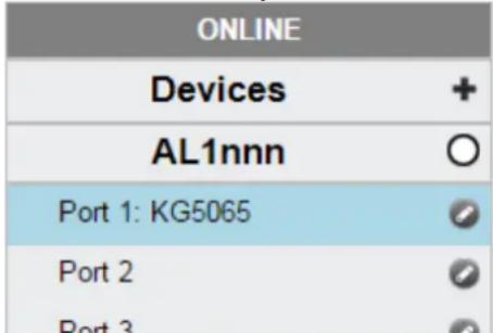
3 Configure IO-Link device
▶ Mouse click on the port to which the IO-Link device is connected.
LR DEVICE reads and shows the current parameter values of the IO-Link device.
▶ Configure IO-Link device.

Information about the available parameters of the IO-Link device: → IO Device Description (IODD) des IO-Link Devices
▶ Save the changed configuration on the IO-Link device.
9.2 ifm IoT Core
Content
Programmers' notes ....36
First steps 40
General functions 40
IoT: Configuring access rights....44
IoT: Configuring IP settings....44
IoT: Configuring the LR AGENT or LR SMARTOBSERVER interface 45
IoT: Configuring security mode 45
Fieldbus: Configuring IP settings....48
IO-Link ports: Setting the operating mode of pin 4 (US) 48
IO-Link ports: Configuring device validation and data storage....49
IO-Link ports: Configuring data transfer to LR AGENT or LR SMARTOBSERVER ....51
IO-Link ports: Reading / writing process data ....51
IO-Link ports: Indicating port events....54
IO-Link devices: Accessing parameters....54
IO-Link devices: Reading an writing device information 56
IO-Link devices: Indicating IO-Link events 56
Gateway: Resetting, rebooting and localising the device....56
Gateway: Reading device information....57
Gateway: Reading status and diagnostic information....57
Gateway: Updating the firmware 58
Gateway: Setting the application tag 59
Subscribing to notifications....60
Using Web Socket....64
MQTT support 66
Using the IoT-Core Visualizer 70
52244

General notes on the ifm IoT Core: → Programmers' notes (→ p. 36)
9.2.1 Programmers' notes
Content
IoT Core: General information....36
Access the ifm IoT Core 37
IoT Core: Diagnostic codes....39
34229
IoT Core: General information
52256
The DataLine device family has an IoT Core. The IoT Core allows the user to address the AL1300 from IT networks via a REST API and to integrate it into Internet-of-Things applications.
A device description is stored on the AL1300. This device description is a structured, machine-readable data object in JSON format. All current values of parameters, process data, diagnostic data and device information are mapped in this data object. These data values can be read and changed by means of services.
Access the ifm IoT Core
52257
The user can access the ifm IoT Core via HTTP requests. The following request methods are available.
GET request
33804
Using the GET method the user has read access to a data point.
The syntax of the request to the IoT Core is:
http://ip/datapoint/service
| Parameter | Description |
| ip | IP address of the IoT interface |
| data_point | Data point which is to be accessed |
| service | Service |
The syntax of the return of the IoT Core is:
{
"cid": id,
"data": {"value": resp_data},
"code": diag_code
}
| Parameter | Description |
| id | Correlation ID for the assignment of request and return |
| resp_data | Value of the data point; depending on the data type of the data point |
| diag_code | Diagnostic code (→ IoT Core: Diagnostic codes (→ p. 39)) |
Example: GET request
54033
Request (via browser):
http://192.168.0.250/devicetag/applicationtag/getdata
Response:
{
    "cid": -1,
    "data": {"value":"AL1300"},
    "code": 200
}
POST request
54700
Using a POST request the user has read and write access to a data point.
The syntax of the request to the IoT Core is:
{
    "code": "code_id",
    "cid": id,
    "adr": "data_point/service",
    "data": {req_data},
    "auth": {"user": "usr_id", "passwd": "password"}
}
| Field | Parameter | Description | |
| code | code_id | Service class | |
| request | Request | ||
| transaction | Transaction | ||
| event | Event | ||
| cid | id | Correlation ID for the assignment of request and response; ID freely assignable by the user | |
| adr | data_point | Data point of the element tree which is to be accessed | |
| service | Service to be performed (→Overview: IoT services (→p. 108)) | ||
| data* | req_data | Data to be transferred to the IoT Core (e.g. new values); syntax depending on the service | |
| auth** | usr_id | user name (base64 coded); default value: administrator | |
| password | password (base64 coded) | ||
* = optional; only required for services, that submit data to the IoT core (e. g. setdata)
** = optional; only required, if security mode is activated
The syntax of the return of the IoT Core is:
{
    "cid": id,
    "data": {resp_data},
    "code": diag_code
}
| Field | Parameter | Description |
| cid | id | Correlation ID for the assignment of request and response (see request) |
| data* | resp_data | Value of the data point; syntax depending on the service |
| code | diag_code | Diagnostic code ( IoT Core: Diagnostic codes ( p. 39)) |
* = optional; only required for services, that receive data from the IoT core (e.g. getdata)
Example: POST request
54035
Request:
{
    "code": "request",
    "cid": 4711,
    "adr": "devicetag/applicationtag/getdata"
}
Response:
{
"cid":4711,
"data":{"value":"AL1300"},
"code":200
}
IoT Core: Diagnostic codes
54688
| Code | Text | Description |
| 200 | OK | Request successfully processed |
| 230 | OK but needs reboot | Request successfully processed; IO-Link master must be restarted |
| 231 | OK but block request not finished | Request successfully processed; blockwise request, but not yet finished |
| 232 | Data has been accepted, but internally modified | New values have been accepted, but were adjusted by the IO-Link master (Master cycle time) |
| 233 | IP settings (of IoT-Port) have been updated.Application needs to reload device. Wait at least 1 second before reloading device. | IP settings have been successfully changed, IO-Link master will be reloaded; wait for at least 1 second |
| 400 | Bad request | Invalid request |
| 401 | Unauthorized | Non authorised request |
| 403 | Forbidden | Forbidden request |
| 500 | Internal Server Error | Internal fault |
| 503 | Service Unavailable | The service is not available (e. g. IO-Link port in wrong operating mode; no IO-Link device at IO-Link port) |
| 530 | The requested data is invalid | Invalid process data |
| 531 | IO-Link error | Error in IO-Link Master / device |
| 532 | PLC connected Error | Error while setting data, because IO-Link master is still connected to fieldbus PLC |
9.2.2 First steps
52245
To read the device description of the AL1300:
▶ Send the following POST request to the AL1300:
{"code":"request","cid):-1,"adr":"gettree"}
AL1300 returns the device description as structured JSON object.
▶ Identify all substructures and the data points contained therein in the tree structure of the JSON object.
▶ Identify the applicable services for the access to substructures and the data points contained therein.
9.2.3 General functions
61148
The AL1300 has the type device ( Overview: IoT types ( p. 107)).
The following services can be used on the root element of the type device:
| Service | Description |
| ../gettree | Provide the complete tree or subtree of the device description (JSON) |
| ../getidentity | Reading device information |
| ../getdatamulti | Reading several parameter values sequentially |
| ../getelementinfo | Reading detailed information of an element |
| ../getsubscriberlist | Print a list of all active notification subscriptions |
| ../querytree | Search device description for specific elements |
Depending on the read and write access rights, the following services can be applied to elements of type data:
| Service | Description |
| ../getdata | Reading the value of the element |
| ../setdata | Write the value of the element |
Example: Reading properties of an element
59782
Task: Determine the data type and value range of the accessrights parameter.
Solution: Read the properties of the element iotsetup/accessrights of the getelementinfo service. The fields type (data type) and valuation (range of values) contain the required information.
- Request:
{
  "code": "request",
  "cid": 4711,
  "adr": "getelementinfo",
  "data": {"adr": "iotsetup/accessrights"}
}
- Response:
{
  "cid": 4711,
  "data": {
  "identifier": "accessrights",
"type":"data",
"uid":null,
"profiles":["parameter"],
"format":{
"type":"enum",
"namepace":"json",
"encoding":"integer",
"valuation":{
"valuelist":{
"0":"Fieldbus + IoT",
"1":"Fieldbus + IoT (read-only)",
"3":"IoT only"}}}, "code":200
}
The accessrights parameter has the data type ENUM with the valid values "Fieldbus + IoT", "Fieldbus + IoT (read only)" and "IoT only".
Example: output subtree
61149
Task: Output all direct sub-elements of the node firmware.
Solution: Use the service gettree to output the required subtree (root node: firmware, sub-levels to be shown: 1)
- Request:
{
  "code": "request",
  "cid": 4711,
  "adr": "gettree",
  "data": {
  "adr": "firmware",
  "level": 1}
}

- Response:
{
  "cid": 4711,
  "data": {
  "identifier": "firmware",
  "type": "structure",
  "profiles": [
    "software", "software/uploadablesoftware"],
    "subs": [
    {
    "identifier": "version", "type": "data", "profiles": ["parameter"],
    "format": {"type": "string", "namespace": "json", "encoding": "UTF-8"}],
    {
    "identifier": "type", "type": "data",
    "format": {"type": "string", "namespace": "json", "encoding": "UTF-8"}],
    {
    "identifier": "install", "type": "service"},
    {
    "identifier": "factoryreset", "type": "service"},
    {
    "identifier": "signal", "type": "service"},
    {
    "identifier": "container", "type": "data",
    "format": {"type": "binary", "namespace": "json", "encoding": "base64"}],
{
    "identifier":"reboot","type":"service"}
},
"code":200
}
Example: Read several parameter values of the IO-Link master simultaneously
33840
Task: The following current values are to be read by the IO-Link master: temperature, serial number
Solution: Read the current parameter values using the getdatamulti service (data point temperature: /processdatamaster/temperature; data point serial number: /deviceinfo/serialnumber)
- Request:
{
  "code": "request",
  "cid": 4711,
  "adr": "/getdatamulti",
  "data": {"datatosend": ["/processdatamaster/temperature", "/deviceinfo/serialnumber"]
}
}
- Response:
{
  "cid": 4711,
  "data": {"processdatamaster/temperature": {"code": 200, "data": 44},
  "deviceinfo/serialnumber": {"code": 200, "data": "000174210147"}},
  "code": 200
}
Example: Browsing device description
61150
Task: List all elements with the designation "status" and the profile "runcontrol".
Solution: Use the service querytree to browse the device description with the parameters "status" (name) and "runcorntrol" (profile)
- Request:
{
    "cid":4711,
    "adr":"querytree",
    "code":"request",
    "data":{
    "profile":"runcontrol",
    "name":"status"
    }
}
- Response:
{
    "cid":4711,
    "data":{
    "adrList":[
    "device/connections/mqttConnection/status",
    "device/connections/mqttConnection/mqttCmdChannel/status"]},
    "code":200
}
Setting the storage duration
61153
The IoT Core offers the possibility to set the storage duration of data and notifications. The Services Service: setdata ( p. 118) and Service: subscribe ( p. 120) therefore have the parameter "duration".
Example: Subscribing to notifications
61154
Task: The current values of the following parameters are to be sent regularly to a network server with IP address 192.168.0.4:
- Product name of the IO-Link Devices an IO-Link port X02
• Cyclic input data of the IO-Link Devices an IO-Link port X02 - Operating temperature of the IO-Link master.
The subscription is only to be active until the next restart of the IO-Link master.
Solution: Subscribe to the required data using the subscribe service.
- Request:
{
    "code": "request",
    "cid": 4711,
    "adr": "/timer[1]/counter/datachanged/subscribe",
    "data": {
    "callback": "http://192.168.0.4:80/temp",
    "datatosend": [
    "/iolinkmaster/port[2]/iolinkdevice/productname",
    "/iolinkmaster/port[2]/iolinkdevice/pdin",
    "/processdatamaster/temperature"],
    "duration": "uptime"
    }
}
• Response:
{
    "cid": 4711,
    "code": 200
}
9.2.4 IoT: Configuring access rights
59785
Substructure: iotsetup
Available data points:
| Name | Description | Access |
| ../accessrights | Access rights to the IO-Link master | rw |
rw ... read and write

If in IoT and PROFINET projection software the parameter [Access Rights] is = [PROFINET + IoT], the parameter values set in the PROFINET projection software will always apply.
If in IoT the parameter [Access Rights] is = [IoT only], set the parameter [Access Rights] = [Keep settings] in the PROFINET projection software.
If in LR DEVICE the parameter [Access Rigts] is = [EtherCAT + IoT (read-only)], write access to the device configuration via LR DEVICE and IoT core services is blocked. To enable write access again, set the parameter to [EtherCAT + IoT] via fieldbus configuration software.
Changes of the parameter [Access Rights] will only be effective after restarting the IO-Link master ( Firmware: Reboot the device ( p. 33)).
9.2.5 IoT: Configuring IP settings
61155
Substructure: iotsetup
Available data points:
| Name | Description | Access |
| ../network/dhcp | Configuration of the IP settings of the IoT port | rw |
| ../network/ipaddress | IP address of the IoT port | rw |
| ../network/subnetmask | Subnet mask of the network segment | rw |
| ../network/ipdefaultgateway | IP address of the network gateway | rw |
rw ... read and write
Applicable services:
| Name | Description |
| ../network/setblock | Write all values of the substructure blockwise |

Change the IP parameters in the substructure network only blockwise with the setblock service!
9.2.6 IoT: Configuring the LR AGENT or LR SMARTOBSERVER interface
59786
Substructure: iotsetup
Available data points:
| Name | Description | Access |
| ../smobip | IP address of the LR SMARTOBSERVER | rw |
| ../smobport | Port number of the LR SMARTOBSERVER | rw |
| ../smobinterval | Cycle time for data transmission to LR SMARTOBSERVER (value in milliseconds) | rw |
rw ... read and write
9.2.7 IoT: Configuring security mode
54683
The access to the IoT interface of the IO-Link master can be protected with a security mode:
Substructure: iotsetup
Available data points:
| Name | Description | Access |
| ../security/securitymode | active security mode | rw |
| ../security/password | Password for authentication (Base64 coded) | w |
rw ... read and write
w ... write only

Valid character set for the Base64 coding / decoding of the password: UTF-8
Online tool for coding / decoding: → www.base64encode.org
Note: Security mode
54684
The security mode enables restricting access to the IO-Link master and the connected IO-Link devices from the IT network. In the activated security mode, the following restrictions apply:
- Access only with authentication (password-protected user account)
- Access only via secure https connection (Transport Layer Security - TLS)

The security mode only protects the access to the device via the IoT interface.
The standard value for users is: administrator
The set password cannot be read with getdata.
The current status of the security function can be read with the getidentity service ( Servicet: getidentity ( p. 111)).
For the authentication, the user must additionally provide the POST requests with a valid user name and password in the field "auth". The user name and the password will be shown as Base64-coded character strings (→ Example: Request with authentication (→ p. 46)).
The following requests can be done if the security mode is enabled, also without authentication:
• /getidentity
• /deviceinfo/vendor/getdata
• /deviceinfo/productcode/getdata
Example: Activate security mode
54701
Task: Activate the security mode of the IO-Link interface of the IO-Link master. Set the password "password" (Base64 coded: cGFzc3dvcmQ=)
Solution: The activation sonsists of 2 steps:
1 Activate security mode
Use service setdata with datapoint iotsetup/security/securitymode to activate the security mode.
- Request:
{
    "code": "request",
    "cid": -1,
    "adr": "/iotsetup/security/securitymode/setdata",
    "data": {"newvalue":"1"}
}
- Response:
{
    "cid": -1,
    "code": 200
}
2 Set required password
Use service setdata with data point iotsetup/security/password to set the required password.
- Request:
{
    "code": "request",
    "cid": -1,
    "adr": "/iotsetup/security/password/setdata",
    "data": {"newvalue":"cGFzc3dvcmQ Heroin Whiter = Heroin Whiter Heroin Whiter Heroin Whiter Heroin Whiter Heroin Whiter Heroin Whiter Heroin Whiter Heroin Whiter Heroin Whiter Heroin Whiter Heroin Whiter Heroin Whiter Heroin Whiter Heroin Whiter Heroin Whiter Heroin Whiter Heroin Whiter Heroin Whiter Heroin Whiter Heroin Whiter Heroin Whiter Heroin Whiter Heroin Whiter Heroin Whiter Heroin Whiter Heroin Wh器
}
- Response:
{
    "cid": -1,
    "code": 200
}
Example: Request with authentication
54685
Task: The temperature of the IO-Link master is to be read. The security function is enabled (current password: password).
Solution: Read the data point processdatamaster/temperature with the getdata service. The request must be sent using https. The user name and the password are transferred as a Base64-coded character string ("administrator" = "YWRtaW5pc3RyYXRvcg==", "password" = "cGFzc3dvcmQ=")
- Request:
{
    "code": "request",
    "cid": -1,
    "adr": "processdatamaster/temperature/getdata",
    "auth": {"user": "YWRtaW5pc3RyYXRvcg==", "passwd": "cGFzc3dvcmQ="}
}
- Response:
{
    "cid": -1,
    "data": {"value": 37},
    "code": 200
}
Example: reset password
54686
Task: The existing password is to be reset.
Solution: To reset a password, disable the security mode. To disable it, enter the user name and the password (the fields "user" and "passwd").
- Request:
{
    "code": "request",
    "cid": -1,
    "adr": "iotsetup/security/securitymode/setdata",
    "data": {"newvalue": 0},
    "auth": {"user": "YWRtaW5pc3RyYXRvcg==", "passwd": "SW9UNGlmbQ=="}
}
- Response:
{
    "cid": -1,
    "code": 200
}
9.2.8 Fieldbus: Configuring IP settings
59808
Substructure: fieldbussetup
Available data points:
| Name | Description | Access |
| ../hostname | Name of the IO-Link master in the fieldbus project | rw |
| ../fieldbusfirmware | Firmware version of the IO-Link master | r |
| ../network/macaddress | MAC address of the fieldbus port | r |
| ../network/ipaddress | IP address of the fieldbus port | rw* |
| ../network/subnetmask | Subnet mask of the network segment | rw* |
| ../network/ipdefaultgateway | IP address of the network gateway | rw* |
| ../connectionstatus | Status of the connection to the PROFINET network | r |
r ... read only
rw ... read and write
* ... only changeable, if the PROFINET controller is not in RUNNING state
9.2.9 IO-Link ports: Setting the operating mode of pin 4 (US)
59793
Substructure: iolinkmaster/port[n] (n = 1...4).
Available data points:
| Name | Description | Access |
| ../mode | Operating mode of the IO-Link port | rw* |
| ../mastercycletime_preset | Cycle time of the data transfer at the IO-Link port (value in ms) | rw* |
| ../mastercycletime_actual | Current cycle time of the data transfer at the IO-Link port (value in ms) | r |
| ../comspeed | Data transfer rate of the IO-Link port | r |
r ... read only
rw ... read and write
* ... only changeable, if the
9.2.10 IO-Link ports: Configuring device validation and data storage
59792
Substructure: iolinkmaster/port[n] (n = 1...4).
Available data points:
| Name | Description | Access |
| ../validation_datastorage_mode | Response of the IO-Link port when a new IO-Link device is connected | rw* |
| ../validation_vendorid | IO-Link ID of the manufacturer that is to be validated | rw* |
| ../validation_deviceid | IO-Link ID of the device that is to be validated | rw* |
| ../datastorage | Structure for port data storage | rw |
| ../datastorage/maxsize | Maximum size of the data storage content (in bytes) | r |
| ../datastorage/chunksize | Size of a data segment (in bytes) | r |
| ../datastorage/size | Size of the data storage content (in bytes) | r |
r ... read only
rw ... read and write
* ... can only be changed if the PROFINET PLC is not in RUNNING state
Applicable services:
| Service | Description |
| ../validation_useconnecteddevice | Validate the IO-Link device connected to the IO-Link port* |
| ../datastorage/getblobdata | Reading the content of the data storage area |
| ../datastorage/stream_set | Transfer an individual data segment* |
| ../datastorage/start_stream_set | Start sequential transmission of several data segments* |
* ... can only be changed if the PROFINET PLC is not in the RUNNING state
Example: Clone the Data Storage of an IO-Link port
52344
Task: Save the Data Storage of IO-Link port X02 of IO-Link master 1 and restore the data at IO-Link master 2.
Solution: The cloning process consists of 2 steps. In the first step, the Data Storage of the IO-Link port of IO-Link master 1 is saved. In the second step, the saved data is restored at the Data Storage of port IO-Link port of IO-Link master 2.
Save Data Storage:
1 Preparations
▶ Read size of segments of Data Storage (h = number of bytes):
{"code":"request", "cid": -1, "adr":"/iolinkmaster/port[2]/datastorage/chunksize/getdata"}
Example: h = 256
▶ Read total size of Data Storage area (g = number of bytes):
{"code": "request", "cid": -1, "adr": "/iolinkmaster/port[2]/datastorage/size/getdata"}
Example: g = 550
▶ Calculate the number of reading steps n: n = first integer value to which the following applies: g < n*h
Example: n=3, because 550<3*256
2 Read Data Storage of IO-Link port
Read Data Storage segment by segment ("pos" is the byte offset, at which the reading process with length "length" starts).
{"code": "request", "cid": -1, "adr": "/iolinkmaster/port[2]/datastorage/getblobdata", "data": {"pos": 0, "length": h}} {"code": "request", "cid": -1, "adr": "/iolinkmaster/port[2]/datastorage/getblobdata", "data": {"pos": h, "length": h}} {"code": "request", "cid": -1, "adr": "/iolinkmaster/port[2]/datastorage/getblobdata", "data": {"pos": 2*h, "length": h}}
...
{"code": "request", "cid": -1, "adr": "/iolinkmaster/port[2]/datastorage/getblobdata", "data": {"pos": n*h, "length": h}} Example:
1st read request: pos = 0, length = 256
2nd read resquest: pos = 256, length = 256
3rd read request: pos = 512, length = 256
Each segment value will be returned as BASE64 coded string.
▶ Join segments.
Restore Data Storage:
1 Preparations
▶ Determine the size of the saved Data Storage value (n = number of bytes).
Example: n = 550
▶ Read size of segments (s = number of bytes):
{"code":"request", "cid": -1, "adr":"/iolinkmaster/port[1]/datastorage/chunksize/getdata"}
Example: s = 256
2 Transfer Data Storage strings
▶ Start transfer of Data Storage string ("size" = size of Data Storage string):
{"code":"request", "cid": -1, "adr":"/iolinkmaster/port[1]/datastorage/start_stream_set", "data": {"size": n}}
Example: size = 550
▶ Transfer Data Storage string segment by segment ("value" = string value of length s):
{"code": "request", "cid": -1, "adr": "/iolinkmaster/port[1]/datastorage/stream_set", "data": {"value":
"aWZtfgIAAABBTDF4NXhfY25faXRfdDluMi43Nw..."}
9.2.11 IO-Link ports: Configuring data transfer to LR AGENT or LR SMARTOBSERVER
59795
Substructure: iolinkmaster/port[n] (n = 1...4).
Available data points:
| Name | Description | Access |
| ../senddatatosmob | Process data to LR AGENT or LR SMARTOBSERVER | rw |
rw ... read and write
9.2.12 IO-Link ports: Reading / writing process data
61156
Substructure: iolinkmaster/port[n] (n = 1...4)
Available data points:
| Name | Description | Access |
| ../pin2in | Value of the digital input on pin 2 of the IO-Link port | r |
| ../iolinkdevice/pdin | Value of the IO-Link input on pin 4 of the IO-Link port | r |
| ../iolinkdevice/pdout | Value of the IO-Link output on pin 4 of the IO-Link port | rw* |
r ... read only
rw ... read and write
*... can only be changed if the fieldbus PLC is not in RUNNING state
Example: Read IO-Link process data (operating mode "IO-Link")
33842
Task: Read the current measured value of the ifm temperature sensor TN2531 at IO-Link port X02
Solution: Read the data point for the process input data with the getdata service.
- Request:
{
  "code": "request",
  "cid": 4711,
  "adr": "/iolinkmaster/port[2]/iolinkdevice/pdin/getdata"
}
- Response:
{
  "cid": 4711,
  "data": {"value": "03C9"},
  "code": 200
}
The return value is given in hexadecimal format. Besides the temperature value the return value comprises additional information ( IO Device Description (IODD) of the sensor). The temperature value is shown in bits 2 to 15.
0x03C9 = 0b1111001001
Temperature value: 0b11110010 = 242
Therefore: The current temperature value is 24.2 °C.
Example: Writing IO-Link value (operating mode "IO-Link")
59804
Task: Switch on the buzzer of DV2500 at IO-Link Port X2. The DV2500 operates in On/Off mode.
Solution: The IODD of the DV2500 shows the structure of the IO-Link process value ( e.g. LED activity). The buzzer will be switched using bit 40 of the process value (OFF = 0, ON = 1).
To switch the buzzer:
- Read the current process value ( Example: Read IO-Link process data (operating mode "IO-Link") ( p. 51)).
- Set bit 40 of the read value to 1.
- Write the process value to the IO-Link device.
Example:
Read process value:
0x0000 0000 004D = 0b0000 0000 0000 0000 0000 0000 0000 0000 0000 0100 1101
New process value:
0b0000 0001 0000 0000 0000 0000 0000 0000 0000 0000 0100 1101 = 0x0100 0000 004D
- Request:
{
  "code": "request",
  "cid": 10,
  "adr": "iolinkmaster/port[2]/iolinkdevice/pdout/setdata",
  "data": {"newvalue":"01000000004D"}
}
- Response:
{
  "cid": 10,
  "code": 200
}
Example: Writing digital output (operating mode "DO")
59803
Task: Set the output value of the IO-Link devices at IO-Link Port X1 to "ON". The operating mode of the IO-Link port is "Digital Output (DO)".
Solution: Write the value 1 to data point pdout. The value has to be written as hexadecimal value with a length of 1 byte (OFF = "00", ON = "01").
- Request:
{
  "code": "request",
  "cid": 10,
  "adr": "iolinkmaster/port[1]/iolinkdevice/pdout/setdata",
  "data": {"newvalue":"01"}
}
- Response:
{
  "cid": 10,
  "code": 200
}
Example: Reading digital input (operating mode "DI")
59802
Task: Read the current input value of the IO-Link device at IO-Link port X5. The operating mode of the IO-Link port is "Digital Input (DI)".
Solution: Read the value of data point pdin. The value will be returned as hexadecimal value with a length of 1 byte (OFF = "00", ON = "01").
- Request:
{
    "code": "request",
    "cid": 10,
    "adr": "iolinkmaster/port[5]/iolinkdevice/pdin/getdata"
}
- Response:
{
    "cid": 10,
    "data": {"value": "00"},
    "code": 200
}
9.2.13 IO-Link ports: Indicating port events
59796
Substructure: iolinkmaster/port[n] (n = 1...4).
Available data points:
| Name | Description | Access |
| ../portevent | Indication of the following events at IO-Link port n: · plugging IO-Link device · pulling IO-Link device · changing operating mode of IO-Link port | r |
r ... read only

Subscribing events: → Subscribing to notifications (→ p. 60)
9.2.14 IO-Link devices: Accessing parameters
59800
The ifm IoT Core supports the configuration of the connected IO-Link devices. A parameter is accessed via IO-Link index and subindex ( IO Device Description (IODD) of the device).
Substructure: iolinkmaster/port[n]/iolinkdevice (n = 1...4)
Applicable services:
| Service | Description |
| ../iolreadacyclic | Read a parameter of an IO-Link device (acyclic) |
| ../iolwriteacyclic | Write a parameter of an IO-Link device (acyclic) |
Example: Read the parameter value of an IO-Link device
33847
Task: Read the serial number of the ifm temperature sensor TN2531 at IO-Link port X02
Solution: Read the serial number with the iolreadacyclic service from the IO-Link device (index: 21, subindex: 0)
- Request:
{
    "code": "request",
    "cid": 4711,
    "adr": "/iolinkmaster/port[2]/iolinkdevice/iolreadacyclic",
    "data": {"index": 21, "subindex": 0}
}

• Return:
{
    "cid": 4711,
    "data": {"value": "4730323134323830373130"},
    "code": 200
}
The returned value is given in hexadecimal format. The conversion of the HEX value in a STRING value is: G0214280710
Example: Change the parameter value of an IO-Link device
33844
Task: Set the output configuration OUT1 of the ifm temperature sensor TN2531 at IO-Link port X02 to the value "Hnc / hysteresis function, normally closed".
Solution: Change the parameter [ou1] of the sensor to the value 4 using the iolwriteacyclicdata service. The parameter can be accessed via IO-Link index 580, subindex 0 ( IO-Link description of the sensor).
- Request:
{
    "code": "request",
    "cid": 4711,
    "adr": "/iolinkmaster/port[2]/iolinkdevice/iolwriteacyclic",
    "data": {"index": 580, "subindex": 0, "value": "34"}
}
The value has to be given in hexadecimal format. The conversion of the STRING value in a HEX value is: 34.
- Response:
{
"cid":4711,
"code":200
}
9.2.15 IO-Link devices: Reading an writing device information
59797
Substructure: iolinkmaster/port[n]/iolinkdevice (n = 1...4)
Available data points:
| Name | Description | Access |
| ../status | Status of the connected IO-Link device | r |
| ../vendorid | IO-Link ID of the vendor | r |
| ../deviceid | IO-Link ID of the IO-Link device | r |
| ../productname | Product name of the IO-Link device | r |
| ../serial | Serial number of the IO-Link device | r |
| ../applicationspecifictag | Device-specific identification (application tag) | rw |
r ... read only
rw ... read and write
9.2.16 IO-Link devices: Indicating IO-Link events
59798
Substructure: iolinkmaster/port[n]/iolinkdevice (n = 1...4).
Available data points:
| Name | Description | Access |
| ../iolinkevent | Indication of IO-Link events | r |
r ... read only

Subscribing events: → Subscribing to notifications (→ p. 60)
9.2.17 Gateway: Resetting, rebooting and localising the device
59790
Substructure: firmware
Applicable services:
| Name | Description |
| ../factoryreset | Reset IO-Link master to factory settings |
| ../reboot | Reboot IO-Link master |
| ../signal | Trigger the flashing of the status LED |
9.2.18 Gateway: Reading device information
52254
Substructure: deviceinfo
Available data points:
| Name | Description | Access |
| ../productcode | Article number | r |
| ../vendor | Manufacturer | r |
| ../devicefamily | Device family | r |
| ../hwrevision | Hardware revision | r |
| ../serialnumber | Serial number | r |
| ../revision | Firmware version | r |
| ../bootloaderrevision | Bootloader version | r |
| ../extensionrevisions | Firmware and bootloader version | r |
| ../fieldbustype | Fieldbus | r |
r ... read only
Additional information about the AL1300 can be read with the service getidentity ( Servicet: getidentity ( p. 111)).
9.2.19 Gateway: Reading status and diagnostic information
61157
Substructure: processdatamaster
Available data points:
| Name | Description | Access |
| ../temperature | Temperature of the IO-Link master (value in °C) | r |
| ../voltage | Present voltage value of the supply voltage US (value in mV) | r |
| ../current | Present current value of the sensor supply US (value in mA) | r |
| ../supervisionstatus | Status of the device supply US | r |
r ... read only
9.2.20 Gateway: Updating the firmware
59789
Substructure: firmware
Available data points:
| Name | Description | Access |
| ../version | Software version | r |
| ../type | Software type | r |
| ../container | Structure for updating the firmware | w |
| ../container/maxsize | Maximum size of the container structure (in bytes) | r |
| ../container/chunksize | Size of a data segment (in bytes) | r |
| ../container/size | Size of the container content (in bytes) | r |
r = only read
w = write only
Applicable services:
| Name | Description |
| ../install | Install firmware transferred to the IO-Link master |
| ../container/stream_set | Transfer an individual data segment |
| ../container/start_stream_set | Start sequential transmission of several data segments |
Example: Update firmware
52252
Task:
Update the firmware of the device; size of the firmware file: 356676 bytes
Solution:
The firmware is transferred to the device in fragments (chunks). The size of the fragments depends on the size of the flash memory of the IO-Link master. To transfer the firmware, the firmware file must be converted into a character string using BASE64.
1 Preparations
▶ Determine the size of the fragments (g = number of bytes):
{"code":"request", "cid": -1, "adr":"/firmware/container/chunksize/getdata"}
▶ Convert the firmware file into a BASE64 string.
2 Start the transfer of the firmware
▶ Start the transfer of the firmware via the service start_stream_set (parameter "size": size of the firmware file): {"code":"request", "cid": -1, "adr":"/firmware/container/start_stream_set", "data":{"size":356676}}
3 Load the firmware into the flash memory of the IO-Link master
▶ Send the BASE64 string of the firmware file to the IO-Link master fragment by fragment (value = string value with length g).
{"code": "request", "cid": -1, "adr": "/firmware/container/stream_set", "cid": -1, "data": {"value": "aWZtfgIAAABBTDF4NXhfY25faXRfdDluMi43Nw..."}
▶ Repeat step 3 until all fragments of the firmware file have been sent to the IO-Link master.
IO-Link master stores the segments received in the container area.
4 Install firmware
▶ Start the installation of the transmitted firmware. {"code": "request", "cid": -1, "adr": "/firmware/install", "data": {}
9.2.21 Gateway: Setting the application tag
59791
Substructure: devicetag
Available data points:
| Name | Description | Access |
| ../applicationtag | Name of the IO-Link master (application tag) | rw |
rw ... read and write

For the storage of the applicationtag 32 bytes are available on the IO-Link master. If the memory area is exceeded during writing with setdata, the IoT core aborts the write process and returns the diagnostics code 400.
When writing the application tag, note the different memory requirements of the individual UTF-8 characters:
- characters 0-127: 1 byte per character
- characters >127: more than 1 byte per character
Example: Change name of the IO-Link master
a33823
Task: Set the name of the IO-Link master to AL1300 for the representation in the LR SMARTOBSERVER.
Solution: Change the parameter [Application Tag] with the setdata service to the value [AL1300].
The data point of the parameter [Application Tag] in the device description object is /devicetag/applicationtag.
- Request:
{
    "code": "request",
    "cid": 4711,
    "adr": "/devicetag/applicationtag/setdata",
    "data": {"newvalue": "AL1300"}
}
- Response:
{"cid": 4711, "code": 200}
9.2.22 Subscribing to notifications
61159
If a data point has the sub-element data changed, the user can subscribe to notifications on value and condition changes. Notifications can be triggered by the expiration of a timer or an event. The IoT Core supports the output of notifications in CSV or JSON format.
Available data points:
| Name | Description | Access |
| timer[x]/counter | Timer for triggering a notification | rw |
| timer[x]/interval | Cycle time of the update of the subscribed values | rw |
| iolinkmaster/port[n]/portevent | Display of the following events on IO-Link port n:IO-Link device connectedIO-Link device disconnectedOperating mode of the IO-Link port changed | rw |
| iolinkmaster/port[n]/iolinkdevice/iolinkevent | Display of IO-Link events | rw |
r ... read only
rw ... read and write
x = [1,2]
n = 1...4
Applicable services:
| Name | Description |
| ../datachanged/subscribe | Subsrscibe to notification |
| ../datachanged/unsubscribe | Unsubscribe notification |
| ../datachanged/getsubscriptioninfo | Show information about notifications |
Additionally, the user can use Service: getsubscriberlist ( p. 112) show all active subscriptions.
Example: Subscribing to notifications
61160
Task: The current values of the following parameters are to be sent regularly to a network server with IP address 192.168.0.4:
• cyclic input data of the IO-Link Devices an IO-Link port X02
- Operating temperature of the IO-Link master.
Solution: Subscribe to the required data using the subscribe service.

The following options are additionally available:
- via WebSockets (ws://): Example: Subscribing notifications via WebSocket (→ p. 64)
• via MQTT (mqtt://): Example: Configuring the MQTT command channel ( p. 67)
- Request:
{
    "code": "request",
    "cid": 4711,
    "adr": "/timer[1]/counter/datachanged/subscribe",
    "data":
    {
"callback":"http://192.168.0.4:80/temp", "datatosend":[ "/iolinkmaster/port[2]/iolinkdevice/pdin", "/processdatamaster/temperature"] }
In addition, the time interval of the timer[1] must be set to a value between 500 ms and 2147483647 ms.
- Request:
{
    "code": "request",
    "cid": 4712,
    "adr": "/timer[1]/interval/setdata",
    "data": {"newvalue": 500}
}

- Response:
{
    "cid": 4712,
    "code": 200
}

- Notification (JSON)
{
    "code": "event",
    "cid": 4711,
    "adr": "",
    "data": {
    "eventno": "6317",
    "srcurl": "/timer[1]/counter/datachanged",
    "payload": {
    "/timer[1]/counter": {"code": 200, "data": 1},
    "/processdatamaster/temperature": {"code": 200, "data": 39},
    "/iolinkmaster/port[2]/iolinkdevice/pdin": {"code": 200, "data": "03B0"}}}
    }
}
Example: Changing a subscription
61161
Task: The existing subscription (Example: Subscribing to notifications ( p. 60)) is to be changed. Instead of the temperature of the IO-Link master, the operating voltage applied is to be transmitted.
Solution: Overwrite the existing subscription. For this purpose, the parameter values for "cid" and "callback" in the request must be the same as those of the existing subscription.
- Request:
{
    "code": "request",
    "cid": 4711,
    "adr": "/timer[1]/counter/datachanged/subscribe",
    "data": {
    "callback": "http://192.168.0.4:80/temp",
    "datatosend": [
    "/iolinkmaster/port[2]/iolinkdevice/pdin",
    "/processdatamaster/voltage"]
    }
}
Example: Subscribing to notifications in CSV format
61162
Task: Every 2 seconds, the current values of the following parameters are to be sent to a network server with the IP address 192.168.0.4
• cyclic IO-Link input data of the IO-Link device at port X02
- Operating temperature of the IO-Link master.
The data should be transmitted in CSV format (comma separator).
Solution:
▶ Use the subscribe service to subscribe to the required data and set the output format to "csv0".

Data in CSV format can only be sent via TCP protocol.
- Request:
{
    "cid": 1,
    "adr":"/timer[1]/counter/datachanged/subscribe",
    "code":"request",
    "callback":"tcp://192.168.50.59:1883/topic",
    "codec":"csv0",
    "data":{
    "datatosend":[ "/iolinkmaster/port[2]/iolinkdevice/pdin",
    "/processdatamaster/temperature"]} }
}
▶ Set the interval of the timer to 2 seconds:
- Request: { "code": "request", "cid": 4712, "adr": "/timer[1]/interval/setdata", "data": {"newvalue": 2000} }
The cyclically sent notification has the following structure: /timer[1]/counter/datachanged,6317,200,1,200,39,200,03B0
Example: Unsubscribing from notifications
61163
Task: The existing subscription (Example: Subscribing to notifications ( p. 60)) is to be deleted.
Solution: Use the unsubscribe service to delete the subscription. For this purpose, the value of the parameter "callback" in the request must be equal to the value of the existing subscription.
{
    "code": "request",
    "cid": 4711,
    "adr": "/timer[1]/counter/datachanged/unsubscribe",
    "data": {
    "callback": "http://192.168.0.4:80/temp"
    }
Example: Checking subscriptions
61164
Task: Information about the existing subscription (Example: Subscribing to notifications
(→ p. 60) Show Example: Subscribing to notifications (→ p. 60)).
Solution: Use the service getsubscriptioninfo and the parameter values cid, "adr" and "callback" of the existing subscription to retrieve the information.
- Request:
{
    "code": "request",
    "cid": 4711,
    "adr": "/timer[1]/counter/datachanged/getsubscriptioninfo",
    "data": {
    "callback": "http://192.168.0.4:80/temp"
    }
}
- Response:
{
    "cid." 4711,
    "data": {
    "callback": "http://192.168.0.4:80/temp",
    "datatosend": [
    "/iolinkmaster/port[2]/iolinkdevice/productname",
    "/iolinkmaster/port[2]/iolinkdevice/pdin",
    "/processdatamaster/temperature"]},
    "code": 200
}
9.2.23 Using Web Socket
61165
The IoT Core supports communication via WebSocket protocol. With Web Sockets, the user can establish a full-duplex communication channel via a TCP connection.
WebSockets can be used for the following services:
- subscribe / unsubscribe

Maximum number of WebSocket connections: 8
Fail-safe WebSocket connections (wss://) are not supported.
To transmit notifications via a WebSockets connection:
▶ Establish the WebSocket connection (e.g. "ws://192.168.0.55:80/websocket")
• Option 1: without parameter "callback"
▶ make subscribe/unsubscribe request without parameter "callback".
IoT-Core sends notifications about existing WebSocket connections.
- Option 2. with parameter "callback"
▶ make subscribe/unsubscribe requests with parameter "callback" ("ws://myTopic").
IoT-Core sends notifications about existing WebSocket connections to the topic myTopic.
Example: Subscribing notifications via WebSocket
61166
Task: The current values of the following parameters are to be sent regularly to the data sink myTopic via an existing WebSocket connection:
- Product name of the IO-Link Devices an IO-Link port X02
• cyclic input data of the IO-Link Devices an IO-Link port X02 - Operating temperature of the IO-Link master.
Solution: Subscribe to the required data using the subscribe service.
- Request:
{
    "code": "request",
    "cid": 4711,
    "adr": "/timer[1]/counter/datachanged/subscribe",
    "data": {
    "callback": "ws://myTopic",
    "datatosend": [
    "/iolinkmaster/port[2]/iolinkdevice/productname",
    "/iolinkmaster/port[2]/iolinkdevice/pdin",
    "/processdatamaster/temperature"]}
}
If the notifications are to be transmitted via the existing WebSocket connection, but without a special data sink, the callback parameter is not required.
- Request:
{
    "code": "request",
    "cid": 4711,
    "adr": "/timer[1]/counter/datachanged/subscribe",
    "data": {
    "datatosend": [
"/iolinkmaster/port[2]/iolinkdevice/productname",
"/iolinkmaster/port[2]/iolinkdevice/pdin",
"/processdatamaster/temperature"]}
9.2.24 MQTT support
61168
The IoT Core supports the MQTT protocol. The protocol allows an MQTT client to communicate with the IoT Core via an MQTT broker to request and receive data. The IoT Core can publish data via the MQTT connection.
Configuring the MQTT command channel
61169
To enable MQTT communication, the user needs to activate and configure an MQTT command channel.
Substructure: connections/mqttConnection
| Name | Description | Access |
| ../type | Type of the connection (MQTT) | r |
| ../status | Global MQTT status | r |
| ../status/preset | Presetting of the MQTT status; Basic settings: running | r |
| ../MQTTSetup | Substructure for general MQTT settings | w |
| ../MQTTSetup/QoS | Quality of Service of the MQTT communication▪ 0: QoS Level 0 - PUBLISH (without confirmation)▪ 1: QoS Level 1 - PUBLISH > PUBREC (one-time confirmation)▪ 2: QoS Level 2 - PUBLISH > PUBREC > PUBREL > PUBCOMP (double confirmation) | rw |
| ../MQTTSetup/version | MQTT version | r |
| ../mqttCmdChannel | Substructure of the MQTT command channel | w |
| ../mqttCmdChannel/type | Type of the MQTT command channel | r |
| ../mqttCmdChannel/status | Status of the MQTT command channel | r |
| ../mqttCmdChannel/status/preset | Presetting of the MQTT status; Basic setting: stopped | r |
| ../mqttCmdChannel/mqttCmdChannelSetup | Structure for settings of the command channel | w |
| ../mqttCmdChannel/mqttCmdChannelSetup/brokerIP | IP address of the MQTT broker | rw |
| ../mqttCmdChannel/mqttCmdChannelSetup/brokerPort | Port number of the MQTT broker | rw |
| ../mqttCmdChannel/mqttCmdChannelSetup/cmdTopic | Designation of the MQTT topic | rw |
| ../mqttCmdChannel/mqttCmdChannelSetup/defaultReplyTopic | Standard response topic | rw |
Applicable services:
| Name | Description |
| ../status/start | Enable MQTT |
| ../status/stop | Deactivate MQTT |
| ../status/reset | Reset MQTT |
| ../mqttCmdChannel/status/start | Activate MQTT command channel |
| ../mqttCmdChannel/status/stop | Deactivate MQTT command channel |
| ../mqttCmdChannel/status/reset | Reset MQTT command channel |

Notes on the states of an MQTT connection: Note: Connection states ( p. 67)
To create an MQTT connection, perform the following steps in sequence:

Ensure that the MQTT broker can be reached and that the selected port of the MQTT broker is enabled for data transmission.
Max. number of simultaneous MQTT connections: 10
Wildcards "+" and "#" in topics are not supported.
▶ Activate MQTT command channel.
▶ Set the IP address of the MQTT.
▶ Set the port number of the MQTT broker.
▶ Set topic.
▶ Set standard response topic.
The command channel is created with the selected properties.
The user can publish on the topic with the IoT Core.
MQTT clients can subscribe to the topic.
Note: Connection states
61170
The following status diagram shows the influence of the services "start", "stop" and "reset" on the status of an MQTT connection:

flowchart
graph TD
    A["init"] -->|start / reset| B["running"]
    B -->|stop| C["stopped"]
    C -->|stop / reset| A
    A -->|start / reset| D["error"]
    D -->|stop| C
    B -->|stop| D
    C -->|stop| D
    A -->|reset| B
    B -->|stop| C
    C -->|stop| D
After the initialisation in the "init" state has been completed, the connection automatically changes to the "running" state.
The connection automatically switches to the "error" state if at least one of the following events occurs:
• no MQTT broker available
Example: Configuring the MQTT command channel
61171
Task: Configuring and activating the MQTT command channel (IP address MQTT broker: 192.168.82.100, port: 1883, topic: abc).
Solution:
▶ Check whether MQTT broker can be reached and the port has been released.
▶ Activate command channel
- Request:
{
    "code": "request",
    "cid": 4711,
    "adr": "/connections/mqttConnection/MQTTSetup/mqttCmdChannel/status/start"
}

▶ Set the IP address of the MQTT broker/server.

• Request:
{
    "code": "request",
    "cid": 4712,
    "adr": "/connections/mqttConnection/mqttCmdChannel/mqttCmdChannelSetup/brokerIP/set data"
    "data": {"192.168.82.100"}
}

▶ Set the port number of the MQTT broker/server.

• Request:
{
    "code": "request",
    "cid": 4713,
    "adr": "/connections/mqttConnection/mqttCmdChannel/mqttCmdChannelSetup/brokerPort/set data"
    "data": {"1883"}
}

▶ Set topic.

• Request:
{
    "code": "request",
    "cid": 4714,
    "adr": "/connections/mqttConnection/mqttCmdChannel/mqttCmdChannelSetup/cmdTopic/set data"
    "data": {"abc"}
}

▶ Set standard response topic.

• Request:
{
    "code": "request",
    "cid": 4715,
    "adr": "/connections/mqttConnection/mqttCmdChannel/mqttCmdChannelSetup/defaultReply Topic/setdata"
    "data": {"xyz"}
}

▶ Set the QoS.

• Request:
{
    "code": "request",
    "cid": 4716,
    "adr": "/connections/mqttConnection/MQTTSetup/QoS/setdata",
    "data": {"QoS2"}
}
Example: Publish the temperature to an MQTT broker
54687
Task: Publish the temperature of the IO-Link master to an MQTT broker (IP address MQTT broker: 192.168.82.100, port: 1883, topic: abc
Solution:
- Request:
{
  "code": "request",
  "cid": -1,
  "adr": "/timer[1]/counter/datachanged/subscribe",
  "data": {
  "callback": "mqtt://192.168.82.100:1883/abc",
  "datatosend": ["processdatamaster/temperature"]
  }
}
- Response:
{
  "cid": -1,
  "code": 200
}
9.2.25 Using the IoT-Core Visualizer
Content
Managing notifications....71
Searching for elements in the device tree 73
Configuring IO-Link the master 74
Reading and writing process data....75
Updating the firmware 76
61173
The ifm-IoT Core Visualizer of the IO-Link master provides a graphical user interface for accessing functions of the ifm-IoT Core.
To start the IoT Core Visualizer:
▶ Start web browser.
▶ Call the following address: http://ipaddress/web/subscribe
Browser shows IoT Core Visualizer:
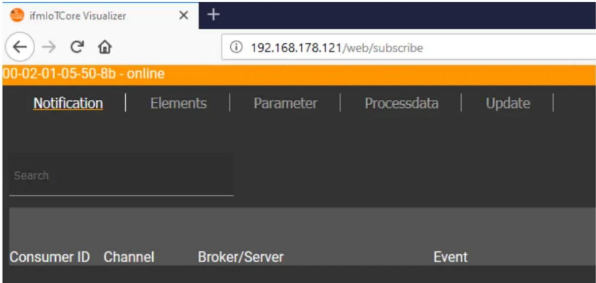
The navigation menu gives the user access to the following functions:
- [Notification]: Creating and managing notifications (subscribe / unsubscribe)
- [Elements]: Searching for elements in device description
• [Parameter]: Configuring IO-Link master
• [Processdata]: Reading and writing process data - [Update]: Updating the firmware of the IO-Link master
Managing notifications
61174
The menu page allows you to perform the following functions
- Creating notifications
• Showing active notifications - Deleting notifications (single, all)
Requirements:
- lot-Core Visualizer has been started.
▶ Click on [Notification].The menu page for managing notifications appears.
The menu page shows all registered notifications in a table
Creating a new notification
61175
A wizard is used to register new notifications.
Requirements:
• The [Notification] menu page is open.
▶ Click on [+] on the right side of the table.
The wizard for the creation of notifications appears.
![00-02-01 05-50 8b online Notification | Elements | Parameter | Processdata | Update | Add Subscription 1 Events 2 Data 3 Transfer Info Event Please choose one event, you want to subscribe to. Search for the Identifier of data element to subscribe to its ( counter 00-02-01-05-50-8b/timer[1]/counter/datachanged counter 00-02-01-05-50-8b/timer[2]/counter/datachanged preset 00-02-01-05-50-8b/connections/mqttconnection/status/preset/datachanged status 00-02-01-05-50-8b/connections/mqttconnection/status/datachanged qos 00-02-01-05-50-8b/connections/mqttconnection/mqttsetup/qos/datachanged preset 00-02-01-05-50-8b/connections/mqttconnection/mqttcmdchannel/status/preset/datachanged CANCEL NEXT >](/content/2026/06/1355794/images/aa2f780acb86a73e19abbf4f8415f6bd02cf68dae3fab0b1b8dd875ef7759add.jpg)
▶ Use the wizard to enter the required notification parameters step by step.
Created notification subscription is displayed in the table.

For cyclical notifications via timer[1] or timer[2], the user also needs to set the interval time of the timer in question.
Deleting a notification
61176
Requirements:
- The [Notification] menu page is open.
- At least one notification is active.
▶ Click on [x] in the column [Unsubscribe].The selected notification will be deleted (unsubscribe).
Searching for elements in the device tree
61177
The [Elements] menu page allows you to search the device description for elements with specific properties (status, profile, name) and to output the results.
Requirements:
- lot-Core Visualizer has been started.
▶ Click on [Elements].The input mask appears.
![00 02 01 05 50-8b - online Notification | Elements | Parameter | Processdata | Update | Search for ... identifier one identifier to search for profile profile(s) to search for: Seperator ; type one type to search for Processdatamaster Deviceinfo Timer[1] Timer[2] lotsetup Fieldbussetup Connections Iolinkmaster Firmware Devicetag 00-02-01-05-50-8 b getidentity 00-02-01-05-50-8b/getidentity type: service profiles: undefined Copy URL gettree 00-02-01-05-50-8b/gettree type: service profiles: undefined Copy URL querytree 00-02-01-05-50-8b/querytree type: service profiles: undefined Copy URL](/content/2026/06/1355794/images/a28a6a34520af16532563f0a74d6891479bc25a8d4e846e328d8beb78c4935da.jpg)
▶ Enter the search criteria of the required item in the [identifier], [profile] and [type] boxes.
▶ Click on [Search for ...].
IoT-Core Visualizer searches device description for elements with selected search criteria.
The result list shows all elements found.
Configuring IO-Link the master
61178
The [Parameter] menu page allows you to configure the IO-Link master.
Available options:
- Reading and writing individual parameters
- Backup and restore the current configuration of the machine.
Requirements:
- lot-Core Visualizer has been started.
▶ Click on [Parameter].The menu page shows the available parameters of the IO-Link master.
Current parameter values are displayed.
Editable parameters can be changed.
![00-02-01-05-50-8b - online Notification | Elements | Parameter | Processdata | Update | Deviceinfo Timer[1] Timer[2] lotsetup Network Fieldbussetup Connections Iolinkmaster Firmware Devicetag lotsetup accessrights lot only Type: enum Namespace: json Encoding: integer Valuation: valuelist: 0: 1: 3: network smobip 192.168.82.2 Type: string Namespace: jeon Encoding: utf-8 Valuation: minlength:](/content/2026/06/1355794/images/26c3895bf6ed78124c17ebf9cf9146fe763398c3f51446b51b9adf6900367cae.jpg)
To change a parameter:
▶ Navigate to the desired parameter in the device description.
▶ Changing the parameter value
▶ Click on the pencil icon to save the change on the IO-Link master.
The changed parameter value is active.
▶ Optional: Repeat the procedure to change further parameter values.
Reading and writing process data
61179
The menu page allows the process data of the IO-Link master and the connected IO-Link devices to be read and written.
Requirements:
- lot-Core Visualizer has been started.
▶ Click on [Processdata].Menu page shows the substructures of the device description that contain process data and events.
The current process values are displayed.
Editable process data can be changed.
![00-02-01-05-50-8b - online Notification | Elements | Parameter | Processdata | Update | Processdatamaster Timer[1] Timer[2] Fieldbussetup Iolinkmaster Port[1] Port[2] Port[3] Port[4] iolinkmaster port[1] portevent FF0200 Type: string Namespace: json Encoding: hexstring iolinkdevice vendorid 310 Type: number Namespace: json Encoding: integer Valuation: min: 0 max: 65535](/content/2026/06/1355794/images/9cae4f2a890ca2637644559e4bb9c542fffa1d944bd2e069dc5875f15eb8d9eb.jpg)
To change the value of a process date:
▶ Navigate to the required process date in the device description.
▶ Change the process value.
▶ Click on the pencil icon to save the change on the IO-Link master.
The changed process value is active.
▶ Optional: Repeat the procedure to change further process values.
Updating the firmware
61180
The [Update] menu page allows you to update the firmware of the IO-Link master:
Requirements:
- lot-Core Visualizer has been started.
▶ Click on [Update].Menu page displays information about the current firmware version.
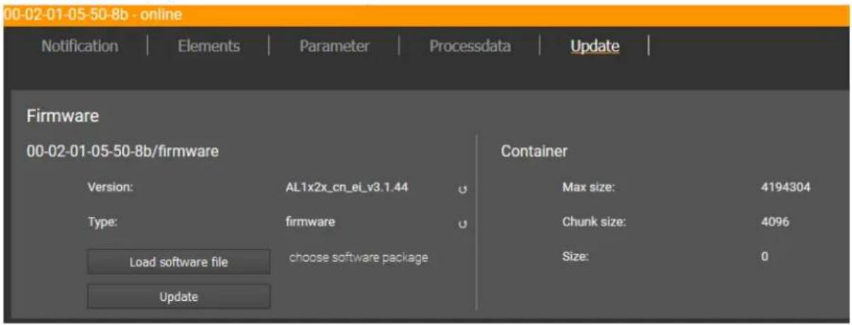
▶ Click on [Load software file] and select a new firmware file (*.bin).
▶ Click on [Update] to start the update process.
The firmware of the IO-Link master will be updated.
The area shows the progress bar.
If the update process has been successful, the IO-Link master will restart automatically.
9.3 PROFINET
Content
Install GSD Files....78
Integrate the IO-Link master in the project....78
Configure the IO-Link master 79
Configure IO-Link ports 80
Configure IO-Link devices 81
Read and write cyclic process data....81
Read I&M datasets....82
Detect diagnostics and alarms 82
34541
On the field bus side, the device can be configured with the following options:
• PROFINET projection software STEP 7 (version 5.5 SP 4 or higher)
• PROFINET projection software TIA portal

Further information about operation and functions of the PROFINET parameter setting software:
▶ Use the help function of the PROFINET projection software!
9.3.1 Install GSD Files
52478
ifm provides a GSD file to integrate the AL1300 in the PROFINET projection software. All parameters, process data and their valid value ranges are defined in the GSD file. The user can download the GSD file from the ifm website (→ www.ifm.com).
To add the IO-Link master to the hardware catalogue of the PROFINET projection software:
▶ Download the GSD file of the AL1300 from the ifm website.
▶ Launch the PROFINET projection software.
▶ Install the GSD file of the AL1300.
Once the GSD file is installed, the AL1300 is in the hardware catalogue in the following folder:
[PROFINET IO] > [Addictional Field Devices] > [IO] > [ifm electronic]

flowchart
graph TD
    A["AL1300"] --> B["IO-Link Master DataLine"]
    B --> C["4 Ports"]
    C --> D["Digital + PQI"]
    C --> E["Disabled"]
    C --> F["IO-Link Input + Output + PQI"]
    C --> G["IO-Link Input + PQI"]
    C --> H["IO-Link Output + PQI"]
    style A fill:#f9f,stroke:#333
    style B fill:#ccf,stroke:#333
    style C fill:#cfc,stroke:#333
    style D fill:#fcc,stroke:#333
    style E fill:#cff,stroke:#333
    style F fill:#ffc,stroke:#333
    style G fill:#fcc,stroke:#333
    style H fill:#cff,stroke:#333
① AL1300
② IO-Link ports
③ PROFINET modules
9.3.2 Integrate the IO-Link master in the project
52479
The AL1300 can be integrated from the hardware catalogue into the project.
▶ Create new project /open project
▶ Create and configure PROFINET controller and coupling units.
▶ Create and configure PROFINET connection.
Drag the [AL1300] node from the hardware catalogue and drop it on the PROFINET connection.
The AL1300 is displayed as part of the PROFINET network.
To integrate the AL1300 in the network infrastructure, the fieldbus interface must be configured correspondingly.
▶ Double click on slot 0 to open the configuration of the AL1300.
▶ Configure the Ethernet interface of the IO-Link master.
Drag the [4 Ports] node from the hardware catalogue and drop it on slot 1 of the IO-Link master.
▶ Save the project.
The IO-Link master is integrated in the project and can be configured.
9.3.3 Configure the IO-Link master
52480
You can access the configuration of the IO-Link master via slot 1.1 of the AL1300.
The parameter [Access Rights] determines which controller instance may have read and write access to the data of the IO-Link master.
To set the parameters of the IO-Link master:
In the project: Double click on slot 1.1 of the AL1300.
▶ Set parameters [Access Rights] as required ( Parameter of the IO-Link master ( p. 92)).
▶ Save the project.

If the parameter [Access Rights] = [PROFINET + IoT] in LR DEVICE and the PROFINET projection software, the parameter values set in the PROFINET projection software will always apply.
If the parameter [Access Rights] = [IoT only] in LR DEVICE, set the parameter [Access Rights] = [Keep settings] in the projection software.
Changes of the parameter [Access Rights] will only be effective after restarting the IO-Link master ( Firmware: Reboot the device ( p. 33)).
9.3.4 Configure IO-Link ports
52481
You can access the configuration of the IO-Link ports via the slots 1.2 ... 1.5 of the AL1300. The following assignment applies
| Slot | IO-Link port of the AL1300 |
| 1.2 | Port X01 |
| 1.3 | Port X02 |
| ... | ... |
| 1.5 | Port X04 |
The available PROFINET modules are defined in the GSD file ( PROFINET modules ( p. 95)). A PROFINET module determines the following properties of an IO-Link port:
- Operating mode (IO-Link, DI, DO, deactivated)
- Type and length of the process data
- Optional data (fail-safe values, device validation, data storage, cycle time, events)
The following table shows the available parameters depending on the selected operating mode:
| Operating mode of the IO-Link ports | Available parameters | ||||||
| Fail-safe mode | Pattern Value | Validation / Data storage | Vendor ID (VID) | Device ID | Port cycle time | IO-Link events | |
| DI: digital input | -- | -- | -- | -- | -- | -- | -- |
| DO: digital output | X | -- | -- | -- | -- | -- | -- |
| IO-Link: input | -- | -- | X | X | X | X | X |
| IO-Link: output | X | X | X | X | X | X | X |
| IO-Link: input and output | X | X | X | X | X | X | X |
-- = not available
X = available
To configure an IO-Link port of the AL1300:
Drag the required PROFINET module from the hardware catalogue and drop it on the slot of the IO-Link port.
▶ Double click on the slot of the IO-Link port
▶ Set the parameters as required ( Parameters of the IO-Link ports ( p. 93)).
▶ Configure unused IO-Link ports with PROFINET module "Deactivated".
▶ Repeat the steps to configure further IO-Link ports.
▶ Save the project.
9.3.5 Configure IO-Link devices
52482
The AL1300 supports the configuration of the connected IO-Link devices via the PROFINET application. The configurable parameters depend on the IO-Link device that is used.

Configurable parameters of the IO-Link devices: → IO Device Description (IODD) of the IO-Link Devices
The following options are available:
| Function block | Description | Notes |
| IO_LINK_DEVICE | Acyclic access to the parameters of an IO-Link device | Input parameter:CAP: Access point for functionAL1300: 0xB400PORT: Slot/sub-slot of the IO-Link interface of the connected IO-Link devicePort X01: 1Port X02: 2...Port X04: 4IOL_INDEX and IOL_SUBINDEX: Index and sub-index of the parameter (depends on the IO-Link device: → IO Device Description (IODD)) |
| IOL_CALL | Acyclic access to the parameters of an IO-Link devices (obsolete) | → IO_LINK_DEVICE |
9.3.6 Read and write cyclic process data
52483
While the IO-Link ports are being configured, IEC addresses are generated automatically for inputs and outputs as well as the PQI byte. To enable access to the cyclic process data in the application, the user must couple the IEC addresses with symbolic variables. This can be done in global lists of variables (STEP 7: [Symbols]; TIA portal: [PLC tags]).
Take the following actions in global lists of variables of the PROFINET controller:
▶ Create a symbolic name and select the data type
▶ Assign an IEC address to the symbolic name
▶ Save the project.
Using the symbolic name, the user can read the inputs and write the outputs from the application.

▶ To check the validity of the cyclic process data, evaluate the PQI byte ( PQI (Port Qualifier Information) ( p. 96)).
Even if the fieldbus connection is interrupted, the PQI byte indicates that the process data is valid. This may have an unintended impact on the control process.
▶ Take suitable measures to detect an interruption of the fieldbus connection.
Read additional digital input
52549
IO-Link ports X01...X04 have a additional digital input (pin 2). The current value is mapped to the PQI byte ( PQI (Port Qualifier Information) ( p. 96)).
9.3.7 Read I&M datasets
52484
I&M0 provide the user with device-specific basic information. This ensures reliable identification of the device, the device's hardware and software components as well as the manufacturer.
The datasets I&M1 to 3 offer the programmer the possibility to store project-specific information on the device.
The programmer can access the I&M0 datasets of the slots 0 and 1 in the PROFINET projection software by means of the following functions:
| Symbol | Description | Notes |
| GET_IM_DATA | Function block for reading the I&M datasets of a deviceGET_IM_DATA only supports the reading of the I&M0 dataset | Input parameters:IM_TYPE = 0 |
| RDREC | Function block for acyclic reading of datasets | Input parameters:I&M0: Index = 0xAFF0I&M1: Index = 0xAFF1I&M2: Index = 0xAFF2I&M3: Index = 0xAFF3 |
| WRREC | Function block for acyclic writing of datasetsObserve access rights on datasets! | Input parameters:I&M1: Index = 0xAFF1I&M2: Index = 0xAFF2I&M3: Index = 0xAFF3 |
9.3.8 Detect diagnostics and alarms
52485

Available alarms and diagnostic messages: → Diagnostic and alarms (→ p. 98)
| Symbol | Operational block | Description |
| I/O_FLT1 | OB82 | Diagnostic alarms |
| I/O_FLT2 | OB83 | Connect/disconnect alarms |
| RACK_FLT | OB86 | Module rack failure |
10 Operation
Content
Using web-based management....83
34061
10.1 Using web-based management
61181
The device has an integrated web server The web server generates a website with the following data:
• Status information of the ports
- Access to product page of connected IO-Link devices (only ifm devices)
• Diagnostic information of the device
- Version information of the installed firmware components
To access the web interface of the IO-Link master:
▶ Connect the IO-Link master to the laptop / PC via the IoT port.
▶ Optional: Check the IP settings of the IoT interface.
▶ Start web browser.
In the address field of the web browser, enter the IP address of the IoT interface and confirm with [ENTER].
The web browser shows the website with the status and diagnostic information of the device.
11 Maintenance, repair and disposal
Content
Cleaning process....84
Updating the firmware 84
Replacing IO-Link device....84
51990
The operation of the unit is maintenance-free.
▶ Dispose of the unit in an environmentally friendly way in accordance with the applicable national regulations when it is no longer used.
11.1 Cleaning process
51991
▶ Clean the surface of the unit when necessary.
▶ Do not use any caustic cleaning agents for this!
▶ In case of severe soiling, use a damp cloth.
▶ Do not use any caustic cleaning agents for this!
11.2 Updating the firmware
61183
The firmware of the IO-Link master can be updated via the IoT Core Visualizer→ Updating the firmware (→ p. 76, → p. 84).
11.3 Replacing IO-Link device
34182
To replace an IO-Link device:
Requirement:
New IO-Link device is with factory settings.
New IO-Link device supports IO-Link standard 1.1 or higher.
1 Set data storage
▶ Set the following parameters of the IO-Link port
- Set Validation and Data Storage to [Type compatible V1.1 device with Restore] or [Type compatible V1.1. device with Backup + Restore]
- Set correct values to [Vendor ID] and [Device ID] according to properties of the IO-Link device.
▶ Save changes.
2 Replace IO-Link device
▶ Disconnect old IO-Link device from IO-Link master.
▶ Connect new IO-Link device with the same IO-Link port of the AL1300.
IO-Link master copies parameter values from the data memory to the new IO-Link device.
12 Factory settings
34509
In the factory settings, the device has the following parameter settings:
| Parameter | Factory setting |
| [IP address] (PROFINET) | 0.0.0.0 |
| [Subnet mask] (PROFINET) | 0.0.0.0 |
| [IP gateway address] (PROFINET) | 0.0.0.0 |
| [IP address] (IoT interface) | 169.254.X.X |
| [Subnet mask] (IoT interface) | 255.255.0.0 |
| [IP gateway address] (IoT interface) | 0.0.0.0 |
| [PROFINET name] | blank |
| Data memory (Data Storage) | empty |
13 Accessories
List of accessories of AL1300: → www.ifm.com > Product page > Accessories
33870
14 Appendix
Content
Technical data 88
PROFINET 92
ifm IoT Core....99
33879
14.1 Technical data
Content
| Application | 88 |
| Electrical data | 88 |
| Inputs / outputs | 88 |
| Inputs | 89 |
| Outputs | 89 |
| Interfaces | 89 |
| Operating conditions | 90 |
| Approvals / tests | 90 |
| Mechanical data | 90 |
| Electrical connection | 91 |
14.1.1 Application
33878
| Application | |
| Application | I/O modules for field applications |
| Daisy-chain function | Fieldbus interface |
14.1.2 Electrical data
33808
| Electrical data | |
| Operating voltage [V] | 20...30 DC; (US; to SELV/PELV) |
| Current Consumption [mA] | 300...3900; (US) |
| Protection class | III |
| Sensor supply US | |
| Max. current load total [A] | 3.6 |
14.1.3 Inputs / outputs
34068
| Inputs / outputs | |
| Total number of inputs and outputs | 8; (configurable) |
| Number of Inputs and Outputs | Number of digital inputs: 8; Number of digital outputs: 4 |
14.1.4 Inputs
34069
| Inputs | |
| Number of digital inputs | 8; (IO-Link port Class A: 4 x 2) |
| Switching level high [V] | 11...30 |
| Switching level low [V] | 0...5 |
| Digital inputs protected against short circuits | yes |
14.1.5 Outputs
34053
| Outputs | |
| Number of digital outputs | 4; (IO-Link port Class A: 4 x 1) |
| Max. current load per output [mA] | 300 |
| Short-circuit protection | yes |
14.1.6 Interfaces
34389
| Interfaces | |
| Communication interface | Ethernet; IO-Link |
| Communication interface | IO-Link; TCP/IP; PROFINET IO |
| Ethernet | |
| Transmission standard | 10Base-T; 100Base-TX |
| Transmission rate [MBit/s] | 10; 100 |
| Protocol | TCP/IP; PROFINET IO |
| Factory settings | IP address: 0.0.0.0Subnet mask: 0.0.0.0Gateway IP address: 0.0.0.0MAC address: see type label |
| IO-Link master | |
| Type of transmission | COM 1 / COM 2 / COM 3 |
| IO-Link revision | V1.1 |
| Number of ports Class A | 4 |
| IoT interface | |
| Transmission standard | 10Base-T; 100Base-TX |
| Transmission rate [Mbits/s] | 10; 100 |
| Protocol | DCP, DCHP, Auto IP |
| Factory settings | IP address: 169.254.X.XSubnet mask: 255.255.0.0Gateway IP address: 0.0.0.0MAC address: see type label |
14.1.7 Operating conditions
34062
| Operating conditions | |
| Applications | Indoor use |
| Ambient temperature [°C] | -25...60 |
| Storage temperature [°C] | -25...85 |
| Max. perm. relative air humidity [%] | 90 |
| Max. height above sea level [m] | 2000 |
| Protection rating | IP 65; IP 66; IP 67 |
| Pollution Degree | 2 |
14.1.8 Approvals / tests
33877
| Approval / tests | |
| EMC | EN 61000-6-2EN 61000-6-4 |
| MTTF [Years] | 90 |
14.1.9 Mechanical data
34050
| Mechanical data | |
| Weight [g] | 301 |
| Materials | Housing: PA; Socket: nickel-plated brass |
14.1.10 Electrical connection
33806
| Voltage supply IN X31 | ||
| Plug and socket connection | M12 | |
| Wiring | 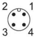 | 1: + 24 V DC (US)2: -3: GND (US)4: - |
| Ethernet IN / OUT X21, X22 | ||
| Plug and socket connection | M12 | |
| Wiring |  | 1: TX+2: RX+3: TX-4: RX-5: - |
| IoT X23 | ||
| Plug and socket connection | M12 | |
| Wiring | 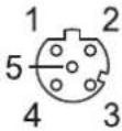 | 1: TX+2: RX+3: TX-4: RX-5: - |
| Process connection IO-Link ports Class A X01...X04 | ||
| Plug and socket connection | M12 | |
| Wiring |  | 1: Sensor supply (US) L+2: DI3: Sensor supply (US) L-4: C/Q IO-Link5: - |
14.2 PROFINET
Content
Parameter data....92
Cyclic data....95
Acyclic data 97
33674
14.2.1 Parameter data
34551
| Slot | Sub-slot | Name | Description |
| 1 | 1 | Master | Parameter data of the IO-Link master (→ Parameter of the IO-Link master (→ p. 92)) |
| 2 | Port X01 | • Parameter data of the IO-Link ports (→ Parameters of the IO-Link ports (→ p. 93)• Fieldbus modules (→ PROFINET modules (→ p. 95)) | |
| 3 | Port X02 | ||
| 4 | Port X03 | ||
| 5 | Port X04 |
Parameter of the IO-Link master
34552
| Parameter | Description | Possible values | |
| [Access Rights] | The access rights to the parameter data, process data and events/diagnostic messages of the IO-Link master and the connected IO-Link devices | PROFINET + IoT | ■ PROFINET and LR DEVICE have read and write access rights to parameters and process data■ PROFINET and LR DEVICE have read access rights to events/alarms |
| PROFINET + IoT (ro) | ■ PROFINET has read and write access rights to parameters and process data■ PROFINET has read access rights to events/alarms■ LR DEVICE only has read access rights to parameters, process data and events/alarms | ||
| PROFINET only | ■ PROFINET has read and write access rights to parameters and process data■ PROFINET has read access rights to events/alarms■ LR DEVICE has no access rights (parameters, process data, events/alarms, web interface, firmware update) | ||
| keep setting | keeps settings | ||
Parameters of the IO-Link ports
34528
| Parameter | Description | Possible values | |
| [Fail-safe mode] | Behaviour of outputs of the port in case the PROFINET connection is interrupted (only valid for operating modes "DO" and "IO-Link") | No Fail Safe | deactivated |
| Fail Safe Reset Value | reset to default values | ||
| Fail Safe Old Value | maintain the most recent valid process value | ||
| Fail Safe with Pattern | set user-defined values | ||
| [Pattern Value]* | required values for the process data in case the connection is interrupted (as hexadecimal value)Pattern depends on the size of the selected PROFINET module | Per byte:0x00 ... 0xFF | |
| [Port cycle time] | Cycle time of the data transmission at the IO-Link port | as fast as possible | The device automatically sets the fastest possible cycle time |
| 2.0 ms...128.0 ms | 2 milliseconds...128 milliseconds | ||
| [Validation / Data Storage] | Supported IO-Link standard and behaviour of the AL1300 when a new IO-Link device is connected to the IO-Link port | no check and clear | no verification of the vendor ID and device IDno data storage |
| Type compatible V1.0 device | IO-Link device is compatible with the V1.0 IO-Link standardVerification whether it is an IO-Link device of the same type (validation via vendor ID and device ID)no data storage | ||
| Type compatible V1.1 device | IO-Link device is compatible with the V1.1 IO-Link standardVerification whether it is an IO-Link device of the same type (validation via vendor ID and device ID)no data storage | ||
| Type compatible V1.1 device with Backup + RestoreType compatible V1.1 device with Restore | IO-Link device is compatible with the V1.1 IO-Link standardVerification whether it is an IO-Link device of the same type (validation via vendor ID and device ID)The IO-Link master saves the parameter values of the connected IO-Link device; modifications of the parameter values are also stored (→ observe the note!)When connecting an IO-Link device with factory settings, the parameter values stored in the IO-Link master are restored automatically on the IO-Link device.IO-Link device is compatible with the V1.1 IO-Link standardVerification whether it is an IO-Link device of the same type (validation via vendor ID and device ID)The IO-Link master stores the parameter values of the connected IO-Link device once if the data memory of the AL1300 is empty.When connecting an IO-Link device with factory settings, the parameter values stored in the IO-Link master are restored automatically on the IO-Link device. | ||
| [Vendor ID (VID)] | ID of the manufacturer that is to be validated | 0 ... 65535 | ID of the manufacturer of the IO-Link device (ifm electronic: 310) |
| [Device ID (DID)] | ID of the IO-Link device that is to be validated | 0 ... 16777215 | ID of the IO-Link device |
| [IO-Link Events] | Enable / disable the transmission of IO-Link events | Disabled | IO-Link won't be transmitted |
| Enabled | IO-Link events will be transmitted | ||
* ... settings are only valid if [Fail Safe Mode] = Fail Safe with Pattern

If the parameter values of an IO-Link device are changed with IO_LINK_DEVICE, the backup mechanism remains ineffective. The changed parameter values are not stored on the IO-Link master.
14.2.2 Cyclic data
Content
PROFINET modules....95
PQI (Port Qualifier Information)....96
33814
PROFINET modules
34539
| Module | Description | |
| IO-Link 32I / 32 O + PQI | IO-Link activated | 32 bytes input and output data and PQI |
| IO-Link 16I / 16O + PQI | 16 bytes input and output data and PQI | |
| IO-Link 8I / 8O + PQI | 8 bytes input and output data and PQI | |
| IO-Link 4I / 4O + PQI | 4 bytes input and output data and PQI | |
| IO-Link 2I / 2O + PQI | 2 bytes input and output data and PQI | |
| IO-Link 1I /1O + PQI | 1 byte input and output data and PQI | |
| IO-Link 1I /15O + PQI | 1 byte input data and 15 bytes output data and PQI | |
| IO-Link 32I + PQI | 32 bytes input data and PQI | |
| IO-Link 16I + PQI | 16 bytes input data and PQI | |
| IO-Link 8I + PQI | 8 bytes input data and PQI | |
| IO-Link 4I + PQI | 4 bytes input data and PQI | |
| IO-Link 2I + PQI | 2 bytes input data and PQI | |
| IO-Link 1I + PQI | 1 byte input data and PQI | |
| IO-Link 32O + PQI | 32 bytes output data and PQI | |
| IO-Link 16O + PQI | 16 bytes output data and PQI | |
| IO-Link 8O + PQI | 8 bytes output data and PQI | |
| IO-Link 4O + PQI | 4 bytes output data and PQI | |
| IO-Link 2O + PQI | 2 bytes output data and PQI | |
| IO-Link 1O + PQI | 1 byte output data and PQI | |
| DI + PQI | IO-Link deactivated | Digital input and PQI |
| DO + PQI | Digital output and PQI | |
| Disabled | deactivated | |
PQI (Port Qualifier Information)
34530
Port Qualifier Information (PQI) contains diagnostic information about the IO-Link port. In addition to the process data, the IO-Link master sends the PQI to the PROFINET controller.
| Bit | |||||||
| 7 | 6 | 5 | 4 | 3 | 2 | 1 | 0 |
| PQ | DE | DA | -- | -- | -- | DI2 | DI4 |
Legend:
■ [DI4] Signal status of the digital input on pin 4 (DI)
FALSE OFF
- [DI2] Signal status of the digital input on pin 2 (if used)
TRUE ON
FALSE OFF
- [DA] Device Available: shows if the IO-Link device has been recognised and if the device is in the "preoperate" or in the "operate" state
TRUE ON
- [DE] Device Error: shows if an error or a warning occurred; Note: The user needs to determine the cause of the fault separately via acyclic services.
FALSE no device
TRUE device detected
- [PQ] Port Qualifier: shows if IO data is valid
FALSE no error
TRUE error detected
FALSE invalid
TRUE valid
14.2.3 Acyclic data
Content
I&M datasets....97
Diagnostic and alarms....98
33868
I&M datasets
34555
The AL1300 supports the following I&M datasets (I&M = Identification & Maintenance):
I&M0 (Slot 0)
34545
| Variable | Description | Access | Size |
| Vendor ID | IO-Link ID of the manufacturer | r | 2 |
| OrderID | Order number of the device (ASCII) | r | 20 |
| Serial number | Serial number of the device (ASCII) | r | 16 |
| Hardware revision | Hardware revision of the device | r | 2 |
| Software revision prefix | Prefix of the software revision of the device (V, R, P, U or T) | r | 1 |
| Software Revision | Software revision (numbers, e.g. x y z in "Vx.y.z") | r | 3 |
| Revision Counter | Revision counter; is incremented with each parameter change | r | 2 |
| Profile ID | ID of sub-module profile (Slot 0: 0x0000) | r | 2 |
| Profile Specific Type | additional value for profile ID; 0, if not used | r | 2 |
| IMVersion | I&M version (default value: 0x0101) | r | 2 |
| IMSupported | Supported I&M datasets (0x1110 for I&M1-3) | r | 2 |
r ... only read
I&M1 (Slot 0)
34543
| Variable | Description | Access | Size |
| TagFunction of submodule | function of the device (ASCII) | r/w | 32 |
| TagLocation of submodule | Location of the device in the plant (ASCII) | r/w | 22 |
r/w ... read and write
I&M2 (Slot 0)
34544
| Variable | Description | Access | Size |
| Installation_Date | Installation date of the device (ASCII) | r/w | 16 |
| reserved | r/w | 38 |
r/w ... read and write
I&M3 (Slot 0)
34550
| Variable | Description | Access | Size |
| Descriptor | Description of the device (ASCII) | r/w | 54 |
r/w ... read and write
I&M0 (Slot 1)
34542
| Variable | Description | Access | Size |
| Vendor ID | IO-Link ID of the manufacturer | r | 2 |
| OrderID | Order number of the device (ASCII) | r | 20 |
| Serial number | Serial number of the device (ASCII) | r | 16 |
| Hardware revision | Hardware revision of the device | r | 2 |
| Software revision prefix | Prefix of the software revision of the device (V, R, P, U or T) | r | 1 |
| Software revision | Software revision (numbers e.g. x y z in "Vx.y.z") | r | 3 |
| Revision counter | Revision counter; is incremented with each parameter change | r | 2 |
| Profile ID | ID of the sub-module profile (Slot 1: 0x4E01 = IOLink) | r | 2 |
| Profile Specific Type | additional value for profile ID; 0, if not used | r | 2 |
| IMVersion | I&M version (default value: 0x0101) | r | 2 |
| IMSupported | Supported I&M datasets (0x0E for I&M1-3) | r | 2 |
r ... read only
Diagnostic and alarms
34533
| ECD code | Name | Description | Type |
| 0x02 | EVNT_CODE_M_PDU_CHECK | Receive frame with CRC error | Alarm |
| 0x1B | EVNT_CODE_S_RETRY | Repetitions detected | Alarm |
| 0x1E | EVNT_CODE_P_SHORT | Short circuit on C/Q cable detected | Diagnostics |
| 0x1F | EVNT_CODE_P_SENSOR | Error in the sensor supply | Diagnostics |
| 0x20 | EVNT_CODE_P_ACTOR | Error in the actuator supply | Diagnostics |
| 0x21 | EVNT_CODE_P_POWER | Error in the power supply of the IO-Link master | Diagnostics |
| 0x28 | EVNT_CODE_DSREADY_NOACTION | Data storage completed, but no action, since CRC was correct | Alarm |
| 0x29 | DS_FAULT_IDENT | Sensor does not match the content of the data memory | Alarm |
| 0x2A | DS_FAULT_SIZE | Sensor parameters too large for data memory | Alarm |
| 0x2B | DS_FAULT_UPLOAD | Error during data memory transmission from the sensor | Alarm |
| 0x2C | DS_FAULT_DOWNLOAD | Error during data memory transmission to the sensor | Alarm |
| 0x2F | DS_FAULT_DEVICE_LOCKED | Error during data storage because the device is blocked | Alarm |
| 0x32 | EVNT_CODES_DSREADY_DOWNLOAD | Parameter transmission to the sensor finished | Alarm |
| 0x33 | EVNT_CODE_DSREADY_UPLOAD | Parameter transmission from the sensor finished | Diagnostics |
14.3 ifm IoT Core
Content
Overview: IoT profile....100
Overview: IoT types....107
Overview: IoT services 108
33803
14.3.1 Overview: IoT profile
Content
| Profile: blob | 100 |
| Profile: deviceinfo | 101 |
| Profile: devicetag | 101 |
| Profile: iolinkdevice_full | 102 |
| Profile: iolinkmaster | 102 |
| Profile: mqttCmdChannel | 103 |
| Profile: mqttCmdChannelSetup | 103 |
| Profile: mqttConnection | 103 |
| Profile: mqttSetup | 104 |
| Profile: network | 104 |
| Profile: parameter | 105 |
| Profile: processdata | 105 |
| Profile: runcontrol | 105 |
| Profile: service | 105 |
| Profile: software | 105 |
| Profile: software/uploadedablesoftware | 106 |
| Profile: Timer | 106 |
34054
Profile: blob
52264
| Element (identifier) | Properties | Mandatory | Comment |
| blobname | ▪ type = data▪ profiles = blob | labels element as device information | |
| ../size | type = data | mandatory | |
| ../chunksize | type = data | mandatory | |
| ../setblobdata | type = service | optional | |
| ../getblobdata | type = service | optional | |
| ../start_stream_set | type = service | optional | |
| ../stream_set | type = service | optional | |
| ../clear | type = service | optional | |
| ../getcrc | type = service | optional | |
| ../getmd5 | type = service | optional | |
| ../getdata | type = service | optional | |
| ../setdata | type = service | optional |
Profile: deviceinfo
34207
| Element (identifier) | Properties | mandatory | Comments |
| deviceinfo | ▪ type = structure▪ profile = deviceinfo | characterises the element as device information | |
| ../devicename | type = data | optional | |
| ../devicefamiliy | type = data | optional | |
| ../devicevariant | type = data | optional | |
| ../devicesymbol | type = data | optional | |
| ../deviceicon | type = data | optional | |
| ../serialnumber | type = data | mandatory | |
| ../productid | type = data | optional | |
| ../productname | type = data | optional | |
| ../productcode | type = data | mandatory | |
| ../producttext | type = data | optional | |
| ../ordernumber | type = data | optional | |
| ../productiondate | type = data | optional | |
| ../productioncode | type = data | optional | |
| ../hwrevision | type = data | mandatory | |
| ../swrevision | type = data | mandatory | |
| ../bootloaderrevision | type = data | optional | |
| ../vendor | type = data | optional | |
| ../vendortext | type = data | optional | |
| ../vendorurl | type = data | optional | |
| ../vendorlogo | type = data | optional | |
| ../productwebsite | type = data | optional | |
| ../supportcontact | type = data | optional | |
| ../icon | type = data | optional | |
| ../image | type = data | optional | |
| ../standards | type = data | optional |
Profile: devicetag
34206
| Element (identifier) | Properties | mandatory | Comments |
| devicetag | ▪ type = structure▪ profile = devicetag | ||
| ../applicationtag | type = data | mandatory | |
| ../applicationgroup | type = data | optional | |
| ../machinecode | type = data | optional | |
| ../tenant | type = data | optional |
Profile: iolinkdevice_full
52265
| Element (identifier) | Characteristics | Mandatory | Comments |
| iolinkdevice | ▪ type = structure▪ profile = iolinkdevice_full | Structure of an IO-Link device | |
| ../vendorid | type = data | mandatory | |
| ../deviceid | type = data | mandatory | |
| ../productname | type = data | mandatory | |
| ../serial | type = data | mandatory | |
| ../applicationspecifictag | type = data | mandatory | |
| ../pdin | type = data | mandatory | |
| ../pdout | type = data | mandatory | |
| ../status | type = data | mandatory | |
| ../iolreadacyclic | type = data | mandatory | |
| ../iolwriteacyclic | type = data | mandatory | |
| ../iolinkevent | type = data | mandatory |
Profile: iolinkmaster
34205
| Element (identifier) | Properties | Mandatory | Comments |
| masterport | type = structureprofile = iolinkmaster | Executable service | |
| ../mode | type = dataprofile = parameter | mandatory | |
| ../comspeed | type = dataprofile = parameter | mandatory | |
| ../mastercycletime_actual | type = dataprofile = parameter | mandatory | |
| ../mastercycletime_preset | type = dataprofile = parameter | mandatory | |
| ../validation_datastorage_mode | type = dataprofile = parameter | mandatory | |
| ../validation_vendorid | type = dataprofile = parameter | mandatory | |
| ../validation_deviceid | type = dataprofile = parameter | mandatory | |
| ../additionalpins_in | type = dataprofile = processdata | optional | |
| ../additionalpins_out | type = dataprofile = processdata | optional | |
| ../portevent | type = data | mandatory | |
| ../iolinkdevice | type = structureprofile = iolinkdevice_full | mandatory |
Profile: mqttCmdChannel
61186
| Element (identifier) | Properties | Mandatory | Comment |
| mqttCmdChannel | type = structureprofile =commChannel | Profile of the MQTT command channel | |
| ../type | type = datadata type = STRING | mandatory | Protocol type of the interface |
| ../status | type = datadata type = STRING | mandatory | Status of the MQTT command channel(possible values: init, running, stopped, error) |
| ../mqttCmdChannelSetup | type = profile | Sub-profile:Profile: mqttCmdChannelSetup(→ p.103) |
Profile: mqttCmdChannelSetup
61187
| Element (identifier) | Properties | Mandatory | Comment |
| mqttCmdChannelSetup | type = structureprofile =mqttCmdChannelSetup | Settings of the MQTT command channel | |
| ../brokerIP | type = datatdata type = STRING | optional | |
| ../brokerPort | type = datadata type = STRING | optional | |
| ../cmdTopic | type = datadata type = STRING | optional | |
| ../defaultReplyTopic | type = datadata type = STRING | optional |
Profile: mqttConnection
61188
| Element (identifier) | Properties | Mandatory | Comment |
| mqttConnection | type = structureprofile =commInterface | MQTT connection in the IoT Core | |
| ../type | type = datadata type = STRING | mandatory | Protocol type of the interface |
| ../status | type = datadata type = STRING | mandatory | global status of the MQTT (possible values: init, running, stopped, error) |
| ../mqttSetup | type = profile | Sub-profile:Profile: mqttSetup(→ p. 104) | |
| ../mqttCmdChannel | type = profile | Sub-profile:Profile: mqttCmdChannel(→ p. 103) |
Profile: mqttSetup
61189
| Element (identifier) | Properties | Mandatory | Comment |
| mqttSetup | ▪ type = structure▪ profile = mqttSetup | Settings of the MQTT command channel | |
| ../QoS | ▪ type = data▪ data type = Number | mandatory | Quality of Service of the MQTT connection |
| ../version | ▪ type = data▪ data type = STRING | mandatory |
Profile: network
52266
| Element (identifier) | Characteristics | Mandatory | Comments |
| network | type = structureprofiles = deviceinfo | Characterises the element as device information | |
| ../macaddress | type = dataprofile = parameter | mandatory | |
| ../ipaddress | type = dataprofile = parameter | optional | |
| ../ipv6address | type = dataprofile = parameter | mandatory | |
| ../subnetmask | type = dataprofile = parameter | mandatory | |
| ../ipdefaultgateway | type = dataprofile = parameter | mandatory | |
| ../dhcp | type = dataprofile = parameter | optional | |
| ../ipversion | type = dataprofile = parameter | optional | |
| ../hostname | type = dataprofile = parameter | optional | |
| ../autonegotiation | type = dataprofile = parameter | optional | |
| ../portspeed | type = dataprofile = parameter | optional | |
| ../enablenetwork | type = service | optional | |
| ../disablenetwork | type = service | optional |
Profile: parameter
34215
The profile is used to mark the elements of type data as parameters (acyclic data). The profile defines no substructure.
Profile: processdata
34225
The profile is used to mark the elements of type data as process data (cyclic data). The profile does not define a substructure.
Profile: runcontrol
61190
| Element (identifier) | Properties | Mandatory | Comment |
| runcontrol | ▪ type = profile▪ profile = runcontrol | Control of the MQTT command channel | |
| ../start | type = service | mandatory | Service: start (→ p. 119) |
| ../stop | type = service | mandatory | Service: stop (→ p. 119) |
| ../reset | type = service | mandatory | Service: Reset (→ p. 116) |
Profile: service
34224
| Element (identifier) | Properties | mandatory | Comments |
| service | ▪ type = service▪ profile = service | Executable service |
Profile: software
34223
| Element (identifier) | Properties | mandatory | Comments |
| software | ▪ type = structure▪ profile = software | characterises the element as software | |
| ../version | type = data | mandatory | |
| ../type | type = data | mandatory | |
| ../status | type = structure | optional | |
| ../diag | type = structure | optional |
Profile: software/uploadedablesoftware
52267
| Element (identifier) | Characteristics | Mandatory | Comments |
| software | type = structureprofiles = software/uploadablesoftware | Software that can be loaded to the device via the IoT Core | |
| ../lastinstall | type = data | optional | |
| ../installhistory | type = data | optional | |
| ../container | type = dataprofile = blob | mandatory | |
| ../preinstall | type = service | optional | |
| ../install | type = service | mandatory | |
| ../postinstall | type = service | optional | |
| ../abortinstall | type = service | optional | |
| ../installstatus | type = data | optional |
Profile: Timer
34226
| Element (identifier) | Properties | Mandatory | Comment |
| timer | ▪ type = structure▪ profile = timer | ||
| ../counter | ▪ type = data▪ profile = parameter | mandatory | |
| ../interval | ▪ type = data▪ profile = parameter | optional | |
| ../start | type = service | optional | |
| ../stop | type = service | optional |
14.3.2 Overview: IoT types
34055
The ifm IoT Core uses the following element types:
| Name | Description |
| structure | Element is a structure element (like a folder in a file system) |
| service | Element is a service that can be addressed from the network |
| event | Element is an event that can be started by the firmware and sends messages. |
| data | Element is a data point |
| device | Root element a device represents |
14.3.3 Overview: IoT services
Content
Service: factoryreset....108
Service: getblobdata....109
Service: getdata....109
Service: getdatamulti 110
Service: getelementinfo....110
Servicet: getidentity 111
Service: getsubscriberlist....112
Service: getsubscriptioninfo....113
Service: gettree 114
Service: install 115
Service: iolreadacyclic....115
Service: iolwriteacyclic....115
Service: querytree 116
Service: reboot 116
Service: Reset 116
Service: setblock 117
Service: setdata....118
Service: signal 118
Service: start....119
Service: start_stream_set....119
Service: stop....119
Service: stream_set....120
Service: subscribe 120
Service: unsubscribe ....121
Service: validation_useconnecteddevice ....121
34056
Service: factoryreset
34184
Name: factoryreset
Description: The service sets the parameters of the device to the factory settings.
Request data (field "data"): none
Response data (field "data"): none
Example:
{
    "code": "request",
    "cid": 4711,
    "adr": "/firmware/factoryreset"
}
Service: getblobdata
52345
Name: getblobdata
Description: The service reads a binary large object (blob).
Applicable to: datastorage
Request data (field "data"):
| Data field | Required field | Data type | Default | Description |
| pos | mandatory | number | 0 | Byte position |
| length | mandatory | number | - | Size of the object (number of bytes) |
Return data (field "data"):
| Data field | Required field | Data type | Default | Description |
| data | mandatory | STRING | 0 | Data to be decoded (BASE64 coded) |
| crc | optional | HEX STRING | CRC of the data after decoding | |
| md5 | optional | HEX STRING | MD5 checksum of the data after decoding |
Service: getdata
34183
Name: getdata
Description: Service reads the value of a data point and provides it.
Request data (field "data"): none
Return data (field "data"):
| Data field | Required field | Data type | Description |
| value | mandatory | STRING | Value of the element/data point |
Example:
{
    "code": "request",
    "cid": 4711,
    "adr": "devicetag/applicationtag/getdata"
}
Service: getdatamulti
34174
Name: getdatamulti
Description: The service sequentially reads the values of several data points and provides them. The value and the diagnostic code are provided for each data point.
Request data (field "data"):
| Data field | Required field | Data type | Description |
| datatosend | mandatory | ARRAY OF STRINGS | List of data points to be requested; data points must support the service getdata ("datatosend":["url1","url2",..., "urlx"]) |
Response data (field "data"): for each requested data point
| Data field | Required field | Data type | Description |
| url | mandatory | STRING | Data point request |
| code | mandatory | INT | Diagnostic code of the request |
| data | mandatory | STRING | Value of the data point |
Service: getelementinfo
52269
Name: getelementinfo
Description: The service reads the properties of an element of the IoT tree.
Applicable to: Objects of the type device
Request data (field "data"):
| Data field | Required field | Data type | Default | Description |
| adr | mandatory | STRING | URL of the element, which properties to be changed |
Return data (field "data"):
| Data field | Required field | Data type | Default | Description |
| identifier | mandatory | STRING | Identifier of the element | |
| type | mandatory | STRING | Type of the element | |
| format | optional | JSON object | blank | Format of the data or the service content |
| uid | optional | STRING | blank | |
| profiles | optional | JSON array | blank | |
| hash | optional | STRING | -- |
Servicet: getidentity
54690
Name: getidentity
Description: The service reads the device information of the AL1300 and issues it.
Request data ("data" field): none
Return data ("data" field):
| Data field | Required field | Data type | Description | |
| iot | Device | Device description as JSON object | ||
| iot.name | mandatory | STRING | ||
| iot.uid | optional | STRING | ||
| iot.version | mandatory | STRING | ||
| iot.catalogue | optional | ARRAY OF OBJECTS | ||
| iot.deviceclass | optional | ARRAY OF STRING | ||
| iot.serverlist | optional | ARRAY OF OBJECTS | ||
| device | optional | AL1300 | ||
| device.serialnumber | optional | Serial number | ||
| device.hwrevision | optional | Hardware version | ||
| device.swrevision | optional | Software version | ||
| device.custom | optional | |||
| Security | optional | Security options | ||
| security.securitymode | optional | ENUM | shows if the security mode is activated | |
| security.authscheme | optional | ENUM | shows the active authentication scheme | |
| security.ispasswordset | optional | BOOL | shows whether a password has been set | |
| security.activeconnection | optional | ENUM | shows the currently used communication interface | |
| · tcp_if | unencrypted http connection at the IoT interface, port 80 | |||
| · tls_if | encrypted https connection at the IoT interface, port 443 | |||
| · fb_if | unencrypted http connection at the fieldbus interface, port 80 | |||
Service: getsubscriberlist
61191
Name: getsubscriberlist
Description: The service provides a list of all active subscriptions.
Request data ("data" field): none
Return data ("data" field): Array with the following data
| Data field | Mandatory field | Data type | Description |
| adr | mandatory | STRING | Data source |
| datatosend | mandatory | ARRAY OF STRINGS | List with URLs of the subscribed data points |
| cid | mandatory | NUMBER | ID of the subscription |
| callbackurl | mandatory | STRING | Address to which IoT Core event notifications are to be sent; |
| duration | mandatory | STRING | Storage duration of the value |
Example:
- Request object:
{
    "code": "request",
    "cid": 4711,
    "adr": "/getsubscriberlist"
}
- Return object:
{
    "cid":4711,
    "data":[
    {
    "adr":"/timer[1]/counter/datachanged/subscribe",
    "datatosend":["/iolinkmaster/port[2]/iolinkdevice/pdin"],
    "cid":1,
    "callbackurl":"http://192.168.0.45:80/temp",
    "duration":"lifetime"},
    {
    "adr":"/timer[1]/counter/datachanged/subscribe",
    "datatosend":["/processdatamaster/temperature","/processdatamaster/voltage"],
    "cid":2,
    "callbackurl":"http://192.168.0.44:80/temp",
    "duration":"lifetime"}
    ]
    "code":200
    }
Service: getsubscriptioninfo
61192
Name: getsubscriptioninfo
Description: The service provides information about an existing subscription (subscribe).

The following parameters of the existing subscription are to be used for the query:
• Value of the identifier cid (e.g. 4711)
• Number of the timer (e.g. timer[1])
• Name of the callback topic (e.g. B. temp)
Request data ("data" field):
| Data field | Mandatory field | Data type | Description |
| callback | mandatory | STRING | Address to which IoT Core event notifications are to be sent; complete URL: http://ipaddress:port/path |
Return data ("data" field):
| Data field | Mandatory field | Data type | Description |
| subscription | mandatory | BOOL | Status of the transferred subscription parameter |
| datatosend | mandatory | ARRAY OF STRINGS | List with subscribed data points |
| cid | mandatory | NUMBER | ID of the subscribe request |
| callbackurl | mandatory | STRING | Address to which IoT Core event notifications are to be sent; complete URL: http://ipaddress:port/path |
Example:
- Request object:
{
    "code": "request",
    "cid": 4711,
    "adr": "/timer[1]/counter/datachanged/getsubscriptioninfo",
    "data": {
    "callback": "http://192.168.0.44:80/temp"
    }
}
- Return object:
{
    "cid": 4711,
    "data": {
    "subscription": true,
    "datatosend": [
    "/iolinkmaster/port[2]/iolinkdevice/productname",
    "/iolinkmaster/port[2]/iolinkdevice/pdin",
    "/processdatamaster/temperature"],
    "callbackurl":"http://192.168.0.44:80/temp",
    "duration":"lifetime"},
    "code":200
    }
}
Service: gettree
61193
Name: gettree
Description: The service reads the device description of the IO-Link master and outputs it as a JSON object. The output can be limited to a subtree of the device description.
Request data ("data" field):
| Data field | Mandatory field | Data type | Description |
| adr | optional | STRING | Root element of the subtree |
| level | optional | STRING | max. level up to which the subtree is outputno entry: all levels will be displayed0: do not display sub-elements ("subs")1: display sub-elements2: display sub-elements up to the 2nd level3: display sub-elements up to the 3rd level...20: display sub-elements up to the 20th level |
Return data ("data" field):
| Data field | Mandatory field | Data type | Description |
| identifier | mandatory | STRING | Identifier of the root element |
| type | mandatory | STRING | Type of the element |
| format | optional | JSON Object | Format of the data content |
| uid | optional | STRING | |
| profiles | optional | JSON-Array | |
| subs | mandatory | JSON-Array | Sub-elements |
| hash | optional | STRING |
Examples:
- output the complete device description
- output the subtree counter[2] of the device description up to the 2nd level
{
    "code": "request",
    "cid": 4,
    "adr": "/gettree"
}
{
    "code": "request",
    "cid": 4,
    "adr": "/gettree"
    "data": {
    "adr": "counter[2]",
    "level": 2
}
Service: install
52343
Name: install
Description: The service installs the firmware stored in the container area of the device.
Applicable to: container
Request data (data): none
Return data (data): none
Service: iolreadacyclic
34178
Name: iolreadacyclic
Description: The service acyclically reads the parameter value of an IO-Link device. The parameter is accessed via IO-Link index and subindex.
Request data (field "data"):
| Data field | Required field | Data type | Description |
| index | mandatory | NUMBER | IO-Link index of the parameter |
| subindex | mandatory | NUMBER | IO-Link subindex of the parameter |
Response data (field "data"):
| Data field | Required field | Data type | Description |
| value | mandatory | STRING | Value of the parameter; Value in hexadecimal format |
Service: iolwriteacyclic
34177
Name: iolwriteacyclic
Description: The service acyclically writes the parameter value of an IO-Link device. The parameter is accessed via IO-Link index and subindex.
Request data (field "data"):
| Data field | Required field | Data type | Description |
| index | mandatory | NUMBER | IO-Link index of the parameter |
| subindex | mandatory | NUMBER | IO-Link subindex of the parameter |
| value | mandatory | STRING | New value of the parameter; Value in hexadecimal format |
Response data (field "data"): none
Service: querytree
61194
Name: querytree
Description: The service searches a device tree for the criteria profile, type and name and outputs a list with the URLs of the elements found. At least one of the search criteria must be specified. The service can only be executed on the root node of the machine.
Return data ("data" field):
| Data field | Mandatory field | Data type | Description |
| profile | optional | STRING | Profile of the searched element |
| type | optional | STRING | Type of the searched element |
| name | optional | STRING | Type of the searched element |
Return ("data" field):
| Data field | Mandatory field | Data type | Description |
| urlList | mandatory | Array | Array with URLs of the found elements; URLs are separated by commas |
Service: reboot
34176
Name: reboot
Description: The service reboots the device.
Request data (field "data"): none
Return data (field "data"): none
Example:
{
    "code": "request",
    "cid": 4,
    "adr": "firmware/reboot"
}
Service: Reset
61195
Name: Reset
Description: The service resets a connection to the initialisation state.
Request data ("data" field): none
Return data ("data" field): none
Example:
{
    "code": "request",
    "cid": 4711,
    "adr": "/connections/mqttConnection/MQTTSetup/mqttCmdChannel/status/reset"
}
Service: setblock
34186
Name: setblock
Description: The service simultaneously sets the values of several data points of a structure.
Request data (field "data"):
| Data field | Required field | Data type | Description |
| datatoset | mandatory | ARRAY OF OBJECTS | List of data points and their new values; data points must support the service setdata |
| consistent | optional | BOOL |
Response data (field "data"): none
Example:
Request:
{
    "code": "request",
    "cid": 4711,
    "adr": "iotsetup/network/setblock",
    "data": {
    "datatoset": {
    "ipaddress": "192.168.0.6",
    "subnetmask": "255.255.255.0",
    "ipdefaultgateway": "192.168.0.250",
    "dhcp": 0
    }
    }
}
Response:
{
    "cid": 4711,
    "code": 233
}
Service: setdata
34195
Name: setdata
Description: The service sets the value of the data point.
Request data ("data" field):
| Data field | Mandatory field | Data type | Description |
| newvalue | mandatory | STRING | New value of the element/data point |
| duration | mandatory | STRING | Duration of value storagelifetime: Value is saved with IoT Core; Value remains valid even after restart of the deviceuptime: Value is saved until the next restart of the device |
Return data ("data" field): none
Example:
{"code": "request",
"cid":4711,
"adr": "devicetag/applicationtag/setdata",
"data": {
"newvalue": "ifm IO-Link master
"duration": "lifetime"}
}
Service: signal
33819
Name: signal
Description: The service starts the flashing of the status LEDs of the AL1300.
Request data (field "data"): none
Return data (field "data"): none
Example:
{
    "code": "request",
    "cid": 4711,
    "adr": "firmware/signal"
}
Service: start
61196
Name: start
Description: The service starts a connection.
Request data ("data" field): none
Return data ("data" field): none
Example:
{
    "code": "request",
    "cid": 4711,
    "adr": "/connections/mqttConnection/MQTTSetup/mqttCmdChannel/status/start"
}
Service: start\_stream\_set
52342
Name: start_stream_set
Description: The service starts the sequential transfer of multiple data segments.
Applicable to: Objects of type data
Request data (data):
| Data field | Required field | Data type | Default | Description |
| size | mandatory | STRING | Total size of data to be transferred (number of bytes) |
Return data (data): none
Service: stop
61197
Name: stop
Description: The servicestops a connection.
Request data ("data" field): none
Return data ("data" field): none
Example:
{
    "code": "request",
    "cid": 4711,
    "adr": "/connections/mqttConnection/MQTTSetup/mqttCmdChannel/status/stop"
}
Service: stream\_set
52341
Name: stream_set
Description: The service transfers a data segment.
Applicable to: Objects of type data
Request data (data):
| Data field | Required field | Data type | Default | Description |
| value | mandatory | BIN (BASE64) | * | Segment of binary data (BASE64 coded) |
Return data (data): none
Service: subscribe
61198
Name: subscribe
Description: The service subscribes to the values of data points. The data points to be subscribed are transferred as a list. The IoT Core sends changes to the data sink defined in callback.

CSV formatted notifications can only be transmitted using the TCP protocol via an activated and configured MQTT channel.
Request data ("data" field):
| Data field | Mandatory field | Data type | Description |
| callback | mandatory | STRING | Address to which IoT Core event notifications are to be sent; URL format:JSON: http://ipaddress:port/pathJSON: ws://pathJSON: mqtt://ipadress:port/topicCSV: tcp://ipaddress:port/path |
| datatosend | mandatory | ARRAY OF STRINGS | List from URLs of data elements; Elements must support getdata |
| codec | optional | STRING | Format of the returned datajson: JSON formattedcsv: CSV with standard separator (,)csv0: CSV formatted with comma separator (,)csv1: CSV formatted with semicolon separator (;) |
| DURATION | mandatory | STRING | Duration of value storagelifetime: Value is saved with IoT Core; Value remains valid even after restart of the deviceuptime: Value is saved until the next restart of the deviceonce: send only one notification, user must unsubscribe immediately |
Return data ("data" field): none
Notification: JSON
{
    "code": "event",
    "cid": 4711,
    "adr": "",
    "data": {
"eventno":"EventNo",
"srcurl":"SrcURL",
"payload":{
"eventurl":{"code":EventStatus,"data":EventData},
"datapointurl_1":{"code":DataStatus_1,"data":DataValue_1},
"datapointurl_2":{"code":DataStatus_2,"data":DataValue_2},
...}}
}
Notification: CSV
SrcURL, EventNo, EventStatus, EventData, DataStatus_1, DataValue_1, DataStatus_2, DataValue_2, ...
- SrcURL: Source of the event (data point on which subscribe command was listed)
• EventNo: Event number
• EventStatus: Status code of the event - EventData: Event data
- DataStatus_1: Status code of the 1st element in list datatosend
- DataValue_1: Value of the 1st element in list datatosend
- DataStatus_2: Status code of the 2nd element in list datatosend
- DataValue_2: Value of the 2nd element in list datatosend
...
Service: unsubscribe
34197
Name: unsubscribe
Description: The service deletes an existing subscription. The service unsubscribe is successful if cid and the callback address are registered for an active subscription (subscribe). If the STRING "DELETE" is provided in callback, the IO-Link master deletes all active subscriptions.
Request data (field "data"):
| Data field | Required field | Data type | Description |
| callback | mandatory | STRING | Address to which IoT Core event notifications are to be sent; complete URL: http://ipaddress:port/path |
Response data (field "data"): none
Service: validation\_useconnecteddevice
52340
Name: validation_connecteddevice
Description: The service checks, whether Device ID and Vendor ID of the connected IO-Link device match with the values of the datapoints ../validation_vendorid and ../validation_deviceid.
Applicable to: Objects of type structure
Request data (data): none
Return data (data): none
15 Index
A
Access the ifm IoT Core 37
Accessories 86
Acyclic data....97
Appendix....87
Application 88
Approvals / tests 90
C
Change history....6
Cleaning process....84
Communication, parameter setting, evaluation....11
Configuration 23
Configure IO-Link devices 34, 81
Configure IO-Link ports 80
Configure the IO-Link master 79
Configuring IO-Link the master 74
Configuring the MQTT command channel 66
Connecting IO-Link devices for Class A operation....16
Connecting IO-Link devices for Class B operation....17
Connecting the device....18
Connecting the IoT port....15
Connecting the PROFINET ports 15
Creating a new notification....71
Cyclic data 95
D
Deleting a notification ....72
Detect diagnostics and alarms 82
Diagnostic and alarms 98
Digital inputs 12
E
Electrical connection....14, 91
Electrical data....88
Ethernet ports 20
Example
Activate security mode 46
Browsing device description....42
Change name of the IO-Link master....59
Change the parameter value of an IO-Link device....55
Changing a subscription....61
Checking subscriptions....63
Clone the Data Storage of an IO-Link port....49
Configuring the MQTT command channel....67
GET request....37
output subtree 41
POST request....39
Publish the temperature to an MQTT broker 69
Read IO-Link process data (operating mode 51
Read several parameter values of the IO-Link master simultaneously .....42
Read the parameter value of an IO-Link device ....54
Reading digital input (operating mode....52
Reading properties of an element....40
Request with authentication 46
reset password....47
Subscribing notifications via WebSocket....64
Subscribing to notifications....43, 60
Subscribing to notifications in CSV format....62
Unsubscribing from notifications....62
Update firmware....58
Writing digital output (operating mode....52
Writing IO-Link value (operating mode 51
Explanation of Symbols 5
F
Factory settings 85
Fieldbus
Configure IP settings....29
Configuring IP settings 48
Firmware
Reboot the device....33
Reset device to factory settings....33
First steps 40
Function 10
G
Gateway
Reading device information 57
Reading status and diagnostic information....57
Resetting, rebooting and localising the device....56
Setting the application tag....59
Updating the firmware 58
General 7
General functions....40
GET request ....37
|
I&M datasets....97
I&M0 (Slot 0)....97
I&M0 (Slot 1) 98
I&M1 (Slot 0)....97
I&M2 (Slot 0)....97
I&M3 (Slot 0)....98
ifm IoT Core 35,99
Info
Show device information....33
Inputs 89
Inputs / outputs 88
Install GSD Files....78
Integrate the IO-Link master in the project....78
Intended use....9
Interfaces 89
Internet of Things (IoT) 11
IO-Link 11
IO-Link devices
Accessing parameters....54
Indicating IO-Link events....56
Reading an writing device information....56
IO-Link ports 16
Activate data transfer to LR AGENT or LR SMARTOBSERVER....30
Configure operating mode....31
Configuring data transfer to LR AGENT or LR SMARTOBSERVER .....51
Configuring device validation and data storage....49
Indicating port events 54
Reading / writing process data 51
Set the device validation and data storage....32
Setting the operating mode of pin 4 (US) 48
IO-Link Ports (Class A) 21
IO-Link supply 12
IoT
Configure IP settings....26
Configure security mode....26
Configure the interface to LR AGENT or LR SMARTOBSERVER....29
Configuring access rights 27,44
Configuring IP settings 44
Configuring security mode....45
Configuring the LR AGENT or LR SMARTOBSERVER interface 45
IoT Core
Diagnostic codes 39
General information....36
IoT port....21
IT security 8
L
LED indicators 20
Legal and copyright information ....5
LR DEVICE 24
M
Maintenance, repair and disposal 84
Managing notifications....71
Mechanical data....90
Mount the device 13
Mounting 13
MQTT support....66
N
Note
Connection states....67
Security mode 45
Notes....14
0
Offline parameter setting 25
Operating and display elements....19
Operating conditions....90
Operation 83
Outputs 89
Overview 19
IoT profile 100
IoT services....108
IoT types 107
P
Parameter data 92
Parameter of the IO-Link master 92
Parameter setting ....11
Parameters of the IO-Link ports 93
POST request....38
PQI (Port Qualifier Information)....96
Preliminary note....5
Profile
blob 100
deviceinfo....101
devicetag....101
iolinkdevice_full....102
iolinkmaster....102
mqttCmdChannel 103
mqttCmdChannelSetup 103
mqttConnection....103
mqttSetup....104
network....104
parameter....105
processdata....105
runcontrol....105
service....105
software 105
software/uploadedablesoftware....106
Timer....106
PROFINET 11,77,92
PROFINET modules....95
Programmers' notes 36
Purpose of the document 5
R
Read additional digital input 82
Read and write cyclic process data....81
Read I&M datasets 82
Reading and writing process data....75
Remarks......25
Replacing IO-Link device....84
Required background knowledge....7
S
Safety instructions ....7
Safety symbols on the device....7
Searching for elements in the device tree....73
Security mode....11
Service
factoryreset 108
getblobdata 109
getdata....109
getdatamulti....110
getelementinfo....110
getsubscriberlist 112
getsubscriptioninfo 113
gettree....114
install....115
iolreadacyclic....115
iolwriteacyclic 115
querytree....116
reboot....116
Reset....116
setblock....117
setdata 118
signal....118
start....119
start_stream_set 119
stop 119
stream_set 120
subscribe....120
unsubscribe....121
validation_useconnecteddevice....121
Servicet
getidentity....111
Setting the storage duration 43
Set-up 22
Status LEDs....20
Subscribing to notifications....60
T
Technical data 88
U
Updating the firmware 76,84
Using the IoT-Core Visualizer....70
Using Web Socket 64
Using web-based management....83
V
Visual indication....12
Voltage supply 21
VPN connection....25
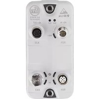

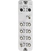
- Inhaltsverzeichnis
- Preliminary note 5
- Safety instructions 7
- Intended use 9
- Function 10
- Mounting 13
- Electrical connection
- Operating and display elements
- Set-up 22
- Configuration 23
- LR DEVICE 24
- ifm IoT Core 35
- PROFINET....77
- Operation 83
- Maintenance, repair and disposal 84
- Factory settings 85
- Accessories 86
- Appendix 87
- Index 122
- Preliminary note
- Content
- Legal and copyright information
- Purpose of the document
- Explanation of Symbols
- WARNING
- CAUTION
- NOTICE
- Change history
- Safety instructions
- General
- Required background knowledge
- Safety symbols on the device
- IT security
- NOTICE!
- Intended use
- Function
- Communication, parameter setting, evaluation
- IO-Link
- PROFINET
- Internet of Things (IoT)
- Security mode
- Parameter setting
- Visual indication
- Digital inputs
- IO-Link supply
- Mounting
- Mount the device
- Notes
- Connecting the PROFINET ports
- Connecting the IoT port
- IO-Link ports
- Connecting IO-Link devices for Class A operation
- Wiring information:
- Connecting IO-Link devices for Class B operation
- Connecting the device
- Overview
- LED indicators
- Status LEDs
- Ethernet ports
- IoT port
- Voltage supply
- IO-Link Ports (Class A)
- Set-up
- Further steps:
- Configuration
- LR DEVICE
- Remarks
- Offline parameter setting
- VPN connection
- IoT: Configure IP settings
- IoT: Configure security mode
- IoT: Configuring access rights
- IoT: Configure the interface to LR AGENT or LR SMARTOBSERVER
- Fieldbus: Configure IP settings
- IO-Link ports: Activate data transfer to LR AGENT or LR SMARTOBSERVER
- IO-Link ports: Configure operating mode
- IO-Link ports: Set the device validation and data storage
- Info: Show device information
- Firmware: Reset device to factory settings
- Firmware: Reboot the device
- Configure IO-Link devices
- Requirements:
- Select IO-Link master
- Add IO-Link device
- Configure IO-Link device
- ifm IoT Core
- Programmers' notes
- IoT Core: General information
- Access the ifm IoT Core
- GET request
- Example: GET request
- POST request
- Example: POST request
- IoT Core: Diagnostic codes
- First steps
- General functions
- Example: Reading properties of an element
- Example: output subtree
- Example: Read several parameter values of the IO-Link master simultaneously
- Example: Browsing device description
- Setting the storage duration
- Example: Subscribing to notifications
- IoT: Configuring access rights
- IoT: Configuring IP settings
- IoT: Configuring the LR AGENT or LR SMARTOBSERVER interface
- IoT: Configuring security mode
- Note: Security mode
- Example: Activate security mode
- Activate security mode
- Set required password
- Example: Request with authentication
- Example: reset password
- Fieldbus: Configuring IP settings
- IO-Link ports: Setting the operating mode of pin 4 (US)
- IO-Link ports: Configuring device validation and data storage
- Example: Clone the Data Storage of an IO-Link port
- Preparations
- Read Data Storage of IO-Link port
- Restore Data Storage:
- Transfer Data Storage strings
- IO-Link ports: Configuring data transfer to LR AGENT or LR SMARTOBSERVER
- IO-Link ports: Reading / writing process data
- Example: Read IO-Link process data (operating mode "IO-Link")
- Example: Writing IO-Link value (operating mode "IO-Link")
- Example: Writing digital output (operating mode "DO")
- Example: Reading digital input (operating mode "DI")
- IO-Link ports: Indicating port events
- IO-Link devices: Accessing parameters
- Example: Read the parameter value of an IO-Link device
- Example: Change the parameter value of an IO-Link device
- IO-Link devices: Reading an writing device information
- IO-Link devices: Indicating IO-Link events
- Gateway: Resetting, rebooting and localising the device
- Gateway: Reading device information
- Gateway: Reading status and diagnostic information
- Gateway: Updating the firmware
- Example: Update firmware
- Task:
- Solution:
- Start the transfer of the firmware
- Load the firmware into the flash memory of the IO-Link master
- Install firmware
- Gateway: Setting the application tag
- Example: Change name of the IO-Link master
- Subscribing to notifications
- Example: Changing a subscription
- Example: Subscribing to notifications in CSV format
- Example: Unsubscribing from notifications
- Example: Checking subscriptions
- Using Web Socket
- Example: Subscribing notifications via WebSocket
- MQTT support
- Configuring the MQTT command channel
- Note: Connection states
- Example: Configuring the MQTT command channel
- Example: Publish the temperature to an MQTT broker
- Using the IoT-Core Visualizer
- Managing notifications
- Creating a new notification
- Deleting a notification
- Searching for elements in the device tree
- Configuring IO-Link the master
- To change a parameter:
- Reading and writing process data
- Updating the firmware
- PROFINET
- Install GSD Files
- Integrate the IO-Link master in the project
- Configure the IO-Link master
- Configure IO-Link ports
- Configure IO-Link devices
- Read and write cyclic process data
- Read additional digital input
- Read I&M datasets
- Detect diagnostics and alarms
- Operation
- Using web-based management
- Maintenance, repair and disposal
- Cleaning process
- Updating the firmware
- Replacing IO-Link device
- Requirement:
- Set data storage
- Replace IO-Link device
- Factory settings
- Accessories
- Appendix
- Technical data
- Application
- Electrical data
- Inputs / outputs
- Operating conditions
- Approvals / tests
- Mechanical data
- PROFINET
- Parameter data
- Parameter of the IO-Link master
- Cyclic data
- PROFINET modules
- PQI (Port Qualifier Information)
- Acyclic data
- I&M datasets
- ifm IoT Core
- Overview: IoT profile
- Profile: parameter
- Profile: processdata
- Profile: runcontrol
- Profile: service
- Profile: software
- Overview: IoT types
- Overview: IoT services
- Service: factoryreset
- Service: getblobdata
- Service: getdata
- Service: getdatamulti
- Service: getelementinfo
- Servicet: getidentity
- Service: getsubscriberlist
- Example:
- Service: getsubscriptioninfo
- - Request object:
- - Return object:
- Service: gettree
- Name: gettree
- Examples:
- Service: install
- Service: iolreadacyclic
- Service: iolwriteacyclic
- Service: querytree
- Service: reboot
- Service: Reset
- Service: setblock
- Response data (field "data"): none
- Service: setdata
- Return data ("data" field): none
- Service: signal
- Service: start
- Service: start\_stream\_set
- Service: stop
- Service: stream\_set
- Service: subscribe
- Notification: CSV
- Service: unsubscribe
- Name: unsubscribe
- Service: validation\_useconnecteddevice
- Index
- A
- C
- D
- E
- Example
- F
- Fieldbus
- Firmware
- G
- Gateway
- |
- Info
- IO-Link devices
- IoT
- L
- M
- N
- 0
- P
- R
- S
- T
- U
- V
Brand : IFM
Model : AL1300
Category : Industrial interface