
AC6000 - Industrial interface IFM - Free user manual and instructions
Find the device manual for free AC6000 IFM in PDF.


| Product Type | IO-Link Master with AS-Interface Gateway |
| Model | AC6000 |
| Brand | IFM |
| Number of IO-Link Ports | 4 (Class A) |
| IO-Link Revision | V1.1 (compatible with 1.0) |
| AS-Interface Version | 3.0 |
| Supply Voltage AS-i | 18...31.6 V DC |
| Supply Voltage AUX | 20...30 V DC (SELV/PELV) |
| Current Consumption (AUX) | 300...1500 mA |
| Max. Current from AS-i | 100 mA |
| Protection Rating | IP 65 / IP 66 / IP 67 |
| Ambient Temperature | -25 to 60 °C |
| Storage Temperature | -25 to 85 °C |
| Weight | 247 g |
| Housing Material | PA (Polyamide), brass nickel-plated sockets |
| Number of Digital Inputs | 8 (4 ports x 2, configurable) |
| Number of Digital Outputs | 4 (1 per port, configurable) |
| Max. Output Current per Channel | 300 mA |
| Short-Circuit Protection | Yes (inputs and outputs) |
| Communication Interfaces | IO-Link (COM1/COM2/COM3), AS-Interface |
| Configuration Options | AS-i master, command interface, CODESYS library |
| Data Storage | Yes (automatic backup and restore for IO-Link devices) |
| Firmware Update | Via AS-Interface network |
| Mounting | 2 x M5 screws, torque 1.8 Nm |
Frequently Asked Questions - AC6000 IFM
User questions about AC6000 IFM
0 question about this device. Answer the ones you know or ask your own.
Ask a new question about this device
Download the instructions for your Industrial interface in PDF format for free! Find your manual AC6000 - IFM and take your electronic device back in hand. On this page are published all the documents necessary for the use of your device. AC6000 by IFM.
USER MANUAL AC6000 IFM
Operating Instructions
IO-Link Master with AS-Interface Interface
StandardLine
4 Ports
IP 65 / IP 66 / IP 67
AC6000
Firmware: 2.4.x or higher
English
Contens
1 Preliminary note 4
1.1 Legal and copyright information....4
1.2 Symbols used....5
1.3 Warnings used ....5
1.4 User documentation for this device....6
1.5 Modification history 6
2 Safety instructions 7
2.1 General 7
3 Functions and features 8
4 Function 9
4.1 IO-Link....9
IO-Link supply 9
4.2 AS-interface 9
4.3 Parameter setting....9
4.4 Visual indication ....10
5 Mounting 11
5.1 Mounting the device....11
6 Electrical connection 12
6.1 Notes....12
6.2 IO-Link ports....13
6.2.1 Connecting IO-Link devices for Class A operation....13
6.2.2 Connecting IO-Link devices for Class B operation 14
6.3 Connecting the unit....15
7 Operating and display elements 16
7.1 Overview 16
7.2 LED indicators....17
7.2.1 Status LEDs 17
7.2.2 Voltage supply....17
7.2.3 IO-Link ports (Class A)....18
8 Set-up 19
9 Configuration 20
9.1 Notes....21
9.1.1 Device structure 21
9.1.2 Options for parameter setting....21
9.1.3 Using the command interface....22
9.2 Addressing the AS-i slave of the AC6000....24
9.2.1 Addressing via AS-i master 24
9.2.2 Addressing with addressing unit....25
9.3 Adjusting the gateway profile 26
9.3.1 Example: Setting the gateway profile 27
9.4 Configuring IO-Link ports 28
9.4.1 Note: Device validation and data storage....28
9.5 Reading / writing parameters of the IO-Link devices 29
9.5.1 Example: Reading parameter....29
9.5.2 Example: Writing parameter....31
9.6 Reading / writing process data....33
9.7 Reading identification and diagnostic information 33
9.8 Reading IO-Link events 33
9.9 Resetting IO-Link master 33
9.10 Updating the firmware....34
10 Maintenance, repair and disposal 35
10.1 Cleaning process ....35
10.2 Replacing IO-Link device 35
11 Factory settings 36
12 Accessories 37
13 Appendix 38
13.1 Technical data....39
13.1.1 Application....39
13.1.2 Electrical data....39
13.1.3 Inputs / outputs....39
13.1.4 Inputs....40
13.1.5 Outputs....40
13.1.6 Interfaces....40
13.1.7 Operating conditions 41
13.1.8 Approvals / Tests....41
13.1.9 AS-i classification....41
13.1.10 Mechanical data 41
13.1.11 Electrical connection 42
13.2 AS-Interface 43
13.2.1 Mapping: inputs and outputs of the IO-Link ports....44
13.3 Command interface....61
13.3.1 Structure of the command interface 61
13.3.2 Overview: Acyclic commands....64
13.3.3 0x01: Read IO-Link Port Configuration Errors....65
13.3.4 0x02: Write IO-Link Port Configuration....66
13.3.5 0x03: Read IO-Link Port Configuration....70
13.3.6 0x04: Read Input Process Data....73
13.3.7 0x05: Read Output Process Data....75
13.3.8 0x06: Write Output Process Data....77
13.3.9 0x07: Read Diagnosis Data....79
13.3.10 0x08: Factory Defaults....81
13.3.11 0x09: Set IO-Link Failsafe Data....82
13.3.12 0x0A: Write Parameter 84
13.3.13 0x0B: Read Parameter....87
13.3.14 0x0C: Read Device Name, Serial Number, HW and SW Revisions....89
13.3.15 0x0D: Update Firmware....91
14 Index 93
1 Preliminary note
Content
Legal and copyright information ....4
Symbols used 5
Warnings used....5
User documentation for this device ....6
Modification history....6
33203
1.1 Legal and copyright information
33117
© All rights reserved by ifm electronic gmbh. No part of this manual may be reproduced and used without the consent of ifm electronic gmbh.
All product names, pictures, companies or other brands used on our pages are the property of the respective rights owners:
• AS-i is the property of the AS-International Association, (→ www.as-interface.net)
• CAN is the property of the CiA (CAN in Automation e.V.), Germany (→ www.can-cia.org)
- CODESYS™ is the property of the 3S – Smart Software Solutions GmbH, Germany (→ www.codesys.com)
- DeviceNet ^™ is the property of the ODVA ^™ (Open DeviceNet Vendor Association), USA (→ www.odva.org)
- EtherNet/IP ^ is the property of the ODVA ^TM
- EtherCAT ^® is a registered trade mark and patented technology, licensed by Beckhoff Automation GmbH, Germany
- IO-Link ^ is the property of the PROFIBUS Nutzerorganisation e.V., Germany ( www.io-link.com)
- ISOBUS is the property of the AEF – Agricultural Industry Electronics Foundation e.V., Deutschland (→ www.aef-online.org)
- Microsoft ^ is the property of the Microsoft Corporation, USA (→ www.microsoft.com)
- Modbus® is the property of the Schneider Electric SE, France (→ www.schneider-electric.com)
- PROFIBUS ^® is the property of the PROFIBUS Nutzerorganisation e.V., Germany (→ www.profibus.com)
• PROFINET ^® is the property of the → PROFIBUS Nutzerorganisation e.V., Germany
- Windows ^ is the property of the Microsoft Corporation, USA
1.2 Symbols used
58277

Important note
Non-compliance can result in malfunction or interference

Information
Supplementary note
▶ ... Request for action
... Reaction, result
→ ... "see"
abc Cross-reference
123 Decimal number
0x123 Hexadecimal number
0b010 Binary number
[...] Designation of pushbuttons, buttons or indications
1.3 Warnings used
58278

WARNING
Warning of serious personal injury.
Death or serious irreversible injuries may result.

CAUTION
Warning of personally injury.
Slight reversible injuries may result.

NOTICE!
Warning of damage to property
1.4 User documentation for this device
59298
Available user manuals for this device:
| Name Description | |
| Operating instructions | Installation, electrical connectionSet-upParameter setting and command interfaceMaintenance, repair, disposal |
| Programming manual | Parameter setting with CODESYS function library |

ifm provides the documents for download on its website: → www.ifm.com
1.5 Modification history
34492
| Version Topic | Date | |
| 00 | New creation of document | 04/2020 |
2 Safety instructions
Content
General 7
28333
2.1 General
59299
- The device described is a subcomponent for integration into a system. The system architect is responsible for the safety of the system. The system architect undertakes to perform a risk assessment and to create documentation in accordance with legal and normative requirements to be provided to the operator and user of the system. This documentation must contain all necessary information and safety instructions for the operator, the user and, if applicable, for any service personnel authorised by the architect of the system.
- Read this document before setting up the product and keep it during the entire service life.
- The product must be suitable for the corresponding applications and environmental conditions without any restrictions.
- Only use the product for its intended purpose (→ Functions and features (→ p. 8)).
- If the operating instructions or the technical data are not adhered to, personal injury and/or damage to property may occur.
- The manufacturer assumes no liability or warranty for any consequences caused by tampering with the device or incorrect use by the operator.
- Installation, electrical connection, set-up, programming, configuration, operation and maintenance of the product must be carried out by personnel qualified and authorised for the respective activity.
- Protect units and cables against damage.
3 Functions and features
59300
The device may only be used for the following purposes:
• as IO-Link master to configure and control the connected IO-Link devices
• as gateway between IO-Link devices and the AS-Interface network.
The device is designed for use outside of a control cabinet.
▶ Only use the device within the limits of the technical data.
4 Function
Content
IO-Link 9
AS-interface 9
Parameter setting 9
Visual indication....10
33836
4.1 IO-Link
59301
The device offers the following IO-Link functions:
• IO-Link master (IO-Link revision 1.0 and 1.1)
• 4 IO-Link ports to connect IO-Link devices
• IO-Link ports X01...X04
■ Pin 4: configurable as deactivated, digital input (DI), digital output (DO), IO-Link
■ Pin 2: additional digital input (supply voltage: AUX)
4.1.1 IO-Link supply
59302
The device offers 4 supplies for IO-Link devices (sensors, actuators).
The ports IO-Link ports X01...X04 are Ports Class A.
The following IO-Link ports have common short-circuit monitoring: X01 and X02, X03 and X04
The device ensures fire protection for connected IO-Link devices by providing an energy-limited circuit at the IO-Link ports (to IEC61010-1 and Class 2 to UL1310).
4.2 AS-interface
51953
The device offers the following AS-Interface functions:
• providing the functions of a AS-i Slave
• Supported AS-i version: 3.0
- Gateway to transfer the process and parameter data between the connected IO-Link devices and the higher-level AS-i master
4.3 Parameter setting
51954
The device offers the following configuration options:
- Addressing and parameter setting of the integrated AS-i slaves via AS-i master
- Parameter setting of the IO-Link master via command interface or using CODESYS programming software
- Parameter setting of the connected IO-Link devices via command interface or using CODESYS programming software
• Storage of parameter sets of the connected IO-Link devices for automatic recovery (data storage)
4.4 Visual indication
51955
The device displays the following indications:
• Status and error indication of the gateway and the AS-Interface connection
• Status indication of the supply voltages AS-i and AUX
- Status, error and short circuit/overload indication of the IO-Link ports
- Status indication of the additional digital inputs (pin 2)
5 Mounting
Content
Mounting the device ....11
34058
5.1 Mounting the device
34059

▶ Disconnect the system from power before installation.
▶ For installation choose a flat mounting surface.
▶ Please observe the maximum tightening torque.
▶ Fix the unit to the mounting surface using 2 M5 mounting screws and washers.
- Tightening torque: 1.8 Nm
6 Electrical connection
Content
Notes 12
IO-Link ports 13
Connecting the unit....15
33805
6.1 Notes
51957

A qualified electrician must connect the unit.
The national and international for regulations setting up electrical equipment must be complied with.
The unit is only suitable for operation using SELV/PELV voltages.
▶ Please note the information concerning IO-Link wiring!
This unit contains components that may be damaged or destroyed by electrostatic discharge (ESD).
▶ Please observe the required precautions against electrostatic discharge!
The IP rating of the overall system depends on the protection ratings of the individual devices, the applied connection elements and the corresponding protective caps.
▶ Provide cables with a strain relief depending on the mounting conditions to avoid excessive strain on the installation points and the M12 connections.
▶ Ensure correct fit and proper assembly of the M12 connecting parts. If these instructions are not complied with, the specified protection rating cannot be guaranteed.
For UL applications:
To connect the IO-Link master and the IO-Link devices, only use UL-certified cables of the CYJV or PVVA category with a minimum temperature of 80 °C (75 °C in case of maximum ambient temperature of 40 °C).
Wiring: → Technical data (→ p. 39)
By means of basic insulation according to EN61010-1, the circuits are separated from each other and from device surfaces that could be touched (secondary circuit with 30 V DC maximum, supplied from mains circuit up to 300 V overvoltage category II).
By means of basic insulation according to EN61010-1, the communication interfaces are separated from each other and from device surfaces that could be touched (secondary circuit with 30 V DC maximum, supplied from mains circuit up to 300 V overvoltage category II). They are designed for network environment 0 according to IEC TR62102.
6.2 IO-Link ports
51958
The IO-Link ports of the AC6000 meet the requirements of the IO-Link specifications 1.0 to 1.1.2.
▶ Please note the information concerning IO-Link wiring!
▶ Cover unused sockets with M12 protective caps (art. no.: E73004).
■ Tightening torque 0.6...0.8 Nm
6.2.1 Connecting IO-Link devices for Class A operation
59303
Wiring information:
- The connected IO-Link devices must be supplied exclusively via the IO-Link master.
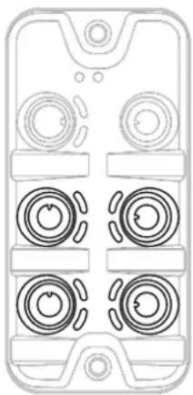
natural_image
Front view of a mobile phone case with four circular buttons arranged in a grid (no text or symbols)▶ Connect the connectors of the IO-Link devices with the M12 sockets of the IO-Link ports X01...X04.
■ Tightening torque: 0.6...0.8 Nm
■ Maximum cable length per IO-Link port: 20 m
▶ To connect the devices, use M12 connectors with protection rating IP 65 / IP 66 / IP 67 or higher (→ Accessories (→ p. 37)).
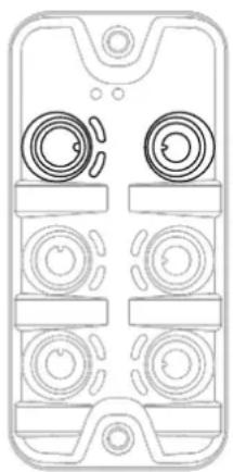
6.2.2 Connecting IO-Link devices for Class B operation
51960
Notes on wiring:
- For Class B operation, the IO-Link device must be supplied with an additional auxiliary voltage UA using a Y connection cable.

WARNING
Non-compliance with the electrical separation of the circuits
Risk of fire!
▶ Ensure that the external supply UA is galvanically separated from the circuit of the IO-Link Master by assuring basic insulation (according to IEC 61010-1, secondary circuit with 30 V DC maximum, supplied from mains circuit up to 300 V of overvoltage category II).
▶ Ensure that the IO-Link devices and the connection technology support the galvanic separation.

In case of operation as port class B, the additional digital input of the IO-Link port (pin 2) is not available!

natural_image
Top-down schematic of a mobile phone case with four circular buttons and control knobs (no text or labels)▶ Connect the connectors of the IO-Link devices via a Y connection cable with the M12 sockets of the IO-Link ports X01...X04.
▶ Connect the Y cable to 24 V DC (20...30 V SELV/PELV)
■ Tightening torque: 0.6...0.8 Nm
▶ To connect the devices, use M12 connectors with protection rating IP 65 / IP 66 / IP 67 or higher (→ Accessories (→ p. 37))!
6.3 Connecting the unit
51961

The AS-i voltage supplies the communication electronics.
▶ Connect the AS-i voltage input to AS-i power supplies only!
The AUX voltage supplies the IO-Link master.
In case of cables that are longer than 25 m, take the voltage drop and the necessary minimum supply voltage of 20 V into consideration!
natural_image
Top-down schematic of a mobile phone casing showing front panel, top panel with circular buttons, and bottom panel with rectangular buttons (no text or symbols)▶ Disconnect power.
▶ Connect the device via the M12 socket to the AS-i supply voltages AS-i (18...31,6 V DC) and AUX (24 V DC (20...300 V SELV/PELV)).
- Tightening torque: 0.6...0.8 Nm.
- Recommended maximum cable length: 25 m
▶ To connect the device, use M12 connectors with at least protection rating IP 65 / IP 66 / IP 67 (→ Accessories (→ p. 37)).
Optional: Supply of an additional AS-i device (daisy chain)
▶ Connect an additional AS-i device to the M12 socket X22 of the AC6000 (loop-through function).
- Tightening torque: 0.6...0.8 Nm
- Recommended maximum cable length: 25 m
▶ To connect the device, use M12 connectors with at least protection rating IP 65 / IP 66 / IP 67 (→ Accessories (→ p. 37)).
7 Operating and display elements
Content
Overview....16
LED indicators 17
34063
7.1 Overview
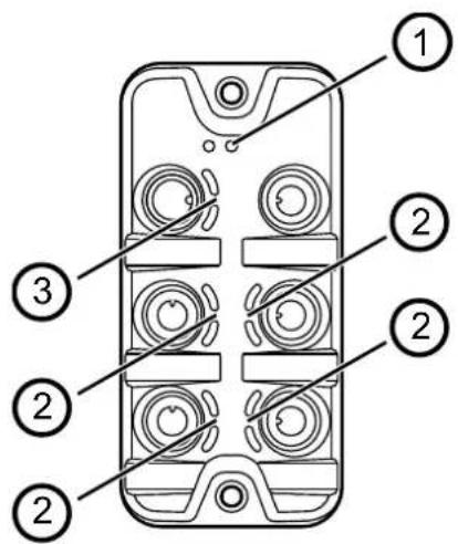
51963
① Status LEDs RDY and FLT (→ Status LEDs (→ p. 17))
② IOL and DI status LEDs of the IO-Link port (X01...X04 (→ IO-Link ports (Class A) (→ p. 18))
③ Status LEDs AS-i and AUX of the voltage supply (X21) ( Voltage supply ( p. 17))
7.2 LED indicators
The device only has the following LED indicators:
34047
7.2.1 Status LEDs
The RDY LED indicates the status of the gateway.
The FLT LED shows the status of the AS-Interfaceconnection.
| Status LED Description | |||
| RDY | green | on | Status: OK |
| flashes 5 Hz Status: Error | |||
| flashes (200 ms on, 800 ms off) | Status: Firmware update is running | ||
| off | Status: Gateway not running or gateway booting | ||
| FLT | red | on | AS-i connection error or AS-i default address is set |
| off error-free | |||
7.2.2 Voltage supply
51965
The port for the voltage supply (X21) has the AS-i and AUX LEDs. The LEDs indicate the status of the voltage supply:
| Status LED Description | |||
| AS-i | green | on | AS-i voltage supply is connected |
| off | no supply voltage or connected supply voltage is too low | ||
| AUX | green | on | Voltage supply AUX is connected |
| off | no supply voltage or connected supply voltage is too low | ||
7.2.3 IO-Link ports (Class A)
52923
Each IO-Link port Class A has 2 LEDs marked as IOL and DI. The LEDs indicate the status of the IO-Link port.
| Status LED Description | |||
| IOL | yellow | off | Port configured as DI / DO: pin 4 (C/Q) = OFF |
| on | Port configured as DI / DO: pin 4 (C/Q) =ON | ||
| green | flashes 1 Hz | Port configured as IO-Link: no IO-Link device detected | |
| flashes 2 Hz | Port configured as IO-Link: PROOPERATE state | ||
| on | Port configured as IO-Link: OPERATE state | ||
| red | flashes 1.2 Hz | Port configuration error or short circuit or overload | |
| on Transmission error | |||
| DI | yellow | off | Digital input : pin 2 (DI) = OFF |
| on Digital input: pin 2 (DI) = ON | |||
8 Set-up
59304
When the supply voltage has been switched on, the AC6000 starts with the factory settings. The display elements signal the current operating status ( Operating and display elements ( p. 16)).
To enable configuration of the gateway and IO-Link functions, the device must be integrated into the AS-i network.
▶ Addressing the basic AS-i slave of the AC6000 ( Addressing the AS-i slave of the AC6000 ( p. 24)).
▶ Connect the addressed AC6000 with the AS-i network.
AS-i master shows configuration error.
▶ Re-configure the AS-i network.
AC6000 has a valid AS-i address.
AS-i master switches to operating mode "Protected mode".
After successful configuration, the IO-Link master transfers the process data of the factory set gateway profile (mapping of the process data: ID1 = 0xF (→ p. 58)). The AS-i master can access the AC6000 via the set AS-i address.
Further steps:
- Setting the gateway profile of the AC6000.
- Configuring the IO-Link master and the IO-Link ports.
9 Configuration
Content
Notes 21
Addressing the AS-i slave of the AC6000 24
Adjusting the gateway profile....26
Configuring IO-Link ports....28
Reading / writing parameters of the IO-Link devices 29
Reading / writing process data 33
Reading identification and diagnostic information....33
Reading IO-Link events....33
Resetting IO-Link master....33
Updating the firmware 34
33858
9.1 Notes
Content
| Device structure | 21 |
| Options for parameter setting | 21 |
| Using the command interface | 22 |
9.1.1 Device structure

flowchart
graph LR
    A["AS-i Master"] --> B["①"]
    B --> C["AC600n"]
    C --> D["②"]
    D --> E["IO-Link Device"]
    D --> F["IO-Link Device"]
    D --> G["IO-Link Device"]
    D --> H["IO-Link Device"]
    D --> I["IO-Link Device"]
    style A fill:#f9f,stroke:#333
    style B fill:#ccf,stroke:#333
    style C fill:#cfc,stroke:#333
    style D fill:#fcc,stroke:#333
    style E fill:#ffc,stroke:#333
    style F fill:#ffc,stroke:#333
    style G fill:#ffc,stroke:#333
    style H fill:#ffc,stroke:#333
    style I fill:#ffc,stroke:#333
① The AS-i slave component of the AC6000 sets the following features:
- Address range of the AC6000 in the AS-i network (max. 5 related AS-i addresses)
- Type and scope of the process data transferred between the AS-i master and IO-Link ports
② The IO-Link component of the AC6000 includes the IO-Link master as well as the IO-Link ports.
9.1.2 Options for parameter setting
59307
The AS-i slave of the AC6000 is configured via functions of the AS-i master. This includes the following settings:
- Addressing the AS-i slave
- Setting the gateway profile (= setting the ID1 code of the basic AS-i slave)
To set the parameters of the IO-Link master and the IO-Link ports of the AC6000 and the connected IO-Link devices, the access to process and diagnostic data as well as maintenance functions, the following options are available:
- Command interface (→ Using the command interface (→ p. 22)
• Function library for CODESYS (→ programming manual)
9.1.3 Using the command interface
51971
The AC6000 has a command interface. Via the interface and using acyclic commands, the user can access parameters, process and diagnostic data as well as events of the IO-Link master. In addition, the command interface offers simple maintenance functions.

Documentation of the command interface: → Command interface (→ p. 61)
Requirements for access to the command interface of the AC6000:
• AC6000 is integrated in the AS-i network.
• AS-i master is in the operating mode "Protected mode".
Principle of the command processing
51973
The basic AS-i slave of the AC6000 has the CTT1 profile S-7.4. It supports the AS-i command interface. The user can use the following AS-i commands to access the IO-Link master using acyclic IO-Link commands:
• Write Parameter String (S-7.4): Send IO-Link command request
- Read Parameter String (S-7.4): Reading IO-Link command request
- Read Diagnosis (S-7.4): Read status information about the command processing
The IO-Link command request is sent encapsulated in the data range of the AS-i command "Write Parameter String (S-7.4)" to the basic AS-i slave of the AC6000.
The basic AS-i slave verifies the received data and indicates their validity in the status bit [CMD Req]. After that, the basic AS-i slave gives the IO-Link command request to the IO-Link master.
The IO-Link master executes the IO-Link command. After that, it provides the IO-Link command response. The availability of the IO-Link command response is indicated in the status bit [CMD Resp]. [CMD Req] and [CMD Resp] are part of the status information of the basic AS-i slave ( Mapping: Status information ( p. 59)). The status information can be read using the AS-i command "Read Diagnosis (S-7.4)" or via the cyclic input data of the basic AS-i slave.
The provided IO-Link command response will be read back using the AS-i command "Read Parameter String (S-7.4)". The IO-Link command response is stored in the data range of the AS-i command.

Documentation of the acyclic AS-i commands: → User manual of the AS-i master
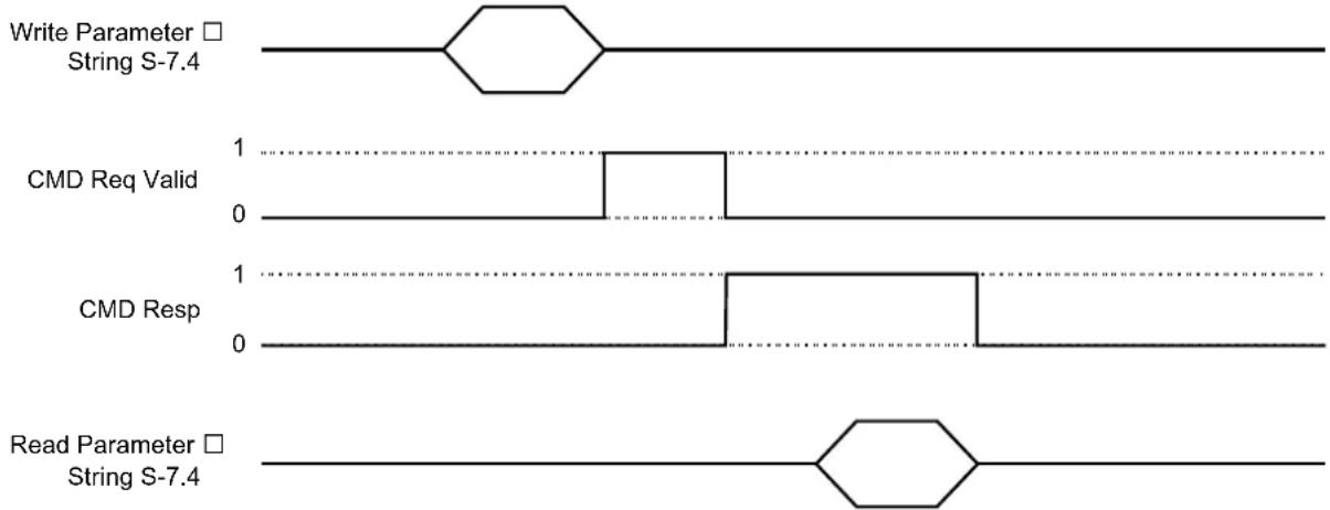
Procedure: Sending acyclic command to the IO-Link master
51974
The following figure shows the chronological sequence of an acyclic IO-Link command by means of the AS-i commands:
flowchart
graph TD
    A["Write Parameter □ String S-7.4"] --> B{Binary State}
    B --> C["1"]
    B --> D["0"]
    C --> E["CMD Req Valid"]
    D --> F["CMD Resp"]
    E --> G["1"]
    F --> H["0"]
    G --> I["Read Parameter □ String S-7.4"]
    H --> J["1"]
    I --> K["0"]
General process:
1 Send command request
▶ Send the IO-Link command request to the basic AS-i slave using the command "Write Parameter String (S-7.4)".
The basic AS-i slave passes the IO-Link command request to the IO-Link master.
IO-Link master executes command.
The IO-Link master provides the IO-Link command response.
2 Verify the validity of the command request
▶ Read the cyclic input data of the basic AS-i slave or Read the status information of the basic AS-i slave using the AS-i command "Read Diagnosis (S-7.4)"
▶ Verify the bit [CMD Req Valid] (→ Mapping: Status information (→ p. 59)).
If [CMD Req Valid] == 0: Command request invalid; verify and repeat step 1
If [CMD Req Valid] == 1: Command request valid; continue with step 3
3 Verify the availability of the command response
▶ Read the cyclic input data of the basic AS-i slave
or
Read the status information of the basic AS-i slave using the AS-i command "Read Diagnosis (S-7.4)"
▶ Verify the bit [CMD Resp] ( Mapping: Status information ( p. 59)).
If [CMD Resp] == 0: Command response not available; Repeat step 3
If [CMD Resp] == 1: Command response available; continue with step 4
4 Read command response
▶ Request the IO-Link command response of the basic AS-i slave using the AS-i command "Read Parameter String (S-7.4)".
The AS-i slave sends the command response to the AS-i master.
After the AS-i command "Read Parameter String (S-7.4)" has been executed, the bit [CMD Resp] = 0 is set
▶ Verify the status of the command.
▶ Optional: Read requested data.
9.2 Addressing the AS-i slave of the AC6000
51979
The user can use the following options when addressing the basic AS-i slave:
• AS-i master: → Addressing via AS-i master (→ p. 24)
• AS-interface addressing unit AC1154: → Addressing with addressing unit (→ p. 25)

Depending on the set ID1 code, the AC6000 takes up a space of up to 5 connected AS-i addresses in the AS-i network. ( Adjusting the gateway profile ( p. 26)).
The following restrictions apply for the addressing:
| ID1 code basic AS-i slave | additional AS-i slaves | valid address range of the basic AS-i slaves |
| 0xF 0 1...31 | ||
| 0xB, 0xD 1 1...30 | ||
| 0x1, 0x2, 0x3, 0xA, 0xC | 2 | 1...29 |
| 0x8, 0x9 3 1...28 | ||
| 0x4, 0x5, 0x6, 0x7 4 1...27 |
▶ Take the valid address range into consideration when addressing the basic AS-i slave!
9.2.1 Addressing via AS-i master
59308

Functions for addressing: → User documentation of the AS-i master
▶ Connect AC6000 with the AS-i network.
AS-i master shows configuration error.
▶ Assign an free address to the AC6000 with functions of the AS-i master.
▶ Re-configure the AS-i network.
AC6000 has a valid AS-i address.
AS-i master switches to operating mode "Protected mode".
Cyclic process data is transferred between the AS-i master and AC6000.
9.2.2 Addressing with addressing unit
59309

Detailed information about AS-Interface addressing unit AC1154: → www.ifm.com

If the AC1154 is used for the addressing, the AC6000 must be supplied with the AUX supply voltage. For this purpose, ifm offers the Y cable EVC844 as an accessory ( Accessories ( p. 37)).
▶ Connect the AC1154 with the ASi OUT (X22) port using the Y cable EVC844.
▶ Connect the Y cable EVC844 to 24 V DC (20...30 V SELV/PELV)
▶ Make sure the Y cable is properly connected!
▶ Connect AC6000 with the addressing unit.
▶ Assign a free AS-i address to the AC6000.
▶ Connect the addressed AC6000 with the AS-i network.
AS-i master shows configuration error.
▶ Re-configure the AS-i network.
AC6000 has a valid AS-i address.
AS-i master switches to operating mode "Protected mode".
Cyclic process data is transferred between the AS-i master and AC6000.
9.3 Adjusting the gateway profile
59310
The gateway profile determines which process data of the IO-Link ports is transmitted cyclically between the IO-Link master and the AS-i network. The user can adjust various gateway profiles using the ID1 code of the basic AS-i slave. The process data is transmitted in the analogue channels of the additional AS-i slaves ( Mapping: inputs and outputs of the IO-Link ports ( p. 44)).
In the factory settings, the AC6000 is a single AS-i slave. It has the CTT1 profile S-7.4.E (ID1 = 0xF) with 4 analogue input channels. In each channel, 2 bytes of input data of an IO-Link port are transmitted (mapping: → ID1 = 0xF (→ p. 58)).

Setting the ID1 code of the basic AS-i slave is done using the functions of the AS-i master ( user documentation of the AS-i master).
Independent of the set gateway profile, the user can access all process data of the connected IO-Link devices with acyclic commands.
▶ Set the ID1 code of the basic AS-i slave.
AS-i master shows configuration error.
▶ Re-configure the AS-i network.
AC6000 is a participant of the AS-i network.
AS-i master works in the "Protected mode".
9.3.1 Example: Setting the gateway profile
51981
Task:
Each of the first two words of the input and output data of the IO-Link at the ports X01...X03 are to be transmitted.
Solution:
- Required ID1 code: 0x7
• Mapping of the process data (details: → ID1 = 0x7 (→ p. 51)):
| Add. Slave (n+4) | Add. Slave (n+3) | Add. Slave (n+2) | Add. Slave (n+1) | Basic Slave (n)S-7.4.E | |||||||||||||
| Channel 3 | Channel 2 | Channel 1 | Channel 0 | Channel 3 | Channel 2 | Channel 1 | Channel 0 | Channel 3 | Channel 2 | Channel 1 | Channel 0 | Channel 3 | Channel 2 | Channel 1 | Channel 0 | ||
| Port X01 | 1 0 | 1 0 | → Status-Informatio nen | ||||||||||||||
| Port X02 | 1 0 | 1 0 | |||||||||||||||
| Port X03 1 | 0 | 1 0 | |||||||||||||||
| Port X04 | 1 0 | 1 0 | |||||||||||||||
green = input data
rot = output data
• The following process data will be cyclically transmitted between IO-Link master and AS-i master:
- Word 0 and 1 of the input and output data at port X01
■ Word 0 and 1 of the input and output data at port X02
■ Word 0 and 1 of the input and output data at Port X03
■ Word 0 and 1 of the input and output data at port X04 (remain unused)
• Number of Additional AS-i slaves: 4
- Valid address range for Basic AS-i slave: 1...27 (1 Basic AS-i slave + 4 Additional AS-i slaves = 5 consecutive AS-i addresses)
9.4 Configuring IO-Link ports
59311
The configuration of an IO-Link port consists of the following parameters:
- Operating mode (IO-Link, digital input, digital output, disabled)
• Cycle time of the data transmission between the IO-Link master and the IO-Link device
• Data storage of the IO-Link device configuration for automatic recovery
• Device validation for connected IO-Link devices (validation ID)
• Vendor and device ID for active device validation (Vendor ID / Device ID) - Fail-safe values in case the AS-i connection is interrupted
Available commands:
| Name Description Reference | ||
| 0x03: Reading IO-Link port configuration | Read current configuration of all IO-Link ports | 0x03: Read IO-Link Port Configuration (→ p. 70) |
| 0x02: Write IO-Link Port Configuration | Write the configuration of all IO-Link ports | 0x02: Write IO-Link Port Configuration (→ p. 66) |
| 0x09: Set IO-Link Failsafe Data | Set fail-safe values | 0x09: Set IO-Link Failsafe Data (→ p. 82) |
| 0x01: Reading IO-Link Port Configuration Errors | Read configuration errors of the IO-Link ports | 0x01: Read IO-Link Port Configuration Errors (→ p. 65) |
9.4.1 Note: Device validation and data storage
59312
The user can choose how the IO-Link ports are to behave with regard to the device validation and the storage / recovery of parameter data of the connected IO-Link device.
The following options are available:
| Option | Validation of the IO-Link device | Storage of the parameter values | Recovery of the parameter values |
| [No check and clear] | no | no | no |
| [Type compatible V1.0 device] | yes, test the compatibility with IO-Link standard V1.0 | no no | |
| [Type compatible V1.1 device] | yes, test the compatibility with IO-Link standard V1.1 | no no | |
| [Type compatible V1.1 device with Backup + Restore] | yes, test the compatibility with IO-Link standard V1.1 and identity of design (vendor ID and device ID) | yes, automatic storage of the parameter values; changes of the current parameter values will be stored | yes, recovery of the parameter values when connecting an identical IO-Link device with factory settings |
| [Type compatible V1.1 device with Restore] | yes, test the compatibility with IO-Link standard V1.1 and identity of design (vendor ID and device ID) | no, there is no automatic storage changes of the current parameter values will not be stored | yes, recovery of the parameter values when connecting an identical IO-Link device with factory settings |

The options only apply if the IO-Link port is in the operating mode "IO-Link".
For options [Type compatible V1.1 device with Backup + Restore] and [Type compatible V1.1 device with Restore]: If the vendor ID and device ID are changed in the online mode, the data memory will be deleted and a new backup of the parameter values of the connected IO-Link device will be created in the IO-Link master.
9.5 Reading / writing parameters of the IO-Link devices
59313
The parameters of an IO-Link device can be accessed by means of ISDU (Indexed Service Data Unit).

The "IO-Link Device Description" (IODD) contains all available parameters of an IO-Link device as well as their indexes and sub-indexes: → Operating instructions of the IO-Link device
Requirements:
• IO-Link port is in the operating mode "IO-Link".
• IO-Link device is connected to the IO-Link port of the AC6000.
Available commands:
| Name Description Reference | ||
| 0x0B: Read Parameter | Read the parameters of an IO-Link device | 0x0B: Read Parameter (→ p. 87) |
| 0x0A: Write Parameter | Write the parameters of an IO-Link device | 0x0A: Write Parameter (→ p. 84) |
9.5.1 Example: Reading parameter
51984
Task:
The parameter of the IO-Link device at IO-Link port X02 is to be read (AS-i master: 1, AS-i slave address: 2, Index: 15000, sub-index: 0; parameter length: 172 bytes)
Solution:
Send read command with "Write Parameter String (S-7.4) to AC6000; read the parameter value that has been read with 2x "Read Parameter String (S-7.4).
Course:

flowchart
graph TD
    A["Write Parameter □ String S-7.4"] --> B["Hexagon"]
    C["CMD Req Valid"] --> D["1"]
    E["CMD Resp"] --> F["1"]
    G["Read Parameter □ String S-7.4"] --> H["Hexagon"]
    I["Read Parameter □ String S-7.4"] --> J["Hexagon"]
    B --> K["0"]
    D --> L["0"]
    H --> M["0"]
    J --> N["0"]
1 Request parameter value
▶ Send AS-i command "Write Parameter String (S-7.4)" to basic AS-i slave.
▶ Save the request of the IO-Link command "Read Parameter" in the data range:
| Parameter Value Note | ||
| Block ID | 0x00 | single command |
| Command ID | 0x0B | "Read Parameter" command |
| Target ID | 0x02 | IO-Link port X02 |
| Data Length | 0x03 | Index (2 bytes) + sub-index (1 byte) |
| Index (MSB) 0x3A | ||
| Index (LSB) 0x98 | ||
| Sub-index 0x00 |
Basic AS-i slave passes "Read Parameter" command request to IO-Link master.
IO-Link master executes command.
IO-Link master saves 1. Segment of the parameter value in "Read Parameter" command response.
2 Verify the availability of the IO-Link command response
▶ Read the status information of the basic AS-i slave.
▶ If [CMD Resp] == 0: IO-Link command response not available; Repeat step 2.
▶ If [CMD Resp] == 1: IO-Link command response available; continue with step 3
3 Read parameter value (first segment)
▶ Send AS-i command "Read Parameter String (S-7.4)" to basic AS-i slave.
▶ Data range of the command request: → step 1 (bytes 0...6)
Data range of the command response contains "Read Parameter" command response (first segment):
| Parameter Value Note | ||
| Block Counter | 0x00...0xFF | cons. number |
| Block-ID | 0x01 | first segment; follow further segments |
| Response Data Length | 0x96 | 150 bytes to return data |
| Command Status | 0x01 | Execution OK (→ error codes) |
| Response Data[0...149] | per byte: 0x00...0xFF | Parameter value (bytes 0...149) |
After the read command is finished, the IO-Link master sets the bit [CMD Resp] = 0.
IO-Link master saves the second segment of the parameter value in "Read Parameter" command response.
4 Verify the availability of the IO-Link command response
▶ Read status information of the basic AS-i slave ( step 2)
▶ If bit [CMD Resp] == 0: IO-Link command response not available; Repeat step 4.
▶ If bit [CMD Resp] == 1: IO-Link command response available; continue with step 5
5 Read parameter value (first Segment)
▶ Send AS-i command "Read Parameter String (S-7.4)" to basic AS-i slave.
▶ Data range of the command request: → Step 1 (bytes 0...6)
Data range of the command response contains "Read Parameter" command response (second segment):
| Parameter | value | Note |
| Block Counter | 0x00...0xFF | cons. number |
| Block-ID | 0xFF | last segment |
| Response Data Length | 0x16 | 172 bytes to return data |
| Command Status | 0x01 | Execution OK (→ error codes) |
| Response Data[150...172] | per byte: 0x00...0xFF | Parameter value (bytes 150...172) |
After the read command is finished, the IO-Link master sets the bit [CMD Resp] = 0.
9.5.2 Example: Writing parameter
51985
Task:
Parameter of the IO-Link devices on IO-Link port X02 is to be written (AS-i master: 1, AS-i slave address: 2, Index: 15000, sub-index: 0; parameter length: 192 bytes)
Solution:
Send parameter value with 2x "Write Parameter String (S-7.4)" to AC6000; verify the success of each write operation with "Read Parameter String (S-7.4)"
Course:

flowchart
graph TD
    A["Write Parameter □ String S-7.4"] --> B["Hexagon"]
    B --> C["Hexagon"]
    C --> D["Hexagon"]
    D --> E["Hexagon"]
    E --> F["Hexagon"]
    F --> G["Hexagon"]
    G --> H["Hexagon"]
    H --> I["Hexagon"]
    I --> J["Hexagon"]
    J --> K["Hexagon"]
    K --> L["Hexagon"]
    L --> M["Hexagon"]
    M --> N["Hexagon"]
    N --> O["Hexagon"]
    O --> P["Hexagon"]
    P --> Q["Hexagon"]
    Q --> R["Hexagon"]
    R --> S["Hexagon"]
    S --> T["Hexagon"]
    T --> U["Hexagon"]
    U --> V["Hexagon"]
    V --> W["Hexagon"]
    W --> X["Hexagon"]
    X --> Y["Hexagon"]
    Y --> Z["Hexagon"]
    Z --> AA["Hexagon"]
    AA --> AB["Hexagon"]
    AB --> AC["Hexagon"]
    AC --> AD["Hexagon"]
    AD --> AE["Hexagon"]
    AE --> AF["Hexagon"]
    AF --> AG["Hexagon"]
    AG --> AH["Hexagon"]
    AH --> AI["Hexagon"]
    AI --> AJ["Hexagon"]
    AJ --> AK["Hexagon"]
    AK --> AL["Hexagon"]
    AL --> AM["Hexagon"]
    AM --> AN["Hexagon"]
    AN --> AO["Hexagon"]
    AO --> AP["Hexagon"]
    AP --> AQ["Hexagon"]
    AQ --> AR["Hexagon"]
    AR --> AS["Hexagon"]
1 Send first segment of the parameter value
▶ Send AS-i command "Write Parameter String (S-7.4)" to basic AS-i slave.
▶ Save the request of the IO-Link command "Write Parameter" in the data range:
| Parameter Value Note | ||
| Block ID | 0x01 | first segment; follow further segments |
| Command ID | 0x0A | "Write Parameter" command |
| Target ID | 0x02 | IO-Link port X02 |
| Data Length | 0x9A | 150 bytes of parameter data + 4 bytes (index, sub-index, parameter data length) |
| Index (MSB) 0x3A | ||
| Index (LSB) 0x98 | ||
| Sub-index | 0x00 | |
| Parameter length | 0xC0 | 192 bytes (length of the parameter) |
| Parameter Data[0...149] | per byte: 0x00...0xFF | Parameter value (bytes 0...149) |
IO-Link master executes command.
IO-Link master saves the command status in IO-Link command response.
2 Verify the availability of the IO-Link command response
▶ Read the status information of the basic AS-i slave.
▶ If [CMD Resp] == 0: IO-Link command response not available; Repeat step 2.
▶ If [CMD Resp] == 1: IO-Link command response available; continue with step 3
3 Read command status
▶ Send AS-i command "Read Parameter String (S-7.4)" to basic AS-i slave.
▶ Data range of the command request: → step 1 (bytes 0...6)
Data range of the command response contains "Read Parameter" command response
| Parameter Value Note | ||
| Block Counter | 0x00...0xFF | cons. number |
| Block-ID | 0xFF | last segment |
| Command Status | 0x01 | Execution OK (→ error codes) |
| Data Length 0x00 no error |
▶ Verify command status.
▶ If an error has occurred, repeat steps 1 to 3.
4 Send second segment of the parameter
▶ Send AS-i command "Write Parameter String (S-7.4)" to basic AS-i slave.
▶ Save the request of the IO-Link command "Write Parameter" in the data range:
| Parameter Value Note | ||
| Block ID | 0xFF | last segment |
| Command ID | 0x0A | "Write Parameter" command |
| Target ID | 0x02 | IO-Link port X02 |
| Data Length | 0x2A | 42 bytes of parameter data (43 = 192-150); Index, sub-index and parameter length not required |
| Parameter Data[150...191] | per byte:0x00...0xFF | Parameter value (bytes 150...191) |
IO-Link master executes command.
IO-Link master saves the command status in IO-Link command response.
5 Verify the availability of the IO-Link command response
▶ Read the status information of the basic AS-i slave.
▶ If [CMD Resp] == 0: IO-Link command response not available; Repeat step 5.
▶ If [CMD Resp] == 1: IO-Link command response available; continue with step 6
6 Read command status
▶ Send AS-i command "Read Parameter String (S-7.4)" to basic AS-i slave.
▶ Data range of the command request: → step 1 (bytes 0...6)
Data range of the command response contains "Read Parameter" command response
| Parameter Value Note | ||
| Block Counter | 0x00...0xFF | cons. Article no. |
| Block-ID | 0xFF | last segment |
| Command Status | 0x01 | Execution OK (→ error codes) |
| Data Length 0x00 No error |
▶ Verify command status.
▶ If an error has occurred, repeat steps 4 to 6.
9.6 Reading / writing process data
59314
In the "Protected mode", the AC6000 provides the cyclic process data of the IO-Link ports via the gateway function in the AS-i network.
Additionally, the user can access the process data of the inputs and outputs acyclically.
Available commands:
| Name Description Reference | ||
| 0x04: Read Input Process Data | Read process data of the inputs | 0x04: Read Input Process Data (→ p. 73) |
| 0x05: Read Output Process Data | Read back process data of the outputs | 0x05: Read Output Process Data (→ p. 75) |
| 0x06: Write Output Process Data | Write process data of the outputs | 0x06: Write Output Process Data (→ p. 77) |
9.7 Reading identification and diagnostic information
59315
Available commands:
| Name Description Reference | ||
| 0x0C: Read Device Name, Serial Number, HW and SW Revisions | Read device information of the IO-Link master | 0x0C: Read Device Name, Serial Number, HW and SW Revisions (→ p. 89) |
| Read Diagnosis (S-7.4) | Read the status information of the basic AS-i slave | Mapping: Status information (→ p. 59) |
9.8 Reading IO-Link events
59316
The AC6000 receives event messages of the IO-Link devices. The messages signal the occurrence of specific events (errors, warnings, information).
Available commands:
| Name Description Reference | ||
| 0x07: Read Diagnosis Data | Reading IO-Link events of the ports | 0x07: Read Diagnosis Data (→ p. 79) |
9.9 Resetting IO-Link master
59317
The user can reset the AC6000 to the factory settings ( Factory settings ( p. 36)).
Available commands:
| Name Description Reference | ||
| 0x08: Factory Defaults | Resetting IO-Link master to factory settings | 0x08: Factory Defaults (→ p. 81) |
9.10 Updating the firmware
59318

When updating the firmware of the IO-Link master, the set parameter values will be kept. During the firmware update, no process data of the IO-Link will be transferred.
▶ After the firmware update: Restart AC6000.
Available commands:
| Name Description Reference | ||
| 0x0D: Update Firmware | Update the firmware of the IO-Link master | 0x0D: Update Firmware (→ p. 91) |

ifm recommends using the function block "_FWUpdate" of the library ifm_AC600x_Lib for CODESYS for the firmware update.
10 Maintenance, repair and disposal
Content
Cleaning process....35
Replacing IO-Link device....35
51990
The operation of the unit is maintenance-free.
▶ Dispose of the unit in an environmentally friendly way in accordance with the applicable national regulations when it is no longer used.
10.1 Cleaning process
51991
▶ Clean the surface of the unit when necessary.
▶ Do not use any caustic cleaning agents for this!
10.2 Replacing IO-Link device
34182
To replace an IO-Link device:
Requirement:
New IO-Link device is with factory settings.
New IO-Link device supports IO-Link standard 1.1 or higher.
1 Set data storage
▶ Set the following parameters of the IO-Link port
- Set Validation and Data Storage to [Type compatible V1.1 device with Restore] or [Type compatible V1.1. device with Backup + Restore]
- Set correct values to [Vendor ID] and [Device ID] according to properties of the IO-Link device.
▶ Save changes.
2 Replace IO-Link device
▶ Disconnect old IO-Link device from IO-Link master.
▶ Connect new IO-Link device with the same IO-Link port of the AC6000.
IO-Link master copies parameter values from the data memory to the new IO-Link device.
11 Factory settings
51993
In the factory settings, the device has the following parameter settings:
| Parameter Value | |
| Data memory (Data Storage) empty | |
| AS-i slave address 0 | |
| CTT1 profile S-7.4.E (ID1 = 0xF) |
12 Accessories
List of accessories of AC6000: → www.ifm.com > Product page > Accessories
33870
13 Appendix
Content
Technical data 39
AS-Interface....43
Command interface 61
33879
13.1 Technical data
Content
Application 39
Electrical data 39
Inputs / outputs 39
Inputs 40
Outputs 40
Interfaces....40
Operating conditions....41
Approvals / Tests....41
AS-i classification 41
Mechanical data 41
Electrical connection....42
34188
13.1.1 Application
33878
| Application | |
| Application | I/O modules for field applications |
| Daisy-chain function | Voltage supply; Fieldbus interface |
13.1.2 Electrical data
51995
| Electrical data | |
| Operating voltage [V] | 18...31.6 DC; (AS-i) |
| Current consumption [mA] 300...1500; (AUX) | |
| Max. current consumption from AS-i [mA] | 100 |
| Protection class | III |
| Total current rating [A] | 1.1; (Port 1+2: 0.55 (AUX); Port 3+4: 0.55 (AUX)) |
| Additional voltage supply[V] | 20...30 DC; (AUX) |
13.1.3 Inputs / outputs
34068
| Inputs / outputs | |
| Total number of inputs and outputs | 8; (configurable) |
| Number of Inputs and Outputs | Number of digital inputs: 8; Number of digital outputs: 4 |
13.1.4 Inputs
51996
| Inputs | |
| Number of digital inputs | 8; (IO-Link Port Class A: 4 x 2) |
| Sensor supply AUX | |
| Switching level high [V] 11...30 | |
| Switching level low [V] 0...5 | |
| Short-circuit protection | yes |
13.1.5 Outputs
51997
| Outputs | |
| Number of digital outputs | 4; (IO-Link Port Class A: 4 x 1) |
| Max. current load per output [mA] | 300 |
| Short-circuit protection | yes |
| Actuator supply of the switching outputs AUX | |
13.1.6 Interfaces
51998
| Interfaces | |
| Communication interface | IO-Link; AS-i |
| IO-Link master | |
| Type of transmission COM 1 / COM 2 / COM 3 | |
| IO-Link revision V1.1 | |
| Number of ports Class A 4 | |
13.1.7 Operating conditions
52488
| Operating conditions | |
| Ambient temperature [°C] -25...60 | |
| Storage temperature [°C] | -25...85 |
| Max. perm. relative air humidity [%] | 90 |
| Protection rating IP 65; IP 66; IP 67 | |
| Pollution Degree 2 | |
13.1.8 Approvals / Tests
52813
| Approvals / Tests | |
| EMC | EN 61000-6-2EN 61000-6-4 |
| Shock resistance | DIN EN 60068-2-27 |
| Vibration resistance | DIN EN 60068-2-64 2009-04DIN EN 60068-2-6 2008-10 |
13.1.9 AS-i classification
51999
| AS-I classification | |
| AS-i version 2.11; 3.0 | |
| Extended addressing mode possible | no |
| AS-i profile | S-7.4.E; (CTT1 input) |
| Number of AS-i devices | 1...5 |
| Other AS-i profiles | S-7.3.E: CTT1 inputS-7.3.2: CTT1 output |
13.1.10 Mechanical data
34050
| Mechanical data | |
| Weight [g] | 247 |
| Materials | Housing: PA; socket: brass nickel-plated |
13.1.11 Electrical connection
| AS-I IN X21 | ||
| Connector M12 | ||
| Wiring | 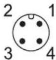 | 1: AS-i +2: AUX -3: AS-i -4: AUX + |
| AS-i OUT X22 | ||
| Connector M12 | ||
| Wiring |  | 1: AS-i +2: AUX -3: AS-i -4: AUX +5: - |
| Process connection IO-Link ports Class A X01...X04 | ||
| Connector M12 | ||
| Wiring |  | 1: +24 V DC (AUX)2: DI3: GND (AUX)4: C/Q IO-Link5: - |
13.2 AS-Interface
Content
Mapping: inputs and outputs of the IO-Link ports ....44
52002
13.2.1 Mapping: inputs and outputs of the IO-Link ports
Content
ID1 = 0x1 ....45
ID1 = 0x2 ....46
ID1 = 0x3 ....47
ID1 = 0x4 ....48
ID1 = 0x5 49
ID1 = 0x6 ....50
ID1 = 0x7 ....51
ID1 = 0x8 52
ID1 = 0x9 ....53
ID1 = 0xA....54
ID1 = 0xB....55
ID1 = 0xC....56
ID1 = 0xD....57
ID1 = 0xF ....58
Mapping: Status information....59
Mapping: PQI....60
52003
ID1 = 0x1
| Add. Slave (n+2)S-7.3.E, ID1=2 | Add. Slave (n+1)S-7.3.E, ID1=1 | Basic Slave (n)S-7.4.E | ||||||||||
| Channel 3 | Channel 2 | Channel 1 | Channel 0 | Channel 3 | Channel 2 | Channel 1 | Channel 0 | Channel 3 | Channel 2 | Channel 1 | Channel 0 | |
| Port X01 | 2 | 0 | → Mapping: Status information(→ p.59) | |||||||||
| Port X02 | 2 | 0 | ||||||||||
| Port X03 | 2 | 0 | ||||||||||
| Port X04 | 2 | 0 | ||||||||||
Legend:
n = 1...29 (valid address range of the Basic AS-i slave)
x = Word x of the process data at the input of the IO-Link port
52527
ID1 = 0x2
| Add. Slave (n+2)S-7.3.2, ID1=2 | Add. Slave (n+1)S-7.3.E, ID1=1 | Basic Slave (n)S-7.4.E | ||||||||||
| Channel 3 | Channel 2 | Channel 1 | Channel 0 | Channel 3 | Channel 2 | Channel 1 | Channel 0 | Channel 3 | Channel 2 | Channel 1 | Channel 0 | |
| Port X01 | 0 | → Mapping: Status information(→ p.59) | ||||||||||
| Port X02 | 0 | |||||||||||
| Port X03 | 0 | |||||||||||
| Port X04 3 2 | 1 0 0 | |||||||||||
Legend:
n = 1...29 (valid address range of the Basic AS-i slave)
x = Word x of the process data at the input of the IO-Link port
y = Word y of the process data at the output of the IO-Link port
52528
ID1 = 0x3
| Add. Slave (n+2)S-7.3.E, ID1=2 | Add. Slave (n+1)S-7.3.E, ID1=1 | Basic Slave (n)S-7.4.E | ||||||||||
| Channel 3 | Channel 2 | Channel 1 | Channel 0 | Channel 3 | Channel 2 | Channel 1 | Channel 0 | Channel 3 | Channel 2 | Channel 1 | Channel 0 | |
| Port X01 | 0 | → Mapping: Status information(→ p.59) | ||||||||||
| Port X02 | 0 | |||||||||||
| Port X03 | 0 | |||||||||||
| Port X04 3 2 1 | 0 | |||||||||||
Legend:
n = 1...29 (valid address range of the Basic AS-i slave)
x = Word x of the process data at the input of the IO-Link port
52529
ID1 = 0x4
52530
| Add. Slave (n+4)S-7.3.E, ID1=4 | Add. Slave (n+3)S-7.3.E, ID1=3 | Add. Slave (n+2)S-7.3.E, ID1=2 | Add. Slave (n+1)S-7.3.E, ID1=1 | Basic Slave (n)S-7.4.E | ||||||||||||||||
| Channel 3 | Channel 2 | Channel 1 | Channel 0 | Channel 3 | Channel 2 | Channel 1 | Channel 0 | Channel 3 | Channel 2 | Channel 1 | Channel 0 | Channel 3 | Channel 2 | Channel 1 | Channel 0 | Channel 3 | Channel 2 | Channel 1 | Channel 0 | |
| Port X01 | 15 | 14 | 13 | 12 | 11 | 10 | 9 | 8 | 7 | 6 | 5 | 4 | 3 | 2 | 1 | 0 | →Mapping: Status information(→p.59) | |||
| Port X02 | ||||||||||||||||||||
| Port X03 | ||||||||||||||||||||
| Port X04 | ||||||||||||||||||||
Legend:
n = 1...27 (valid address range of the Basic AS-i slave)
x = Word x of the process data at the input of the IO-Link port
ID1 = 0x5
52531
| Add. Slave (n+4)S-7.3.E, ID1=4 | Add. Slave (n+3)S-7.3.E, ID1=3 | Add. Slave (n+2)S-7.3.E, ID1=2 | Add. Slave (n+1)S-7.3.E, ID1=1 | Basic Slave (n)S-7.4.E | ||||||||||||||||
| Channel 3 | Channel 2 | Channel 1 | Channel 0 | Channel 3 | Channel 2 | Channel 1 | Channel 0 | Channel 3 | Channel 2 | Channel 1 | Channel 0 | Channel 3 | Channel 2 | Channel 1 | Channel 0 | Channel 3 | Channel 2 | Channel 1 | Channel 0 | |
| Port X01 | 7 | 6 5 | 4 3 | 2 1 0 | → Mapping: Status information(→ p.59) | |||||||||||||||
| Port X02 7 6 5 | 4 3 | 2 1 | 0 | |||||||||||||||||
| Port X03 | ||||||||||||||||||||
| Port X04 | ||||||||||||||||||||
Legend:
n = 1...27 (valid address range of the Basic AS-i slave)
x = Word x of the process data at the input of the IO-Link port
ID1 = 0x6
52532
| Add. Slave (n+4)S-7.3.E, ID1=4 | Add. Slave (n+3)S-7.3.E, ID1=3 | Add. Slave (n+2)S-7.3.E, ID1=2 | Add. Slave (n+1)S-7.3.E, ID1=1 | Basic Slave (n)S-7.4.E | |||||||||||||||
| Channel 3 | Channel 2 | Channel 1 | Channel 0 | Channel 3 | Channel 2 | Channel 1 | Channel 0 | Channel 3 | Channel 2 | Channel 1 | Channel 0 | Channel 3 | Channel 2 | Channel 1 | Channel 0 | Channel 3 | Channel 2 | Channel 1 | Channel 0 |
| Port X01 | 3 2 | 1 0 | → Mapping: Status information(→ p.59) | ||||||||||||||||
| Port X02 | 3 | 2 1 | 0 | ||||||||||||||||
| Port X03 | 3 2 | 1 0 | |||||||||||||||||
| Port X04 3 2 | 0 | ||||||||||||||||||
Legend:
n = 1...27 (valid address range of the Basic AS-i slave)
x = Word x of the process data at the input of the IO-Link port
ID1 = 0x7
52533
| Add. Slave (n+4)S-7.3.2, ID1=4 | Add. Slave (n+3)S-7.3.2, ID1=3 | Add. Slave (n+2)S-7.3.E, ID1=2 | Add. Slave (n+1)S-7.3.E, ID1=1 | Basic Slave (n)S-7.4.E | ||||||||||||||||
| Channel 3 | Channel 2 | Channel 1 | Channel 0 | Channel 3 | Channel 2 | Channel 1 | Channel 0 | Channel 3 | Channel 2 | Channel 1 | Channel 0 | Channel 3 | Channel 2 | Channel 1 | Channel 0 | Channel 3 | Channel 2 | Channel 1 | Channel 0 | |
| Port X01 | 1 0 | 1 0 | → Mapping: Status information(→ p.59) | |||||||||||||||||
| Port X02 | 1 0 | 1 0 | ||||||||||||||||||
| Port X03 1 | 0 | 1 0 | ||||||||||||||||||
| Port X04 1 0 | 1 0 | |||||||||||||||||||
Legend:
n = 1...27 (valid address range of the Basic AS-i slave)
x = Word x of the process data at the input of the IO-Link port
y = Word y of the process data at the output of the IO-Link port
ID1 = 0x8
| Add. Slave (n+3)S-7.3.2, ID1=3 | Add. Slave (n+2)S-7.3.2, ID1=2 | Add. Slave (n+1)S-7.3.E, ID1=1 | Basic Slave (n)S-7.4.E | |||||||||||||
| Channel 3 | Channel 2 | Channel 1 | Channel 0 | Channel 3 | Channel 2 | Channel 1 | Channel 0 | Channel 3 | Channel 2 | Channel 1 | Channel 0 | Channel 3 | Channel 2 | Channel 1 | Channel 0 | |
| Port X01 | 1 0 | 0 | → Mapping: Status information(→ p.59) | |||||||||||||
| Port X02 | 1 0 | 0 | ||||||||||||||
| Port X03 1 | 0 | 0 | ||||||||||||||
| Port X04 1 0 | 0 | |||||||||||||||
Legend:
n = 1...28 (valid address range of the Basic AS-i slave)
x = Word x of the process data at the input of the IO-Link port
y = Word y of the process data at the output of the IO-Link port
52534
ID1 = 0x9
| Add. Slave (n+3)S-7.3.2, ID1=3 | Add. Slave (n+2)S-7.3.E, ID1=2 | Add. Slave (n+1)S-7.3.E, ID1=1 | Basic Slave (n)S-7.4.E | |||||||||||||
| Channel 3 | Channel 2 | Channel 1 | Channel 0 | Channel 3 | Channel 2 | Channel 1 | Channel 0 | Channel 3 | Channel 2 | Channel 1 | Channel 0 | Channel 3 | Channel 2 | Channel 1 | Channel 0 | |
| Port X01 | 0 | 1 | 0 | → Mapping: Status information(→ p.59) | ||||||||||||
| Port X02 | 0 | 1 | 0 | |||||||||||||
| Port X03 | 0 | 1 | 0 | |||||||||||||
| Port X04 | 0 | 1 | 0 | |||||||||||||
Legend:
n = 1...28 (valid address range of the Basic AS-i slave)
x = Word x of the process data at the input of the IO-Link port
y = Word y of the process data at the output of the IO-Link port
52535
ID1 = 0xA
| Add. Slave (n+2)S-7.3.2, ID1=2 | Add. Slave (n+1)S-7.3.E, ID1=1 | Basic Slave (n)S-7.4.E | ||||||||||
| Channel 3 | Channel 2 | Channel 1 | Channel 0 | Channel 3 | Channel 2 | Channel 1 | Channel 0 | Channel 3 | Channel 2 | Channel 1 | Channel 0 | |
| Port X01 | 0 | 0 | → Mapping: Status information(→ p.59) | |||||||||
| Port X02 | 0 | 0 | ||||||||||
| Port X03 | 0 | 0 | ||||||||||
| Port X04 | 0 | 0 | ||||||||||
Legend:
n = 1...29 (valid address range of the Basic AS-i slave)
x = Word x of the process data at the input of the IO-Link port
y = Word y of the process data at the output of the IO-Link port
52536
ID1 = 0xB
| Add. Slave (n+1)S-7.3.2, ID1=1 | Basic Slave (n)S.-7.4.E | |||||||
| Port X01 | 0 | → Mapping:Status information(→ p.59) | ||||||
| Port X02 | 0 | |||||||
| Port X03 | 0 | |||||||
| Port X04 | 0 | |||||||
Legend:
n = 1...30 (valid address range of the Basic AS-i slave)
y = Word y of the process data at the output of the IO-Link port
52537
ID1 = 0xC
| Add. Slave (n+2)S-7.3.E, ID1=2 | Add. Slave (n+1)S-7.3.E, ID1=1 | Basic Slave (n)S-7.4.E | ||||||||||
| Channel 3 | Channel 2 | Channel 1 | Channel 0 | Channel 3 | Channel 2 | Channel 1 | Channel 0 | Channel 3 | Channel 2 | Channel 1 | Channel 0 | |
| Port X01 | 1 | 0 | → Mapping: Status information(→ p.59) | |||||||||
| Port X02 | 1 | 0 | ||||||||||
| Port X03 | 1 | 0 | ||||||||||
| Port X04 | 1 | 0 | ||||||||||
Legend:
n = 1...29 (valid address range of the Basic AS-i slave)
x = Word x of the process data at the input of the IO-Link port
52538
ID1 = 0xD
| Add. Slave (n+1)S-7.3.E, ID1=1 | Basic Slave (n)S-7.4.E | |||||||
| Channel 3 | Channel 2 | Channel 1 | Channel 0 | Channel 3 | Channel 2 | Channel 1 | Channel 0 | |
| Port X01 | 0 | → Mapping: Status information(→ p.59) | ||||||
| Port X02 | 0 | |||||||
| Port X03 | 0 | |||||||
| Port X04 | 0 | |||||||
Legend:
n = 1...30 (valid address range of the Basic AS-i slave)
x = Word x of the process data at the input of the IO-Link port
52539
ID1 = 0xF
| Basic Slave (n)S-7.4.E | ||||
| Channel 3 | Channel 2 | Channel 1 | Channel 0 | |
| Port X01 | 0 | |||
| Port X02 | 0 | |||
| Port X03 | 0 | |||
| Port X04 | 0 | |||
Legend:
n = 1...31 (valid address range of the Basic AS-i slave)
x = Word x of the process data at the input of the IO-Link port
52540
Mapping: Status information
| Bit | |||||||||||||||
| 15 | 14 | 13 | 12 | 11 | 10 | 9 | 8 | 7 | 6 | 5 | 4 | 3 | 2 | 1 | 0 |
| reserved | SC:X03orX04 | SC:X01orX02 | |||||||||||||
| Port X01: PQI | reserved | PCE | res. | CMDReq | CMDResp | ||||||||||
| Port X03: PQI Port X02: PQI | |||||||||||||||
| Number of Events in Buffer | Port X04: PQI | ||||||||||||||
| Legend:▪ SC Short Circuit: indicates whether there is a short circuiton at least one of the pair of IO-Link ports 1 bit 0x0 no short circuit0x1 short circuit | |||||||||||||||
| ▪ CMD Resp Command Response: indicates whether the acycliccommand channel (response) contains valid data andwhether it can be read 1 bit 0x0 not ready0x1 ready | |||||||||||||||
| ▪ CMD Req Command Request: indicates whether the acyclicrequest channel (request) is valid 1 bit 0x0 not valid0x1 Valid | |||||||||||||||
| ▪ PCE Port Configuration Error: indicates whether projectedvalues for "Vendor ID" and "Device ID" correspondwith the values of the IO-Link devices on the IO-Linkport 1 bit 0x0 no error0x1 error | |||||||||||||||
| ▪ PQI Port Qualifier Information: 1 byte → Mapping: PQI (→ p.60)▪ Number ofEvents inBuffer Number of events in the buffer memory 1 byte 0x00...0x0C | |||||||||||||||
Mapping: PQI
52019
| Bit | |||||||
| 7 6 5 4 | 3 2 1 0 | ||||||
| PQ | DE | DA | DACT | res. | res. | DI (Pin 2) | DI (Pin 4) |
| Legend: | |||||||
| DI (Pin 4) | Signal level of the digital input on pin 4 (if in use) | 1 bit | 0x0 | LOW | |||
| 0x1 | HIGH | ||||||
| DI (Pin 2) | Signal level of the digital input on pin 2 (DI) | 1 bit | 0x0 | LOW | |||
| 0x1 | HIGH | ||||||
| DACT | Device Deactivated: indicates whether IO-Link device has been deactivated via the port function | 1 bit | 0x0 | IO-Link device activated | |||
| 0x1 | IO-Link device deactivated | ||||||
| DA | Device Available: indicates whether an IO-Link device is available at the IO-Link port | 1 bit | 0x0 | no IO-Link device available | |||
| 0x1 | IO-Link device recognised and in the operating mode "Peroperate" or "Operate" | ||||||
| DE | Device Error: indicates occurring errors in the connected IO-Link device | 1 bit | 0x0 | no error | |||
| 0x1 | error or warning | ||||||
| PQ | Port Qualifier: indicates whether the input data / output data of the IO-Link device are valid | 1 bit | 0x0 | Data is invalid | |||
| 0x1 | Data is valid | ||||||
13.3 Command interface
Content
Structure of the command interface 61
Overview: Acyclic commands....64
0x01: Read IO-Link Port Configuration Errors....65
0x02: Write IO-Link Port Configuration....66
0x03: Read IO-Link Port Configuration 70
0x04: Read Input Process Data 73
0x05: Read Output Process Data....75
0x06: Write Output Process Data....77
0x07: Read Diagnosis Data....79
0x08: Factory Defaults....81
0x09: Set IO-Link Failsafe Data 82
0x0A: Write Parameter 84
0x0B: Read Parameter 87
0x0C: Read Device Name, Serial Number, HW and SW Revisions 89
0x0D: Update Firmware....91
52117
13.3.1 Structure of the command interface
52118
Via the command interface, the user can send acyclic commands from the AS-i master to the IO-Link master. An acyclic command consists of the following components:
- Command request (AS-i master >>> IO-Link master) (→ p. 62)
• Command response (IO-Link master >>> AS-i master) (→ p. 63)
Command request (AS-i master >>> IO-Link master)
52119
| Byte Contents | |
| 0 Block ID | |
| 1 Command ID | |
| 2 Target ID | |
| 3 Request Data Length | |
| 4...160 Request Data |
Legend:
| • [Block ID] | Fragmentation information for data transfer via several data blocks | 8 bits 0x00 | No fragmentation | |
| 0x01 | New command transmission started; this is the first segment | |||
| 0xFF | Last segment; after this data block, the command execution starts on IO-Link master | |||
| • [Command ID] | Command ID | 8 bits | →Overview: Acyclic commands(→p.64) | |
| • [Target ID] | ID of the target of the required operation | 8 bits | 0x01 | IO-Link port 1 |
| 0x02 | IO-Link port 2 | |||
| 0x03 | IO-Link port 3 | |||
| 0x04 | IO-Link port 4 | |||
| 0x0A | all IO-Link ports | |||
| • [Request Data Length] | Length of the request data in this fragment (number of bytes) | 8 bits 0x00 | 0 | |
| ... | ||||
| 0x9C | 156 | |||
| • [Request Data] | Request data (n bytes) | n*8 bits | per byte: 0x00...0xFF | |
Command response (IO-Link master >>> AS-i master)
52120
| Byte Contents |
| 0 Block ID |
| 1 Block Counter |
| 2 Command Status |
| 3 Response Data Length |
| 4...160 Response Data |
Legend:
| • [Block ID] | Fragmentation information for data transfer via several data blocks | 8 bits | 0x00 | No fragmentation |
| 0x01 | New command transmission started; this is the first Segment | |||
| 0xFF | Last segment; after this data block, the command execution starts on IO-Link master | |||
| • [Block Counter] | Counter for processed blocks; if the maximum value is reached, the counter is reset to 0x00 | 8 bits | 0x00...0xFF | |
| • [Command Status] | Processing / diagnostic status (command-specific) | 8 bits | 0x00...0x0B | |
| • [Response Data Length] | Length of the return data in this fragment (number of the bytes n) | 0x00 | 0 | |
| ... | ... | |||
| 0x9C | 156 | |||
| • [Response Data] | Return data (n bytes) | n*8 bits | per byte: 0x00...0xFF |
13.3.2 Overview: Acyclic commands
51972
| Command ID | Reference |
| 0x01 | → 0x01: Read IO-Link Port Configuration Errors (→ p. 65) |
| 0x02 | → 0x02: Write IO-Link Port Configuration (→ p. 66) |
| 0x03 | → 0x03: Read IO-Link Port Configuration (→ p. 70) |
| 0x04 | → 0x04: Read Input Process Data (→ p. 73) |
| 0x05 | → 0x05: Read Output Process Data (→ p. 75) |
| 0x06 | → 0x06: Write Output Process Data (→ p. 77) |
| 0x07 | → 0x07: Read Diagnosis Data (→ p. 79) |
| 0x08 | → 0x08: Factory Defaults (→ p. 81) |
| 0x09 | → 0x09: Set IO-Link Failsafe Data (→ p. 82) |
| 0x0A | → 0x0A: Write Parameter (→ p. 84) |
| 0x0B | → 0x0B: Read Parameter (→ p. 87) |
| 0x0C | → 0x0C: Read Device Name, Serial Number, HW and SW Revisions (→ p. 89) |
| 0x0D | → 0x0D: Update Firmware (→ p. 91) |
13.3.3 0x01: Read IO-Link Port Configuration Errors
52123
The command verifies whether the projected parameters "Vendor ID" and "Device ID" correspond with the parameter values of the connected IO-Link devices at the IO-Link ports X01...X04.
Command request
52124
| Byte Bit | ||||||||
| 7 6 5 4 3 2 1 0 | ||||||||
| 0 0x00 | ||||||||
| 1 0x01 | ||||||||
| 2 0x0A | ||||||||
| 3 0x00 | ||||||||
| 4...160 ignored | ||||||||
Command response
52126
| Byte Bit | ||||||||
| 7 6 5 | 4 3 2 1 0 | |||||||
| 0 0x00 | ||||||||
| 1 Block Counter | ||||||||
| 2 | Command status (→ list "Diagnostic codes") | |||||||
| 3 0x01 | ||||||||
| 4 reserved Port X04: | PCE | Port X03: PCE | Port X02: PCE | Port X01: PCE | ||||
| 5...160 ignored | ||||||||
Legend:
- [Port X0n: PCE]
Port Configuration Error (PCE) - indicates whether projected values for "Vendor ID" and "Device ID" correspond with the values of the IO-Link devices at the IO-Link port
1 bit
0x0
OK
0x1
Error
Diagnostic codes:
0x01 OK
- 0x04 Blocked Port - another acyclic access is still active
- 0x07 Wrong Target ID (wrong Port number)
- 0x08 Invalid length (wrong input parameter length)
■ 0x0A Wrong Block ID
13.3.4 0x02: Write IO-Link Port Configuration
52127
The command writes the configuration of the IO-Link ports X01...X04 of the IO-Link master. The configuration consists of the following parameters:
- Port Mode
- Validation ID / Data Storage
- Vendor ID
- Device ID
- Failsafe Mode
- Failsafe Value Pin 4 (DO)
Command request
52128
| Byte Bit | ||||||||
| 7 6 5 4 3 2 1 0 | ||||||||
| 0 0x00 | ||||||||
| 1 0x02 | ||||||||
| 2 0x0A | ||||||||
| 3 0x28 | ||||||||
| 4 Port X01: Port Mode | ||||||||
| 5 Port X01: Master Cycle Time | ||||||||
| 6 Port X01: Validation ID | ||||||||
| 7 Port X01: Vendor ID (MSB) | ||||||||
| 8 Port X01: Vendor ID (LSB) | ||||||||
| 9 Port X01: Device ID (MSB) | ||||||||
| 10 Port X01: Device ID | ||||||||
| 11 Port X01: Device ID (LSB) | ||||||||
| 12 | Port X01: Failsafe Mode - IO-Link | |||||||
| 13 | Port X01: Failsafe Value - Pin 4 (DO) | |||||||
| 14...23 | Port X02: Port configuration ( row 4...13) | |||||||
| 24...33 | Port X03: Port configuration ( row 4...13) | |||||||
| 34...43 | Port X04: Port configuration ( row 4...13) | |||||||
| 44...160 | ignored | |||||||
Legend:
| [Port Mode] | Operating mode of the IO-Link port | 1 byte | 0x00 | deactivated |
| 0x01 | digital input (DI) | |||
| 0x02 | digital output (DO) | |||
| 0x03 | IO-Link | |||
| [Master Cycle Time] | Cycle time of the data transmission between the IO-Link master and the IO-Link device | 1 byte | 0x00 | As fast as possible |
| 0x01 | 2 milliseconds | |||
| 0x02 | 4 milliseconds | |||
| 0x03 | 8 milliseconds | |||
| 0x04 | 16 milliseconds | |||
| 0x05 | 32 milliseconds | |||
| 0x06 | 64 milliseconds | |||
| 0x07 | 128 milliseconds | |||
| [Validation ID] | Supported IO-Link standard and behaviour of the IO-Link master when connecting new IO-Link devices to the IO-Link port | 1 byte | 0x00 | no validation |
| 0x01 | V1.0 device | |||
| 0x02 | V1.1 device | |||
| 0x03 | V1.1 device with Backup + Restore | |||
| 0x04 | V1.1 device with Restore |
| ▪ [Vendor ID] | Vendor ID of the manufacturer of the device on the IO-Link portVendor ID = 0x1234▪ Vendor ID (MSB) = 0x12▪ Vendor ID (LSB) = 0x34 | 2 bytes per byte: 0x00...0xFF |
| ▪ [Device ID] | Device ID of the device on the IO-Link portDevice ID = 0x123456▪ Device ID (MSB) = 0x12▪ Device ID = 0x34▪ Device ID (LSB) = 0x56 | 3 bytes per byte: 0x00...0xFF |
| ▪ [Failsafe Mode -- IO-Link] | Fail-safe mode for output data when the AS-Interface connection is interrupted | 1 byte 0x00 No Failsafe0x01 Failsafe Reset Value0x02 Failsafe Old Value0x03 Failsafe with Pattern |
| ▪ [Failsafe Mode -- Pin 4 (DO)] | Fail-safe value for the operating mode "digital output (DO) | 1 byte 0x00 Failsafe Reset Value0x01 Failsafe Old Value0x02 Failsafe Set Value |
Command response
| Byte Bit | ||||||||
| 7 6 5 4 3 2 1 0 | ||||||||
| 0 0x00 | ||||||||
| 1 Block Counter | ||||||||
| 2 | Command status (→ list "Diagnostic codes") | |||||||
| 3 0x00 | ||||||||
| 4...160 ignored | ||||||||
Diagnostic codes:
0x01 OK
- 0x04 Blocked Port - another acyclic access is still active
- 0x07 Wrong Target ID (wrong Port number)
- 0x08 Invalid length (wrong input parameter length)
- 0x09 Wrong parameter (value of a parameter not in proper range)
- 0x0A Wrong Block ID
13.3.5 0x03: Read IO-Link Port Configuration
52130
The command reads the current configuration of the IO-Link ports X01...X04 of the IO-Link master.
The configuration consists of the following parameters:
- Port Mode
- Validation ID / Data Storage
- Vendor ID
- Device ID
- Failsafe Mode
- Failsafe Value Pin 4 (DO)
Command request
52131
| Byte Bit | ||||||||
| 7 6 5 4 3 2 1 0 | ||||||||
| 0 0x00 | ||||||||
| 1 0x03 | ||||||||
| 2 0x0A | ||||||||
| 3 0x00 | ||||||||
| 4...160 ignored | ||||||||
Command response
52132
| Byte Bit | ||||||||
| 7 6 5 4 3 2 1 0 | ||||||||
| 0 0x00 | ||||||||
| 1 Block Counter | ||||||||
| 2 | Command status (→ list "Diagnostic codes") | |||||||
| 3 0x28 | ||||||||
| 4 Port X01: Port Mode | ||||||||
| 5 Port X01: Master Cycle Time | ||||||||
| 6 Port X01: Validation ID | ||||||||
| 7 Port X01: Vendor ID (MSB) | ||||||||
| 8 Port X01: Vendor ID (LSB) | ||||||||
| 9 Port X01: Device ID (MSB) | ||||||||
| 10 Port X01: Device ID | ||||||||
| 11 | Port X01: Device ID (LSB) | |||||||
| 12 | Port X01: Failsafe Mode - IO-Link | |||||||
| 13 | Port X01: Failsafe Value - Pin 4 (DO) | |||||||
| 14...23 | Port X02: Port configuration (→ row 4...13) | |||||||
| 24...33 | Port X03: Port configuration (→ row 4...13) | |||||||
| 34...43 | Port X04: Port configuration (→ row 4...13) | |||||||
| 44...160 | ignored | |||||||
Legend:
| [Port Mode] | Operating mode of the IO-Link port | 1 byte | 0x00 | deactivated |
| 0x01 | digital input (DI) | |||
| 0x02 | digital output (DO) | |||
| 0x03 | IO-Link | |||
| [Master Cycle Time] | Cycle time of the data transmission between the IO-Link master and the IO-Link device | 1 byte | 0x00 | As fast as possible |
| 0x01 | 2 milliseconds | |||
| 0x02 | 4 milliseconds | |||
| 0x03 | 8 milliseconds | |||
| 0x04 | 16 milliseconds | |||
| 0x05 | 32 milliseconds | |||
| 0x06 | 64 milliseconds | |||
| 0x07 | 128 milliseconds | |||
| [Validation ID] | Supported IO-Link standard and behaviour of the IO-Link master when connecting new IO-Link devices to the IO-Link port | 1 byte | 0x00 | no validation |
| 0x01 | V1.0 device | |||
| 0x02 | V1.1 device | |||
| 0x03 | V1.1 device with Backup + Restore | |||
| 0x04 | V1.1 device with Restore |
| ▪ [Vendor ID] | Vendor ID of the manufacturer of the device on the IO-Link portVendor ID = 0x1234▪ Vendor ID (MSB) = 0x12▪ Vendor ID (LSB) = 0x34 | 2 bytes per byte: 0x00...0xFF |
| ▪ [Device ID] | Device ID of the device on the IO-Link portDevice ID = 0x123456▪ Device ID (MSB) = 0x12▪ Device ID = 0x34▪ Device ID (LSB) = 0x56 | 3 bytes per byte: 0x00...0xFF |
| ▪ [Failsafe Mode -- IO-Link] | Fail-safe mode for output data when the AS-Interface connection is interrupted | 1 byte 0x00 No Failsafe0x01 Failsafe Reset Value0x02 Failsafe Old Value0x03 Failsafe with Pattern |
| ▪ [Failsafe Mode -- Pin 4 (DO)] | Fail-safe value for the operating mode "digital output (DO) | 1 byte 0x00 Failsafe Reset Value0x01 Failsafe Old Value0x02 Failsafe Set Value |
Diagnostic codes:
- 0x01 OK
- 0x04 Blocked Port - another acyclic access is still active
- 0x07 Wrong Target ID (wrong Port number)
- 0x08 Invalid length (wrong input parameter length)
- 0x0A Wrong Block ID
13.3.6 0x04: Read Input Process Data
52133
The command reads the process data of the inputs of an IO-Link port of the IO-Link master and the corresponding status information (PQI).
Command request
| Byte Bit | ||||||||
| 7 6 5 4 3 2 1 0 | ||||||||
| 0 0x00 | ||||||||
| 1 0x04 | ||||||||
| 2 Target ID | ||||||||
| 3 0x00 | ||||||||
| 4...160 ignored | ||||||||
Legend:
- [Target ID]
Target of the required operation
8 bits
0x01
IO-Link port 1
0x02 IO-Link port 2
0x03 IO-Link port 3
0x04 IO-Link port 4
Command response
52135
| Byte Bit | ||||||||
| 7 6 5 4 3 2 1 0 | ||||||||
| 0 0x00 | ||||||||
| 1 Block Counter | ||||||||
| 2 | Command status (→ list "Diagnostic codes") | |||||||
| 3 Response Data Length | ||||||||
| 4 | PQ | DE | DA | DACT | res. | res. | DI (Pin2) | DI (Pin 4) |
| 5 | Input data (byte 1) | |||||||
| ... | ... | |||||||
| 5+(n-1) | Input data (byte n) | |||||||
| (5+n)...160 | ignored | |||||||
Legend:
| [Response Data Length] | Length of the return data (number of bytes n) | 8 bits | 0x03 | 3 bytes (n=2) |
| 0x05 | 5 bytes (n=4) | |||
| 0x09 | 9 bytes (n=8) | |||
| 0x11 | 17 bytes (n=16) | |||
| 0x21 | 33 bytes (n=32) | |||
| [PQ] | Port Qualifier: indicates the validity of the input/output data of the IO-Link device | 1 bit | 0x0 | data invalid |
| 0x1 | data valid | |||
| [DE] | Device Error: shows if an error or a warning has occurred; Note: The user needs to determine the cause of the fault separately via acyclic services. | 1 bit | 0x0 | no error |
| 0x1 | error | |||
| [DA] | Device Available: shows if the IO-Link device has been recognised and if the device is in the "preoperate" or in the "operate" state | 1 bit | 0x0 | no device |
| 0x1 | device detected | |||
| [DACT] | Device Deactivated: shows if the IO-Link port is configured and can be used | 1 bit | 0x0 | device activated |
| 0x1 | device deactivated | |||
| [DI (Pin 2)] | Signal level of the input data at pin 2 (if in use) | 1 bit | 0x0 | LOW |
| 0x1 | HIGH | |||
| [DI (Pin 4)] | Signal level of the input data at pin 4 (DI) | 1 bit | 0x0 | LOW |
| 0x1 | HIGH | |||
| [Input Data (Byte m)] | IO-Link input data (m = 1...n) | n*8 bits | per byte: 0x00...0xFF | |
Diagnostic codes:
0x01 OK
- 0x04 Blocked Port - another acyclic access is still active
- 0x07 Wrong Target ID (wrong Port number)
- 0x08 Invalid length (wrong input parameter length)
- 0x0A Wrong Block ID
13.3.7 0x05: Read Output Process Data
52136
The command reads the process data of the outputs of an IO-Link port of the IO-Link master.
Command request
52137
| Byte Bit | ||||||||
| 7 6 5 4 3 2 1 0 | ||||||||
| 0 0x00 | ||||||||
| 1 0x05 | ||||||||
| 2 Target ID | ||||||||
| 3 0x00 | ||||||||
| 4...160 ignored | ||||||||
Legend:
■ [Target ID] Target of the required operation
8 bits 0x01 IO-Link port 1
0x02 IO-Link port 2
0x03 IO-Link port 3
0x04 IO-Link port 4
Command response
52138
| Byte Bit | ||||||||
| 7 6 5 4 3 2 1 0 | ||||||||
| 0 0x00 | ||||||||
| 1 Block Counter | ||||||||
| 2 | Command status (→ list "Diagnostic codes") | |||||||
| 3 Response data length (number of bytes m) | ||||||||
| 4 Output acyclic process data switch (OPDS) | ||||||||
| 5 Output Data (Byte 1) | ||||||||
| ... ... | ||||||||
| 5+(n-1) Output Data (Byte n) | ||||||||
| (5+n)...160 | ignored | |||||||
Legend:
| [Response Data Length] | Length of the return data incl. OPDS byte (number of bytes n) | 8 bits | 0x03 | 3 bytes (n=2) |
| 0x05 | 5 bytes (n=4) | |||
| 0x09 | 9 bytes (n=8) | |||
| 0x11 | 17 bytes (n=16) | |||
| 0x21 | 33 bytes (n=32) | |||
| [OPDS] | Output acyclic data Switch: signals whether cyclic or acyclic process data is transmitted | 8 bits | 0x00 | cyclic process data |
| 0x01 | acyclic process data | |||
| [Output Data (Byte m)] | IO-Link output data (m = 1...n) | n*8 bits | per byte: 0x00...0xFF | |
Diagnostic codes:
0x01 OK
- 0x04 Blocked Port - another acyclic access is still active
- 0x07 Wrong Target ID (wrong Port number)
- 0x08 Invalid length (wrong input parameter length)
- 0x0A Wrong Block ID
13.3.8 0x06: Write Output Process Data
52139
The command writes the process data of the outputs of an IO-Link port of the IO-Link master.

If the flag [OPDS] is set to 0x01, then the cyclic output of process data is blocked. The output remains blocked until [OPDS] is set to 0x00.
Command request
52140
| Byte Bit | ||||||||
| 7 6 5 4 3 2 1 0 | ||||||||
| 0 0x00 | ||||||||
| 1 0x06 | ||||||||
| 2 Target ID | ||||||||
| 3 Output Data Length | ||||||||
| 4 Output acyclic process data switch (OPDS) | ||||||||
| 5 Output Data (Byte 1) | ||||||||
| ... ... | ||||||||
| 5+(n-1) | Output Data (Byte n) | |||||||
| (5+n)...160 | ignored | |||||||
Legend:
| • [Target ID] | ID of the target of the required operation | 8 bits | 0x01 | IO-Link port 1 |
| 0x02 | IO-Link port 2 | |||
| 0x03 | IO-Link port 3 | |||
| 0x04 | IO-Link port 4 | |||
| • [Output Data Length] | Length of the output data incl. OPDS byte (number of bytes) | 8 bits | 0x03 | 3 bytes (n=2) |
| 0x05 | 5 bytes (n=4) | |||
| 0x09 | 9 bytes (n=8) | |||
| 0x11 | 17 bytes (n=16) | |||
| 0x21 | 33 bytes (n=32) | |||
| • [OPDS] | Output acyclic data switch: signals whether cyclic or acyclic process data is transmitted | 8 bits | 0x00 | cyclic process data |
| 0x01 | acyclic process data | |||
| • [Output Data (Byte m)] | IO-Link output data (m = 1...n) | n*8 bits | per byte: 0x00...0xFF | |
Command response
| Byte Bit | ||||||||
| 7 6 5 4 3 2 1 0 | ||||||||
| 0 0x00 | ||||||||
| 1 Block Counter | ||||||||
| 2 | Command status (→ list "Diagnostic codes") | |||||||
| 3 0x00 | ||||||||
| 4...160 ignored | ||||||||
Diagnostic codes:
0x01 OK
- 0x04 Blocked Port - another acyclic access is still active
- 0x07 Wrong Target ID (wrong Port number)
- 0x08 Invalid length (wrong input parameter length)
- 0x09 Wrong parameter (value of a parameter not in proper range)
- 0x0A Wrong Block ID
13.3.9 0x07: Read Diagnosis Data
52142
The command reads the diagnostic information / events) of the IO-Link devices. The diagnostic information is stored in a ring buffer in the IO-Link master. The ring buffer stores a maximum of 12 events. If all memory locations of the ring buffer are occupied, the IO-Link master overwrites the oldest event with new incoming diagnostic information.
The ring buffer has a protection against the case that an IO-Link device reports the same error several times in a row. Only one message is stored for the same error.
Command request
52143
| Byte Bit | ||||||||
| 7 6 5 4 3 2 1 0 | ||||||||
| 0 0x00 | ||||||||
| 1 0x07 | ||||||||
| 2 0x0A | ||||||||
| 3 0x00 | ||||||||
| 4...160 ignored | ||||||||
Command response
52144
| Byte Bit | ||||||||
| 7 6 5 | 4 3 2 1 0 | |||||||
| 0 0x00 | ||||||||
| 1 Block Counter | ||||||||
| 2 | Command status (→ list "Diagnostic codes") | |||||||
| 3 0x05 | ||||||||
| 4 IO-Link port | ||||||||
| 5 Mode | ||||||||
| 6 Type | ||||||||
| 7 Event Code (MSB) | ||||||||
| 8 Event Code (LSB) | ||||||||
| 9...160 ignored | ||||||||
Legend:
| [IO-Link port] | IO-Link port | 8 bits | 0x01 | IO-Link port 1 |
| 0x02 | IO-Link port 2 | |||
| 0x03 | IO-Link port 3 | |||
| 0x04 | IO-Link port 4 | |||
| [Mode] | Occurrence of the error that has triggered the event | 8 bits | 0x40 | Individual message or warning |
| 0x80 | Error or warning has appeared | |||
| 0xC0 | Error or warning has disappeared | |||
| [Type] | Type of error that has triggered the event | 8 bits | 0x10 | Message |
| 0x20 | Warning | |||
| 0x30 | Error | |||
| [Event Code] Error cause | 16 bits | per byte: 0x00...0xFF | ||
| depends on the IO-Link device(→ IODD of the IO-Link devices) | ||||
Diagnostic codes:
0x01 OK
- 0x04 Blocked Port - another acyclic access is still active
- 0x05 Command Error, no response data available
- 0x07 Wrong Target ID (wrong Port number)
- 0x08 Invalid length (wrong input parameter length)
- 0x0A Wrong Block ID
13.3.10 0x08: Factory Defaults
52145
The command resets the configuration of the IO-Link ports of the IO-Link master to the factory settings. The bytes 4...8 contain the "reset" string in hexadecimal representation.
Command request
52146
| Byte Bit | ||||||||
| 7 6 5 | 4 3 2 1 0 | |||||||
| 0 0x00 | ||||||||
| 1 0x08 | ||||||||
| 2 0x0A | ||||||||
| 3 0x05 | ||||||||
| 4 0x72 | ||||||||
| 5 0x65 | ||||||||
| 6 0x73 | ||||||||
| 7 0x65 | ||||||||
| 8 0x74 | ||||||||
| 9...160 ignored | ||||||||
Command response
52147
| Byte Bit | ||||||||
| 7 6 5 | 4 3 2 1 0 | |||||||
| 0 0x00 | ||||||||
| 1 Block Counter | ||||||||
| 2 | Command status (→ list "Diagnostic codes") | |||||||
| 3 0x00 | ||||||||
| 4...160 ignored | ||||||||
Diagnostic codes:
- 0x04 Blocked Port - another acyclic access is still active
- 0x07 Wrong Target ID (wrong Port number)
- 0x08 Invalid length (wrong input parameter length)
- 0x09 Wrong parameter (value of a parameter not in proper range)
- 0x0A Wrong Block ID
13.3.11 0x09: Set IO-Link Failsafe Data
52148
The command writes the fail-safe value of the output of an IO-Link port of the IO-Link master ("IO-Link" operating mode).
Command request
52149
| Byte Bit | ||||||||
| 7 6 5 4 3 2 1 0 | ||||||||
| 0 0x00 | ||||||||
| 1 0x09 | ||||||||
| 2 Target ID | ||||||||
| 3 Failsafe Data Length | ||||||||
| 4 Failsafe Data (Byte 1) | ||||||||
| ... ... | ||||||||
| 4+(n-1) Failsafe Data (Byte n) | ||||||||
| (4+n)...160 | ignored | |||||||
Legend:
| • [Target ID] | Target of the required operation | 8 bits | 0x01 | IO-Link port 1 |
| 0x02 | IO-Link port 2 | |||
| 0x03 | IO-Link port 3 | |||
| 0x04 | IO-Link port 4 | |||
| • [Failsafe Data Length] | Length of the fail-safe value date (number of bytes) | 1 Byte | 0x01 | 1 byte |
| ... | ... | |||
| 0x20 | 32 bytes | |||
| • [Failsafe Data (Byte m)] | IO-Link fail-safe values (m = 1...n) | n*8 bits | per byte: 0x00...0xFF | |
Command response
| Byte Bit | ||||||||
| 7 6 5 4 3 2 1 0 | ||||||||
| 0 0x00 | ||||||||
| 1 Block Counter | ||||||||
| 2 | Command status (→ list "Diagnostic codes") | |||||||
| 3 0x00 | ||||||||
| 4...160 ignored | ||||||||
Diagnostic codes:
- 0x01 OK
- 0x04 Blocked Port - another acyclic access is still active
- 0x07 Wrong Target ID (wrong Port number)
- 0x08 Invalid length (wrong input parameter length)
- 0x0A Wrong Block ID
13.3.12 0x0A: Write Parameter
52151
The command writes the parameter on an IO-Link device connected to the IO-Link master.
Parameters with a length <= 150 bytes are transferred with an acyclic write command (block ID = 0x00).
Parameters with a length > 150 bytes are transferred with 2 acyclic write commands.
- Command: Write first segment of the parameter
■ Block ID: 0x01
■ Data Length: 154 bytes
- Parameter Data Length: Length n of the parameter (150 bytes < n < 233 bytes)
■ Parameter Data: Bytes 0...149
- Command: Write second segment of the parameter
■ Block ID: 0xFF
- Data Length: Number m of the remaining bytes of the parameter data (m = n -150)
The fields Index, Subindex, Parameter Data Length contain the parameter data: Bytes 150...n

The total of the values in the fields Data Length of the first and second command is the length of the parameter.
Command request
| Byte Bit | ||||||||
| 7 6 5 4 3 2 1 0 | ||||||||
| 0 Block ID | ||||||||
| 1 0x0A | ||||||||
| 2 Target ID | ||||||||
| 3 Data Length | ||||||||
| 4 Index (LSB) | ||||||||
| 5 Index (MSB) | ||||||||
| 6 Subindex | ||||||||
| 7 Parameter Data Length (n Bytes) | ||||||||
| 8 Parameter Data (Byte 1) | ||||||||
| ... ... | ||||||||
| 8+(n-1) Parameter Data (Byte n) | ||||||||
| (8+n)...160 | ignored | |||||||
Legend:
| • [Target ID] | Target of the required operation | 8 bits | 0x01 | IO-Link port 1 |
| 0x02 | IO-Link port 2 | |||
| 0x03 | IO-Link port 3 | |||
| 0x04 | IO-Link port 4 | |||
| • [Data Length] | Length of the request data in this segment (number of bytes) | 8 bits | 0x00 | 0 |
| ... | ||||
| 0x9C | 156 | |||
| • [Index] | Index of the IO-Link object Index = 0x1234 | 16 bits | per byte: 0x00...0xFF | |
| • Index (MSB) = 0x12 | ||||
| • Index (LSB) = 0x34 | ||||
| • [Subindex] | Sub-index of the IO-Link object | 8 bits | 0x00...0xFF | |
| • [Parameter Data Length] | Length of the parameter data (number of bytes n) | 8 bits | 0x00 | 0 bytes |
| ... | ... | |||
| 0xE8 | 232 bytes | |||
| • [Parameter Data (Byte m)] | Parameter data (m = 1...n) | m*8 bits | per byte: 0x00...0xFF | |
Command response
52153
| Byte Bit | ||||||||
| 7 6 5 4 3 2 1 0 | ||||||||
| 0 0x00 | ||||||||
| 1 Block Counter | ||||||||
| 2 | Command status (→ list "Diagnostic codes") | |||||||
| 3 Data Length | ||||||||
| 4 ignored / Error Code | ||||||||
| 5 ignored / Additional Error Code | ||||||||
| 6...160 ignored | ||||||||
Legend:
- [Data Length]
Length of the return data (number of bytes n)
8 bits
0x00
no error codes
0x02
Error code and additional error code
- [Error Code]
Error code
8 bits
0x80
Error in IO-Link device
■ [Additional Error Code]
additional error code
8 bits
→ IODD of the IO-Link device
Diagnostic codes:
0x01 OK
- 0x04 Blocked Port - another acyclic access is still active
- 0x07 Wrong Target ID (wrong Port number)
- 0x08 Invalid length (wrong input parameter length)
- 0x0A Wrong Block ID
- 0x0B Error - for additional information see data field
13.3.13 0x0B: Read Parameter
52154
The command reads the parameter of an IO-Link device connected to the IO-Link master. The parameter can be accessed via index and sub-index of the corresponding IO-Link object.
Parameters that are longer than 150 bytes are read with 2 acyclic commands.
- Command: Read first segment of the parameter value
■ Block ID: 0x01
■ Parameter Data Length: 150 bytes
■ Parameter Data: Bytes 0...149
- Command: Read second segment of the parameter value
■ Block ID: 0xFF
- Parameter Data Length: Number m of the remaining bytes (m = n - 150)
- Parameter Data: Bytes 150...n (n = length of the parameter)
Command request
52155
| Byte Bit | ||||||||
| 7 6 5 4 3 2 1 0 | ||||||||
| 0 0x00 | ||||||||
| 1 0x0B | ||||||||
| 2 Target ID | ||||||||
| 3 0x03 | ||||||||
| 4 Index (LSB) | ||||||||
| 5 Index (MSB) | ||||||||
| 6 Subindex | ||||||||
| 7...160 | ignored | |||||||
Legend:
| • [Target ID] | Target of the required operation | 8 bits | 0x01 | IO-Link port 1 |
| 0x02 | IO-Link port 2 | |||
| 0x03 | IO-Link port 3 | |||
| 0x04 | IO-Link port 4 | |||
| • [Index] | Index des IO-Link ObjektsIndex = 0x1234 | 16 bits | per byte: 0x00...0xFF | |
| • Index (MSB) = 0x12 | ||||
| • Index (LSB) = 0x34 | ||||
| • [Subindex] | Sub-index of the IO-Link object | 8 bits | 0x00...0xFF | |
Command response
52156
| Byte Bit | ||||||||
| 7 6 5 | 4 3 2 1 0 | |||||||
| 0 Block-ID | ||||||||
| 1 Block Counter | ||||||||
| 2 | Command status (→ list "Diagnostic codes") | |||||||
| 3 Parameter Data Length (n Bytes) | ||||||||
| 4 Parameter Data (Byte 1) | ||||||||
| ... ... | ||||||||
| 4+(n-1) Parameter Data (Byte n) | ||||||||
| (4+n)...160 | ignored | |||||||
Legend:
- [Parameter Data Length]
Length of the return data (number of bytes n)
8 bits 0x00 0 bytes
...
0x9C 156 bytes - [Parameter Data (Byte m)]
Parameter-Daten (m = 1...n)
n*8 bits per byte: 0x00...0xFF
Diagnostic codes:
0x01 OK
- 0x04 Blocked Port - another acyclic access is still active
- 0x07 Wrong Target ID (wrong Port number)
- 0x08 Invalid length (wrong input parameter length)
- 0x0A Wrong Block ID
- 0x0B Error - for additional information see data field
13.3.14 0x0C: Read Device Name, Serial Number, HW and SW Revisions
52157
The command reads the following parameters of the IO-Link master:
- Device Name
- Serial number
- Hardware revision
• AS-i CPU - software revision - IOL CPU - software revision
Command request
52158
| Byte Bit | ||||||||
| 7 6 5 4 3 2 1 0 | ||||||||
| 0 0x00 | ||||||||
| 1 0x0C | ||||||||
| 2 0x0A | ||||||||
| 3 0x00 | ||||||||
| 4...160 ignored | ||||||||
Command response
52159
| Byte Bit | ||||||||
| 7 6 5 4 3 2 1 0 | ||||||||
| 0 0x00 | ||||||||
| 1 Block Counter | ||||||||
| 2 | Command status (→ list "Diagnostic codes") | |||||||
| 3 0x32 | ||||||||
| 0...5 Device Name | ||||||||
| 6 0x20 | ||||||||
| 7...18 Serial Number | ||||||||
| 19 0x20 | ||||||||
| 20...21 Hardware revision | ||||||||
| 22 0x20 | ||||||||
| 23...35 | AS-i CPU - software revision | |||||||
| 36 0x20 | ||||||||
| 37...49 | IOL CPU - software revision | |||||||
| 50...160 ignored | ||||||||
Legend:
| ■ [Device Name] | Device name (ASCII coded) | 48 bits | per byte: 0x00...0xFF |
| ■ [Serial Number] | Serial number (ASCII coded) | 96 bits | per byte: 0x00...0xFF |
| ■ [Hardware revision] | Hardware revision (ASCII coded) | 16 bits | per byte: 0x00...0xFF |
| ■ [AS-i CPU - software revision] | AS-i CPU software revision (ASCII coded) | 104 bits | per byte: 0x00...0xFF |
| ■ [IOL CPU software revision] | IOL CPU - software revision (ASCII coded) | 104 bits | per byte: 0x00...0xFF |
Diagnostic codes:
0x01 OK
- 0x04 Blocked Port - another acyclic access is still active
- 0x07 Wrong Target ID (wrong Port number)
- 0x08 Invalid length (wrong input parameter length)
- 0x0A Wrong Block ID
13.3.15 0x0D: Update Firmware
52160
The command updates the firmware of the IO-Link masters via the AS-i network. The bytes 4...9 contain the "update" string in hexadecimal representation.
Carry out the following steps in the correct sequence:

▶ During the firmware update, disconnect all IO-Link devices from the IO-Link master to avoid unexpected behaviour (deactivate ports).
The command uses 1 AS-i input slave and 4 AS-i output slaves for the data transmission. The valid address range for the basic AS-i slave of the AC6000 is restricted to 1...27.
▶ Ensure that 5 connected AS-i addresses are available for the update process.
▶ Select and set the valid address for the basic AS-i slave of the AC6000.
▶ Ensure that the PLC application does not write any data to the AS-i outputs during the update process.

ifm recommends using the function block "_FWUpdate" of the library ifm_AC600x_Lib for CODESYS for the firmware update.
- Deactivate all IO-Link ports of the AC6000 ( 0x02: Write IO-Link Port Configuration ( p. 66)
- For AS-i master, activate the Projection Mode.
- Allow PLC access to the AS-i outputs (Output Access)
- Execute the command "0x0D: Updating Firmware".
- After the update, disconnect the device from power and reconnect it.
The boot loader verifies the CRC sum and container version of the firmware file.
If the update has been successful, each channel of the AS-i input slaves indicates the value 0x01.
Command request
| Byte Bit | ||||||||
| 7 6 5 4 3 2 1 0 | ||||||||
| 0 0x00 | ||||||||
| 1 0x0D | ||||||||
| 2 0x0A | ||||||||
| 3 0x08 | ||||||||
| 4 0x75 | ||||||||
| 5 0x70 | ||||||||
| 6 0x64 | ||||||||
| 7 0x61 | ||||||||
| 8 0x74 | ||||||||
| 9 0x65 | ||||||||
| 10 File Size (LSB) | ||||||||
| 11 File Size (MSB) | ||||||||
| 12...160 ignored | ||||||||
Legend:
- [File Size]
Size of the ifm firmware file in bytes divided by 4 (rounded up value) 16 bits per byte: 0x00...0xFF
The IO-Link master calculates the start address in the flash memory from this valuer
Size = 0x1234
- Size (MSB) = 0x12
■ Size (LSB) = 0x34
Command response
52162
| Byte Bit | |||||||||
| 7 6 5 4 3 2 1 0 | |||||||||
| 0 0x00 | |||||||||
| 1 Block Counter | |||||||||
| 2 | Command status (→ list "Diagnostic codes") | ||||||||
| 3 0x00 | |||||||||
| 4...160 | ignored | ||||||||
Diagnostic codes:
- 0x04 Blocked Port - another acyclic access is still active
- 0x07 Wrong Target ID (wrong Port number)
- 0x08 Invalid length (wrong input parameter length)
- 0x09 Wrong parameter (value of a parameter not in proper range)
- 0x0A Wrong Block ID
14 Index
0
0x01 Read IO-Link Port Configuration Errors....65
0x02 Write IO-Link Port Configuration....66
0x03 Read IO-Link Port Configuration....70
0x04 Read Input Process Data....73
0x05 Read Output Process Data 75
0x06 Write Output Process Data 77
0x07 Read Diagnosis Data....79
0x08 Factory Defaults 81
0x09 Set IO-Link Failsafe Data 82
0x0A Write Parameter 84
0x0B Read Parameter....87
0x0C Read Device Name, Serial Number, HW and SW Revisions....89
0x0D Update Firmware....91
A
Accessories 37
Addressing the AS-i slave of the AC6000....24
Addressing via AS-i master 24
Addressing with addressing unit....25
Adjusting the gateway profile....26
Appendix....38
Application 39
Approvals / Tests....41
AS-i classification....41
AS-interface....9
AS-Interface....43
C
Cleaning process....35
Command interface 61
Command request .....65, 67, 70, 73, 75, 77, 79, 81, 82, 85, 87, 89, 92
Command request (AS-i master >>> IO-Link master) 62
Command response .....65, 69, 71, 74, 76, 78, 80, 81, 83, 86, 88, 90, 92
Command response (IO-Link master >>> AS-i master)....63
Configuration 20
Configuring IO-Link ports....28
Connecting IO-Link devices for Class A operation ....13
Connecting IO-Link devices for Class B operation 14
Connecting the unit....15
D
Device structure....21
E
Electrical connection....12, 42
Electrical data 39
Example Reading parameter....29 Setting the gateway profile....27 Writing parameter....31
F
Factory settings 36
Function....9
Functions and features....8
G
General 7
|
ID1 = 0x1 45
ID1 = 0x2....46
ID1 = 0x3 47
ID1 = 0x4....48
ID1 = 0x5 49
ID1 = 0x6 50
ID1 = 0x7 ....51
ID1 = 0x8 52
ID1 = 0x9....53
ID1 = 0xA....54
ID1 = 0xB....55
ID1 = 0xC....56
ID1 = 0xD....57
ID1 = 0xF 58
Inputs 40
Inputs / outputs....39
Interfaces....40
IO-Link 9
IO-Link ports 13
IO-Link ports (Class A) 18
IO-Link supply 9
L
LED indicators ....17
Legal and copyright information ....4
M
Maintenance, repair and disposal 35
Mapping inputs and outputs of the IO-Link ports....44 PQI....60 Status information....59
Mechanical data....41
Modification history....6
Mounting....11
Mounting the device....11
N
Note Device validation and data storage.... 28
Notes....12, 21
0
Operating and display elements....16
Operating conditions....41
Options for parameter setting....21
Outputs 40
Overview....16
Acyclic commands....64
P
Parameter setting 9
Preliminary note....4
Principle of the command processing 22
Procedure
Sending acyclic command to the IO-Link master.... 23
R
Reading / writing parameters of the IO-Link devices .....29
Reading / writing process data 33
Reading identification and diagnostic information....33
Reading IO-Link events....33
Replacing IO-Link device....35
Resetting IO-Link master....33
S
Safety instructions 7
Set-up 19
Status LEDs....17
Structure of the command interface 61
Symbols used 5
T
Technical data 39
U
Updating the firmware 34
User documentation for this device....6
Using the command interface....22
V
Visual indication....10
Voltage supply 17
W
Warnings used....5
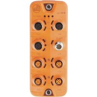
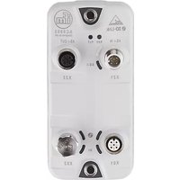
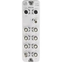
- Contens
- Preliminary note 4
- Safety instructions 7
- Functions and features 8
- Function 9
- Mounting 11
- Electrical connection 12
- Operating and display elements 16
- Set-up 19
- Configuration 20
- Preliminary note
- Content
- Legal and copyright information
- Symbols used
- Warnings used
- WARNING
- CAUTION
- NOTICE!
- User documentation for this device
- Modification history
- Safety instructions
- General
- Functions and features
- Function
- IO-Link
- IO-Link supply
- AS-interface
- Parameter setting
- Visual indication
- Mounting
- Mounting the device
- Electrical connection
- Notes
- IO-Link ports
- Connecting IO-Link devices for Class A operation
- Connecting IO-Link devices for Class B operation
- Connecting the unit
- Optional: Supply of an additional AS-i device (daisy chain)
- Operating and display elements
- Overview
- LED indicators
- Status LEDs
- Voltage supply
- IO-Link ports (Class A)
- Set-up
- Further steps:
- Configuration
- Notes
- Device structure
- Options for parameter setting
- Using the command interface
- Principle of the command processing
- Procedure: Sending acyclic command to the IO-Link master
- General process:
- Send command request
- Verify the validity of the command request
- Verify the availability of the command response
- Read command response
- Addressing the AS-i slave of the AC6000
- Addressing via AS-i master
- Addressing with addressing unit
- Adjusting the gateway profile
- Example: Setting the gateway profile
- Task:
- Solution:
- Configuring IO-Link ports
- Note: Device validation and data storage
- Reading / writing parameters of the IO-Link devices
- Requirements:
- Example: Reading parameter
- Course:
- Request parameter value
- Verify the availability of the IO-Link command response
- Read parameter value (first segment)
- Verify the availability of the IO-Link command response
- Read parameter value (first Segment)
- Example: Writing parameter
- Send first segment of the parameter value
- Read command status
- Send second segment of the parameter
- Verify the availability of the IO-Link command response
- Read command status
- Reading / writing process data
- Reading identification and diagnostic information
- Reading IO-Link events
- Resetting IO-Link master
- Updating the firmware
- Maintenance, repair and disposal
- Cleaning process
- Replacing IO-Link device
- Requirement:
- Set data storage
- Replace IO-Link device
- Factory settings
- Accessories
- Appendix
- Technical data
- Application
- Electrical data
- Inputs / outputs
- Inputs
- Outputs
- Interfaces
- Operating conditions
- Approvals / Tests
- AS-i classification
- Mechanical data
- AS-Interface
- Mapping: inputs and outputs of the IO-Link ports
- Command interface
- Structure of the command interface
- Overview: Acyclic commands
- 0x01: Read IO-Link Port Configuration Errors
- Diagnostic codes:
- 0x02: Write IO-Link Port Configuration
- 0x03: Read IO-Link Port Configuration
- 0x04: Read Input Process Data
- 0x05: Read Output Process Data
- 0x06: Write Output Process Data
- 0x07: Read Diagnosis Data
- 0x08: Factory Defaults
- 0x09: Set IO-Link Failsafe Data
- 0x0A: Write Parameter
- Legend:
- 0x0B: Read Parameter
- 0x0C: Read Device Name, Serial Number, HW and SW Revisions
- 0x0D: Update Firmware
- Index
- 0
- A
- C
- D
- E
- F
- G
- |
- L
- M
- N
- P
- R
- S
- T
- U
- V
- W
Brand : IFM
Model : AC6000
Category : Industrial interface