
AVR-2805 - Audio/Video Receiver DENON - Free user manual and instructions
Find the device manual for free AVR-2805 DENON in PDF.
Download the instructions for your Audio/Video Receiver in PDF format for free! Find your manual AVR-2805 - DENON and take your electronic device back in hand. On this page are published all the documents necessary for the use of your device. AVR-2805 by DENON.
USER MANUAL AVR-2805 DENON
M We greatly appreciate your purchase of the AVR-2805/985. M To be sure you take maximum advantage of all the features the AVR-2805/985 has to offer, read these instructions carefully and use the set properly. Be sure to keep this manual for future reference, should any questions or problems arise. “SERIAL NO. PLEASE RECORD UNIT SERIAL NUMBER ATTACHED TO THE REAR OF THE
TO QUALIFIED SERVICE PERSONNEL. The lightning flash with arrowhead symbol, within an equilateral triangle, is intended to alert the user to the presence of uninsulated “dangerous voltage” within the products enclosure that may be of sufficient magnitude to constitute a risk of electric shock to persons.
SAFETY INSTRUCTIONS Read Instructions — Al the safety and operating instructions should be read before the product is operated Retain Instructions — The safety and operating instructions should be retained for future reference Heed Warings — All warnings on the product and in the operating instructions should be adhered to. Follow Instructions — All operating and use instructions should be followed Cleaning — Unplug this product from the wall outlet before cleaning. Do not use liquid cleaners or aerosol cleaners. Attachments — Do not use attachments not recommended by the product manufacturer as they may cause hazards: Water and Moisture — Do not use this product near water — for example, near à bath tub, wash bowi, kitchen sink, or laundry tub: in a wet basement; or near a swimming pool; and the like Accessories — Do not place this product on an unstable cart, stand, tripod, bracket, or table. The product may fall, causing serious injury to à child or adult, and serious damage to the product. Use only with à cart, stand, tripod, bracket, or table recommended by the manufacturer, or sold with the product. Any mounting of the product should follow the manufacturer's instructions, and should use à mounting accessory recommended by the manufacturer. A product and cart combination should be e moved with care. Quick stops, excessive force, and uneven surfaces may cause the product and cart combination to overturn Ventilation — Slots and openings in the cabinet are provided for ventilation and to ensure reliable operation of the product and to protect it from overheating, and these openings must not be blocked or covered. The openings should never be blocked by placing the product on a bed, sofa, rug, or other similar surface This product should not be placed in à built-in installation such as a bookcase or rack unless proper ventilation is provided or the manufacturer's instructions have been adhered to. Power Sources - This product should be operated only from the type of power source indicated on the marking label. If you are not sure of the type of power supply to your home, consult your product dealer or local power company. For products intended to operate from battery power, or other sources, refer to the operating instructions Grounding or Polarization — This product may be equipped with a polarized alternating-current line plug (a plug having one blade wider than the other). This plug will fit into the power outlet only one way. This is a safety feature. lf you are unable to insert the plug fully into the outlet, try reversing the plug. If the plug should still fail to fit, contact your electrician to replace your obsolete outlet. Do not defeat the safety purpose of the polarized plug
ANEC ART 230, PART 1
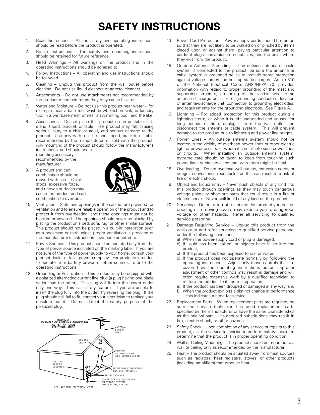
Power-Cord Protection — Power-supply cords should be routed so that they are not likely to be walked on or pinched by items placed upon or against them, paying particular attention to cords at plugs, convenience receptacles, and the point where they exit from the product. Outdoor Antenna Grounding — If an outside antenna or cable system is connected to the product, be sure the antenna or cable system is grounded so as to provide some protection against voltage surges and built-up static charges. Article 810 of the National Electrical Code, ANSI/NFPA 70, provides information with regard to proper grounding of the mast and supporting structure, grounding of the lead-in wire to an antenna discharge unit, size of grounding conductors, location of antenne-discharge unit, connection to grounding electrodes, and requirements for the grounding electrode. See Figure À Lightning — For added protection for this product during à lightning storm, or when it is left unattended and unused for long periods of time, unplug it from the wall outlet and disconnect the antenna or cable system. This will prevent damage to the product due to lightning and power-line surges: Power Lines — An outside antenna system should not be located in the vicinity of overhead power lines or other electric light or power circuits, or where it can fall into such power lines or circuits. When installing an outside antenna system, extreme care should be taken to keep from touching such power lines or circuits as contact with them might be fatal Overloading - Do not overload wall outlets, extension cords, or integral convenience receptacles as this can result in à risk of fire or electric shock Object and Liquid Entry - Never push objects of any kind into this product through openings as they may touch dangerous voltage points or short-out parts that could result in à fire or electric shock. Never spil liquid of any Kind on the product. Servicing — Do not attempt to service this product yourself as opening or removing covers may expose you to dangerous voltage or other hazards. Refer all servicing to qualified service personnel. Damage Requiring Service — Unplug this product from the wall outlet and refer servicing to qualified service personnel under the following conditions a) When the power-supply cord or plug is damaged, b) If liquid has been spilled, or objects have fallen into the product, c} Ifthe product has been exposed to rain or water, di If the product does not operate normally by following the operating instructions. Adjust only those controls that are covered by the operating instructions as an improper adjustment of other controls may result in damage and will often require extensive work by a qualified technician to restore the product to its normal operation, el Ifthe product has been dropped or damaged in any way, and # When the product exhibits a distinct change in performance — this indicates a need for service Replacement Parts — When replacement parts are required, be sure the service technician has used replacement parts specified by the manufacturer or have the same characteristics as the original part. Unauthorized substitutions may result in fire, electric shock, or other hazards. Safety Check— Upon completion of any service or repairs to this product, ask the service technician to perform safety checks to determine that the product is in proper operating condition. Wall or Ceiling Mounting — The product should be mounted to à wall or ceiling only as recommended by the manufacture. Heat — The product should be situated away from heat sources such as radiators, heat registers, stoves, or other products {including amplifiers) that produce heat
H INTRODUCTION Thank you for choosing the DENON AVR-2805/985 Digital A / V Surround Receiver. This remarkable component has been engineered to provide superb surround sound listening with home theater sources such as DVD, as well as providing outstanding high fidelity reproduction of your favorite music sources. As this product is provided with an immense array of features, we recommend that before you begin hookup and operation that you review the contents of this manual before proceeding.
[1] Before Using 4 F0] Muiti Zone 65-67 [2] Cautions on Installation 4 FT Surround 68-75 [31 Cautions on Handling 5 12 DSP Surround Simulation 76-82 [4] Features 5 F3 Listening to the Radio 83-84 [5] Connections 6-14 F4 Last Function Memory 85 [6] Part Names and Functions 15-17 F5 initialization of the Microprocessor 85 [7] Setting up the system 18-47 F6] Troubleshooting 86 [8] Remote Control Unit 48-57 FA Additional Information. 87-97 [8] operation 58-64 F8 Specifications 98 H ACCESSORIES Check that the following parts are included in addition to the main unit: Warranty { for North America model only } 1 © Service station list. 1 ® Remote control unit ) AM loop antenna. 1 ® FM indoor antenna...1 @ Omnidirectional microphone….1 (RC-974). 1 Oo] ® @ ®
[1] BEFORE usING Pay attention to the following before using this uni (D Operating instructions... ® R6P/AA batteries 3 + Moving the set + Store this instructions in a safe place. To prevent short circuits or damaged wires in the connection cords, After reading, store this instructions along with the warranty in a always unplug the power cord and disconnect the connection cords safe place between all other audio components when moving the set + Note that the illustrations in this instructions may differ from the actual set for explanation purposes. Before turning the power switch on Check once again that all connections are proper and that there are not problems with the connection cords. Always set the power switch to the standby position before connecting and disconnecting connection cords. 2] cAUTIONS ON INSTALLATION Z Noise or disturbance of the picture may be generated if this unit or any other electronic equipment using microprocessors is used near a tuner or TV. x re) OO x If this happens, take the following steps 7 222 + Install this unit as far as possible from the tuner or TV. 2 + Set the antenna wires from the tuner or TV away from this unit's Oo ovrer..esess O: power cord and input/output connection cords. À Noise or disturbance tends to occur particularly when using indoor 7 antennas or 300 Q/ohms feeder wires. We recommend using 4 inch/10 cm or more outdoor antennas and 75 Q/ohms coaxial cables. % 4 inch/10 em or more For heat dispersal, leave at least 4 inch/10 cm of space between the top, back and sides of this unit and the wall or other components. Wall
[3] cAUTIONS oN HANDLING Switching the input function when input jacks are not connected À clicking noise may be produced if the input function is switched when nothing is connected to the input jacks. If this happens, either tu down the MASTER VOLUME control or connect components to the input jacks: Muting of PRE OUT jacks, HEADPHONE jack and SPEAKER terminals The PRE OUT jacks, HEADPHONE jack and SPEAKER terminals include à muting circuit. Because of this, the output signals are greatly reduced for several seconds after the power switch is turned on or input function, surround mode or any other-set-up is changed. If the volume is turned up during this time, the output will be very high after the muting circuit stops functioning. Always wait until the muting circuit turns off before adjusting the volume. [a] FEATURES
Using advanced digital processing algorithms, Dolby Digital provides up to 5.1 channels of wide-range, high fidelity surround sound. Dolby Digital is the default digital audio delivery system for DVD and North American DTV.
2. Dolby Pro Logic Ix compatibility
Dolby Pro Logic IIx furthers the matrix decoding technology of Dolby Pro Logic Il to decode audio signals recorded on two channels into up to 7.1 playback channels, including the surround back channel. Dolby Pro Logic IIx also allows 5.1-channel sources to be played in up to 7.1 channels: The mode can be selected according to the source. The Music mode is best suited for playing music,the Cinema mode for playing movies, and the Game mode for playing games. The Game mode can only be used with 2-channel audio sources
3. Dolby Pro Logic II Game mode compatibility
In addition to the previously offered Music and Cinema modes, the AVR-2805/985 also offers a Game mode optimum for games
4. DTS (Digital Theater Systems)
DTS provides up to 5.1 channels of wide-range, high fidelity surround sound, from sources such as laser disc, DVD and specially-encoded music discs.
5. DTS-ES Extended Surround and DTS Neo:6
The AVR-2805/985 can be decoded with DTS-ES Extended Surround, à multi-channel format developed by Digital Theater Systems Inc The AVR-2805/985 can be also decoded with DTS Neo:6, a surround mode allowing 6.1 channels playback of regular stereo sources
6. DTS 96/24 compatibility
The AVR-2805/985 can be decoded with sources recorded in DTS 96/24, à mult-channel digital signal format developed by Digital Theater Systems Inc. DTS 96/24 sources can be played in the multi-channel mode on the AVR-2805/985 with high sound quality of 96 kHz/24 bits or 88.2 KHz/24 bits.
7. Pure Direct Mode/AL24 Processing
The AVR-2805/985 is equipped with à pure direct mode allowing the effects of the video and digital circuitry to be shut down when playing CDs or records to achieve the ideal environment for analog playback, resulting in extremely high quality music playback. It is also equipped with AL24 processing which compensates the input digital data to produce the near analog waveforms which would be in à nature with 24 bits quality. AL24 processing operates when PCM data such as CD is inputted!
8. Auto Setup/Room EQ
Use of the microphone for setup applications measures the presence of speakers, the distance to the speakers, and other information, and permits automatic setup. The characteristics of each speaker can also be corrected. + Whenever the unit is in the STANDBY state, the apparatus is still connected on AC line voltage. Please be sure to turn the power off [Loff) when you leave home for, say, a vacation.
9. Multi Zone Music Entertainment System
Multi Source Function: This units Multi Source function lets you select different audio sources for listening Different sources can thus be enjoyed in the main room (MAIN) and the subroom (ZONE2) simultaneously. 10.Future Sound Format Upgrade Capability via Eight Channel Inputs & Outputs For future multi-channel audio format(s), the AVR-2805/985 is provided with 7.1 channel (seven main channels, plus one low frequency effects channel) inputs, along with a full set of 7.1 channel pre-amp outputs, controlled by the 8 channel master volume control. This assures future upgrade possibilities for any future multi-channel sound format. 11.Front input Terminal The unit is equipped with a Front Input connector for the convenient connection of a video camera or other equipment. 12.Video Conversion Function The AVR-2805/985 is equipped with a function for up-converting video signals. Because of this, the AVR-2805/985's MONITOR OUT jack can be connected to the monitor (TV) with a set of cables offering a higher quality connection, regardless of how the player and the AVR- 2805/985's video input jacks are connected. 13.Component Video Switching In addition to composite video and "S" video switching, the AVR- 2805/985 provides 3 sets of component video (Y, Pe/Cs, Pr/Cr) inputs, and one set of component video outputs to the television, for superior picture quality. 14.TRIGGER OUT AVR-2805/985 is equipped with 2 systems of 12V TRIGGER OUT connections. Each output can be activated upon the selection of assigned. Main Zone inputs or zone2 inputs. 15.RS-232C Terminal includes a RS-232C port to support an AMX, Crestron integrated control system 16.AC INLET Detachable AC CORD is used. 17.Auto Surround Mode This function stores the surround mode last used for an input signal in the memory and automatically sets that surround mode the next time that signal is input. 18.Large-sized fluorescent display À large-sized fluorescent display is used which also permits a check of the input/output channels. 19.Audio delay This is a function for delaying the audio signal with respect to the video signal. (0 to 200 msec) 20.Preset Memory Tuning 56-Station AM/FM Random Preset Memory tuning,
[5] connections +Do not plug in the AC cord until all connections have been completed: «Be sure to connect the left and right channels properly (left with left, right with right) + Insert the plugs securely. Incomplete connections will result in the generation of noise. + Use the AC OUTLETS for audio eq them for hair driers, etc. ment only. Do not use + Note that binding pin plug cords together with AC cords or placing them near a power transformer will result in generating hum or other noise. eNoise or humming may be generated if a connected audio equipment is used independentiy without tuning the power of this unit on. If this happens, turn on the power of the this unit Connecting the audio components + When making connections, also refer to the operating instructions of the other components QUUT CD player Connecting a CD player — = 2222 | Connect the CD players analog output neo C0 jacks (ANALOG OUTPUT) to this unit's CD = = jack Jug cord jacks using pin plug cords: Connecting the AC OUTLETS AC OUTLETS TR ne Connecting a turntable + SNITCHED Connect the tumtable’s output cord to the AVR- 2805/285's PHONO jacks, the L_ left} plug to the L jeck, the R (right) plug to the right jack. NOTE: This unit cannot be used with MC cartridges directly. Use a separate head amplifier or Step-up transformer. IF humming or other noise is generated when he ground wire is connected, discannect the ground wire. {total capacity — 120 W (1 AJ} The power to these oullets is turned on and off in conjunction with the POWER operation switch on the main unit, and when the power is switched between on and standby from the remote control unit. No power is supplied from these outlets when this unit's power is at standby. Never connect equipment whose total capacity is above 120 W (1 AL. NOTE: Only use the AC OUTLETS for audio equipment. Never use them for hair driers, TVS or other electrical appliances. Connecting the pre-out jacks Use these jacks if you wish to connect extemal power amplifier(s) to increase the power of the front, center and surround sound channels, or for connection to powered loudspeakers. X To use Surround back with one speaker, connect the speaker to
CD player or other component equipped with digital output jacks = Ce 200 neo C0 0
MD recorder, CD recorder or other component equipped with digital input/output jacks © mit = sur our) | n°0 OPTICAL. g the DIGITAL jacks Use these for connections to audio equipment with digital output. Refer to "Setting the Digital in Assignment”. (See page 37) OUTUT. Connect NOTES: + Use 75 Qjohms cable pin cords for coaxial connections. + Use optical cables for optical connections, removing the cap before connecting
mur Route the connection cords, etc. In SUN à way that they do not obstruct the ventilation holes. TRIGGER OUT ‘Tum the DC 12V voltage on and off for the individual functions. For details, see "Setting the Trigger Setup”. (See page 441 AC 120 V, 60 Hz CD recorder or Tape deck NOTE: If humming noise is generated by 2 tape deck, etc. move the tape deck away. Connect the tape deck recording input jacks (LINE IN or REC) to this unit tape recording (CDR/TAPE OUT] jacks using pin plug cords. Connections for playback: Connect the tape deck's playback output jacks (LINE OUT or PB) to this units tape playback (CDR/TAPE IN) jacks using pin plug cords.
Connecting the video components + To connect the video signal, connect using a 75 Q/ohms video signal cable cord. Using an improper cable can result in a drop in video quality. + When making connections, also refer to the operating instructions of the other components. + The AVR-2805/985 is equipped with a function for up-converting video signals. +_ The signal connected to the video signal terminal is output to the S-Video and component video monitor out terminals. + The REC OUT terminals have no conversion function, so when recording only connect the video terminals: TION DPS ner Connecting a TV or DES tuner TV or DES the TV's or DES tuners video output jack (MDEO OUTPUT) to the {yellow TV or DES IN jack using à 75 Qohms video coaxial pin plug cord + Connect the TV's or DBS tuner's audio output jacks (AUDIO OUTPUT) to TVor DES IN jacks using pin plug cords LA) RL our DVD player or video disc player (VDPI, etc. [Connecting a DVD player or a video disc player (VDP) | DVD + Connect the video disc player's video output jack (MDEO OUTPUT) to the jack using à 75 Q/ohms video coaxial pin plug cord. + Connect the video disc players analog audio output jacks (ANALOG AUDIO OUTPUT) to the DVD IN jacks using pin plug cords: + VDP can be connected to the VDP jacks in the same way. (yellow) DVD IN Monitor TV MONITOR OUT + Connect the TV video input jack (VIDEO INPUT) to th MONITOR OUT jack using a 75 Qfohms video coaxial pin plug cord Note on connecting the digital input jacks + Only audio signals are inputs to the digital input jacks. For details. (See page 6) Video deck 2 or Ant auoio og Fa auoio + There are two sets of video deck (VCRI jacks, so two video decks can be connected for simultaneous recording or video copying. Video input/output connections: + Connect the video deck's video output jack (VIDEO OUT) to the ellowi VCR-1 OUT jack using 75 Mohms video coaxial pin plug cords: Connecting the audio output jacks + Connect the video deck's audio output jacks (AUDIO OUT) to the OUT jacks using pin plug cords: % Connect the second video deck to the VCR-2 jacks in the same way. ellow) VCR-T IN jack, and the video deck video input jack (VIDEO IN) to the VCR- VCR:1 IN jacks, and the video deck's audio input jacks (AUDIO IN to the
Connecting the video components equipped with S ideo jacks When making connections, also refer to the operating instructions of the other components À note on the S input jacks The input selectors for the S inputs The AVR-2805/985 is equipped with and Video inputs work in conjunction with each other. & function for converting video signals. The signal connected to the S-Video signal terminal is output to the composite video and component video monitor out terminals The REC OUT terminals have no cot nversion function, so when recording only connect the S-Video terminals: MONITOR OUT DVD player or video disc player (VDP} + Connect the TV's $ video input (S-VIDEO INPUT) to the MONITOR OUT jack using a S jack connection cord ne ES hs |E [Connecting a DVD player or a video disc player (VDP) |] Monitor TV DVD DVD IN jack using + Connect the DVD players S-Video output jack to the S-VIDEO + VDP can be connected to the VDP jacks in the same way. + Itis also possible to connect a video disc player, DVD player, video camcorder, game machine, etc, to the V.AUX jacks. a S-Video connection cord TV or satellite broadcast tuner DT — move] 0 00 = Connecting a TV or DBS tuner 2 Connect the TV' or DBS tuners S video output jack (S- VIDEO OUTPUT] to the TV or DBS IN jack using an S-Video connection cord. (e] Video deck 1 + Connect the video decks S output jack (S-OUT] to the VCR-1 IN jack and the video deck's S input jack {S-IN) to the VCR-1 OUT jack using S-Video connection cords. + Connect the video decks S output jack (S-OUT to the VCR-2 IN jack and the video deck's S input jack {S-IN) to the VCR-2 OUT jack using S-Video connection cords. Video deck 2 Connect the components’ audio inputs and outputs as described. (See page 7)
Connecting the video component equipped with Color Difference (Component - Y, Pr/Cr Pe/Cs) Video + When making connections, also refer to the operating instructions of the other components color difference output. (See page 41) COMPONENT= DVD player The signals input to the color difference (component) video jacks are not outputs to the VIDEO output jack (yellow) or the S-Video output jack Some video sources with component video outputs are labeled Y, Ca, Cr, or Y, Pb, Pr, or Y, R-Y, B-Y. These terms all refer to component video The function assigned to the component video input can be changed at the system setup. For details, see "Setting the Video Input Mode” Connecting a DVD pla Monitor TV DVD IN jacks + Connect the DVD players color difference (component} video output jacks {COMPONENT VIDEO OUTPUT) to the COMPONENT VIDEO-1 IN jack using 75 Qohms coaxial video pin-plug cords. + In the same way, another video source with component video outputs such as a TV/DBS tuner, etc., can be connected to the VIDEO-2 color difference {component} video jacks COMPONENT VIDEO IN Y &
MONITOR OUT jack + Connect the TV's color difference {component} video input jacks {COMPONENT VIDEO INPUT) to the COMPONENT MONITOR OUT jack using 75 Q/ohms coaxial video pin-plug cords. lécoboce -© O0 00000: maconme [rase The Video Conversion Function With the AVR-2805/985, the Video signal and the S-video signal which were inputted are converted mutually. And also the Video signal and the S-Video signal which were inputted are converted into à higher quality The flow of the this unit internal signals. ne me This units input jacks This unit's output jacks rites Vi | otre Vi + The color difference input jacks may be indicated differentiy on some TVs, monitors or video components ("Ca, Ca and Y” Y, B-Y and Ÿ”, "Pr, Pb and Y”, etc.). For details, carefully read the operating instructions included with the TV or other component. MONITOR OUT jacks The AVR-2805/985 is equipped with a function for up-converting video signals. Because of this, the AVR-2805/985's MONITOR OUT jack can be connected to the monitor (TV) with a set of cables offering a higher quality connection, regardless of how the player and the AVR- 2808/985's video input jacks are connected! Generally speaking, connections using the component video jacks offer the highest quality playback, followed by connections using the S-Video jacks, then connections using the regular video jacks (yellow) NOTE: Down-converting from the component video signal to the S-Video and composite video signal is not possible, so when not using the component video monitor output terminal connect the player using the S-Video or composite video input terminal Cautions on the video conversion function: When the component video terminals are used to connect the AVR- 2805/2985 with a TV (or monitor, projector, etc.) and the video (yellow or S video terminals are used to connect the AVR-2805/985 with à VTR, depending on the combination of the TV and VTR the picture may flicker in the horizontal direction, be distorted, be out of sync or not display at all when playing video tapes If this happens, connect à commercially available video stabilizer, etc., with a TEC (time base corrector) function between the AVR-2805/985 and the VTR, or if your VTR has a TBC function, turn it on
Connecting the antenna terminals DIRECTION OF BROADCASTING STATION ANTEUNR AM loop antenna assembly (Suppliech Fr FM ANTENNA Connect to the AM antenna terminal 75 Qlohms = 7 Co NS D same devants 7 CABLE and take out the @ ‘omécenine | Bendinine reverse = Section. PS
8. With the antenna L L ||
| ontpanysuble Lo) + D L surace. À : 1 Mount + D | PEINE TTL aached 10 à wal L ‘9006 OK AM OUTDOOR it An oi d ANTENNA station hole ‘6000 OK It Mt en val 1 ) ENoooR Note to CATV system installer: Re cRouND This reminder is provided to call the CATV system installers {Suppled) attention to Article 820-40 of the NEC which provides guidelines for proper grounding and, in particular, specifies that the cable ground shall be connected to the grounding + An F-type FM antenna cable plug can be connected directly system of the building, as close to the point of cable entry as practical. Connection of AM antennas Notes: T- Pushihe lever 2. Insertihe conduetor 3, Retum the lever + Do not connect wo FM antennes simultaneously + Even if an external AM antenna is used, do not disconnect the AM loop antenna 1 + Make sure AM loop antenna lead terminals do not touch 4 —, F M Et ù > Em metal parts of the panel. Connecting the external input (EXT. IN) jacks + These jacks are for inputting multi-channel audio signals from an outboard decoder, or a component with a different type of multi-channel decoder, such as a DVD Audio player, à multi-channel SACD player, or other future multi-channel sound format decoder. + When making connections, also refer to the operating instructions of the other components.
6-6 CORTE] Surround Subwoofer Front x For instructions on playback using the external input (EXT. IN) Decoder with 8- or 6-channel iacks. (See page 61) analog output = C..0
Perform the following operation before using an external controller connected to the RS-232C terminal
1. Press the ON/STANDBY button on the main unit and set the unit to the operating mode
2. Perform the operation to turn off the power from the external control
3. Check that the product has been set to the standby mode.
After checking the above, check the connections of the external controller. Operation is possible. [21ZONE2 SPEAKER OUT and PREOUT CONNECTIONS +_lf another power amplifier or pre-main integrated) amplifier is connected, the ZONE2 output terminals can be used to play a different program source in ZONE2 the same time: + ZONE? SPEAKER OUT can be used when "ZONE2" Speaker OUT cannot be used for MAIN ZONE. (See page 43) is selected at System Setup Menu “Power Amp Assign" ZONE2 Integrated pre-main amplifier Ha 617 INFRARED NSOR or power amplifier OUTPUT RC-616 INFRARED RÉTRANSMITTER AUX OUT
INPUT. DENON |Æ LE ec L Extension jacks for future use. NOTE: + The settings must be changed to use this _ speaker for ZONEZ (See page 43. (L)
In this case , Surround Back
Connecting the video component equipped with V. AUX jacks To connect the video signal, connect using à 75 Q/ohms video signal cable cord ! Video game ! i i Connecting a Video game component i OUTPUT i ! orne. woo our swoegour | ! + Connect the Video game component's output jacks ! ! 0 this units V. AUX INPUT jacks. LINE OUT VIDEO OUT: S-VIDEO OUT Connecting a video camera component + Connect the video camera component's output jacks to this unit's V. AUX INPUT jacks.
Speaker system connectio Connect the speaker terminals with the speakers making sure that like polarities are matched (© with ® , © with © }. Mismatching of polarities will result in weak central sound, unclear orientation of the various instruments, and the sense of direction of the stereo being impairedi When making connections, take care that none of the individual conductors of the speaker cord come in contact with adjacent terminal, with other speaker cord conductors, or with the rear panel. NOTE: NEVER touch the speaker terminals when the power is on. Doing so could result in electric shocks. Speaker Impedance + Speakers with an impedance of from 6 to 16 Q/ohms can be connected for use as front and center speakers + Speakers with an impedance of 6 to 16 Q/ohms can be connected for use as surround speakers: Be careful when using two pairs of front speakers (A + B) at the same time, since use of speakers with an impedance of less than 8 Q/ohms will lead to damage. +_ The protector circuit may be activated if the set is played for long periods of time at high volumes when speakers with an impedance lower than the specified impedance are connected. Connection the speaker terminals
1. Loosen by turning 2. Insert the cord
counterclockwise Either tightly twist or terminate the core wires.
8. Tighten by turning
clockwise. Connecting banana plugs QD Parare plus Tum clockwise to tighten, then insert the banana plug Connections + When making connections, also refer to the operating instructions of the other components Connection jack for subwoofer with builtin amplifier (super [ SURROUND SPEAKER SYSTEMS | | CENTER SPEAKER SYSTEM | | FRONT SPEAKER SYSTEMS (A) | woofer), etc: {R) + Precautions when connecting speakers If a speaker is placed near a TV or video monitor, the des |
colors on the screen may be disturbed by the speakers magnetism. If this should happen, move the speaker away to a position where it does not have this effect. NOTES: + To use Surround back with one speaker, connect the speaker to +_ The settings must be changed to use this speaker for ZONE2 (L) {R) See page 43 S S {L) {R)
+ This unit is equipped with a high-speed protection circuit. The purpose of this circuit is to protect the speakers under circumstances such as when the output of the power amplifier is inadvertently short-circuited and a large current flows, when the temperature surrounding the unit becomes unusually high, or when the unit is used at high output over a long period which results in an extreme temperature rise When the protection circuit is activated, the speaker output is cut off and the power supply indicator LED flashes. Should this occur, please follow these steps: be sure to switch off the power of this unit, check whether there are any faults with the wiring of the speaker cables or input cables, and wait for the unit to cool down if it is very hot. Improve the ventilation condition around the unit and switch the power back on If the protection circuit is activated again even though there are no problems with the wiring or the ventilation around the unit, switch off the power and contact a DENON service center. Note on speaker impedance + The protector circuit may be activated if the set is played for long periods of time at high volumes when speakers with an impedance lower than the specified impedance (for example speakers with an impedance of lower than 4 Q/ohms) are connected. lf the protector circuit is activated, the speaker output is cut off. Turn off the set's power, wait for the set to cool down, improve the ventilation around the set, then turn the power back on
[6] PART NAMES AND FUNCTIONS
Display DU DIGITAL à | TUNED AUTO [ats] @ \\PUT SIGNAL indicator The respective indicator will light corresponding to the input signal @ !\PUT SIGNAL CHANNEL indicator The channels included in the input source will light This displays bitstream signal channel This does not light when signals are being input to the ANALOG, EXT.IN or PCM connectors. @ niormation display This displays the surround mode, function name or setting value, etc. @ OUTPUT SIGNAL CHANNEL indicator The audio channels output from this unit will light © SPEAKER indicator This lights corresponding to the settings of the front speakers @ Decoder indicator This lights when each decoder is operating © MASTER VOLUME indicator This displays the volume level The Setup item number is displayed in System Setup.
@ MULTIIZONE) indicator ZONE2 mode is selected in ZONE2/REC SELECT. © REC OUT SOURCE indicator. REC OUT mode is selected in ZONE2/REC SELECT. ® AL24 indicator The AL24 indicator lights when the PURE DIRECT, DIRECT and STEREO mode is selected in the PCM input signal ® !\PUT MODE indicator This lights corresponding to the setting of the INPUT mode ® AUTO indicator This lights when the broadcast station is selected in the AUTO tuning mode. ® TUNED indicator This lights when an FM/AM broadcast has been received: ® STEREO indicator This lights when an FM stereo broadcast has been received
emote control unit + For details on the functions of these parts, refer to the pages given in parentheses ( ) LED (indicator) (50 - 57) ZONE 2 buttons (67) Mode selector buttons. (18, 49 - 51, 53 - 58) Input source selector buttons…(50 - 52, 59)
+ Once all connections with other AV components have been completed as described in "CONNECTIONS"” (see pages 6 to 14), make the various settings described below on the monitor screen using the AVR-2808/985'S on-screen display function These settings are required to set up the listening room's AV system centered around the AVR-2805/985 Use the following buttons to set up the system + Use the following buttons to set up the system.
Check that the remote control unit set to AMP mode.(TAPE, CDR/MD, CD) {Remote control unit} SYSTEM SETUP button Press this to display the system setup menu: CURSOR buttons Use these to move the cursors the left, right, up and down on the screen on scREEN DISPLAY ENTER button FRONT son — |
Press this to switch the display. Also use this button to complete the setting + System setup items and default values {set upon shipment from the factory)
1. Auto Setup/Room EQ
Auto Setup/Room EQ Defauit settings Set this to switch the surround back channels power amplifier for use for zone2 Power Amp 1 [Autos |'éssinment SURROUND BACK channel input jack. Manual EG | This parameter for optimiing the Room EQ with which the audio à = 2 Setup signals are produced from the speakers. Al Channel and Fréquency=0dB 3 [90m EQ | Sarthe foom EQ sening th Allo Assign or ench surround mode ai Direct Mode | Set he ONOFF setting of Room EG, in dhe case of he surround 4 Setup mode is in Direct or Pure Direct OFF 5 [ucngugaes | Set 1e 10 sun the ic Input jack ter use ter Mie er VAUX Le vie
Speaker Setup Defauit settings put the combination of speakers in your system end their ont So. nier booter | Surroun round act 1 Speaker corresponding sizes (SMALL for regular speakers, LARGE for full F S Center Sp. Suburoof S à Sp. S 1d Back Sp. Configuration | size, fulLrange) to automatically set the composition of the signals output from the speakers and the frequency response Large Small ves Small Small / 2spkrs This parameter is for optimizing the timing with which the audio] Front LE R Center | Subwoofer | SurroundL&R SEL & SER 2 | Delay Time | signals are produced from the speakers and subwoofer according to 1h listening position. 2R@6m [i266m) 12H 66m | 10K(80m) 10H (30m This adjusts the volume of the signals output from the speakers and | Front | FrontR | Center | Suround | Sumound | surouna | surouna | Goes 3 [Channel À submooter for the different channels in order to obtain optimum É RE effects. 04 | 04e odœ | odB | o48 | o4 | os 0d8 Crossover | Set 1he frequency (HA) below which the bass 50 of the various 4 Frequency speaker is to be output from the subwoofer. E0Hz 5 | Subucoterode | This selects the subwoofer speaker for playing deep bass signal LFE
Dolby Digital | Tum the audio compression on or off when down-mixing Dolby 2 | setup Digital signal. OFF Auto Suround 3 Mode Set the Auto surround mode function. Auto Surround Mode = ON 5.0ption Setup Option Setup Defauit settings 1 |PoveramP Set this to switch the surround back channel's power amplifier for Surround Back igger Out 3 Setup Set the Trigger Outi output for the each input sources. Assignment | use for zone2. Zone2 vol ‘This sets the output level the zone2 output jacks. 2 fi ‘This menu is not displayed, when *ZONE2" is selected at Option Variable sel Setup “Power Amp Assign”. ZONE=MAIN pHono | co |runer | core | ovo | vop | Tv | os |vcr:1|vcR2 |v aux orF |orr| or | oFr | où | où | où | on | où | on | on one à | ges Que | sue rage Qu ouut rte chi sauces prono | co [rues [comme] ou | vor [nv [08 [uen [vene vaux où Jon où | où Lovlov [on] où [ox | où | on 5 | Muting Level | This sets the amount of attenuation at audio output muting. —dBiminimum) On Screen 0 Display This sets whether or not to display the on-screen display that appears on the monitor screen when the controls on the remote control unit or main unit are operated. A setting to prevent flickering: On Screen Display = ON / Mode 1 7 | Setup Lock Set whether or not to lock the system setup settings so that they cannot be changed. Setup Lock = OFF NOTES: +_ The on-screen display signals are output with priority to the S-VIDEO MONITOR OUT jack during playback of a video companent. For example, if the TV monitor is connected to both the AVR-2805/985's S-Video and video monitor output jacks and signals are input to the AVR-2805/985 from a video source (VDP, etc.) connected to both the S-Video and video input jacks, the on-screen display signals are output with priority to the S-Video monitor output. If you wish to output the signals to the video monitor output jack, do not connect a cord to the S-VIDEO MONITOR OUT jack. (For details, see page 49.) +_The AVR-2805/985' on-screen display function is designed for use with high resolution monitor TVS, so it may be difficult to read small characters on TVs with small screens or low resolutions. +_The setup menu is not displayed when headphone are being used!
+ Speaker system layout Basic system layout + The following is an example of the basic layout for a system consisting of eight speaker systems and a television monitor Subwoofer Center speaker system Surround back speaker systems Front speaker systems Set these at the sides of the TV or screen with their front surfaces as flush with the front of the screen as possible. Surround speaker systems fore setting up the system Check that all the connections are correct, then turn on the main unit's power. Setup will not be possible when the unit is set to Pure Direct ON, or when the headphones are plugged in. Therefore, please cancel the mode or reverse the condition 2 sage Display the System Setup Menu up Menu Auto Setup/Room EQ SET 7 Speaker Setup Input Setup ce Advanced Playback Option Setup {Remote control unit} Exit NOTES: +_The System Setup menu composition is of a layered design that includes the related items below the large table title as contained in the tables of Pages 18 and
+ Wherever your position in System Setup, one more press of the System Setup button permits a move to one level higher.
Auto setup/Room EQ The Auto Setup function of this unit performs an analysis of the speaker system and measures the acoustic characteristics of your room to permit an appropriate automatic setting X When performing Auto Setup, an optional microphone is required for the setup M Measurement and setting details This sets the speaker connection mode, polarity, and bass reproduction ability This sets the optimum delay time from each speaker corresponding to the listening position This sets the volume that is output from each speaker. This sets the frequency response of each speaker NOTE: + A loud test tone is output during the measurement. Please consider this should you be planning night time measurements, and consider not allowing small children into the listening room at this time. Connecting the microphone for Auto Setup NOTES: 1 Connect the microphone for Auto Setup to the Setup Mic + When using other microphone see page 28 connector on the front panel of the unit el @i où où Place the microphone for Auto Setup at the actual listening position which will be at the same height as your ears. Use à tripod or level surface at positioning Mstening/position. El Setting the Auto Setup / Room EQ 1 Select Auto Setup / Room EQ" at the System Setup Menu contrèl unit} stem Setup Menu Auto Setup/Room EQ Speaker Setup Advanced Playback Option Setup
Set g the Auto Setup Select “Auto Setup” at the Auto Setup / Room EQ Menu. T. Auto Setup/Room EQ . Auto Setup Manual EQ Setup Room EQ Setup Direct Mode Setup . Mic Input Select contrèl unit} e Display the Auto Setup screen: {Remote control unit} Check the "Power Amp Assign" setting + When "Surround Back" is selected, the test tone during Auto Setup will be output from the Surround Back speaker. + When "ZONE2" is selected, change the setting to "ZONE2" The test tone during Auto Setup is set so that it will not be output to ZONEZ2 (Another room) Select the Power Amp Assign setting. @ Select “Surround Back” or “ZONE2" 1-1. Auto Setup
TPower Amp Assign te ASurroundBack à Start | Cancel4 {Remote control unit} NOTE: + When "ZONE2" is selected at System Setup Menu “Power Amp Assign”, surround back speaker is not displayed as the target of setup in "2-1.Speaker Contig.”. The results is reflected in "5-1.Power Amp Assign” 4 ® Select the Start” ur Power Amp Assign <SurroundBack à ŒStart« @ Press the Cursor left button Cancel«
Start the measurements. Measurement of each channel is performed as follows: Display : 2 .
LTI-HN-S0HSRH SEE 557 |
X1 Only the front speakers (A) is measured. Even if the front speakers (B) is set, the setting automatically switches to the front speakers (A measurements are completed. X2 Subwoofer speaker is measured twice: X3 When "ZONE2" is selected, this is not displayed After each channel is measured, "Calculating” appears The display switches to Auto Setup check screen automatically. NOTES: + Measurement is canceled when MASTER VOLUME is operated while the Auto Setup is performed + Set the volume to halfway and set the crossover frequency to the maximum or Low pass filter off if your subwoofer speaker can adjust the output volume and the crossover frequency. | once 1-1. Auto Setup 1-1 wSpeaker Config. Check Le D Delay Time Check Channel Level Check Sten: 1/9 Step:9/9 Store4 œCancel4 Retry 4 Cancel4 Auto Setup Auto Setup About automatic retry Remeasurement starts automatically to receive proper result of measurement. Remeasurement is performed to 2 times, and “Retry1” or "Rety2” is displayed on screen during remeasurement About the error message Auto Setup Front L Step: 1/9 wCancel4 These error screens will be displayed when performing the measurements of Auto Setup / Room EQ and the automatic measurements can not be completed because of the speaker arrangement, measurement environment, or other factors. Please check the following matters, reset the pertinent items, and measure again When there is too much noise in the room, the speakers may not be detected properly. Should this happen, perform the measurements when the noise level is low, or switch off the power of the equipment that is producing the noise for the duration of the measurements. @ This screen will be displayed when the speakers required for producing suitable reproduction have not been detected + The front L and front R speakers were not properly detected + Only one channel of the surround speakers was detected + Sound was output from the R channel when only one surround back speaker was connected + The surround back was detected, but the surround speaker was not detected. Check that the pertinent speakers are properly connected. (see page 13) Fe SE œéFront +
Retry« Cancel4 ® @ This screen will be displayed when the speaker polarity connected in reverse Check the polarity of the pertinent speakers. For some speakers, the
Auto Setup screen below may be réFront ph displayed even though the speakers are properly connected. Retry4 H so, select “Skip-@”. Cancel4 Skip4 This screen will be displayed when accurate measurements cannot be made due to the input level to the microphone being too high Set up the speakers so that their pos the listening position. Lower the volume of the subwoofer speaker. n is farther away from This screen will be displayed when the measurement microphone is not connected, or when all of the speakers have not been detected Connect the measurement microphone to the microphone connector. Check the speaker connections. Retry4 Cancel4
heck of the measurement results 1 Select the items. ÿ The measurement results of each item can be checked here 1-1. Auto Setup ê {0 wSpeaker Config. Check eue T Delay Time Check : Channel Level Check {Remote control unit} Store4 Retry 4 Cancel4« 2 Press the ENTER button and display the verification screen NOTE: (2) + When measurements have been made using the measurement microphone, speakers with à built- in filter such as subwoofers might be set with a value that differs from the physical distance {Remote control unit} because of the internal electrical delay, ISpeaker Config. Check] IDeley Time Check] Channel Level Check] Speaker Config Check Delay Time Check Channel Level Check SP. Cul Center Sp. 0 0. 08 Large [io 0 0. 08 Subwoofer 0 0. 08 Yes] oft @ © ®| Subwoofer 0. 08 Speaker Config Check Delay Time Check Channel Level Check Surround st 100 ETS 0. 0Œ None SR 1 0.0! SR 0. 04 s8L 10.0 SBL 0. 0@ None SBR 10.0 SBR 0. 0 8 © & 3 @ I the check ends, press the ENTER button again {Remote control uni < Select from the following three items based on the measurement results. T Auto Setup + Set with the checked measurement value + Perform the measurement again: Soeaker Config Check + Cancel the checked measurement value Delay Time Check Channel Level Check {Remote control unit} ! wStore4 Retry 4 Cancel4 When the “Store” is selected, all parameters are stored up D When the “Retry” is selected, it measures again 1. Auto Setup {Remote contrl uni
1-2 Setting the Manual EQ Setup Adjust the tone of the various speakers except subwoofer speaker while listening to the sound (music) Select “Manual EQ Setup” at the Auto Setup / Room 1 EQ Menu Auto Setup/Room EQ
X When the surround back speaker setting is set to 1spkr” at “Speaker Configuration”, this is set to "SB” 4 Select the frequency 1-2. Manual EQ Setup 4 Front L r 63 1 = .
500k TKkHz {Remote control unit} 2kHr 4kHr 8kHr Use the cursor left and right buttons to adjust the Gain level. + Each frequency can be adjusted the range from -6dB to +6dB in 0.5dB step {Remote control unit) Enter the setting 6 , The Auto Setup / Room EQ Menu reappears {Remote control unit}
Set g the Room EQ Setup Select the setting of an Equalizer that has been set with Auto Setup or Manual EQ.
{Remote control unit} Select “Room EQ Setup” at the Auto Setup / Room EQ Menu T. Auto Setup/Room EQ Auto Setup Manual EQ Setup Room EQ Setup Direct Mode Setup Mic Input Select EQ Parameter Check Exit
{Remote control unit} Select AII or Assign + AI The Equalizer to all Surround mode is set as once + Assign….The Equalizer to each surround mode is to set individually.
{Remote control unit} When the All is selected and press the ENTER button, display the Select the EQ Curve screen Select the Equalizer setting. + OFF.....….The Equalizer is not used + Normal …Adjust the frequency response of all speaker suitable for general surround system + Flat Adjust the frequency response of all speakers fiat This is suitable for music reproduction like ITU-R speaker setting. + Front.….…Adjusts the characteristics of each speaker to the characteristics of the front speakers + Manual ….Selects the setting value that was set in the Manual EQ setup NOTES: Setup. equalizer of “Normal”, “Front” and “Flat” cannot be used. Remote control unit When headphone is connected, the Room EQ cannot be used: 1-3. Room EQ Setup Select the EQ Curve Room EQ «Normal» The Equalizer setting of Normal, Flat and Front can be selected after performing the Auto When the speaker set as “None” with the Auto Setup is change to on manually, the The Equalizer setting can be selected by SURROUND PARAMETER button in Main unit or
{Remote control unit} Enter the setting The Auto Setup / Room EQ Menu reappears
Set g the Direct Mode Perform the ON/OFF setting of Room EQ when the surround mode is Direct or Pure Direct. 1 Select “Direct Mode Setup” at the Auto Setup / Room EQ Menu. 1. Auto Setup/Room EQ Manual EQ Setup
{Remote control unit} Enter the setting (x) The Auto Setup / Room EQ Menu reappears
1-5 Setting the MIC Input Select + Use this setting when using à microphone other than the included one for measurements when performing the auto setup procedure + The microphone included with the AVR-2805 is à measurement microphone designed specifically for use during the auto setup procedure Select “Mic” and connect the included microphone to the "SETUP MIC” minijack. When conducting the auto setup procedure using à separate high performance condenser microphone for measurements, select "V.AUX L” and connect the microphone to the "V.AUX Lch” pin jack X Please ask the DENON Authorized Service Center about the usable microphone other than the option setup
Select “Mic Input Select” at the Auto Setup / Room EQ Menu. Auto Setup/Room EQ . Auto Setup Manual EQ Setup Room EQ Setup . Direct Mode Setup Mic Input Select EQ Parameter Check Exit Display the Mic Input Select screen Select the Mic input jack or VAUX L jack 1-5. Mic Input Select DE «> Enter the setting The Auto Setup / Room EQ Menu reappears 1-6 Check the EQ parameter + The frequency characteristic of each speaker is rectified and the tone of the speaker is unified The EQ parameters that were set in Auto Setup can be checked This item is automatically displayed, after the measurement result of the “Auto Setup / Room EQ” is decided
Select the Equalizer curve. If the check ends,
Enter the Setting {Remote control unit} A Setting the Speaker Setup + Cross over Frequency and Subwoofer Mode Setup is not displayed when not using a subwoofer. Select "Speaker Setup” at the System Setup Menu {Remote control unit} Auto Setup/Room EQ
2-1 Setting the type of speakers +_The composition of the signals output to each channels and the frequency response are adjusted automatically according to the combination of speakers actually being used ef:
{Remote control unit} 2 Display the speaker config. screen as below {Remote control unit} Select “Speaker Config." at the Speaker Setup Menu 2. Speaker Setup
Crossover Frequency Subwoofer Mode Setup Exit Set whether speakers are connected or not and, if so, their size parameters. D Select the speaker 2-1. Speaker Config 2-1 Spesker Config Surround rSp re) ED» Sp. Back fps Du DRE ms TS EE Es À Select the parameter ee a \ A {Remote control unit} ENTER the setting 4 (x) The Speaker Setup Menu reappears {Remote control unit} NOTE: + Select "Large" or “Small” not according to the actual size of the speaker but according to the speaker's capacity for playing low frequency {bass sound below the frequency set for the Crossover Frequency) signals. If you do not know, try comparing the sound at both settings {setting the volume to a level low enough so as not to damage the speakers) to determine the proper setting + Parameters
Large Select this when using speakers that have sufficient performance for reproducing bass sound below the frequency set for the Crossover Frequency mode Small Select this when using speakers that do not have sufficient performance for reproducing bass sound below the frequency set for the Crossover Frequency mode. When this is set, bass sound with a frequency below the frequency set for the Crossover Frequency mode is sent to the subwoofer. None Select this when no speakers are installed Yes/No Select “Yes” when a subwoofer is installed, “No” when a subwoofer is not installed! 2spkrs/1spkr….Set the number of speakers to be used for the surround back channel % If the subwoofer has sufficient low frequency playback capacity, good sound can be achieved even when “Small” is set for the front, center and surround speakers
2-2 Setting the Delay Time + Input the distance between the listening position and each speakers to set the delay time for the surround playback Preparations: Meësure the distances between the listening position and the speakers (L1 to LS on the diagram at the right} L1: Distance between center speaker and listening position
Distance between front speakers and listening position L3: Distance between surround speakers and listening position L4: Distance between surround back speakers and listening position
Distance between subwoofer and listening position FL Center FR A 4 Subwoofer TL N] [ Listening position
{Remote control unit} Select "Delay Time” at the Sp: eaker Setup Menu 2 Speaker Setup Speaker Config. . Delay Time Channel Level Crossover Frequency Subwoofer Mode Setup PENSE Exit 2 Q {Remote control unit} Display the Delay Time screen 2-2. Delay Time Set The Distance To Each Speakers Do You Prefer In Meters? / In Feet? wMeters 4:» Feet {Remote control unit} Select the desired unit, meters or feet. 2-2. Delay Time Example: When “Feet” is selected Set The Distance To Each Speakers Do You Prefer In Meters? / In Feet? wMeters «:> [EXE 4 Once “Meters” or “Feet” is selected in step 3, the Delay Time screen appears automatically. 2-2. Delay Time Step Default
{Remote control unit} Select the speaker to be set The picture of the speaker selected blinks.
Set the distance between the center speaker and listening position The distance changes in units of 0.1 foot (0.03 meters) each time the button is pressed. Select te A the value closest to the measured distance. 2-2. Delay Time 2-2. Delay Time Step El Default {Remote control unit) «1 0.0 10.0ft 10.0ft de 10.0ft Subwoofer Example: When the distance is set to 12 feet for the center speaker RELOCATE BLINKING X If "Yes" is selected for “Default”, the settings are automatically reset to the default values Step Default Please note that the difference of distance for every speaker should be 20 ft (6.0 mi or less. If vou set an invalid distance, a CAUTION notice, such as screen right will appear. In this case, please relocate the blinking speaker(s) so that its distance is no larger than the value shown in highlighted line. X When "Step" is selected, you can select the unit of "1ft (0.1m}" or "O.1ft (0.01m)" Enter the setting 7 (2) The Speaker Setup Menu reappears The AVR-2805/985 automatically sets the optimum surround delay time for the listening room: {Remote control unit} NOTE: + lfthe distance unit is changed after the delay time is set, the settings are reset to the factory default values (see page 18) 2-3 Setting the Channel Level + Use this setting to adjust so that the playback level between the different channels is equal + From the listening position, listen to the test tones produced from the speakers to adjust the level Select “Channel Level" at the Speaker Setup Menu + The level can also be adjusted directly from the remote control unit. (For details, see page 68.)
T.Tonet {Remote control unit * AUtO: Adjust the level while listening to the test tones produced automatically from each speaker. + Manual Select the speaker from which you want to produce the test tone to adjust the level Level Clear Example: When the “Auto” mode is selected lerns Select “Test Tone Start" © 2-3, Channel Level Test Tone wTest Tone Start {Remote control unit} Level Clear Select “Yes” {Remote control unit} a. When the “Auto” mode is selected: Test tones are automatically emitted from each speaker. 2-3. Test Tone The test tones are emitted from each speaker in the following order, at 4-second intervals the first time and second time around, 2- second intervals the third time around and on x 1spkr {Remote control uni} ! : taste i ‘ pe EE EEE 2spkrs Example: When the volume is set to -11.5 dB U. " " while the test tone is being % When the surround back speaker setting is set to “1spkr” for Produced” from the Front Les “Speaker Configuration”, this is set to “SB" speaker Use the CURSOR left and right buttons to adjust all the speakers to the 23 same volume. The volume can be adjusted between -12 dB and +12 dB in units of 0.5 dB b. When the “Manual” mode is selected @ Select the speaker. {Remote control unit}
{Remote control unit} @ Adjust all the speakers to the same volume.
Enter the setting (3) The “Channel Level” screen reappears {Remote control unit} X To cancel the settings, press the CURSOR down to select "Level Clear” and “Yes” on the “Channel Level" screen, then make the settings again NOTE: + When adjusting the level of an active subwoofer system, you may also need to adjust the subwoofer's own volume control X When you adjust the channel levels while in the SYSTEM SETUP CHANNEL LEVEL mode, the channel level adjustments made will affect all surround modes. Consider this mode a Master Channel Level adjustment mode
- After you have completed the SYSTEM SETUP CHANNEL LEVEL adjustments, you can then activate the individual surround modes and adjust channel levels that will be remembered for each of those modes. Then, whenever you activate a particular surround sound mode, your preferred channel level adjustments for just that mode will be recalled. Check the instructions for adjusting channel levels within each surround mode. (See page 68) #% You can adjust the channel levels for each of the following surround modes: PURE DIRECT/DIRECT, STEREO, DOLBY/DTS SURROUND, 5/7 CH STEREO, WIDE SCREEN, SUPER STADIUM, ROCK ARENA, JAZZ CLUB, CLASSIC CONCERT, MONO MOVIE, VIDEO GAME, MATRIX and VIRTUAL. Setting the crossover frequency + Set the crossover frequency mode according to the speaker system being used 1 Select the Crossover Frequency” at the Speaker Setup Menu NX 2. Speaker Setup © speaker Contir Delay Time
Setting the low frequency distributi This screen is not displayed when not using à subwoofer and all speakers are set to small size + Set the subwoofer mode according to the speaker system being used 1 5o
{Remote control unit} Select the "Subwoofer Mode Setup” at the Speaker Setup
m5. Subwoofer Mode Setup Exit 2 , Display the Subwoofer mode screen. {Remote control unit} 3 Select the setting 2-5. Subwoofer Mode *Subuoaf ode {Remote control unit) Enter the setting (x) The Speaker Setup Menu reappears {Remote control unit} NOTES: — Assignment of low frequency signal range (2-1) — + The only signals produced from the subwoofer channel are LFE signals (during playback of Dolby Digital or DTS signals) and the low frequency signal range of channels set to "SMALL" in the setup menu. The low frequency signal range of channels set to "LARGE" are produced from those channels. — Crossover Frequency (2-4) — + When "Subwoofer" is set to “Yes” at the "Speaker Configuration Setting”, set the frequency (Hz) below which the bass sound of the various speakers is to be output from the subwoofer [the crossover frequency) + For speakers set to “Small”, sound with a frequency below the crossover frequency is cut, and the cut bass sound is output from the subwoofer instead! {e When the subwoofer set to “NO”, the bass sound is output from the speaker set as "Large”.) NOTE: For ordinary speaker systems, we recommend setting the crossover frequency to 80 Hz. When using small speakers, however, setting the crossover frequency to a high frequency may improve frequency response for frequencies near the crossover frequency. — Subwoofer mode (2-5) — + The subwoofer mode setting is only valid when "LARGE" is set for the front speakers and "YES" is set for the subwoofer in the "Setting the type of speakers”. (see page 30) + When the "LFE4+MAIN” playback mode is selected, the low frequency signal range of channels set to "LARGE" are produced simultaneously from those channels and the subwoofer channel In this playback mode, the low frequency range expand more uniformly through the room, but depending on the size and shape of the room, interference may result in a decrease of the actual volume of the low frequency range. + Selection of the "LFE ” play mode will play the low frequency signal range of the channel selected with "LARGE" from that channel only. Therefore, the low frequency signal range that are played from the subwoofer channel are only the low frequency signal range of LFE (only during Dolby Digital or DTS signal playback) and the channel specified as "SMALL" in the setup menu: + Select the play mode that provides bass reproduction with quantity. + When the subwoofer is set to “Yes”, bass sound is output from the subwoofer regardiess of the subwoofer mode setting in surround modes other than Dolby/DTS + In surround modes other than Dolby Digital and DTS, if the subwoofer is set to "YES”, the low frequency portion is always output to the subwoofer channel. For details, refer to "Surround Modes and Parameters”. (See page 68)
Setting the Digital In Assignment + This setting assigns the digital input jacks of the AVR-2808/985 for the different input sources. 1 At the Input Setup Menu select "Digital In Assign EMECITENTTT Digital In Assign
teh 2. Ext. In Subwoter Level 3° 3. Component In Assign < * + 4. Video Input Mode p n 6. Auto Tuner Presets {Remote control unit} Display the Digital Inputs screen ———_——_—_——————— ——— ISp'ay 1e Digital inpu 3-1 Digital In Assign {Remote control unit} Default 3 Select the digital input jack to be assigned to the input source û ® Select the input source @ Select the digital input jack (ere Select "OFF" for input sources for which no digital input jacks are used te) ( X If “Yes” is selected for “Default”, the settings are automatically reset to the default values {Remote control unit} Enter the setting 4 @ The Input Setup Menu reappears. {Remote control unit} NOTES: + The OPTICAL 8, 4 jacks on the AVR-2805/985's rear panel are equipped with an optical digital output jack for recording digital signals on a CD recorder, MD recorder or other digital recorder. Use this for digital recording between a digital audio source (stereo - 2 channel) and a digital audio recorder. + Do not connect the output of the component connected to the OPTICAL 3, 4 OUT jack on the AVR-2805/985'S rear panel to any jack other than the OPTICAL 3, 4 IN jack +_"PHONO” and "TUNER" cannot be selected on the Digital In Assignment
3-2 Setting the Ext. In Subwoofer Level + Set the method of playback of the analog input signal connected to the Ext.in Subwoofer. Input Setup
Video Input Mode Auto Tuner Presets 2 e Display to the Ext.in Subwoofer Level screen TE TT Se LT Subwoofer Level 441543 3 Select the desired setting. = Select according to the specifications of the player being used. Also refer to the +15dB (default) recommended. (0, +5, +10 or +15 can be selected.) Enter the setting. (2) The Input Setup Menu reappears: 3-3 Setting the Component In Assign + This setting assigns the color difference (componenti video input jacks of the AVR-2805/985 for the different input sources. 1 Select "Component In Assign” at the Input Setup EECTEETTT D Menu e 1Oigital In Assign
3 Select the component (Y, Pe/Ce and Pr/Cr) video input terminal to be assigned to the input source: 6 ÿ {Remote control unit} {Remote control unit ® Select the source @ Select the component selection D Video input terminal Select "NONE” for sources for which the component (Y, Pe/C8 and Pr/Cr) video input is not to be used. % When the default, “Yes”, is selected, the settings are reset to the factory defaults. Enter the setting The Input Setup Menu reappears: {Remote control unit} 1 D
Video Input Mode Auto Tuner Presets Exit 2 3-4. Video Input Mode e@ “UC > {Remote control unit} AUTO AUTO AUTO AUTO AUTO AUTO Default 3 ® Select the input source for which you want to set the Video Input Mode 80? {Remote contrèl unit} @ Select the mode as below. LrAUTO ++ COMPONENT ++ Svideo +» Video The details in each mode are as follows.
{Remote control unit} AUTO When there are multiple input signals, the input signals are detected and the input signal to be output from the video monitor output terminal is selected automatically in the following order: component video, S-Video, composite video Component: The signal connected to the component video terminal is always played! Video conversion is not conducted, so no image is output from the monitor output terminal when there is no input signal to the component terminal S-Video: The signal connected to the S-Video terminal is always played! The S-Video input signal is converted and output from the composite and component monitor output terminal Video. The signal connected to the composite video terminal is always played The composite video input signal is up-converted and output from the S-Video and component monitor output terminals
NOTE: Down-converting from the component video signal to the S-Video and composite video signal is not possible, so when not using the component video monitor output terminal connect the player using the S-Video or composite video input terminal. Cautions on the video conversion function: When the component video terminals are used to connect the AVR-2805/985 with à TV (or monitor, projector, etc.) and the video (yellow or S video terminals are used to connect the AVR-2805/985 with a VTR, depending on the combination of the TV and VTR the picture may flicker in the horizontal direction, be distorted, be out of sync or not display at all when playing video tapes. If this happens, connect a commercially available video stabilizer, etc. with a TBC (time base corrector) function between the AVR- 2805/985 and the VTR, or if your VTR has a TBC function, turn it on
{Remote control unit} Enter the setting. The Input Setup Menu reappears: 3-5 Auto Tuner Presets Use this to automatically search for FM broadcasts and store up to 56 stations at preset channels Al to 8, B1 to 8, C1 to 8, D1 to 8, El to 8, F1 to 8 and Gito8. NOTE: +_Ifan FM station cannot be preset automatically due to poor reception, use the “Manual tuning” operation to tune in the station, then preset it using the manual “Preset memory” operation
{Remote control unit} Display the Auto Preset Memory screen. 3-5. Auto Preset Memory Auto Tuning & Preset Station Memory Storing Preset Memory Start {Remote control unit} Press the CURSOR left button to select "Yes" “Search” flashes on the screen and searching begins “Completed” appears once searching is completed The display automatically switches to screen:
E1 Setting the Advanced Playback Select “Advanced Play back" at the System Setup System Setup Menu Menu. Speaker Setup Input Setup Lu Advanced Playback P Option Setup {Remote control unit} Exit Display the Advanced Playback Menu screen 4-1 Setting the Audio Delay This function allows you to adjust the time delay of the video and audio signals and store these settings for the different input sources The setting is made while watching a DVD or other software, so it is not made here By default, this is not displayed when no digital signals are being input For instructions on making the setting, refer to page 75. NOTE: The audio delay setting does not apply when it plays in the EXT. IN mode or in the analog input direct mode or stereo mode (TONE DEFEAT ON") 4-2 Setting the Dolby Digital Setup Sets the down-mixing method when not using a center speaker or surround speakers OFF: The dynamic range is not compressed ON: The dynamic range is compressed automatically according to the combination of speakers being used Select “Dolby Digital Setup” at the Advanced 4. Advanced Playback D Playback Menu
Press the ENTER button (3) Display the Dolby Digital Setup screen control unit} Select "ON" if you went to use the Compression, CRT INITTETT OFF” if you do not want to use it Downmix Option Setup] 4e Compression EN 4:» NOTE: When a center speaker or surround speakers, are not used the sound is played from the front speakers. Set “Compression” to "ON" if it seems that sound is distorted because the input level exceeds the allowable input for the front speakers Enter the setting. (2) The Advanced Playback Menu reappears. control unit}
Setting the Auto Surround Mode The surround mode used at last for the three types of input signals shown below is stored in the memory, and the signal is automatically played With that surround mode the next time it is input. Note that the surround mode setting is also stored separately for the different input sources Analog and PCM 2-channel signals (STEREO) 2-channel signals of Dolby Digital, DTS or other multi-channel format (DOLBY PLIIX cinema)
3) Multi-channel signals of Dolby Digital, DTS or other multi-channel format (DOLBY/DTS SURROUND)
X Default settings are indicated in (} % During playback in the PURE DIRECT mode, the surround mode does not change even if the input signal is changed
2 Dolby Digital Setup r3. Auto Surround Mode Press the ENTER button: (3) Display the Auto Surround Mode screen. 3 Select “ON” if you want to use the auto surround 4-3. Auto Surround Mode mode, “OFF” if you do not want to use it. Enter the setting. (3) The Advanced Playback Menu reappears. ON SCREEN X Contents stored in the auto surround mode can be Auto Surround Mode checked with the on-screen display. EREO 2ch:DOLBY PL 1x cine
5. 1rh:DOLBY/DTS SURROUNO]
[5 | Setting the Option Setup lens Select “Option Setup” at the System Setup Menu © 1. Auto Setup/Room EQ
Setting the Power Amplifier Assignment Make this setting to switch the power amplifier for the surround back channel to ZONE2. If ZONE? is selected, the signal that selected at ZONE? is output at "SURR. BACK ZONE2 PREOUT" terminals. Select Power Amp Assign” at the Option Setup Menu
Exit Press the ENTER button Display the Power Amp Assign screen Select “Surround Back” to use as the surround back channel, "Zone?" to use as Zone? out. Power Amp ASSIgn 5-1. Power Amp Assign Surroundbeck «: > S © When “Surround Back" is selected When “Zone2" is selected 1 Q control unit} Enter the setting The Option Setup Menu reappear. Setting the Zone2 Vol. Level Set the Zone? pre-out output level adjustment.
3 Select the desired setting. 5-2. ZoneZ Vol. Level Variable: The level can be adjusted freely using the buttons on the remote control unit. > -4048 O8 0 dB, -40 dB: The output level is fixed at the set level and the volume can no {Remote control unit} longer be adjusted NOTE: + When "ZONE2” is selected at System Setup Menu "E- 1.Power Amp Assign”, the Zone2 vol. Level is all set to “Variable” including preout level and this menu is not displayed Enter the setting, 4 a The Option Setup Menu reanpears {Remote control unit} 5-3, 5-4 Setting the Trigger Out Setup + Set the Trigger Out output 1 for the different input sources. Select "Trigger Out 1 Setup” at the Option Setup 1 5) Menu {Remote control unit}
5-5 Setting the Muting Level + This sets the amount of attenuation at audio output muting
Select Muting Level” at the Option Setup Menu
On Screen Display Setup Lock xit Display the Muting Level screen Select the desired setting. 5-5, Muting Level BE» 40% - 20% + -20 dB: It is turned down the volume to -20 dB from the present level. + 40 dB: It is turned down the volume to -40 dB from the present level. + — dB: Itis turned off the volume 4 Enter the setting. (x) The Option Setup Menu reappears + Use this to turn the on-screen display (messages other than the menu screens) on or off + Sets the on-screen display display mode Mode 1:_ Prevents flickering of the on-screen display when there is no video signal. Mode 2: Flickering is not prevented Use this mode if the on-screen display does not appear in the mode 1, as may happen according to the TV being used 1 Select “On Screen Display” at the Option Setup Menu. 5. Option Setup
D Select the On Screen Display mode Select “Model” or “Mode2" 5-6. On Screen Display nef [on FE © OA UE «> Mode2 {Remote contèl unit) {Remote control unit) Enter the setting. (2) The Option Setup Menu reappears. {Remote control unit} Protecting the setting The system setup settings can be locked so that they cannot be changed easily. 1 << Select Setup Lock” at the Option Setup Menu: option Star
. On Screen Display Setup Lock xit {Remote control unit} 2 Display the Setup Lock screen: {Remote control unit} 3 Select “ON”, to lock the system setup settings. 5-7 Setup Lock 57 EN « {Remote control unit} displayed when related buttons are operated + System setup settings {Remote control unit) + Surround parameter settings + Tone control settings + Channel level settings (including test tones) To unlock, press the System Setup button again and display the Setup Lock screen, then select “OFF” and press "ENTER" 4 Press the “ENTER"button to finalize the setting and exit the Option setup mode. When the setup lock function is activated, the settings listed below cannot be changed, and “SETUP LOCKED”" is X System setup is complete. Once these settings are made, there is no need to change them unless different AV components are connected or the speakers are repositioned.
After completing system setup This button can be pressed at any time during the system setup process to complete the process ste Press the SYSTEM SETUP button at the System Setup Menu su % The changed settings are entered and the on-screen display turns off. serv {Remote control unit) + On-screen display signals Signals input to the AVR-2805/985 On-screen display signal output VIDEO signal input jack | side signal input jack | Vide0 Signal output to VIDEO | Video signal output to S-_ | Video signal output to Color Difference (yellow) g put MONITOR OUT jack (ellowi | Video MONITOR OUT jack | (Component) Video MONITOR OUT jack 1 x x c o c 2 x Le [e) Le 3 x c c e] c 4 o c x o C (O: Signal *: No signal) On-screen signals output X: On-screen signals not output) NOTE: + When a component video signal is input and when the “Video Input Mode” is set to the component fixed mode at Input setup, the on-screen display is only displayed when the System Setup, Surround Parameters and On Screen buttons are operated
+ The included remote control unit (RC-974) can be used to operate not only the AVR-2808/985 but other remote control compatible DENON components as well. In addition, the memory contains the control signals for other remote control units, so it can be used to operate non-Denon remote control compatible products Inserting the batteries D Remove the remote control unit's rear cover. @ Set three RG6P/AA batteries in the battery compartment in the indicated direction Notes on Batteries Use R6P/AA batteries in the remote control unit. The batteries should be replaced with new ones approximately once a year, though this depends on the frequency of usage. Even if less than a year has passed, replace the batteries with new ones if the set does not operate even when the remote control unit is operated nearby the set. (The included battery is only for verifying operation. Replace it with a new battery as soon as possible.) When inserting the batteries, be sure to do so in the proper direction, following the “@” and "©" marks in the battery compartment To prevent damage or leakage of battery fluid + Do not use a new battery together with an old one + Do not use two different types of batteries. + Do not short-circuit, disassemble, heat or dispose of batteries in flames. Remove the batteries from the remote control unit when you do not plan to use it for an extended period of time If the battery fluid should leak, carefully wipe the fluid off the inside of the battery compartment and insert new batteries. When replacing the batteries, have the new batteries ready and insert them as quickly as possible. Using the remote control un
+ Point the remote control unit at the remote sensor on the main unit as shown on the diagram: + The remote control unit can be used from a straight distance of approximately 23 feet / 7 meters from the main unit, but this distance will be shorter if there are obstacles in the way or if the remote control unit is not pointed directly at the remote sensor. +_ The remote control unit can be operated at a horizontal angle of up to 30 degrees with respect to the remote sensor. NOTES: + It may be difficult to operate the remote control unit if the remote sensor is exposed to direct sunlight or strong artificial light + Do not press buttons on the main unit and remote control unit simultaneously. Doing so may result in malfunction + Neon signs or other devices emitting pulse-type noise nearby may result in malfunction, so keep the set as far away from such devices as possible
Operat DENON audio components 1 Use the mode selector buttons to select the component you want to operate % The function will change one step in the sequence described below each time the MODE SELECT button is pressed CR Te
ZONE2-#—TV — DBS/CABLE =— VCR
2 Operate the audio component + For details, refer to the component's operating instructions. % lt may not be possible to operate some models.
1. CD player (CD) system buttons
<< >>: Manual search (forward and reverse) = Stop > Play Hd, »1_: Auto search (to beginning of track) nu Pause DISC SKIP +: (for CD changers only)
3. MD recorder (MD), CD recorder (CDR) system buttons
<< >>: Manual search (forward and reverse) C] Stop > Play Hd, »1_: Auto search (to beginning of track) 0] Pause X Default setting = CDR
2. Tape deck (TAPE) system buttons
Dielele)le) (x) © o7 << Rewind > Fast forward = Stop : Forward play Pause Reverse play Switch between sides A and B
TUNING +,- : Tuning up/down BAND Switch between AM and FM bands MODE Switch between AUTO and MANUAL MEMORY: Preset memory SHIFT Switch preset channel range CHANNEL +, — : Preset channel up/down
(e>) =) Q © OS X The tuner can be operated in the amplifier (CD, CDR/MD, or TAPE) mode.
Preset memory The included remote control unit can be used to operate devices of different brands by registering the preset number corresponding to the brand of your device For some models the remote control unit or the device may not operate properly. In this case, use the learning function (page 53) to store your device's remote control signals in the included remote control unit Press the power ON/SOURCE button and the OFF button at the same time. + The LEARNED/TX indicator flashes. 0 on/souRcE Press the mode button of the equipment that is to be entered to a preset memory. se + The mode button flashes.
Referring to the included List of Preset Codes, use the number buttons to input the preset code (a 4-digit number) for the menufacturer of the component K whose signals you want to store in the memory. When stored correctly, the mode button and the LEARNED/TX indicator will light. To store the codes of another component in the memory, repeat steps 1 to 4. NOTES: + Depending on the model and year of manufacture, this function cannot be used for some models, even if the your device is listed on the included list of preset codes. + Some manufacturers use more than one type of remote control code. Refer to the included list of preset codes to change the number and check it out. + The preset memory can be set for one component only among the following: CDR/MD, DVD/VDP and DBS/CABLE. The preset codes are as follows upon shipment from the factory and after resetting
Operating a component stored in the preset memory 1 Press the mode selector button for the component you want to operate. NOTE: + For the DVD player remote control buttons, function names may differ according to manufacturer. control operation of the various components. Compare with the remote 2 Operate the component al video disc player (DVD, DVD SETUP) system buttons POWER _: Power on/standby (ON/SOURCE) <<»: Manual search {forward and reverse) CI] Stop > Play Hd »»1 : Auto search {to beginning of track) nu Pause 0-9, +10: 10 key DISC SKIP +: Disc skip {for DVD changer only) DISPLAY: Display MENU: Menu RETURN : Return SETUP _: Setup ENTER _: Enter AY, D : Cursor up, down, left and right + For details, refer to the components operating instructions. % Some models cannot be operated with this remote control unit. ô[+ url Dre) elle © DENON
2. Video dise player (VDP) system
3. Video deck (VCR) system
4. Monitor TV (TV), digital
buttons broadcast satellite (DBS) tuner POWER Power on/standhy Sr and cable (CABLE) system re (ON/SOURCE) © Q © buttons © © <>»: Manual search L dam POWER Power on/standby aus (forward and reverse) En (ON/SOURCE) ES 0] Stop MENU Menu Se > Play AY. D: Cursor up, down, left >) nu Pause and right œ Channel +, — : Channels ENTER Enter nn Ant CHANNEL : Switch channels F 9 9 9.0 + Q © 0 ©) @) oO) 0-9,410 : Channels ©) © © AA TVVCR _: Switch between TV AA and video player : O)] ©) © TV VOL +, : Volume up/down © @)] © = PS DISPLAY: Switch display = À oO] ® RETURN: Rotum © © © ue En EEE Soue es 90000 900QO (eXC>2) ©] (exc) ©] le: (eo)
NOTES: + The television can be operated in the DVD/VDP, VCR and TV modes. + For this CD, CDR, MD and TAPE components, buttons can be operated in the same way as for Denon audio components.
If your AV component is not a Denon product or if it cannot be operated using the preset memory, it can be controlled with the accessorious remote control unit by storing its remote control signals in the remote control unit. For some remote control signals it is not possible to “learn” the signals or the device will not operate properly. In such cases use the remote control unit included with the device to operate it Press the USE/LEARN button with the tip of a pen etc., to set the learn mode. + Both the mode selector buttons and LEARNED/TX indicator flash Flashes
Press the mode button of the equipment for which learning is desired! + Mode button and LEARNED/TX indicator flash Press the button that is to be learned: 3 The LEARNED/TX indicator stops flashing and the mode button lights + Mode button and LEARNED/TX indicator flashed if a button that cannot be “learned” is pressed. + To cancel, press the USE/LEARN button Point the remote control units directly at each other and press and hold in the button on the other remote control unit which you want to "learn" 6 To “learn other buttons, repeat steps 2 to 5 Other remote control unit Once the learning operation is completed, press the USE/LEARN button again The mode button and the LEARNED/TX indicator stop flashing and the learning mode is cancelled The mode button and the LEARNED/TX indicator lights, | release the button on the other remote control unit + The mode button and the LEARNED/TX indicator start flashing again: Check that the stored codes work proper. NOTES: + If the codes could not be stored, the LEARNED/TX indicator start flashing rapidly. For limited number of models, codes cannot be stored in RC-974. If the mode button and LEARNED/TX indicator start flashing rapidiy, this means that the memory is already full, and the code you have just attempted to store was not stored. To “learn” that code, first perform the resetting operation. (See page 56.)
System call The accessorious remote control unit is equipped with "system call” function allowing a series of remote control signals to be transmitted by. pressing a single button: This function can be used for example to turn on the amplifier's power, select the input source, turn on the monitor TV's power, turn on the source component's power and set the source to the play mode, all at a signal button: X£ à {1) System call buttons s @ Yo Up to 10 signals each can be stored at the "CALL1” and “CALL2" (e] (e] buttons {2) Storing system call signals Press the power ON/SOURCE button and or. aise
1 Q the OFF button at the same time 1 a) | sen | C1 + The LEARNED/TX indicator flashes. OwIsauRcE Press the mode buttons of the equipment that is to be registered to System Call Press the CALL 1 button + The mode selector buttons and LEARNED/TX indicator flash
; DO OO: 00C Press the buttons whose remote control signals you want to store one by one Repeat steps 3 and 4 to register the desired buttons: Press the CALL1 or CALL2 button and sen YA register System Call NOTES: + The remote control signals for the buttons pressed while storing the system call signals are transmitted when the buttons are pressed, so cover the remote sensor or take other measures so that the components do not operate while the signals are being stored + The mode button and LEARNED/TX indicator flashing rapidly if you have already stored the maximum number of signals
(3) Using the system call function Press the button at which the system call signals have been stored! + The stored signals are transmitted successively. Punch Through {1) Punch through button Buttons used in the CD, CDR/MD, TAPE, DVDIVDP, and VCR modes can be assigned to the buttons shown on the diagram at the right which are not normally used in the TV and DBS/CABLE modes. For example, when the CD mode is set to the punch through mode in the TV mode, the CD mode's PLAY, STOP. MANUAL SEARCH, AUTO SEARCH, PAUSE and DISC SKIP buttons’ signals are sent in the TV mode {2) Making the punch through setting Press the power ON/SOURCE button and
1 the OFF button at the same time. + The LEARNED/TX indicator flashes. OI sauRcE LEARNED/TX indicator flash 2 Press the B (play) button CR + TV and DBS/CABLE mode buttons and 3 qe Press the mode button of the equipment CD) | ‘0 Which Punch Through is to be set + The CD, CDR/MD, TAPE, DVDNWDP, and VCR mode buttons and LEARNED/TX indicator will flash Press the mode button of the equipment that is to be punched through + The mode button that was set will light
{1) Resetting “learned” buttons Press the USE/LEARN button with the tip of a pen, etc., to set the learn mode + The mode selector buttons and LEARNED/TX indicator = sise Ô| + 3 flash Flashes
O OO Press the mode button of the equipment that is to be reset + Mode button and LEARNED/TX indicator flash Ke)
O:OÏ O:0i Hold for 4 seconds or longer the mode button of the 3 equipment that is to be reset and the ON/SOURCE button +_The mode button and the LEARNED/TX indicator will again flash, and the learned remote control signal of the selected ææ (© equipment will be deleted anrsounce Press the USE/LEARN button.
{2) Resetting the punch through setting
OwIsauRcE Press the power ON/SOURCE button and the OFF button at the same time + The LEARNED/TX indicator flashes.
Press the B (play) button + TV and DBS/CABLE mode buttons and LEARNED/TX indicator flash 3 one Press the mode button of the equipment {TV or DBS/CABLE) that is to be reset. + The CD, CDR/MD, TAPE, DVD/VDP, and VCR mode buttons and LEARNED/TX indicator will flash 4 au Press the mode button of the equipment that is to be reset again + During the resetting operation, the selected mode button and the LEARNED/TX indicator will light; they will return to steady state upon completion 116 —_
[9] oPERATION 1 Refer to "CONNECTIONS" (pages 6 to 13) and check that all _—_— connections are correct. Select “AMP” using the AMP button == {only when operating with the remote control unit) =
The power turns on and indicator is light Set the power switch to this position to turn the power on and off from the included remote control unit ° MOF The power turns off and indicator is off. In this position, the power cannot be turned on and off from the remote control unit Turn on the power Press the POWER ON/STANDBY switch (button) ovIsauRcE ON !STANDEY \ When pressed, the power turns on and the display lights. The sound is muted for several seconds, after which the unit operates normally. ©) When pressed again, the power turns off, the standby mode is set and the display turns off The front speakers switch as shown below each time the Q FRONT SPEAKER button is pressed. [e) gran SERER {Remote control uni) (Mein uni)
°00e Gssamo (): oWo qu) 1 Select the input source to be played Example: CD œ runeron {Remote control unit X To select the input source when ZONE2/REC OUT, VIDEO SELECT or ( TUNING PRESET is selected, press souR| the SOURCE button then operate the input function selector. {Main unit} {Main unit} Select the input mode + Selecting the analog mode Press the ANALOG button to switch to the analog input. {Remote control unit} ANALOG {Main unit} Selecting the external input (EXT. IN) mode Press the EXT. IN (on the EXT. IN button on the remote control unit) to switch the external input {Remote control unit} EXT.IN {Main unit Selecting the AUTO, PCM and DTS modes The mode switches as shown below each time the INPUT. MODE button is pressed
MODE {Remote control unit} {Main unit} Note on playing a source encoded with DTS + Noise may be generated at the beginning of playback and while searching during DTS playback in the AUTO mode. If 50, play in the DTS mode. © 6 0 Input mode selection function Different input modes can be selected for the different input sources. The selected input modes for the separate input sources are stored in the memory. ® AUTO (auto mode) In this mode, the types of signals being input to the digital and analog input jacks for the selected input source are detected and the program in the AVR-2805/985's surround decoder is selected automatically upon playback. This mode can be selected for all input sources other than PHONO and TUNER. The presence or absence of digital signals is detected, the signals input to the digital input jacks are identified and decoding and playback are performed automatically in DTS, Dolby Digital or PCM {2 channel stereo) format. If no digital signal is being input, the analog input jacks are selected Use this mode to play Dolby Digital signals @ PCM (exclusive PCM signal playback mode) Decoding and playback are only performed when PCM signals are being input Note that noise may be generated when using this mode to play signals other than PCM signals ® DTS exclusive DTS signal playback mode) Decoding and playback are only performed when DTS signals are being input @ ANALOG (exclusive analog audio signal playback mode) The signals input to the analog input jacks are played ® EXT. IN (external decoder input jack selection mode) The signals being input to the external decoder input jacks are played without passing through the surround circuitry. NOTE: + Note that noise will be output when CDs or LDs recorded in DTS format are played in the “PCM” (exclusive PCM signal playback or “ANALOG” (exclusive PCM signal playback! mode. Select the AUTO or DTS mode when playing signals recorded in DTS from à laser disc player or CD player.
3 Select the play mode Example: Stereo suRRoUND seuecr STEREO MODE ( {Remote control unit) {ain unit X% To select the surround mode while adjusting the surround parameters, channel volume or tone control, press the surround mode button then operate the selector. surRouND MODE {Main unit} Start playback on the selected component. + For operating instructions, refer to the component's manual 5 Adjust the volume.
{Remote control unit} ‘The volume level is displayed on the master volume level display. X The volume can be adjusted within the range of -80 to O to 18 dB, in steps of 0.5 dB. However, when the channel level is set as described on page 32-34 or pages 68 and 69 if the volume for any channel is set at +0.5 dB or greater, the volume cannot be adjusted up to 18 dB. (In this case the maximum volume adjustment range is "18 dB — (Maximum value of channel level)".) Input mode display Depending on the input signal. + In the AUTO mode + In the DIGITAL PCM mode + In the DIGITAL DTS mode + In the ANALOG mode + Inthe EXT.IN mode Input signal display + DOLBY DIGITAL O0 DIGITAL + DTS + PCM Input mode when playing DTS sources + Noise will be output if DTS-compatible CDs or LDs are played in the “’ANALOG" or "PCM" mode When playing DTS-compatible sources, be sure to connect the source component to the digital input jacks (OPTICAL/COAXIAL) and set the input mode to "DTS"
DIG. X The lights when digital signals are being input properly. If the indicator does not light, check whether the digital input component setup (page 37) and connections are correct and whether the component's power is turned on: X AL24 processing is activated when PCM signals are played while the surround mode is set to PURE DIRECT, DIRECT, STEREO NOTE: + The indicator will light when playing CD-ROMs containing data other than audio signals, but no sound will be heard
{Remote control unit} {Main unit} Once this is selected, the input signals connected to the FL {front left}, FR (front right, C (center), SL (surround left), SR {surround right), SBL (surround back lefti and SBR (surround back right) channels of the EXT. IN jacks are output directly to the front [left and right, center, surround (left and right} and surround back left and right} speaker systems as well as the pre-out jacks without passing through the surround cireuitry. In addition, the signal input to the SW (subwoofer) jack is output to the PRE OUT SUBWOOFER jack EXT.IN Cancelling the external input mode To cancel the external input (EXT. IN) setting, press the input mode (AUTO, PCM, DTS) or ANALOG button to switch to the desired input mode. (See page 59) MODE ANALOG RRR ER {Remote control unit} {Main unit) + When the input mode is set to the external input (EXT. IN), the surround mode (DIRECT, STEREO, STANDARD, 5/7CH STEREO, WIDE SCREEN or DSP SIMULATION) cannot be set cocoo@sssse °O°
NOTES: + In play modes other than the external input mode, the signals connected to these jacks cannot be played. In addition, signals cannot be output from channels not connected to the input jacks + The external input mode can be set for any input source. To watch video while listening to sound, select the input source to which the video signal is connected, then set this mode: + Ifthe subwoofer output level seems to high, set the "SW ATT” surround parameter to "ON"
Playing audio sources (CDs and DVDs) The AVR-2805/985 is equipped with three 2-channel playback modes exclusively for music: Select the mode to suit your tastes. PURE DIRECT mode 1 In this mode, the music is played with an extremely high level of sound quality. When this mode is set, all the video-related circuits are turned off so that music signals can be reproduced with high quality When an analog mode is selected, the digital processing circuitry is also turned off to achieve analog sound with even higher purity. (See NOTES) PURE DIRECT {Remote control unit} (Min unit} Use this mode to achieve good quality 2-channel sound while watching images. In this mode, the audio signals bypass such circuits as the tone circuit and are transmitted directly, resulting in good quality sound 2 DIRECT mode DIRECT {Remote control unit} STEREO mode Use this mode to adjust the tone and achieve the desired sound while watching images STEREO {Remote control unit} NOTES: +_The system setup function cannot be used when the PURE DIRECT mode is set. To use the system setup function, cancel the PURE DIRECT mode The ZONE2 video output is not output in the PURE DIRECT mode The channel level and surround parameters in the PURE DIRECT mode are the same as in the DIRECT mode When the PURE DIRECT button is pressed while in the PURE DIRECT mode, the PURE DIRECT mode is cancelled The subwoofer's channel level must be set to “OFF” in order to turn off the digital circuit in the PURE DIRECT mode
After starting playback [1] Adjusting the sound quality (TONE) The tone control function will not work in the PURE DIRECT and the DIRECT mode roc The tone switches as follows each time 1 CONTROL the TONE CONTROL button is pressed BASS <> TREBLE {Main unit) With the name of the volume to be adjusted selected, turn the SELECT knob to adjust the level 2 seuecr (O) {Main unit) + To increase the bass or treble: Turn the control clockwise {The bass or treble sound can be increased to up to +6 dB in steps of 1 dB.) + To decrease the bass or treble: Turn the control clockwise {The bass or treble sound can be decreased to up to -6 dB in steps of 1 dB.) = CET If you do not want the bass and treble to be adjusted, turn on the tone defeat mode. X The signals do not pass through the bass and treble adjustment circuits, providing higher quality sound TONE DEFEAT. {Main unit) L2]Listening over headphone PHONES Plug the headphone’ plug into the jack % Connect the headphone to the PHONES jack: The pre-out output (including the speaker output} is automatically 1 turmed off when headphone are connected. [31 Turning the sound off temporarily (MUTING) Use this to mute the audio output temporarily. Press the MUTING button % Cancelling MUTING mode. Press the MUTING button again MUNG {Remote control unit} 14] Combining the currently playing sound with the desired image Simulcast playback 1 Use this switch to monitor a video source other than the audio source Press the VIDEO SELECT button, turn the FUNCTION knob until the desired source appears on the display. a = (O) {Main unit) (Main unit} % Cancelling simulcast playback. + Select “SOURCE” using the VIDEO SELECT button and the FUNCTION button + Switch the program source to the component connected to the video input + Press the SOURCE button NOTE: To prevent hearing loss, do not raise the volume level excessively when using headphone. © 6 &> L_:
15] Checking the currently playing program source, etc. On screen display 1 oNscREEn + Each time an operation is performed, a description of that operation appears Èr on the display connected to the units VIDEO MONITOR OUT jack. Also, the units operating status can be checked during playback by pressing the remote control units ON SCREEN button Such information as the position of the input selector and the surround parameter settings is output in sequence {Remote control unit} Front panel display Descriptions of the unit's operations are also displayed on the front panel display. In addition, the display can be switched to check the unit's operating status while playing à source by {Main unit) pressing the STATUS button Using the dimmer function DER + Use this to change the brightness of @ the display, | The display brightness changes in four steps (bright, medium, dim and off) by pressing the main units DIMMER {Main unit) button repeatediy. | O1 @ ©» nm
© 6 0 1—6 Iti-source recording/playback Playing one source while recording another (REC OUT mode) 1 Press the ZONE2/REC button {Main unit) With "RECOUT SOURCE" displayed, FUnCTION turn the FUNCTION knob to select the source you wish to record + When the FUNCTION goes around, it tum to the "REC" indicator and the indicator of the selected source light.
{Main unit) Set the recording mode + For operating instructions, refer to the manual of the component on which you want to record’ To cancel, turn the function knob and 4 FUnCTION select "SOURCE" {Main unit)
NOTES: + Recording sources other than digital inputs selected in the REC OUT mode are also outputted from the Zone2 preout jacks + Digital signals are not outputted from the analog REC OUT jacks
MULTI ZONE Multi-zone playback with multi-source
MULTI ZONE MUSIC ENTERTAINMENT SYSTEM
When the outputs of the "ZONE2” OUT terminals are wired and connected to integrated amplifiers installed in other rooms, different sources can be played in rooms other than the main zone in which this unit and the playback devices are installed. (Refer to ZONE2 on the diagram below.) ZONE2 SPEAKER OUT can be used when "ZONE2" is selected at System Setup Menu “Power Amp Assign”.in this case, Surround Back Speaker OUT cannot be used for MAIN ZONE. (See page 43.) When a sold separately room-to-room remote control unit (DENON RC-616, 617 or 618) is wired and connected between the MAIN ZONE and ZONEZ, the remote-controllable devices in the main zone can be controlled from ZONE2 using the remote control unit X To control playback devices other than the ones above, either use that device's remote control unit or preset à separately sold programmable remote control unit. NOTES: + For the AUDIO output, use high quality pin-plug cords and wire in such a way that there is no humming or noise + For instructions on installation and operation of separately sold devices, refer to the devices’ operating instructions: + When the PURE DIRECT mode is set for the main zone, no signals are output to the ZONE2 video terminals + Signals are output from the ZONEZ video terminals even when ZONEZ is set to "OFF"
MULTI ROOM MUSIC ENTERTAINMENT SYSTEM
M When using the SURR.BACK/ZONEZ amplifier as the SURROUND BACK. The AVR-2805/985 is equipped with pre-out terminals for which the volume is adjustable (ZONE2) and composite video output terminals as the ZONE2 output terminals. {1)System configuration and connections example Using external amplifier MAIN ZONE 7.1-channel systems (VARIABLE OUT) or Power Amplifier O Monitor O ZONE 2 @) O Monitor FL Center FR
(separately sold) control line — MULTI SOURCE AUDIO signal cable CES ZONE2 VIDEO signal cable # Refer to CONNECTIONS on pages 6 to 13.
Æ When using the SURR.BACK/ZONE2 amplifier as the ZONE2. + ZONE? speaker out can be used when "ZONE2" is selected at System Setup Menu “Power Amp Assign”. In this case, Surround Back PREOUT and speaker out cannot be used for MAIN ZONE. + The AVR-2805/985 is equipped with preout terminals for which the volume is adjustable (ZONE2) and speaker out terminals for which the volume is adjustable (ZONE2) and composite video output terminals as the ZONEZ output terminals: {1) System configuration and connections example Using this units internal amplifier as the ZONE2 MAIN ZONE 5.1-channel systems Monitor O O KL KL
[1] Outputting a program source to an amplifier, etc., in a different room (ZONE2 mode)
= on mor Press the "Power switch" button. {Main unit) Press the ZONE2/REC button. The display switches as follows each time the button is pressed
With "ZONE2 SOURCE" displayed, turn the FUNCTION knob and select the source you wish to output. + The display switches the selected source {Main unit) Start playing the source to be output. + For operating instructions, refer to the manuals of the respective components. To cancel, turn the function knob and select "SOURCE" {Main unit) NOTES: + The signals of the source selected in the ZONE2 mode are also output from the VCR-1, VCR-2 and CDR/TAPE recording output jacks + Digital signals are not output from the ZONE2 audio output jacks + Refer to page 65, 66 about the MULTI ZONE connections: [21Remote control unit operations during multi-source playback (selecting the input source) This operation is not possible in the REC OUT mode This operation is possible when ZONE2 mode is selected
> % To turn off the ZONE2 mode, press the ZONE2 "OFF" button. {Remote control unit} Press the input source button + The ZONE? source switches directly. The output level of the ZONE2 OUT O) terminals can be controlled using the VOLUME + and - buttons on the remote control unit ©) The output level of ZONE2 OUT can be controlled only if ZONE2 vol. level is set “Variable” at Zone2 Control in System Setup Menu. (see page 43,44) {Remote control unit} % DEFAULT SETTING (ZONE2 VOLUME LEVEL) --- dB (MINIMUM) CHANNEL When the ZONE2 SOURCE function is set to TUNER, the preset channel can be selected using the CHANNEL + and - buttons on the remote control unit {Remote control unit} Pan oi output can be turned on and off with the “MAIN ON/OFF" button. O OÙ Ex me
[ni] surrouND efore playing with the surround function + Before playing with the surround function, be sure to use the test tones to adjust the playback level from the different speakers. This adjustment can be performed with the system setup (see page 32-34) or from the remote control unit, as described below + Adjusting with the remote control unit using the test tones is only possible in the “Auto” mode and only effective in the STANDARD {DOLBY/DTS SURROUND) modes. The adjusted levels for the different modes are automatically stored in the memory. Press the TEST TONE button: (ED) {Remote control unit} Test tones are output from the different D speakers. Use the channel volume adjust buttons to adjust so that the volume of the test tones is the same for all the speakers. {Remote control unit} 3 ) After completing the adjustment, press the TEST TONE button again {Remote control unit} © 6 0 + After adjusting using the test tones, adjust the channel levels either according to the playback sources or to suit your tastes, as described below. Select the speaker level you want to adjust. 1 Q {Remote control uni} The channel switches as shown below each time the button is pressed
ns 5 me] [Sw} 2 Adjust the level of the selected speaker.
X When the surround back speaker setting is set to “1spkr” for “Speaker Configuration”, this is set to “SB”. NOTES: + The adjustment range for the different channels is +12 dB to -12 dB + The sound from the subwoofer can be cut by lowering the SW (subwoofer) setting one step from -12 dB (setting it to "OFF"
ader function + This function makes it possible to lower the volume of the front channels (FL, C and FR) or the rear channels (SL, SR, SBL and SBR) together. Use it for example to adjust the balance of the sound from each position when multi-channel music sources are played Select “FADER" {Remote control unit} The channel switches in the order shown below each time this button is pressed CEE EE FADER {sw} ES Press the Æ button to reduce the volume of the front channels, the B button to reduce the volume of the rear channels. %* The fader function does not affect the SW channel "6% {Remote control unit) X The channel whose channel level is adjusted lowest can be faded to 12 dB using the fader function X If the channel levels are adjusted separately after adjusting the
E o Fader &Y Um FRONT: ?REAR trot. fader, the fader adjustment values are cleared, so adjust the fader again olby Pro Logic Ilx (Pro Logic Il) mode To play in the PL IIx mode, set “Sp.Back” at the Speaker Configuration setting to “1Spkr” or “2Spkrs”. To play in the PL IIx mode, set “Surround Back” at the Power Amp Assign setting. OS 00000000 Gsm /()° 1 as =) 1llac 3,5 Se Select the Dolby Pro Logic IIx mode Sranoaro SReT {Remote control unit} {Main unit} Play a program source with the Dlpasvsumeun] mark + For operating instructions, refer to the manuals of the respective components. The Dolby Surround Pro Logic IIx Cinema or Music mode can be chosen directly by pressing the CINEMA or MUSIC button on the remote control unit during playback in the Dolby Pro Logic Ilx mode
X The on-screen display differs according to whether the operation is performed from the main unit or the remote control unit. 4 Select the play mode 6 (CO {Remote control unit} {Main unit} NOTE: + The PLIIX mode is set when the “SB CH OUT" surround parameter is set to "ON", and the PLII mode is set when this parameter is set to "OFF" + When the "SB CH OUT" parameter is set to "ON".(Set "SP.Back” at the system set up to “1spkr” or “2spkrs"]. Display # Para t4 FLIIX Parane # FLII {Pro LogiclIx Cinema mode) {Pro LogiclIx Music mode) {Pro Logiclix Game mode) + When the “SB CH OUT" parameter is set to "OFF".(Set “SP.Back” at the system set up to “None"). Display “Eu HODE: 4 {Pro Logicll Game mode) {Dolby Pro Logic mode) 5 Select the parameter to change. (See "Surround parameters D" for a description of each parameter.)
S8 CH OUT CENTER WIDTH 4 3 h % When set with the on-screen display using the remote control unit while in the MUSIC mode, set the “æ” mark to "OPTION 4" using the A and V cursor buttons, then press the < cursor button. Press the ENTER button to return to the previous screen Ex : DOLBY PLIIX music mode screen. 6 Set the various surround parameters. oh, {Remote control unit}
{Main unit} 1 When the surround parameters are set using the buttons on the main unit, stop operating buttons after completing the settings. The settings are automatically finalized and the normal display reappears after several seconds. When the settings are made using the buttons on the remote control unit, press the "ENTER" or “SURROUND PARAMETER" button to finish
NOTE: + There are four Dolby Surround Pro Logic modes (NORMAL, PHANTOM, WIDE and 3 STEREO). The AVR-2805/985 sets the mode automatically according to the types of speakers set during the system setup process (page 30)
Surround parameters (1) Pro Logic IIx and Pro Logic II Mode: Select one of the modes ("Cinema”, “Music”, "Pro Logic'or “Game”) Cinema The Cinema mode is for use with stereo television shows and all programs encoded in Dolby Surround Music The Music mode is recommended as the standard mode for auto sound music systems (no video), and is optional for AV systems: Panorama Control: This mode extends the front stereo image to include the surround speakers for an exciting “wraparound” effect with side wall imaging, Select "OFF" or "ON" + Game Dimension Control: This control gradually adjust the soundfield either towards the front or towards the rear. The control can be set in 7 steps from O to 6. Center Width Control: This control adjust the center image so it may be heard only from the center speaker: only from the leftright speakers as a phantom image: or from all three front speakers to varving degrees The control can be set in 8 steps from O to 7. ProLogic The Pro Logic mode offers the same robust surround processing as original Pro Logic in case the source contents is not of optimum quality. The Game mode for playing games.The game mode can only be used with 2-channel audio sources. DTS NEO:6 mode + Surround playback can be performed for the analog input and PCM digital input 2-channel signals.
Select the DTS NEO:6 mode. SURROUND seecr Sranoaro 7 ( {Remote control unit) {Main unit} + The mode switches as shown below each time the button is pressed DOLBY PLIIx<—+DTS NEO:6 Play a program source
When the surround parameters are set using the buttons on the main unit, stop operating buttons after completing the settings. The settings are automatically finalized and the normal display reappears after several seconds. When the settings are made using the buttons on the remote control unit, press the "ENTER" or "SURROUND PARAMETER" button to finish. NOTE: + When “Default” is selected and the cursor left button is pressed, "MODE" and "TONE”" are automatically reset to the default values and "CINEMA EQ" is set to "OFF" Surround parameters (2) DTS NEO:6 Mode: + Cinema This mode is optimum for playing movies. Decoding is performed with emphasis on separation performance to achieve the same atmosphere with 2-channel sources as with 6.1-channel sources. This mode is effective for playing sources recorded in conventional surround formats as well, because the in-phase component is assigned mainly to the center channel (C) and the reversed phase component to the surround (SL, SR and SB channels) + Music This mode is suited mainly for playing music. The front channel (FL and FR) signals bypass the decoder and are played directly so there is no loss of sound quality, and the effect of the surround signals output from the center (C) and surround (SL, SR and SB) channels add a natural sense of expansion to the sound field CENTER IMAGE (0.0 to 1.0: default 0.3): The center image parameter for adjusting the expansion of the center channel in the DTS NEO:6 MUSIC mode has been added olby Digital mode (only with 1 Select the input source: Playback with a digital input Select an input source set to digital (COAXIAL/OPTICAL) {see page 37) vor Funcron
put) and DTS Surround mode (only with di al input) 1-0
{Remote control unit} (O) {Main unit) M Dialogue Normalization The dialogue normalization function is activated automatically when playing Dolby Digital program sources Dialogue normalization is a basic function of Dolby Digital which automatically norm: alizes the dialog level (standard level) of the signals which are recorded at different levels for different program sources, such as DVD, DTV and other future formats that will use Dolby Digital These contents can be verified with the STATUS and ON SCREEN button. Display standard level The number indicates the normalization level when the currently playing program is normalized to the NOTE: reset, and the tone is set to the default value + When "Default" is selected and the cursor left button is pressed, “CINEMA EQ." and “D.COMP. "are automatically turned off, "LFE" is The input signal can be checked by pressing the remote control units ON SCREEN button SIGNAL: _ Displays the type of signal (DTS, DOLBY DIGITAL, PCM, etc.) fs Displays the input signal's sampling frequency. FORMAT. Displays the input signal's number of channels “Number of front channels/Number of surround channels/LFE onfoff" “SURROUND" is displayed for 2-channel signal sources recorded in D OFFSET: Displays the dialog normalization offset value. FLAG: Displays the special identification signal recorded in the input signal "MATRIX" is displayed when matrix processing is conducted on Not displayed when no identification signal is recorded! In addition, screen information is displayed in the following order when the ON pressed repeatedly: It is not displayed when the input mode is set to Analog” or EXT. IN Checking the input signal channel, “DISCRÈTE” is displayed when discrete processing is conducted: OSD-1 Input signal OSD-2 Inputoutput OSD3 Auto surround mode OSD-3 - 9 Tuner preset stations NOTE OSD-3: This is displayed when the auto surround mode is set to "ON" and the input mode is set to “Auto” ou scREE EX Dolby Digital RoomEQ: Normal
RoomEQ: Normal SIGNAL :OTS fs :48kHz FORMAT : 3/3/. 1 FLAG :DISCRETE SCREEN button is
Surround parameters (3) CINEMA EQ. (Cinema Equalizer): The Cinema EQ function gently decreases the level of the extreme high frequencies, compensating for overly-bright sounding motion picture soundtracks. Select this function if the sound from the front speakers is t00 bright. This function only works in the Dolby Pro Logic IIx, Dolby Digital, DTS Surround, DTS NEO:6 and WIDE SCREEN modes. (The same contents are set for all operating modes.) D.COMP. (Dynamic Range Compression): Motion picture soundtracks have tremendous dynamic range (the contrast between very soft and very loud sounds). For listening late at night, or whenever the maximum sound level is lower than usual, the Dynamic Range Compression allows you to hear all of the sounds in the soundtrack (but with reduced dynamic range]. (This only works when playing program sources recorded in Dolby Digital or DTS.) Select one of the four parameters L'OFF”, "LOW”, “MID” (middle) or “HI” (high). Set to OFF for normal listening LFE (Low Frequency Effect): This sets the level of the LFE (Low Frequency Effect) sounds included in the source when playing program sources recorded in Dolby Digital or DTS If the sound produced from the subwoofer sounds distorted due to the LFE signals when playing Dolby Digital or DTS sources when the peak limiter is tumed off with the subwoofer peak limit level setting (system setup menu), adjust the level as necessary. Program source and adjustment range:
1. Dolby Digital -10 dB to 0 dB
2. DTS Surround: 10 dB to 0 dB
X When DTS encoded movie software is played, it is recommended that the LFE LEVEL be set to 0 dB for correct DTS playback. X When DTS encoded music software is played, it is recommended that the LFE LEVEL be set to -10 dB for correct DTS playback. TONE: This adjusts the tone control. This can be set individually for the separate shroud mode other than Pure direct and direct mode: AFDM (Auto Flag Detect Mode): ON... This function only works with software on which a special identification signal is recorded. This software is scheduled to go on sale in the future This is a function for automatically playing in the 6.1-channel mode using the surround back speakers if the software is recorded in DTS-ES or in the normal 5.1-channel mode without using the surround back speakers when the software is not recorded in DTS-ES. OFF Set the “OFF” mode to perform 6.1-channel playback with conventional 5.1-channel sources or sources on which the identification signal described below is not recorded SB CH OUT: {1) (Mukti channel source) "OFF" Playback is conducted without using the surround back speaker. “NON MTRX" The same signals those of the surround channels are output from the surround back channels. “MTRX ON" Surround back channel is reproduced using digital matrix processing “ES MTRX" When playing DTS signals, the surround back signals undergo digital matrix processing for playback “ES DSCRT” When à signal identifying the source as a discrete 6.1-channel source is included in the DTS signals, the surround back signals included in the source are played “PL IIx Cinema” ….Processing is performed with the Cinema mode of the PL IIx decoder and the Surround Back channel is reproduced “PL IIx Music”….….Processing is performed with the Music mode of the PL IIx decoder and the Surround Back channel is reproduced! (2) (2ch source) “OFF" Playback is conducted without using the surround back speaker. “ON” Playback is conducted using the surround back speaker. NOTE: This operation can be performed directiy using the “SURROUND BACK button on the main units panel. Adj When watching a DVD or other video source, the picture on the monitor may seem delayed with respect to the sound. In this case, adjust the audio delay to delay the sound and synchronize it with the picture. The audio delay setting is stored separately for each input source ing the Audio Delay ® Select the input source: seu Press the SYSTEM SETUP button and display the System Setup Menu po Funcron serur . Speaker Setup l nl Input Setup {Remote control unit {Min unit) Advanced Playback @ Set the input mode to "AUTO" Option Setup MODE Exit D Select "Advanced Playback” at the @® Select the Dolby/DTS Surround. amoue sucer sou saou <. & CCS (O) {Femote control uni {Remote control unit} {Main unit} @ Play a program source (DVD, etc.)
{Remote control unit} << Select Audio Delay” at the Advanced Playback Menu {Remote control unit} Switch to the Audio Delay adjustment screen {Remote control unit} Set the delay time. (0 ms - 200 ms) 7 (es VOTE AT. Audio Delay [nout source With a movie source, for example, adjust so that the movement of the actors’ lips is synchronized with the sound Enter the setting (x) The Advanced Playback Menu reappears. {Remote control unit} 9 Press the SYSTEM SETUP button to complete the setting. NOTE: The audio delay setting does not apply when playing in the EXT. IN mode or in the analog input direct mode or stereo mode (TONE DEFEAT "ON" O » LE Gssico
+ The AVR-2808/985 is equipped with a high performance DSP (Digital Signal Processor) which uses digital signal processing to synthetically recreate the sound field. One of ten preset surround modes can be selected according to the program source and the parameters can be adjusted according to the conditions in the listening room to achieve à more realistic, powerful sound. These surround modes can also be used for program sources not recorded in Dolby Surround Pro Logic, Dolby Digital or DTS Surround modes and their features Select this to achieve an atmosphere like that of a movie theater with a large screen. In this mode, all signal sources are played 1 | WIDE SCREEN in the 7.1-channel mode, including Dolby Pro Logic and Dolby Digital 5.1-channel sources. Effects simulating the multi surround speakers of movie theaters are added to the surround channels Select this when watching baseball or soccer programs to achieve a sound as if you were actually at the stadium. This mode 2°] SUPER STADIUM provides the longest reverberation signals: 3 | ROCK ARENA Use this mode to achieve the feeling of a live concert in an arena with reflected sounds coming from all directions. 4 | JAZZ CLUB This mode creates the sound field of a live house with a low ceiling and hard walls. This mode gives jazz a very vivid realism. 5 | CLASSIC CONCERT | Select this for the sound of a concert hall rich in reverberations MONO MOVIE 6 | Note Select this when watching monaural movies for a greater sense of expansion. 7 | VIDEO GAME Use this to enjoy video game sources Select this to emphasize the sense of expansion for music sources recorded in stereo. Signals consisting of the difference 8 | MATRIX component of the input signals (the component that provides the sense of expansion) processed for delay are output from the surround channel. 9 | VIRTUAL Select this mode to enjoy a virtual sound field, produced from the front 2-channel speakers: The front left channel signals are output to the surround and surround back signal left channels, the front right channel signals are 10 | SCH/7CHSTEREO | output to the surround and surround back signal right channels, and the in-phase component of the left and right channels is output to the center channel. Use this mode to enjoy stereo sound % Depending on the program source being played, the effect may not be very noticeable: In this case, try other surround modes, without worrying about their names, to create a sound field suited to your tastes. NOTE 1: When playing sources recorded in monaural, the sound will be one-sided if signals are only input to one channel (left or right}, so input signals to both channels. If you have a source component with only one audio output Imonophonic camcorder, etc.) obtain à "Y” adaptor cable to split the mono output to two outputs, and connect to the Land R inputs. Personal Memory Plus This set is equipped with a personal memorize function that automatically memorizes the surround modes and input modes selected for the input different sources. When the input source is switched, the modes set for that source last time it was used are automatically recalled x The surround parameters, tone control settings and playback level balance for the different output channels are memorized for each surround mode
DSP surround simulati + To operate the surround mode and surround parameters from the remote control unit _ Select the surround mode for each input sun channel 6 + jo The surround mode switches in the following order each time the DSP SIMULATION button is pressed: VIDE SCREEN ——+ SUPER STADIUM ——>ROCK ARENA ——» JAZZ CLUB ]
Leu = MATRIX =— VIDEO GAME =— MONO MOVIE <— CLASSIC CONCER surrounn Press the surround patameter button O) ©) MER Display the surround parameter screen —
- The screen for the selected surround Q) © ROOMS 1 ZE] ÉFFECT410» CI) [e]
DI®© © © ©O Mure 3 Set the parameters. © Res ,4 tel 4 À ae ter {Remote control unit} When the surround parameters are set using the buttons on the main unit, stop operating buttons after completing the settings. The settings are automatically finalized and the normal display reappears after several seconds. When the settings are made using the buttons on the remote control unit, press the "ENTER" or “SURROUND PARAMETER" button to finish NOTES: + The surround speaker setting can also be changed with the SPEAKER button on the remote control unit + When “Default” is selected and the cursor left button is pressed, "CINEMA EQ." and "D.COMP" are automatically turned off, "ROOM SIZE” is set to medium”, "EFFECT LEVEL" to "10", "DELAY TIME” to "30ms" and "LFE” to "OdB” + The "ROOM SIZE" expresses the expansion effect for the different surround modes in terms of the size of the sound field, not the actual size of the listening room + When playing PCM digital signals or analog signals in the DOLBY PRO LOGIC IL DOLBY PRO LOGIC IIx, DTS NEO:6 modes and the input signal switches to a digital signal encoded in Dolby Digital, the Dolby surround mode switches automatically. When the input signal switches to a DTS signal, the mode automatically switches to DTS surround
Room EQ / ne control setting + Use the Room EQ setting and the tone control setting to adjust the bass and treble as desired + Operate the Room EQ and the tone control from the remote control unit 1 surouND Press the surround parameter button PARAMETER Display the surround parameter screen. % The screen selected surround mode appears {Remote control unit} "TONE” cannot be selected in the JAZZ CLUB S1Ze] j ump CT410» EQ/TONE« s8 cl T Direct mode = One 2 Select "EQ / TONE” << ROOM 512€ Ame d j um» EFFECT410r {Remote control uni 3 Display the Room RQ / Tone Control —Room-Ea7Tone Contre D, screen ©ÿ TRoom EQ 4 OFF + F one Tone Defeat {Remote control uni 4 Select the Equalizer setting RRETE TT— re) { OFF — Normal — Front Room EQ Norman lan Manual — Flat Tone Defeat ENM:>E {Remote control uni NOTES: + The equalizer setting of Normal, Flat, and Front can be selected after performing the Auto Setup. + When headphone is connected, the Room EQ cannot be used 5 Select Tone Defeat OFF.
{Remote control unit} — (os {Remote control unit} Room EQ/Tone Control Room EQ Normal» Tone Defeat (ON: Bass Treble
Select Bass or Treble
Select the Equalizer setting (O) {Main unit) + Operate the tone control from the main unit Tone The tone switches as follows each time = conTRaL the TONE CONTROL button is pressed | |
Tone Control {Main unit) Tone Defeat [ON4«: rBass 4 om » Treble 4 0 » seuer Select with the name of the volume to be adjusted and adjust the level. + To increase the bass or treble Turn the control clockwise. (The bass or treble sound can be increased to up to +6 dB in steps of 1 dB.) + To decrease the bass or treble: Turn the control clockwise. (The bass or treble sound can be decreased up to -6 dB in steps of 1 dB.) {Main unit)
Surround parameters 4) ROOM SIZE: This sets the size of the sound field field, “large” a large sound field EFFECT LEVEL: This sets the strength of the surround effect The level can be set in 15 steps from 1 to 15. Lower the level if the sound seems distorted. DELAY TIME: The delay time can be set within the range of O to 300 ms only in matrix mode. TONE CONTROL: This can be set individually for each surround mode except Pure Direct and Direct ROOM EQ: This sets the frequency response of each speaker. "OFF" The Equalizer is not used “Normal” Adjust the frequency response of all speaker suitable for general surround system "Flat" Adjust the frequency response of all speakers flat. This is suitable for music reproduction like ITU-R speaker setting “Front” Adjusts the characteristics of each speaker to the characteristics of the front speakers “Manual” Selects the setting value that was set in the Manual EQ setup There are five settings: “small”, “med.s" (medium-small), “medium”, “med.l" (medium-large) and “large”. “small” recreates a small sound Æ Surround modes and parameters Signals and adjustability in the different modes Channel output en à Men | ven | vien | Wen Eva playing playing playing pan DTS FCM | ANALOG surrouno|surmouno| | sus- signais | siomds | “signais Mode Front ur) center [SURROUNDsUmmoUND| SU | aignais DIRECT PURE DIRECT 5 x STEREO) o x ) o EXTERNAL INPUT o ° ° © ) x
- : No signal X : Unable > : Tumned on or off by speaker configuration setting + : Only for 2 ch contents.
Signals and adjustability in the different modes Parameter (default values are shown in parentheses) When playing Dolby Digital and DTS signals Mode D. cour Le au | Sécéour | Tone | koowea | cnemara | move DIRECT PURE DIRECT GE = To = STEREO (OFF = Gus] com = STEANALINEUE = = = = DOLBY PRO LOGIC II (OFF) x © {0dB} O(OFF) O (OFF) DOLBY PRO LOGIC II x (OFF) x © (0dB} © (OFF) O (OFF) DIS NEOS (OFF) È Dos 00] 00m DOLEV DIGITAL SURROUNO | (Or) Dos om] 00m DIS SURROUND (OFF Dos om] 00m
STCN STEREO (OFF EC TE =
MONO MOVIE (OFF EC TE =
MAT (OFF) EC TE g VRTUA Dior g Gus | 00m = > ae djustbie X: Unabe 2: Not djustablen Nate: BASS 46 dE, TREBLE 0 8 Nate : BASS 46 dB, TREBLE «4 dB Signals and adjustability in the different modes SURROUND PARAMETER PRO LOGIC II / II x ONLY NEO:6 MUSIC EXTIN Mode moom | grec | ee | oma |sumwoorer |eoauux | omension| GENS | GER | war
STEREO = = = = = = STEANALINEUE = = = = = DOLEY PRO LOGIC II x x x ET pr DOLEY PRO LOGIC II x x x x a pr
[3] LISTENING To THE RADIO + Check that the remote control unit is set to AMP or TUNER. 1 Set the input function to "TUNER" 1 ra ren = {Remote control unit) {Main unit} Q® 0000060000 ° O: EN Watching the display, press the | es | BAND button to select the desired band (AM or FM) __ o[ 7 16 wore Press the MODE button to set the auto tuning mode. û (e=}) © CD 2 “Auto” appears on the display. ls Sol uno ni Ô 9 SO: 4 TUNINTYVOL {Remote control unit} Press the TUNING + or — button Automatic searching begins, then stops when a station is tuned in If tuning does not stop at the desired station, use to the “Manual tuning" operation Manual tunin
{Remote control unit) {Main unit} Press the TUNING + or — button to tune in the desired station The frequency changes continuously when the button is held in 4 TUMNG/TUVOL {Remote control unit} 2 EU
{Remote control unit} Watching the display, press the BAND button to select the desired band (AM or FM) 3 MODE
{Remote control unit) Press the MODE button to set the manual tuning mode Check that the display's "AUTO" indicator turns off. NOTES: + When in the auto tuning mode on the FM band, the "STEREO" indicator lights on the display when a stereo broadcast is tuned in At open frequencies, the noise is muted and the “TUNED" and "STEREO” indicators turn off + When the manual tuning mode is set, FM stereo broadcasts are received in monaural and the "STEREO" indicator turns off.
Preset memory Use the "Auto tuning” or “Manual tuning" operation to tune in the station to be preset in the memory. 2 MEMORY Press the MEMORY button
{Remote control unit} 3 SHIFT Press the SHIFT button and select & the desired memory block (A to G): {Remote control unit} 4 CHANNEL Press the CHANNEL + (UP) or — (DOWN) button to select the desired preset channel (1 to 8) {Remote control unit} Press the MEMORY button again
to store the station in the preset memory. {Remote control unit} To preset other channels, repeat steps 2 to 5 À total of 56 broadcast stations can be preset — 8 stations {channels 1 to 8) in each of blocks À to G Checking the preset stations + The preset (broadcast stations can be checked on the on screen display. Press the ON SCREEN button repeatediy until the “Tuner Preset Stations” screen appears on the OSD Tuner Preset Stations AIM 87. 50VK ON SC A2fl 89. 10MH ASF 98, 10M
ecalling preset stations + Recalling preset stations from the remote control unit.
+ This unit is equipped with a last function memory which stores the input and output setting conditions as they were immediately before the power is switched off. This function eliminates the need to perform complicated resetting when the power is switched on +_The unit is also equipped with a back-up memory. This function provides approximately one week of memory storage from when the main units power switch is off and with the power cord disconnected Es] INITIALIZATION OF THE MICROPROCESSOR When the indication of the display is not normal or when the operation of the unit does not shows the reasonable result, the initialization of the microprocessor is required by the following procedure. 1 Switch off the unit using the main unit's power operation switch 2 Hold the following INPUT MODE button and ANALOG button, and turn the main unit's power operation switch on 3 Check that the entire display is flashing with an interval of about 1 second, and release your fingers from the 2 buttons and the microprocessor will be initialized 1,2 2 NOTES: «_lf step 3 does not work, start over from step 1 + Ifthe microprocessor has been reset, all the settings are reset to the default values (the values set upon shipment from the factory).
TROUBLESHOOTING If a problem should arise first check the following table.
1. Are the connections correct ?
2. Have you operated the receiver according to the Operating Instructions ?
3. Are the speakers, turntable and other components operating property ?
If this unit is not operating properly, check the items listed in the table below. Should the problem persist, there may be à malfunction: Disconnect the power immediately and contact your store of purchase: Symptom Cause Measures Page DISPLAY not lt and sound not produced |” POWE Cord not plugged in secure + Check the insertion of the power cord plug 6 $ | when power switch set to on. +_ Tu the power on with the remote control 58 8 unit after turning the POWER switch on. FI + Speaker cords not securely connected + Connect securely. 13 El + Improper position of the audio function | + Set to a suitable position. 59 5 button. Z | DISPLAY lit but sound not produced + Volume control set to minimum: +_ Turn volume up to suitable level 60 3 + MUTING is on + Switch off MUTING. 63 & + Digital signals not input Digital input | + Input digital signals or select input jacks to 59 8 selected: which digital signals are being input. g + Speaker terminals are short-circuited. + Switch power off, connect speakers | 13 ë properly, then switch power back on. ë + Block the ventilation holes of the set. +_Tum off the sets power, then ventilate it | 4, 14 ë well to cool it down. 8 DISPLAY not lit and power indicator is Once the set is cooled down, turn the © | flashing rapidiy. power back on. = + The unit is operating at continuous high | + Turn off the set's power, then ventilate it 4,14 8 power conditions and/or inadequate well to cool it down. E ventilation. Once the set is cooled down, tum the É power back on 5 +_Incomplete connection of speaker cords. + Connect securel. 13 5 | Sound produced only from one channel. | + Incomplete connection of inpuyoutput | + Connect secureiy. 6-14 £ cords. ê + Reverse connections of left and right | + Check left and right connections 13 & | Positions of instruments reversed during 5 | stereo playback speakers or left and right input/output Ê cords. 3 The on screen display is not displayed + “On screen display" is set to off on the | + Set “on screen display” on the system | 45,46 system setup menu screen: setup menu screen to on. + Ground wire of turntable not connected | + Connect securely. 6 Humming noise produced when Record is properly. playing +_Incomplete PHONO jack connection. + Connect securely. 6 +_ TV or radio transmission antenna nearby. + Contact your store of purchase. _ 8 + Turntable and speaker systems too close | + Separate as much as possible _ $ together. & | Howing noise produced when volume is | + Floor is unstable and vibrates easily + Use cushions to absorb speaker vibrations | — 2 |high transmitted by floor. lf turntable is not Ë equipped with _insulators, use audio E insulators (commonly available). £ + Stylus pressure too weak + Apply proper stylus pressure _ Sound is distorted. + Dust or dirt on stylus. + Check stylus _ + Cartridge defective. + Replace cartridge _ + MC cartridge being used + Replace with MM cartridge or use a head 6 Volume is weak amplifier or step-up transformer. 5 + Batteries dead + Replace with new batteries. 48 È +_ Remote control unit too far from this unit. | + Move closer. 48 8 This unit does not operate properly when | + Obstacle between this unit and remote | + Remove obstacle. 48 £ remote control unit is used. control unit Êe +_ Different button is being pressed. + Press the proper button _ CE + @ and © ends of battery inserted in reverse. | Insert batteries properly. 48
ADDITIONAL INFORMATION Optimum surround sound for different sources There are currently various types of multi-channel signals (signals or formats with more than two channels) M Types of multi-channel signals Dolby Digital, Dolby Pro Logic, DTS, high definition 3-1 signals (Japan MUSE Hi-Vision audio}, DVD-Audio, SACD (Super Audio CD), MPEG multi- channel audio, etc. “Source” here does not refer to the type of signal (format) but the recorded content. Sources can be divided into two major categories. M Types of sources + Movie audio Signals created to be played in movie theaters. In general sound is recorded to be played in movie theaters equipped with multiple surround speakers, regardless of the format (Dolby Digital, DTS, etc.) Movie theater sound field Listening room sound field “fu SR Île, ol! : In this case it is important to achieve the same sense of ! ae cccccco | ï To ali xpansion as in a movie theater with the surround channels Da ace See i0 ' Po 1°" [1 To do so, in some cases the number of surround speakers is re ee ol: il: 1 _ [1 increased {to four or eight) or speakers with bipolar or dipolar ' SES ! > D! © :0|! properties are used DR are 20]! il: | in'e D ane 510 ! es 4 |! /SL: Surround L channel ! DR aus ‘ol! ‘Do 0: SR: Surround R channel QU ce 7 DL SB: Surround back channel DOS Ooc | SB ï Muitiple surround speakers {For 6.1-channel system) + Other types of audio These signals are designed to recreate a 360° sound field using three to five speakers In this case the speakers should surround the listener from all sides to create a uniform sound field from 360°. Ideally the surround speakers should function as “point” sound sources in the 4 N same way as the front speakers. Q. Ko
These two types of sources thus have different properties, and different speaker settings, particularly for the surround speakers, are required in order to achieve the ideal sound The AVR-2805/985 is equipped the function of surround speakers selection that makes it possible to change the settings according to the combination of surround speakers being used and the surrounding environment in order to achieve the ideal surround sound for all sources. This means that you can connect a pair of bipolar or dipolar surround speakers (mounted on either side of the prime listening position), as well as à separate pair of direct radiating (monopolar) speakers placed at the rear comers of the listening room
Surround back speakers A 6.1-channel system is a conventional 5.1-channel system to which the “surround back” (SB) channel has been added. This makes it easy to achieve sound positioned directly behind the listener, something that was previously difficult with sources designed for conventional multi surround speakers. In addition, the acoustic image extending between the sides and the rear is narrowed, thus greatiy improving the expression of the surround signals for sounds moving from the sides to the back and from the front to the point directly behind the listening position: Change of positioning and acoustic image Change of positioning and acoustic image with 5.1-channel systems with 6.1-channel systems \| oui Movement of acoustic image from SR to SL Movement of acoustic image from SR to SB to SL With this set, speaker(s) for 1 or 2 channels are required to achieve a 6.1-channel system (DTS-ES, etc.). Adding these speakers, however, increases the surround effect not only with sources recorded in 6.1 channels but also with conventional 2- to 5.1-channel sources. The WIDE SCREEN mode is a mode for achieving surround sound with up to 7.1 channels using surround back speakers, for sources recorded in conventional Dolby Surround as well as Dolby Digital 5.1-channel and DTS Surround 5.1-channel sources. Furthermore, all the Denon original surround modes (see page 76) are compatible with 7.1-channel playback, so you can enjoy 7.1-channel sound with any signal source M Number of surround back speakers Though the surround back channel only consists of 1 channel of playback signals for 6.1-channel sources (DTS-ES, etc.), we recommend using two speakers. When using speakers with dipolar characteristics in particular, it is essential to use two speakers Using two speakers results in a smoother blend with the sound of the surround channels and better sound positioning of the surround back channel when listening from a position other than the center. M Placement of the surround left and right channels when using surround back speakers Using surround back speakers greatly improves the positioning of the sound at the rear. Because of this, the surround left and right channels play an important role in achieving a smooth transition of the acoustic image from the front to the back. As shown on the diagram above, in à movie theater the surround signals are also produced from diagonally in front of the listeners, creating an acoustic image as if the sound were floating in space To achieve these effects, we recommend placing the speakers for the surround left and right channels slightiy more towards the front than with conventional surround systems. Doing so sometimes increases the surround effect when playing conventional 5.1-channel sources in the 6.1 surround or DTS-ES Matrix 6.1 mode. Check the surround effects of the various modes before selecting the surround mode
Speaker setting examples Here we describe a number of speaker settings for different purposes. Use these examples as guides to set up your system according to the type of speakers used and the main usage purpose
1. DTS-ES compatible system (using surround back speakers)
(1) Basic setting for primarily watching movies This is recommended when mainly playing movies and using regular single way or 2-way speakers for the surround speakers Front speakers + Set the front speakers with their front surfaces as flush with the TV Center = or monitor screen as possible. Set the center speaker between the Surround speaker Surround back front left and right speakers and no further from the listening position spesker than the front speakers. » speaker FR Consult the owners manual for your subwoofer for advice on placing
Surround speakers Point slightiy downwards Subwoofer them slightiy behind and at an angle to the listening position and parallel to the walls at a position 60 to 90 centimeters [2 to 3 feet) above ear level at the prime listening position. As seen from the side When using two surround back speakers, place them at the back facing the front at a narrower distance than the front left and right speakers. When using one surround back speaker, place it at the rear center facing the front at a slightiy higher position (0 to 20 cm) than the surround speakers. We recommend installing the surround back speaker(s) at a slightiy downward facing angle. This effectively prevents the surround back channel signals from reflecting off the monitor or screen at the front center, resulting in interference EL] LJ and making the sense of movement from the front t the back less sharp. the subwoofer within the listening room If the surround speakers are direct-radiating (monopolar) then place A 60 to 90 cm Surroënd back sp£äkers As seen from above (2) Setting for primarily watching movies using diffusion type speakers for the surround speakers For the greatest sense of surround sound envelopment, diffuse radiation speakers such as bipolar types, or dipolar types, provide a wider dispersion than is possible to obtain from a direct radiating speaker (monopolan). Place these speakers at either side of the prime listening position, mounted above ear level Path of the surround sound from the speakers to the listening position + Set the front speakers, center speaker and subwoofer in the same positions as in example (1). Surround TV Surround back Itis best to place the surround speakers directly at the side or slightly spesker Point slightiy Fosane NH -i to the front of the viewing position, and 60 to 90 cm above the ears. downwards Same as surround back speaker installation method {1}. - Using dipolar speakers for the surround back speakers as well is Surround more effective. ] to 90 em speakers The signals from the surround channels reflect off the walls as Show on the diagram at the left, creating an enveloping and realistic surround sound presentation. As seen from the side Surfèund back speñkers As seen from above
2. When not using surround back speakers
Set the front speakers with their front surfaces as flush with the TV or Cons par monitor sereen as possible. Set the center speaker between the front left Surround speaker and right speakers and no further from the listening position than the front a speakers. Front speaker : € Monitor + Consult the owner's manual for your subwoofer for advice on placing the SJ Subwoofer subwoofer within the listening room. +_lf£the surround speakers are direct-radiating (monopolar) then place them 60 to 90 em 60° Slightiy behind and at an angle to the listening position and parallel to the ST walls at a position 60 to 90 centimeters (2 to 3 feet) above ear level at the prime listening position. As seen from the sic
Surround speakers As seen from above
The AVR-2805/985 is equipped with a digital signal processing circuit that lets you play program sources in the surround mode to achieve the same sense of presence as in a movie theater. Dolby Surround {1) Dolby Digital Dolby Digital is the multi-channel digital signal format developed by Dolby Laboratories Dolby Digital consists of up to 5.1" channels - front left, front right, center, surround left, surround right, and an additional channel exclusively reserved for additional deep bass sound effects (the Low Frequency Effects - LFE — channel, also called the ”.1” channel, containing bass frequencies of up to 120 Hz) Uniike the analog Dolby Pro Logic format, Dolby Digital‘s main channels can all contain full range sound information, from the lowest bass, up to the highest frequencies — 22 kHz. The signals within each channel are distinct from the others, allowing pinpoint sound imaging, and Dolby. Digital offers tremendous dynamic range from the most powerful sound effects to the quietest, softest sounds, free from noise and distortion M Dolby Digital and Dolby Pro Logic Comparison of home surround systems Dolby Digital Dolby Pro Logic No. recorded channels (elements) 51 ch 2ch No. playback channels 51 ch ach Playback channels (max. LR, C, SL, SR, SW LR, C, S (SW - recommended) Audio processing Digital discrete processing Dolby Digital encoding/decoding Analog matrix processing Dolby Surround High frequency playback limit of surround channel 20 kHz 7 kHz M Dolby Digital compatible media and playback methods Marks indicating Dolby Digital compatibility pie PGITAL The following are general examples. Also refer to the player's operating instructions. Media Dolby Digital output jacks Playback method (reference page Set the input mode to “AUTO” LD (VDP) Coaxial Dolby Digital RF output jack x1 ‘Page Bei vo Optical or coaxial digital output Set the input mode to “AUTO” {same as for PCM) x2 (Page 59) Others Optical or coaxial digital output Set the input mode to “AUTO” (satellite broadcasts, CATV, etc.) {same as for PCMI (Page 59) X1 Please use à commercially available adapter when connecting the Dolby Digital RF output jack of the LD player to the digital input jack. Please refer to the instruction manual of the adapter when making connection: %2 Some DVD digital outputs have the function of switching the Dolby Digital signal output method between "bit stream” and “(convert to) PCM”. When playing in Dolby Digital surround on the AVR-2805/985, switch the DVD player's output mode to "bit stream”. In some cases players are equipped with both “bit stream + PCM” and "PCM only” digital outputs. In this case connect the “bit stream + PCM" jacks to the AVR-2805/985. {21 Dolby Pro Logic Ilx + Dolby Pro Logic IIx furthers the matrix decoding technology of Dolby Pro Logic II to decode audio signals recorded on two channels into up to 7.1 playback channels, including the surround back channel. Dolby Pro Logic IIx also allows 5.1-channel sources to be played in up to 7.1 channels The mode can be selected according to the source. The Music mode is best suited for playing music, the Cinema mode for playing movies, and the Game mode for playing games. The Game mode can only be used with 2-channel audio sources. (3) Dolby Pro Logic II + Dolby Pro Logic II is a new multi-channel playback format developed by Dolby Laboratories using feedback logic steering technology and offering improvements over conventional Dolby Pro Logic circuits: + Dolby Pro Logic II can be used to decode not only sources recorded in Dolby Surround { X} but also regular stereo sources into five channels {front left, front right, center, surround left and surround right) to achieve surround sound. «+ Whereas with conventional Dolby Pro Logic the surround channel playback frequency band was limited, Dolby Pro Logic II offers a wider band range (20 Hz to 20 kHz or greater). In addition, the surround channels were monaural (the surround left and right channels were the same) with previous Dolby Pro Logic, but Dolby Pro Logic Il they are played as stereo signals. «Various parameters can be set according to the type of source and the contents, so it is possible to achieve optimum decoding (see page 71)
% Sources recorded in Dolby Surround These are sources in which three or more channels of surround have been recorded as two channels of signals using Dolby Surround encoding technology. Dolby Surround is used for the sound tracks of movies recorded on DVDs, LDs and Video cassettes to be played on stereo VCRS, as well as for the stereo broadcast signals of FM radio, TV, satellite broadcasts and cable TV. Decoding these signals with Dolby Pro Logic Il makes it possible to achieve multi-channel surround playback. The signals can also be played on ordinary stereo equipment, in which case they provide normal stereo sound There are two types of DVD Dolby surround recording signals. @ 2-channel PCM stereo signals @ 2-channel Dolby Digital signals When either of these signals is input to the AVR-2805/985, the surround mode is automatically set to Dolby Pro Logic Il when the “DOLBY/DTS SURROUND” mode is selected M Sources recorded in Dolby Surround are indicated with the logo mark shown below. Dolby Surround support mark: | [CI[sssreurouns] Manufactured under license from Dolby Laboratories. “Dolby”, “Pro Logic” and the double-D symbol are trademarks of Dolby Laboratories. DTS Digital Surround Digital Theater Surround {also called simply DTS) is à multi-channel digital signal format developed by Digital Theater Systems DTS offers the same 5.1” playback channels as Dolby Digital (front left, front right and center, surround left and surround right} as well as the stereo 2-channel mode. The signals for the different channels are fully independent, eliminating the risk of deterioration of sound quality due to interference between signals, crosstalk, etc. DTS features a relatively higher bit rate as compared to Dolby Digital (1234 kbps for CDs and LDs, 1536 kbps for DVDs) so it operates with à relatively low compression rate. Because of this the amount of data is great, and when DTS playback is used in movie theaters, à separate CD- ROM synchronized with the film is played With LDs and DVDs, there is of course no need for an extra disc: the pictures and sound can be recorded simultaneously on the same disc, so the discs can be handled in the same way as discs with other formats. There are also music CDs recorded in DTS. These CDs include 5.1-channel surround signals (compared to two channels on current CDs). They do not include picture data, but they offer surround playback on CD players that are equipped with digital outputs (PCM type digital output required DTS surround track playback offers the same intricate, grand sound as in a movie theater, right in your own listening room MTS compatible media and playback methods Marks indicating DTS compatibiity. POP ao ET The following are general examples. Also refer to the player's operating instructions. Media Dolby Digital output jacks Playback method (reference page) © Optical or coaxial digital output Set the input mode to “AUTO” or “DTS" (page 59) {same as for PCM) 2 Never set the mode to “ANALOG” or “PCM”. x1 Lo vor) Optical or coaxial digital output Set the input mode to “AUTO” or “DTS" (page 59) {same as for PCM) #2 Never set the mode to “ANALOG” or "PCM". #1 Optical or coaxial digital output AUTO" or “DTS" Dvo Pam Se PCM era Set the input mode to "AUTO" or "DTS" (page 59) %1 DTS signals are recorded in the same way on CDs and LDs as PCM signals. Because of this, the un-decoded DTS signals are output as random “hissy” noise from the CD or LD player's analog outputs. If this noise is played with the amplifier set at a very high volume, it may possibly cause damage to the speakers. To avoid this, be sure to switch the input mode to “AUTO” or "DTS” before playing CDs or LDS recorded in DTS. Also, never switch the input mode to "ANALOG"” or "PCM" during playback. The same holds true when playing CDs or LDs on a DVD player or LD/DVD compatible player. For DVDs, the DTS signals are recorded in a special way so this problem does not occur. x2 The signals provided at the digital outputs of a CD or LD player may undergo some sort of internal signal processing (output level adjustment, sampling frequency conversion, etc.). In this case the DTS-encoded signals may be processed erroneously, in which case they. cannot be decoded by the AVR-2805/985, or may only produce noise. Before playing DTS signals for the first time, turn down the master volume to à low level, start playing the DTS disc, then check whether the DTS indicator on the AVR-2805/985 (see page 60) lights before turning up the master volume. X3 À DVD player with DTS-compatible digital output is required to play DTS DVDs. À DTS Digital Output logo is featured on the front panel of compatible DVD players. Recent DENON DVD player models feature DTS-compatible digital output — consult the player's owner's manual for information on configuring the digital output for DTS playback of DTS-encoded DVDs. MANUFACTURED UNDER LICENSE FROM DIGITAL THEATER SYSTEMS, INC U.S. PAT. NO'S. 5,451,942; 5,956,674; 5,974,380; 5,978,762; 6,226,616; 6,487,535 AND OTHER U.S. AND WORLD-WIDE PATENTS ISSUED AND PENDING "DTS", "DTS-ES", "Neo:6", AND "DTS 96/24" ARE TRADEMARKS OF DIGITAL THEATER SYSTEMS, INC. © 1996, 2003 DIGITAL THEATER
DTS-ES Extended Surround TM DTS-ES Extended Surround is à new multi-channel digital signal format developed by Digital Theater Systems Inc. While offering high compatibility with the conventional DTS Digital Surround format, DTS-ES Extended Surround greatly improves the 360-degree surround impression and space expression thanks to further expanded surround signals. This format has been used professionally in movie theaters since 1999 In addition to the 5.1 surround channels (FL, FR, C, SL, SR and LFE), DTS-ES Extended Surround also offers the SB (Surround Back, sometimes also referred to as "surround center”) channel for surround playback with a total of 6.1 channels. DTS-ES Extended Surround includes two signal formats with different surround signal recording methods, as described below M DTS-ES" Discrete 6.1 DTS-ES Discrete 6.1 is the newest recording format. With it, all 6.1 channels (including the SB channel) are recorded independentiy using à digital discrete system. The main feature of this format is that because the SL, SR and SB channels are fully independent, the sound can be designed with total freedom and it is possible to achieve a sense that the acoustic images are moving about freely among the background sounds surrounding the listener from 360 degrees Though maximum performance is achieved when sound tracks recorded with this system are played using a DTS-ES decoder, when played with a conventional DTS decoder the SB channel signals are automatically down-mixed to the SL and SR channels, so none of the signal components are lost. M DTS-ES" Matrix 6.1 With this format, the additional SB channel signals undergo matrix encoding and are input to the SL and SR channels beforehand. Upon playback they are decoded to the SL, SR and SB channels. The performance of the encoder used at the time of recording can be fully matched using a high precision digital matrix decoder developed by DTS, thereby achieving surround sound more faithful to the producer's sound design aims than with conventional 5.1- or 6.1-channel systems: In addition, the bit stream format is 100% compatible with conventional DTS signals, so the effect of the Matrix 6.1 format can be achieved even with 5.1-channel signal sources. Of course it is also possible to play DTS-ES Matrix 6.1 encoded sources with a DTS 5.1-channel decoder. When DTS-ES Discrete 6.1 or Matrix 6.1 encoded sources are decoded with a DTS-ES decoder, the format is automatically detected upon decoding and the optimum playing mode is selected. However, some Matrix 6.1 sources may be detected as having a 5.1-channel format, so the DTS-ES Matrix 6.1 mode must be set manually to play these sources. {For instructions on selecting the surround mode, see page 74.) The DTS-ES decoder includes another function, the DTS Neo:6 surround mode for 6.1-channel playback of digital PCM and analog signal sources M _DTS Neo:6" surround This mode applies conventional 2-channel signals to the high precision digital matrix decoder used for DTS-ES Matrix 6.1 to achieve 6.1- channel surround playback. High precision input signal detection and matrix processing enable full band reproduction (frequency response of 20 Hz to 20 KHz or greater] for all 6.1 channels, and separation between the different channels is improved to the same level as that of a digital discrete system. DTS Neo:6 surround includes two modes for selecting the optimum decoding for the signal source DTS Neo:6 Cinema This mode is optimum for playing movies. Decoding is performed with emphasis on separation performance to achieve the same atmosphere with 2-channel sources as with 6.1-channel sources. This mode is effective for playing sources recorded in conventional surround formats as well, because the in-phase component is assigned mainly to the center channel (C) and the reversed phase component to the surround (SL, SR and SB channels) DTS Neo:6 Music This mode is suited mainly for playing music. Changes in the sound quality are reduced by decoding with emphasis on the front channel signals (FL and FR), and a natural sense of expansion is given to the sound field by the effect of the surround signals output from the center {C) and surround (SL, SR and SB) channels:
DTS 96/24 The sampling frequency, number of bits and number of channels used for recording of music, etc., in studios has been increasing in recent years, and there are à growing number of high quality signal sources, including 96 KHz/24 bit 5.1-channel sources: For example, there are high picture/sound quality DVD video sources with 96 kHz/24 bit stereo PCM audio tracks However, because the data rate for these audio tracks is extremely high, there are limits to recording them on two channels only, and since the quality of the pictures must be restricted it is common to only include still pictures: In addition, 96 kHz/24 bit 5.1-channel surround is possible with DVD audio sources, but DVD audio players are required to play them with this high quality. DTS 96/24 is a multi-channel digital signal format developed by Digital Theater Systems Inc. in order to deal with this situation Conventional surround formats used sampling frequencies of 48 or 44.1 kHz, so 20 KHz was about the maximum playback signal frequency. With DTS 96/24, the sampling frequency is increased to 96 or 88.2 KHz to achieve a wide frequency range of over 40 KHz In addition, DTS 96/24 has a resolution of 24 bits, resulting in the same frequency band and dynamic range as 96 KHz/24 bit PCM As with conventional DTS Surround, DTS 96/24 is compatible with a maximum of 5.1 channels, so sources recorded using DTS 96/24 can be played in high sampling frequency, multiple channel audio with such normal media as DVD videos and CDs: Thus, with DTS 96/24, the same 96 kHz/24 bit multi-channel surround sound as with DVD-Audio can be achieved while viewing DVD-Video images on a conventional DVD-Video player (X 1). Furthermore, with DTS 96/24 compatible CDs, 88.2 KHz/24 bit multi-channel surround can be achieved using normal CD/LD players (#1) Even with the high quality multi-channel signals, the recording time is the same as with conventional DTS surround sources. What's more, DTS 96/24 is full compatible with the conventional DTS surround format, so DTS 96/24 signal sources can be played with a sampling frequency of 48 KHz or 44.1 KHz on conventional DTS or DTS-ES surround decoders | 2) #1: À DVD player with DTS digital output capabilities (for CD/LD players, a player with digital outputs for conventional DTS CDs/LDs) and a disc recorded in DTS 96/24 are required #2: The resolution is 24 or 20 bits, depending on the decoder. AL24 Processing M Pure Direct Mode/AL24 processing The AVR-2805/985 is equipped with à pure direct mode allowing the effects of the video and digital circuitry to be shut down when playing CDs or records to achieve the ideal environment for analog playback, resulting in extremely high quality music playback. It is also equipped with AL24 processing which compensates the input digital data to produce the near analog waveforms which would be in a nature with 24 bits quality. AL24 processing operates when PCM data such as CD is inputted!
System setup items and default values (set upon shipment from the factory)
1. Auto Setup/Room EQ
Auto Setup/Room EQ Defauit settings 1 | Auto Setup Set this to switch the surround back channels power amplifier for use for zone2 Power Amp Assignment SURROUND BACK channel input jack. Manual EQ | This parameter is for optimizing the Room EQ with which the audio n 2 | setup Signals are produced from the speakers. All Channel and Frequency=0d8 Room EQ Allo 3 | Setthe Room EQ setting with All or Assign for each surround mode. AI Direct Mode | Set the ON/OFF setting of Room EQ, in the case of the surround 4 | setup mode is in Direct or Pure Direct OFF 5 [Mcipurgae | Set 15 10 switch the Mic Input jack for use for Mic or VAUX Le Mie
Speaker Setup Defauit settings put the combination of speakers in your system and their u er buooer | aureun round Be 1 Speaker corresponding sizes (SMALL for regular speakers, LARGE for full Front $; Center Sp. Subwoof s d Sp. s 1d Back Sp. Configuration | sis, fukrange) to automaticly set ne composition of the signes output from the speakers and the frequency response. Large Small Yes Small Small / 2spkrs This parameter is for optimizing the timing with which the audio Front L'&R Center Subwoofer Surround L'& R SBL & SBR 2 | Delay Time signals are produced from the speakers and subwoofer according to the listening position 2RE6m Ji2n6m)2R66m | 10KGom FO 0m “eme This adjust the volume of he signal output from the speakers and | Front | FrontR | Center | Sorovré | Suroune | Suround | Suround 3 |Cramet | Siooter tr the crent chamols in cer to chain optimum Ba | ue effects. 0 dB o0dB 0d8 0 dB 0d8 0 dB 0 dB 0 dB Crossover | Set ie frequency (Ha) below which the bass 50 of the various 4 Frequency speaker is to be output from the subwoofer. B0Hz 5 | Subwoofer Mode | This selects the subwoofer speaker for playing deep bass signals. LFE 3.Input Setup Impur Setup Defaui setings loput CD DVD VDP TV DBS V. AUX | VCR-1 | VCR-2 | CDR/TAPE 4 [oigralin | rhis assigne the digital input jacks for the diterent input |_<c® ° pue | coaxt | coax | opri | or | opr2 | op15 | oprs | orr | opra Eu in 2 | Subwoofer Set the Ext. In Subwoofer terminal playback level Subwoofer = +15 dB Level oo | vor | 1 | os [ver [ver [vaux] = | Component _ | This assigns the color aiference (somponent vides input jacks for 3 In Assign the different input sources. vosor | none |voeoz| voeos| none | none | none | — | — 4 [Video put | Seine input signal t be output om ie monitor output terminal auro AT AE | 7 108.107 980 190 180-1780. Me 81-88 | 520/%00/10007400715007710 «200.180 1 MHz CÉRETT 5 |Auo Tuner | ki stations are received automaticaly and stred in the memory. | DI-D8 | 90.1 MHz EI [com FF | 901 MH Gi-cœ | 01 MH
DOLEY PRO LOGIC II © © © D 5-
DOLEY PRO LOGIC II x © © © D ©
DOLBY DIGITAL SURROUND € € o n DTS SURROUND É E 5 n 5 " SPICH STEREO WIDE SCREEN SUPER STADIUM ROCK ARENA JAZZ CLUE CLASSIC CONCERT. MONO MOVIE VIDEO GAME MATRIX Signal / Adjustable Able
- : No signal * : Unable Turned on or off by speaker configuration setting * : Only for 2 ch contents
DTS NEO G C = = < TE] =
SPECIFICATIONS M Audio section + Power amplifier Rated output: Dynamic power: Output terminals: Analog Input sensitivity / input impedance: Frequency response: SIN: Distortion: Rated output: Digital D/A output: Input sensitivit RIAA de Signal-to-noise ra Rated output / Maximum output: Distortion factor: M Video section + Standard video jacks Input / output level and impedance: Frequency response: + S-video jacks Input / output level and impedance: Frequency response: + Color component video jacks Input / output level and impedance: Frequency response: M Tuner section Receiving Rang Usable Sensiti 50 dB Quieting Sen: SJN (IHF-A): Total Harmonic Distortion (at 1 kHz): ΠGeneral Power supply: Power consump!
RGP/AA Type (three batteries) 58 (W) x 230 (H) x 37 230 g (Approx. 8 oz) {D} mm (2-9/32" x 9-1/ (including batteries) 16" x 1-29/64") + For purposes of improvement, specifications and design are subject to change without notice.